US8608348B2 - Sealed electrical device with cooling system and associated methods - Google Patents
Sealed electrical device with cooling system and associated methodsDownload PDFInfo
- Publication number
- US8608348B2 US8608348B2US13/461,333US201213461333AUS8608348B2US 8608348 B2US8608348 B2US 8608348B2US 201213461333 AUS201213461333 AUS 201213461333AUS 8608348 B2US8608348 B2US 8608348B2
- Authority
- US
- United States
- Prior art keywords
- fluid flow
- enclosure
- heat sink
- lighting fixture
- optic
- Prior art date
- Legal status (The legal status is an assumption and is not a legal conclusion. Google has not performed a legal analysis and makes no representation as to the accuracy of the status listed.)
- Active - Reinstated
Links
Images


Classifications
- F—MECHANICAL ENGINEERING; LIGHTING; HEATING; WEAPONS; BLASTING
- F21—LIGHTING
- F21V—FUNCTIONAL FEATURES OR DETAILS OF LIGHTING DEVICES OR SYSTEMS THEREOF; STRUCTURAL COMBINATIONS OF LIGHTING DEVICES WITH OTHER ARTICLES, NOT OTHERWISE PROVIDED FOR
- F21V29/00—Protecting lighting devices from thermal damage; Cooling or heating arrangements specially adapted for lighting devices or systems
- F21V29/50—Cooling arrangements
- F21V29/70—Cooling arrangements characterised by passive heat-dissipating elements, e.g. heat-sinks
- F—MECHANICAL ENGINEERING; LIGHTING; HEATING; WEAPONS; BLASTING
- F21—LIGHTING
- F21V—FUNCTIONAL FEATURES OR DETAILS OF LIGHTING DEVICES OR SYSTEMS THEREOF; STRUCTURAL COMBINATIONS OF LIGHTING DEVICES WITH OTHER ARTICLES, NOT OTHERWISE PROVIDED FOR
- F21V29/00—Protecting lighting devices from thermal damage; Cooling or heating arrangements specially adapted for lighting devices or systems
- F21V29/50—Cooling arrangements
- F21V29/60—Cooling arrangements characterised by the use of a forced flow of gas, e.g. air
- F21V29/65—Cooling arrangements characterised by the use of a forced flow of gas, e.g. air the gas flowing in a closed circuit
- F—MECHANICAL ENGINEERING; LIGHTING; HEATING; WEAPONS; BLASTING
- F21—LIGHTING
- F21V—FUNCTIONAL FEATURES OR DETAILS OF LIGHTING DEVICES OR SYSTEMS THEREOF; STRUCTURAL COMBINATIONS OF LIGHTING DEVICES WITH OTHER ARTICLES, NOT OTHERWISE PROVIDED FOR
- F21V29/00—Protecting lighting devices from thermal damage; Cooling or heating arrangements specially adapted for lighting devices or systems
- F21V29/50—Cooling arrangements
- F21V29/51—Cooling arrangements using condensation or evaporation of a fluid, e.g. heat pipes
- F—MECHANICAL ENGINEERING; LIGHTING; HEATING; WEAPONS; BLASTING
- F21—LIGHTING
- F21V—FUNCTIONAL FEATURES OR DETAILS OF LIGHTING DEVICES OR SYSTEMS THEREOF; STRUCTURAL COMBINATIONS OF LIGHTING DEVICES WITH OTHER ARTICLES, NOT OTHERWISE PROVIDED FOR
- F21V29/00—Protecting lighting devices from thermal damage; Cooling or heating arrangements specially adapted for lighting devices or systems
- F21V29/50—Cooling arrangements
- F21V29/70—Cooling arrangements characterised by passive heat-dissipating elements, e.g. heat-sinks
- F21V29/74—Cooling arrangements characterised by passive heat-dissipating elements, e.g. heat-sinks with fins or blades
- F21V29/78—Cooling arrangements characterised by passive heat-dissipating elements, e.g. heat-sinks with fins or blades with helically or spirally arranged fins or blades
Definitions
- the present inventionrelates to the fields of lighting and, more specifically, to cooling devices for digital devices in a sealed environment, and associated methods.
- Cooling systems for digital deviceshave traditionally employed a heat sink thermally coupled to the digital device.
- a fanhas also been employed to direct a flow of air through the heat sink, thereby accelerating the dissipation of heat from the heat sink and, therefore, from the digital device.
- the introduction of air from the environment into the housing of a digital devicemay also results in the introduction of contaminants. Substances carried along with the environmental air can inhibit and impair the operation of the digital device, causing faulty performance by or early failure of the digital device. Moreover, the accumulation of contaminants in the cooling system can result in a reduction in efficacy of the cooling system. Accordingly, there is a need in the art for a cooling system that can operate in a system sealed from the environment, hence without a supply of air external the sealed system.
- the present inventionadvantageously provides a cooling system for a digital device that can operate in a sealed system, and that is inexpensive to install and energy efficient. Additionally, the present invention does not rely on voluminous radiators and, hence, can operate in a space-limited system.
- an electrical deviceoperable to dissipate heat and capable of maintaining a thermal equilibrium of at least a portion of the electrical device.
- the electrical devicemay include a heat generating element, a heat sink in thermal contact with the heat generating element, and a fluid flow generator.
- the electrical devicemay also include an enclosure enclosing the fluid flow generator and at least a portion of the heat sink so that a fluid contained within the enclosure is confined within the interior volume of the enclosure, thereby sealing the system.
- the heat generating elementmay be a light source, and the light source may be a light emitting diode (LED) package.
- the LED packagemay include an LED and a circuit board functionally coupled to the LED.
- the interior volume of the enclosure of the electrical devicemay be proportional to the thermal energy generated by the heat generating element. Further, a surface of the enclosure may be proportional to the thermal output of the heat generating element.
- the heat sinkmay be a micro-channel heat sink including fins, which may, in some embodiments, be curved.
- the enclosure of the electrical devicemay include an optic.
- the enclosuremay be configured to include a base member with a sidewall, an attaching member with a sidewall and an optic receiving section.
- the sidewalls of the base member and the attaching membermay connect to each other and form a fluid seal.
- the heat generating elementmay be attached to the enclosure at the optic receiving section.
- the opticmay be carried by the enclosure at the optic receiving section.
- the base membermay be generally circular
- the attaching membermay be generally annular
- the opticmay be generally circular and may have a generally concave geometry.
- the enclosuremay include a wire portal having an aperture and a sealing member.
- the fluid flow generatormay generate a fluid flow within the enclosure such that the fluid transfers thermal energy from the heat sink to the enclosure.
- the fluid flow generatormay include a micro-blower.
- the fluid flow generatormay create a fluid flow with a variable rate, wherein the fluid flow rate varies with the thermal energy of the heat generating element.
- the systemmay advantageously maintain a portion of the electrical device at a thermal equilibrium.
- the various elements of the systemmay be configured towards maintaining the thermal equilibrium.
- the thermal equilibriummay be 25 degrees Celsius.
- the present inventionmay be provided by a lighting fixture comprising an electronic lighting apparatus including a light source, a heat sink adjacent the light source, a fluid flow generator, and a support.
- the supportmay be attached at one end to the fluid flow generator and at a second end to the heat sink, thereby offsetting the fluid flow generator from the heat sink.
- Embodiments of the present inventionmay further include an enclosure disposed about the electronic lighting apparatus, defining an interior volume as an enclosed area.
- the electronic lighting apparatusmay be carried by the enclosure and at least partially within the enclosed area. Furthermore, the electronic lighting apparatus may interface with the enclosure to form a seal about the enclosed area, thereby confining a fluid to the interior volume.
- the present inventionmay also include a method for using any of the devices described hereinabove.
- the methodmay include the steps of operating the light source and actuating the fluid flow generator to create a fluid flow.
- the methodmay further comprise the steps of determining an approximate thermal output of the light source, determining an approximate fluid flow rate necessary to maintain a temperature of at least a portion of the light source within a temperature range, and actuating the fluid flow generator at a rate sufficient to generate the determined fluid flow rate.
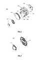
- FIG. 1Ais an exploded perspective view of an electric device according to an embodiment of the present invention including an enclosure.
- FIG. 1Bis an assembled, profile view of the electrical device depicted in FIG. 1A .
- FIG. 2is an exploded perspective view of a lighting apparatus according to an embodiment of the present invention.
- FIG. 3is a perspective view of a light emitting diode (LED) package of the lighting apparatus illustrated in FIG. 2 .
- LEDlight emitting diode
- FIG. 4is a perspective view of a heat sink of the lighting apparatus illustrated in FIG. 2 .
- FIG. 5is a perspective view of an enclosure of the lighting apparatus illustrated in FIG. 2 .
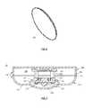
- FIG. 6is a perspective view of an optic of the lighting apparatus illustrated in FIG. 2 .
- FIG. 7is a cross sectional view of the electrical device illustrated in FIG. 1B taken through line 7 - 7 .
- an electrical device 10 operable to dissipate heat according to an embodiment of the present inventionis now described in greater detail.
- the electrical device 10may also be referred to as a device, lighting device, light fixture, or the invention. Alternate references of the electrical device 10 in this disclosure are not meant to be limiting in any way.
- the electronic lighting apparatus 100may include a light source 110 , a heat sink 120 , and a fluid flow generator 130 .
- the heat sink 120may be positioned adjacent the light source 110
- the fluid flow generator 1 . 30may be positioned in some proximity to the heat sink 120 .
- the fluid flow generator 130may be a device capable of creating a flow of fluid.
- the fluid flow generator 130may have a low profile, reducing the overall profile of the electronic lighting apparatus 100 .
- the fluid flow generator 130may be a micro-blower.
- the configuration of the micro-blowermay be made according to the disclosure of references incorporated herein. Additional details of low profile lights that may incorporate certain aspects of the present invention are found in U.S. Published Patent Application No. 2011/0080727 titled “Low Profile Light,” the entire contents of which is incorporated herein by reference.
- the fluid flow generator 130may operate at a variable rate. As a result, the fluid flow generated by the fluid flow generator 130 will vary accordingly, resulting in a variable fluid flow rate. To provide a sufficient, and not excessive, amount of heat dispersion capacity, the operation rate of the fluid flow generator 130 may be varied to generate a fluid flow rate suitable to maintain at least a portion of the electrical device 10 within a temperature range or at a thermal equilibrium, described in greater detail hereinbelow.
- the fluid flow generator 130may be carried by a support 140 .
- the support 140may be configured to carry the fluid flow generator 130 at some distance away from the heat sink 120 .
- the support 140may further be configured to carry the fluid flow generator 130 in a certain position and orientation such that the operation of the fluid flow generator 130 is controlled.
- the support 140may carry the fluid flow generator 130 such that the fluid flow generator 130 may create a fluid flow in the direction of the heat sink 120 .
- the support 140may include a pedestal 142 that is configured to attach to and support the fluid flow generator 130 .
- the pedestal 142may include an aperture 143 that facilitates the operation of the fluid flow generator 130 , permitting a fluid flow therethrough.
- the support 140may include one or more projecting members 145 projecting from the pedestal 142 into an area generally below the aperture 143 .
- the projecting members 145may be configured to carry and support the fluid flow generator 130 , permitting the fluid flow:generator 130 to interface with and rest atop the projecting members 145 .
- the support 140may further include a plurality of legs 144 attached to and extending generally away from the pedestal 142 .
- the plurality of legs 144 of the embodiment of the invention illustrated in the appended figuresincludes four legs. Those skilled in the art will readily appreciate that other embodiments may have any number of legs to provide sufficient structural support and stability to maintain the relative positions of the heat sink 120 and the fluid flow generator 130 .
- Each of the plurality of legs 144may include a tapered section 146 and a catch 148 that facilitates the attachment of the support 140 to a supporting element.
- the support 140may attach to the heat sink 120 .
- the support 140may be configured in any number of ways suitable for positioning the fluid flow generator a suitable distance and in a suitable orientation from the heat sink 120 to dissipate heat from the heat generating elements, i.e., the light source 110 , to the enclosure.
- the electrical device 10may be provided without use of a support 140 , wherein the fluid flow generator 130 instead interfaces directly with the heat sink 120 .
- the fluid flow generator 130may be attached to the heat sink 120 by any method capable of preventing movement of the fluid flow generator 130 with respect to the heat sink 120 .
- Such methodsinclude, without any intent to limit attachment methods to this list, adhesives, glues, fasteners, latches, and any other method known in the art.
- the light source 110may include any device capable of emitting light. These lights may, for example and without limitation, include incandescent lights, halogens, fluorescents (including compact-fluorescents), high-intensity discharges, light emitting diodes (LEDs), lasers, and any other light-emitting device known in the art.
- the light source 110is an LED package. Referring to FIG. 3 , where the light source 110 is an LED package, the LED package may include an LED 112 and a circuit board 114 . The circuit board 114 is configured to be functionally coupled to the LED 112 .
- the heat sink 120is positioned adjacent the light source 110 . Furthermore, the heat sink 120 may be thermally coupled to the light source 110 . This thermal coupling may be accomplished by any method, including thermal adhesives, thermal pastes, thermal greases, thermal pads, and all other methods known in the art. Where a thermal adhesive, paste, or grease is used, the heat sink 120 may be connected to any part of the light source 110 as may effectively cause thermal transfer between the light source 110 and the heat sink 120 . This will largely depend on the heat distribution within the light source 110 . For example, the heat sink 120 may be thermally coupled to the LED 112 , the circuit board 114 , or both. The method and location of thermal coupling may be selected based on criteria including ease of application/installation, thermal conductivity, chemical stability, structural stability, and constraints placed by the electrical device 10 .
- the heat sink 120may be a micro-channel heat sink including a number of fins 122 configured to provide a larger surface area than may otherwise be provided by the surface of the light source 110 .
- the configuration of the fins 122may be configured according to the direction of the incorporated references.
- the illustrated embodimentshows the plurality of fins 122 being curved to advantageously provide additional surface area to provide additional dissipation of heat.
- the fins 122 of the heat sink 120may be configured in any way while still accomplishing the many goals, features and advantages according to the present invention.
- the heat sink 120may include a base plate 124 from which the fins 122 project.
- the base plate 124may be configured to cooperate with the tapered sections 146 and catches 148 of the plurality of legs 144 (shown in FIG. 2 ), permitting the support 140 to attach thereto.
- the base plate 124may be configured into any shape, including a circle, ovoid, square, rectangle, triangle, or any other polygon.
- the heat sink 120may be made of a thermally conductive material. Materials include, without limitation, metals, metal alloys, carbon allotropes, ceramics, and composite materials. Accordingly, and as may be understood by those skilled in the art, the heat sink 120 advahtageously provides additional surface area for heat that may be produced to be dissipated.
- the electrical device 10includes an enclosure 200 .
- the enclosure 200may be configured to define an interior volume.
- the interior volumemay be isolated from the environment such that fluid from the environment is not able to gain entry to the interior volume and intermix with the fluid contained therein. Hence, a fluid seal is created about the interior volume of the enclosure 200 .
- Types of fluid contained by the enclosuremay be liquid or gaseous.
- the interior volume of the enclosure 200may be configured to have spatial characteristics permitting fluid flow within the interior volume.
- the fluid flow within the interior volumecauses the transfer of heat from the electrical device 10 to the enclosure 200 , which then transfers the heat to the environment.
- the heatis transferred from the electrical device 10 to the heat sink 120 and, in turn, due to the fluid flow created by the fluid flow generator 130 , to the interior volume of the enclosure 200 and, thereafter, to the environment.
- the spatial characteristics of the interior volumedirectly corresponds to the amount of heat that can be transported from the electrical device 10 to the environment. Spatial characteristics that can be modified include total volume, fluid flow characteristics, interior surface area, and exterior surface area.
- one or more surfaces of the enclosure 200may be textured or include grooves to increase the surface area of the surface, thereby facilitating thermal transfer thereto.
- the enclosure 200may include generally rounded interior surfaces reducing the aerodynamic profile of the enclosure 200 , thereby reducing drag experienced by fluid flowing therein.
- thermal properties of the materials used to form the enclosure 200may be considered in forming the enclosure 200 .
- a heat generating element with a relatively high amount of heat generationmay have a first enclosure configured to accommodate a high amount of heat dissipation, and a heat generating element with a relatively low amount of heat generation may have a second enclosure configured to accommodate a low amount of heat dissipation.
- the volume of the interior volumemay be directly proportional to the thermal output of the electrical device 10 .
- a surface area of some part of the enclosure 200may be proportional to the thermal output of the electrical device 10 .
- the interior volumemay be configured to maintain the temperature of the electrical device at thermal equilibrium or within a target temperature range. For instance, and without limitation, the thermal equilibrium may be 25 degrees Celsius, or the upper limit on the target temperature range may be 25 degrees Celsius.
- the enclosure 200may include a base member 202 .
- the base member 202includes a base 204 and a sidewall 206 , the sidewall 206 projecting from a surface of the base 204 .
- the base member 202may be formed into any shape, including a circle, ovoid, square, rectangle, triangle, or any other polygon.
- the sidewall 206may be configured to project generally orthogonally from the surface of the base 204 at the perimeter thereof, although the sidewall 206 may be configured to project from the base 204 at any angle.
- the sidewall 206further includes a projecting member 208 formed in a thickness of the sidewall 206 .
- the projecting member 208may be configured to facilitate the formation of a fluid seal, described in detail hereinbelow.
- the enclosure 200may include a wire portal 210 .
- the wire portal 210is configured to permit wiring connected to devices at least partially contained within the enclosure 200 to exit the enclosure 200 .
- the wire portal 210is disposed on the base member 202 .
- Other embodimentsmay have the wire portal 210 disposed on other parts of the enclosure 200 .
- the wire portal 210may include an aperture 212 of sufficient diameter to permit the aforementioned wires to pass therethrough.
- the wire portal 210may further include a sealing member.
- the sealing membermay include any device or material that can provide a fluid seal as described above.
- the sealing membermay include an adhesive disposed about wires passing through the aperture 212 , forming a fluid seal in the space between the wires and the aperture 212 .
- the enclosure 200may further include an attaching member 220 .
- The, attaching member 220may include a sidewall 222 and an optic receiving portion 224 .
- the sidewall 222may have a generally curved shape and may include a ledge 223 extending generally away from the sidewall 222 .
- the ledge 223may be configured to cooperate with the projecting member 208 to form a fluid seal therebetween.
- a fluid sealmay be formed between the ledge 223 and the projecting member 208 by any suitable method, including interference fit, use of adhesives, gasket, or any other method known in the art.
- methods of forming a fluid seal between the sidewall 206 of the base member 202 and the sidewall 222 of the attaching member 210 aside from those disclosed hereinaboveare contemplated by the invention.
- the optic receiving section 224may attach to the sidewall 222 .
- the optic receiving section 224is configured to define an aperture 226 .
- the aperture 226may be configured to be centered at a longitudinal axis of the attaching member 220 .
- the aperture 226may be defined by a series of walls included in the optic receiving section 224 .
- the first wall 230may be generally parallel to the base 204 of the base member 202 .
- the second wall 232may have a curved shape and may extend generally away from the first wall 230 .
- the third wall 234may extend from the second wall 232 and be generally parallel to the base 204 of the base member 202 .
- the third wall 234may attach to and form a seal with a part of the electronic lighting apparatus 100 .
- the first wall 230 , second wall 232 , and third wall 234taken with the sidewall 222 , may give the attaching member 220 a generally annular shape, with the aperture 226 forming the void of the
- an optic 300is provided according to an embodiment of the present invention.
- the optic 300may be configured to interact with light emitted by the light source 110 to refract incident light. Accordingly, the light source 110 may be disposed such that light emitted therefrom is incident upon the optic 300 .
- the optic 300may be formed in any shape to impart a desired refraction. In the present embodiment, the optic 300 has a generally concave geometry.
- the optic 300may further be formed so as to cooperate with the optic receiving section 224 , enabling the optic 300 to be carried by the optic receiving section 224 .
- the optic 300may be formed of any material with transparent or translucent properties that comport with the desired refraction to be performed by the optic 300 .
- the electrical device 10 as shown in FIGS. 1-6is in an assembled state, and the illustration represents a cross sectional view of the assembled electrical device.
- the projecting member 208 of the base member 202interfaces with the ledge 223 of the attaching member 220 to attach the base member 202 to the attaching member 220 , forming a fluid seal therebetween.
- the electronic lighting apparatus 100may be disposed at least partially within the interior volume defined by the enclosure 200 . In the present embodiment, at least portions of the heat sink 120 , fluid flow generator 130 , and support 140 are disposed within the interior volume.
- the third wall 234may attach to a portion of the electronic lighting apparatus 100 .
- the attachmentmay create a fluid seal, which, in conjunction with the fluid seal formed between the base member 202 and the attaching member 220 , forms a complete fluid seal and isolates the interior volume from the environment.
- the third wall 234may interface with at least one of the heat sink 120 and the support 140 , specifically the plurality of legs 144 .
- a sealing membermay be used. Types of sealing members included are adhesives, gaskets, interference fits, and any other method of forming a seal known in the art.
- the LED 112 and the circuit board 114are substantially outside the sealed interior volume.
- the optic 300is also substantially outside the sealed interior volume.
- the optic 300may interface with the optic receiving section 224 to attach to and be carried by the attachment member 220 .
- the optic 300may form an interference fit with the second wall 232 , the interference fit providing sufficient strength to carry the optic 300 thereby.
- the optic 300may be attached to the optic receiving section 224 through the use of an adhesive, glue, or any other attachment method known in the art.
- various aspects of the electrical device 10may be configured to direct the flow of fluid within the enclosure 200 from the fluid flow generator 130 to the heat sink 120 , then to a surface of the enclosure 120 .
- the fluid flow generator 120may be positioned so as to direct a flow of fluid at the heat sink 120 .
- the fluid flow generator 130is positioned above the heat sink 120 .
- the fluid flow generator 130may be positioned to cooperate with micro-channels that may be present in the heat sink 120 .
- the fluid flow generator 130may direct a flow fluid directly down into the micro-channels of the heat sink 120 , wherein the fluid flows through the micro channels and is directed laterally outward from the heat sink 120 .
- the continuous flow of fluid caused by the fluid flow generator 130may create a circulatory flow of fluid within the enclosure 200 , wherein fluid that has been heated by contact with the heat sink 120 is circulated to various spaces within the interior volume of the enclosure 200 .
- a method of operating an electrical device substantially as described aboveis also included within the scope of the invention.
- One method of useincludes the operation of the heat generating element.
- the heat generating elementis a light source.
- the operation of the heat generating elementcauses the creation of heat within the electrical device.
- the heat sinkis placed adjacent to the heat generating element, and may further be thermally coupled to the heat generating element to facilitate the transmission of heat from the heat generating to the heat sink.
- the method of usefurther includes the actuation of the fluid flow generator.
- the actuation of the fluid flow generatorcauses a fluid sealed within the enclosure to flow within the enclosure.
- the flow of fluidcomes into contact with the heat sink.
- the fluidmay contact any part of the heat sink, including, depending on the configuration of the heat sink, a base, a fin, or movement of fluid through a micro-channel of the heat sink.
- the contact between the heat sink and the fluidcauses the transfer of heat from the heat sink to the fluid.
- the flow of the fluidcauses the heated fluid to move out of contact with the heat sink and into another space within the interior volume of the enclosure. While the heated fluid is moving, it is continuously transferring heat to non-heated fluid contained within the enclosure that the heated fluid may come into contact with. Additionally, should heated fluid come into contact with a surface of the enclosure, the heated fluid may transfer heat to that surface.
Landscapes
- Engineering & Computer Science (AREA)
- General Engineering & Computer Science (AREA)
- Cooling Or The Like Of Electrical Apparatus (AREA)
- Arrangement Of Elements, Cooling, Sealing, Or The Like Of Lighting Devices (AREA)
- Cooling Or The Like Of Semiconductors Or Solid State Devices (AREA)
Abstract
Description
Claims (50)
Priority Applications (5)
| Application Number | Priority Date | Filing Date | Title |
|---|---|---|---|
| US13/461,333US8608348B2 (en) | 2011-05-13 | 2012-05-01 | Sealed electrical device with cooling system and associated methods |
| EP12725920.8AEP2707654A1 (en) | 2011-05-13 | 2012-05-14 | Sound baffling cooling system for led thermal management and associated methods |
| PCT/US2012/037760WO2012158607A1 (en) | 2011-05-13 | 2012-05-14 | Sound baffling cooling system for led thermal management and associated methods |
| US14/084,118US9151482B2 (en) | 2011-05-13 | 2013-11-19 | Sealed electrical device with cooling system |
| US14/591,521US9360202B2 (en) | 2011-05-13 | 2015-01-07 | System for actively cooling an LED filament and associated methods |
Applications Claiming Priority (2)
| Application Number | Priority Date | Filing Date | Title |
|---|---|---|---|
| US13/107,782US20120285667A1 (en) | 2011-05-13 | 2011-05-13 | Sound baffling cooling system for led thermal management and associated methods |
| US13/461,333US8608348B2 (en) | 2011-05-13 | 2012-05-01 | Sealed electrical device with cooling system and associated methods |
Related Parent Applications (2)
| Application Number | Title | Priority Date | Filing Date |
|---|---|---|---|
| US13/107,782Continuation-In-PartUS20120285667A1 (en) | 2011-05-13 | 2011-05-13 | Sound baffling cooling system for led thermal management and associated methods |
| US14/591,521Continuation-In-PartUS9360202B2 (en) | 2011-05-13 | 2015-01-07 | System for actively cooling an LED filament and associated methods |
Related Child Applications (2)
| Application Number | Title | Priority Date | Filing Date |
|---|---|---|---|
| US14/084,118ContinuationUS9151482B2 (en) | 2011-05-13 | 2013-11-19 | Sealed electrical device with cooling system |
| US14/084,118Continuation-In-PartUS9151482B2 (en) | 2011-05-13 | 2013-11-19 | Sealed electrical device with cooling system |
Publications (2)
| Publication Number | Publication Date |
|---|---|
| US20130021802A1 US20130021802A1 (en) | 2013-01-24 |
| US8608348B2true US8608348B2 (en) | 2013-12-17 |
Family
ID=46208773
Family Applications (1)
| Application Number | Title | Priority Date | Filing Date |
|---|---|---|---|
| US13/461,333Active - ReinstatedUS8608348B2 (en) | 2011-05-13 | 2012-05-01 | Sealed electrical device with cooling system and associated methods |
Country Status (3)
| Country | Link |
|---|---|
| US (1) | US8608348B2 (en) |
| EP (1) | EP2707654A1 (en) |
| WO (1) | WO2012158607A1 (en) |
Cited By (8)
| Publication number | Priority date | Publication date | Assignee | Title |
|---|---|---|---|---|
| US20140211486A1 (en)* | 2013-01-30 | 2014-07-31 | Edward T. Rodriguez | Heat exchanger for led light fixture |
| US9127818B2 (en) | 2012-10-03 | 2015-09-08 | Lighting Science Group Corporation | Elongated LED luminaire and associated methods |
| US9151482B2 (en) | 2011-05-13 | 2015-10-06 | Lighting Science Group Corporation | Sealed electrical device with cooling system |
| US9360202B2 (en) | 2011-05-13 | 2016-06-07 | Lighting Science Group Corporation | System for actively cooling an LED filament and associated methods |
| US9429294B2 (en) | 2013-11-11 | 2016-08-30 | Lighting Science Group Corporation | System for directional control of light and associated methods |
| US9459397B2 (en) | 2013-03-12 | 2016-10-04 | Lighting Science Group Corporation | Edge lit lighting device |
| US9581756B2 (en) | 2009-10-05 | 2017-02-28 | Lighting Science Group Corporation | Light guide for low profile luminaire |
| US10794667B2 (en) | 2017-01-04 | 2020-10-06 | Rolls-Royce Corporation | Optical thermal profile |
Families Citing this family (4)
| Publication number | Priority date | Publication date | Assignee | Title |
|---|---|---|---|---|
| US9157581B2 (en) | 2009-10-05 | 2015-10-13 | Lighting Science Group Corporation | Low profile luminaire with light guide and associated systems and methods |
| WO2015045554A1 (en)* | 2013-09-26 | 2015-04-02 | シャープ株式会社 | Bio-information-acquiring device and bio-information-acquiring method |
| WO2017075721A1 (en)* | 2015-11-03 | 2017-05-11 | Ade Photonexa Gmbh | Method for cooling an led lighting means arranged on a heat sink |
| CN205208491U (en)* | 2015-12-08 | 2016-05-04 | 东莞祥龙五金制品有限公司 | LED maize lamp heat dissipation module |
Citations (103)
| Publication number | Priority date | Publication date | Assignee | Title |
|---|---|---|---|---|
| US5057908A (en) | 1990-07-10 | 1991-10-15 | Iowa State University Research Foundation, Inc. | High power semiconductor device with integral heat sink |
| US5523878A (en) | 1994-06-30 | 1996-06-04 | Texas Instruments Incorporated | Self-assembled monolayer coating for micro-mechanical devices |
| US5704701A (en) | 1992-03-05 | 1998-01-06 | Rank Brimar Limited | Spatial light modulator system |
| US5997150A (en) | 1995-10-25 | 1999-12-07 | Texas Instruments Incorporated | Multiple emitter illuminator engine |
| US6140646A (en) | 1998-12-17 | 2000-10-31 | Sarnoff Corporation | Direct view infrared MEMS structure |
| US6341876B1 (en) | 1997-02-19 | 2002-01-29 | Digital Projection Limited | Illumination system |
| US6356700B1 (en) | 1998-06-08 | 2002-03-12 | Karlheinz Strobl | Efficient light engine systems, components and methods of manufacture |
| US6561656B1 (en) | 2001-09-17 | 2003-05-13 | Mitsubishi Denki Kabushiki Kaisha | Illumination optical system with reflecting light valve |
| US6594090B2 (en) | 2001-08-27 | 2003-07-15 | Eastman Kodak Company | Laser projection display system |
| US20040052076A1 (en) | 1997-08-26 | 2004-03-18 | Mueller George G. | Controlled lighting methods and apparatus |
| US6733135B2 (en) | 2002-04-02 | 2004-05-11 | Samsung Electronics Co., Ltd. | Image projection apparatus |
| US6767111B1 (en) | 2003-02-26 | 2004-07-27 | Kuo-Yen Lai | Projection light source from light emitting diodes |
| US6817735B2 (en) | 2001-05-24 | 2004-11-16 | Matsushita Electric Industrial Co., Ltd. | Illumination light source |
| US6870523B1 (en) | 2000-06-07 | 2005-03-22 | Genoa Color Technologies | Device, system and method for electronic true color display |
| US6871982B2 (en) | 2003-01-24 | 2005-03-29 | Digital Optics International Corporation | High-density illumination system |
| US6964501B2 (en)* | 2002-12-24 | 2005-11-15 | Altman Stage Lighting Co., Ltd. | Peltier-cooled LED lighting assembly |
| US6967761B2 (en) | 2000-10-31 | 2005-11-22 | Microsoft Corporation | Microelectrical mechanical structure (MEMS) optical modulator and optical display system |
| US6974713B2 (en) | 2000-08-11 | 2005-12-13 | Reflectivity, Inc. | Micromirrors with mechanisms for enhancing coupling of the micromirrors with electrostatic fields |
| US20060002108A1 (en) | 2004-06-30 | 2006-01-05 | Ouderkirk Andrew J | Phosphor based illumination system having a short pass reflector and method of making same |
| US20060002110A1 (en) | 2004-03-15 | 2006-01-05 | Color Kinetics Incorporated | Methods and systems for providing lighting systems |
| US7042623B1 (en) | 2004-10-19 | 2006-05-09 | Reflectivity, Inc | Light blocking layers in MEMS packages |
| US7070281B2 (en) | 2002-12-04 | 2006-07-04 | Nec Viewtechnology, Ltd. | Light source device and projection display |
| US7072096B2 (en) | 2001-12-14 | 2006-07-04 | Digital Optics International, Corporation | Uniform illumination system |
| US7075707B1 (en) | 1998-11-25 | 2006-07-11 | Research Foundation Of The University Of Central Florida, Incorporated | Substrate design for optimized performance of up-conversion phosphors utilizing proper thermal management |
| US20060164607A1 (en) | 2005-01-25 | 2006-07-27 | Morejon Israel J | Light-emitting diode (LED) illumination system for a digital micro-mirror device (DMD) and method of providing same |
| US20060164005A1 (en) | 2005-01-25 | 2006-07-27 | Chuan-Sheng Sun | Illumination apparatus having adjustable color temperature and method for adjusting the color temperature |
| US7083304B2 (en) | 2003-08-01 | 2006-08-01 | Illumination Management Solutions, Inc. | Apparatus and method of using light sources of differing wavelengths in an unitized beam |
| US20060285193A1 (en) | 2005-06-03 | 2006-12-21 | Fuji Photo Film Co., Ltd. | Optical modulation element array |
| US20070013871A1 (en) | 2005-07-15 | 2007-01-18 | Marshall Stephen W | Light-emitting diode (LED) illumination in display systems using spatial light modulators (SLM) |
| US7178941B2 (en) | 2003-05-05 | 2007-02-20 | Color Kinetics Incorporated | Lighting methods and systems |
| US7184201B2 (en) | 2004-11-02 | 2007-02-27 | Texas Instruments Incorporated | Digital micro-mirror device having improved contrast and method for the same |
| US7246923B2 (en) | 2004-02-11 | 2007-07-24 | 3M Innovative Properties Company | Reshaping light source modules and illumination systems using the same |
| US7255469B2 (en) | 2004-06-30 | 2007-08-14 | 3M Innovative Properties Company | Phosphor based illumination system having a light guide and an interference reflector |
| US20070188847A1 (en) | 2006-02-14 | 2007-08-16 | Texas Instruments Incorporated | MEMS device and method |
| US7261453B2 (en) | 2005-01-25 | 2007-08-28 | Morejon Israel J | LED polarizing optics for color illumination system and method of using same |
| US20070241340A1 (en) | 2006-04-17 | 2007-10-18 | Pan Shaoher X | Micro-mirror based display device having an improved light source |
| US7289090B2 (en) | 2003-12-10 | 2007-10-30 | Texas Instruments Incorporated | Pulsed LED scan-ring array for boosting display system lumens |
| US7300177B2 (en) | 2004-02-11 | 2007-11-27 | 3M Innovative Properties | Illumination system having a plurality of light source modules disposed in an array with a non-radially symmetrical aperture |
| US7303291B2 (en) | 2004-03-31 | 2007-12-04 | Sanyo Electric Co., Ltd. | Illumination apparatus and video projection display system |
| US7342658B2 (en) | 2005-12-28 | 2008-03-11 | Eastman Kodak Company | Programmable spectral imaging system |
| US20080062644A1 (en) | 2006-09-12 | 2008-03-13 | Gelcore, Llc | Piezofan and heat sink system for enhanced heat transfer |
| US7344279B2 (en) | 2003-12-11 | 2008-03-18 | Philips Solid-State Lighting Solutions, Inc. | Thermal management methods and apparatus for lighting devices |
| US7349095B2 (en) | 2005-05-19 | 2008-03-25 | Casio Computer Co., Ltd. | Light source apparatus and projection apparatus |
| US7353859B2 (en) | 2004-11-24 | 2008-04-08 | General Electric Company | Heat sink with microchannel cooling for power devices |
| US7382632B2 (en) | 2005-04-06 | 2008-06-03 | International Business Machines Corporation | Computer acoustic baffle and cable management system |
| US7382091B2 (en) | 2005-07-27 | 2008-06-03 | Lung-Chien Chen | White light emitting diode using phosphor excitation |
| US20080143973A1 (en) | 2006-10-12 | 2008-06-19 | Jing Miau Wu | Light source device of laser LED and projector having the same device |
| US20080198572A1 (en) | 2007-02-21 | 2008-08-21 | Medendorp Nicholas W | LED lighting systems including luminescent layers on remote reflectors |
| US7427146B2 (en) | 2004-02-11 | 2008-09-23 | 3M Innovative Properties Company | Light-collecting illumination system |
| US20080232084A1 (en) | 2007-03-19 | 2008-09-25 | Nec Lighting, Ltd | White light source device |
| US7429983B2 (en) | 2005-11-01 | 2008-09-30 | Cheetah Omni, Llc | Packet-based digital display system |
| US7434946B2 (en) | 2005-06-17 | 2008-10-14 | Texas Instruments Incorporated | Illumination system with integrated heat dissipation device for use in display systems employing spatial light modulators |
| US7438443B2 (en) | 2003-09-19 | 2008-10-21 | Ricoh Company, Limited | Lighting device, image-reading device, color-document reading apparatus, image-forming apparatus, projection apparatus |
| US7476016B2 (en) | 2005-06-28 | 2009-01-13 | Seiko Instruments Inc. | Illuminating device and display device including the same |
| US20090059099A1 (en) | 2007-09-05 | 2009-03-05 | Samsung Electronics Co., Ltd. | Illumination device and projection system having the same |
| US20090059585A1 (en) | 2007-08-29 | 2009-03-05 | Young Optics Inc. | Illumination system |
| US7530708B2 (en) | 2004-10-04 | 2009-05-12 | Lg Electronics Inc. | Surface emitting light source and projection display device using the same |
| US20090128781A1 (en) | 2006-06-13 | 2009-05-21 | Kenneth Li | LED multiplexer and recycler and micro-projector incorporating the Same |
| US7537347B2 (en) | 2005-11-29 | 2009-05-26 | Texas Instruments Incorporated | Method of combining dispersed light sources for projection display |
| US7540616B2 (en) | 2005-12-23 | 2009-06-02 | 3M Innovative Properties Company | Polarized, multicolor LED-based illumination source |
| US7556406B2 (en) | 2003-03-31 | 2009-07-07 | Lumination Llc | Led light with active cooling |
| US20090232683A1 (en) | 2006-12-09 | 2009-09-17 | Murata Manufacturing Co., Ltd. | Piezoelectric micro-blower |
| US7598686B2 (en) | 1997-12-17 | 2009-10-06 | Philips Solid-State Lighting Solutions, Inc. | Organic light emitting diode methods and apparatus |
| US7605971B2 (en) | 2003-11-01 | 2009-10-20 | Silicon Quest Kabushiki-Kaisha | Plurality of hidden hinges for mircromirror device |
| US20090262516A1 (en) | 2008-01-17 | 2009-10-22 | Intematix Corporation | Light emitting device with phosphor wavelength conversion |
| US7626755B2 (en) | 2007-01-31 | 2009-12-01 | Panasonic Corporation | Wavelength converter and two-dimensional image display device |
| US20100006762A1 (en) | 2007-03-27 | 2010-01-14 | Kabushiki Kaisha Toshiba | Scintillator panel and radiation detector |
| US20100061078A1 (en) | 2008-09-10 | 2010-03-11 | Samsung Electronics Co., Ltd. | Light emitting device and system providing white light with various color temperatures |
| US20100061068A1 (en) | 2006-06-16 | 2010-03-11 | Alexander Geissler | Method for fixing an electrical or an electronic component, particularly a printed-circuit board, in a housing and fixing element therefor |
| US7677736B2 (en) | 2004-02-27 | 2010-03-16 | Panasonic Corporation | Illumination light source and two-dimensional image display using same |
| US7684007B2 (en) | 2004-08-23 | 2010-03-23 | The Boeing Company | Adaptive and interactive scene illumination |
| US7703943B2 (en) | 2007-05-07 | 2010-04-27 | Intematix Corporation | Color tunable light source |
| US20100103389A1 (en) | 2008-10-28 | 2010-04-29 | Mcvea Kenneth Brian | Multi-MEMS Single Package MEMS Device |
| US7709811B2 (en) | 2007-07-03 | 2010-05-04 | Conner Arlie R | Light emitting diode illumination system |
| US7719766B2 (en) | 2007-06-20 | 2010-05-18 | Texas Instruments Incorporated | Illumination source and method therefor |
| US7766490B2 (en) | 2006-12-13 | 2010-08-03 | Philips Lumileds Lighting Company, Llc | Multi-color primary light generation in a projection system using LEDs |
| US20100202129A1 (en) | 2009-01-21 | 2010-08-12 | Abu-Ageel Nayef M | Illumination system utilizing wavelength conversion materials and light recycling |
| US20100231863A1 (en) | 2007-10-08 | 2010-09-16 | Koninklijke Philips Electronics N.V. | Lighting device, array of lighting devices and optical projection device |
| US20100244700A1 (en) | 2007-12-24 | 2010-09-30 | Patrick Chong | System for Representing Colors Including an Integrating Light Capsule |
| US7819556B2 (en) | 2006-12-22 | 2010-10-26 | Nuventix, Inc. | Thermal management system for LED array |
| US7828465B2 (en) | 2007-05-04 | 2010-11-09 | Koninlijke Philips Electronis N.V. | LED-based fixtures and related methods for thermal management |
| US7828453B2 (en) | 2009-03-10 | 2010-11-09 | Nepes Led Corporation | Light emitting device and lamp-cover structure containing luminescent material |
| US7832878B2 (en) | 2006-03-06 | 2010-11-16 | Innovations In Optics, Inc. | Light emitting diode projection system |
| US7835056B2 (en) | 2005-05-13 | 2010-11-16 | Her Majesty the Queen in Right of Canada, as represented by Institut National d'Optique | Image projector with flexible reflective analog modulator |
| US7834867B2 (en) | 2006-04-11 | 2010-11-16 | Microvision, Inc. | Integrated photonics module and devices using integrated photonics modules |
| US20100302464A1 (en) | 2009-05-29 | 2010-12-02 | Soraa, Inc. | Laser Based Display Method and System |
| US20100315320A1 (en) | 2007-12-07 | 2010-12-16 | Sony Corporation | Light source device and display device |
| US20100320928A1 (en) | 2008-02-13 | 2010-12-23 | Canon Components, Inc. | White light emitting apparatus and line illuminator using the same in image reading apparatus |
| US20100321641A1 (en) | 2008-02-08 | 2010-12-23 | Koninklijke Philips Electronics N.V. | Light module device |
| US20100321933A1 (en) | 2005-05-10 | 2010-12-23 | Iwasaki Electric Co., Ltd. | Projector device, laminate type light-emitting diode device, and reflection type light-emitting diode unit |
| US7883241B2 (en)* | 2008-05-06 | 2011-02-08 | Asustek Computer Inc. | Electronic device and heat dissipation unit thereof |
| US7889430B2 (en) | 2006-05-09 | 2011-02-15 | Ostendo Technologies, Inc. | LED-based high efficiency illumination systems for use in projection systems |
| US20110051453A1 (en) | 2009-08-25 | 2011-03-03 | Satoshi Nagasawa | Vehicle light |
| US7928565B2 (en) | 2004-06-15 | 2011-04-19 | International Business Machines Corporation | Semiconductor device with a high thermal dissipation efficiency |
| US7976205B2 (en) | 2005-08-31 | 2011-07-12 | Osram Opto Semiconductors Gmbh | Light-emitting module, particularly for use in an optical projection apparatus |
| US20110188241A1 (en)* | 2010-02-04 | 2011-08-04 | Steve Walczak | Lighting system with light-emitting diodes |
| US8016443B2 (en) | 2008-05-02 | 2011-09-13 | Light Prescriptions Innovators, Llc | Remote-phosphor LED downlight |
| US8047660B2 (en) | 2005-09-13 | 2011-11-01 | Texas Instruments Incorporated | Projection system and method including spatial light modulator and compact diffractive optics |
| US8061857B2 (en) | 2008-11-21 | 2011-11-22 | Hong Kong Applied Science And Technology Research Institute Co. Ltd. | LED light shaping device and illumination system |
| US8070324B2 (en) | 2008-07-30 | 2011-12-06 | Mp Design Inc. | Thermal control system for a light-emitting diode fixture |
| US8083364B2 (en) | 2008-12-29 | 2011-12-27 | Osram Sylvania Inc. | Remote phosphor LED illumination system |
| US8096668B2 (en) | 2008-01-16 | 2012-01-17 | Abu-Ageel Nayef M | Illumination systems utilizing wavelength conversion materials |
| US8419249B2 (en)* | 2009-04-15 | 2013-04-16 | Stanley Electric Co., Ltd. | Liquid-cooled LED lighting device |
Family Cites Families (2)
| Publication number | Priority date | Publication date | Assignee | Title |
|---|---|---|---|---|
| EP2203679B1 (en)* | 2007-09-27 | 2012-05-30 | Philips Intellectual Property & Standards GmbH | Lighting device and method of cooling a lighting device |
| US8201968B2 (en) | 2009-10-05 | 2012-06-19 | Lighting Science Group Corporation | Low profile light |
- 2012
- 2012-05-01USUS13/461,333patent/US8608348B2/enactiveActive - Reinstated
- 2012-05-14EPEP12725920.8Apatent/EP2707654A1/ennot_activeWithdrawn
- 2012-05-14WOPCT/US2012/037760patent/WO2012158607A1/enactiveApplication Filing
Patent Citations (108)
| Publication number | Priority date | Publication date | Assignee | Title |
|---|---|---|---|---|
| US5057908A (en) | 1990-07-10 | 1991-10-15 | Iowa State University Research Foundation, Inc. | High power semiconductor device with integral heat sink |
| US5704701A (en) | 1992-03-05 | 1998-01-06 | Rank Brimar Limited | Spatial light modulator system |
| US5523878A (en) | 1994-06-30 | 1996-06-04 | Texas Instruments Incorporated | Self-assembled monolayer coating for micro-mechanical devices |
| US5997150A (en) | 1995-10-25 | 1999-12-07 | Texas Instruments Incorporated | Multiple emitter illuminator engine |
| US6341876B1 (en) | 1997-02-19 | 2002-01-29 | Digital Projection Limited | Illumination system |
| US20040052076A1 (en) | 1997-08-26 | 2004-03-18 | Mueller George G. | Controlled lighting methods and apparatus |
| US7845823B2 (en) | 1997-08-26 | 2010-12-07 | Philips Solid-State Lighting Solutions, Inc. | Controlled lighting methods and apparatus |
| US7598686B2 (en) | 1997-12-17 | 2009-10-06 | Philips Solid-State Lighting Solutions, Inc. | Organic light emitting diode methods and apparatus |
| US6356700B1 (en) | 1998-06-08 | 2002-03-12 | Karlheinz Strobl | Efficient light engine systems, components and methods of manufacture |
| US7075707B1 (en) | 1998-11-25 | 2006-07-11 | Research Foundation Of The University Of Central Florida, Incorporated | Substrate design for optimized performance of up-conversion phosphors utilizing proper thermal management |
| US6140646A (en) | 1998-12-17 | 2000-10-31 | Sarnoff Corporation | Direct view infrared MEMS structure |
| US6870523B1 (en) | 2000-06-07 | 2005-03-22 | Genoa Color Technologies | Device, system and method for electronic true color display |
| US6974713B2 (en) | 2000-08-11 | 2005-12-13 | Reflectivity, Inc. | Micromirrors with mechanisms for enhancing coupling of the micromirrors with electrostatic fields |
| US6967761B2 (en) | 2000-10-31 | 2005-11-22 | Microsoft Corporation | Microelectrical mechanical structure (MEMS) optical modulator and optical display system |
| US6817735B2 (en) | 2001-05-24 | 2004-11-16 | Matsushita Electric Industrial Co., Ltd. | Illumination light source |
| US6594090B2 (en) | 2001-08-27 | 2003-07-15 | Eastman Kodak Company | Laser projection display system |
| US6561656B1 (en) | 2001-09-17 | 2003-05-13 | Mitsubishi Denki Kabushiki Kaisha | Illumination optical system with reflecting light valve |
| US7400439B2 (en) | 2001-12-14 | 2008-07-15 | Digital Optics International Corporation | Uniform illumination system |
| US7072096B2 (en) | 2001-12-14 | 2006-07-04 | Digital Optics International, Corporation | Uniform illumination system |
| US6733135B2 (en) | 2002-04-02 | 2004-05-11 | Samsung Electronics Co., Ltd. | Image projection apparatus |
| US7070281B2 (en) | 2002-12-04 | 2006-07-04 | Nec Viewtechnology, Ltd. | Light source device and projection display |
| US6964501B2 (en)* | 2002-12-24 | 2005-11-15 | Altman Stage Lighting Co., Ltd. | Peltier-cooled LED lighting assembly |
| US6871982B2 (en) | 2003-01-24 | 2005-03-29 | Digital Optics International Corporation | High-density illumination system |
| US7520642B2 (en) | 2003-01-24 | 2009-04-21 | Digital Optics International Corporation | High-density illumination system |
| US6767111B1 (en) | 2003-02-26 | 2004-07-27 | Kuo-Yen Lai | Projection light source from light emitting diodes |
| US7556406B2 (en) | 2003-03-31 | 2009-07-07 | Lumination Llc | Led light with active cooling |
| US7178941B2 (en) | 2003-05-05 | 2007-02-20 | Color Kinetics Incorporated | Lighting methods and systems |
| US7083304B2 (en) | 2003-08-01 | 2006-08-01 | Illumination Management Solutions, Inc. | Apparatus and method of using light sources of differing wavelengths in an unitized beam |
| US7438443B2 (en) | 2003-09-19 | 2008-10-21 | Ricoh Company, Limited | Lighting device, image-reading device, color-document reading apparatus, image-forming apparatus, projection apparatus |
| US7605971B2 (en) | 2003-11-01 | 2009-10-20 | Silicon Quest Kabushiki-Kaisha | Plurality of hidden hinges for mircromirror device |
| US7289090B2 (en) | 2003-12-10 | 2007-10-30 | Texas Instruments Incorporated | Pulsed LED scan-ring array for boosting display system lumens |
| US7344279B2 (en) | 2003-12-11 | 2008-03-18 | Philips Solid-State Lighting Solutions, Inc. | Thermal management methods and apparatus for lighting devices |
| US7246923B2 (en) | 2004-02-11 | 2007-07-24 | 3M Innovative Properties Company | Reshaping light source modules and illumination systems using the same |
| US7427146B2 (en) | 2004-02-11 | 2008-09-23 | 3M Innovative Properties Company | Light-collecting illumination system |
| US7300177B2 (en) | 2004-02-11 | 2007-11-27 | 3M Innovative Properties | Illumination system having a plurality of light source modules disposed in an array with a non-radially symmetrical aperture |
| US7677736B2 (en) | 2004-02-27 | 2010-03-16 | Panasonic Corporation | Illumination light source and two-dimensional image display using same |
| US20060002110A1 (en) | 2004-03-15 | 2006-01-05 | Color Kinetics Incorporated | Methods and systems for providing lighting systems |
| US7303291B2 (en) | 2004-03-31 | 2007-12-04 | Sanyo Electric Co., Ltd. | Illumination apparatus and video projection display system |
| US7928565B2 (en) | 2004-06-15 | 2011-04-19 | International Business Machines Corporation | Semiconductor device with a high thermal dissipation efficiency |
| US20060002108A1 (en) | 2004-06-30 | 2006-01-05 | Ouderkirk Andrew J | Phosphor based illumination system having a short pass reflector and method of making same |
| US7255469B2 (en) | 2004-06-30 | 2007-08-14 | 3M Innovative Properties Company | Phosphor based illumination system having a light guide and an interference reflector |
| US7684007B2 (en) | 2004-08-23 | 2010-03-23 | The Boeing Company | Adaptive and interactive scene illumination |
| US7530708B2 (en) | 2004-10-04 | 2009-05-12 | Lg Electronics Inc. | Surface emitting light source and projection display device using the same |
| US7042623B1 (en) | 2004-10-19 | 2006-05-09 | Reflectivity, Inc | Light blocking layers in MEMS packages |
| US7184201B2 (en) | 2004-11-02 | 2007-02-27 | Texas Instruments Incorporated | Digital micro-mirror device having improved contrast and method for the same |
| US7353859B2 (en) | 2004-11-24 | 2008-04-08 | General Electric Company | Heat sink with microchannel cooling for power devices |
| US7325956B2 (en) | 2005-01-25 | 2008-02-05 | Jabil Circuit, Inc. | Light-emitting diode (LED) illumination system for a digital micro-mirror device (DMD) and method of providing same |
| US20060164607A1 (en) | 2005-01-25 | 2006-07-27 | Morejon Israel J | Light-emitting diode (LED) illumination system for a digital micro-mirror device (DMD) and method of providing same |
| US20060164005A1 (en) | 2005-01-25 | 2006-07-27 | Chuan-Sheng Sun | Illumination apparatus having adjustable color temperature and method for adjusting the color temperature |
| US7261453B2 (en) | 2005-01-25 | 2007-08-28 | Morejon Israel J | LED polarizing optics for color illumination system and method of using same |
| US7382632B2 (en) | 2005-04-06 | 2008-06-03 | International Business Machines Corporation | Computer acoustic baffle and cable management system |
| US8070302B2 (en) | 2005-05-10 | 2011-12-06 | Iwasaki Electric Co., Ltd. | Laminate type light-emitting diode device, and reflection type light-emitting diode unit |
| US20100321933A1 (en) | 2005-05-10 | 2010-12-23 | Iwasaki Electric Co., Ltd. | Projector device, laminate type light-emitting diode device, and reflection type light-emitting diode unit |
| US7835056B2 (en) | 2005-05-13 | 2010-11-16 | Her Majesty the Queen in Right of Canada, as represented by Institut National d'Optique | Image projector with flexible reflective analog modulator |
| US7349095B2 (en) | 2005-05-19 | 2008-03-25 | Casio Computer Co., Ltd. | Light source apparatus and projection apparatus |
| US20060285193A1 (en) | 2005-06-03 | 2006-12-21 | Fuji Photo Film Co., Ltd. | Optical modulation element array |
| US7434946B2 (en) | 2005-06-17 | 2008-10-14 | Texas Instruments Incorporated | Illumination system with integrated heat dissipation device for use in display systems employing spatial light modulators |
| US7476016B2 (en) | 2005-06-28 | 2009-01-13 | Seiko Instruments Inc. | Illuminating device and display device including the same |
| US20070013871A1 (en) | 2005-07-15 | 2007-01-18 | Marshall Stephen W | Light-emitting diode (LED) illumination in display systems using spatial light modulators (SLM) |
| US7382091B2 (en) | 2005-07-27 | 2008-06-03 | Lung-Chien Chen | White light emitting diode using phosphor excitation |
| US7976205B2 (en) | 2005-08-31 | 2011-07-12 | Osram Opto Semiconductors Gmbh | Light-emitting module, particularly for use in an optical projection apparatus |
| US8047660B2 (en) | 2005-09-13 | 2011-11-01 | Texas Instruments Incorporated | Projection system and method including spatial light modulator and compact diffractive optics |
| US7429983B2 (en) | 2005-11-01 | 2008-09-30 | Cheetah Omni, Llc | Packet-based digital display system |
| US7537347B2 (en) | 2005-11-29 | 2009-05-26 | Texas Instruments Incorporated | Method of combining dispersed light sources for projection display |
| US7540616B2 (en) | 2005-12-23 | 2009-06-02 | 3M Innovative Properties Company | Polarized, multicolor LED-based illumination source |
| US7342658B2 (en) | 2005-12-28 | 2008-03-11 | Eastman Kodak Company | Programmable spectral imaging system |
| US20070188847A1 (en) | 2006-02-14 | 2007-08-16 | Texas Instruments Incorporated | MEMS device and method |
| US7832878B2 (en) | 2006-03-06 | 2010-11-16 | Innovations In Optics, Inc. | Light emitting diode projection system |
| US7834867B2 (en) | 2006-04-11 | 2010-11-16 | Microvision, Inc. | Integrated photonics module and devices using integrated photonics modules |
| US20070241340A1 (en) | 2006-04-17 | 2007-10-18 | Pan Shaoher X | Micro-mirror based display device having an improved light source |
| US7889430B2 (en) | 2006-05-09 | 2011-02-15 | Ostendo Technologies, Inc. | LED-based high efficiency illumination systems for use in projection systems |
| US20090128781A1 (en) | 2006-06-13 | 2009-05-21 | Kenneth Li | LED multiplexer and recycler and micro-projector incorporating the Same |
| US20100061068A1 (en) | 2006-06-16 | 2010-03-11 | Alexander Geissler | Method for fixing an electrical or an electronic component, particularly a printed-circuit board, in a housing and fixing element therefor |
| US20080062644A1 (en) | 2006-09-12 | 2008-03-13 | Gelcore, Llc | Piezofan and heat sink system for enhanced heat transfer |
| US20080143973A1 (en) | 2006-10-12 | 2008-06-19 | Jing Miau Wu | Light source device of laser LED and projector having the same device |
| US20090232683A1 (en) | 2006-12-09 | 2009-09-17 | Murata Manufacturing Co., Ltd. | Piezoelectric micro-blower |
| US7766490B2 (en) | 2006-12-13 | 2010-08-03 | Philips Lumileds Lighting Company, Llc | Multi-color primary light generation in a projection system using LEDs |
| US7819556B2 (en) | 2006-12-22 | 2010-10-26 | Nuventix, Inc. | Thermal management system for LED array |
| US7626755B2 (en) | 2007-01-31 | 2009-12-01 | Panasonic Corporation | Wavelength converter and two-dimensional image display device |
| US20080198572A1 (en) | 2007-02-21 | 2008-08-21 | Medendorp Nicholas W | LED lighting systems including luminescent layers on remote reflectors |
| US20080232084A1 (en) | 2007-03-19 | 2008-09-25 | Nec Lighting, Ltd | White light source device |
| US20100006762A1 (en) | 2007-03-27 | 2010-01-14 | Kabushiki Kaisha Toshiba | Scintillator panel and radiation detector |
| US7828465B2 (en) | 2007-05-04 | 2010-11-09 | Koninlijke Philips Electronis N.V. | LED-based fixtures and related methods for thermal management |
| US7703943B2 (en) | 2007-05-07 | 2010-04-27 | Intematix Corporation | Color tunable light source |
| US7719766B2 (en) | 2007-06-20 | 2010-05-18 | Texas Instruments Incorporated | Illumination source and method therefor |
| US7709811B2 (en) | 2007-07-03 | 2010-05-04 | Conner Arlie R | Light emitting diode illumination system |
| US20090059585A1 (en) | 2007-08-29 | 2009-03-05 | Young Optics Inc. | Illumination system |
| US20090059099A1 (en) | 2007-09-05 | 2009-03-05 | Samsung Electronics Co., Ltd. | Illumination device and projection system having the same |
| US20100231863A1 (en) | 2007-10-08 | 2010-09-16 | Koninklijke Philips Electronics N.V. | Lighting device, array of lighting devices and optical projection device |
| US20100315320A1 (en) | 2007-12-07 | 2010-12-16 | Sony Corporation | Light source device and display device |
| US20100244700A1 (en) | 2007-12-24 | 2010-09-30 | Patrick Chong | System for Representing Colors Including an Integrating Light Capsule |
| US8096668B2 (en) | 2008-01-16 | 2012-01-17 | Abu-Ageel Nayef M | Illumination systems utilizing wavelength conversion materials |
| US20090262516A1 (en) | 2008-01-17 | 2009-10-22 | Intematix Corporation | Light emitting device with phosphor wavelength conversion |
| US20100321641A1 (en) | 2008-02-08 | 2010-12-23 | Koninklijke Philips Electronics N.V. | Light module device |
| US20100320928A1 (en) | 2008-02-13 | 2010-12-23 | Canon Components, Inc. | White light emitting apparatus and line illuminator using the same in image reading apparatus |
| US8016443B2 (en) | 2008-05-02 | 2011-09-13 | Light Prescriptions Innovators, Llc | Remote-phosphor LED downlight |
| US7883241B2 (en)* | 2008-05-06 | 2011-02-08 | Asustek Computer Inc. | Electronic device and heat dissipation unit thereof |
| US8070324B2 (en) | 2008-07-30 | 2011-12-06 | Mp Design Inc. | Thermal control system for a light-emitting diode fixture |
| US20100061078A1 (en) | 2008-09-10 | 2010-03-11 | Samsung Electronics Co., Ltd. | Light emitting device and system providing white light with various color temperatures |
| US20100103389A1 (en) | 2008-10-28 | 2010-04-29 | Mcvea Kenneth Brian | Multi-MEMS Single Package MEMS Device |
| US8061857B2 (en) | 2008-11-21 | 2011-11-22 | Hong Kong Applied Science And Technology Research Institute Co. Ltd. | LED light shaping device and illumination system |
| US8083364B2 (en) | 2008-12-29 | 2011-12-27 | Osram Sylvania Inc. | Remote phosphor LED illumination system |
| US20100202129A1 (en) | 2009-01-21 | 2010-08-12 | Abu-Ageel Nayef M | Illumination system utilizing wavelength conversion materials and light recycling |
| US7828453B2 (en) | 2009-03-10 | 2010-11-09 | Nepes Led Corporation | Light emitting device and lamp-cover structure containing luminescent material |
| US8419249B2 (en)* | 2009-04-15 | 2013-04-16 | Stanley Electric Co., Ltd. | Liquid-cooled LED lighting device |
| US20100302464A1 (en) | 2009-05-29 | 2010-12-02 | Soraa, Inc. | Laser Based Display Method and System |
| US20110051453A1 (en) | 2009-08-25 | 2011-03-03 | Satoshi Nagasawa | Vehicle light |
| US20110188241A1 (en)* | 2010-02-04 | 2011-08-04 | Steve Walczak | Lighting system with light-emitting diodes |
Non-Patent Citations (6)
| Title |
|---|
| Arthur P. Fraas, Heat Exchanger Design, 1989, p. 60, John Wiley & Sons, Inc., Canada. |
| H. A El-Shaikh, S. V. Garimella, "Enhancement of Air Jet Impingement Heat Transfer using Pin-Fin Heat Sinks", D IEEE Transactions on Components and Packaging Technology, Jun. 2000, vol. 23, No. 2. |
| J. Y. San, C. H. Huang, M. H, Shu, "Impingement cooling of a confined circular air jet", In t. J. Heat Mass Transf. , 1997. pp. 1355-1364, vol. 40. |
| N. T. Obot, W. J. Douglas, A S. Mujumdar, "Effect of Semi-confinement on Impingement Heat Transfer", Proc. 7th Int. Heat Transf. Conf., 1982, pp. 1355-1364. vol. 3. |
| S. A Solovitz, L. D. Stevanovic, R. A Beaupre, "Microchannels Take Heatsinks to the Next Level", Power Electronics Technology, Nov. 2006. |
| Yongmann M. Chung, Kai H. Luo, "Unsteady Heat Transfer Analysis of an Impinging Jet", Journal of Heat Transfer-Transactions of the ASME, Dec. 2002, pp. 1039-1048, vol. 124, No. 6. |
Cited By (9)
| Publication number | Priority date | Publication date | Assignee | Title |
|---|---|---|---|---|
| US9581756B2 (en) | 2009-10-05 | 2017-02-28 | Lighting Science Group Corporation | Light guide for low profile luminaire |
| US9151482B2 (en) | 2011-05-13 | 2015-10-06 | Lighting Science Group Corporation | Sealed electrical device with cooling system |
| US9360202B2 (en) | 2011-05-13 | 2016-06-07 | Lighting Science Group Corporation | System for actively cooling an LED filament and associated methods |
| US9127818B2 (en) | 2012-10-03 | 2015-09-08 | Lighting Science Group Corporation | Elongated LED luminaire and associated methods |
| US9353916B2 (en) | 2012-10-03 | 2016-05-31 | Lighting Science Group Corporation | Elongated LED luminaire and associated methods |
| US20140211486A1 (en)* | 2013-01-30 | 2014-07-31 | Edward T. Rodriguez | Heat exchanger for led light fixture |
| US9459397B2 (en) | 2013-03-12 | 2016-10-04 | Lighting Science Group Corporation | Edge lit lighting device |
| US9429294B2 (en) | 2013-11-11 | 2016-08-30 | Lighting Science Group Corporation | System for directional control of light and associated methods |
| US10794667B2 (en) | 2017-01-04 | 2020-10-06 | Rolls-Royce Corporation | Optical thermal profile |
Also Published As
| Publication number | Publication date |
|---|---|
| EP2707654A1 (en) | 2014-03-19 |
| WO2012158607A1 (en) | 2012-11-22 |
| US20130021802A1 (en) | 2013-01-24 |
Similar Documents
| Publication | Publication Date | Title |
|---|---|---|
| US8608348B2 (en) | Sealed electrical device with cooling system and associated methods | |
| JP4677016B2 (en) | Lighting device and heat dissipation mechanism thereof | |
| US9500355B2 (en) | Lamp with light emitting elements surrounding active cooling device | |
| EP1873448B1 (en) | A high power led illuminating equipment having high thermal diffusivity | |
| CN101310382B (en) | Heat exchange enhancement | |
| US8334640B2 (en) | Turbulent flow cooling for electronic ballast | |
| US9068701B2 (en) | Lamp structure with remote LED light source | |
| US20080180969A1 (en) | Heat Exchange Enhancement | |
| US9016899B2 (en) | Luminaire with modular cooling system and associated methods | |
| US20080285298A1 (en) | Heat Exchange Enhancement | |
| CN102650382B (en) | Lighting apparatus | |
| US20100264799A1 (en) | Led lamp | |
| US9163819B2 (en) | Light assembly with a heat dissipation layer | |
| JP2009245916A (en) | Lighting system, and heat-dissipating structure thereof | |
| JP3194796U (en) | Omni-directional LED bulb | |
| US9360202B2 (en) | System for actively cooling an LED filament and associated methods | |
| JP2010108768A (en) | Light source unit and lighting device | |
| KR101227526B1 (en) | Lighting apparatus | |
| US9151482B2 (en) | Sealed electrical device with cooling system | |
| JP3181991U (en) | Light emitting diode lamp | |
| KR101729743B1 (en) | LED lighting apparatus using LED radiant heat structure | |
| EP3746700B1 (en) | Squeezed profile to support lighting | |
| JP6019497B2 (en) | LED lighting device | |
| JP2016066694A (en) | Heat sink and lighting device | |
| JP6480117B2 (en) | LED lighting device |
Legal Events
| Date | Code | Title | Description |
|---|---|---|---|
| AS | Assignment | Owner name:LIGHTING SCIENCE GROUP CORPORATION, FLORIDA Free format text:ASSIGNMENT OF ASSIGNORS INTEREST;ASSIGNORS:MAXIK, FREDRIC S.;BARTINE, DAVID E.;SOLER, ROBERT R.;AND OTHERS;SIGNING DATES FROM 20120611 TO 20120612;REEL/FRAME:028475/0689 | |
| AS | Assignment | Owner name:LIGHTING SCIENCE GROUP CORPORATION, FLORIDA Free format text:ASSIGNMENT OF ASSIGNORS INTEREST;ASSIGNOR:OOSTDYK, MARK ANDREW;REEL/FRAME:029308/0941 Effective date:20121112 | |
| STCF | Information on status: patent grant | Free format text:PATENTED CASE | |
| AS | Assignment | Owner name:FCC, LLC D/B/A FIRST CAPITAL, AS AGENT, GEORGIA Free format text:SECURITY INTEREST;ASSIGNORS:LIGHTING SCIENCE GROUP CORPORATION;BIOLOGICAL ILLUMINATION, LLC;REEL/FRAME:032765/0910 Effective date:20140425 | |
| AS | Assignment | Owner name:MEDLEY CAPTIAL CORPORATION, AS AGENT, NEW YORK Free format text:SECURITY INTEREST;ASSIGNORS:LIGHTING SCIENCE GROUP CORPORATION;BIOLOGICAL ILLUMINATION, LLC;REEL/FRAME:033072/0395 Effective date:20140219 | |
| AS | Assignment | Owner name:ACF FINCO I LP, NEW YORK Free format text:ASSIGNMENT AND ASSUMPTION OF SECURITY INTERESTS IN PATENTS;ASSIGNOR:FCC, LLC D/B/A FIRST CAPITAL;REEL/FRAME:035774/0632 Effective date:20150518 | |
| AS | Assignment | Owner name:BIOLOGICAL ILLUMINATION, LLC, A DELAWARE LIMITED L Free format text:RELEASE BY SECURED PARTY;ASSIGNOR:ACF FINCO I LP, A DELAWARE LIMITED PARTNERSHIP;REEL/FRAME:042340/0471 Effective date:20170425 Owner name:LIGHTING SCIENCE GROUP CORPORATION, A DELAWARE COR Free format text:RELEASE BY SECURED PARTY;ASSIGNOR:ACF FINCO I LP, A DELAWARE LIMITED PARTNERSHIP;REEL/FRAME:042340/0471 Effective date:20170425 | |
| REMI | Maintenance fee reminder mailed | ||
| FEPP | Fee payment procedure | Free format text:SURCHARGE FOR LATE PAYMENT, SMALL ENTITY (ORIGINAL EVENT CODE: M2554) | |
| MAFP | Maintenance fee payment | Free format text:PAYMENT OF MAINTENANCE FEE, 4TH YR, SMALL ENTITY (ORIGINAL EVENT CODE: M2551) Year of fee payment:4 | |
| AS | Assignment | Owner name:BIOLOGICAL ILLUMINATION, LLC, A DELAWARE LIMITED L Free format text:RELEASE BY SECURED PARTY;ASSIGNOR:MEDLEY CAPITAL CORPORATION;REEL/FRAME:048018/0515 Effective date:20180809 Owner name:LIGHTING SCIENCE GROUP CORPORATION, A DELAWARE COR Free format text:RELEASE BY SECURED PARTY;ASSIGNOR:MEDLEY CAPITAL CORPORATION;REEL/FRAME:048018/0515 Effective date:20180809 | |
| FEPP | Fee payment procedure | Free format text:MAINTENANCE FEE REMINDER MAILED (ORIGINAL EVENT CODE: REM.); ENTITY STATUS OF PATENT OWNER: SMALL ENTITY | |
| LAPS | Lapse for failure to pay maintenance fees | Free format text:PATENT EXPIRED FOR FAILURE TO PAY MAINTENANCE FEES (ORIGINAL EVENT CODE: EXP.); ENTITY STATUS OF PATENT OWNER: SMALL ENTITY | |
| STCH | Information on status: patent discontinuation | Free format text:PATENT EXPIRED DUE TO NONPAYMENT OF MAINTENANCE FEES UNDER 37 CFR 1.362 | |
| FP | Lapsed due to failure to pay maintenance fee | Effective date:20211217 | |
| PRDP | Patent reinstated due to the acceptance of a late maintenance fee | Effective date:20221209 | |
| FEPP | Fee payment procedure | Free format text:PETITION RELATED TO MAINTENANCE FEES FILED (ORIGINAL EVENT CODE: PMFP); ENTITY STATUS OF PATENT OWNER: SMALL ENTITY Free format text:PETITION RELATED TO MAINTENANCE FEES GRANTED (ORIGINAL EVENT CODE: PMFG); ENTITY STATUS OF PATENT OWNER: SMALL ENTITY Free format text:SURCHARGE, PETITION TO ACCEPT PYMT AFTER EXP, UNINTENTIONAL. (ORIGINAL EVENT CODE: M2558); ENTITY STATUS OF PATENT OWNER: SMALL ENTITY | |
| MAFP | Maintenance fee payment | Free format text:PAYMENT OF MAINTENANCE FEE, 8TH YR, SMALL ENTITY (ORIGINAL EVENT CODE: M2552); ENTITY STATUS OF PATENT OWNER: SMALL ENTITY Year of fee payment:8 | |
| STCF | Information on status: patent grant | Free format text:PATENTED CASE | |
| FEPP | Fee payment procedure | Free format text:MAINTENANCE FEE REMINDER MAILED (ORIGINAL EVENT CODE: REM.); ENTITY STATUS OF PATENT OWNER: SMALL ENTITY |