US8606343B2 - System and method for confocal imaging within dermal tissue - Google Patents
System and method for confocal imaging within dermal tissueDownload PDFInfo
- Publication number
- US8606343B2 US8606343B2US11/784,128US78412807AUS8606343B2US 8606343 B2US8606343 B2US 8606343B2US 78412807 AUS78412807 AUS 78412807AUS 8606343 B2US8606343 B2US 8606343B2
- Authority
- US
- United States
- Prior art keywords
- tissue
- microscope
- patient
- recording medium
- imaged
- Prior art date
- Legal status (The legal status is an assumption and is not a legal conclusion. Google has not performed a legal analysis and makes no representation as to the accuracy of the status listed.)
- Expired - Fee Related, expires
Links
- 238000000034methodMethods0.000titleclaims5
- 238000010226confocal imagingMethods0.000titleabstractdescription40
- 230000002500effect on skinEffects0.000titleabstractdescription8
- 238000003384imaging methodMethods0.000claimsabstractdescription40
- 238000001727in vivoMethods0.000claimsdescription12
- 239000003550markerSubstances0.000claimsdescription5
- 230000003902lesionEffects0.000claimsdescription4
- 239000000463materialSubstances0.000claimsdescription4
- 230000000087stabilizing effectEffects0.000claimsdescription3
- 238000001000micrographMethods0.000claims4
- 238000013507mappingMethods0.000claims1
- 210000001519tissueAnatomy0.000description86
- 210000003128headAnatomy0.000description48
- 238000003475laminationMethods0.000description39
- 238000013016dampingMethods0.000description8
- 230000006835compressionEffects0.000description4
- 238000007906compressionMethods0.000description4
- XUMBMVFBXHLACL-UHFFFAOYSA-NMelaninChemical compoundO=C1C(=O)C(C2=CNC3=C(C(C(=O)C4=C32)=O)C)=C2C4=CNC2=C1CXUMBMVFBXHLACL-UHFFFAOYSA-N0.000description2
- 230000008901benefitEffects0.000description2
- 210000003679cervix uteriAnatomy0.000description2
- 239000006260foamSubstances0.000description2
- 239000007788liquidSubstances0.000description2
- 238000012634optical imagingMethods0.000description2
- 230000006641stabilisationEffects0.000description2
- 238000011105stabilizationMethods0.000description2
- 208000012661DyskinesiaDiseases0.000description1
- 229920001875EbonitePolymers0.000description1
- 239000006096absorbing agentSubstances0.000description1
- 230000002457bidirectional effectEffects0.000description1
- 239000002131composite materialSubstances0.000description1
- 210000001061foreheadAnatomy0.000description1
- 230000005484gravityEffects0.000description1
- 238000000386microscopyMethods0.000description1
- 238000012986modificationMethods0.000description1
- 230000004048modificationEffects0.000description1
- 230000003287optical effectEffects0.000description1
- 230000001575pathological effectEffects0.000description1
- 230000007170pathologyEffects0.000description1
- 230000000452restraining effectEffects0.000description1
- 230000035939shockEffects0.000description1
- 206010040882skin lesionDiseases0.000description1
- 231100000444skin lesionToxicity0.000description1
- 210000004894snoutAnatomy0.000description1
- 125000006850spacer groupChemical group0.000description1
Images


Classifications
- A—HUMAN NECESSITIES
- A61—MEDICAL OR VETERINARY SCIENCE; HYGIENE
- A61B—DIAGNOSIS; SURGERY; IDENTIFICATION
- A61B5/00—Measuring for diagnostic purposes; Identification of persons
- A61B5/68—Arrangements of detecting, measuring or recording means, e.g. sensors, in relation to patient
- A61B5/6801—Arrangements of detecting, measuring or recording means, e.g. sensors, in relation to patient specially adapted to be attached to or worn on the body surface
- A61B5/684—Indicating the position of the sensor on the body
- A61B5/6842—Indicating the position of the sensor on the body by marking the skin
- A—HUMAN NECESSITIES
- A61—MEDICAL OR VETERINARY SCIENCE; HYGIENE
- A61B—DIAGNOSIS; SURGERY; IDENTIFICATION
- A61B5/00—Measuring for diagnostic purposes; Identification of persons
- A61B5/0059—Measuring for diagnostic purposes; Identification of persons using light, e.g. diagnosis by transillumination, diascopy, fluorescence
- A61B5/0062—Arrangements for scanning
- A61B5/0068—Confocal scanning
- A—HUMAN NECESSITIES
- A61—MEDICAL OR VETERINARY SCIENCE; HYGIENE
- A61B—DIAGNOSIS; SURGERY; IDENTIFICATION
- A61B5/00—Measuring for diagnostic purposes; Identification of persons
- A61B5/06—Devices, other than using radiation, for detecting or locating foreign bodies ; Determining position of diagnostic devices within or on the body of the patient
- A61B5/061—Determining position of a probe within the body employing means separate from the probe, e.g. sensing internal probe position employing impedance electrodes on the surface of the body
- A—HUMAN NECESSITIES
- A61—MEDICAL OR VETERINARY SCIENCE; HYGIENE
- A61B—DIAGNOSIS; SURGERY; IDENTIFICATION
- A61B5/00—Measuring for diagnostic purposes; Identification of persons
- A61B5/44—Detecting, measuring or recording for evaluating the integumentary system, e.g. skin, hair or nails
- A61B5/441—Skin evaluation, e.g. for skin disorder diagnosis
- A61B5/444—Evaluating skin marks, e.g. mole, nevi, tumour, scar
- A—HUMAN NECESSITIES
- A61—MEDICAL OR VETERINARY SCIENCE; HYGIENE
- A61B—DIAGNOSIS; SURGERY; IDENTIFICATION
- A61B5/00—Measuring for diagnostic purposes; Identification of persons
- A61B5/44—Detecting, measuring or recording for evaluating the integumentary system, e.g. skin, hair or nails
- A61B5/441—Skin evaluation, e.g. for skin disorder diagnosis
- A61B5/445—Evaluating skin irritation or skin trauma, e.g. rash, eczema, wound, bed sore
- A—HUMAN NECESSITIES
- A61—MEDICAL OR VETERINARY SCIENCE; HYGIENE
- A61B—DIAGNOSIS; SURGERY; IDENTIFICATION
- A61B5/00—Measuring for diagnostic purposes; Identification of persons
- A61B5/68—Arrangements of detecting, measuring or recording means, e.g. sensors, in relation to patient
- A61B5/6801—Arrangements of detecting, measuring or recording means, e.g. sensors, in relation to patient specially adapted to be attached to or worn on the body surface
- A61B5/683—Means for maintaining contact with the body
- A61B5/6834—Means for maintaining contact with the body using vacuum
- A—HUMAN NECESSITIES
- A61—MEDICAL OR VETERINARY SCIENCE; HYGIENE
- A61B—DIAGNOSIS; SURGERY; IDENTIFICATION
- A61B5/00—Measuring for diagnostic purposes; Identification of persons
- A61B5/68—Arrangements of detecting, measuring or recording means, e.g. sensors, in relation to patient
- A61B5/6801—Arrangements of detecting, measuring or recording means, e.g. sensors, in relation to patient specially adapted to be attached to or worn on the body surface
- A61B5/683—Means for maintaining contact with the body
- A61B5/6835—Supports or holders, e.g., articulated arms
- A—HUMAN NECESSITIES
- A61—MEDICAL OR VETERINARY SCIENCE; HYGIENE
- A61B—DIAGNOSIS; SURGERY; IDENTIFICATION
- A61B5/00—Measuring for diagnostic purposes; Identification of persons
- A61B5/68—Arrangements of detecting, measuring or recording means, e.g. sensors, in relation to patient
- A61B5/6801—Arrangements of detecting, measuring or recording means, e.g. sensors, in relation to patient specially adapted to be attached to or worn on the body surface
- A61B5/6843—Monitoring or controlling sensor contact pressure
- A—HUMAN NECESSITIES
- A61—MEDICAL OR VETERINARY SCIENCE; HYGIENE
- A61B—DIAGNOSIS; SURGERY; IDENTIFICATION
- A61B5/00—Measuring for diagnostic purposes; Identification of persons
- A61B5/70—Means for positioning the patient in relation to the detecting, measuring or recording means
- A61B5/704—Tables
Definitions
- the present inventionrelates to a confocal imaging system for in vivo clinical examinations of dermal and subdermal tissues, and particularly to a confocal imaging system of a patient's skin tissue which minimizes instability in confocal images by reducing the relative motion of the tissue with respect to the confocal imaging optics of the system.
- This inventionis especially suitable for providing an instrument or attachment for dermal pathological applications.
- the system embodying the present inventionincludes a mechanism for maintaining an area of skin tissue under stress by application of force at the edges of the area, and an imaging head coupled to this mechanism for imaging the stressed skin.
- the mechanism and imaging headprovide an integrated assembly.
- the mechanism of the system for maintaining an area of skin tissue under stressis provided by a platen, which is positionable with respect to the patient having the skin tissue to be examined.
- the imaging headis coupled to the platen and is positioned for imaging through an orifice in the platen. To position the platen with respect to the patient, the patient is supported by a table and the platen rides in a carriage upon rails over the patient. The carriage and platen assembly may be temporarily locked in position upon the rails.
- Another mechanismis provided in the system for moving the platen from an up position in the carriage, where the platen is spaced from the patient, to a down position onto the surface of the skin tissue of the patient, such that in the down position the force of the platen stresses the skin-tissue within the orifice of the platen.
- the mechanism of the system for maintaining an area of skin tissue under stressis provided by a brace supporting the imaging head.
- the bracehas an opening through which the imaging head images the skin tissue.
- the braceis restrained by straps to the body part of the patient having the skin tissue in order to force the brace against the skin tissue, thereby stressing the skin tissue within the opening of the brace.
- the bracemay further include an upper lamination, coupled to the imaging head, and a lower lamination, coupled to the restraining straps, which provides the opening of the brace.
- the lower laminationhas slots for receiving the upper lamination in which the upper lamination is movable within the slots over the lower lamination and temporarily fixable within respect to the lower lamination.
- the upper laminationhas an aperture (or window) substantially smaller than the opening in the lower lamination. Through the aperture of the upper lamination, the imaging head images the stressed skin tissue within the opening of the lower lamination.
- the mechanism of the system for maintaining an area of skin tissue under stressis provided by an attachment having an inner window member and a flexible diaphragm member extending radially from the inner member.
- a suction mechanismis provided for creating a vacuum between the attachment and the surface of the skin tissue to force the skin tissue against the inner member, thereby stressing the skin tissue adjacent to the inner member.
- the imaging headimages the stressed skin tissue through the window member.
- the diaphragm membermay further include a semi-rigid ring along its outer periphery and an annular protruding section which defines inner and outer cavities when the attachment is adjacent to the skin tissue.
- the suction mechanismmay then selectively create suction in the inner and outer cavities, when the attachment is adjacent to the skin tissue, to pull the skin tissue into the cavities and stress the skin tissue adjacent to the inner member.
- the three embodiments of the systemare particularly suitable for imaging external tissue in different regions of the patient's body.
- the platenmay be used for confocal imaging of skin tissue on the chest or back.
- the bracemay be used for gross anatomical features, such as the arm, leg or torso, around which the straps can hold the brace upon.
- the attachmentis useful for smaller regions of the skin, where there is no gross anatomical feature, or where the surface of the skin tissue in not substantially level.
- FIG. 1is a side view of the system in accordance with a first embodiment of the present invention having the platen of the system in a down position;
- FIG. 2is a plan view of the system of FIG. 1 ;
- FIG. 3is a front view of the system of FIG. 1 without the subject patient;
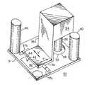
- FIG. 4is a perspective view of the platen of the system of FIG. 1 ;
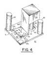
- FIG. 5is a side view of the system in accordance with a second embodiment of the present invention.
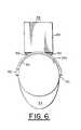
- FIG. 6is a front view of the system of FIG. 5 without the subject skin tissue
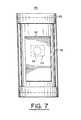
- FIG. 7is a plan view of the system of FIG. 5 without the subject skin tissue
- FIG. 8is a perspective view of the brace structure of the system of FIG. 5 with the upper lamination of the brace structure and confocal imaging head removed;
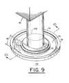
- FIG. 9is a perspective view of the system in accordance with a third embodiment of the present invention.
- FIG. 10is a cross-sectional view of the system along line 10 - 10 of FIG. 9 when the attachment of the system is not engaging skin tissue;
- FIG. 11is another cross-sectional view of the system along line 10 - 10 of FIG. 9 when the attachment of the system is engaging skin tissue.
- system 14including a rigid table 16 with a pad 17 on table surface 16 a upon which a patient 18 may lay flat.
- Pad 17may be composed of a vinyl-covered cell foam (such as CF 40100 Foam from EAR Specialty Composites of Indianapolis. Ind.) which deforms under the weight of patient 18 and remains deformed for a period of time after the patient has left the table.
- Table 16has two parallel rails 20 spaced apart from each other along two opposite sides of table 16 , and two parallel rails 22 spaced apart from each other. Rails 20 and 22 are perpendicular to each other, i.e., rails 20 extend in the x direction and rails 22 extend in the y direction.
- a platen 30 carrying a confocal imaging head 34is mounted in a mechanism provided by rails 20 and 22 for movably positioning head 34 to observe dermal tissue of interest in the body of patient 18 .
- This mechanismhas a carriage 25 supporting platen 30 .
- Carriage 25rides along rails 22 across table 16 (as indicated by bidirectional arrow x), and is locked in position with respect to rails 22 by a lock 28 , such as a locking screw.
- Rails 22 and its two spacers 23which connect rails 22 together, ride along rails 20 up or down table 16 (as indicated by bi-directional arrow y), and are locked in position with respect to rails 20 by a lock 24 , such as a locking screw.
- platen 30can then be moved by the operator in two orthogonal directions x and y over patient 18 and temporarily fixed in a desired position.
- Platen 30is a rigid structure having an upper surface 31 with a translation stage 36 which is mechanically coupled to a confocal imaging head 34 via support 36 a .
- Confocal imaging head 34has an objective lens 35 positioned over an orifice or opening 32 through platen 30 .
- Confocal imaging head 34 with objective lens 35are described in U.S. application Ser. No. 08/650,684, filed May 20, 1996, now U.S. Pat. No. 5,788,639, issued Aug. 4, 1998, and assigned to the same assignee as the present invention, and is herein incorporated by reference.
- Translation stage 36is movable in two orthogonal directions x′ and y′ (see arrows x′ and y′ in FIG. 4 ) to provide fine resolution positioning (a; compared with coarse positioning of platen 30 via rails 20 and 22 ) of imaging head 34 , and more specifically objective lens 35 , with respect to platen 30 over orifice 32 .
- the translation stage 36has cross rotating ball bearings (not shown) or cross piezoelectric position actuators to facilitate fine resolution movement in orthogonal directions x′ and y′.
- Manual stage micrometers 37 a and 37 badjust translation stage 36 in x′ and y′ directions, respectively. Micrometers 37 a and 37 b may be substituted by motors which are remotely controlled.
- a lock (not shown) on translation stage 36may be provided to temporarily fix the position of stage 30 , and consequently imaging head 22 , with respect to platen 30 .
- translation stage 36defines a means for fine resolution positioning of the objective lens over the orifice.
- an index matching plate 38may be positioned within orifice 32 in front of objective lens 35 to form a window which maintains the height stability of the tissue while presenting the edges of orifice 32 to the skin for stressing the tissue.
- Platen 30includes four vibration damping rods 40 at the four corners of platen 30 (for purposes of illustration only two rods 40 are shown in FIG. 4 ).
- Each damping rod 40has a lower end coupled to platen 30 and an upper end coupled to carriage 25 , as shown in FIGS. 1-3 .
- damping rods 40connect platen 30 to carriage 25 .
- Damping rods 40may be hydraulic type shock absorbers which when released allow platen 30 to gradually move from an up position to a down position upon the patient's skin 14 a (such as shown in FIG. 1 ) and also allow platen 30 to be moved from a down position back to an up position. Locking screws (not shown) on the damping rods 40 may fix the position of platen 30 with respect to carriage 25 in either up or down positions. Damping rods 40 thereby provide a means for moving platen 30 from an up position, in which the platen is spaced from patient 18 , to a down position onto surface 18 a of skin tissue of the patient.
- the operatormoves rails 22 (i.e., the rails upon which carriage 25 rides) along rails 20 to position platen 30 in the y direction, and moves carriage 25 along rails 22 to position platen 30 in the x-direction such that the volume of skin tissue of interest on patient 18 , such as a lesion, will be positioned within orifice 23 of the platen when platen 30 is in a down position.
- the operatoruses locks 24 and 28 described above, the operator locks carriage 25 with respect to rails 20 and 22 , thus fixing the position of platen 30 with respect to patient 18 .
- the operatorreleases damping rods 40 to allow platen 30 to gradually fall by the force of gravity onto the patient's skin.
- the skin lying within orifice 32 of platen 30bulges upwards into orifice 32 , thereby applying stress to the skin.
- This stressplaces the skin in orifice 32 preferably under tension, but may further push the skin up into orifice 32 by compression of skin beneath platen 30 .
- the stress applied to the skin in orifice 32is substantially due to the downward pressure or force of platen 30 at the edges of orifice 32 .
- springsmay be located within damping rods 40 to provide additional downward pressure onto the skin. The operator then controls the translation stage movement either directly or remotely to position objective lens 35 of imaging head 34 over area of tissue within orifice 32 desired to be imaged.
- the operatorenables optics within the confocal imaging head to confocally image horizontal, vertical, or angular sections through different planes of the tissue.
- the stress applied to the skin tissue in orifice 32stabilize the tissue reducing motion of the skin tissue with respect to confocal imaging head 34 , thereby stabilizing confocal images scanned by head 34 .
- Platen 30may have a paper pad 42 to provide a recording media, and a pen or marker 44 mechanically coupled to translation stage 36 by arm 43 such that pen 44 is suspended over pad 42 . Movement of translation stage 36 can thus be recorded by ink from the pen 44 on pad 32 .
- Thisallows the operator during confocal imaging by imaging head 34 to map the horizontal extent or borders of a lesion in the skin, since pen 44 transfers the motion of translation stage 36 on pad 43 by the fixed geometry which mechanically couples pen 44 to objective lens 23 via arm 43 , stage 36 , support 36 a and imaging head 34 .
- imaging head 34may be replaced by another pen to permit the operator to trace the extent of the lesion recorded on pad 32 onto the surface of the skin.
- index markson the skin surface with a pen, or other marking instrument, at notches (not shown) along the sides of orifice 32 . These index marks locate both orifice 32 and the relative position of objective lens 35 with respect to the skin surface when confocal imaging is performed. In subsequent examinations, orifice 32 and objective lens 35 can be aligned with these index marks to confocally image the same area of skin, and, for example, observe changes occurring in a skin lesion over time.
- FIGS. 5-8A second embodiment of the present invention is shown in FIGS. 5-8 having a system 58 .
- System 58includes a brace structure 50 having a rigid lower lamination 52 which is held stationary to the skin tissue 18 a of patient 18 by straps 54 .
- Lower lamination 52is shaped to approximate the curvature of a gross anatomical body part of the patient, such as part of the leg, torso, or arm, as shown in FIG. 5 .
- a bottom 52 a of lower lamination 52has an opening 53 , as shown in FIGS. 7 and 8 .
- Bottom 52 adefines a well 59 therein between ends 57 a and sides 57 b of lower lamination 52 .
- Ends 57 a and sides 57 bdefine a rigid frame 57 .
- ends 57 a and sides 57 bhave blind slots 55 within which an upper lamination 56 is captured.
- FIG. 8shows frame 57 of lower lamination 52 in which upper lamination 56 has been removed for
- Upper lamination 56is a curved rigid sheet parallel with lower lamination 52 , and has a confocal viewing window 58 ( FIG. 7 ) substantially smaller than opening 53 . Viewing window 58 may be positioned at a location over opening 53 by sliding upper lamination 56 over lower lamination 52 via slots 55 within frame 57 .
- a confocal imaging head 60is supported on brace structure 50 by gussets 62 ( FIG. 6 ) and has an objective lens (not shown) positioned for imaging through confocal viewing window 58 of upper lamination 56 .
- the windowmay contain a transparent plate for tissue height stabilization. Confocal imaging head 60 with the objective lens 35 are described in U.S. application Ser. No. 08/650,684, filed May 20, 1996, now U.S.
- Confocal imaging head 60is fixably attached to upper lamination 56 and slides therewith over lower lamination 52 .
- brace 50is first strapped by straps 54 over an anatomical feature, such as an arm, leg, or torso, in which the general skin tissue area to be confocally imaged bulges upward through opening 53 of bottom 52 a under the pressure from lower lamination 52 , thereby applying stress to the surface of the skin.
- This stresspreferably places the skin through opening 53 under tension, but may further push the skin up into opening 53 by compression of skin beneath lower lamination 52 .
- the stress applied to the skin in opening 53is substantially due to the pressure or force from lower lamination 52 to the skin tissue at the edges of opening 53 .
- the specific area of the skin to be confocally imagedis then positioned within confocal viewing window 58 by sliding upper lamination 56 over lower lamination 52 .
- Lower lamination 52provides a sliding surface for upper lamination 56 and slots 55 of frame 57 provide sufficient friction against upper lamination 56 to temporarily fix the position of upper lamination 56 with respect to lower lamination 52 and the skin tissue.
- Confocal imaging head 60is then attached to upper lamination 56 of brace 50 to position the confocal optics of head 60 , i.e., its objective lens, through confocal imagine window 58 .
- brace 50locates confocal imaging head 60 in fixed relationship with the skin tissue, and window 58 defines an aperture through brace 50 for imaging via optics of head 60 .
- imaging head 60By attaching imaging head 60 to upper lamination 56 , head 60 moves with motion of the skin tissue since such motion is transferred to head 60 via brace structure 50 . This reduces the relative motion of the tissue held under stress with respect to the confocal optics of imaging head 60 to minimize instability of the confocal images from imaging head 60 .
- Upper lamination 56may be moved to reposition the confocal imaging optics of head 60 through window 58 for confocal imaging of other areas of skin tissue within opening 53 .
- FIGS. 9-11A third embodiment of the present invention is shown in FIGS. 9-11 .
- This embodimentis provided by a tissue stabilization system 68 which includes an attachment 69 .
- the tissueis shown at 84 in FIGS. 10-11 as a layer of skin.
- Attachment 69includes a flexible diaphragm member 70 , a central circular window or plate member 72 , and a semi-rigid ring 74 .
- Diaphragm 70is composed of deformable rubber selected to be less compliant than tissue 84 .
- Diaphragm 70radially extends from window 72 outward to semi-rigid ring 74 .
- Ring 74may be composed of hard rubber, while window 72 may be composed of a material having an optical index approximately matching tissue 84 .
- Diaphragm 70has between ring 74 and window 72 an annular protruding section 75 (protruding in the direction of the arrow of FIG. 10 ). Section 75 defines outer and inner annular cavities 76 and 78 , respectively. Also, attachment 69 has a pair of vacuum lines 80 which each connects different ones of annular cavities 76 and 78 to a pneumatic pump which selectively creates suction between diaphragm 70 and the surface 84 a of tissue 84 . The size or diameter of system 68 and its attachment 69 may be appropriately dimensioned for the skin surface area to be confocally imaged through window 72 .
- System 68further includes a confocal imaging head 82 having an objective lens 83 positioned such that lens 83 is directed to window 72 of attachment 69 .
- Confocal imaging head 82 with objective lens 83are described in U.S. application Ser. No. 08/650,684, filed May 20, 1996, now U.S. Pat. No. 5,788,639, issued Aug. 4, 1998, and assigned to the same assignee as the present invention, and is herein incorporated by reference.
- Objective lens 83is shown in phantom lines in FIG. 9 , and the dotted lines in the figure represent the optical imaging paths between lens 83 and other confocal optics within imaging head 82 . For example, these optical imaging paths may be provided within an extending snout between head 82 and objective lens 83 .
- attachment 69is first placed over surface 84 a of tissue 84 such that diaphragm protruding section 75 is adjacent to surface 84 a , as shown in FIG. 10 .
- window 72is located over the area of tissue 84 to be confocally imaged, the air is evacuated via vacuum lines 80 from each cavity 76 and 78 . This creates suction which pulls tissue 84 up into cavities 76 and 78 , as shown in FIG. 11 .
- semi-rigid ring 74 and window 72are pulled downward onto surface 84 , and the tissue beneath window 72 is placed under stress, such as by tension or compression.
- attachment 69engages or adheres by suction to the surface 84 a of the tissue.
- objective lens 83 of confocal imaging head 82is placed against window 72 for confocal imaging of tissue 84 below window 72 , then the confocal optics within imaging head 60 are enabled to provide confocal images of horizontal, vertical and angular sections through different planes of the tissue.
- attachment 69may be fixedly attached to head 82 in front of its objective lens 83 prior to placing attachment 69 adjacent to the skin tissue. Since the tissue being confocally imaged is held under stress by attachment 69 under window 72 , the relative motion of this tissue with respect to the confocal optics within imaging head 82 is reduced, thereby stabilizing confocal images from head 82 .
- airis allowed to flow back into cavities 76 and 78 via vacuum lines 80 , allowing attachment 69 to disengage from the surface 84 a of the tissue.
- a liquid on the surface 84 a of the tissuemay be evacuated via vacuum lines 80 (in combination with or instead of air) from cavities 76 and 78 . Such a liquid may be applied to the surface 84 a of the tissue prior to placing attachment 69 over the surface.
- Each of the three embodiments of the present inventionis particularly suitable for imaging external tissue in different regions of the patient's body.
- the first embodimentmay be used for confocal imaging of skin tissue on the chest or back, while the second embodiment may be used, for gross anatomical features, such as the arm or leg, around which straps can hold brace structure 50 upon.
- the third embodimentis useful for smaller regions of the skin, particularly where there is no gross anatomical feature, or where the surface of the skin tissue in not substantially level, such as the cervix or forehead.
- Each of the above confocal imaging system embodimentsprovides a mechanism for maintaining an area of skin tissue being confocal imaged under a stressed configuration by tension or compression, thereby minimizing the motion of this area with respect to a confocal imaging head.
- the tissue being imagedis not skin as that term is commonly understood, but represents internal tissue of a patient. Internal tissues, for example which are surgically exposed, may be stabilized using the invention.
Landscapes
- Health & Medical Sciences (AREA)
- Life Sciences & Earth Sciences (AREA)
- Engineering & Computer Science (AREA)
- Animal Behavior & Ethology (AREA)
- Public Health (AREA)
- Pathology (AREA)
- Physics & Mathematics (AREA)
- Biomedical Technology (AREA)
- Heart & Thoracic Surgery (AREA)
- Medical Informatics (AREA)
- Molecular Biology (AREA)
- Surgery (AREA)
- Veterinary Medicine (AREA)
- General Health & Medical Sciences (AREA)
- Biophysics (AREA)
- Dermatology (AREA)
- Human Computer Interaction (AREA)
- Nuclear Medicine, Radiotherapy & Molecular Imaging (AREA)
- Radiology & Medical Imaging (AREA)
- Surgical Instruments (AREA)
- Microscoopes, Condenser (AREA)
- Measurement Of The Respiration, Hearing Ability, Form, And Blood Characteristics Of Living Organisms (AREA)
- Apparatus For Radiation Diagnosis (AREA)
- Laser Surgery Devices (AREA)
- Eye Examination Apparatus (AREA)
Abstract
Description
Claims (32)
Priority Applications (1)
| Application Number | Priority Date | Filing Date | Title |
|---|---|---|---|
| US11/784,128US8606343B2 (en) | 1996-10-18 | 2007-04-05 | System and method for confocal imaging within dermal tissue |
Applications Claiming Priority (4)
| Application Number | Priority Date | Filing Date | Title |
|---|---|---|---|
| US2884796P | 1996-10-18 | 1996-10-18 | |
| US08/942,431US6424852B1 (en) | 1996-10-18 | 1997-10-01 | System for confocal imaging within dermal tissue |
| US09/658,736US7225010B1 (en) | 1996-10-18 | 2000-09-11 | System and method for confocal imaging within dermal tissue |
| US11/784,128US8606343B2 (en) | 1996-10-18 | 2007-04-05 | System and method for confocal imaging within dermal tissue |
Related Parent Applications (1)
| Application Number | Title | Priority Date | Filing Date |
|---|---|---|---|
| US09/658,736DivisionUS7225010B1 (en) | 1996-10-18 | 2000-09-11 | System and method for confocal imaging within dermal tissue |
Publications (2)
| Publication Number | Publication Date |
|---|---|
| US20070287921A1 US20070287921A1 (en) | 2007-12-13 |
| US8606343B2true US8606343B2 (en) | 2013-12-10 |
Family
ID=21845806
Family Applications (5)
| Application Number | Title | Priority Date | Filing Date |
|---|---|---|---|
| US08/942,431Expired - LifetimeUS6424852B1 (en) | 1996-10-18 | 1997-10-01 | System for confocal imaging within dermal tissue |
| US09/658,736Expired - Fee RelatedUS7225010B1 (en) | 1996-10-18 | 2000-09-11 | System and method for confocal imaging within dermal tissue |
| US10/164,681Expired - Fee RelatedUS6937886B2 (en) | 1996-10-18 | 2002-06-07 | System for confocal imaging within dermal tissue |
| US11/081,181Expired - Fee RelatedUS8121670B2 (en) | 1996-10-18 | 2005-03-16 | System for confocal imaging within dermal tissue |
| US11/784,128Expired - Fee RelatedUS8606343B2 (en) | 1996-10-18 | 2007-04-05 | System and method for confocal imaging within dermal tissue |
Family Applications Before (4)
| Application Number | Title | Priority Date | Filing Date |
|---|---|---|---|
| US08/942,431Expired - LifetimeUS6424852B1 (en) | 1996-10-18 | 1997-10-01 | System for confocal imaging within dermal tissue |
| US09/658,736Expired - Fee RelatedUS7225010B1 (en) | 1996-10-18 | 2000-09-11 | System and method for confocal imaging within dermal tissue |
| US10/164,681Expired - Fee RelatedUS6937886B2 (en) | 1996-10-18 | 2002-06-07 | System for confocal imaging within dermal tissue |
| US11/081,181Expired - Fee RelatedUS8121670B2 (en) | 1996-10-18 | 2005-03-16 | System for confocal imaging within dermal tissue |
Country Status (4)
| Country | Link |
|---|---|
| US (5) | US6424852B1 (en) |
| EP (1) | EP1011441B1 (en) |
| AU (1) | AU4669697A (en) |
| WO (1) | WO1998017166A2 (en) |
Cited By (10)
| Publication number | Priority date | Publication date | Assignee | Title |
|---|---|---|---|---|
| US20100137710A1 (en)* | 1996-10-18 | 2010-06-03 | Zavislan James M | System for marking the locations of imaged tissue with respect to the surface of the tissue |
| US9677869B2 (en) | 2012-12-05 | 2017-06-13 | Perimeter Medical Imaging, Inc. | System and method for generating a wide-field OCT image of a portion of a sample |
| US9726647B2 (en) | 2015-03-17 | 2017-08-08 | Hemosonics, Llc | Determining mechanical properties via ultrasound-induced resonance |
| US10433784B2 (en) | 2014-05-05 | 2019-10-08 | Caliber Imaging & Diagnostics, Inc. | System and method for mapping the locations of captured confocal images of a lesion in skin tissue |
| US10539776B2 (en) | 2017-10-31 | 2020-01-21 | Samantree Medical Sa | Imaging systems with micro optical element arrays and methods of specimen imaging |
| US10577573B2 (en) | 2017-07-18 | 2020-03-03 | Perimeter Medical Imaging, Inc. | Sample container for stabilizing and aligning excised biological tissue samples for ex vivo analysis |
| US10928621B2 (en) | 2017-10-31 | 2021-02-23 | Samantree Medical Sa | Sample dishes for use in microscopy and methods of their use |
| US10962524B2 (en) | 2011-02-15 | 2021-03-30 | HomoSonics LLC | Characterization of blood hemostasis and oxygen transport parameters |
| US11609186B2 (en) | 2015-03-31 | 2023-03-21 | Samantree Medical Sa | Systems and methods for in-operating-theatre imaging of fresh tissue resected during surgery for pathology assessment |
| US11747603B2 (en) | 2017-10-31 | 2023-09-05 | Samantree Medical Sa | Imaging systems with micro optical element arrays and methods of specimen imaging |
Families Citing this family (65)
| Publication number | Priority date | Publication date | Assignee | Title |
|---|---|---|---|---|
| US20010041843A1 (en)* | 1999-02-02 | 2001-11-15 | Mark Modell | Spectral volume microprobe arrays |
| US6424852B1 (en)* | 1996-10-18 | 2002-07-23 | Lucid, Inc. | System for confocal imaging within dermal tissue |
| US7204832B2 (en) | 1996-12-02 | 2007-04-17 | Pálomar Medical Technologies, Inc. | Cooling system for a photo cosmetic device |
| US8182473B2 (en) | 1999-01-08 | 2012-05-22 | Palomar Medical Technologies | Cooling system for a photocosmetic device |
| US6517532B1 (en) | 1997-05-15 | 2003-02-11 | Palomar Medical Technologies, Inc. | Light energy delivery head |
| ATE409005T1 (en) | 1997-03-19 | 2008-10-15 | Lucid Inc | CELL SURGERY USING CONFOCAL MICROSCOPY |
| ES2226133T3 (en) | 1997-05-15 | 2005-03-16 | Palomar Medical Technologies, Inc. | DERMATOLOGICAL TREATMENT DEVICE. |
| ES2245506T3 (en) | 1998-03-12 | 2006-01-01 | Palomar Medical Technologies, Inc. | ELECTROMAGNETIC RADIATION APPLICATION SYSTEM ON SKIN. |
| AU5923299A (en)* | 1998-09-14 | 2000-04-03 | Lucid, Inc. | A system for marking the locations of imaged tissue with respect to the surface of the tissue |
| CA2356195A1 (en) | 1998-12-23 | 2000-06-29 | Medispectra, Inc. | Optical methods and systems for cervical screening |
| US7187810B2 (en) | 1999-12-15 | 2007-03-06 | Medispectra, Inc. | Methods and systems for correcting image misalignment |
| US7260248B2 (en) | 1999-12-15 | 2007-08-21 | Medispectra, Inc. | Image processing using measures of similarity |
| US6530882B1 (en)* | 2000-06-30 | 2003-03-11 | Inner Vision Imaging, L.L.C. | Endoscope having microscopic and macroscopic magnification |
| US6888319B2 (en) | 2001-03-01 | 2005-05-03 | Palomar Medical Technologies, Inc. | Flashlamp drive circuit |
| US7540869B2 (en) | 2001-12-27 | 2009-06-02 | Palomar Medical Technologies, Inc. | Method and apparatus for improved vascular related treatment |
| US20040133112A1 (en)* | 2002-03-08 | 2004-07-08 | Milind Rajadhyaksha | System and method for macroscopic and confocal imaging of tissue |
| WO2004000098A2 (en) | 2002-06-19 | 2003-12-31 | Palomar Medical Technologies, Inc. | Method and apparatus for treatment of cutaneous and subcutaneous conditions |
| CA2487987C (en) | 2002-06-19 | 2010-04-13 | Palomar Medical Technologies, Inc. | Method and apparatus for photothermal treatment of tissue at depth |
| US7469160B2 (en) | 2003-04-18 | 2008-12-23 | Banks Perry S | Methods and apparatus for evaluating image focus |
| US7136518B2 (en) | 2003-04-18 | 2006-11-14 | Medispectra, Inc. | Methods and apparatus for displaying diagnostic data |
| US7309867B2 (en)* | 2003-04-18 | 2007-12-18 | Medispectra, Inc. | Methods and apparatus for characterization of tissue samples |
| US7282723B2 (en) | 2002-07-09 | 2007-10-16 | Medispectra, Inc. | Methods and apparatus for processing spectral data for use in tissue characterization |
| US7459696B2 (en)* | 2003-04-18 | 2008-12-02 | Schomacker Kevin T | Methods and apparatus for calibrating spectral data |
| US6768918B2 (en) | 2002-07-10 | 2004-07-27 | Medispectra, Inc. | Fluorescent fiberoptic probe for tissue health discrimination and method of use thereof |
| EP2522294A2 (en) | 2002-10-23 | 2012-11-14 | Palomar Medical Technologies, Inc. | Phototreatment device for use with coolants and topical substances |
| US7149566B2 (en) | 2002-10-31 | 2006-12-12 | Manoa Medical, Inc. | Soft tissue orientation and imaging guide systems and methods |
| FR2858206B1 (en)* | 2003-07-28 | 2006-04-14 | Fabre Pierre Dermo Cosmetique | EXTENSIOMETER OF THE SKIN |
| US7309335B2 (en) | 2003-12-31 | 2007-12-18 | Palomar Medical Technologies, Inc. | Dermatological treatment with visualization |
| US20050177919A1 (en)* | 2004-02-04 | 2005-08-18 | Igal Kushnir | Medical garment |
| EP2301471A1 (en) | 2004-04-01 | 2011-03-30 | The General Hospital Corporation | Method and apparatus for dermatological treatment and tissue reshaping |
| US20050280892A1 (en)* | 2004-05-28 | 2005-12-22 | Nobuyuki Nagasawa | Examination method and examination apparatus |
| US7809618B2 (en)* | 2004-09-28 | 2010-10-05 | Diane Velona | Educational tuition securities system |
| US20060100523A1 (en)* | 2004-11-08 | 2006-05-11 | Ogle John S | Noninvasive blood vessel location device and method |
| DE102005043573A1 (en)* | 2005-04-07 | 2006-10-12 | Universität Duisburg-Essen | Device and method for optical examination of the human or animal body |
| US7856985B2 (en) | 2005-04-22 | 2010-12-28 | Cynosure, Inc. | Method of treatment body tissue using a non-uniform laser beam |
| CN101309631A (en) | 2005-09-15 | 2008-11-19 | 帕洛玛医疗技术公司 | Skin optical characterization device |
| US7864996B2 (en)* | 2006-02-17 | 2011-01-04 | Lucid, Inc. | System for macroscopic and confocal imaging of tissue |
| JP2007279387A (en) | 2006-04-06 | 2007-10-25 | Olympus Corp | Stabilizer for somatoscopy |
| US8260401B2 (en)* | 2006-07-26 | 2012-09-04 | University Of Rochester | Non-invasive in-vivo imaging of mechanoreceptors in skin using confocal microscopy |
| US7586957B2 (en) | 2006-08-02 | 2009-09-08 | Cynosure, Inc | Picosecond laser apparatus and methods for its operation and use |
| US7973925B2 (en)* | 2007-02-06 | 2011-07-05 | C8 Medisensors Inc. | Apparatus for stabilizing mechanical, thermal, and optical properties and for reducing the fluorescence of biological samples for optical evaluation |
| EP3229010A3 (en) | 2007-10-25 | 2018-01-10 | Washington University in St. Louis | Confocal photoacoustic microscopy with optical lateral resolution |
| US8620409B2 (en) | 2008-08-04 | 2013-12-31 | University Of Utah Research Foundation | Dye application for confocal imaging of cellular microstructure |
| US20100087806A1 (en)* | 2008-10-07 | 2010-04-08 | Vandolay, Inc. | Automated Cryogenic Skin Treatment |
| US9528966B2 (en)* | 2008-10-23 | 2016-12-27 | Washington University | Reflection-mode photoacoustic tomography using a flexibly-supported cantilever beam |
| WO2010080991A2 (en) | 2009-01-09 | 2010-07-15 | Washington University In St. Louis | Miniaturized photoacoustic imaging apparatus including a rotatable reflector |
| US9919168B2 (en) | 2009-07-23 | 2018-03-20 | Palomar Medical Technologies, Inc. | Method for improvement of cellulite appearance |
| US9086365B2 (en) | 2010-04-09 | 2015-07-21 | Lihong Wang | Quantification of optical absorption coefficients using acoustic spectra in photoacoustic tomography |
| US9795340B2 (en)* | 2010-12-13 | 2017-10-24 | National Taiwan University | Vacuum-pump sucker |
| US8997572B2 (en) | 2011-02-11 | 2015-04-07 | Washington University | Multi-focus optical-resolution photoacoustic microscopy with ultrasonic array detection |
| US8411265B2 (en) | 2011-06-14 | 2013-04-02 | C8 Medisensors Inc. | Apparatus for stabilizing mechanical, thermal, and optical properties and for reducing the fluorescence of biological samples for optical evaluation |
| ES2878548T3 (en) | 2012-02-26 | 2021-11-19 | Caliber Imaging & Diagnostics Inc | Tissue specimen stage for an optical sectioning microscope |
| EP2839552A4 (en) | 2012-04-18 | 2015-12-30 | Cynosure Inc | PICOSECOND LASER APPARATUS AND METHOD OF PROCESSING TARGET TISSUES USING THE SAME |
| EP2711758A1 (en)* | 2012-09-21 | 2014-03-26 | Mavig GmbH | Marking attachment for confocal microscopes |
| WO2014063005A1 (en) | 2012-10-18 | 2014-04-24 | Washington University | Transcranialphotoacoustic/thermoacoustic tomography brain imaging informed by adjunct image data |
| US10285757B2 (en) | 2013-03-15 | 2019-05-14 | Cynosure, Llc | Picosecond optical radiation systems and methods of use |
| WO2015077355A1 (en) | 2013-11-19 | 2015-05-28 | Washington University | Systems and methods of grueneisen-relaxation photoacoustic microscopy and photoacoustic wavefront shaping |
| US10568695B2 (en)* | 2016-09-26 | 2020-02-25 | International Business Machines Corporation | Surgical skin lesion removal |
| US11672426B2 (en) | 2017-05-10 | 2023-06-13 | California Institute Of Technology | Snapshot photoacoustic photography using an ergodic relay |
| WO2019165426A1 (en) | 2018-02-26 | 2019-08-29 | Cynosure, Inc. | Q-switched cavity dumped sub-nanosecond laser |
| EP3836831A4 (en) | 2018-08-14 | 2022-05-18 | California Institute of Technology | MULTIFOCAL PHOTOACOUSTIC MICROSCOPY THROUGH AN ERGODIC RELAY |
| WO2020051246A1 (en) | 2018-09-04 | 2020-03-12 | California Institute Of Technology | Enhanced-resolution infrared photoacoustic microscopy and spectroscopy |
| US11369280B2 (en) | 2019-03-01 | 2022-06-28 | California Institute Of Technology | Velocity-matched ultrasonic tagging in photoacoustic flowgraphy |
| WO2021092250A1 (en) | 2019-11-05 | 2021-05-14 | California Institute Of Technology | Spatiotemporal antialiasing in photoacoustic computed tomography |
| US11636591B2 (en) | 2020-06-18 | 2023-04-25 | Alibaba Group Holding Limited | Surface imaging using high incident angle of light rays |
Citations (42)
| Publication number | Priority date | Publication date | Assignee | Title |
|---|---|---|---|---|
| US4385634A (en) | 1981-04-24 | 1983-05-31 | University Of Arizona Foundation | Radiation-induced thermoacoustic imaging |
| DE3231483A1 (en) | 1982-08-25 | 1984-03-01 | Albert Prof. Dr. 3550 Marburg Huch | Arrangement for measurement of superficial capillaries |
| US4442844A (en) | 1981-08-28 | 1984-04-17 | Navach Joseph H | Method and apparatus for making physiological measurements |
| US4515165A (en) | 1980-02-04 | 1985-05-07 | Energy Conversion Devices, Inc. | Apparatus and method for detecting tumors |
| US4570638A (en) | 1983-10-14 | 1986-02-18 | Somanetics Corporation | Method and apparatus for spectral transmissibility examination and analysis |
| WO1988005284A1 (en) | 1987-01-22 | 1988-07-28 | Newer S.A. | Apparatus for determining an antisolar protection index |
| US4807979A (en)* | 1986-01-24 | 1989-02-28 | Geno Saccomanno | Microscope slide marking device |
| US5120953A (en) | 1988-07-13 | 1992-06-09 | Harris Martin R | Scanning confocal microscope including a single fibre for transmitting light to and receiving light from an object |
| US5146923A (en) | 1986-12-18 | 1992-09-15 | Dhawan Atam P | Apparatus and method for skin lesion examination |
| US5195522A (en) | 1990-11-30 | 1993-03-23 | Ivac Corporation | Tonometry sensor calibration apparatus |
| US5349961A (en) | 1983-10-14 | 1994-09-27 | Somanetics Corporation | Method and apparatus for in vivo optical spectroscopic examination |
| US5371368A (en) | 1992-07-23 | 1994-12-06 | Alfano; Robert R. | Ultrafast optical imaging of objects in a scattering medium |
| EP0683386A1 (en) | 1994-05-17 | 1995-11-22 | TOA MEDICAL ELECTRONICS CO., Ltd. | Non-invasive blood analyzer |
| JPH07333517A (en)* | 1994-06-07 | 1995-12-22 | Sumitomo Electric Ind Ltd | Microscope system with stage coordinate recording mechanism |
| US5524636A (en) | 1992-12-21 | 1996-06-11 | Artann Corporation Dba Artann Laboratories | Method and apparatus for elasticity imaging |
| WO1996021938A1 (en) | 1995-01-13 | 1996-07-18 | The General Hospital Corporation | Video-rate confocal scanning laser microscope |
| US5557452A (en) | 1995-02-06 | 1996-09-17 | University Of Hawaii | Confocal microscope system |
| US5598269A (en)* | 1994-05-12 | 1997-01-28 | Children's Hospital Medical Center | Laser guided alignment apparatus for medical procedures |
| US5606971A (en) | 1995-11-13 | 1997-03-04 | Artann Corporation, A Nj Corp. | Method and device for shear wave elasticity imaging |
| US5701902A (en) | 1994-09-14 | 1997-12-30 | Cedars-Sinai Medical Center | Spectroscopic burn injury evaluation apparatus and method |
| US5719700A (en) | 1991-10-11 | 1998-02-17 | L'oreal | Apparatus for in vivo observation of the microscopic structure of the skin or of a similar tissue |
| US5722398A (en) | 1994-11-15 | 1998-03-03 | Toa Medical Electronics Co., Ltd. | Apparatus for measuring concentration of hemoglobin and method for the same |
| US5730133A (en) | 1994-05-20 | 1998-03-24 | Dynamics Imaging, Inc. | Optical functional mamoscope |
| US5769076A (en) | 1995-05-02 | 1998-06-23 | Toa Medical Electronics Co., Ltd. | Non-invasive blood analyzer and method using the same |
| US5788639A (en) | 1995-07-13 | 1998-08-04 | Lucid Technologies, Inc. | Confocal imaging through thick dermal tissue |
| US5788634A (en) | 1993-12-07 | 1998-08-04 | Nihon Kohden Corporation | Multi purpose sensor |
| US5787887A (en) | 1993-11-24 | 1998-08-04 | Siemens Aktiengesellschaft | Apparatus for tissue examination using bidirectional transirradiation with light |
| US5833634A (en) | 1995-11-09 | 1998-11-10 | Uromed Corporation | Tissue examination |
| US5833633A (en) | 1992-12-21 | 1998-11-10 | Artann Laboratories | Device for breast haptic examination |
| US5840023A (en) | 1996-01-31 | 1998-11-24 | Oraevsky; Alexander A. | Optoacoustic imaging for medical diagnosis |
| US5842995A (en) | 1996-06-28 | 1998-12-01 | Board Of Regents, The Univerisity Of Texas System | Spectroscopic probe for in vivo measurement of raman signals |
| US5848177A (en) | 1994-12-29 | 1998-12-08 | Board Of Trustees Operating Michigan State University | Method and system for detection of biological materials using fractal dimensions |
| US5851181A (en) | 1996-08-30 | 1998-12-22 | Esc Medical Systems Ltd. | Apparatus for simultaneously viewing and spectrally analyzing a portion of skin |
| US5860967A (en) | 1993-07-21 | 1999-01-19 | Lucid, Inc. | Dermatological laser treatment system with electronic visualization of the area being treated |
| US5880880A (en) | 1995-01-13 | 1999-03-09 | The General Hospital Corp. | Three-dimensional scanning confocal laser microscope |
| US5999836A (en) | 1995-06-06 | 1999-12-07 | Nelson; Robert S. | Enhanced high resolution breast imaging device and method utilizing non-ionizing radiation of narrow spectral bandwidth |
| US6032071A (en) | 1994-12-01 | 2000-02-29 | Norbert Artner | Skin examination device |
| US6197575B1 (en) | 1998-03-18 | 2001-03-06 | Massachusetts Institute Of Technology | Vascularized perfused microtissue/micro-organ arrays |
| US6263233B1 (en) | 1995-07-13 | 2001-07-17 | Lucid, Inc. | Handheld imaging microscope |
| US6509161B1 (en) | 2000-02-29 | 2003-01-21 | Gentronix Limited | Green fluorescent protein |
| US6745067B1 (en) | 1998-09-14 | 2004-06-01 | Lucid, Inc. | System for marking the locations of imaged tissue with respect to the surface of the tissue |
| US6937886B2 (en) | 1996-10-18 | 2005-08-30 | Lucid, Inc. | System for confocal imaging within dermal tissue |
Family Cites Families (7)
| Publication number | Priority date | Publication date | Assignee | Title |
|---|---|---|---|---|
| US4281645A (en)* | 1977-06-28 | 1981-08-04 | Duke University, Inc. | Method and apparatus for monitoring metabolism in body organs |
| US4170987A (en)* | 1977-11-28 | 1979-10-16 | California Institute Of Technology | Medical diagnosis system and method with multispectral imaging |
| US5016173A (en)* | 1989-04-13 | 1991-05-14 | Vanguard Imaging Ltd. | Apparatus and method for monitoring visually accessible surfaces of the body |
| FR2719058B1 (en)* | 1994-04-22 | 1996-07-12 | Superba Sa | Machine for continuous dyeing of textile threads. |
| US5983120A (en)* | 1995-10-23 | 1999-11-09 | Cytometrics, Inc. | Method and apparatus for reflected imaging analysis |
| WO1998037811A1 (en)* | 1997-02-28 | 1998-09-03 | Electro-Optical Sciences, Inc. | Systems and methods for the multispectral imaging and characterization of skin tissue |
| US6993167B1 (en)* | 1999-11-12 | 2006-01-31 | Polartechnics Limited | System and method for examining, recording and analyzing dermatological conditions |
- 1997
- 1997-10-01USUS08/942,431patent/US6424852B1/ennot_activeExpired - Lifetime
- 1997-10-08WOPCT/US1997/017990patent/WO1998017166A2/enactiveApplication Filing
- 1997-10-08AUAU46696/97Apatent/AU4669697A/ennot_activeAbandoned
- 1997-10-08EPEP97945515Apatent/EP1011441B1/ennot_activeExpired - Lifetime
- 2000
- 2000-09-11USUS09/658,736patent/US7225010B1/ennot_activeExpired - Fee Related
- 2002
- 2002-06-07USUS10/164,681patent/US6937886B2/ennot_activeExpired - Fee Related
- 2005
- 2005-03-16USUS11/081,181patent/US8121670B2/ennot_activeExpired - Fee Related
- 2007
- 2007-04-05USUS11/784,128patent/US8606343B2/ennot_activeExpired - Fee Related
Patent Citations (48)
| Publication number | Priority date | Publication date | Assignee | Title |
|---|---|---|---|---|
| US4515165A (en) | 1980-02-04 | 1985-05-07 | Energy Conversion Devices, Inc. | Apparatus and method for detecting tumors |
| US4385634A (en) | 1981-04-24 | 1983-05-31 | University Of Arizona Foundation | Radiation-induced thermoacoustic imaging |
| US4442844A (en) | 1981-08-28 | 1984-04-17 | Navach Joseph H | Method and apparatus for making physiological measurements |
| DE3231483A1 (en) | 1982-08-25 | 1984-03-01 | Albert Prof. Dr. 3550 Marburg Huch | Arrangement for measurement of superficial capillaries |
| US4570638A (en) | 1983-10-14 | 1986-02-18 | Somanetics Corporation | Method and apparatus for spectral transmissibility examination and analysis |
| US5349961A (en) | 1983-10-14 | 1994-09-27 | Somanetics Corporation | Method and apparatus for in vivo optical spectroscopic examination |
| US4807979A (en)* | 1986-01-24 | 1989-02-28 | Geno Saccomanno | Microscope slide marking device |
| US5146923A (en) | 1986-12-18 | 1992-09-15 | Dhawan Atam P | Apparatus and method for skin lesion examination |
| WO1988005284A1 (en) | 1987-01-22 | 1988-07-28 | Newer S.A. | Apparatus for determining an antisolar protection index |
| CH669325A5 (en) | 1987-01-22 | 1989-03-15 | Newer Sa | |
| AU1104588A (en) | 1987-01-22 | 1988-08-10 | Newer S.A. | Apparatus for determining an antisolar protection index |
| US5120953A (en) | 1988-07-13 | 1992-06-09 | Harris Martin R | Scanning confocal microscope including a single fibre for transmitting light to and receiving light from an object |
| US5195522A (en) | 1990-11-30 | 1993-03-23 | Ivac Corporation | Tonometry sensor calibration apparatus |
| US5719700A (en) | 1991-10-11 | 1998-02-17 | L'oreal | Apparatus for in vivo observation of the microscopic structure of the skin or of a similar tissue |
| US5371368A (en) | 1992-07-23 | 1994-12-06 | Alfano; Robert R. | Ultrafast optical imaging of objects in a scattering medium |
| US5833633A (en) | 1992-12-21 | 1998-11-10 | Artann Laboratories | Device for breast haptic examination |
| US5524636A (en) | 1992-12-21 | 1996-06-11 | Artann Corporation Dba Artann Laboratories | Method and apparatus for elasticity imaging |
| US5860967A (en) | 1993-07-21 | 1999-01-19 | Lucid, Inc. | Dermatological laser treatment system with electronic visualization of the area being treated |
| US5787887A (en) | 1993-11-24 | 1998-08-04 | Siemens Aktiengesellschaft | Apparatus for tissue examination using bidirectional transirradiation with light |
| US5788634A (en) | 1993-12-07 | 1998-08-04 | Nihon Kohden Corporation | Multi purpose sensor |
| US5598269A (en)* | 1994-05-12 | 1997-01-28 | Children's Hospital Medical Center | Laser guided alignment apparatus for medical procedures |
| EP0683386A1 (en) | 1994-05-17 | 1995-11-22 | TOA MEDICAL ELECTRONICS CO., Ltd. | Non-invasive blood analyzer |
| US5730133A (en) | 1994-05-20 | 1998-03-24 | Dynamics Imaging, Inc. | Optical functional mamoscope |
| JPH07333517A (en)* | 1994-06-07 | 1995-12-22 | Sumitomo Electric Ind Ltd | Microscope system with stage coordinate recording mechanism |
| US5701902A (en) | 1994-09-14 | 1997-12-30 | Cedars-Sinai Medical Center | Spectroscopic burn injury evaluation apparatus and method |
| US5722398A (en) | 1994-11-15 | 1998-03-03 | Toa Medical Electronics Co., Ltd. | Apparatus for measuring concentration of hemoglobin and method for the same |
| US6032071A (en) | 1994-12-01 | 2000-02-29 | Norbert Artner | Skin examination device |
| US5848177A (en) | 1994-12-29 | 1998-12-08 | Board Of Trustees Operating Michigan State University | Method and system for detection of biological materials using fractal dimensions |
| WO1996021938A1 (en) | 1995-01-13 | 1996-07-18 | The General Hospital Corporation | Video-rate confocal scanning laser microscope |
| US5995283A (en) | 1995-01-13 | 1999-11-30 | General Hospital Corporation | Three-dimensional scanning confocal laser microscope |
| US5880880A (en) | 1995-01-13 | 1999-03-09 | The General Hospital Corp. | Three-dimensional scanning confocal laser microscope |
| US5557452A (en) | 1995-02-06 | 1996-09-17 | University Of Hawaii | Confocal microscope system |
| US5769076A (en) | 1995-05-02 | 1998-06-23 | Toa Medical Electronics Co., Ltd. | Non-invasive blood analyzer and method using the same |
| US5999836A (en) | 1995-06-06 | 1999-12-07 | Nelson; Robert S. | Enhanced high resolution breast imaging device and method utilizing non-ionizing radiation of narrow spectral bandwidth |
| US6263233B1 (en) | 1995-07-13 | 2001-07-17 | Lucid, Inc. | Handheld imaging microscope |
| US5788639A (en) | 1995-07-13 | 1998-08-04 | Lucid Technologies, Inc. | Confocal imaging through thick dermal tissue |
| US5833634A (en) | 1995-11-09 | 1998-11-10 | Uromed Corporation | Tissue examination |
| US5606971A (en) | 1995-11-13 | 1997-03-04 | Artann Corporation, A Nj Corp. | Method and device for shear wave elasticity imaging |
| US5840023A (en) | 1996-01-31 | 1998-11-24 | Oraevsky; Alexander A. | Optoacoustic imaging for medical diagnosis |
| US5842995A (en) | 1996-06-28 | 1998-12-01 | Board Of Regents, The Univerisity Of Texas System | Spectroscopic probe for in vivo measurement of raman signals |
| US5851181A (en) | 1996-08-30 | 1998-12-22 | Esc Medical Systems Ltd. | Apparatus for simultaneously viewing and spectrally analyzing a portion of skin |
| US6937886B2 (en) | 1996-10-18 | 2005-08-30 | Lucid, Inc. | System for confocal imaging within dermal tissue |
| US7225010B1 (en) | 1996-10-18 | 2007-05-29 | Lucid, Inc. | System and method for confocal imaging within dermal tissue |
| US7711410B2 (en) | 1996-10-18 | 2010-05-04 | Lucid, Inc. | System for marking the locations of imaged tissue with respect to the surface of the tissue |
| US20100137710A1 (en) | 1996-10-18 | 2010-06-03 | Zavislan James M | System for marking the locations of imaged tissue with respect to the surface of the tissue |
| US6197575B1 (en) | 1998-03-18 | 2001-03-06 | Massachusetts Institute Of Technology | Vascularized perfused microtissue/micro-organ arrays |
| US6745067B1 (en) | 1998-09-14 | 2004-06-01 | Lucid, Inc. | System for marking the locations of imaged tissue with respect to the surface of the tissue |
| US6509161B1 (en) | 2000-02-29 | 2003-01-21 | Gentronix Limited | Green fluorescent protein |
Non-Patent Citations (13)
| Title |
|---|
| Brumberg et al., "Hand-held contact microscope for medical applications," Soviet Journal of Optical Technology, Jan. 1974, vol. 41, No. 1. |
| Corcuff et al., In vivo Vision of the Human Skin with the Tandem Scanning Microscope, Dermatology, vol. 186, pp. 50-54, (1993). |
| Corcuff et al., Morphometry of human epidermis in vivo by real-time confocal microscopy, Arch Dermatol Res. 1993, 285, pp. 475-481. |
| Delaney et al., Fibre Optic Confocal Imaging (FOCI) for subsurface microscopy of the colon in vivo, J. Anat. 184, pp. 157-160, (1994). |
| Delaney et al., Novel Microscopy Using Fibre Optic Confocal Imaging and Its Suitability for Subsurface Blood Vessel Imaging in Vivo, Clinical and Experimental Pharmacology and Physiology, 20, pp. 197-198, (1993). |
| Jester et al., In-Vivo Real-Time Confocal Imaging, Journal of Electron Microscopy Technique, vol. 18, No. 1, pp. 50-60, May 1991. |
| Koester, C., Scanning mirror microscope with optical sectioning characteristics: applications in ophthalmology, Applied Optics, vol. 19, No. 11, pp. 1749-1757, 1980. |
| Machine Translation of JP7-333517A Dec. 1995.* |
| Maurice, D., A Scanning Slit Optical Microscope, Investigative Ophthalmology, vol. 13, No. 12, pp. 1033-1037, 1974. |
| Maurice, D., Cellular Membrane Activity in the Corneal Endothelium of the Intact Eye, Experientia, vol. 24, No. 11, pp. 1094-1095, 1968. |
| New, K. et al., In Vivo Imaging of Human Teeth and Skin Using Real-Time Confocal Microscopy, Scanning, vol. 13, pp. 369-372, 1991. |
| Office Action dated Aug. 1, 2011 of U.S. Appl. No. 12/658,036. |
| Rajadhyaksha, et al., "In Vivo Confocal Scanning Laser Microscopy of Human Skin: Melanin Provides Strong Contrast" The Journal of Investigative Dermatology, vol. 104, No. 6, Jun. 1995, pp. 1-7. |
Cited By (23)
| Publication number | Priority date | Publication date | Assignee | Title |
|---|---|---|---|---|
| US20100137710A1 (en)* | 1996-10-18 | 2010-06-03 | Zavislan James M | System for marking the locations of imaged tissue with respect to the surface of the tissue |
| US11680940B2 (en) | 2011-02-15 | 2023-06-20 | Hemosonics Llc | Characterization of blood hemostasis and oxygen transport parameters |
| US10962524B2 (en) | 2011-02-15 | 2021-03-30 | HomoSonics LLC | Characterization of blood hemostasis and oxygen transport parameters |
| US9677869B2 (en) | 2012-12-05 | 2017-06-13 | Perimeter Medical Imaging, Inc. | System and method for generating a wide-field OCT image of a portion of a sample |
| US10359271B2 (en) | 2012-12-05 | 2019-07-23 | Perimeter Medical Imaging, Inc. | System and method for tissue differentiation in imaging |
| US10433784B2 (en) | 2014-05-05 | 2019-10-08 | Caliber Imaging & Diagnostics, Inc. | System and method for mapping the locations of captured confocal images of a lesion in skin tissue |
| US12163925B2 (en) | 2015-03-17 | 2024-12-10 | Hemosonics Llc | Determining mechanical properties via ultrasound-induced resonance |
| US11656206B2 (en) | 2015-03-17 | 2023-05-23 | Hemosonics Llc | Determining mechanical properties via ultrasound-induced resonance |
| US10495613B2 (en) | 2015-03-17 | 2019-12-03 | Hemosonics, Llc | Determining mechanical properties via ultrasound-induced resonance |
| US11002712B2 (en) | 2015-03-17 | 2021-05-11 | Hemosonics Llc | Determining mechanical properties via ultrasound-induced resonance |
| US9726647B2 (en) | 2015-03-17 | 2017-08-08 | Hemosonics, Llc | Determining mechanical properties via ultrasound-induced resonance |
| US11828710B2 (en) | 2015-03-31 | 2023-11-28 | Samantree Medical Sa | Systems and methods for in-operating-theatre imaging of fresh tissue resected during surgery for pathology assessment |
| US11609186B2 (en) | 2015-03-31 | 2023-03-21 | Samantree Medical Sa | Systems and methods for in-operating-theatre imaging of fresh tissue resected during surgery for pathology assessment |
| US10577573B2 (en) | 2017-07-18 | 2020-03-03 | Perimeter Medical Imaging, Inc. | Sample container for stabilizing and aligning excised biological tissue samples for ex vivo analysis |
| US10894939B2 (en) | 2017-07-18 | 2021-01-19 | Perimeter Medical Imaging, Inc. | Sample container for stabilizing and aligning excised biological tissue samples for ex vivo analysis |
| US10928621B2 (en) | 2017-10-31 | 2021-02-23 | Samantree Medical Sa | Sample dishes for use in microscopy and methods of their use |
| US11609416B2 (en) | 2017-10-31 | 2023-03-21 | Samantree Medical Sa | Imaging systems with micro optical element arrays and methods of specimen imaging |
| US11181728B2 (en) | 2017-10-31 | 2021-11-23 | Samantree Medical Sa | Imaging systems with micro optical element arrays and methods of specimen imaging |
| US11747603B2 (en) | 2017-10-31 | 2023-09-05 | Samantree Medical Sa | Imaging systems with micro optical element arrays and methods of specimen imaging |
| US10816788B2 (en) | 2017-10-31 | 2020-10-27 | Samantree Medical Sa | Imaging systems with micro optical element arrays and methods of specimen imaging |
| US11966037B2 (en) | 2017-10-31 | 2024-04-23 | Samantree Medical Sa | Sample dishes for use in microscopy and methods of their use |
| US10539776B2 (en) | 2017-10-31 | 2020-01-21 | Samantree Medical Sa | Imaging systems with micro optical element arrays and methods of specimen imaging |
| US12429679B2 (en) | 2017-10-31 | 2025-09-30 | Samantree Medical Sa | Imaging systems with micro optical element arrays and methods of specimen imaging |
Also Published As
| Publication number | Publication date |
|---|---|
| US6937886B2 (en) | 2005-08-30 |
| WO1998017166A2 (en) | 1998-04-30 |
| US6424852B1 (en) | 2002-07-23 |
| EP1011441B1 (en) | 2011-07-20 |
| US20050171441A1 (en) | 2005-08-04 |
| EP1011441A4 (en) | 2000-06-28 |
| US20070287921A1 (en) | 2007-12-13 |
| EP1011441A2 (en) | 2000-06-28 |
| US20020151782A1 (en) | 2002-10-17 |
| US7225010B1 (en) | 2007-05-29 |
| WO1998017166B1 (en) | 1998-10-01 |
| US8121670B2 (en) | 2012-02-21 |
| AU4669697A (en) | 1998-05-15 |
| WO1998017166A3 (en) | 1998-08-06 |
Similar Documents
| Publication | Publication Date | Title |
|---|---|---|
| US8606343B2 (en) | System and method for confocal imaging within dermal tissue | |
| US5719700A (en) | Apparatus for in vivo observation of the microscopic structure of the skin or of a similar tissue | |
| JP4480397B2 (en) | Multi-modality medical imaging system and method using patient handling assembly | |
| JP2006504488A5 (en) | ||
| US20130102893A1 (en) | Medical image registration using a rigid inner body surface | |
| EP0821245A2 (en) | magnetic resonance imaging apparatus | |
| US5883937A (en) | X-ray diagnostic apparatus | |
| US4503552A (en) | Simple mounting structure for dental X-ray apparatus | |
| WO2006084059A2 (en) | Adjustable orthopedic positioning device and method of use | |
| US5978695A (en) | System for imaging mechanically stabilized tissue | |
| US6270506B1 (en) | Medical targeting apparatus | |
| US5063933A (en) | Magnetic resonance imaging apparatus | |
| JP2002148518A (en) | Apparatus for observing the microstructure of skin or similar tissue in vivo | |
| CN111631894A (en) | Artificial intelligence medical image auxiliary diagnosis equipment | |
| JPH07275240A (en) | Medical X-ray equipment | |
| CN215584138U (en) | MR lumbar vertebrae image auxiliary device and MR imaging equipment | |
| CN111198345A (en) | Animal Head Coil Device for Magnetic Resonance Imaging | |
| JPS63240834A (en) | CT scanner device | |
| CN215079876U (en) | Magnetic portal frame | |
| CN222367707U (en) | A medical X-ray imaging device for auxiliary fixation | |
| LU509753B1 (en) | Surgical platform suitable for spine radiographic imaging and spine radiographic imaging and mapping method | |
| CN219645743U (en) | Position fixing device for breast examination | |
| CN219516233U (en) | Shooting support of a laser speckle image collector | |
| JPH0723942A (en) | X-ray CT system | |
| CN212623539U (en) | Medical image projection device |
Legal Events
| Date | Code | Title | Description |
|---|---|---|---|
| AS | Assignment | Owner name:NORTHEAST LCD CAPITAL, LLC, MAINE Free format text:SECURITY AGREEMENT;ASSIGNOR:LUCID, INC.;REEL/FRAME:028533/0017 Effective date:20120705 | |
| STCF | Information on status: patent grant | Free format text:PATENTED CASE | |
| AS | Assignment | Owner name:LUCID TECHNOLOGIES, INC., NEW YORK Free format text:ASSIGNMENT OF ASSIGNORS INTEREST;ASSIGNOR:ZAVISLAN, JAMES M.;REEL/FRAME:037890/0249 Effective date:19970924 | |
| AS | Assignment | Owner name:LUCID, INC., NEW YORK Free format text:CHANGE OF NAME;ASSIGNOR:LUCID TECHNOLOGIES, INC.;REEL/FRAME:038051/0027 Effective date:19980518 | |
| AS | Assignment | Owner name:CALIBER IMAGING & DIAGNOSTICS, INC., NEW YORK Free format text:CHANGE OF NAME;ASSIGNOR:LUCID, INC.;REEL/FRAME:038226/0225 Effective date:20141120 | |
| REMI | Maintenance fee reminder mailed | ||
| FEPP | Fee payment procedure | Free format text:SURCHARGE FOR LATE PAYMENT, SMALL ENTITY (ORIGINAL EVENT CODE: M2554) | |
| MAFP | Maintenance fee payment | Free format text:PAYMENT OF MAINTENANCE FEE, 4TH YR, SMALL ENTITY (ORIGINAL EVENT CODE: M2551) Year of fee payment:4 | |
| AS | Assignment | Owner name:WESTERN ALLIANCE BANK, CALIFORNIA Free format text:SECURITY INTEREST;ASSIGNOR:CALIBER IMAGING & DIAGNOSTICS, INC.;REEL/FRAME:051094/0824 Effective date:20191120 | |
| FEPP | Fee payment procedure | Free format text:MAINTENANCE FEE REMINDER MAILED (ORIGINAL EVENT CODE: REM.); ENTITY STATUS OF PATENT OWNER: SMALL ENTITY | |
| LAPS | Lapse for failure to pay maintenance fees | Free format text:PATENT EXPIRED FOR FAILURE TO PAY MAINTENANCE FEES (ORIGINAL EVENT CODE: EXP.); ENTITY STATUS OF PATENT OWNER: SMALL ENTITY | |
| STCH | Information on status: patent discontinuation | Free format text:PATENT EXPIRED DUE TO NONPAYMENT OF MAINTENANCE FEES UNDER 37 CFR 1.362 | |
| FP | Lapsed due to failure to pay maintenance fee | Effective date:20211210 |