US8606199B2 - Control of switcher regulated power amplifier modules - Google Patents
Control of switcher regulated power amplifier modulesDownload PDFInfo
- Publication number
- US8606199B2 US8606199B2US13/611,094US201213611094AUS8606199B2US 8606199 B2US8606199 B2US 8606199B2US 201213611094 AUS201213611094 AUS 201213611094AUS 8606199 B2US8606199 B2US 8606199B2
- Authority
- US
- United States
- Prior art keywords
- signal
- power
- amplifier
- control
- switching
- Prior art date
- Legal status (The legal status is an assumption and is not a legal conclusion. Google has not performed a legal analysis and makes no representation as to the accuracy of the status listed.)
- Active
Links
- 230000001105regulatory effectEffects0.000titledescription3
- 238000000034methodMethods0.000claimsabstractdescription36
- 238000012546transferMethods0.000claimsdescription71
- 230000005540biological transmissionEffects0.000claimsdescription52
- 230000000670limiting effectEffects0.000claimsdescription33
- 230000004044responseEffects0.000claimsdescription30
- 230000006835compressionEffects0.000claimsdescription19
- 238000007906compressionMethods0.000claimsdescription19
- 238000012937correctionMethods0.000claimsdescription14
- 230000000694effectsEffects0.000claimsdescription12
- 238000003860storageMethods0.000claimsdescription10
- 238000012512characterization methodMethods0.000claimsdescription4
- 238000012885constant functionMethods0.000claimsdescription4
- 238000001514detection methodMethods0.000claims12
- 238000004891communicationMethods0.000abstractdescription85
- 230000003321amplificationEffects0.000abstractdescription25
- 238000003199nucleic acid amplification methodMethods0.000abstractdescription25
- 230000006870functionEffects0.000description75
- 238000013461designMethods0.000description16
- 238000010586diagramMethods0.000description10
- 230000008859changeEffects0.000description9
- 208000019300CLIPPERSDiseases0.000description6
- 208000021930chronic lymphocytic inflammation with pontine perivascular enhancement responsive to steroidsDiseases0.000description6
- 238000002955isolationMethods0.000description6
- 230000008569processEffects0.000description6
- 230000002441reversible effectEffects0.000description6
- 238000006243chemical reactionMethods0.000description5
- 238000012360testing methodMethods0.000description5
- 230000001276controlling effectEffects0.000description4
- 238000010295mobile communicationMethods0.000description4
- 230000003068static effectEffects0.000description4
- 230000001052transient effectEffects0.000description3
- 230000006399behaviorEffects0.000description2
- 230000007423decreaseEffects0.000description2
- 230000003247decreasing effectEffects0.000description2
- 238000005516engineering processMethods0.000description2
- 238000001914filtrationMethods0.000description2
- 238000012545processingMethods0.000description2
- 230000002829reductive effectEffects0.000description2
- 238000005070samplingMethods0.000description2
- 230000004913activationEffects0.000description1
- 230000002411adverseEffects0.000description1
- 238000004458analytical methodMethods0.000description1
- 238000013459approachMethods0.000description1
- 230000008901benefitEffects0.000description1
- 230000001413cellular effectEffects0.000description1
- 230000002301combined effectEffects0.000description1
- 239000002131composite materialSubstances0.000description1
- 230000008878couplingEffects0.000description1
- 238000010168coupling processMethods0.000description1
- 238000005859coupling reactionMethods0.000description1
- 230000007812deficiencyEffects0.000description1
- 230000001934delayEffects0.000description1
- 230000001419dependent effectEffects0.000description1
- 239000000446fuelSubstances0.000description1
- 238000009434installationMethods0.000description1
- 238000004519manufacturing processMethods0.000description1
- 238000005259measurementMethods0.000description1
- 230000004048modificationEffects0.000description1
- 238000012986modificationMethods0.000description1
- 230000002085persistent effectEffects0.000description1
- 238000003825pressingMethods0.000description1
- 230000009467reductionEffects0.000description1
- 230000035945sensitivityEffects0.000description1
- 230000005236sound signalEffects0.000description1
- 230000001360synchronised effectEffects0.000description1
- 230000002194synthesizing effectEffects0.000description1
- 230000007704transitionEffects0.000description1
Images


Classifications
- H—ELECTRICITY
- H04—ELECTRIC COMMUNICATION TECHNIQUE
- H04B—TRANSMISSION
- H04B1/00—Details of transmission systems, not covered by a single one of groups H04B3/00 - H04B13/00; Details of transmission systems not characterised by the medium used for transmission
- H04B1/02—Transmitters
- H04B1/04—Circuits
- H04B1/0475—Circuits with means for limiting noise, interference or distortion
- H—ELECTRICITY
- H03—ELECTRONIC CIRCUITRY
- H03F—AMPLIFIERS
- H03F1/00—Details of amplifiers with only discharge tubes, only semiconductor devices or only unspecified devices as amplifying elements
- H03F1/02—Modifications of amplifiers to raise the efficiency, e.g. gliding Class A stages, use of an auxiliary oscillation
- H03F1/0205—Modifications of amplifiers to raise the efficiency, e.g. gliding Class A stages, use of an auxiliary oscillation in transistor amplifiers
- H03F1/0211—Modifications of amplifiers to raise the efficiency, e.g. gliding Class A stages, use of an auxiliary oscillation in transistor amplifiers with control of the supply voltage or current
- H03F1/0216—Continuous control
- H03F1/0222—Continuous control by using a signal derived from the input signal
- H03F1/0227—Continuous control by using a signal derived from the input signal using supply converters
- H—ELECTRICITY
- H03—ELECTRONIC CIRCUITRY
- H03F—AMPLIFIERS
- H03F3/00—Amplifiers with only discharge tubes or only semiconductor devices as amplifying elements
- H03F3/20—Power amplifiers, e.g. Class B amplifiers, Class C amplifiers
- H03F3/24—Power amplifiers, e.g. Class B amplifiers, Class C amplifiers of transmitter output stages
- H—ELECTRICITY
- H03—ELECTRONIC CIRCUITRY
- H03G—CONTROL OF AMPLIFICATION
- H03G3/00—Gain control in amplifiers or frequency changers
- H03G3/004—Control by varying the supply voltage
- H—ELECTRICITY
- H03—ELECTRONIC CIRCUITRY
- H03G—CONTROL OF AMPLIFICATION
- H03G3/00—Gain control in amplifiers or frequency changers
- H03G3/20—Automatic control
- H03G3/30—Automatic control in amplifiers having semiconductor devices
- H03G3/3036—Automatic control in amplifiers having semiconductor devices in high-frequency amplifiers or in frequency-changers
- H03G3/3042—Automatic control in amplifiers having semiconductor devices in high-frequency amplifiers or in frequency-changers in modulators, frequency-changers, transmitters or power amplifiers
- H—ELECTRICITY
- H04—ELECTRIC COMMUNICATION TECHNIQUE
- H04W—WIRELESS COMMUNICATION NETWORKS
- H04W88/00—Devices specially adapted for wireless communication networks, e.g. terminals, base stations or access point devices
- H04W88/02—Terminal devices
- H—ELECTRICITY
- H03—ELECTRONIC CIRCUITRY
- H03F—AMPLIFIERS
- H03F1/00—Details of amplifiers with only discharge tubes, only semiconductor devices or only unspecified devices as amplifying elements
- H03F1/02—Modifications of amplifiers to raise the efficiency, e.g. gliding Class A stages, use of an auxiliary oscillation
- H—ELECTRICITY
- H03—ELECTRONIC CIRCUITRY
- H03F—AMPLIFIERS
- H03F1/00—Details of amplifiers with only discharge tubes, only semiconductor devices or only unspecified devices as amplifying elements
- H03F1/34—Negative-feedback-circuit arrangements with or without positive feedback
- H—ELECTRICITY
- H04—ELECTRIC COMMUNICATION TECHNIQUE
- H04B—TRANSMISSION
- H04B1/00—Details of transmission systems, not covered by a single one of groups H04B3/00 - H04B13/00; Details of transmission systems not characterised by the medium used for transmission
- H04B1/02—Transmitters
- H04B1/04—Circuits
- H04B2001/0408—Circuits with power amplifiers
- H04B2001/0433—Circuits with power amplifiers with linearisation using feedback
- H—ELECTRICITY
- H04—ELECTRIC COMMUNICATION TECHNIQUE
- H04B—TRANSMISSION
- H04B1/00—Details of transmission systems, not covered by a single one of groups H04B3/00 - H04B13/00; Details of transmission systems not characterised by the medium used for transmission
- H04B1/02—Transmitters
- H04B1/04—Circuits
- H04B2001/0408—Circuits with power amplifiers
- H04B2001/045—Circuits with power amplifiers with means for improving efficiency
Definitions
- This descriptionrelates generally to wireless communication devices and more particularly to control of switcher regulated power amplifier using input drive.
- Handheld wireless communication devicesare powered by one or more internal batteries. A major performance criterion for such devices is their battery life, and a large portion of battery power is consumed in a power amplification block of the device's transmitter.
- a switched mode power supplywhich provides the supply voltage to a power amplifier in the power amplification block, is used to reduce overall power consumption.
- thisrequires careful control of the switched mode power supply to achieve optimal power savings.
- many conventional designsuse a fixed-step, or continuous control technique for controlling the switched mode power supply.
- both of these techniquesmay result in sub-optimal power savings, may be more cumbersome to calibrate, and may have an adverse affect on the output signal's compression artifacts. With most designs, the compression artifacts are very low compared to the signal power until the supply voltage provided to the power amplifier approaches its transmit power limit at which point the compression artifacts increase.
- FIG. 1is a block diagram of an exemplary embodiment of a wireless communications device
- FIG. 2is a block diagram of an exemplary embodiment of a communication subsystem component of the mobile device of FIG. 1 ;
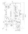
- FIG. 3is a block diagram of an exemplary embodiment of a portion of a power management block and an amplification block of the communications subsystem of the wireless communications device;
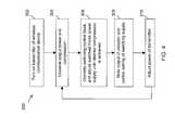
- FIG. 4is a flow chart diagram of an exemplary method that can be used for finding appropriate values for a switching control transfer function for a switch control block of the power management block;
- FIG. 5is a block diagram of an exemplary embodiment of a power limit controller of the power management block.
- a wireless communications deviceis a two-way communications device with advanced data communication capabilities having the capability to communicate with other computer systems.
- the wireless communications devicemay also include the capability for voice communications.
- itmay be referred to as a data messaging device, a two-way pager, a cellular telephone with data messaging capabilities, a wireless Internet appliance, or a data communications device (with or without telephony capabilities).
- the wireless communications devicecommunicates with other devices through a network of transceiver stations.
- the wireless communications device 100comprises a number of components, such as a control unit 102 which controls the overall operation of the wireless communications device 100 .
- the control unit 102may be a microprocessor or a microcontroller. Any commercially available microcontroller, such as a microcontroller available from ARM, Motorola, Intel and the like may be used for the control unit 102 .
- the communication subsystem 104receives messages from and sends messages to a wireless network 180 .
- the communication subsystem 104may be configured in accordance with CDMA2000 standards, or with Global System for Mobile Communication (GSM) and General Packet Radio Services (GPRS) standards.
- GSMGlobal System for Mobile Communication
- GPRSGeneral Packet Radio Services
- the GSM/GPRS wireless networkis used worldwide and it is expected that these standards will eventually be superseded by the Enhanced Data GSM Environment (EDGE) and Universal Mobile Telecommunications Service (UMTS) standards. New standards are still being defined, but it is believed that they will have similarities to the network behaviour described herein, and it will also be understood that the device is intended to use any other suitable standards that are developed in the future.
- the wireless link connecting the communications subsystem 104 with the network 180represents one or more different Radio Frequency (RF) channels, operating according to defined protocols specified for CDMA2000 or GSM/GPRS communications. With the network protocols, these channels are capable of supporting both circuit switched voice communications and packet switched data communications.
- RFRadio Frequency
- the control unit 102also interacts with additional subsystems such as a Random Access Memory (RAM) 106 , a flash memory 108 , a display 110 , an auxiliary input/output (I/O) subsystem 112 , a data port 114 , a keyboard 116 , a speaker 118 , a microphone 120 , a short-range communications subsystem 122 and other device subsystems 124 .
- RAMRandom Access Memory
- flash memory 108a flash memory
- I/Oauxiliary input/output subsystem
- data port 114a data port 114
- keyboard 116a keyboard 116
- speaker 118a speaker
- microphone 120a microphone
- a short-range communications subsystem 122a short-range communications subsystem 122
- the keyboard 116may be a telephone-type keypad, an alphanumeric keyboard or some other suitable keypad.
- the display 110 and the keyboard 116may be used for both communication-related functions, such as entering a text message for transmission over the network 180 , and device-resident functions such as a calculator or task list.
- Operating system software, and other various algorithms, used by the control unit 102is typically stored in a persistent store such as the flash memory 108 , which may alternatively be a read-only memory (ROM) or similar storage element (not shown).
- ROMread-only memory
- the operating system, specific device applications, or parts thereofmay be temporarily loaded into a volatile store such as the RAM 106 .
- the wireless communications device 100may send and receive communication signals over the network 180 after required network registration or activation procedures have been completed.
- Network accessis associated with a subscriber or user of the wireless communications device 100 .
- SIMSubscriber Identity Module
- R-UIMRemovable User Identity Module
- the SIM card or R-UIM 126is one type of a conventional “smart card” that is used to identify a subscriber of the wireless communications device 100 and to personalize the wireless communications device 100 , among other things.
- user identification informationcan also be programmed into flash memory 108 .
- Servicesmay include: web browsing and messaging such as email, voice mail, Short Message Service (SMS), and Multimedia Messaging Services (MMS). More advanced services may include: point of sale, field service and sales force automation.
- the wireless communications device 100is a battery-powered device and includes a battery interface 132 for receiving one or more rechargeable batteries 130 .
- the battery interface 132is coupled to a regulator (not shown) which assists the battery 130 in providing supply power V+ to the wireless communications device 100 .
- a regulatornot shown
- future power source technologiessuch as micro fuel cells may provide the power to the wireless communications device 100 .
- the control unit 102in addition to its operating system functions, enables execution of software applications on the wireless communications device 100 .
- a set of applications which control basic device operations, including data and voice communication applicationswill normally be installed on the wireless communications device 100 during its manufacture.
- Another application that may be loaded onto the wireless communications device 100may be a personal information manager (PIM).
- PIMhas the ability to organize and manage data items of interest to a subscriber, such as, but not limited to, e-mail, calendar events, voice mails, appointments, and task items.
- a PIM applicationhas the ability to send and receive data items via the wireless network 180 .
- PIM data itemsare seamlessly integrated, synchronized, and updated via the wireless network 180 with the wireless communications device subscriber's corresponding data items stored and/or associated with a host computer system.
- This functionalitycreates a mirrored host computer on the wireless communications device 100 with respect to such items. This is especially advantageous where the host computer system is the wireless communications device subscriber's office computer system.
- Additional applicationsmay also be loaded onto the wireless communications device 100 through the network 180 , the auxiliary I/O subsystem 112 , the data port 114 , the short-range communication subsystem 122 , or any other suitable device subsystem 124 .
- This flexibility in application installationincreases the functionality of the wireless communications device 100 and may provide enhanced on-device functions, communication-related functions, or both.
- secure communication applicationsmay enable electronic commerce functions and other such financial transactions to be performed using the wireless communications device 100 .
- the data port 114enables a subscriber to set preferences through an external device or software application and extends the capabilities of the mobile device 100 by providing for information or software downloads to the mobile device 100 other than through a wireless communication network.
- the alternate download pathmay, for example, be used to load an encryption key onto the mobile device 100 through a direct and thus reliable and trusted connection to provide secure device communication.
- the short-range communication subsystem 122provides for communication between the wireless communications device 100 and different systems or devices, without the use of the network 180 .
- the subsystem 122may include an infrared device and associated circuits and components for short-range communication.
- Examples of short-range communicationmay include standards developed by the Infrared Data Association (IrDA), Bluetooth, and the 802.11 family of standards developed by IEEE.
- a received signalsuch as a text message, an e-mail message, or web page download will be processed by the communications subsystem 104 and input to the control unit 102 .
- the control unit 102will then process the received signal for output to the display 110 or alternatively to the auxiliary I/O subsystem 112 .
- a subscribermay also compose data items, such as e-mail messages, for example, using the keyboard 116 in conjunction with display 110 and possibly auxiliary I/O subsystem 112 .
- the auxiliary subsystem 112may include devices such as: a touch screen, mouse, track ball, infrared fingerprint detector, or a roller wheel with dynamic button pressing capability.
- the keyboard 116may be an alphanumeric keyboard and/or telephone-type keypad.
- a composed itemmay be transmitted over the network 150 through the communication subsystem 104 .
- the overall operation of the wireless communications device 100is substantially similar, except that most of the received signals are output to the speaker 118 , and most of the signals for transmission are transduced by microphone 120 .
- Alternative voice or audio I/O subsystemssuch as a voice message recording subsystem, may also be implemented on the wireless communications device 100 .
- voice or audio signal outputis accomplished primarily through the speaker 118 , the display 110 may also be used to provide additional information such as the identity of a calling party, duration of a voice call, or other voice call related information.
- the communication subsystem 104comprises a receiver 150 , a transmitter 152 , one or more embedded or internal antenna elements 154 , 156 , Local Oscillators (LOs) 158 , and a processing module such as a Digital Signal Processor (DSP) 160 .
- LOsLocal Oscillators
- DSPDigital Signal Processor
- the particular design of the communication subsystem 104is dependent upon the network 180 in which the mobile device 100 is intended to operate, thus it should be understood that the design illustrated in FIG. 2 serves only as one example.
- Signals received by the antenna 154 through the network 180are input to the receiver 150 , which may perform such common receiver functions as signal amplification, frequency down conversion, filtering, channel selection, and analog-to-digital (A/D) conversion.
- A/D conversion of a received signalallows more complex communication functions such as demodulation and decoding to be performed in the DSP 160 .
- signals to be transmittedare processed, including modulation and encoding, by the DSP 160 .
- DSP-processed signalsare input to the transmitter 152 for digital-to-analog (D/A) conversion, frequency up conversion, filtering, amplification and transmission over the network 180 via the antenna 156 .
- the DSP 160not only processes communication signals, but also provides for receiver and transmitter control. For example, the gains applied to communication signals in the receiver 150 and transmitter 180 may be adaptively controlled through automatic gain control algorithms implemented in the DSP 160 .
- the wireless link between the mobile device 100 and the network 180may contain one or more different channels, typically different RF channels, and associated protocols used between the mobile device 100 and the network 180 .
- An RF channelis a limited resource that must be conserved, typically due to limits in overall bandwidth and limited battery power of the mobile device 100 .
- the transmitter 152When the mobile device 100 is fully operational, the transmitter 152 is typically keyed or turned on only when it is sending to the network 180 and is otherwise turned off to conserve resources. Similarly, the receiver 150 is periodically turned off to conserve power until it is needed to receive signals or information (if at all) during designated time periods.
- the various embodiments described hereinrelate to a power management block that can be used in the transmitter 152 of the communication subsystem 104 .
- the power management blockprovides improved control for the gain control signal provided to a pre-amplifier and the supply voltage provided to a power amplifier.
- the pre-amplifier and the power amplifierare both in a power amplification block of the transmitter 152 .
- the power expended by the power amplifieris optimized by employing a continuous control in which at least one feedback loop is employed to take into account various characteristics of certain components of the transmitter including the pre-amplifier and the power amplifier as well as various control signals.
- the structure and processing methodology employed by the power management blockalso results in constant code domain performance, as will be explained in further detail below.
- the designerIn communication systems that employ orthogonal code channels to combine and separate various streams of data, the designer must be careful not to accidentally combine, leak or add noise to the different channels by distorting the composite signal.
- the final amplifierusually the power amplifier
- the power amplifieris the device most likely to be driven into non-linear operation. This is especially true when power saving techniques are used. If the degree to which the power amplifier is compressed varies considerably during its range of operation, it is possible that the undesirable effects in the code domain will be present at some power levels and not others. This makes pre-compensation of the various code channels impossible unless one has the means to vary the compensation as the power demands are changed.
- a power amplifier with nearly constant compressionwill aid in the overall design of a transmitter with constant code domain performance and help simplify the baseband design without sacrificing power efficiency.
- the transmitter 152includes a power management block 202 , a detector 203 , a coupler 205 , a power amplification block 204 , an isolator 209 and an output coupler 211 .
- the isolator 209 and the output coupler 211are optional as is described further below.
- the duplexer 260is also connected to the receiver 150 (not shown).
- the power management block 202includes a power limit control block 207 , a switching regulator control block 208 , a switched mode power supply 210 , a compensating control block 212 , and a summer 213 .
- the power amplification block 204includes a pre-amplifier 214 , and a power amplifier 216 .
- the output coupler 211can be fed to a detector for power limiting for some cases.
- the power limit control block 207the compensating control block 212 , the summer 213 and the TX_lim control signal 224 are optional in some embodiments.
- the AGC signal 222is provided as the gain control signal 230 to the pre-amplifier 214 .
- the power limit control loop and the compensating loopcan be used separately. These loops are discussed in further detail below.
- the wireless communications device 100generates a data signal that is to be transmitted using the transmitter 152 .
- the data signalis typically a comparatively low frequency signal that is generally referred to as a baseband signal.
- the baseband signalis processed by various components (not shown but commonly known to those skilled in the art) of the communication subsystem 104 and mixed with a carrier signal having a substantially higher frequency to produce a transmission signal 225 .
- the transmission signal 225is amplified by the power amplification block 204 to produce an amplified transmission signal 227 for wireless transmission.
- the amplified transmission signal 227is then sent through the isolator 209 , the output coupler 211 , and the duplexer 260 to be radiated by the antenna 156 .
- the isolator 209protects the power amplification block 204 from reflections or other signal energy that comes from the downstream components, such as the antenna 156 .
- the isolator 209can sometimes be used to stabilize the performance of the duplexer 260
- the pre-amplifier 214is a variable gain amplifier that produces a pre-amplified transmission signal 229 .
- the gain of the pre-amplifier 214is varied to provide a first amount of gain depending on the desired power level for the amplified transmission signal 227 .
- the gain of the pre-amplifier 214is dictated by a gain control signal 230 provided by the power limit control block 207 .
- the power amplifier 216then amplifies the pre-amplified transmission signal 229 to provide the remainder of the required gain.
- a filter(not shown) may optionally be added after the pre-amplifier 214 for removing noise that is introduced into the pre-amplified transmission signal 229 by the pre-amplifier 214 and prior stages of the wireless communications device 100 . A person skilled in the art will be capable of selecting appropriate parameters for this filter.
- the power amplifier 216requires a supply voltage signal 232 with a magnitude that is sufficient so that the amplified transmission signal 227 can be produced with at most a maximum level of acceptable distortion. If the power amplifier 216 is always operating with the same level of acceptable distortion, then a fixed correction of the corresponding baseband data can be done to counteract the distortion while saving power. Accordingly, when the amplified transmission signal 227 is at any power within the transmitter's dynamic range, the power amplifier 216 should have constant headroom to ensure that the amplified transmission signal 227 is at most, always distorted in the same fashion.
- the amplified transmission signal 227is rarely at the maximum level mentioned above and is usually at a much lower power level.
- the excess headroom between the supply voltage 232 provided to the power amplifier 216 and the magnitude of the amplified transmission signal 227is dissipated as heat.
- the switched mode power supply 210is controlled by the switching regulator control block 208 to minimize the headroom but allow the power amplifier 216 to produce the amplified transmission signal 227 with the instantaneous maximum power that is required for transmission.
- a trim signal 220is a control signal that is provided to the power management block 202 by the control unit 102 .
- the trim signal 220is used to remove unit-to-unit variation during factory calibration of the wireless communications device 100 .
- the variationis due to offsets caused by part variation for the components used to build the transmitter 152 and the control loops.
- the trim signal 220trims or reduces variations caused by these offsets/tolerances. This can be done by sampling the output of the switched mode power supply 210 during operation and adjusting the value for the trim signal 220 to obtain acceptable performance.
- the compression artifacts of the transmitter 152can be measured and the value of the trim signal 220 adjusted until the desired amount of distortion is observed.
- the trim signal 220can be optional in some designs depending on the tolerance stackup.
- a detector 203senses the pre-amplified transmission signal 229 , which is the input drive for the power amplifier 216 , via a coupler 205 .
- the detector 203then produces a detected pre-amp output signal 221 .
- the detector 203can be an approximation to a true RMS detector with a linear scaled output. However, detectors having other forms of output, including a log output, may also be utilized.
- the location of the detector 203results in loop stability and power savings by not coupling with the output of the power amplifier 216 to sense the amplified transmission signal 227 .
- Gain expansion of the power amplifier 216would result in a control system with right hand poles, if the detector 203 is placed where it can be influenced by the gain expansion (i.e. on the output side of the power amplifier 216 ). With the detector 203 at the output of the power amplifier 216 , an increase in power, caused by gain expansion or maybe noise, for example, would cause the detected output to increase and drive up the supply voltage signal 232 . The resulting gain expansion would further increase the detected power. The process would then escalate. This is avoided by placing the detector 203 at the output of the pre-amplifier 214 .
- a person skilled in the artcan select the appropriate coupler 205 to use with the detector 203 . This selection process will be based on parameters such as the type of power amplifier 216 , tuning of the various control blocks in the power management block 202 , and intended overall performance targets for the power management block 202 .
- a directional couplercan be used for the coupler 205 , but a resistive tap may also be used if the pre-amplifier 214 has sufficient reverse isolation.
- the detected pre-amp output signal 221 and the trim signal 220are provided to the power management block 202 to limit the output power of the amplification block 204 . This is done by using these signals, as well as other information discussed below, to perform at least one of adjusting the gain of the pre-amplifier 214 and controlling the switched mode power supply 210 to provide the supply voltage signal 232 at a certain level.
- the main source of variation in the transmitter designis not due to the thermal characteristics of the power amplifier 216 but rather the variations in the thermal and frequency characteristics of the pre-amplifier 214 , which are poor. Consequently, by detecting the output power 229 of the pre-amplifier 214 , most of the variation in the transmitter 152 can be removed while decreasing the power losses in the transmitter 152 .
- the switching regulator control block 208controls the switched mode power supply 210 to provide the supply voltage signal 232 in an optimal fashion based on the trim signal 220 and the detected pre-amp output signal 221 .
- the switch control block 208applies a switching control transfer function to the detected pre-amp output signal 221 and the trim signal 220 to generate a switching supply control signal 228 to control the switched mode power supply 210 .
- itmay be desirable to filter certain high frequency noise components from the supply voltage signal 232 .
- the switched mode power supply 210may be a DC-DC switch converter. However, a broad class of devices may be utilized as the switched mode power supply 210 as long as the output voltage, current, efficiency and noise requirements of the amplification block 204 are met.
- the switching regulator control block 208can provide control values to the switched mode power supply 210 to hold the power amplifier 216 in a state of constant compression.
- code domain powerrefers to the relative power to noise ratio of the code channel in question (the other channels are orthogonal and appear like noise).
- Static compensationrefers to setting the code domain correction to compensate for the characteristics of the hardware but not for varying power.
- the switching control transfer functionis derived from a characterization of the response of the detector 203 , control curves of the switched mode power supply 210 , and the response of the power amplifier 216 to input drive. These values are captured by method 300 .
- FIG. 4shown therein is a flow chart diagram of an exemplary method 300 that can be used for determining appropriate values for the switching control transfer function for the switching regulator control block 208 .
- the method 300is performed on several wireless communication devices and the test results are aggregated to form the switching control transfer function used by the switching regulator control block 208 .
- the method 300begins at step 302 at which the transmitter 152 is turned on.
- the amplified transmission signal 227 and the compression of the power amplifier 216are observed.
- the switching regulator control block 208is overridden, and the switched mode power supply 210 is adjusted until the desired compression is achieved for the power amplifier 216 .
- Step 306sometimes jumps directly (not shown) to step 310 if the voltage adjustment perturbs the operating power too much.
- the output of the detector 203i.e. the detected pre-amp output signal 221
- the control setting of the switched mode power supply 210are noted in a data table at step 308 .
- the power of the transmitter 152is adjusted and steps 304 to 310 are repeated until enough data points are obtained.
- the switching control transfer functioncan be generated by looking at several different output power levels for the power amplifier 216 , and decreasing the supply voltage signal for of these levels until an acceptable minimum level of headroom is obtained for each power level. This provides a first relationship between the power level of the power amplifier 216 and the level of the supply voltage signal 232 . These different power levels are then related to the level of input drive (i.e. the output of the detector 203 ) while the supply voltage signal 232 is held at the minimum level just discovered for each power level to obtain a relationship between the level of input drive and the power level of the power amplifier 216 . These two relations are then combined to define the switching control transfer function between the output of the detector 203 and the output of the switched mode power supply 210 . The step response of the switching control transfer function can then be observed, either through modeling or actual testing, and certain parameters of the transfer function are adjusted to obtain acceptable timing.
- the data points generated through the method 300are then used to derive the optimal switching control transfer function for the switching regulator control block 208 .
- An option at this pointis to employ some interpolation between the measured points if so desired. While the method 300 generates static values for obtaining the switching control transfer function of the switching regulator control block 208 , the method 300 can be modified where the transmitter power is stepped so that dynamic characteristics are observed. At this point, an optional correction can be added for the time responses of the power management and amplification blocks 202 and 204 . This can be done in either hardware or software.
- the steps to perform thisare: 1) measure the step response of the system, 2) analyze the shape of the response to determine the compensation needed for the transfer functions in order to meet timing requirements, 3) apply the compensation and test the system, and 4) go back to step one if necessary and repeat until the performance is satisfactory.
- This processis fairly iterative as one sometimes finds some undesired side effects during testing.
- the switching control transfer functioncan then be defined at this point by looking at the step response of the power management and amplification blocks 202 and 204 and generating the appropriate inverse.
- the switching control transfer function employed by the switching regulator control block 208can be realized with hardware by using a filter with a linear, first-order low pass function and an offset.
- the filteris offset a bit to compensate for the response of the switcher/other circuits which don't operate properly at 0 volts.
- Implementation as a filtercan be done by taking the desired time response of the switching control transfer function, applying the Laplace transform to it, then synthesizing the filter based on the poles and zeros that are generated.
- the switching control transfer functioncan also be realized with software by using a look-up table.
- the response time of the switching control transfer functionis taken into consideration since the time response of the entire transmitter 152 is subject to regulatory requirements for the relationship between power and time which is network dependant. As such, the response of each block is considered since, for instance, sloppy performance in the switched mode power supply 210 means that more compensation is needed elsewhere. Time response is also a factor when software is used to implement the switching control transfer function. With software, the analysis is done assuming discrete time steps. Time response for software depends in part on the guaranteed latency of the software used to do the computations and/or lookups. On a processor with many applications running concurrently time response depends on: 1) code efficiency, and 2) the operating system, which can ensure guaranteed latencies when executing real time code. In general, the timing of the components is adjusted to provide a best fit to the timing requirements that are stipulated by the standard and network providers. The value for one timing parameter may need to be traded off against the value for another timing parameter.
- the gain control signal 230is set by the power limit control block 207 based on various inputs.
- An automatic gain control (AGC) signal 222 and a transmit limit (TX_lim) control signal 224are provided by the control unit 102 . Alternatively, these signals can be provided by a processor in the communication subsystem 104 if one exists.
- the TX_lim control signal 224specifies the maximum allowable power of the output of the power amplifier 216 .
- the AGC 222is modified by the output of the compensating control block 212 .
- the power limit control block 207also receives the detected pre-amp output signal 221 , and combines these signals to reduce the input drive to the power amplifier 216 by controlling the gain of the pre-amplifier 214 . The effect of reduced input drive is a reduction in the power of the amplified transmission signal 227 .
- the power limit control block 207includes a summer 402 , a clipper 404 , an integrator 406 , a power limiting transfer function 408 , and a second summer 410 .
- the power limit control block 207can anticipate an over power condition before it occurs and provide appropriate values for the gain control signal 230 to prevent the over power condition from occurring. This is based on the selection of particular values for the power limiting transfer function 408 , and by examining both the power error signal (i.e. the output of summer 402 ) and the rate of change of the power error signal (i.e.
- the rate of change of these signalsis related to the rate of change of the output of the detector 203 . If there is a high rate of change, there is likely to be an overshoot in the output power and an over power condition will result.
- the power error signalis obtained when the summer 402 subtracts the TX_lim signal 224 from the detected pre-amp output signal 221 . This difference is then passed sequentially through the clipper 404 , the integrator 406 , and the power limiting transfer function 408 to produce the error signal 412 .
- the clipper 404produces a clipped power error signal by converting all negative input values to zero, and passing positive values with an adjustment factor to account for the amount of correction deemed necessary to correct for the worst AGC error. Accordingly, the output of the clipper 404 is zero when the TX_lim signal 224 has a larger amplitude than the detected pre-amp output signal 221 .
- the output value of the clipper 404is equal to the amplitude difference between the detected pre-amp output signal 221 and the TX_lim signal 224 multiplied by an adjustment factor when the pre-amp output signal 221 is larger than the TX_lim signal 224 .
- the adjustment factoris used for scaling purposes to compensate for the sensitivity of the various components that are used. Without the clipper 404 , the power limit control block 242 would force the transmitter 152 to run at maximum power irrespective of the value of the AGC signal 222 .
- the integrator 406then integrates the clipped power error signal to provide an integrated power error signal (to achieve zero residual error in the transmitted power when the power limit control block 207 settles).
- the integrator 406can be implemented in hardware or software.
- the power limiting transfer function 408has a linear term and a first-order derivative term.
- the power limiting transfer function 408processes the integrated power error signal to detect an over power condition before it occurs.
- the power control loopincluding the switching regulator control block 208 and the switched mode power supply 210 , may not respond quickly enough on its own.
- This functionalityis provided by the various blocks in the power limit control block 207 including the power limiting transfer function 408 .
- the power limiting transfer function 408is chosen to get the desired transient performance of the power limit control block 207 .
- the power limiting transfer function 408also compensates for the behavior of the pre-amplifier 214 and other delays in the transmitter 152 . This can be done by applying prior knowledge of the different shaped power ramps to the control of the transmission power limit.
- the term “power ramp”refers to the relationship between power and time that is used to transition between different power levels. The knowledge of the desired shape, i.e. time response, allows for a more accurate design of the power limiting transfer function.
- the error signal 412is subtracted from the modified AGC signal 223 by the summer 410 to produce the gain control signal 230 to control the gain of the pre-amplifier 214 .
- the error signalhas a value of 0 and the gain control signal 230 is the modified AGC signal 223 .
- the modified AGC signal 223is generated by subtracting the output of the compensating control block 212 from the AGC signal 222 .
- the power limiting transfer function 408can be generated by selecting various values for the detected signal 221 , thereby testing various levels of over power with respect to the value of the transmit power control signal TX_lim 224 , and selecting values for the transfer function such that the level of the error signal 412 is adjusted so that the gain control signal 230 results in an acceptable level of input drive provided by the output of the pre-amplifier 214 . This sets the steady state characteristics of the power limiting transfer function 408 . The transient characteristics of the power limiting transfer function 408 are then observed by looking at the step response of the power limiting transfer function 408 . The values of the power limiting transfer function 408 are then adjusted so that the overshoot and the settling time of the step response are acceptable. In designs that include the switching control loop, the compensating loop, and the power limiting loop, the switching control transfer function and the compensating transfer function are selected and tuned first before tuning the power limiting transfer function.
- Calibration difficultiescome from the gain variation of the power amplifier 216 when the magnitude of the supply voltage signal 232 is changed. As the magnitude of the supply voltage signal 232 is increased, the gain of the power amplifier 216 also increases. In previous control schemes, the supply voltage signal 232 was controlled as a function of the AGC signal 222 . As the AGC signal 222 increases, the gain of the power amplifier 216 increases predictably but the output increases much more rapidly at certain points in the curve. This is due to the combined effect of increased pre-driver gain and the gain change in the power amplifier 216 due to the supply voltage signal 232 . Accordingly, kinks in the control curve can be eliminated by applying additional compensation to the AGC signal 222 and providing the pre-amplifier 214 with a modified gain control signal 230 .
- the topology shown of the power management block 204 in FIG. 3is designed to address the deficiencies in conventional switcher control schemes.
- the power management block 204employs a compensating feedback loop to create a linear relationship between the AGC signal 222 and the power of the amplified transmission signal 227 .
- the compensating feedback loopincludes the compensating control block 212 and the summer 213 .
- the compensating control block 212is an estimator that samples the supply voltage signal 232 at the output of switched mode power supply 210 and translates the supply voltage signal 232 into a gain correction signal 234 .
- the gain correction signalis then subtracted from the AGC signal 222 via the summer 213 to produce a modified gain control signal 223 .
- the compensating feedback loopacts to null the ill effects introduced by varying the magnitude of the supply voltage signal 232 to the power amplifier 216 .
- a compensating transfer functioncan be used to translate a value for the supply voltage signal 232 to a value for the gain correction signal 234 .
- the relationship between the gain and the supply voltage signal 232 for the power amplifier 216is determined for several power amplifiers. Once an average relationship has been obtained it is inversed, taking into account some average characteristics of the pre-amplifier 214 , such as the control slope of the pre-amplifier 214 , to produce the compensating transfer function such that there is a linear relationship between the gain and the supply voltage signal 232 .
- One characteristic of the pre-amplifier 214 to consideris the average gain versus control voltage curve. The thermal characteristics can be compensated for at top power by matching the characteristics of the detector and transmitter chain.
- the compensating transfer functionis selected, the transient properties are examined by looking at the step response to make sure that it falls within acceptable limits.
- the compensating transfer functionis selected and tuned after the switching control transfer function has been selected and tuned.
- the parameters for the power limit control block 207are set high to not have an effect on selecting and tuning the compensating transfer function.
- the compensating transfer functionmay be implemented in software by a lookup table or in hardware using a hardware filter.
- the supply voltage signal 232 and its rate of changeis used to determine a value for the gain correction signal 234 .
- the rate of change of the supply voltage signal 232can be used to anticipate the state that the power amplifier 216 will be in next because it takes some time for the other circuits to adjust. In a more advanced design one can monitor other bias parameters.
- the Laplace transformis applied to the time response or impulse response that corresponds to the compensating transfer function, and the filter is then synthesized based on the poles and zeros that are generated by the Laplace transform operation.
- the selection of the compensating transfer functionallows for compensation not only of static gain changes but also dynamic variation due to lags in the power management control and power amplification blocks 202 and 204 .
- the compensating transfer functionhas a linear term and a first order derivative term.
- the effect of the compensating feedback loopis to linearize the relationship between the power of the amplified transmission signal 227 and the AGC signal 222 for the transmitter 152 . Another result is that the compensating feedback loop decreases or postpones saturation effects for this relationship. Also, separating the power limiting function from the compensating control function decreases the accuracy requirements of the compensating control block 212 .
- the power limiting transfer function 408 and the compensating control transfer functioncan be implemented in hardware with a filter.
- these transfer functionsmay be implemented with software (i.e. as a look-up table).
- the detector 203By placing the detector 203 after the pre-amplifier 214 and before the power amplifier 216 , it is possible to eliminate the isolator 209 and output coupler 211 . In contrast, if the detector 203 was placed at the output of the power amplifier 216 , the isolator 209 and/or output coupler 211 would be required to prevent reflected power from being sensed by the detector 203 . Further, there would be power losses in the amplified transmission signal 227 due to the sampling done by the coupler 205 if it was placed at the output of the power amplifier 216 .
- the isolator 209 and the output coupler 211can be removed since the reverse isolation of the power amplifier 216 prevents reflected power from reaching the detector 203 .
- the reverse isolation of the power amplifier 216is indicated by the S 12 parameter which is the ratio of the power at the input of the power amplifier 216 to the power at the output of the power amplifier 216 when no input signal is provided to the power amplifier 216 and power is injected at the output of the power amplifier 216 .
- a good reverse isolationcan be achieved by controlling the drain gate capacitance of the final gain stage of the power amplifier 216 (for FET power amplifiers) or the collector base capacitance of the final gain stage of the power amplifier 216 (for HBT power amplifiers).
- the removal of the isolator 209 and the output coupler 211results in a cost/space savings due to implementing the transmitter 152 with a reduced number of components.
- the removal of the isolator 209 and the output coupler 211eliminates additional components where power may be diverted or dissipated between the power amplification block 204 and the antenna 156 , which reduces the amount of power loss in the amplified transmission signal 227 before it reaches the antenna 156 .
- the power amplifier 216must be matched to the duplexer 260 to prevent load-induced power changes (especially if the isolator 209 is removed). Reflected power at the output of the power amplifier 216 as a result of load shifts can cause the forward power to change by upsetting the operating point of the power amplifier 216 . Also, the reflected power can sometimes disturb the input of the power amplifier 216 if the reverse isolation is poor. However, with good reverse isolation and matching to the duplexer 260 , the isolator 209 and the output coupler 211 can be removed without incurring the usual maximum output power accuracy penalties.
- the architecture of the power management block 202 along with the location of the detector 203results in: 1) accurate, rate independent power limiting (due to a combination of the power limiting transfer function 408 and the detector choice resulting in an expanded upper range), 2) linearization of the AGC curve versus transmission power for the amplification block 204 , and 3) almost constant power amplifier compression versus transmitter power. Further, each transfer function is tuned in an appropriate manner related to its functionality and the transfer functions used in the various blocks are different from one another.
- the structure and method described hereinallow for the operation of the power amplifier 216 in constant compression independent of the power of the transmitter 152 . This results in: a) optimal power savings since the power amplifier 216 is provided with a minimum of supply voltage as described previously, and b) constant code domain performance.
- the architecture of the transmitter 152also allows for lower losses between the power amplifier 216 and the antenna 156 without incurring power accuracy penalties.
- the power management block 204can be divided into three subcomponents: a switching regulator control loop, a compensating feedback loop and a power limiting feedback loop.
- the switching regulator control loopincludes the coupler 205 , the detector 203 , the switching regulator control block 208 , and the switched mode power supply 210 .
- the compensating feedback loopincludes the components of the switching regulator control loop as well as the compensating control block 212 , and the summer 213 and receives inputs from the AGC control signal 222 and the TX_lim control signal 224 .
- the power limiting feedback loopincludes the coupler 205 , the detector 203 , and the power limit control block 207 and receives inputs from the output of the summer 213 and the TX_lim control signal 224 .
- At least one embodiment described hereinprovides a transmitter for a wireless communications device.
- the transmittercomprises a power amplification block comprising a pre-amplifier configured to amplify a transmission signal to produce a pre-amplified transmission signal; and a power amplifier coupled to the pre-amplifier and configured to amplify the pre-amplified transmission signal to produce an amplified transmission signal.
- the transmitterfurther comprises a detector coupled to the output of the pre-amplifier and configured to provide a detected pre-amp output signal; and a power management block.
- the power management blockcomprises a switching regulator control block configured to generate a switching supply control signal based on the detected pre-amp output signal; and a switched mode power supply coupled to the switching regulator control block and configured to generate a supply voltage signal based on the switching supply control signal and provide the supply voltage signal to the power amplifier.
- a mobile communication devicecomprising a main processor configured to control the operation of the mobile communication device; and a communication subsystem connected to the main processor, the communication subsystem being configured to send and receive data.
- the communication subsystemcomprises a power amplification block, a detector, and a power management block.
- the power amplification blockcomprises a pre-amplifier configured to amplify a transmission signal to produce a pre-amplified transmission signal; and a power amplifier coupled to the pre-amplifier and configured to amplify the pre-amplified transmission signal to produce an amplified transmission signal.
- the detectoris coupled to the output of the pre-amplifier and configured to provide a detected pre-amp output signal.
- the power management blockcomprises a switching regulator control block configured to generate a switching supply control signal based on the detected pre-amp output signal; and a switched mode power supply coupled to the switching regulator control block and configured to generate a supply voltage signal based on the switching supply control signal and provide the supply voltage signal to the power amplifier.
- At least one embodiment described hereinprovides a method of providing a supply voltage signal to a power amplification block of a transmitter, the power amplification block including a pre-amplifier and a power amplifier.
- the methodcomprises detecting the output of the pre-amplifier to provide a detected pre-amp output signal; generating a switching supply control signal based on the detected pre-amp output signal; and generating the supply voltage signal by providing the switching supply control signal to a switched mode power supply.
Landscapes
- Engineering & Computer Science (AREA)
- Power Engineering (AREA)
- Computer Networks & Wireless Communication (AREA)
- Signal Processing (AREA)
- Transmitters (AREA)
- Amplifiers (AREA)
- Control Of Amplification And Gain Control (AREA)
Abstract
Description
Claims (21)
Priority Applications (1)
| Application Number | Priority Date | Filing Date | Title |
|---|---|---|---|
| US13/611,094US8606199B2 (en) | 2006-06-14 | 2012-09-12 | Control of switcher regulated power amplifier modules |
Applications Claiming Priority (5)
| Application Number | Priority Date | Filing Date | Title |
|---|---|---|---|
| US81335206P | 2006-06-14 | 2006-06-14 | |
| US11/763,068US7907920B2 (en) | 2006-06-14 | 2007-06-14 | Control of switcher regulated power amplifier modules |
| US12/784,971US8160517B2 (en) | 2006-06-14 | 2010-05-21 | Control of switcher regulated power amplifier modules |
| US13/351,328US8295792B2 (en) | 2006-06-14 | 2012-01-17 | Control of switcher regulated power amplifier modules |
| US13/611,094US8606199B2 (en) | 2006-06-14 | 2012-09-12 | Control of switcher regulated power amplifier modules |
Related Parent Applications (1)
| Application Number | Title | Priority Date | Filing Date |
|---|---|---|---|
| US13/351,328ContinuationUS8295792B2 (en) | 2006-06-14 | 2012-01-17 | Control of switcher regulated power amplifier modules |
Publications (2)
| Publication Number | Publication Date |
|---|---|
| US20130012147A1 US20130012147A1 (en) | 2013-01-10 |
| US8606199B2true US8606199B2 (en) | 2013-12-10 |
Family
ID=38831370
Family Applications (4)
| Application Number | Title | Priority Date | Filing Date |
|---|---|---|---|
| US11/763,068Active2029-11-19US7907920B2 (en) | 2006-06-14 | 2007-06-14 | Control of switcher regulated power amplifier modules |
| US12/784,971ActiveUS8160517B2 (en) | 2006-06-14 | 2010-05-21 | Control of switcher regulated power amplifier modules |
| US13/351,328ActiveUS8295792B2 (en) | 2006-06-14 | 2012-01-17 | Control of switcher regulated power amplifier modules |
| US13/611,094ActiveUS8606199B2 (en) | 2006-06-14 | 2012-09-12 | Control of switcher regulated power amplifier modules |
Family Applications Before (3)
| Application Number | Title | Priority Date | Filing Date |
|---|---|---|---|
| US11/763,068Active2029-11-19US7907920B2 (en) | 2006-06-14 | 2007-06-14 | Control of switcher regulated power amplifier modules |
| US12/784,971ActiveUS8160517B2 (en) | 2006-06-14 | 2010-05-21 | Control of switcher regulated power amplifier modules |
| US13/351,328ActiveUS8295792B2 (en) | 2006-06-14 | 2012-01-17 | Control of switcher regulated power amplifier modules |
Country Status (9)
| Country | Link |
|---|---|
| US (4) | US7907920B2 (en) |
| EP (1) | EP2027651B1 (en) |
| JP (2) | JP5185115B2 (en) |
| KR (1) | KR101010042B1 (en) |
| CN (1) | CN101341653B (en) |
| AU (1) | AU2007260548B2 (en) |
| BR (1) | BRPI0702890B1 (en) |
| CA (1) | CA2623941C (en) |
| WO (1) | WO2007143844A1 (en) |
Cited By (3)
| Publication number | Priority date | Publication date | Assignee | Title |
|---|---|---|---|---|
| US8670503B2 (en) | 2004-02-20 | 2014-03-11 | Blackberry Limited | Method and apparatus for improving power amplifier efficiency in wireless communication systems having high peak to average power ratios |
| US8873675B2 (en) | 2002-12-02 | 2014-10-28 | Blackberry Limited | Method and apparatus for optimizing transmitter power efficiency |
| US9276545B2 (en) | 2010-07-23 | 2016-03-01 | Blackberry Limited | Method of power amplifier switching power control using post power amplifier power detection |
Families Citing this family (43)
| Publication number | Priority date | Publication date | Assignee | Title |
|---|---|---|---|---|
| KR101010042B1 (en) | 2006-06-14 | 2011-01-21 | 리서치 인 모션 리미티드 | Improved Control of Switcher-Adjusted Power Amplifier Modules |
| US7873119B2 (en)* | 2006-06-14 | 2011-01-18 | Research In Motion Limited | Input drive control for switcher regulated power amplifier modules |
| US8761305B2 (en) | 2006-06-14 | 2014-06-24 | Blackberry Limited | Input drive control for switcher regulated power amplifier modules |
| WO2008072134A1 (en)* | 2006-12-12 | 2008-06-19 | Koninklijke Philips Electronics N.V. | A high efficiency modulating rf amplifier |
| US8212541B2 (en) | 2008-05-08 | 2012-07-03 | Massachusetts Institute Of Technology | Power converter with capacitive energy transfer and fast dynamic response |
| TWI359559B (en)* | 2008-08-07 | 2012-03-01 | Ind Tech Res Inst | Power amplifier system and control method and cont |
| JP5255986B2 (en)* | 2008-10-20 | 2013-08-07 | 株式会社日立ハイテクノロジーズ | Patterned media inspection method and inspection apparatus |
| EP3447910B1 (en) | 2008-11-11 | 2020-12-16 | Massachusetts Institute Of Technology | An asymmetric multilevel outphasing architecture for rf amplifiers |
| KR101350288B1 (en)* | 2009-04-27 | 2014-01-23 | 후아웨이 테크놀러지 컴퍼니 리미티드 | A power control method and apparatus |
| US8483633B2 (en)* | 2010-07-23 | 2013-07-09 | Motorola Solutions, Inc. | Method and apparatus for alarming in a power supply modulated system |
| US8417199B2 (en) | 2010-07-23 | 2013-04-09 | Motorola Solutions, Inc. | Method and apparatus for improving efficiency in a power supply modulated system |
| US8615208B2 (en) | 2010-11-02 | 2013-12-24 | Crestcom, Inc. | Transmitter linearized in response to signal magnitude derivative parameter and method therefor |
| US8489047B2 (en)* | 2010-11-02 | 2013-07-16 | Crestcom, Inc. | Transmitter linearized using bias deviation gain adjustment and method therefor |
| US10389235B2 (en) | 2011-05-05 | 2019-08-20 | Psemi Corporation | Power converter |
| US8725218B2 (en)* | 2011-03-25 | 2014-05-13 | R2 Semiconductor, Inc. | Multimode operation DC-DC converter |
| EP4318909A3 (en) | 2011-05-05 | 2024-03-06 | PSEMI Corporation | Dc-dc converter with modular stages |
| US10680515B2 (en) | 2011-05-05 | 2020-06-09 | Psemi Corporation | Power converters with modular stages |
| US9882471B2 (en) | 2011-05-05 | 2018-01-30 | Peregrine Semiconductor Corporation | DC-DC converter with modular stages |
| KR101753738B1 (en) | 2011-09-22 | 2017-07-07 | 한국전자통신연구원 | Analog digital converter and method for saving power thereof |
| US8743553B2 (en) | 2011-10-18 | 2014-06-03 | Arctic Sand Technologies, Inc. | Power converters with integrated capacitors |
| US8723491B2 (en) | 2011-12-19 | 2014-05-13 | Arctic Sand Technologies, Inc. | Control of power converters with capacitive energy transfer |
| GB2498392B (en) | 2012-01-16 | 2016-01-13 | Nujira Ltd | Crest factor reduction applied to shaping table to increase power amplifier efficency of envelope tracking amplifier |
| US20130195219A1 (en)* | 2012-01-27 | 2013-08-01 | Research In Motion Limited | Mobile wireless communications device with selective power amplifier control and related methods |
| US9069365B2 (en) | 2012-02-18 | 2015-06-30 | R2 Semiconductor, Inc. | DC-DC converter enabling rapid output voltage changes |
| US9166536B2 (en) | 2012-10-30 | 2015-10-20 | Eta Devices, Inc. | Transmitter architecture and related methods |
| US8824978B2 (en) | 2012-10-30 | 2014-09-02 | Eta Devices, Inc. | RF amplifier architecture and related techniques |
| US9537456B2 (en) | 2012-10-30 | 2017-01-03 | Eta Devices, Inc. | Asymmetric multilevel backoff amplifier with radio-frequency splitter |
| US8829993B2 (en) | 2012-10-30 | 2014-09-09 | Eta Devices, Inc. | Linearization circuits and methods for multilevel power amplifier systems |
| US8724353B1 (en) | 2013-03-15 | 2014-05-13 | Arctic Sand Technologies, Inc. | Efficient gate drivers for switched capacitor converters |
| US8619445B1 (en) | 2013-03-15 | 2013-12-31 | Arctic Sand Technologies, Inc. | Protection of switched capacitor power converter |
| WO2014168911A1 (en) | 2013-04-09 | 2014-10-16 | Massachusetts Institute Of Technology | Power conservation with high power factor |
| US9319495B2 (en) | 2013-08-06 | 2016-04-19 | Aura Semiconductor Pvt. Ltd | Power amplifier providing high efficiency |
| US9825545B2 (en) | 2013-10-29 | 2017-11-21 | Massachusetts Institute Of Technology | Switched-capacitor split drive transformer power conversion circuit |
| US10075064B2 (en) | 2014-07-03 | 2018-09-11 | Massachusetts Institute Of Technology | High-frequency, high density power factor correction conversion for universal input grid interface |
| US9768731B2 (en) | 2014-07-23 | 2017-09-19 | Eta Devices, Inc. | Linearity and noise improvement for multilevel power amplifier systems using multi-pulse drain transitions |
| US9979421B2 (en) | 2015-03-02 | 2018-05-22 | Eta Devices, Inc. | Digital pre-distortion (DPD) training and calibration system and related techniques |
| WO2016149063A1 (en) | 2015-03-13 | 2016-09-22 | Arctic Sand Technologies, Inc. | Dc-dc transformer with inductor for the facilitation of adiabatic inter-capacitor charge transport |
| US9685907B2 (en)* | 2015-06-30 | 2017-06-20 | Texas Instruments Incorporated | Variable gain power amplifiers |
| WO2017007991A1 (en) | 2015-07-08 | 2017-01-12 | Arctic Sand Technologies, Inc. | Switched-capacitor power converters |
| CN107734485A (en)* | 2017-09-29 | 2018-02-23 | 深圳市深层互联科技有限公司 | A kind of beacon signals walking compensation technique |
| IL263850B (en)* | 2018-12-19 | 2020-06-30 | Elbit Systems Land & C4I Ltd | Ststems and methods for power supply ripple compensation |
| TWI706620B (en)* | 2019-03-13 | 2020-10-01 | 凌通科技股份有限公司 | Decoder for wireless charging transmitter and wireless charging transmitter using the same |
| CN114725668B (en)* | 2022-04-06 | 2023-12-22 | 陕西智航信科技有限公司 | Active integrated CPW (compact broadband) feed broadband circularly polarized antenna |
Citations (90)
| Publication number | Priority date | Publication date | Assignee | Title |
|---|---|---|---|---|
| US3486128A (en) | 1968-02-07 | 1969-12-23 | Us Army | Power amplifier for amplitude modulated transmitter |
| US4453264A (en) | 1982-09-23 | 1984-06-05 | Hochstein Peter A | Amplifier power supply controlled by audio signal |
| US4809339A (en) | 1985-09-12 | 1989-02-28 | Kelvin Shih | Audio transducer |
| US4849711A (en) | 1987-09-04 | 1989-07-18 | Digital Equipment Corporation | Automatic gain control system |
| EP0171843B1 (en) | 1984-08-17 | 1991-09-25 | Philips Electronics Uk Limited | Bipolar transistor rf power amplifier |
| US5192919A (en) | 1991-10-03 | 1993-03-09 | Motorola, Inc. | Transmitter having a temperature adjusted power amplifier |
| US5267262A (en) | 1989-11-07 | 1993-11-30 | Qualcomm Incorporated | Transmitter power control system |
| US5452473A (en) | 1994-02-28 | 1995-09-19 | Qualcomm Incorporated | Reverse link, transmit power correction and limitation in a radiotelephone system |
| US5467058A (en) | 1993-09-01 | 1995-11-14 | Yamaha Corporation | Amplifier circuit with a stabilized bias in its output stage |
| US5485486A (en) | 1989-11-07 | 1996-01-16 | Qualcomm Incorporated | Method and apparatus for controlling transmission power in a CDMA cellular mobile telephone system |
| US5732334A (en) | 1996-07-04 | 1998-03-24 | Mitsubishi Denki Kabushiki Kaisha | Radio transmitter and method of controlling transmission by radio transmitter |
| US5852630A (en) | 1997-07-17 | 1998-12-22 | Globespan Semiconductor, Inc. | Method and apparatus for a RADSL transceiver warm start activation procedure with precoding |
| US6043707A (en) | 1999-01-07 | 2000-03-28 | Motorola, Inc. | Method and apparatus for operating a radio-frequency power amplifier as a variable-class linear amplifier |
| US6064269A (en) | 1998-07-31 | 2000-05-16 | Motorola, Inc. | Power amplifier with variable input voltage source |
| US6107878A (en) | 1998-08-06 | 2000-08-22 | Qualcomm Incorporated | Automatic gain control circuit for controlling multiple variable gain amplifier stages while estimating received signal power |
| US6137840A (en) | 1995-03-31 | 2000-10-24 | Qualcomm Incorporated | Method and apparatus for performing fast power control in a mobile communication system |
| US6166598A (en) | 1999-07-22 | 2000-12-26 | Motorola, Inc. | Power amplifying circuit with supply adjust to control adjacent and alternate channel power |
| US6178313B1 (en) | 1998-12-31 | 2001-01-23 | Nokia Mobile Phones Limited | Control of gain and power consumption in a power amplifier |
| US6205127B1 (en) | 1998-04-21 | 2001-03-20 | Lucent Technologies, Inc. | Wireless telecommunications system that mitigates the effect of multipath fading |
| US6208202B1 (en) | 1998-09-22 | 2001-03-27 | Qualcomm, Inc | High efficiency switched gain power amplifier |
| US6252455B1 (en)* | 1999-10-07 | 2001-06-26 | Motorola, Inc. | Method and apparatus for efficient signal amplification |
| US6265935B1 (en) | 1998-02-19 | 2001-07-24 | Ntt Mobile Communications Network Inc. | Amplifier for radio transmission |
| DE10002523A1 (en) | 2000-01-21 | 2001-08-02 | Infineon Technologies Ag | Circuit arrangement for regulating the transmission power of a battery-operated radio |
| US20010026600A1 (en) | 2000-03-31 | 2001-10-04 | Mitsubishi Denki Kabushiki Kaisha | Radio transmitter with reduced power consumption |
| US6313698B1 (en) | 1999-09-24 | 2001-11-06 | Qualcomm Incorporated | Method and apparatus for wireless phone transmit power amplification with reduced power consumption |
| US20020013157A1 (en) | 2000-06-13 | 2002-01-31 | Matsushita Electric Industrial Co., Ltd. | Radio communications apparatus and transmission power control method thereof |
| US6349216B1 (en) | 1999-07-22 | 2002-02-19 | Motorola, Inc. | Load envelope following amplifier system |
| US6359504B1 (en) | 2000-01-28 | 2002-03-19 | Lucent Technologies Inc. | Power amplifier using upstream signal information |
| US6373823B1 (en) | 1999-01-28 | 2002-04-16 | Qualcomm Incorporated | Method and apparatus for controlling transmission power in a potentially transmission gated or capped communication system |
| CN1355967A (en) | 1999-06-14 | 2002-06-26 | 高通股份有限公司 | Adjusting maximum transmit power to maintain constant margin for adjacement channel power |
| US20020080887A1 (en) | 2000-10-20 | 2002-06-27 | Young-Ho Jeong | In-band adjacent-channel digital audio broadcasting system |
| US6421327B1 (en) | 1999-06-28 | 2002-07-16 | Qualcomm Incorporated | Method and apparatus for controlling transmission energy in a communication system employing orthogonal transmit diversity |
| US6445247B1 (en) | 2001-06-01 | 2002-09-03 | Qualcomm Incorporated | Self-controlled high efficiency power amplifier |
| US20020159503A1 (en) | 2001-03-16 | 2002-10-31 | Conexant Systems, Inc. | Dynamically varying linearity system for an RF front-end of a communicaton device |
| US20020183028A1 (en) | 1999-12-28 | 2002-12-05 | Hideyuki Takahashi | Receiving Apparatus And Gain Controlling Method |
| US20030002452A1 (en) | 2001-06-26 | 2003-01-02 | Sahota Gurkanwal Singh | System and method for power control calibration and a wireless communication device |
| US20030036361A1 (en) | 1999-12-24 | 2003-02-20 | Hiroyuki Kawai | Method and device for transmitting burst signal in mobile communication system, information distribution method, and information distribution controller |
| US6525605B2 (en) | 1998-08-19 | 2003-02-25 | Harris Corporation | Power amplifier system having frequency and amplifier failure compensation |
| US6531860B1 (en) | 2001-06-14 | 2003-03-11 | Qualcomm Inc. | Integrated power detector with temperature compensation |
| US6535066B1 (en) | 2001-06-21 | 2003-03-18 | Cisco Technology, Inc. | Dynamic RF amplifier bias control for digital wireless communications devices |
| US20030060193A1 (en) | 2000-04-25 | 2003-03-27 | Hiroyuki Kurita | Apparatus, method and program for communication test, and recorded medium on which that program has been recorded |
| US20030086398A1 (en) | 2001-11-06 | 2003-05-08 | Kimmo Hiltunen | Method and arrangement in a communication system |
| US6566944B1 (en) | 2002-02-21 | 2003-05-20 | Ericsson Inc. | Current modulator with dynamic amplifier impedance compensation |
| US6597925B1 (en) | 2000-03-16 | 2003-07-22 | Agere Systems Inc. | Transmitter circuit with frequency self-optimization |
| US20030176202A1 (en) | 2002-03-07 | 2003-09-18 | Siemens Information And Communication Mobile Llc | Combined open and closed loop power control with differential measurement |
| US20030222819A1 (en) | 1996-09-09 | 2003-12-04 | Tracbeam Llc. | Locating a mobile station using a plurality of wireless networks and applications therefor |
| JP2004500775A (en) | 2000-03-04 | 2004-01-08 | クゥアルコム・インコーポレイテッド | Transmitter architecture for communication systems |
| JP2004048797A (en) | 2003-09-12 | 2004-02-12 | Hitachi Ltd | Transmitter and power amplifier |
| US20040100921A1 (en) | 2002-11-27 | 2004-05-27 | Farooq Ullah Khan | Time-orthogonal CDMA wireless communication system |
| US6765440B2 (en) | 2002-12-18 | 2004-07-20 | Andrew Corporation | Model-based feed-forward linearization of amplifiers |
| US20040146013A1 (en) | 2003-01-22 | 2004-07-29 | Hong Kong Applied Science And Technology Research Institute Co., Ltd | Wireless local area network time division duplex relay system with high speed automatic up-link and down-link detection |
| US20040180686A1 (en) | 2002-02-21 | 2004-09-16 | Takashi Nakayama | Transmission output circuit and mobile communication terminal |
| US20040208260A1 (en) | 2002-12-02 | 2004-10-21 | Wen-Yen Chan | Method and apparatus for optimizing transmitter power efficiency |
| US20040213335A1 (en) | 2003-04-23 | 2004-10-28 | Francis Forest | Apparatus and method for mobile communication device transmission |
| US20040251962A1 (en) | 2003-06-10 | 2004-12-16 | Nokia Corporation | Power control for a switching mode power amplifier |
| US6862457B1 (en) | 2000-06-21 | 2005-03-01 | Qualcomm Incorporated | Method and apparatus for adaptive reverse link power control using mobility profiles |
| US6876697B2 (en) | 2000-12-12 | 2005-04-05 | Sierra Wireless, Inc. | Apparatus and method for power ramp up of wireless modem transmitter |
| US6891902B2 (en) | 2002-07-02 | 2005-05-10 | Intel Corporation | System and method for adjusting a power level of a transmission signal |
| US6898257B2 (en) | 2000-02-28 | 2005-05-24 | Lucent Technologies Inc. | Transmitter device having a modulation closed loop |
| US20050122171A1 (en) | 2003-12-08 | 2005-06-09 | Osamu Miki | Power source circuit for high frequency power amplifying circuit and semiconductor integrated circuit for power source and electronics component for power source |
| WO2005053151A1 (en) | 2003-11-20 | 2005-06-09 | Northrop Grumman Corporation | Variable supply amplifier system |
| US6914487B1 (en) | 2002-04-19 | 2005-07-05 | National Semiconductor Corporation | Method and system for providing power management in a radio frequency power amplifier using adaptive envelope tracking |
| JP2005197870A (en) | 2004-01-05 | 2005-07-21 | Fujitsu Ltd | Distortion compensation power amplifier |
| US20050186923A1 (en) | 2004-02-20 | 2005-08-25 | Research In Motion Limited | Method and apparatus for improving power amplifier efficiency in wireless communication systems having high peak to average power ratios |
| JP2005244996A (en) | 2004-02-27 | 2005-09-08 | Research In Motion Ltd | Method and apparatus for optimizing transmitter power efficiency |
| US6965676B1 (en) | 1999-10-19 | 2005-11-15 | Texas Instruments Incorporated | Volume-responsive loudness compensation circuits, systems, and methods |
| US20050285681A1 (en) | 2004-06-25 | 2005-12-29 | Mark Doherty | Power amplifier (pa) efficiency with low current dc to dc converter |
| US6985704B2 (en) | 2002-05-01 | 2006-01-10 | Dali Yang | System and method for digital memorized predistortion for wireless communication |
| US20060046658A1 (en) | 2002-09-05 | 2006-03-02 | Cruz Rene L | Scheduling methods for wireless networks |
| US20060046666A1 (en) | 2003-10-07 | 2006-03-02 | Matsushita Electric Industrial Co., Ltd. | Transmission device, transmission output control method, and radio communication device |
| EP1569330B8 (en) | 2004-02-20 | 2006-06-28 | Research In Motion Limited | Method and apparatus for improving power amplifier efficiency in wireless communication systems having high peak to average power ratios |
| US20060140296A1 (en) | 2001-12-14 | 2006-06-29 | Samsung Electronics Co., Ltd. | Apparatus and method for reducing the peak-to-average power ratio of OFDM/OFDMA signals |
| US7116955B2 (en) | 2002-09-24 | 2006-10-03 | Ati Technologies, Inc. | Dual loop automatic gain control |
| US20070035285A1 (en) | 2002-01-17 | 2007-02-15 | Balu Balakrishnan | Methods and apparatus for maintaining an approximate constant current output characteristic in a switched mode power supply |
| WO2007054609A1 (en) | 2005-11-10 | 2007-05-18 | Nokia Corporation | Method and arrangement for optimizing efficiency of a power amplifier |
| US20070139014A1 (en) | 2001-10-11 | 2007-06-21 | Andrew Girson | Method and apparatus for optimizing performance and battery life of electronic devices based on system and application parameters |
| CN1329413C (en) | 2006-01-23 | 2007-08-01 | 南京医科大学 | Antibody for treating or preventing senile dementia, its expression vector and application in drug preparation |
| US20070184791A1 (en) | 2006-02-03 | 2007-08-09 | Vikas Vinayak | Power amplifier controller circuit |
| US20070258602A1 (en) | 2006-05-05 | 2007-11-08 | Nokia Corporation | Method and arrangement for optimizing efficiency of a power amplifier |
| US20070291718A1 (en) | 2006-06-14 | 2007-12-20 | Research In Motion Limited | Control of switcher regulated power amplifier modules |
| US20070291872A1 (en) | 2006-06-14 | 2007-12-20 | Research In Motion Limited | Input drive control for switcher regulated power amplifier modules |
| US7375540B2 (en) | 2002-12-02 | 2008-05-20 | Broadcom Corporation | Process monitor for monitoring and compensating circuit performance |
| US7411896B1 (en) | 2001-08-29 | 2008-08-12 | Ostendo Technologies, Inc. | Method, apparatus, and system for power amplifier efficiency improvement |
| US20090021303A1 (en) | 2007-07-17 | 2009-01-22 | Vikas Vinayak | Distortion-Driven Power Amplifier Power Supply Controller |
| US7542741B2 (en) | 2006-01-31 | 2009-06-02 | Skyworks Solutions, Inc. | System and method for power mapping to compensate for power amplifier gain control variations |
| US20100283626A1 (en) | 2002-06-11 | 2010-11-11 | Intelligent Technologies International, Inc. | Coastal Monitoring Techniques |
| US20110130105A1 (en) | 2002-12-02 | 2011-06-02 | Research In Motion Limited | Method and apparatus for optimizing transmitter power efficiency |
| EP2410655A1 (en) | 2010-07-23 | 2012-01-25 | Research In Motion Limited | Method of power amplifier switching power control using post power amplifier power detection |
| US20120021704A1 (en) | 2010-07-23 | 2012-01-26 | Research In Motion Limited | Method of power amplifier switching power control using post power amplifier power detection |
| US20130005286A1 (en) | 2006-06-14 | 2013-01-03 | Research In Motion Limited | Input drive control for switcher regulated power amplifier modules |
Family Cites Families (9)
| Publication number | Priority date | Publication date | Assignee | Title |
|---|---|---|---|---|
| JPH0669002B2 (en)* | 1986-05-23 | 1994-08-31 | 日本電信電話株式会社 | High frequency amplifier |
| JPH0669002A (en) | 1992-08-21 | 1994-03-11 | Nippondenso Co Ltd | Positive temperature coefficient characteristic thermistor |
| JPH06252797A (en) | 1993-02-23 | 1994-09-09 | Sony Corp | Transmitter-receiver |
| DE69622808T2 (en) | 1995-09-29 | 2003-03-27 | Kabushiki Kaisha Toshiba, Kawasaki | Control rod drive mechanism |
| JPH1155041A (en)* | 1997-08-06 | 1999-02-26 | Roland Corp | Power amplifier |
| AU2002213966A1 (en) | 2000-10-18 | 2002-04-29 | Telefonaktiebolaget Lm Ericsson (Publ) | Communications systems |
| US6801784B1 (en) | 2000-11-02 | 2004-10-05 | Skyworks Solutions, Inc. | Continuous closed-loop power control system including modulation injection in a wireless transceiver power amplifier |
| US7165003B2 (en)* | 2004-09-22 | 2007-01-16 | Research In Motion Limited | Method and system for testing assembled mobile devices |
| TWI379131B (en) | 2008-08-27 | 2012-12-11 | Tpo Displays Corp | System for displaying images and manufacturing method of the same |
- 2007
- 2007-06-14KRKR1020087003152Apatent/KR101010042B1/ennot_activeExpired - Fee Related
- 2007-06-14JPJP2008525354Apatent/JP5185115B2/enactiveActive
- 2007-06-14CNCN2007800008020Apatent/CN101341653B/enactiveActive
- 2007-06-14WOPCT/CA2007/001057patent/WO2007143844A1/enactiveApplication Filing
- 2007-06-14AUAU2007260548Apatent/AU2007260548B2/enactiveActive
- 2007-06-14USUS11/763,068patent/US7907920B2/enactiveActive
- 2007-06-14EPEP07719973Apatent/EP2027651B1/enactiveActive
- 2007-06-14BRBRPI0702890Apatent/BRPI0702890B1/enactiveIP Right Grant
- 2007-06-14CACA2623941Apatent/CA2623941C/enactiveActive
- 2010
- 2010-05-21USUS12/784,971patent/US8160517B2/enactiveActive
- 2011
- 2011-06-24JPJP2011141191Apatent/JP2011229179A/ennot_activeWithdrawn
- 2012
- 2012-01-17USUS13/351,328patent/US8295792B2/enactiveActive
- 2012-09-12USUS13/611,094patent/US8606199B2/enactiveActive
Patent Citations (152)
| Publication number | Priority date | Publication date | Assignee | Title |
|---|---|---|---|---|
| US3486128A (en) | 1968-02-07 | 1969-12-23 | Us Army | Power amplifier for amplitude modulated transmitter |
| US4453264A (en) | 1982-09-23 | 1984-06-05 | Hochstein Peter A | Amplifier power supply controlled by audio signal |
| EP0171843B1 (en) | 1984-08-17 | 1991-09-25 | Philips Electronics Uk Limited | Bipolar transistor rf power amplifier |
| US4809339A (en) | 1985-09-12 | 1989-02-28 | Kelvin Shih | Audio transducer |
| US4849711A (en) | 1987-09-04 | 1989-07-18 | Digital Equipment Corporation | Automatic gain control system |
| US5267262A (en) | 1989-11-07 | 1993-11-30 | Qualcomm Incorporated | Transmitter power control system |
| US5485486A (en) | 1989-11-07 | 1996-01-16 | Qualcomm Incorporated | Method and apparatus for controlling transmission power in a CDMA cellular mobile telephone system |
| US5192919A (en) | 1991-10-03 | 1993-03-09 | Motorola, Inc. | Transmitter having a temperature adjusted power amplifier |
| US5467058A (en) | 1993-09-01 | 1995-11-14 | Yamaha Corporation | Amplifier circuit with a stabilized bias in its output stage |
| US5452473A (en) | 1994-02-28 | 1995-09-19 | Qualcomm Incorporated | Reverse link, transmit power correction and limitation in a radiotelephone system |
| US6137840A (en) | 1995-03-31 | 2000-10-24 | Qualcomm Incorporated | Method and apparatus for performing fast power control in a mobile communication system |
| US5732334A (en) | 1996-07-04 | 1998-03-24 | Mitsubishi Denki Kabushiki Kaisha | Radio transmitter and method of controlling transmission by radio transmitter |
| US20030222819A1 (en) | 1996-09-09 | 2003-12-04 | Tracbeam Llc. | Locating a mobile station using a plurality of wireless networks and applications therefor |
| US5852630A (en) | 1997-07-17 | 1998-12-22 | Globespan Semiconductor, Inc. | Method and apparatus for a RADSL transceiver warm start activation procedure with precoding |
| US6265935B1 (en) | 1998-02-19 | 2001-07-24 | Ntt Mobile Communications Network Inc. | Amplifier for radio transmission |
| EP0977354B1 (en) | 1998-02-19 | 2010-11-24 | Ntt Mobile Communications Network Inc. | Amplifier for radio transmission |
| US6205127B1 (en) | 1998-04-21 | 2001-03-20 | Lucent Technologies, Inc. | Wireless telecommunications system that mitigates the effect of multipath fading |
| US6064269A (en) | 1998-07-31 | 2000-05-16 | Motorola, Inc. | Power amplifier with variable input voltage source |
| US6107878A (en) | 1998-08-06 | 2000-08-22 | Qualcomm Incorporated | Automatic gain control circuit for controlling multiple variable gain amplifier stages while estimating received signal power |
| US6525605B2 (en) | 1998-08-19 | 2003-02-25 | Harris Corporation | Power amplifier system having frequency and amplifier failure compensation |
| US6208202B1 (en) | 1998-09-22 | 2001-03-27 | Qualcomm, Inc | High efficiency switched gain power amplifier |
| US6178313B1 (en) | 1998-12-31 | 2001-01-23 | Nokia Mobile Phones Limited | Control of gain and power consumption in a power amplifier |
| US6043707A (en) | 1999-01-07 | 2000-03-28 | Motorola, Inc. | Method and apparatus for operating a radio-frequency power amplifier as a variable-class linear amplifier |
| US6373823B1 (en) | 1999-01-28 | 2002-04-16 | Qualcomm Incorporated | Method and apparatus for controlling transmission power in a potentially transmission gated or capped communication system |
| CN1355967A (en) | 1999-06-14 | 2002-06-26 | 高通股份有限公司 | Adjusting maximum transmit power to maintain constant margin for adjacement channel power |
| US6421327B1 (en) | 1999-06-28 | 2002-07-16 | Qualcomm Incorporated | Method and apparatus for controlling transmission energy in a communication system employing orthogonal transmit diversity |
| US6349216B1 (en) | 1999-07-22 | 2002-02-19 | Motorola, Inc. | Load envelope following amplifier system |
| US6166598A (en) | 1999-07-22 | 2000-12-26 | Motorola, Inc. | Power amplifying circuit with supply adjust to control adjacent and alternate channel power |
| US6313698B1 (en) | 1999-09-24 | 2001-11-06 | Qualcomm Incorporated | Method and apparatus for wireless phone transmit power amplification with reduced power consumption |
| US6252455B1 (en)* | 1999-10-07 | 2001-06-26 | Motorola, Inc. | Method and apparatus for efficient signal amplification |
| US6965676B1 (en) | 1999-10-19 | 2005-11-15 | Texas Instruments Incorporated | Volume-responsive loudness compensation circuits, systems, and methods |
| US20030036361A1 (en) | 1999-12-24 | 2003-02-20 | Hiroyuki Kawai | Method and device for transmitting burst signal in mobile communication system, information distribution method, and information distribution controller |
| US20020183028A1 (en) | 1999-12-28 | 2002-12-05 | Hideyuki Takahashi | Receiving Apparatus And Gain Controlling Method |
| US20010048292A1 (en) | 2000-01-21 | 2001-12-06 | Martin Wahl | Circuit configuration for controlling the transmitting power of a battery-operated transceiver |
| JP2001237722A (en) | 2000-01-21 | 2001-08-31 | Infineon Technologies Ag | Transmission power adjustment circuit device |
| DE10002523A1 (en) | 2000-01-21 | 2001-08-02 | Infineon Technologies Ag | Circuit arrangement for regulating the transmission power of a battery-operated radio |
| US6871050B2 (en) | 2000-01-21 | 2005-03-22 | Infineon Technologies Ag | Circuit configuration for controlling the transmitting power of a battery-operated transceiver |
| US6359504B1 (en) | 2000-01-28 | 2002-03-19 | Lucent Technologies Inc. | Power amplifier using upstream signal information |
| US6898257B2 (en) | 2000-02-28 | 2005-05-24 | Lucent Technologies Inc. | Transmitter device having a modulation closed loop |
| JP2004500775A (en) | 2000-03-04 | 2004-01-08 | クゥアルコム・インコーポレイテッド | Transmitter architecture for communication systems |
| US6597925B1 (en) | 2000-03-16 | 2003-07-22 | Agere Systems Inc. | Transmitter circuit with frequency self-optimization |
| US20010026600A1 (en) | 2000-03-31 | 2001-10-04 | Mitsubishi Denki Kabushiki Kaisha | Radio transmitter with reduced power consumption |
| JP2001284998A (en) | 2000-03-31 | 2001-10-12 | Mitsubishi Electric Corp | Wireless transmission device |
| CN1153388C (en) | 2000-03-31 | 2004-06-09 | 三菱电机株式会社 | Wireless Transmitter with Low Power Consumption |
| EP1146636A1 (en) | 2000-03-31 | 2001-10-17 | Mitsubishi Denki Kabushiki Kaisha | Radio transmitter with reduced power consumption |
| US20030060193A1 (en) | 2000-04-25 | 2003-03-27 | Hiroyuki Kurita | Apparatus, method and program for communication test, and recorded medium on which that program has been recorded |
| US20020013157A1 (en) | 2000-06-13 | 2002-01-31 | Matsushita Electric Industrial Co., Ltd. | Radio communications apparatus and transmission power control method thereof |
| US6862457B1 (en) | 2000-06-21 | 2005-03-01 | Qualcomm Incorporated | Method and apparatus for adaptive reverse link power control using mobility profiles |
| US20020080887A1 (en) | 2000-10-20 | 2002-06-27 | Young-Ho Jeong | In-band adjacent-channel digital audio broadcasting system |
| US6876697B2 (en) | 2000-12-12 | 2005-04-05 | Sierra Wireless, Inc. | Apparatus and method for power ramp up of wireless modem transmitter |
| US20020159503A1 (en) | 2001-03-16 | 2002-10-31 | Conexant Systems, Inc. | Dynamically varying linearity system for an RF front-end of a communicaton device |
| US6445247B1 (en) | 2001-06-01 | 2002-09-03 | Qualcomm Incorporated | Self-controlled high efficiency power amplifier |
| US6531860B1 (en) | 2001-06-14 | 2003-03-11 | Qualcomm Inc. | Integrated power detector with temperature compensation |
| US6535066B1 (en) | 2001-06-21 | 2003-03-18 | Cisco Technology, Inc. | Dynamic RF amplifier bias control for digital wireless communications devices |
| US20030002452A1 (en) | 2001-06-26 | 2003-01-02 | Sahota Gurkanwal Singh | System and method for power control calibration and a wireless communication device |
| US7411896B1 (en) | 2001-08-29 | 2008-08-12 | Ostendo Technologies, Inc. | Method, apparatus, and system for power amplifier efficiency improvement |
| US20070139014A1 (en) | 2001-10-11 | 2007-06-21 | Andrew Girson | Method and apparatus for optimizing performance and battery life of electronic devices based on system and application parameters |
| US20030086398A1 (en) | 2001-11-06 | 2003-05-08 | Kimmo Hiltunen | Method and arrangement in a communication system |
| US20060140296A1 (en) | 2001-12-14 | 2006-06-29 | Samsung Electronics Co., Ltd. | Apparatus and method for reducing the peak-to-average power ratio of OFDM/OFDMA signals |
| US20070035285A1 (en) | 2002-01-17 | 2007-02-15 | Balu Balakrishnan | Methods and apparatus for maintaining an approximate constant current output characteristic in a switched mode power supply |
| US20040180686A1 (en) | 2002-02-21 | 2004-09-16 | Takashi Nakayama | Transmission output circuit and mobile communication terminal |
| US6566944B1 (en) | 2002-02-21 | 2003-05-20 | Ericsson Inc. | Current modulator with dynamic amplifier impedance compensation |
| US20030176202A1 (en) | 2002-03-07 | 2003-09-18 | Siemens Information And Communication Mobile Llc | Combined open and closed loop power control with differential measurement |
| US6914487B1 (en) | 2002-04-19 | 2005-07-05 | National Semiconductor Corporation | Method and system for providing power management in a radio frequency power amplifier using adaptive envelope tracking |
| US6985704B2 (en) | 2002-05-01 | 2006-01-10 | Dali Yang | System and method for digital memorized predistortion for wireless communication |
| US20100283626A1 (en) | 2002-06-11 | 2010-11-11 | Intelligent Technologies International, Inc. | Coastal Monitoring Techniques |
| US6891902B2 (en) | 2002-07-02 | 2005-05-10 | Intel Corporation | System and method for adjusting a power level of a transmission signal |
| US20060046658A1 (en) | 2002-09-05 | 2006-03-02 | Cruz Rene L | Scheduling methods for wireless networks |
| US7116955B2 (en) | 2002-09-24 | 2006-10-03 | Ati Technologies, Inc. | Dual loop automatic gain control |
| US20040100921A1 (en) | 2002-11-27 | 2004-05-27 | Farooq Ullah Khan | Time-orthogonal CDMA wireless communication system |
| US20120087441A1 (en) | 2002-12-02 | 2012-04-12 | Research In Motion Limited | Method and apparatus for optimizing transmitter power efficiency |
| US7471738B2 (en) | 2002-12-02 | 2008-12-30 | Research In Motion Limited | Method and apparatus for optimizing transmitter power efficiency |
| US8098761B2 (en) | 2002-12-02 | 2012-01-17 | Research In Motion Limited | Method and apparatus for optimizing transmitter power efficiency |
| CA2506512C (en) | 2002-12-02 | 2010-05-11 | Research In Motion Limited | Method and apparatus for optimizing transmitter power efficiency |
| US20090074107A1 (en) | 2002-12-02 | 2009-03-19 | Research In Motion Limited | Method and apparatus for optimizing transmitter power efficiency |
| WO2004051843A3 (en) | 2002-12-02 | 2004-11-04 | Research In Motion Ltd | Method and apparatus for optimizing transmitter power efficiency |
| EP1568151B1 (en) | 2002-12-02 | 2007-08-29 | Research In Motion Limited | Method and apparatus for optimizing transmitter power efficiency |
| US7852968B2 (en) | 2002-12-02 | 2010-12-14 | Research In Motion Limited | Method and apparatus for optimizing transmitter power efficiency |
| US20130273863A1 (en) | 2002-12-02 | 2013-10-17 | Research In Motion Limited | Method and apparatus for optimizing transmitter power efficiency |
| US20040208260A1 (en) | 2002-12-02 | 2004-10-21 | Wen-Yen Chan | Method and apparatus for optimizing transmitter power efficiency |
| US20110053533A1 (en) | 2002-12-02 | 2011-03-03 | Research In Motion Limited | Method and apparatus for optimizing transmitter power efficiency |
| US20110130105A1 (en) | 2002-12-02 | 2011-06-02 | Research In Motion Limited | Method and apparatus for optimizing transmitter power efficiency |
| US7375540B2 (en) | 2002-12-02 | 2008-05-20 | Broadcom Corporation | Process monitor for monitoring and compensating circuit performance |
| US8428181B2 (en) | 2002-12-02 | 2013-04-23 | Research In Motion Limited | Method and apparatus for optimizing transmitter power efficiency |
| US6765440B2 (en) | 2002-12-18 | 2004-07-20 | Andrew Corporation | Model-based feed-forward linearization of amplifiers |
| EP1441472A3 (en) | 2003-01-22 | 2006-09-20 | Hong Kong Applied Science and Technology Research Institute Co. Ltd. | Wireless local area network time division duplex relay system with high speed automatic up-link and down-link detection |
| US20040146013A1 (en) | 2003-01-22 | 2004-07-29 | Hong Kong Applied Science And Technology Research Institute Co., Ltd | Wireless local area network time division duplex relay system with high speed automatic up-link and down-link detection |
| CN1525658A (en) | 2003-01-22 | 2004-09-01 | 香港应用科技研究院有限公司 | Wireless local area network time division duplex relay system with high speed automatic uplink and downlink detection |
| US20040213335A1 (en) | 2003-04-23 | 2004-10-28 | Francis Forest | Apparatus and method for mobile communication device transmission |
| US20040251962A1 (en) | 2003-06-10 | 2004-12-16 | Nokia Corporation | Power control for a switching mode power amplifier |
| JP2004048797A (en) | 2003-09-12 | 2004-02-12 | Hitachi Ltd | Transmitter and power amplifier |
| US20060046666A1 (en) | 2003-10-07 | 2006-03-02 | Matsushita Electric Industrial Co., Ltd. | Transmission device, transmission output control method, and radio communication device |
| WO2005053151A1 (en) | 2003-11-20 | 2005-06-09 | Northrop Grumman Corporation | Variable supply amplifier system |
| US20050122171A1 (en) | 2003-12-08 | 2005-06-09 | Osamu Miki | Power source circuit for high frequency power amplifying circuit and semiconductor integrated circuit for power source and electronics component for power source |
| US7183856B2 (en) | 2003-12-08 | 2007-02-27 | Renesas Technology Corp. | Power source circuit for high frequency power amplifying circuit and semiconductor integrated circuit for power source and electronics component for power source |
| JP2005197870A (en) | 2004-01-05 | 2005-07-21 | Fujitsu Ltd | Distortion compensation power amplifier |
| EP1569330B8 (en) | 2004-02-20 | 2006-06-28 | Research In Motion Limited | Method and apparatus for improving power amplifier efficiency in wireless communication systems having high peak to average power ratios |
| US7551689B2 (en) | 2004-02-20 | 2009-06-23 | Research In Motion Limited | Method and apparatus for improving power amplifier efficiency in wireless communication systems having high peak to average power ratios |
| US20080118001A1 (en) | 2004-02-20 | 2008-05-22 | Research In Motion Limited | Method and apparatus for improving power amplifier efficiency in wireless communication systems having high peak to average power ratios |
| US7787566B2 (en) | 2004-02-20 | 2010-08-31 | Research In Motion Limited | Method and apparatus for improving power amplifier efficiency in wireless communication systems having high peak to average power ratios |
| US20050186923A1 (en) | 2004-02-20 | 2005-08-25 | Research In Motion Limited | Method and apparatus for improving power amplifier efficiency in wireless communication systems having high peak to average power ratios |
| US8290085B2 (en) | 2004-02-20 | 2012-10-16 | Research In Motion Limited | Method and apparatus for improving power amplifier efficiency in wireless communication systems having high peak to average power ratios |
| CN1658497B (en) | 2004-02-20 | 2011-07-20 | 捷讯研究有限公司 | Method and apparatus for improving power amplifier efficiency in wireless communication systems |
| DE602004000811T2 (en) | 2004-02-20 | 2006-10-26 | Research In Motion Ltd., Waterloo | Method and apparatus for increased efficiency of a power amplifier in radio transmission systems with high power factor factors |
| US7333563B2 (en) | 2004-02-20 | 2008-02-19 | Research In Motion Limited | Method and apparatus for improving power amplifier efficiency in wireless communication systems having high peak to average power ratios |
| US8000409B2 (en) | 2004-02-20 | 2011-08-16 | Research In Motion Limited | Method and apparatus for improving power amplifier efficiency in wireless communication systems having high peak to average power ratios |
| US20090245419A1 (en) | 2004-02-20 | 2009-10-01 | Research In Motion Limited | Method and apparatus for improving power amplifier efficiency in wireless communication systems having high peak to average power ratios |
| US20120329411A1 (en) | 2004-02-20 | 2012-12-27 | Research In Motion Limited | Method and Apparatus for Improving Power Amplifier Efficiency in Wireless Communication Systems Having High Peak to Average Power Ratios |
| CA2497038C (en) | 2004-02-20 | 2010-06-01 | Research In Motion Limited | Method and apparatus for improving power amplifier efficiency in wireless communication systems having high peak to average power ratios |
| US20100291887A1 (en) | 2004-02-20 | 2010-11-18 | Research In Motion Limited | Method and apparatus for improving power amplifier efficiency in wireless communication systems having high peak to average power ratios |
| US20110319124A1 (en) | 2004-02-20 | 2011-12-29 | Research In Motion Limited | Method and apparatus for improving power amplifier efficiency in wireless communication systems having high peak to average power ratios |
| JP2005244996A (en) | 2004-02-27 | 2005-09-08 | Research In Motion Ltd | Method and apparatus for optimizing transmitter power efficiency |
| EP1569359B1 (en) | 2004-02-27 | 2007-05-09 | Research In Motion Limited | Method and apparatus for optimizing transmitter power efficiency |
| US20050285681A1 (en) | 2004-06-25 | 2005-12-29 | Mark Doherty | Power amplifier (pa) efficiency with low current dc to dc converter |
| WO2007054609A1 (en) | 2005-11-10 | 2007-05-18 | Nokia Corporation | Method and arrangement for optimizing efficiency of a power amplifier |
| US20070115053A1 (en) | 2005-11-10 | 2007-05-24 | Nokia Corporation | Method and arrangement for optimizing efficiency of a power amplifier |
| CN1329413C (en) | 2006-01-23 | 2007-08-01 | 南京医科大学 | Antibody for treating or preventing senile dementia, its expression vector and application in drug preparation |
| US7542741B2 (en) | 2006-01-31 | 2009-06-02 | Skyworks Solutions, Inc. | System and method for power mapping to compensate for power amplifier gain control variations |
| US20070184791A1 (en) | 2006-02-03 | 2007-08-09 | Vikas Vinayak | Power amplifier controller circuit |
| US20070258602A1 (en) | 2006-05-05 | 2007-11-08 | Nokia Corporation | Method and arrangement for optimizing efficiency of a power amplifier |
| AU2007260548B2 (en) | 2006-06-14 | 2010-06-03 | Blackberry Limited | Improved control of switcher regulated power amplifier modules |
| AU2007260547B2 (en) | 2006-06-14 | 2010-08-12 | Blackberry Limited | Input drive control for switcher regulated power amplifier modules |
| US7907920B2 (en) | 2006-06-14 | 2011-03-15 | Research In Motion Limited | Control of switcher regulated power amplifier modules |
| US7873119B2 (en) | 2006-06-14 | 2011-01-18 | Research In Motion Limited | Input drive control for switcher regulated power amplifier modules |
| CN101341653B (en) | 2006-06-14 | 2010-11-10 | 捷讯研究有限公司 | Improved control of switcher regulated power amplifier modules,transmitter and mobile communication device |
| CA2616323C (en) | 2006-06-14 | 2011-08-02 | Research In Motion Limited | Input drive control for switcher regulated power amplifier modules |
| US20100233978A1 (en) | 2006-06-14 | 2010-09-16 | Research In Motion Limited | Input drive control for switcher regulated power amplifier modules |
| JP2011229179A (en) | 2006-06-14 | 2011-11-10 | Research In Motion Ltd | Improved control of switcher regulated power amplifier modules |
| KR101010042B1 (en) | 2006-06-14 | 2011-01-21 | 리서치 인 모션 리미티드 | Improved Control of Switcher-Adjusted Power Amplifier Modules |
| CN101341654B (en) | 2006-06-14 | 2011-11-23 | 捷讯研究有限公司 | Input drive control for switcher regulated power amplifier modules |
| US20070291718A1 (en) | 2006-06-14 | 2007-12-20 | Research In Motion Limited | Control of switcher regulated power amplifier modules |
| US20130149978A9 (en) | 2006-06-14 | 2013-06-13 | Research In Motion Limited | Input drive control for switcher regulated power amplifier modules |
| US20100227578A1 (en) | 2006-06-14 | 2010-09-09 | Research In Motion Limited | control of switcher regulated power amplifier modules |
| US20130005286A1 (en) | 2006-06-14 | 2013-01-03 | Research In Motion Limited | Input drive control for switcher regulated power amplifier modules |
| US20070291872A1 (en) | 2006-06-14 | 2007-12-20 | Research In Motion Limited | Input drive control for switcher regulated power amplifier modules |
| JP5185115B2 (en) | 2006-06-14 | 2013-04-17 | リサーチ イン モーション リミテッド | Improved control of switcher-regulated power amplifier modules |
| JP2009505459A (en) | 2006-06-14 | 2009-02-05 | リサーチ イン モーション リミテッド | Improved control of switcher-regulated power amplifier modules |
| US8160517B2 (en) | 2006-06-14 | 2012-04-17 | Research In Motion Limited | Control of switcher regulated power amplifier modules |
| JP4922299B2 (en) | 2006-06-14 | 2012-04-25 | リサーチ イン モーション リミテッド | Input drive control for switcher-adjusted power amplifier modules |
| US20120122411A1 (en) | 2006-06-14 | 2012-05-17 | Research In Motion Limited | Improved control of switcher regulated power amplifier modules |
| WO2007143844A1 (en) | 2006-06-14 | 2007-12-21 | Research In Motion Limited | Improved control of switcher regulated power amplifier modules |
| US8295397B2 (en) | 2006-06-14 | 2012-10-23 | Research In Motion Limited | Input drive control for switcher regulated power amplifier modules |
| US8295792B2 (en)* | 2006-06-14 | 2012-10-23 | Research In Motion Limited | Control of switcher regulated power amplifier modules |
| EP2027650B1 (en) | 2006-06-14 | 2012-10-31 | Research In Motion Limited | Input drive control for switcher regulated power amplifier modules |
| CA2623941C (en) | 2006-06-14 | 2012-12-04 | Research In Motion Limited | Improved control of switcher regulated power amplifier modules |
| EP2027651B1 (en) | 2006-06-14 | 2012-12-05 | Research In Motion Limited | Improved control of switcher regulated power amplifier modules |
| US20090021303A1 (en) | 2007-07-17 | 2009-01-22 | Vikas Vinayak | Distortion-Driven Power Amplifier Power Supply Controller |
| CA2740489A1 (en) | 2010-05-21 | 2011-11-21 | Research In Motion Limited | Method and apparatus for optimizing transmitter power efficiency |
| EP2388914A1 (en) | 2010-05-21 | 2011-11-23 | Research In Motion Limited | Method and apparatus for optimizing transmitter power efficiency |
| CN102255620A (en) | 2010-05-21 | 2011-11-23 | 捷讯研究有限公司 | Method and apparatus for optimizing transmitter power efficiency |
| US20120021704A1 (en) | 2010-07-23 | 2012-01-26 | Research In Motion Limited | Method of power amplifier switching power control using post power amplifier power detection |
| EP2410655A1 (en) | 2010-07-23 | 2012-01-25 | Research In Motion Limited | Method of power amplifier switching power control using post power amplifier power detection |
Non-Patent Citations (160)
| Title |
|---|
| Australian Exam Response, Australian patent application No. 2007260548, dated Apr. 19, 2010. |
| Australian Notice of Acceptance, Australian Patent Application No. 2007260547, dated Aug. 3, 2010. |
| Australian Notice of Acceptance, Australian patent application No. 2007260548, dated May 21, 2010. |
| Australian Office Action, Australian patent application No. 2007260548, dated Apr. 21, 2009. |
| Canadian Office Action Response corresponding to CA Application No. 2,623,941, dated Oct. 7, 2011. |
| Canadian Office Action, Canadian Patent Application No. 2,623,941, dated Apr. 11, 2011. |
| Canadian Office Action, Canadian Patent Application No. 2,623,941, dated Mar. 27, 2012. |
| Certificate of Invention Patent, Chinese Patent Application No. 200780000803.5, dated Nov. 23, 2011. |
| Chinese Certificate of Inventive Patent, Chinese patent No. ZL200780000802.0 date of announcement of grant Nov. 10, 2010. |
| Chinese Office Action for CN patent application No. 2007800008020, Nov. 27, 2009. |
| Co-pending U.S. Appl. No. 11/763,068, now issued as U.S. Patent No. 7,907,920 filed Jun. 14, 2007. |
| Co-pending U.S. Appl. No. 11/763,099, now issued as U.S. Patent No. 7,873,119, filed Jun. 14, 2007. |
| Co-Pending U.S. Appl. No. 12/276,650, now issued as U.S. Patent No. 7,852,968, filed Nov. 24, 2008. |
| Co-pending U.S. Appl. No. 12/784,932, "Method and Apparatus for Optimizing Transmitter Power Efficiency", filed May 21, 2010. |
| Co-Pending U.S. Appl. No. 12/784,971, now issued as U.S. Patent No. 8,160,517, filed May 21, 2010. |
| Co-pending U.S. Appl. No. 12/785,009, "Input Drive Control for Switcher Regulated Power Amplifier Modules", filed May 21, 2010. |
| Co-pending U.S. Appl. No. 12/842,126, "Method of Power Amplifier Switching Power Control Using Post Power Amplifier Power Detection", filed Jul. 23, 2010. |
| Co-pending U.S. Appl. No. 12/847,612, now issued as U.S. Patent No. 8,000,409, filed Jul. 30, 2010. |
| Co-Pending U.S. Appl. No. 12/942,757, filed Nov. 9, 2010. |
| Co-pending U.S. Appl. No. 13/193,589, "Method and Apparatus for Improving Power Amplifier Efficiency in Wireless Communication Systems Having High Peak to Average Power Ratios", filed Jul. 28, 2011. |
| Co-pending U.S. Appl. No. 13/325,895, "Method and Apparatus for Optimizing Transmitter Power Efficiency", filed Dec. 14, 2011. |
| Document relating to CA Application No. 2,623,941, dated Aug. 27, 2012 (Notice of Allowance). |
| Document relating to CA Application No. 2,623,941, dated Dec. 4, 2012 (Certificate Cover). |
| Document relating to Canadian Application No. 2,623,941, dated May 31, 2012 (Response). |
| Document relating to Chinese Application No. 200780000802, dated Apr. 9, 2010 (Response). |
| Document relating to Hong Kong Patent No. HK1128367 dated Apr. 5, 2013 (Certificate of Grant). |
| Document relating to Indian Application No. 447/CHENP/2008, dated Aug. 13, 2012 (Office Action). |
| Document relating to Japanese Application No. 2008-525354, dated Dec. 27, 2012 (Decision of Board of Appeals). |
| Document relating to Japanese Application No. 2008-525354, dated Jan. 25, 2013 (Certificate of Patent). |
| Document relating to Japanese Application No. 2008-525354, dated Jul. 27, 2010 (Response). |
| Document relating to JP Application No. 2008525354, dated Dec. 10, 2012 (Office Action Response). |
| Document relating to JP Application No. 2008525354, dated Sep. 7, 2012 (Office Action with English Translation). |
| Document relating to JP Application No. 2011141191, dated Jun. 6, 2013 (Filing a Withdrawal). |
| Document relating to JP Application No. 2011141191, dated Jun. 6, 2013 (Filing Notification). |
| Document relating to JP Application No. 2011141191, dated May 14, 2013 (Office Action). |
| Document relating to Korean Application No. 10-2008-7003152, dated Mar. 4, 2010 (Response). |
| Document relating to U.S. Appl. No. 10/724,951, dated May. 7, 2007 (Response). |
| Document relating to U.S. Appl. No. 12/784,971, dated Dec. 19, 2011 (Request for Continued Examination). |
| Document relating to U.S. Appl. No. 12/785,009, dated Jun. 12, 2012 (Request for Continued Examination). |
| Document relating to U.S. Appl. No. 12/785,009, dated Sep. 19, 2012 (Notice of Allowance). |
| Document relating to U.S. Appl. No. 12/842,126, dated Aug. 20, 2013 (Request for Continued Examination). |
| Document relating to U.S. Appl. No. 12/842,126, dated Feb. 5, 2013 (Response). |
| Document relating to U.S. Appl. No. 12/842,126, dated May 24, 2013 (Notice of Allowance). |
| Document relating to U.S. Appl. No. 12/842,126, dated Nov. 26, 2012 (Non-Final Office Action). |
| Document relating to U.S. Appl. No. 12/842,126, dated Sep. 26, 2013 (Notice of Allowance). |
| Document relating to U.S. Appl. No. 13/193,589, dated Jun. 14, 2012 (Notice of Allowance). |
| Document relating to U.S. Appl. No. 13/193,589, dated May 22, 2012 (Request for Continued Examination). |
| Document relating to U.S. Appl. No. 13/325,895, dated Apr. 5, 2013 (Response). |
| Document relating to U.S. Appl. No. 13/325,895, dated Aug. 8, 2013 (Notice of Allowance). |
| Document relating to U.S. Appl. No. 13/325,895, dated Dec. 12, 2012 (Supplemental Response / Amendment). |
| Document relating to U.S. Appl. No. 13/325,895, dated Dec. 3, 2012 (Response). |
| Document relating to U.S. Appl. No. 13/325,895, dated Jan. 11, 2013 (Non-Final Office Action). |
| Document relating to U.S. Appl. No. 13/325,895, dated Jul. 6, 2013 (Response). |
| Document relating to U.S. Appl. No. 13/325,895, dated May 29, 2013 (Final Office Action). |
| Document relating to U.S. Appl. No. 13/325,895, dated Sep. 28, 2012 (Non-Final Office Action). |
| Document relating to U.S. Appl. No. 13/604,202, dated Jul. 1, 2013 (Notice of Allowance). |
| Document relating to U.S. Appl. No. 13/604,202, dated Jun. 13, 2013 (Office Action Response). |
| Document relating to U.S. Appl. No. 13/604,202, dated Mar. 13, 2013 (Office Action). |
| Document relating to U.S. Appl. No. 13/604,202, dated Oct. 1, 2013 (Request for Continued Examination). |
| Document relating to U.S. Appl. No. 13/604,202, dated Oct. 17, 2013 (Notice of Allowance). |
| Document relating to U.S. Appl. No. 13/611,914, dated Aug. 20, 2013 (Response). |
| Document relating to U.S. Appl. No. 13/611,914, dated Aug. 5, 2013 (Notice of Allowance). |
| Document relating to U.S. Appl. No. 13/611,914, dated May 21, 2013 (Non-Final Office Action). |
| English Abstract for JP publication No. 2005-197870, published on Jul. 21, 2005. |
| European Communication under Rule 21(3) EPC, European Patent Application No. 07719973.5, dated Jul. 30, 2012. |
| European Examination Report, European Patent Application No. 07719973.5, dated Jun. 10, 2011. |
| European office Action for European Application No. 07719973.5, dated Jul. 7, 2010. |
| European Office Action Response corresponding to EP Application No. 07719973.5, dated Oct. 13, 2011. |
| European Search Opinion for EP patent application No. 07719973.5, Aug. 12, 2009. |
| European Search Report for EP patent application No. 07719973.5, Jul. 31, 2009. |
| Examiner's first report on Australian Patent Application No. 2007260547, dated Jul. 8, 2009. |
| Extended European Search Report, European Patent Application No. 07719971.9, Jul. 31, 2009. |
| Indian Office Action corresponding to Indian patent application No. 447/CHENP/2008, dated Dec. 27, 2011. |
| International Preliminary Report on Patentability for PCT application No. PCT/CA2007/001055, Dec. 31, 2008. |
| International Preliminary Report on Patentability for PCT application No. PCT/CA2007/001057, Dec. 31, 2008. |
| International Search Report/Written Opinion for PCT application No. PCT/CA2007/001055, Aug. 20, 2007. |
| International Search Report/Written opinion for PCT application No. PCT/CA2007/001057, Oct. 4, 2007. |
| Japanese Certificate of Patent, Japanese Patent Application No. 2008-525353 now issued as Japanese Patent No. 4922299, dated Feb. 10, 2012. |
| Japanese Notice of Allowance, Japanese Patent Application No. 2008-525353, dated Jan. 24, 2012. |
| Japanese Notice of Appeal including an Appeal Brief and Amendment, Japanese patent application No. 2008-525354, as filed with the JPO on Jun. 24, 2011. |
| Japanese Office Action for Japanese Patent Application No. 2008-525354, dated Apr. 28, 2010. |
| Japanese Office Action, Japanese Application No. 2008-525354, dated Feb. 25, 2011. |
| Japanese Official Action (Inquiry) dated Apr. 10, 2012, Japanese Patent Application No. 2008-525354. |
| Japanese Pre-Appeal Examination Report corresponding to JP patent application No. 2008-525354, dated Apr. 9, 2012. |
| Korean Certificate of Patent, Korean Patent Application No. 2008-7003154, dated Oct. 13, 2010. |
| Korean Notice of Decision for Patent, Korean Patent Application No. 10-2008-7003152, dated Nov. 15, 2010. |
| Korean Notice of Decision for Patent, Korean Patent Application No. 2008-7003154, dated Aug. 19, 2010. |
| Korean Office Action for Korean Patent Application No. 10-2008-7003152, dated Jan. 4, 2009. |
| Korean Office Action, Korean patent application No. 10-2008-7003152, delivery date Jan. 4, 2009. |
| Larson et al., "Device and Circuit Approaches for Improved Wireless Communications Transmitters", Oct. 1, 1999, IEEE Personal Communications, IEEE Communications Society, University of California, San Diego, pp. 18-23. |
| Maksimovic, D. et al., "60% Efficient 10-GHz Power Amplifier with Dynamic Drain Bias Control", IEEE Transactions on Microwave Theory and Techniques, IEEE Service Center, Piscataway, NJ, US, vol. 52, No. 3, Mar. 1, 2004, pp. 1077-1081. |
| Related U.S. Appl. No. 10/724,951, now issued as US Patent No. 7,471,738, filed Dec. 1, 2003. |
| Related U.S. Appl. No. 10/781,812, now issued as US Patent No. 7,333,563, filed Feb. 20, 2004. |
| Related United States Patent Application No. 12/025,247, now issued as US Patent No. 7,551,689, filed Feb. 4, 2008. |
| Related United States Patent Application No. 12/478,812, now issued as US Patent No. 7,787,566, filed Jun. 5, 2009. |
| Response to Examination Report, European Patent Application No. 07719971.9, Nov. 17, 2010. |
| Response to Examination Report, European Patent Application No. 07719971.9, Oct. 1, 2009. |
| Response to Examiner's Report corresponding to EP Application No. 07719973.5, dated Nov. 16, 2010. |
| Response to Examiner's Report corresponding to EP Application No. 07719973.5, dated Oct. 20, 2009. |
| Response to Japanese Official Action (Inquiry) dated Jun. 25, 2012, Japanese Patent Application No. 2008-525354. |
| Response, European Patent Application No. 07719971.9, Aug. 18, 2011. |
| Result of Consultation, European Patent Application No. 07719971.9, Jun. 10, 2011. |
| The translation of Japanese Official Action (Inquiry) dated Apr. 10, 2012, Japanese Patent Application No. 2008-525354. |
| United States Ex Parte Quayle Action dated Aug. 3, 2011, U.S. Appl. No. 12/942,757. |
| United States Notice of Allowance dated Aug. 13, 2010, U.S. Appl. No. 12/276,650. |
| United States Notice of Allowance dated Aug. 26, 2008, U.S. Appl. No. 10/724,951, now issued as US Patent No. 7,471,738. |
| United States Notice of Allowance dated Aug. 27, 2012, U.S. Appl. No. 13/351,328. |
| United States Notice of Allowance dated Dec. 17, 2010, U.S. Appl. No. 11/763,068, now issued as US Patent No. 7,907,920. |
| United States Notice of Allowance dated Dec. 20, 2010, U.S. Appl. No. 11/763,099, now issued as US Patent No. 7,873,119. |
| United States Notice of Allowance dated Feb. 26, 2009, U.S. Appl. No. 12/025,247, now issued as US Patent No. 7,551,689. |
| United States Notice of Allowance dated Feb. 4, 2011, U.S. Appl. No. 11/763,068, now issued as US Patent No. 7,907,920. |
| United States Notice of Allowance dated Jan. 24, 2012, U.S. Appl. No. 12/784,971. |
| United States Notice of Allowance dated Jun. 26, 2012, U.S. Appl. No. 12/785,009. |
| United States Notice of Allowance dated Mar. 12, 2012, U.S. Appl. No. 12/785,009. |
| United States Notice of Allowance dated May 11, 2010, U.S. Appl. No. 12/478,812, now issued as US Patent No. 7,787,566. |
| United States Notice of Allowance dated May 7, 2012, U.S. Appl. No. 13/193,589. |
| United States Notice of Allowance dated Nov. 19, 2010, U.S. Appl. No. 11/763,099, now issued as US Patent No. 7,873,119. |
| United States Notice of Allowance dated Oct. 1, 2010, U.S. Appl. No. 11/763,099. |
| United States Notice of Allowance dated Oct. 15, 2010, U.S. Appl. No. 11/763,099, now issued as US Patent No. 7,873,119. |
| United States Notice of Allowance dated Oct. 19, 2011, U.S. Appl. No. 12/942,757. |
| United States Notice of Allowance dated Sep. 20, 2011, U.S. Appl. No. 12/784,971. |
| United States Notice of Allowance dated Sep. 21, 2007, U.S. Appl. No. 10/781,812, now issued as US Patent No. 7,333,563. |
| United States Notice of Allowance, U.S. Appl. No. 11/763,068, dated Nov. 24, 2010. |
| United States Notice of Allowance, U.S. Appl. No. 12/847,612, dated Apr. 5, 2011. |
| United States Office Action dated Apr. 13, 2011, U.S. Appl. No. 12/784,971. |
| United States Office Action dated Apr. 14, 2010, U.S. Appl. No. 11/763,099. |
| United States Office Action dated Apr. 23, 2007, U.S. Appl. No. 10/781,812, now issued as US Patent No. 7,333,563. |
| United States Office Action dated Aug. 2, 2010, U.S. Appl. No. 11/763,068. |
| United States Office Action dated Aug. 7, 2007, U.S. Appl. No. 10/724,951, now issued as US Patent No. 7,471,738. |
| United States Office Action dated Feb. 16, 2011, U.S. Appl. No. 12/942,757. |
| United States Office Action dated Feb. 9, 2007, U.S Appl. No. 10/724,951, now issued as US Patent No. 7,471,738. |
| United States Office Action dated Jan. 14, 2010, U.S. Appl. No. 12/478,812, now issued as US Patent No. 7,787,566. |
| United States Office Action dated Mar. 29, 2010, U.S. Appl. No. 12/276,650. |
| United States Office Action dated May 16, 2012, U.S. Appl. No. 13/351,328. |
| United States Office Action dated Nov. 10, 2008, U.S. Appl. No. 12/025,247, now issued as US Patent No. 7,551,689. |
| United States Office Action Response corresponding to U.S. Appl. No. 12/785,009, dated Oct. 12, 2011. |
| United States Office Action response corresponding to U.S. Appl. No. 13/193,589, dated Apr. 18, 2012. |
| United States Office Action Response dated Apr. 13, 2010, U.S. Appl. No. 12/478,812, now issued as US Patent No. 7,787,566. |
| United States Office Action Response dated Aug. 14, 2012, U.S. Appl. No. 13/351,328. |
| United States Office Action Response dated Aug. 23, 2007, U.S. Appl. No. 10/781,812, now issued as US Patent No. 7,333,563. |
| United States Office Action Response dated Dec. 20, 2007, U.S. Appl. No. 10/724,951, now issued as US Patent No. 7,471,738. |
| United States Office Action Response dated Jan. 20, 2009, U.S. Appl. No. 12/025,247, now issued as US Patent No. 7,551,689. |
| United States Office Action Response dated Jul. 13, 2011, U.S. Appl. No. 12/784,971. |
| United States Office Action Response dated Jul. 14, 2010, U.S. Appl. No. 11/763,099. |
| United States Office Action Response dated Jun. 28, 2010, U.S. Appl. No. 12/276,650. |
| United States Office Action Response dated May 16, 2011, U.S. Appl. No. 12/942,757. |
| United States Office Action Response dated May 23, 2007, U.S. Appl. No. 10/724,951, now issued as US Patent No. 7,471,738. |
| United States Office Action Response dated Oct. 6, 2011, U.S. Appl. No. 12/942,757. |
| United States Office Action Response dated Sep. 27, 2010, U.S. Appl. No. 11/763,068. |
| United States Office Action Response, U.S. Appl. No. 12/785,009, dated May 11, 2011. |
| United States Office Action Response, U.S. Appl. No. 12/847,612, dated Jan. 26, 2011. |
| United States Office Action, U.S. Appl. No. 12/785,009, dated Dec. 28, 2010. |
| United States Office Action, U.S. Appl. No. 12/785,009, dated Jul. 14, 2011. |
| United States Office Action, U.S. Appl. No. 12/847,612, dated Oct. 27, 2010. |
| United States Office Action, U.S. Appl. No. 13/193,589, dated Jan. 18, 2012. |
| United States Supplemental Notice of Allowability, U.S. Appl. No. 11/763,099, dated Dec. 20, 2010. |
| United States Supplemental Notice of Allowability, U.S. Appl. No. 11/763,099, dated Oct. 15, 2010. |
| United States Supplemental Notice of Allowability, U.S. Patent Application No. 11/763,099, dated Nov. 19, 2010. |
| US 6,560,446, 05/2003, Ramachandran (withdrawn). |
| US 6,560,446, 10/2002, Ramachandran (withdrawn). |
Cited By (3)
| Publication number | Priority date | Publication date | Assignee | Title |
|---|---|---|---|---|
| US8873675B2 (en) | 2002-12-02 | 2014-10-28 | Blackberry Limited | Method and apparatus for optimizing transmitter power efficiency |
| US8670503B2 (en) | 2004-02-20 | 2014-03-11 | Blackberry Limited | Method and apparatus for improving power amplifier efficiency in wireless communication systems having high peak to average power ratios |
| US9276545B2 (en) | 2010-07-23 | 2016-03-01 | Blackberry Limited | Method of power amplifier switching power control using post power amplifier power detection |
Also Published As
| Publication number | Publication date |
|---|---|
| EP2027651A4 (en) | 2009-09-02 |
| JP5185115B2 (en) | 2013-04-17 |
| EP2027651A1 (en) | 2009-02-25 |
| KR101010042B1 (en) | 2011-01-21 |
| US7907920B2 (en) | 2011-03-15 |
| CA2623941C (en) | 2012-12-04 |
| AU2007260548B2 (en) | 2010-06-03 |
| US20130012147A1 (en) | 2013-01-10 |
| US20100227578A1 (en) | 2010-09-09 |
| US8160517B2 (en) | 2012-04-17 |
| HK1128367A1 (en) | 2009-10-23 |
| US20070291718A1 (en) | 2007-12-20 |
| AU2007260548A1 (en) | 2007-12-21 |
| KR20080025417A (en) | 2008-03-20 |
| WO2007143844A1 (en) | 2007-12-21 |
| JP2011229179A (en) | 2011-11-10 |
| CA2623941A1 (en) | 2007-12-21 |
| EP2027651B1 (en) | 2012-12-05 |
| JP2009505459A (en) | 2009-02-05 |
| BRPI0702890A2 (en) | 2011-03-15 |
| BRPI0702890B1 (en) | 2018-12-04 |
| CN101341653B (en) | 2010-11-10 |
| US8295792B2 (en) | 2012-10-23 |
| US20120122411A1 (en) | 2012-05-17 |
| CN101341653A (en) | 2009-01-07 |
Similar Documents
| Publication | Publication Date | Title |
|---|---|---|
| US8606199B2 (en) | Control of switcher regulated power amplifier modules | |
| US8295397B2 (en) | Input drive control for switcher regulated power amplifier modules | |
| US8761305B2 (en) | Input drive control for switcher regulated power amplifier modules | |
| US9276545B2 (en) | Method of power amplifier switching power control using post power amplifier power detection | |
| CA2745491C (en) | Method of power amplifier switching power control using post power amplifier power detection | |
| HK1128367B (en) | Improved control of switcher regulated power amplifier modules |
Legal Events
| Date | Code | Title | Description |
|---|---|---|---|
| AS | Assignment | Owner name:RESEARCH IN MOTION LIMITED, ONTARIO Free format text:ASSIGNMENT OF ASSIGNORS INTEREST;ASSIGNORS:CHAN, WEN-YEN;KHAN, NASSERULLAH;REEL/FRAME:028941/0847 Effective date:20070830 | |
| AS | Assignment | Owner name:BLACKBERRY LIMITED, ONTARIO Free format text:CHANGE OF NAME;ASSIGNOR:RESEARCH IN MOTION LIMITED;REEL/FRAME:031249/0583 Effective date:20130709 | |
| STCF | Information on status: patent grant | Free format text:PATENTED CASE | |
| FPAY | Fee payment | Year of fee payment:4 | |
| MAFP | Maintenance fee payment | Free format text:PAYMENT OF MAINTENANCE FEE, 8TH YEAR, LARGE ENTITY (ORIGINAL EVENT CODE: M1552); ENTITY STATUS OF PATENT OWNER: LARGE ENTITY Year of fee payment:8 | |
| AS | Assignment | Owner name:MALIKIE INNOVATIONS LIMITED, IRELAND Free format text:ASSIGNMENT OF ASSIGNORS INTEREST;ASSIGNOR:BLACKBERRY LIMITED;REEL/FRAME:064104/0103 Effective date:20230511 | |
| AS | Assignment | Owner name:MALIKIE INNOVATIONS LIMITED, IRELAND Free format text:NUNC PRO TUNC ASSIGNMENT;ASSIGNOR:BLACKBERRY LIMITED;REEL/FRAME:064269/0001 Effective date:20230511 | |
| MAFP | Maintenance fee payment | Free format text:PAYMENT OF MAINTENANCE FEE, 12TH YEAR, LARGE ENTITY (ORIGINAL EVENT CODE: M1553); ENTITY STATUS OF PATENT OWNER: LARGE ENTITY Year of fee payment:12 |