US8604803B2 - System and method for monitoring temperature inside electric machines - Google Patents
System and method for monitoring temperature inside electric machinesDownload PDFInfo
- Publication number
- US8604803B2 US8604803B2US11/419,239US41923906AUS8604803B2US 8604803 B2US8604803 B2US 8604803B2US 41923906 AUS41923906 AUS 41923906AUS 8604803 B2US8604803 B2US 8604803B2
- Authority
- US
- United States
- Prior art keywords
- stator
- windings
- series
- stator windings
- machine
- Prior art date
- Legal status (The legal status is an assumption and is not a legal conclusion. Google has not performed a legal analysis and makes no representation as to the accuracy of the status listed.)
- Active
Links
Images


Classifications
- H—ELECTRICITY
- H02—GENERATION; CONVERSION OR DISTRIBUTION OF ELECTRIC POWER
- H02P—CONTROL OR REGULATION OF ELECTRIC MOTORS, ELECTRIC GENERATORS OR DYNAMO-ELECTRIC CONVERTERS; CONTROLLING TRANSFORMERS, REACTORS OR CHOKE COILS
- H02P9/00—Arrangements for controlling electric generators for the purpose of obtaining a desired output
- H02P9/006—Means for protecting the generator by using control
- B—PERFORMING OPERATIONS; TRANSPORTING
- B60—VEHICLES IN GENERAL
- B60L—PROPULSION OF ELECTRICALLY-PROPELLED VEHICLES; SUPPLYING ELECTRIC POWER FOR AUXILIARY EQUIPMENT OF ELECTRICALLY-PROPELLED VEHICLES; ELECTRODYNAMIC BRAKE SYSTEMS FOR VEHICLES IN GENERAL; MAGNETIC SUSPENSION OR LEVITATION FOR VEHICLES; MONITORING OPERATING VARIABLES OF ELECTRICALLY-PROPELLED VEHICLES; ELECTRIC SAFETY DEVICES FOR ELECTRICALLY-PROPELLED VEHICLES
- B60L3/00—Electric devices on electrically-propelled vehicles for safety purposes; Monitoring operating variables, e.g. speed, deceleration or energy consumption
- B60L3/0023—Detecting, eliminating, remedying or compensating for drive train abnormalities, e.g. failures within the drive train
- G—PHYSICS
- G01—MEASURING; TESTING
- G01K—MEASURING TEMPERATURE; MEASURING QUANTITY OF HEAT; THERMALLY-SENSITIVE ELEMENTS NOT OTHERWISE PROVIDED FOR
- G01K1/00—Details of thermometers not specially adapted for particular types of thermometer
- G01K1/14—Supports; Fastening devices; Arrangements for mounting thermometers in particular locations
- G—PHYSICS
- G01—MEASURING; TESTING
- G01K—MEASURING TEMPERATURE; MEASURING QUANTITY OF HEAT; THERMALLY-SENSITIVE ELEMENTS NOT OTHERWISE PROVIDED FOR
- G01K7/00—Measuring temperature based on the use of electric or magnetic elements directly sensitive to heat ; Power supply therefor, e.g. using thermoelectric elements
- G01K7/16—Measuring temperature based on the use of electric or magnetic elements directly sensitive to heat ; Power supply therefor, e.g. using thermoelectric elements using resistive elements
- H—ELECTRICITY
- H02—GENERATION; CONVERSION OR DISTRIBUTION OF ELECTRIC POWER
- H02H—EMERGENCY PROTECTIVE CIRCUIT ARRANGEMENTS
- H02H6/00—Emergency protective circuit arrangements responsive to undesired changes from normal non-electric working conditions using simulators of the apparatus being protected, e.g. using thermal images
- H02H6/005—Emergency protective circuit arrangements responsive to undesired changes from normal non-electric working conditions using simulators of the apparatus being protected, e.g. using thermal images using digital thermal images
- H—ELECTRICITY
- H02—GENERATION; CONVERSION OR DISTRIBUTION OF ELECTRIC POWER
- H02P—CONTROL OR REGULATION OF ELECTRIC MOTORS, ELECTRIC GENERATORS OR DYNAMO-ELECTRIC CONVERTERS; CONTROLLING TRANSFORMERS, REACTORS OR CHOKE COILS
- H02P29/00—Arrangements for regulating or controlling electric motors, appropriate for both AC and DC motors
- H02P29/60—Controlling or determining the temperature of the motor or of the drive
- H02P29/64—Controlling or determining the temperature of the winding
- G—PHYSICS
- G01—MEASURING; TESTING
- G01K—MEASURING TEMPERATURE; MEASURING QUANTITY OF HEAT; THERMALLY-SENSITIVE ELEMENTS NOT OTHERWISE PROVIDED FOR
- G01K2217/00—Temperature measurement using electric or magnetic components already present in the system to be measured
- H—ELECTRICITY
- H02—GENERATION; CONVERSION OR DISTRIBUTION OF ELECTRIC POWER
- H02H—EMERGENCY PROTECTIVE CIRCUIT ARRANGEMENTS
- H02H7/00—Emergency protective circuit arrangements specially adapted for specific types of electric machines or apparatus or for sectionalised protection of cable or line systems, and effecting automatic switching in the event of an undesired change from normal working conditions
- H02H7/08—Emergency protective circuit arrangements specially adapted for specific types of electric machines or apparatus or for sectionalised protection of cable or line systems, and effecting automatic switching in the event of an undesired change from normal working conditions for dynamo-electric motors
- H02H7/085—Emergency protective circuit arrangements specially adapted for specific types of electric machines or apparatus or for sectionalised protection of cable or line systems, and effecting automatic switching in the event of an undesired change from normal working conditions for dynamo-electric motors against excessive load
- Y—GENERAL TAGGING OF NEW TECHNOLOGICAL DEVELOPMENTS; GENERAL TAGGING OF CROSS-SECTIONAL TECHNOLOGIES SPANNING OVER SEVERAL SECTIONS OF THE IPC; TECHNICAL SUBJECTS COVERED BY FORMER USPC CROSS-REFERENCE ART COLLECTIONS [XRACs] AND DIGESTS
- Y02—TECHNOLOGIES OR APPLICATIONS FOR MITIGATION OR ADAPTATION AGAINST CLIMATE CHANGE
- Y02T—CLIMATE CHANGE MITIGATION TECHNOLOGIES RELATED TO TRANSPORTATION
- Y02T10/00—Road transport of goods or passengers
- Y02T10/60—Other road transportation technologies with climate change mitigation effect
- Y02T10/64—Electric machine technologies in electromobility
Definitions
- the inventionrelates to temperature monitoring inside electric machines.
- the present inventionprovides a method for monitoring temperature of at least one winding of an electric machine, the winding having a temperature dependant resistance, the method comprising: determining a resistance of the winding while in operation; and determining a winding temperature of the winding using the resistance therein.
- the inventionprovides a system for monitoring temperature of at least one winding of an electric machine, each winding having an electrical resistance which changes with temperature, the system comprising: a monitor adapted to determine a value indicative of the instantaneous resistance in at least a portion of the at least one winding; and a processor adapted to calculate an instantaneous temperature based on the resistance, and determine the presence of a fault condition based on the temperature.
- an electric generator systemcomprising a generator having a permanent magnet rotor and a stator, the stator having at least one output winding connected to a generator load and at least one control winding, the windings disposed in stator slots, the stator defining a first magnetic circuit passing through the stator around a portion of the at least one output winding, the stator defining a second magnetic circuit passing through the stator around another portion of the at least one output winding and a portion of the at least control winding, the first and second magnetic circuits remote from one another, the at least one control winding having an electrical resistance which varies with temperature; a current source connected to the at least one control winding adapted to provide variable DC current thereto, the source and the at least one control winding providing a control circuit; and a fault detection apparatus connected to the control circuit, the fault detection apparatus adapted to determine an electrical resistance of the at least one control winding and detect a fault therefrom.
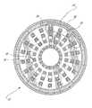
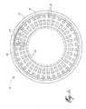
- FIGS. 1 a and 1 bare a schematic cross-sectional views of examples of an electric machine suitable for use with the present invention.
- FIG. 2is a block diagram showing an example of a system for monitoring the temperature of an electric machine.
- FIG. 1 ashows an example of an electric machine 10 of the general type described in applicant's U.S. Pat. No. 6,965,183
- FIG. 1 bshows an example of an electric machine of the general type described in applicant's U.S. Pat. No. 7,262,539, both incorporated herein by reference.
- the machine 10can be used as a motor and/or a generator, and includes a rotor 12 (a permanent magnet rotor is shown in the figures) and a stator 16 having a plurality of primary windings 18 and secondary windings 20 .
- the primary windings 18generate output power in response to rotor rotation (generator) or create a rotating electromagnetic field to cause rotor rotation (motor).
- Primary windings 18 and secondary windings 20are electrically isolated from one another.
- the secondary windings 20are wrapped around a portion of the stator preferably multiple times, such as 25 times in each respective slot, as described in U.S. Pat. No. 7,262,539.
- each slotprovides a sort of coil, the coils are connected in series around the portion of the stator serviced by the secondary winding.
- the secondary windings 20are used to control the operation of the electric machine 10 through affecting primary windings 18 , as described in the incorporated references.
- a rotor magnetic circuit 22 and a secondary magnetic circuit 24are defined in the stator 16 for directing magnetic flux within the machine 10 .
- Secondary windings 20are preferably aluminium, copper or other material (whether pure, alloy or composite, etc.) in which material temperature affects the material's electrical resistivity.
- FIG. 2schematically illustrates an example of a system 30 for monitoring the temperature of one or more secondary windings 20 (three windings connected in series are shown in this example), while machine 10 is in operation without the need for dedicated temperature sensors or thermocouples.
- the system 30comprises a monitoring device 32 connected in series with the windings of interest, in this case secondary windings 20 . If there is more than one set of target windings in the machine 10 , more than one monitoring unit 32 per machine may be provided.
- the secondary windings 20 of machine 10actually comprise a plurality of windings that are connected in series, and are also connected to a voltage source, in this case preferably a variable DC source 25 .
- a voltage sourcein this case preferably a variable DC source 25 .
- input DCmay be provided by source 25 to saturate a portion of the stator 16 to thereby allow regulation of the output current of the primary stator windings 18 over a range of rotor speeds and electrical loads.
- the monitoring device 32is adapted to determine parameters used to determine winding resistivity, such as voltage and current in the secondary windings 20 .
- the parametersare sent to a processor 34 , which may or may not be integrated within the monitoring device 32 , as desired.
- a suitable corrective actioncan be taken, such as to notify a machine operator, to notify a machine controller for automatic machine shutdown or other fault mitigation, and/or to notify a machine maintenance monitoring system for logging an appropriate maintenance action, to name just a few.
- the present system and methodcan be used to monitor the temperature inside the electric machine without a need of dedicated temperature sensors therein.
- the systemcan also be used as an additional monitoring system, if required, when dedicated temperature sensors are provided.
- the present inventionis not limited for use with the machine as shown in FIGS. 1 and 2 , and it may be used with other suitable machine designs as well.
- the type and nature of the windings monitoredmay be any suitable, and the material of which the target windings are made may likewise be any suitable.
- the monitoring of the winding's parametersmay be done in any suitable manner, and any suitable technique may be used to determine the winding's resistance.
- Other changes from the described embodimentmay be apparent to the skilled reader, and are not meant to be excluded from the scope of the appended claims merely because all possible variants and changes have not been exhaustively described.
Landscapes
- Engineering & Computer Science (AREA)
- Power Engineering (AREA)
- Physics & Mathematics (AREA)
- General Physics & Mathematics (AREA)
- Life Sciences & Earth Sciences (AREA)
- Sustainable Development (AREA)
- Sustainable Energy (AREA)
- Transportation (AREA)
- Mechanical Engineering (AREA)
Abstract
Description
The invention relates to temperature monitoring inside electric machines.
In the unlikely event of a turn to turn short-circuit or other electrical fault inside an electric machine such as a motor or generator, the temperature at the faulted winding can become significantly elevated and thereby pose a risk to the continued operation of the machine. However, no other symptoms may be evident initially, until the insulation of the winding deteriorates to a significant level, after which a more serious thermal condition may result. Providing temperature sensors to sense a high temperature within a faulted winding can detect a fault, however, such arrangement adds complexity to the electric machine. Room for improvement exists.
In one aspect, the present invention provides a method for monitoring temperature of at least one winding of an electric machine, the winding having a temperature dependant resistance, the method comprising: determining a resistance of the winding while in operation; and determining a winding temperature of the winding using the resistance therein.
In another aspect, the invention provides a system for monitoring temperature of at least one winding of an electric machine, each winding having an electrical resistance which changes with temperature, the system comprising: a monitor adapted to determine a value indicative of the instantaneous resistance in at least a portion of the at least one winding; and a processor adapted to calculate an instantaneous temperature based on the resistance, and determine the presence of a fault condition based on the temperature.
In a further aspect, there is provided an electric generator system comprising a generator having a permanent magnet rotor and a stator, the stator having at least one output winding connected to a generator load and at least one control winding, the windings disposed in stator slots, the stator defining a first magnetic circuit passing through the stator around a portion of the at least one output winding, the stator defining a second magnetic circuit passing through the stator around another portion of the at least one output winding and a portion of the at least control winding, the first and second magnetic circuits remote from one another, the at least one control winding having an electrical resistance which varies with temperature; a current source connected to the at least one control winding adapted to provide variable DC current thereto, the source and the at least one control winding providing a control circuit; and a fault detection apparatus connected to the control circuit, the fault detection apparatus adapted to determine an electrical resistance of the at least one control winding and detect a fault therefrom.
Reference will now be made to the accompanying figures, in which:
Thesecondary windings 20 ofmachine 10 actually comprise a plurality of windings that are connected in series, and are also connected to a voltage source, in this case preferably avariable DC source 25. For example, as described in the incorporated reference U.S. Pat. No. 7,262,539, input DC may be provided bysource 25 to saturate a portion of thestator 16 to thereby allow regulation of the output current of theprimary stator windings 18 over a range of rotor speeds and electrical loads. Themonitoring device 32 is adapted to determine parameters used to determine winding resistivity, such as voltage and current in thesecondary windings 20.
Once obtained, the parameters are sent to aprocessor 34, which may or may not be integrated within themonitoring device 32, as desired. Theprocessor 34 calculates the instantaneous winding resistance based on the provided parameters. In this case, the voltage and the current data is used to obtain the resistance simply using Ohm's law (i.e. V=IR). Other parameters and other techniques may be used. Whatever the technique used, by monitoring relevant operational parameters of the target winding, such as voltage and current flow through thecontrol windings 20, one can monitor resistance. When the target windings are made of a temperature dependent material, for instance aluminium or copper, the temperature of the windings may be determined from the resistance. This could be done, for instance, using a suitable algorithm in theprocessor 34, or by using a look-up table stored in amemory 36, or in any other suitable manner.
In use, in the event of a short-circuit causing the local temperature in the faulty winding to increase, thereby changing its resistance, the average resistance of the winding or windings will correspondingly increase, and this will be detected by the system. Comparison of a resistance change against a selected threshold will indicate the existence of a fault or other condition requiring attention. Upon detection of a resistance change indicative of a fault condition, a suitable corrective action can be taken, such as to notify a machine operator, to notify a machine controller for automatic machine shutdown or other fault mitigation, and/or to notify a machine maintenance monitoring system for logging an appropriate maintenance action, to name just a few. As well, gradual changes in resistance may be monitored over time for an overall indication of a health trend of the machine, and parameters indicating that a presently operational machine may soon become subject to a fault can be sensed, the fault predicted and an appropriate corrective action taken in advance of any occurrence of the fault.
As can be appreciated, the present system and method can be used to monitor the temperature inside the electric machine without a need of dedicated temperature sensors therein. The system can also be used as an additional monitoring system, if required, when dedicated temperature sensors are provided.
The above description is meant to be exemplary only, and one skilled in the art will recognize that other changes may also be made to the embodiments described without departing from the scope of the invention disclosed as defined by the appended claims. For instance, the present invention is not limited for use with the machine as shown inFIGS. 1 and 2 , and it may be used with other suitable machine designs as well. The type and nature of the windings monitored may be any suitable, and the material of which the target windings are made may likewise be any suitable. The monitoring of the winding's parameters may be done in any suitable manner, and any suitable technique may be used to determine the winding's resistance. Other changes from the described embodiment may be apparent to the skilled reader, and are not meant to be excluded from the scope of the appended claims merely because all possible variants and changes have not been exhaustively described.
Claims (8)
1. A method for monitoring an electric machine comprising a rotor and a stator, the stator having a primary set of stator windings configured to provide an electrical output of the machine and a secondary set of series-connected stator windings electrically isolated from the primary set of stator windings, the secondary set of series-connected stator windings being distributed around at least a portion of the stator and configured to control the electrical output of the primary set of stator windings, the method comprising:
operating the machine by rotating the rotor to generate the electrical output with the primary set of stator windings and providing a DC input current to the secondary set of series-connected stator windings to control the electrical output of the primary set of stator windings;
determining a resistance across the secondary set of series-connected stator windings while the machine is in operation, the resistance determined from the DC current in the secondary set of series-connected stator windings and a DC voltage drop across the secondary set of series-connected stator windings;
estimating a temperature of the secondary set of series-connected stator windings using the resistance determined; and
determining the presence of a machine fault condition by comparing the estimated temperature against a selected threshold condition indicative of a fault.
2. The method ofclaim 1 further comprising the step of taking a corrective action based on a determination that a fault is present.
3. The method ofclaim 1 further comprising using the estimated temperature and the comparison information to determine a suitable corrective action.
4. The method ofclaim 1 , further comprising the step of obtaining trend information over time by storing the estimated temperature over time.
5. The method ofclaim 4 further comprising using the trend information to predict a future maintenance event.
6. The method ofclaim 4 further comprising using the estimated temperature and the comparison information to suggest a possible suitable maintenance action.
7. A system for monitoring an electric machine, the system comprising:
a rotor, a stator, a primary set of stator windings disposed in the stator and configured to conduct electricity induced by rotor rotation, and a plurality of secondary series-connected control windings disposed in the stator and electrically isolated from the primary set of stator windings, the secondary series-connected control windings being configured to permit regulation of said electricity in the primary stator windings upon the application of DC current to the secondary series-connected control windings;
a monitor adapted for monitoring a DC voltage across the secondary series-connected control windings and a DC current across the secondary series-connected control windings; and
a processor adapted to calculate an instantaneous estimated temperature of the secondary series-connected control windings based on the instantaneous DC voltage and DC current, and to determine the presence of a fault condition based on the instantaneous estimated temperature.
8. The method ofclaim 1 wherein the fault is a short circuit in the secondary set of stator windings.
Priority Applications (5)
| Application Number | Priority Date | Filing Date | Title |
|---|---|---|---|
| US11/419,239US8604803B2 (en) | 2006-05-19 | 2006-05-19 | System and method for monitoring temperature inside electric machines |
| PCT/CA2007/000712WO2007134427A1 (en) | 2006-05-19 | 2007-04-26 | System and method for monitoring temperature inside electric machines |
| CA2644038ACA2644038C (en) | 2006-05-19 | 2007-04-26 | System and method for monitoring temperature inside electric machines |
| EP07252053AEP1858131A3 (en) | 2006-05-19 | 2007-05-18 | System and method for monitoring temperature inside electric machines |
| US14/068,546US9614472B2 (en) | 2006-05-19 | 2013-10-31 | System for monitoring temperature inside electric machines |
Applications Claiming Priority (1)
| Application Number | Priority Date | Filing Date | Title |
|---|---|---|---|
| US11/419,239US8604803B2 (en) | 2006-05-19 | 2006-05-19 | System and method for monitoring temperature inside electric machines |
Related Child Applications (1)
| Application Number | Title | Priority Date | Filing Date |
|---|---|---|---|
| US14/068,546DivisionUS9614472B2 (en) | 2006-05-19 | 2013-10-31 | System for monitoring temperature inside electric machines |
Publications (2)
| Publication Number | Publication Date |
|---|---|
| US20070268023A1 US20070268023A1 (en) | 2007-11-22 |
| US8604803B2true US8604803B2 (en) | 2013-12-10 |
Family
ID=38430452
Family Applications (2)
| Application Number | Title | Priority Date | Filing Date |
|---|---|---|---|
| US11/419,239ActiveUS8604803B2 (en) | 2006-05-19 | 2006-05-19 | System and method for monitoring temperature inside electric machines |
| US14/068,546Active2026-10-03US9614472B2 (en) | 2006-05-19 | 2013-10-31 | System for monitoring temperature inside electric machines |
Family Applications After (1)
| Application Number | Title | Priority Date | Filing Date |
|---|---|---|---|
| US14/068,546Active2026-10-03US9614472B2 (en) | 2006-05-19 | 2013-10-31 | System for monitoring temperature inside electric machines |
Country Status (4)
| Country | Link |
|---|---|
| US (2) | US8604803B2 (en) |
| EP (1) | EP1858131A3 (en) |
| CA (1) | CA2644038C (en) |
| WO (1) | WO2007134427A1 (en) |
Cited By (15)
| Publication number | Priority date | Publication date | Assignee | Title |
|---|---|---|---|---|
| WO2015130438A1 (en)* | 2014-02-26 | 2015-09-03 | Schweitzer Engineering Laboratories, Inc. | Power system management |
| US9519301B2 (en) | 2014-02-26 | 2016-12-13 | Schweitzer Engineering Laboratories, Inc. | Contingency-based load shedding |
| US9614472B2 (en) | 2006-05-19 | 2017-04-04 | Pratt & Whitney Canada Corp. | System for monitoring temperature inside electric machines |
| US9954372B2 (en) | 2014-02-26 | 2018-04-24 | Schweitzer Engineering Laboratories, Inc. | Topology determination using graph theory |
| US9981836B2 (en) | 2015-03-31 | 2018-05-29 | Crown Equipment Corporation | Method for controlling a functional system of a materials handling vehicle |
| US10594138B2 (en) | 2016-10-04 | 2020-03-17 | Schweitzer Engineering Laboratories, Inc. | Detection and remediation of transients in electric power systems |
| US10763695B2 (en) | 2016-07-26 | 2020-09-01 | Schweitzer Engineering Laboratories, Inc. | Microgrid power flow monitoring and control |
| US10833507B2 (en) | 2016-11-29 | 2020-11-10 | Schweitzer Engineering Laboratories, Inc. | Island detection and control of a microgrid |
| US10931109B2 (en) | 2019-01-10 | 2021-02-23 | Schweitzer Engineering Laboratories, Inc. | Contingency based load shedding system for both active and reactive power |
| US10992134B2 (en) | 2019-05-10 | 2021-04-27 | Schweitzer Engineering Laboratories, Inc. | Load shedding system for both active and reactive power based on system perturbation |
| US11009931B2 (en) | 2018-07-17 | 2021-05-18 | Schweitzer Engineering Laboratories, Inc. | Voltage assessment prediction system for load/generation shedding |
| US11177657B1 (en) | 2020-09-25 | 2021-11-16 | Schweitzer Engineering Laboratories, Inc. | Universal power flow dynamic simulator |
| US11735913B2 (en) | 2021-05-25 | 2023-08-22 | Schweitzer Engineering Laboratories, Inc. | Autonomous real-time remedial action scheme (RAS) |
| US11929608B2 (en) | 2021-09-01 | 2024-03-12 | Schweitzer Engineering Laboratories, Inc. | Systems and methods for operating an islanded distribution substation using inverter power generation |
| US12218694B2 (en) | 2023-04-05 | 2025-02-04 | Schweitzer Engineering Laboratories, Inc. | Bit pattern sequence compressor |
Families Citing this family (15)
| Publication number | Priority date | Publication date | Assignee | Title |
|---|---|---|---|---|
| US7439713B2 (en) | 2006-09-20 | 2008-10-21 | Pratt & Whitney Canada Corp. | Modulation control of power generation system |
| US8198762B2 (en)* | 2008-01-31 | 2012-06-12 | Pratt & Whitney Canada Corp. | Winding end turn cooling in an electric machine |
| FR2968360B1 (en)* | 2010-12-01 | 2013-01-04 | Continental Automotive France | METHOD FOR DETERMINING THE TEMPERATURE OF AN IGNITION COIL |
| ITMI20111194A1 (en)* | 2011-06-29 | 2012-12-30 | Ansaldo Energia Spa | DEVICE AND METHOD TO PERFORM THERMAL RESISTANCE TESTS ON AT LEAST ONE STATHY BAR OF AN ELECTRIC MACHINE |
| US9014995B2 (en)* | 2012-01-04 | 2015-04-21 | General Electric Company | Collector monitoring system |
| GB201222284D0 (en)* | 2012-12-11 | 2013-01-23 | Nidec Sr Drives Ltd | Estimation of resistance in electrical machines |
| EP2894746B1 (en)* | 2014-01-13 | 2020-02-26 | Siemens Aktiengesellschaft | Method and device for monitoring the temperature of an electric motor |
| DE102014016452B4 (en) | 2014-11-06 | 2019-03-28 | Audi Ag | Method for determining a stator winding temperature of an electrical machine |
| CN104569733B (en)* | 2015-01-09 | 2017-06-06 | 华北电力大学(保定) | A kind of method for determining motor excitation winding interturn short-circuit abort situation |
| US9647602B1 (en)* | 2015-11-04 | 2017-05-09 | GM Global Technology Operations LLC | Determination of stator winding resistance in an electric machine |
| US9932701B2 (en) | 2015-12-29 | 2018-04-03 | Whirlpool Corporation | Laundry appliances using search coils to identify motors and their rotors in order to self-tune control of the motor |
| DE102016106431A1 (en) | 2016-04-08 | 2017-10-12 | Ebm-Papst Mulfingen Gmbh & Co. Kg | temperature monitoring |
| JPWO2018016448A1 (en)* | 2016-07-21 | 2019-07-04 | 日本電産株式会社 | Motor module, motor control device, temperature estimation device, and temperature estimation method |
| CN108781026B (en)* | 2016-12-08 | 2020-10-30 | 深圳市大疆灵眸科技有限公司 | Motor, cradle head, shooting device, aircraft, motor and control method of cradle head |
| DE102021101813A1 (en) | 2021-01-27 | 2022-07-28 | Audi Aktiengesellschaft | Method for checking a model temperature of an electrical machine and motor vehicle determined by means of a temperature model |
Citations (32)
| Publication number | Priority date | Publication date | Assignee | Title |
|---|---|---|---|---|
| US2578455A (en)* | 1949-07-26 | 1951-12-11 | Gen Electric | Circuit for measuring the resistance of energized alternating current apparatus |
| US2912644A (en)* | 1954-11-03 | 1959-11-10 | Smith Corp A O | Resistance and temperature determinations of a motor winding |
| US2922943A (en)* | 1958-06-12 | 1960-01-26 | Carl F Huffman Jr | Electrical machine |
| US3195044A (en)* | 1960-03-29 | 1965-07-13 | Texas Instruments Inc | Resistance-change temperature-measuring apparatus for motor windings and the like |
| US3207980A (en)* | 1960-03-29 | 1965-09-21 | Texas Instruments Inc | Apparatus including an automatic balancing bridge for measuring the temperature of motor windings and the like, including thermaly controlled ballast resistance means |
| US3210657A (en)* | 1960-08-12 | 1965-10-05 | Texas Instruments Inc | Resistance-change temperature sensing apparatus for a.c. motor windings having a.c. and d.c. sources in series |
| US4083001A (en)* | 1976-12-29 | 1978-04-04 | Westinghouse Electric Corporation | Measurement of motor winding temperature |
| US4413325A (en) | 1980-03-26 | 1983-11-01 | El-Fi Innovationer Ab | Methods and apparatuses for determining the temperature of an asynchronous motor |
| US4454465A (en)* | 1981-04-29 | 1984-06-12 | Teledyne Walterboro, A Division Of Teledyne Industries, Inc. | Electric generator that operates with few ampere-turns in field winding |
| CA1191719A (en) | 1982-12-13 | 1985-08-13 | Jack P. Chomicz | Apparatus and method of measuring temperature of energised a.c. windings |
| US4554491A (en)* | 1984-08-10 | 1985-11-19 | Msl Industries, Inc. | Brushless DC motor having a laminated stator with a single stator winding |
| US4899074A (en)* | 1987-10-13 | 1990-02-06 | Magneti Marelli Electrical Limited | Permanent magnet rotary dynamo electric machines |
| JPH0280982A (en)* | 1988-09-19 | 1990-03-22 | Toshiba Corp | Disconnection detection device for synchronous machine field winding |
| US4939437A (en)* | 1988-06-22 | 1990-07-03 | Siemens Energy & Automation, Inc. | Motor controller |
| US5153506A (en)* | 1989-08-22 | 1992-10-06 | Siemens Aktiengesellschaft | Apparatus for measuring a winding temperature of electric machines |
| US5446362A (en) | 1994-06-21 | 1995-08-29 | General Electric Company | Thermal protection for AC traction motors using temperature estimations to calculate torque limits and blower speed requirements |
| EP0726632A1 (en) | 1995-02-10 | 1996-08-14 | The Raymond Corporation | Lift truck with internal temperature monitor and system |
| US6064172A (en)* | 1997-02-11 | 2000-05-16 | Power Superconductor Applications Corporation | Method and apparatus for detection, classification and reduction of internal electrical faults in alternating current propulsion machinery using synchronous detection scheme |
| US6262550B1 (en) | 1999-12-17 | 2001-07-17 | General Electric Company | Electrical motor monitoring system and method |
| US6297742B1 (en)* | 1996-08-22 | 2001-10-02 | Csi Technology, Inc. | Machine monitor with status indicator |
| US6323658B1 (en)* | 1997-10-08 | 2001-11-27 | Reliance Electric Technologies, Llc | Method of conducting broadband impedance response tests to predict stator winding failure |
| WO2002087050A1 (en) | 2001-04-19 | 2002-10-31 | BSH Bosch und Siemens Hausgeräte GmbH | Method and device for measuring the temperature of windings of a drive motor |
| US6496782B1 (en) | 2000-10-30 | 2002-12-17 | General Electric Company | Electric machine monitoring method and system |
| US20030034793A1 (en) | 2001-08-15 | 2003-02-20 | Sang-Bin Lee | Device and method for estimating the resistance of a stator winding for an AC induction motor |
| US20030111976A1 (en)* | 2001-12-13 | 2003-06-19 | Kumar Ajith Kuttannair | Detection of loss of cooling air to traction motors |
| US20040212342A1 (en) | 2001-04-06 | 2004-10-28 | Microchip Technology Incorporated | Battery cover assembly having integrated battery condition monitoring |
| US20040239202A1 (en) | 2003-05-27 | 2004-12-02 | Dooley Kevin Allan | Architecture for electric machine |
| WO2006056040A1 (en) | 2004-11-26 | 2006-06-01 | Pratt & Whitney Canada Corp. | Saturation control of electric machine |
| US7242166B2 (en)* | 2002-07-31 | 2007-07-10 | Sydkraft Ab | Electric machine |
| US7265954B2 (en)* | 2003-10-24 | 2007-09-04 | Daikin Industries, Ltd. | Method for estimating DC motor coil temperature, DC motor control method and their devices |
| US20090051311A1 (en)* | 2007-06-04 | 2009-02-26 | Bin Lu | System and method for determining stator winding resistance in an ac motor |
| US20100194329A1 (en)* | 2009-01-30 | 2010-08-05 | Bin Lu | System and method for determining stator winding resistance in an ac motor using motor drives |
Family Cites Families (4)
| Publication number | Priority date | Publication date | Assignee | Title |
|---|---|---|---|---|
| JPH0687642B2 (en)* | 1986-12-15 | 1994-11-02 | 株式会社日立製作所 | Rotor winding abnormality diagnosis device for rotating electric machine |
| US5510687A (en)* | 1994-04-29 | 1996-04-23 | Allen-Bradley Company, Inc. | Electric motor controller with temperature protection |
| US6118186A (en)* | 1994-09-14 | 2000-09-12 | Coleman Powermate, Inc. | Throttle control for small engines and other applications |
| US8604803B2 (en) | 2006-05-19 | 2013-12-10 | Pratt & Whitney Canada Corp. | System and method for monitoring temperature inside electric machines |
- 2006
- 2006-05-19USUS11/419,239patent/US8604803B2/enactiveActive
- 2007
- 2007-04-26WOPCT/CA2007/000712patent/WO2007134427A1/enactiveApplication Filing
- 2007-04-26CACA2644038Apatent/CA2644038C/ennot_activeExpired - Fee Related
- 2007-05-18EPEP07252053Apatent/EP1858131A3/ennot_activeWithdrawn
- 2013
- 2013-10-31USUS14/068,546patent/US9614472B2/enactiveActive
Patent Citations (36)
| Publication number | Priority date | Publication date | Assignee | Title |
|---|---|---|---|---|
| US2578455A (en)* | 1949-07-26 | 1951-12-11 | Gen Electric | Circuit for measuring the resistance of energized alternating current apparatus |
| US2912644A (en)* | 1954-11-03 | 1959-11-10 | Smith Corp A O | Resistance and temperature determinations of a motor winding |
| US2922943A (en)* | 1958-06-12 | 1960-01-26 | Carl F Huffman Jr | Electrical machine |
| US3195044A (en)* | 1960-03-29 | 1965-07-13 | Texas Instruments Inc | Resistance-change temperature-measuring apparatus for motor windings and the like |
| US3207980A (en)* | 1960-03-29 | 1965-09-21 | Texas Instruments Inc | Apparatus including an automatic balancing bridge for measuring the temperature of motor windings and the like, including thermaly controlled ballast resistance means |
| US3210657A (en)* | 1960-08-12 | 1965-10-05 | Texas Instruments Inc | Resistance-change temperature sensing apparatus for a.c. motor windings having a.c. and d.c. sources in series |
| US4083001A (en)* | 1976-12-29 | 1978-04-04 | Westinghouse Electric Corporation | Measurement of motor winding temperature |
| US4413325A (en) | 1980-03-26 | 1983-11-01 | El-Fi Innovationer Ab | Methods and apparatuses for determining the temperature of an asynchronous motor |
| US4454465A (en)* | 1981-04-29 | 1984-06-12 | Teledyne Walterboro, A Division Of Teledyne Industries, Inc. | Electric generator that operates with few ampere-turns in field winding |
| CA1191719A (en) | 1982-12-13 | 1985-08-13 | Jack P. Chomicz | Apparatus and method of measuring temperature of energised a.c. windings |
| US4554491A (en)* | 1984-08-10 | 1985-11-19 | Msl Industries, Inc. | Brushless DC motor having a laminated stator with a single stator winding |
| US4899074A (en)* | 1987-10-13 | 1990-02-06 | Magneti Marelli Electrical Limited | Permanent magnet rotary dynamo electric machines |
| US4939437A (en)* | 1988-06-22 | 1990-07-03 | Siemens Energy & Automation, Inc. | Motor controller |
| JPH0280982A (en)* | 1988-09-19 | 1990-03-22 | Toshiba Corp | Disconnection detection device for synchronous machine field winding |
| US5153506A (en)* | 1989-08-22 | 1992-10-06 | Siemens Aktiengesellschaft | Apparatus for measuring a winding temperature of electric machines |
| US5446362A (en) | 1994-06-21 | 1995-08-29 | General Electric Company | Thermal protection for AC traction motors using temperature estimations to calculate torque limits and blower speed requirements |
| EP0726632A1 (en) | 1995-02-10 | 1996-08-14 | The Raymond Corporation | Lift truck with internal temperature monitor and system |
| CA2170011C (en) | 1995-02-10 | 2003-09-30 | Paul P. Mccabe | Lift truck with internal temperature monitor and system |
| US6297742B1 (en)* | 1996-08-22 | 2001-10-02 | Csi Technology, Inc. | Machine monitor with status indicator |
| US6064172A (en)* | 1997-02-11 | 2000-05-16 | Power Superconductor Applications Corporation | Method and apparatus for detection, classification and reduction of internal electrical faults in alternating current propulsion machinery using synchronous detection scheme |
| US6323658B1 (en)* | 1997-10-08 | 2001-11-27 | Reliance Electric Technologies, Llc | Method of conducting broadband impedance response tests to predict stator winding failure |
| US6262550B1 (en) | 1999-12-17 | 2001-07-17 | General Electric Company | Electrical motor monitoring system and method |
| US6496782B1 (en) | 2000-10-30 | 2002-12-17 | General Electric Company | Electric machine monitoring method and system |
| US20040212342A1 (en) | 2001-04-06 | 2004-10-28 | Microchip Technology Incorporated | Battery cover assembly having integrated battery condition monitoring |
| US6949945B2 (en)* | 2001-04-19 | 2005-09-27 | BSH Bosch und Siemens Hausgeräte | Method and apparatus for measurement of the winding temperature of a drive motor |
| WO2002087050A1 (en) | 2001-04-19 | 2002-10-31 | BSH Bosch und Siemens Hausgeräte GmbH | Method and device for measuring the temperature of windings of a drive motor |
| US20030034793A1 (en) | 2001-08-15 | 2003-02-20 | Sang-Bin Lee | Device and method for estimating the resistance of a stator winding for an AC induction motor |
| US20030111976A1 (en)* | 2001-12-13 | 2003-06-19 | Kumar Ajith Kuttannair | Detection of loss of cooling air to traction motors |
| US7242166B2 (en)* | 2002-07-31 | 2007-07-10 | Sydkraft Ab | Electric machine |
| US20040239202A1 (en) | 2003-05-27 | 2004-12-02 | Dooley Kevin Allan | Architecture for electric machine |
| US6965183B2 (en) | 2003-05-27 | 2005-11-15 | Pratt & Whitney Canada Corp. | Architecture for electric machine |
| US7265954B2 (en)* | 2003-10-24 | 2007-09-04 | Daikin Industries, Ltd. | Method for estimating DC motor coil temperature, DC motor control method and their devices |
| WO2006056040A1 (en) | 2004-11-26 | 2006-06-01 | Pratt & Whitney Canada Corp. | Saturation control of electric machine |
| US7262539B2 (en)* | 2004-11-26 | 2007-08-28 | Pratt & Whitney Canada Corp. | Saturation control of electric machine |
| US20090051311A1 (en)* | 2007-06-04 | 2009-02-26 | Bin Lu | System and method for determining stator winding resistance in an ac motor |
| US20100194329A1 (en)* | 2009-01-30 | 2010-08-05 | Bin Lu | System and method for determining stator winding resistance in an ac motor using motor drives |
Non-Patent Citations (2)
| Title |
|---|
| EP Search Report, EP07252053; Jun. 24, 2010. |
| International Search Report, PCT/CA2007/000712, Jul. 31, 2007. |
Cited By (16)
| Publication number | Priority date | Publication date | Assignee | Title |
|---|---|---|---|---|
| US9614472B2 (en) | 2006-05-19 | 2017-04-04 | Pratt & Whitney Canada Corp. | System for monitoring temperature inside electric machines |
| US9519301B2 (en) | 2014-02-26 | 2016-12-13 | Schweitzer Engineering Laboratories, Inc. | Contingency-based load shedding |
| US9954372B2 (en) | 2014-02-26 | 2018-04-24 | Schweitzer Engineering Laboratories, Inc. | Topology determination using graph theory |
| WO2015130438A1 (en)* | 2014-02-26 | 2015-09-03 | Schweitzer Engineering Laboratories, Inc. | Power system management |
| US9981836B2 (en) | 2015-03-31 | 2018-05-29 | Crown Equipment Corporation | Method for controlling a functional system of a materials handling vehicle |
| US10763695B2 (en) | 2016-07-26 | 2020-09-01 | Schweitzer Engineering Laboratories, Inc. | Microgrid power flow monitoring and control |
| US10594138B2 (en) | 2016-10-04 | 2020-03-17 | Schweitzer Engineering Laboratories, Inc. | Detection and remediation of transients in electric power systems |
| US10833507B2 (en) | 2016-11-29 | 2020-11-10 | Schweitzer Engineering Laboratories, Inc. | Island detection and control of a microgrid |
| US11009931B2 (en) | 2018-07-17 | 2021-05-18 | Schweitzer Engineering Laboratories, Inc. | Voltage assessment prediction system for load/generation shedding |
| US10931109B2 (en) | 2019-01-10 | 2021-02-23 | Schweitzer Engineering Laboratories, Inc. | Contingency based load shedding system for both active and reactive power |
| US10992134B2 (en) | 2019-05-10 | 2021-04-27 | Schweitzer Engineering Laboratories, Inc. | Load shedding system for both active and reactive power based on system perturbation |
| US11177657B1 (en) | 2020-09-25 | 2021-11-16 | Schweitzer Engineering Laboratories, Inc. | Universal power flow dynamic simulator |
| US11735913B2 (en) | 2021-05-25 | 2023-08-22 | Schweitzer Engineering Laboratories, Inc. | Autonomous real-time remedial action scheme (RAS) |
| US11929608B2 (en) | 2021-09-01 | 2024-03-12 | Schweitzer Engineering Laboratories, Inc. | Systems and methods for operating an islanded distribution substation using inverter power generation |
| US12107414B2 (en) | 2021-09-01 | 2024-10-01 | Schweitzer Engineering Laboratories, Inc. | Systems and methods for operating an islanded distribution substation using inverter power generation |
| US12218694B2 (en) | 2023-04-05 | 2025-02-04 | Schweitzer Engineering Laboratories, Inc. | Bit pattern sequence compressor |
Also Published As
| Publication number | Publication date |
|---|---|
| US20070268023A1 (en) | 2007-11-22 |
| EP1858131A3 (en) | 2010-07-28 |
| US20140055103A1 (en) | 2014-02-27 |
| CA2644038A1 (en) | 2007-11-29 |
| EP1858131A2 (en) | 2007-11-21 |
| CA2644038C (en) | 2017-07-18 |
| US9614472B2 (en) | 2017-04-04 |
| WO2007134427A1 (en) | 2007-11-29 |
Similar Documents
| Publication | Publication Date | Title |
|---|---|---|
| US8604803B2 (en) | System and method for monitoring temperature inside electric machines | |
| EP2372882B1 (en) | Stator coil coolant flow reduction monitoring | |
| Yun et al. | Detection and classification of stator turn faults and high-resistance electrical connections for induction machines | |
| US9459320B2 (en) | Fault detection in brushless exciters | |
| JP5543981B2 (en) | Robust online stator winding fault identification system | |
| EP2867985B1 (en) | System for measuring soft starter current and method of making same | |
| CN104332954B (en) | For carrying out Thermal protection and the circuit of power regulation to motor | |
| Lee et al. | A remote and sensorless thermal protection scheme for small line-connected ac machines | |
| US11320489B2 (en) | Field winding interlayer short-circuit detection apparatus and field winding interlayer short-circuit detection method | |
| GB2481101A (en) | Detecting a diode fault in a brushless generator exciter | |
| MX2013007921A (en) | System and method for monitoring current drawn by a protected load in a self-powered electronic protection device. | |
| US20150364976A1 (en) | Overheat detection device for electric motor equipped with multiple ptc thermistors | |
| EP3271933B1 (en) | Electronic trip units powered by current transformers and circuit breakers comprising the same | |
| JP5406513B2 (en) | Circuit breaker with automatic breaker rating setting | |
| JP4733989B2 (en) | Kenting monitoring control system and operation method thereof | |
| US8248739B2 (en) | Electrical switching apparatus and protection apparatus determining thermal age of another apparatus or a number of insulators | |
| JP2014196920A (en) | Leak detection device | |
| Zocholl | AC motor protection | |
| US7420343B2 (en) | Current limiting DC motor starter circuit | |
| KR101348543B1 (en) | Apparatus and method for detecting winding fault of permanent magnet motor | |
| US9912214B2 (en) | Wire-wound stator having phases with difference in temperature-responsive electrical resistance | |
| US20060097597A1 (en) | Method for monitoring electrical insulation on a rotor of an electrical machine | |
| Kanase et al. | Condition Monitoring and Controlling of Induction Motors based on PIC Microcontroller and GSM System | |
| EP3084799B1 (en) | Electrical switching apparatus including alternating current electronic trip circuit with arc fault detection circuit | |
| Ray | Development of relaying system for induction motor protection |
Legal Events
| Date | Code | Title | Description |
|---|---|---|---|
| AS | Assignment | Owner name:PRATT & WHITNEY CANADA CORP., CANADA Free format text:ASSIGNMENT OF ASSIGNORS INTEREST;ASSIGNOR:DOOLEY, KEVIN ALLAN;REEL/FRAME:017642/0694 Effective date:20060518 | |
| STCF | Information on status: patent grant | Free format text:PATENTED CASE | |
| FPAY | Fee payment | Year of fee payment:4 | |
| MAFP | Maintenance fee payment | Free format text:PAYMENT OF MAINTENANCE FEE, 8TH YEAR, LARGE ENTITY (ORIGINAL EVENT CODE: M1552); ENTITY STATUS OF PATENT OWNER: LARGE ENTITY Year of fee payment:8 | |
| MAFP | Maintenance fee payment | Free format text:PAYMENT OF MAINTENANCE FEE, 12TH YEAR, LARGE ENTITY (ORIGINAL EVENT CODE: M1553); ENTITY STATUS OF PATENT OWNER: LARGE ENTITY Year of fee payment:12 |