US8604723B2 - Interlaced multi-energy radiation sources - Google Patents
Interlaced multi-energy radiation sourcesDownload PDFInfo
- Publication number
- US8604723B2 US8604723B2US13/476,477US201213476477AUS8604723B2US 8604723 B2US8604723 B2US 8604723B2US 201213476477 AUS201213476477 AUS 201213476477AUS 8604723 B2US8604723 B2US 8604723B2
- Authority
- US
- United States
- Prior art keywords
- accelerator
- energy
- frequency
- magnetron
- power pulses
- Prior art date
- Legal status (The legal status is an assumption and is not a legal conclusion. Google has not performed a legal analysis and makes no representation as to the accuracy of the status listed.)
- Active
Links
Images


Classifications
- H—ELECTRICITY
- H05—ELECTRIC TECHNIQUES NOT OTHERWISE PROVIDED FOR
- H05H—PLASMA TECHNIQUE; PRODUCTION OF ACCELERATED ELECTRICALLY-CHARGED PARTICLES OR OF NEUTRONS; PRODUCTION OR ACCELERATION OF NEUTRAL MOLECULAR OR ATOMIC BEAMS
- H05H7/00—Details of devices of the types covered by groups H05H9/00, H05H11/00, H05H13/00
- H05H7/02—Circuits or systems for supplying or feeding radio-frequency energy
- H—ELECTRICITY
- H05—ELECTRIC TECHNIQUES NOT OTHERWISE PROVIDED FOR
- H05H—PLASMA TECHNIQUE; PRODUCTION OF ACCELERATED ELECTRICALLY-CHARGED PARTICLES OR OF NEUTRONS; PRODUCTION OR ACCELERATION OF NEUTRAL MOLECULAR OR ATOMIC BEAMS
- H05H9/00—Linear accelerators
- H—ELECTRICITY
- H05—ELECTRIC TECHNIQUES NOT OTHERWISE PROVIDED FOR
- H05H—PLASMA TECHNIQUE; PRODUCTION OF ACCELERATED ELECTRICALLY-CHARGED PARTICLES OR OF NEUTRONS; PRODUCTION OR ACCELERATION OF NEUTRAL MOLECULAR OR ATOMIC BEAMS
- H05H9/00—Linear accelerators
- H05H9/04—Standing-wave linear accelerators
- H05H9/048—Lepton LINACS
- H—ELECTRICITY
- H01—ELECTRIC ELEMENTS
- H01J—ELECTRIC DISCHARGE TUBES OR DISCHARGE LAMPS
- H01J2235/00—X-ray tubes
- H01J2235/08—Targets (anodes) and X-ray converters
- H—ELECTRICITY
- H05—ELECTRIC TECHNIQUES NOT OTHERWISE PROVIDED FOR
- H05H—PLASMA TECHNIQUE; PRODUCTION OF ACCELERATED ELECTRICALLY-CHARGED PARTICLES OR OF NEUTRONS; PRODUCTION OR ACCELERATION OF NEUTRAL MOLECULAR OR ATOMIC BEAMS
- H05H7/00—Details of devices of the types covered by groups H05H9/00, H05H11/00, H05H13/00
- H05H7/02—Circuits or systems for supplying or feeding radio-frequency energy
- H05H2007/022—Pulsed systems
- H—ELECTRICITY
- H05—ELECTRIC TECHNIQUES NOT OTHERWISE PROVIDED FOR
- H05H—PLASMA TECHNIQUE; PRODUCTION OF ACCELERATED ELECTRICALLY-CHARGED PARTICLES OR OF NEUTRONS; PRODUCTION OR ACCELERATION OF NEUTRAL MOLECULAR OR ATOMIC BEAMS
- H05H7/00—Details of devices of the types covered by groups H05H9/00, H05H11/00, H05H13/00
- H05H7/02—Circuits or systems for supplying or feeding radio-frequency energy
- H05H2007/025—Radiofrequency systems
Definitions
- This inventionrelates generally to radiation sources, and more specifically, to interlaced multiple energy radiation sources.
- Radiationis commonly used in the non-invasive inspection of contents of objects, such as luggage, bags, briefcases, cargo containers, and the like, to identify hidden contraband at airports, seaports, and public buildings, for example.
- the contrabandmay include hidden guns, knives, explosive devices, illegal drugs, and Special Nuclear Material, such as uranium and plutonium, for example.
- One common inspection systemis a line scanner, where the object to be inspected is passed through a fan beam or pencil beam of radiation emitted by a source of X-ray radiation. Radiation transmitted through the object is attenuated to varying degrees by the contents of the object and detected by a detector array. Attenuation is a function of the type and amount (thickness) of the materials through which the radiation beam passes. Radiographic images of the contents of the object may be generated for inspection, showing the shape, size and varying amounts of the contents. In some cases the material type may be deduced.
- Standard cargo containersare typically 20-50 feet long (6.1-15.2 meters), 8 feet high (2.4 meters), and 6-9 feet wide (1.8-2.7 meters).
- Larger air cargo containerswhich are used to contain a plurality of pieces of luggage or other cargo to be stored in the body of an airplane, may be up to about 240 ⁇ 118 ⁇ 96 inches (6.1 ⁇ 3.0 ⁇ 2.4 meters).
- MeV radiation sourcesare typically required to generate radiation with sufficient energy to penetrate through standard cargo containers and the larger air cargo containers.
- MeV radiation sourcestypically comprise a particle accelerator, such as a linear radiofrequency (“RF”) particle accelerator, to accelerate charged particles, and a source of charged particles, such as an electron gun, to inject charged particles into the accelerator.
- the linear acceleratormay comprise a series of linearly arranged, electromagnetically coupled resonant cavities in which standing or traveling electromagnetic waves for accelerating the charged particles are supported.
- the charged particles injected into the resonant cavitiesare accelerated up to a desired energy and directed toward a conversion target to produce radiation.
- the accelerated charged particlesare electrons and the target is a heavy material, such as tungsten, Bremsstrahlung or X-ray radiation is generated. Electrons accelerated to a nominal energy of 6 MeV and impacting tungsten, will cause generation of X-ray radiation having an energy of 6 MV, for example.
- a microwave (RF) power sourceprovides RF power to the cavities of the accelerator.
- the microwave sourcemay be an oscillating microwave power tube, such as a magnetron, or an amplifying microwave power tube, such as a klystron.
- the microwave sourcesare powered by modulators, which generate high electric power pulses having peak electric powers of from 1 MW to 10 MW, and average powers of from 1 kW to 40 kW, for example.
- Characteristics of the modulator outputmay be varied to vary the output of the microwave power source. For example, the amplitude of the high-voltage pulses driving the oscillator or the amplifier may be varied to change the microwave power output. Alternatively, in an amplifier, the microwave input signal may be varied to change the microwave power output.
- the acceleratorwhich may have a loaded Q value of 5000, for example, is very sensitive to the frequency of the input RF power. Maximum acceptance of microwave power provided by the RF source is achieved when the center frequency of the microwave power matches the accelerator resonance frequency. Otherwise, some or most of the microwave power provided to the accelerator will be reflected, preventing acceleration of the charged particles to the desired beam energy.
- the RF frequencymay be adjusted to match the accelerator resonance frequency by a mechanical or electrical tuner.
- the RF power provided to the acceleratorcauses heating and expansion of the accelerator structure, which causes a slow frequency drift of the accelerator resonance frequency. Such drift is most noticeable in the first minute or two of operation, but may continue due to environment conditions.
- An automatic frequency controller(“AFC”) is generally required to servo the RF source frequency to track the accelerator resonance frequency, as is known in the art.
- the AFCsamples and compares microwave signals provided to the accelerator with those reflected from the accelerator, to determine the required tuning of the microwave source.
- An AFCis generally sufficient to match the frequency of the RF source to the resonance frequency of the accelerator, during steady state operation.
- An example of an AFCis described in U.S. Pat. No. 3,820,035, which is incorporated by reference herein.
- pulse to pulse frequency jitter in the magnetronmay also cause a small mismatch between the frequency of a magnetron and the resonance frequency of the accelerator. Such mismatch varies from pulse to pulse and adds some noise to the system. This may be improved by feeding some microwave power reflected from the accelerator back into the magnetron by a reflector and variable phase shifter, for example, as described in U.S. Pat. No. 3,714,592, which is also incorporated by reference herein.
- the reflector/variable phase shiftermay be referred to as a “phase wand.”
- the information that may be derived about the material type of the contents of objects by X-ray scanningmay be enhanced by the use of radiation beams in the MV energy range, with two or more different energy spectra that interact differently with the material contents of the object. For example, the attenuation of a 6 MV X-ray radiation beam by the contents of the object will be different from the attenuation a 9 MV X-ray radiation beam by the same contents, due to the differing effects of Compton Scattering and induced pair production on the different energy beams.
- a ratio of the attenuations at the two X-ray energiesmay be indicative of the atomic numbers of the material through which the radiation beam passes, as described in U.S. Pat. No. 5,524,133, for example. More sophisticated dual energy analysis techniques are described in U.S. Pat. No. 7,257,188, for example, which is assigned to the assignee of the present invention and incorporated by reference herein. Ratios of high and low energy attenuations may also be plotted against object thickness to facilitate material identification, as described in “Dual Energy X-ray radiography for automatic high-Z material detection,” G. Chen et al, NIM (B), Volume 261 (2007), pp. 356-359.
- a single acceleratormay accelerate beams of electrons or other charged particles to different energies by being excited at two different RF power levels by the RF power generator. It may be necessary to rapidly switch the power generator between generation of two power levels. Switching on the order of a millisecond may be desirable, for example.
- the frequency of the RF power pulses, as well as the resonance frequency of the acceleratormay also change pulse to pulse. Improved techniques for matching the frequency of the RF power pulses generated by the RF power generator to the resonance frequency of the accelerator on a pulse to pulse basis would be advantageous.
- Embodiments of the inventionprovide improved frequency control in klystron, and mechanically and electrically tuned magnetron based dual or multi-energy systems.
- a method of operating an acceleratorcomprising generating first radiofrequency power pulses having first powers and first frequencies, generating second radiofrequency power pulses having second powers and second frequencies different than the first powers and first frequencies, and providing the first and second radiofrequency power pulses to resonant cavities of a single accelerator in a predetermined sequence.
- the methodfurther comprises matching the first frequency of the first radiofrequency power pulses to a first resonance frequency of the accelerator while providing the first radiofrequency power pulses to the accelerator, and matching the second frequency of the second radiofrequency power pulses to a second resonance frequency of the accelerator different from the first resonance frequency while providing the second radiofrequency power pulses to the accelerator.
- a method of generating radiation at multiple energiescomprising sequentially providing first electric power and second electric power to a microwave power generator.
- the second electric poweris different from the first electric power.
- First radiofrequency power pulses having a first power at a first frequency and second radiofrequency power pulses having a second power different than the first power and a second frequency different than the first frequency, based at least in part, on the first and second electric powers,are sequentially generated by the power generator.
- the first and second radiofrequency power pulsesare sequentially provided to resonant cavities of a single particle accelerator.
- the methodfurther comprises matching the first frequency of the first radiofrequency power pulses to a first resonance frequency of the accelerator while providing the first radiofrequency power pulses to the accelerator, and matching the second frequency of the second radiofrequency power pulses to a second resonance frequency of the accelerator different from the first resonance frequency while providing the second radiofrequency power pulses to the accelerator.
- Charged particlesare injected into the resonant cavities of the accelerator, and are sequentially accelerated by the accelerator to a first energy at a first resonance frequency of the accelerator and to a second energy at a second resonance frequency of the accelerator different from the first resonance frequency based, at least in part, on the first and second radiofrequency power pulses.
- the first and second accelerated charged particlesare sequentially collided with a target to generate radiation having first and second respective energies.
- a multi-energy radiation sourcecomprising an accelerator to accelerate charged particles, a charged particle source coupled to the accelerator to provide charged particles to the accelerator, and a target downstream of the accelerator. Impact of the accelerated charged particles on the target causes generation of radiation.
- the sourcefurther comprises a power generator coupled to the accelerator to selectively provide first and second radiofrequency power pulses to the accelerator. The second radiofrequency power pulses have a different power and frequency than the first radiofrequency power pulses.
- the sourcefurther comprises first means for matching a first frequency of the power generator to a first resonance frequency of the accelerator while the first radiofrequency power pulses are provided to the accelerator, and second means for matching a second frequency of the power generator to a second resonance frequency of the accelerator while the second radiofrequency power pulses are provided to the accelerator.
- Impact of the first charged particles on the targetcauses generation of radiation at a first energy and impact of the second charged particles on the target causes generation of radiation at a second energy different from the first energy.
- a method of generating radiation at multiple energies and dosescomprising sequentially providing first electric power and second electric power to a microwave power generator, the second electric power being different from the first electric power, sequentially generating by the power generator first radiofrequency power pulses having a first power and second radiofrequency power pulses having a second power different than the first power, based at least in part, on the first and second electric powers, and sequentially providing the first and second radiofrequency power pulses to resonant cavities of a single particle accelerator.
- the methodfurther comprises sequentially driving a charged particle source at a third electric power and a fourth electric power different from the first electric power, injecting first and second currents of charged particles into the resonant cavities of the accelerator, wherein the first and second currents are based, at least in part, on the third and fourth electric powers, respectively, and sequentially accelerating by the accelerator the injected charged particles to a first energy and to a second energy different from the first energy based, at least in part, on the first and second radiofrequency power pulses
- the first and second currents of accelerated charged particlesare collided with a target to generate radiation having first and second different energies and first and second, different, respective dose rates.
- an AFCis used to adjust the magnetron frequency, at one power level.
- the magnetron tuningmay be adjusted by the AFC so that the frequency of high RF power pulses generated by the magnetron matches the accelerator resonance frequency when high RF power pulses are provided to the accelerator.
- the magnetronis operated at conditions under which it undergoes a frequency shift that at least partially matches the resonance frequency shift of the accelerator while the low RF power pulses are provided to the accelerator.
- the conditionsmay include the amplitude of the voltage of the electric power pulses provided to the magnetron from the modulator.
- the conditionsmay further include maintaining the magnetic field of the magnetron constant.
- a phase wandmay further match the magnetron frequency to the resonance frequency, if needed, for both the high and low energy pulses.
- the AFCmay be used during the low energy pulses and the magnetron may be operated under conditions that the magnetron frequency shift matches the accelerator resonance frequency shift during the high RF power pulses, instead.
- two independent AFC controlsmay be used to determine the reference voltages for magnetron or RF driver frequency control for the high RF power pulses and the low RF power pulses, respectively. Those voltages are then used to control the magnetron or RF driver frequency on a pulse by pulse basis.
- different electron beam currentsmay be provided for different energy beam pulses to achieve desired dose output for each energy pulse, by controlling the particle source, such as an electron gun, on a pulse by pulse basis.
- the particle sourcesuch as an electron gun
- the particle sourcesuch as an electron gun
- either the voltage pulse amplitude or timing with relative to microwave pulsecan be varied.
- grid voltagecan also be varied on pulse by pulse basis.
- FIG. 1is a schematic diagram of an example of multi-energy radiation source in accordance with an embodiment of the invention
- FIG. 2is a graph of an example of PFN voltage provided to a magnetron versus magnetron frequency (MHz);
- FIG. 3is an example of the waveforms and signal timing for the radiation source of FIG. 1 ;
- FIG. 4is another example of a multi-energy radiation source in accordance with the embodiment of FIG. 1 , including a solid state modulator (“SSM”);
- SSMsolid state modulator
- FIG. 5is a schematic diagram of another example of a multi-energy radiation source, in accordance with an embodiment of the invention, in which a klystron is used to drive an accelerator;
- FIG. 6is an example of waveforms and signal timing for the multi-energy radiation source of FIG. 5 ;
- FIG. 7is another example of waveforms and signal timing for the multi-energy radiation source of FIG. 5 ;
- FIG. 8is another example of a multi-energy radiation source in accordance with an embodiment of the invention, which includes an electrically tunable magnetron.
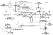
- FIG. 1is a schematic diagram of an example of multi-energy radiation source 100 in accordance with an embodiment of the invention.
- the radiation source 100is configured to accelerate charged particles, such as electrons, to first and second nominal energies in an interlaced manner, and collide the accelerated charged particles with a target to generate radiation having two different energy spectra, one having a high energy, and another having a low energy, in an interlaced manner.
- the first nominal electron energyis 6 MeV, which causes generation of a 6 MV radiation beam (high energy in this example)
- the second nominal energyis 3.5 MeV, which causes generation of a 3.5 MV radiation beam (low energy in this example)
- ppspulse rate of 200 or 300 pulses per second
- energiesmay be generated, such as 9 MV and 6 MV, at lower or higher pulse rates.
- the pulse ratemay be 400 pps, for example.
- More than two radiation energiesmay be generated, such as 6 MV, 9 MV, and 15 MV, for example, in any desired sequence.
- the radiation source 100comprises a guide or accelerator 102 , a charged particle source 104 coupled to the accelerator, and a target 106 coupled to the accelerator by a drift tube 108 , for example.
- Charged particles provided to the accelerator 102 by the charged particle source 104are accelerated by the accelerator up to a desired energy and directed toward the target 106 .
- Impact of the accelerated charged particles with the targetcauses generation of radiation.
- the charged particlesmay be electrons and the charged particle source 104 may be an electron gun, such as a diode or triode electron gun, for example.
- the target 106may comprise tungsten, for example. In the case of accelerated electrons impacting a heavy target material such as tungsten, the impact causes the generation of X-ray radiation, as is known in the art.
- the accelerator 102may comprise a plurality of electromagnetically coupled resonant cavities (not shown), configured such that different electromagnetic field strengths in the cavities cause electrons to be accelerated to different nominal energies, such as 6 MeV and 3.5 MeV in this example, as is known in the art. Impact of electrons accelerated to different nominal energies on the target causes generation of X-ray radiation beams having different energies, such as 6 MV and 3.5 MV, respectively, in this example, as is known in the art.
- the accelerator 102may be an electron linear accelerator comprising a plurality of axially aligned electromagnetically coupled resonant cavities (not shown), as is known in the art.
- the linear acceleratormay be an S-band or X-band standing wave linear accelerator, for example.
- a suitable acceleratoris an M6A series S-band linear accelerator used in the Linatron® MTM Series X-ray sources, available from Varian Medical Systems, Inc., Palo Alto, Calif., which has a nominal resonance frequency of about 2998 MHz.
- the M6A linear acceleratoris configured to generate X-ray radiation beams having nominal energies of 6 MV and 3.5 MV.
- the loaded Q of the accelerator 102may be 5000, for example.
- a traveling wave linear acceleratorcould be used, instead.
- the accelerator 102is powered by microwave power, also referred to as RF power in the art, which is provided by a magnetron 110 .
- the frequency band of the magnetron 110is selected to match the frequency band of the accelerator 102 .
- the magnetron 110is configured or selected to generate RF power in the S-band, as well.
- a magnet 111is positioned adjacent to the magnetron 110 to provide the required magnetic field to the magnetron, as is known in the art.
- the magnet 111may have a magnetic field strength of 1500 Gauss, for example.
- the magnet 111may be a permanent magnet or an electromagnet.
- the magnet 111is an electromagnet that provides an adjustable magnetic field, which is kept constant during operation.
- the RF power generated by the magnetron 110is provided to the resonant cavities within the accelerator 102 in the form of individual pulses of RF power, per cycle.
- Each pulse of RF powercomprises a large number of RF micropulses.
- the frequency of the micropulsesis set in this example by mechanical tuning of the magnetron 110 , and other factors described below.
- the RF powerestablishes electromagnetic standing waves within the resonant cavities. The standing waves accelerate the electrons (or other such charged particles) provided into the cavities by the electron gun 104 , resulting in electron beams comprising electrons accelerated to nominal energies up to the designed maximum acceleration energy of the accelerator for the provided RF power.
- the magnetron 110generates RF power at approximately 2.6 MW and 1.5 MW, resulting in nominal accelerated electron energies of 6 MeV and 3.5 MeV, respectively, and generation of 6 MV and 3.5 MV X-ray radiation beams, respectively.
- the magnetron 110is capable of switching between the RF powers at a rate of 200 pulses per second (“pps”) or 300 pps, for example.
- the magnetron 110 in this examplemay be an MG5193-Alphatron mechanically tunable S-band magnetron, available from e2v Technologies Inc., Elmsford, N.Y. (“e2v”), for example.
- the magnetron 110can be tuned over a frequency range of 2993 MHz to 3002 MHz, has a peak output power of up to 2.6 MW, and is water cooled.
- the frequency rangeis said to be achieved by turning its mechanical tuner by 4.75 revolutions.
- the maximum allowed peak anode voltageis said to be 48 kV.
- the maximum allowed peak anode currentis said to be 110 Amperes.
- the maximum average input electric poweris said to be 6.0 KW.
- the pulse durationis said to be around 5.0 microseconds ( ⁇ s).
- a circulator 112such as a 3-port circulator, is provided between the magnetron 110 and the accelerator 102 to isolate the magnetron from the accelerator 102 by directing RF power reflected from the accelerator away from the magnetron, toward a water load 114 coupled to the circulator, for example.
- the water load 114absorbs the reflected RF power.
- Some of the RF power directed toward the water loadis reflected back to the circulator 112 , which directs that RF power toward the magnetron 110 , by a phase wand 116 , as is known in the art. This helps to stabilize the magnetron 110 , reducing pulse to pulse frequency jitter in the magnetron 110 by pulling the frequency of the magnetron to the frequency of the accelerator 102 .
- the phase wand 116may be a reflector/variable phase shifter provided between the circulator 112 and the water load 114 .
- An example of a reflector/variable phase shifteris described above and in U.S. Pat. No. 3,714,592, which is incorporated by reference herein. Such frequency pulling is effective over a narrow frequency range, such as up to about 100 kHz.
- the magnetron 110is driven by a modulator 117 comprising an electric power source, such as a high voltage power supply (“HVPS”) 118 , a pulse forming network (“PFN”) 120 , and a thyratron 124 .
- the HVPS 118charges the PFN 120 for every pulse.
- the output of the PFN 120may be provided to an optional transformer (“XFMR”) 122 .
- the thyratron 124is connected to one end of the PFN 120 and the transformer 122 is connected to the other end.
- a high control voltage (Control V 1 ) 126 and a low control voltage (Control V 2 ) 128are provided by voltage supplies (not shown) to an analog switch 130 between the control voltages and the HVPS 118 .
- the analog switch 130is configured to switch between the Control V 1 and the Control V 2 at the desired switching rate between the generation of X-ray radiation beams having a higher and a lower nominal energy, such as 200 pulses per second (“pps”) or 300 pps, for example.
- the analog switch 130may be controlled by a logic signal from a controller 132 programmed to cause switching at the desired rate and the desired time within each cycle.
- the selected control voltageis provided to the HVPS 118 , which charges the PFN 120 to the corresponding higher or lower voltage, dependent on the control voltage received.
- the Control V 1is set to 8.8 volts and the Control V 2 may be set to 6.4 volts, to set the high voltage to 22 kV and the low voltage to 16 kV, respectively.
- Other voltage settingsmay be selected.
- the controller 132may comprise simple logic control circuitry or a processor, such as a microprocessor, for example.
- the controller 132After the PFN 120 has been charged by the HVPS 118 to the appropriate level and at a time required by X-ray imaging, the controller 132 , or another controller, causes the thyratron 124 to conduct, releasing electric power stored in PFN 120 to the transformer 122 .
- the output of the HVPS 118is also shorted to ground.
- the HVPS 118is designed to initiate self-protection when shorted, as is known in the art.
- the transformer 122multiplies the voltage of the pulse to the level required by the magnetron 110 .
- the transformer 122also drives the electron gun 104 , saving the cost and complexity of providing an additional power source.
- the electron gunmay be a diode gun, for example.
- a tap switcher 134 between the electron gun 104 and the transformer 122switches between taps on the transformer 122 to connect a desired voltage to the electron gun.
- the voltage provided to the electron gun 104determines the electron beam current provided by the electron gun to the accelerator 102 , which affects the dose rate of the generated radiation. It may be desirable to deliver the different radiation beams at different dose rates.
- the tap switcher 134may switch between taps at the same rate as the analog switch 130 switches between the control voltages 126 , 128 . The dose rates may thereby be changed on a pulse by pulse basis, if desired.
- the tap switcher 134may be controlled by the controller 132 or by another controller.
- Part of the voltage provided by the HVPS 118goes to the electric load, in this case the transformer 122 and the magnetron 110 connected to the secondary side of the transformer.
- 11 kVgoes to the load and of the 16 kV
- 10 kVgoes to the load.
- the transformer 122raises the 11 kV and 10 kV to 44 kV and 40 kV respectively, for example, which is provided to the magnetron 110 .
- the magnetic fieldis kept constant while the different RF power pulses are generated, resulting in different impedences in the magnetron 110 , as is known in the art.
- the transformer 122also drives the electron gun 104 by another secondary winding.
- the transformer 122is optional.
- the HVPS 118 and/or the PFN 120may be configured to generate the higher voltages.
- the transformer 122may have multiple outputs or taps for gun voltage.
- there are nine (9) taps on the transformerproviding nominal voltages of 1.4, 2.1, 2.8, 4.4, 6.0, 7.6, 9.0, 10.6, and 12 kV at a PFN voltage of 25 kV, for example.
- Two of the nine tapsare connected to the input of side of tap switcher 134 , based on the electron currents required to generate the desired dose rates of the high and low energy radiation beams in a particular application.
- the two tapsmay be manually selected and connected to inputs of the tap switcher 134 .
- the transformermay be obtained from Stangenes Industries, Palo Alto, Calif., for example.
- the tap switcher 134which may be a solid state tap switcher that switches at a rate of 200 pps or 300 pps in the present example, may also be obtained from Stangenes Industries of Palo Alto, Calif., for example.
- a separate power source 123may be provided to drive the electron gun 104 , instead of the transformer 122 , to vary the power on a pulse by pulse basis.
- the timing of gun voltage pulsemay be adjusted relative to the RF pulse, adding additional flexibility to the control of the dose output.
- a triode gunmay be used instead of using a diode gun. In case of a triode gun, the grid voltage and timing can be adjusted, adding further flexibility to dose output control.
- the power source 123if provided, may be controlled by the controller 132 or other such controller, as well.
- the accelerator 102is a resonant structure whose RF power acceptance is sensitive to RF frequency. The better the match between the frequency of the RF power pulses and the accelerator resonance frequency, the better the acceptance. If the match is not sufficient, the accepted RF power into the accelerator 102 may not be sufficient to adequately excite electromagnetic fields inside the accelerator cavities to accelerate the electrons to the desired energies, as is known in the art.
- RF power provided to the accelerator 102may heat the accelerator components, causing expansion that may shift the resonance frequency.
- Other factors that may cause the resonance frequency to varyinclude vibrations of the accelerator 102 .
- the RF output frequency of the magnetron 110must therefore be changed to match the resonance frequency, to ensure that sufficient RF power will be accepted by the accelerator 102 .
- the resonance frequency of the accelerator 102shifts on a pulse by pulse basis in response to differential heating of the accelerator by the differing RF powers sequentially provided by the magnetron 110 .
- the accelerator temperatureis higher after the high power RF pulse than after the low power RF pulse, causing differential expansion of the components of the accelerator 102 , from pulse to pulse.
- differential expansionchanges the resonance frequency of the accelerator 102 when the following RF pulse arrives.
- the resonance frequencyhas been found to shift by about 200 kHz, such as from about 2998 MHz to about 2998.2 MHz and back to about 2998 MHz, for example, from each high to low to high pulse of RF power.
- An automatic frequency controller (“AFC”) 136samples RF power pulses that go to (FWD) and are reflected from (REF) the accelerator 102 , at a location between the circulator 112 and the accelerator 102 , to detect the frequency matching condition and adjust magnetron frequency tuner if necessary to match the resonant frequency of the accelerator.
- the FWD RF signalmay be sampled between the magnetron 110 and the circulator 112 instead, and REF RF signal can be sampled between the circulator 112 and the load 114 instead.
- the sampling timesmay be controlled by the controller 132 or other such controller, for example.
- the AFC 136may be based on a quadrupole hybrid module and an adjustable phase shifter, which are commercially available. AFCs of this type are described in U.S. Pat. No. 3,820,035, which is incorporated by reference herein, for example.
- a microwave circuitaccepts a reflected (“REF”) signal, and a forward (“FWD”) signal, and generates vector sums of the two signals with various relative phase shifts. The amplitude of those vector sums are measured and the need to adjust RF source frequency is determined by electronic circuitry or software.
- the output signal of the AFC 136may be employed in a feedback loop to the mechanical tuner (not shown) of the magnetron 110 . Over multiple cycles, the magnetron frequency approaches the resonance frequency of the accelerator.
- the mechanical tuning of the magnetron 110is not fast enough to respond to automatic frequency control for every pulse of RF power.
- Automatic frequency control of a mechanically tunable magnetron 110may not be sufficient at slower pulse rates, either. Therefore, in accordance with this embodiment of the invention, the mechanical tuner of the magnetron 110 is only set by the AFC 136 to a position to match the frequency of only one type of RF power pulse, in this example the high RF power pulse.
- the different voltages provided to the magnetron 110cause different charge densities within the magnetron, causing a frequency shift known as “frequency pushing” in the art.
- the different voltagesalso differentially heat the magnetron 110 , which may also cause frequency shifts. It has been found that with proper selection of the amplitudes of the voltage pulses provided to the magnetron 110 , particularly when operated at constant magnetic field from pulse to pulse, the frequency shift in the magnetron 110 will be in the same direction and of nearly the same or the same quantity (about 200 KHz in this example), as the resonance frequency shift in the accelerator 102 . Remaining frequency mismatch up to about 100 KHz may be matched by the action of the phase wand 116 , which further adjusts the magnetron frequency toward the accelerator resonance frequency.
- FIG. 2is a graph of PFN voltage provided to the magnetron 110 by the PFN 120 versus magnetron frequency (MHz) for voltages ranging from 13 kV to 22 kV, and frequencies of 2992.0-2999.0 MHz, at a constant magnetic field of 1450 Gauss.
- This datawas collected with the same magnetron model described above, which was not connected to the resonant load of an accelerator at the time.
- the magnetron tunerwas fixed at a position to generate 2998 MHz RF power pulses at about 22 kV PFN voltage.
- the PFN voltages selected to drive the magnetronbe as far apart as feasible, for a particular accelerator.
- the magnetron frequencyis tuned to 2998.0 MHz, which is near to the nominal resonance frequency of the accelerator 102 .
- the magnetron frequencyincreases up to about 200 KHz at 16.5 kV.
- the magnetron frequencyfalls from about 2998.2 MHz to about 2996.5 MHz. The magnetron frequency then rises and falls again as the PFN voltage decreases from 14.5 kV to 13 kV.
- the resonance frequencyincreases by about 200 KHz in this example from the high RF power pulse to the low RF power pulse. Since the frequency shift in the magnetron in the voltage range of from 16.5 kV to 20 kV also increases frequency, selection of the second, low RF power pulse voltage in this range enables at least partial matching of the frequency of the magnetron 110 to the frequency of the accelerator during the low RF power pulses. Further matching would be provided by the effect of the phase wand 116 . The frequency increase of about 200 KHz at 16.5 kV provides a close match to the resonance frequency shift, which may be further improved by the effect of the phase wand 116 . In combination with the automatic frequency control of the high RF power pulse in this example, good frequency matching is provided pulse to pulse. It is noted that automatic frequency control may be used to match the low RF power pulse frequency to the accelerator resonance frequency and magnetron frequency shift and the phase wand 116 may be used to match the high RF power pulse frequency to the accelerator resonance frequency, instead.
- FIG. 3is an example of the waveforms and signal timing for the radiation source 100 of FIG. 1 .
- Row Ashows the voltage waveform provided by the analog switch 130 to the HVPS 118 .
- Row Bshows the voltage waveform provided by the tap switcher 134 to the electron gun 104 .
- Row Cshows the voltage waveform across the PFN 120 .
- Row Dshows the high and low power RF pulses emitted by the magnetron 110 .
- Row Eshows the timing of AFC 136 sampling of the FWD and REW signals.
- Each pulsing cyclestarts when the HVPS 118 has recovered from the prior pulse.
- the HVPS 118starts to charge the PFN 120 , at a rate determined by HVPS current and PFN load to a peak voltage determined by the Control V 1 126 , such as 22 kV, for example.
- the PFN 120has been charged to the peak voltage. The voltage is held at that level until at a time T 1 b , when the thyratron 124 conducts and causes electric power stored in the PFN 120 to be released to the magnetron 110 and the gun 104 through the transformer 122 in the form of a pulse.
- the magnetron 110Upon receipt of the electric power from the PFN 120 at about the time T 1 b , the magnetron 110 generates RF power and provides it to the accelerator 102 , and electrons are injected from the gun 104 to the accelerator 102 . Injected electrons are accelerated by the standing electromagnetic waves in the resonant cavities of the accelerator 102 to a nominal energy of 6 MeV in this example, exit the accelerator, and impact the target 106 , causing generation of X-ray radiation having an energy of 6 MV, at a first dose rate, also at about the time T 1 b.
- the HVPS 118senses that its output is shorted to the ground and initiates self protection, blocking charging of the PFN 120 from the time T 1 b to a time T 2 .
- the thyratron 124also recovers to a non-conducting status after PFN discharge.
- the HVPS 118is ready to charge the next pulse.
- the analog switch 130flips the control voltage to the HVPS 118 from Control V 1 126 to Control V 2 128 .
- the tap switcher 134flips from connecting the tap 1 to the gun 104 to connecting the tap 2 to the gun 104 .
- the HVPS 118then charges the PFN 120 to the second peak voltage determined by the Control V 2 128 , such as 16 kV, for example.
- the PFN 120has been charged to the peak voltage.
- the time period from T 2 to T 2 amay be different than the time period from T 1 to T 1 a because the PFN 120 is charged to a different voltage.
- the voltageis held at the peak voltage until a time T 2 b , when the thyratron 124 again conducts and causes electric power stored in the PFN 120 to be released to the magnetron 110 and the gun 104 through the transformer 122 .
- the magnetron 110generates RF power and provides it to the accelerator 102 , and electrons are injected from the gun 104 to the accelerator.
- the RF power generated by the magnetron 110 and the electron current injected from the gun 104 to the accelerator 102 at the time T 2 bare different from the generated RF power and emitted electron current at the time T 1 b in the previous pulse, in this example.
- Injected electronsare accelerated by the accelerator 102 to a nominal energy of 3.5 MeV in this example, exit the accelerator, and impact the target 106 , causing generation of X-ray radiation having an energy of 3.5 MV, at a second dose rate different from the first dose rate, also at about the time T 2 b.
- the HVPS 118senses that its output is shorted to the ground, initiates self protection, and blocks PFN charging. The thyratron 124 also recovers to non-conducting status after PFN discharge. After the blocking period ends at the time T 3 , the HVPS 118 is ready to charge the next pulse, to cause generation of a high RF power pulse and resulting generation of another high energy radiation beam.
- the analog switch 130flips the control voltage from the Control V 2 128 to the Control V 1 126 .
- the tap switcher 134flips to connect the tap 1 to the gun 104 , to provide the voltage associated with the tap 1 into the gun. The pulse cycles are repeated to generate high and low power RF pulses, and high and lower energy radiation beams having different dose rates, if desired, in an interlaced manner.
- the analog switch 130 and the gun tap switch 134do not have to switch at exactly the times T 1 , T 2 , etc. Switching may be programmed to happen sooner, but not before the PFN 120 has fully discharged the previous pulse. Switching may also be programmed to happen later, but not after the HVPS 118 has charged the PFN 120 to the desired voltage.
- the charging time periods for the high power pulse T 1 -T 1 a , T 3 -T 3 a . . . of the PFN 120are about 1.5 milliseconds, and the charging time periods for the low power pulses T 2 -T 2 a , T 4 -T 4 a . . . are about 1.1 milliseconds, for example.
- the charging time and the hold time for each high voltage pulse T 1 -T 1 b , T 3 -T 3 b . . .are about 3.2 milliseconds.
- the HVPS 118 blocking recovery periods T 1 b -T 2 , T 2 b -T 3 , T 3 b -T 4are each about 100 microseconds.
- the alternating sequencemay comprise two high RF power pulses followed by two low RF power pulses, or one high RF power pulse followed by two low RF power pulses, etc., resulting in corresponding alternating sequences of high and low energy radiation beams.
- FIG. 4is another example of a multi-energy radiation source 200 in which a solid state modulator (“SSM”) 202 is used instead of the modulator 117 defined by the HVPS 118 , PFN 120 , and thyratron 124 in FIG. 1 , to drive the magnetron 110 at the desired voltage levels.
- SSMsolid state modulator
- the controller 132is not shown to simplify illustration. In this example, no transformer is provided, although that is an option.
- the SSM 202may include a digital switch or a separate switch may be provided (not shown).
- the controller 132(not shown), or one or more other such controllers, may control operation of the SSM 102 , as well as the other components of the system 200 , as described above.
- the SSM 202would deliver pulsed electric power (a series of high and low voltage pulses) at times T 1 b , T 2 b , etc., corresponding to the output of the PFN 120 , shown in Row C of FIG. 3 .
- the remainder of the components of the source 200 and their operationmay be the same as in FIG. 1 .
- the particle source 104such as an electron gun, may be driven by a separate electric power source.
- FIG. 5is a schematic diagram of another example of a multi-energy radiation source 300 , in which a klystron 301 is used to drive an accelerator 302 , instead of the magnetron 110 , shown in FIGS. 1 and 3 .
- the source 300also comprises a charged particle source 304 , such as an electron gun, a target 306 , a circulator 308 , and an RF load 310 , such as water, as in the example of FIG. 1 . No phase wand is needed in this example.
- a controllersuch as the controller 132 shown in the system 100 of FIG. 1 , is not shown to simplify illustration.
- An RF driver 316is also coupled to the klystron 312 to provide low level RF power to the klystron 301 , such as 100 W, for example.
- the output of the RF driver 316may be controlled by an input voltage provided by a voltage source 318 , as known in the art.
- a modulator 320is also coupled to the klystron 301 , to provide pulses of electric power to the klystron.
- a gun driver 322is coupled to the gun 304 to provide the required voltage pulses to the gun.
- the klystron 301amplifies the low level RF power to a higher power to excite the accelerator 302 .
- the klystron 301may amplify the input power of 100 W to about 5 MW.
- the output RF power of the klystron 301may be varied on a pulse by pulse basis to vary the excitation RF power provided to the accelerator 302 by either varying the output power of the RF driver 316 , or by varying the electric power provided to the klystron by the modulator 320 (as in the magnetron example of FIGS. 1 and 3 , for example).
- the electric power pulses provided to the klystron 301 by the modulator 320would have the same amplitude.
- the low level RF power pulses from the RF driver 316may be 60 W and 100 W, and the corresponding high level RF power from the klystron 301 may be 3 MW and 5 MW, for example.
- the electric power pulses provided by the modulator 320would vary between two different amplitudes.
- RF driver output frequencyis typically controlled by a reference voltage, as known in the art.
- two automatic frequency controllers (“AFC”) 324 , 326are used to track the two accelerator resonance frequencies for high power pulses and low power pulses, respectively.
- Each AFC 324 , 326samples the RF power provided in a forward direction (FWD) to the accelerator 302 and the RF power reflected (REF) from the accelerator, from a location between the circulator 306 and the accelerator.
- FWD RF signals for AFCs 324 , 326may be sampled between the klystron 301 and the circulator 308
- REF RF signalmay be sampled between the circulator 308 and the load 310 .
- the reference voltages from the two AFCsmay be provided to the RF driver 316 to adjust its frequency in interlaced manner, with high power pulse AFC 324 in effect during generation of high power RF pulses and low power pulse AFC 326 in effect during generation of low RF power pulses.
- the high power pulse AFC 324determines the reference voltage that should be sent to the RF driver so that high power pulses match the resonance frequency of the accelerator 302 while high power pulses are provided to the accelerator
- the low power pulse AFC 326determines the reference voltage that should be sent to the RF driver so that low power pulses match the resonance frequency of the accelerator while low power pulses are provided.
- An AFC switch 328switches between the high pulse AFC 324 and the low pulse AFC 326 , to selectively provide the feedback to the RF driver 316 .
- the AFC switch 328switches between an input node 1 and an input node 2 to connect the frequency control reference voltage input of the RF driver 316 to the high pulse AFC 324 output and the low pulse AFC 326 output, respectively, under the control of a controller, such as the controllers discussed above.
- the AFC switch 328may be controlled by a controller (not shown) to switch at the desired rate and at the desired times, such as the controller discussed above. Operation of other components of the system may be controlled by the controller or other such controllers, as well.
- FIG. 6shows the timing and waveforms for one example of the X-ray source 300 of FIG. 5 .
- Row Ashows the operation of the AFC switch 328 .
- Row Bshows the RF power control voltage from the voltage source 218 to the RF driver 316 .
- Row Cshows the low level RF pulses provided by the RF driver 316 to the klystron 301 .
- Row Dshows the pulsed electric power provided by the modulator 320 , which can be a PFN or SSM, to the klystron 312 .
- Row Eshows the high level RF pulses provided by the klystron 312 to the accelerator 302 .
- the low level RF signals provided to the klystron 312alternate between a high pulse and a low pulse, in Row C.
- the AFC switch 328switches between the high and low pulse AFCs 324 , 326 .
- the low level RF signalsare provided, constant pulses of electric power are provided by the modulator 314 to the klystron 301 .
- Alternating high and low RF power pulsesare thereby generated and output by the klystron 301 to the accelerator 302 , in coordination with alternating levels of voltage pulses provided by the gun driver 322 to the gun 304 (not shown in FIG. 6 ) to provide different electron currents to the accelerator.
- high and low energy radiation beams at different energies and at different dose rates, if desired,are thereby generated, in an interlaced manner. Different alternating patterns of high/low RF pulses, and high/low energy radiation beams may be provided.
- FIG. 7shows an alternative drive scheme for the X-ray source 300 of FIG. 5 , in which the RF power control voltage is constant in Row B, the low level RF pulses provided by the RF driver 316 to the klystron 301 are constant in Row C, the pulsed electric power provided by the modulator 314 to the klystron 301 varies between a high and low voltage in Row D, and corresponding high and low RF power pulses are generated and output by the klystron 301 in Row E.
- the AFC switching shown in Row A in FIG. 7is the same in FIG. 6 and is not repeated.
- the AFC switch 328switches between the high and low pulse AFCs 324 , 326 in between the high and low power pulses provided by the modulator 314 to the klystron 301 shown in Row D.
- high and low energy radiation beams at different energies and different dose rates, if desired,are thereby generated, in an interlaced manner.
- Different alternating patterns of high/low RF pulses, and high/low energy radiation beamsmay be provided, as above.
- FIG. 8is an example of a multi-energy radiation source in accordance with an embodiment of the invention, wherein the accelerator 102 is driven by an electrically tuned magnetron 110 a . All the elements shown in FIG. 1 are provided in this example, as well, and are commonly numbered.
- the controller 132 of FIG. 1is not shown in FIG. 8 to simplify illustration but it should be understood that such a controller, or other such controller or controllers, are provided in this example, as well, to control operation of the components.
- a low pulse AFC 138is also provided, to detect the low RF power pulses reflected from the accelerator 102 .
- the high pulse AFC 136 and the low pulse AFC 138provide control voltages to an AFC switch 140 .
- the switch 140switches between providing the appropriate reference voltage from each AFC 136 , 138 to the electrically tunable magnetron, to adjust the frequency of the magnetron when the high and low RF power pulses are generated, respectively.
- the AFC switch 140is controlled by the controller 132 (not shown in FIG. 8 ) or other such controller, to switch at the appropriate times.
- the high pulse AFC 136 and the low pulse AFC 138are also controlled by the controller 132 to sample the reflected RF power at the appropriate times, as discussed above with respect to the klystron based system of FIG. 5 .
- the phase wand 116also assists in matching the magnetron frequencies with the accelerator resonance frequencies for the high and low RF power pulses. Alternating high and low RF power pulses are generated and output by the magnetron 110 a to the accelerator 102 , in coordination with alternating levels of voltage pulses provided by the tap switcher 134 to the gun 104 to provide different electron currents to the accelerator. As above, high and low energy radiation beams are thereby generated, at different dose rates, if desired, in an interlaced manner. Different alternating patterns of high/low RF pulses, and high/low energy radiation beams may be provided, as above.
- the system of FIG. 1could be configured to generate radiation beams at three or more energies, by providing three or more, different control voltages to the HVPS 118 .
- the AFC 136may be configured to actively adjust the frequency of RF power pulses at one of those RF power levels while the magnetron 110 may be operated to undergo frequency shifts while generating the other RF power pulses that match the resonance frequency shifts of the accelerator 102 .
- Driving voltagesmay be selected for the two other power levels, as described above with respect to the low power RF pulses, for example.
- the phase wand 116would also assist in matching the magnetron frequencies to the accelerator resonance frequencies.
- the gun 104may also be provided with additional voltages for each different radiation beam energy, if desired, to vary the dose rate.
- the energy pulsesmay be generated in any desired sequence to cause generation of radiation beams of differing energies, in the desired pattern.
- an additional AFCcould be provided to adjust the frequency for power pulses for each additional power level.
- the AFC switch 328 , 140would be configured or controlled to feed the reference voltages into the RF driver 316 or the magnetron 110 a in synchronization with the output RF power level, in the desired pattern.
Landscapes
- Physics & Mathematics (AREA)
- Engineering & Computer Science (AREA)
- Plasma & Fusion (AREA)
- Spectroscopy & Molecular Physics (AREA)
- Particle Accelerators (AREA)
Abstract
Description
Claims (25)
Priority Applications (1)
| Application Number | Priority Date | Filing Date | Title |
|---|---|---|---|
| US13/476,477US8604723B2 (en) | 2008-08-12 | 2012-05-21 | Interlaced multi-energy radiation sources |
Applications Claiming Priority (2)
| Application Number | Priority Date | Filing Date | Title |
|---|---|---|---|
| US12/228,350US8183801B2 (en) | 2008-08-12 | 2008-08-12 | Interlaced multi-energy radiation sources |
| US13/476,477US8604723B2 (en) | 2008-08-12 | 2012-05-21 | Interlaced multi-energy radiation sources |
Related Parent Applications (1)
| Application Number | Title | Priority Date | Filing Date |
|---|---|---|---|
| US12/228,350ContinuationUS8183801B2 (en) | 2008-08-12 | 2008-08-12 | Interlaced multi-energy radiation sources |
Publications (2)
| Publication Number | Publication Date |
|---|---|
| US20120230471A1 US20120230471A1 (en) | 2012-09-13 |
| US8604723B2true US8604723B2 (en) | 2013-12-10 |
Family
ID=41669527
Family Applications (2)
| Application Number | Title | Priority Date | Filing Date |
|---|---|---|---|
| US12/228,350Active2030-08-04US8183801B2 (en) | 2008-08-12 | 2008-08-12 | Interlaced multi-energy radiation sources |
| US13/476,477ActiveUS8604723B2 (en) | 2008-08-12 | 2012-05-21 | Interlaced multi-energy radiation sources |
Family Applications Before (1)
| Application Number | Title | Priority Date | Filing Date |
|---|---|---|---|
| US12/228,350Active2030-08-04US8183801B2 (en) | 2008-08-12 | 2008-08-12 | Interlaced multi-energy radiation sources |
Country Status (6)
| Country | Link |
|---|---|
| US (2) | US8183801B2 (en) |
| EP (1) | EP2319281B1 (en) |
| JP (1) | JP5599398B2 (en) |
| CN (1) | CN102160469B (en) |
| RU (1) | RU2508617C2 (en) |
| WO (1) | WO2010019228A2 (en) |
Cited By (4)
| Publication number | Priority date | Publication date | Assignee | Title |
|---|---|---|---|---|
| US9867271B2 (en) | 2014-05-16 | 2018-01-09 | American Science And Engineering, Inc. | Source for intra-pulse multi-energy X-ray cargo inspection |
| US10600609B2 (en) | 2017-01-31 | 2020-03-24 | Rapiscan Systems, Inc. | High-power X-ray sources and methods of operation |
| US11266006B2 (en)* | 2014-05-16 | 2022-03-01 | American Science And Engineering, Inc. | Method and system for timing the injections of electron beams in a multi-energy x-ray cargo inspection system |
| US11865370B2 (en) | 2020-01-02 | 2024-01-09 | Shanghai United Imaging Healthcare Co., Ltd. | Systems and methods for controlling radiation output |
Families Citing this family (55)
| Publication number | Priority date | Publication date | Assignee | Title |
|---|---|---|---|---|
| US7915840B1 (en)* | 2007-04-24 | 2011-03-29 | The United States Of America As Represented By The United States Department Of Energy | RF power recovery feedback circulator |
| US8183801B2 (en) | 2008-08-12 | 2012-05-22 | Varian Medical Systems, Inc. | Interlaced multi-energy radiation sources |
| US8330397B2 (en)* | 2008-09-16 | 2012-12-11 | Varian Medical Systems, Inc. | Device for reducing peak field an accelerator system |
| US8198587B2 (en) | 2008-11-24 | 2012-06-12 | Varian Medical Systems, Inc. | Compact, interleaved radiation sources |
| US8232748B2 (en) | 2009-01-26 | 2012-07-31 | Accuray, Inc. | Traveling wave linear accelerator comprising a frequency controller for interleaved multi-energy operation |
| US8203289B2 (en) | 2009-07-08 | 2012-06-19 | Accuray, Inc. | Interleaving multi-energy x-ray energy operation of a standing wave linear accelerator using electronic switches |
| US8311187B2 (en)* | 2010-01-29 | 2012-11-13 | Accuray, Inc. | Magnetron powered linear accelerator for interleaved multi-energy operation |
| US8284898B2 (en)* | 2010-03-05 | 2012-10-09 | Accuray, Inc. | Interleaving multi-energy X-ray energy operation of a standing wave linear accelerator |
| GB2481602B (en) | 2010-06-30 | 2017-11-15 | E2V Tech (Uk) Ltd | Switching arrangement |
| RU2452143C2 (en)* | 2010-07-05 | 2012-05-27 | Демидова Елена Викторовна | Method of generating deceleration radiation with pulse-by-pulse energy switching and radiation source for realising said method |
| DE102010032214A1 (en)* | 2010-07-26 | 2012-01-26 | Siemens Aktiengesellschaft | Method and arrangement for controlling sound and shock waves in a target of a particle accelerator |
| US8472583B2 (en) | 2010-09-29 | 2013-06-25 | Varian Medical Systems, Inc. | Radiation scanning of objects for contraband |
| US9258876B2 (en) | 2010-10-01 | 2016-02-09 | Accuray, Inc. | Traveling wave linear accelerator based x-ray source using pulse width to modulate pulse-to-pulse dosage |
| US8836250B2 (en) | 2010-10-01 | 2014-09-16 | Accuray Incorporated | Systems and methods for cargo scanning and radiotherapy using a traveling wave linear accelerator based x-ray source using current to modulate pulse-to-pulse dosage |
| US8942351B2 (en) | 2010-10-01 | 2015-01-27 | Accuray Incorporated | Systems and methods for cargo scanning and radiotherapy using a traveling wave linear accelerator based X-ray source using pulse width to modulate pulse-to-pulse dosage |
| US9167681B2 (en) | 2010-10-01 | 2015-10-20 | Accuray, Inc. | Traveling wave linear accelerator based x-ray source using current to modulate pulse-to-pulse dosage |
| DE102010042148A1 (en)* | 2010-10-07 | 2012-04-12 | Siemens Aktiengesellschaft | Method for exciting a vibration in a resonator |
| US8803453B2 (en) | 2011-06-22 | 2014-08-12 | Varian Medical Systems, Inc. | Accelerator system stabilization for charged particle acceleration and radiation beam generation |
| JP2013026070A (en)* | 2011-07-22 | 2013-02-04 | Mitsubishi Heavy Ind Ltd | X-ray generator, and control method of x-ray generator |
| CN102612251B (en)* | 2012-03-13 | 2015-03-04 | 苏州爱因智能设备有限公司 | Double-microwave-source electronic linear accelerator |
| US9246495B2 (en) | 2012-03-21 | 2016-01-26 | Siemens Aktiengesellschaft | Resonator arrangement and method for exciting a resonator |
| DE102012209185B4 (en)* | 2012-05-31 | 2019-05-29 | Siemens Healthcare Gmbh | High frequency source for a linear accelerator |
| US20140002196A1 (en)* | 2012-06-25 | 2014-01-02 | Paul H. Leek | Method and system for controlling the frequency of a high power microwave source |
| DE102012212720A1 (en)* | 2012-07-19 | 2014-01-23 | Siemens Aktiengesellschaft | MeV electron source e.g. electron gun, for use in e.g. computer tomography-like machine, has linear accelerator supplying high frequency power that is selected in milli-second region and/or electron flow selected in region by drive unit |
| US8878432B2 (en) | 2012-08-20 | 2014-11-04 | Varian Medical Systems, Inc. | On board diagnosis of RF spectra in accelerators |
| US9119281B2 (en) | 2012-12-03 | 2015-08-25 | Varian Medical Systems, Inc. | Charged particle accelerator systems including beam dose and energy compensation and methods therefor |
| CN103019213A (en)* | 2012-12-19 | 2013-04-03 | 江苏安德信超导加速器科技有限公司 | Adjusting control system and adjusting and control method for continuous variable-energy irradiation accelerator |
| US9008278B2 (en)* | 2012-12-28 | 2015-04-14 | General Electric Company | Multilayer X-ray source target with high thermal conductivity |
| US9326366B2 (en) | 2013-03-14 | 2016-04-26 | The Board Of Trustees Of The Leland Stanford Junior University | Intra pulse multi-energy method and apparatus based on RF linac and X-ray source |
| US9778391B2 (en)* | 2013-03-15 | 2017-10-03 | Varex Imaging Corporation | Systems and methods for multi-view imaging and tomography |
| EP2804451B1 (en)* | 2013-05-17 | 2016-01-06 | Ion Beam Applications S.A. | Electron accelerator having a coaxial cavity |
| CN104470193B (en) | 2013-09-22 | 2017-07-25 | 同方威视技术股份有限公司 | Method and system for controlling a standing wave accelerator |
| US9086496B2 (en) | 2013-11-15 | 2015-07-21 | Varian Medical Systems, Inc. | Feedback modulated radiation scanning systems and methods for reduced radiological footprint |
| KR101449610B1 (en) | 2013-12-09 | 2014-10-13 | 한국원자력연구원 | RF Automatic Frequency Control Module and the Control Method for a stable operation and high power of the radio frequency electron accelerator |
| US11589449B2 (en)* | 2014-02-27 | 2023-02-21 | ETM Electromatic, Inc. | Scanning linear accelerator system having stable pulsing at multiple energies and doses |
| US9661734B2 (en)* | 2014-02-27 | 2017-05-23 | ETM Electromatic, Inc. | Linear accelerator system with stable interleaved and intermittent pulsing |
| US9622333B2 (en)* | 2014-02-27 | 2017-04-11 | Etm Electromatic, Inc | Linear accelerator system with stable interleaved and intermittent pulsing |
| KR101588690B1 (en)* | 2014-12-11 | 2016-01-28 | 한국원자력연구원 | Frequency control apparatus and method for magnetron in rf electron accelerator |
| RU2610712C9 (en)* | 2015-09-30 | 2017-04-27 | Общество с ограниченной ответственностью "Лаборатория электронных ускорителей МГУ" | Method for generation of deceleration radiation with pulse-by-pulse energy switching and radiation source for implementation thereof |
| KR101773881B1 (en)* | 2016-02-26 | 2017-09-04 | 성균관대학교 산학협력단 | RF signal apparatus for 3 pole elcectron gun |
| CN107153367B (en)* | 2016-09-28 | 2020-09-18 | 医科达(北京)医疗器械有限公司 | Method and apparatus for controlling output frequency of radio frequency source |
| DE102016222373A1 (en) | 2016-11-15 | 2018-05-17 | Siemens Healthcare Gmbh | Method for operating a linear accelerator and linear accelerator |
| CN106979016B (en)* | 2017-05-26 | 2019-02-05 | 东北大学 | A microwave pre-split hard rock tunnel boring machine cutter head |
| CN107580404B (en)* | 2017-08-30 | 2020-03-17 | 上海联影医疗科技有限公司 | Control method for linear accelerator and linear accelerator |
| CN109599316B (en)* | 2017-09-30 | 2020-09-08 | 中国人民解放军国防科技大学 | An X-band High Gain and High Efficiency Triaxial Relativistic Klystron Amplifier |
| CN108235556B (en)* | 2017-12-29 | 2020-03-10 | 上海联影医疗科技有限公司 | Microwave device, control method thereof and linear accelerator |
| EP3785496A1 (en)* | 2018-04-25 | 2021-03-03 | A.D.A.M. Sa | A proton linear accelerator system for irradiating tissue with two or more rf sources |
| US10693464B2 (en)* | 2018-05-18 | 2020-06-23 | Varex Imaging Corporation | Configurable linear accelerator |
| GB2582343B (en)* | 2019-03-20 | 2023-11-22 | Elekta ltd | Magnetron for a radiotherepy device |
| KR102188804B1 (en)* | 2019-09-25 | 2020-12-09 | 포항공과대학교 산학협력단 | Calibration Method for High Voltage Measurements in Klystron |
| DE102020214128B4 (en)* | 2020-11-10 | 2022-06-02 | Siemens Healthcare Gmbh | Rules of an X-ray pulse chain generated by a linear accelerator system |
| CN113597082B (en)* | 2021-08-12 | 2022-04-08 | 中国原子能科学研究院 | A standing wave accelerating tube and radiation equipment |
| CN114051309B (en)* | 2021-11-03 | 2024-08-06 | 北京航天广通科技有限公司分公司 | System and method for controlling radio frequency power and amplitude of particle accelerator |
| CN116390326A (en)* | 2023-03-28 | 2023-07-04 | 北京机械工业自动化研究所有限公司 | An X-band lightweight accelerator main control box |
| CN116399458B (en)* | 2023-03-29 | 2025-09-09 | 中国科学院西安光学精密机械研究所 | Ultra-high time resolution photoelectric detector and application method thereof |
Citations (54)
| Publication number | Priority date | Publication date | Assignee | Title |
|---|---|---|---|---|
| US2817821A (en) | 1954-09-17 | 1957-12-24 | Raytheon Mfg Co | Grid magnetron frequency pushing controls |
| US3714592A (en) | 1971-12-06 | 1973-01-30 | Varian Associates | Network for pulling a microwave generator to the frequency of its resonant load |
| US3806836A (en) | 1972-01-10 | 1974-04-23 | R Alsmeyer | Simplified floating deck pulse modulator |
| US3820035A (en) | 1973-02-26 | 1974-06-25 | Varian Associates | Microwave automatic frequency control circuit |
| US3965434A (en) | 1972-12-01 | 1976-06-22 | Shm Nuclear Corporation | Automatic frequency control system for driving a linear accelerator |
| US4988919A (en) | 1985-05-13 | 1991-01-29 | Varian Associates, Inc. | Small-diameter standing-wave linear accelerator structure |
| US5044006A (en) | 1990-04-27 | 1991-08-27 | Cyrulnik Reuven A | Microwave frequency modulation of x-ray beam for radio therapy treatment system |
| EP0673187A1 (en) | 1994-03-17 | 1995-09-20 | Hitachi, Ltd. | A particle beam accelerator, and a method of operation therefor |
| US5471516A (en) | 1994-10-06 | 1995-11-28 | Varian Associates, Inc. | Radiotherapy apparatus equipped with low dose localizing and portal imaging X-ray source |
| US5524133A (en) | 1992-01-15 | 1996-06-04 | Cambridge Imaging Limited | Material identification using x-rays |
| US5608403A (en) | 1995-01-31 | 1997-03-04 | The Titan Corporation | Modulated radiation pulse concept for impairing electrical circuitry |
| US5661377A (en) | 1995-02-17 | 1997-08-26 | Intraop Medical, Inc. | Microwave power control apparatus for linear accelerator using hybrid junctions |
| US5661774A (en) | 1996-06-27 | 1997-08-26 | Analogic Corporation | Dual energy power supply |
| US5841237A (en)* | 1997-07-14 | 1998-11-24 | Lockheed Martin Energy Research Corporation | Production of large resonant plasma volumes in microwave electron cyclotron resonance ion sources |
| SU762754A1 (en) | 1977-03-23 | 1999-02-27 | Московский Инженерно-Физический Институт | Device for high-frequency power supply of resonance accelerating section |
| US5933335A (en) | 1996-08-28 | 1999-08-03 | Siemens Medical Systems, Inc. | Compact solid state klystron power supply |
| GB2335487A (en) | 1998-03-19 | 1999-09-22 | Heimann Systems Gmbh & Co | X-ray image processing |
| US6038284A (en) | 1998-01-15 | 2000-03-14 | Siemens Medical Systems, Inc. | Precision dosimetry in an intensity modulated radiation treatment system |
| US6069936A (en) | 1997-08-18 | 2000-05-30 | Eg&G Astrophysics | Material discrimination using single-energy x-ray imaging system |
| WO2000043760A2 (en) | 1999-01-20 | 2000-07-27 | Heimann Systems (Societe Anonyme) | System for differentiating between organic and inorganic substances |
| US6151381A (en) | 1998-01-28 | 2000-11-21 | American Science And Engineering, Inc. | Gated transmission and scatter detection for x-ray imaging |
| US6301326B2 (en) | 1998-11-02 | 2001-10-09 | Perkinelmer Detection Systems, Inc. | Sheet detection system |
| US6327339B1 (en) | 1999-03-25 | 2001-12-04 | Kie Hyung Chung | Industrial x-ray/electron beam source using an electron accelerator |
| US6366021B1 (en) | 2000-01-06 | 2002-04-02 | Varian Medical Systems, Inc. | Standing wave particle beam accelerator with switchable beam energy |
| US6407505B1 (en) | 2001-02-01 | 2002-06-18 | Siemens Medical Solutions Usa, Inc. | Variable energy linear accelerator |
| US20020094059A1 (en) | 2000-02-10 | 2002-07-18 | Lee Grodzins | System and Method for inspecting an object using spatially and spectrally distinguished beams |
| US6483163B2 (en) | 1997-09-02 | 2002-11-19 | Nikon Corporation | Photoelectric conversion devices and photoelectric conversion apparatus employing the same |
| US6493424B2 (en) | 2001-03-05 | 2002-12-10 | Siemens Medical Solutions Usa, Inc. | Multi-mode operation of a standing wave linear accelerator |
| US20020186577A1 (en)* | 2001-06-06 | 2002-12-12 | Siemens Medical Systems, Inc. | Unified power architecture |
| WO2004030162A2 (en) | 2002-09-27 | 2004-04-08 | Scantech Holdings, Llc | System for alternately pulsing energy of accelerated electrons bombarding a conversion target |
| US6824653B2 (en) | 2003-02-21 | 2004-11-30 | Agilent Technologies, Inc | Magnetron with controlled DC power |
| US6844689B1 (en) | 2003-08-29 | 2005-01-18 | Mevex Corporation | Multiple beam linear accelerator system |
| US6856105B2 (en) | 2003-03-24 | 2005-02-15 | Siemens Medical Solutions Usa, Inc. | Multi-energy particle accelerator |
| CN1599537A (en) | 2003-08-22 | 2005-03-23 | 美国西门子医疗解决公司 | Electronic energy switch for particle accelerator |
| US20050117683A1 (en) | 2000-02-10 | 2005-06-02 | Andrey Mishin | Multiple energy x-ray source for security applications |
| US7110500B2 (en) | 2003-09-12 | 2006-09-19 | Leek Paul H | Multiple energy x-ray source and inspection apparatus employing same |
| US7140771B2 (en) | 2003-09-22 | 2006-11-28 | Leek Paul H | X-ray producing device with reduced shielding |
| US7162005B2 (en) | 2002-07-19 | 2007-01-09 | Varian Medical Systems Technologies, Inc. | Radiation sources and compact radiation scanning systems |
| US7208889B2 (en) | 2002-09-27 | 2007-04-24 | Scan Tech Holdings, Llc | Particle accelerator having wide energy control range |
| US7257188B2 (en) | 2004-03-01 | 2007-08-14 | Varian Medical Systems Technologies, Inc. | Dual energy radiation scanning of contents of an object |
| GB2438278A (en) | 2006-05-19 | 2007-11-21 | Univ Tsinghua | Energy spectrum modulation and image processing method |
| CN101076218A (en) | 2006-05-19 | 2007-11-21 | 清华大学 | Apparatus and method for generating different-energy X-ray and system for discriminating materials |
| US20070274445A1 (en) | 2003-08-27 | 2007-11-29 | Scantech Holdings Llc | Radiographic Inspection System |
| US20070296530A1 (en) | 2006-06-26 | 2007-12-27 | Varian Medical Systems Technologies, Inc. | Power regulators |
| US7339320B1 (en) | 2003-12-24 | 2008-03-04 | Varian Medical Systems Technologies, Inc. | Standing wave particle beam accelerator |
| US7391849B2 (en) | 2006-04-25 | 2008-06-24 | Accuray Incorporated | Energy monitoring target for x-ray dose-rate control |
| US7400094B2 (en) | 2005-08-25 | 2008-07-15 | Varian Medical Systems Technologies, Inc. | Standing wave particle beam accelerator having a plurality of power inputs |
| JP2008218053A (en) | 2007-02-28 | 2008-09-18 | Accuthera Inc | Acceleration device and x-ray generator using the acceleration device |
| US7432672B2 (en) | 2006-04-07 | 2008-10-07 | Varian Medical Systems Technologies, Inc. | Variable radiofrequency power source for an accelerator guide |
| US7619363B2 (en) | 2006-03-17 | 2009-11-17 | Varian Medical Systems, Inc. | Electronic energy switch |
| WO2010019228A2 (en) | 2008-08-12 | 2010-02-18 | Varian Medical Systems, Inc. | Interlaced multi-energy radiation sources |
| US20120262333A1 (en)* | 2009-08-07 | 2012-10-18 | Astyx Gmbh | Beam position monitor for electron linear accelerator |
| US20120294424A1 (en)* | 2010-01-18 | 2012-11-22 | The Board Of Trustees Of The Leland Stanford Junior University | Method And Apparatus for Radioablation of Regular Targets such as Sympathetic Nerves |
| US20120326636A1 (en)* | 2011-06-22 | 2012-12-27 | Eaton Douglas W | Accelerator system stabilization for charged particle acceleration and radiation beam generation |
Family Cites Families (5)
| Publication number | Priority date | Publication date | Assignee | Title |
|---|---|---|---|---|
| US4667111C1 (en)* | 1985-05-17 | 2001-04-10 | Eaton Corp Cleveland | Accelerator for ion implantation |
| US5666393A (en)* | 1994-02-17 | 1997-09-09 | Annis; Martin | Method and apparatus for reducing afterglow noise in an X-ray inspection system |
| US5757146A (en)* | 1995-11-09 | 1998-05-26 | Carder; Bruce M. | High-gradient compact linear accelerator |
| US5811943A (en)* | 1996-09-23 | 1998-09-22 | Schonberg Research Corporation | Hollow-beam microwave linear accelerator |
| TW523796B (en)* | 2000-12-28 | 2003-03-11 | Axcelis Tech Inc | Method and apparatus for improved ion acceleration in an ion implantation system |
- 2008
- 2008-08-12USUS12/228,350patent/US8183801B2/enactiveActive
- 2009
- 2009-08-12EPEP09806964.4Apatent/EP2319281B1/enactiveActive
- 2009-08-12CNCN200980136502.4Apatent/CN102160469B/enactiveActive
- 2009-08-12WOPCT/US2009/004609patent/WO2010019228A2/enactiveApplication Filing
- 2009-08-12JPJP2011522988Apatent/JP5599398B2/enactiveActive
- 2009-08-12RURU2011109201/07Apatent/RU2508617C2/enactive
- 2012
- 2012-05-21USUS13/476,477patent/US8604723B2/enactiveActive
Patent Citations (58)
| Publication number | Priority date | Publication date | Assignee | Title |
|---|---|---|---|---|
| US2817821A (en) | 1954-09-17 | 1957-12-24 | Raytheon Mfg Co | Grid magnetron frequency pushing controls |
| US3714592A (en) | 1971-12-06 | 1973-01-30 | Varian Associates | Network for pulling a microwave generator to the frequency of its resonant load |
| US3806836A (en) | 1972-01-10 | 1974-04-23 | R Alsmeyer | Simplified floating deck pulse modulator |
| US3965434A (en) | 1972-12-01 | 1976-06-22 | Shm Nuclear Corporation | Automatic frequency control system for driving a linear accelerator |
| US3820035A (en) | 1973-02-26 | 1974-06-25 | Varian Associates | Microwave automatic frequency control circuit |
| SU762754A1 (en) | 1977-03-23 | 1999-02-27 | Московский Инженерно-Физический Институт | Device for high-frequency power supply of resonance accelerating section |
| US4988919A (en) | 1985-05-13 | 1991-01-29 | Varian Associates, Inc. | Small-diameter standing-wave linear accelerator structure |
| US5044006A (en) | 1990-04-27 | 1991-08-27 | Cyrulnik Reuven A | Microwave frequency modulation of x-ray beam for radio therapy treatment system |
| US5524133A (en) | 1992-01-15 | 1996-06-04 | Cambridge Imaging Limited | Material identification using x-rays |
| EP0673187A1 (en) | 1994-03-17 | 1995-09-20 | Hitachi, Ltd. | A particle beam accelerator, and a method of operation therefor |
| US5471516A (en) | 1994-10-06 | 1995-11-28 | Varian Associates, Inc. | Radiotherapy apparatus equipped with low dose localizing and portal imaging X-ray source |
| US5608403A (en) | 1995-01-31 | 1997-03-04 | The Titan Corporation | Modulated radiation pulse concept for impairing electrical circuitry |
| US5661377A (en) | 1995-02-17 | 1997-08-26 | Intraop Medical, Inc. | Microwave power control apparatus for linear accelerator using hybrid junctions |
| US5661774A (en) | 1996-06-27 | 1997-08-26 | Analogic Corporation | Dual energy power supply |
| EP0817546A1 (en) | 1996-06-27 | 1998-01-07 | Analogic Corporation | Improved power supply for dual energy x-ray systems |
| US5933335A (en) | 1996-08-28 | 1999-08-03 | Siemens Medical Systems, Inc. | Compact solid state klystron power supply |
| US5841237A (en)* | 1997-07-14 | 1998-11-24 | Lockheed Martin Energy Research Corporation | Production of large resonant plasma volumes in microwave electron cyclotron resonance ion sources |
| US6069936A (en) | 1997-08-18 | 2000-05-30 | Eg&G Astrophysics | Material discrimination using single-energy x-ray imaging system |
| US6483163B2 (en) | 1997-09-02 | 2002-11-19 | Nikon Corporation | Photoelectric conversion devices and photoelectric conversion apparatus employing the same |
| US6038284A (en) | 1998-01-15 | 2000-03-14 | Siemens Medical Systems, Inc. | Precision dosimetry in an intensity modulated radiation treatment system |
| US6151381A (en) | 1998-01-28 | 2000-11-21 | American Science And Engineering, Inc. | Gated transmission and scatter detection for x-ray imaging |
| GB2335487A (en) | 1998-03-19 | 1999-09-22 | Heimann Systems Gmbh & Co | X-ray image processing |
| US6301326B2 (en) | 1998-11-02 | 2001-10-09 | Perkinelmer Detection Systems, Inc. | Sheet detection system |
| WO2000043760A2 (en) | 1999-01-20 | 2000-07-27 | Heimann Systems (Societe Anonyme) | System for differentiating between organic and inorganic substances |
| US6327339B1 (en) | 1999-03-25 | 2001-12-04 | Kie Hyung Chung | Industrial x-ray/electron beam source using an electron accelerator |
| US6366021B1 (en) | 2000-01-06 | 2002-04-02 | Varian Medical Systems, Inc. | Standing wave particle beam accelerator with switchable beam energy |
| US20020094059A1 (en) | 2000-02-10 | 2002-07-18 | Lee Grodzins | System and Method for inspecting an object using spatially and spectrally distinguished beams |
| US20050117683A1 (en) | 2000-02-10 | 2005-06-02 | Andrey Mishin | Multiple energy x-ray source for security applications |
| US6407505B1 (en) | 2001-02-01 | 2002-06-18 | Siemens Medical Solutions Usa, Inc. | Variable energy linear accelerator |
| US6493424B2 (en) | 2001-03-05 | 2002-12-10 | Siemens Medical Solutions Usa, Inc. | Multi-mode operation of a standing wave linear accelerator |
| US20020186577A1 (en)* | 2001-06-06 | 2002-12-12 | Siemens Medical Systems, Inc. | Unified power architecture |
| US7162005B2 (en) | 2002-07-19 | 2007-01-09 | Varian Medical Systems Technologies, Inc. | Radiation sources and compact radiation scanning systems |
| US7130371B2 (en) | 2002-09-27 | 2006-10-31 | Scantech Holdings, Llc | System for alternately pulsing energy of accelerated electrons bombarding a conversion target |
| WO2004030162A2 (en) | 2002-09-27 | 2004-04-08 | Scantech Holdings, Llc | System for alternately pulsing energy of accelerated electrons bombarding a conversion target |
| US7208889B2 (en) | 2002-09-27 | 2007-04-24 | Scan Tech Holdings, Llc | Particle accelerator having wide energy control range |
| US6824653B2 (en) | 2003-02-21 | 2004-11-30 | Agilent Technologies, Inc | Magnetron with controlled DC power |
| US6856105B2 (en) | 2003-03-24 | 2005-02-15 | Siemens Medical Solutions Usa, Inc. | Multi-energy particle accelerator |
| CN1599537A (en) | 2003-08-22 | 2005-03-23 | 美国西门子医疗解决公司 | Electronic energy switch for particle accelerator |
| US7112924B2 (en) | 2003-08-22 | 2006-09-26 | Siemens Medical Solutions Usa, Inc. | Electronic energy switch for particle accelerator |
| US20070274445A1 (en) | 2003-08-27 | 2007-11-29 | Scantech Holdings Llc | Radiographic Inspection System |
| US6844689B1 (en) | 2003-08-29 | 2005-01-18 | Mevex Corporation | Multiple beam linear accelerator system |
| US7110500B2 (en) | 2003-09-12 | 2006-09-19 | Leek Paul H | Multiple energy x-ray source and inspection apparatus employing same |
| US7140771B2 (en) | 2003-09-22 | 2006-11-28 | Leek Paul H | X-ray producing device with reduced shielding |
| US7339320B1 (en) | 2003-12-24 | 2008-03-04 | Varian Medical Systems Technologies, Inc. | Standing wave particle beam accelerator |
| US7257188B2 (en) | 2004-03-01 | 2007-08-14 | Varian Medical Systems Technologies, Inc. | Dual energy radiation scanning of contents of an object |
| US7400094B2 (en) | 2005-08-25 | 2008-07-15 | Varian Medical Systems Technologies, Inc. | Standing wave particle beam accelerator having a plurality of power inputs |
| US7619363B2 (en) | 2006-03-17 | 2009-11-17 | Varian Medical Systems, Inc. | Electronic energy switch |
| US7432672B2 (en) | 2006-04-07 | 2008-10-07 | Varian Medical Systems Technologies, Inc. | Variable radiofrequency power source for an accelerator guide |
| US7391849B2 (en) | 2006-04-25 | 2008-06-24 | Accuray Incorporated | Energy monitoring target for x-ray dose-rate control |
| CN101076218A (en) | 2006-05-19 | 2007-11-21 | 清华大学 | Apparatus and method for generating different-energy X-ray and system for discriminating materials |
| GB2438278A (en) | 2006-05-19 | 2007-11-21 | Univ Tsinghua | Energy spectrum modulation and image processing method |
| US7646851B2 (en) | 2006-05-19 | 2010-01-12 | Tsinghua University | Device and method for generating X-rays having different energy levels and material discrimination system |
| US20070296530A1 (en) | 2006-06-26 | 2007-12-27 | Varian Medical Systems Technologies, Inc. | Power regulators |
| JP2008218053A (en) | 2007-02-28 | 2008-09-18 | Accuthera Inc | Acceleration device and x-ray generator using the acceleration device |
| WO2010019228A2 (en) | 2008-08-12 | 2010-02-18 | Varian Medical Systems, Inc. | Interlaced multi-energy radiation sources |
| US20120262333A1 (en)* | 2009-08-07 | 2012-10-18 | Astyx Gmbh | Beam position monitor for electron linear accelerator |
| US20120294424A1 (en)* | 2010-01-18 | 2012-11-22 | The Board Of Trustees Of The Leland Stanford Junior University | Method And Apparatus for Radioablation of Regular Targets such as Sympathetic Nerves |
| US20120326636A1 (en)* | 2011-06-22 | 2012-12-27 | Eaton Douglas W | Accelerator system stabilization for charged particle acceleration and radiation beam generation |
Non-Patent Citations (17)
| Title |
|---|
| "Magnetrons: Magnetron Theory of Operation" Communications & Power Industries. Available at http://www.cpii.com/docs/related/2/Mag-tech-art.pdf; Undated. (4 pages). |
| "MG5193-Alphatron Tunable S-Band Magnetron". E2V Technologies Limited. AIA-MG5193-Alphatron Issue 1, Jun. 2003. Available at http://www.alphatrononline.com/images/pdfs/MG5193-alphatron.pdf; pp. 1-7. |
| Chen Zhiqiang et al., "Cargo-X-ray Imaging Technology for Material Discrimination". Port Technology International. Available at http:www.nuctech.com/htmleditor/uploadfiled/20070309152255362.pdf. Nuctech Col, Ltd. 2007. (3 pages). |
| Chuanxiang Tang, "Electron Linacs for Cargo Inspection and other Industrial Applications". Available at http://www-pub.iaea.org/MTCD/publications/PDF/P1433-CD/datasets/papers/sm-eb-28..pdf. Undated. (8 pages). |
| Communications & Power Industries Beverly Microwave Division "Beacon Magnetrons" Communications & Power Industries. Available at http://www.cpii.com/docs/related/2/Mag-tech-art.pdf; Undated. (3 pages). |
| Communications & Power Industries Beverly Microwave Division "Frequency Agile Magnetrons" Communications & Power Industries. Available at http://www.cpii.com/docs/related/2/Mag-tech-art.pdf; Undated. (3 pages). |
| Gongyin et al, Dual-Energy X-ray Radiography For Automatic High-Z Material Detection. Science Direct. Available online. Apr. 11, 2007, pp. 356-359. |
| Gongyin, Chen, "Understanding X-ray Cargo Imaging". Nuclear Instruments and Methods in Physics Research B. Science Direct. Available online. Aug. 19, 2005, pp. 810-815. |
| International Search Report and Written Opinion dated Feb. 15, 2011 issued in the corresponding International Patent Application No. PCT/US2009/004609. (8 pages). |
| Jackson, John David, "Classical Electrodynamics". John Wiley & Sons, Inc. Chapter 8 Wave Guides and Resonant Cavities, pp. 334-350. Second Edition, Published 1975. |
| Japanese Office Action dated Oct. 1, 2013 in JP Patent Application No. 2011-522988. |
| Office Action dated Mar. 28, 2013 issued in corresponding Chinese Patent Application No. 200980136502.4. |
| Russian Decision on Grant dated Aug. 22, 2013 in Russian Patent Application No. 2011109201/07(013388). |
| Semple, Erin, "Monitoring For Nuclear Materials". Government Security. Aug. 1, 2005. (2pages). |
| Varian Medical Systems, Inc., "Linatron-M Modular High-Energy X-ray Source". Security & Inspection Products. Available at http://www.varian.com/media/security-and-inspection/products/pdf/cargobrief.pdf. Sep. 2007. (4 pages). |
| Varian Medical Systems, Inc., "Linatron-M Modular Interlaced High-Energy X-ray Source". Security & Inspection Products. Available at htto://www.varian.com/media/security-and-inspection/products/pdf/SIPspecMI4.pdf Jan. 2007. (4 pages). |
| Wang, et al., "Material Discrimination by High-Energy X-ray Dual-Energy Imaging", High Energy Physics and Nuclear Physics, vol. 31, No. 11, Nov. 2007, pp. 1076-1081. |
Cited By (5)
| Publication number | Priority date | Publication date | Assignee | Title |
|---|---|---|---|---|
| US9867271B2 (en) | 2014-05-16 | 2018-01-09 | American Science And Engineering, Inc. | Source for intra-pulse multi-energy X-ray cargo inspection |
| US10368428B2 (en)* | 2014-05-16 | 2019-07-30 | American Science And Engineering, Inc. | Source for intra-pulse multi-energy X-ray cargo inspection |
| US11266006B2 (en)* | 2014-05-16 | 2022-03-01 | American Science And Engineering, Inc. | Method and system for timing the injections of electron beams in a multi-energy x-ray cargo inspection system |
| US10600609B2 (en) | 2017-01-31 | 2020-03-24 | Rapiscan Systems, Inc. | High-power X-ray sources and methods of operation |
| US11865370B2 (en) | 2020-01-02 | 2024-01-09 | Shanghai United Imaging Healthcare Co., Ltd. | Systems and methods for controlling radiation output |
Also Published As
| Publication number | Publication date |
|---|---|
| CN102160469A (en) | 2011-08-17 |
| WO2010019228A3 (en) | 2010-05-20 |
| RU2011109201A (en) | 2012-09-20 |
| JP5599398B2 (en) | 2014-10-01 |
| US8183801B2 (en) | 2012-05-22 |
| US20120230471A1 (en) | 2012-09-13 |
| WO2010019228A2 (en) | 2010-02-18 |
| RU2508617C2 (en) | 2014-02-27 |
| CN102160469B (en) | 2015-04-15 |
| US20100038563A1 (en) | 2010-02-18 |
| EP2319281A2 (en) | 2011-05-11 |
| JP2011530799A (en) | 2011-12-22 |
| EP2319281A4 (en) | 2014-01-15 |
| EP2319281B1 (en) | 2019-05-29 |
Similar Documents
| Publication | Publication Date | Title |
|---|---|---|
| US8604723B2 (en) | Interlaced multi-energy radiation sources | |
| US7884559B2 (en) | Multi-energy frequency-multiplying particle accelerator and method thereof | |
| US20080211431A1 (en) | Pulse-to-Pulse-Switchable Multiple-Energy Linear Accelerators Based on Fast RF Power Switching | |
| US8803453B2 (en) | Accelerator system stabilization for charged particle acceleration and radiation beam generation | |
| US10368428B2 (en) | Source for intra-pulse multi-energy X-ray cargo inspection | |
| US8198587B2 (en) | Compact, interleaved radiation sources | |
| US7130371B2 (en) | System for alternately pulsing energy of accelerated electrons bombarding a conversion target | |
| Kutsaev et al. | Electron accelerators for novel cargo inspection methods | |
| WO1998018300A2 (en) | Rotating-wave electron beam accelerator | |
| CN102918933A (en) | Magnetron powered linear accelerator for interleaved multi-energy operation | |
| Bosser et al. | Experimental investigation of electron cooling and stacking of lead ions in a low energy accumulation ring | |
| RU2452143C2 (en) | Method of generating deceleration radiation with pulse-by-pulse energy switching and radiation source for realising said method | |
| WO2008121820A2 (en) | Pulse-to-pulse-switchable multiple-energy linear accelerators based on fast rf power switching | |
| Sharypov et al. | Development of the concept of high-power microwave oscillators with phase locking by an external signal | |
| HK1161503A (en) | Interlaced multi-energy radiation sources | |
| RU2246719C1 (en) | Method and device for irradiating conversion target with accelerated electrons current pulses | |
| Rajan et al. | Analysis of energy stability in 6/4 MeV dual energy RF electron linac | |
| RU33230U1 (en) | Device for irradiating a conversion target with current pulses of accelerated electrons | |
| Cha et al. | Development of a dual-pulse RF driver for an S-band (= 2856 MHz) RF electron linear accelerator | |
| AU2015202281A1 (en) | Multi-energy cargo inspection system based on an electron accelerator | |
| HK1119907B (en) | Multi-energy frequency doubling particle accelerator and method thereof | |
| HK1119907A1 (en) | Multi-energy frequency doubling particle accelerator and method thereof |
Legal Events
| Date | Code | Title | Description |
|---|---|---|---|
| STCF | Information on status: patent grant | Free format text:PATENTED CASE | |
| AS | Assignment | Owner name:VAREX IMAGING CORPORATION, UTAH Free format text:ASSIGNMENT OF ASSIGNORS INTEREST;ASSIGNOR:VARIAN MEDICAL SYSTEMS, INC.;REEL/FRAME:041602/0309 Effective date:20170125 | |
| FPAY | Fee payment | Year of fee payment:4 | |
| AS | Assignment | Owner name:BANK OF AMERICA, N.A., AS AGENT, CALIFORNIA Free format text:SECURITY INTEREST;ASSIGNOR:VAREX IMAGING CORPORATION;REEL/FRAME:053945/0137 Effective date:20200930 | |
| AS | Assignment | Owner name:WELLS FARGO BANK, NATIONAL ASSOCIATION, AS AGENT, MINNESOTA Free format text:SECURITY INTEREST;ASSIGNOR:VAREX IMAGING CORPORATION;REEL/FRAME:054240/0123 Effective date:20200930 | |
| MAFP | Maintenance fee payment | Free format text:PAYMENT OF MAINTENANCE FEE, 8TH YEAR, LARGE ENTITY (ORIGINAL EVENT CODE: M1552); ENTITY STATUS OF PATENT OWNER: LARGE ENTITY Year of fee payment:8 | |
| AS | Assignment | Owner name:ZIONS BANCORPORATION, N.A. DBA ZIONS FIRST NATIONAL BANK, AS ADMINISTRATIVE AGENT, UTAH Free format text:SECURITY INTEREST;ASSIGNOR:VAREX IMAGING CORPORATION;REEL/FRAME:066949/0657 Effective date:20240326 Owner name:VAREX IMAGING CORPORATION, UTAH Free format text:RELEASE BY SECURED PARTY;ASSIGNOR:BANK OF AMERICA, N.A.;REEL/FRAME:066950/0001 Effective date:20240326 | |
| MAFP | Maintenance fee payment | Free format text:PAYMENT OF MAINTENANCE FEE, 12TH YEAR, LARGE ENTITY (ORIGINAL EVENT CODE: M1553); ENTITY STATUS OF PATENT OWNER: LARGE ENTITY Year of fee payment:12 |