US8603150B2 - Methods and apparatus for adjusting blood circulation - Google Patents
Methods and apparatus for adjusting blood circulationDownload PDFInfo
- Publication number
- US8603150B2 US8603150B2US11/870,780US87078007AUS8603150B2US 8603150 B2US8603150 B2US 8603150B2US 87078007 AUS87078007 AUS 87078007AUS 8603150 B2US8603150 B2US 8603150B2
- Authority
- US
- United States
- Prior art keywords
- extremity
- internal region
- fluid
- flexible
- thermal
- Prior art date
- Legal status (The legal status is an assumption and is not a legal conclusion. Google has not performed a legal analysis and makes no representation as to the accuracy of the status listed.)
- Active, expires
Links
Images


Classifications
- A—HUMAN NECESSITIES
- A61—MEDICAL OR VETERINARY SCIENCE; HYGIENE
- A61H—PHYSICAL THERAPY APPARATUS, e.g. DEVICES FOR LOCATING OR STIMULATING REFLEX POINTS IN THE BODY; ARTIFICIAL RESPIRATION; MASSAGE; BATHING DEVICES FOR SPECIAL THERAPEUTIC OR HYGIENIC PURPOSES OR SPECIFIC PARTS OF THE BODY
- A61H9/00—Pneumatic or hydraulic massage
- A—HUMAN NECESSITIES
- A61—MEDICAL OR VETERINARY SCIENCE; HYGIENE
- A61F—FILTERS IMPLANTABLE INTO BLOOD VESSELS; PROSTHESES; DEVICES PROVIDING PATENCY TO, OR PREVENTING COLLAPSING OF, TUBULAR STRUCTURES OF THE BODY, e.g. STENTS; ORTHOPAEDIC, NURSING OR CONTRACEPTIVE DEVICES; FOMENTATION; TREATMENT OR PROTECTION OF EYES OR EARS; BANDAGES, DRESSINGS OR ABSORBENT PADS; FIRST-AID KITS
- A61F7/00—Heating or cooling appliances for medical or therapeutic treatment of the human body
- A61F7/007—Heating or cooling appliances for medical or therapeutic treatment of the human body characterised by electric heating
- A—HUMAN NECESSITIES
- A61—MEDICAL OR VETERINARY SCIENCE; HYGIENE
- A61F—FILTERS IMPLANTABLE INTO BLOOD VESSELS; PROSTHESES; DEVICES PROVIDING PATENCY TO, OR PREVENTING COLLAPSING OF, TUBULAR STRUCTURES OF THE BODY, e.g. STENTS; ORTHOPAEDIC, NURSING OR CONTRACEPTIVE DEVICES; FOMENTATION; TREATMENT OR PROTECTION OF EYES OR EARS; BANDAGES, DRESSINGS OR ABSORBENT PADS; FIRST-AID KITS
- A61F7/00—Heating or cooling appliances for medical or therapeutic treatment of the human body
- A61F7/02—Compresses or poultices for effecting heating or cooling
- A—HUMAN NECESSITIES
- A61—MEDICAL OR VETERINARY SCIENCE; HYGIENE
- A61H—PHYSICAL THERAPY APPARATUS, e.g. DEVICES FOR LOCATING OR STIMULATING REFLEX POINTS IN THE BODY; ARTIFICIAL RESPIRATION; MASSAGE; BATHING DEVICES FOR SPECIAL THERAPEUTIC OR HYGIENIC PURPOSES OR SPECIFIC PARTS OF THE BODY
- A61H9/00—Pneumatic or hydraulic massage
- A61H9/005—Pneumatic massage
- A61H9/0078—Pneumatic massage with intermittent or alternately inflated bladders or cuffs
- A—HUMAN NECESSITIES
- A61—MEDICAL OR VETERINARY SCIENCE; HYGIENE
- A61F—FILTERS IMPLANTABLE INTO BLOOD VESSELS; PROSTHESES; DEVICES PROVIDING PATENCY TO, OR PREVENTING COLLAPSING OF, TUBULAR STRUCTURES OF THE BODY, e.g. STENTS; ORTHOPAEDIC, NURSING OR CONTRACEPTIVE DEVICES; FOMENTATION; TREATMENT OR PROTECTION OF EYES OR EARS; BANDAGES, DRESSINGS OR ABSORBENT PADS; FIRST-AID KITS
- A61F7/00—Heating or cooling appliances for medical or therapeutic treatment of the human body
- A61F2007/0001—Body part
- A61F2007/0029—Arm or parts thereof
- A61F2007/0036—Hand
- A—HUMAN NECESSITIES
- A61—MEDICAL OR VETERINARY SCIENCE; HYGIENE
- A61F—FILTERS IMPLANTABLE INTO BLOOD VESSELS; PROSTHESES; DEVICES PROVIDING PATENCY TO, OR PREVENTING COLLAPSING OF, TUBULAR STRUCTURES OF THE BODY, e.g. STENTS; ORTHOPAEDIC, NURSING OR CONTRACEPTIVE DEVICES; FOMENTATION; TREATMENT OR PROTECTION OF EYES OR EARS; BANDAGES, DRESSINGS OR ABSORBENT PADS; FIRST-AID KITS
- A61F7/00—Heating or cooling appliances for medical or therapeutic treatment of the human body
- A61F2007/0001—Body part
- A61F2007/0039—Leg or parts thereof
- A61F2007/0045—Foot
- A—HUMAN NECESSITIES
- A61—MEDICAL OR VETERINARY SCIENCE; HYGIENE
- A61F—FILTERS IMPLANTABLE INTO BLOOD VESSELS; PROSTHESES; DEVICES PROVIDING PATENCY TO, OR PREVENTING COLLAPSING OF, TUBULAR STRUCTURES OF THE BODY, e.g. STENTS; ORTHOPAEDIC, NURSING OR CONTRACEPTIVE DEVICES; FOMENTATION; TREATMENT OR PROTECTION OF EYES OR EARS; BANDAGES, DRESSINGS OR ABSORBENT PADS; FIRST-AID KITS
- A61F7/00—Heating or cooling appliances for medical or therapeutic treatment of the human body
- A61F2007/0054—Heating or cooling appliances for medical or therapeutic treatment of the human body with a closed fluid circuit, e.g. hot water
- A—HUMAN NECESSITIES
- A61—MEDICAL OR VETERINARY SCIENCE; HYGIENE
- A61F—FILTERS IMPLANTABLE INTO BLOOD VESSELS; PROSTHESES; DEVICES PROVIDING PATENCY TO, OR PREVENTING COLLAPSING OF, TUBULAR STRUCTURES OF THE BODY, e.g. STENTS; ORTHOPAEDIC, NURSING OR CONTRACEPTIVE DEVICES; FOMENTATION; TREATMENT OR PROTECTION OF EYES OR EARS; BANDAGES, DRESSINGS OR ABSORBENT PADS; FIRST-AID KITS
- A61F7/00—Heating or cooling appliances for medical or therapeutic treatment of the human body
- A61F7/007—Heating or cooling appliances for medical or therapeutic treatment of the human body characterised by electric heating
- A61F2007/0071—Heating or cooling appliances for medical or therapeutic treatment of the human body characterised by electric heating using a resistor, e.g. near the spot to be heated
- A—HUMAN NECESSITIES
- A61—MEDICAL OR VETERINARY SCIENCE; HYGIENE
- A61F—FILTERS IMPLANTABLE INTO BLOOD VESSELS; PROSTHESES; DEVICES PROVIDING PATENCY TO, OR PREVENTING COLLAPSING OF, TUBULAR STRUCTURES OF THE BODY, e.g. STENTS; ORTHOPAEDIC, NURSING OR CONTRACEPTIVE DEVICES; FOMENTATION; TREATMENT OR PROTECTION OF EYES OR EARS; BANDAGES, DRESSINGS OR ABSORBENT PADS; FIRST-AID KITS
- A61F7/00—Heating or cooling appliances for medical or therapeutic treatment of the human body
- A61F2007/0086—Heating or cooling appliances for medical or therapeutic treatment of the human body with a thermostat
- A—HUMAN NECESSITIES
- A61—MEDICAL OR VETERINARY SCIENCE; HYGIENE
- A61H—PHYSICAL THERAPY APPARATUS, e.g. DEVICES FOR LOCATING OR STIMULATING REFLEX POINTS IN THE BODY; ARTIFICIAL RESPIRATION; MASSAGE; BATHING DEVICES FOR SPECIAL THERAPEUTIC OR HYGIENIC PURPOSES OR SPECIFIC PARTS OF THE BODY
- A61H2201/00—Characteristics of apparatus not provided for in the preceding codes
- A61H2201/02—Characteristics of apparatus not provided for in the preceding codes heated or cooled
- A61H2201/0207—Characteristics of apparatus not provided for in the preceding codes heated or cooled heated
- A—HUMAN NECESSITIES
- A61—MEDICAL OR VETERINARY SCIENCE; HYGIENE
- A61H—PHYSICAL THERAPY APPARATUS, e.g. DEVICES FOR LOCATING OR STIMULATING REFLEX POINTS IN THE BODY; ARTIFICIAL RESPIRATION; MASSAGE; BATHING DEVICES FOR SPECIAL THERAPEUTIC OR HYGIENIC PURPOSES OR SPECIFIC PARTS OF THE BODY
- A61H2201/00—Characteristics of apparatus not provided for in the preceding codes
- A61H2201/02—Characteristics of apparatus not provided for in the preceding codes heated or cooled
- A61H2201/0221—Mechanism for heating or cooling
- A61H2201/0228—Mechanism for heating or cooling heated by an electric resistance element
- A—HUMAN NECESSITIES
- A61—MEDICAL OR VETERINARY SCIENCE; HYGIENE
- A61H—PHYSICAL THERAPY APPARATUS, e.g. DEVICES FOR LOCATING OR STIMULATING REFLEX POINTS IN THE BODY; ARTIFICIAL RESPIRATION; MASSAGE; BATHING DEVICES FOR SPECIAL THERAPEUTIC OR HYGIENIC PURPOSES OR SPECIFIC PARTS OF THE BODY
- A61H2201/00—Characteristics of apparatus not provided for in the preceding codes
- A61H2201/10—Characteristics of apparatus not provided for in the preceding codes with further special therapeutic means, e.g. electrotherapy, magneto therapy or radiation therapy, chromo therapy, infrared or ultraviolet therapy
- A—HUMAN NECESSITIES
- A61—MEDICAL OR VETERINARY SCIENCE; HYGIENE
- A61H—PHYSICAL THERAPY APPARATUS, e.g. DEVICES FOR LOCATING OR STIMULATING REFLEX POINTS IN THE BODY; ARTIFICIAL RESPIRATION; MASSAGE; BATHING DEVICES FOR SPECIAL THERAPEUTIC OR HYGIENIC PURPOSES OR SPECIFIC PARTS OF THE BODY
- A61H2201/00—Characteristics of apparatus not provided for in the preceding codes
- A61H2201/16—Physical interface with patient
- A61H2201/1602—Physical interface with patient kind of interface, e.g. head rest, knee support or lumbar support
- A61H2201/1635—Hand or arm, e.g. handle
- A—HUMAN NECESSITIES
- A61—MEDICAL OR VETERINARY SCIENCE; HYGIENE
- A61H—PHYSICAL THERAPY APPARATUS, e.g. DEVICES FOR LOCATING OR STIMULATING REFLEX POINTS IN THE BODY; ARTIFICIAL RESPIRATION; MASSAGE; BATHING DEVICES FOR SPECIAL THERAPEUTIC OR HYGIENIC PURPOSES OR SPECIFIC PARTS OF THE BODY
- A61H2201/00—Characteristics of apparatus not provided for in the preceding codes
- A61H2201/16—Physical interface with patient
- A61H2201/1602—Physical interface with patient kind of interface, e.g. head rest, knee support or lumbar support
- A61H2201/164—Feet or leg, e.g. pedal
- A—HUMAN NECESSITIES
- A61—MEDICAL OR VETERINARY SCIENCE; HYGIENE
- A61H—PHYSICAL THERAPY APPARATUS, e.g. DEVICES FOR LOCATING OR STIMULATING REFLEX POINTS IN THE BODY; ARTIFICIAL RESPIRATION; MASSAGE; BATHING DEVICES FOR SPECIAL THERAPEUTIC OR HYGIENIC PURPOSES OR SPECIFIC PARTS OF THE BODY
- A61H2205/00—Devices for specific parts of the body
- A61H2205/06—Arms
- A61H2205/065—Hands
- A—HUMAN NECESSITIES
- A61—MEDICAL OR VETERINARY SCIENCE; HYGIENE
- A61H—PHYSICAL THERAPY APPARATUS, e.g. DEVICES FOR LOCATING OR STIMULATING REFLEX POINTS IN THE BODY; ARTIFICIAL RESPIRATION; MASSAGE; BATHING DEVICES FOR SPECIAL THERAPEUTIC OR HYGIENIC PURPOSES OR SPECIFIC PARTS OF THE BODY
- A61H2209/00—Devices for avoiding blood stagnation, e.g. Deep Vein Thrombosis [DVT] devices
- A—HUMAN NECESSITIES
- A61—MEDICAL OR VETERINARY SCIENCE; HYGIENE
- A61H—PHYSICAL THERAPY APPARATUS, e.g. DEVICES FOR LOCATING OR STIMULATING REFLEX POINTS IN THE BODY; ARTIFICIAL RESPIRATION; MASSAGE; BATHING DEVICES FOR SPECIAL THERAPEUTIC OR HYGIENIC PURPOSES OR SPECIFIC PARTS OF THE BODY
- A61H9/00—Pneumatic or hydraulic massage
- A61H9/0007—Pulsating
- B—PERFORMING OPERATIONS; TRANSPORTING
- B29—WORKING OF PLASTICS; WORKING OF SUBSTANCES IN A PLASTIC STATE IN GENERAL
- B29C—SHAPING OR JOINING OF PLASTICS; SHAPING OF MATERIAL IN A PLASTIC STATE, NOT OTHERWISE PROVIDED FOR; AFTER-TREATMENT OF THE SHAPED PRODUCTS, e.g. REPAIRING
- B29C65/00—Joining or sealing of preformed parts, e.g. welding of plastics materials; Apparatus therefor
- B29C65/02—Joining or sealing of preformed parts, e.g. welding of plastics materials; Apparatus therefor by heating, with or without pressure
- B29C65/04—Dielectric heating, e.g. high-frequency welding, i.e. radio frequency welding of plastic materials having dielectric properties, e.g. PVC
- B—PERFORMING OPERATIONS; TRANSPORTING
- B29—WORKING OF PLASTICS; WORKING OF SUBSTANCES IN A PLASTIC STATE IN GENERAL
- B29K—INDEXING SCHEME ASSOCIATED WITH SUBCLASSES B29B, B29C OR B29D, RELATING TO MOULDING MATERIALS OR TO MATERIALS FOR MOULDS, REINFORCEMENTS, FILLERS OR PREFORMED PARTS, e.g. INSERTS
- B29K2995/00—Properties of moulding materials, reinforcements, fillers, preformed parts or moulds
- B29K2995/0037—Other properties
- B29K2995/0082—Flexural strength; Flexion stiffness
- B—PERFORMING OPERATIONS; TRANSPORTING
- B29—WORKING OF PLASTICS; WORKING OF SUBSTANCES IN A PLASTIC STATE IN GENERAL
- B29L—INDEXING SCHEME ASSOCIATED WITH SUBCLASS B29C, RELATING TO PARTICULAR ARTICLES
- B29L2031/00—Other particular articles
- B29L2031/753—Medical equipment; Accessories therefor
Definitions
- Embodiments of the inventiongenerally relate to methods and apparatus for increasing blood flow and/or adjusting and maintaining the core temperature of a human.
- the thermal coregenerally includes the vital organs of the body, such as the brain and the several organs maintained within the abdomen and chest.
- Peripheral tissuessuch as the skin, fat, and muscles, act as a buffer between the thermal core and the external environment of the animal by maintaining a temperature gradient that ranges from near-core temperature within internal organs to near-ambient temperature at the surface of the animal.
- Mammalian temperature regulationrequires adaptations mechanisms, such as insulation, respiratory heat conservation, and passive heat dissipation, etc., to enable mammalian survival without excessive resource expenditure to generate a stable internal thermal environment.
- Insulationinternal or external, impedes heat transfer from ambient condition to the body core and also protects animals from the cold.
- Subcutaneous insulationsimilarly, retards the transfer of heat from the skin surface into the body core.
- the insulative properties of peripheral tissuesare determined by blood flow through the tissues and in the absence of blood flow, heat transfer through the tissues is negligible. For example, lack of blood flow and poor blood perfusion makes adipose tissues good insulators. Any tissues that are poorly perfused may become insulators. Tissue blood perfusion determines local heat transfer and enables delivery of heat to (or removal from) a body region.
- Respiratory heat conservationis an adaptive mechanism to prevent heat loss, heat exchange between the circulating blood and the air at the gas exchange surface of the lung alveoli in mammals. All of the circulating blood passes through the gas exchange surfaces of the lungs.
- Heatis dissipated to the environment from the thermal core to the body surface by delivering through blood flow within the confines of the circulatory system.
- the distribution of the systemic bloodis in accordance with local tissue metabolic demand. All blood passes through the chambers of the heart and the lungs. Cardiac output in a resting human is about 5 L/min so that the total blood volume circulates at a turnover rate of one cycle per minute. Blood volume and cardiac output in mammals are insufficient to uniformly perfuse all tissues in the body. Specialized vascular structures promote heat exchange in the blood flow.
- the nutrient vascular unitscontain thin-walled, small diameter blood vessels uniformly distributed throughout the skin, such as arterioles, capillaries, and venules, and require slow blood flow through to provide nutrients to local tissues.
- the heat exchange vascular unitscontain thick-walled, large diameter venules, such as venous plexuses and Arteriovenous Anastomoses (AVAs; vascular communications between small arteries and the venous plexuses), and require flowing of large blood volumes to promote heat dissipation.
- AVAsArteriovenous Anastomoses
- the venous plexuses and AVAs of the heat exchange vascular units in humansare found mainly in the non-insulated palms of the hands, soles of the feet, ears, and non hairy regions of the face.
- thermoregulatory system in homoiothermic animalscan be compromised (e.g., by anesthesia, trauma, or other factors) and may lead to the various thermal maladies and diseases. Under general anesthesia, a patient may be induced to loss the ability to conserve bodily heat. Thermal maladies, such as hypothermia and hyperthermia, can occur when the thermoregulatory system is overwhelmed by severe environmental conditions. Constriction of the AVAs thermally isolates the body core from the environment, while, dilation of the AVAs promotes a free exchange of heat between the body core and the environment.
- Blood flow through the heat exchange vascular structurescan be extremely variable, for example, high volume of blood flow during heat stress or hyperthermia can be increase to as high as 60% of the total cardiac output.
- Hypothermiais the result of prolonged exposure to a cold challenge where blood flow through the venous plexuses and AVAs can be near zero of the total cardiac output.
- Vasoconstriction of the peripheral blood vesselsmay arise under hypothermia in order to prevent further heat loss by limiting blood flow to the extremities and reducing heat transfer away from the thermal core of the body.
- vasoconstrictionmakes it much more difficult to reverse a hypothermic state since vasoconstriction impedes the transfer of heat from the body surface to the thermal core and makes it difficult to simply apply heat to the surface of the body.
- This physiological impediment to heat transferis referred to as a vasoconstrictive blockade to heat exchange.
- Anticoagulation therapyrequires blood thinning drugs to clear clots in the veins which must be taken several days in advance to be effective. In addition, these drugs carry the risk of bleeding complications.
- Pneumatic compression deviceswhich mechanically compress and directly apply positive message-type pressures to muscles in the calf and foot sequentially, are not comfortable, are difficult to use even in a hospital, and are too cumbersome for mobile patients or for use during prolonged travel. In addition, most of them are heavy weighted and there are no portable or user friendly devices.
- the disclosed devicecomprises a fluid-filled heating blanket that is lodged within a tubular, elongated hard shelled sleeve placed over the body portion. Sub-atmospheric pressure is applied and maintained within the sleeve.
- most devices for regulating body temperaturemay not provide sufficient heat or adequate surface area for heat transfer being optimized and evenly distributed between the heating element and the body of the patient.
- the devicesmay not be able to adapt to the variability in patient sizes or provide mobility of the body portion during prolong treatment.
- Embodiments of the inventionprovide methods and apparatus for increasing blood flow and/or controlling body temperature which can be used in regulating body temperature to prevent and/or intervene thermal maladies, deep vein thrombosis, PE and other disease arising from a compromised thermal regulatory system inside a mammal.
- a flexible extremity deviceis provided for regulating temperature and/or providing a vacuum or a negative pressure on an extremity of a mammal, such as a hand, an arm, a leg, foot, or calf of a leg, in order to increase blood flow on the extremity.
- the flexible extremity devicecan be used in combination with a mechanical compression device or the flexible extremity device can itself be modified to include one or more pressure-applying gas plenums in order to apply pressurized compression forces to a extremity of a mammal, in addition to regulating the temperature and/or applying vacuum to the extremity.
- Embodiments of the inventionprovide a device for increasing blood flow and controlling body temperature, comprising a body element having one or more walls that enclose an internal region, an opening formed in the body element that is adapted to receive an extremity of a mammal and allow a portion of the extremity to be positioned within the internal region, one or more thermal exchanging units that are disposed in the internal region, and a pump that is adapted to control the pressure within the internal region to improve the thermal contact between the one or more thermal exchange units and the surface of the portion of the extremity.
- Embodiments of the inventionmay further provide a device for increasing blood flow and controlling body temperature in a mammal, comprising a body element having one or more walls that enclose an internal region, an opening formed in the body element that is adapted to receive an extremity of a mammal and allow a portion of the extremity to be positioned within the internal region, one or more thermal exchanging units that are disposed in the internal region, a manifold having a first fittings that is in fluid communication with the internal region and a second fitting that is in fluid communication with a fluid plenum formed in one of the one or more thermal exchanging units, and a controller system comprising a first pump that is adapted to control the pressure within the internal region when it is in fluid communication with the first fitting, a fluid heat changer having a thermal exchanging fluid that is adapted to control the temperature of the one or more thermal exchanging units when it is in fluid communication with the one or more thermal exchanging units, a pressure sensor that is in fluid communication with the internal region, a temperature sensor that is adapted
- Embodiments of the inventionmay further provide a method of increasing blood flow and controlling body temperature in a mammal, comprising positioning an extremity of a mammal in an internal region that is formed using one or more walls of a body element, disposing one or more thermal exchanging units on a surface of the extremity that is positioned within the internal region, controlling the temperature of the one or more thermal exchange units, and adjusting the pressure in the internal region to cause one of the one or more walls to urge at least one of the one or more thermal exchange units against the surface of the extremity.
- Embodiments of the inventionmay further provide a method of preventing DVT includes providing a flexible lower extremity device to a mammal, the lower extremity device comprising one or more collapsible and pliant body elements which are capable of expanding from a minimized first volume into an expanded second volume for containing a portion of an extremity of a mammal therein and reducing from the expanded second volume into a pressurized third volume to conformably enclose the portion of the lower extremity, regulating the temperature of the lower extremity using the lower extremity device, vasodilating an Arteriovenous Anastomoses (AVAs) blood vessel of the lower extremity of the mammal, and reducing the constriction of the AVA blood vessel using the lower extremity device, thereby increasing blood flow of the lower extremity and decreasing clotting within the veins.
- the methodcan further include applying mechanical compression to the lower extremity of the mammal.
- the methodmay optionally include reducing the pressure of the chamber of the lower extremity device,
- a method of increasing blood flowincludes regulating the temperature of one or more extremities of a mammal and exposing the one or more extremities to a vacuum or a reduced pressure environment.
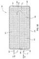
- FIG. 1Ais a cross-sectional view of one embodiment of an exemplary device according to one embodiment of the invention.
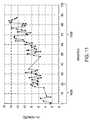
- FIG. 1Bis graph demonstrating the results of increased blood flow using the device according to one embodiment of the invention.
- FIG. 2Ais a perspective view of another exemplary device according to one embodiment of the invention.
- FIG. 2Bis a close-up partial exploded view of a portion of the thermal exchange unit according to one embodiment of the invention.
- FIG. 3Ais a perspective view of yet another exemplary device which is not yet folded nor enclosed according to one embodiment of the invention.
- FIG. 3Bis a perspective view of the exemplary device of FIG. 3A which is folded and enclosed according to one embodiment of the invention.
- FIG. 3Cis a top view of the exemplary device of FIG. 3A which is folded and enclosed according to one embodiment of the invention.
- FIG. 3Dis a side view of the exemplary device of FIG. 3A .
- FIG. 4Ais an exemplary device which is to be enclosed before a portion of an extremity is disposed according to one embodiment of the invention.
- FIG. 4Bis another exemplary device which is enclosed with a portion of an extremity disposed therein according to one embodiment of the invention.
- FIG. 4Cis another exemplary device with a portion of an extremity disposed and sealed therein according to one embodiment of the invention.
- FIG. 4Dis another exemplary device with a large portion of an extremity disposed and sealed therein according to one embodiment of the invention.
- FIG. 5Aillustrates one example of a thermal exchange unit according to one embodiment of the invention.
- FIG. 5Billustrates one example of a thermal exchange unit according to one embodiment of the invention.
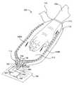
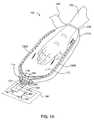
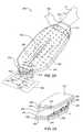
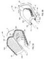
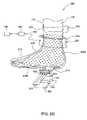
- FIG. 6Ais a side view of an exemplary lower extremity device according to one embodiment of the invention.
- FIG. 6Bis a perspective view of an exemplary lower extremity device which is not yet folded nor enclosed according to one embodiment of the invention.
- FIG. 6Cis a perspective view of an exemplary lower extremity device which is folded, enclosed and sealed according to one embodiment of the invention.
- FIG. 6Dis a side view of an exemplary lower extremity device according to one embodiment of the invention.
- FIGS. 6E-6Fare isometric views of various sized lower extremities positioned on the device illustrated in FIG. 6B according to one embodiment of the invention.
- FIG. 6Gis a side view of an exemplary lower extremity device according to one embodiment of the invention.
- FIG. 7illustrates an exemplary manifold with one or more fittings for tubing's according to an embodiment of the invention.
- FIG. 8illustrates one embodiment of a control unit connected to a device according to an embodiment of the invention.
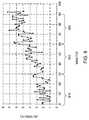
- FIG. 9is a graph demonstrating the results of increased blood flow using the device according to one embodiment of the invention.
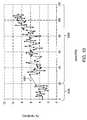
- FIG. 10is another graph demonstrating the results of increased blood flow using the device according to another embodiment of the invention.
- FIG. 11is another graph demonstrating the results of increased blood flow using the device according to yet another one embodiment of the invention.
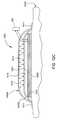
- FIG. 12Ais a side view of an exemplary device according to one embodiment of the invention.
- FIG. 12Bis a plan view of an exemplary device illustrated in FIG. 12A according to one embodiment of the invention.
- FIG. 12Cis a side view of an exemplary device according to one embodiment of the invention.
- Embodiments of the inventioninclude a method and a device for increasing blood flow and controlling the temperature of a mammal by applying a desired pressure to extremities of a mammal.
- the devicegenerally includes one or more collapsible and pliant body elements, capable of expanding from a first volume into an expanded second volume so the device can receive a portion of an extremity of the mammal therein and then be reduced from the expanded second volume into a pressurized third volume to conformably enclose the portion of the extremity.
- One or more thermal exchange unitscan be positioned in the one or more collapsible and pliant body elements.
- the temperature of the extremity of a mammalcan be regulated by providing a heated or cooled fluid medium or electric thermal energy to the one or more thermal exchange units.
- a heated or cooled fluid medium or electric thermal energyto the one or more thermal exchange units.
- the contact surface area between the extremity of a mammal and the one or more thermal exchange unitsis increased, due to the external atmospheric pressure acting on the pliant body elements against the skin of the extremity of the mammal.
- the application of pressureassures that sufficient contact and thermal heat transfer (heating or cooling) is provided to the extremity of the mammal.
- skin perfusioncan be improved.
- the pressure that is applied to the region surrounding the extremitycan be adjusted to increase the blood perfusion at the skin surface of the extremity, and also improve heat transfer to the blood and rest of the body. It is believed that regulating the pressure in the region around the mammal's extremity to allow an eternal pressure (e.g., atmospheric pressure) or force to create a contact pressure between the device components (e.g., thermal exchange units) and the extremity of about 13.5 mmHg will provide a desirable increase of blood perfusion. It is also believed that the exposure of the skin of the extremity to a sub-atmospheric pressure environment can also help the vasodilatation of the vasculature in the mammal's extremity. The vasodilatation of the vasculature may also help to increase the thermal exchange between the one or more thermal exchange units and the mammal's extremity.
- an eternal pressuree.g., atmospheric pressure
- the exposure of the skin of the extremity to a sub-atmospheric pressure environment
- the extremitycan be any kinds of the extremity of a mammal, such as an arm, a hand, a forearm, a forearm with an elbow, a hand with a wrist, a limb, a foot, a leg, a calf, an ankle, toes, etc., where Arteriovenous Anastomoses (AVAs) are located and/or when increased blood flow is desired.
- Arteriovenous Anastomoses (AVAs)which are connected to arteries and veins, are specialized blood vessels located primarily in the palms and fingers of the hands, the soles and toes of the feet, the cheeks, and the ears, etc.
- the device described hereinmay be adapted for use with other extremities that have vasculature structures suitable for the increasing blood flow methods described herein.
- Regulating the temperature of the mammal's extremitymay include elevating, cooling, and/or maintaining the mammal's temperature.
- the mammalmay be a human or other mammal. People at high risk of DVT, PE and other conditions, such as edema, wound swelling, venous stasis ulcers, diabetic wounds, decubitous ulcer, orthopedic surgery patients, spinal cord injured individuals, among others, can benefit from the invention.
- devices and methodsare provided to intervene thermal maladies (e.g., hypothermia and hyperthermia, etc.), to regulate the temperature of the extremity of a mammal when the thermoregulatory system of the mammal is compromised (e.g., by general anesthesia, local anesthesia, trauma, post-surgery conditions, or other factors), and/or to prevent deep vein thrombosis (DVT), pulmonary embolism (PE), and other diseases.
- thermal maladiese.g., hypothermia and hyperthermia, etc.
- thermoregulatory system of the mammale.g., by general anesthesia, local anesthesia, trauma, post-surgery conditions, or other factors
- DVTdeep vein thrombosis
- PEpulmonary embolism
- the devices and methods as described hereinare tested to be able to increase blood flow in the extremity of the mammal, which may include an appendage.
- optimal pressure to increase blood flowcould be about 13-14 mmHg, but that pressures between 1 and 80 mmHg, and more preferably 3 and 40 mmHg and more preferably 5 and 20 mmHg can increase blood perfusion. Pressures of approximately 14 mmHg combined with appropriate heat can increase blood flow, as a percent per minute of the volume of the appendage (in this case an arm) from a base level of between about 4% per minute to an increased level of about 8% per minute.
- the pressure applied to the skin by the devicecan be used to increase blood flow, which can be accomplished by a variety of methods including, but not limited to using atmospheric pressure to collapse a bag that has been evacuated or by pressurizing, or inflating, a cuff that encompasses a significant portion of appendage ( FIG. 6G ). Some results and embodiments are discussed below.
- a device for increasing blood flow and preventing deep vein thrombosisis provided to a mammal's extremity by using atmospheric pressure outside the enclosed extremity to increase the surface area of the contact between the skin of the mammal's extremity and one or more thermal exchange units to improve profusion, and by regulating the temperature of the mammal's extremity by controlling the temperature of the thermal exchange units.
- the external atmospheric pressureis used to press the one or more thermal exchange units against the mammal's extremity to provide as much thermal exchange as possible, and increasing the blood flow of the mammal's extremity.
- the inventionprovides a non-invasive, convenient apparatus for efficiently adjusting the temperature, applying vacuum, and/or applying compression pressure or forces, to the mammal's extremity to increase blood flow, promote venous blood return, prevent clots in the veins, and prevent DV, among others.
- FIG. 1Ais a cross-sectional view of one embodiment of a device 100 that is used to increasing blood flow by transferring heat to a mammal's extremity.
- the devicetransfers heat to and/or from a mammal's extremity, such as an arm, a hand, a forearm, a forearm with an elbow, a hand with a wrist, a limb, a foot, a leg, a calf, an ankle, toes, etc., where AVAs are located to provide an improved and efficient control of the patients temperature, and blood flow in the extremity.
- FIG. 1Billustrates plots of the core temperature of a patent as a function of time using various different methods to increase the temperature of the patient's core.
- Curves P 1 , P 2 and P 3illustrate the published results received using conventional techniques, such as convective heat transfer processes that exchange heat with the skin of the patient by delivering a flow of heated or cooled air.
- Curves C 1 and C 2illustrate the results received using the devices discussed herein, for example, device 100 illustrated in FIG. 1A .
- One characteristic feature of the conventional schemes illustrated by the curves P 1 , P 2 and P 3is the unwanted and immediate decrease in temperature of the patient for a period of time before a minimum temperature 195 is reached, and the patient's temperature finally starts to increase.
- FIG. 1Ais a cross-sectional view of one embodiment of a device 100 having one or more thermal exchange units 120 A, 120 B.
- the device 100includes an opening 112 formed in one or more body elements 110 that is used to enclose and receive a portion of an extremity 130 of a mammal.
- the device 100may also contain a sealing element 140 that is attached to the opening 112 , which is used to form a seal around the extremity 130 .
- the enclosed extremity 130 positioned within the internal region 113 of the device 100can then be evacuated to allow the atmospheric pressure external to the one or more body elements 110 to urge the one or more thermal exchange units 120 A, 120 B against the extremity 130 to provide a desired thermal exchange.
- the thermal environment formed around the extremitycan help to improve the control of the temperature and heat exchange between thermal exchange units and the extremity.
- the body element 110is generally designed so that it will occupy a minimum amount of space, or volume, so that it can be easily and conveniently folded, stored, or shipped.
- the body element 110is generally capable of being expanded from a minimized volume into an expanded volume for containing a portion of an extremity of a mammal therein. Under a pressurized condition, the volume or space of the body element 110 may be reduced from the expanded volume into a pressurized volume or space, such as a volume that conformally encloses the portion of the extremity 130 . It is generally desirable to use a body element 110 that is flexible enough to allow the pressure applied to each and every portion of the extremity 130 enclosed inside the device 100 to be evenly and equally distributed. In general, the minimized volume and the expanded volume are maintained under atmospheric pressure.
- Embodiments of the inventionprovide subjecting portions of an extremity of a mammal to a reduced pressure environment, preferably under vacuum or a negative pressure to increase contact surface area for thermal regulation, and adjusting the temperature of the extremity of the mammal, thereby increasing blood flow.
- a reduced pressure inside the device 100the portions of the body element 110 are pressed against extremity 130 .
- the pressure inside the internal region 113 of the pressurized volume of the body element 110 of the device 100can be regulated to a level lower than atmospheric pressure, such as a pressure level of about 0 mmHg to about ⁇ 80 mmHg by use of a pump 163 (e.g., mechanical pump).
- the body element 110is comprised of a collapsible and pliant material, including but not limited to, urethane, polyurethane, polypropylenes, polystyrenes, high density polyethylene's (HDPE), low density polyethylene's (LDPE), poly(vinyl chloride), rubbers, elastomers, polymeric materials, composite materials, among others.
- a collapsible and pliant materialincluding but not limited to, urethane, polyurethane, polypropylenes, polystyrenes, high density polyethylene's (HDPE), low density polyethylene's (LDPE), poly(vinyl chloride), rubbers, elastomers, polymeric materials, composite materials, among others.
- the body element 110can be made of disposable low cost materials.
- the collapsible and pliant materialmay comprise any suitable flexible material, for example, gas permeable thermoplastics, elastomeric materials, such as C-FLEXTM from Consolidated Polymer
- the collapsible and pliant materialcomprises a material that is temperature resistant.
- the body element 110can also be made of a biocompatible or hypo allergic material (and therefore safe for contact with the skin of a mammal), alternatively, the body element can be made of a transparent or semi-transparent material that allows viewing of the extremity 130 positioned therein.
- the body element 110may be made of materials that may be sterilized via autoclaving or ethylene oxide sterilization. This is especially important if the device is used during surgery where sterile conditions are very important.
- the thickness of the collapsible and pliant materialis not limited as long as it can sustain the pressurized conditions when the device 100 is used.
- a urethane material having a thickness from about 1.5 mils to about 12 milscan be used to pliantly conform to the shape and size of the portion of the extremity 130 contained therein.
- the thickness of the collapsible and pliant materialis not limited as long as it is compliant enough to substantially conform to the extremity and can sustain the desired pressurized conditions when the device 100 is in use.
- the one or more thermal exchange units 120 A, 120 Bcan be attached to one or more portions of the body element 110 and adapted to contact the portion of the extremity 130 under pressurized conditions and to increase, reduce, or maintain the temperature of the extremity 130 received therein.
- the thermal exchange unit 120 A, 120 Bcan be permanently or detachably placed inside the device 100 to provide thermal exchange for the extremity 130 received therein. Examples of some exemplary thermal exchange units 120 A, 120 B are illustrated and further discussed in conjunction with FIGS. 5A-5B .
- a thermal-exchange fluid mediumsuch as heated fluid, heated air, cooled fluid, or cooled air, etc.
- a fluid source 161can be provided into the thermal exchange units 120 A, 120 B via one or more fluid supply lines 124 and out of the device 100 via one or more fluid return lines 122 .
- the temperature of the one or more thermal exchange units positioned in the device 100may also be controlled by use of an electric pad, fluid type heat exchanging device, or any other suitable thermal exchange units, that are used individually or in combination. Thermal energy can be transferred from the thermal exchange unit to the extremity 130 during heating or from the extremity 130 to the one or more thermal exchange units during the process of cooling the extremity 130 .
- the thermal exchange units 120 A, 120 Bmay be a fluid heating pad having, for example, heated water delivered there through using a recirculation type heat exchanging system.
- the thermal exchange units 120 A, 120 Bmay be a pad having chemicals therein for heating or cooling.
- the thermal exchange units 120 A, 120 Bmay include an electric pad, as described in detail in co-pending U.S. provisional patent application Ser. No. 60/821,201, filed Aug. 2, 2006, which is incorporated by reference herein.
- thermal exchange units 120 A, 120 BGood contact with the thermal exchange units 120 A, 120 B is important in maximizing thermal transfer to the extremity 130 . Also, it is desirable to assure that the thermal exchange unit(s) will not loose contact the extremity 130 through normal jostling or positioning of the patient. Also, optimal contact and efficient thermal exchange between the thermal exchange units and the extremity 130 can be compromised when portions of the extremity 130 become arched or deformed due to the pressure differential acting on the extremity and the exterior of the device 100 when the internal region 113 is evacuated.
- the contact force caused by the pressure differentialis approximately equal to the contact surface area of the thermal exchange unit against the extremity 130 times the pressure differential. For example, the pressure differential may be approximately three pounds.
- the collapsible and pliant body elements of the devicehelps to assure that sufficient contact between the thermal exchange units 120 A, 120 B and the extremity 130 is maintained if the extremity becomes arched or deforms.
- the surface pressure created by the external atmospheric pressureurges the thermal exchange units 120 A, 120 B against the extremity 130 .
- thermal energycan be more evenly distributed to the extremity 130 .
- the materials of the body element 110 and the thermal exchange units 120 A, 120 Bare made of a flexible material, which can be pliant and easily collapsible to conform into the shape of the extremity and securely surround and enclose the portion of the extremity 130 to provide good contact between the surfaces of the extremity 130 and the thermal exchange units 120 A, 120 B (or the body element 110 ).
- the material for the thermal exchange units 120 A, 120 B and the body element 110are comprised of collapsible and pliant material to enhance the surface contact between the thermal exchange units 120 A, 120 B and the extremity 130 .
- the material of the body element 110thus may collapse against the thermal exchange units 120 A, 120 B due to the sub-atmospheric pressure or a vacuum pressure level achieved in the internal region 113 of the device 100 .
- the body element 110may include one or more apertures for attaching various fluid ports or pressure ports, such as a pressure port 116 , a pressure sensing port 118 , the fluid supply line 124 , and the fluid return line 122 . Accordingly, one or more thermal exchange supply lines (e.g., item 124 ) and one or more thermal exchange return lines (e.g., item 122 ) can be connected to one or more thermal sources (e.g., fluid source 161 ) through the one or more apertures formed in the body element 110 . In one embodiment, a manifold 114 may be formed or disposed on a portion of the body element 110 to provide the connections between the various external components to the device 100 .
- a manifold 114may be formed or disposed on a portion of the body element 110 to provide the connections between the various external components to the device 100 .
- the pressure sensing port 118 , the pressure port 116 , the fluid supply line 124 , and/or the fluid return line 122may be covered by protective sheaths.
- the manifold 114contains a pressure port 116 , a pressure sensing port 118 , the fluid supply line 124 , and the fluid return line 122 that are connected to various kinds of tubing and/or connectors to connect the various external components in the device 100 to the various components or regions positioned within the internal region 113 of the device 100 .
- the manifold 114may be connected to the one or more apertures, the one or more pressure ports, and the one or more thermal exchange units of the device 100 .
- the position of the apertures for the fluid ports or pressure portscan be located near any convenient portions of the body element 110 and can be close to the manifold 114 or grouped together for passing through the body element 110 via a single aperture.
- One example of a manifold 114is shown in FIG. 7 to incorporate quick connecting and disconnecting fittings.
- the sealing element 140is formed on a portion of the opening 112 and adapted to seal the portion of the extremity 130 when placed inside the internal region 113 of the body element 110 to allow a pressure to be applied to the extremity 130 .
- the sealing element 140may be adapted to allow a pressurized volume to be formed so that an even and equal pressure is applied on each and every position for the portion of the extremity 130 of the mammal.
- the sealing element 140is generally sized and used to seal the opening according to the size of the portion of the extremity 130 of the mammal.
- the sealing element 140may be made of a material that is biocompatible (and therefore safe for contact with the skin of a mammal) and capable of producing an airtight seal.
- the sealing element 140is detachably attached to the opening 112 .
- the sealing element 140is comprised of a disposable material, such as a disposable liner or an insert material.
- the material of the sealing element 140may be hydrogel, a sticky seal material, polyurethane, urethane, among others.
- the materialis hydrogel.
- Another exampleis a PS series thermoplastic polyurethane from Deerfield Urethane, Inc.
- Disposable sealing materialsmay be manufactured and packaged such that they are sterile before use and/or hypoallergenic to meet health and safety requirements.
- the sealing element 140may include an air permeable portion and/or made of a permeable membrane material or a breathable material to permit the flow of air, etc.
- the permeable portionmay be positioned near any portion of the body portion to provide permeable outlets, allowing the vacuum to have the proper effect on the extremity 130 and providing a barrier keeping the device 100 from contamination for the comfort of the patient.
- the pressurized volume defined by the body element 110 and sealing element 140is formed by applying a negative pressure to the pressure port 116 , which can be connected to a pump 163 , for reducing the pressure of the internal region 113 inside the device 100 .
- the pressure level inside the chamber 150can be monitored by a vacuum sensor 162 placed inside the pressurized volume or be in fluid communication or fluidly attached to the pressure sensing port 118 .
- One or more pressure portsmay also be positioned between the at least one pump 163 and the body element 110 .
- the sealing element 140is wrapped around the portion of the extremity 130 of the mammal top to seal the opening 112 .
- the air inside the device 100is pumped out via a pressure port 116 connected to a pump 163 to provide a vacuum or sub-atmospheric environment in the internal region 113 of the device 100 .
- the sealing element 140is one example of a seal that may be used with the device 100 , and in some cases it may be desirable not to use a seal at all. However, it is generally desirable provide a seal to reduce the leakage and thus reduce the amount of air that must be continuously removed from the apparatus during the use of the device 100 .
- a sealing element 140 that exerts too much force on the extremity 130may reduce or eliminate the return blood flow to the body, thus reducing the effectiveness of the device, and potentially creating adverse health effects.
- the sealing element 140may also be attached to the device 100 with mechanical fasteners or other fastening units, such as one or more mating rings which can snap into the device 100 .
- mechanical fasteners or other fastening unitssuch as one or more mating rings which can snap into the device 100 .
- Another exampleincludes the use of a tape with a removable liner, such as 3M removable tapes, etc., which can be removed when ready to use.
- the sealing element 140is a single use seal.
- the single use sealing element 140is attached to the device 100 , and the device and the sealing element 140 are disposed of after a single use.
- the sealing element 140may be removed from the device 100 and the device may be used repeatedly with another sealing element.
- the sealing element 140may comprise a strip of releasable adhesive tape ranging from 0.5 inches to 6 inches in width, e.g., a width large enough to cover the bottom of the extremity 130 .
- the sealing element 140may comprise an adhesive face and a backing portion.
- the sealing element 140is generally long enough that when wrapped end over end around the edge of the opening 112 , an overlap of about 0.5 inches or larger, such as about 2 inches, is present. The overlap is preferably not to encourage the user to wrap the sealing element 140 around the extremity too tightly and thus create a modest vacu-sealing force, e.g., less than 20 mm Hg.
- the material of the sealing element 140may comprise a releasable adhesive material for attachment to a mammal extremity in some portion and a more permanent adhesive in other portions thereof for attaching the sealing element 140 to the device 100 .
- the releasable adhesive materialmay be any of a wide variety of commercially available materials with high initial adhesion and a low adhesive removal force so that the sealing element 140 does not pull off hair or skin and create pain when it is removed.
- the releasable adhesivemay be a single use adhesive.
- the adhesive materialmay be thick and malleable so that it can deform or give, in order to fill gaps. Adhesives with water suspended in a polymer gel, e.g., a hydrogel, are generally effective.
- Tagaderm branded 3M adhesive(part No. 9841) which is a thin (5 mm) breathable adhesive that is typically used for covering burns and wounds.
- an electrocardiogram (EKG) adhesivesuch as 3M part No. MSX 5764, which is a thicker adhesive (25 mm).
- the sealing element 140should fasten such that there is no leakage of the vacuum.
- the sealing element 140has a backing that may be a thin, non-elastic, flexible material.
- the backingsupports the adhesive and keeps it from being pulled into the opening 112 when the internal region 113 is evacuated.
- the backingalso allows the adhesive to conform to both the shape of the extremity 130 and the shape of the opening 112 , as well as to fold in on itself to fill gaps that may be present in the vacu-seal around the extremity 130 .
- the backingprevents the adhesive from sticking to other surfaces.
- Commercially available polyethylene in thicknesses up to about 10 millimetersmay be used for the backing. Polyethylene that is thicker than about 10 millimeters may limit the adhesive's ability to fold on itself and fill in gaps.
- the backingmay also comprise any polymer that may be fabricated into a thin, non-elastic, flexible material.
- the sealing element 140comprises a backing has an adhesive disposed on two opposing adhesive faces to allow it to be attached to the body element 110 and the extremity 130 .
- 3M EKG adhesive products MSX 5764contains a supportive backing in between multiple layers of adhesive. Multiple layers of backing can also be used to provide support for the sealing element 140 .
- the opening 112 of the deviceis preferably close to the size of the patient's extremity to minimize the difference in dimensions that the sealing element 140 must cover.
- the smallest opening size that will accommodate the range of extremity dimensions, such as foot sizesis preferred. Minimizing the opening size reduces the force on the extremity 130 , which is approximately equal to the area of the opening 112 times the pressure differential.
- the sealing element 140is typically able to be formed of different sizes to accommodate extremity sizes down to the size of a small adult and up to various sizes of a large adult. For example, multiple opening sizes, such as small, medium, and large may be used to accommodate a wider range of foot sizes.
- the opening 112may be adapted to contract within a size range of the extremity 130 without constricting blood flow to further minimize this force and make the sealing process by the sealing element 140 easier.
- one or more stringsmay be used to tighten the opening 112 to the extremity 130 .
- external buckles, Velcro fasteners, and straps, among othersmay also be used to surround the opening 112 of the device 150 and secure the opening 112 around the extremity 130 .
- one or more portions of the body element 110may be made from transparent materials such that the functioning of the device and the condition of the extremity 130 may be monitored during use of the device.
- the body element 110may be divided into two or more body sections to be assembled into the device 100 and secured by one or more fastening units, such as Velcro fasteners, or conventional snaps.
- the device 100may further include a control system 164 that contains a controller 160 that is connected to various parts of the device 100 , including the pump 163 and vacuum sensor 162 connected to one or more of the pressure ports, the fluid source 161 connected to one or more of the fluid lines connected to the one or more thermal exchange units.
- the controller 160may be adapted to regulate the functions and process performed by the device 100 , including adjusting the fluid flow in and out of the thermal exchange units 120 A, 120 B, regulating the temperature of the thermal exchange units 120 A, 120 B, monitoring the pressure level inside the device 100 via one or more vacuum sensors 162 , adjusting the pump 163 speed and the vacuum level inside the device 100 , and monitoring the temperature of the extremity 130 received therein, among others.
- the devices described hereinmay include an in-use sensor indicating that the device is in use (e.g., vacuum switch).
- the in-use sensor and/or controller 160may indicate how many times the devices have been used.
- the devicecan be used in combination with a mechanical compression device or a pressurized compression device to help pump blood through the patient's body.
- the device 100can itself be modified to include one or more pressure-applying gas plenums positioned within or attached to the body element 110 in order to apply a compression force or positive gas pressure on the extremity 130 of a mammal, in addition to controlling the extremities temperature by delivering a thermally controlled fluid to the one or more fluid exchange units that are in contact with the extremity.
- FIG. 2Ais a perspective view of another example of a device 200 according to one or more embodiments of the invention.
- the device 200may include a thermal exchange unit 220 , a pressure port 216 , a pressure sensing line 218 , a fluid supply line 224 , a fluid return line 222 , an opening 112 for the extremity to be enclosed therein, and a sealing element 140 .
- a manifold 214may be formed for providing the connection between the various fluid ports or pressure ports, such as the pressure port 216 , the pressure sensing line 218 , the fluid supply line 224 , and the fluid return line 222 , and other external components.
- the thermal exchange unit 220that is permanently attached to the device 200 and composed of a collapsible and pliant material, including but not limited to, urethane, polyurethane, elastomers, polypropylenes, polystyrenes, high density polyethylene's (HDPE), low density polyethylene's (LDPE), poly(vinyl chloride), rubbers, polymeric materials, composite materials, among others.
- the thermal exchange unit 220is generally designed to allow a fluid medium to be delivered there through to exchange heat with an extremity. As a result, there is no need for a separate body element (see item 110 in FIG.
- thermal exchange unit 220can be used to enclose the extremity 130 by forming a internal region 213 , which can be evacuated.
- the body of the thermal exchange unit 220is capable of forming into a minimized volume for folding, storage, and/or shipping.
- the space enclosed by the thermal exchange unit 220 , or internal region 213can also be expanded so that the extremity 130 can be disposed therein.
- the internal volume 213 of the thermal exchange unit 220can be reduced under a pressurized condition to conformably apply even and equal pressure on the portion of the extremity 130 disposed inside the device 200 .
- the thickness of the material for the thermal exchange unit 220is not limited as long as it is compliant enough to substantially conform to the extremity and can sustain the pressurized conditions when the device 200 is used and the fluid medium can be delivered therein.
- a urethane material having a thickness of from about 1.5 mils to about 12 milscan be used to pliantly conform to the shape and size of the portion of the extremity 130 contained therein.
- Another possible materialmay include NTT-6000, which is a polyether polyurethane manufactured using USP Class V1 compliant materials.
- the NTT-6000 materialcan be a 2 mil gage material that is a natural color and is available from American Polyfilm, Inc. Branford, Conn. NTT-6000.
- the thermal exchange unit 220may be connected to the opening 112 through a body element 242 .
- the body of the thermal exchange unit 220can directly form the opening 112 without the use of an additional body element 242 .
- the device 200may include temperature sensors to measure the fluid in and out of the thermal exchange units 200 and to measure the surface temperature of the extremity 130 , such as a patient's body surface temperature.
- the device 200may further include a control system 164 having a controller 160 connected to various parts of the device 200 , including the pump 163 and vacuum sensor 162 connected to one or more of the pressure ports, the fluid source 161 connected to one or more of the fluid lines connected to the one or more thermal exchange units.
- the controller 160may be adapted to regulate the functions and process performed by the device 200 , including adjusting the fluid flow in and out of the thermal exchange units 220 , regulating the temperature of the thermal exchange units 220 , monitoring the pressure level inside the device 200 via one or more vacuum sensors 162 , adjusting the pump 163 speed and the vacuum level inside the device 200 , and monitoring the temperature of the extremity 130 received therein, among others.
- the thermal exchange unit 220is formed by bonding or sealing two layers (e.g., layers 231 and 232 ) of a collapsible and pliant material together to form a composite element 230 having a fluid plenum 233 formed between the bonded and sealed layers to allow a heat exchanging fluid to be delivered from the fluid source 161 there through.
- FIG. 2Bis a partially exploded cross-sectional view of a portion of the thermal exchange unit 220 according to an embodiment of the invention.
- the layers 231 and 232can be sealed (e.g., seal 234 ) by use of a heat sealing, gluing, or other conventional compliant layer bonding technique.
- the layers 231 and 232may composed of a collapsible and pliant material, including but not limited to, urethane, polyurethane, polypropylenes, polystyrenes, high density polyethylene's (HDPE), low density polyethylene's (LDPE), poly(vinyl chloride), rubbers, elastomers, polymeric materials, composite materials, among others.
- a collapsible and pliant materialincluding but not limited to, urethane, polyurethane, polypropylenes, polystyrenes, high density polyethylene's (HDPE), low density polyethylene's (LDPE), poly(vinyl chloride), rubbers, elastomers, polymeric materials, composite materials, among others.
- a plurality of dimples 240are formed between the layers 231 and 232 to form a stronger composite elements 230 that will not dramatically expand when a heat exchanging fluid is delivered from the fluid source 161 to the thermal exchange unit 220 .
- a separating feature 236is formed through a region of the composite element 230 to allow fluid delivered from the fluid supply line 224 to flow through the fluid plenum 233 and around the separating feature 236 before the fluid exits the thermal exchanging unit 220 and enters the fluid return line 222 .
- the separating feature 236may be formed by RF welding, thermal sealing, gluing, or bonding the layers 231 and 232 together.
- a composite element 230is formed on either side, or wraps around, the extremity 130 in the device 200 to provide improved thermal contact and heat exchanging properties.
- FIG. 3Ais a perspective view of a device 300 in its opened and unfolded position according to one embodiment of the invention.
- FIGS. 3B , 3 C, 3 Dillustrate a perspective view, a top view, and a side view of the device 300 which is folded and enclosed according to one embodiment of the invention.
- the device 300may include a singular body element being flat and unfolded.
- the device 300may include a first body element 310 A and a second body element 310 B, as shown in FIG. 3A .
- the first body element 310 A and the second body element 310 Bcan be folded, for example, through the direction of an arrow A, to form the opening 112 ( FIG. 3B ) and to enclose a portion of the extremity 130 of a mammal.
- the first body element 310 A and the second body element 310 Bmay be comprised of the same material as the body element 110 of the device 100 .
- the size of the opening 112may be sealed and reduced by a sealing element 342 .
- the material of the sealing element 342may be the same material as the sealing element 140 discussed above.
- the device 300generally further includes one or more thermal exchange units 320 A and 320 B capable of containing a thermal-exchange fluid medium therein.
- the first body element 310 A and the second body element 310 Bmay be connected to the opening 112 through a body element 343 .
- the body of the first body element 310 A and the second body element 310 Bcan directly form the opening 112 without the use of an additional body element 343 .
- the first body element 310 A, the second body element 310 B, and the additional body element 343are formed from a collapsible and pliant material, including but not limited to, urethane, polyurethane, polypropylenes, polystyrenes, high density polyethylene's (HDPE), low density polyethylene's (LDPE), poly(vinyl chloride), rubbers, elastomers, polymeric materials, composite materials, among others.
- a collapsible and pliant materialincluding but not limited to, urethane, polyurethane, polypropylenes, polystyrenes, high density polyethylene's (HDPE), low density polyethylene's (LDPE), poly(vinyl chloride), rubbers, elastomers, polymeric materials, composite materials, among others.
- the device 300is folded so that the edges 350 of the first body element 310 A and the second body element 310 B may be enclosed by an enclosing clip 352 , for example, through the direction of an arrow B ( FIG. 3B ), such that the opening 112 is formed for the portion of the extremity to be inserted therein.
- the mechanism by which the enclosing clips 352 can be used to enclose the edges 350 of the first body element 310 A and the second body element 310 Bmay vary and include fasteners, zippers, snaps, buttons, hydrogel coated tabs, conventional tape type materials, hook/loop type systems, among others.
- edges 350 of the first body element 310 A and the second body element 310 Bmay be reinforced such that the edges 350 can stayed together via the enclosing clip 352 and hold the portion of the extremity 130 in place until vacuum or reduce pressure is applied to the internal region 313 formed between the first body element 310 A and the second body element 310 B.
- a generalized port 325can be used to bundle up the various fluid ports and pressure ports together.
- the generalized port 325can be used to fluidly or electrically connect the controller 160 (see FIG. 3C ), the fluid source 161 , vacuum sensor 162 , and/or a pump 163 to the various components found in the internal region 313 of the device 300 .
- the generalized port 325may include a pressure port 316 , a pressure sensing line 318 , a fluid supply line 324 , and a fluid return line 322 therein.
- the generalized port 325may also be used to connect to one or more compression air plenums for applying a compression pressure on the portion of the extremity 130 .
- FIG. 4Ais another example of a device 400 according to one embodiment of the invention that is in an “open” position to receive an extremity 130 (See FIG. 4B ).
- FIG. 4Billustrates the device 400 which is configured to enclose a portion of the extremity 130 disposed therein according to one embodiment of the invention.
- the device 400includes a body element 410 which can be folded and/or rolled up and down to form the opening 112 to enclose a portion of the extremity 130 of a mammal.
- the body element 410may be comprised of the same material as the body element 110 of the device 100 .
- the device 400may further include one or more thermal exchange units 420 A and 420 B capable of containing a thermal-exchange fluid medium therein.
- the size of the opening 112 formed when the extremity 130 is enclosed within the device 400may be sealed by use of a sealing element 440 .
- the material of the sealing elementmay be the same material as the sealing element 140 .
- the device 400is unfolded and folded according to the direction of an arrow C to cover and enclose the thermal exchange units 420 A and 420 B and the extremity 130 .
- FIG. 4Billustrates the device 400 in an enclosed configuration.
- the edges 450 of the thermal exchange units 420 A and 420 Bmay be urged together by one or more enclosing clip 452 and the opening 112 can be formed for the portion of the extremity 130 to be inserted therein.
- the mechanism by which the enclosing clips 452 can be used to enclose the edges 450may vary and include fasteners, zippers, snaps, hydrogel coated tabs, conventional tapes, buttons, and hook/loop type systems, among others.
- the edges 450 of the thermal exchange units 420 A and 420 Bmay be reinforced such that the edges 450 can be sealed and snapped-locked tightly by the enclosing clips 452 .
- a generalized port 425can be used to bundle up the various fluid lines and pressure lines together that are connected to the controller 160 , the fluid source 161 , vacuum sensor 162 an/or a pump 163 ( FIG. 4B ).
- a manifold 414may be used to help connect and disconnect the various fluid ports and pressure ports between the generalized port 425 and the thermal exchange units 420 A and 420 B.
- FIGS. 4C and 4Dillustrate examples of the device 400 , such as device 400 A ( FIG. 4C ) and device 400 B ( FIG. 4D ), with a portion of an extremity 130 disposed and sealed therein according to one or more embodiments of the invention.
- the extremity 130 to be enclosed by the device 400 Acan be a hand, as shown in FIG. 4C , in which the device 400 A is shaped like a mitten or a glove.
- the one or more thermal exchange units 420are sized to heat the desired area of the extremity 130 that is positioned within the body element 410 .
- the internal region 413 of the device 400 Acan be evacuated and the thermal exchange unit(s) 420 can be temperature regulated by use of the controller 160 , fluid source 161 , vacuum sensor 162 an/or a pump 163 , which is schematically illustrated in FIG. 4C . While only a single thermal exchange unit 420 is shown n FIGS. 4C and 4D , this configuration is not intended to be limiting to the scope of the invention, and thus two or more thermal exchange units 420 may be positioned around various parts of the extremity 130 to improve perfusion.
- the extremity 130 enclosed in the devicemay be a large portion of an arm, or other appendage.
- the device 400 Bcan be shaped like an elongated glove to conformably enclose the arm.
- the increased surface area of the body enclosed and temperature controlled by use of the thermal exchange unit(s) 420 shown in FIG. 4D versus FIG. 4Cmay be useful to help more rapidly and/or easily control the subjects body temperature during use.
- a generalized port 425can be used to bundle up various fluid ports and pressure ports together and connected to the controller 160 , the fluid source 161 , vacuum sensor 162 an/or a pump 163 .
- FIG. 5Aillustrates one example of the thermal exchange unit 120 , such as the thermal exchange units 120 A, 120 B, 220 , 320 A, 320 B, and 420 discussed herein, according to one embodiment of the invention.
- the thermal exchange unit 120includes a thermal exchange body 546 having sides 546 A and 546 B.
- One side (e.g., side 546 B) of the thermal exchange body 546includes a plurality of thermal contact domes 548 that have a thermal contact surface 547 that can be applied to a portion of the extremity 130 .
- the diameter of the thermal contact surfaces 547 and the shapes or sizes thereofcan vary such that the sum of the total area of the thermal contact surfaces 547 can be maximized.
- the thermal exchange unit 120may further include the thermal fluid supply line 124 and the thermal fluid return line 122 connected to a thermal fluid source (e.g., fluid source 161 FIG. 1A ) for circulating a thermal fluid medium through the thermal exchange body 546 of the thermal exchange unit 120 .
- a thermal fluid sourcee.g., fluid source 161 FIG. 1A
- the material of the thermal exchange body 546may be any flexible, conductive and/or durable material, for example, any of the materials suitable for the body element 110 .
- the thermal exchange body 546is made of a flexible material which can easily conform to the shape of the extremity 130 .
- the thermal contact domes 548are made of a rigid material to provide rigid contacts to the extremity 130 .
- the material of the thermal contact domes 548may be a material which provides high thermal conductivity, preferably much higher thermal conductivity than the material of the thermal exchange body 546 .
- the thermal contact domes 548may be made of aluminum, which provides at least 400 times higher thermal conductivity than plastics or rubber materials.
- the thermal exchange unit 120can be formed and assembled through RF welding. In another embodiment, the thermal exchange unit 120 may be formed and assembled through injection molding. There are many possible ways to design and manufacture the thermal exchange body 546 to provide a flexible thermal exchange unit that does not leak. In one embodiment, the thermal exchange unit 546 is formed by bonding a compliant material that is sealed using conventional techniques at a joint 549 .
- the thermal exchange unitis formed from layers of several materials bonded together to form internal fluid flow paths for thermal fluids to be delivered therein.
- the multiple layer configurationmay result in uneven surfaces, due to the presence of the internal fluid flow paths.
- the resulting bumpy surfacesmay provide less contact, thereby reducing surface area needed for maximum thermal transfer.
- the thermal exchange body 546may also be formed using a low thermal conductivity material, such as polyurethane.
- the thermal exchange body 546may be covered by one or more backing sheets such that a flat and even contact is made to the extremity.
- the backing sheetcan be made of high thermal conductive material to provide high thermal conductivity between the thermal exchange unit 120 and the extremity.
- the backing sheetsmay be made of a thin metal sheet, such as aluminum (like a foil) or other metal sheets. In general, aluminum or other metal materials may provide higher thermal conductivity than plastics or rubber, e.g., at least 400 times higher.
- FIG. 5Billustrates another embodiment of the thermal exchange unit 120 that is formed using two layers of a compliant material 541 that are sealed at the edge region 535 by use of an RF welding, thermal sealing, gluing or other bonding process to form a sealed main body 542 .
- the main body 542may have an inlet port 544 and an outlet port 543 that are in fluid communication with the fluid source 161 , and the fluid supply line 124 and fluid return line 122 , respectively.
- the region formed between the two layers of the compliant material 541is thus used as a fluid plenum that can receive (see arrow A 1 ) and then exhaust (see arrow A 3 ) the thermal fluid medium from the fluid source 161 .
- a separating feature 536is formed in the thermal exchange unit to separate the fluid delivered into the inlet port 544 and the outlet port 543 , and thus allow the thermal exchanging fluid to follow a desirable path through fluid plenum to optimize and/or improve efficiency of the heat transfer process.
- the fluid flow pathsequentially follows the arrows A 1 , A 2 and A 3 .
- the separating feature 536can be formed in the sealed main body 542 by RF welding, thermal sealing, gluing or other bonding process to bond the two layers of the compliant material 541 together.
- a plurality of dimples 540are formed between the layers of compliant material 541 in the sealed main body 542 by RF welding, thermal sealing, gluing or other bonding process to form a structure that will not expand when a heat exchanging fluid is delivered to the internal region of the sealed main body 542 .
- the thermal exchange unit 120is formed and assembled through RF welding or thermal sealing techniques. In another embodiment, the thermal exchange unit 120 may be formed and assembled through injection molding. In one embodiment, the thermal exchange unit 120 illustrated in FIG.
- 5Bis formed from a pliant material, including but not limited to, urethane, polyurethane, polypropylenes, polystyrenes, high density polyethylene's (HDPE), low density polyethylene's (LDPE), poly(vinyl chloride), rubbers, elastomers, polymeric materials, composite materials, among others.
- a pliant materialincluding but not limited to, urethane, polyurethane, polypropylenes, polystyrenes, high density polyethylene's (HDPE), low density polyethylene's (LDPE), poly(vinyl chloride), rubbers, elastomers, polymeric materials, composite materials, among others.
- one or more thermal exchange units 120may be an electric pad having one or more electric wires connected to a power source.
- the power sourcemay be a low voltage DC current power source.
- the one or more thermal exchange unitsmay include a thermocouple to monitor the temperature and a thermo switch to automatically shut off the electric power when the temperature of the electric pad passes a safety level.
- the thermal exchange units as described herein(e.g., reference numerals 120 , 120 A, 120 B, 220 , 320 A, 320 B, and 420 ) according to embodiments of the invention generally provide thermal exchange surfaces, with increased surface area, to heat, cool, and/or regulate the temperature of an extremity of a mammal.
- the thermal exchange unitscan be used to regulate the blood flow in an appendage by a variety of means. For instance, applying a temperature to a hand of about 0° C. to 10° C. can cause an increase in the average blood flow due to a phenomenon called the “hunting response” which keeps hunters and fisherman from getting frostbite while working in the extreme cold with their bare hands.
- Different individualsrespond differently to cold applied to the hands, and in a some well known laboratory tests, application of cold to the hands of a person from the Indian sub-continent improved average blood flow, but not as much as the same treatment improved the average blood flow in the typical Eskimo.
- the perception of warmthis enough to improve blood flow.
- a 23° C. (room temperature) water padfeels cool in intimate contact with the leg of a normothermic subject who otherwise feels warm, and the “COOLNESS” of the pad can measurably reduce blood flow in the leg.
- this same 23° C. (room temperature) water padfeels warm in comparison, so that it can actually increase blood flow in the same leg. Therefore the temperature blood flow relationship is determined by both perceived warmth and applied temperature. The application of the heat above the core body temperature is also able to increase blood flow.
- one or more thermal exchange unitsindividually or in combination, can be positioned and attached to one or more portions of the body element of the invention to provide thermal exchange and regulate the temperature of a mammal's extremity provided inside the devices as described herein.
- one or more thermal exchange unitscan be pre-assembled inside the devices.
- one or more thermal exchange unitscan be assembled into the devices prior to use.
- FIG. 6Ais a side view of one example of a device 600 , which may be used increase blood flow and control the temperature of a lower extremity of a mammal, such as a foot, according to one embodiment of the invention.
- the device 600includes a body element 610 for forming a pressurized volume, one or more thermal exchange units 620 A, 620 B positioned on various sides/portions of the extremity 130 , the opening 112 for containing the extremity 130 , and a sealing element 640 attached to the opening 112 .
- An additional sealing elementsuch as a sealing element 642 , may be used to adequately seal the extremity 130 within an internal region 613 of the device 600 .
- the body element 610is generally be flat or occupying a minimized space or volume such that the device 600 can easily and conveniently be folded, stored, or shipped.
- the body element 610is capable of expanding from the minimized volume into an expanded space or volume for containing a portion of an extremity of a mammal therein. Under a pressurized condition, the volume or space of the body element 610 is reduced from the expanded volume into a pressurized volume, such as a volume to conformably enclose the portion of the extremity 130 . As a result, the pressure applied to the extremity 130 enclosed inside the internal region 613 of the device 600 is distributed evenly and equally. The minimized volume and the expanded volume can be maintained under atmospheric pressure.
- the body element 610may be comprised of the same collapsible and pliant material as the body element 110 , such as a transparent or semi-transparent material that allows viewing of the extremity 130 positioned therein.
- the thickness of the collapsible and pliant materialis not limited as long as it can sustain the pressurized conditions when the device 600 is used; for example, a thickness of from about 0.5 mils to about 20 mils, such as about 1.5 mils to about 12 mils, can be used to pliantly conform to the shape and size of the portion of the extremity 130 contained therein.
- the materials of the body element 610 and the thermal exchange units 620 A, 620 Bare made of a flexible material, which can be pliant and easily collapsible to conform into the shape of the extremity 130 and securely surround and enclose the portion of the extremity 130 .
- the material for the thermal exchange units 620 A, 620 B and the body element 610are generally comprised of collapsible and pliant material similarly discussed above in conjunction with thermal exchange units (e.g., reference numerals 120 , 120 A, 120 B) and body element 110 .
- the materials used in the thermal exchange units 620 A, 620 B and/or the body element 610are generally selected to allow good contact between the surfaces of the extremity 130 and the thermal exchange units 620 A, 620 B and/or the body element 610 when a sub-atmospheric pressure or a vacuum pressure level is achieved within the internal region 613 of the device 600 .
- the one or more thermal exchange units 620 A, 620 B, etc.are attached to one or more portions of the body element 610 and adapted to contact a portion of the extremity 130 that is under the pressurized condition, and to increase, reduce, or maintain the temperature of the extremity 130 received therein.
- the thermal exchange unit 620 A, 620 Bcan be permanently or detachably placed inside the device 600 to provide thermal exchange for the extremity 130 received therein.
- the thermal exchange units discussed in conjunction with FIG. 5A or 5 Bcan be adapted to meet the configuration requirements of the thermal exchange units 620 A, 620 B shown in FIGS. 6A-6C .
- the thermal exchange unitmay include an electric pad, as described in detail in co-pending U.S. provisional patent application Ser. No. 60/821,201, filed Aug. 2, 2006, which is incorporated by reference herein.
- the body element 610may include one or more apertures for attaching various fluid ports or pressure ports, such as a pressure port 616 , a pressure sensing port 618 , the fluid supply line 624 , and the fluid return line 622 , among others. Accordingly, one or more thermal exchange supply lines and one or more thermal exchange return lines can be connected to one or more thermal sources through the one or more apertures on the body element 110 . As shown in FIG. 6A , one or more tubing's, lines, and ports can be bundled together and connected to a manifold 614 to allow the fluid sources 161 , pumps 163 , vacuum sensor 162 and/or a controller 160 to be easily connected for easy transportation and operation. In one embodiment, the manifold 614 , as shown in FIG.
- the manifold 614may be formed on a portion of the body element 610 for connecting the various fluid ports or pressure ports to pass through the one or more apertures of the body element 610 to other vacuum manifold, fluid sources outside of the device 600 through various kinds of tubing's and/or manifold connectors.
- the manifold 614may be connected to the one or more apertures of the body element 610 , the one or more pressure ports and the one or more thermal exchange units of the device 600 .
- FIG. 6Dillustrates another configuration of the device 600 in which the manifold 614 is attached to a desired region of the body element 610 to provide a central place where connections can be made to the internal and external components in the device 600 .
- the sealing element 640is formed on a portion of the opening 112 and adapted to seal the portion of the extremity 130 when placed inside the pressurized volume of the body element 610 so that a pressurized condition can be applied to the mammal's extremity.
- the sealing element 640may be made of the same material as the sealing element 140 ( FIG. 1A ) and can be attached or detachably attached to the opening 112 .
- the sealing elementcan be used for contacting with the skin of a mammal and capable of producing an airtight seal.
- the pressurized volume defined by the body element 610 and the sealing element 640 of the device 600is created by applying vacuum or negative pressure to the pressure port 616 , which can be adapted to be connected to a pump 163 ( FIG.
- the pressure level inside the chamber or the pressurized, reduced volume enclosed by the body element 610can be monitored by a vacuum sensor 162 placed inside the pressurized volume or space attached to the pressure sensing port 618 .
- One or more pressure portsmay be adapted to be connected to at least one pump 163 on one end and the body element 610 on the other end.
- the device 600can be used in combination with a mechanical compression device or a pressurized compression device.
- the devicecan itself be modified to include one or more pressure-applying gas plenums in order to apply pressurized compression forces, or a positive gas pressure to an extremity of a mammal (e.g., in the internal region 613 ), while also applying a thermal controlled fluid medium to a fluid exchange unit contacting the extremity and/or applying vacuum or negative pressure to a portion of the extremity.
- FIG. 6Bis a perspective view of an exemplary lower extremity device which is not yet folded nor enclosed by the body element 610 .
- FIG. 6Cis a perspective view of an exemplary lower extremity device which is folded, enclosed and sealed according to one or more embodiments of the invention.
- the device 600may include a singular body element 610 capable of laying flat, rolled and/or unfolded, as shown in FIG. 6B .
- the device 600may include more than one body elements 610 .
- the device 600further includes one or more thermal exchange units 620 A and 620 B capable of containing a thermal-exchange fluid medium therein.
- the body element 610 and the thermal exchange units 620 A, 620 Bcan be folded, for example, through the direction of arrows D, to enclose a portion of the extremity 130 of a mammal. In operation the device 600 is folded by securing the positions of the thermal exchange units 620 A, 620 B and adjusting accordingly to the size of the extremity 130 .
- the thermal exchange units 620 A, 620 B and the body element 610can be properly folded, secured, and/or adjusted through one or more enclosing clips 652 located on one or more positions on the thermal exchange units 620 A, 620 B and the body element 610 .
- the one or more enclosing clips 652can be, for example, Velcro type fasteners, as shown in FIGS. 6B and 6C , or another other suitable, clips, fasteners, zippers, snaps, tabs, tongs, adhesives, Velcro fasteners, hydrogel coated tabs, conventional tapes, buttons, occlusion cuff, hook/loop type systems, etc. before or after a leg is positioned therein.
- the body element 610can then be positioned over the thermal exchange units 620 A and 620 B to form the opening 112 in which the extremity 130 is disposed.
- the size of the opening 112may be sealed by the sealing element 640 ( FIG. 6A ).
- a generalized port 625can be used to bundle up various fluid ports and pressure ports together and connected to the controller 160 , the fluid source 161 , vacuum sensor 162 an/or a pump 163 .
- the one or more tubing's, lines, and portscan be bundled together and connected to the manifold 614 for connecting to thermal regulation fluid sources, vacuum pumps, and/or a controller unit (not shown) for easy transportation and easy connection.
- the manifoldis convenient located to near the front toe portions of a foot.
- FIG. 6Dillustrates a convenient connection near the heal of a foot.
- the thermal exchange units 620 A, 620 Bcontain one or more relieved regions 623 that allow for movement of the extremity 130 during the use of the device 600 .
- the placement of the relieved regions 623 in the thermal exchange units 620 A, 620 Bmay be strategically positioned to only allow heat transfer to desired regions of the extremity 130 . It has been found that exchanging heat with certain areas of certain extremities can be unpleasurable. For example, it has been found that providing heat to the heal region of a foot can be an unpleasurable experience for some subjects, and thus, as shown in FIG. 6C , the heal region of the thermal exchange units 620 A, 620 B has been removed to form the relieved region 623 at the heel.
- the heat transfer portion of the thermal exchange units 620 A, 620 B near the heal regionis removed to remove or prevent the process from being unpleasant.
- FIGS. 6E and 6Fillustrate a plan view of an unfolded device 600 similar to the device illustrated in FIG. 6B that can be used to improve the profusion and regulate the temperature of patients having different sized extremities 130 .
- the design of the device 600can be deigned to allow various sized extremities 130 , as here a foot, to be received and easily positioned within the same sized device 600 .
- the enclosing clips 652(not shown in FIGS. 6E and 6F ) the device 600 may be adjusted to fit different sized extremities, such as different sized feet.
- the device 600may include one or more body elements 610 each having an internal region 613 and one or more thermal exchange units disposed therein, such as an first body element for forming a first vacuum chamber on the foot portion of a leg and a second body element for forming a second vacuum chamber on the calf portions up to or near a knee of a leg.
- one single vacuum chambermay be formed into the device 600 for the whole leg portion of a mammal.
- FIGS. 12A-12Billustrates an embodiment of the invention in which a device 1400 can be positioned over a desired portion of skin 1431 of a mammal 1430 to increase the blood flow and control the temperature of the mammal 1430 .
- FIG. 12Ais a cross-sectional side view of the device 1400 that has been applied to the skin 1431 of a mammal 1430 .
- FIG. 12Billustrates a plan view of the device 1400 that has been applied to the skin 1431 of the mammal 1430 .
- the device 1400generally contains body element 1410 and one or more thermal exchange units 1420 .
- the body element 1410generally contains a sealing element 1411 and compliant element 1412 .
- the body element 1410 componentscan be made of a disposable low cost material, a biocompatible material, a material that can be sterilized, and/or a hypo allergic material similar to the materials discussed above in conjunction with the body element 110 .
- the compliant element 1412is generally formed from a collapsible and pliant material, including but not limited to, urethane, polyurethane, polypropylenes, polystyrenes, high density polyethylene's (HDPE), low density polyethylene's (LDPE), poly(vinyl chloride), rubbers, elastomers, polymeric materials, composite materials, among others.
- the compliant element 1412can be made of a transparent or semi-transparent material that allows viewing of the skin 1431 region of the mammal 1430 .
- the thickness of the compliant element 1412is not limited as long as it can sustain the pressurized conditions when the device 1400 is used. In one example, a thickness from about 1.5 mils to about 12 mils can be used to pliantly conform to the shape and size of the portion of the skin 1431 contained therein.
- the sealing element 1411is generally used to form a seal to the skin 1431 of the mammal 1430 so as to enclose the one or more thermal exchange units 1420 in an internal region 1413 .
- the sealing element 1411is generally designed to form a seal between the body element 1410 and the skin to allow a pressurized condition to be applied within the formed internal region 1413 by use of the control system 164 and the other supporting equipment discussed above (e.g., reference numerals 160 - 163 ).
- the sealing element 1411can be made of a sticky seal material, such as hydrogel, polyurethane, urethane, among others. Another example is a PS series thermoplastic polyurethane from Deerfield Urethane, Inc.
- Disposable sealing materialsmay be manufactured and packaged such that they are sterile before use and/or hypoallergenic to meet health and safety requirements.
- the sealing element 1411may include an air permeable portion and/or made of a permeable membrane material or a breathable material to permit the flow of air.
- the one or more thermal exchange units 1420are generally similar to the devices discussed above in conjunction with FIGS. 5A-5B .
- the one or more thermal exchange units 1420have an insulating layer 1421 disposed on one or more sides of the device to reduce heat loss to environment away from the skin 1431 and/or improve the heat transfer process to the skin 1431 .
- the control system 164 componentsare used to create a pressurized condition in the internal region 1413 by use of the various fluid ports or pressure ports, such as a pressure port 1416 , a pressure sensing line 1418 , the fluid supply line 1424 , and the fluid return line 1422 that pass through one or more apertures formed in the body element 1410 .
- the internal region 1413is evacuated by use of a vacuum pump (not shown) that is connected to the pressure port 1416 to create a vacuum condition in the internal region 1413 .
- the sub-atmospheric pressure created in the internal region 1413will cause the atmospheric pressure external to the device 1400 to urge the compliant element 1412 against the one or more thermal exchange units 1420 and/or skin 1431 to increase the blood flow and control the temperature of the mammal 1430 .
- the device 1400can be positioned on any open area of the subject, such as positions on a mammal's back, chest, thigh, or neck to increase the blood flow and control the temperature of the subject.
- the device 1400contains a second region 1414 that is positioned between a first body element 1410 A and a second body element 1410 B in which a gas is delivered to achieve a positive pressure therein to cause the second body element 1410 B to push against the one or more thermal exchange units 1420 and skin 1431 .
- the pressure delivered in the second region 1414can be any desirable pressure, such as between about 1 mmHg to about 80 mmHg above atmospheric pressure.
- the device 1400can be positioned on any open area of the subject, such as positions on a human's back, chest, thigh, or neck to the blood flow and control the temperature of the subject by application of pressure to the second region 1414 and thermal control of the one or more thermal exchange units 1420 .
- the devicessuch as devices 100 - 600 and 1400 may include one or more compression pads around one or more portions of the one or more body elements containing an extremity.
- the device 600includes an inflatable cuff assembly 680 that is positioned around one or more portions of the body element 610 .
- Each inflatable cuff assembly 680may include one or more air pockets (i.e., internal sealed region within the inflatable cuff assembly 680 ) that are connected to a fluid tubing 682 and fluid delivery device 681 so that the air pockets can be filled with air or various fluids when the extremity 130 is positioned inside the device 600 to cause a compression force on the extremity 130 .
- the pressure within the air pockets in the compression padcan controlled using the air or fluids delivered from the fluid delivery device 681 to provide a bellow-like motion to apply various compression pressures or pressurized forces on portions of the extremity 130 intermittedly, consecutively, or otherwise in a time appropriate manner.
- the one or more thermal exchange units 620 and inflatable cuff assemblies 680 of the device 620can be positioned in an overlapping configuration or separately on one or more portions of the body element of the device. It is believed that applying pneumatic compression pressure or pressurized force on portions of the extremity 130 may increase blood flow within the leg, prevent clotting and blood pooling in the veins, and prevent deep vein thrombosis.
- the inflatable cuff assembly 680may include an inflatable cuff 683 (e.g., conventional inflatable cuff, flexible bladder), fluid delivery device 681 (e.g., mechanical pump), and a fluid tubing 682 that connects the fluid delivery device 681 and a sealed internal region of the inflatable cuff 683 to allow a delivered fluid to inflate and deflate the inflatable cuff 683 to a desired pressure at a desired time.
- an inflatable cuff 683e.g., conventional inflatable cuff, flexible bladder
- fluid delivery device 681e.g., mechanical pump
- a fluid tubing 682that connects the fluid delivery device 681 and a sealed internal region of the inflatable cuff 683 to allow a delivered fluid to inflate and deflate the inflatable cuff 683 to a desired pressure at a desired time.
- the inflatable cuff assembly 680 designcan be used in conjunction with the other components discussed herein to transfer heat between the extremity and the one or more thermal exchanging devices, and also actively pump blood within the extremity by the use of sequential compression forces applied to the extremity by the inflatable cuff 683 and the fluid delivery device 681 that are in communication with the controller 160 .
- FIG. 7illustrates an example of a manifold 714 having one or more fittings that are used to connect the various gas, vacuum or fluid lines to various components internal and external to the device 700 according to one or more embodiments of the invention.
- the manifold 714can be attached to the one or more body elements and thermal exchange units of the device through one or more apertures on the body elements and the thermal exchange units.
- FIG. 7is a partial cut-away view that schematically illustrates a device 700 that contains the various components discussed above in conjunction with the device 100 - 600 and 1400 and the manifold 714 is generally useful in any of the configurations discussed herein in.
- the manifold 714is used in place of the manifolds 114 , 214 , 325 , 414 , and 625 discussed above.
- the manifold 714generally contains one or more fluid ports or pressure ports, such as a pressure port 716 , a pressure sensing line 718 , a fluid supply line 724 , and a fluid return line 722 , which can be connected to the manifold body 715 or integrally formed using injection molding, heat stacking, adhesives or other manufacturing methods. Accordingly, quick connect fittings or connectors can be incorporated to provide a connection point to interface the thermal exchange units, fluid pads, other heating components, electric pads, vacuum lines, pressure sensing lines, etc.
- the manifold 714may include connectors 730 , 732 , 734 , 736 , such as a quick connect type connector similar to CPC Colder Products Company in St, Paul, Minn.
- the manifold 714can be made out of injection molded plastic materials for its low cost, or any other suitable materials.
- a sealis generally formed between the manifold 714 , the various one or more fluid ports or pressure ports (e.g., reference numerals 716 , 718 ), and the body element 710 (e.g., similar to body elements 110 , 210 ) to allow a desired pressure to be reached in the internal region 713 of the device 700 by use of the pump 163 .
- the seal formed between the body element 710 and the various components of the manifold 714can be created using conventional adhesives, mechanical force, or O-rings to name just a few.
- the manifold 714may be connected to the inlet of the thermal exchange units 720 A and 720 B, which is similar to the devices discussed in conjunction with FIG. 5A-5B , using the fluid supply line 724 through one or more fluid supply fittings 754 and conventional tubing 753 that is in fluid communication with the connector 732 and the fluid supply line 161 A of the fluid source 161 .
- the outlet of the thermal exchange units 720 A and 720 Bis connected to the fluid return line 722 through one or more fluid supply fittings 752 and conventional tubing 755 that is in fluid communication with the connector 730 and the return fluid line 161 B of the fluid source 161 .
- the internal region 713 of the device 700is connected to the pump 163 which is connected to the pressure port 716 that contains a connector 736 contained in the manifold 714 , and a fitting 756 that is disposed within the internal region 713 of the device 700 .
- the internal region 713 of the device 700may also be connected to the vacuum sensor 162 which is connected to the pressure sensing line 718 that contains a connector 734 that is connected to the manifold 714 , and a fitting 758 that is disposed within the internal region 713 of the device 700 .
- a hand, a forearm, a foot, a leg, an upper extremity, or a lower extremityis disposed within the opening 712 of the device 700 and enclosed within the one or more body elements 710 with one or more thermal exchange units 720 A, 720 B attached thereon and the manifold 714 attached thereto.
- the devicemay need to be assembled by folding, rolling one or more body elements and enclosed with one or more enclosing clips.
- one or more detachable thermal exchange unitsmay be pre-assembled inside the device or may be assembled upon disposing an extremity into the device. Then, a vacuum sealing portion 741 of the seal element 740 is wrapped around the opening of the device to form a tight seal and prevent air from entering the space between the extremity and the device.
- a fluid sensing assembly 760is disposed within the fluid supply line 161 A to sense the temperature of the fluid entering the one or more thermal exchange units 720 A, 720 B so that heating or cooling elements contained within fluid source 161 can be controlled by the controller 160 .
- the fluid sensing assembly 760generally contains a body 762 and one or more sensors 761 that are in thermal communication with the fluid being delivered to the one or more thermal exchange units 720 A, 720 B.
- the one or more sensors 761may be a thermistor, RTD, thermocouple, or other similar device that can be used to sense the temperature of the fluid flowing through the body 762 and the fluid supply line 161 A.
- the controller 160is adapted to control all aspects of the processing sequence.
- the controller 160is adapted to control the fluid source 161 , the pump 163 , and all other required elements of the device 700 .
- the controller 160is generally configured to receive inputs from a user and/or various sensors (e.g., vacuum sensor 162 , fluid sensing assembly 760 ) in the device and appropriately control the components in accordance with the various inputs and software instructions retained in the controller's memory.
- the controller 160generally contains memory and a CPU which are utilized by the controller to retain various programs, process the programs, and execute the programs when necessary.
- the memoryis connected to the CPU, and may be one or more of a readily available memory, such as random access memory (RAM), read only memory (ROM), floppy disk, hard disk, or any other form of digital storage, local or remote.
- Software instructions and datacan be coded and stored within the memory for instructing the CPU.
- the support circuitsare also connected to the CPU for supporting the processor in a conventional manner.
- the support circuitsmay include cache, power supplies, clock circuits, input/output circuitry, subsystems, and the like all well known in the art.
- a program (or computer instructions) readable by the controller 160determines which tasks are performable in the device.
- the programis software readable by the controller 160 and includes instructions to monitor and control the process based on defined rules and input data.
- FIG. 8illustrates one embodiment of the control system 864 that is connected to various parts of a device 800 according to an embodiment of the invention.
- the device 800 and control system 864is similar to the devices (e.g., reference numbers 100 - 700 ) and control system 164 discussed above in conjunction with FIGS. 1-7 .
- the control system 864generally contains a controller module 860 having the controller 160 therein that houses all the electronics and mechanical parts which are required to regulate the temperature, vacuum pressure level, and compression pressurized force provided to the pressurized volume of the device.
- the control system 864typically includes, for example, a pump 163 , a vacuum sensor 162 , conventional tubing 824 , a fluid source 161 , a fluid flow sensor 852 , a fluid sensing assembly 760 , and a temperature sensor 810 .
- the temperature sensor 810is generally a device that is used to measure the temperature of the patient while the process of increasing the blood flow and controlling the temperature of the patient is being performed. Temperature of the patient can be measured in the ear, mouth, on the skin, or rectally using an appropriate conventional temperature sensing device.
- the control system 864may also contain a thermal exchange medium pump, a heater, a cooler, thermocouples, a heating medium pump, a proportional-integral-derivative (PID) controller for process control of the vacuum and the temperature, one or more power supplies, display panels, actuators, connectors, among others, that are controlled by the controller 160 .
- PIDproportional-integral-derivative
- the settings and current readings of the various elements in the of the control system 864may be conveniently positioned onto a display panel (e.g., lighted display, CRT) which provides an operator interface.
- the controller 160may contain additional electronics for optimal operation of the device 800 of the invention.
- the vacuum control and temperature controlmay be controlled by two different controllers.
- the control system 864may provide safety features including a device shutdown feature that is activated if the device sensors, such as the temperature and pressure sensors, fail or become disconnected.
- the control system 864may also include an alarm circuit or an alert signal if the temperature of the apparatus is not regulated correctly.
- a relief valvemay be provided within the vacuum loop of the device such that the chamber may be vented if the vacuum within the chamber exceeds a certain level.
- a temperature probe 862can be provided to measure the temperature of a portion of a mammal other than a foot, leg, or other extremity where the device is attached to.
- a tympanic membranecan be attached to the ear canal as a temperature sensor 810 to provide core temperature reading.
- a reference temperature for the humansuch as a patient
- Other sensorsmay include patient's blood flow and blood pressure and heart rate. These data are important to proper patient health care keeping the patient at normal temperature range and from various thermal maladies.
- the temperature of the skin in the devicecould be measured to indicate if the body portion is in a state of vasoconstriction or vasodilatation or what temperature the skin is compared two device fluid temperatures. Temperature of the skin can be measured by different means and different devices like Thermocouples, Thermistor, Heat flux and other measuring devices. Blood flow rate could also be measured and data sent to the controller 160 .
- the device 800can be connected to the pump 163 (e.g., mechanical vacuum pump, pump and vacuum ejector) via a vacuum port 812 and a vacuum sensor return line 822 to provide a vacuum pressure or a negative pressure inside the device 800 . It is important to maintain the vacuum and/or negative pressure levels and correctly sense and read out the vacuum/pressure levels inside the device where the extremity is exposed to and send the data to a vacuum transducer mounted in the controller 160 .
- the vacuum transducercould also be located in the manifold 714 ( FIG. 7 ) allowing for a better response and more accurate control of the vacuum levels.
- the signal controlling the vacuum pumpwould come through wires from the vacuum transducer to control circuits in the controller 160 .
- Additional set of datasuch as pressure data applied to the extremity by the vacuum, could be measured through a series of pressure sensors placed through the device to record pressure levels and send data to the controller 160 for evaluation.
- the controller 160can then adjust the levels of vacuum and the temperature within the device to produce the highest level of blood flow and to increase the body's core temperature as needed.
- the device 800 with one or more thermal exchange units thereinmay be connected to the fluid source 161 via a thermal exchange medium supply line 842 and a thermal exchange medium return line 844 .
- the flow of a thermal exchange medium flown inside the thermal exchange medium supply line 842can be monitored and regulated by the fluid flow sensor 852 and/or fluid sensing assembly 760 .
- a low fluid ledmay be used and displayed on the front panel of the controller 160 to warn an operator of fluid level in the reservoir of a fluid source. Additional sensor will be added to the fluid reservoir to send a signal when the fluid level is low and more fluid is needed.
- the devicemay include a temperature sensor for the heated or cooled fluid circulating through various tubing's and fluid lines.
- the thermal exchange units of the inventionmay include one or more temperature sensors and thermocouples to monitor the temperature of a mammal's extremity and provide temperature control feedback.
- lines and ports of the inventionmay be bundled, contained, and strain-relieved in the same or different protective sheaths connected to the controller 160 .
- the linesmay also be contained in the same or different tubing set with different enclosures for each medium used, such as fluid, vacuum, electric heat, and air lines.
- the thermal exchange unitsare coupled in a closed loop configuration with the fluid source 161 which provides a thermal exchange medium.
- the thermal exchange unitmay be coupled in a closed liquid loop configuration with a liquid tank housed within the controller module 860 .
- one or more resistive heating elements and/or thermoelectric devicesare used to heat or cool the thermal exchange medium contained in the liquid tank.
- the closed loop configurationreduces the maintenance requirements for the operator because it minimizes the loss of thermal exchange medium that typically occurs if the thermal exchange unit is detached from the thermal exchange medium source. Contamination of the thermal exchange medium source is also minimized by the closed loop configuration. Contamination of the thermal exchange medium such as water can also be reduced by adding an antimicrobial agent to the thermal exchange medium source.
- the thermal exchange mediummay be either a liquid or a gas.
- the thermal exchange medium flow rateshould be as high as possible. It was found through testing that the inflow temperature and the outflow temperature through the pad should be within about ⁇ 1.0° C. It has also been found that, in certain cases, blood flow did not increase at all if the pad fluid temperature was below 40° C. A high flow rate allows better temperature consistency, results in less thermal loss, and creates better thermal exchange.
- a flow rate(e.g., 2 liters per minute) transfers as much fluid through the thermal exchange unit (e.g., twice than a flow rate of 0.35 liters per minute).
- the thermal exchange unit and vacuum linesmay be connected to the controller 160 using actuated fittings such as quick connect fittings with an automatic shut off mechanism.
- the automatic shut off mechanismhalts the vacuum application and the heating medium flow as soon as the vacuum lines are disconnected.
- Actuated fittingsmay also allow the operator to change thermal exchange units.
- various quick disconnect connectorsmay be added to the controller 160 to allow various disposable parts of the device to be disconnected after each use.
- the embodiments of the apparatus described aboveprovide a method of increasing blood flow in one or more extremities of a mammal and decreasing clots within the veins in order to regulate thermal maladies and/or prevent deep vein thrombosis (DVT).
- the methodincludes providing one or more devices of the invention to the mammal and regulating the temperature of the one or more extremities of the mammal using the devices.
- one or more Arteriovenous Anastomoses (AVAs) blood vessels inside an extremity of a mammalare vasodilator, and constriction of the AVA blood vessels is reduced, thereby increasing blood flow and blood volume in the one or more extremities, decreasing the vessel wall contact time of the blood flow, and decreasing clots in the veins due to pooling.
- Any suitable portions of an extremity, preferably an extremity with vasculature that can be vasodilator by the device,may be placed into a device and sealed therein.
- the process of using the device 200 discussed abovegenerally starts by positioning an extremity 130 in the internal region 213 of the device 200 . While the process of increasing blood flow and the temperature of a mammal is discussed in conjunction with the device 200 , this configuration is not intended to be limiting to the scope of the invention since any of the devices discussed herein could be used to perform this process.
- negative pressureis applied to a pressure port 116 thereby lowering the pressure within the internal region 213 and exposing the extremity 130 to decreased pressure in the range, for example, of about 0 to about ⁇ 20 mmHg, such as from about ⁇ 10 mmHg to about ⁇ 14 mmHg.
- a thermal exchange mediumis introduced into one or more thermal exchange units 220 positioned inside the internal region 213 of device 200 .
- the flow rate of the pump 163may be constant and the flow rate need only be to maintain so that a constant pressure can be achieved in the internal region 213 . If there is a slight leak in the system the required flow rate may be greater than about 6 liters per minute, and is preferably about 4 liters per minute or lower. In one aspect, the flow rate of the vacuum pump may be between about 4 liters and about 10 liters per minute, but is preferably less than about 6 liters per minute.
- the controller 160manages the thermal exchange medium and negative pressure for the duration of the treatment, which may be about 30 minutes, for example.
- the durationmay be longer or shorter depending on the size of the extremity treated and the temperature of the extremity.
- the processmay be repeated one or more times as needed.
- the duration of the treatmentmay be cycled “on” for a period of time and then “off” for a time period.
- the duration of the treatmentis about 1 minute or longer and then off for a period of about 1 minute or longer, which is repeated for 5 cycles or more.
- the controlleris configured to halt the treatment after each treatment period.
- a “stop” button on the control unitmay be used to turn off both the thermal exchange medium supply and the vacuum.
- the controller 160is designed to monitor the expansion of the lower limb to determine venous refilling so that the refill time can be adjusted as desired.
- only small amounts of pressureare needed to be supplied to the extremity to cause movement of blood within the extremity, such as between ⁇ 3 mmHg and about ⁇ 20 mmHg.
- the one or more thermal exchange units 220are brought into contact with the extremity by applying a negative pressure of about ⁇ 3 mmHg within the internal region to provide good contact for thermal exchange units, and then the pressure in the internal region is increased to about ⁇ 20 mmHg for 30 seconds to increase the pressure on the extremity and cause the blood to be pumped.
- the pressure applied to the extremitycan then be cyclically varied between a lower pressure and a higher pressure level for a desired number of times.
- a low pressuree.g., ⁇ 3 mmHg
- Embodiments of the inventionmay be used to increase blood flow and regulate the temperature of a mammal by increasing the temperature of the thermal exchange medium delivered to the thermal exchange devices to a temperature as high as possible without burning the mammal.
- burning of the cells on the appendagecan occur if the cell temperature exceeds about 43 degrees Celsius (° C.), but this may vary with exposure time and rate of thermal transfer. Therefore, the temperature of the thermal exchange medium is preferably calibrated such that skin temperature is maintained at less than 43 degrees Celsius. For example, different people have different tolerance levels for different temperature ranges, according to their ages, health conditions, etc.
- the temperature of the thermal exchange medium and thus the surface of the thermal exchange unitsIn general, to heat the extremity it is desirable to control the temperature of the thermal exchange medium and thus the surface of the thermal exchange units to a temperature is between about 30° C. to about 43° C. In one embodiment, the temperature of the thermal exchange medium and thus the surface of the thermal exchange units is between about 37° C. to about 40° C.
- the devicecan be used to cool the temperature of a patient.
- a patient's temperaturecan be maintained, or, if it is required by the procedure, the patient's core temperature can be lowered by active cooling to about 33° C.
- the temperature of the thermal exchange medium and thus the surface of the thermal exchange unitsis between about 0° C. to about 30° C. In one embodiment, the temperature of the thermal exchange medium and thus the surface of the thermal exchange units is between about 0° C. to about 10° C.
- the controllermay be configured with different temperature and vacuum settings.
- one treatment settingis “High”, which includes the highest temperature and negative pressure setting. “Medium” and “Low” settings have progressively lower settings for temperature and/or pressure. Patients who are being treated for an extended amount of time or who are at high risk for additional complications may be treated on the “Low” setting.
- the pressure settingmay be adjusted to provide positive or negative pressure in patients. For example, extra care is provided for applying pressure and thermal regulation to patients who are under anesthesia.
- the high temperatureis about 42° C.
- the medium temperatureis about 41° C.
- the low temperatureis 40° C.
- the vacuum levelremains at about ⁇ 10 mmHg for all temperature settings.
- the devicemay use between about 5 watts and about 250 watts of power to raise a body core temperature at a rate of between about 4° C./hour and about 12° C./hour.
- the power appliedis between about 5 watts and about 80 watts, although a power of up to about 250 watts may be used.
- conventional convective warming blankets that heats the whole bodymay use about 500 watts, which is harder to control and is less efficient.
- Table 1illustrates exemplary suitable applied power (in watts) as compared to contact surface area.
- the surface of contact between the thermal exchanging unitse.g., reference numerals 120 A, 120 B, 220 , 320 A, 320 B
- the skin of the extremityis between about 30 in 2 (e.g., 0.019 m 2 ) and about 410 in 2 (e.g., 0.264 m 2 ).
- the surface of contact between the thermal exchanging units and the skin of the extremityis less than about 800 in 2 (e.g., 0.516 m 2 ).
- it is through the use of the AVAsthat are primarily found in the extremities that provide the most efficient and controlled heat transfer between the extremity and the thermal exchanging units.
- the testing as described hereinwas done in lab using a prototype of the device as shown in FIG. 1A .
- the percentage (%) increase per minute in the local blood volume of the extremitywas measure. Volunteer human subjects were participated in the study.
- the “% Area” rowillustrates the percentage of area of the patients body covered by the thermal exchanging units (e.g., reference numeral 120 A, 120 B in FIG. 1A , reference numeral 220 in FIG. 2 ) used to perform the process.
- the “Area sq. inch” rowillustrates the actual square inches covered by the thermal exchanging units.
- the “Watt/sq. inch”, “Watts”, and “Watt to Core”are examples of the power and power densities used in exemplary versions of the devices discussed herein.
- the columns labeled “1”-“8”illustrate different thermal exchanging unit and device configurations.
- FIG. 9is a graph demonstrating the results of increased blood flow using the device 100 according to one embodiment of the invention.
- the resultswere achieved on a female subject using the device shown in FIG. 1A .
- the baseline readings 910were taken from zero to about 30 minutes on the time scale, no device was used during base line readings.
- the readings 920from about 30 minutes to about 60 minutes with the device “on” and set to a vacuum level of about ⁇ 10 mmHg was maintained in the internal region 113 , and a thermal exchange medium temperature of about 42° C. was delivered to the thermal exchange units 120 A, 120 B.
- the resultsshow an increase in blood flow from a baseline of about 1% per minute to about 3% per minute to maximum readings between about 6% to about 7% during the test.
- FIG. 10is another graph demonstrating the results of increased blood flow using the device according to another embodiment of the invention.
- Thisis a male subject.
- the baseline readings 1005were taken from zero to about 20 minutes on the time scale.
- the readings 1006from about 30 minutes to about 110 minutes were with device “on” while a vacuum level of about ⁇ 10 mmHg was maintained in the internal region 113 , and a thermal exchange medium temperature of about 42° C. was delivered to the thermal exchange units 120 A, 120 B.
- the resultsshow an increase in blood flow from a baseline of about 2% to about 4.2% per minute to maximum of about 8% per minute to about 10% during the test.
- FIG. 11is another graph demonstrating the results of increased blood flow using the device according to yet another one embodiment of the invention.
- Thisis a female subject; the device was as shown in FIG. 1A .
- the base line readings 1005were taken from zero to about 15 minutes.
- the devicewas “on” from about 15 minutes to about 60 minutes while a vacuum level of about ⁇ 10 mmHg was maintained in the internal region 113 , and a thermal exchange medium temperature of about 42° C. was delivered to the thermal exchange units 120 A, 120 B using the device as shown in FIG. 1A .
- From about 60 minutes to about 85 minutesthe vacuum level was set to about ⁇ 10 mmHg and a thermal exchange medium temperature of about 42° C. was delivered to the thermal exchange units 120 A, 120 B.
- the resultsshow an increase in blood flow from baseline of about 2% per minute to about 4.5% per minute to maximum readings of about 12% to about 14% during the test.
Landscapes
- Health & Medical Sciences (AREA)
- General Health & Medical Sciences (AREA)
- Veterinary Medicine (AREA)
- Public Health (AREA)
- Life Sciences & Earth Sciences (AREA)
- Animal Behavior & Ethology (AREA)
- Engineering & Computer Science (AREA)
- Vascular Medicine (AREA)
- Heart & Thoracic Surgery (AREA)
- Biomedical Technology (AREA)
- Epidemiology (AREA)
- Pain & Pain Management (AREA)
- Physical Education & Sports Medicine (AREA)
- Rehabilitation Therapy (AREA)
- Physics & Mathematics (AREA)
- Thermal Sciences (AREA)
- Thermotherapy And Cooling Therapy Devices (AREA)
- Mechanical Engineering (AREA)
Abstract
Description
| TABLE 1 | |||||||||
| 1 | 2 | 3 | 4 | 5 | 6 | 7 | 8 | ||
| % Area | 1.25% | 2.5% | 4.86% | 3.62% | 8.28% | 16.56% | 10.25% | 13.48% |
| Area sq. inch | 37.5 | 75.0 | 145.8 | 108.6 | 248.4 | 496.8 | 307.5 | 404.4 |
| Watt/sq. inch | 0.32 | 0.32 | 0.24 | 0.32 | 0.24 | 0.24 | 0.16 | 0.16 |
| Watts | 12.0 | 24.0 | 35.0 | 34.8 | 59.6 | 119.2 | 49.2 | 64.7 |
| Watts to | 6.0 | 12.0 | 17.5 | 17.4 | 29.8 | 59.6 | 6.2 | 32.4 |
| Core | ||||||||
Claims (36)
Priority Applications (8)
| Application Number | Priority Date | Filing Date | Title |
|---|---|---|---|
| US11/870,780US8603150B2 (en) | 2006-12-04 | 2007-10-11 | Methods and apparatus for adjusting blood circulation |
| JP2007285392AJP2008155007A (en) | 2006-12-04 | 2007-11-01 | Method and apparatus for adjusting blood circulation |
| EP07023491AEP1929980B1 (en) | 2006-12-04 | 2007-12-04 | Apparatus for adjusting blood circulation |
| EP11180089AEP2394616A3 (en) | 2006-12-04 | 2007-12-04 | Methods and apparatus for adjusting blood circulation |
| US13/736,843US9463134B2 (en) | 2006-12-04 | 2013-01-08 | Methods and apparatus for adjusting blood circulation |
| US15/261,676US10350134B2 (en) | 2006-12-04 | 2016-09-09 | Methods and apparatus for adjusting blood circulation |
| US15/464,273US10426694B2 (en) | 2006-12-04 | 2017-03-20 | Methods and apparatus for adjusting blood circulation |
| US16/569,602US11324656B2 (en) | 2006-12-04 | 2019-09-12 | Methods and apparatus for adjusting blood circulation |
Applications Claiming Priority (3)
| Application Number | Priority Date | Filing Date | Title |
|---|---|---|---|
| US86854206P | 2006-12-04 | 2006-12-04 | |
| US89646007P | 2007-03-22 | 2007-03-22 | |
| US11/870,780US8603150B2 (en) | 2006-12-04 | 2007-10-11 | Methods and apparatus for adjusting blood circulation |
Related Child Applications (2)
| Application Number | Title | Priority Date | Filing Date |
|---|---|---|---|
| US13/736,843DivisionUS9463134B2 (en) | 2006-12-04 | 2013-01-08 | Methods and apparatus for adjusting blood circulation |
| US13/736,843ContinuationUS9463134B2 (en) | 2006-12-04 | 2013-01-08 | Methods and apparatus for adjusting blood circulation |
Publications (2)
| Publication Number | Publication Date |
|---|---|
| US20080132976A1 US20080132976A1 (en) | 2008-06-05 |
| US8603150B2true US8603150B2 (en) | 2013-12-10 |
Family
ID=39186099
Family Applications (5)
| Application Number | Title | Priority Date | Filing Date |
|---|---|---|---|
| US11/870,780Active2032-03-17US8603150B2 (en) | 2006-12-04 | 2007-10-11 | Methods and apparatus for adjusting blood circulation |
| US13/736,843Active2029-12-15US9463134B2 (en) | 2006-12-04 | 2013-01-08 | Methods and apparatus for adjusting blood circulation |
| US15/261,676Active2028-10-20US10350134B2 (en) | 2006-12-04 | 2016-09-09 | Methods and apparatus for adjusting blood circulation |
| US15/464,273Active2028-10-10US10426694B2 (en) | 2006-12-04 | 2017-03-20 | Methods and apparatus for adjusting blood circulation |
| US16/569,602Active2028-06-03US11324656B2 (en) | 2006-12-04 | 2019-09-12 | Methods and apparatus for adjusting blood circulation |
Family Applications After (4)
| Application Number | Title | Priority Date | Filing Date |
|---|---|---|---|
| US13/736,843Active2029-12-15US9463134B2 (en) | 2006-12-04 | 2013-01-08 | Methods and apparatus for adjusting blood circulation |
| US15/261,676Active2028-10-20US10350134B2 (en) | 2006-12-04 | 2016-09-09 | Methods and apparatus for adjusting blood circulation |
| US15/464,273Active2028-10-10US10426694B2 (en) | 2006-12-04 | 2017-03-20 | Methods and apparatus for adjusting blood circulation |
| US16/569,602Active2028-06-03US11324656B2 (en) | 2006-12-04 | 2019-09-12 | Methods and apparatus for adjusting blood circulation |
Country Status (3)
| Country | Link |
|---|---|
| US (5) | US8603150B2 (en) |
| EP (2) | EP2394616A3 (en) |
| JP (1) | JP2008155007A (en) |
Cited By (25)
| Publication number | Priority date | Publication date | Assignee | Title |
|---|---|---|---|---|
| US20130013037A1 (en)* | 2011-07-08 | 2013-01-10 | Adams Jason K | Method of Inducing Thermogenesis by Manipulating the Thermoregulatory Status of a Human |
| US20140243938A1 (en)* | 2013-02-25 | 2014-08-28 | Covidien Lp | Systems and devices for treatment of hypothermia and systems including garments adapted to controllably emit energy for warming wearer |
| US20150173431A1 (en)* | 2006-09-21 | 2015-06-25 | Survitec Group Limited | Conditioning garments |
| US9066781B2 (en) | 2010-07-23 | 2015-06-30 | Avacen, Inc. | Methods and apparatus for therapeutic application of thermal energy |
| US9192509B2 (en)* | 2013-03-11 | 2015-11-24 | Avacen, Inc. | Methods and apparatus for therapeutic application of thermal energy including blood viscosity adjustment |
| US20160095360A1 (en)* | 2014-10-01 | 2016-04-07 | Urve Kask Crowder | Method of core cooling |
| US20160136404A1 (en)* | 2006-11-21 | 2016-05-19 | Mark R. Moore | Apparatus and method for deploying a surgical preparation |
| WO2017044775A1 (en)* | 2015-09-10 | 2017-03-16 | Board Of Regents, The University Of Texas System | Thermoregulatory manipulation of systemic blood pressure |
| US9687385B2 (en) | 2013-03-11 | 2017-06-27 | Avacen, Inc. | Methods and apparatus for therapeutic application of thermal energy including blood viscosity adjustment |
| US10470842B2 (en) | 2006-11-21 | 2019-11-12 | Mark R. Moore | Apparatus and method for deploying a surgical preparation |
| WO2020205329A1 (en)* | 2019-04-04 | 2020-10-08 | Kci Licensing, Inc. | Garment including a micro-pump for non-fluid management tissue therapies |
| USD900996S1 (en) | 2017-10-16 | 2020-11-03 | Otivio As | Pressure chamber |
| US10940075B2 (en) | 2017-09-29 | 2021-03-09 | Otivio As | Medical pressure therapy device and components thereof |
| US11110021B2 (en) | 2017-09-29 | 2021-09-07 | Otivio As | Medical pressure therapy device and components thereof |
| US11259985B2 (en) | 2017-09-29 | 2022-03-01 | Otivio As | Medical pressure therapy device and components thereof |
| US11511094B2 (en) | 2006-11-21 | 2022-11-29 | Mark R. Moore | Apparatus and method for deploying a surgical preparation |
| US20230078019A1 (en)* | 2021-09-14 | 2023-03-16 | Merit Medical Systems, Inc. | Endothermic compression systems and methods |
| US11622883B2 (en) | 2019-01-31 | 2023-04-11 | Flotherm, Inc. | Patient temperature and blood flow management |
| US11684282B2 (en) | 2017-02-03 | 2023-06-27 | Avacen, Inc. | Systems and methods for evaluating blood circulation and early detection of cardiovascular issues |
| US11696962B2 (en) | 2019-10-16 | 2023-07-11 | Mark R. Moore | Apparatus and method for deploying a preoperative skin disinfection device with integrated drape |
| US11865034B2 (en) | 2015-01-27 | 2024-01-09 | Medivance Incorporated | Medical pad and system for thermotherapy |
| US12018672B2 (en) | 2020-04-02 | 2024-06-25 | Idex Health And Science Llc | Precision volumetric pump with a bellows hermetic seal |
| US12241570B2 (en) | 2021-07-07 | 2025-03-04 | C. R. Bard, Inc. | Negative pressure connector seal |
| US12403034B2 (en) | 2019-01-31 | 2025-09-02 | Flotherm, Inc. | Sleeve-based body temperature regulation |
| US12433785B2 (en) | 2021-02-23 | 2025-10-07 | C. R. Bard, Inc. | Gel pad assembly using free rotatable fluid joints |
Families Citing this family (102)
| Publication number | Priority date | Publication date | Assignee | Title |
|---|---|---|---|---|
| US9119705B2 (en) | 1998-06-08 | 2015-09-01 | Thermotek, Inc. | Method and system for thermal and compression therapy relative to the prevention of deep vein thrombosis |
| US20050143797A1 (en) | 2003-07-18 | 2005-06-30 | Thermotek, Inc. | Compression sequenced thermal therapy system |
| US6673099B2 (en)* | 2000-06-09 | 2004-01-06 | The Board Of Trustees Of The Leland Stanford Junior University | Methods and devices for prevention of hypothermia in a mammal during prolonged exposure to extreme cold |
| US8128672B2 (en) | 2006-05-09 | 2012-03-06 | Thermotek, Inc. | Wound care method and system with one or both of vacuum-light therapy and thermally augmented oxygenation |
| US8778005B2 (en) | 2003-07-18 | 2014-07-15 | Thermotek, Inc. | Method and system for thermal and compression therapy relative to the prevention of deep vein thrombosis |
| US8574278B2 (en) | 2006-05-09 | 2013-11-05 | Thermotek, Inc. | Wound care method and system with one or both of vacuum-light therapy and thermally augmented oxygenation |
| US8100956B2 (en) | 2006-05-09 | 2012-01-24 | Thermotek, Inc. | Method of and system for thermally augmented wound care oxygenation |
| US8182521B2 (en)* | 2003-09-24 | 2012-05-22 | Dynatherm Medical Inc. | Methods and apparatus for increasing blood circulation |
| ATE450233T1 (en) | 2003-09-24 | 2009-12-15 | Dynatherm Medical Inc | MEDICAL DEVICE FOR ADJUSTING THE CORE TEMPERATURE OF THE BODY |
| US10016583B2 (en) | 2013-03-11 | 2018-07-10 | Thermotek, Inc. | Wound care and infusion method and system utilizing a thermally-treated therapeutic agent |
| USD679023S1 (en) | 2004-07-19 | 2013-03-26 | Thermotek, Inc. | Foot wrap |
| US10765785B2 (en) | 2004-07-19 | 2020-09-08 | Thermotek, Inc. | Wound care and infusion method and system utilizing a therapeutic agent |
| US20060034053A1 (en) | 2004-08-12 | 2006-02-16 | Thermotek, Inc. | Thermal control system for rack mounting |
| US8750983B2 (en)* | 2004-09-20 | 2014-06-10 | P Tech, Llc | Therapeutic system |
| US8021406B2 (en)* | 2005-12-16 | 2011-09-20 | Gaymar Industries, Inc. | Thermoregulatory device with absorbent material |
| US20100210982A1 (en)* | 2006-04-11 | 2010-08-19 | Niran Balachandran | Method And System For Providing Segmental Gradient Compression |
| US7732445B2 (en)* | 2006-07-21 | 2010-06-08 | Northwestern University | Myosin light chain kinase inhibitor compounds, compostions and related methods of use |
| US8603150B2 (en) | 2006-12-04 | 2013-12-10 | Carefusion 2200, Inc. | Methods and apparatus for adjusting blood circulation |
| US9308148B2 (en) | 2006-12-04 | 2016-04-12 | Thermatx, Inc. | Methods and apparatus for adjusting blood circulation |
| US7837638B2 (en) | 2007-02-13 | 2010-11-23 | Coolsystems, Inc. | Flexible joint wrap |
| JP2008246196A (en)* | 2007-03-22 | 2008-10-16 | Dynatherm Medical Inc | Method and apparatus for adjusting blood circulation |
| US8460355B2 (en)* | 2007-04-05 | 2013-06-11 | Stryker Corporation | Negative/positive pressure, thermal energy therapy device |
| USD662212S1 (en) | 2007-04-10 | 2012-06-19 | Thermotek, Inc. | Butterfly wrap |
| US20090048649A1 (en)* | 2007-08-16 | 2009-02-19 | Gaymar Industries, Inc. | Heat transfer device: seal and thermal energy contact units |
| US20090292213A1 (en)* | 2008-05-21 | 2009-11-26 | Searete Llc, A Limited Liability Corporation Of The State Of Delaware | Circulatory monitoring systems and methods |
| US8280484B2 (en)* | 2007-12-18 | 2012-10-02 | The Invention Science Fund I, Llc | System, devices, and methods for detecting occlusions in a biological subject |
| US9717896B2 (en) | 2007-12-18 | 2017-08-01 | Gearbox, Llc | Treatment indications informed by a priori implant information |
| US8636670B2 (en) | 2008-05-13 | 2014-01-28 | The Invention Science Fund I, Llc | Circulatory monitoring systems and methods |
| US20090287093A1 (en)* | 2008-05-15 | 2009-11-19 | Searete Llc, A Limited Liability Corporation Of The State Of Delaware | Circulatory monitoring systems and methods |
| US9672471B2 (en) | 2007-12-18 | 2017-06-06 | Gearbox Llc | Systems, devices, and methods for detecting occlusions in a biological subject including spectral learning |
| US20090287120A1 (en) | 2007-12-18 | 2009-11-19 | Searete Llc, A Limited Liability Corporation Of The State Of Delaware | Circulatory monitoring systems and methods |
| US20100036269A1 (en)* | 2008-08-07 | 2010-02-11 | Searete Llc, A Limited Liability Corporation Of The State Of Delaware | Circulatory monitoring systems and methods |
| US8758419B1 (en) | 2008-01-31 | 2014-06-24 | Thermotek, Inc. | Contact cooler for skin cooling applications |
| GB2464511B (en)* | 2008-10-17 | 2013-05-15 | Medicold Ltd | Thermotherapy application and control system |
| US20100100090A1 (en) | 2008-10-17 | 2010-04-22 | Medicold Limited | Thermotherapy application and control system |
| US8052624B2 (en)* | 2008-10-29 | 2011-11-08 | Stryker Corporation | Negative pressure, thermal energy transfer device that also provides positive pressure to the patient |
| US8657864B2 (en) | 2008-12-16 | 2014-02-25 | Otivio As | Portable patient temperature adjustment apparatus and method |
| CN102307550A (en)* | 2008-12-16 | 2012-01-04 | 奥迪威公司 | Portable patient temperature adjustment apparatus and method |
| EP2477586B1 (en)* | 2009-09-16 | 2019-07-10 | Board of Regents, The University of Texas System | Altering temperature in a mammalian body |
| EP3714848A1 (en) | 2009-10-22 | 2020-09-30 | Coolsystems, Inc. | Temperature and flow control methods in a thermal therapy device |
| US8771329B2 (en)* | 2010-01-08 | 2014-07-08 | Carefusion 2200, Inc. | Methods and apparatus for enhancing vascular access in an appendage to enhance therapeutic and interventional procedures |
| WO2013074128A2 (en)* | 2010-11-29 | 2013-05-23 | Board Of Regents, The University Of Texas System | Maintenance of reduced core mammalian body temperature |
| US9615967B2 (en) | 2010-12-30 | 2017-04-11 | Coolsystems, Inc. | Reinforced therapeutic wrap and method |
| WO2012093992A1 (en)* | 2011-01-03 | 2012-07-12 | Bell Helicopter Textron Inc. | Vacuum assisted conformal shape setting device |
| US20120245661A1 (en)* | 2011-03-24 | 2012-09-27 | Mason Jeffrey T | Cold Therapy Safety Switch |
| US20130013033A1 (en)* | 2011-04-06 | 2013-01-10 | Coolsystems, Inc. | System for Providing Treatment to a Mammal and Method |
| US10813825B2 (en) | 2011-06-14 | 2020-10-27 | Portable Therapeutix, LLC | Compression device |
| WO2012174276A2 (en)* | 2011-06-14 | 2012-12-20 | Portable Therapeutix, LLC | Compression device |
| US10463565B2 (en) | 2011-06-17 | 2019-11-05 | Coolsystems, Inc. | Adjustable patient therapy device |
| US10512587B2 (en) | 2011-07-27 | 2019-12-24 | Thermotek, Inc. | Method and apparatus for scalp thermal treatment |
| WO2013102056A1 (en)* | 2011-12-29 | 2013-07-04 | Board Of Regents, The University Of Texas System | Systems and methods for altering mammalian body temperature |
| WO2013102051A1 (en)* | 2011-12-29 | 2013-07-04 | Board Of Regents, The University Of Texas System | Systems and methods for altering mammalian body temperature by targeting glabrous and non-glabrous tissue |
| KR101525213B1 (en)* | 2012-02-24 | 2015-06-04 | 겐지 료토쿠지 | Electric thermal stimulation device |
| WO2013162728A1 (en) | 2012-04-24 | 2013-10-31 | Thermotek, Inc. | Method and system for therapeutic use of ultra-violet light |
| US20130331914A1 (en)* | 2012-06-11 | 2013-12-12 | Martin Lee | Thermal therapy system and method of use |
| GB201309310D0 (en) | 2013-05-23 | 2013-07-10 | Physiolab Technologies Ltd | Compression and thermoregulation device |
| GB201211149D0 (en) | 2012-06-22 | 2012-08-08 | Medicold Ltd | Thermal treatment system and pad assembly therefor |
| KR20140048500A (en)* | 2012-10-16 | 2014-04-24 | 정선영 | Multipurpose bloodstream exercise equipment |
| DE102013010180A1 (en)* | 2013-01-07 | 2014-07-10 | W.E.T. Automotive Systems Ag | Treatment device for the therapeutic temperature control of body parts |
| JP6094964B2 (en)* | 2013-03-07 | 2017-03-15 | パナソニックIpマネジメント株式会社 | Human body temperature cooling stimulator |
| US10300180B1 (en) | 2013-03-11 | 2019-05-28 | Thermotek, Inc. | Wound care and infusion method and system utilizing a therapeutic agent |
| US9956113B2 (en)* | 2013-03-12 | 2018-05-01 | The Board Of Trustees Of The Leland Stanford Junior University | Method and system for regulating core body temperature |
| US9439803B2 (en) | 2013-03-13 | 2016-09-13 | Carefusion 2200, Inc. | Patient warming device with patient access |
| US9433527B2 (en) | 2013-03-13 | 2016-09-06 | Carefusion 2200, Inc. | Compressive patient warming device |
| US10058475B2 (en)* | 2013-03-15 | 2018-08-28 | Innovamed Health, LLC | Portable intermittent pneumatic compression system |
| US9737456B2 (en) | 2013-06-07 | 2017-08-22 | Core Thermal, Inc. | Modifying humidity and convection to glabrous tissue to control metabolism |
| US9681980B2 (en) | 2013-06-07 | 2017-06-20 | Core Thermal, Inc. | Modifying humidity to glabrous tissue for the treatment of migraine and other conditions |
| US10456320B2 (en) | 2013-10-01 | 2019-10-29 | Coolsystems, Inc. | Hand and foot wraps |
| US9669233B2 (en) | 2013-11-11 | 2017-06-06 | Thermotek, Inc. | Method and system for wound care |
| US9295605B2 (en)* | 2013-12-02 | 2016-03-29 | Wright Therapy Products, Inc. | Methods and systems for auto-calibration of a pneumatic compression device |
| JP2015142668A (en)* | 2014-01-31 | 2015-08-06 | ジェイ アンド シー トレーディング カンパニー リミテッド | Hyperthermia foot bath tool using hot water |
| KR20160115984A (en)* | 2014-02-03 | 2016-10-06 | 더 보드 어브 트러스티스 어브 더 리랜드 스탠포드 주니어 유니버시티 | Methods of transcutaneous heat transfer, and devices and systems for use in the same |
| US8827936B1 (en)* | 2014-02-24 | 2014-09-09 | Hamdah J. S. Adaie | Hand and foot massaging device to reduce edema |
| DE102014104167B4 (en) | 2014-03-26 | 2018-06-14 | Technische Universität Dresden | Device for adjusting and determining the blood flow plateau |
| WO2016003859A1 (en)* | 2014-07-01 | 2016-01-07 | Portable Therapeutix, LLC | Compression device |
| US20160038336A1 (en) | 2014-08-05 | 2016-02-11 | Tamara L. HILTON | Integrated multisectional heat exchanger |
| US9717644B2 (en)* | 2014-12-22 | 2017-08-01 | John H. Shadduck | Wearable sensing and actuator systems, and methods of use |
| US20180125703A1 (en)* | 2015-04-22 | 2018-05-10 | Board Of Regents, The University Of Texas System | Core body temperature management of an anesthetized patient |
| WO2017035341A1 (en)* | 2015-08-25 | 2017-03-02 | Gentherm Inc. | Methods and devices for core body temperature management |
| WO2017083680A1 (en)* | 2015-11-11 | 2017-05-18 | Gentherm Inc. | Methods and devices for core body temperature management |
| WO2017095436A1 (en)* | 2015-12-04 | 2017-06-08 | Lih-Bin Shih | Temperature and visibility regulated therapy device |
| US10859295B2 (en) | 2016-04-13 | 2020-12-08 | ZeoThermal Technologies, LLC | Cooling and heating platform |
| US20170360649A1 (en)* | 2016-06-21 | 2017-12-21 | Otivio As | Post-surgical obstruction treatment recovery and rehabilitation therapy |
| GB2557180B (en)* | 2016-11-29 | 2021-07-28 | Cheng Chuan Yang | Liquid circulation member for massage device |
| AU2018263279A1 (en)* | 2017-05-02 | 2019-11-14 | Care Essentials Pty Ltd | A blanket for forced air warming of a patient |
| RU2681580C1 (en)* | 2017-10-02 | 2019-03-11 | Федеральное государственное бюджетное научное учреждение "Якутский научный центр комплексных медицинских проблем" | Method for preventing the development of necroses and a device for its implementation |
| SE541916C2 (en)* | 2017-11-01 | 2020-01-07 | Braincool Ab | A cooling system for cooling an extremity |
| US10434033B2 (en) | 2017-11-01 | 2019-10-08 | Vena Group, LLC | Portable, reusable, and disposable intermittent pneumatic compression system |
| AU2018377848B2 (en)* | 2017-11-28 | 2020-11-26 | Colin Dunlop | Patient warming blanket |
| WO2019200436A1 (en)* | 2018-04-18 | 2019-10-24 | Spinal Developments Pty Ltd | System and method for inhibiting blood coagulation |
| KR101943474B1 (en)* | 2018-08-01 | 2019-04-17 | (주)메디레포 | Icing apparatus for lower body using cool air circulation system |
| ES3013746T3 (en)* | 2018-10-19 | 2025-04-15 | Arjo Ip Holding Ab | Thigh-only deep vein thrombosis device and double pulsation method of using device |
| US11638675B2 (en) | 2018-11-07 | 2023-05-02 | Zenith Technical Innovations, Llc | System and method for heat or cold therapy and compression therapy |
| US10646233B1 (en)* | 2018-11-28 | 2020-05-12 | Jay Dean Everett | Device, system and method for intermittent displacement of blood to mitigate peripheral nerve neuropathy |
| US11140987B2 (en) | 2019-02-14 | 2021-10-12 | Deer Solutions LLC | Athletic chair with adjustable heating and height |
| KR102179175B1 (en)* | 2019-03-11 | 2020-11-16 | (주)선메딕스 | Movable air massage apparatus |
| JP2021132689A (en)* | 2020-02-21 | 2021-09-13 | パナソニックIpマネジメント株式会社 | Human body cooling device |
| JP7568264B2 (en) | 2020-11-04 | 2024-10-16 | 石川県公立大学法人 | Heat Exchanger |
| US20220233347A1 (en)* | 2021-01-25 | 2022-07-28 | C. R. Bard, Inc. | Transparent Pad |
| CN115192174B (en) | 2021-06-30 | 2023-04-07 | 海杰亚(北京)医疗器械有限公司 | Method and device for adjusting pressure in working medium storage tank |
| AU2023263237A1 (en)* | 2022-04-25 | 2024-11-07 | Barc Innovations, Inc. | System and method for skin temperature regulation |
| LU503521B1 (en)* | 2023-02-21 | 2024-08-22 | Hilotherm Holding Ag | Heat transfer unit, apparatus and associated method |
Citations (164)
| Publication number | Priority date | Publication date | Assignee | Title |
|---|---|---|---|---|
| US1399095A (en)* | 1919-12-02 | 1921-12-06 | Sr Jean F Webb | Vacuo-thermic-body-treatment appliance |
| US3217707A (en) | 1961-11-02 | 1965-11-16 | Werding Winfried | Apparatus for treatment of arterial circulation disturbances and rheumatism |
| DE1936113U (en) | 1965-12-17 | 1966-04-07 | Irmgard Lupp | PANTS WITH SUSPENSORIUM. |
| US3507321A (en) | 1968-03-22 | 1970-04-21 | James R Palma | Clothing for cooling or heating body |
| US3859989A (en) | 1973-01-05 | 1975-01-14 | Theodore E Spielberg | Therapeutic cuff |
| US3878839A (en) | 1973-02-15 | 1975-04-22 | Hemodyne Inc | Cardiac assist apparatus |
| US3894213A (en) | 1973-08-23 | 1975-07-08 | Everest & Jennings | Fluid circulating heating pad |
| US4149541A (en) | 1977-10-06 | 1979-04-17 | Moore-Perk Corporation | Fluid circulating pad |
| US4186294A (en) | 1978-02-03 | 1980-01-29 | Bender Joseph M | Radiant therapeutic heater |
| US4204547A (en) | 1978-11-13 | 1980-05-27 | Allocca John A | Method and apparatus for noninvasive monitoring of intracranial pressure |
| US4338944A (en) | 1980-06-16 | 1982-07-13 | The Kendall Company | Therapeutic device |
| US4523594A (en) | 1982-02-12 | 1985-06-18 | Lawrence Kuznetz | Stretchable textile heat-exchange jacket |
| US4530350A (en) | 1981-09-28 | 1985-07-23 | Brown Ronald E | Limb protective coverings |
| US4624244A (en) | 1984-10-15 | 1986-11-25 | Taheri Syde A | Device for aiding cardiocepital venous flow from the foot and leg of a patient |
| US4648392A (en) | 1984-11-06 | 1987-03-10 | Societe Generale D'etudes Et De Materiels Industriels Navals Et Informatiques | Apparatus for the treatment of oedema of members by pressure |
| US4658823A (en) | 1986-04-15 | 1987-04-21 | Beddoe Alexander F | Incandescent lamp structure for applying therapeutic heat |
| FR2544202B1 (en) | 1983-04-15 | 1987-12-31 | Od Proizv Ob Cholodil Mash | INSTALLATION FOR TREATING THERMAL LESIONS WITH ABACTERIAL AIR |
| US4844072A (en) | 1985-12-27 | 1989-07-04 | Seabrook Medical Systems, Inc. | Liquid-circulating thermal therapy system |
| US5035003A (en) | 1989-05-16 | 1991-07-30 | Dixie Rinehart | Liquid heat transfer glove |
| US5050613A (en) | 1989-09-15 | 1991-09-24 | Imex Corporation | Method and apparatus for vascular testing |
| US5074285A (en) | 1989-11-20 | 1991-12-24 | Wright Linear Pump, Inc. | Thermal applicator method |
| US5149331A (en) | 1991-05-03 | 1992-09-22 | Ariel Ferdman | Method and device for wound closure |
| US5183039A (en) | 1991-08-23 | 1993-02-02 | Baxter International Inc. | Temperature control device for fluid filled pad |
| US5230333A (en) | 1992-05-27 | 1993-07-27 | Yates James W | Thermal sock having a toe heating pocket |
| US5241958A (en) | 1991-08-09 | 1993-09-07 | Noeldner David R | Therapeutic whirlpool unit with temperature contrast |
| US5241951A (en) | 1990-09-05 | 1993-09-07 | Breg, Inc. | Therapeutic nonambient temperature fluid circulation system |
| US5314455A (en) | 1991-01-23 | 1994-05-24 | Aircast, Inc. | Thermal compress system |
| US5330519A (en) | 1990-09-05 | 1994-07-19 | Breg, Inc. | Therapeutic nonambient temperature fluid circulation system |
| US5344436A (en) | 1990-01-08 | 1994-09-06 | Lake Shore Medical Development Partners, Ltd. | Localized heat transfer device |
| US5369807A (en) | 1993-03-17 | 1994-12-06 | Cho; Kurt N. | Therapeutic glove |
| US5417720A (en) | 1990-09-05 | 1995-05-23 | Breg, Inc. | Nonambient temperature pad conformable to a body for therapeutic treatment thereof |
| US5437610A (en) | 1994-01-10 | 1995-08-01 | Spinal Cord Society | Extremity pump apparatus |
| US5441477A (en) | 1991-12-13 | 1995-08-15 | Hargest; Thomas S. | Method and apparatus for treating a patient by electro/fluidized bed therapy |
| US5476490A (en) | 1994-05-10 | 1995-12-19 | Medela, Inc. | Heating pad |
| US5507792A (en) | 1990-09-05 | 1996-04-16 | Breg, Inc. | Therapeutic treatment device having a heat transfer element and a pump for circulating a treatment fluid therethrough |
| US5575762A (en) | 1994-04-05 | 1996-11-19 | Beiersdorf-Jobst, Inc. | Gradient sequential compression system and method for reducing the occurrence of deep vein thrombosis |
| US5620621A (en) | 1994-04-19 | 1997-04-15 | Sontag; Richard L. | Glove having heating element located in the palm region |
| US5634889A (en) | 1993-01-18 | 1997-06-03 | Novamedix Limited | Medical appliance for intermittently pulsed compression of proximal joints and adjacent tissue of the human body |
| US5649954A (en) | 1991-09-30 | 1997-07-22 | Mcewen; James A. | Tourniquet cuff system |
| US5662695A (en) | 1990-09-05 | 1997-09-02 | Breg, Inc. | Occlusion-resistant fluid pad conformable to a body for therapeutic treatment thereof |
| US5683438A (en) | 1995-03-10 | 1997-11-04 | Stanford University | Apparatus and method for core body warming of mammals experiencing hypothermia |
| US5683428A (en) | 1994-12-15 | 1997-11-04 | Pacesetter Ab | Atrial tachycardia-detecting heart stimulator comparing a plurality of P-P intervals with a threshold |
| US5688225A (en) | 1995-07-31 | 1997-11-18 | Walker; John W. | Therapeutic footwear |
| US5729653A (en) | 1995-06-07 | 1998-03-17 | Urosurge, Inc. | Fluid warming system |
| US5746213A (en) | 1995-02-24 | 1998-05-05 | Marks; Lloyd A. | Adjustable blood pressure cuff and method of using same |
| US5755756A (en) | 1995-09-15 | 1998-05-26 | Freedman, Jr.; Robert J. | Hypothermia-inducing resuscitation unit |
| US5865841A (en) | 1995-03-01 | 1999-02-02 | Kolen; Paul T. | Cold therapy apparatus |
| US5868690A (en) | 1997-04-30 | 1999-02-09 | Eischen, Sr.; Clement G. | Inflatable boot and method for its manufacture |
| US5913886A (en) | 1996-07-09 | 1999-06-22 | Soloman; Alan | Body temperature control system and method of temperature control |
| US5951949A (en) | 1997-05-14 | 1999-09-14 | Avecor Cardiovascular Inc. | Heat exchanger for medical applications |
| US5960475A (en) | 1997-06-20 | 1999-10-05 | 3M Innovative Properties Company | Protective garments |
| US5980561A (en) | 1995-03-01 | 1999-11-09 | Kolen; Paul T. | Applying thermal therapy to living tissue |
| US5997816A (en) | 1997-05-14 | 1999-12-07 | Medtronic Avecor Cardiovascular, Inc. | Heat exchanger for medical applications |
| US6144444A (en) | 1998-11-06 | 2000-11-07 | Medtronic Avecor Cardiovascular, Inc. | Apparatus and method to determine blood parameters |
| US6149674A (en) | 1997-11-07 | 2000-11-21 | Hill-Rom, Inc. | Patient thermal regulation system |
| US6197045B1 (en) | 1999-01-04 | 2001-03-06 | Medivance Incorporated | Cooling/heating pad and system |
| US6226552B1 (en) | 1998-04-17 | 2001-05-01 | Stryker Instruments | Neuromuscular electrical stimulation for preventing deep vein thrombosis |
| US6238427B1 (en) | 1999-03-30 | 2001-05-29 | John G. Matta | Therapeutic heat transfer pads |
| US6245094B1 (en) | 1990-02-13 | 2001-06-12 | Exergen Corporation | Method and apparatus for heating bodies |
| US6268595B1 (en) | 2000-02-23 | 2001-07-31 | Jon Haenel | Circulation warmer |
| US6277143B1 (en) | 1991-05-22 | 2001-08-21 | Life Science Holdings, Inc. | Brain cooling apparatus and method for cooling the brain |
| US6286144B1 (en) | 1997-10-03 | 2001-09-11 | 3M Innovative Properties Company | Protective garments incorporating bands of welded or adhesively-bonded elastomeric material |
| US6319214B1 (en) | 2000-09-01 | 2001-11-20 | The United States Of America As Represented By The Secretary Of The Army | Valve-less fluid control circuit for rhythmic action devices |
| US20020007201A1 (en) | 2000-04-20 | 2002-01-17 | Dennis Grahn | Methods and devices for extracting thermal energy from the body core of a mammal |
| US20020019653A1 (en) | 2000-06-09 | 2002-02-14 | Grahn Dennis A. | Methods and devices for manipulating thermoregulatory status of a mammal |
| US20020022871A1 (en)* | 2000-06-09 | 2002-02-21 | Grahn Dennis A. | Methods and devices for prevention of hypothermia in a mammal during prolonged exposure to extreme cold |
| US20020022791A1 (en) | 1999-05-28 | 2002-02-21 | John K. Morris | Portable, self-contained apparatus for deep vein thrombosis (DVT) prophylaxis |
| US6352550B1 (en)* | 1997-06-06 | 2002-03-05 | Dj Orthopedics, Llc | Flexible multijoint therapeutic pads |
| US6375674B1 (en) | 1999-01-04 | 2002-04-23 | Medivance, Inc. | Cooling/heating pad and system |
| US6440093B1 (en) | 1996-04-29 | 2002-08-27 | Mcewen James Allen | Apparatus and method for monitoring pneumatic limb compression therapy |
| US6446512B2 (en) | 1998-03-13 | 2002-09-10 | Medtronic Avecore Cardiovascular, Inc. | Method of determining the type of fluid flow probe inserted into a flow meter |
| US20020142894A1 (en) | 2001-03-30 | 2002-10-03 | Flynn Michael Richard | Device for assisting therapeutic lower leg, calf-muscle, ankle, foot and toe exercise for reducing the risk of deep vein thrombosis (DVT) |
| US6461379B1 (en)* | 2001-04-30 | 2002-10-08 | Medivance, Incorporated | Localized bodily cooling/heating apparatus and method |
| US6488643B1 (en) | 1998-10-08 | 2002-12-03 | Kci Licensing, Inc. | Wound healing foot wrap |
| US20030024684A1 (en) | 2001-04-19 | 2003-02-06 | Lyons David Frederick | Heat-exchange device with improved seal |
| US6517510B1 (en) | 2000-06-26 | 2003-02-11 | Gaymar Industries, Inc. | Automatic patient control device |
| US20030040783A1 (en) | 1999-09-21 | 2003-02-27 | Salmon Andrew Paul Maxwell | Warming apparatus |
| US6557704B1 (en) | 1999-09-08 | 2003-05-06 | Kci Licensing, Inc. | Arrangement for portable pumping unit |
| US6565593B2 (en) | 2001-03-12 | 2003-05-20 | Lawrence G. Diana | Peripheral vein dilation device and method |
| US20030097163A1 (en) | 2001-11-21 | 2003-05-22 | Kane John R. | Apparatus and method for manipulating core body temperature |
| US6576003B2 (en) | 2000-09-25 | 2003-06-10 | Allan Kotack | Therapeutic slipper for retaining heat or cold and method of fabricating same |
| US6581400B2 (en) | 1997-08-26 | 2003-06-24 | Arizant Healthcare Inc. | Apparatus, system, and method for convectively and evaporatively cooling a head |
| US20030125649A1 (en) | 2001-10-31 | 2003-07-03 | Mcintosh Laura Janet | Method and system apparatus using temperature and pressure for treating medical disorders |
| US20030191437A1 (en) | 2000-06-30 | 2003-10-09 | Embro Corporation | Therapeutic device and system |
| US6648905B2 (en) | 2002-02-27 | 2003-11-18 | Medivance Incorporated | Enhanced medical thermal energy exchange pad |
| US6660027B2 (en) | 2001-10-11 | 2003-12-09 | Medivance Incorporated | Patient temperature control system with fluid preconditioning |
| US6666879B2 (en) | 1996-03-29 | 2003-12-23 | Arizant Healthcare Inc. | Inlet port plug |
| US6669715B2 (en) | 2002-02-27 | 2003-12-30 | Medivance Incorporated | Medical thermal energy exchange pad |
| USD485338S1 (en) | 2003-04-10 | 2004-01-13 | Arizant Healthcare Inc. | Forced air warming unit |
| US6679432B1 (en) | 2002-08-08 | 2004-01-20 | Arizant Healthcare Inc. | Audible indication of disconnection between a convective device and an air hose in a convective warming system |
| US20040024322A1 (en) | 2002-05-23 | 2004-02-05 | Caspers Carl A. | Pulsating pressure chamber and method for enhanced blood flow |
| US6692518B2 (en) | 2002-02-27 | 2004-02-17 | Medivance Incorporated | Patient temperature control system |
| US6695872B2 (en) | 2000-01-28 | 2004-02-24 | Coolsystems, Inc. | Therapy component of an animate body heat exchanger and method of manufacturing such component |
| US6699267B2 (en) | 2001-10-11 | 2004-03-02 | Medivance Incorporated | Patient temperature control system with fluid temperature response |
| US6718785B2 (en) | 2000-04-11 | 2004-04-13 | Arizant Healthcare Inc. | Cooling devices with high-efficiency cooling features |
| US20040073146A1 (en) | 2001-03-05 | 2004-04-15 | David Weintraub | Portable device for the enhancement of circulation and for the prevention of stasis related dvt |
| US20040077978A1 (en) | 2001-02-19 | 2004-04-22 | Nelson Ernest Peter | Leg ulcer, lymphoedema and DVT vibratory treatment and device |
| US20040106884A1 (en) | 1994-04-05 | 2004-06-03 | Bolam Kenneth Michael | Gradient sequential compression system for preventing deep vein thrombosis |
| US6764502B2 (en) | 1999-12-14 | 2004-07-20 | Arizant Healthcare Inc. | High-efficiency cooling pads, mattresses, and sleeves |
| US6763728B1 (en) | 2000-10-26 | 2004-07-20 | Arizant Healthcare Inc. | Evaluation of burst test results |
| US6775473B2 (en) | 1999-03-09 | 2004-08-10 | Arizant Healthcare Inc. | IV fluid warming system with detection of presence and orientation of an IV fluid heat exchanger |
| US20040162571A1 (en) | 1999-10-05 | 2004-08-19 | Omnisonics Medical Technologies, Inc. | Apparatus and method for an ultrasonic medical device to treat deep vein thrombosis |
| US6802855B2 (en) | 2002-08-08 | 2004-10-12 | Medivance Incorporated | Patient temperature control system connector apparatus |
| US20040225341A1 (en)* | 2002-07-11 | 2004-11-11 | Life Recovery Systems, Inc. | Apparatus for altering the body temperature of a patient |
| US20040223962A1 (en) | 2003-05-07 | 2004-11-11 | Riordan Neil H. | Method and composition for preventing or reducing edema, deep vein thrombosis and/or pulmonary embolism |
| US6827728B2 (en) | 2002-08-08 | 2004-12-07 | Medivance Incorporated | Patient temperature control system |
| US6830049B2 (en) | 1996-10-16 | 2004-12-14 | Arizant Healthcare Inc. | Airway device with provision for coupling to an introducer |
| US6840915B2 (en) | 1992-06-19 | 2005-01-11 | Arizant Healthcare Inc. | Normothermic tissue treatment |
| US20050027218A1 (en)* | 2002-12-31 | 2005-02-03 | Marius Filtvedt | Device for applying a pulsating pressure to a local region of the body and applications thereof |
| US20050033392A1 (en) | 2003-08-01 | 2005-02-10 | Belzidsky Hugues C. | Method of treating deep vein thrombosis |
| US6855158B2 (en) | 2001-09-11 | 2005-02-15 | Hill-Rom Services, Inc. | Thermo-regulating patient support structure |
| US20050065583A1 (en) | 2003-08-25 | 2005-03-24 | Voorhees Marc E. | Active body cooling with vasodilation to reduce body temperature |
| US20050070954A1 (en) | 2001-12-11 | 2005-03-31 | Richard Johnson | Calf compression devices |
| US6876884B2 (en) | 2003-04-10 | 2005-04-05 | Arizant Healthcare Inc. | Forced air warming unit |
| US20050096714A1 (en)* | 2002-07-11 | 2005-05-05 | Freedman Robert J.Jr. | Apparatus for altering the body temperature of a patient |
| US20050131489A1 (en) | 2001-12-17 | 2005-06-16 | Christian Gardon-Mollard | Therapeutic device for electrical muscle stimulation treatment of venous deficiency functional disorders of the lower limbs and for preventing deep venous thrombosis |
| US20050159690A1 (en) | 2003-12-29 | 2005-07-21 | Jacob Barak | Method and apparatus for assisting vascular flow through external compression synchronized with venous phasic flow |
| US6921374B2 (en) | 1992-06-19 | 2005-07-26 | Arizant Healthcare Inc. | Tissue treatment by normothermic heating |
| US20050209663A1 (en) | 2003-09-24 | 2005-09-22 | Nathan Hamilton | Methods and apparatus for adjusting body core temperature |
| US20050209665A1 (en) | 2003-11-20 | 2005-09-22 | Angiotech International Ag | Electrical devices and anti-scarring agents |
| US20050222526A1 (en) | 2004-02-23 | 2005-10-06 | Tyco Healthcare Group Lp | Garment detection method and system for delivering compression treatment |
| US20050251067A1 (en) | 2004-05-05 | 2005-11-10 | The Regents Of The University Of California | Lower extremity passive muscle manipulation device and method |
| US20050256556A1 (en) | 2004-05-17 | 2005-11-17 | Coolsystems, Inc. | Modular apparatus for therapy of an animate body |
| US6974428B2 (en) | 2000-01-03 | 2005-12-13 | Arizant Healthcare Inc. | Modular bandage |
| US6987209B2 (en) | 1994-11-21 | 2006-01-17 | Arizant Healthcare Inc. | Flexible non-contact wound treatment device |
| US20060016012A1 (en) | 2004-07-21 | 2006-01-26 | Xiaoguang Liu | Device and method to prevent deep vein thrombosis |
| US7001416B2 (en) | 2002-04-10 | 2006-02-21 | Arizant Healthcare Inc. | Patient comfort apparatus and system |
| US7010221B2 (en) | 1999-10-08 | 2006-03-07 | Arizant Healthcare Inc. | Intravenous fluid warming cassette with stiffening member, fluid container and key mechanism |
| US20060058858A1 (en)* | 2004-09-14 | 2006-03-16 | Smith Mark A | Ambulation actuated pump for generating a thermal load |
| US20060074362A1 (en) | 2002-03-03 | 2006-04-06 | Benny Rousso | Portable device for the enhancement of circulation of blood and lymph flow in a limb |
| US7041123B2 (en) | 2001-08-09 | 2006-05-09 | Arizant Technologies Llc | Warming pack with temperature uniformity and temperature stabilization |
| US20060150792A1 (en) | 2005-01-11 | 2006-07-13 | Gaymar Industries, Inc. | Fluid reservoir with integrated heater |
| US7087807B2 (en) | 1999-11-10 | 2006-08-08 | Arizant Technologies, Llc | Tissue treatment device for an extremity |
| US7090692B1 (en) | 1987-10-05 | 2006-08-15 | Arizant Healthcare Inc. | Thermal Blanket |
| US7100394B2 (en) | 2002-09-27 | 2006-09-05 | Arizant Healthcare Inc. | Apparatus to adapt a convective treatment system or device for cooling |
| US7101389B1 (en) | 1987-10-05 | 2006-09-05 | Arizant Healthcare Inc. | Inflatable lower body thermal blanket |
| US7108713B1 (en) | 1997-06-02 | 2006-09-19 | Arizant Healthcare Inc. | Surgical barrier device incorporating an inflatable thermal blanket with a surgical drape to provide thermal control and surgical access |
| US7120951B2 (en) | 1999-11-12 | 2006-10-17 | Arizant Healthcare Inc. | System for warming lower extremities of supine persons |
| US7122046B2 (en) | 1994-11-21 | 2006-10-17 | Arizant Technologies Llc | Treatment device |
| US7122047B2 (en)* | 2003-11-14 | 2006-10-17 | The Board Of Trustees Of The Leland Stanford Junior University | Controlled heat transfer with mammalian bodies |
| US7220273B2 (en) | 1998-08-24 | 2007-05-22 | Arizant Healthcare Inc., | Control of airflow to an inflatable thermal device |
| US20070123962A1 (en) | 2000-06-09 | 2007-05-31 | Grahn Dennis A | Methods and devices for manipulating the thermoregulatory status of a mammal |
| US7226454B2 (en) | 2004-12-07 | 2007-06-05 | Arizant Healthcare Inc. | Warming device with varied permeability |
| US7232457B2 (en) | 2002-08-08 | 2007-06-19 | Arizant Healthcare Inc. | Fluid warming cassette with a tensioning rod |
| US20070142887A1 (en) | 2005-12-16 | 2007-06-21 | Karl Cazzini | Thermoregulatory device with absorbent material |
| US7264630B1 (en) | 2005-03-02 | 2007-09-04 | Webb Nicholas J | Hot/cold therapy pack |
| US20080021531A1 (en)* | 2003-09-24 | 2008-01-24 | Kane John R | Methods and apparatus for increasing blood circulation |
| US20080064992A1 (en) | 2006-09-08 | 2008-03-13 | Stewart Thomas P | Heat transfer cuff |
| US20080077205A1 (en) | 2006-09-27 | 2008-03-27 | Gaymar Industries, Inc. | Cooling-normothermic-heating device with activated negative pressure system |
| US7351254B2 (en) | 1999-02-09 | 2008-04-01 | Innercool Therapies, Inc. | Method and device for patient temperature control employing optimized rewarming |
| US20080132976A1 (en)* | 2006-12-04 | 2008-06-05 | Kane John Roy | Methods and apparatus for adjusting blood circulation |
| US20080208088A1 (en) | 2007-02-22 | 2008-08-28 | Gaymar Industries, Inc. | Negative pressure, compression therapy device |
| US7422576B2 (en) | 2000-06-08 | 2008-09-09 | Kci Licensing, Inc. | Localized liquid therapy and thermotherapy device |
| US20080249593A1 (en) | 2007-04-05 | 2008-10-09 | Cazzini Karl H | Negative/positive pressure, thermal energy therapy device |
| US20090048649A1 (en) | 2007-08-16 | 2009-02-19 | Gaymar Industries, Inc. | Heat transfer device: seal and thermal energy contact units |
| US20090099629A1 (en) | 2007-10-12 | 2009-04-16 | Medivance Incorporated | System and method for patient temperature control |
| US20090112298A1 (en) | 2007-10-31 | 2009-04-30 | Gaymar Industries, Inc. | High efficiency thermal energy transfer pad |
| US20090177184A1 (en)* | 2008-01-09 | 2009-07-09 | Christensen Scott A | Method and apparatus for improving venous access |
| US20090312675A1 (en) | 2006-07-19 | 2009-12-17 | The Brigham And Women's Hospital, Inc. | Sub-atmospheric pressure chamber for mechanical assistance of blood flow |
| US20100210982A1 (en) | 2006-04-11 | 2010-08-19 | Niran Balachandran | Method And System For Providing Segmental Gradient Compression |
| US20110172749A1 (en)* | 2010-01-08 | 2011-07-14 | Christensen Scott A | Methods and apparatus for enhancing vascular access in an appendage to enhance therapeutic and interventional procedures |
| US20110238143A1 (en)* | 2008-08-07 | 2011-09-29 | Life Recovery Systems Hd, Llc | System and method for altering and maintaining the body temperature of a patient |
| US20110264063A1 (en)* | 2004-05-21 | 2011-10-27 | Bluesky Medical Group, Inc. | Hypobaric chamber treatment system |
| US8454671B2 (en)* | 2002-12-12 | 2013-06-04 | Medcool, Inc. | Method and apparatus for reducing body temperature of a subject |
Family Cites Families (7)
| Publication number | Priority date | Publication date | Assignee | Title |
|---|---|---|---|---|
| DE1936113A1 (en) | 1969-07-16 | 1971-01-28 | Oppermann Geb Thiele | Device for removing unwanted fat deposits |
| US4657003A (en)* | 1983-10-03 | 1987-04-14 | Cramer Products, Inc. | Immobilizer device |
| US4911151A (en)* | 1988-12-12 | 1990-03-27 | Paul Rankin | Disposable dressing cover |
| DE69831065T2 (en) | 1997-03-10 | 2006-06-08 | Aquarius Medical Corp., Scottsdale | IMPROVED DEVICE FOR BODY HEATING OF VACCINATORS AND PEOPLE SUFFERING UNDER COOLING |
| GB0307097D0 (en)* | 2003-03-27 | 2003-04-30 | Bristol Myers Squibb Co | Compression device for the limb |
| WO2005041827A2 (en)* | 2003-10-21 | 2005-05-12 | Hollister Incorporated | Flushable body waste collection pouch, pouch-in-pouch appliance using the same, and method relating thereto |
| US9308148B2 (en)* | 2006-12-04 | 2016-04-12 | Thermatx, Inc. | Methods and apparatus for adjusting blood circulation |
- 2007
- 2007-10-11USUS11/870,780patent/US8603150B2/enactiveActive
- 2007-11-01JPJP2007285392Apatent/JP2008155007A/enactivePending
- 2007-12-04EPEP11180089Apatent/EP2394616A3/ennot_activeWithdrawn
- 2007-12-04EPEP07023491Apatent/EP1929980B1/ennot_activeNot-in-force
- 2013
- 2013-01-08USUS13/736,843patent/US9463134B2/enactiveActive
- 2016
- 2016-09-09USUS15/261,676patent/US10350134B2/enactiveActive
- 2017
- 2017-03-20USUS15/464,273patent/US10426694B2/enactiveActive
- 2019
- 2019-09-12USUS16/569,602patent/US11324656B2/enactiveActive
Patent Citations (198)
| Publication number | Priority date | Publication date | Assignee | Title |
|---|---|---|---|---|
| US1399095A (en)* | 1919-12-02 | 1921-12-06 | Sr Jean F Webb | Vacuo-thermic-body-treatment appliance |
| US3217707A (en) | 1961-11-02 | 1965-11-16 | Werding Winfried | Apparatus for treatment of arterial circulation disturbances and rheumatism |
| DE1936113U (en) | 1965-12-17 | 1966-04-07 | Irmgard Lupp | PANTS WITH SUSPENSORIUM. |
| US3507321A (en) | 1968-03-22 | 1970-04-21 | James R Palma | Clothing for cooling or heating body |
| US3859989A (en) | 1973-01-05 | 1975-01-14 | Theodore E Spielberg | Therapeutic cuff |
| US3878839A (en) | 1973-02-15 | 1975-04-22 | Hemodyne Inc | Cardiac assist apparatus |
| US3894213A (en) | 1973-08-23 | 1975-07-08 | Everest & Jennings | Fluid circulating heating pad |
| US4149541A (en) | 1977-10-06 | 1979-04-17 | Moore-Perk Corporation | Fluid circulating pad |
| US4186294A (en) | 1978-02-03 | 1980-01-29 | Bender Joseph M | Radiant therapeutic heater |
| US4204547A (en) | 1978-11-13 | 1980-05-27 | Allocca John A | Method and apparatus for noninvasive monitoring of intracranial pressure |
| US4338944A (en) | 1980-06-16 | 1982-07-13 | The Kendall Company | Therapeutic device |
| US4530350A (en) | 1981-09-28 | 1985-07-23 | Brown Ronald E | Limb protective coverings |
| US4523594A (en) | 1982-02-12 | 1985-06-18 | Lawrence Kuznetz | Stretchable textile heat-exchange jacket |
| FR2544202B1 (en) | 1983-04-15 | 1987-12-31 | Od Proizv Ob Cholodil Mash | INSTALLATION FOR TREATING THERMAL LESIONS WITH ABACTERIAL AIR |
| US4624244A (en) | 1984-10-15 | 1986-11-25 | Taheri Syde A | Device for aiding cardiocepital venous flow from the foot and leg of a patient |
| US4648392A (en) | 1984-11-06 | 1987-03-10 | Societe Generale D'etudes Et De Materiels Industriels Navals Et Informatiques | Apparatus for the treatment of oedema of members by pressure |
| US4844072A (en) | 1985-12-27 | 1989-07-04 | Seabrook Medical Systems, Inc. | Liquid-circulating thermal therapy system |
| US4658823A (en) | 1986-04-15 | 1987-04-21 | Beddoe Alexander F | Incandescent lamp structure for applying therapeutic heat |
| US7101389B1 (en) | 1987-10-05 | 2006-09-05 | Arizant Healthcare Inc. | Inflatable lower body thermal blanket |
| US7090692B1 (en) | 1987-10-05 | 2006-08-15 | Arizant Healthcare Inc. | Thermal Blanket |
| US5035003A (en) | 1989-05-16 | 1991-07-30 | Dixie Rinehart | Liquid heat transfer glove |
| US5050613A (en) | 1989-09-15 | 1991-09-24 | Imex Corporation | Method and apparatus for vascular testing |
| US5074285A (en) | 1989-11-20 | 1991-12-24 | Wright Linear Pump, Inc. | Thermal applicator method |
| US5344436A (en) | 1990-01-08 | 1994-09-06 | Lake Shore Medical Development Partners, Ltd. | Localized heat transfer device |
| US6245094B1 (en) | 1990-02-13 | 2001-06-12 | Exergen Corporation | Method and apparatus for heating bodies |
| US5507792A (en) | 1990-09-05 | 1996-04-16 | Breg, Inc. | Therapeutic treatment device having a heat transfer element and a pump for circulating a treatment fluid therethrough |
| US5330519A (en) | 1990-09-05 | 1994-07-19 | Breg, Inc. | Therapeutic nonambient temperature fluid circulation system |
| US5662695A (en) | 1990-09-05 | 1997-09-02 | Breg, Inc. | Occlusion-resistant fluid pad conformable to a body for therapeutic treatment thereof |
| US5241951A (en) | 1990-09-05 | 1993-09-07 | Breg, Inc. | Therapeutic nonambient temperature fluid circulation system |
| US5417720A (en) | 1990-09-05 | 1995-05-23 | Breg, Inc. | Nonambient temperature pad conformable to a body for therapeutic treatment thereof |
| US5330519B1 (en) | 1990-09-05 | 1998-11-10 | Breg Inc | Therapeutic nonambient temperature fluid circulation system |
| US5241951B1 (en) | 1990-09-05 | 1999-07-06 | Breg Inc | Therapeutic nonambient temperature fluid circulation system |
| US5314455A (en) | 1991-01-23 | 1994-05-24 | Aircast, Inc. | Thermal compress system |
| US5149331A (en) | 1991-05-03 | 1992-09-22 | Ariel Ferdman | Method and device for wound closure |
| US6277143B1 (en) | 1991-05-22 | 2001-08-21 | Life Science Holdings, Inc. | Brain cooling apparatus and method for cooling the brain |
| US5241958A (en) | 1991-08-09 | 1993-09-07 | Noeldner David R | Therapeutic whirlpool unit with temperature contrast |
| US5183039A (en) | 1991-08-23 | 1993-02-02 | Baxter International Inc. | Temperature control device for fluid filled pad |
| US5649954A (en) | 1991-09-30 | 1997-07-22 | Mcewen; James A. | Tourniquet cuff system |
| US5441477A (en) | 1991-12-13 | 1995-08-15 | Hargest; Thomas S. | Method and apparatus for treating a patient by electro/fluidized bed therapy |
| US5230333A (en) | 1992-05-27 | 1993-07-27 | Yates James W | Thermal sock having a toe heating pocket |
| US6840915B2 (en) | 1992-06-19 | 2005-01-11 | Arizant Healthcare Inc. | Normothermic tissue treatment |
| US6921374B2 (en) | 1992-06-19 | 2005-07-26 | Arizant Healthcare Inc. | Tissue treatment by normothermic heating |
| US5634889A (en) | 1993-01-18 | 1997-06-03 | Novamedix Limited | Medical appliance for intermittently pulsed compression of proximal joints and adjacent tissue of the human body |
| US5369807A (en) | 1993-03-17 | 1994-12-06 | Cho; Kurt N. | Therapeutic glove |
| US5437610A (en) | 1994-01-10 | 1995-08-01 | Spinal Cord Society | Extremity pump apparatus |
| US6988423B2 (en) | 1994-04-05 | 2006-01-24 | Kci Licensing, Inc. | Universal connecting device that designates an operational mode |
| US6786879B1 (en) | 1994-04-05 | 2004-09-07 | Kci Licensing, Inc. | Gradient sequential compression system for preventing deep vein thrombosis |
| US5575762A (en) | 1994-04-05 | 1996-11-19 | Beiersdorf-Jobst, Inc. | Gradient sequential compression system and method for reducing the occurrence of deep vein thrombosis |
| US6296617B1 (en) | 1994-04-05 | 2001-10-02 | Kci Licensing, Inc. | Gradient sequential compression system for preventing deep vein thrombosis |
| US20040106884A1 (en) | 1994-04-05 | 2004-06-03 | Bolam Kenneth Michael | Gradient sequential compression system for preventing deep vein thrombosis |
| US5620621A (en) | 1994-04-19 | 1997-04-15 | Sontag; Richard L. | Glove having heating element located in the palm region |
| US5476490A (en) | 1994-05-10 | 1995-12-19 | Medela, Inc. | Heating pad |
| US7122046B2 (en) | 1994-11-21 | 2006-10-17 | Arizant Technologies Llc | Treatment device |
| US6987209B2 (en) | 1994-11-21 | 2006-01-17 | Arizant Healthcare Inc. | Flexible non-contact wound treatment device |
| US5683428A (en) | 1994-12-15 | 1997-11-04 | Pacesetter Ab | Atrial tachycardia-detecting heart stimulator comparing a plurality of P-P intervals with a threshold |
| US5746213A (en) | 1995-02-24 | 1998-05-05 | Marks; Lloyd A. | Adjustable blood pressure cuff and method of using same |
| US5980561A (en) | 1995-03-01 | 1999-11-09 | Kolen; Paul T. | Applying thermal therapy to living tissue |
| US5865841A (en) | 1995-03-01 | 1999-02-02 | Kolen; Paul T. | Cold therapy apparatus |
| US5683438A (en) | 1995-03-10 | 1997-11-04 | Stanford University | Apparatus and method for core body warming of mammals experiencing hypothermia |
| US5729653A (en) | 1995-06-07 | 1998-03-17 | Urosurge, Inc. | Fluid warming system |
| US5688225A (en) | 1995-07-31 | 1997-11-18 | Walker; John W. | Therapeutic footwear |
| US5755756A (en) | 1995-09-15 | 1998-05-26 | Freedman, Jr.; Robert J. | Hypothermia-inducing resuscitation unit |
| US6666879B2 (en) | 1996-03-29 | 2003-12-23 | Arizant Healthcare Inc. | Inlet port plug |
| US7244268B2 (en) | 1996-03-29 | 2007-07-17 | Arizant Healthcare Inc. | Warming apparatus with an inflatable cover and an inlet port plug |
| US6440093B1 (en) | 1996-04-29 | 2002-08-27 | Mcewen James Allen | Apparatus and method for monitoring pneumatic limb compression therapy |
| US5913886A (en) | 1996-07-09 | 1999-06-22 | Soloman; Alan | Body temperature control system and method of temperature control |
| US6830049B2 (en) | 1996-10-16 | 2004-12-14 | Arizant Healthcare Inc. | Airway device with provision for coupling to an introducer |
| US5868690A (en) | 1997-04-30 | 1999-02-09 | Eischen, Sr.; Clement G. | Inflatable boot and method for its manufacture |
| US5997816A (en) | 1997-05-14 | 1999-12-07 | Medtronic Avecor Cardiovascular, Inc. | Heat exchanger for medical applications |
| US5951949A (en) | 1997-05-14 | 1999-09-14 | Avecor Cardiovascular Inc. | Heat exchanger for medical applications |
| US7108713B1 (en) | 1997-06-02 | 2006-09-19 | Arizant Healthcare Inc. | Surgical barrier device incorporating an inflatable thermal blanket with a surgical drape to provide thermal control and surgical access |
| US6352550B1 (en)* | 1997-06-06 | 2002-03-05 | Dj Orthopedics, Llc | Flexible multijoint therapeutic pads |
| US5960475A (en) | 1997-06-20 | 1999-10-05 | 3M Innovative Properties Company | Protective garments |
| US6581400B2 (en) | 1997-08-26 | 2003-06-24 | Arizant Healthcare Inc. | Apparatus, system, and method for convectively and evaporatively cooling a head |
| US6286144B1 (en) | 1997-10-03 | 2001-09-11 | 3M Innovative Properties Company | Protective garments incorporating bands of welded or adhesively-bonded elastomeric material |
| US6149674A (en) | 1997-11-07 | 2000-11-21 | Hill-Rom, Inc. | Patient thermal regulation system |
| US6446512B2 (en) | 1998-03-13 | 2002-09-10 | Medtronic Avecore Cardiovascular, Inc. | Method of determining the type of fluid flow probe inserted into a flow meter |
| US6226552B1 (en) | 1998-04-17 | 2001-05-01 | Stryker Instruments | Neuromuscular electrical stimulation for preventing deep vein thrombosis |
| US7220273B2 (en) | 1998-08-24 | 2007-05-22 | Arizant Healthcare Inc., | Control of airflow to an inflatable thermal device |
| US6488643B1 (en) | 1998-10-08 | 2002-12-03 | Kci Licensing, Inc. | Wound healing foot wrap |
| US6144444A (en) | 1998-11-06 | 2000-11-07 | Medtronic Avecor Cardiovascular, Inc. | Apparatus and method to determine blood parameters |
| US6375674B1 (en) | 1999-01-04 | 2002-04-23 | Medivance, Inc. | Cooling/heating pad and system |
| US6620187B2 (en) | 1999-01-04 | 2003-09-16 | Medivance Incorporated | Patient temperature control system with make-up fluid supply |
| US6197045B1 (en) | 1999-01-04 | 2001-03-06 | Medivance Incorporated | Cooling/heating pad and system |
| US6645232B2 (en) | 1999-01-04 | 2003-11-11 | Medivance Incorporated | Patient temperature control system with fluid pressure maintenance |
| US7351254B2 (en) | 1999-02-09 | 2008-04-01 | Innercool Therapies, Inc. | Method and device for patient temperature control employing optimized rewarming |
| US6775473B2 (en) | 1999-03-09 | 2004-08-10 | Arizant Healthcare Inc. | IV fluid warming system with detection of presence and orientation of an IV fluid heat exchanger |
| US6238427B1 (en) | 1999-03-30 | 2001-05-29 | John G. Matta | Therapeutic heat transfer pads |
| US20020022791A1 (en) | 1999-05-28 | 2002-02-21 | John K. Morris | Portable, self-contained apparatus for deep vein thrombosis (DVT) prophylaxis |
| US6557704B1 (en) | 1999-09-08 | 2003-05-06 | Kci Licensing, Inc. | Arrangement for portable pumping unit |
| US20030040783A1 (en) | 1999-09-21 | 2003-02-27 | Salmon Andrew Paul Maxwell | Warming apparatus |
| US20040162571A1 (en) | 1999-10-05 | 2004-08-19 | Omnisonics Medical Technologies, Inc. | Apparatus and method for an ultrasonic medical device to treat deep vein thrombosis |
| US7010221B2 (en) | 1999-10-08 | 2006-03-07 | Arizant Healthcare Inc. | Intravenous fluid warming cassette with stiffening member, fluid container and key mechanism |
| US7087807B2 (en) | 1999-11-10 | 2006-08-08 | Arizant Technologies, Llc | Tissue treatment device for an extremity |
| US7120951B2 (en) | 1999-11-12 | 2006-10-17 | Arizant Healthcare Inc. | System for warming lower extremities of supine persons |
| US6764502B2 (en) | 1999-12-14 | 2004-07-20 | Arizant Healthcare Inc. | High-efficiency cooling pads, mattresses, and sleeves |
| US7074982B2 (en) | 2000-01-03 | 2006-07-11 | Arizant Healthcare Inc. | Modular bandage |
| US6974428B2 (en) | 2000-01-03 | 2005-12-13 | Arizant Healthcare Inc. | Modular bandage |
| US6695872B2 (en) | 2000-01-28 | 2004-02-24 | Coolsystems, Inc. | Therapy component of an animate body heat exchanger and method of manufacturing such component |
| US6268595B1 (en) | 2000-02-23 | 2001-07-31 | Jon Haenel | Circulation warmer |
| US6718785B2 (en) | 2000-04-11 | 2004-04-13 | Arizant Healthcare Inc. | Cooling devices with high-efficiency cooling features |
| US20020007201A1 (en) | 2000-04-20 | 2002-01-17 | Dennis Grahn | Methods and devices for extracting thermal energy from the body core of a mammal |
| US6656208B2 (en) | 2000-04-20 | 2003-12-02 | The Board Of Trustees Of The Leland Stanford Junior University | Methods and devices for extracting thermal energy from the body core of a mammal |
| US20060111766A1 (en) | 2000-04-20 | 2006-05-25 | Grahn Dennis A | Methods and devices for extracting thermal energy from the body core of a mammal |
| US6974442B2 (en) | 2000-04-20 | 2005-12-13 | The Board Of Trustees Of The Leland Stanford Junior University | Methods and devices for extracting thermal energy from the body core of a mammal |
| US20040127964A1 (en)* | 2000-04-20 | 2004-07-01 | Grahn Dennis A. | Methods and devices for extracting thermal energy from the body core of a mammal |
| US7422576B2 (en) | 2000-06-08 | 2008-09-09 | Kci Licensing, Inc. | Localized liquid therapy and thermotherapy device |
| US6673099B2 (en) | 2000-06-09 | 2004-01-06 | The Board Of Trustees Of The Leland Stanford Junior University | Methods and devices for prevention of hypothermia in a mammal during prolonged exposure to extreme cold |
| US20060122670A1 (en) | 2000-06-09 | 2006-06-08 | Grahn Dennis A | Methods and devices for prevention of hypothermia in a mammal during prolonged exposure to extreme cold |
| US6966922B2 (en) | 2000-06-09 | 2005-11-22 | The Board Of Trustees Of The Leland Stanford Junior University | Methods and devices for prevention of hypothermia in a mammal during prolonged exposure to extreme cold |
| US6602277B2 (en) | 2000-06-09 | 2003-08-05 | The Board Of Trustees Of The Leland Stanford Junior University | Methods and devices for manipulating the themoregulatory status of a mammal |
| US20040133253A1 (en)* | 2000-06-09 | 2004-07-08 | Grahn Dennis A. | Methods and devices for prevention of hypothermia in a mammal during prolonged exposure to extreme cold |
| US20050085882A1 (en)* | 2000-06-09 | 2005-04-21 | Grahn Dennis A. | Methods and devices for manipulating the thermoregulatory status of a mammal |
| US20020019653A1 (en) | 2000-06-09 | 2002-02-14 | Grahn Dennis A. | Methods and devices for manipulating thermoregulatory status of a mammal |
| US20070123962A1 (en) | 2000-06-09 | 2007-05-31 | Grahn Dennis A | Methods and devices for manipulating the thermoregulatory status of a mammal |
| US20020022871A1 (en)* | 2000-06-09 | 2002-02-21 | Grahn Dennis A. | Methods and devices for prevention of hypothermia in a mammal during prolonged exposure to extreme cold |
| US7182776B2 (en) | 2000-06-09 | 2007-02-27 | The Board Of Trustees Of The Leland Stanford Junior University | Methods and devices for manipulating the thermoregulatory status of a mammal |
| US6517510B1 (en) | 2000-06-26 | 2003-02-11 | Gaymar Industries, Inc. | Automatic patient control device |
| US20030191437A1 (en) | 2000-06-30 | 2003-10-09 | Embro Corporation | Therapeutic device and system |
| US20080177232A1 (en) | 2000-06-30 | 2008-07-24 | Embro Corporation | Therapeutic device and system |
| US6319214B1 (en) | 2000-09-01 | 2001-11-20 | The United States Of America As Represented By The Secretary Of The Army | Valve-less fluid control circuit for rhythmic action devices |
| US6576003B2 (en) | 2000-09-25 | 2003-06-10 | Allan Kotack | Therapeutic slipper for retaining heat or cold and method of fabricating same |
| US6763728B1 (en) | 2000-10-26 | 2004-07-20 | Arizant Healthcare Inc. | Evaluation of burst test results |
| US20040077978A1 (en) | 2001-02-19 | 2004-04-22 | Nelson Ernest Peter | Leg ulcer, lymphoedema and DVT vibratory treatment and device |
| US20040073146A1 (en) | 2001-03-05 | 2004-04-15 | David Weintraub | Portable device for the enhancement of circulation and for the prevention of stasis related dvt |
| US6565593B2 (en) | 2001-03-12 | 2003-05-20 | Lawrence G. Diana | Peripheral vein dilation device and method |
| US20020142894A1 (en) | 2001-03-30 | 2002-10-03 | Flynn Michael Richard | Device for assisting therapeutic lower leg, calf-muscle, ankle, foot and toe exercise for reducing the risk of deep vein thrombosis (DVT) |
| US20030024684A1 (en) | 2001-04-19 | 2003-02-06 | Lyons David Frederick | Heat-exchange device with improved seal |
| US6461379B1 (en)* | 2001-04-30 | 2002-10-08 | Medivance, Incorporated | Localized bodily cooling/heating apparatus and method |
| US7041123B2 (en) | 2001-08-09 | 2006-05-09 | Arizant Technologies Llc | Warming pack with temperature uniformity and temperature stabilization |
| US6855158B2 (en) | 2001-09-11 | 2005-02-15 | Hill-Rom Services, Inc. | Thermo-regulating patient support structure |
| US6660027B2 (en) | 2001-10-11 | 2003-12-09 | Medivance Incorporated | Patient temperature control system with fluid preconditioning |
| US6699267B2 (en) | 2001-10-11 | 2004-03-02 | Medivance Incorporated | Patient temperature control system with fluid temperature response |
| US20030125649A1 (en) | 2001-10-31 | 2003-07-03 | Mcintosh Laura Janet | Method and system apparatus using temperature and pressure for treating medical disorders |
| US20030097163A1 (en) | 2001-11-21 | 2003-05-22 | Kane John R. | Apparatus and method for manipulating core body temperature |
| US6846322B2 (en)* | 2001-11-21 | 2005-01-25 | Dynatherm Medical, Inc. | Apparatus and method for manipulating core body temperature |
| US20050070954A1 (en) | 2001-12-11 | 2005-03-31 | Richard Johnson | Calf compression devices |
| US20050131489A1 (en) | 2001-12-17 | 2005-06-16 | Christian Gardon-Mollard | Therapeutic device for electrical muscle stimulation treatment of venous deficiency functional disorders of the lower limbs and for preventing deep venous thrombosis |
| US6669715B2 (en) | 2002-02-27 | 2003-12-30 | Medivance Incorporated | Medical thermal energy exchange pad |
| US6648905B2 (en) | 2002-02-27 | 2003-11-18 | Medivance Incorporated | Enhanced medical thermal energy exchange pad |
| US6692518B2 (en) | 2002-02-27 | 2004-02-17 | Medivance Incorporated | Patient temperature control system |
| US20060074362A1 (en) | 2002-03-03 | 2006-04-06 | Benny Rousso | Portable device for the enhancement of circulation of blood and lymph flow in a limb |
| US7001416B2 (en) | 2002-04-10 | 2006-02-21 | Arizant Healthcare Inc. | Patient comfort apparatus and system |
| US20040024322A1 (en) | 2002-05-23 | 2004-02-05 | Caspers Carl A. | Pulsating pressure chamber and method for enhanced blood flow |
| US20040225341A1 (en)* | 2002-07-11 | 2004-11-11 | Life Recovery Systems, Inc. | Apparatus for altering the body temperature of a patient |
| US20050096714A1 (en)* | 2002-07-11 | 2005-05-05 | Freedman Robert J.Jr. | Apparatus for altering the body temperature of a patient |
| US20040260369A1 (en)* | 2002-07-11 | 2004-12-23 | Life Recovery Systems Inc. | Apparatus for altering the body temperature of a patient |
| US6679432B1 (en) | 2002-08-08 | 2004-01-20 | Arizant Healthcare Inc. | Audible indication of disconnection between a convective device and an air hose in a convective warming system |
| US6802855B2 (en) | 2002-08-08 | 2004-10-12 | Medivance Incorporated | Patient temperature control system connector apparatus |
| US7232457B2 (en) | 2002-08-08 | 2007-06-19 | Arizant Healthcare Inc. | Fluid warming cassette with a tensioning rod |
| US6827728B2 (en) | 2002-08-08 | 2004-12-07 | Medivance Incorporated | Patient temperature control system |
| US7100394B2 (en) | 2002-09-27 | 2006-09-05 | Arizant Healthcare Inc. | Apparatus to adapt a convective treatment system or device for cooling |
| US8454671B2 (en)* | 2002-12-12 | 2013-06-04 | Medcool, Inc. | Method and apparatus for reducing body temperature of a subject |
| US20110021960A1 (en)* | 2002-12-31 | 2011-01-27 | Otivio As | Device for applying a pulsating pressure to a local region of the body and the applications thereof |
| US20110301510A1 (en)* | 2002-12-31 | 2011-12-08 | Otivio As | Device for applying a pulsating pressure to a local region of the body and the applications thereof |
| US20090036959A1 (en)* | 2002-12-31 | 2009-02-05 | Thermanor As | Device for applying a pulsating pressure to a local region of the body and the applications thereof |
| US20050027218A1 (en)* | 2002-12-31 | 2005-02-03 | Marius Filtvedt | Device for applying a pulsating pressure to a local region of the body and applications thereof |
| US7014431B2 (en) | 2003-04-10 | 2006-03-21 | Arizant Healthcare Inc. | Forced air warming unit |
| USD485338S1 (en) | 2003-04-10 | 2004-01-13 | Arizant Healthcare Inc. | Forced air warming unit |
| US6876884B2 (en) | 2003-04-10 | 2005-04-05 | Arizant Healthcare Inc. | Forced air warming unit |
| US20040223962A1 (en) | 2003-05-07 | 2004-11-11 | Riordan Neil H. | Method and composition for preventing or reducing edema, deep vein thrombosis and/or pulmonary embolism |
| US20050033392A1 (en) | 2003-08-01 | 2005-02-10 | Belzidsky Hugues C. | Method of treating deep vein thrombosis |
| US20050065583A1 (en) | 2003-08-25 | 2005-03-24 | Voorhees Marc E. | Active body cooling with vasodilation to reduce body temperature |
| US7361186B2 (en) | 2003-08-25 | 2008-04-22 | Medivance, Incorporated | Active body cooling with vasodilation to reduce body temperature |
| US8182521B2 (en)* | 2003-09-24 | 2012-05-22 | Dynatherm Medical Inc. | Methods and apparatus for increasing blood circulation |
| US7160316B2 (en)* | 2003-09-24 | 2007-01-09 | Dynatherm Medical, Inc. | Methods and apparatus for adjusting body core temperature |
| US8066752B2 (en)* | 2003-09-24 | 2011-11-29 | Dynatherm Medical, Inc. | Methods and apparatus for adjusting body core temperature |
| US20050209663A1 (en) | 2003-09-24 | 2005-09-22 | Nathan Hamilton | Methods and apparatus for adjusting body core temperature |
| US20080021531A1 (en)* | 2003-09-24 | 2008-01-24 | Kane John R | Methods and apparatus for increasing blood circulation |
| US7122047B2 (en)* | 2003-11-14 | 2006-10-17 | The Board Of Trustees Of The Leland Stanford Junior University | Controlled heat transfer with mammalian bodies |
| US20070060987A1 (en) | 2003-11-14 | 2007-03-15 | Grahn Dennis A | Controlled heat transfer with mammalian bodies |
| US20050209665A1 (en) | 2003-11-20 | 2005-09-22 | Angiotech International Ag | Electrical devices and anti-scarring agents |
| US20050159690A1 (en) | 2003-12-29 | 2005-07-21 | Jacob Barak | Method and apparatus for assisting vascular flow through external compression synchronized with venous phasic flow |
| US20050222526A1 (en) | 2004-02-23 | 2005-10-06 | Tyco Healthcare Group Lp | Garment detection method and system for delivering compression treatment |
| US20050251067A1 (en) | 2004-05-05 | 2005-11-10 | The Regents Of The University Of California | Lower extremity passive muscle manipulation device and method |
| US20050256556A1 (en) | 2004-05-17 | 2005-11-17 | Coolsystems, Inc. | Modular apparatus for therapy of an animate body |
| US20110264063A1 (en)* | 2004-05-21 | 2011-10-27 | Bluesky Medical Group, Inc. | Hypobaric chamber treatment system |
| US20060016012A1 (en) | 2004-07-21 | 2006-01-26 | Xiaoguang Liu | Device and method to prevent deep vein thrombosis |
| US20060058858A1 (en)* | 2004-09-14 | 2006-03-16 | Smith Mark A | Ambulation actuated pump for generating a thermal load |
| US7226454B2 (en) | 2004-12-07 | 2007-06-05 | Arizant Healthcare Inc. | Warming device with varied permeability |
| US20060150792A1 (en) | 2005-01-11 | 2006-07-13 | Gaymar Industries, Inc. | Fluid reservoir with integrated heater |
| US7164852B2 (en) | 2005-01-11 | 2007-01-16 | Gaymar Industries, Inc. | Fluid reservoir with integrated heater |
| US7264630B1 (en) | 2005-03-02 | 2007-09-04 | Webb Nicholas J | Hot/cold therapy pack |
| US20070142887A1 (en) | 2005-12-16 | 2007-06-21 | Karl Cazzini | Thermoregulatory device with absorbent material |
| US20100210982A1 (en) | 2006-04-11 | 2010-08-19 | Niran Balachandran | Method And System For Providing Segmental Gradient Compression |
| US20090312675A1 (en) | 2006-07-19 | 2009-12-17 | The Brigham And Women's Hospital, Inc. | Sub-atmospheric pressure chamber for mechanical assistance of blood flow |
| US20080064992A1 (en) | 2006-09-08 | 2008-03-13 | Stewart Thomas P | Heat transfer cuff |
| US20080077205A1 (en) | 2006-09-27 | 2008-03-27 | Gaymar Industries, Inc. | Cooling-normothermic-heating device with activated negative pressure system |
| EP1929980B1 (en) | 2006-12-04 | 2012-03-28 | Dynatherm Medical, Inc. | Apparatus for adjusting blood circulation |
| US20080132976A1 (en)* | 2006-12-04 | 2008-06-05 | Kane John Roy | Methods and apparatus for adjusting blood circulation |
| US20080208088A1 (en) | 2007-02-22 | 2008-08-28 | Gaymar Industries, Inc. | Negative pressure, compression therapy device |
| US20080249593A1 (en) | 2007-04-05 | 2008-10-09 | Cazzini Karl H | Negative/positive pressure, thermal energy therapy device |
| US20090048649A1 (en) | 2007-08-16 | 2009-02-19 | Gaymar Industries, Inc. | Heat transfer device: seal and thermal energy contact units |
| US20090099629A1 (en) | 2007-10-12 | 2009-04-16 | Medivance Incorporated | System and method for patient temperature control |
| US20090112298A1 (en) | 2007-10-31 | 2009-04-30 | Gaymar Industries, Inc. | High efficiency thermal energy transfer pad |
| US20090177184A1 (en)* | 2008-01-09 | 2009-07-09 | Christensen Scott A | Method and apparatus for improving venous access |
| US20110238143A1 (en)* | 2008-08-07 | 2011-09-29 | Life Recovery Systems Hd, Llc | System and method for altering and maintaining the body temperature of a patient |
| US20110172749A1 (en)* | 2010-01-08 | 2011-07-14 | Christensen Scott A | Methods and apparatus for enhancing vascular access in an appendage to enhance therapeutic and interventional procedures |
Non-Patent Citations (24)
| Title |
|---|
| De Witte et al, "Perioperative Shivering, Physiology and Pharmacology", Anesthesiology, vol. 96 No. 2, Feb. 2002, pp. 467-484, http://www.or.org/Reviews/four/review.html. |
| Dennis Grahn, "Hypothermia in Trauma-Deliberate or Accidental," Trauma Care '97, 10th Annual Trauma Anesthesia and Critical Care Symposium and World Exposition, May 15-17, 1997, pp. i and 1-21, Baltimore. |
| DeviceTalk. Medical Device and Diagnostic Industry. "Wrist and Reward for Stents", Oct. 2010. |
| Eldar Soreide, et al., "A Non-Invasive Means to Effectively Restore Normothermia in Cold Stressed Individuals: A Preliminary Report," The Journal of Emergence Medicine, 1999, pp. 725-730, vol. 17, No. 4, U.S.A. |
| Esburg et al: "Mechanical Characteristics of Human Skin Subject to Static vs Cyclic Normal Pressures". JRRD, vol. 36, No. 2, 1999, http://www.rehab.research.va.gov/jour/99/36/2/edsberg.pdf. |
| European Office Action, Application No. 07015200.4 dated Oct. 5, 2011 (with EP Search Report). |
| European Search Report. EP 08 15 3151 dated Apr. 7, 2011. |
| Frank et al., "Relative Contribution of Core and Cutaneous Temperatures to Thermal Comfort and Autonomic Responses in Humans", Journal of Applied Physiology, vol. 86, Issue 5, pp. 1588-1593, May 1999, http://jap.physiology.org/cgi/content/full/86/5/1588#BIBL. |
| Grahn et al., "Recovery from Mild Hypothermia Can Be Accelerated by Mechanically Distending Blood Vessels in the Hand", J Applied Physiol 85(5): pp. 1643-1648, 1998. |
| Grahn et al., "The Physiology of Mammalian Temperature Homeostasis", Department of Biological Sciences, Stanford University, Stanford, CA, http://www.wired.com/wired/archive/15.03/GrahnHeller2004-ITACCS.pdf. |
| Herrman et al., "Skin Perfusion Responses to Surface Pressure-Induced Ischemia: Implication for the Developing Pressure Ulcer", Journal of Rehabilitation Research & Development, vol. 36 No. 2, Apr. 1999, 20 pages. |
| International Search Report for EP 07015200 dated Nov. 22, 2007. |
| International Search Report, PCT/US2011/020601 dated Sep. 23, 2011. |
| International Search Report. |
| Kulkarni et al., "Negative Pressure Applied to the Foot Decreases the Body-Core: Great-Toe Temperature Gradient", Abstract, Department of Anesthesia, Stanford University, Stanford, CA, Oct. 13, 2007. http://www.asaabstracts.com/strands/asaabstracts/abstract.htm;jsessionid=370D6FEE1329050C935DFC3A4EBFB325?year=2007&index=8&absnum=1052. |
| Layton, et al. "The Radial Artery Access Site for Interventional Neuroradiology Procedures", www.ajnr.org. AJNR Am J. Neuroradiol 27:1151-51. May 2006. |
| Michael McEwan, "Hypothermia-Physiology, Signs, Symptoms and Treatment Considerations," Search and Rescue Society of British Columbia, www.sarbc.org/hypo1.html, Oct. 28, 1995, pp. 1-6. |
| Morris et al., "Evidence-Based Compression: Prevention of Stasis and Deep Vein Thrombosis", Annals of Surgery 239(2), pp. 162-171, Feb. 2004, (C) 2004 Lippincott Williams & Wilkins, Inc. |
| Office Action, U.S. Appl. No. 11/566,575 dtd Feb. 18, 2011. |
| Office Action, U.S. Appl. No. 11/830,486 dtd Mar. 1, 2011. |
| Office Action, U.S. Appl. No. 11/945,999 dtd Apr. 13, 2011. |
| Radial Artery Access, "For Angioplasty and Stent Procedures". Texas Heart Institute. Oct. 2010. |
| Sessler, Daniel I., "Complications and Treatment of Mild Hypothermia", Anesthesiology 95(2), pp. 531-543, Aug. 2001. |
| Walsh et al., "Blood Flow, Sympathetic Activity and Pain Relief following Lumbar Sympathetic Blockade or Surgical Sympathectomy", Anesthesia Intensive Care 13(1), pp. 18-24 , Feb. 1985. |
Cited By (34)
| Publication number | Priority date | Publication date | Assignee | Title |
|---|---|---|---|---|
| US20150173431A1 (en)* | 2006-09-21 | 2015-06-25 | Survitec Group Limited | Conditioning garments |
| US9918502B2 (en)* | 2006-09-21 | 2018-03-20 | Survitec Group Limited | Conditioning garments |
| US10188842B2 (en)* | 2006-11-21 | 2019-01-29 | Mark R. Moore | Apparatus and method for deploying a surgical preparation |
| US20160136404A1 (en)* | 2006-11-21 | 2016-05-19 | Mark R. Moore | Apparatus and method for deploying a surgical preparation |
| US11511094B2 (en) | 2006-11-21 | 2022-11-29 | Mark R. Moore | Apparatus and method for deploying a surgical preparation |
| US10470842B2 (en) | 2006-11-21 | 2019-11-12 | Mark R. Moore | Apparatus and method for deploying a surgical preparation |
| US9066781B2 (en) | 2010-07-23 | 2015-06-30 | Avacen, Inc. | Methods and apparatus for therapeutic application of thermal energy |
| US20130013037A1 (en)* | 2011-07-08 | 2013-01-10 | Adams Jason K | Method of Inducing Thermogenesis by Manipulating the Thermoregulatory Status of a Human |
| US9636252B2 (en)* | 2013-02-25 | 2017-05-02 | Covidien Lp | Systems and devices for treatment of hypothermia and systems including garments adapted to controllably emit energy for warming wearer |
| US20140243938A1 (en)* | 2013-02-25 | 2014-08-28 | Covidien Lp | Systems and devices for treatment of hypothermia and systems including garments adapted to controllably emit energy for warming wearer |
| US9687385B2 (en) | 2013-03-11 | 2017-06-27 | Avacen, Inc. | Methods and apparatus for therapeutic application of thermal energy including blood viscosity adjustment |
| US10537464B2 (en) | 2013-03-11 | 2020-01-21 | Avacen Medical, Inc. | Methods and apparatus for therapeutic application of thermal energy including blood viscosity adjustment |
| US9192509B2 (en)* | 2013-03-11 | 2015-11-24 | Avacen, Inc. | Methods and apparatus for therapeutic application of thermal energy including blood viscosity adjustment |
| US9370207B2 (en)* | 2014-10-01 | 2016-06-21 | Urve Kask Crowder | Method of core cooling |
| US20160095360A1 (en)* | 2014-10-01 | 2016-04-07 | Urve Kask Crowder | Method of core cooling |
| US11865034B2 (en) | 2015-01-27 | 2024-01-09 | Medivance Incorporated | Medical pad and system for thermotherapy |
| US12193968B2 (en) | 2015-01-27 | 2025-01-14 | Medivance Incorporated | Medical pad and system for thermotherapy |
| WO2017044775A1 (en)* | 2015-09-10 | 2017-03-16 | Board Of Regents, The University Of Texas System | Thermoregulatory manipulation of systemic blood pressure |
| US11229548B2 (en) | 2015-09-10 | 2022-01-25 | Board Of Regents, The University Of Texas System | Thermoregulatory manipulation of systemic blood pressure |
| US11684282B2 (en) | 2017-02-03 | 2023-06-27 | Avacen, Inc. | Systems and methods for evaluating blood circulation and early detection of cardiovascular issues |
| US11110021B2 (en) | 2017-09-29 | 2021-09-07 | Otivio As | Medical pressure therapy device and components thereof |
| US10940075B2 (en) | 2017-09-29 | 2021-03-09 | Otivio As | Medical pressure therapy device and components thereof |
| US11259985B2 (en) | 2017-09-29 | 2022-03-01 | Otivio As | Medical pressure therapy device and components thereof |
| US12257207B2 (en) | 2017-09-29 | 2025-03-25 | Otivio As | Medical pressure therapy device and components thereof |
| USD900996S1 (en) | 2017-10-16 | 2020-11-03 | Otivio As | Pressure chamber |
| US11622883B2 (en) | 2019-01-31 | 2023-04-11 | Flotherm, Inc. | Patient temperature and blood flow management |
| US12403034B2 (en) | 2019-01-31 | 2025-09-02 | Flotherm, Inc. | Sleeve-based body temperature regulation |
| CN113645934A (en)* | 2019-04-04 | 2021-11-12 | 凯希特许有限公司 | Apparel including micropump for non-fluid management tissue therapy |
| WO2020205329A1 (en)* | 2019-04-04 | 2020-10-08 | Kci Licensing, Inc. | Garment including a micro-pump for non-fluid management tissue therapies |
| US11696962B2 (en) | 2019-10-16 | 2023-07-11 | Mark R. Moore | Apparatus and method for deploying a preoperative skin disinfection device with integrated drape |
| US12018672B2 (en) | 2020-04-02 | 2024-06-25 | Idex Health And Science Llc | Precision volumetric pump with a bellows hermetic seal |
| US12433785B2 (en) | 2021-02-23 | 2025-10-07 | C. R. Bard, Inc. | Gel pad assembly using free rotatable fluid joints |
| US12241570B2 (en) | 2021-07-07 | 2025-03-04 | C. R. Bard, Inc. | Negative pressure connector seal |
| US20230078019A1 (en)* | 2021-09-14 | 2023-03-16 | Merit Medical Systems, Inc. | Endothermic compression systems and methods |
Also Published As
| Publication number | Publication date |
|---|---|
| EP1929980B1 (en) | 2012-03-28 |
| US20130190667A1 (en) | 2013-07-25 |
| US10350134B2 (en) | 2019-07-16 |
| EP2394616A3 (en) | 2012-07-11 |
| JP2008155007A (en) | 2008-07-10 |
| US11324656B2 (en) | 2022-05-10 |
| US20200000674A1 (en) | 2020-01-02 |
| US9463134B2 (en) | 2016-10-11 |
| EP1929980A1 (en) | 2008-06-11 |
| US20160374852A1 (en) | 2016-12-29 |
| US20080132976A1 (en) | 2008-06-05 |
| EP2394616A2 (en) | 2011-12-14 |
| US20170189262A1 (en) | 2017-07-06 |
| US10426694B2 (en) | 2019-10-01 |
Similar Documents
| Publication | Publication Date | Title |
|---|---|---|
| US11324656B2 (en) | Methods and apparatus for adjusting blood circulation | |
| US9308148B2 (en) | Methods and apparatus for adjusting blood circulation | |
| US20090177184A1 (en) | Method and apparatus for improving venous access | |
| EP1972312A2 (en) | Apparatus for adjusting blood circulation | |
| US8771329B2 (en) | Methods and apparatus for enhancing vascular access in an appendage to enhance therapeutic and interventional procedures | |
| US8182521B2 (en) | Methods and apparatus for increasing blood circulation | |
| US20220087860A1 (en) | Method and system for regulating core body temperature | |
| US8066752B2 (en) | Methods and apparatus for adjusting body core temperature | |
| US20130006335A1 (en) | Thermal Therapy System | |
| US20130253383A1 (en) | Gradient sequential thermal compression therapy apparatus and system | |
| CN221490399U (en) | Multifunctional de-swelling belt | |
| CN218792716U (en) | A foot thermostat |
Legal Events
| Date | Code | Title | Description |
|---|---|---|---|
| AS | Assignment | Owner name:DYNATHERM MEDICAL, INC., CALIFORNIA Free format text:ASSIGNMENT OF ASSIGNORS INTEREST;ASSIGNORS:KANE, JOHN ROY;CHRISTENSEN, SCOTT A;HAMILTON, NATHAN;AND OTHERS;REEL/FRAME:019949/0350;SIGNING DATES FROM 20071009 TO 20071010 Owner name:DYNATHERM MEDICAL, INC., CALIFORNIA Free format text:ASSIGNMENT OF ASSIGNORS INTEREST;ASSIGNORS:KANE, JOHN ROY;CHRISTENSEN, SCOTT A;HAMILTON, NATHAN;AND OTHERS;SIGNING DATES FROM 20071009 TO 20071010;REEL/FRAME:019949/0350 | |
| AS | Assignment | Owner name:CAREFUSION 2200, INC., CALIFORNIA Free format text:ASSIGNMENT OF ASSIGNORS INTEREST;ASSIGNOR:DYNATHERM MEDICAL, INC.;REEL/FRAME:028749/0908 Effective date:20120629 | |
| STCF | Information on status: patent grant | Free format text:PATENTED CASE | |
| AS | Assignment | Owner name:THERMATX, INC., CALIFORNIA Free format text:ASSIGNMENT OF ASSIGNORS INTEREST;ASSIGNOR:CAREFUSION 2200, INC.;REEL/FRAME:037270/0247 Effective date:20151203 | |
| FPAY | Fee payment | Year of fee payment:4 | |
| AS | Assignment | Owner name:AVACORE TECHNOLOGIES, INC., MICHIGAN Free format text:ASSIGNMENT OF ASSIGNORS INTEREST;ASSIGNOR:THERMATX, LLC.;REEL/FRAME:046760/0950 Effective date:20160919 | |
| MAFP | Maintenance fee payment | Free format text:PAYMENT OF MAINTENANCE FEE, 8TH YEAR, LARGE ENTITY (ORIGINAL EVENT CODE: M1552); ENTITY STATUS OF PATENT OWNER: LARGE ENTITY Year of fee payment:8 | |
| MAFP | Maintenance fee payment | Free format text:PAYMENT OF MAINTENANCE FEE, 12TH YEAR, LARGE ENTITY (ORIGINAL EVENT CODE: M1553); ENTITY STATUS OF PATENT OWNER: LARGE ENTITY Year of fee payment:12 |