US8602386B2 - Valve with actuator assist - Google Patents
Valve with actuator assistDownload PDFInfo
- Publication number
- US8602386B2 US8602386B2US11/963,282US96328207AUS8602386B2US 8602386 B2US8602386 B2US 8602386B2US 96328207 AUS96328207 AUS 96328207AUS 8602386 B2US8602386 B2US 8602386B2
- Authority
- US
- United States
- Prior art keywords
- valve
- membrane
- vacuum pressure
- exhaust end
- actuator
- Prior art date
- Legal status (The legal status is an assumption and is not a legal conclusion. Google has not performed a legal analysis and makes no representation as to the accuracy of the status listed.)
- Active, expires
Links
Images


Classifications
- B—PERFORMING OPERATIONS; TRANSPORTING
- B05—SPRAYING OR ATOMISING IN GENERAL; APPLYING FLUENT MATERIALS TO SURFACES, IN GENERAL
- B05B—SPRAYING APPARATUS; ATOMISING APPARATUS; NOZZLES
- B05B9/00—Spraying apparatus for discharge of liquids or other fluent material, without essentially mixing with gas or vapour
- B05B9/03—Spraying apparatus for discharge of liquids or other fluent material, without essentially mixing with gas or vapour characterised by means for supplying liquid or other fluent material
- B05B9/04—Spraying apparatus for discharge of liquids or other fluent material, without essentially mixing with gas or vapour characterised by means for supplying liquid or other fluent material with pressurised or compressible container; with pump
- B05B9/0403—Spraying apparatus for discharge of liquids or other fluent material, without essentially mixing with gas or vapour characterised by means for supplying liquid or other fluent material with pressurised or compressible container; with pump with pumps for liquids or other fluent material
- B05B9/0426—Spraying apparatus for discharge of liquids or other fluent material, without essentially mixing with gas or vapour characterised by means for supplying liquid or other fluent material with pressurised or compressible container; with pump with pumps for liquids or other fluent material with a pump attached to the spray gun or discharge device
- B—PERFORMING OPERATIONS; TRANSPORTING
- B05—SPRAYING OR ATOMISING IN GENERAL; APPLYING FLUENT MATERIALS TO SURFACES, IN GENERAL
- B05B—SPRAYING APPARATUS; ATOMISING APPARATUS; NOZZLES
- B05B11/00—Single-unit hand-held apparatus in which flow of contents is produced by the muscular force of the operator at the moment of use
- B05B11/0005—Components or details
- B05B11/0037—Containers
- B05B11/0039—Containers associated with means for compensating the pressure difference between the ambient pressure and the pressure inside the container, e.g. pressure relief means
- B05B11/0044—Containers associated with means for compensating the pressure difference between the ambient pressure and the pressure inside the container, e.g. pressure relief means compensating underpressure by ingress of atmospheric air into the container, i.e. with venting means
- B05B11/00442—Containers associated with means for compensating the pressure difference between the ambient pressure and the pressure inside the container, e.g. pressure relief means compensating underpressure by ingress of atmospheric air into the container, i.e. with venting means the means being actuated by the difference between the atmospheric pressure and the pressure inside the container
- B—PERFORMING OPERATIONS; TRANSPORTING
- B05—SPRAYING OR ATOMISING IN GENERAL; APPLYING FLUENT MATERIALS TO SURFACES, IN GENERAL
- B05B—SPRAYING APPARATUS; ATOMISING APPARATUS; NOZZLES
- B05B11/00—Single-unit hand-held apparatus in which flow of contents is produced by the muscular force of the operator at the moment of use
- B05B11/01—Single-unit hand-held apparatus in which flow of contents is produced by the muscular force of the operator at the moment of use characterised by the means producing the flow
- B05B11/10—Pump arrangements for transferring the contents from the container to a pump chamber by a sucking effect and forcing the contents out through the dispensing nozzle
- B05B11/1042—Components or details
- B05B11/1052—Actuation means
- B05B11/1056—Actuation means comprising rotatable or articulated levers
- B05B11/1057—Triggers, i.e. actuation means consisting of a single lever having one end rotating or pivoting around an axis or a hinge fixedly attached to the container, and another end directly actuated by the user
- B—PERFORMING OPERATIONS; TRANSPORTING
- B05—SPRAYING OR ATOMISING IN GENERAL; APPLYING FLUENT MATERIALS TO SURFACES, IN GENERAL
- B05B—SPRAYING APPARATUS; ATOMISING APPARATUS; NOZZLES
- B05B15/00—Details of spraying plant or spraying apparatus not otherwise provided for; Accessories
- B05B15/30—Dip tubes
- B05B15/33—Weighted
- B—PERFORMING OPERATIONS; TRANSPORTING
- B05—SPRAYING OR ATOMISING IN GENERAL; APPLYING FLUENT MATERIALS TO SURFACES, IN GENERAL
- B05B—SPRAYING APPARATUS; ATOMISING APPARATUS; NOZZLES
- B05B9/00—Spraying apparatus for discharge of liquids or other fluent material, without essentially mixing with gas or vapour
- B05B9/03—Spraying apparatus for discharge of liquids or other fluent material, without essentially mixing with gas or vapour characterised by means for supplying liquid or other fluent material
- B05B9/04—Spraying apparatus for discharge of liquids or other fluent material, without essentially mixing with gas or vapour characterised by means for supplying liquid or other fluent material with pressurised or compressible container; with pump
- B05B9/08—Apparatus to be carried on or by a person, e.g. of knapsack type
- B05B9/085—Apparatus to be carried on or by a person, e.g. of knapsack type with a liquid pump
- B05B9/0855—Apparatus to be carried on or by a person, e.g. of knapsack type with a liquid pump the pump being motor-driven
- B05B9/0861—Apparatus to be carried on or by a person, e.g. of knapsack type with a liquid pump the pump being motor-driven the motor being electric
- B—PERFORMING OPERATIONS; TRANSPORTING
- B05—SPRAYING OR ATOMISING IN GENERAL; APPLYING FLUENT MATERIALS TO SURFACES, IN GENERAL
- B05B—SPRAYING APPARATUS; ATOMISING APPARATUS; NOZZLES
- B05B9/00—Spraying apparatus for discharge of liquids or other fluent material, without essentially mixing with gas or vapour
- B05B9/03—Spraying apparatus for discharge of liquids or other fluent material, without essentially mixing with gas or vapour characterised by means for supplying liquid or other fluent material
- B05B9/04—Spraying apparatus for discharge of liquids or other fluent material, without essentially mixing with gas or vapour characterised by means for supplying liquid or other fluent material with pressurised or compressible container; with pump
- B05B9/08—Apparatus to be carried on or by a person, e.g. of knapsack type
- B05B9/085—Apparatus to be carried on or by a person, e.g. of knapsack type with a liquid pump
- B05B9/0866—Apparatus to be carried on or by a person, e.g. of knapsack type with a liquid pump the pump being a gear, centrifugal or screw-type pump
- B—PERFORMING OPERATIONS; TRANSPORTING
- B05—SPRAYING OR ATOMISING IN GENERAL; APPLYING FLUENT MATERIALS TO SURFACES, IN GENERAL
- B05B—SPRAYING APPARATUS; ATOMISING APPARATUS; NOZZLES
- B05B9/00—Spraying apparatus for discharge of liquids or other fluent material, without essentially mixing with gas or vapour
- B05B9/03—Spraying apparatus for discharge of liquids or other fluent material, without essentially mixing with gas or vapour characterised by means for supplying liquid or other fluent material
- B05B9/04—Spraying apparatus for discharge of liquids or other fluent material, without essentially mixing with gas or vapour characterised by means for supplying liquid or other fluent material with pressurised or compressible container; with pump
- B05B9/08—Apparatus to be carried on or by a person, e.g. of knapsack type
- B05B9/085—Apparatus to be carried on or by a person, e.g. of knapsack type with a liquid pump
- B05B9/0872—Apparatus to be carried on or by a person, e.g. of knapsack type with a liquid pump the pump being a peristaltic pump
- Y—GENERAL TAGGING OF NEW TECHNOLOGICAL DEVELOPMENTS; GENERAL TAGGING OF CROSS-SECTIONAL TECHNOLOGIES SPANNING OVER SEVERAL SECTIONS OF THE IPC; TECHNICAL SUBJECTS COVERED BY FORMER USPC CROSS-REFERENCE ART COLLECTIONS [XRACs] AND DIGESTS
- Y10—TECHNICAL SUBJECTS COVERED BY FORMER USPC
- Y10T—TECHNICAL SUBJECTS COVERED BY FORMER US CLASSIFICATION
- Y10T137/00—Fluid handling
- Y10T137/0318—Processes
- Y10T137/0396—Involving pressure control
Definitions
- the present disclosurerelates to flow controls, valves, and devices for controlling, starting, and stopping a flow, and to methods of making and using such controls, valves, and devices. More particularly, the present disclosure relates to controls, valves, and devices that control, start, and/or stop a flow in one direction and, more particularly, to one-way valves having an actuator assist.
- Valvesincluding one-way valves, are used in many situations and arts to influence, control, or regulate flows of substances. Examples include the refining or chemical processing industries, coating systems or mechanisms, and dispensing systems or mechanisms, such as handheld sprayers, water guns, robotic sprayers, and the like.
- valvesmay be associated with or used in, the flowing substance to be controlled may include aggressive formulas that leak and/or leave a sticky residue in the interior of a nozzle, dispensing system or sprayer head, and on valve components or surfaces, e.g., the seat, stem, peripheral edge, etc.
- Valves provided inside a sprayer headmay be used to regulate the flow of air and fluid in the sprayer and prevent leaks.
- valvesmay become sticky due to the residues left by the fluids.
- the valvesmay tend to stick open and leak, and/or stick closed and prevent the air or fluid from passing through.
- the sticky residuemay be caused by direct contact between the valves and fluid from a reservoir of the sprayer or by contact with vapors from the fluid in the reservoir.
- valvethere is a need in the flow control art for a valve, and in some embodiments a one-way valve, that compensates for and/or reduces the likelihood of leakage, substandard performance, or malfunction.
- a valvehaving an actuator assist for initiating and/or facilitating the opening of the valve.
- a dispensing or spray system, sprayer, power sprayer, or the likethat maintains a properly pressurized fluid reservoir and a valve that maintains proper operation under use with aggressive formulas.
- the present disclosurerelates to a valve having first and second ends or sides (e.g., an inlet and an outlet side) and a membrane for controlling a flow through the valve between the first and second ends or sides, the membrane having open and closed positions.
- An elementurges the membrane to a closed position, and a vacuum pressure at either the first or second end overcomes the urging of the element, thereby moving the membrane to the open position.
- An actuatoris provided for easing or initiating the movement of the membrane.
- the present disclosurein another embodiment, relates to a one-way valve having an actuator assist for initiating the opening of the one-way valve.
- the present disclosurein yet another embodiment, relates to a valve assembly operably coupled to a reservoir, the valve assembly having a generally closed position when the air pressure in the reservoir is substantially ambient air pressure, and the valve assembly has a generally open position when the air pressure in the reservoir is generally lower than ambient pressure allowing air flow into the container.
- the present disclosurefurther relates to a valve assembly for relieving a vacuum pressure.
- the valve assemblycomprises an intake end, an exhaust end, a valve membrane for controlling flow through the valve assembly between the intake end and the exhaust end, a spring member providing a closed bias to the valve membrane that the vacuum pressure may overcome in order to open the valve membrane, and an actuator for initiating the opening of the valve membrane.
- the valve assembly of the present disclosureis not limited to use with power sprayers and may be used in a variety of applications including, but not limited to, handheld sprayers, water guns or other toys, paint sprayers, or any other environment where relief of a vacuum pressure is desired, including the return of air into a container having a fluid, where dispensing the fluid creates a vacuum.
- a powered dispensermay include a return air valve that may be actuated by the vacuum created in the reservoir.
- the return air valvemay include a lever or tab, etc. that may be used to initiate the opening of the valve, after which the vacuum created in the reservoir may then open the valve and maintain the valve in an open position until the vacuum is minimized or eliminated.
- the dispenser of the present disclosurecomprises a motorized liquid spray pump which may be used interchangeably on typical containers or bottles for a variety of substances.
- a spray pump of the present disclosuremay be used for a variety of purposes. For example, in the home, cleaning solutions such as window cleaners may be sprayed or dispensed with it. In the garage, for automotive uses, various cleaning materials may be dispensed or applied using the sprayer of the present disclosure. In the garden, the spray pump may be used for spraying or dispensing insecticides and herbicides or for misting plants. It may be used in a wide variety of applications or uses at home or on the job, anywhere, for example, that hand-pumped sprayers are currently in use. In one embodiment, a spray pump of the present disclosure is designed to fit any standard cleaner bottle, but it may also comprise an empty bottle that the user can fill and use to dispense substances.
- FIG. 1includes a top, side, front, and back view as well as a side cross-sectional view of a valve assembly in accordance with the present disclosure.
- FIG. 2is a partial side cross-sectional view of an embodiment of a handheld power sprayer having an air flow valve assembly in accordance with the present disclosure.
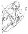
- FIG. 3is a partial side cross-sectional view of another embodiment of a handheld power sprayer having an air flow valve assembly in accordance with the present disclosure.
- FIG. 4is an elevation view of a power sprayer in accordance with the present disclosure mounted on a reservoir adapted to contain a fluid.
- FIG. 5is an elevation view of a power sprayer in accordance with the present disclosure and a reservoir adapted to contain a fluid, wherein the sprayer is not mounted on the reservoir.
- the present disclosurerelates to novel and advantageous flow controls, valves, and devices for controlling, starting, and stopping a flow, and to methods of making and using such controls, valves, and devices. More particularly, the present disclosure relates to controls, valves, and devices that control, start, and/or stop a flow in one direction and, more particularly, to one-way valves having an actuator assist.
- the present disclosurefurther relates to novel and advantageous dispensing or spray systems, sprayers, power sprayers, handheld sprayers, water guns or other toys, paint sprayers, or the like that include means for returning fluid or air to a reservoir of the device.
- a dispensing devicefor example, may include a return air valve that may be actuated by the vacuum created in the reservoir.
- the return air valvemay include an actuator, such as a lever, tab, etc., that may be used to initiate the opening of the valve, after which the vacuum created in the reservoir may then open the valve and maintain the valve in an open position until the vacuum is minimized or eliminated.
- a dispensing device of the present disclosuremay further include means for returning air to a reservoir during the removal of fluid from the reservoir or shortly after removal of fluid from the reservoir, such that the air pressure inside the reservoir returns to substantially the ambient air pressure.
- a valve 10or similar device for controlling, starting, and stopping a flow may be or comprise an umbrella-type valve or butterfly-type valve.
- the valve 10may be a unidirectional, or one-way valve, thereby allowing fluid or air flow in a single direction.
- the valve 10may be adapted to be coupled, operably coupled, or otherwise connected to a system having an air or fluid reservoir.
- the valve 10may comprise an umbrella membrane or disc 12 , a spring or spring-like structure 14 , an intake end 16 , and an exhaust end 18 .
- the umbrella disc 12may be generally thin, flat and circular in shape.
- the material from which the umbrella disc 12 may be manufacturedcan vary depending on the use of the valve 10 , dispensing device or system in which the valve 10 is used, and/or fluid that is provided in a reservoir of the dispensing device or system.
- the umbrella disc 12may be manufactured from any suitable material, including but not limited to, rubber, plastic or other suitable polymer, etc.
- the umbrella disc 12may have a normally closed position, wherein the umbrella disc 12 substantially forms a seal against disc seat 20 , thereby preventing air to flow from the intake end 16 to the exhaust end 18 .
- the spring 14may provide a bias to the umbrella disc 12 towards a closed position.
- the valve 10may further include a support structure 22 between the spring 14 and the umbrella disc 12 .
- the support structure 22may prevent direct contact between the spring 14 and the umbrella disc 12 , thereby preventing damage to the umbrella disc 12 that may be caused by direct contact with the spring 14 .
- the valve 10may be used as an air return valve.
- the intake end 16may comprise one or more slots or openings 24 for allowing air to enter the valve 10 .
- the exhaust end 18may be directly or operably coupled to a reservoir or other source of vacuum pressure.
- the vacuum created at the exhaust end 18may cause the valve 10 to open. That is, a vacuum created at the exhaust end 18 may cause the umbrella disc 12 to overcome the bias of the spring 14 and support structure 22 and become unseated from the disc seat 20 .
- the umbrella disc 12may open, allowing air flow from the intake end 16 to the exhaust end 18 , and, in some embodiments, into a reservoir.
- the umbrella disc 12 and valve 10may be configured such that minimal vacuum pressure at the exhaust end 18 can open the umbrella disc 12 or unseat the umbrella disc 12 from the disc seat 20 .
- the umbrella disc 12may also be configured to be strong enough so that, in the closed or seated position, leaks of fluid from the reservoir are not allowed through the valve 10 .
- the bias of the spring 14 and support structure 22may overcome the vacuum created at the exhaust end 18 and the umbrella disc 12 may become reseated on the disc seat 20 , thereby preventing air flow from the intake end 16 to the exhaust end 18 .
- fluid in the reservoirmay include air fresheners, insecticides, soap scum remover, tile grout cleaner, window cleaner, all purpose cleaner, etc. Therefore, in some cases, the fluid may comprise an aggressive formula that may leave a sticky residue on the umbrella disc 12 , thereby causing valve failure or inconsistency in valve operation, etc. and preventing correct air flow into the reservoir.
- the sticky residuemay cause the umbrella disc 12 to stick in an open position and allow leaks and/or stick in a closed position such that fluid or air is prevented from passing through.
- the sticky residuemay be caused, for example, by direct contact between the umbrella disc 12 and fluid from the reservoir that has seeped up into the valve 10 or by contact with vapors from the fluid in the reservoir.
- the valve 10may further include a mechanical actuator, such as a mechanical tab, rod, or lever, etc., that may open or initiate the opening of the valve 10 .
- a mechanical actuatorsuch as a mechanical tab, rod, or lever, etc.
- the mechanical actuatormay be a push rod 26 generally near the intake end 16 .
- the push rod 26may have a normal position with one end protruding from the intake end 16 of the valve 10 .
- the push rod 26may be activated by a trigger of the dispensing device or system.
- the triggermay abut the protruding end of the push rod 26 and cause the opposite end of the push rod to contact the umbrella disc 12 .
- Contact between the push rod 26 and the umbrella disc 12may unseat, or initiate the unseating of, the umbrella disc 12 from the disc seat 20 .
- the triggermay also actuate flow of air or fluid from a reservoir, the resulting vacuum created in the reservoir may cause the umbrella disc 12 to remain unseated or continue to become unseated from the disc seat 20 , thereby opening the valve 10 .
- the vacuum at the exhaust end 18may be created independently from the mechanism used to actuate the push rod 26 .
- the push rod 26may be activated by a component other than a trigger, such as but not limited to, a switch, a gear box assembly, etc.
- the push rod 26may be activated by any suitable mechanism in the dispensing device or system, such as any cam or lever assembly from a pump, gear box, motor assembly, etc. of the dispensing device or system.
- the mechanical actuatordoes not open the valve 10 enough to sufficiently allow air or fluid to flow from the intake end 16 to the exhaust end 18 . Rather, the mechanical actuator initiates the opening while the vacuum created in the reservoir may provide the force to sufficiently open the umbrella disc 12 . Once the pressure in the reservoir reaches substantially ambient pressure, the bias of the spring 14 and support structure 22 may overcome the vacuum created by the reservoir and the umbrella disc 12 may become reseated on the disc seat 20 , thereby preventing flow from the intake end 16 to the exhaust end 18 . In alternative embodiments, the mechanical actuator opens the valve 10 enough to sufficiently allow air or fluid to flow from the intake end 16 to the exhaust end 18 , and the vacuum created in the reservoir may provide the force to maintain the valve 10 in an open position.
- the mechanical actuatormay be used to unseat the umbrella disc 12 to any suitable extent, such that the vacuum created in the reservoir can maintain the umbrella disc 12 in an open position or continue to open the umbrella disc 12 to a fully opened position.
- mechanical actuators other than a push rodmay be used, such as a tab or mechanical slider, etc.
- an air return valve 30may be used to allow air to return to a reservoir 32 of a dispensing device or system 28 , such as, but not limited to, a sprayer.
- the air return valve 30may be a one-way valve that allows air flow in one direction while preventing air flow or fluid flow in the opposite direction.
- the air return valve 30may only allow air flow towards and into the reservoir 32 , but may not allow air flow out of the reservoir 32 .
- the air return valve 30may be directly or operably coupled to the reservoir 32 . As such, air may flow through the air return valve 30 and into the reservoir 32 .
- the air return valve 30may allow air to flow into the reservoir 32 when the seal of the air return valve is released or open.
- the seal in the air return valve 30may be released or opened by the vacuum pressure created in the reservoir 32 when fluid is pulled from, and out of, the reservoir 32 .
- the air return valve 30may open and allow air to flow into the reservoir 32 during the removal of fluid from the reservoir 32 or shortly after removal of fluid from the reservoir 32 .
- the air return valve 30may allow air to flow into the reservoir 32 , upon, during, and/or shortly after actuation of the dispensing device 28 by, for example, a trigger 34 .
- the push rod 26 of the air return valve 30may be activated by the trigger 34 .
- the trigger 34may have a tab, lever, contact point, or the like 36 that may abut and/or push on push rod 26 when the trigger 34 is activated.
- the trigger 34need not include tab 36 , but may be shaped or configured in any other suitable manner such that the trigger 34 activates push rod 26 .
- the triggermay include another tab, lever, contact point, or the like 38 that, upon activation of the trigger 34 , may abut and/or contact an isolated battery compartment, further discussed below, to complete an electrical circuit and activate a dispensing device 28 .
- the trigger 34need not include tab 38 , but may be shaped or configured in any other suitable manner such that the trigger 34 completes an electrical circuit to activate the dispensing device 28 .
- the tabs 36 and 38are configured so that upon activation of the trigger 34 , the tab 36 and tab 38 generally simultaneously, and respectively, activate the push rod 26 and the dispensing device 28 .
- a dispensing device of the present disclosuremay include some or all of the components, features, and advantages of a power sprayer as disclosed in U.S. patent application Ser. No. 11/693,426, filed Mar. 29, 2007, entitled Power Sprayer, and published on Oct. 4, 2007 under U.S. Publication No. 2007/0228186, the entirety of which is hereby incorporated by reference herein.
- a dispensing device 40may include a spray head 42 , a cap 44 , and a flexible intake tube 46 .
- the spray head 42 and cap 44may be located outside the reservoir 48
- the flexible intake tube 46may be located inside the reservoir 48 .
- the spray head 42may include a housing 50 , a nozzle cap 52 , a trigger 54 , and a safety lock 56 .
- the cap 44may connect the spray head 42 to the reservoir 48 via female threads adapted to mate with the male threads of the neck 58 .
- the cap 44may be adapted to be compatible with most reservoirs 48 used to hold common household, garage, and garden liquids.
- the trigger 54is used to actuate the sprayer dispensing device 40 . As indicated in FIGS. 4 and 5 , in one embodiment, the dispensing device 40 may be actuated by partially displacing the trigger 54 into the housing 50 .
- a battery tube 60may extend from the cap 44 down into the reservoir 48 .
- an isolated or separate battery compartment 62may be contained within the sprayer housing 50 , to the rear of the housing, and spaced away from and generally downwardly from the pump and motor.
- the dispensing devicemay include a reciprocating piston-type pump, dual reciprocating pump, a gear pump, a peristaltic pump, or other suitable pumping assembly without departing from the spirit and scope of the invention.
- the spray head 42may be operably coupled to, but remote from, separate, or not directly connected to the reservoir 48 of material to be dispensed.
- any embodiment of the spray head 42 in accordance with the present inventioncould be disposable.
- the air valve of the present disclosureis not limited to use with power sprayers and may be used in a variety of applications including, but not limited to, refining or chemical processing industries, coating systems or mechanisms, handheld sprayers, water guns or other toys, paint sprayers, or any other environment where relief of a vacuum pressure is desired, including the return of air into a container having a fluid, where dispensing the fluid creates a vacuum.
- the air return valvemay be oriented generally vertically, diagonally, or at any other suitable angle without departing from the spirit and scope of the present disclosure.
Landscapes
- Containers And Packaging Bodies Having A Special Means To Remove Contents (AREA)
- Check Valves (AREA)
- Fluid-Driven Valves (AREA)
- Catching Or Destruction (AREA)
Abstract
Description
Claims (14)
Priority Applications (9)
| Application Number | Priority Date | Filing Date | Title |
|---|---|---|---|
| US11/963,282US8602386B2 (en) | 2007-12-21 | 2007-12-21 | Valve with actuator assist |
| US12/188,960US7648083B2 (en) | 2003-12-18 | 2008-08-08 | Power sprayer |
| MX2010006981AMX2010006981A (en) | 2007-12-21 | 2008-12-18 | Valve with actuator assist. |
| AU2008343922AAU2008343922B2 (en) | 2007-12-21 | 2008-12-18 | Valve with actuator assist |
| JP2010539478AJP5615182B2 (en) | 2007-12-21 | 2008-12-18 | Actuator auxiliary valve |
| PCT/US2008/013825WO2009085175A1 (en) | 2007-12-21 | 2008-12-18 | Valve with actuator assist |
| CN200880127177.0ACN101945709B (en) | 2007-12-21 | 2008-12-18 | Valve with actuator assist |
| EP08867765AEP2237895A1 (en) | 2007-12-21 | 2008-12-18 | Valve with actuator assist |
| CA2710353ACA2710353C (en) | 2007-12-21 | 2008-12-18 | Valve with actuator assist |
Applications Claiming Priority (1)
| Application Number | Priority Date | Filing Date | Title |
|---|---|---|---|
| US11/963,282US8602386B2 (en) | 2007-12-21 | 2007-12-21 | Valve with actuator assist |
Related Child Applications (1)
| Application Number | Title | Priority Date | Filing Date |
|---|---|---|---|
| US11/693,426Continuation-In-PartUS7568637B2 (en) | 2003-12-18 | 2007-03-29 | Power sprayer |
Publications (2)
| Publication Number | Publication Date |
|---|---|
| US20090159723A1 US20090159723A1 (en) | 2009-06-25 |
| US8602386B2true US8602386B2 (en) | 2013-12-10 |
Family
ID=40418927
Family Applications (1)
| Application Number | Title | Priority Date | Filing Date |
|---|---|---|---|
| US11/963,282Active2030-02-03US8602386B2 (en) | 2003-12-18 | 2007-12-21 | Valve with actuator assist |
Country Status (8)
| Country | Link |
|---|---|
| US (1) | US8602386B2 (en) |
| EP (1) | EP2237895A1 (en) |
| JP (1) | JP5615182B2 (en) |
| CN (1) | CN101945709B (en) |
| AU (1) | AU2008343922B2 (en) |
| CA (1) | CA2710353C (en) |
| MX (1) | MX2010006981A (en) |
| WO (1) | WO2009085175A1 (en) |
Cited By (2)
| Publication number | Priority date | Publication date | Assignee | Title |
|---|---|---|---|---|
| WO2018022621A1 (en) | 2016-07-25 | 2018-02-01 | Kinnos Inc. | Device and related compositions and methods for use in surface decontamination |
| WO2020014612A1 (en) | 2018-07-12 | 2020-01-16 | Kinnos Inc. | Devices, compositions, and methods for use in surface decontamination |
Families Citing this family (13)
| Publication number | Priority date | Publication date | Assignee | Title |
|---|---|---|---|---|
| US7648083B2 (en)* | 2003-12-18 | 2010-01-19 | S.C. Johnson & Son, Inc. | Power sprayer |
| USD628898S1 (en) | 2010-02-19 | 2010-12-14 | Medtech Products, Inc. | Spray nozzle |
| USD628899S1 (en) | 2010-02-19 | 2010-12-14 | Medtech Products, Inc. | Spray nozzle |
| USD628900S1 (en) | 2010-02-19 | 2010-12-14 | Medtech Products, Inc. | Spray nozzle |
| USD628901S1 (en) | 2010-02-19 | 2010-12-14 | Medtech Products, Inc. | Spray nozzle |
| USD652299S1 (en) | 2010-06-01 | 2012-01-17 | Magic Tap, LLC | Fluid pump |
| DK2729259T3 (en)* | 2011-07-06 | 2016-04-04 | Gea Process Engineering As | Pop up nozzle, cleaning unit and operating procedure |
| CN105228757A (en) | 2013-03-15 | 2016-01-06 | 埃莫实验室公司 | There is the sonic transducer of bending limiting part |
| USD741835S1 (en) | 2013-12-27 | 2015-10-27 | Emo Labs, Inc. | Speaker |
| USD733678S1 (en) | 2013-12-27 | 2015-07-07 | Emo Labs, Inc. | Audio speaker |
| RU2017107258A (en)* | 2014-09-22 | 2018-10-24 | Эбботт Хэлскеа Пвт. Лтд. | DEVICE FOR PROVIDING THE DOSED FEED OF A VISCOUS MATTER AND A DISPENSER CONTAINING THIS DEVICE |
| GB201614355D0 (en)* | 2016-08-23 | 2016-10-05 | Siemens Healthcare Ltd | Valve for closure of an opening into a cryogen vessel |
| CN110383355B (en)* | 2017-03-07 | 2021-08-27 | 埃科莱布美国股份有限公司 | Monitoring module for hand hygiene dispenser |
Citations (89)
| Publication number | Priority date | Publication date | Assignee | Title |
|---|---|---|---|---|
| US2117747A (en) | 1936-06-26 | 1938-05-17 | Smith Herman | Milk-dispensing device |
| US2704690A (en) | 1952-08-01 | 1955-03-22 | Eichenauer Rudolf | Spray gun |
| US3137326A (en) | 1960-09-15 | 1964-06-16 | Welty Frank | Method and apparatus for dispensing carbonated beverages from bulk containers |
| US3445068A (en) | 1965-12-17 | 1969-05-20 | Josef Wagner | Liquid atomizer |
| US3490656A (en) | 1968-05-21 | 1970-01-20 | Kenneth A Taschner | Compressed gas-type liquid dispenser |
| US3667655A (en) | 1970-03-30 | 1972-06-06 | Dow Chemical Co | Method for the rapid assembly of diptubes into spray cans and a diptube useful therein |
| US3904116A (en) | 1975-01-09 | 1975-09-09 | Disston Inc | Portable cordless sprayer |
| US3967765A (en) | 1972-08-09 | 1976-07-06 | Leeds And Micallef | Multiple purpose nozzle |
| US3993250A (en) | 1975-05-19 | 1976-11-23 | Shure Alan H | Apparatus for spraying liquid materials |
| US3998736A (en)* | 1976-05-12 | 1976-12-21 | Greenleaf Jr John W | Sewage disposal system |
| US4020979A (en) | 1975-10-15 | 1977-05-03 | Summit Packaging Systems, Inc. | Squeeze-bottle-type spray dispenser |
| US4153203A (en) | 1977-03-02 | 1979-05-08 | Tetsuya Tada | Trigger type sprayer |
| US4154375A (en) | 1977-09-28 | 1979-05-15 | Rockwell International Corporation | Personal care sprayer |
| US4162037A (en) | 1977-05-20 | 1979-07-24 | Masaya Koyama | Automatic sprayer |
| JPS54117608A (en) | 1978-03-06 | 1979-09-12 | Nippon Telegr & Teleph Corp <Ntt> | Double balanced mixer |
| US4182465A (en) | 1978-06-12 | 1980-01-08 | Bennett Robert A | Manually operated pump using hollow flexible member as pumping chamber |
| US4182496A (en) | 1977-12-16 | 1980-01-08 | Ethyl Products Company | Actuator button for fluid dispenser |
| US4187959A (en) | 1978-08-17 | 1980-02-12 | The Continental Group, Inc. | Propellantless aerosol dispensing system |
| US4189098A (en) | 1978-03-23 | 1980-02-19 | Spray Tech Corporation | Household spray apparatus |
| US4204614A (en) | 1978-09-28 | 1980-05-27 | Diamond International Corporation | Fluid dispenser having a spring biased locking mechanism for a safety nozzle cap |
| US4234128A (en) | 1978-02-06 | 1980-11-18 | The Afa Corporation | Nozzle assembly |
| US4239129A (en) | 1978-11-29 | 1980-12-16 | Esposito Gary F | Water pistol and/or flashlight structure |
| US4260079A (en) | 1978-01-25 | 1981-04-07 | The Afa Corporation | Manually operated liquid dispensers |
| US4273290A (en) | 1977-11-14 | 1981-06-16 | The Afa Corporation | Unitary valve and spring assembly |
| US4393993A (en) | 1980-05-30 | 1983-07-19 | J. Wagner Gmbh | Spray gun |
| US4516695A (en) | 1981-02-09 | 1985-05-14 | The Afa Corporation | Child-resistant liquid dispenser sprayer or like apparatus |
| US4618099A (en) | 1984-07-13 | 1986-10-21 | Kyushu Hitachi Maxell, Ltd. | Electric spray |
| US4621770A (en) | 1981-12-14 | 1986-11-11 | Sayen Michael D | Plant watering/misting device |
| US4706888A (en) | 1986-07-11 | 1987-11-17 | Calmar, Inc. | Multi-purpose nozzle assembly |
| US4767033A (en) | 1986-07-31 | 1988-08-30 | The Drackett Company | Manually operated gear pump spray head |
| US4830235A (en) | 1988-02-01 | 1989-05-16 | Miller Michael D | Siphon tube apparatus |
| US4881687A (en) | 1987-06-29 | 1989-11-21 | Tecnoma | Portable liquid sprayer, particularly for the treatment of plants |
| US4925105A (en) | 1989-04-14 | 1990-05-15 | Lin Hsien C | Rechargeable garden sprayer |
| US5014884A (en) | 1988-10-25 | 1991-05-14 | Erich Wunsch | Spray container |
| US5069365A (en) | 1989-05-31 | 1991-12-03 | Woodhouse Robert C | Chemical dispensing system |
| US5078188A (en) | 1987-03-04 | 1992-01-07 | Helix, Enterprises, Inc. | Flow rate limiting device for an automatic shut-off liquid dispensing nozzle |
| US5147292A (en) | 1991-02-05 | 1992-09-15 | C. R. Bard, Inc. | Control handle with locking means for surgical irrigation |
| US5150841A (en) | 1989-09-11 | 1992-09-29 | Dowbrands Inc. | Liquid spray dispenser |
| US5154317A (en) | 1990-07-09 | 1992-10-13 | Roppolo Iii Michael A | Portable liquid dispenser |
| US5156304A (en) | 1990-03-27 | 1992-10-20 | Guala S.P.A. | Trigger-type device for a sprayer pump for use on handheld containers |
| US5184756A (en) | 1991-07-18 | 1993-02-09 | Talk To Me Products, Inc. | Flywheel water gun |
| US5195664A (en) | 1992-04-03 | 1993-03-23 | Steven Rhea | All directional fluid pick-up |
| US5215227A (en) | 1992-07-10 | 1993-06-01 | Farner Norbert A | Assailant marker |
| EP0593900A2 (en) | 1992-09-23 | 1994-04-27 | Eckart Dipl.-Ing. Wunsch | Device for micro-spraying liquids |
| US5360153A (en) | 1993-05-13 | 1994-11-01 | Avery Dennison Corporation | Electric powered apparatus for dispensing individual plastic fasteners from fastener stock |
| US5364111A (en) | 1991-04-03 | 1994-11-15 | Eckart Wunsch | Sealing arrangement |
| US5427274A (en) | 1992-07-23 | 1995-06-27 | Wood; Robert | Product delivery system for delivering sterile liquid product |
| US5499766A (en) | 1991-12-13 | 1996-03-19 | Contico International, Inc. | Nozzle assembly for trigger sprayer |
| WO1996018572A1 (en) | 1994-12-12 | 1996-06-20 | Contico International, Inc. | Pressure buildup trigger sprayer |
| US5549249A (en) | 1991-12-13 | 1996-08-27 | Contico International, Inc. | Fluid spinner and nozzle head assembly with controlled fluid flood path |
| US5590837A (en) | 1995-02-28 | 1997-01-07 | Calmar Inc. | Sprayer having variable spray pattern |
| US5605496A (en) | 1995-05-02 | 1997-02-25 | The Pickard's Trust | Abrasive blasting gun |
| US5657907A (en) | 1995-11-13 | 1997-08-19 | Calmar Inc. | Orifice cover slide for trigger sprayer |
| US5716007A (en) | 1995-12-29 | 1998-02-10 | Nottingham-Spirk Design Associates, Inc. | Battery operated fluid dispenser |
| US5769325A (en)* | 1993-05-28 | 1998-06-23 | Valois S.A. | Spray nozzle and a sprayer including such a nozzle |
| US5878925A (en) | 1997-06-17 | 1999-03-09 | Apla-Tech, Inc. | Drywall joint compound pump workstation |
| US5964377A (en)* | 1997-10-14 | 1999-10-12 | S. C. Johnson & Son, Inc. | Manually operable pump for mixing and dispensing primary and secondary fluids |
| US6022473A (en) | 1998-07-06 | 2000-02-08 | Mickelson; Doug | Oil changing system |
| USD423934S (en) | 1999-08-09 | 2000-05-02 | Owens-Illinois Closure Inc. | Shroud for a pump dispenser |
| EP1013345A2 (en) | 1998-12-15 | 2000-06-28 | Calmar Inc. | Trigger actuated pump sprayer |
| US6227412B1 (en) | 2000-03-03 | 2001-05-08 | Saint-Gobain Calmar Inc. | Dip tube filter for manually actuated dispenser |
| USD442088S1 (en) | 2000-02-16 | 2001-05-15 | Owens-Illinois Closure Inc. | Trigger pump dispenser shroud |
| US6260722B1 (en) | 1999-12-29 | 2001-07-17 | Phoenix Closures, Inc. | Cap and container assembly |
| USD454778S1 (en) | 2000-06-26 | 2002-03-26 | The Procter & Gamble Company | Sprayer head |
| US6478196B2 (en) | 1997-12-18 | 2002-11-12 | Ing. Erich Pfeiffer Gmbh | Media dispenser |
| US6502766B1 (en) | 2000-07-24 | 2003-01-07 | The Procter & Gamble Company | Liquid sprayers |
| US20030062503A1 (en)* | 2000-03-09 | 2003-04-03 | Nl Technologies, Ltd. | Sanitary drain valve design |
| US6554211B1 (en) | 2002-08-01 | 2003-04-29 | Saint-Gobain Calmar Inc. | Container vent control for battery operated sprayer |
| US6595437B1 (en) | 1998-04-08 | 2003-07-22 | The Procter & Gamble Company | Packaged product |
| US6752330B2 (en)* | 2000-07-24 | 2004-06-22 | The Procter & Gamble Company | Liquid sprayers |
| USD494866S1 (en) | 2003-06-23 | 2004-08-24 | Stefano Guala | Spraying head |
| US6796515B2 (en)* | 2001-06-04 | 2004-09-28 | L. R. Nelson Corporation | One touch actuated valve |
| US20050082389A1 (en) | 2003-10-07 | 2005-04-21 | Sanchez Michael J. | Methods and apparatus for battery powered hand-held sprayer with remote spray gun assembly |
| US20050098577A1 (en) | 2003-04-30 | 2005-05-12 | Huy Gerhart P. | Hand-crankable water guns |
| EP1543884A2 (en) | 2003-12-18 | 2005-06-22 | Cepia, LLC | Motor Driven Spray Device |
| US20050133624A1 (en) | 2003-12-18 | 2005-06-23 | Hornsby James R. | Power sprayer |
| US20050133627A1 (en) | 2003-12-18 | 2005-06-23 | Hornsby James R. | Power sprayer |
| US6910605B2 (en)* | 2001-03-10 | 2005-06-28 | Alfred Von Schuckmann | Pump which can be actuated by a hand lever |
| US20050189381A1 (en) | 2002-04-30 | 2005-09-01 | Yoshino Kogyosho Co., Ltd. | Trigger type fluid ejector |
| US20050194467A1 (en) | 2004-03-03 | 2005-09-08 | Saint-Gobain Calmar Inc. | Dischage/vent module for power sprayer |
| US6945438B1 (en) | 2005-01-26 | 2005-09-20 | Chun-Chia Shih | Pesticide spraying cart |
| US7011521B2 (en) | 2002-03-22 | 2006-03-14 | Ferton Holding S.A. | Dental handpiece |
| US7021399B2 (en) | 2000-03-10 | 2006-04-04 | Black & Decker Inc. | Power tool |
| WO2006101730A2 (en) | 2005-03-17 | 2006-09-28 | Saint-Gobain Calmar, Inc. | Compact battery operated spray head fittable onto existing pump spray containers and providing improved balance |
| US20070090321A1 (en)* | 2005-10-26 | 2007-04-26 | Toralf Bork | Dynamic hermetic barrier for use with implantable infusion pumps |
| US7246755B2 (en) | 2003-12-18 | 2007-07-24 | Cepia, Llc | Power sprayer |
| US7328859B2 (en) | 2003-12-18 | 2008-02-12 | Cepia, Llc | Power sprayer |
| US20090032618A1 (en) | 2003-12-18 | 2009-02-05 | James Russell Hornsby | Power sprayer |
| US20090152486A1 (en)* | 2007-12-14 | 2009-06-18 | Hyundai Motor Company | Pressure adjusting valve for vehicle fuel line |
Family Cites Families (6)
| Publication number | Priority date | Publication date | Assignee | Title |
|---|---|---|---|---|
| IT1063280B (en)* | 1976-05-12 | 1985-02-11 | Sits Soc It Telecom Siemens | ELECTRONIC PROCESSOR ORIENTED TO TELEPHONE TRAFFIC MANAGEMENT |
| NL8420310A (en)* | 1983-12-14 | 1985-11-01 | Schotte Werner | Atomising pump with attached fluid container |
| US5779108A (en)* | 1995-06-15 | 1998-07-14 | Calmar Inc. | Pressure venting trigger sprayer |
| CN2261902Y (en)* | 1996-03-04 | 1997-09-10 | 杨玉富 | Sliding water gap valve for steel ladle |
| JPH10286499A (en)* | 1997-04-16 | 1998-10-27 | Kao Corp | Spray container |
| CN2395810Y (en)* | 1999-09-07 | 2000-09-13 | 李�杰 | Pneumatic adhesive gun |
- 2007
- 2007-12-21USUS11/963,282patent/US8602386B2/enactiveActive
- 2008
- 2008-12-18AUAU2008343922Apatent/AU2008343922B2/enactiveActive
- 2008-12-18JPJP2010539478Apatent/JP5615182B2/enactiveActive
- 2008-12-18WOPCT/US2008/013825patent/WO2009085175A1/enactiveApplication Filing
- 2008-12-18MXMX2010006981Apatent/MX2010006981A/enactiveIP Right Grant
- 2008-12-18EPEP08867765Apatent/EP2237895A1/ennot_activeCeased
- 2008-12-18CACA2710353Apatent/CA2710353C/enactiveActive
- 2008-12-18CNCN200880127177.0Apatent/CN101945709B/enactiveActive
Patent Citations (96)
| Publication number | Priority date | Publication date | Assignee | Title |
|---|---|---|---|---|
| US2117747A (en) | 1936-06-26 | 1938-05-17 | Smith Herman | Milk-dispensing device |
| US2704690A (en) | 1952-08-01 | 1955-03-22 | Eichenauer Rudolf | Spray gun |
| US3137326A (en) | 1960-09-15 | 1964-06-16 | Welty Frank | Method and apparatus for dispensing carbonated beverages from bulk containers |
| US3445068A (en) | 1965-12-17 | 1969-05-20 | Josef Wagner | Liquid atomizer |
| US3490656A (en) | 1968-05-21 | 1970-01-20 | Kenneth A Taschner | Compressed gas-type liquid dispenser |
| US3667655A (en) | 1970-03-30 | 1972-06-06 | Dow Chemical Co | Method for the rapid assembly of diptubes into spray cans and a diptube useful therein |
| US3967765A (en) | 1972-08-09 | 1976-07-06 | Leeds And Micallef | Multiple purpose nozzle |
| US3904116A (en) | 1975-01-09 | 1975-09-09 | Disston Inc | Portable cordless sprayer |
| US3993250A (en) | 1975-05-19 | 1976-11-23 | Shure Alan H | Apparatus for spraying liquid materials |
| US4020979A (en) | 1975-10-15 | 1977-05-03 | Summit Packaging Systems, Inc. | Squeeze-bottle-type spray dispenser |
| US3998736A (en)* | 1976-05-12 | 1976-12-21 | Greenleaf Jr John W | Sewage disposal system |
| US4153203A (en) | 1977-03-02 | 1979-05-08 | Tetsuya Tada | Trigger type sprayer |
| US4162037A (en) | 1977-05-20 | 1979-07-24 | Masaya Koyama | Automatic sprayer |
| US4154375A (en) | 1977-09-28 | 1979-05-15 | Rockwell International Corporation | Personal care sprayer |
| US4273290A (en) | 1977-11-14 | 1981-06-16 | The Afa Corporation | Unitary valve and spring assembly |
| US4182496A (en) | 1977-12-16 | 1980-01-08 | Ethyl Products Company | Actuator button for fluid dispenser |
| US4260079A (en) | 1978-01-25 | 1981-04-07 | The Afa Corporation | Manually operated liquid dispensers |
| US4234128A (en) | 1978-02-06 | 1980-11-18 | The Afa Corporation | Nozzle assembly |
| JPS54117608A (en) | 1978-03-06 | 1979-09-12 | Nippon Telegr & Teleph Corp <Ntt> | Double balanced mixer |
| US4189098A (en) | 1978-03-23 | 1980-02-19 | Spray Tech Corporation | Household spray apparatus |
| US4182465A (en) | 1978-06-12 | 1980-01-08 | Bennett Robert A | Manually operated pump using hollow flexible member as pumping chamber |
| US4187959A (en) | 1978-08-17 | 1980-02-12 | The Continental Group, Inc. | Propellantless aerosol dispensing system |
| US4204614A (en) | 1978-09-28 | 1980-05-27 | Diamond International Corporation | Fluid dispenser having a spring biased locking mechanism for a safety nozzle cap |
| US4239129A (en) | 1978-11-29 | 1980-12-16 | Esposito Gary F | Water pistol and/or flashlight structure |
| US4393993A (en) | 1980-05-30 | 1983-07-19 | J. Wagner Gmbh | Spray gun |
| US4516695A (en) | 1981-02-09 | 1985-05-14 | The Afa Corporation | Child-resistant liquid dispenser sprayer or like apparatus |
| US4621770A (en) | 1981-12-14 | 1986-11-11 | Sayen Michael D | Plant watering/misting device |
| US4618099A (en) | 1984-07-13 | 1986-10-21 | Kyushu Hitachi Maxell, Ltd. | Electric spray |
| US4706888A (en) | 1986-07-11 | 1987-11-17 | Calmar, Inc. | Multi-purpose nozzle assembly |
| US4767033A (en) | 1986-07-31 | 1988-08-30 | The Drackett Company | Manually operated gear pump spray head |
| US5078188A (en) | 1987-03-04 | 1992-01-07 | Helix, Enterprises, Inc. | Flow rate limiting device for an automatic shut-off liquid dispensing nozzle |
| US4881687A (en) | 1987-06-29 | 1989-11-21 | Tecnoma | Portable liquid sprayer, particularly for the treatment of plants |
| US4830235A (en) | 1988-02-01 | 1989-05-16 | Miller Michael D | Siphon tube apparatus |
| US5014884A (en) | 1988-10-25 | 1991-05-14 | Erich Wunsch | Spray container |
| US4925105A (en) | 1989-04-14 | 1990-05-15 | Lin Hsien C | Rechargeable garden sprayer |
| US5069365A (en) | 1989-05-31 | 1991-12-03 | Woodhouse Robert C | Chemical dispensing system |
| US5150841A (en) | 1989-09-11 | 1992-09-29 | Dowbrands Inc. | Liquid spray dispenser |
| US5156304A (en) | 1990-03-27 | 1992-10-20 | Guala S.P.A. | Trigger-type device for a sprayer pump for use on handheld containers |
| US5154317A (en) | 1990-07-09 | 1992-10-13 | Roppolo Iii Michael A | Portable liquid dispenser |
| US5147292A (en) | 1991-02-05 | 1992-09-15 | C. R. Bard, Inc. | Control handle with locking means for surgical irrigation |
| US5364111A (en) | 1991-04-03 | 1994-11-15 | Eckart Wunsch | Sealing arrangement |
| US5184756A (en) | 1991-07-18 | 1993-02-09 | Talk To Me Products, Inc. | Flywheel water gun |
| US5549249A (en) | 1991-12-13 | 1996-08-27 | Contico International, Inc. | Fluid spinner and nozzle head assembly with controlled fluid flood path |
| US5499766A (en) | 1991-12-13 | 1996-03-19 | Contico International, Inc. | Nozzle assembly for trigger sprayer |
| US5195664A (en) | 1992-04-03 | 1993-03-23 | Steven Rhea | All directional fluid pick-up |
| US5215227A (en) | 1992-07-10 | 1993-06-01 | Farner Norbert A | Assailant marker |
| US5427274A (en) | 1992-07-23 | 1995-06-27 | Wood; Robert | Product delivery system for delivering sterile liquid product |
| EP0593900A2 (en) | 1992-09-23 | 1994-04-27 | Eckart Dipl.-Ing. Wunsch | Device for micro-spraying liquids |
| US5397034A (en) | 1992-09-23 | 1995-03-14 | Wunsch; Eckart | Finely atomizing device for fluids |
| US5360153A (en) | 1993-05-13 | 1994-11-01 | Avery Dennison Corporation | Electric powered apparatus for dispensing individual plastic fasteners from fastener stock |
| US5769325A (en)* | 1993-05-28 | 1998-06-23 | Valois S.A. | Spray nozzle and a sprayer including such a nozzle |
| WO1996018572A1 (en) | 1994-12-12 | 1996-06-20 | Contico International, Inc. | Pressure buildup trigger sprayer |
| US5590837A (en) | 1995-02-28 | 1997-01-07 | Calmar Inc. | Sprayer having variable spray pattern |
| US5605496A (en) | 1995-05-02 | 1997-02-25 | The Pickard's Trust | Abrasive blasting gun |
| US5657907A (en) | 1995-11-13 | 1997-08-19 | Calmar Inc. | Orifice cover slide for trigger sprayer |
| US5716007A (en) | 1995-12-29 | 1998-02-10 | Nottingham-Spirk Design Associates, Inc. | Battery operated fluid dispenser |
| US5878925A (en) | 1997-06-17 | 1999-03-09 | Apla-Tech, Inc. | Drywall joint compound pump workstation |
| US5964377A (en)* | 1997-10-14 | 1999-10-12 | S. C. Johnson & Son, Inc. | Manually operable pump for mixing and dispensing primary and secondary fluids |
| US6478196B2 (en) | 1997-12-18 | 2002-11-12 | Ing. Erich Pfeiffer Gmbh | Media dispenser |
| US6595437B1 (en) | 1998-04-08 | 2003-07-22 | The Procter & Gamble Company | Packaged product |
| US6022473A (en) | 1998-07-06 | 2000-02-08 | Mickelson; Doug | Oil changing system |
| EP1013345A2 (en) | 1998-12-15 | 2000-06-28 | Calmar Inc. | Trigger actuated pump sprayer |
| USD423934S (en) | 1999-08-09 | 2000-05-02 | Owens-Illinois Closure Inc. | Shroud for a pump dispenser |
| US6260722B1 (en) | 1999-12-29 | 2001-07-17 | Phoenix Closures, Inc. | Cap and container assembly |
| USD442088S1 (en) | 2000-02-16 | 2001-05-15 | Owens-Illinois Closure Inc. | Trigger pump dispenser shroud |
| US6227412B1 (en) | 2000-03-03 | 2001-05-08 | Saint-Gobain Calmar Inc. | Dip tube filter for manually actuated dispenser |
| US20030062503A1 (en)* | 2000-03-09 | 2003-04-03 | Nl Technologies, Ltd. | Sanitary drain valve design |
| US7021399B2 (en) | 2000-03-10 | 2006-04-04 | Black & Decker Inc. | Power tool |
| USD454778S1 (en) | 2000-06-26 | 2002-03-26 | The Procter & Gamble Company | Sprayer head |
| USD454779S1 (en) | 2000-06-26 | 2002-03-26 | The Procter & Gamble Company | Liquid spray container |
| US6502766B1 (en) | 2000-07-24 | 2003-01-07 | The Procter & Gamble Company | Liquid sprayers |
| US6752330B2 (en)* | 2000-07-24 | 2004-06-22 | The Procter & Gamble Company | Liquid sprayers |
| US20030052194A1 (en) | 2000-07-24 | 2003-03-20 | Streutker Alen David | Venting mechanism |
| US6910605B2 (en)* | 2001-03-10 | 2005-06-28 | Alfred Von Schuckmann | Pump which can be actuated by a hand lever |
| US6796515B2 (en)* | 2001-06-04 | 2004-09-28 | L. R. Nelson Corporation | One touch actuated valve |
| US7011521B2 (en) | 2002-03-22 | 2006-03-14 | Ferton Holding S.A. | Dental handpiece |
| US20050189381A1 (en) | 2002-04-30 | 2005-09-01 | Yoshino Kogyosho Co., Ltd. | Trigger type fluid ejector |
| US6554211B1 (en) | 2002-08-01 | 2003-04-29 | Saint-Gobain Calmar Inc. | Container vent control for battery operated sprayer |
| US20050098577A1 (en) | 2003-04-30 | 2005-05-12 | Huy Gerhart P. | Hand-crankable water guns |
| USD495399S1 (en) | 2003-06-23 | 2004-08-31 | Guala Dispensing S.P.A. | Spraying head |
| USD494866S1 (en) | 2003-06-23 | 2004-08-24 | Stefano Guala | Spraying head |
| US20050082389A1 (en) | 2003-10-07 | 2005-04-21 | Sanchez Michael J. | Methods and apparatus for battery powered hand-held sprayer with remote spray gun assembly |
| WO2005060685A2 (en) | 2003-12-18 | 2005-07-07 | Cepia, Llc | Power sprayer |
| US20070228186A1 (en) | 2003-12-18 | 2007-10-04 | Cepia, Llc | Power sprayer |
| US20090032618A1 (en) | 2003-12-18 | 2009-02-05 | James Russell Hornsby | Power sprayer |
| US7328859B2 (en) | 2003-12-18 | 2008-02-12 | Cepia, Llc | Power sprayer |
| US20050133624A1 (en) | 2003-12-18 | 2005-06-23 | Hornsby James R. | Power sprayer |
| EP1543884A2 (en) | 2003-12-18 | 2005-06-22 | Cepia, LLC | Motor Driven Spray Device |
| US7097119B2 (en) | 2003-12-18 | 2006-08-29 | Cepia, Llc | Power sprayer |
| US20050133627A1 (en) | 2003-12-18 | 2005-06-23 | Hornsby James R. | Power sprayer |
| US7246755B2 (en) | 2003-12-18 | 2007-07-24 | Cepia, Llc | Power sprayer |
| US20050194467A1 (en) | 2004-03-03 | 2005-09-08 | Saint-Gobain Calmar Inc. | Dischage/vent module for power sprayer |
| US6945438B1 (en) | 2005-01-26 | 2005-09-20 | Chun-Chia Shih | Pesticide spraying cart |
| WO2006101730A2 (en) | 2005-03-17 | 2006-09-28 | Saint-Gobain Calmar, Inc. | Compact battery operated spray head fittable onto existing pump spray containers and providing improved balance |
| US20070090321A1 (en)* | 2005-10-26 | 2007-04-26 | Toralf Bork | Dynamic hermetic barrier for use with implantable infusion pumps |
| US20090152486A1 (en)* | 2007-12-14 | 2009-06-18 | Hyundai Motor Company | Pressure adjusting valve for vehicle fuel line |
Non-Patent Citations (5)
| Title |
|---|
| English Translation of JP 54-117608, document date Aug. 17, 1979. |
| http://www.solousa.com, 3 pages, Nov. 2004, "Chemical Applicators: Backpack Sprayers". |
| http://www.solousa.com. 1 page, Nov. 2004. "Chemical Applicators: Handheld Sprayers". |
| PCT/US2008/013825 International Search Report and Written Opinion dated Mar. 24, 2009. |
| Saint-Gobain Calmar Inc., Copyright 2004, "PS2003 Ready to Use Power Sprayer", 2 pages. |
Cited By (2)
| Publication number | Priority date | Publication date | Assignee | Title |
|---|---|---|---|---|
| WO2018022621A1 (en) | 2016-07-25 | 2018-02-01 | Kinnos Inc. | Device and related compositions and methods for use in surface decontamination |
| WO2020014612A1 (en) | 2018-07-12 | 2020-01-16 | Kinnos Inc. | Devices, compositions, and methods for use in surface decontamination |
Also Published As
| Publication number | Publication date |
|---|---|
| CA2710353A1 (en) | 2009-07-09 |
| WO2009085175A1 (en) | 2009-07-09 |
| JP2011507769A (en) | 2011-03-10 |
| EP2237895A1 (en) | 2010-10-13 |
| AU2008343922B2 (en) | 2012-03-08 |
| CN101945709B (en) | 2014-05-07 |
| CA2710353C (en) | 2016-02-02 |
| AU2008343922A1 (en) | 2009-07-09 |
| US20090159723A1 (en) | 2009-06-25 |
| MX2010006981A (en) | 2010-09-30 |
| JP5615182B2 (en) | 2014-10-29 |
| CN101945709A (en) | 2011-01-12 |
Similar Documents
| Publication | Publication Date | Title |
|---|---|---|
| US8602386B2 (en) | Valve with actuator assist | |
| US11154889B2 (en) | Sprayer for liquids with precompression chamber | |
| US6554211B1 (en) | Container vent control for battery operated sprayer | |
| US7648083B2 (en) | Power sprayer | |
| US3779464A (en) | Manually actuated liquid spraying device | |
| EP3082536B1 (en) | A refill unit having a non-collapsing container and a foam-pump with a vent to vent said container | |
| EP2948255B1 (en) | Pumps with container vents | |
| US8104646B2 (en) | Trigger sprayer having a reduced number of parts and a double tubular valve member | |
| EP3110561B1 (en) | Vented non-collapsing containers, refillable refill containers, dispensers and refill units | |
| JP2000335662A (en) | Actuating device for distributing member such as valve and assembly provided with the actuating device | |
| US8887967B2 (en) | Trigger dispenser for liquids with a suction valve | |
| JPH10137642A (en) | Sprayer | |
| US11179739B2 (en) | Liquid dispenser | |
| JP2021518315A (en) | Distributor device and distributor | |
| US20090308896A1 (en) | Venting System for Battery Operated Sprayer | |
| CZ2004595A3 (en) | Trigger operated pump sprayer | |
| US10618072B2 (en) | Inline vacuum spring sustained duration sprayer |
Legal Events
| Date | Code | Title | Description |
|---|---|---|---|
| AS | Assignment | Owner name:CEPIA LLC,MISSOURI Free format text:ASSIGNMENT OF ASSIGNORS INTEREST;ASSIGNORS:HORNSBY, JAMES RUSSELL;BENSON, MARCELLUS RAMBO;KEEFE, JAMES AUGUSTUS, III;AND OTHERS;SIGNING DATES FROM 20080304 TO 20080312;REEL/FRAME:020693/0038 Owner name:CEPIA LLC, MISSOURI Free format text:ASSIGNMENT OF ASSIGNORS INTEREST;ASSIGNORS:HORNSBY, JAMES RUSSELL;BENSON, MARCELLUS RAMBO;KEEFE, JAMES AUGUSTUS, III;AND OTHERS;SIGNING DATES FROM 20080304 TO 20080312;REEL/FRAME:020693/0038 | |
| AS | Assignment | Owner name:S.C. JOHNSON & SON, INC.,WISCONSIN Free format text:ASSIGNMENT OF ASSIGNORS INTEREST;ASSIGNOR:CEPIA, LLC;REEL/FRAME:021531/0285 Effective date:20080912 Owner name:S.C. JOHNSON & SON, INC., WISCONSIN Free format text:ASSIGNMENT OF ASSIGNORS INTEREST;ASSIGNOR:CEPIA, LLC;REEL/FRAME:021531/0285 Effective date:20080912 | |
| STCF | Information on status: patent grant | Free format text:PATENTED CASE | |
| FPAY | Fee payment | Year of fee payment:4 | |
| MAFP | Maintenance fee payment | Free format text:PAYMENT OF MAINTENANCE FEE, 8TH YEAR, LARGE ENTITY (ORIGINAL EVENT CODE: M1552); ENTITY STATUS OF PATENT OWNER: LARGE ENTITY Year of fee payment:8 | |
| MAFP | Maintenance fee payment | Free format text:PAYMENT OF MAINTENANCE FEE, 12TH YEAR, LARGE ENTITY (ORIGINAL EVENT CODE: M1553); ENTITY STATUS OF PATENT OWNER: LARGE ENTITY Year of fee payment:12 |