US8601925B1 - Dental prosthesis mold shaping apparatus - Google Patents
Dental prosthesis mold shaping apparatusDownload PDFInfo
- Publication number
- US8601925B1 US8601925B1US13/175,315US201113175315AUS8601925B1US 8601925 B1US8601925 B1US 8601925B1US 201113175315 AUS201113175315 AUS 201113175315AUS 8601925 B1US8601925 B1US 8601925B1
- Authority
- US
- United States
- Prior art keywords
- attached
- dental prosthesis
- upper side
- panel
- prosthesis mold
- Prior art date
- Legal status (The legal status is an assumption and is not a legal conclusion. Google has not performed a legal analysis and makes no representation as to the accuracy of the status listed.)
- Expired - Fee Related, expires
Links
- 238000007493shaping processMethods0.000titleabstractdescription4
- 238000012986modificationMethods0.000description2
- 230000004048modificationEffects0.000description2
- 238000010276constructionMethods0.000description1
- 239000000463materialSubstances0.000description1
- 239000011505plasterSubstances0.000description1
Images


Classifications
- B—PERFORMING OPERATIONS; TRANSPORTING
- B27—WORKING OR PRESERVING WOOD OR SIMILAR MATERIAL; NAILING OR STAPLING MACHINES IN GENERAL
- B27B—SAWS FOR WOOD OR SIMILAR MATERIAL; COMPONENTS OR ACCESSORIES THEREFOR
- B27B5/00—Sawing machines working with circular or cylindrical saw blades; Components or equipment therefor
- B27B5/02—Sawing machines working with circular or cylindrical saw blades; Components or equipment therefor characterised by a special purpose only
- B—PERFORMING OPERATIONS; TRANSPORTING
- B23—MACHINE TOOLS; METAL-WORKING NOT OTHERWISE PROVIDED FOR
- B23D—PLANING; SLOTTING; SHEARING; BROACHING; SAWING; FILING; SCRAPING; LIKE OPERATIONS FOR WORKING METAL BY REMOVING MATERIAL, NOT OTHERWISE PROVIDED FOR
- B23D45/00—Sawing machines or sawing devices with circular saw blades or with friction saw discs
- B23D45/04—Sawing machines or sawing devices with circular saw blades or with friction saw discs with a circular saw blade or the stock carried by a pivoted lever
- B23D45/042—Sawing machines or sawing devices with circular saw blades or with friction saw discs with a circular saw blade or the stock carried by a pivoted lever with the saw blade carried by a pivoted lever
- B—PERFORMING OPERATIONS; TRANSPORTING
- B23—MACHINE TOOLS; METAL-WORKING NOT OTHERWISE PROVIDED FOR
- B23D—PLANING; SLOTTING; SHEARING; BROACHING; SAWING; FILING; SCRAPING; LIKE OPERATIONS FOR WORKING METAL BY REMOVING MATERIAL, NOT OTHERWISE PROVIDED FOR
- B23D47/00—Sawing machines or sawing devices working with circular saw blades, characterised only by constructional features of particular parts
- B23D47/04—Sawing machines or sawing devices working with circular saw blades, characterised only by constructional features of particular parts of devices for feeding, positioning, clamping, or rotating work
- Y—GENERAL TAGGING OF NEW TECHNOLOGICAL DEVELOPMENTS; GENERAL TAGGING OF CROSS-SECTIONAL TECHNOLOGIES SPANNING OVER SEVERAL SECTIONS OF THE IPC; TECHNICAL SUBJECTS COVERED BY FORMER USPC CROSS-REFERENCE ART COLLECTIONS [XRACs] AND DIGESTS
- Y10—TECHNICAL SUBJECTS COVERED BY FORMER USPC
- Y10T—TECHNICAL SUBJECTS COVERED BY FORMER US CLASSIFICATION
- Y10T83/00—Cutting
- Y10T83/525—Operation controlled by detector means responsive to work
- Y—GENERAL TAGGING OF NEW TECHNOLOGICAL DEVELOPMENTS; GENERAL TAGGING OF CROSS-SECTIONAL TECHNOLOGIES SPANNING OVER SEVERAL SECTIONS OF THE IPC; TECHNICAL SUBJECTS COVERED BY FORMER USPC CROSS-REFERENCE ART COLLECTIONS [XRACs] AND DIGESTS
- Y10—TECHNICAL SUBJECTS COVERED BY FORMER USPC
- Y10T—TECHNICAL SUBJECTS COVERED BY FORMER US CLASSIFICATION
- Y10T83/00—Cutting
- Y10T83/748—With work immobilizer
- Y10T83/7487—Means to clamp work
- Y10T83/7547—Liquid pressure actuating means
- Y—GENERAL TAGGING OF NEW TECHNOLOGICAL DEVELOPMENTS; GENERAL TAGGING OF CROSS-SECTIONAL TECHNOLOGIES SPANNING OVER SEVERAL SECTIONS OF THE IPC; TECHNICAL SUBJECTS COVERED BY FORMER USPC CROSS-REFERENCE ART COLLECTIONS [XRACs] AND DIGESTS
- Y10—TECHNICAL SUBJECTS COVERED BY FORMER USPC
- Y10T—TECHNICAL SUBJECTS COVERED BY FORMER US CLASSIFICATION
- Y10T83/00—Cutting
- Y10T83/768—Rotatable disc tool pair or tool and carrier
- Y10T83/7684—With means to support work relative to tool[s]
- Y10T83/7693—Tool moved relative to work-support during cutting
Definitions
- the disclosurerelates to dental prosthesis mold cutting devices and more particularly pertains to a new dental prosthesis mold cutting device for assisting a person in making precise cuts into a dental prosthesis mold.
- An embodiment of the disclosuremeets the needs presented above by generally comprising a panel that has an upper side and a cutting assembly that is attached to the panel and extends upwardly from the upper side.
- the cutting assemblyis configured to cut into a dental prosthesis mold.
- the cutting assemblyhas restricted lateral movement and unrestricted vertical movement.
- a saddleincludes a mount and a plate. The mount is releasably coupled to the upper side and the plate is configured to releasably receive the dental prosthesis mold.
- the saddleis configured to support the dental prosthesis mold while the dental prosthesis mold is being cut.
- FIG. 1is a top perspective view of a dental prosthesis mold shaping apparatus according to an embodiment of the disclosure.
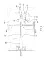
- FIG. 2is a front view of an embodiment of the disclosure.
- FIG. 3is a rear view of an embodiment of the disclosure.
- FIG. 4is a top view of an embodiment of the disclosure.
- FIG. 5is a side view of an embodiment of the disclosure.
- FIG. 6is a perspective in-use view of an embodiment of the disclosure.
- FIGS. 1 through 6a new dental prosthesis mold cutting device embodying the principles and concepts of an embodiment of the disclosure and generally designated by the reference numeral 10 will be described.
- the dental prosthesis mold shaping apparatus 10generally comprises a panel 12 that has an upper side 14 .
- the panel 12may include a conventional countertop, tabletop or the like.
- a cutting assembly 16is attached to the panel 12 and extends upwardly from the upper side 14 .
- the cutting assembly 16is configured to cut into a conventional dental prosthesis mold 70 .
- the cutting assembly 16comprises a saw assembly having a disc shaped blade 18 attached thereto. More particularly, the saw assembly 10 includes an electric motor 20 driving a mandrel 21 to which the disc shaped blade 18 is attached.
- the disc 18is a conventional bladed, cutting disc utilized for cutting plaster such as is available from Renfert USA, 3718 Illinois Avenue, St. Charles Ill., 60174.
- the motor 20is actuated with a foot pedal 22 and a modulator 23 may be utilized to better control the amount of power provided to the motor 20 .
- a support 24is attached to the saw assembly 16 and supports the saw assembly 16 above the upper side 14 .
- the support 24is configured to allow vertical movement of the saw assembly 16 with respect to the upper side 14 and restrict lateral movement of the saw assembly 16 .
- the support 24retains the disc 18 in a plane oriented perpendicular to a plane of the upper side 14 .
- the support 24includes a base 26 that is attached to the panel 12 and an arm 30 that is pivotally coupled to the base 26 .
- the arm 30has a distal end 32 with respect to the base 26 and the saw assembly 16 is attached to the distal end 32 .
- a pair of lateral buttresses 34is attached to the panel 12 and the arm 30 is positioned between the lateral buttresses 34 .
- a rod 36is coupled to each of the lateral buttresses 34 and is vertically slidable on each of the lateral buttresses 34 .
- the rod 36is attached to the arm 30 .
- the arm 30may include a pair of sections 38 , 40 pivotally coupled together to allow for a distance between the distal end 32 and the base 26 to vary as the distal end 32 is vertically manipulated.
- the rod 36may include a pair of ends each comprising a hub 42 positioned within vertical slots 44 in the lateral buttresses 34 .
- the hubs 42are allowed to move upwardly and downwardly within the slots 44 .
- a tensioning handle 46may be utilized and coupled to the arm 30 and the base 26 to adjust the ease of movement of the arm 30 relative to the base 26 .
- a saddle 46 for receiving the mold 70includes a mount 48 and a plate 50 .
- the mount 48is releasably coupled to the upper side 14 .
- the plate 50is configured to releasably receive the dental prosthesis mold 70 .
- the mount 48comprises a conventional suction cup 49 releasably engaging the upper side 14 .
- the plate 50has a top side 51 , a front edge 52 , a rear edge 53 and a pair of side edges 54 .
- a front bracket 55is attached to and extends upwardly from the plate 50 adjacent to the front edge 52 and a rear bracket 56 is attached to and extends upwardly from the plate 50 adjacent to the rear edge 53 .
- a distance between the front 55 and rear 56 bracketsis adjustable to frictionally engage the dental prosthesis mold 70 .
- front 55 and/or rear 56 bracketsare threadably coupled to the plate 50 to allow them to be moved by actuating a head 57 of a threaded member to urge the front 55 and rear 56 brackets toward each other and engage the mold 70 .
- the plate 50may be pivotable with respect to the mount 48 .
- a stop 60may be attached to the panel 12 to restrict vertical movement of the cutting assembly 16 .
- the stop 60has a selectively adjustable height.
- the stop 60may include a cylinder 62 and a post 64 threadably engaged to the cylinder 62 .
- the post 64is raised or lowered as needed to engage the rod at a height a user of the apparatus 10 does not want the rod 36 to move lower than. In this manner, the stop 60 prevents the accidental deep cutting into the mold 70 by the cutting assembly 16 .
- the mold 70is placed in the saddle as is shown in FIG. 6 and is frictionally held in place as described above utilizing the front 55 and rear 56 brackets.
- the stop 60may be positioned at a selected height as needed.
- the cutting assembly 16is then used to make detailed cuts to the mold as needed to prepare it for use in making a dental prosthesis.
- the apparatus 10ensures that fine, detailed cuts can be made with less risk of cutting too deep or laterally of the intended position of the desired cut.
Landscapes
- Engineering & Computer Science (AREA)
- Mechanical Engineering (AREA)
- Life Sciences & Earth Sciences (AREA)
- Wood Science & Technology (AREA)
- Forests & Forestry (AREA)
- Dental Tools And Instruments Or Auxiliary Dental Instruments (AREA)
Abstract
Description
The disclosure relates to dental prosthesis mold cutting devices and more particularly pertains to a new dental prosthesis mold cutting device for assisting a person in making precise cuts into a dental prosthesis mold.
An embodiment of the disclosure meets the needs presented above by generally comprising a panel that has an upper side and a cutting assembly that is attached to the panel and extends upwardly from the upper side. The cutting assembly is configured to cut into a dental prosthesis mold. The cutting assembly has restricted lateral movement and unrestricted vertical movement. A saddle includes a mount and a plate. The mount is releasably coupled to the upper side and the plate is configured to releasably receive the dental prosthesis mold. The saddle is configured to support the dental prosthesis mold while the dental prosthesis mold is being cut.
There has thus been outlined, rather broadly, the more important features of the disclosure in order that the detailed description thereof that follows may be better understood, and in order that the present contribution to the art may be better appreciated. There are additional features of the disclosure that will be described hereinafter and which will form the subject matter of the claims appended hereto.
The objects of the disclosure, along with the various features of novelty which characterize the disclosure, are pointed out with particularity in the claims annexed to and forming a part of this disclosure.
The disclosure will be better understood and objects other than those set forth above will become apparent when consideration is given to the following detailed description thereof. Such description makes reference to the annexed drawings wherein:
With reference now to the drawings, and in particular toFIGS. 1 through 6 thereof, a new dental prosthesis mold cutting device embodying the principles and concepts of an embodiment of the disclosure and generally designated by thereference numeral 10 will be described.
As best illustrated inFIGS. 1 through 6 , the dental prosthesismold shaping apparatus 10 generally comprises apanel 12 that has anupper side 14. Thepanel 12 may include a conventional countertop, tabletop or the like.
Acutting assembly 16 is attached to thepanel 12 and extends upwardly from theupper side 14. Thecutting assembly 16 is configured to cut into a conventionaldental prosthesis mold 70. Thecutting assembly 16 comprises a saw assembly having a disc shapedblade 18 attached thereto. More particularly, thesaw assembly 10 includes anelectric motor 20 driving amandrel 21 to which the discshaped blade 18 is attached. Thedisc 18 is a conventional bladed, cutting disc utilized for cutting plaster such as is available from Renfert USA, 3718 Illinois Avenue, St. Charles Ill., 60174. Themotor 20 is actuated with afoot pedal 22 and amodulator 23 may be utilized to better control the amount of power provided to themotor 20.
Asupport 24 is attached to thesaw assembly 16 and supports thesaw assembly 16 above theupper side 14. Thesupport 24 is configured to allow vertical movement of thesaw assembly 16 with respect to theupper side 14 and restrict lateral movement of thesaw assembly 16. Thesupport 24 retains thedisc 18 in a plane oriented perpendicular to a plane of theupper side 14. Thesupport 24 includes abase 26 that is attached to thepanel 12 and anarm 30 that is pivotally coupled to thebase 26. Thearm 30 has adistal end 32 with respect to thebase 26 and thesaw assembly 16 is attached to thedistal end 32. A pair oflateral buttresses 34 is attached to thepanel 12 and thearm 30 is positioned between thelateral buttresses 34. Arod 36 is coupled to each of thelateral buttresses 34 and is vertically slidable on each of thelateral buttresses 34. Therod 36 is attached to thearm 30. Thearm 30 may include a pair ofsections distal end 32 and thebase 26 to vary as thedistal end 32 is vertically manipulated. In particular, therod 36 may include a pair of ends each comprising ahub 42 positioned withinvertical slots 44 in thelateral buttresses 34. Thehubs 42 are allowed to move upwardly and downwardly within theslots 44. Additionally, atensioning handle 46 may be utilized and coupled to thearm 30 and thebase 26 to adjust the ease of movement of thearm 30 relative to thebase 26.
Asaddle 46 for receiving themold 70 includes amount 48 and aplate 50. Themount 48 is releasably coupled to theupper side 14. Theplate 50 is configured to releasably receive thedental prosthesis mold 70. Themount 48 comprises aconventional suction cup 49 releasably engaging theupper side 14. Theplate 50 has atop side 51, afront edge 52, arear edge 53 and a pair ofside edges 54. Afront bracket 55 is attached to and extends upwardly from theplate 50 adjacent to thefront edge 52 and arear bracket 56 is attached to and extends upwardly from theplate 50 adjacent to therear edge 53. A distance between thefront 55 and rear56 brackets is adjustable to frictionally engage thedental prosthesis mold 70. In particular, thefront 55 and/or rear56 brackets are threadably coupled to theplate 50 to allow them to be moved by actuating ahead 57 of a threaded member to urge thefront 55 and rear56 brackets toward each other and engage themold 70. Theplate 50 may be pivotable with respect to themount 48.
Astop 60 may be attached to thepanel 12 to restrict vertical movement of thecutting assembly 16. Thestop 60 has a selectively adjustable height. In particular, thestop 60 may include acylinder 62 and apost 64 threadably engaged to thecylinder 62. Thepost 64 is raised or lowered as needed to engage the rod at a height a user of theapparatus 10 does not want therod 36 to move lower than. In this manner, thestop 60 prevents the accidental deep cutting into themold 70 by thecutting assembly 16.
In use, themold 70 is placed in the saddle as is shown inFIG. 6 and is frictionally held in place as described above utilizing thefront 55 and rear56 brackets. Thestop 60 may be positioned at a selected height as needed. Thecutting assembly 16 is then used to make detailed cuts to the mold as needed to prepare it for use in making a dental prosthesis. Theapparatus 10 ensures that fine, detailed cuts can be made with less risk of cutting too deep or laterally of the intended position of the desired cut.
With respect to the above description then, it is to be realized that the optimum dimensional relationships for the parts of an embodiment enabled by the disclosure, to include variations in size, materials, shape, form, function and manner of operation, assembly and use, are deemed readily apparent and obvious to one skilled in the art, and all equivalent relationships to those illustrated in the drawings and described in the specification are intended to be encompassed by an embodiment of the disclosure.
Therefore, the foregoing is considered as illustrative only of the principles of the disclosure. Further, since numerous modifications and changes will readily occur to those skilled in the art, it is not desired to limit the disclosure to the exact construction and operation shown and described, and accordingly, all suitable modifications and equivalents may be resorted to, falling within the scope of the disclosure.
Claims (6)
1. A dental prosthesis mold cutting apparatus for cutting a dental prosthesis mold, said apparatus comprising:
a panel having an upper side;
a cutting assembly being attached to said panel and extending upwardly from said upper side, said cutting assembly being configured to cut into a dental prosthesis mold, said cutting assembly having restricted lateral movement and unrestricted vertical movement, said cutting assembly including;
a disc shaped blade; and
a support being attached to said blade and supporting said blade above said upper side, said support being configured to allow vertical movement of said blade with respect to said upper side and restrict lateral movement of said blade, said support including;
a base being attached to said panel;
an arm being pivotally coupled to said base, said arm having a distal end with respect to said base, said blade being attached to said distal end, said arm including a pair of sections pivotally coupled together to allow for a distance between said distal end and said base to vary as said distal end is vertically manipulated;
a pair of lateral buttresses being attached to said panel, said arm being positioned between said lateral buttresses; and
a rod being coupled to each of said lateral buttresses, said rod being vertically slidable on each of said lateral buttresses, said rod being attached to said arm;
a saddle including a mount and a plate, said mount being releasably coupled to said upper side, said plate being configured to releasably receive the dental prosthesis mold; and
wherein said saddle is configured to support the dental prosthesis mold while the dental prosthesis mold is being cut.
2. The apparatus as inclaim 1 , wherein said mount comprises a suction cup releasably engaging said upper side.
3. The apparatus as inclaim 2 , wherein said plate has a top side, a front edge, a rear edge and a pair of side edges, a front bracket being attached to and extending upwardly from said plate adjacent to said front edge, a rear bracket being attached to said and extending upwardly from said plate adjacent to said rear edge, a distance between said front and rear brackets being adjustable to frictionally engage the dental prosthesis mold.
4. The apparatus as inclaim 1 , wherein said plate has a top side, a front edge, a rear edge and a pair of side edges, a front bracket being attached to and extending upwardly from said plate adjacent to said front edge, a rear bracket being attached to said and extending upwardly from said plate adjacent to said rear edge, a distance between said front and rear brackets being adjustable to frictionally engage the dental prosthesis mold.
5. The apparatus as inclaim 1 , further including a stop being attached to said panel and restricting vertical movement of said cutting assembly, said stop having a selectively adjustable height.
6. A dental prosthesis mold cutting apparatus for cutting a dental prosthesis mold, said apparatus comprising:
a panel having an upper side;
a cutting assembly being attached to said panel and extending upwardly from said upper side, said cutting assembly being configured to cut into a dental prosthesis mold, said cutting assembly including;
a disc shaped blade;
a support being attached to said blade and supporting said blade above said upper side, said support being configured to allow vertical movement of said blade with respect to said upper side and restrict lateral movement of said blade, said support retaining said disc in a plane oriented perpendicular to a plane of said upper side, said support including;
a base being attached to said panel;
an arm being pivotally coupled to said base, said arm having a distal end with respect to said base, said blade being attached to said distal end, said arm including a pair of sections pivotally coupled together to allow for a distance between said distal end and said base to vary as said distal end is vertically manipulated;
a pair of lateral buttresses being attached to said panel, said arm being positioned between said lateral buttresses;
a rod being coupled to each of said lateral buttresses, said rod being vertically slidable on each of said lateral buttresses, said rod being attached to said arm;
a saddle including a mount and a plate, said mount being releasably coupled to said upper side, said plate being configured to releasably receive the dental prosthesis mold, said mount comprising a suction cup releasably engaging said upper side, said plate having a top side, a front edge, a rear edge and a pair of side edges, a front bracket being attached to and extending upwardly from said plate adjacent to said front edge, a rear bracket being attached to said and extending upwardly from said plate adjacent to said rear edge, a distance between said front and rear brackets being adjustable to frictionally engage the dental prosthesis mold; and
a stop being attached to said panel and restricting vertical movement of said cutting assembly, said stop having a selectively adjustable height.
Priority Applications (1)
| Application Number | Priority Date | Filing Date | Title |
|---|---|---|---|
| US13/175,315US8601925B1 (en) | 2011-07-01 | 2011-07-01 | Dental prosthesis mold shaping apparatus |
Applications Claiming Priority (1)
| Application Number | Priority Date | Filing Date | Title |
|---|---|---|---|
| US13/175,315US8601925B1 (en) | 2011-07-01 | 2011-07-01 | Dental prosthesis mold shaping apparatus |
Publications (1)
| Publication Number | Publication Date |
|---|---|
| US8601925B1true US8601925B1 (en) | 2013-12-10 |
Family
ID=49681405
Family Applications (1)
| Application Number | Title | Priority Date | Filing Date |
|---|---|---|---|
| US13/175,315Expired - Fee RelatedUS8601925B1 (en) | 2011-07-01 | 2011-07-01 | Dental prosthesis mold shaping apparatus |
Country Status (1)
| Country | Link |
|---|---|
| US (1) | US8601925B1 (en) |
Cited By (46)
| Publication number | Priority date | Publication date | Assignee | Title |
|---|---|---|---|---|
| US10195690B2 (en)* | 2011-09-21 | 2019-02-05 | Align Technology, Inc. | Laser cutting |
| US10390913B2 (en) | 2018-01-26 | 2019-08-27 | Align Technology, Inc. | Diagnostic intraoral scanning |
| US10470847B2 (en) | 2016-06-17 | 2019-11-12 | Align Technology, Inc. | Intraoral appliances with sensing |
| US10504386B2 (en) | 2015-01-27 | 2019-12-10 | Align Technology, Inc. | Training method and system for oral-cavity-imaging-and-modeling equipment |
| US10509838B2 (en) | 2016-07-27 | 2019-12-17 | Align Technology, Inc. | Methods and apparatuses for forming a three-dimensional volumetric model of a subject's teeth |
| US10517482B2 (en) | 2017-07-27 | 2019-12-31 | Align Technology, Inc. | Optical coherence tomography for orthodontic aligners |
| US10537405B2 (en) | 2014-11-13 | 2020-01-21 | Align Technology, Inc. | Dental appliance with cavity for an unerupted or erupting tooth |
| US10548700B2 (en) | 2016-12-16 | 2020-02-04 | Align Technology, Inc. | Dental appliance etch template |
| US10595966B2 (en) | 2016-11-04 | 2020-03-24 | Align Technology, Inc. | Methods and apparatuses for dental images |
| US10610332B2 (en) | 2012-05-22 | 2020-04-07 | Align Technology, Inc. | Adjustment of tooth position in a virtual dental model |
| US10613515B2 (en) | 2017-03-31 | 2020-04-07 | Align Technology, Inc. | Orthodontic appliances including at least partially un-erupted teeth and method of forming them |
| US10639134B2 (en) | 2017-06-26 | 2020-05-05 | Align Technology, Inc. | Biosensor performance indicator for intraoral appliances |
| US10779718B2 (en) | 2017-02-13 | 2020-09-22 | Align Technology, Inc. | Cheek retractor and mobile device holder |
| US10813720B2 (en) | 2017-10-05 | 2020-10-27 | Align Technology, Inc. | Interproximal reduction templates |
| US10885521B2 (en) | 2017-07-17 | 2021-01-05 | Align Technology, Inc. | Method and apparatuses for interactive ordering of dental aligners |
| US10893918B2 (en) | 2012-03-01 | 2021-01-19 | Align Technology, Inc. | Determining a dental treatment difficulty |
| US10980613B2 (en) | 2017-12-29 | 2021-04-20 | Align Technology, Inc. | Augmented reality enhancements for dental practitioners |
| US10993783B2 (en) | 2016-12-02 | 2021-05-04 | Align Technology, Inc. | Methods and apparatuses for customizing a rapid palatal expander |
| US11026831B2 (en) | 2016-12-02 | 2021-06-08 | Align Technology, Inc. | Dental appliance features for speech enhancement |
| US11045283B2 (en) | 2017-06-09 | 2021-06-29 | Align Technology, Inc. | Palatal expander with skeletal anchorage devices |
| US11096763B2 (en) | 2017-11-01 | 2021-08-24 | Align Technology, Inc. | Automatic treatment planning |
| US11103330B2 (en) | 2015-12-09 | 2021-08-31 | Align Technology, Inc. | Dental attachment placement structure |
| US11116605B2 (en) | 2017-08-15 | 2021-09-14 | Align Technology, Inc. | Buccal corridor assessment and computation |
| US11123156B2 (en) | 2017-08-17 | 2021-09-21 | Align Technology, Inc. | Dental appliance compliance monitoring |
| US11219506B2 (en) | 2017-11-30 | 2022-01-11 | Align Technology, Inc. | Sensors for monitoring oral appliances |
| US11273011B2 (en) | 2016-12-02 | 2022-03-15 | Align Technology, Inc. | Palatal expanders and methods of expanding a palate |
| US11376101B2 (en) | 2016-12-02 | 2022-07-05 | Align Technology, Inc. | Force control, stop mechanism, regulating structure of removable arch adjustment appliance |
| US11419702B2 (en) | 2017-07-21 | 2022-08-23 | Align Technology, Inc. | Palatal contour anchorage |
| US11426259B2 (en) | 2012-02-02 | 2022-08-30 | Align Technology, Inc. | Identifying forces on a tooth |
| US11432908B2 (en) | 2017-12-15 | 2022-09-06 | Align Technology, Inc. | Closed loop adaptive orthodontic treatment methods and apparatuses |
| US11534974B2 (en) | 2017-11-17 | 2022-12-27 | Align Technology, Inc. | Customized fabrication of orthodontic retainers based on patient anatomy |
| US11534268B2 (en) | 2017-10-27 | 2022-12-27 | Align Technology, Inc. | Alternative bite adjustment structures |
| US11554000B2 (en) | 2015-11-12 | 2023-01-17 | Align Technology, Inc. | Dental attachment formation structure |
| US11564777B2 (en) | 2018-04-11 | 2023-01-31 | Align Technology, Inc. | Releasable palatal expanders |
| US11576752B2 (en) | 2017-10-31 | 2023-02-14 | Align Technology, Inc. | Dental appliance having selective occlusal loading and controlled intercuspation |
| US11596502B2 (en) | 2015-12-09 | 2023-03-07 | Align Technology, Inc. | Dental attachment placement structure |
| US11612455B2 (en) | 2016-06-17 | 2023-03-28 | Align Technology, Inc. | Orthodontic appliance performance monitor |
| US11633268B2 (en) | 2017-07-27 | 2023-04-25 | Align Technology, Inc. | Tooth shading, transparency and glazing |
| US11638629B2 (en) | 2014-09-19 | 2023-05-02 | Align Technology, Inc. | Arch expanding appliance |
| US11744677B2 (en) | 2014-09-19 | 2023-09-05 | Align Technology, Inc. | Arch adjustment appliance |
| US11931222B2 (en) | 2015-11-12 | 2024-03-19 | Align Technology, Inc. | Dental attachment formation structures |
| US11937991B2 (en) | 2018-03-27 | 2024-03-26 | Align Technology, Inc. | Dental attachment placement structure |
| US11996181B2 (en) | 2017-06-16 | 2024-05-28 | Align Technology, Inc. | Automatic detection of tooth type and eruption status |
| US12090020B2 (en) | 2017-03-27 | 2024-09-17 | Align Technology, Inc. | Apparatuses and methods assisting in dental therapies |
| US12171575B2 (en) | 2017-10-04 | 2024-12-24 | Align Technology, Inc. | Intraoral systems and methods for sampling soft-tissue |
| US12274597B2 (en) | 2017-08-11 | 2025-04-15 | Align Technology, Inc. | Dental attachment template tray systems |
Citations (16)
| Publication number | Priority date | Publication date | Assignee | Title |
|---|---|---|---|---|
| US1697434A (en)* | 1926-05-19 | 1929-01-01 | Locke Insulator Corp | Hole-cutting machine |
| US2454427A (en) | 1947-09-15 | 1948-11-23 | Dell E Bell | Device for removing extruded plaster from exterior surfaces of dental flasks |
| US2614326A (en)* | 1949-10-13 | 1952-10-21 | Oscar H Loock | Mold trimmer |
| US3057240A (en)* | 1958-08-15 | 1962-10-09 | Wallace Supplies Mfg Company | Cut-off machine work clamp |
| US3936981A (en) | 1974-05-06 | 1976-02-10 | White Velton C | Dental model trimmer |
| USD244938S (en)* | 1976-01-12 | 1977-07-05 | Viazzoli Alfred A | Dental saw |
| US4074436A (en) | 1975-07-15 | 1978-02-21 | Premach Pty. Limited | Apparatus for use in shaping a tubular dental impression accessory |
| US4182615A (en) | 1978-01-05 | 1980-01-08 | Ipco Hospital Supply Corporation | Dental model trimmer |
| US4567802A (en)* | 1984-10-22 | 1986-02-04 | Witherspoon John K | Mortise and bevel cutter |
| US4625611A (en)* | 1985-04-10 | 1986-12-02 | General Medical Products, Inc. | Method and apparatus for removing the outermost layer of a multilayered product |
| US4815350A (en)* | 1986-10-23 | 1989-03-28 | Chr. Eisele Maschinenfabrik Gmbh & Co. Kg | Circular saw machine |
| US4817839A (en) | 1987-02-13 | 1989-04-04 | Ipco Corporation | Rotary saw and method for sectioning dental models |
| US6619959B2 (en) | 2001-01-31 | 2003-09-16 | Gc Corporation | Process for preparing dental prosthesis |
| US6974323B2 (en) | 2002-04-14 | 2005-12-13 | Paul Weigl | Method for automated production of ceramic dental restorations and prostheses |
| US7059231B2 (en) | 2003-05-19 | 2006-06-13 | Neil John Graham | Dental model cutter |
| US20110106019A1 (en)* | 2007-11-21 | 2011-05-05 | Piezo Resonance Innovations, Inc. | Devices for clearing blockages in in-situ artificial lumens |
- 2011
- 2011-07-01USUS13/175,315patent/US8601925B1/ennot_activeExpired - Fee Related
Patent Citations (16)
| Publication number | Priority date | Publication date | Assignee | Title |
|---|---|---|---|---|
| US1697434A (en)* | 1926-05-19 | 1929-01-01 | Locke Insulator Corp | Hole-cutting machine |
| US2454427A (en) | 1947-09-15 | 1948-11-23 | Dell E Bell | Device for removing extruded plaster from exterior surfaces of dental flasks |
| US2614326A (en)* | 1949-10-13 | 1952-10-21 | Oscar H Loock | Mold trimmer |
| US3057240A (en)* | 1958-08-15 | 1962-10-09 | Wallace Supplies Mfg Company | Cut-off machine work clamp |
| US3936981A (en) | 1974-05-06 | 1976-02-10 | White Velton C | Dental model trimmer |
| US4074436A (en) | 1975-07-15 | 1978-02-21 | Premach Pty. Limited | Apparatus for use in shaping a tubular dental impression accessory |
| USD244938S (en)* | 1976-01-12 | 1977-07-05 | Viazzoli Alfred A | Dental saw |
| US4182615A (en) | 1978-01-05 | 1980-01-08 | Ipco Hospital Supply Corporation | Dental model trimmer |
| US4567802A (en)* | 1984-10-22 | 1986-02-04 | Witherspoon John K | Mortise and bevel cutter |
| US4625611A (en)* | 1985-04-10 | 1986-12-02 | General Medical Products, Inc. | Method and apparatus for removing the outermost layer of a multilayered product |
| US4815350A (en)* | 1986-10-23 | 1989-03-28 | Chr. Eisele Maschinenfabrik Gmbh & Co. Kg | Circular saw machine |
| US4817839A (en) | 1987-02-13 | 1989-04-04 | Ipco Corporation | Rotary saw and method for sectioning dental models |
| US6619959B2 (en) | 2001-01-31 | 2003-09-16 | Gc Corporation | Process for preparing dental prosthesis |
| US6974323B2 (en) | 2002-04-14 | 2005-12-13 | Paul Weigl | Method for automated production of ceramic dental restorations and prostheses |
| US7059231B2 (en) | 2003-05-19 | 2006-06-13 | Neil John Graham | Dental model cutter |
| US20110106019A1 (en)* | 2007-11-21 | 2011-05-05 | Piezo Resonance Innovations, Inc. | Devices for clearing blockages in in-situ artificial lumens |
Cited By (59)
| Publication number | Priority date | Publication date | Assignee | Title |
|---|---|---|---|---|
| US20240066628A1 (en)* | 2011-09-21 | 2024-02-29 | Align Technology, Inc. | Laser cutting |
| US10195690B2 (en)* | 2011-09-21 | 2019-02-05 | Align Technology, Inc. | Laser cutting |
| US12377493B2 (en)* | 2011-09-21 | 2025-08-05 | Align Technology, Inc. | Laser cutting |
| US11534861B2 (en)* | 2011-09-21 | 2022-12-27 | Align Technology, Inc. | Laser cutting |
| US20190337091A1 (en)* | 2011-09-21 | 2019-11-07 | Align Technology, Inc. | Laser cutting |
| US10828719B2 (en)* | 2011-09-21 | 2020-11-10 | Align Technology, Inc. | Laser cutting |
| US10773337B2 (en)* | 2011-09-21 | 2020-09-15 | Align Technology, Inc. | Laser cutting |
| US11383322B2 (en)* | 2011-09-21 | 2022-07-12 | Align Technology, Inc. | Laser cutting |
| US20190240771A1 (en)* | 2011-09-21 | 2019-08-08 | Align Technology, Inc. | Laser cutting |
| US10421152B2 (en)* | 2011-09-21 | 2019-09-24 | Align Technology, Inc. | Laser cutting |
| US11426259B2 (en) | 2012-02-02 | 2022-08-30 | Align Technology, Inc. | Identifying forces on a tooth |
| US10893918B2 (en) | 2012-03-01 | 2021-01-19 | Align Technology, Inc. | Determining a dental treatment difficulty |
| US10610332B2 (en) | 2012-05-22 | 2020-04-07 | Align Technology, Inc. | Adjustment of tooth position in a virtual dental model |
| US11744677B2 (en) | 2014-09-19 | 2023-09-05 | Align Technology, Inc. | Arch adjustment appliance |
| US11638629B2 (en) | 2014-09-19 | 2023-05-02 | Align Technology, Inc. | Arch expanding appliance |
| US10537405B2 (en) | 2014-11-13 | 2020-01-21 | Align Technology, Inc. | Dental appliance with cavity for an unerupted or erupting tooth |
| US10504386B2 (en) | 2015-01-27 | 2019-12-10 | Align Technology, Inc. | Training method and system for oral-cavity-imaging-and-modeling equipment |
| US11931222B2 (en) | 2015-11-12 | 2024-03-19 | Align Technology, Inc. | Dental attachment formation structures |
| US11554000B2 (en) | 2015-11-12 | 2023-01-17 | Align Technology, Inc. | Dental attachment formation structure |
| US11596502B2 (en) | 2015-12-09 | 2023-03-07 | Align Technology, Inc. | Dental attachment placement structure |
| US11103330B2 (en) | 2015-12-09 | 2021-08-31 | Align Technology, Inc. | Dental attachment placement structure |
| US11612455B2 (en) | 2016-06-17 | 2023-03-28 | Align Technology, Inc. | Orthodontic appliance performance monitor |
| US10470847B2 (en) | 2016-06-17 | 2019-11-12 | Align Technology, Inc. | Intraoral appliances with sensing |
| US10606911B2 (en) | 2016-07-27 | 2020-03-31 | Align Technology, Inc. | Intraoral scanner with dental diagnostics capabilities |
| US10509838B2 (en) | 2016-07-27 | 2019-12-17 | Align Technology, Inc. | Methods and apparatuses for forming a three-dimensional volumetric model of a subject's teeth |
| US10585958B2 (en) | 2016-07-27 | 2020-03-10 | Align Technology, Inc. | Intraoral scanner with dental diagnostics capabilities |
| US10595966B2 (en) | 2016-11-04 | 2020-03-24 | Align Technology, Inc. | Methods and apparatuses for dental images |
| US11273011B2 (en) | 2016-12-02 | 2022-03-15 | Align Technology, Inc. | Palatal expanders and methods of expanding a palate |
| US10993783B2 (en) | 2016-12-02 | 2021-05-04 | Align Technology, Inc. | Methods and apparatuses for customizing a rapid palatal expander |
| US11026831B2 (en) | 2016-12-02 | 2021-06-08 | Align Technology, Inc. | Dental appliance features for speech enhancement |
| US11376101B2 (en) | 2016-12-02 | 2022-07-05 | Align Technology, Inc. | Force control, stop mechanism, regulating structure of removable arch adjustment appliance |
| US10548700B2 (en) | 2016-12-16 | 2020-02-04 | Align Technology, Inc. | Dental appliance etch template |
| US10779718B2 (en) | 2017-02-13 | 2020-09-22 | Align Technology, Inc. | Cheek retractor and mobile device holder |
| US12090020B2 (en) | 2017-03-27 | 2024-09-17 | Align Technology, Inc. | Apparatuses and methods assisting in dental therapies |
| US10613515B2 (en) | 2017-03-31 | 2020-04-07 | Align Technology, Inc. | Orthodontic appliances including at least partially un-erupted teeth and method of forming them |
| US11045283B2 (en) | 2017-06-09 | 2021-06-29 | Align Technology, Inc. | Palatal expander with skeletal anchorage devices |
| US11996181B2 (en) | 2017-06-16 | 2024-05-28 | Align Technology, Inc. | Automatic detection of tooth type and eruption status |
| US10639134B2 (en) | 2017-06-26 | 2020-05-05 | Align Technology, Inc. | Biosensor performance indicator for intraoral appliances |
| US10885521B2 (en) | 2017-07-17 | 2021-01-05 | Align Technology, Inc. | Method and apparatuses for interactive ordering of dental aligners |
| US11419702B2 (en) | 2017-07-21 | 2022-08-23 | Align Technology, Inc. | Palatal contour anchorage |
| US10517482B2 (en) | 2017-07-27 | 2019-12-31 | Align Technology, Inc. | Optical coherence tomography for orthodontic aligners |
| US11633268B2 (en) | 2017-07-27 | 2023-04-25 | Align Technology, Inc. | Tooth shading, transparency and glazing |
| US12274597B2 (en) | 2017-08-11 | 2025-04-15 | Align Technology, Inc. | Dental attachment template tray systems |
| US11116605B2 (en) | 2017-08-15 | 2021-09-14 | Align Technology, Inc. | Buccal corridor assessment and computation |
| US11123156B2 (en) | 2017-08-17 | 2021-09-21 | Align Technology, Inc. | Dental appliance compliance monitoring |
| US12171575B2 (en) | 2017-10-04 | 2024-12-24 | Align Technology, Inc. | Intraoral systems and methods for sampling soft-tissue |
| US10813720B2 (en) | 2017-10-05 | 2020-10-27 | Align Technology, Inc. | Interproximal reduction templates |
| US11534268B2 (en) | 2017-10-27 | 2022-12-27 | Align Technology, Inc. | Alternative bite adjustment structures |
| US11576752B2 (en) | 2017-10-31 | 2023-02-14 | Align Technology, Inc. | Dental appliance having selective occlusal loading and controlled intercuspation |
| US11096763B2 (en) | 2017-11-01 | 2021-08-24 | Align Technology, Inc. | Automatic treatment planning |
| US11534974B2 (en) | 2017-11-17 | 2022-12-27 | Align Technology, Inc. | Customized fabrication of orthodontic retainers based on patient anatomy |
| US11219506B2 (en) | 2017-11-30 | 2022-01-11 | Align Technology, Inc. | Sensors for monitoring oral appliances |
| US11432908B2 (en) | 2017-12-15 | 2022-09-06 | Align Technology, Inc. | Closed loop adaptive orthodontic treatment methods and apparatuses |
| US10980613B2 (en) | 2017-12-29 | 2021-04-20 | Align Technology, Inc. | Augmented reality enhancements for dental practitioners |
| US10813727B2 (en) | 2018-01-26 | 2020-10-27 | Align Technology, Inc. | Diagnostic intraoral tracking |
| US11013581B2 (en) | 2018-01-26 | 2021-05-25 | Align Technology, Inc. | Diagnostic intraoral methods and apparatuses |
| US10390913B2 (en) | 2018-01-26 | 2019-08-27 | Align Technology, Inc. | Diagnostic intraoral scanning |
| US11937991B2 (en) | 2018-03-27 | 2024-03-26 | Align Technology, Inc. | Dental attachment placement structure |
| US11564777B2 (en) | 2018-04-11 | 2023-01-31 | Align Technology, Inc. | Releasable palatal expanders |
Similar Documents
| Publication | Publication Date | Title |
|---|---|---|
| US8601925B1 (en) | Dental prosthesis mold shaping apparatus | |
| RU2011108306A (en) | CUTTING TOOLS | |
| CN105397184B (en) | Foldable saw cutting machine and folding method thereof | |
| CN203087060U (en) | Automatic semishrub trimming machine | |
| CN208128941U (en) | A kind of highly-safe agricultural branch pruning device | |
| US8418704B1 (en) | Power adjustable crutch assembly | |
| CN204218977U (en) | A kind of bone surgery cutting knife saw | |
| CN209830955U (en) | Cutting machine capable of adjusting plate cutting angle | |
| KR101539534B1 (en) | Device for cutting street block | |
| CN204217822U (en) | Coconut is opened and is got device | |
| KR200479394Y1 (en) | Safety supporting device for hand grinder | |
| CN104739585B (en) | Gypsum remove device | |
| CN213005433U (en) | Semi-automatic cutting device for rubber pads | |
| CN206869956U (en) | A kind of adjustable for height Biodegradable film cutting equipment | |
| CN204033503U (en) | A kind of hospital anesthesia surgery tray rack | |
| CN105293884A (en) | Circular glass cutting mechanism | |
| CN204939278U (en) | A kind of circular glass cutting mechanism | |
| CN210420690U (en) | Cutting mechanism for multilayer three-dimensional dustproof gauze | |
| CN208604139U (en) | Leatherware processes fillet cutter device | |
| KR101531748B1 (en) | The noumenon a straw cutter | |
| CN103658820A (en) | Die cutting rule with adjustable sliding block | |
| CN203541690U (en) | Rack type oil level sensor die cutter | |
| CN212372243U (en) | Edge cutting device for plastic film processing | |
| CN215471323U (en) | Edge cutting device for decorative film | |
| CN211218480U (en) | A titanium mesh trimming device |
Legal Events
| Date | Code | Title | Description |
|---|---|---|---|
| REMI | Maintenance fee reminder mailed | ||
| LAPS | Lapse for failure to pay maintenance fees | Free format text:PATENT EXPIRED FOR FAILURE TO PAY MAINTENANCE FEES (ORIGINAL EVENT CODE: EXP.) | |
| STCH | Information on status: patent discontinuation | Free format text:PATENT EXPIRED DUE TO NONPAYMENT OF MAINTENANCE FEES UNDER 37 CFR 1.362 | |
| FP | Lapsed due to failure to pay maintenance fee | Effective date:20171210 |