US8601514B1 - PC media center and extension device for a home entertainment system - Google Patents
PC media center and extension device for a home entertainment systemDownload PDFInfo
- Publication number
- US8601514B1 US8601514B1US10/259,200US25920002AUS8601514B1US 8601514 B1US8601514 B1US 8601514B1US 25920002 AUS25920002 AUS 25920002AUS 8601514 B1US8601514 B1US 8601514B1
- Authority
- US
- United States
- Prior art keywords
- media
- media center
- personal computer
- stream
- extension device
- Prior art date
- Legal status (The legal status is an assumption and is not a legal conclusion. Google has not performed a legal analysis and makes no representation as to the accuracy of the status listed.)
- Active, expires
Links
Images


Classifications
- H—ELECTRICITY
- H04—ELECTRIC COMMUNICATION TECHNIQUE
- H04N—PICTORIAL COMMUNICATION, e.g. TELEVISION
- H04N21/00—Selective content distribution, e.g. interactive television or video on demand [VOD]
- H04N21/40—Client devices specifically adapted for the reception of or interaction with content, e.g. set-top-box [STB]; Operations thereof
- H04N21/43—Processing of content or additional data, e.g. demultiplexing additional data from a digital video stream; Elementary client operations, e.g. monitoring of home network or synchronising decoder's clock; Client middleware
- H04N21/436—Interfacing a local distribution network, e.g. communicating with another STB or one or more peripheral devices inside the home
- H04N21/43622—Interfacing an external recording device
- H—ELECTRICITY
- H04—ELECTRIC COMMUNICATION TECHNIQUE
- H04N—PICTORIAL COMMUNICATION, e.g. TELEVISION
- H04N21/00—Selective content distribution, e.g. interactive television or video on demand [VOD]
- H04N21/40—Client devices specifically adapted for the reception of or interaction with content, e.g. set-top-box [STB]; Operations thereof
- H04N21/41—Structure of client; Structure of client peripherals
- H04N21/4104—Peripherals receiving signals from specially adapted client devices
- H04N21/4135—Peripherals receiving signals from specially adapted client devices external recorder
- H—ELECTRICITY
- H04—ELECTRIC COMMUNICATION TECHNIQUE
- H04N—PICTORIAL COMMUNICATION, e.g. TELEVISION
- H04N21/00—Selective content distribution, e.g. interactive television or video on demand [VOD]
- H04N21/40—Client devices specifically adapted for the reception of or interaction with content, e.g. set-top-box [STB]; Operations thereof
- H04N21/41—Structure of client; Structure of client peripherals
- H04N21/414—Specialised client platforms, e.g. receiver in car or embedded in a mobile appliance
- H04N21/4143—Specialised client platforms, e.g. receiver in car or embedded in a mobile appliance embedded in a Personal Computer [PC]
- H—ELECTRICITY
- H04—ELECTRIC COMMUNICATION TECHNIQUE
- H04N—PICTORIAL COMMUNICATION, e.g. TELEVISION
- H04N21/00—Selective content distribution, e.g. interactive television or video on demand [VOD]
- H04N21/40—Client devices specifically adapted for the reception of or interaction with content, e.g. set-top-box [STB]; Operations thereof
- H04N21/41—Structure of client; Structure of client peripherals
- H04N21/414—Specialised client platforms, e.g. receiver in car or embedded in a mobile appliance
- H04N21/4147—PVR [Personal Video Recorder]
- H—ELECTRICITY
- H04—ELECTRIC COMMUNICATION TECHNIQUE
- H04N—PICTORIAL COMMUNICATION, e.g. TELEVISION
- H04N21/00—Selective content distribution, e.g. interactive television or video on demand [VOD]
- H04N21/40—Client devices specifically adapted for the reception of or interaction with content, e.g. set-top-box [STB]; Operations thereof
- H04N21/41—Structure of client; Structure of client peripherals
- H04N21/422—Input-only peripherals, i.e. input devices connected to specially adapted client devices, e.g. global positioning system [GPS]
- H04N21/42204—User interfaces specially adapted for controlling a client device through a remote control device; Remote control devices therefor
- H04N21/42206—User interfaces specially adapted for controlling a client device through a remote control device; Remote control devices therefor characterized by hardware details
- H04N21/4222—Remote control device emulator integrated into a non-television apparatus, e.g. a PDA, media center or smart toy
- H—ELECTRICITY
- H04—ELECTRIC COMMUNICATION TECHNIQUE
- H04N—PICTORIAL COMMUNICATION, e.g. TELEVISION
- H04N21/00—Selective content distribution, e.g. interactive television or video on demand [VOD]
- H04N21/40—Client devices specifically adapted for the reception of or interaction with content, e.g. set-top-box [STB]; Operations thereof
- H04N21/41—Structure of client; Structure of client peripherals
- H04N21/426—Internal components of the client ; Characteristics thereof
- H04N21/42607—Internal components of the client ; Characteristics thereof for processing the incoming bitstream
- H04N21/4263—Internal components of the client ; Characteristics thereof for processing the incoming bitstream involving specific tuning arrangements, e.g. two tuners
- H—ELECTRICITY
- H04—ELECTRIC COMMUNICATION TECHNIQUE
- H04N—PICTORIAL COMMUNICATION, e.g. TELEVISION
- H04N21/00—Selective content distribution, e.g. interactive television or video on demand [VOD]
- H04N21/40—Client devices specifically adapted for the reception of or interaction with content, e.g. set-top-box [STB]; Operations thereof
- H04N21/43—Processing of content or additional data, e.g. demultiplexing additional data from a digital video stream; Elementary client operations, e.g. monitoring of home network or synchronising decoder's clock; Client middleware
- H04N21/436—Interfacing a local distribution network, e.g. communicating with another STB or one or more peripheral devices inside the home
- H04N21/43615—Interfacing a Home Network, e.g. for connecting the client to a plurality of peripherals
- H—ELECTRICITY
- H04—ELECTRIC COMMUNICATION TECHNIQUE
- H04N—PICTORIAL COMMUNICATION, e.g. TELEVISION
- H04N21/00—Selective content distribution, e.g. interactive television or video on demand [VOD]
- H04N21/40—Client devices specifically adapted for the reception of or interaction with content, e.g. set-top-box [STB]; Operations thereof
- H04N21/43—Processing of content or additional data, e.g. demultiplexing additional data from a digital video stream; Elementary client operations, e.g. monitoring of home network or synchronising decoder's clock; Client middleware
- H04N21/44—Processing of video elementary streams, e.g. splicing a video clip retrieved from local storage with an incoming video stream or rendering scenes according to encoded video stream scene graphs
- H04N21/4402—Processing of video elementary streams, e.g. splicing a video clip retrieved from local storage with an incoming video stream or rendering scenes according to encoded video stream scene graphs involving reformatting operations of video signals for household redistribution, storage or real-time display
- H04N21/440218—Processing of video elementary streams, e.g. splicing a video clip retrieved from local storage with an incoming video stream or rendering scenes according to encoded video stream scene graphs involving reformatting operations of video signals for household redistribution, storage or real-time display by transcoding between formats or standards, e.g. from MPEG-2 to MPEG-4
- H—ELECTRICITY
- H04—ELECTRIC COMMUNICATION TECHNIQUE
- H04N—PICTORIAL COMMUNICATION, e.g. TELEVISION
- H04N21/00—Selective content distribution, e.g. interactive television or video on demand [VOD]
- H04N21/40—Client devices specifically adapted for the reception of or interaction with content, e.g. set-top-box [STB]; Operations thereof
- H04N21/43—Processing of content or additional data, e.g. demultiplexing additional data from a digital video stream; Elementary client operations, e.g. monitoring of home network or synchronising decoder's clock; Client middleware
- H04N21/443—OS processes, e.g. booting an STB, implementing a Java virtual machine in an STB or power management in an STB
- H04N21/4432—Powering on the client, e.g. bootstrap loading using setup parameters being stored locally or received from the server
Definitions
- the present inventionrelates generally to home entertainment systems. More specifically, the present invention relates to a PC media center and extension device for a home entertainment system.
- FIG. 1is a block diagram of a system for distributing media content to subscribers
- FIG. 2is a block diagram of a standard set top box (STB);
- FIG. 3is a block diagram of an advanced STB
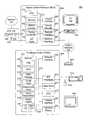
- FIG. 4is a block diagram of home entertainment system including a PC media center (PCMC) and a media center extension (MCX);
- PCMCPC media center
- MCXmedia center extension
- FIG. 5is a block diagram of a home entertainment system showing details of a PCMC and MCX;
- FIG. 6is a dataflow diagram of the system of FIG. 5 ;
- FIG. 7is a detailed block diagram of an alternative home entertainment system showing details of a PCMC and MCX;
- FIG. 8is a dataflow diagram of the system of FIG. 6 ;
- FIG. 9is a block diagram of a home entertainment system including multiple televisions.
- FIG. 10is a flowchart of a method performed by a home entertainment system.
- Coupledrefers not only to components that are directly connected, but also to components that are connected via one or more other components. Hence, the term “coupled” may also refer to components that are in communication with one another, although no physical or direct connection may exist.
- a typical system 100 for distributing media content to subscribersincludes one or more content sources 101 linked to plurality of set top boxes (STBs) 102 by a broadband network 103 .
- content sources 101may include television networks, websites, video servers, music servers, software archives, databases, and the like.
- An STB 102receives encoded television signals and data from the content source(s) 101 via the network 103 and displays the same on a television (TV) 104 or similar display device.
- TVtelevision
- an STB 102is typically located in close proximity to the TV 104 (i.e. the STB 102 and the TV 104 are “collocated”).
- each TV 104must have its own STB 102 in order to receive and display media content.
- the broadband network 103is typically a cable TV network or a direct broadcast satellite (DBS) network, although other networks are possible.
- the STBs 102may be coupled to the network 103 directly or through one or more broadcast centers 105 .
- a broadcast center 105is referred to as a “head-end”, which is a centrally-located facility within a community in which TV programming is received from a local cable TV satellite downlink or other source and packaged for transmission to subscriber homes.
- a broadcast center 105may also be embodied as a satellite broadcast center within a DBS network.
- Broadcast centers 105may be coupled directly to one another or through the broadband network 103 . In some cases, broadcast centers 105 may be connected via a separate network, one particular example of which is the Internet 108 . Communication over the Internet 108 is accomplished using TCP/IP and other standard protocols.
- a remote control 106is generally provided for convenient remote operation of the STB 102 and the TV 104 .
- the remote control 106may use infrared (IR), radio frequency (RF), or other wireless technologies to transmit control signals to the STB 102 and the TV 104 .
- IRinfrared
- RFradio frequency
- FIG. 2is a block diagram of a home entertainment system 200 including a standard STB 102 , such as a MotorolaTM DCT2000TM. As depicted, the STB 102 includes a tuner 202 for selectively receiving media content from the broadband network 103 on different channels or frequencies. Various analog tuners 202 are available, such as the BroadcomTM BCM 7031TM.
- a “digital” tuner 202may include circuitry for selectively demodulating, demultiplexing, and decoding such content.
- the STB 102may also include a conditional access (CA) device 204 for decrypting media content for premium and pay-per-view (PPV) channels or services (e.g., HBOTM, ShowtimeTM, OnDemandTM).
- CAconditional access
- a CA device 204makes use of both scrambling and encryption technologies to prevent reception of a signal by unauthorized STBs 102 .
- Encrypted messagesknown as Entitlement Control Message (ECM) and Entitlement Management Message (EMM) are used.
- ECMEntitlement Control Message
- EMMEntitlement Management Message
- the STB 102further includes a display interface 206 for rendering media content on an attached display device, such as a TV 104 .
- a display interface 206typically includes a graphical processor, a memory (frame buffer), and various other supporting hardware.
- a variety of display interfaces 206are known, such as the ATITM XilleonTM 215s.
- the STB 102also includes a remote interface 208 for receiving and decoding control signals sent by remote control 106 .
- a remote interface 208for receiving and decoding control signals sent by remote control 106 .
- various wireless techniquesmay be used, such as infrared (IR), radio frequency (RF), or the like.
- the remote interface 208is embodied as an ATMELTM Mega161TM IR microcontroller.
- the STB 102includes a memory 212 comprising a combination of one or more standard RAM, ROM, or EEPROM devices.
- the memorymay be used to store user settings, EPG (Electronic Program Guide) data, an operating system (such as Windows CETM or LinuxTM), middleware (such as LiberateTM), and the like.
- the STB 102also typically includes a CPU 210 for controlling the operation of the STB 102 , including the other components thereof, which are coupled to the CPU 210 via a bus 214 .
- the CPU 210may be embodied as a microprocessor (e.g., MotorolaTM 68331), microcontroller, digital signal processor (DSP), or other device known in the art.
- the CPU 210performs logical and arithmetic operations based on program code stored within the memory 212 .
- an advanced STB 302of the type depicted in the home entertainment system 300 of FIG. 3 .
- One example of an advanced STB 302is the MotorolaTM DCT5200TM set top terminal.
- each of the components of the STB 102are also represented within the advanced STB 302 , e.g., the tuner 202 , CA device 204 , display interface 206 , remote interface 208 , CPU 210 , and memory 212 .
- the advanced STB 302will be faster, have a greater capacity, etc., than those of the STB 102 .
- the MotorolaTM DCT5200TMmay have up to 128 MB of RAM, while the DCT2000TM is limited to 7 MB.
- the advanced STB 302also includes a number of components that are not generally found in a standard STB 102 .
- the advanced STB 302may include a hard drive 303 for mass storage, as well as a DVD and/or CD player 304 for playing optical media.
- the advanced STB 302may include a modem 305 , such as a DOCSIS (Data Over Cable Service Interface Specification) cable modem, for accessing data via the network 103 and/or the Internet 108 .
- DOCSISData Over Cable Service Interface Specification
- the memory 212 of the advanced STB 302includes a number of software modules.
- any of described modulesmay be implemented using various combinations of software, hardware, and/or firmware.
- the memory 212may include a personal video recording (PVR) module 306 to facilitate digital recording of media content.
- PVRpersonal video recording
- the memory 212may also include an EPG (electronic programming guide) module 308 that provides a subscriber with a view of upcoming television programming.
- the EPG module 308may display programming information in various formats, such as a timeline, grid, or the like, allowing a subscriber to easily view upcoming or current programming.
- the EPG module 308may interact with the PVR module 306 to allow a subscriber to select programs for recording directly from an EPG listing.
- the EPG module 308obtains programming data through the modem 305 from the Internet 108 , a content source 101 , or servers accessible via the network 103 .
- the memory 212may further include a web browser 310 , such as a version of Microsoft Internet ExplorerTM, to facilitate access to web content within the Internet 108 .
- the memory 212may include an e-mail client 312 , such as Microsoft OutlookTM, a chat client 314 , such as MSN MessengerTM, a videophone client 316 , such as Microsoft NetmeetingTM, and a media player/editor 318 , such as Windows Media PlayerTM and/or Windows Movie MakerTM.
- FIG. 4is a block diagram of a home entertainment system 400 according to an embodiment of the invention that satisfies the demand for new ITV features without the cost of purchasing advanced STBs 302 .
- a personal computer (PC) within a subscriber's homeis transformed into a PC media center (PCMC) 402 .
- PCMCPC media center
- no hardware retrofittingis required. Rather, as explained in greater detail below, software programs are installed on the home PC to provide the media center functions.
- a media center extension (MCX) 404is provided.
- the MCX 404includes many of the hardware components of an STB 102 , but leverages the processing and storage capacity of the PCMC 402 to provide functionality comparable to an advanced STB 302 at a fraction of the cost.
- the MCX 404may be coupled to the PCMC 402 via an existing home network 406 .
- the home networkmay be embodied as a 10/100 Mbps Ethernet, a 802.11b wireless network, a HomePNATM network, a HomeCNATM network, a HomePlugTM network, an IEEE 1394 network, a BluetoothTM network, or any other suitable wired or wireless network.
- both the PCMC 402 and the MCX 404may be coupled to the broadband network 103 in order to send and receive media content and other data.
- the PCMC 402may include an internal or external modem 408 , such as a MotorolaTM DOCSIS cable modem, for interfacing with the broadband network 103 .
- the MCX 404may be optionally coupled to a standard STB 102 , such as a MotorolaTM DCT2000TM.
- a standard STB 102may be used for channel tuning and conditional access (CA), which reduces the overall cost of the MCX 404 since hardware support for these features would not then be required within the MCX 404 .
- CAchannel tuning and conditional access
- the MCX 404may receive input from a standard IR or RF remote control 106 . Likewise, the MCX 404 may produce output for a standard analog or digital TV 104 or similar display device.
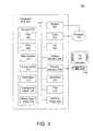
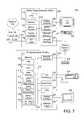
- FIG. 5is a detailed block diagram of a home entertainment system 500 according to an embodiment of the invention.
- the MCX 404may include components similar to those of a standard STB 102 , including a tuner 202 , CA device 204 , display interface 206 , remote interface 208 , CPU 210 , and memory 212 , all of which may be interconnected via a bus 214 .
- the MCX 404may include an MPEG encoder 502 , such as an NECTM ⁇ PD61xx encoder, for encoding or transforming audio/video signals received from the network 103 into media streams for transmission to the PCMC 402 .
- the MCX 404may also include an MPEG decoder 504 for decoding media streams received from the network 103 or the PCMC 402 .
- the MPEG decoder 504may be embodied as a separate MPEG decoding chip or as part of a display interface 206 , such as an ATITM XilleonTM 215s.
- the MPEG encoder 502 and the MPEG decoder 504may be embodied within a single chip or may be implemented using software.
- MPEGis used in a presently preferred embodiment, a variety of other encoding systems may be used within the scope of the invention, such as JPEG, JPEG-LS, H.261, and H.263. Accordingly, the invention should not be construed as being limited to MPEG encoding.
- the MCX 404may additionally include a network interface 506 for communicating with the PCMC 402 over the home network 406 .
- the configuration of the network interface 506will vary depending on the type of network 406 .
- the network interface 506may be embodied as a 10/100 Mbps Ethernet adapter, 802.11b adapter, an IEEE 1394 adapter, or the like.
- the PCMC 402may be implemented using a general purpose personal computer, such as a DellTM DimensionTM 2200. Accordingly, the PCMC 402 may include various standard components similar to those of an advanced STB 302 . For instance, the PCMC 402 may include a display interface 206 for driving a computer monitor 508 , a CPU 210 , a memory 212 , a hard drive 303 , a DVD/CD player 304 , and so forth.
- the PCMC 402may include a network interface 506 for communicating with the MCX 404 over the home network 406 .
- the network interface 506may also be coupled to a modem 408 for communicating with the Internet 108 and/or the broadband network 103 .
- the modem 408may be included within the PCMC 402 , itself, as an add-in board.
- the PCMC 402may include various I/O interfaces 510 for communicating with various external devices.
- the PCMC 402may include I/O interfaces 510 for receiving input from a mouse 512 and/or keyboard 514 .
- the PCMC 402may include various standard I/O interfaces 510 , such as serial ports, parallel ports, USB (universal serial bus) ports, IEEE 1394 (firewire) ports, and the like. All of the components of the PCMC 402 may be interconnected by a bus 214 .
- the memory 212 of the PCMC 402may be configured with various software modules similar to those of the advanced STB 302 .
- the memory 212 of the PCMC 402may include a PVR module 306 , an EPG module 308 , a web browser 310 , an e-mail client 312 , a videophone client 316 , and a media player/editor 318 .
- the memory 212 of the PCMC 402may include an MPEG codec 516 (compressor/decompressor), which may be used to decode MPEG streams received from the MCX 404 as well as to encode MPEG streams to be sent to the MCX 404 .
- MPEG codec 516is depicted as a software component, a hardware implementation may be used within the scope of the invention.
- an add-in cardsuch as the CanopusTM MVR1000TM hardware MPEG-2 encoder, may be provided.
- the memory 212 of the PCMC 402may include an OS 520 for the MCX, such as LinuxTM.
- the MCX 404may boot (i.e., load the OS 520 into memory 212 ) from a copy stored within the PCMC 402 .
- the network interface 506 of the MCX 404may be compatible with the 3ComTM DynamicAccessTM managed PC boot agent or other network boot service. This eliminates the need for the MCX 404 to locally store the MCX OS 520 within a flash memory or hard drive 303 .
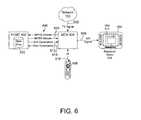
- FIG. 6depicts the flow of data through the system 500 of FIG. 5 .
- a media signal 602such as a TV signal
- the media signal 602may be an analog TV signal, a “digital” cable or satellite TV signal, a Video-on-Demand (VoD) signal, or other transmission.
- VoDVideo-on-Demand
- the MCX 404encodes the media signal 602 into an MPEG stream 604 and sends the MPEG stream 604 via the home network 406 to the PCMC 402 .
- the MCX 404may simply relay the digitally-encoded media signal 602 to the PCMC 402 .
- the MPEG stream 604is recorded or stored in a hard drive 303 , memory, or other digital storage device.
- the MPEG stream 604may be used or manipulated in a variety of ways. For instance, the MPEG stream 604 may be edited using the media player/editor 318 , sent to another subscriber using the videophone client 316 or the e-mail client 312 , indexed for subsequent playback by the PVR module 306 , etc.
- a stored MPEG stream 604is retrieved from the hard drive 303 and transported via the home network 406 to the MCX 404 .
- the retrieved MPEG stream 604may be one that was recorded by the PVR module 306 , edited by the media player/editor 318 , etc.
- the MPEG stream 604is decoded by the MPEG decoder 504 and converted by the display interface 206 into an A/V (audio/video) signal 606 , which may be displayed as rendered video 608 on the TV 104 .
- the PCMC 402may be responsible for creating and updating a graphical user interface (GUI) 610 on the TV 104 .
- GUIgraphical user interface
- the PCMC 402sends GUI commands 612 to the MCX 404 , which are used by the display interface 206 to generate the GUI 610 .
- the GUI commands 612may be embodied, for instance, as low-level VGA (Video Graphics Array) commands which may be directly processed by circuitry within the display interface 206 .
- the GUI commands 612may be graphical primitives understood by a thin-client module (not shown) within the MCX 404 .
- the GUI commands 612may include higher-level data objects, such as graphics and text.
- the GUI commands 612may be encoded into the MPEG stream 604 .
- the GUI 610may provide an interface to various modules within the PCMC 402 , such as the PVR module 306 , EPG module 308 , web browser 310 , e-mail client 312 , videophone client 316 , media player/editor 318 , or the like.
- the GUI 610may display a listing of TV programs recorded by the PVR module 306 and allow a subscriber to select one or more of the TV programs for playback, deletion, etc.
- the GUI 610may display content retrieved by the web browser 310 from the Internet 108 .
- the PCMC 402may be further responsible for receiving input from the remote control 106 and relaying certain user commands 614 or requests to the PCMC 402 .
- the remote control 106may send an IR command 616 to the MCX 404 in response to the user pressing a button.
- the IR command 616is processed by the MCX 404 and, in certain configurations, relayed to the PCMC 402 as a user command 614 .
- the TV signal 602contains a TV program that is scheduled to be recorded by the PVR module 306 of the PCMC 402 .
- the MCX 404encodes the TV signal 602 into an MPEG stream 604 , which is sent to the PCMC 402 where it is stored within the hard drive 303 .
- a subscriberdesires to watch the recorded TV program.
- the subscriberpresses a designated button on the remote control for displaying the GUI 610 on the TV 104 .
- An IR command 616is sent to the MCX 404 , which sends a corresponding user command 614 to the PCMC 402 .
- the PCMC 402generates GUI commands 612 , which are sent to the MCX 404 and rendered as the GUI 610 on the TV 104 .
- the subscriberinitiates a command to display the recorded TV program.
- the PCMCretrieves or reads the appropriate MPEG stream 604 from the hard drive 303 and sends the same to the MCX 404 where it is rendered and displayed on the TV 104 .
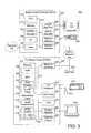
- FIG. 7is a detailed block diagram of a home entertainment system 700 according to an alternative embodiment of the invention.
- the MCX 404may be optionally coupled to a standard STB 102 , such as a MotorolaTM DCT2000TM.
- the standard STB 102is leveraged for its tuner 202 and CA device 204 , eliminating the need for such components within the MCX 404 . Accordingly, the currently-installed base of standard STBs 102 need not be replaced and the overall cost of the MCX 404 is thereby reduced.
- the MCX 404includes a remote tuning controller 702 for controlling the tuning of the STB 102 .
- the remote tuning controller 702simulates a remote control 106 by transmitting appropriate tuning control signals to the STB 102 .
- the remote tuning controller 702may be embodied, for instance, as an IR emitter (e.g., IR BlasterTM), which simulates a remote control 106 by emitting IR commands similar to those of the remote control 106 .
- the remote tuning controllermay include a serial cable and suitable driving hardware for transmitting tuning control signals directly to a serial port of the STB 102 .
- the MotorolaTM DCT2000TMfor example, includes such a serial port for receiving tuning control signals.
- an A/V output 704 of the STB 102is connected to the TV 104 .
- the A/V output 704 of the STB 102is coupled to an A/V input 706 of the MCX 404 .
- the MCX 404receives the same A/V signals that would normally have been received by the TV 104 .
- Various types of A/V connectionsmay be used depending on the capabilities of the STB 102 , e.g., composite video, s-video, component video, stereo audio, optical/coaxial digital audio, RF audio/video, etc.
- FIG. 8depicts the flow of data through the system 700 of FIG. 7 .
- the dataflow of FIG. 8is similar to that of FIG. 6 , except that the TV signal 602 is first received by the STB 102 rather than the MCX 404 .
- the STB 102generates an A/V signal 606 , which is received by the MCX 404 . Thereafter, the A/V signal 606 may be encoded, displayed, etc., as described with reference to FIG. 6 .
- the MCX 404controls the tuning of the STB 102 with tuning command signals, e.g. IR commands 616 .
- tuning command signalse.g. IR commands 616 .
- the STB 102becomes an extension of the MCX 404 , performing tuning and conditional access functions, while the MCX 404 can be reserved for encoding/decoding tasks and interfacing with the PCMC 402 .
- a home entertainment system 900may include any number of MCXs 404 .
- a plurality of MCXs 404may be in communication with a PCMC 402 via a hub 902 or wireless LAN 904 (WLAN).
- Each MCX 404may be coupled to a separate TV 104 and have a separate remote control 106 . Accordingly, an entire household may be serviced by a single PCMC 402 , which would not be possible conventionally with an advanced STB 302 .
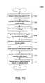
- FIG. 10is a flowchart of a method 1000 within a home entertainment system for processing and displaying media signals 602 .
- a first media signal(e.g., TV signal) 602 is received 1002 at an MCX 404 . Thereafter, the first media signal 602 is encoded 1004 into a first media stream 604 (e.g., MPEG or other data stream), which is sent 1006 via a home network 406 to a PCMC 402 .
- the first media stream 604is then stored 1008 within a storage device (e.g., hard disk) 303 of the PCMC 402 .
- a storage devicee.g., hard disk
- a second media stream 604is retrieved 1010 from the storage device 303 and sent 1012 to the MCX 404 .
- the second media stream 604may include or may be adapted from the first media stream 604 .
- the second media stream 604may be an edited version of the first media stream 604 .
- the second media streamis decoded 1014 and rendered 1016 for display on a television 104 or other display device.
- the present inventionoffers a number of advantages not found in conventional approaches.
- Advanced ITV featuressuch as videoconferencing, personal video recording, and the like, may be provided to subscribers without the inconvenience and expense of replacing currently-installed STBs 102 with advanced STBs 302 .
- existing home PCs, networks, and STBs 102may be leveraged such that the only additional hardware requirement, i.e. an MCX 404 , may be as simple and inexpensive as possible.
- the PCMC 402 and the TV 104need not be collocated, making installation easier and reducing costs.
- multiple TVs 104may be driven simultaneously by a single PCMC 402 , which is not possible with conventional advanced STBs 302 .
Landscapes
- Engineering & Computer Science (AREA)
- Multimedia (AREA)
- Signal Processing (AREA)
- Human Computer Interaction (AREA)
- General Engineering & Computer Science (AREA)
- Two-Way Televisions, Distribution Of Moving Picture Or The Like (AREA)
Abstract
Description
Claims (58)
Priority Applications (1)
| Application Number | Priority Date | Filing Date | Title |
|---|---|---|---|
| US10/259,200US8601514B1 (en) | 2002-09-27 | 2002-09-27 | PC media center and extension device for a home entertainment system |
Applications Claiming Priority (1)
| Application Number | Priority Date | Filing Date | Title |
|---|---|---|---|
| US10/259,200US8601514B1 (en) | 2002-09-27 | 2002-09-27 | PC media center and extension device for a home entertainment system |
Publications (1)
| Publication Number | Publication Date |
|---|---|
| US8601514B1true US8601514B1 (en) | 2013-12-03 |
Family
ID=49640949
Family Applications (1)
| Application Number | Title | Priority Date | Filing Date |
|---|---|---|---|
| US10/259,200Active2026-10-28US8601514B1 (en) | 2002-09-27 | 2002-09-27 | PC media center and extension device for a home entertainment system |
Country Status (1)
| Country | Link |
|---|---|
| US (1) | US8601514B1 (en) |
Cited By (4)
| Publication number | Priority date | Publication date | Assignee | Title |
|---|---|---|---|---|
| US20180063577A1 (en)* | 2016-08-26 | 2018-03-01 | Smart Mobile Broadcasting Technology, Inc. | Distribution device, distribution system, distribution method, electronic machine, play device and receiving program |
| US20180130344A1 (en)* | 2003-12-16 | 2018-05-10 | Universal Electronics Inc. | Relaying key code signals through a remote control device |
| CN110780935A (en)* | 2019-10-31 | 2020-02-11 | 深圳市友华软件科技有限公司 | Synchronous starting method and device for multi-system fusion product |
| US11812091B2 (en) | 2005-08-30 | 2023-11-07 | Maxell, Ltd. | Multimedia player displaying operation panel depending on contents |
Citations (54)
| Publication number | Priority date | Publication date | Assignee | Title |
|---|---|---|---|---|
| US5138649A (en) | 1990-11-16 | 1992-08-11 | General Instrument Corporation | Portable telephone handset with remote control |
| US5335277A (en)* | 1981-11-03 | 1994-08-02 | The Personalized Mass Media Corporation | Signal processing appparatus and methods |
| US5353121A (en) | 1989-10-30 | 1994-10-04 | Starsight Telecast, Inc. | Television schedule system |
| US5673401A (en) | 1995-07-31 | 1997-09-30 | Microsoft Corporation | Systems and methods for a customizable sprite-based graphical user interface |
| US5675390A (en) | 1995-07-17 | 1997-10-07 | Gateway 2000, Inc. | Home entertainment system combining complex processor capability with a high quality display |
| US5884039A (en) | 1993-10-01 | 1999-03-16 | Collaboration Properties, Inc. | System for providing a directory of AV devices and capabilities and call processing such that each participant participates to the extent of capabilities available |
| US5886732A (en) | 1995-11-22 | 1999-03-23 | Samsung Information Systems America | Set-top electronics and network interface unit arrangement |
| US5949328A (en) | 1995-03-03 | 1999-09-07 | Latty; James A. | Apparatus and method for locatable encoding alarms |
| US5987256A (en) | 1997-09-03 | 1999-11-16 | Enreach Technology, Inc. | System and process for object rendering on thin client platforms |
| US5990927A (en) | 1992-12-09 | 1999-11-23 | Discovery Communications, Inc. | Advanced set top terminal for cable television delivery systems |
| US6097441A (en) | 1997-12-31 | 2000-08-01 | Eremote, Inc. | System for dual-display interaction with integrated television and internet content |
| WO2000065429A1 (en) | 1999-04-22 | 2000-11-02 | Nokia Corporation | Method and an arrangement for scrollable cross point navigation in a user interface |
| US6167443A (en)* | 1996-01-22 | 2000-12-26 | Svi Systems, Inc. | Entertainment and information systems and related management networks for a remote video delivery system |
| US6198479B1 (en) | 1997-06-25 | 2001-03-06 | Samsung Electronics Co., Ltd | Home network, browser based, command and control |
| US6202211B1 (en)* | 1998-02-06 | 2001-03-13 | Henry R. Williams, Jr. | Method and apparatus for providing television signals to multiple viewing systems on a network |
| US6289169B1 (en) | 1998-05-07 | 2001-09-11 | Kabushiki Kaisha Toshiba | Apparatus and method of displaying recording |
| US6378000B1 (en) | 1999-04-29 | 2002-04-23 | Mitsubish Electric Research Laboratories, Inc | Address mapping in home entertainment network |
| US20020051083A1 (en) | 2000-05-12 | 2002-05-02 | Shuntaro Aratani | Display apparatus |
| US20020053081A1 (en)* | 2000-10-31 | 2002-05-02 | Digitaldeck, Inc. | Adaptable programming guide for networked devices |
| US20020059625A1 (en)* | 2000-08-30 | 2002-05-16 | Nobukazu Kurauchi | Nonlinear broadcast system |
| US20020057893A1 (en) | 1998-08-11 | 2002-05-16 | Anthony Wood | Digital recording and playback |
| US20020095615A1 (en)* | 2000-10-15 | 2002-07-18 | Hastings Jeffrey S. | Fail safe recovery |
| US20020095689A1 (en)* | 2001-01-12 | 2002-07-18 | Novak Robert E. | Hardware decoding of media streams from multiple sources |
| US6425129B1 (en) | 1999-03-31 | 2002-07-23 | Sony Corporation | Channel preview with rate dependent channel information |
| US20020104090A1 (en) | 2000-08-10 | 2002-08-01 | Stettner Armando Paul | System and method for interactive advertising |
| US6481013B1 (en) | 1998-11-09 | 2002-11-12 | Peracom Networks, Inc. | Entertainment and computer coaxial network and method of distributing signals therethrough |
| US20020174444A1 (en)* | 2001-05-21 | 2002-11-21 | Jean-Marie Gatto | Trusted transactional set-top box |
| US6510152B1 (en) | 1997-12-31 | 2003-01-21 | At&T Corp. | Coaxial cable/twisted pair fed, integrated residence gateway controlled, set-top box |
| US20030066082A1 (en) | 2000-08-30 | 2003-04-03 | Avi Kliger | Home network system and method |
| US20030090524A1 (en) | 2001-11-02 | 2003-05-15 | Tomas Segerberg | Program guide data selection device |
| US20030117440A1 (en) | 2001-12-21 | 2003-06-26 | Hellyar Paul S. | Method and system for switching between multiple computer applications |
| US20030126242A1 (en) | 2001-12-28 | 2003-07-03 | Chang Albert H. | Network boot system and method using remotely-stored, client-specific boot images created from shared, base snapshot image |
| US6590604B1 (en) | 2000-04-07 | 2003-07-08 | Polycom, Inc. | Personal videoconferencing system having distributed processing architecture |
| US20030154485A1 (en)* | 2002-02-12 | 2003-08-14 | Johnson Carolynn Rae | Allocation of recording space per user and application |
| US6622307B1 (en) | 1999-03-26 | 2003-09-16 | Hughes Electronics Corporation | Multiple-room signal distribution system |
| US20030188320A1 (en) | 2002-04-02 | 2003-10-02 | Intervideo, Inc. | Method and system for a distributed digital video recorder |
| US6640239B1 (en) | 1999-11-10 | 2003-10-28 | Garuda Network Corporation | Apparatus and method for intelligent scalable switching network |
| US6678737B1 (en)* | 2000-04-28 | 2004-01-13 | Webtv Networks, Inc. | Home network appliance and method |
| US20040031058A1 (en) | 2002-05-10 | 2004-02-12 | Richard Reisman | Method and apparatus for browsing using alternative linkbases |
| US20040049794A1 (en) | 2000-12-28 | 2004-03-11 | Jiang Shao | Method for managing audiovisual broadcast recordings and associated devices |
| US20040244056A1 (en)* | 2001-02-21 | 2004-12-02 | Lorenz Kim E. | System and method for providing direct, context-sensitive customer support in an interactive television system |
| US20040250273A1 (en) | 2001-04-02 | 2004-12-09 | Bellsouth Intellectual Property Corporation | Digital video broadcast device decoder |
| US20040261099A1 (en)* | 2000-06-21 | 2004-12-23 | Durden George A. | Method for formulating, delivering and managing data concerning programming content and portions thereof |
| US20050028208A1 (en)* | 1998-07-17 | 2005-02-03 | United Video Properties, Inc. | Interactive television program guide with remote access |
| US6889385B1 (en)* | 2000-01-14 | 2005-05-03 | Terayon Communication Systems, Inc | Home network for receiving video-on-demand and other requested programs and services |
| US6909849B1 (en) | 2001-04-12 | 2005-06-21 | Sandra A. Staley | Remote control and flashlight system |
| US20050226324A1 (en)* | 2001-07-31 | 2005-10-13 | He Ouyang | Multiple format video compression |
| US6957396B2 (en) | 2001-10-18 | 2005-10-18 | Sony Corporation | Graphic user interface for digital networks |
| US20050251827A1 (en)* | 1998-07-17 | 2005-11-10 | United Video Properties, Inc. | Interactive television program guide system having multiple devices within a household |
| US6976228B2 (en) | 2001-06-27 | 2005-12-13 | Nokia Corporation | Graphical user interface comprising intersecting scroll bar for selection of content |
| US20060174266A1 (en) | 2001-08-17 | 2006-08-03 | Cyberscan Technology, Inc. | Methods and systems for interactive television |
| US7139983B2 (en) | 2000-04-10 | 2006-11-21 | Hillcrest Laboratories, Inc. | Interactive content guide for television programming |
| US7200857B1 (en) | 2000-06-09 | 2007-04-03 | Scientific-Atlanta, Inc. | Synchronized video-on-demand supplemental commentary |
| US20070288958A1 (en) | 1998-11-30 | 2007-12-13 | United Video Properties, Inc. | Interactive program guide system and method |
- 2002
- 2002-09-27USUS10/259,200patent/US8601514B1/enactiveActive
Patent Citations (55)
| Publication number | Priority date | Publication date | Assignee | Title |
|---|---|---|---|---|
| US5335277A (en)* | 1981-11-03 | 1994-08-02 | The Personalized Mass Media Corporation | Signal processing appparatus and methods |
| US5353121A (en) | 1989-10-30 | 1994-10-04 | Starsight Telecast, Inc. | Television schedule system |
| US5532754A (en) | 1989-10-30 | 1996-07-02 | Starsight Telecast Inc. | Background television schedule system |
| US5138649A (en) | 1990-11-16 | 1992-08-11 | General Instrument Corporation | Portable telephone handset with remote control |
| US5990927A (en) | 1992-12-09 | 1999-11-23 | Discovery Communications, Inc. | Advanced set top terminal for cable television delivery systems |
| US5884039A (en) | 1993-10-01 | 1999-03-16 | Collaboration Properties, Inc. | System for providing a directory of AV devices and capabilities and call processing such that each participant participates to the extent of capabilities available |
| US5949328A (en) | 1995-03-03 | 1999-09-07 | Latty; James A. | Apparatus and method for locatable encoding alarms |
| US5675390A (en) | 1995-07-17 | 1997-10-07 | Gateway 2000, Inc. | Home entertainment system combining complex processor capability with a high quality display |
| US5673401A (en) | 1995-07-31 | 1997-09-30 | Microsoft Corporation | Systems and methods for a customizable sprite-based graphical user interface |
| US5886732A (en) | 1995-11-22 | 1999-03-23 | Samsung Information Systems America | Set-top electronics and network interface unit arrangement |
| US6167443A (en)* | 1996-01-22 | 2000-12-26 | Svi Systems, Inc. | Entertainment and information systems and related management networks for a remote video delivery system |
| US6198479B1 (en) | 1997-06-25 | 2001-03-06 | Samsung Electronics Co., Ltd | Home network, browser based, command and control |
| US5987256A (en) | 1997-09-03 | 1999-11-16 | Enreach Technology, Inc. | System and process for object rendering on thin client platforms |
| US6097441A (en) | 1997-12-31 | 2000-08-01 | Eremote, Inc. | System for dual-display interaction with integrated television and internet content |
| US6510152B1 (en) | 1997-12-31 | 2003-01-21 | At&T Corp. | Coaxial cable/twisted pair fed, integrated residence gateway controlled, set-top box |
| US6202211B1 (en)* | 1998-02-06 | 2001-03-13 | Henry R. Williams, Jr. | Method and apparatus for providing television signals to multiple viewing systems on a network |
| US6289169B1 (en) | 1998-05-07 | 2001-09-11 | Kabushiki Kaisha Toshiba | Apparatus and method of displaying recording |
| US20050251827A1 (en)* | 1998-07-17 | 2005-11-10 | United Video Properties, Inc. | Interactive television program guide system having multiple devices within a household |
| US20050028208A1 (en)* | 1998-07-17 | 2005-02-03 | United Video Properties, Inc. | Interactive television program guide with remote access |
| US20020057893A1 (en) | 1998-08-11 | 2002-05-16 | Anthony Wood | Digital recording and playback |
| US6481013B1 (en) | 1998-11-09 | 2002-11-12 | Peracom Networks, Inc. | Entertainment and computer coaxial network and method of distributing signals therethrough |
| US20070288958A1 (en) | 1998-11-30 | 2007-12-13 | United Video Properties, Inc. | Interactive program guide system and method |
| US6622307B1 (en) | 1999-03-26 | 2003-09-16 | Hughes Electronics Corporation | Multiple-room signal distribution system |
| US6425129B1 (en) | 1999-03-31 | 2002-07-23 | Sony Corporation | Channel preview with rate dependent channel information |
| WO2000065429A1 (en) | 1999-04-22 | 2000-11-02 | Nokia Corporation | Method and an arrangement for scrollable cross point navigation in a user interface |
| US6378000B1 (en) | 1999-04-29 | 2002-04-23 | Mitsubish Electric Research Laboratories, Inc | Address mapping in home entertainment network |
| US6640239B1 (en) | 1999-11-10 | 2003-10-28 | Garuda Network Corporation | Apparatus and method for intelligent scalable switching network |
| US6889385B1 (en)* | 2000-01-14 | 2005-05-03 | Terayon Communication Systems, Inc | Home network for receiving video-on-demand and other requested programs and services |
| US6590604B1 (en) | 2000-04-07 | 2003-07-08 | Polycom, Inc. | Personal videoconferencing system having distributed processing architecture |
| US7139983B2 (en) | 2000-04-10 | 2006-11-21 | Hillcrest Laboratories, Inc. | Interactive content guide for television programming |
| US6678737B1 (en)* | 2000-04-28 | 2004-01-13 | Webtv Networks, Inc. | Home network appliance and method |
| US20020051083A1 (en) | 2000-05-12 | 2002-05-02 | Shuntaro Aratani | Display apparatus |
| US7200857B1 (en) | 2000-06-09 | 2007-04-03 | Scientific-Atlanta, Inc. | Synchronized video-on-demand supplemental commentary |
| US20040261099A1 (en)* | 2000-06-21 | 2004-12-23 | Durden George A. | Method for formulating, delivering and managing data concerning programming content and portions thereof |
| US20020104090A1 (en) | 2000-08-10 | 2002-08-01 | Stettner Armando Paul | System and method for interactive advertising |
| US20030066082A1 (en) | 2000-08-30 | 2003-04-03 | Avi Kliger | Home network system and method |
| US20020059625A1 (en)* | 2000-08-30 | 2002-05-16 | Nobukazu Kurauchi | Nonlinear broadcast system |
| US20020095615A1 (en)* | 2000-10-15 | 2002-07-18 | Hastings Jeffrey S. | Fail safe recovery |
| US20020053081A1 (en)* | 2000-10-31 | 2002-05-02 | Digitaldeck, Inc. | Adaptable programming guide for networked devices |
| US20040049794A1 (en) | 2000-12-28 | 2004-03-11 | Jiang Shao | Method for managing audiovisual broadcast recordings and associated devices |
| US20020095689A1 (en)* | 2001-01-12 | 2002-07-18 | Novak Robert E. | Hardware decoding of media streams from multiple sources |
| US20040244056A1 (en)* | 2001-02-21 | 2004-12-02 | Lorenz Kim E. | System and method for providing direct, context-sensitive customer support in an interactive television system |
| US20040250273A1 (en) | 2001-04-02 | 2004-12-09 | Bellsouth Intellectual Property Corporation | Digital video broadcast device decoder |
| US6909849B1 (en) | 2001-04-12 | 2005-06-21 | Sandra A. Staley | Remote control and flashlight system |
| US20020174444A1 (en)* | 2001-05-21 | 2002-11-21 | Jean-Marie Gatto | Trusted transactional set-top box |
| US6976228B2 (en) | 2001-06-27 | 2005-12-13 | Nokia Corporation | Graphical user interface comprising intersecting scroll bar for selection of content |
| US20050226324A1 (en)* | 2001-07-31 | 2005-10-13 | He Ouyang | Multiple format video compression |
| US20060174266A1 (en) | 2001-08-17 | 2006-08-03 | Cyberscan Technology, Inc. | Methods and systems for interactive television |
| US6957396B2 (en) | 2001-10-18 | 2005-10-18 | Sony Corporation | Graphic user interface for digital networks |
| US20030090524A1 (en) | 2001-11-02 | 2003-05-15 | Tomas Segerberg | Program guide data selection device |
| US20030117440A1 (en) | 2001-12-21 | 2003-06-26 | Hellyar Paul S. | Method and system for switching between multiple computer applications |
| US20030126242A1 (en) | 2001-12-28 | 2003-07-03 | Chang Albert H. | Network boot system and method using remotely-stored, client-specific boot images created from shared, base snapshot image |
| US20030154485A1 (en)* | 2002-02-12 | 2003-08-14 | Johnson Carolynn Rae | Allocation of recording space per user and application |
| US20030188320A1 (en) | 2002-04-02 | 2003-10-02 | Intervideo, Inc. | Method and system for a distributed digital video recorder |
| US20040031058A1 (en) | 2002-05-10 | 2004-02-12 | Richard Reisman | Method and apparatus for browsing using alternative linkbases |
Non-Patent Citations (22)
| Title |
|---|
| Notice of Allowance mailed Mar. 5, 2008, for U.S. Appl. No. 10/260,700, filed Sep. 30, 2002. |
| Office Action mailed Apr. 27, 2009 in U.S. Appl. No. 10/260,740, filed Sep. 30, 2002. |
| Office Action mailed Apr. 3, 2008, for U.S. Appl. No. 10/261,071, filed Sep. 30, 2002. |
| Office Action mailed Aug. 22, 2007 in U.S. Appl. No. 10/260,740, filed Sep. 30, 2002. |
| Office Action mailed Aug. 22, 2007, for U.S. Appl. No. 10/260,700, filed Sep. 30, 2002. |
| Office Action mailed Aug. 22, 2007, for U.S. Appl. No. 10/260,740, filed Sep. 30, 2002. |
| Office action mailed Feb. 22, 2008, for U.S. Appl. No. 10/260,738, filed Sep. 30, 2002. |
| Office Action mailed Feb. 22, 2008, for U.S. Appl. No. 10/260,739, filed Sep. 30, 2002. |
| Office Action mailed Feb. 6, 2008, for U.S. Appl. No. 10/464,826, filed Jun. 18, 2003. |
| Office Action mailed Jan. 11, 2008, for U.S. Appl. No. 10/260,740, filed Sep. 30, 2002. |
| Office Action mailed Mar. 17, 2009 in U.S. Appl. No. 10/260,738, filed Sep. 30, 2002. |
| Office Action mailed Mar. 19, 2009 in U.S. Appl. No. 10/261,071, filed Sep. 30, 2002. |
| Office Action mailed May 29, 2008, for U.S. Appl. No. 10/260,740, filed Sep. 30, 2002. |
| Office Action mailed May 4, 2007, for U.S. Appl. No. 10/261,071, filed Sep. 30, 2002. |
| Office Action mailed Nov. 13, 2008 in U.S. Appl. No. 10/260,740, filed Sep. 30, 2002. |
| Office Action mailed Nov. 14, 2007, for U.S. Appl. No. 10/261,071, filed Sep. 30, 2002. |
| Office Action mailed Nov. 23, 2009 in U.S. Appl. No. 10/260,738, filed Sep. 30, 2002. |
| Office Action mailed Oct. 22, 2009 in U.S. Appl. No. 10/261,071, filed Sep. 30, 2002. |
| Office Action mailed Oct. 3, 2008 in U.S. Appl. No. 10/261,071, filed Sep. 30, 2002. |
| Office Action mailed Sep. 10, 2007, for U.S. Appl. No. 10/464,826, filed Jun. 18, 2003. |
| Office Action mailed Sep. 11, 2008 in U.S. Appl. No. 10/260,738, filed Sep. 30, 2002. |
| Office Action mailed Sep. 30, 2008 in U.S. Appl. No. 10/260,739, filed Sep. 30, 2002. |
Cited By (8)
| Publication number | Priority date | Publication date | Assignee | Title |
|---|---|---|---|---|
| US20180130344A1 (en)* | 2003-12-16 | 2018-05-10 | Universal Electronics Inc. | Relaying key code signals through a remote control device |
| US11812091B2 (en) | 2005-08-30 | 2023-11-07 | Maxell, Ltd. | Multimedia player displaying operation panel depending on contents |
| US11924502B2 (en) | 2005-08-30 | 2024-03-05 | Maxell, Ltd. | Multimedia player displaying operation panel depending on contents |
| US11974007B2 (en) | 2005-08-30 | 2024-04-30 | Maxell, Ltd. | Multimedia player displaying operation panel depending on contents |
| US11974008B2 (en) | 2005-08-30 | 2024-04-30 | Maxell, Ltd. | Multimedia player displaying operation panel depending on contents |
| US12219202B2 (en) | 2005-08-30 | 2025-02-04 | Maxell, Ltd. | Multimedia player displaying operation panel depending on contents |
| US20180063577A1 (en)* | 2016-08-26 | 2018-03-01 | Smart Mobile Broadcasting Technology, Inc. | Distribution device, distribution system, distribution method, electronic machine, play device and receiving program |
| CN110780935A (en)* | 2019-10-31 | 2020-02-11 | 深圳市友华软件科技有限公司 | Synchronous starting method and device for multi-system fusion product |
Similar Documents
| Publication | Publication Date | Title |
|---|---|---|
| US8601507B2 (en) | System and method for focused navigation in a media center/extension device architecture | |
| CA2501865C (en) | Systems and methods for operating a peripheral record/playback device in a networked multimedia system | |
| TW504930B (en) | Personal versatile recorder and method of implementing and using same | |
| US7890975B2 (en) | Data broadcast method | |
| US20020104098A1 (en) | Subscriber class television channel with class member programming | |
| US20030005429A1 (en) | EPG with video previews | |
| US20070107019A1 (en) | Methods and apparatuses for an integrated media device | |
| US20010030959A1 (en) | Data delivery in set-top box | |
| US20020174424A1 (en) | Apparatus and method for providing an indication of program(s) and/or activities | |
| US7571232B2 (en) | Method and apparatus for managing channel information | |
| US9066151B2 (en) | Expanded media content access systems and methods | |
| US8555326B2 (en) | Display device detection of and response to an idle mode of a remote sender device | |
| US20030070181A1 (en) | Interactive TV client device with integrated removable storage system | |
| US20020088002A1 (en) | Transmission of camera image to remote display device | |
| US8141117B1 (en) | PC media center and extension device for interfacing with a personal video recorder through a home network | |
| US8601514B1 (en) | PC media center and extension device for a home entertainment system | |
| US20040258389A1 (en) | Pass through mode for a personal video recorder | |
| US20060263044A1 (en) | Method of providing time shift function in audio/video network and apparatus for the same | |
| KR100669538B1 (en) | Personal broadcasting method and system using personal video recorder | |
| KR100529126B1 (en) | Image service method of pvr | |
| JP2001275063A (en) | Receiving device and system using the same |
Legal Events
| Date | Code | Title | Description |
|---|---|---|---|
| AS | Assignment | Owner name:DIGEO, INC., WASHINGTON Free format text:ASSIGNMENT OF ASSIGNORS INTEREST;ASSIGNORS:KELLUM, JOHN M.;BROADUS, CHARLES R.;SIGNING DATES FROM 20021112 TO 20021119;REEL/FRAME:013541/0340 | |
| AS | Assignment | Owner name:VULCAN VENTURES, INC., WASHINGTON Free format text:ASSIGNMENT OF ASSIGNORS INTEREST;ASSIGNOR:DIGEO, INC.;REEL/FRAME:022309/0016 Effective date:20090220 | |
| AS | Assignment | Owner name:ARRIS GROUP, INC., GEORGIA Free format text:ASSIGNMENT OF ASSIGNORS INTEREST;ASSIGNOR:DIGEO, INC AND VULCAN VENTURES, INC.;REEL/FRAME:026621/0258 Effective date:20090922 | |
| AS | Assignment | Owner name:ARRIS ENTERPRISES, INC., GEORGIA Free format text:MERGER;ASSIGNOR:ARRIS GROUP, INC.;REEL/FRAME:030228/0406 Effective date:20130416 | |
| AS | Assignment | Owner name:BANK OF AMERICA, N.A., AS ADMINISTRATIVE AGENT, IL Free format text:SECURITY AGREEMENT;ASSIGNORS:ARRIS GROUP, INC.;ARRIS ENTERPRISES, INC.;ARRIS SOLUTIONS, INC.;AND OTHERS;REEL/FRAME:030498/0023 Effective date:20130417 Owner name:BANK OF AMERICA, N.A., AS ADMINISTRATIVE AGENT, ILLINOIS Free format text:SECURITY AGREEMENT;ASSIGNORS:ARRIS GROUP, INC.;ARRIS ENTERPRISES, INC.;ARRIS SOLUTIONS, INC.;AND OTHERS;REEL/FRAME:030498/0023 Effective date:20130417 | |
| STCF | Information on status: patent grant | Free format text:PATENTED CASE | |
| AS | Assignment | Owner name:ARRIS ENTERPRISES LLC, PENNSYLVANIA Free format text:CHANGE OF NAME;ASSIGNOR:ARRIS ENTERPRISES INC;REEL/FRAME:041995/0031 Effective date:20151231 | |
| FPAY | Fee payment | Year of fee payment:4 | |
| AS | Assignment | Owner name:ARRIS HOLDINGS CORP. OF ILLINOIS, INC., PENNSYLVAN Free format text:TERMINATION AND RELEASE OF SECURITY INTEREST IN PATENTS;ASSIGNOR:BANK OF AMERICA, N.A., AS ADMINISTRATIVE AGENT;REEL/FRAME:048825/0294 Effective date:20190404 Owner name:GENERAL INSTRUMENT INTERNATIONAL HOLDINGS, INC., P Free format text:TERMINATION AND RELEASE OF SECURITY INTEREST IN PATENTS;ASSIGNOR:BANK OF AMERICA, N.A., AS ADMINISTRATIVE AGENT;REEL/FRAME:048825/0294 Effective date:20190404 Owner name:ACADIA AIC, INC., PENNSYLVANIA Free format text:TERMINATION AND RELEASE OF SECURITY INTEREST IN PATENTS;ASSIGNOR:BANK OF AMERICA, N.A., AS ADMINISTRATIVE AGENT;REEL/FRAME:048825/0294 Effective date:20190404 Owner name:QUANTUM BRIDGE COMMUNICATIONS, INC., PENNSYLVANIA Free format text:TERMINATION AND RELEASE OF SECURITY INTEREST IN PATENTS;ASSIGNOR:BANK OF AMERICA, N.A., AS ADMINISTRATIVE AGENT;REEL/FRAME:048825/0294 Effective date:20190404 Owner name:JERROLD DC RADIO, INC., PENNSYLVANIA Free format text:TERMINATION AND RELEASE OF SECURITY INTEREST IN PATENTS;ASSIGNOR:BANK OF AMERICA, N.A., AS ADMINISTRATIVE AGENT;REEL/FRAME:048825/0294 Effective date:20190404 Owner name:TEXSCAN CORPORATION, PENNSYLVANIA Free format text:TERMINATION AND RELEASE OF SECURITY INTEREST IN PATENTS;ASSIGNOR:BANK OF AMERICA, N.A., AS ADMINISTRATIVE AGENT;REEL/FRAME:048825/0294 Effective date:20190404 Owner name:NEXTLEVEL SYSTEMS (PUERTO RICO), INC., PENNSYLVANI Free format text:TERMINATION AND RELEASE OF SECURITY INTEREST IN PATENTS;ASSIGNOR:BANK OF AMERICA, N.A., AS ADMINISTRATIVE AGENT;REEL/FRAME:048825/0294 Effective date:20190404 Owner name:NETOPIA, INC., PENNSYLVANIA Free format text:TERMINATION AND RELEASE OF SECURITY INTEREST IN PATENTS;ASSIGNOR:BANK OF AMERICA, N.A., AS ADMINISTRATIVE AGENT;REEL/FRAME:048825/0294 Effective date:20190404 Owner name:LEAPSTONE SYSTEMS, INC., PENNSYLVANIA Free format text:TERMINATION AND RELEASE OF SECURITY INTEREST IN PATENTS;ASSIGNOR:BANK OF AMERICA, N.A., AS ADMINISTRATIVE AGENT;REEL/FRAME:048825/0294 Effective date:20190404 Owner name:UCENTRIC SYSTEMS, INC., PENNSYLVANIA Free format text:TERMINATION AND RELEASE OF SECURITY INTEREST IN PATENTS;ASSIGNOR:BANK OF AMERICA, N.A., AS ADMINISTRATIVE AGENT;REEL/FRAME:048825/0294 Effective date:20190404 Owner name:GENERAL INSTRUMENT CORPORATION, PENNSYLVANIA Free format text:TERMINATION AND RELEASE OF SECURITY INTEREST IN PATENTS;ASSIGNOR:BANK OF AMERICA, N.A., AS ADMINISTRATIVE AGENT;REEL/FRAME:048825/0294 Effective date:20190404 Owner name:SETJAM, INC., PENNSYLVANIA Free format text:TERMINATION AND RELEASE OF SECURITY INTEREST IN PATENTS;ASSIGNOR:BANK OF AMERICA, N.A., AS ADMINISTRATIVE AGENT;REEL/FRAME:048825/0294 Effective date:20190404 Owner name:SUNUP DESIGN SYSTEMS, INC., PENNSYLVANIA Free format text:TERMINATION AND RELEASE OF SECURITY INTEREST IN PATENTS;ASSIGNOR:BANK OF AMERICA, N.A., AS ADMINISTRATIVE AGENT;REEL/FRAME:048825/0294 Effective date:20190404 Owner name:GIC INTERNATIONAL CAPITAL LLC, PENNSYLVANIA Free format text:TERMINATION AND RELEASE OF SECURITY INTEREST IN PATENTS;ASSIGNOR:BANK OF AMERICA, N.A., AS ADMINISTRATIVE AGENT;REEL/FRAME:048825/0294 Effective date:20190404 Owner name:POWER GUARD, INC., PENNSYLVANIA Free format text:TERMINATION AND RELEASE OF SECURITY INTEREST IN PATENTS;ASSIGNOR:BANK OF AMERICA, N.A., AS ADMINISTRATIVE AGENT;REEL/FRAME:048825/0294 Effective date:20190404 Owner name:GENERAL INSTRUMENT AUTHORIZATION SERVICES, INC., P Free format text:TERMINATION AND RELEASE OF SECURITY INTEREST IN PATENTS;ASSIGNOR:BANK OF AMERICA, N.A., AS ADMINISTRATIVE AGENT;REEL/FRAME:048825/0294 Effective date:20190404 Owner name:AEROCAST, INC., PENNSYLVANIA Free format text:TERMINATION AND RELEASE OF SECURITY INTEREST IN PATENTS;ASSIGNOR:BANK OF AMERICA, N.A., AS ADMINISTRATIVE AGENT;REEL/FRAME:048825/0294 Effective date:20190404 Owner name:4HOME, INC., PENNSYLVANIA Free format text:TERMINATION AND RELEASE OF SECURITY INTEREST IN PATENTS;ASSIGNOR:BANK OF AMERICA, N.A., AS ADMINISTRATIVE AGENT;REEL/FRAME:048825/0294 Effective date:20190404 Owner name:ARRIS KOREA, INC., PENNSYLVANIA Free format text:TERMINATION AND RELEASE OF SECURITY INTEREST IN PATENTS;ASSIGNOR:BANK OF AMERICA, N.A., AS ADMINISTRATIVE AGENT;REEL/FRAME:048825/0294 Effective date:20190404 Owner name:BIG BAND NETWORKS, INC., PENNSYLVANIA Free format text:TERMINATION AND RELEASE OF SECURITY INTEREST IN PATENTS;ASSIGNOR:BANK OF AMERICA, N.A., AS ADMINISTRATIVE AGENT;REEL/FRAME:048825/0294 Effective date:20190404 Owner name:THE GI REALTY TRUST 1996, PENNSYLVANIA Free format text:TERMINATION AND RELEASE OF SECURITY INTEREST IN PATENTS;ASSIGNOR:BANK OF AMERICA, N.A., AS ADMINISTRATIVE AGENT;REEL/FRAME:048825/0294 Effective date:20190404 Owner name:IMEDIA CORPORATION, PENNSYLVANIA Free format text:TERMINATION AND RELEASE OF SECURITY INTEREST IN PATENTS;ASSIGNOR:BANK OF AMERICA, N.A., AS ADMINISTRATIVE AGENT;REEL/FRAME:048825/0294 Effective date:20190404 Owner name:MODULUS VIDEO, INC., PENNSYLVANIA Free format text:TERMINATION AND RELEASE OF SECURITY INTEREST IN PATENTS;ASSIGNOR:BANK OF AMERICA, N.A., AS ADMINISTRATIVE AGENT;REEL/FRAME:048825/0294 Effective date:20190404 Owner name:ARRIS SOLUTIONS, INC., PENNSYLVANIA Free format text:TERMINATION AND RELEASE OF SECURITY INTEREST IN PATENTS;ASSIGNOR:BANK OF AMERICA, N.A., AS ADMINISTRATIVE AGENT;REEL/FRAME:048825/0294 Effective date:20190404 Owner name:BROADBUS TECHNOLOGIES, INC., PENNSYLVANIA Free format text:TERMINATION AND RELEASE OF SECURITY INTEREST IN PATENTS;ASSIGNOR:BANK OF AMERICA, N.A., AS ADMINISTRATIVE AGENT;REEL/FRAME:048825/0294 Effective date:20190404 Owner name:MOTOROLA WIRELINE NETWORKS, INC., PENNSYLVANIA Free format text:TERMINATION AND RELEASE OF SECURITY INTEREST IN PATENTS;ASSIGNOR:BANK OF AMERICA, N.A., AS ADMINISTRATIVE AGENT;REEL/FRAME:048825/0294 Effective date:20190404 Owner name:GIC INTERNATIONAL HOLDCO LLC, PENNSYLVANIA Free format text:TERMINATION AND RELEASE OF SECURITY INTEREST IN PATENTS;ASSIGNOR:BANK OF AMERICA, N.A., AS ADMINISTRATIVE AGENT;REEL/FRAME:048825/0294 Effective date:20190404 Owner name:ARRIS ENTERPRISES, INC., PENNSYLVANIA Free format text:TERMINATION AND RELEASE OF SECURITY INTEREST IN PATENTS;ASSIGNOR:BANK OF AMERICA, N.A., AS ADMINISTRATIVE AGENT;REEL/FRAME:048825/0294 Effective date:20190404 Owner name:ARRIS GROUP, INC., PENNSYLVANIA Free format text:TERMINATION AND RELEASE OF SECURITY INTEREST IN PATENTS;ASSIGNOR:BANK OF AMERICA, N.A., AS ADMINISTRATIVE AGENT;REEL/FRAME:048825/0294 Effective date:20190404 Owner name:CCE SOFTWARE LLC, PENNSYLVANIA Free format text:TERMINATION AND RELEASE OF SECURITY INTEREST IN PATENTS;ASSIGNOR:BANK OF AMERICA, N.A., AS ADMINISTRATIVE AGENT;REEL/FRAME:048825/0294 Effective date:20190404 Owner name:ARRIS HOLDINGS CORP. OF ILLINOIS, INC., PENNSYLVANIA Free format text:TERMINATION AND RELEASE OF SECURITY INTEREST IN PATENTS;ASSIGNOR:BANK OF AMERICA, N.A., AS ADMINISTRATIVE AGENT;REEL/FRAME:048825/0294 Effective date:20190404 Owner name:GENERAL INSTRUMENT INTERNATIONAL HOLDINGS, INC., PENNSYLVANIA Free format text:TERMINATION AND RELEASE OF SECURITY INTEREST IN PATENTS;ASSIGNOR:BANK OF AMERICA, N.A., AS ADMINISTRATIVE AGENT;REEL/FRAME:048825/0294 Effective date:20190404 Owner name:NEXTLEVEL SYSTEMS (PUERTO RICO), INC., PENNSYLVANIA Free format text:TERMINATION AND RELEASE OF SECURITY INTEREST IN PATENTS;ASSIGNOR:BANK OF AMERICA, N.A., AS ADMINISTRATIVE AGENT;REEL/FRAME:048825/0294 Effective date:20190404 Owner name:GENERAL INSTRUMENT AUTHORIZATION SERVICES, INC., PENNSYLVANIA Free format text:TERMINATION AND RELEASE OF SECURITY INTEREST IN PATENTS;ASSIGNOR:BANK OF AMERICA, N.A., AS ADMINISTRATIVE AGENT;REEL/FRAME:048825/0294 Effective date:20190404 | |
| AS | Assignment | Owner name:ARRIS ENTERPRISES LLC, GEORGIA Free format text:CHANGE OF NAME;ASSIGNOR:ARRIS ENTERPRISES, INC.;REEL/FRAME:049586/0470 Effective date:20151231 | |
| AS | Assignment | Owner name:WILMINGTON TRUST, NATIONAL ASSOCIATION, AS COLLATE Free format text:PATENT SECURITY AGREEMENT;ASSIGNOR:ARRIS ENTERPRISES LLC;REEL/FRAME:049820/0495 Effective date:20190404 Owner name:JPMORGAN CHASE BANK, N.A., NEW YORK Free format text:TERM LOAN SECURITY AGREEMENT;ASSIGNORS:COMMSCOPE, INC. OF NORTH CAROLINA;COMMSCOPE TECHNOLOGIES LLC;ARRIS ENTERPRISES LLC;AND OTHERS;REEL/FRAME:049905/0504 Effective date:20190404 Owner name:JPMORGAN CHASE BANK, N.A., NEW YORK Free format text:ABL SECURITY AGREEMENT;ASSIGNORS:COMMSCOPE, INC. OF NORTH CAROLINA;COMMSCOPE TECHNOLOGIES LLC;ARRIS ENTERPRISES LLC;AND OTHERS;REEL/FRAME:049892/0396 Effective date:20190404 Owner name:WILMINGTON TRUST, NATIONAL ASSOCIATION, AS COLLATERAL AGENT, CONNECTICUT Free format text:PATENT SECURITY AGREEMENT;ASSIGNOR:ARRIS ENTERPRISES LLC;REEL/FRAME:049820/0495 Effective date:20190404 | |
| MAFP | Maintenance fee payment | Free format text:PAYMENT OF MAINTENANCE FEE, 8TH YEAR, LARGE ENTITY (ORIGINAL EVENT CODE: M1552); ENTITY STATUS OF PATENT OWNER: LARGE ENTITY Year of fee payment:8 | |
| AS | Assignment | Owner name:WILMINGTON TRUST, DELAWARE Free format text:SECURITY INTEREST;ASSIGNORS:ARRIS SOLUTIONS, INC.;ARRIS ENTERPRISES LLC;COMMSCOPE TECHNOLOGIES LLC;AND OTHERS;REEL/FRAME:060752/0001 Effective date:20211115 | |
| AS | Assignment | Owner name:APOLLO ADMINISTRATIVE AGENCY LLC, NEW YORK Free format text:SECURITY INTEREST;ASSIGNORS:ARRIS ENTERPRISES LLC;COMMSCOPE TECHNOLOGIES LLC;COMMSCOPE INC., OF NORTH CAROLINA;AND OTHERS;REEL/FRAME:069889/0114 Effective date:20241217 | |
| AS | Assignment | Owner name:RUCKUS WIRELESS, LLC (F/K/A RUCKUS WIRELESS, INC.), NORTH CAROLINA Free format text:RELEASE OF SECURITY INTEREST AT REEL/FRAME 049905/0504;ASSIGNOR:JPMORGAN CHASE BANK, N.A., AS COLLATERAL AGENT;REEL/FRAME:071477/0255 Effective date:20241217 Owner name:COMMSCOPE TECHNOLOGIES LLC, NORTH CAROLINA Free format text:RELEASE OF SECURITY INTEREST AT REEL/FRAME 049905/0504;ASSIGNOR:JPMORGAN CHASE BANK, N.A., AS COLLATERAL AGENT;REEL/FRAME:071477/0255 Effective date:20241217 Owner name:COMMSCOPE, INC. OF NORTH CAROLINA, NORTH CAROLINA Free format text:RELEASE OF SECURITY INTEREST AT REEL/FRAME 049905/0504;ASSIGNOR:JPMORGAN CHASE BANK, N.A., AS COLLATERAL AGENT;REEL/FRAME:071477/0255 Effective date:20241217 Owner name:ARRIS SOLUTIONS, INC., NORTH CAROLINA Free format text:RELEASE OF SECURITY INTEREST AT REEL/FRAME 049905/0504;ASSIGNOR:JPMORGAN CHASE BANK, N.A., AS COLLATERAL AGENT;REEL/FRAME:071477/0255 Effective date:20241217 Owner name:ARRIS TECHNOLOGY, INC., NORTH CAROLINA Free format text:RELEASE OF SECURITY INTEREST AT REEL/FRAME 049905/0504;ASSIGNOR:JPMORGAN CHASE BANK, N.A., AS COLLATERAL AGENT;REEL/FRAME:071477/0255 Effective date:20241217 Owner name:ARRIS ENTERPRISES LLC (F/K/A ARRIS ENTERPRISES, INC.), NORTH CAROLINA Free format text:RELEASE OF SECURITY INTEREST AT REEL/FRAME 049905/0504;ASSIGNOR:JPMORGAN CHASE BANK, N.A., AS COLLATERAL AGENT;REEL/FRAME:071477/0255 Effective date:20241217 | |
| FEPP | Fee payment procedure | Free format text:MAINTENANCE FEE REMINDER MAILED (ORIGINAL EVENT CODE: REM.); ENTITY STATUS OF PATENT OWNER: LARGE ENTITY |