US8600519B2 - Transient voltage/current protection system for electronic circuits associated with implanted leads - Google Patents
Transient voltage/current protection system for electronic circuits associated with implanted leadsDownload PDFInfo
- Publication number
- US8600519B2 US8600519B2US12/497,424US49742409AUS8600519B2US 8600519 B2US8600519 B2US 8600519B2US 49742409 AUS49742409 AUS 49742409AUS 8600519 B2US8600519 B2US 8600519B2
- Authority
- US
- United States
- Prior art keywords
- lead
- circuit
- diode
- lead wire
- electronic circuit
- Prior art date
- Legal status (The legal status is an assumption and is not a legal conclusion. Google has not performed a legal analysis and makes no representation as to the accuracy of the status listed.)
- Expired - Fee Related, expires
Links
Images


Classifications
- H—ELECTRICITY
- H03—ELECTRONIC CIRCUITRY
- H03H—IMPEDANCE NETWORKS, e.g. RESONANT CIRCUITS; RESONATORS
- H03H1/00—Constructional details of impedance networks whose electrical mode of operation is not specified or applicable to more than one type of network
- H03H1/0007—Constructional details of impedance networks whose electrical mode of operation is not specified or applicable to more than one type of network of radio frequency interference filters
- A—HUMAN NECESSITIES
- A61—MEDICAL OR VETERINARY SCIENCE; HYGIENE
- A61N—ELECTROTHERAPY; MAGNETOTHERAPY; RADIATION THERAPY; ULTRASOUND THERAPY
- A61N1/00—Electrotherapy; Circuits therefor
- A61N1/02—Details
- A61N1/08—Arrangements or circuits for monitoring, protecting, controlling or indicating
- A61N1/086—Magnetic resonance imaging [MRI] compatible leads
- A—HUMAN NECESSITIES
- A61—MEDICAL OR VETERINARY SCIENCE; HYGIENE
- A61N—ELECTROTHERAPY; MAGNETOTHERAPY; RADIATION THERAPY; ULTRASOUND THERAPY
- A61N1/00—Electrotherapy; Circuits therefor
- A61N1/18—Applying electric currents by contact electrodes
- A61N1/32—Applying electric currents by contact electrodes alternating or intermittent currents
- A61N1/36—Applying electric currents by contact electrodes alternating or intermittent currents for stimulation
- A61N1/362—Heart stimulators
- A61N1/37—Monitoring; Protecting
- A61N1/3718—Monitoring of or protection against external electromagnetic fields or currents
- A—HUMAN NECESSITIES
- A61—MEDICAL OR VETERINARY SCIENCE; HYGIENE
- A61N—ELECTROTHERAPY; MAGNETOTHERAPY; RADIATION THERAPY; ULTRASOUND THERAPY
- A61N1/00—Electrotherapy; Circuits therefor
- A61N1/18—Applying electric currents by contact electrodes
- A61N1/32—Applying electric currents by contact electrodes alternating or intermittent currents
- A61N1/38—Applying electric currents by contact electrodes alternating or intermittent currents for producing shock effects
- A61N1/39—Heart defibrillators
- A61N1/3925—Monitoring; Protecting
- A—HUMAN NECESSITIES
- A61—MEDICAL OR VETERINARY SCIENCE; HYGIENE
- A61N—ELECTROTHERAPY; MAGNETOTHERAPY; RADIATION THERAPY; ULTRASOUND THERAPY
- A61N1/00—Electrotherapy; Circuits therefor
- A61N1/18—Applying electric currents by contact electrodes
- A61N1/32—Applying electric currents by contact electrodes alternating or intermittent currents
- A61N1/38—Applying electric currents by contact electrodes alternating or intermittent currents for producing shock effects
- A61N1/39—Heart defibrillators
- A61N1/3956—Implantable devices for applying electric shocks to the heart, e.g. for cardioversion
- A61N1/3962—Implantable devices for applying electric shocks to the heart, e.g. for cardioversion in combination with another heart therapy
- A61N1/39624—Pain reduction therapy
- H—ELECTRICITY
- H03—ELECTRONIC CIRCUITRY
- H03H—IMPEDANCE NETWORKS, e.g. RESONANT CIRCUITS; RESONATORS
- H03H7/00—Multiple-port networks comprising only passive electrical elements as network components
- H03H7/01—Frequency selective two-port networks
- H03H7/0107—Non-linear filters
- H—ELECTRICITY
- H03—ELECTRONIC CIRCUITRY
- H03H—IMPEDANCE NETWORKS, e.g. RESONANT CIRCUITS; RESONATORS
- H03H7/00—Multiple-port networks comprising only passive electrical elements as network components
- H03H7/01—Frequency selective two-port networks
- H03H7/17—Structural details of sub-circuits of frequency selective networks
- H03H7/1741—Comprising typical LC combinations, irrespective of presence and location of additional resistors
- H03H7/1758—Series LC in shunt or branch path
- H—ELECTRICITY
- H03—ELECTRONIC CIRCUITRY
- H03H—IMPEDANCE NETWORKS, e.g. RESONANT CIRCUITS; RESONATORS
- H03H7/00—Multiple-port networks comprising only passive electrical elements as network components
- H03H7/01—Frequency selective two-port networks
- H03H7/17—Structural details of sub-circuits of frequency selective networks
- H03H7/1741—Comprising typical LC combinations, irrespective of presence and location of additional resistors
- H03H7/1766—Parallel LC in series path
Definitions
- the present inventionrelates to electronic circuits associated with leads and leadwires disposed within a living body. More particularly, the present invention relates to a transient voltage/surge current protection system wherein a transient voltage suppressor is electrically connected in parallel with an electronic circuit in order to protect the circuit from a surge current which may momentarily develop as a result of, for example, the use of an automatic external defibrillator during a cardiac emergency.
- Implanted leads or implanted leadwiresare associated with a variety of active implantable medical devices (AIMDs), including cardiac pacemakers, implantable cardioverter defibrillators (ICDs), neurostimulators including deep brain stimulators, spinal cord stimulators and other types of pain control stimulators, and the like. Implanted leadwires may also be associated with probes or catheters which are temporarily inserted into the body. Probes and catheters are used for a variety of applications, including mapping of cardiac signals, cancer ablation and the like. In general, implanted leads or leadwires associated with AIMDs or elongated leads associated with probes or catheters have both a proximal end, external of the AIMD, and a distal therapy delivery or sensing end.
- AIMDsactive implantable medical devices
- ICDsimplantable cardioverter defibrillators
- neurostimulatorsincluding deep brain stimulators, spinal cord stimulators and other types of pain control stimulators, and the like.
- Implanted leadwiresmay also be associated with probe
- AEDsAutomatic external defibrillators
- AEDsare now very common and appear in many public places, including government buildings, airports, airplanes, etc.
- AEDsare generally used by trained personnel who will attend to incidents, however many are public access units which can be found in places including corporate and government offices, shopping centers, airports, restaurants, casinos, hotels, sports stadiums, schools and universities, community centers, fitness centers and health clubs.
- AIMDsAn increasing number of patients with AIMDs are undergoing external defibrillation during cardiac emergencies. There have been reports of damage to AIMDs due to use of AEDs during such emergencies. Typically, AIMDs include internal circuit protection devices to protect against these external voltage surges. Defibrillation is the definitive treatment for life-threatening cardiac arrhythmias, ventricular fibrillation and pulseless ventricular tachycardia. Defibrillation consists of delivering a therapeutic dose of electrical energy to the affected heart with a defibrillator device.
- the external defibrillator or AEDproduces a high energy which depolarizes a critical mass of the heart muscle, terminates the arrhythmia, and allows normal sinus rhythm to be re-established by the body's natural pacemaker in the sinoatrial of the heart.
- Defibrillatorscan be external, transvenous or implanted depending on the type of device used.
- External unitsknown as automatic external defibrillators (AEDs) automate the diagnosis of treatable rhythms so that lay responders or bystanders are able to use them successfully with little or, in some cases, no training.
- the nominal delivered pulse from an AEDis 150 joules.
- the nominal energy deliveryis 50 joules.
- a biphasic waveform of 115 joulesis equivalent to a monophasic wave of about 200 joules.
- An AEDcan supply as much as 2000 volts from its high-energy storage capacitors with an 80 maximum peak ampere for a 25-ohm impedance patient.
- a 50-ohm patientwould receive 40 maximum peak amperes (reference: Association for the Advancement of Medical Instrumentation Standards).
- the surge currents induced in an implanted leadwire due to the transient voltage introduced through use of an AEDcould be 2 to 6 amps or even higher.
- lead-based electronic componentsIn order to make AIMDs compatible with medical diagnostic procedures such as magnetic resonance imaging (MRI), a number of lead-based electronic components are being developed. These lead-based components can be bandstop filters, electronic filters, micro-electrical mechanical switches (MEMS), multiplexers, and other types of active electronic filters or switches. See, for example, U.S. Pat. No. 7,363,090 the contents of which are incorporated herein by reference. See also U.S. patent Ser. Nos. 11/558,349, 11/743,000, 11/860,402, 11/930,742, 11/838,035, 11/943,883, 11/943,854, 12/8,489,921, and 61/016,364 the contents all of which are incorporated herein by reference.
- high currentscan be picked up by implanted leads or leadwires. This depends on electrode placement, the physical characteristics of the patient, and also the location of implanted leads or leadwires.
- a transient voltage or high surge currentneed not always come from an external source like an AED.
- an implantable cardioverter defibrillatorsenses abnormal cardiac activity, such as dangerous ventricular arrhythmias. When a dangerous ventricular arrhythmia is detected, the ICD delivers a high voltage shock through leads whose electrodes are in intimate contact or associated with the heart. If the ICD leadwire system has any electronic circuits disposed in its leads, the high voltage shock must pass through said electronic circuit. For example, if a bandstop filter, such as one described in U.S. Pat. No.
- ICD pulsesmay be monophasic or biphasic. Therefore, it is important to protect circuit components placed in implanted leads from both positive and negative polarity voltage which could result in current surges in either direction in the lead. As for the case with an AED, protection of all kinds of lead based electronic circuits is important. This includes not only bandstop filters, but all types of frequency selective impeding or diverting circuits, MEMS switches, electronic switches, multiplexing switches and the like. Such protection is also needed for a wide range of lead based sensors, including oxygen sensors, pressure sensors, general blood gas sensors, artificial valve lead transducers and the like.
- circuit protection devicesfor electrical or electronic circuits that are associated with implanted or implantable leads, leadwires and the like.
- Such circuit protection devicesmust be of such dimension and construction to lend themselves for use with implantable leads, leadwires and the like, and must not interfere with the normal therapy delivery or sensing functions of the implanted leads or leadwires.
- circuit protection devicesmust allow for normal operation of the electrical or electronic circuits disposed in series with the implanted leads or leadwires, and preferably function to divert a surge current around the electrical or electronic circuits in order to bypass the same during a cardiac emergency, for example, a high voltage pulse introduced into the major leadwire system through the use of an AED or an ICD.
- the present inventionfulfills these needs and provides other related advantages.
- the present inventionrelates to a transient voltage/surge current protection system.
- the systemincludes a lead having a proximal end and a distal end disposed within a living body.
- An electronic circuitis associated with the lead between the proximal end and the distal end.
- the transient voltage suppressoris electrically connected in parallel with the electronic circuit.
- the leadmay comprise a probe, a catheter, or a leadwire connected to an active medical device. Further, the lead may either be temporarily or permanently implanted in a human body.
- the electronic circuitcomprises a frequency selective diverter (low impedance) or impeder (high impedance) circuits or combinations thereof.
- a frequency selective diverter or impeder circuitmay comprise an electronic filter. This could be a low pass filter, an L-C trap filter, or a bandstop filter.
- the electronic circuitmay comprise micro electrical-mechanical switches (MEMS), passive electronic switches, multiplexing switches, active electronic switches, or diode switches.
- MEMSmicro electrical-mechanical switches
- the transient voltage suppressormay comprise a diode, a zener diode, a transorb, a surge protector, or varistor components.
- the transient voltage suppressorcomprises back-to-back or bi-directional components.
- the back-to-back componentsmay comprise zener diodes.
- the electronic circuitcomprises a capacitor having a first electrode plate separated from a second electrode plate by a dielectric material.
- the dielectric materialcomprises a varistor dielectric material so that the capacitor itself integrates features of the electronic circuit and the transient voltage suppressor.
- a hermetic containermay be provided in which the electronic circuit and/or the transient voltage suppressor is disposed.
- the leadmay include a therapy delivery or sensing electrode.
- the electronic circuitis closely associated with the therapy delivery or sensing electrode which may comprise a tip electrode and a ring electrode or a neurostimulator.
- the electronic circuit and the transient voltage suppressorcomprise discrete components physically arranged in series, but electrically connected in parallel.
- the electronic circuitcan comprise a discrete capacitor and a discrete inductor physically arranged in series, but electrically connected in parallel.
- the transient voltage suppressorcomprises a first diode physically arranged in series with the capacitor and the inductor, but electrically connected in parallel to each.
- the transient voltage suppressormay also comprise a discrete second diode physically arranged in series with the first diode, the capacitor and the inductor, and electrically connected in parallel to each.
- a second transient voltage suppressormay be disposed adjacent to the proximal end of the lead.
- Such second transient voltage suppressormay comprise a fast-acting switch disposed within an active medical device associated with the lead.
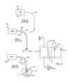
- FIG. 1is a wire-formed diagram of a generic human body showing a number of exemplary implanted medical devices
- FIG. 2is a outline illustration of the neck and torso of a typical patient who has an implanted active implantable medical device (AIMD), showing possible placement of AED paddles on the patient;
- AIMDactive implantable medical device
- FIG. 3is a graph illustrating a typical biphasic shock waveform that may be generated by the AED
- FIG. 4is a schematic illustration of a human heart and a dual chamber, bipolar implanted cardiac pacemaker having leads embodying the present invention implanted in the heart;
- FIG. 5is a schematic illustration similar to FIG. 4 , illustrating an implanted AIMD modified to a single chamber bipolar lead system
- FIG. 6is a schematic illustration of a prior art unipolar AIMD system
- FIG. 7is a schematic illustration of a prior art bipolar AIMD system
- FIG. 8is a schematic illustration similar to FIG. 7 of a prior art bipolar cardiac pacemaker wherein the distal electrodes comprise a ring which floats in the blood pool and a distal tip active electrode;
- FIG. 9is an electrical schematic illustration of a bandstop filter with a transient voltage suppressor electrically connected in parallel in accordance with the present invention and configured for placement in either the distal ring electrode or the distal tip electrode shown in FIG. 8 ;
- FIG. 10is a schematic illustration of a prior art bipolar pacemaker system
- FIG. 11is an enlarged schematic taken generally of the area indicated by the line 11 - 11 of FIG. 10 , illustrating the presence of bandstop filters and their associated transient voltage suppressors (TVS) in series with the distal tip and the distal ring;
- TVStransient voltage suppressors
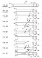
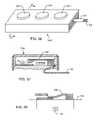
- FIG. 12is a diagrammatic view of a typical probe or catheter
- FIG. 13is a diagrammatic view of the interior of the prober or catheter of FIG. 12 ;
- FIG. 14is an electrical circuit diagram of the structure shown in FIG. 13 , with a general impedance element connected between leadwires;
- FIG. 15is an electrical diagrammatic view similar to FIG. 14 , illustrating a capacitor representing a frequency dependent reactive element between the leadwires;
- FIG. 16is a view similar to FIG. 15 , wherein the general reactance element has been replaced by a capacitor in series with an inductor;
- FIG. 17is a view similar to FIGS. 14-16 , showing the addition of series frequency selective reactances
- FIG. 18is similar to FIG. 13 , showing a low frequency model of the catheter and associated leads described in FIG. 12 ;
- FIG. 19is a view similar to FIGS. 13-18 , illustrating how the distal rings are electrically isolated at a high frequency
- FIG. 20is a view similar to FIGS. 13-19 , showing the addition of series inductor components added to the frequency selective elements 20 ;
- FIG. 21is similar to FIGS. 13-20 , illustrating frequency selective elements which incorporate parallel resonant inductor and capacitor bandstop filters;
- FIG. 22is a partially fragmented sectional view of discoidal feedthrough capacitor having an inductor element to form a parallel bandstop filter circuit and utilizing a varistor dielectric material to impart TVS characteristics to the structure;
- FIG. 23is an electrical schematic illustration of the structure shown in FIG. 22 ;
- FIG. 24is a diagrammatic representation of the human heart, showing epicardial leadwire attachment to the outside of the left ventricle;
- FIG. 25is a cross-sectional view of an epicardial lead embodying a bandstop filter
- FIG. 26is a diagrammatic, side cross-sectional view of the human head showing the placement of a deep brain probe and electrode;
- FIG. 27is an enlarged sectional view of the area designated by line 27 - 27 in FIG. 26 ;
- FIG. 28is an enlarged view taken of the area indicated by line 28 - 28 in FIG. 27 , illustrating use of transient voltage suppressors in parallel with electronic circuits in series with each electrode leadwire;
- FIG. 29is a sectional drawing of a hermetic terminal suitable for incorporation of a transient voltage suppressed bandstop filter of the present invention.
- FIG. 30is a detailed internal component layout wiring diagram of the flex electronic circuit of FIG. 29 ;
- FIG. 31is an elongated electrical schematic of the flex electronic circuit of FIGS. 29 and 30 ;
- FIG. 32is an equivalent electrical schematic of that shown in FIG. 31 ;
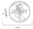
- FIG. 33is an illustration showing the hermetic package of FIG. 29 next to a U.S. penny;
- FIG. 34is an illustration similar to FIG. 33 , illustrating an active fixation tip of an implanted lead that is typical of a cardiac pacemaker;
- FIG. 35is a sectional view of a cardiac active fixation tip electrode
- FIG. 36is a perspective view of a distal electrode pad applicable to a wide variety of neurostimulator and neuromodulator applications
- FIG. 37is a sectional view taken along line 37 - 37 from FIG. 36 , illustrating a MEMS switch in the up-state or open position;
- FIG. 38is a schematic illustration of the structure shown in FIG. 37 , illustrating application of an electrostatic force to cause the MEMS switch to close into a down-state;
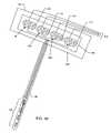
- FIG. 39illustrates a steerable catheter
- FIG. 40is an enlarged fragmented view of a distal end of the steerable catheter of FIG. 39 , taken generally of the area indicated by the line 40 - 40 in FIG. 39 ;
- FIG. 41is an enlarged fragmented sectional view taken generally along the line 41 - 41 on FIG. 40 ;
- FIG. 42is a schematic line diagram for a lead-based sensor incorporating the transient voltage suppressor of the present invention.
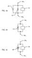
- FIG. 43is an electrical schematic showing two unidirectional transient voltage suppression diodes wired in back-to-back relation, in parallel with an implanted lead electronic circuit;
- FIG. 44is an electrical schematic similar to FIG. 43 , wherein a bi-directional transient voltage suppression diode is illustrated by two mutually opposing avalanche diodes in series with one another;
- FIG. 45is an electrical schematic illustration similar to FIG. 44 , illustrating another type of bi-directional transient voltage suppression diode in parallel with the implanted lead electronic circuit, all in accordance with the present invention.
- the present inventionprovides circuit protection devices for electrical or electronic circuits that are associated with implanted leads.
- the present inventionprovides circuit protection devices such as diodes, zener diodes, Transorbs, surge protectors, varistor components or the like, placed in parallel with electronic circuits in implanted leads to thereby divert harmful current away (around) from sensitive electronic components during an external (AED) or internal (ICD) defibrillation event.
- AEDexternal
- ICDinternal
- FIG. 1is a wire formed diagram of a generic human body showing a number of implanted medical devices 100 A-K.
- 100 Arepresents a family of hearing devices which can include the group of cochlear implants, piezoelectric sound bridge transducers and the like.
- 100 Brepresents a variety of neurostimulators and brain stimulators.
- Neurostimulatorsare used to stimulate the Vagus nerve, for example, to treat epilepsy, obesity and depression.
- Brain stimulatorsare pacemaker-like devices and include electrodes implanted deep into the brain for sensing the onset of the seizure and also providing electrical stimulation to brain tissue to prevent the seizure from actually occurring.
- the leadwires associated with a deep brain stimulatorare often placed using real time MRI imaging. Most commonly such leadwires are placed during real time MRI.
- 100 Cshows a cardiac pacemaker which is well-known in the art.
- 100 Dincludes the family of left ventricular assist devices (LVAD's), and artificial hearts, including the recently introduced artificial heart known as the Abiocor.
- 100 Eincludes an entire family of drug pumps which can be used for dispensing of insulin, chemotherapy drugs, pain medications and the like. Insulin pumps are evolving from passive devices to ones that have sensors and closed loop systems. That is, real time monitoring of blood sugar levels will occur. These devices tend to be more sensitive to EMI than passive pumps that have no sense circuitry or externally implanted leadwires.
- 100 Fincludes a variety of bone growth stimulators for rapid healing of fractures.
- 100 Gincludes urinary incontinence devices.
- 100 Hincludes the family of pain relief spinal cord stimulators and anti-tremor stimulators.
- 100 Halso includes an entire family of other types of neurostimulators used to block pain.
- 100 Iincludes a family of implantable cardioverter defibrillators (ICD) devices and also includes the family of congestive heart failure devices (CHF). This is also known in the art as cardio resynchronization therapy devices, otherwise known as CRT devices.
- 100 Jillustrates an externally worn pack. This pack could be an external insulin pump, an external drug pump, an external neurostimulator or even a ventricular assist device.
- 100 Killustrates the insertion of an external probe or catheter. These probes can be inserted into the femoral artery, for example, or in any other number of locations in the human body.
- FIG. 2is an outline drawing of the neck and torso of a typical patient who has an active implanted medical device (AIMD).
- the AIMDis a pacemaker 100 C.
- the pacemaker 100 Chas an implanted lead 102 which is directed to a distal electrode 104 which, in this case, would be typically implanted into the right ventricle of the patient's heart.
- the pacemaker 100 Ctypically does sensing and also provides pacing pulses in order that the heart can properly beat.
- emergency personnelcould place the two electrode paddles 106 and 108 of an automatic external defibrillator (AED) 110 as shown.
- AEDautomatic external defibrillator
- the implant location for the pacemaker 100 C shown in FIG. 2is not the preferred location.
- a pacemaker 100 C or ICD 100 Iis preferrably placed in the left pectoral pocket where the currents induced into lead 102 by an AED 110 would be lessened.
- FIG. 3shows a typical biphasic shock waveform where the AED voltage will vary from +2000 to ⁇ 2000 volts.
- the timing of the pulsescan vary greatly from one AED manufacturer to another.
- the positive going pulsewould have a pulse width of 20 milliseconds.
- the negative pulsewould also have a duration of approximately 20 milliseconds.
- the biphasic shock waveform of FIG. 3could also represent the output pulse from an ICD.
- the voltageis typically lower (typically around 800 volts) because the implanted leads are directly connected to heart tissue.
- the AEDhas to provide higher energy since it is shocking through the chest wall, pectoral muscles and so forth. Therefore, an ICD is more efficient with its direct connection.
- the transient voltagecan result in very high surge currents which can be very damaging to active or passive lead-based electronic circuits.
- FIG. 4shows the right atrium 112 and right ventricle 114 of a typical human heart 116 .
- a dual chamber bipolar implanted cardiac pacemaker 100 Cis shown which has a connector block 118 for convenient plugging in of implanted leads 102 and 102 .
- these connector blocks 118are designated by ISO Standards IS-1, DF-1 or IS-4.
- a lead 102is directed to the right atrium 112 and is a bipolar lead. At its distal end, it has a distal ring electrode 120 and a distal tip electrode 122 .
- Another lead 102is directed through epicardial placement into the right ventricle 114 .
- bipolar leadwhich terminates in a ring electrode 120 ′ and a tip electrode 122 ′ as shown.
- a biphasic shockis applied to the patient's skin via an AED 110 , current loops are set up as energy is delivered to tissue.
- the current I Wwould flow as shown and then have a return path I T , I T ′, I T ′′, and I T ′′′ back to the conductive housing 124 which is typically conductive of the AIMD. It is the current I W that is of concern, particularly when there are electronic components installed anywhere within the leadwire system 102 or 102 ′ or in association with the distal tip or distal ring electrodes 120 , 120 ′ or 122 , 122 ′.
- FIG. 4also shows an optional switch arrangement 126 and 126 ′ which is internal to the housing 124 of the AIMD 100 C.
- These fast acting electronic switcheswould be in series with the internal electronics 128 of the AIMD. In this way, during an external defibrillation event, these switches 126 , 126 ′ would rapidly and momentarily open until the high voltage pulse from the AED had dissipated. The switches 126 , 126 ′ would then reclose so that the AIMD, such as a cardiac pacemaker, could resume its normal pacing and sensing functions.
- the impedance of the leadwire loopis raised significantly. This acts as a current limiter, not only to the internal sensitive electronic circuits 128 of the AIMD, but also would automatically limit the current that would flow in an implanted leadwire, such as the leads 102 and 102 ′.
- FIG. 5is similar to FIG. 4 in that there is an implanted AIMD, such as a cardiac pacemaker 100 C, but it has been modified to show the present invention in a single chamber bipolar lead system wherein both the ring electrode 120 ′ and the tip electrode 122 ′ are in the right ventricle 114 .
- FIG. 5shows only a blow up of lead 102 ′.
- Implanted leadwirescan typically be of a bifiler or a coaxial nature. In either event, there are two leadwires 130 and 130 ′ leading into the right ventricle 114 , one feeding the tip electrode 122 ′ which makes contact with myocardial tissue, and another feeding the ring electrode 120 ′, which floats in the blood pool.
- a transient voltage suppressor (TVS) 134has been electrically connected in parallel with the electronic circuit 132 .
- the transient voltage suppressor 134would look like a short (or a very low impedance) thereby diverting the bulk of this externally induced defibrillation current around the sensitive electronic circuit or passive filter components 132 . In this way, the transient voltage suppressor or suppression circuit 134 effectively protects the lead-based electronic circuit 132 from current damage that could be caused by application of an AED.
- the AIMDcould also be an ICD 100 I.
- the ICDwill deliver a high voltage monophasic or biphasic waveform. This is required to defibrillate a heart which is undergoing a dangerous arrhythmia, such as ventricular fibrillation.
- the leadwire system of FIG. 5embodies a bandstop filter electronic circuit 132 in order to make the AIMD and its associated leads MRI compatible, then the defibrillation pulse, as illustrated in FIG. 3 , would have to pass through the bandstop filter 132 in order to properly defibrillate the heart.
- the defibrillation currentwould have to pass through the inductor of the bandstop filter.
- the wiring of the inductormust be very small so that it can pass through the venous system of the heart. Accordingly, it is not capable of handling extremely high currents such as those that would be produced by an ICD. ICD currents can, for short periods of time, exceed 10 or 25 amperes.
- the transient voltage suppressor 134 protection circuitsbe used to bypass lead based electronic circuits during internal ICD high voltage shocks as well as bypass extraneous shocks from AEDs.
- the transient voltage suppressor 134 protection circuitbe of fast-acting diodes or the like so that an ICD defibrillation pulse waveform is not distorted.
- FIG. 6is a line drawing representation of a unipolar AIMD system 100 . It consists of a generally hermetically enclosed housing 124 in which electronic circuits for tissue stimulation and/or sensing are housed. A unipolar lead 102 is shown connected to a distal electrode 136 .
- FIG. 7illustrates a very similar system, but in this case, is bipolar.
- FIG. 8is an illustration of a bipolar cardiac pacemaker 100 C wherein the distal electrodes consist of a ring 120 ′ which floats in the blood pool and a distal tip active electrode 122 ′.
- the distal electrode tip 122 ′is either a passive tip or an active fixation tip.
- the active fixation tipwould employ a screw-type helix for affixing said distal electrode tip into myocardial tissue.
- FIG. 9illustrates a bandstop filter 138 which is designed to be placed either adjacent to the distal ring electrode 120 ′ or the distal tip electrode 122 ′ of FIG. 8 .
- the bandstop filter 138which is one type of the electric circuit 132 described previously, consists of parallel inductor 140 and capacitor 142 elements. At resonance, the bandstop filter 138 tends to form a very high impedance. This is more fully described in U.S. Pat. No. 7,373,090. Further description of bandstop filters for attenuating currents in an AIMD patient that is exposed to magnetic resonance imaging are described by in U.S. Patent Publication No. US 2007-0112398 A1; U.S. Patent Publication No. US 2008-0071313 A1; U.S.
- a transient voltage suppressor 134 of the present inventioncomprises parallel back-to-back fast-acting zener diodes 144 and 144 ′ in parallel with the bandstop filter 138 elements.
- FIG. 10illustrates a prior art bipolar pacemaker 100 C system illustrating coaxial leadwires 130 and 130 ′ which terminate in a distal ring 120 and distal tip 122 .
- the distal tip 122is either affixed or is in intimate contact with myocardial or epicardial tissue.
- FIG. 11is an enlarged schematic taken generally of the area indicated by line 11 - 11 from FIG. 10 , and illustrates the presence of a bandstop filter 138 in series with the distal tip electrode 122 and the distal ring electrode 120 in order to provide a high impedance at a selected frequency, such as the RF pulsed frequency of a particular MRI system.
- a selected frequencysuch as the RF pulsed frequency of a particular MRI system.
- the parallel inductor L and capacitor Cwould be designed to resonate at 64 MHz.
- a transient voltage suppressor (TVS) 134Also shown in parallel with the bandstop filter elements L and C is a transient voltage suppressor (TVS) 134 .
- the transient voltage suppressor 134could consist of back-to-back zener diodes as previously described in connection with FIG. 9 , or it could consist of varistor material, or other types of transient voltage suppressors.
- FIGS. 12 through 21illustrate a family of frequency selective passive electronic circuits 132 which can be used either as high frequency diverters or high frequency impeding elements.
- FIG. 12is a diagrammatic view of a typical prior art device 146 such as a probe or catheter.
- a probe or catheterThere are two leadwires 130 and 130 ′ which thread through the center of the illustrative probe or catheter 146 and terminate respectively in a corresponding pair of distal conductive electrode rings 148 and 150 .
- Leadwires 130 and 130 ′are electrically insulated from each other and also electrically insulated from any metallic structures located within the catheter body. There can be any number of leads in actual probes and catheters.
- the overall catheter bodyis generally flexible and is made of biocompatible materials, which also have specific thermal properties. In addition to flexibility, probes and catheters 146 are typically steerable. It is well known that a push-pull wire (not shown in FIG.
- probes and catheterscan be run down the center of the catheter or probe in a lumen and then be attached to a catheter handle or pistol grip or other device so that the physician can carefully steer or thread the probe or catheter through the torturous path of the venous system, even into the ventricles of the heart.
- probes and cathetersfor example, can be used for electrical mapping inside of a heart chamber, or for application of RF energy for ablation, which is used to treat certain cardiac arrhythmias. Probes and catheters have wide application to a variety of other medical applications. There are also combined catheters that can do electrical mapping and can also perform RF ablation.
- FIG. 13is a schematic illustration showing the leadwires 130 and 130 ′ of FIG. 12 , which are routed to the two distal electrodes 148 and 150 .
- FIG. 14shows the electrical schematic of FIG. 13 with a general frequency selective impedance element 152 connected between leadwires 130 and 130 ′.
- the impedance element 152can consist of a number of frequency selective elements as will be further described.
- the first conductive leadwire 130is electrically coupled to the first electrode 148
- the second conductive leadwire 130 ′is electrically coupled to the second electrode 150
- the frequency dependent reactive element 152electrically couples the first and second leadwires 130 and 130 ′ such that high frequency energy is conducted between the first leadwire 130 and the second leadwire 130 ′.
- the frequency dependent reactive element 152tends to be electrically invisible (i.e., a very high impedance) at selected frequencies.
- the reactive elementis desirably selective such that it would not attenuate, for example, low frequency biological signals or RF ablation pulses.
- this frequency reactive element 152would look more like a short circuit. This would have the effect of sending the energy induced into the leadwires 130 and 130 ′ by the MRI RF field back into the catheter body itself into which the leadwires are embedded.
- FIG. 15shows a capacitor 142 which represents one form of the frequency dependent reactive element 152 previously described in connection with FIG. 14 .
- the reactive elementcomprises a simple capacitor connected between the first conductor or leadwire 130 and the second conductor or leadwire 130 ′ and will have a variable impedance vs. frequency.
- X C1/(2 ⁇ fc).
- the capacitive reactancedrops to a very low number (essentially a short circuit).
- thisdiverts and prevents the RF energy from reaching the distal ring electrodes 148 and 150 and being undesirably dissipated as heat into body tissue.
- the impedance element 152thereby diverts the high frequency RF energy back into the leadwires 130 and 130 ′.
- the frequency dependent reactive element 152which may comprise a capacitor 142 as shown in FIG. 15 , forms a diversion circuit such that high frequency energy is diverted away from the distal electrodes 148 and 150 along the leadwires 130 and 130 ′ to a point that is distant from the electrodes, at which point the energy is converted to heat.
- FIG. 16shows an even more efficient way of diverting high frequency energy away from the electrode and accomplishing the same objective.
- the general reactance element 152 described in connection with FIG. 14is shown in FIG. 16 to comprise the capacitor 142 in series with an inductor 140 to form an L-C trap electronic circuit 132 .
- the frequency of resonanceis given by the equation
- f r1 2 ⁇ ⁇ ⁇ LC , wherein f r is the frequency of resonance in Hertz, L is the inductance in henries, and C is the capacitance in farads.
- FIG. 17illustrates any of the aforementioned frequency dependent impedance elements 152 with the addition of series frequency selective reactances 154 and 154 ′.
- the addition of series impedancefurther impedes or blocks the flow of high frequency MRI induced currents to the ring electrodes 148 and 150 as will be more fully described in connection with the following drawings.
- FIG. 18is the low frequency model of FIG. 14 , 15 or 16 .
- FIG. 18is identical to FIG. 13 , in that, once again it shows the electrical leadwires 130 and 130 ′ connected to the distal ring electrodes 148 and 150 of the probe or catheter 146 .
- the frequency reactive impedance elements 152disappear because at low frequency their impedances approach infinity.
- leads in a probe or catheterare electrically equivalent to leads used for cardiac pacemakers, implantable cardioverter defibrillators, neurostimulators and the like.
- U.S. Pat. No. 7,363,090the contents of which are incorporated herein.
- any discussion related to probes or cathetersapply equally to leadwires for all active implantable medical devices as described in FIG. 1 , and vice versa.
- FIG. 18this is also the low frequency model of the circuits shown in FIG. 17 .
- the frequency selective or reactive component 152tends to look like a very high or infinite impedance.
- the series reactive or frequency variable elements 154 at low frequencytend to look like a very low impedance or short circuit. Accordingly, they all tend to disappear as shown in FIG. 18 .
- FIG. 19is a high frequency model that illustrates how the distal electrodes or rings 148 and 150 are electrically isolated at high frequency by shorting leadwires 130 and 130 ′ at location 156 .
- shorting or current divertingcould be accomplished by a series resonant L-C trap circuit.
- FIG. 19also shows the electrodes 148 and 150 as cut or disconnected and electrically isolated from the rest of the circuit. This is because at very high frequency series selective frequency (reactive) elements 154 tend to look like a very high impedance or an open circuit.
- reactive elements 152 and 154 acting cooperativelyreactive element 152 diverts the high frequency energy while at the same time reactive elements 154 impede the high frequency RF energy. Accordingly, in the ideal case, the equivalent circuit of FIG. 19 is achieved.
- the high frequency MRI RF energycannot reach the distal ring electrodes 148 , 150 and cause undesirable heating at that critical tissue interface location.
- FIG. 20shows any of the previously described diverting frequency selective elements 152 in combination with series reactance components 154 ′ shown in the form of a pair of inductors.
- the frequency term (f)is in the numerator. Accordingly, as the frequency increases, the reactance (ohms) of the inductors also increases. When the frequency is very high (such as 64 MHz) then the reactance in ohms becomes extremely high (ideally approaches infinity and cuts off the electrodes).
- the line-to-line selective impedance element 152diverts high frequency energy back into leadwires 130 and 130 ′ while at the same time the series inductors 154 ′ impede (or cut-off) high frequency energy.
- the line-to-line element 152is a capacitor 142 as shown in FIG.
- FIG. 15describes what is known in the prior art as an L section low pass filter, wherein the capacitor 142 electrically cooperates with the inductors 154 ′ ( FIG. 20 ) to form a 2-element low pass filter.
- a low pass filterallows low frequencies such as biological signals to pass to and from the distal electrodes freely without attenuation while at the same time provides a high degree of attenuation to undesirable high frequency energy.
- FIG. 15describes a single element low pass filter
- FIG. 20describes a 2-element or L-section low pass filter.
- any number of inductor and capacitor combinationscan be used for low pass filters, including 3-element Pi or T circuits, LL, 5-element or even “n” element filters.
- FIG. 21offers an even greater performance improvement over that described in connection with FIG. 20 .
- modified frequency selective elements 154 ′′each incorporate a parallel resonant inductor and capacitor which is also known in the industry as a bandstop filter 138 .
- the L-C components for each of the reactive elements 154 ′′are carefully chosen such that each of the bandstop filters is resonant, for example, at the pulsed resonant frequency of an MRI scanner.
- the pulsed resonant frequency of an MR scanneris given by the Lamor equation wherein the RF pulsed frequency in megahertz is equal to 42.56 times the static field strength. For example, for a popular 1.5 Tesla scanner, the RF pulsed frequency is 64 MHz.
- Common MR scanners that are either in use or in development today along with their RF pulsed frequenciesinclude: 0.5 Tesla-21 MHz; 1.5 Tesla-64 MHz; 3 Tesla-128 MHz; 4 Tesla-170 MHz; 5 Tesla-213 MHz; 7 Tesla-300 MHz; 8 Tesla-340 MHz; and 9.4 Tesla-400 MHz.
- bandstop filters 154 ′′ ( 138 )are resonant at any one of these RF pulsed frequencies, then these elements tend to look like an open circuit which impedes the flow of RF current to distal electrodes.
- three separate bandstop filter elements in parallelmay comprise the reactive elements 154 ( FIG. 17 ).
- each of thesewould have their L and C components carefully selected so that they would be resonant at different frequencies.
- the three bandstop filterswould be resonant respectively at 64 MHz, at 128 MHz, and at 170 MHz.
- the resonant frequencies of the bandstop filter elementscould be selected such that they are resonant at the operating frequency of other emitters that the patient may encounter such as diathermy and the like.
- FIG. 22illustrates a discoidal feedthrough capacitor 158 which also has an inductor element 140 .
- Thisforms the parallel bandstop filter circuit 138 as shown in FIG. 9 consisting of a capacitor in parallel with an inductor.
- the feedthrough capacitor 158 of FIG. 22includes a varistor dielectric material 160 , such as metal-oxide based ceramic.
- This varistor dielectric material 160may be similar to materials used in multi-layer ZnO varistors, such as the TransguardTM voltage suppressors are available from AVX Corporation of Myrtle Beach, S.C.
- FIG. 22this is a cross-section of a typical unipolar feedthrough capacitor.
- the active electrode plates 162are connected to internal metallization 166 at the feedthrough hole.
- the ground electrode plates 164are connected to external metallization 168 .
- the inductor 140is connected from one end of the capacitor 158 to the other which places the inductive element in parallel with the capacitive element, forming a bandstop filter 138 .
- the active electrode plates 162are separated from the ground electrode plates 164 by the varistor dielectric material 160 .
- the dielectric material 160When low voltage is applied to the capacitor 158 , the dielectric material 160 has a fairly high resistivity and a relatively high dielectric constant. Accordingly, one can tune the capacitor 158 in accordance with the principles of bandstop filters as described in U.S. 2007/0112398. However, when a high voltage appears across the varistor dielectric material 160 , it tends to go to a very low impedance or short circuit. This allows it to pass very high surge currents without damage to the inductor element 140 in accordance with the present invention.
- a capacitance Cis formed between the electrode plates.
- a variable resistor (varistor) R Vis shown.
- the inductor L ( 140 )is shown in parallel with the capacitor element C.
- the capacitor's varistor dielectric 160tends to be very conductive, which acts as a transient voltage suppressor 134 in accordance with the present invention. This is an important illustration of a way in which transient voltage suppression characteristics can be integrated directly into the design of the electronic circuit 132 .
- FIG. 24is taken from FIG. 3 of U.S. Patent Publication No. US 2008-0132987 A1. Shown is a line diagram of the heart 116 showing the coronary sinus 172 and the great cardiac vein 174 . Also shown is the area outside of the left ventricle 176 . Shown is an epicardial lead 102 that is connected to a sutureless or sutured distal tip epicardial bipolar electrode 178 .
- FIG. 25is a sectional view along line 25 - 25 from FIG. 24 and shows a novel bandstop filter 138 arrangement incorporating the novel feedthrough capacitor 158 and parallel inductor 140 of FIG. 22 . Also incorporated are the transient voltage suppressor formed by using varistor dielectrics 160 .
- FIGS. 26 and 27are taken from FIGS. 13 and 14 of U.S. Patent Publication No. US 2008-0132987 A1.
- a deep brain electrode 180that is placed in a burr hole 182 drilled in the skull 184 .
- the distal electrodes 136are placed precisely in brain tissue so that they can perform the correct neurostimulation or neuromodulation function.
- Leads 102are routed up the back of the neck and are connected to the deep brain electrode(s) 180 .
- the lead 102is routed down typically into the pectoral region of the chest where an AIMD may be implanted (not shown).
- FIG. 27is an enlarged view of the area indicated by the line 27 - 27 from FIG. 26 .
- the deep brain electrode(s) 180consists of a leadwire bundle 102 which is connected to a generally encapsulated or hermetically sealed electronics module 186 .
- the electronics module 186can be placed within the skull 184 or subdural (not shown).
- the distal electrodes 136are implanted deeply into brain tissue 188 .
- FIG. 28is a schematic illustration of the wiring and electronic components within the area indicated by line 28 - 28 of FIG. 27 .
- Shownis an electronic circuit board 190 which is embedded within the electronics module 186 .
- bandstop filters 138 - 138 ′′′consisting of an inductor L in parallel with a capacitor C.
- a transient voltage suppressor TVS 134which is in parallel with each one of the bandstop filter circuits 138 - 138 ′′′. This provides protection against transient voltage events.
- AED paddleswould not be placed, obviously, on the human head.
- the AIMD for the deep brain stimulatorcould be implanted in the pectoral region of a patient's chest.
- the implanted leadscould pick up transient voltages or high current surges. Therefore protection of the deep brain stimulator electronics module 186 from high voltage transients is equally important as it would be for cardiac a pacemaker. This is particularly important if the inductor and capacitor resonator elements were of delicate MEMS type structures.
- FIG. 29is a sectional drawing of a hermetic terminal 192 suitable for incorporation of the novel transient voltage suppressed bandstop filter of the present invention.
- leadwires 130 A and 130 Bthat enter in and exit the hermetic housing 194 .
- the housing 194would be of a suitable biocompatible material such as a ceramic, titanium or other precious metal.
- Insulators 196 A and 196 Bare shown which provide a hermetic seal between the hermetic housing 194 and the leadwires 130 A and 130 B .
- Hermetic insulator 196 A and 196 Bcan be installed either by gold brazed preforms or by prior art compression or fusion glass sealing techniques.
- FIG. 30is a detailed internal component layout wiring diagram of the flex electronic circuit 132 of FIG. 29 . If one follows the circuit traces carefully, one will see that the capacitor 142 and the inductor 140 are wired in parallel along with diodes 144 and 144 ′. This is better understood by referring to FIG. 31 which is a schematic of the flex electronic circuit 132 of FIGS. 29 and 30 . The equivalent electrical schematic of FIG. 31 is shown in FIG. 32 . FIGS. 31 and 32 make it clear that the inductor 140 , the capacitor 142 , and the diodes 144 and 144 ′ are all in parallel. This forms a bandstop filter 138 with back-to-back transient voltage protection diodes ( 134 ) in accordance with the present invention.
- FIG. 33shows the hermetic package 192 of FIG. 29 next to a U.S. penny. One can see how small the hermetic package 192 really is.
- FIG. 34illustrates an active fixation tip 200 of an implanted lead 102 that is typical of a cardiac pacemaker.
- the electrode helix tip 200is designed to be screwed into myocardial tissue. This is also shown in relation to a U.S. penny.
- the active fixation tip 200may also incorporate the novel hermetically sealed bandstop filter 138 and parallel transient voltage suppressor 134 in accordance with the present invention. This is more clearly illustrated in FIG. 35 , which is a sectional view taken from line 35 - 35 of FIG. 34 of the active electrode fixation tip 200 .
- the helix tip 200which is attached to the bandstop filter assembly 138 , consists of a parallel inductor and capacitor along with a transient voltage suppressor 134 of the present invention. This makes the lead system not only MRI compatible, but also compatible with either internal high voltage shocks from an ICD or external high voltage shocks from an AED.
- FIG. 36is taken from FIG. 22 of U.S. Patent Application No. 61/016,364. Shown is a neurostimulation electrode assembly 202 that would be typically used in a spinal cord stimulator or other type of neurostimulator application. Shown are three electrodes 204 , 204 ′ and 204 ′′. A leadwire bundle 102 from the AIMD is also shown.
- FIG. 37is an enlarged section taken underneath the electrode pad 204 taken from FIG. 36 ( 204 ′ and 204 ′′ are similar). Shown is a MEMS switch 206 in the up state or open position. Application of an electrostatic force causes the MEMS switch 206 to close into the down state as illustrated in FIG. 38 . Also shown in FIG. 38 is a transient voltage suppressor 134 of the present invention which would be in parallel with the MEMS switch 206 . This would protect the relatively sensitive MEMS device from transient voltage/surge current events such as those from AEDs.
- the MEMS switch 206is a very delicate electronic switch which is used to make the neurostimulation electrodes 466 204 - 204 ′′ safe during MRI procedures.
- the MEMs switchwould open and these electrodes would be disconnected from the associated elongated leadwires 130 which run to the AIMD (not shown).
- the MEMs switchesare closed.
- Stimulation currentsfor example, those for a spinal cord stimulator, are only a few micro-amps or milliamperes. Accordingly, the MEMS switch 206 can be made of very small and delicate foil-type materials.
- the presence of the transient voltage suppressor 134 of the present inventionbypasses such defibrillation currents thereby protecting the MEMS switch 206 from burning out. This is particularly important when it's in its normal closed state or down state (delivering therapy).
- FIG. 39shows a steerable catheter 142 , which is typically used for a variety of applications including RF or cryo-ablation, cardiac mapping and many other purposes.
- RF ablationinclude treatment for atrial fibrillation, nephrotic conditions, liver, brain, cancers and the like. This would enable stereotactic ablation of certain lesions within the lung.
- An emerging fieldis the entire field of using ablation to treat various ventricular arrhythmias, including ventricular tachycardia.
- the illustrated catheter 142is meant to be representative of all types of catheters or probes which can be inserted into the venous system or other areas of the human body.
- the catheter 142has a tip 208 and an adjacent electrode ring surface 210 , and a main catheter body 212 , which can be steered around torturous paths. Also shown are a second pair of bipolar electrodes 148 and 150 . These can also be used for electrical mapping, ablation or the like.
- the steerable catheter 142has a handle 214 which can have various shapes, sizes and configurations. By twisting the illustrated cap 216 of the handle 214 , one is able to steer the catheter 142 causing its tip 208 or other segments to bend as one guides it.
- FIG. 40is an enlarged view of the area indicated by line 40 - 40 of FIG. 39 .
- FIG. 41is generally taken from section 41 - 41 in FIG. 40 and shows internal components associated with the first bipolar electrode pair. This consists of electrode-ablation tip 208 and ring electrode 210 .
- bandstop filters 138 and 138 ′are in series with the elongated catheter leadwires 130 and 130 ′. Each of the bandstop filters 138 , 138 ′ is protected by a transient voltage suppressor 134 and 134 ′.
- the bandstop filtersallow the probe or catheter to be MR guided without any fear of overheating of its distal electrode tip 208 or distal electrode ring 210 .
- the transient voltage suppressors 134 and 134 ′will bypass the transient voltage induced surge current past the inductor and capacitor of the bandstop filters 138 and 138 ′, thereby allowing the defibrillation (surge) current to directly reach cardiac tissue and properly defibrillate the heart. This also prevents both the inductor (L) and capacitor (C) elements of the bandstop filters from being damaged due to excess voltage or current.
- FIG. 42is a line diagram illustrating a lead-based sensor 218 .
- the cantilever beam 220is a piezoelectric ceramic which, when deflected, generates a small electrical signal. This electrical signal allows one to obtain cardiac rate response.
- the cantilever beam 220would swing with each beat of the heart and produce a small electrical pulse. This would be connected to wiring, not shown, at connectors 224 and 224 ′ which would be routed through the endovascular system to an AIMD, such as a cardiac pacemaker.
- an AIMDsuch as a cardiac pacemaker.
- a transient voltage suppressor 134is wired in parallel with the cantilever beam sensor 220 such that it be protected from transient voltage surges or high current surges.
- FIG. 42is only illustrative of one type of lead-based sensor. There are many in the prior art which can all be protected by transient voltage suppressors in accordance with the present invention. These include pulse oxygen sensors, blood gas analyzers, pressure transducers, other types of motion transducers and the like. Moreover, there are a number of other applications for a lead-based transient voltage suppressor/surge protector, to protect lead-based electronic circuits.
- Transient voltage suppression (TVS) diodesare electronic components used to protect sensitive electronics from voltage spikes induced on connected wires. They are also commonly referred to as a transorb
- the deviceoperates by shunting excess current when the induced voltage exceeds the avalanche breakdown potential. It is a clamping device, suppressing all over-voltages above its breakdown voltage. Like all clamping devices, it automatically resets when the over-voltage goes away, but absorbs much more of the transient energy internally then a similarly rated crowbar device.
- FIG. 43shows two unidirectional transient voltage suppression diodes 144 and 144 ′ wired in “back-to-back” configuration in parallel with an implanted lead electronic circuit 132 .
- a transient voltage suppression diodemay be either unidirectional or bidirectional.
- a unidirectional deviceoperates as a rectifier in the forward direction like any other avalanche diode, but is made and tested to handle very large peak currents. (The popular 1.5 KE series allows 1500 W of peak power, for a short time.)
- a bidirectional transient voltage suppression diode 226can be represented by two mutually opposing avalanche diodes in series with one another and connected in parallel with the implanted lead electronic circuit 132 to be protected. While this representation is schematically accurate, physically the devices are now manufactured as a single component.
- Such bi-directional transient voltage suppression diodes 226are interchangeable with and can replace any of the transient voltage diodes 144 , 144 ′ illustrated in the accompanying drawings.
- a transient voltage suppression diode 144is the preferred embodiment in all of the drawings of the present invention because it can respond to over-voltage protection components such as varistors or gas discharge tubes.
- the actual clampingoccurs in roughly one picosecond, but in a practical circuit the inductance of the wires leading to the device imposes a higher limit. This makes transient voltage suppression diodes 144 useful for protection against very fast and often damaging voltage transients.
- a TVS diodein characterized by:
- the present inventionrelates to a transient voltage/surge current protection system
- a transient voltage/surge current protection systemcomprising (1) a lead having a proximal end and a distal end, disposed within a living body, (2) an electronic circuit associated with the lead between the proximal end and the distal end, and (3) a transient voltage suppressor electrically connected in parallel with the electronic circuit.
- the transient voltage suppressoradvantageously provides a rapid electronic switch, which is electrically connected in parallel with the electronic circuit to momentarily close until a high voltage pulse, which creates a surge current dissipates.
Landscapes
- Electrotherapy Devices (AREA)
- Emergency Protection Circuit Devices (AREA)
Abstract
Description
wherein fris the frequency of resonance in Hertz, L is the inductance in henries, and C is the capacitance in farads.
- Leakage current: the amount of current conducted when voltage applied is below the Maximum Reverse Standoff Voltage.
- Maximum Reverse Standoff Voltage: the voltage below which no significant conduction occurs.
- Breakdown voltage: the voltage at which some specified and significant conduction occurs.
- Clamping voltage: the voltage at which the device will conduct its fully rated current (hundreds to thousands of amperes).
- Parasitic capacitance: the nonconducting diode behaves like a capacitor, which can have a deleterious effect on high-speed signals. Lower capacitance is generally preferred.
- Parasitic inductance: Because the actual over-voltage switching is so fast, the package inductance is the limiting factor for response speed.
- Amount of energy it can absorb: Because the transients are so brief, all of the energy is initially stored internally as heat; a heat sink only affects the time to cool down afterward. Thus, a high-energy TVS must be physically large. If this capacity is too small, the over-voltage will possibly destroy the device and leave the circuit unprotected.
Claims (28)
Priority Applications (6)
| Application Number | Priority Date | Filing Date | Title |
|---|---|---|---|
| US12/497,424US8600519B2 (en) | 2001-04-13 | 2009-07-02 | Transient voltage/current protection system for electronic circuits associated with implanted leads |
| EP09008970AEP2143466A3 (en) | 2008-07-10 | 2009-07-09 | Transient voltage/current protection system for electronic circuits associated with implanted leads |
| US12/715,151US20100191306A1 (en) | 2006-01-25 | 2010-03-01 | Transient voltage suppression circuit for an implanted rfid chip |
| PCT/US2010/026481WO2011002533A1 (en) | 2009-07-02 | 2010-03-08 | Transient voltage suppression circuit for an implanted rfid chip |
| EP10164938AEP2269688A1 (en) | 2009-07-02 | 2010-06-04 | Transient voltage suppression circuit for an implanted RFID chip |
| US12/795,190US7920916B2 (en) | 2006-11-09 | 2010-06-07 | Capacitor and inductor elements physically disposed in series whose lumped parameters are electrically connected in parallel to form a bandstop filter |
Applications Claiming Priority (5)
| Application Number | Priority Date | Filing Date | Title |
|---|---|---|---|
| US28372501P | 2001-04-13 | 2001-04-13 | |
| US10/123,534US7844319B2 (en) | 1998-11-04 | 2002-04-15 | Systems and methods for magnetic-resonance-guided interventional procedures |
| US7969308P | 2008-07-10 | 2008-07-10 | |
| US14437709P | 2009-01-13 | 2009-01-13 | |
| US12/497,424US8600519B2 (en) | 2001-04-13 | 2009-07-02 | Transient voltage/current protection system for electronic circuits associated with implanted leads |
Related Parent Applications (1)
| Application Number | Title | Priority Date | Filing Date |
|---|---|---|---|
| US10/123,534Continuation-In-PartUS7844319B2 (en) | 1998-11-04 | 2002-04-15 | Systems and methods for magnetic-resonance-guided interventional procedures |
Related Child Applications (2)
| Application Number | Title | Priority Date | Filing Date |
|---|---|---|---|
| US12/472,222ContinuationUS8660645B2 (en) | 2002-02-28 | 2009-05-26 | Electronic network components utilizing biocompatible conductive adhesives for direct body fluid exposure |
| US12/566,490Continuation-In-PartUS8115600B2 (en) | 2006-01-25 | 2009-09-24 | RFID detection and identification system including an RFID reader having a limited transmit time and a time-out period to protect a medical device against RFID-associated electromagnetic interference |
Publications (2)
| Publication Number | Publication Date |
|---|---|
| US20100023095A1 US20100023095A1 (en) | 2010-01-28 |
| US8600519B2true US8600519B2 (en) | 2013-12-03 |
Family
ID=41226228
Family Applications (1)
| Application Number | Title | Priority Date | Filing Date |
|---|---|---|---|
| US12/497,424Expired - Fee RelatedUS8600519B2 (en) | 2001-04-13 | 2009-07-02 | Transient voltage/current protection system for electronic circuits associated with implanted leads |
Country Status (2)
| Country | Link |
|---|---|
| US (1) | US8600519B2 (en) |
| EP (1) | EP2143466A3 (en) |
Cited By (5)
| Publication number | Priority date | Publication date | Assignee | Title |
|---|---|---|---|---|
| US20130123600A1 (en)* | 2011-11-10 | 2013-05-16 | Neuropace, Inc. | Multimodal Brain Sensing Lead |
| US9744352B2 (en) | 2014-11-25 | 2017-08-29 | Medtronic Bakken Research Center B.V. | Electronic module with electromagnetic interference protection |
| WO2018107106A1 (en)* | 2016-12-09 | 2018-06-14 | The Johns Hopkins University | Mri-compatible cardiac defibrillator |
| US10874865B2 (en) | 2017-11-06 | 2020-12-29 | Avx Corporation | EMI feedthrough filter terminal assembly containing a resin coating over a hermetically sealing material |
| US11646576B2 (en) | 2021-09-08 | 2023-05-09 | Analog Devices International Unlimited Company | Electrical overstress protection of microelectromechanical systems |
Families Citing this family (48)
| Publication number | Priority date | Publication date | Assignee | Title |
|---|---|---|---|---|
| US8244370B2 (en) | 2001-04-13 | 2012-08-14 | Greatbatch Ltd. | Band stop filter employing a capacitor and an inductor tank circuit to enhance MRI compatibility of active medical devices |
| WO2002040088A2 (en)* | 2000-11-20 | 2002-05-23 | Surgi-Vision, Inc. | Connector and guidewire connectable thereto |
| US8219208B2 (en)* | 2001-04-13 | 2012-07-10 | Greatbatch Ltd. | Frequency selective passive component networks for active implantable medical devices utilizing an energy dissipating surface |
| US9295828B2 (en) | 2001-04-13 | 2016-03-29 | Greatbatch Ltd. | Self-resonant inductor wound portion of an implantable lead for enhanced MRI compatibility of active implantable medical devices |
| US8145324B1 (en) | 2001-04-13 | 2012-03-27 | Greatbatch Ltd. | Implantable lead bandstop filter employing an inductive coil with parasitic capacitance to enhance MRI compatibility of active medical devices |
| WO2002083016A1 (en) | 2001-04-13 | 2002-10-24 | Surgi-Vision, Inc. | Systems and methods for magnetic-resonance-guided interventional procedures |
| US8457760B2 (en) | 2001-04-13 | 2013-06-04 | Greatbatch Ltd. | Switched diverter circuits for minimizing heating of an implanted lead and/or providing EMI protection in a high power electromagnetic field environment |
| US20070088416A1 (en)* | 2001-04-13 | 2007-04-19 | Surgi-Vision, Inc. | Mri compatible medical leads |
| CA2575313C (en)* | 2004-07-27 | 2013-07-23 | Surgivision, Inc. | Mri systems having mri compatible universal delivery cannulas with cooperating mri antenna probes and related systems and methods |
| EP1776040A4 (en)* | 2004-08-09 | 2012-02-15 | Univ Johns Hopkins | IMPLANTABLE MRI-COMPATIBLE PACING AND ANTENNAS AND ASSOCIATED SYSTEMS AND METHODS |
| CA2606824C (en)* | 2005-05-04 | 2015-11-24 | Surgi-Vision, Inc. | Improved electrical lead for an electronic device such as an implantable device |
| CA2623453C (en) | 2005-10-21 | 2016-02-09 | Surgi-Vision, Inc. | Mri-safe high impedance lead systems and related methods |
| US8903505B2 (en) | 2006-06-08 | 2014-12-02 | Greatbatch Ltd. | Implantable lead bandstop filter employing an inductive coil with parasitic capacitance to enhance MRI compatibility of active medical devices |
| US8768486B2 (en)* | 2006-12-11 | 2014-07-01 | Medtronic, Inc. | Medical leads with frequency independent magnetic resonance imaging protection |
| ES2605170T3 (en) | 2007-03-19 | 2017-03-13 | Boston Scientific Neuromodulation Corporation | Cable manufacturing procedures and apparatus with conductors and related flexible cable configurations |
| WO2008115426A1 (en)* | 2007-03-19 | 2008-09-25 | Boston Scientific Neuromodulation Corporation | Mri and rf compatible leads and related methods of operating and fabricating leads |
| CA2715015A1 (en)* | 2008-03-17 | 2009-09-24 | Surgivision, Inc. | Low profile medical devices with internal drive shafts that cooperate with releasably engageable drive tools and related methods |
| US9108066B2 (en) | 2008-03-20 | 2015-08-18 | Greatbatch Ltd. | Low impedance oxide resistant grounded capacitor for an AIMD |
| US10080889B2 (en) | 2009-03-19 | 2018-09-25 | Greatbatch Ltd. | Low inductance and low resistance hermetically sealed filtered feedthrough for an AIMD |
| US9008792B2 (en)* | 2009-08-20 | 2015-04-14 | Med-El Elektromedizinische Geraete Gmbh | MRI-safe implant electronics |
| US8916995B2 (en)* | 2009-12-02 | 2014-12-23 | General Electric Company | Method and apparatus for switching electrical power |
| US10272252B2 (en) | 2016-11-08 | 2019-04-30 | Greatbatch Ltd. | Hermetic terminal for an AIMD having a composite brazed conductive lead |
| US11198014B2 (en) | 2011-03-01 | 2021-12-14 | Greatbatch Ltd. | Hermetically sealed filtered feedthrough assembly having a capacitor with an oxide resistant electrical connection to an active implantable medical device housing |
| US9931514B2 (en) | 2013-06-30 | 2018-04-03 | Greatbatch Ltd. | Low impedance oxide resistant grounded capacitor for an AIMD |
| US10350421B2 (en) | 2013-06-30 | 2019-07-16 | Greatbatch Ltd. | Metallurgically bonded gold pocket pad for grounding an EMI filter to a hermetic terminal for an active implantable medical device |
| US10596369B2 (en) | 2011-03-01 | 2020-03-24 | Greatbatch Ltd. | Low equivalent series resistance RF filter for an active implantable medical device |
| US9427596B2 (en) | 2013-01-16 | 2016-08-30 | Greatbatch Ltd. | Low impedance oxide resistant grounded capacitor for an AIMD |
| US9278227B2 (en) | 2011-07-21 | 2016-03-08 | Biotronik Se & Co. Kg | Implantable defibrillation arrangement and electrode lead |
| EP2594314A1 (en) | 2011-11-17 | 2013-05-22 | Greatbatch Ltd. | Composite RF attenuator for a medical lead |
| US9555188B2 (en)* | 2012-04-27 | 2017-01-31 | Medtronic, Inc. | Implantable infusion device having voltage boost circuit and selection circuit to alternately connect battery with charging circuit |
| USRE46699E1 (en) | 2013-01-16 | 2018-02-06 | Greatbatch Ltd. | Low impedance oxide resistant grounded capacitor for an AIMD |
| US10734731B2 (en) | 2013-03-11 | 2020-08-04 | Suunto Oy | Antenna assembly for customizable devices |
| US11050142B2 (en)* | 2013-03-11 | 2021-06-29 | Suunto Oy | Coupled antenna structure |
| US10594025B2 (en) | 2013-03-11 | 2020-03-17 | Suunto Oy | Coupled antenna structure and methods |
| US11059550B2 (en) | 2013-03-11 | 2021-07-13 | Suunto Oy | Diving computer with coupled antenna and water contact assembly |
| US20140296948A1 (en)* | 2013-03-27 | 2014-10-02 | Hitops Gmbh | New therapy of cancer with pulsed radio frequency |
| US9383405B2 (en)* | 2013-04-10 | 2016-07-05 | Hamilton Sundstrand Corporation | Transient voltage suppression protection circuit including built in testing |
| CN110960772A (en) | 2013-07-01 | 2020-04-07 | 瑞思迈私人有限公司 | Motor drive systems for breathing apparatus |
| US9630017B1 (en)* | 2014-12-10 | 2017-04-25 | Brian K. Buchheit | Safety feature to disable an automated external defibrillator (AED) when used on a person having a wireless implantable medical device (IMD) |
| US10249415B2 (en) | 2017-01-06 | 2019-04-02 | Greatbatch Ltd. | Process for manufacturing a leadless feedthrough for an active implantable medical device |
| TWI790344B (en) | 2018-02-08 | 2023-01-21 | 芬蘭商順妥公司 | Slot mode antennas |
| TWI798344B (en) | 2018-02-08 | 2023-04-11 | 芬蘭商順妥公司 | Slot mode antennas |
| US10905888B2 (en) | 2018-03-22 | 2021-02-02 | Greatbatch Ltd. | Electrical connection for an AIMD EMI filter utilizing an anisotropic conductive layer |
| US10912945B2 (en) | 2018-03-22 | 2021-02-09 | Greatbatch Ltd. | Hermetic terminal for an active implantable medical device having a feedthrough capacitor partially overhanging a ferrule for high effective capacitance area |
| US11331507B2 (en)* | 2019-03-26 | 2022-05-17 | Pacesetter, Inc. | Multi-vector implantable cardioverter-defibrillator systems and methods with improved electrical symmetry |
| USD894396S1 (en)* | 2019-03-08 | 2020-08-25 | Pacesetter, Inc. | Leadless biostimulator attachment feature |
| US10539700B1 (en) | 2019-03-14 | 2020-01-21 | Suunto Oy | Diving computer with coupled antenna and water contact assembly |
| USD893730S1 (en)* | 2019-03-20 | 2020-08-18 | Pacesetter, Inc. | Biostimulator loading tool |
Citations (159)
| Publication number | Priority date | Publication date | Assignee | Title |
|---|---|---|---|---|
| US3365617A (en) | 1964-03-25 | 1968-01-23 | Texas Instruments Inc | Protective means for electrical circuits |
| US3471748A (en) | 1966-12-27 | 1969-10-07 | Kozo Shiomi | Protective device for a series condenser |
| US3842374A (en) | 1973-03-09 | 1974-10-15 | Allen Bradley Co | Feedthrough filter with non-linear resistive dielectric |
| US4021759A (en) | 1976-01-19 | 1977-05-03 | The United States Of America As Represented By The Secretary Of The Army | EMP line filter using MOV devices |
| US4295467A (en) | 1979-05-24 | 1981-10-20 | Inverness International Corp. | Electrolysis apparatus with retractable probe |
| US4431005A (en) | 1981-05-07 | 1984-02-14 | Mccormick Laboratories, Inc. | Method of and apparatus for determining very accurately the position of a device inside biological tissue |
| US4440172A (en) | 1980-10-02 | 1984-04-03 | Mieczyslaw Mirowski | Apparatus for combining pacing and cardioverting functions in a single implanted device |
| US4445501A (en) | 1981-05-07 | 1984-05-01 | Mccormick Laboratories, Inc. | Circuits for determining very accurately the position of a device inside biological tissue |
| US4572198A (en) | 1984-06-18 | 1986-02-25 | Varian Associates, Inc. | Catheter for use with NMR imaging systems |
| US4643186A (en) | 1985-10-30 | 1987-02-17 | Rca Corporation | Percutaneous transluminal microwave catheter angioplasty |
| US4672972A (en) | 1984-08-13 | 1987-06-16 | Berke Howard R | Solid state NMR probe |
| US4745923A (en) | 1985-11-20 | 1988-05-24 | Intermedics, Inc. | Protection apparatus for patient-implantable device |
| US4754752A (en) | 1986-07-28 | 1988-07-05 | Robert Ginsburg | Vascular catheter |
| US4757820A (en) | 1985-03-15 | 1988-07-19 | Kabushiki Kaisha Toshiba | Ultrasound therapy system |
| US4766381A (en) | 1987-08-12 | 1988-08-23 | Vanderbilt University | Driven inversion spin echo magnetic resonance imaging |
| US4813429A (en) | 1986-05-12 | 1989-03-21 | Biodan Medical Systems Ltd. | Catheter and probe |
| US4823812A (en) | 1986-05-12 | 1989-04-25 | Biodan Medical Systems Ltd. | Applicator for insertion into a body opening for medical purposes |
| US4832023A (en) | 1987-06-03 | 1989-05-23 | Mcm Laboratories, Inc. | Method and apparatus for reducing blockage in body channels |
| US4859950A (en) | 1987-05-26 | 1989-08-22 | Elscint Ltd | Balun circuit for radio frequency coils in magnetic resonance systems |
| US4932411A (en) | 1984-08-09 | 1990-06-12 | Siemens Aktiengesellschaft | Intervivo coil for a nuclear magnetic resonance tomographic apparatus |
| US4960106A (en) | 1987-04-28 | 1990-10-02 | Olympus Optical Co., Ltd. | Endoscope apparatus |
| US4989608A (en) | 1987-07-02 | 1991-02-05 | Ratner Adam V | Device construction and method facilitating magnetic resonance imaging of foreign objects in a body |
| US5019075A (en) | 1984-10-24 | 1991-05-28 | The Beth Israel Hospital | Method and apparatus for angioplasty |
| US5095911A (en) | 1990-05-18 | 1992-03-17 | Cardiovascular Imaging Systems, Inc. | Guidewire with imaging capability |
| US5099208A (en) | 1989-10-05 | 1992-03-24 | Vanderbilt University | Method for magnetic resonance imaging and related apparatus |
| US5167233A (en) | 1991-01-07 | 1992-12-01 | Endosonics Corporation | Dilating and imaging apparatus |
| US5170806A (en) | 1989-11-10 | 1992-12-15 | Lewicki Microelectronic Gmbh | Protective circuit |
| US5178618A (en) | 1991-01-16 | 1993-01-12 | Brigham And Womens Hospital | Method and device for recanalization of a body passageway |
| US5190046A (en) | 1992-05-01 | 1993-03-02 | Shturman Cardiology Systems, Inc. | Ultrasound imaging balloon catheter |
| US5211165A (en) | 1991-09-03 | 1993-05-18 | General Electric Company | Tracking system to follow the position and orientation of a device with radiofrequency field gradients |
| US5217010A (en)* | 1991-05-28 | 1993-06-08 | The Johns Hopkins University | Ecg amplifier and cardiac pacemaker for use during magnetic resonance imaging |
| US5266079A (en) | 1989-04-04 | 1993-11-30 | Matsushita Electric Industrial Co., Ltd. | Method for manufacturing a ceramic capacitor having varistor characteristics |
| US5271400A (en) | 1992-04-01 | 1993-12-21 | General Electric Company | Tracking system to monitor the position and orientation of a device using magnetic resonance detection of a sample contained within the device |
| US5307814A (en) | 1991-09-17 | 1994-05-03 | Medrad, Inc. | Externally moveable intracavity probe for MRI imaging and spectroscopy |
| US5307808A (en) | 1992-04-01 | 1994-05-03 | General Electric Company | Tracking system and pulse sequences to monitor the position of a device using magnetic resonance |
| US5318025A (en) | 1992-04-01 | 1994-06-07 | General Electric Company | Tracking system to monitor the position and orientation of a device using multiplexed magnetic resonance detection |
| US5323778A (en) | 1991-11-05 | 1994-06-28 | Brigham & Women's Hospital | Method and apparatus for magnetic resonance imaging and heating tissues |
| US5323776A (en) | 1992-10-15 | 1994-06-28 | Picker International, Inc. | MRI compatible pulse oximetry system |
| US5334193A (en) | 1992-11-13 | 1994-08-02 | American Cardiac Ablation Co., Inc. | Fluid cooled ablation catheter |
| US5336253A (en)* | 1993-02-23 | 1994-08-09 | Medtronic, Inc. | Pacing and cardioversion lead systems with shared lead conductors |
| US5348010A (en) | 1989-02-24 | 1994-09-20 | Medrea, Inc., Pennsylvania Corp., Pa. | Intracavity probe and interface device for MRI imaging and spectroscopy |
| US5352979A (en) | 1992-08-07 | 1994-10-04 | Conturo Thomas E | Magnetic resonance imaging with contrast enhanced phase angle reconstruction |
| US5358515A (en) | 1989-08-16 | 1994-10-25 | Deutsches Krebsforschungzentrum Stiftung Des Offentlichen Rechts | Microwave hyperthermia applicator |
| US5365928A (en) | 1992-11-25 | 1994-11-22 | Medrad, Inc. | Endorectal probe with planar moveable MRI coil |
| US5369390A (en) | 1993-03-23 | 1994-11-29 | Industrial Technology Research Institute | Multilayer ZnO varistor |
| US5370644A (en) | 1988-11-25 | 1994-12-06 | Sensor Electronics, Inc. | Radiofrequency ablation catheter |
| US5400787A (en) | 1993-11-24 | 1995-03-28 | Magna-Lab, Inc. | Inflatable magnetic resonance imaging sensing coil assembly positioning and retaining device and method for using the same |
| US5413104A (en) | 1992-11-10 | 1995-05-09 | Drager Medical Electronics B.V. | Invasive MRI transducers |
| US5419325A (en) | 1994-06-23 | 1995-05-30 | General Electric Company | Magnetic resonance (MR) angiography using a faraday catheter |
| US5433717A (en) | 1993-03-23 | 1995-07-18 | The Regents Of The University Of California | Magnetic resonance imaging assisted cryosurgery |
| US5437277A (en) | 1991-11-18 | 1995-08-01 | General Electric Company | Inductively coupled RF tracking system for use in invasive imaging of a living body |
| US5443489A (en) | 1993-07-20 | 1995-08-22 | Biosense, Inc. | Apparatus and method for ablation |
| US5443066A (en) | 1991-11-18 | 1995-08-22 | General Electric Company | Invasive system employing a radiofrequency tracking system |
| US5447156A (en) | 1994-04-04 | 1995-09-05 | General Electric Company | Magnetic resonance (MR) active invasive devices for the generation of selective MR angiograms |
| US5451232A (en) | 1991-10-07 | 1995-09-19 | Medrad, Inc. | Probe for MRI imaging and spectroscopy particularly in the cervical region |
| US5462055A (en) | 1994-08-23 | 1995-10-31 | Northrop Grumman Corporation | MRI/hyperthermia dual function antenna system |
| US5498261A (en) | 1991-12-20 | 1996-03-12 | Advanced Cardiovascular Systems, Inc. | Thermal angioplasty system |
| US5507743A (en) | 1993-11-08 | 1996-04-16 | Zomed International | Coiled RF electrode treatment apparatus |
| US5512825A (en) | 1994-11-25 | 1996-04-30 | The Johns Hopkins University | Method of minimizing dead-periods in magnetic resonance imaging pulse sequences and associated apparatus |
| US5531782A (en) | 1992-12-16 | 1996-07-02 | Angeion Corporation | Implantable medical electrode with reduced number of conductors |
| US5540679A (en) | 1992-10-05 | 1996-07-30 | Boston Scientific Corporation | Device and method for heating tissue in a patient's body |
| US5545183A (en) | 1994-12-07 | 1996-08-13 | Ventritex, Inc. | Method and apparatus for delivering defibrillation therapy through a sensing electrode |
| US5558093A (en) | 1990-05-18 | 1996-09-24 | Cardiovascular Imaging Systems, Inc. | Guidewire with imaging capability |
| US5578008A (en) | 1992-04-22 | 1996-11-26 | Japan Crescent, Inc. | Heated balloon catheter |
| US5584870A (en)* | 1995-03-09 | 1996-12-17 | Cochlear Ltd. | Implant ESD protection network |
| US5588432A (en) | 1988-03-21 | 1996-12-31 | Boston Scientific Corporation | Catheters for imaging, sensing electrical potentials, and ablating tissue |
| US5590657A (en) | 1995-11-06 | 1997-01-07 | The Regents Of The University Of Michigan | Phased array ultrasound system and method for cardiac ablation |
| US5623241A (en) | 1992-09-11 | 1997-04-22 | Magna-Lab, Inc. | Permanent magnetic structure |
| US5662108A (en) | 1992-09-23 | 1997-09-02 | Endocardial Solutions, Inc. | Electrophysiology mapping system |
| US5685878A (en) | 1995-11-13 | 1997-11-11 | C.R. Bard, Inc. | Snap fit distal assembly for an ablation catheter |
| US5699801A (en) | 1995-06-01 | 1997-12-23 | The Johns Hopkins University | Method of internal magnetic resonance imaging and spectroscopic analysis and associated apparatus |
| US5715825A (en) | 1988-03-21 | 1998-02-10 | Boston Scientific Corporation | Acoustic imaging catheter and the like |
| EP0673621B1 (en) | 1994-03-18 | 1998-03-04 | Schneider (Europe) Ag | A magnetic resonance imaging system for tracking a medical appliance |
| US5769800A (en) | 1995-03-15 | 1998-06-23 | The Johns Hopkins University Inc. | Vest design for a cardiopulmonary resuscitation system |
| US5772689A (en) | 1996-06-28 | 1998-06-30 | Pacesetter, Inc. | Implantable cardioverter-defibrillator with apical shock delivery |
| US5775338A (en) | 1997-01-10 | 1998-07-07 | Scimed Life Systems, Inc. | Heated perfusion balloon for reduction of restenosis |
| US5779669A (en) | 1996-10-28 | 1998-07-14 | C. R. Bard, Inc. | Steerable catheter with fixed curve |
| US5797970A (en)* | 1996-09-04 | 1998-08-25 | Medtronic, Inc. | System, adaptor and method to provide medical electrical stimulation |
| US5833608A (en) | 1993-10-06 | 1998-11-10 | Biosense, Inc. | Magnetic determination of position and orientation |
| US5836992A (en) | 1994-10-04 | 1998-11-17 | Medtronic, Inc. | Filtered feedthrough assembly for implantable medical device |
| US5840031A (en) | 1993-07-01 | 1998-11-24 | Boston Scientific Corporation | Catheters for imaging, sensing electrical potentials and ablating tissue |
| US5864234A (en) | 1996-04-24 | 1999-01-26 | U.S. Philips Corporation | Image synthesizing method for forming a composite image from basic images |
| US5870273A (en) | 1996-10-18 | 1999-02-09 | Tdk Corporation | Multi-functional multilayer device and method for making |
| US5868674A (en) | 1995-11-24 | 1999-02-09 | U.S. Philips Corporation | MRI-system and catheter for interventional procedures |
| US5879347A (en) | 1997-04-25 | 1999-03-09 | Gynecare, Inc. | Apparatus for controlled thermal treatment of tissue |
| US5891134A (en) | 1996-09-24 | 1999-04-06 | Goble; Colin | System and method for applying thermal energy to tissue |
| US5916162A (en) | 1996-09-02 | 1999-06-29 | U.S. Philips Corporation | Invasive device for use in a magnetic resonance imaging apparatus |
| US5928145A (en) | 1996-04-25 | 1999-07-27 | The Johns Hopkins University | Method of magnetic resonance imaging and spectroscopic analysis and associated apparatus employing a loopless antenna |
| US5928159A (en) | 1995-03-03 | 1999-07-27 | Neothermia Corporation | Apparatus and method for characterization and treatment of tumors |
| US5938692A (en) | 1996-03-26 | 1999-08-17 | Urologix, Inc. | Voltage controlled variable tuning antenna |
| US5964705A (en) | 1997-08-22 | 1999-10-12 | Image-Guided Drug Delivery System, Inc. | MR-compatible medical devices |
| US5968086A (en) | 1998-02-23 | 1999-10-19 | Medtronic, Inc. | Pacing and cardioversion lead systems with shared lead conductors |
| US5999398A (en) | 1998-06-24 | 1999-12-07 | Avx Corporation | Feed-through filter assembly having varistor and capacitor structure |
| US6004269A (en) | 1993-07-01 | 1999-12-21 | Boston Scientific Corporation | Catheters for imaging, sensing electrical potentials, and ablating tissue |
| US6011995A (en) | 1997-12-29 | 2000-01-04 | The Regents Of The University Of California | Endovascular device for hyperthermia and angioplasty and method for using the same |
| US6026316A (en) | 1997-05-15 | 2000-02-15 | Regents Of The University Of Minnesota | Method and apparatus for use with MR imaging |
| US6027500A (en) | 1998-05-05 | 2000-02-22 | Buckles; David S. | Cardiac ablation system |
| US6031375A (en) | 1997-11-26 | 2000-02-29 | The Johns Hopkins University | Method of magnetic resonance analysis employing cylindrical coordinates and an associated apparatus |
| US6045532A (en) | 1998-02-20 | 2000-04-04 | Arthrocare Corporation | Systems and methods for electrosurgical treatment of tissue in the brain and spinal cord |
| US6052623A (en)* | 1998-11-30 | 2000-04-18 | Medtronic, Inc. | Feedthrough assembly for implantable medical devices and methods for providing same |
| US6066136A (en) | 1997-06-13 | 2000-05-23 | Sulzer Osypka Gmbh | Ablation catheter with a plurality of poles |
| US6128522A (en) | 1997-05-23 | 2000-10-03 | Transurgical, Inc. | MRI-guided therapeutic unit and methods |
| US6129670A (en) | 1997-11-24 | 2000-10-10 | Burdette Medical Systems | Real time brachytherapy spatial registration and visualization system |
| US6171241B1 (en) | 1997-06-12 | 2001-01-09 | The Johns Hopkins University School Of Medicine | Method for measuring myocardial motion and the like |
| US6171240B1 (en) | 1996-12-05 | 2001-01-09 | Picker International, Inc. | MRI RF catheter coil |
| US6188219B1 (en) | 1999-01-22 | 2001-02-13 | The Johns Hopkins University | Magnetic resonance imaging method and apparatus and method of calibrating the same |
| US6226545B1 (en) | 1997-10-07 | 2001-05-01 | David John Gilderdale | RF coil structure for intra-cavity use in magnetic resonance imaging |
| US6238390B1 (en) | 1998-05-27 | 2001-05-29 | Irvine Biomedical, Inc. | Ablation catheter system having linear lesion capabilities |
| US6263229B1 (en) | 1998-11-13 | 2001-07-17 | Johns Hopkins University School Of Medicine | Miniature magnetic resonance catheter coils and related methods |
| US6272370B1 (en) | 1998-08-07 | 2001-08-07 | The Regents Of University Of Minnesota | MR-visible medical device for neurological interventions using nonlinear magnetic stereotaxis and a method imaging |
| US6284971B1 (en) | 1998-11-25 | 2001-09-04 | Johns Hopkins University School Of Medicine | Enhanced safety coaxial cables |
| US6314325B1 (en)* | 1998-04-07 | 2001-11-06 | William R. Fitz | Nerve hyperpolarization method and apparatus for pain relief |
| US6327498B1 (en) | 1998-10-07 | 2001-12-04 | Pacesetter, Inc. | Implantable stimulation lead for use with an ICD device having automatic capture pacing features |
| US6332089B1 (en) | 1996-02-15 | 2001-12-18 | Biosense, Inc. | Medical procedures and apparatus using intrabody probes |
| US6351368B1 (en) | 1999-04-23 | 2002-02-26 | Expantech. Co., Ltd. | Lead-through type filter with built-in rectangular elements |
| US20020055678A1 (en) | 2000-07-13 | 2002-05-09 | Scott Greig C. | Electrode probe coil for MRI |
| US6390996B1 (en) | 1998-11-09 | 2002-05-21 | The Johns Hopkins University | CPR chest compression monitor |
| US6408202B1 (en) | 1998-11-03 | 2002-06-18 | The Johns Hopkins University | Transesophageal magnetic resonance analysis method and apparatus |
| US6418348B1 (en) | 1999-06-25 | 2002-07-09 | Biotronik Mess-Und Therapiegeraete Gmbh & Co. Ingenieurbuero Berlin | Implantable lead with selectively operable electrodes |
| US20020095187A1 (en) | 2000-11-03 | 2002-07-18 | Thompson David L. | Mems switching circuit and method for an implantable medical device |
| US20020095197A1 (en) | 2000-07-11 | 2002-07-18 | Lardo Albert C. | Application of photochemotherapy for the treatment of cardiac arrhythmias |
| US20020103523A1 (en) | 2001-01-26 | 2002-08-01 | Helland John R. | Implantable cardiac coronary sinus lead having a defibrillation electrode of split configuration and method of manufacture |
| US6428537B1 (en) | 1998-05-22 | 2002-08-06 | Scimed Life Systems, Inc. | Electrophysiological treatment methods and apparatus employing high voltage pulse to render tissue temporarily unresponsive |
| US6459935B1 (en) | 2000-07-13 | 2002-10-01 | Avx Corporation | Integrated filter feed-thru |
| US20020161402A1 (en)* | 2001-04-26 | 2002-10-31 | Vogel Martin J. | Protection apparatus for implantable medical device |
| US20020177771A1 (en) | 2001-02-16 | 2002-11-28 | Michael Guttman | Real-time, interactive volumetric magnetic resonance imaging |
| US20020192688A1 (en) | 2001-04-05 | 2002-12-19 | Xiaoming Yang | Imaging nucleic acid delivery |
| US20030028095A1 (en) | 1999-04-15 | 2003-02-06 | Steve Tulley | Magnetic resonance imaging probe |
| US20030050557A1 (en) | 1998-11-04 | 2003-03-13 | Susil Robert C. | Systems and methods for magnetic-resonance-guided interventional procedures |
| US6549800B1 (en) | 1996-04-25 | 2003-04-15 | Johns Hopkins Unversity School Of Medicine | Methods for in vivo magnetic resonance imaging |
| US6556009B2 (en) | 2000-12-11 | 2003-04-29 | The United States Of America As Represented By The Department Of Health And Human Services | Accelerated magnetic resonance imaging using a parallel spatial filter |
| US6593884B1 (en) | 1998-08-02 | 2003-07-15 | Super Dimension Ltd. | Intrabody navigation system for medical applications |
| US6606513B2 (en) | 2000-02-01 | 2003-08-12 | Surgi-Vision, Inc. | Magnetic resonance imaging transseptal needle antenna |
| US6628980B2 (en) | 2000-03-24 | 2003-09-30 | Surgi-Vision, Inc. | Apparatus, systems, and methods for in vivo magnetic resonance imaging |
| US6633780B1 (en) | 1999-06-07 | 2003-10-14 | The Johns Hopkins University | Cardiac shock electrode system and corresponding implantable defibrillator system |
| US6654628B1 (en) | 2000-11-03 | 2003-11-25 | The Johns Hopkins University | Methods to assess vascular endothelial function |
| US6675033B1 (en) | 1999-04-15 | 2004-01-06 | Johns Hopkins University School Of Medicine | Magnetic resonance imaging guidewire probe |
| US20040015079A1 (en) | 1999-06-22 | 2004-01-22 | Teratech Corporation | Ultrasound probe with integrated electronics |
| US6690963B2 (en) | 1995-01-24 | 2004-02-10 | Biosense, Inc. | System for determining the location and orientation of an invasive medical instrument |
| US6701176B1 (en) | 1998-11-04 | 2004-03-02 | Johns Hopkins University School Of Medicine | Magnetic-resonance-guided imaging, electrophysiology, and ablation |
| US6714809B2 (en) | 2000-11-20 | 2004-03-30 | Surgi-Vision, Inc. | Connector and guidewire connectable thereto |
| US20040095698A1 (en)* | 2002-11-15 | 2004-05-20 | Medtronic, Inc. | Zener triggered overvoltage protection device |
| US6771067B2 (en) | 2001-04-03 | 2004-08-03 | The United States Of America As Represented By The Department Of Health And Human Services | Ghost artifact cancellation using phased array processing |
| US6898454B2 (en)* | 1996-04-25 | 2005-05-24 | The Johns Hopkins University | Systems and methods for evaluating the urethra and the periurethral tissues |
| US6904307B2 (en) | 2002-05-29 | 2005-06-07 | Surgi-Vision, Inc. | Magnetic resonance probes |
| US6925328B2 (en)* | 2000-04-20 | 2005-08-02 | Biophan Technologies, Inc. | MRI-compatible implantable device |
| WO2005102446A1 (en) | 2004-03-30 | 2005-11-03 | Medtronic, Inc. | Lead electrode for use in an mri-safe implantable medical device |
| US6985775B2 (en) | 2002-01-29 | 2006-01-10 | Medtronic, Inc. | Method and apparatus for shunting induced currents in an electrical lead |
| US20060122679A1 (en)* | 2004-12-03 | 2006-06-08 | Wengreen Eric J | Semiconductor-gated cardiac lead and method of use |
| US20060247684A1 (en) | 2001-04-13 | 2006-11-02 | Greatbatch-Sierra, Inc. | Band stop filter employing a capacitor and an inductor tank circuit to enhance mri compatibility of active medical devices |
| US20070088416A1 (en) | 2001-04-13 | 2007-04-19 | Surgi-Vision, Inc. | Mri compatible medical leads |
| US7236816B2 (en) | 1996-04-25 | 2007-06-26 | Johns Hopkins University | Biopsy and sampling needle antennas for magnetic resonance imaging-guided biopsies |
| US20070173909A1 (en) | 2006-01-24 | 2007-07-26 | Cyberonics, Inc. | Spark gap in an implantable medical device |
| US20070233200A1 (en)* | 2006-03-31 | 2007-10-04 | Siemens Aktiengesellschaft | Implantable pacemaker |
| US7305270B1 (en) | 2005-04-21 | 2007-12-04 | Pacesetter, Inc. | Cardiac pacing/sensing lead providing far-field signal rejection |
| US20080058902A1 (en) | 2006-04-07 | 2008-03-06 | Biophan Technologies, Inc. | Resonance tuning module for implantable devices and leads |
| US20080183230A1 (en) | 2007-01-26 | 2008-07-31 | Gary Kemmetmueller | Methods and Apparatus for Selectively Shunting Energy in an Implantable Extra-Cardiac Defibrillation Device |
| US7422568B2 (en) | 2002-04-01 | 2008-09-09 | The Johns Hopkins University | Device, systems and methods for localized heating of a vessel and/or in combination with MR/NMR imaging of the vessel and surrounding tissue |
| US7620453B1 (en) | 2006-10-20 | 2009-11-17 | Pacesetter, Inc. | Implantable medical device with improved EMI filter |
Family Cites Families (10)
| Publication number | Priority date | Publication date | Assignee | Title |
|---|---|---|---|---|
| US1636407A (en) | 1924-07-10 | 1927-07-19 | Brommer John Frederick | Cartridge for grease guns |
| US4450172A (en)* | 1982-03-10 | 1984-05-22 | E. I. Du Pont De Nemours And Company | Antihypertensive polyhalohydroxyisopropyl phenylalka(e)noic acid esters of alkylaminohydroxypropyloxyphenylalkyl alcohols |
| NZ213630A (en)* | 1984-10-19 | 1990-02-26 | Ici Plc | Acrylic acid derivatives and fungicidal compositions |
| US9061139B2 (en) | 1998-11-04 | 2015-06-23 | Greatbatch Ltd. | Implantable lead with a band stop filter having a capacitor in parallel with an inductor embedded in a dielectric body |
| US7853325B2 (en) | 2001-04-13 | 2010-12-14 | Greatbatch Ltd. | Cylindrical bandstop filters for medical lead systems |
| US7899551B2 (en) | 2001-04-13 | 2011-03-01 | Greatbatch Ltd. | Medical lead system utilizing electromagnetic bandstop filters |
| US7373090B2 (en) | 2004-03-26 | 2008-05-13 | Intel Corporation | Modulator driver circuit with selectable on-chip termination |
| US7853324B2 (en) | 2005-11-11 | 2010-12-14 | Greatbatch Ltd. | Tank filters utilizing very low K materials, in series with lead wires or circuits of active medical devices to enhance MRI compatibility |
| EP1945297B1 (en) | 2005-11-11 | 2016-08-10 | Greatbatch Ltd. | Tank filters placed in series with the lead wires or circuits of active medical devices to enhance mri compatibility |
| US7702387B2 (en) | 2006-06-08 | 2010-04-20 | Greatbatch Ltd. | Tank filters adaptable for placement with a guide wire, in series with the lead wires or circuits of active medical devices to enhance MRI compatibility |
- 2009
- 2009-07-02USUS12/497,424patent/US8600519B2/ennot_activeExpired - Fee Related
- 2009-07-09EPEP09008970Apatent/EP2143466A3/ennot_activeWithdrawn
Patent Citations (166)
| Publication number | Priority date | Publication date | Assignee | Title |
|---|---|---|---|---|
| US3365617A (en) | 1964-03-25 | 1968-01-23 | Texas Instruments Inc | Protective means for electrical circuits |
| US3471748A (en) | 1966-12-27 | 1969-10-07 | Kozo Shiomi | Protective device for a series condenser |
| US3842374A (en) | 1973-03-09 | 1974-10-15 | Allen Bradley Co | Feedthrough filter with non-linear resistive dielectric |
| US4021759A (en) | 1976-01-19 | 1977-05-03 | The United States Of America As Represented By The Secretary Of The Army | EMP line filter using MOV devices |
| US4295467A (en) | 1979-05-24 | 1981-10-20 | Inverness International Corp. | Electrolysis apparatus with retractable probe |
| US4440172A (en) | 1980-10-02 | 1984-04-03 | Mieczyslaw Mirowski | Apparatus for combining pacing and cardioverting functions in a single implanted device |
| US4445501A (en) | 1981-05-07 | 1984-05-01 | Mccormick Laboratories, Inc. | Circuits for determining very accurately the position of a device inside biological tissue |
| US4431005A (en) | 1981-05-07 | 1984-02-14 | Mccormick Laboratories, Inc. | Method of and apparatus for determining very accurately the position of a device inside biological tissue |
| US4572198A (en) | 1984-06-18 | 1986-02-25 | Varian Associates, Inc. | Catheter for use with NMR imaging systems |
| US4932411A (en) | 1984-08-09 | 1990-06-12 | Siemens Aktiengesellschaft | Intervivo coil for a nuclear magnetic resonance tomographic apparatus |
| US4672972A (en) | 1984-08-13 | 1987-06-16 | Berke Howard R | Solid state NMR probe |
| US5019075A (en) | 1984-10-24 | 1991-05-28 | The Beth Israel Hospital | Method and apparatus for angioplasty |
| US4757820A (en) | 1985-03-15 | 1988-07-19 | Kabushiki Kaisha Toshiba | Ultrasound therapy system |
| US4643186A (en) | 1985-10-30 | 1987-02-17 | Rca Corporation | Percutaneous transluminal microwave catheter angioplasty |
| US4745923A (en) | 1985-11-20 | 1988-05-24 | Intermedics, Inc. | Protection apparatus for patient-implantable device |
| US4823812A (en) | 1986-05-12 | 1989-04-25 | Biodan Medical Systems Ltd. | Applicator for insertion into a body opening for medical purposes |
| US4813429A (en) | 1986-05-12 | 1989-03-21 | Biodan Medical Systems Ltd. | Catheter and probe |
| US4754752A (en) | 1986-07-28 | 1988-07-05 | Robert Ginsburg | Vascular catheter |
| US4960106A (en) | 1987-04-28 | 1990-10-02 | Olympus Optical Co., Ltd. | Endoscope apparatus |
| US4859950A (en) | 1987-05-26 | 1989-08-22 | Elscint Ltd | Balun circuit for radio frequency coils in magnetic resonance systems |
| US4832023A (en) | 1987-06-03 | 1989-05-23 | Mcm Laboratories, Inc. | Method and apparatus for reducing blockage in body channels |
| US4989608A (en) | 1987-07-02 | 1991-02-05 | Ratner Adam V | Device construction and method facilitating magnetic resonance imaging of foreign objects in a body |
| US4766381A (en) | 1987-08-12 | 1988-08-23 | Vanderbilt University | Driven inversion spin echo magnetic resonance imaging |
| US5715825A (en) | 1988-03-21 | 1998-02-10 | Boston Scientific Corporation | Acoustic imaging catheter and the like |
| US5588432A (en) | 1988-03-21 | 1996-12-31 | Boston Scientific Corporation | Catheters for imaging, sensing electrical potentials, and ablating tissue |
| US5370644A (en) | 1988-11-25 | 1994-12-06 | Sensor Electronics, Inc. | Radiofrequency ablation catheter |
| US5476095A (en) | 1989-02-24 | 1995-12-19 | Medrad, Inc. | Intracavity probe and interface device for MRI imaging and spectroscopy |
| US5348010A (en) | 1989-02-24 | 1994-09-20 | Medrea, Inc., Pennsylvania Corp., Pa. | Intracavity probe and interface device for MRI imaging and spectroscopy |
| US5266079A (en) | 1989-04-04 | 1993-11-30 | Matsushita Electric Industrial Co., Ltd. | Method for manufacturing a ceramic capacitor having varistor characteristics |
| US5358515A (en) | 1989-08-16 | 1994-10-25 | Deutsches Krebsforschungzentrum Stiftung Des Offentlichen Rechts | Microwave hyperthermia applicator |
| US5099208A (en) | 1989-10-05 | 1992-03-24 | Vanderbilt University | Method for magnetic resonance imaging and related apparatus |
| US5170806A (en) | 1989-11-10 | 1992-12-15 | Lewicki Microelectronic Gmbh | Protective circuit |
| US5682897A (en) | 1990-05-18 | 1997-11-04 | Cardiovascular Imaging Systems, Inc. | Guidewire with imaging capability |
| US5095911A (en) | 1990-05-18 | 1992-03-17 | Cardiovascular Imaging Systems, Inc. | Guidewire with imaging capability |
| US5558093A (en) | 1990-05-18 | 1996-09-24 | Cardiovascular Imaging Systems, Inc. | Guidewire with imaging capability |
| US5938609A (en) | 1990-05-18 | 1999-08-17 | Cardiovascular Imaging Systems, Inc. | Guidewire with imaging capability |
| US5167233A (en) | 1991-01-07 | 1992-12-01 | Endosonics Corporation | Dilating and imaging apparatus |
| US5178618A (en) | 1991-01-16 | 1993-01-12 | Brigham And Womens Hospital | Method and device for recanalization of a body passageway |
| US5217010A (en)* | 1991-05-28 | 1993-06-08 | The Johns Hopkins University | Ecg amplifier and cardiac pacemaker for use during magnetic resonance imaging |
| US5211165A (en) | 1991-09-03 | 1993-05-18 | General Electric Company | Tracking system to follow the position and orientation of a device with radiofrequency field gradients |
| US5307814A (en) | 1991-09-17 | 1994-05-03 | Medrad, Inc. | Externally moveable intracavity probe for MRI imaging and spectroscopy |
| US5451232A (en) | 1991-10-07 | 1995-09-19 | Medrad, Inc. | Probe for MRI imaging and spectroscopy particularly in the cervical region |
| US5323778A (en) | 1991-11-05 | 1994-06-28 | Brigham & Women's Hospital | Method and apparatus for magnetic resonance imaging and heating tissues |
| US5437277A (en) | 1991-11-18 | 1995-08-01 | General Electric Company | Inductively coupled RF tracking system for use in invasive imaging of a living body |
| US5443066A (en) | 1991-11-18 | 1995-08-22 | General Electric Company | Invasive system employing a radiofrequency tracking system |
| US5498261A (en) | 1991-12-20 | 1996-03-12 | Advanced Cardiovascular Systems, Inc. | Thermal angioplasty system |
| US5318025A (en) | 1992-04-01 | 1994-06-07 | General Electric Company | Tracking system to monitor the position and orientation of a device using multiplexed magnetic resonance detection |
| US5271400A (en) | 1992-04-01 | 1993-12-21 | General Electric Company | Tracking system to monitor the position and orientation of a device using magnetic resonance detection of a sample contained within the device |
| US5307808A (en) | 1992-04-01 | 1994-05-03 | General Electric Company | Tracking system and pulse sequences to monitor the position of a device using magnetic resonance |
| US5578008A (en) | 1992-04-22 | 1996-11-26 | Japan Crescent, Inc. | Heated balloon catheter |
| US5190046A (en) | 1992-05-01 | 1993-03-02 | Shturman Cardiology Systems, Inc. | Ultrasound imaging balloon catheter |
| US5352979A (en) | 1992-08-07 | 1994-10-04 | Conturo Thomas E | Magnetic resonance imaging with contrast enhanced phase angle reconstruction |
| US5623241A (en) | 1992-09-11 | 1997-04-22 | Magna-Lab, Inc. | Permanent magnetic structure |
| US5662108A (en) | 1992-09-23 | 1997-09-02 | Endocardial Solutions, Inc. | Electrophysiology mapping system |
| US5540679A (en) | 1992-10-05 | 1996-07-30 | Boston Scientific Corporation | Device and method for heating tissue in a patient's body |
| US5323776A (en) | 1992-10-15 | 1994-06-28 | Picker International, Inc. | MRI compatible pulse oximetry system |
| US5413104A (en) | 1992-11-10 | 1995-05-09 | Drager Medical Electronics B.V. | Invasive MRI transducers |
| US5334193A (en) | 1992-11-13 | 1994-08-02 | American Cardiac Ablation Co., Inc. | Fluid cooled ablation catheter |
| US5365928A (en) | 1992-11-25 | 1994-11-22 | Medrad, Inc. | Endorectal probe with planar moveable MRI coil |
| US5531782A (en) | 1992-12-16 | 1996-07-02 | Angeion Corporation | Implantable medical electrode with reduced number of conductors |
| US5336253A (en)* | 1993-02-23 | 1994-08-09 | Medtronic, Inc. | Pacing and cardioversion lead systems with shared lead conductors |
| US5433717A (en) | 1993-03-23 | 1995-07-18 | The Regents Of The University Of California | Magnetic resonance imaging assisted cryosurgery |
| US5369390A (en) | 1993-03-23 | 1994-11-29 | Industrial Technology Research Institute | Multilayer ZnO varistor |
| US5706810A (en) | 1993-03-23 | 1998-01-13 | The Regents Of The University Of California | Magnetic resonance imaging assisted cryosurgery |
| US6004269A (en) | 1993-07-01 | 1999-12-21 | Boston Scientific Corporation | Catheters for imaging, sensing electrical potentials, and ablating tissue |
| US5840031A (en) | 1993-07-01 | 1998-11-24 | Boston Scientific Corporation | Catheters for imaging, sensing electrical potentials and ablating tissue |
| US5443489A (en) | 1993-07-20 | 1995-08-22 | Biosense, Inc. | Apparatus and method for ablation |
| US5833608A (en) | 1993-10-06 | 1998-11-10 | Biosense, Inc. | Magnetic determination of position and orientation |
| US5507743A (en) | 1993-11-08 | 1996-04-16 | Zomed International | Coiled RF electrode treatment apparatus |
| US5400787A (en) | 1993-11-24 | 1995-03-28 | Magna-Lab, Inc. | Inflatable magnetic resonance imaging sensing coil assembly positioning and retaining device and method for using the same |
| EP0673621B1 (en) | 1994-03-18 | 1998-03-04 | Schneider (Europe) Ag | A magnetic resonance imaging system for tracking a medical appliance |
| US5792055A (en) | 1994-03-18 | 1998-08-11 | Schneider (Usa) Inc. | Guidewire antenna |
| US5447156A (en) | 1994-04-04 | 1995-09-05 | General Electric Company | Magnetic resonance (MR) active invasive devices for the generation of selective MR angiograms |
| US5419325A (en) | 1994-06-23 | 1995-05-30 | General Electric Company | Magnetic resonance (MR) angiography using a faraday catheter |
| US5462055A (en) | 1994-08-23 | 1995-10-31 | Northrop Grumman Corporation | MRI/hyperthermia dual function antenna system |
| US5836992A (en) | 1994-10-04 | 1998-11-17 | Medtronic, Inc. | Filtered feedthrough assembly for implantable medical device |
| US5512825A (en) | 1994-11-25 | 1996-04-30 | The Johns Hopkins University | Method of minimizing dead-periods in magnetic resonance imaging pulse sequences and associated apparatus |
| US5545183A (en) | 1994-12-07 | 1996-08-13 | Ventritex, Inc. | Method and apparatus for delivering defibrillation therapy through a sensing electrode |
| US6690963B2 (en) | 1995-01-24 | 2004-02-10 | Biosense, Inc. | System for determining the location and orientation of an invasive medical instrument |
| US5928159A (en) | 1995-03-03 | 1999-07-27 | Neothermia Corporation | Apparatus and method for characterization and treatment of tumors |
| US5584870A (en)* | 1995-03-09 | 1996-12-17 | Cochlear Ltd. | Implant ESD protection network |
| US5769800A (en) | 1995-03-15 | 1998-06-23 | The Johns Hopkins University Inc. | Vest design for a cardiopulmonary resuscitation system |
| US5699801A (en) | 1995-06-01 | 1997-12-23 | The Johns Hopkins University | Method of internal magnetic resonance imaging and spectroscopic analysis and associated apparatus |
| US5590657A (en) | 1995-11-06 | 1997-01-07 | The Regents Of The University Of Michigan | Phased array ultrasound system and method for cardiac ablation |
| US5685878A (en) | 1995-11-13 | 1997-11-11 | C.R. Bard, Inc. | Snap fit distal assembly for an ablation catheter |
| US5868674A (en) | 1995-11-24 | 1999-02-09 | U.S. Philips Corporation | MRI-system and catheter for interventional procedures |
| US6332089B1 (en) | 1996-02-15 | 2001-12-18 | Biosense, Inc. | Medical procedures and apparatus using intrabody probes |
| US5938692A (en) | 1996-03-26 | 1999-08-17 | Urologix, Inc. | Voltage controlled variable tuning antenna |
| US5864234A (en) | 1996-04-24 | 1999-01-26 | U.S. Philips Corporation | Image synthesizing method for forming a composite image from basic images |
| US5928145A (en) | 1996-04-25 | 1999-07-27 | The Johns Hopkins University | Method of magnetic resonance imaging and spectroscopic analysis and associated apparatus employing a loopless antenna |
| US7236816B2 (en) | 1996-04-25 | 2007-06-26 | Johns Hopkins University | Biopsy and sampling needle antennas for magnetic resonance imaging-guided biopsies |
| US6898454B2 (en)* | 1996-04-25 | 2005-05-24 | The Johns Hopkins University | Systems and methods for evaluating the urethra and the periurethral tissues |
| US6549800B1 (en) | 1996-04-25 | 2003-04-15 | Johns Hopkins Unversity School Of Medicine | Methods for in vivo magnetic resonance imaging |
| US5772689A (en) | 1996-06-28 | 1998-06-30 | Pacesetter, Inc. | Implantable cardioverter-defibrillator with apical shock delivery |
| US5916162A (en) | 1996-09-02 | 1999-06-29 | U.S. Philips Corporation | Invasive device for use in a magnetic resonance imaging apparatus |
| US5797970A (en)* | 1996-09-04 | 1998-08-25 | Medtronic, Inc. | System, adaptor and method to provide medical electrical stimulation |
| US5891134A (en) | 1996-09-24 | 1999-04-06 | Goble; Colin | System and method for applying thermal energy to tissue |
| US5870273A (en) | 1996-10-18 | 1999-02-09 | Tdk Corporation | Multi-functional multilayer device and method for making |
| US5779669A (en) | 1996-10-28 | 1998-07-14 | C. R. Bard, Inc. | Steerable catheter with fixed curve |
| US6171240B1 (en) | 1996-12-05 | 2001-01-09 | Picker International, Inc. | MRI RF catheter coil |
| US5775338A (en) | 1997-01-10 | 1998-07-07 | Scimed Life Systems, Inc. | Heated perfusion balloon for reduction of restenosis |
| US5879347A (en) | 1997-04-25 | 1999-03-09 | Gynecare, Inc. | Apparatus for controlled thermal treatment of tissue |
| US6026316A (en) | 1997-05-15 | 2000-02-15 | Regents Of The University Of Minnesota | Method and apparatus for use with MR imaging |
| US6128522A (en) | 1997-05-23 | 2000-10-03 | Transurgical, Inc. | MRI-guided therapeutic unit and methods |
| US6171241B1 (en) | 1997-06-12 | 2001-01-09 | The Johns Hopkins University School Of Medicine | Method for measuring myocardial motion and the like |
| US6066136A (en) | 1997-06-13 | 2000-05-23 | Sulzer Osypka Gmbh | Ablation catheter with a plurality of poles |
| US5964705A (en) | 1997-08-22 | 1999-10-12 | Image-Guided Drug Delivery System, Inc. | MR-compatible medical devices |
| US6226545B1 (en) | 1997-10-07 | 2001-05-01 | David John Gilderdale | RF coil structure for intra-cavity use in magnetic resonance imaging |
| US6129670A (en) | 1997-11-24 | 2000-10-10 | Burdette Medical Systems | Real time brachytherapy spatial registration and visualization system |
| US6031375A (en) | 1997-11-26 | 2000-02-29 | The Johns Hopkins University | Method of magnetic resonance analysis employing cylindrical coordinates and an associated apparatus |
| US6011995A (en) | 1997-12-29 | 2000-01-04 | The Regents Of The University Of California | Endovascular device for hyperthermia and angioplasty and method for using the same |
| US6045532A (en) | 1998-02-20 | 2000-04-04 | Arthrocare Corporation | Systems and methods for electrosurgical treatment of tissue in the brain and spinal cord |
| US5968086A (en) | 1998-02-23 | 1999-10-19 | Medtronic, Inc. | Pacing and cardioversion lead systems with shared lead conductors |
| US6314325B1 (en)* | 1998-04-07 | 2001-11-06 | William R. Fitz | Nerve hyperpolarization method and apparatus for pain relief |
| US6027500A (en) | 1998-05-05 | 2000-02-22 | Buckles; David S. | Cardiac ablation system |
| US6428537B1 (en) | 1998-05-22 | 2002-08-06 | Scimed Life Systems, Inc. | Electrophysiological treatment methods and apparatus employing high voltage pulse to render tissue temporarily unresponsive |
| US6238390B1 (en) | 1998-05-27 | 2001-05-29 | Irvine Biomedical, Inc. | Ablation catheter system having linear lesion capabilities |
| US5999398A (en) | 1998-06-24 | 1999-12-07 | Avx Corporation | Feed-through filter assembly having varistor and capacitor structure |
| US6593884B1 (en) | 1998-08-02 | 2003-07-15 | Super Dimension Ltd. | Intrabody navigation system for medical applications |
| US6272370B1 (en) | 1998-08-07 | 2001-08-07 | The Regents Of University Of Minnesota | MR-visible medical device for neurological interventions using nonlinear magnetic stereotaxis and a method imaging |
| US6327498B1 (en) | 1998-10-07 | 2001-12-04 | Pacesetter, Inc. | Implantable stimulation lead for use with an ICD device having automatic capture pacing features |
| US6408202B1 (en) | 1998-11-03 | 2002-06-18 | The Johns Hopkins University | Transesophageal magnetic resonance analysis method and apparatus |
| US7155271B2 (en) | 1998-11-04 | 2006-12-26 | Johns Hopkins University School Of Medicine | System and method for magnetic-resonance-guided electrophysiologic and ablation procedures |
| US20060100506A1 (en) | 1998-11-04 | 2006-05-11 | Johns Hopkins University School Of Medicine | System and method for magnetic-resonance-guided electrophysiologic and ablation procedures |
| US20030050557A1 (en) | 1998-11-04 | 2003-03-13 | Susil Robert C. | Systems and methods for magnetic-resonance-guided interventional procedures |
| US6701176B1 (en) | 1998-11-04 | 2004-03-02 | Johns Hopkins University School Of Medicine | Magnetic-resonance-guided imaging, electrophysiology, and ablation |
| US6390996B1 (en) | 1998-11-09 | 2002-05-21 | The Johns Hopkins University | CPR chest compression monitor |
| US6263229B1 (en) | 1998-11-13 | 2001-07-17 | Johns Hopkins University School Of Medicine | Miniature magnetic resonance catheter coils and related methods |
| US6284971B1 (en) | 1998-11-25 | 2001-09-04 | Johns Hopkins University School Of Medicine | Enhanced safety coaxial cables |
| US6052623A (en)* | 1998-11-30 | 2000-04-18 | Medtronic, Inc. | Feedthrough assembly for implantable medical devices and methods for providing same |
| US6188219B1 (en) | 1999-01-22 | 2001-02-13 | The Johns Hopkins University | Magnetic resonance imaging method and apparatus and method of calibrating the same |
| US6675033B1 (en) | 1999-04-15 | 2004-01-06 | Johns Hopkins University School Of Medicine | Magnetic resonance imaging guidewire probe |
| US20030028095A1 (en) | 1999-04-15 | 2003-02-06 | Steve Tulley | Magnetic resonance imaging probe |
| US6351368B1 (en) | 1999-04-23 | 2002-02-26 | Expantech. Co., Ltd. | Lead-through type filter with built-in rectangular elements |
| US6633780B1 (en) | 1999-06-07 | 2003-10-14 | The Johns Hopkins University | Cardiac shock electrode system and corresponding implantable defibrillator system |
| US20040015079A1 (en) | 1999-06-22 | 2004-01-22 | Teratech Corporation | Ultrasound probe with integrated electronics |
| US6418348B1 (en) | 1999-06-25 | 2002-07-09 | Biotronik Mess-Und Therapiegeraete Gmbh & Co. Ingenieurbuero Berlin | Implantable lead with selectively operable electrodes |
| US6606513B2 (en) | 2000-02-01 | 2003-08-12 | Surgi-Vision, Inc. | Magnetic resonance imaging transseptal needle antenna |
| US6628980B2 (en) | 2000-03-24 | 2003-09-30 | Surgi-Vision, Inc. | Apparatus, systems, and methods for in vivo magnetic resonance imaging |
| US6925328B2 (en)* | 2000-04-20 | 2005-08-02 | Biophan Technologies, Inc. | MRI-compatible implantable device |
| US20020095197A1 (en) | 2000-07-11 | 2002-07-18 | Lardo Albert C. | Application of photochemotherapy for the treatment of cardiac arrhythmias |
| US20020055678A1 (en) | 2000-07-13 | 2002-05-09 | Scott Greig C. | Electrode probe coil for MRI |
| US6459935B1 (en) | 2000-07-13 | 2002-10-01 | Avx Corporation | Integrated filter feed-thru |
| US6654628B1 (en) | 2000-11-03 | 2003-11-25 | The Johns Hopkins University | Methods to assess vascular endothelial function |
| US20020095187A1 (en) | 2000-11-03 | 2002-07-18 | Thompson David L. | Mems switching circuit and method for an implantable medical device |
| US6714809B2 (en) | 2000-11-20 | 2004-03-30 | Surgi-Vision, Inc. | Connector and guidewire connectable thereto |
| US6556009B2 (en) | 2000-12-11 | 2003-04-29 | The United States Of America As Represented By The Department Of Health And Human Services | Accelerated magnetic resonance imaging using a parallel spatial filter |
| US20020103523A1 (en) | 2001-01-26 | 2002-08-01 | Helland John R. | Implantable cardiac coronary sinus lead having a defibrillation electrode of split configuration and method of manufacture |
| US20020177771A1 (en) | 2001-02-16 | 2002-11-28 | Michael Guttman | Real-time, interactive volumetric magnetic resonance imaging |
| US6771067B2 (en) | 2001-04-03 | 2004-08-03 | The United States Of America As Represented By The Department Of Health And Human Services | Ghost artifact cancellation using phased array processing |
| US20020192688A1 (en) | 2001-04-05 | 2002-12-19 | Xiaoming Yang | Imaging nucleic acid delivery |
| US20060247684A1 (en) | 2001-04-13 | 2006-11-02 | Greatbatch-Sierra, Inc. | Band stop filter employing a capacitor and an inductor tank circuit to enhance mri compatibility of active medical devices |
| US20070088416A1 (en) | 2001-04-13 | 2007-04-19 | Surgi-Vision, Inc. | Mri compatible medical leads |
| US20020161402A1 (en)* | 2001-04-26 | 2002-10-31 | Vogel Martin J. | Protection apparatus for implantable medical device |
| US6985775B2 (en) | 2002-01-29 | 2006-01-10 | Medtronic, Inc. | Method and apparatus for shunting induced currents in an electrical lead |
| US7422568B2 (en) | 2002-04-01 | 2008-09-09 | The Johns Hopkins University | Device, systems and methods for localized heating of a vessel and/or in combination with MR/NMR imaging of the vessel and surrounding tissue |
| US6904307B2 (en) | 2002-05-29 | 2005-06-07 | Surgi-Vision, Inc. | Magnetic resonance probes |
| US20040095698A1 (en)* | 2002-11-15 | 2004-05-20 | Medtronic, Inc. | Zener triggered overvoltage protection device |
| WO2005102446A1 (en) | 2004-03-30 | 2005-11-03 | Medtronic, Inc. | Lead electrode for use in an mri-safe implantable medical device |
| US20060122679A1 (en)* | 2004-12-03 | 2006-06-08 | Wengreen Eric J | Semiconductor-gated cardiac lead and method of use |
| US7305270B1 (en) | 2005-04-21 | 2007-12-04 | Pacesetter, Inc. | Cardiac pacing/sensing lead providing far-field signal rejection |
| US20070173909A1 (en) | 2006-01-24 | 2007-07-26 | Cyberonics, Inc. | Spark gap in an implantable medical device |
| US20070233200A1 (en)* | 2006-03-31 | 2007-10-04 | Siemens Aktiengesellschaft | Implantable pacemaker |
| US20080058902A1 (en) | 2006-04-07 | 2008-03-06 | Biophan Technologies, Inc. | Resonance tuning module for implantable devices and leads |
| US7620453B1 (en) | 2006-10-20 | 2009-11-17 | Pacesetter, Inc. | Implantable medical device with improved EMI filter |
| US20080183230A1 (en) | 2007-01-26 | 2008-07-31 | Gary Kemmetmueller | Methods and Apparatus for Selectively Shunting Energy in an Implantable Extra-Cardiac Defibrillation Device |
Non-Patent Citations (1)
| Title |
|---|
| European Patent Office, Extended European Search Report for EP 09008970.7-1269, Aug. 11, 2010. |
Cited By (12)
| Publication number | Priority date | Publication date | Assignee | Title |
|---|---|---|---|---|
| US20130123600A1 (en)* | 2011-11-10 | 2013-05-16 | Neuropace, Inc. | Multimodal Brain Sensing Lead |
| US10123717B2 (en)* | 2011-11-10 | 2018-11-13 | Neuropace, Inc. | Multimodal brain sensing lead |
| US10390721B2 (en) | 2011-11-10 | 2019-08-27 | Neuropace, Inc. | Multimodal brain sensing lead |
| US11026617B2 (en) | 2011-11-10 | 2021-06-08 | Neuropace, Inc. | Multimodal brain sensing lead |
| US11690553B2 (en) | 2011-11-10 | 2023-07-04 | Neuropace, Inc. | Multimodal brain sensing lead |
| US9744352B2 (en) | 2014-11-25 | 2017-08-29 | Medtronic Bakken Research Center B.V. | Electronic module with electromagnetic interference protection |
| WO2018107106A1 (en)* | 2016-12-09 | 2018-06-14 | The Johns Hopkins University | Mri-compatible cardiac defibrillator |
| US11185707B2 (en) | 2016-12-09 | 2021-11-30 | The Johns Hopkins University | MRI-compatible cardiac defibrillator |
| US12329981B2 (en) | 2016-12-09 | 2025-06-17 | The Johns Hopkins University | MRI-compatible cardiac defribrillator |
| US10874865B2 (en) | 2017-11-06 | 2020-12-29 | Avx Corporation | EMI feedthrough filter terminal assembly containing a resin coating over a hermetically sealing material |
| US11369800B2 (en) | 2017-11-06 | 2022-06-28 | KYOCERA AVX Components Corporation | EMI feedthrough filter terminal assembly containing a laminated insulative seal |
| US11646576B2 (en) | 2021-09-08 | 2023-05-09 | Analog Devices International Unlimited Company | Electrical overstress protection of microelectromechanical systems |
Also Published As
| Publication number | Publication date |
|---|---|
| EP2143466A2 (en) | 2010-01-13 |
| EP2143466A3 (en) | 2010-09-08 |
| US20100023095A1 (en) | 2010-01-28 |
Similar Documents
| Publication | Publication Date | Title |
|---|---|---|
| US8600519B2 (en) | Transient voltage/current protection system for electronic circuits associated with implanted leads | |
| US8855785B1 (en) | Circuits for minimizing heating of an implanted lead and/or providing EMI protection in a high power electromagnetic field environment | |
| US7751903B2 (en) | Frequency selective passive component networks for implantable leads of active implantable medical devices utilizing an energy dissipating surface | |
| US7689288B2 (en) | Frequency selective passive component networks for implantable leads of active implantable medical devices utilizing an energy dissipating surface | |
| US9002471B2 (en) | Independently actuatable switch for selection of an MRI compatible bandstop filter placed in series with a particular therapy electrode of an active implantable medical device | |
| US8219208B2 (en) | Frequency selective passive component networks for active implantable medical devices utilizing an energy dissipating surface | |
| EP2267894B1 (en) | Switched safety protection circuit for an AIMD system during exposure to high power electromagnetic fields | |
| US9352148B2 (en) | Header block for an AIMD with an abandoned lead connector cavity | |
| US7966075B2 (en) | Switched diverter circuits for minimizing heating of an implanted lead in a high power electromagnetic field environment | |
| CN101325985B (en) | Bandstop filters applying capacitor and inductor tank circuits to improve magnetic resonance imaging compatibility of active medical devices | |
| US20030144719A1 (en) | Method and apparatus for shielding wire for MRI resistant electrode systems | |
| US7620453B1 (en) | Implantable medical device with improved EMI filter | |
| US20090163980A1 (en) | Switch for turning off therapy delivery of an active implantable medical device during mri scans | |
| US20200246625A1 (en) | Aimd rf switch to connect an icd defibrillation electrode conductor either to a filter capacitor or to an rf source configured to detect a defective implanted lead | |
| EP2376184B1 (en) | Switched diverter circuits for minimizing heating of an implanted lead in a high power electromagnetic field environment |
Legal Events
| Date | Code | Title | Description |
|---|---|---|---|
| AS | Assignment | Owner name:GREATBATCH LTD., NEW YORK Free format text:ASSIGNMENT OF ASSIGNORS INTEREST;ASSIGNORS:STEVENSON, ROBERT A.;DABNEY, WARREN S.;TRUEX, BUEHL E.;AND OTHERS;REEL/FRAME:023331/0529;SIGNING DATES FROM 20090730 TO 20090928 Owner name:GREATBATCH LTD., NEW YORK Free format text:ASSIGNMENT OF ASSIGNORS INTEREST;ASSIGNORS:STEVENSON, ROBERT A.;DABNEY, WARREN S.;TRUEX, BUEHL E.;AND OTHERS;SIGNING DATES FROM 20090730 TO 20090928;REEL/FRAME:023331/0529 | |
| STCF | Information on status: patent grant | Free format text:PATENTED CASE | |
| AS | Assignment | Owner name:MANUFACTURERS AND TRADERS TRUST COMPANY, NEW YORK Free format text:SECURITY INTEREST;ASSIGNORS:GREATBATCH, INC.;GREATBATCH LTD.;ELECTROCHEM SOLUTIONS, INC.;AND OTHERS;REEL/FRAME:036980/0482 Effective date:20151027 | |
| FPAY | Fee payment | Year of fee payment:4 | |
| FEPP | Fee payment procedure | Free format text:MAINTENANCE FEE REMINDER MAILED (ORIGINAL EVENT CODE: REM.); ENTITY STATUS OF PATENT OWNER: LARGE ENTITY | |
| AS | Assignment | Owner name:MICRO POWER ELECTRONICS, INC., NEW YORK Free format text:RELEASE BY SECURED PARTY;ASSIGNOR:MANUFACTURERS AND TRADERS TRUST COMPANY (AS ADMINISTRATIVE AGENT);REEL/FRAME:060938/0069 Effective date:20210903 Owner name:PRECIMED INC., NEW YORK Free format text:RELEASE BY SECURED PARTY;ASSIGNOR:MANUFACTURERS AND TRADERS TRUST COMPANY (AS ADMINISTRATIVE AGENT);REEL/FRAME:060938/0069 Effective date:20210903 Owner name:GREATBATCH-GLOBE TOOL, INC., NEW YORK Free format text:RELEASE BY SECURED PARTY;ASSIGNOR:MANUFACTURERS AND TRADERS TRUST COMPANY (AS ADMINISTRATIVE AGENT);REEL/FRAME:060938/0069 Effective date:20210903 Owner name:NEURONEXUS TECHNOLOGIES, INC., NEW YORK Free format text:RELEASE BY SECURED PARTY;ASSIGNOR:MANUFACTURERS AND TRADERS TRUST COMPANY (AS ADMINISTRATIVE AGENT);REEL/FRAME:060938/0069 Effective date:20210903 Owner name:ELECTROCHEM SOLUTIONS, INC., NEW YORK Free format text:RELEASE BY SECURED PARTY;ASSIGNOR:MANUFACTURERS AND TRADERS TRUST COMPANY (AS ADMINISTRATIVE AGENT);REEL/FRAME:060938/0069 Effective date:20210903 Owner name:GREATBATCH LTD., NEW YORK Free format text:RELEASE BY SECURED PARTY;ASSIGNOR:MANUFACTURERS AND TRADERS TRUST COMPANY (AS ADMINISTRATIVE AGENT);REEL/FRAME:060938/0069 Effective date:20210903 Owner name:GREATBATCH, INC., NEW YORK Free format text:RELEASE BY SECURED PARTY;ASSIGNOR:MANUFACTURERS AND TRADERS TRUST COMPANY (AS ADMINISTRATIVE AGENT);REEL/FRAME:060938/0069 Effective date:20210903 | |
| LAPS | Lapse for failure to pay maintenance fees | Free format text:PATENT EXPIRED FOR FAILURE TO PAY MAINTENANCE FEES (ORIGINAL EVENT CODE: EXP.); ENTITY STATUS OF PATENT OWNER: LARGE ENTITY | |
| STCH | Information on status: patent discontinuation | Free format text:PATENT EXPIRED DUE TO NONPAYMENT OF MAINTENANCE FEES UNDER 37 CFR 1.362 | |
| FP | Lapsed due to failure to pay maintenance fee | Effective date:20211203 | |
| AS | Assignment | Owner name:MICRO POWER ELECTRONICS, INC., NEW YORK Free format text:RELEASE BY SECURED PARTY;ASSIGNOR:MANUFACTURERS AND TRADERS TRUST COMPANY (AS ADMINISTRATIVE AGENT);REEL/FRAME:061659/0858 Effective date:20210903 Owner name:PRECIMED INC., NEW YORK Free format text:RELEASE BY SECURED PARTY;ASSIGNOR:MANUFACTURERS AND TRADERS TRUST COMPANY (AS ADMINISTRATIVE AGENT);REEL/FRAME:061659/0858 Effective date:20210903 Owner name:GREATBATCH-GLOBE TOOL, INC., NEW YORK Free format text:RELEASE BY SECURED PARTY;ASSIGNOR:MANUFACTURERS AND TRADERS TRUST COMPANY (AS ADMINISTRATIVE AGENT);REEL/FRAME:061659/0858 Effective date:20210903 Owner name:NEURONEXUS TECHNOLOGIES, INC., NEW YORK Free format text:RELEASE BY SECURED PARTY;ASSIGNOR:MANUFACTURERS AND TRADERS TRUST COMPANY (AS ADMINISTRATIVE AGENT);REEL/FRAME:061659/0858 Effective date:20210903 Owner name:ELECTROCHEM SOLUTIONS, INC., NEW YORK Free format text:RELEASE BY SECURED PARTY;ASSIGNOR:MANUFACTURERS AND TRADERS TRUST COMPANY (AS ADMINISTRATIVE AGENT);REEL/FRAME:061659/0858 Effective date:20210903 Owner name:GREATBATCH LTD., NEW YORK Free format text:RELEASE BY SECURED PARTY;ASSIGNOR:MANUFACTURERS AND TRADERS TRUST COMPANY (AS ADMINISTRATIVE AGENT);REEL/FRAME:061659/0858 Effective date:20210903 Owner name:GREATBATCH, INC., NEW YORK Free format text:RELEASE BY SECURED PARTY;ASSIGNOR:MANUFACTURERS AND TRADERS TRUST COMPANY (AS ADMINISTRATIVE AGENT);REEL/FRAME:061659/0858 Effective date:20210903 |