US8600324B1 - Circuit and method for adjusting a digitally controlled oscillator - Google Patents
Circuit and method for adjusting a digitally controlled oscillatorDownload PDFInfo
- Publication number
- US8600324B1 US8600324B1US12/487,425US48742509AUS8600324B1US 8600324 B1US8600324 B1US 8600324B1US 48742509 AUS48742509 AUS 48742509AUS 8600324 B1US8600324 B1US 8600324B1
- Authority
- US
- United States
- Prior art keywords
- frequency
- transition
- signal
- dco
- time
- Prior art date
- Legal status (The legal status is an assumption and is not a legal conclusion. Google has not performed a legal analysis and makes no representation as to the accuracy of the status listed.)
- Active, expires
Links
Images


Classifications
- H—ELECTRICITY
- H03—ELECTRONIC CIRCUITRY
- H03J—TUNING RESONANT CIRCUITS; SELECTING RESONANT CIRCUITS
- H03J7/00—Automatic frequency control; Automatic scanning over a band of frequencies
- H03J7/18—Automatic scanning over a band of frequencies
- H—ELECTRICITY
- H03—ELECTRONIC CIRCUITRY
- H03L—AUTOMATIC CONTROL, STARTING, SYNCHRONISATION OR STABILISATION OF GENERATORS OF ELECTRONIC OSCILLATIONS OR PULSES
- H03L7/00—Automatic control of frequency or phase; Synchronisation
- H03L7/06—Automatic control of frequency or phase; Synchronisation using a reference signal applied to a frequency- or phase-locked loop
- H03L7/08—Details of the phase-locked loop
- H03L7/099—Details of the phase-locked loop concerning mainly the controlled oscillator of the loop
Definitions
- the present inventionrelates to digital circuits, and in particular, to a circuit and method for adjusting a digitally controlled oscillator.
- FIG. 1illustrates a communication system 100 that uses digitally controlled oscillator (DCO) 101 to provide a carrier signal for a receiver mixer 103 and a transmitter mixer 104 .
- DCOdigitally controlled oscillator
- An input radio frequency (RF) signal RFinis amplified by amplifier 105 , demodulated by receiver mixer 103 , and processed by inter-frequency (IF)/baseband processor 102 .
- IF/baseband processor 102also provides a signal that transmitter mixer 104 modulates, and amplifier 106 amplifies to produce RF signal RFout.
- DCO 101receives a control signal of N-bits and may provide a carrier signal having a frequency f 1 to receiver mixer 103 and to transmitter mixer 104 . DCO 101 uses the digital control signal (N-bits) to adjust the frequency f 1 .
- the DCO 101may be adjusted to provide a carrier signal having a new frequency and/or frequency adjustment.
- DCO control bitsadjust the frequency of the DCO 101 in discrete steps and a minimum step of frequency may represent the smallest change of frequency f 1 .
- the minimum stepmay be limited by the minimum capacitor values which may be switched internal to DCO 101 .
- the minimum stepmay cause a disruption, such as glitches, in the processing of the signal within IF/baseband processor 102 or in a subsequent stage. For example, in FM (frequency modulation) demodulation of an audio signal, these glitches may cause clicking sounds from a speaker.
- FIG. 2illustrates the effect of a frequency change 202 on an audio signal 204 .
- FM demodulator 201receives a FM signal which includes a frequency change 202 over a step 203 .
- This frequency step 203may create an audio DC step after demodulation, which causes a glitch 205 in the audio signal 204 .
- Glitch 205may cause audible clicks to the user. If the frequency is recalibrated periodically, it may create undesirable audible tones.
- the present inventionincludes a method of generating an oscillating signal at different frequencies, the method comprising configuring a digitally controlled oscillator to generate the oscillating signal at a first frequency, and configuring the digitally controlled oscillator to transition from the first frequency to a second frequency during a transition time period, the second frequency being different than the first frequency.
- the digitally controlled oscillatoractivates the second frequency and deactivates the first frequency during a plurality of time intervals. The time intervals for activating the second frequency and deactivating the first frequency successively increase from a beginning of the transition time period to an end of the transition time period.
- the time intervalsare increased based on a linear ramp.
- the time intervalsare generated in response to a pulse width modulated signal.
- the methodfurther comprises generating a transition signal and converting the transition signal into a bit stream to configure the digitally controlled oscillator to activate and deactivate the first frequency and the second frequency.
- the transition signalis a digital signal that successively increases from a first value to a second value.
- converting the transition signal into a bit streamcomprises processing the digital signal in a sigma-delta modulator.
- configuring the digitally controlled oscillator to transitionincludes generating a bit stream, wherein the bit stream comprises pulse width modulated data corresponding to a transition signal, and wherein a selection between a first code corresponding to the first frequency and a second code corresponding to the second frequency is responsive to the bit stream.
- the present inventionincludes an electronic circuit comprising a digital controlled oscillator for generating an oscillating signal and a transition controller coupled to the digitally controlled oscillator.
- the transition controllerconfigures the digitally controlled oscillator to generate the oscillating signal at a first frequency and transitions the oscillating signal from the first frequency to a second frequency during a transition time period, where the second frequency is different than the first frequency.
- the digitally controlled oscillatoractivates the second frequency and deactivates the first frequency during a plurality of time intervals, where the time intervals for activating the second frequency and deactivating the first frequency successively increase from a beginning of the transition time period to an end of the transition time period.
- the transition controllerincludes a digital signal generator to provide a linear ramp to increase the time intervals.
- the transition controllerincludes a modulator to provide a pulse width modulated signal, where the time intervals are generated in response to the pulse width modulated signal.
- the transition controllercomprises a digital signal generator to provide a transition signal and a converter to convert the transition signal into a bit stream to configure the digitally controlled oscillator to activate and deactivate the first frequency and the second frequency.
- the converteris a sigma delta modulator to convert the transition signal into a bit stream.
- the transition signalis a digital signal that successively increases from a first value to a second value.
- the transition controllergenerates a bit stream to configure the digitally controlled oscillator to transition, where the bit stream comprises pulse width modulated data corresponding to a transition signal, and a selection between a first code corresponding to the first frequency and a second code corresponding to the second frequency is responsive to the bit stream.
- the present inventionincludes a communication system comprising an amplifier to amplify a radio frequency signal, a mixer to demodulate the radio frequency signal, a digital controlled oscillator to provide an oscillating signal to the mixer, and a transition controller coupled to the digitally controlled oscillator.
- the transition controllerconfigures the digitally controlled oscillator to generate the oscillating signal at a first frequency and transitions the oscillating signal from the first frequency to the second frequency during a transition time period, the second frequency being different than the first frequency, wherein during the transition time period, the digitally controlled oscillator activates the second frequency and deactivates the first frequency during a plurality of time intervals, and wherein the time intervals for activating the second frequency and deactivating the first frequency successively increase from a beginning of the transition time period to an end of the transition time period.
- FIG. 1illustrates a conventional communication system that uses a digitally controlled oscillator to provide a carrier signal for a receiver mixer and a transmitter mixer.
- FIG. 2illustrates the effect of a frequency change on an audio signal.
- FIG. 3Aillustrates a RF communication system
- FIG. 3Billustrates a timing diagram 310 associated with the communication system of FIG. 3A .
- FIG. 3Cillustrates a transition signal waveform and a corresponding audio signal waveform associated with the communication system of FIG. 3A .
- FIG. 4illustrates an electronic circuit for generating an oscillating signal.
- FIG. 5illustrates an electronic circuit for generating an oscillating signal.
- FIG. 6illustrates an electronic circuit for generating an oscillating signal.
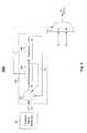
- FIG. 3Aillustrates a RF communication system 300 .
- RF communication system 300includes amplifier 305 , mixer 303 , IF/baseband processor 304 , digitally controlled oscillator (DCO) 301 , and transition controller 302 .
- Amplifier 305receives and amplifies signal RFin (e.g., from an antenna).
- Mixer 303demodulates RFin by using an oscillating signal from digitally controlled oscillator 301 .
- the demodulated signal from mixer 303is received and processed by IF/baseband processor 304 .
- Transition controller 302generates a digital signal to configure digitally controlled oscillator 301 .
- the digitally controlled oscillator 301may be configured to generate signals at different frequencies and may be configured to transition from a signal having one frequency to a signal having another frequency.
- FIG. 3Billustrates an example timing diagram 310 associated with the communication system 300 of FIG. 3A .
- Timing diagram 300includes waveform f 1 showing the activation/deactivation of a first frequency, and waveform f 2 showing the activation/deactivation of a second frequency.
- DCO 301 of FIG. 3Amay be configured to generate the oscillating signal at a first frequency.
- DCO 301may be configured to generate the oscillating signal at a second frequency.
- the first frequencyis deactivated and the second frequency is activated for time intervals t 1 , t 2 , t 3 , . . . , t N ⁇ 2 , t N ⁇ 1 , t N .
- the time intervalssuccessively increase from the beginning of transition period 311 to the end of the transition period 311 .
- the transition controllermay deactivate the first frequency (i.e., the frequency of the signal before the transition) and activate the second frequency (i.e., the frequency of the signal after the transition).
- the time interval when the first frequency is deactivated and the second frequency is activatedis small. Accordingly, the average frequency is approximately the first frequency.
- the time intervalsincrease. Accordingly, toward the end of the transition period 311 , the time interval when the first frequency is deactivated and the second frequency is activated is large. Accordingly, the average frequency is approximately the second frequency.
- the intervalsmay increase according to a variety of techniques. In one embodiment, the intervals may be increased based on a transition signal such as a linear ramp, for example. As described below, different transition signals may be used.
- the time period from the beginning one time interval to the beginning of the next time intervalmay be constant across the entire transition period, as in some pulse code modulated systems (e.g., t int1 may be the same as time period t int(N ⁇ 1) ). Therefore, the time intervals (e.g. t 1 , t 2 , etc. . . . ) may correspond to transition signal which has been pulse width modulated as described in more detail below.
- FIG. 3Cillustrates an example transition signal waveform 320 and a corresponding audio signal waveform 330 associated with the communication system of FIG. 3A .
- transition signal waveform 320is a linear ramp.
- Level 321may correspond to a first frequency and level 323 may correspond to a second frequency.
- transition signal waveform 320increases from level 321 to level 323 .
- Audio signal waveform 330indicates the effect of a change in frequency on an audio signal envelope 333 after FM demodulation. The deviation of the signal illustrated by 332 is significantly reduced by using the frequency transition techniques described herein as compared with a step frequency change. In comparison with prior art techniques illustrated at 204 and 205 in FIG.
- the audio signal changeis smoother and not as abrupt, which reduces audible noise resulting from the transition.
- the above transition signalillustrates an increasing transitional waveform, it is to be understood that other embodiments of the present invention may use a transition scheme using successively decreasing time intervals and decreasing transition signals.
- the examples provided in this specification for increasing time intervals and increasing transitions signalsare, therefore, only exemplary.
- Portion 331indicates approximately where audio signal waveform 330 is perturbed by the transition signal waveform 320 , and audio signal waveform 330 moves an additional amount 332 .
- the amount of perturbation of the audio signal waveform 330may be further reduced by altering the transition signal waveform 320 as indicated by alternative transition signal waveform 324 (shown by dashed line).
- Alternative transition signal waveform 324may be associated with a higher order equation such as arctangent, for example.
- the time intervals of FIG. 3Bmay be increased successively based on the linear ramp, arctangent, or other monotonically increasing signal used for the transition signal waveform 320 .
- FIG. 4illustrates an example electronic circuit 400 for generating an oscillating signal.
- Electronic circuit 400includes transition signal generator 401 , modulator 402 , control signal generator 403 , and DCO 404 .
- Control signal generator 403may generate control signals, such as digital control signals, to configure DCO 404 to generate an oscillating signal at a first frequency.
- control signal generator 403may generate control signals to configure DCO 404 to generate an oscillating signal at a second frequency.
- the control signal generator 403may receive inputs from the transition signal generator 401 and modulator 402 to configure DCO 404 to transition from the first frequency to the second frequency.
- Transition signal generator 401generates transition signals.
- the transition signalmay be a linear ramp, an arctangent, or a combination of mathematical equations that produce a smooth transition from a first level to a second level.
- the transition signal generator 401may generate a digital signal corresponding to a continuous transitional waveform.
- the transition signalmay be a digital signal that successively increases from a first initial value to a second final value with a plurality of intermediate values.
- the first valuemay correspond to a first frequency and the second value may correspond to a second frequency.
- the transition signal generator 401is a counter, for example.
- Modulator 402modulates the transition signal provided by transition signal generator 401 .
- Modulator 402may be a pulse width modulator (PWM) such as a sigma-delta converter, for example.
- PWMpulse width modulator
- Modulator 402may convert the transition signal into a bit stream to configure DCO 404 to activate and deactivate the first and second frequencies.
- the duration of the pulse widthsmay correspond to time intervals which activate/deactivate the first and second frequencies.
- Control signal generator 403receives the modulated signal from modulator 402 and provides control signals to configure DCO 404 to transition from one frequency to another frequency. Control signal generator 403 may provide a first control word to configure DCO 404 to a first frequency and a second control word to configure DCO 404 to a second frequency. The modulated transition signal may be used to select between the first control word and the second control word during a transition period. The modulated transition signal may provide a smooth transition between the first frequency and the second frequency.
- FIG. 5illustrates an example electronic circuit 500 for generating an oscillating signal.
- Circuit 500includes transition signal generator 501 , modulator 502 , and multiplexer 503 .
- Transition signal generator 501produces 16 bit words to modulator 502 .
- Modulator 502is a sigma-delta converter in this embodiment and produces a bit stream from accumulator 502 that successively switches between a first control word and a second control word X n+1 .
- Transition signal generator 501provides a digital signal. The duration of the transition period may be programmed such that the rate of the transition may be controlled. Modulator 502 modulates the digital signal from transition signal generator 501 . Modulator 501 may be a first or higher order sigma-delta converter. A summation node 504 receives the 16 bit transition signal, subtracts the 16 bit output of quantizer 506 , and adds the result of accumulator 505 . This produces a 32 bit error signal for the input of the accumulator 505 . Accumulator 505 functions as a digital integrator to a 32 bit error signal from summation node 504 . Accumulator 505 provides an integration of the error signal to quantizer 506 . The accumulator 505 provides a sign bit output to multiplexer 503 .
- Modulator 502converts the transition signal from transition signal generator 501 into a bit stream.
- the sign bit of accumulator 505is a sigma-delta modulated bit stream of the transition signal.
- Multiplexer 503may use this bit stream to select between control words associated with the change of frequency.
- Control word X nmay correspond to a signal from DCO having a frequency f n and control word X n+1 may correspond to a signal from DCO having frequency f n+1 .
- the modulated signal from modulator 502provides a pulse width modulated signal corresponding to a smooth transition between frequency f n and frequency f n+1 .
- FIG. 6illustrates an example electronic circuit 600 for generating an oscillating signal.
- Circuit 600includes control circuit 601 , transition signal generator 602 , digital word generator 603 , multiplexer 604 , and DCO 605 .
- Multiplexer 604may be similar to multiplexer 503 of FIG. 5 .
- Multiplexer 604receives digital words from digital word generator 603 . These words may be n-bit, which corresponds to the output of multiplexer 604 and the DCO 605 circuitry used.
- DCO 605may have “n” switches which are used to configure the desired DCO frequency setting.
- transition signal generator 602generates a bit stream based on transition data 606 .
- the transition data 606may be predetermined to provide pulse width modulated data corresponding to a minimum frequency change.
- the transition datamay include pulse width modulated data corresponding to an increasing (e.g., A to B) transitional waveform and a pulse width modulated data corresponding to a decreasing (B to A) transitional waveform (as described above).
- the bit streamis stored in memory and provided to the multiplexer 604 when needed for a transition.
- Control circuit 601may determine the succession of digital words provided by digital word generator 603 .
- digital word generator 603may also be a memory for storing digital words to be coupled to DCO 605 through multiplexer 604 as described above to transition between frequencies.
- Control circuit 601may also determine the transition data 606 which may be used to transition between the digital word provided at input A of multiplexer 604 and the digital word provided at input B of multiplexer 604 .
- the transition signal generator 602uses transition data 606 to provide a bit stream to multiplexer 604 .
- Multiplexer 604switches between digital words A and B to provide successive digital words to DCO 605 based on the bit stream provided by transition signal generator 602 .
- a selection between digital word X n corresponding to frequency f n and digital word X n+1 corresponding to the next successive frequency f n+1may be responsive to the bit stream.
- Configuring DCO 605 to transitionmay include transition signal generator 602 generating the bit stream to provide the time intervals corresponding to the activation/deactivation of frequencies f n+1 and f n (as discussed above in regard to FIG. 3B ).
Landscapes
- Inductance-Capacitance Distribution Constants And Capacitance-Resistance Oscillators (AREA)
- Transmitters (AREA)
Abstract
Description
Claims (20)
Priority Applications (2)
| Application Number | Priority Date | Filing Date | Title |
|---|---|---|---|
| US12/487,425US8600324B1 (en) | 2008-06-27 | 2009-06-18 | Circuit and method for adjusting a digitally controlled oscillator |
| US14/089,515US8923788B1 (en) | 2008-06-27 | 2013-11-25 | Circuit and method for adjusting a digitally controlled oscillator |
Applications Claiming Priority (2)
| Application Number | Priority Date | Filing Date | Title |
|---|---|---|---|
| US7646108P | 2008-06-27 | 2008-06-27 | |
| US12/487,425US8600324B1 (en) | 2008-06-27 | 2009-06-18 | Circuit and method for adjusting a digitally controlled oscillator |
Related Child Applications (1)
| Application Number | Title | Priority Date | Filing Date |
|---|---|---|---|
| US14/089,515ContinuationUS8923788B1 (en) | 2008-06-27 | 2013-11-25 | Circuit and method for adjusting a digitally controlled oscillator |
Publications (1)
| Publication Number | Publication Date |
|---|---|
| US8600324B1true US8600324B1 (en) | 2013-12-03 |
Family
ID=49640818
Family Applications (2)
| Application Number | Title | Priority Date | Filing Date |
|---|---|---|---|
| US12/487,425Active2031-07-20US8600324B1 (en) | 2008-06-27 | 2009-06-18 | Circuit and method for adjusting a digitally controlled oscillator |
| US14/089,515ActiveUS8923788B1 (en) | 2008-06-27 | 2013-11-25 | Circuit and method for adjusting a digitally controlled oscillator |
Family Applications After (1)
| Application Number | Title | Priority Date | Filing Date |
|---|---|---|---|
| US14/089,515ActiveUS8923788B1 (en) | 2008-06-27 | 2013-11-25 | Circuit and method for adjusting a digitally controlled oscillator |
Country Status (1)
| Country | Link |
|---|---|
| US (2) | US8600324B1 (en) |
Cited By (16)
| Publication number | Priority date | Publication date | Assignee | Title |
|---|---|---|---|---|
| US8649734B1 (en) | 2007-08-13 | 2014-02-11 | Marvell International Ltd. | Bluetooth scan modes |
| US8655279B2 (en) | 2008-06-16 | 2014-02-18 | Marvell World Trade Ltd. | Short-range wireless communication |
| US8923788B1 (en) | 2008-06-27 | 2014-12-30 | Marvell International Ltd. | Circuit and method for adjusting a digitally controlled oscillator |
| US8983557B1 (en) | 2011-06-30 | 2015-03-17 | Marvell International Ltd. | Reducing power consumption of a multi-antenna transceiver |
| US9055460B1 (en) | 2008-08-11 | 2015-06-09 | Marvell International Ltd. | Location-based detection of interference in cellular communications systems |
| US9066369B1 (en) | 2009-09-16 | 2015-06-23 | Marvell International Ltd. | Coexisting radio communication |
| US9078108B1 (en) | 2011-05-26 | 2015-07-07 | Marvell International Ltd. | Method and apparatus for off-channel invitation |
| US9125216B1 (en) | 2011-09-28 | 2015-09-01 | Marvell International Ltd. | Method and apparatus for avoiding interference among multiple radios |
| US9131520B1 (en) | 2009-04-06 | 2015-09-08 | Marvell International Ltd. | Packet exchange arbitration for coexisting radios |
| US9148200B1 (en) | 2007-12-11 | 2015-09-29 | Marvell International Ltd. | Determining power over ethernet impairment |
| US9215708B2 (en) | 2012-02-07 | 2015-12-15 | Marvell World Trade Ltd. | Method and apparatus for multi-network communication |
| US9294997B1 (en) | 2010-05-11 | 2016-03-22 | Marvell International Ltd. | Wakeup beacons for mesh networks |
| US9332488B2 (en) | 2010-10-20 | 2016-05-03 | Marvell World Trade Ltd. | Pre-association discovery |
| US9401737B1 (en) | 2007-09-21 | 2016-07-26 | Marvell International Ltd. | Circuits and methods for generating oscillating signals |
| US9450649B2 (en) | 2012-07-02 | 2016-09-20 | Marvell World Trade Ltd. | Shaping near-field transmission signals |
| US9655041B1 (en) | 2008-12-31 | 2017-05-16 | Marvell International Ltd. | Discovery-phase power conservation |
Citations (50)
| Publication number | Priority date | Publication date | Assignee | Title |
|---|---|---|---|---|
| US5347234A (en)* | 1993-03-26 | 1994-09-13 | International Business Machines Corp. | Digital voltage controlled oscillator |
| US5634207A (en) | 1995-02-13 | 1997-05-27 | Kabushiki Kaisha Toshiba | Frequency converter capable of reducing noise components in local oscillation signals |
| US5847616A (en) | 1996-12-12 | 1998-12-08 | Tritech Microelectronics International, Ltd. | Embedded voltage controlled oscillator with minimum sensitivity to process and supply |
| US5995819A (en) | 1995-11-22 | 1999-11-30 | Kabushiki Kaisha Toshiba | Frequency converter and radio receiver using same |
| US6167245A (en) | 1998-05-29 | 2000-12-26 | Silicon Laboratories, Inc. | Method and apparatus for operating a PLL with a phase detector/sample hold circuit for synthesizing high-frequency signals for wireless communications |
| US6285262B1 (en) | 1998-06-30 | 2001-09-04 | Kabushiki Kaisha Toshiba | Frequency divider, a phase lock oscillator and a flip-flop circuit using the frequency divider |
| US6438364B1 (en) | 2000-06-06 | 2002-08-20 | Philips Electronics North America Corporation | Radio frequency device with fast charging of an input capacitance |
| US6452458B1 (en) | 1999-04-30 | 2002-09-17 | Nec Corporation | Voltage-controlled oscillator |
| US6509777B2 (en) | 2001-01-23 | 2003-01-21 | Resonext Communications, Inc. | Method and apparatus for reducing DC offset |
| US6535037B2 (en) | 2000-02-04 | 2003-03-18 | James Maligeorgos | Injection locked frequency multiplier |
| US20030148750A1 (en) | 2002-02-07 | 2003-08-07 | Yan Kelvin Kai Tuan | DC offset correction using dummy amplifier |
| US6650195B1 (en) | 2001-07-30 | 2003-11-18 | Xilinx, Inc. | Oscillator with differential tunable tank circuit |
| US20040198297A1 (en) | 2003-04-01 | 2004-10-07 | Oh Seung Min | Quadrature signal generator with feedback type frequency doubler |
| US20050064840A1 (en) | 2003-05-30 | 2005-03-24 | The Regents Of The University Of California | Wideband distributed mixers |
| US20050090218A1 (en) | 2003-10-24 | 2005-04-28 | Matsushita Electric Industrial Co., Ltd. | Oscillation device and mobile communication apparatus |
| US20060049880A1 (en) | 2004-09-03 | 2006-03-09 | Hans-Martin Rein | Voltage controlled oscillator (vco) with output buffer |
| US20060114044A1 (en) | 2004-11-30 | 2006-06-01 | Svilen Mintchev | Differential delay cell having controllable amplitude output |
| US20060128347A1 (en)* | 2003-12-02 | 2006-06-15 | Pramote Piriyapoksombut | Radio integrated circuit with integrated power amplifier |
| US20060223474A1 (en) | 2005-03-29 | 2006-10-05 | Yasunobu Yoshizaki | Semiconductor integrated circuit |
| US7139540B2 (en) | 1999-10-21 | 2006-11-21 | Broadcom Corporation | Adaptive radio transceiver with calibration |
| US20070077908A1 (en) | 1998-11-12 | 2007-04-05 | Broadcom Corporation | Fully integrated tuner architecture |
| US7212798B1 (en) | 2003-07-17 | 2007-05-01 | Cisco Technology, Inc. | Adaptive AGC in a wireless network receiver |
| US20070142080A1 (en) | 2002-12-20 | 2007-06-21 | Renesas Technology Corp | Direct-conversion transmitter circuit and transceiver system |
| US20070173286A1 (en) | 2005-04-04 | 2007-07-26 | Broadcom Corporation, A California Corporation | Distribution of shared local oscillation to multiple RF intefaces of a wireless device |
| US20070200622A1 (en) | 2006-01-05 | 2007-08-30 | Stmicroelectronics S.R.L. | Modulator apparatus operating at low supply voltage, and corresponding method of modulation |
| US20070202814A1 (en) | 2003-10-01 | 2007-08-30 | Ikuya Ono | Wireless communication semiconductor integrated circuit device and wireless communication system |
| US7286009B2 (en)* | 2005-12-30 | 2007-10-23 | D2Audio Corporation | Digital PWM amplifier with simulation-based feedback |
| US20070264959A1 (en) | 2006-05-11 | 2007-11-15 | M/A-Com, Inc. | Quadrature sub-harmonic frequency down-converter |
| US7298183B2 (en) | 2005-06-01 | 2007-11-20 | Wilinx Corp. | High frequency divider circuits and methods |
| US7310023B2 (en) | 2005-07-05 | 2007-12-18 | Samsung Electronics Co., Ltd. | Frequency synthesizer |
| US7319849B2 (en) | 2005-08-25 | 2008-01-15 | Microtune (Texas), L.P. | Radio-frequency tuner with differential converter |
| US20080045162A1 (en) | 1999-10-21 | 2008-02-21 | Broadcom Corporation | Adaptive radio transceiver |
| US20080111639A1 (en)* | 2006-10-27 | 2008-05-15 | Interuniversitair Microelektronica Centrum (Imec) | Device and method for generating a signal with predefined transcient at start-up |
| US7395040B2 (en) | 2005-03-29 | 2008-07-01 | Broadcom Corporation | Multiple band multiple input multiple output transceiver integrated circuit |
| US20080261552A1 (en) | 2007-04-19 | 2008-10-23 | Mediatek Inc. | Low voltage iq dual mixer |
| US20080272818A1 (en) | 2007-05-02 | 2008-11-06 | Tli Inc. | Voltage-controlled oscillator generating output signal finely tunable in wide frequency range and variable delay circuits included therein |
| US7616935B2 (en)* | 2001-11-09 | 2009-11-10 | Qualcomm Incorporated | Method and apparatus for matching receiver carrier frequency |
| US20090280762A1 (en) | 2008-05-09 | 2009-11-12 | Samsung Electro-Mechanics Co., Ltd. | High-order harmonic rejection mixer using current steering technique |
| US20090312056A1 (en)* | 2008-06-17 | 2009-12-17 | Telefonaktiebolaget Lm Ericsson (Publ) | Relative Frequency Error Compensation for Multi-Carrier Receivers |
| US7656205B2 (en) | 2008-01-21 | 2010-02-02 | National Taiwan University | Dual-injection locked frequency dividing circuit |
| US7672645B2 (en) | 2006-06-15 | 2010-03-02 | Bitwave Semiconductor, Inc. | Programmable transmitter architecture for non-constant and constant envelope modulation |
| US20100052796A1 (en)* | 2008-08-29 | 2010-03-04 | Infineon Technologies Ag | Device Having Digitally Controlled Oscillator |
| US7689190B2 (en)* | 2004-09-30 | 2010-03-30 | St-Ericsson Sa | Controlling the frequency of an oscillator |
| US20100080319A1 (en)* | 2008-09-30 | 2010-04-01 | Thomas Blocher | High Bandwidth Modulation and Transmission |
| US20100283654A1 (en)* | 2007-06-22 | 2010-11-11 | Texas Instruments Incorporated | Digital phase locked loop with dithering |
| US8077652B2 (en)* | 2006-10-03 | 2011-12-13 | Viasat, Inc. | MF-TDMA frequency hopping |
| US8081038B2 (en) | 2008-12-22 | 2011-12-20 | Electronics And Telecommunications Research Institute | Ring oscillator having wide frequency range |
| US20120025921A1 (en) | 2010-07-31 | 2012-02-02 | Quintic Holdings | Low Noise VCO Circuit Having Low Noise Bias |
| US8139670B1 (en) | 2007-09-21 | 2012-03-20 | Marvell International Ltd. | Modular MIMO transceiver architecture |
| US20130057344A1 (en) | 2008-04-18 | 2013-03-07 | Stmicroelectronics (Grenoble) Sas | Differential rf amplifier |
Family Cites Families (248)
| Publication number | Priority date | Publication date | Assignee | Title |
|---|---|---|---|---|
| US4337463A (en) | 1980-08-22 | 1982-06-29 | Control Data Corporation | Time synchronization master station and remote station system |
| US4805215A (en) | 1986-10-01 | 1989-02-14 | Racal Data Communications Inc. | Adaptive echo canceller with sparse dynamically positioned taps |
| US5673291A (en) | 1994-09-14 | 1997-09-30 | Ericsson Inc. | Simultaneous demodulation and decoding of a digitally modulated radio signal using known symbols |
| US5708656A (en) | 1996-09-11 | 1998-01-13 | Nokia Mobile Phones Limited | Method and apparatus for packet data transmission |
| US6594238B1 (en) | 1998-06-19 | 2003-07-15 | Telefonaktiebolaget Lm Ericsson (Publ) | Method and apparatus for dynamically adapting a connection state in a mobile communications system |
| US6205334B1 (en) | 1998-11-24 | 2001-03-20 | Ericsson Inc. | Accelerated scanning of cellular channels by cellular radiotelephones |
| US6320919B1 (en) | 1998-11-30 | 2001-11-20 | Ericsson Inc. | Adaptive channel characterization using decoded symbols |
| US6366622B1 (en) | 1998-12-18 | 2002-04-02 | Silicon Wave, Inc. | Apparatus and method for wireless communications |
| US7612470B2 (en) | 1999-01-12 | 2009-11-03 | Microsemi Corp.—Analog Mixed Signal Group Ltd. | System for providing power over Ethernet through a patch panel |
| US6754189B1 (en) | 1999-04-08 | 2004-06-22 | Lucent Technologies Inc. | Method of queue length based burst management in wireless communication systems |
| US6640308B1 (en) | 1999-04-16 | 2003-10-28 | Invensys Systems, Inc. | System and method of powering and communicating field ethernet device for an instrumentation and control using a single pair of powered ethernet wire |
| EP1734461A2 (en) | 1999-07-12 | 2006-12-20 | Matsushita Electric Industrial Co., Ltd. | Mobile body discrimination apparatus for rapidly acquiring respective data sets transmitted through modulation of reflected radio waves by transponders which are within a communication region of an interrogator apparatus |
| JP3127918B1 (en) | 1999-07-14 | 2001-01-29 | 住友電気工業株式会社 | Road-to-vehicle communication system, roadside communication station and on-vehicle mobile station |
| US6571181B1 (en) | 1999-08-11 | 2003-05-27 | Broadcom Corporation | System and method for detecting a device requiring power |
| JP3349477B2 (en) | 1999-09-08 | 2002-11-25 | 三洋電機株式会社 | Mobile communication device, mobile communication system, and communication channel assignment request method |
| US6675328B1 (en) | 1999-10-08 | 2004-01-06 | Vigilant Networks, Llc | System and method to determine data throughput in a communication network |
| US6519461B1 (en) | 1999-10-29 | 2003-02-11 | Telefonaktiebolaget Lm Ericsson (Publ) | Channel-type switching from a common channel to a dedicated channel based on common channel load |
| US6374117B1 (en) | 1999-12-22 | 2002-04-16 | Telefonaktiebolaget Lm Ericsson (Publ) | Queue based power control scheduling |
| EP1133118A3 (en) | 2000-03-10 | 2002-02-06 | Alcatel | IP/Data traffic allocating method to maintain QoS |
| JP2001285129A (en) | 2000-03-29 | 2001-10-12 | Nec Corp | Circuit and method for cdma demodulation |
| GB0008488D0 (en) | 2000-04-07 | 2000-05-24 | Koninkl Philips Electronics Nv | Radio communication system and method of operating the system |
| JP3673149B2 (en) | 2000-07-11 | 2005-07-20 | クラリオン株式会社 | High speed roaming method for wireless LAN |
| US6738358B2 (en) | 2000-09-09 | 2004-05-18 | Intel Corporation | Network echo canceller for integrated telecommunications processing |
| US6950645B1 (en) | 2000-09-28 | 2005-09-27 | Palmsource, Inc. | Power-conserving intuitive device discovery technique in a bluetooth environment |
| KR100626675B1 (en) | 2000-12-21 | 2006-09-22 | 삼성전자주식회사 | Wireless communication device and control method |
| US7043242B2 (en) | 2001-01-31 | 2006-05-09 | Nokia Corporation | Measurement method and device for activating interfrequency handover in a wireless telecommunication network |
| US6741862B2 (en) | 2001-02-07 | 2004-05-25 | Airvana, Inc. | Enhanced reverse-link rate control in wireless communication |
| US6947857B2 (en) | 2001-03-16 | 2005-09-20 | Mindspeed Technologies, Inc. | Optical sequence time domain reflectometry during data transmission |
| US7151769B2 (en) | 2001-03-22 | 2006-12-19 | Meshnetworks, Inc. | Prioritized-routing for an ad-hoc, peer-to-peer, mobile radio access system based on battery-power levels and type of service |
| US20020172186A1 (en) | 2001-04-09 | 2002-11-21 | Peter Larsson | Instantaneous joint transmit power control and link adaptation for RTS/CTS based channel access |
| US6978151B2 (en) | 2001-05-10 | 2005-12-20 | Koninklijke Philips Electronics N.V. | Updating path loss estimation for power control and link adaptation in IEEE 802.11h WLAN |
| US7206840B2 (en) | 2001-05-11 | 2007-04-17 | Koninklike Philips Electronics N.V. | Dynamic frequency selection scheme for IEEE 802.11 WLANs |
| US7529548B2 (en) | 2001-06-28 | 2009-05-05 | Intel Corporation | Method and system for adapting a wireless link to achieve a desired channel quality |
| CN100380825C (en) | 2001-08-15 | 2008-04-09 | 高通股份有限公司 | Dual mode bluetooth/wireless device with power conservation features |
| CN1156179C (en) | 2001-09-03 | 2004-06-30 | 信息产业部电信传输研究所 | A method and device for dynamically adjusting channel estimation average interval |
| US7280517B2 (en) | 2001-11-02 | 2007-10-09 | At&T Corp. | Wireless LANs and neighborhood capture |
| US7936714B1 (en) | 2002-03-11 | 2011-05-03 | Netgear, Inc. | Spectrum allocation system and method for multi-band wireless RF data communications |
| US7269151B2 (en) | 2002-04-22 | 2007-09-11 | Cognio, Inc. | System and method for spectrum management of a shared frequency band |
| US7005861B1 (en) | 2002-06-07 | 2006-02-28 | Marvell International Ltd. | Cable tester |
| US7173431B1 (en) | 2002-06-07 | 2007-02-06 | Marvell International Ltd. | Cable tester |
| US7194283B2 (en) | 2002-08-14 | 2007-03-20 | Intel Corporation | Method and apparatus for communication using multiple communication protocols |
| GB0220660D0 (en) | 2002-09-05 | 2002-10-16 | Nokia Corp | Signal propogation delay routing |
| US20040063403A1 (en) | 2002-09-30 | 2004-04-01 | Durrant Randolph L. | Methods for identification of IEEE 802.11b radio signals |
| US7013158B1 (en) | 2002-11-25 | 2006-03-14 | Sprint Spectrum L.P. | Method and system for brokering frequencies to facilitate peer-to-peer communication |
| KR100457537B1 (en) | 2002-12-02 | 2004-11-17 | 삼성전자주식회사 | Apparatus and method for reducing power consumption in a ad-hoc network |
| US7328037B2 (en) | 2002-12-09 | 2008-02-05 | Intel Corporation | Method and apparatus to control transmitter |
| US7747244B2 (en) | 2003-01-23 | 2010-06-29 | Research In Motion Limited | Methods and apparatus for re-establishing communication for a wireless communication device after a communication loss in a wireless communication network |
| US20040192222A1 (en) | 2003-03-26 | 2004-09-30 | Nokia Corporation | System and method for semi-simultaneously coupling an antenna to transceivers |
| US7039410B2 (en) | 2003-04-22 | 2006-05-02 | Lucent Technologies Inc. | Method of handoff at the border between CDMA underlay and overlay systems |
| RU2292123C2 (en) | 2003-05-06 | 2007-01-20 | Самсунг Электроникс Ко., Лтд | Device and method for detection of route in temporarily created mobile communication network |
| US7595768B2 (en) | 2003-06-27 | 2009-09-29 | Intel Corporation | Switching schemes for multiple antennas |
| CN1567869B (en) | 2003-06-30 | 2010-05-05 | 叶启祥 | Interference control method capable of avoiding interference damage and increasing space reuse rate |
| US7715434B2 (en) | 2003-07-30 | 2010-05-11 | Michael Andrew Fischer | Managing an access point in the presence of separate protocols that share the same communications channel |
| US20050025104A1 (en) | 2003-07-30 | 2005-02-03 | Fischer Michael Andrew | Managing coexistence of separate protocols sharing the same communications channel |
| US7257095B2 (en) | 2003-07-30 | 2007-08-14 | Texas Instruments Incorporated | Power saving via physical layer address filtering in WLANs |
| US20050038876A1 (en) | 2003-08-15 | 2005-02-17 | Aloke Chaudhuri | System and method for instant match based on location, presence, personalization and communication |
| KR100970725B1 (en) | 2003-09-17 | 2010-07-16 | 삼성전자주식회사 | Frequency subband allocation method and management device |
| JP4185853B2 (en) | 2003-11-28 | 2008-11-26 | 株式会社日立コミュニケーションテクノロジー | Wireless system, server, and mobile station |
| US8483105B2 (en) | 2003-10-15 | 2013-07-09 | Qualcomm Incorporated | High speed media access control |
| AU2004290463A1 (en) | 2003-11-19 | 2005-06-02 | Acrux Dds Pty Ltd | Method and composition for treatment of cutaneous lesions |
| US8024487B2 (en) | 2003-12-01 | 2011-09-20 | Microsoft Corporation | Smart scan for wireless devices |
| KR100669238B1 (en) | 2003-12-19 | 2007-01-15 | 한국전자통신연구원 | How to provide routing protocol of sensor network |
| US7342895B2 (en) | 2004-01-30 | 2008-03-11 | Mark Serpa | Method and system for peer-to-peer wireless communication over unlicensed communication spectrum |
| US8744516B2 (en) | 2004-02-05 | 2014-06-03 | Sri International | Generic client for communication devices |
| JP4349142B2 (en) | 2004-02-09 | 2009-10-21 | ソニー株式会社 | Wireless communication apparatus, wireless communication method, and computer program |
| US7233773B2 (en) | 2004-02-13 | 2007-06-19 | Broadcom Corporation | Configuring a MIMO communication |
| US7377441B2 (en) | 2004-03-05 | 2008-05-27 | Microvision, Inc. | Electronic device with auxiliary interfaces |
| US7734253B2 (en) | 2004-03-29 | 2010-06-08 | Intel Corporation | Apparatus and methods for coexistence of collocated wireless local area network and bluetooth® based on dynamic fragmentation of WLAN packets |
| US7660287B2 (en) | 2004-04-05 | 2010-02-09 | Telefonaktiebolaget Lm Ericsson (Publ) | Method, communication device and system for address resolution mapping in a wireless multihop ad hoc network |
| JP4475639B2 (en) | 2004-04-14 | 2010-06-09 | キヤノン株式会社 | Wireless terminal apparatus, control method thereof and communication control method |
| KR100603561B1 (en) | 2004-04-16 | 2006-07-24 | 삼성전자주식회사 | Wireless LAN system based on transmission power control and transmission power control method thereof |
| CZ2006687A3 (en) | 2004-05-05 | 2007-03-28 | Qualcomm Incorporated | Method and apparatus for adaptive delay management in a wireless communication system |
| CN1951068B (en) | 2004-05-07 | 2012-12-05 | 皇家飞利浦电子股份有限公司 | A method for media distribution reservation in radio communication network |
| US20050254423A1 (en) | 2004-05-12 | 2005-11-17 | Nokia Corporation | Rate shaper algorithm |
| ATE447267T1 (en) | 2004-06-16 | 2009-11-15 | Koninkl Philips Electronics Nv | DISTRIBUTED RESOURCE RESERVATION IN A WIRELESS AD-HOC NETWORK |
| US7627026B2 (en) | 2004-07-01 | 2009-12-01 | Broadcom Corporation | Threshold setting using piecewise linear approximation for channel diagnostic systems |
| US7636388B2 (en) | 2004-07-01 | 2009-12-22 | Broadcom Corporation | Channel fault detection for channel diagnostic systems |
| US7627025B2 (en) | 2004-07-01 | 2009-12-01 | Broadcom Corporation | Echo canceller gain control for channel diagnostic systems |
| US20080095058A1 (en) | 2004-07-09 | 2008-04-24 | Koninklijke Philips Electronics, N.V. | Data Transmission in a Communication Network |
| JP2006093945A (en) | 2004-09-22 | 2006-04-06 | Nec Corp | Radio lan handover method and radio lan apparatus |
| US7903137B2 (en) | 2004-10-15 | 2011-03-08 | Lifesize Communications, Inc. | Videoconferencing echo cancellers |
| KR101075309B1 (en) | 2004-10-20 | 2011-10-19 | 톰슨 라이센싱 | Method for mobile terminal access to wireless lan based on access point services and service parameters |
| JP4678847B2 (en) | 2004-10-28 | 2011-04-27 | 信越化学工業株式会社 | Adhesive film having an adhesive layer obtained from a silicone composition |
| KR100582727B1 (en) | 2004-12-08 | 2006-05-22 | 삼성전자주식회사 | Wireless LAN transmission power control system and method |
| US20060128308A1 (en) | 2004-12-10 | 2006-06-15 | Texas Instruments Incorporated | Low power bluetooth page and inquiry scan |
| JP2006174162A (en) | 2004-12-16 | 2006-06-29 | Canon Inc | Wireless access point |
| US7626966B1 (en) | 2005-01-06 | 2009-12-01 | Idealab | Ad hoc wireless communication system |
| CN101116365A (en) | 2005-02-18 | 2008-01-30 | 富士通株式会社 | Base station and method for reducing interference in the base station |
| WO2006090254A1 (en) | 2005-02-25 | 2006-08-31 | Nokia Corporation | Method and system for voip over wlan to bluetooth headset using advanced esco scheduling |
| US7370362B2 (en) | 2005-03-03 | 2008-05-06 | Cisco Technology, Inc. | Method and apparatus for locating rogue access point switch ports in a wireless network |
| US20060199565A1 (en) | 2005-03-07 | 2006-09-07 | Wialan Technology A Florida Corporation | Enhancement to the IEEE 802.11 protocol handshake |
| US7813295B2 (en) | 2005-03-09 | 2010-10-12 | Broadcom Corporation | Co-location interference avoidance in multiple protocol communication networks |
| US20060203841A1 (en) | 2005-03-09 | 2006-09-14 | Fischer Matthew J | Coordination of multiple protocols using a shared communication medium |
| CN101138207B (en) | 2005-03-10 | 2011-08-17 | 汤姆森许可贸易公司 | Method and Access Point for Hybrid Mesh Routing |
| US7826408B1 (en) | 2005-03-14 | 2010-11-02 | Ozmo, Inc. | Apparatus and method for integrating short-range wireless personal area networks for a wireless local area network infrastructure |
| CA2600724A1 (en) | 2005-03-14 | 2006-09-21 | H-Stream Wireless, Inc. | Method and apparatus for operating a wireless pan network using an overlay protocol that enhances co-existence with a wireless lan network |
| ATE549879T1 (en) | 2005-05-02 | 2012-03-15 | Mitsubishi Electric Corp | METHOD AND APPARATUS FOR HANDLING SIGNAL MEASUREMENTS IN A WIRELESS NETWORK |
| US20060268756A1 (en) | 2005-05-03 | 2006-11-30 | Hong Kong Applied Science And Technology Research Institute Co., Ltd. | Systems and methods for efficient hand-off in wireless networks |
| US7599686B2 (en) | 2005-05-06 | 2009-10-06 | Dell Products L.P. | Systems and methods for RF spectrum management |
| US7668269B2 (en) | 2005-05-09 | 2010-02-23 | Ati Technologies, Inc. | Systems, methods, and apparatus for phase noise mitigation |
| KR101235993B1 (en) | 2005-05-12 | 2013-02-21 | 삼성전자주식회사 | Method and apparatus for scheduling in a wireless local network mesh communication system |
| KR101337126B1 (en) | 2005-05-12 | 2013-12-05 | 삼성전자주식회사 | Method and apparatus for achieving re-association of handover in a wireless local area network mesh network |
| US9031604B2 (en) | 2005-06-02 | 2015-05-12 | Broadcom Corporation | Method and apparatus for enabling simultaneous VoWLAN and Bluetooth audio in small form factor handheld devices |
| JP4455418B2 (en) | 2005-06-13 | 2010-04-21 | キヤノン株式会社 | Communication parameter setting method and communication apparatus |
| KR100975698B1 (en) | 2005-06-13 | 2010-08-12 | 삼성전자주식회사 | Relay communication system and method for cellular communication |
| JP4834352B2 (en) | 2005-06-14 | 2011-12-14 | 株式会社エヌ・ティ・ティ・ドコモ | Base station, mobile station, and power control method |
| JP2007005897A (en) | 2005-06-21 | 2007-01-11 | Toshiba Corp | Wireless communication apparatus, wireless communication method, and wireless communication system |
| US7961627B2 (en) | 2005-06-24 | 2011-06-14 | Mitsubishi Electric Research Laboratories, Inc. | Method and system for generating antenna selection signals in OFDM transceivers with fewer RF chains than antennas in MIMO wireless networks |
| US7979368B2 (en) | 2005-07-01 | 2011-07-12 | Crossbeam Systems, Inc. | Systems and methods for processing data flows |
| US20070010237A1 (en) | 2005-07-05 | 2007-01-11 | Airgo Networks, Inc. | Mac-level protection for networking extended-range and legacy devices in a wireless network |
| FI20055389A0 (en) | 2005-07-05 | 2005-07-05 | Nokia Corp | Improved detection of invalid channel access requests |
| US8169980B2 (en) | 2005-07-11 | 2012-05-01 | Qualcomm Incorporated | Methods and apparatuses for interworking |
| US7970017B2 (en) | 2005-07-13 | 2011-06-28 | At&T Intellectual Property I, L.P. | Peer-to-peer synchronization of data between devices |
| US7564826B2 (en) | 2005-07-13 | 2009-07-21 | Texas Instruments Incorporated | Apparatus for and method of synchronization and beaconing in a WLAN mesh network |
| US9184898B2 (en) | 2005-08-01 | 2015-11-10 | Google Technology Holdings LLC | Channel quality indicator for time, frequency and spatial channel in terrestrial radio access network |
| DE602005008949D1 (en) | 2005-08-04 | 2008-09-25 | St Microelectronics Srl | Method and system for dynamic spectrum allocation, and corresponding computer program product |
| US7599671B2 (en) | 2005-08-08 | 2009-10-06 | Marvell World Trade Ltd. | Radar detection apparatus and method thereof |
| US7717342B2 (en) | 2005-08-26 | 2010-05-18 | Hand Held Products, Inc. | Data collection device having dynamic access to multiple wireless networks |
| US7809960B2 (en) | 2005-10-12 | 2010-10-05 | Cicchetti Christopher J | Network tap device powered by power over ethernet |
| WO2007054930A1 (en) | 2005-11-10 | 2007-05-18 | Powerdsine, Ltd. | Enhanced classification for power over ethernet |
| EP1958369B1 (en) | 2005-12-01 | 2015-04-08 | Ruckus Wireless, Inc. | On-demand services by wireless base station virtualization |
| JP4558639B2 (en) | 2005-12-16 | 2010-10-06 | 富士通株式会社 | Wireless LAN device and communication mode switching method |
| US20090005061A1 (en) | 2005-12-30 | 2009-01-01 | Trueposition, Inc. | Location quality of service indicator |
| KR100738557B1 (en) | 2006-02-08 | 2007-07-11 | 삼성전자주식회사 | Apparatus and method for transmitting data frame in wireless LAN terminal |
| US7885398B2 (en) | 2006-03-06 | 2011-02-08 | Alcatel Lucent | Multiple criteria based load balancing |
| US7583625B2 (en) | 2006-04-06 | 2009-09-01 | Broadcom Corporation | Access point multi-level transmission power and protocol control based on the exchange of characteristics |
| US20080056201A1 (en) | 2006-03-22 | 2008-03-06 | Broadcom Corporation, A California Corporation | Interference parameter reporting from client devices to access point for use in modifying wireless operations |
| US8170546B2 (en) | 2006-03-22 | 2012-05-01 | Broadcom Corporation | Client device characterization of other client device transmissions and reporting of signal qualities to access point(s) |
| US7778226B2 (en) | 2006-03-30 | 2010-08-17 | Intel Corporation | Device, system and method of coordination among multiple transceivers |
| JP4781880B2 (en) | 2006-03-31 | 2011-09-28 | 富士通株式会社 | Relay device, relay method, relay program, and communication system |
| US7535884B2 (en) | 2006-04-18 | 2009-05-19 | Cisco Technology, Inc. | Battery-efficient generic advertising service for wireless mobile devices |
| US7711004B2 (en) | 2006-04-18 | 2010-05-04 | Cisco Technology, Inc. | Multiple broadcast channels for wireless networks |
| WO2007125175A2 (en) | 2006-05-02 | 2007-11-08 | Ant - Advanced Network Technologies Oy | Method and system for wireless real-time transmission of multichannel audio or video data |
| US7849333B2 (en) | 2006-05-08 | 2010-12-07 | Cisco Technology, Inc. | Inline power allocation for power over Ethernet applications |
| US8155649B2 (en) | 2006-05-12 | 2012-04-10 | Shared Spectrum Company | Method and system for classifying communication signals in a dynamic spectrum access system |
| US7920885B2 (en) | 2006-05-18 | 2011-04-05 | Samsung Electronics Co., Ltd. | Method and system for establishing a connection on a secondary frequency channel for wireless communication |
| US8442434B2 (en) | 2006-05-24 | 2013-05-14 | Broadcom Corporation | Method and system for auto coexistence priority selection for a SCO link |
| US8643218B2 (en) | 2006-06-02 | 2014-02-04 | Broadcom Corporation | Minimizing saturation caused by power transfer in a communication system transformer |
| US7801084B2 (en) | 2006-06-09 | 2010-09-21 | Intel Corporation | Doppler frequency determination for mobile wireless devices |
| US7864682B2 (en) | 2006-06-27 | 2011-01-04 | Samsung Electronics Co., Ltd. | Method for routing data in networks |
| US20080056227A1 (en) | 2006-08-31 | 2008-03-06 | Motorola, Inc. | Adaptive broadcast multicast systems in wireless communication networks |
| US8532023B2 (en) | 2006-09-20 | 2013-09-10 | Alcatel Lucent | Interference aware routing in multi-radio wireless mesh networks |
| US20080080446A1 (en) | 2006-09-28 | 2008-04-03 | Mediatek Inc. | Systems and methods for power management in a multiple input multiple output (mimo) wireless local area network (wlan) |
| US8270302B2 (en) | 2006-10-20 | 2012-09-18 | Stmicroelectronics, Inc. | System and method for providing an adaptive value of TTL (time to live) for broadcast/multicast messages in a mesh network using a hybrid wireless mesh protocol |
| MY164442A (en) | 2006-10-23 | 2017-12-15 | Interdigital Tech Corp | Method and apparatus for sending a channel quality indication via a shared channel |
| KR20090074257A (en) | 2006-11-08 | 2009-07-06 | 가부시키가이샤 엔티티 도코모 | Mobile communication system, base station and mobile station and communication control method |
| US8976670B2 (en) | 2006-11-16 | 2015-03-10 | Rockstar Consortium Us Lp | System and method for delivering packet data over a multiplicity of communication links |
| US8576873B2 (en) | 2006-11-30 | 2013-11-05 | Broadcom Corporation | System and method for controlling power delivered to a powered device based on channel impediments |
| US8050241B2 (en) | 2006-11-30 | 2011-11-01 | Research In Motion Limited | Determining identifiers for wireless networks |
| US7876786B2 (en) | 2006-12-01 | 2011-01-25 | Microsoft Corporation | Dynamic time-spectrum block allocation for cognitive radio networks |
| US20080139212A1 (en) | 2006-12-07 | 2008-06-12 | Motorola, Inc. | Apparatus and method for interoperation of various radio links with a piconet link in a wireless device |
| US7920883B2 (en) | 2006-12-28 | 2011-04-05 | Hewlett-Packard Development Company, L.P. | Coordination of transmissions in wireless communications devices |
| US7355416B1 (en) | 2007-01-07 | 2008-04-08 | Microsemi Corp.- Analog Mixed Signal Group Ltd. | Measurement of cable quality by power over ethernet |
| JP5014820B2 (en) | 2007-01-09 | 2012-08-29 | 株式会社エヌ・ティ・ティ・ドコモ | Mobile communication system, user apparatus and communication method |
| US20080181154A1 (en) | 2007-01-31 | 2008-07-31 | Texas Instruments Incorporated | Apparatus for and method of low power wireless local area network independent basic service set mode operation |
| US20080186860A1 (en) | 2007-02-06 | 2008-08-07 | Viasat, Inc. | Contention and polled requests for scheduling transmissions |
| US8170002B2 (en) | 2007-05-31 | 2012-05-01 | Conexant Systems, Inc. | Systems and methods for indicating buffered data at an access point with efficient beacon handling |
| US20080232287A1 (en) | 2007-03-21 | 2008-09-25 | Samsung Electronics Co., Ltd. | Method and system for power saving scheduling in wireless local area networks |
| US8406319B2 (en) | 2007-03-27 | 2013-03-26 | Motorola Mobility Llc | Channel estimator with high noise suppression and low interpolation error for OFDM systems |
| JP5106902B2 (en) | 2007-03-29 | 2012-12-26 | 京セラ株式会社 | Communication control method |
| US7679514B2 (en) | 2007-03-30 | 2010-03-16 | Broadcom Corporation | Multi-mode RFID tag architecture |
| US8428002B2 (en) | 2007-04-18 | 2013-04-23 | Broadcom Corporation | Cooperative transceiving between wireless interface devices of a host device |
| US7801099B2 (en) | 2007-05-10 | 2010-09-21 | Broadcom Corporation | Cooperative transceiving between wireless interface devices of a host device with acknowledge priority |
| US7881746B2 (en) | 2007-05-10 | 2011-02-01 | Broadcom Corporation | Shared processing between wireless interface devices of a host device |
| US7826411B2 (en) | 2007-05-10 | 2010-11-02 | Broadcom Corporation | Cooperative transceiving between wireless interface devices of a host device with shared modules |
| WO2008150122A1 (en) | 2007-06-08 | 2008-12-11 | Lg Innotek Co., Ltd | Wireless communication device |
| US7737704B2 (en) | 2007-06-12 | 2010-06-15 | Broadcom Corporation | System and method for using a PHY to locate a thermal signature in a cable plant for diagnostic, enhanced, and higher power applications |
| US20080320108A1 (en) | 2007-06-20 | 2008-12-25 | Microsoft Corporation | Management Policies For Dense Wireless Access Point Infrastructures in Wireless Local Area Networks |
| US8014329B2 (en) | 2007-07-03 | 2011-09-06 | Cisco Technology, Inc. | Path selection and power management in mesh networks |
| US8149715B1 (en) | 2007-07-17 | 2012-04-03 | Marvell International Ltd. | Mesh network operations |
| US8369782B1 (en) | 2007-08-13 | 2013-02-05 | Marvell International Ltd. | Bluetooth wideband scan mode |
| CN101373998B (en) | 2007-08-20 | 2012-07-25 | 上海贝尔阿尔卡特股份有限公司 | Low information interactive multi-base station collaboration MIMO as well as scheduling method and apparatus thereof |
| US8553561B1 (en) | 2007-08-22 | 2013-10-08 | Marvell International Ltd. | Quality of service for mesh networks |
| US8189506B2 (en) | 2007-09-12 | 2012-05-29 | Nokia Corporation | Deep sleep mode for mesh points |
| US9686049B2 (en) | 2007-09-12 | 2017-06-20 | Avago Technologies General Ip (Singapore) Pte. Ltd | Method and system for Bluetooth (BT) delayed acknowledgement (ACK) |
| US8577305B1 (en) | 2007-09-21 | 2013-11-05 | Marvell International Ltd. | Circuits and methods for generating oscillating signals |
| US8045922B2 (en) | 2007-11-23 | 2011-10-25 | Texas Instruments Incorporated | Apparatus for and method of bluetooth and wireless local area network coexistence using a single antenna in a collocated device |
| US8588705B1 (en) | 2007-12-11 | 2013-11-19 | Marvell International Ltd. | System and method of determining Power over Ethernet impairment |
| US20090168725A1 (en) | 2007-12-26 | 2009-07-02 | Qualcomm Incorporated | Communication handover management |
| US20090170497A1 (en) | 2007-12-28 | 2009-07-02 | Guowang Miao | Probabilistic interference mitigation for wireless cellular networks |
| US8126502B2 (en) | 2007-12-31 | 2012-02-28 | Intel Corporation | Channel width switching in multiple OBSS systems |
| GB2457431A (en) | 2008-01-28 | 2009-08-19 | Fujitsu Lab Of Europ Ltd | Interference mitigation method in a wireless network |
| US8072913B2 (en) | 2008-02-03 | 2011-12-06 | Broadcom Corporation | Collaborative coexistence of co-located mobile WiMAX, wireless LAN, and/or bluetooth radios |
| US8359373B2 (en) | 2008-02-06 | 2013-01-22 | Broadcom Corporation | Handheld computing unit of a computing device with an extended computing unit |
| WO2009101567A1 (en) | 2008-02-12 | 2009-08-20 | Nxp B.V. | Wireless communications arrangement, network and approach therefor to manage a shared channel among different wireless systems |
| US8345607B2 (en) | 2008-03-10 | 2013-01-01 | Marvell World Trade Ltd. | Coexistence and collocation of remote network and local network radios |
| US20090321056A1 (en) | 2008-03-11 | 2009-12-31 | Tessera, Inc. | Multi-stage electrohydrodynamic fluid accelerator apparatus |
| CN101978610B (en) | 2008-03-18 | 2014-03-12 | 马维尔国际贸易有限公司 | Bluetooth and WLAN coexistence architecture with shared LNA |
| US8694044B2 (en) | 2008-03-25 | 2014-04-08 | Telefonaktiebolaget L M Ericsson (Publ) | Dynamic power control of user equipment |
| US20090247217A1 (en) | 2008-03-27 | 2009-10-01 | Mediatek Inc. | Apparatus and method for wireless communications capable of bluetooth, wireless local area network (wlan) and wimax communications |
| US20090245133A1 (en) | 2008-03-31 | 2009-10-01 | Intel Corporation | Broadcast/multicast based network discovery |
| US7924795B2 (en) | 2008-03-31 | 2011-04-12 | Mediatek Inc. | Apparatus and method for coordinating bluetooth and wireless local area network (WLAN) and WiMAX communications |
| WO2009146132A2 (en) | 2008-04-04 | 2009-12-03 | Powerwave Cognition, Inc. | Methods and systems for a mobile, broadband, routable internet |
| US8111677B2 (en) | 2008-04-24 | 2012-02-07 | Conexant Systems, Inc. | Systems and methods of combined bluetooth and WLAN signaling |
| US20090268652A1 (en) | 2008-04-29 | 2009-10-29 | Nokia Corporation | Power management mode aware mesh beacon collision avoidance and information update mechanism |
| US8274894B2 (en) | 2008-05-07 | 2012-09-25 | Nokia Corporation | Quality of service and power aware forwarding rules for mesh points in wireless mesh networks |
| US20090285264A1 (en) | 2008-05-13 | 2009-11-19 | Carlos Aldana | Method and System for Detection of Long Pulse Bin 5 Radars in the Presence of Greenfield Packets |
| US8489028B2 (en) | 2008-05-22 | 2013-07-16 | Qualcomm Incorporated | System and method to enable resource partitioning in wireless networks |
| US8315564B2 (en) | 2008-06-16 | 2012-11-20 | Marvell World Trade Ltd. | Short-range wireless communication |
| US9241276B2 (en) | 2008-06-17 | 2016-01-19 | Alcatel Lucent | Method for adaptive formation of cell clusters for cellular wireless networks with coordinated transmission and reception |
| US8310967B1 (en) | 2008-06-19 | 2012-11-13 | Marvell International Ltd. | Infrastructure and ad-hoc node device |
| US8600324B1 (en) | 2008-06-27 | 2013-12-03 | Marvell International Ltd | Circuit and method for adjusting a digitally controlled oscillator |
| WO2010006099A1 (en) | 2008-07-11 | 2010-01-14 | Marvell World Trade, Ltd. | Access point rotation for sharing power load |
| US8577363B2 (en) | 2008-07-14 | 2013-11-05 | Nokia Corporation | Setup of device-to-device connection |
| US8078111B2 (en) | 2008-07-29 | 2011-12-13 | Qualcomm Incorporated | Methods and apparatus for using multiple frequency bands for communication |
| US8155695B2 (en) | 2008-07-29 | 2012-04-10 | Sony Ericsson Mobile Communications Ab | Apparatus and method to improve WLAN performance in a dual WLAN modality environment |
| US8472968B1 (en) | 2008-08-11 | 2013-06-25 | Marvell International Ltd. | Location-based detection of interference in cellular communications systems |
| KR101481586B1 (en) | 2008-09-04 | 2015-01-12 | 엘지전자 주식회사 | Method for communcation time allocation of multiple radio |
| US20100069112A1 (en) | 2008-09-15 | 2010-03-18 | Texas Instruments Incorporated | Scheduling transmissions in coexisting wireless networks |
| US8150328B2 (en) | 2008-09-17 | 2012-04-03 | Motorola Solutions, Inc. | Method and apparatus for distributed sensing management and control within a cognitive radio network |
| JP5163408B2 (en) | 2008-10-01 | 2013-03-13 | 富士通株式会社 | Information processing device |
| US8107391B2 (en) | 2008-11-19 | 2012-01-31 | Wi-Lan, Inc. | Systems and etiquette for home gateways using white space |
| US20100130129A1 (en) | 2008-11-25 | 2010-05-27 | Jue Chang | WLAN and bluetooth harmonization |
| EP2277286B1 (en) | 2008-12-01 | 2016-11-23 | Marvell World Trade Ltd. | Access point enhancements |
| US8203985B2 (en) | 2008-12-31 | 2012-06-19 | Intel Corporation | Power saving in peer-to-peer communication devices |
| US8189526B2 (en) | 2009-03-06 | 2012-05-29 | Samsung Electronics Co., Ltd. | Method and system for shared communication medium in wireless communication systems |
| US8254296B1 (en) | 2009-03-19 | 2012-08-28 | Marvell International Ltd. | Peer-to-peer frequency band negotiation |
| US8472427B1 (en) | 2009-04-06 | 2013-06-25 | Marvell International Ltd. | Packet exchange arbitration for coexisting radios |
| US8532041B1 (en) | 2009-04-24 | 2013-09-10 | Marvell International Ltd. | Method for transmitting information in a regulated spectrum and network configured to operate in the regulated spectrum |
| CN102576353A (en) | 2009-05-13 | 2012-07-11 | 航空网络公司 | Systems and methods for fractional routing redundancy |
| US8229041B2 (en) | 2009-05-26 | 2012-07-24 | Broadcom Corporation | Direct detection of wireless interferers in a communication device for multiple modulation types |
| US8204015B2 (en) | 2009-05-29 | 2012-06-19 | Motorola Solutions, Inc. | Method and apparatus for zone controller based dynamic spectrum allocation |
| US20120327779A1 (en) | 2009-06-12 | 2012-12-27 | Cygnus Broadband, Inc. | Systems and methods for congestion detection for use in prioritizing and scheduling packets in a communication network |
| US8594056B2 (en) | 2009-06-16 | 2013-11-26 | Qualcomm Incorporated | Method and apparatus for dynamic and dual antenna bluetooth (BT)/WLAN coexistence |
| US8768323B2 (en) | 2009-06-23 | 2014-07-01 | Intel Corporation | Service discovery in a wireless network |
| US9025583B2 (en) | 2009-07-09 | 2015-05-05 | Mediatek Inc. | System for the coexistence between a plurality of wireless communication module sharing single antenna |
| US9130605B2 (en) | 2009-07-09 | 2015-09-08 | Mediatek Inc. | Systems and methods for coexistence between plurality of wireless communications modules sharing single antenna |
| CN102024160A (en) | 2009-09-14 | 2011-04-20 | 西门子公司 | Method and apparatus satisfying frequency spectrum template in radio frequency identification system |
| US8626067B2 (en) | 2009-10-26 | 2014-01-07 | Mediatek Inc. | System and methods for enhancing coexistence efficiency for multi-radio terminals |
| US9900759B2 (en) | 2009-11-04 | 2018-02-20 | Qualcomm Incorporated | Method and apparatus for peer discovery in a wireless communication network |
| US8340034B1 (en) | 2009-11-11 | 2012-12-25 | Marvell International Ltd. | Bluetooth and wireless LAN arbitration |
| US8335937B2 (en) | 2009-12-24 | 2012-12-18 | Intel Corporation | Method and system for discoverability of power saving P2P devices |
| US8493992B2 (en) | 2010-02-04 | 2013-07-23 | Texas Instruments Incorporated | Interrelated WiFi and USB protocols and other application framework processes, circuits and systems |
| KR101810260B1 (en) | 2010-02-12 | 2017-12-18 | 인터디지탈 패튼 홀딩스, 인크 | Method and apparatus for optimizing uplink random access channel transmission |
| KR20140112091A (en) | 2010-04-02 | 2014-09-22 | 인터디지탈 패튼 홀딩스, 인크 | Group procedures for machine type comunication devices |
| US8364188B2 (en) | 2010-06-04 | 2013-01-29 | Alcatel Lucent | Method and controller for allocating whitespace spectrum |
| KR101928448B1 (en) | 2010-10-11 | 2018-12-13 | 삼성전자주식회사 | Method and appratus for avoiding inteference from in-device communication module using time division multiplexing in wireless communication system |
| KR101616491B1 (en) | 2010-10-20 | 2016-04-28 | 마벨 월드 트레이드 리미티드 | Pre-association discovery |
| FR2967802B1 (en) | 2010-11-22 | 2012-11-23 | Inside Contactless | GSM RADIO COMMUNICATION DEVICE COMPRISING A UHF LABEL READER |
| US8805303B2 (en) | 2011-02-18 | 2014-08-12 | Blackberry Limited | Method and apparatus for avoiding in-device coexistence interference with preferred frequency notification |
| US9204398B2 (en) | 2011-03-21 | 2015-12-01 | Nokia Technologies Oy | Method and apparatus for battery with secure element |
| EP2702822B1 (en) | 2011-04-29 | 2020-02-05 | Marvell World Trade Ltd. | Multi-technology coexistence for ibss networks |
| US8655278B2 (en) | 2011-06-20 | 2014-02-18 | Hewlett-Packard Development Company, L.P. | Band steering |
| US9036517B2 (en) | 2012-01-09 | 2015-05-19 | Marvell World Trade Ltd. | Methods and apparatus for establishing a tunneled direct link setup (TDLS) session between devices in a wireless network |
| WO2013119810A1 (en) | 2012-02-07 | 2013-08-15 | Marvell World Trade Ltd. | Method and apparatus for multi-network communication |
| US20130225068A1 (en) | 2012-02-24 | 2013-08-29 | Nokia Corporation | Method, apparatus, and computer program product for coexistence-aware communication mechanism for multi-radios |
| US9450649B2 (en) | 2012-07-02 | 2016-09-20 | Marvell World Trade Ltd. | Shaping near-field transmission signals |
| US8971182B2 (en) | 2012-08-07 | 2015-03-03 | Lg Electronics Inc. | Method for data traffic offloading and apparatus using the same |
- 2009
- 2009-06-18USUS12/487,425patent/US8600324B1/enactiveActive
- 2013
- 2013-11-25USUS14/089,515patent/US8923788B1/enactiveActive
Patent Citations (54)
| Publication number | Priority date | Publication date | Assignee | Title |
|---|---|---|---|---|
| US5347234A (en)* | 1993-03-26 | 1994-09-13 | International Business Machines Corp. | Digital voltage controlled oscillator |
| US5634207A (en) | 1995-02-13 | 1997-05-27 | Kabushiki Kaisha Toshiba | Frequency converter capable of reducing noise components in local oscillation signals |
| US5995819A (en) | 1995-11-22 | 1999-11-30 | Kabushiki Kaisha Toshiba | Frequency converter and radio receiver using same |
| US5847616A (en) | 1996-12-12 | 1998-12-08 | Tritech Microelectronics International, Ltd. | Embedded voltage controlled oscillator with minimum sensitivity to process and supply |
| US6741846B1 (en) | 1998-05-29 | 2004-05-25 | Silicon Laboratories Inc. | Method and apparatus for operating a PLL with a phase detector/sample hold circuit for synthesizing high-frequency signals for wireless communications |
| US6167245A (en) | 1998-05-29 | 2000-12-26 | Silicon Laboratories, Inc. | Method and apparatus for operating a PLL with a phase detector/sample hold circuit for synthesizing high-frequency signals for wireless communications |
| US6285262B1 (en) | 1998-06-30 | 2001-09-04 | Kabushiki Kaisha Toshiba | Frequency divider, a phase lock oscillator and a flip-flop circuit using the frequency divider |
| US20070077908A1 (en) | 1998-11-12 | 2007-04-05 | Broadcom Corporation | Fully integrated tuner architecture |
| US6452458B1 (en) | 1999-04-30 | 2002-09-17 | Nec Corporation | Voltage-controlled oscillator |
| US7139540B2 (en) | 1999-10-21 | 2006-11-21 | Broadcom Corporation | Adaptive radio transceiver with calibration |
| US20110053522A1 (en) | 1999-10-21 | 2011-03-03 | Broadcom Corporation | Adaptive radio transceiver |
| US20080045162A1 (en) | 1999-10-21 | 2008-02-21 | Broadcom Corporation | Adaptive radio transceiver |
| US6535037B2 (en) | 2000-02-04 | 2003-03-18 | James Maligeorgos | Injection locked frequency multiplier |
| US6438364B1 (en) | 2000-06-06 | 2002-08-20 | Philips Electronics North America Corporation | Radio frequency device with fast charging of an input capacitance |
| US6509777B2 (en) | 2001-01-23 | 2003-01-21 | Resonext Communications, Inc. | Method and apparatus for reducing DC offset |
| US6650195B1 (en) | 2001-07-30 | 2003-11-18 | Xilinx, Inc. | Oscillator with differential tunable tank circuit |
| US7616935B2 (en)* | 2001-11-09 | 2009-11-10 | Qualcomm Incorporated | Method and apparatus for matching receiver carrier frequency |
| US6816718B2 (en) | 2002-02-07 | 2004-11-09 | Rf Micro Devices, Inc. | DC offset correction using dummy amplifier |
| US20030148750A1 (en) | 2002-02-07 | 2003-08-07 | Yan Kelvin Kai Tuan | DC offset correction using dummy amplifier |
| US20070142080A1 (en) | 2002-12-20 | 2007-06-21 | Renesas Technology Corp | Direct-conversion transmitter circuit and transceiver system |
| US20040198297A1 (en) | 2003-04-01 | 2004-10-07 | Oh Seung Min | Quadrature signal generator with feedback type frequency doubler |
| US20050064840A1 (en) | 2003-05-30 | 2005-03-24 | The Regents Of The University Of California | Wideband distributed mixers |
| US7212798B1 (en) | 2003-07-17 | 2007-05-01 | Cisco Technology, Inc. | Adaptive AGC in a wireless network receiver |
| US20070202814A1 (en) | 2003-10-01 | 2007-08-30 | Ikuya Ono | Wireless communication semiconductor integrated circuit device and wireless communication system |
| US20050090218A1 (en) | 2003-10-24 | 2005-04-28 | Matsushita Electric Industrial Co., Ltd. | Oscillation device and mobile communication apparatus |
| US20060128347A1 (en)* | 2003-12-02 | 2006-06-15 | Pramote Piriyapoksombut | Radio integrated circuit with integrated power amplifier |
| US20060049880A1 (en) | 2004-09-03 | 2006-03-09 | Hans-Martin Rein | Voltage controlled oscillator (vco) with output buffer |
| US7689190B2 (en)* | 2004-09-30 | 2010-03-30 | St-Ericsson Sa | Controlling the frequency of an oscillator |
| US20060114044A1 (en) | 2004-11-30 | 2006-06-01 | Svilen Mintchev | Differential delay cell having controllable amplitude output |
| US20090143043A1 (en) | 2005-03-29 | 2009-06-04 | Yasunobu Yoshizaki | Semiconductor integrated circuit |
| US7395040B2 (en) | 2005-03-29 | 2008-07-01 | Broadcom Corporation | Multiple band multiple input multiple output transceiver integrated circuit |
| US20060223474A1 (en) | 2005-03-29 | 2006-10-05 | Yasunobu Yoshizaki | Semiconductor integrated circuit |
| US20070173286A1 (en) | 2005-04-04 | 2007-07-26 | Broadcom Corporation, A California Corporation | Distribution of shared local oscillation to multiple RF intefaces of a wireless device |
| US7298183B2 (en) | 2005-06-01 | 2007-11-20 | Wilinx Corp. | High frequency divider circuits and methods |
| US7310023B2 (en) | 2005-07-05 | 2007-12-18 | Samsung Electronics Co., Ltd. | Frequency synthesizer |
| US7319849B2 (en) | 2005-08-25 | 2008-01-15 | Microtune (Texas), L.P. | Radio-frequency tuner with differential converter |
| US7286009B2 (en)* | 2005-12-30 | 2007-10-23 | D2Audio Corporation | Digital PWM amplifier with simulation-based feedback |
| US20070200622A1 (en) | 2006-01-05 | 2007-08-30 | Stmicroelectronics S.R.L. | Modulator apparatus operating at low supply voltage, and corresponding method of modulation |
| US20070264959A1 (en) | 2006-05-11 | 2007-11-15 | M/A-Com, Inc. | Quadrature sub-harmonic frequency down-converter |
| US7672645B2 (en) | 2006-06-15 | 2010-03-02 | Bitwave Semiconductor, Inc. | Programmable transmitter architecture for non-constant and constant envelope modulation |
| US8077652B2 (en)* | 2006-10-03 | 2011-12-13 | Viasat, Inc. | MF-TDMA frequency hopping |
| US20080111639A1 (en)* | 2006-10-27 | 2008-05-15 | Interuniversitair Microelektronica Centrum (Imec) | Device and method for generating a signal with predefined transcient at start-up |
| US20080261552A1 (en) | 2007-04-19 | 2008-10-23 | Mediatek Inc. | Low voltage iq dual mixer |
| US20080272818A1 (en) | 2007-05-02 | 2008-11-06 | Tli Inc. | Voltage-controlled oscillator generating output signal finely tunable in wide frequency range and variable delay circuits included therein |
| US20100283654A1 (en)* | 2007-06-22 | 2010-11-11 | Texas Instruments Incorporated | Digital phase locked loop with dithering |
| US8139670B1 (en) | 2007-09-21 | 2012-03-20 | Marvell International Ltd. | Modular MIMO transceiver architecture |
| US7656205B2 (en) | 2008-01-21 | 2010-02-02 | National Taiwan University | Dual-injection locked frequency dividing circuit |
| US20130057344A1 (en) | 2008-04-18 | 2013-03-07 | Stmicroelectronics (Grenoble) Sas | Differential rf amplifier |
| US20090280762A1 (en) | 2008-05-09 | 2009-11-12 | Samsung Electro-Mechanics Co., Ltd. | High-order harmonic rejection mixer using current steering technique |
| US20090312056A1 (en)* | 2008-06-17 | 2009-12-17 | Telefonaktiebolaget Lm Ericsson (Publ) | Relative Frequency Error Compensation for Multi-Carrier Receivers |
| US20100052796A1 (en)* | 2008-08-29 | 2010-03-04 | Infineon Technologies Ag | Device Having Digitally Controlled Oscillator |
| US20100080319A1 (en)* | 2008-09-30 | 2010-04-01 | Thomas Blocher | High Bandwidth Modulation and Transmission |
| US8081038B2 (en) | 2008-12-22 | 2011-12-20 | Electronics And Telecommunications Research Institute | Ring oscillator having wide frequency range |
| US20120025921A1 (en) | 2010-07-31 | 2012-02-02 | Quintic Holdings | Low Noise VCO Circuit Having Low Noise Bias |
Non-Patent Citations (8)
| Title |
|---|
| "Final Office Action", U.S. Appl. No. 12/358,955, (Feb. 17, 2012), 26 pages. |
| "Final Office Action", U.S. Appl. No. 12/358,955, Mar. 18, 2013, 12 pages. |
| "Non-Final Office Action", U.S. Appl. No. 12/235,333, (Jun. 28, 2011), 16 pages. |
| "Non-Final Office Action", U.S. Appl. No. 12/358,955, (Sep. 6, 2011), 24 pages. |
| "Non-Final Office Action", U.S. Appl. No. 12/358,955, Aug. 20, 2012, 33 pages. |
| "Notice of Allowance", U.S. Appl. No. 12/235,333, (Nov. 15, 2011), 5 pages. |
| "Notice of Allowance", U.S. Appl. No. 12/358,955, Jul. 1, 2013, 8 pages. |
| Mazzanti, et al., "Analysis and Design of Injection-Locked LC Dividers Quadrature Generation", IEEE Journal of Solid-State Circuits, vol. 39, No. 9, (Sep. 2004), pp. 1425-1433. |
Cited By (18)
| Publication number | Priority date | Publication date | Assignee | Title |
|---|---|---|---|---|
| US8897706B1 (en) | 2007-08-13 | 2014-11-25 | Marvell International Ltd. | Bluetooth wideband scan mode |
| US8649734B1 (en) | 2007-08-13 | 2014-02-11 | Marvell International Ltd. | Bluetooth scan modes |
| US9401737B1 (en) | 2007-09-21 | 2016-07-26 | Marvell International Ltd. | Circuits and methods for generating oscillating signals |
| US9148200B1 (en) | 2007-12-11 | 2015-09-29 | Marvell International Ltd. | Determining power over ethernet impairment |
| US8655279B2 (en) | 2008-06-16 | 2014-02-18 | Marvell World Trade Ltd. | Short-range wireless communication |
| US8989669B2 (en) | 2008-06-16 | 2015-03-24 | Marvell World Trade Ltd. | Short-range wireless communication |
| US8923788B1 (en) | 2008-06-27 | 2014-12-30 | Marvell International Ltd. | Circuit and method for adjusting a digitally controlled oscillator |
| US9055460B1 (en) | 2008-08-11 | 2015-06-09 | Marvell International Ltd. | Location-based detection of interference in cellular communications systems |
| US9655041B1 (en) | 2008-12-31 | 2017-05-16 | Marvell International Ltd. | Discovery-phase power conservation |
| US9131520B1 (en) | 2009-04-06 | 2015-09-08 | Marvell International Ltd. | Packet exchange arbitration for coexisting radios |
| US9066369B1 (en) | 2009-09-16 | 2015-06-23 | Marvell International Ltd. | Coexisting radio communication |
| US9294997B1 (en) | 2010-05-11 | 2016-03-22 | Marvell International Ltd. | Wakeup beacons for mesh networks |
| US9332488B2 (en) | 2010-10-20 | 2016-05-03 | Marvell World Trade Ltd. | Pre-association discovery |
| US9078108B1 (en) | 2011-05-26 | 2015-07-07 | Marvell International Ltd. | Method and apparatus for off-channel invitation |
| US8983557B1 (en) | 2011-06-30 | 2015-03-17 | Marvell International Ltd. | Reducing power consumption of a multi-antenna transceiver |
| US9125216B1 (en) | 2011-09-28 | 2015-09-01 | Marvell International Ltd. | Method and apparatus for avoiding interference among multiple radios |
| US9215708B2 (en) | 2012-02-07 | 2015-12-15 | Marvell World Trade Ltd. | Method and apparatus for multi-network communication |
| US9450649B2 (en) | 2012-07-02 | 2016-09-20 | Marvell World Trade Ltd. | Shaping near-field transmission signals |
Also Published As
| Publication number | Publication date |
|---|---|
| US8923788B1 (en) | 2014-12-30 |
Similar Documents
| Publication | Publication Date | Title |
|---|---|---|
| US8600324B1 (en) | Circuit and method for adjusting a digitally controlled oscillator | |
| US7551688B2 (en) | Waveforms for envelope tracking transmitter | |
| JP4235454B2 (en) | AGC method of highly integrated communication receiver | |
| EP1880475B1 (en) | Amplitude calibration element for an enhanced data rates for gsm evolution (edge) polar loop transmitter | |
| US8324969B2 (en) | Delta-sigma modulator approach to increased amplifier gain resolution | |
| US20050062526A1 (en) | High-efficiency amplifier, converter and methods | |
| US20080309536A1 (en) | Analog-to-Digital Converter of the Sigma Delta Type | |
| US20020015458A1 (en) | AGC circuit | |
| US9136799B2 (en) | Amplifier using voltage variable power supply | |
| JP5551847B1 (en) | Receiving machine | |
| KR20050114280A (en) | Gain compensation | |
| CN102710269B (en) | Signal processing circuit and method | |
| US9197227B2 (en) | Semiconductor device | |
| JP2010278896A (en) | Demodulator and communication apparatus | |
| JP2003526979A (en) | Digital-to-analog conversion interface circuit with adjustable time response | |
| KR20200057043A (en) | Digital-to-analog converters and amplifiers for headphones | |
| JP2012039363A (en) | Radio device | |
| US20080074207A1 (en) | Enhanced hybrid class-S modulator | |
| US7450916B1 (en) | Excess current and saturation detection and correction in a power amplifier | |
| US7400194B2 (en) | Method of amplifying a digital signal and device therefor | |
| US7333781B1 (en) | Power correction loop for a power amplifier | |
| EP2443527B1 (en) | Integrator | |
| US8823565B2 (en) | Semiconductor device having analog-to-digital converter with gain-dependent dithering and communication apparatus | |
| JP2005524325A (en) | Digital automatic gain control for transceivers | |
| US8526638B2 (en) | Gain control circuit and electronic volume circuit |
Legal Events
| Date | Code | Title | Description |
|---|---|---|---|
| AS | Assignment | Owner name:MARVELL SWITZERLAND SARL, SWITZERLAND Free format text:ASSIGNMENT OF ASSIGNORS INTEREST;ASSIGNORS:COUSINARD, DAVID;TU, CAO-THONG;VULETIC, MILJAN;AND OTHERS;REEL/FRAME:022855/0994 Effective date:20090618 Owner name:MARVELL INTERNATIONAL LTD., BERMUDA Free format text:ASSIGNMENT OF ASSIGNORS INTEREST;ASSIGNOR:MARVELL SWITZERLAND SARL;REEL/FRAME:022857/0009 Effective date:20090622 | |
| STCF | Information on status: patent grant | Free format text:PATENTED CASE | |
| FPAY | Fee payment | Year of fee payment:4 | |
| AS | Assignment | Owner name:CAVIUM INTERNATIONAL, CAYMAN ISLANDS Free format text:ASSIGNMENT OF ASSIGNORS INTEREST;ASSIGNOR:MARVELL INTERNATIONAL LTD.;REEL/FRAME:052918/0001 Effective date:20191231 | |
| AS | Assignment | Owner name:MARVELL ASIA PTE, LTD., SINGAPORE Free format text:ASSIGNMENT OF ASSIGNORS INTEREST;ASSIGNOR:CAVIUM INTERNATIONAL;REEL/FRAME:053475/0001 Effective date:20191231 | |
| MAFP | Maintenance fee payment | Free format text:PAYMENT OF MAINTENANCE FEE, 8TH YEAR, LARGE ENTITY (ORIGINAL EVENT CODE: M1552); ENTITY STATUS OF PATENT OWNER: LARGE ENTITY Year of fee payment:8 | |
| MAFP | Maintenance fee payment | Free format text:PAYMENT OF MAINTENANCE FEE, 12TH YEAR, LARGE ENTITY (ORIGINAL EVENT CODE: M1553); ENTITY STATUS OF PATENT OWNER: LARGE ENTITY Year of fee payment:12 |