US8600217B2 - System and method for improving quality of displayed picture during trick modes - Google Patents
System and method for improving quality of displayed picture during trick modesDownload PDFInfo
- Publication number
- US8600217B2 US8600217B2US10/891,318US89131804AUS8600217B2US 8600217 B2US8600217 B2US 8600217B2US 89131804 AUS89131804 AUS 89131804AUS 8600217 B2US8600217 B2US 8600217B2
- Authority
- US
- United States
- Prior art keywords
- scan
- picture
- format
- scan mode
- compressed video
- Prior art date
- Legal status (The legal status is an assumption and is not a legal conclusion. Google has not performed a legal analysis and makes no representation as to the accuracy of the status listed.)
- Active, expires
Links
Images


Classifications
- H—ELECTRICITY
- H04—ELECTRIC COMMUNICATION TECHNIQUE
- H04N—PICTORIAL COMMUNICATION, e.g. TELEVISION
- H04N5/00—Details of television systems
- H04N5/76—Television signal recording
- H04N5/765—Interface circuits between an apparatus for recording and another apparatus
Definitions
- the present disclosureis generally related to playback modes, and more particularly related to playback modes for compressed video streams.
- P-framesare pictures in which each of its rectangular regions can be compressed by predicting their value from the decompressed representation of any one of possibly several reference pictures.
- a past reference pictureis a picture that is to be displayed prior to the current picture.
- B-framesare pictures in which rectangular regions can be compressed by predicting their value from any two reference pictures such as a past reference picture and a future reference picture.
- a future reference pictureis a picture that is to be displayed after the current picture.
- a compressed sequence of picturesresults in a video bitstream, also called a compressed video stream, that can be decompressed to provide any playback mode, including trick modes such as fast-forward playback and reverse playback viewing of a television program or movie.
- trick modessuch as fast-forward playback and reverse playback viewing of a television program or movie.
- picturesare displayed multiple times consecutively to effect the instantiation of the trick mode.
- a television picture scan format at its time of creation coupled with compression schemes that encode pictures or parts thereof in one or more different scan formatsexhibit compounded artifacts when the pictures are displayed. For example, a slow forward or slow reverse operation may require a picture to be displayed repeatedly over multiple consecutive “picture display” intervals.
- FIG. 1is a block diagram of an example subscriber television system, in accordance with one preferred embodiment of the disclosure.
- FIG. 2is a block diagram of an example headend as shown in FIG. 1 , in accordance with one preferred embodiment of the disclosure.
- FIG. 3is a diagram that illustrates the propagation of scan formats through a picture's lifetime starting at a time of picture capture or creation time through compression, decompression, and display, in accordance with one preferred embodiment of the disclosure.
- FIG. 4is a block diagram of an example of a stream packet in a compressed video stream that includes a scan mode flag in the picture sequence header, in accordance with one preferred embodiment of the disclosure.
- FIG. 5Ais a block diagram of an example set top terminal (STT) as shown in FIG. 1 , in accordance with one preferred embodiment of the disclosure.
- STTset top terminal
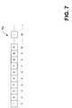
- FIG. 7is a block diagram that illustrates an example comprising various frames in an organization of picture types in display picture order, in accordance with one preferred embodiment of the of the disclosure.
- the STT described hereinis capable of a video-on-demand (VOD) service wherein a video program or movie, or any portion thereof can be received from a device, such as a server located remotely in a television network, for a period of time in any of several playback modes, including normal playback (e.g., regular viewing playback such as by selecting “Play” on a remote control device) and playback modes for trick mode viewing.
- VODvideo-on-demand
- trick mode viewing functionalityincludes operations that provide decoded pictures to a display device in one of several playback modes, including fast forward, slow forward, rewind, slow backward, and pause, and derivatives thereof.
- a playback mode instantiationis the display that results from providing the decoded pictures in one of these playback modes.
- a video decoderimplemented according to the preferred embodiments of the disclosure will cause the display of both fields without artifacts, such as motion jitter or discontinuous objects, rather than one vertical upscaled field of the picture, resulting in higher picture quality, among other benefits.
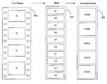
- FIG. 1is a block diagram depicting an example subscriber television system (STS) 100 , in accordance with one preferred embodiment of the disclosure.
- the STS 100includes a headend 204 and a set top terminal (STT) 510 that are coupled via a network 18 .
- the headend 204 and the STT 510cooperate to provide a user with television functionality including, for example, television programs, an interactive program guide (IPG), and/or video-on-demand (VOD), with support for normal playback modes and playback modes that correspond to trick modes, among other functionality.
- the headend 204may include one or more server devices for providing video, audio, and/or textual data to one or more STTs 510 , such as a VOD server 222 .
- the headend 204includes one or more encoders 206 .
- the encoder 206receives pictures from an image capture device 102 (e.g., a camera, optical scanner, etc.) or a repository device containing digitized pictures and encodes the pictures according to the syntax and semantics of a data compression (or encoding) method, such as MPEG-2, among others.
- the resulting compressed video streamis transmitted preferably as a digital transmission signal over the network 18 .
- the network 18may include any suitable infrastructure for communicating television services data including, for example, a cable television network or a satellite television network, among others.
- the television servicesare provided via the display device 120 , which may be a television set that receives a television signal as an interlaced video signal from STT 510 , a television set that receives a television signal as a progressive video signal, or a television set capable of receiving either of the video signal formats from the STT 510 .
- the encoder 206can be located external to the headend 204 in some embodiments or within the DHCT 510 .
- the video decoder 523may be located elsewhere in some embodiments, such as in the display device 120 .
- the STT 510can also receive analog transmission signals in addition to digital transmission signals.
- FIG. 2is a block diagram of portions of one example headend 204 that is configured to provide broadcast and video-on-demand (VOD) services, in accordance with one preferred embodiment.
- the overview of FIG. 2is equally applicable to one example hub, and the same elements and principles may be implemented at a hub instead of the headend 204 as described herein.
- the programming, services and other information from content providerscan be distributed according to a variety of mechanisms.
- the input signalsmay be transmitted from sources to the headend 204 via a variety of transmission paths, including satellites (not shown), and terrestrial broadcast transmitters and antennas (not shown).
- the headend 204can also receive content from a direct feed source via a direct line (not shown), application server (not shown), an image capture device 102 , among other sources.
- One or more componentssuch as the input source, the image capture device 102 , and the application server can be located external to the headend 204 or internal to the headend 201 as would be appreciated by one having ordinary skill in the art.
- the signals provided by the content or programming input sourcescan include a single media content instance or a multiplex that includes several media content instances. It will be understood that the headend 204 shown in FIG. 2 is merely illustrative and should not be construed as implying any limitations upon the scope of the present disclosure.
- the VOD application server 219 and a plurality of other application servers 220are connected to a digital network control system (DNCS) 223 via a high-speed network such as an Ethernet connection 232 .
- the VOD application server 219is responsible for reserving and configuring system resources needed to provide VOD services and for providing configuration and service data to a VOD application 563 ( FIG. 5A ).
- videois primarily referenced herein as the media content presented, it should be understood that various other types of media content associated with the video stream of a movie or television program are also considered to be within the scope of the preferred embodiments.
- one or more audio streams and/or one or more private data streamsmay be associated with the video stream of a movie or television program.
- the DNCS 223provides management, monitoring, and control of the network's elements and broadcast services provided to users.
- the DNCS 223uses a data insertion multiplexer 229 and a data QAM 230 to insert in-band broadcast file system (BFS) data into an MPEG-2 transport stream that is broadcast and received via the DHCT's communication interface 542 ( FIG. 5A ) and tuner system 545 ( FIG. 5A ).
- BFSbroadcast file system
- the DNCS 223also contains session management functionality, and preferably uses the Digital Storage Media Command and Control (DSM-CC) protocol to set up and maintain VOD sessions.
- DSM-CCDigital Storage Media Command and Control
- the DNCS 223preferably processes user to network (U-N) session signaling messages, manages allocation of session-related network resources, supports network management operations, acts as a point of contact to the network for the STTs 510 in the network 18 to establish individual sessions, and supports VOD services by providing the signaling interface to establish, maintain and release client initiated exclusive sessions.
- a QAM manager 236is included within the DNCS 223 , which is used to provide an interface for communications between the DNCS 223 and a QAM of the service (or QAM) groups 224 .
- a service application manager (SAM) server 225is a server component of a client-server pair of components, with the client component being located at the STT 510 ( FIG. 5A ). Together, the client-server SAM components provide a system in which the user can access services.
- BFSbroadcast file system
- the BFS server 228is a part of a broadcast file system that has a counterpart BFS client module 543 ( FIG. 5A ) in the STT 510 connected to the network 18 .
- the BFS server 228repeatedly sends data for applications on a data carousel (not shown) over a period of time in cyclical repeated fashion so that a STT 510 that is in need of reading any particular data file or parts thereof may receive it when requested by a user or one or more of its internal running processes.
- a VOD content manager 221is responsible for managing the content on the video pumps 211 of the VOD content servers 222 .
- the VOD application server 219controls both the VOD content manager 221 and the VOD content servers 222 and utilizes them to help deliver the video and audio streams that make up VOD services.
- the QAM modulators that comprise the QAM group 224receive the MPEG-2 transport streams from the VOD content servers 222 , convert them into encrypted RF signals at a specified frequency (channel), and transmit them to the STT 510 ( FIG. 5A ) via the network 18 .
- the quadrature phase-shift keying (QPSK) modem 226is responsible for transporting the out-of-band IP datagram traffic between the distribution headend 204 and a STT 510 ( FIG. 5A ). Data from the QPSK modem 226 is routed by a headend router 227 within the headend 204 .
- the headend router 227is also responsible for delivering upstream application traffic to the various application servers, for example application servers 219 and 220 .
- MPEG encoderssuch as encoder 206 are included for digitally encoding local programming or a real-time feed from the image capture device 102 , or the like.
- the encoder 206may provide compressed television programs and/or movies to reside on the VOD server 222 for storage in the VOD content server 222 .
- an encoder of like-functionalitycan be located externally to the headend 204 and the compressed television programs and/or movies can be provided in transportable media.
- the encoder 206can be implemented in hardware, software, or a combination of hardware and software.
- computationsare performed by digital signal processors (or media processors), not shown, residing in an encoder engine (not shown), using local memory (not shown) for fast access of the pictures being processed and as needed for input and output of pictures.
- the encoder 206detects that a picture is progressive by one of multiple methods and make annotations in the scan mode flag accordingly.
- Each line of a frameis processed in one of three different forms or any set resulting from the combination of the three forms.
- the first form of a lineis its original form, represented by the luminance (or luma) values of its corresponding pixels and their corresponding chrominance (or chroma) values.
- the second form of a linecorresponds to a candidate representing an interlaced scan picture and comprises assigning the corresponding pixel values of a low-pass filter (not shown) performed on a small set of consecutive lines from what would constitute a corresponding field.
- Each form of the line that is employed in the determination(i.e., could be form 1 only, the three forms, or any subset of the three forms) is processed further by using a first-order one-dimensional differential operator, representative of the discrete version of a first-order derivative, to obtain a profile of vertical edges in the line.
- the forms resulting from low pass filteringhelp eliminate impulsive noise and reinforce the original line.
- the actual edge position and corresponding strength of each edge in a form of a lineis found by non-maxima suppression of the response of the first order differential operator.
- the different forms of a lineare used to validate the existence of edges.
- the signature or amplitude of the vertical edge profile created as a result of these operationsis compared to the signature of the two adjacent lines (one immediately above and below) to obtain a matching score representative of a progressive scan format.
- the comparison to the second line above and second line belowserve as a matching score representative of an interlaced scan format.
- the matching scorecomprises of analyzing the vertical edge profiles by identifying the location of peaks, valleys, slopes, and the amplitude (which is a measure of contrast due to the first-order differential operation), or any combination thereof.
- a set of five consecutive lines(or parts of five consecutive lines) is analyzed at a top-most section of the picture, another set of five lines at the bottom, and two more sets of five lines equally spread apart towards the middle of the picture's ordinate.
- the final determination of whether the picture is of progressive or interlaced scanis determined from the analysis of each set of consecutive lines, including their determined candidacy and respective matching scores.
- a correlation functioncan be performed to small sets of consecutive lines or as a mechanism to reinforce the vertical edge profile analysis.
- all sets of consecutive and adjacent lines throughout the picturecan be selected in the analysis if designed into the computation and processing capabilities of the encoder.
- FIG. 3is a timing diagram 300 that illustrates the variety of scan formats of which a picture can be configured from its creation time to the time the picture is presented for output to the display device 120 , in accordance with several embodiments of the invention. Shown in the timing diagram 300 are some relevant components included in the process of capturing, conditioning, and delivering a picture for viewing by a user, including an image capture device 102 such as a camera or optical scanner, an encoder 206 , a video decoder 523 , and a display device 120 .
- the image capture device 102operates in an interlaced format (e.g., functionality includes a shutter mechanism that captures sequential snapshots of the scene as a top field and then the alternate lines as a bottom field, then as a top field, then as a bottom field, and so on) to provide the picture as an interlaced scan format 302 .
- the image capture device 102can be configured to capture the entire picture, thus providing a progressive scan format 304 .
- the picturesare provided to the encoder 206 from a configured scan operation of film produced by a film camera and the film exhibits a film format 306 .
- the encoder 206receives the picture in one of the aforementioned scan formats and encodes the picture for delivery over the STS 100 ( FIG. 1 ). As shown, the received picture can be encoded according to the compression methods of the encoder 206 that enables each individual picture to be encoded as an interlaced format 308 , a progressive format 310 , or as a combination of both, regardless of the scan format of each input picture to the encoder 206 . However, the encoder 206 is preferably optimized to make decisions to encode each input picture by exploiting its native scan format.
- an input picture that was “born” as a progressive scan format 304can be encoded as an interlaced scan format 308 for any of a number of reasons (e.g., if 3:2 pulldown was performed a priori in transmission, due to editing, or to preserve close-caption data with the proper picture).
- a picture received as input to the encoder 206 and received in the interlaced scan format 302can be encoded as progressive 310 because that is how the encoder 206 was programmed to operate.
- the encoder 206could be designed to encode progressive pictures for memory organization purposes, because it first de-interlaces the incoming interlaced pictures, or because it assumes that the compressed video stream will be displayed in a display device that accepts a progressive television signal.
- the picture sequence header 402includes information for the video decoder 523 , such as the MPEG profile and level, whether the chroma format is 4:2:0 or 4:2:2, the size of the picture, and the aspect ratio of the pixels.
- the picture sequence header 402also includes a scan mode flag 403 that is inserted by the encoder 206 upon detecting the scan format of the source picture (i.e., from the image capture device 102 ).
- the scan mode flag 403can be in each picture header or sequence header (and sequence headers are repeated periodically), or the scan mode flag 403 can be disposed in a separate file by itelf, or integrated in a file with annotations, or any combination of the above.
- the tuner system 545enables the STT 510 to tune to downstream content (i.e., data, video, and/or audio) transmissions, thereby allowing a user to receive digital and/or analog content via the subscriber television system 100 .
- the tuner system 545includes, in one implementation, an out-of-band tuner for bidirectional quadrature phase shift keying (QPSK) data communication and a quadrature amplitude modulation (QAM) tuner (in band) for receiving television signals.
- QPSKquadrature phase shift keying
- QAMquadrature amplitude modulation
- a receiver 546receives externally-generated user inputs or commands from an input device such as, for example, a remote control device 580 .
- FIG. 5Bis a schematic diagram of the example remote control device 580 shown in FIG. 5A , in accordance with one preferred embodiment of the disclosure.
- Pause button 585is buttons used by a user to activate playback mode operations (e.g., trick modes) during displayed programming.
- a slow forward playback and slow reverse playback(not shown) in remote control 580 may activate respective slow playback modes.
- Many alternative methods of providing user inputmay be used including a remote control device with different buttons and/or button layouts, a keyboard device, a voice activated device, etc. The embodiments described herein are not limited by the type of device used to provide user input.
- the STT 510may include one or more wireless or wired interfaces, also called communication ports 574 , for receiving and/or transmitting data to other devices.
- the STT 510may feature USB (Universal Serial Bus), Ethernet, IEEE-1394, serial, and/or parallel ports, etc.
- the STT 510may also include an analog video input port for receiving analog video signals.
- the STT 510includes a signal processing system 514 , which comprises a demodulating system 513 and a transport demultiplexing and parsing system 515 (herein demultiplexing system 515 ) for processing broadcast media content and/or data.
- a signal processing system 514which comprises a demodulating system 513 and a transport demultiplexing and parsing system 515 (herein demultiplexing system 515 ) for processing broadcast media content and/or data.
- One or more of the components of the signal processing system 514can be implemented with software, a combination of software and hardware, or preferably in hardware.
- the demodulating system 513comprises functionality for demodulating analog and/or digital transmission signals. For instance, the demodulating system 513 can demodulate a digital transmission signal in a carrier frequency that was modulated, among others, as a QAM-modulated signal.
- the demultiplexing system 515When tuned to a carrier frequency corresponding to an analog TV signal, the demultiplexing system 515 is bypassed and the demodulated analog TV signal that is output by the demodulating system 513 is instead routed to an analog video decoder 516 .
- the analog video decoder 516converts the analog TV signal into a sequence of digitized pictures and their respective digitized audio.
- the digitized pictures and respective audio output by the analog video decoder 516are presented at the input of a compression engine 517 .
- the compression engine 517multiplexes the audio and video compressed streams, and in some embodiments, a file comprising of annotations and auxiliary information, into a transport stream, such as an MPEG-2 transport stream. Furthermore, the compression engine 517 can preferably compress audio and video corresponding to more than one program in parallel (e.g., two tuned analog TV signals when STT 510 has multiple tuners) and multiplex the respective audio and video compressed streams into a single transport stream. The output of compressed video streams and/or transport streams produced by the compression engine 517 is input to the signal processing system 514 .
- the compression engine 517multiplexes the audio and video compressed video streams, and in some embodiments, a file comprising of annotations and auxiliary information, into a transport stream, such as an MPEG-2 transport stream. Furthermore, the compression engine 517 can preferably compress audio and video corresponding to more than one program in parallel (e.g., two tuned analog TV signals when STT 510 has multiple tuners) and multiplex the respective audio and video compressed streams into a single transport stream. The output of compressed video streams and/or transport streams produced by the compression engine 517 is input to the signal processing system 514 .
- the digital compressed video streams output by the compression engine 517 corresponding to a video streamare routed to the demultiplexing system 515 .
- the demultiplexing system 515parses (i.e., reads and interprets) the transport stream generated by the compression engine 517 without disturbing its content and deposits the transport stream into memory 549 .
- the processor 544causes the transport stream in memory 549 to be transferred to the storage device 573 .
- the demultiplexing system 515outputs to memory 549 ancillary data in the form of a table or data structure comprising the relative or absolute location of the beginning of certain pictures in the compressed media content stream for the video stream for facilitating retrieval during future operations. In this way, playback mode operations such as fast forward and rewind to a location in the compressed video stream can be attained. Additional pertinent data such as to assist in decoding and output of pictures during trick modes is also written in the tables, as described below.
- Parsing capabilities within the demultiplexing system 515 of the signal processing system 514allow for interpretation of picture sequence headers and picture headers, and annotating their locations within their respective compressed video stream as well as other useful information for future retrieval and support of trick mode operations from a storage device 573 , as described below.
- a compressed video stream(e.g., corresponding to a TV program episode or show) that is received via a tuned analog transmission channel can be output as a transport stream by the signal processing system 514 and presented as input for storage in the storage device 573 via a communication interface 575 .
- the packetized compressed video streamscan be also output by the signal processing system 514 and presented as input to a media engine 522 for decompression by the video decoder 523 and the audio decoder 525 for subsequent output to the display device 120 ( FIG. 1 ).
- a plurality of compression engines 517may be used to simultaneously compress a plurality of analog video streams.
- a single compression engine 517 with sufficient processing capabilitiesmay be used to compress a plurality of analog video streams.
- Compressed digital versions of respective analog video streamsmay be routed to the hard disk 501 of the storage device 573 .
- Data annotations for each of the video streamsmay be performed to facilitate future retrieval of the video streams from the storage device 573 and to assist in decoding and output of pictures during trick modes.
- only a subset of the total number of compressed digital video signalsmay be routed to the storage device 573 .
- Any of the received video streamscan also be routed simultaneously to the media engine 522 for decoding and subsequent presentation via the display device 120 ( FIG. 1 ).
- functionality of the compression engine 517may be in the STT 510 as described, in the headend 204 ( FIG. 2 ), or in other locations that produced the video streams for transmission and/or to store in the VOD server 222 ( FIG. 2 ).
- the demultiplexing system 515also includes transport demultiplexing, such as for MPEG-2.
- transport demultiplexingsuch as for MPEG-2.
- the following description of the STT 510 corresponding to digital transmissionwill be understood in the context of MPEG-2 transport, with the understanding that other standards and/or compression methodologies are within the scope of the preferred embodiments.
- the demultiplexing system 515When tuned to carrier frequencies carrying a digital transmission signal, the demultiplexing system 515 enables the separation of packets of data, corresponding to the desired video streams, for further processing. Concurrently, the demultiplexing system 515 precludes further processing of packets in the multiplexed transport stream that are irrelevant or not desired such as, for example, packets of data corresponding to other video streams.
- the components of the signal processing system 514are preferably capable of QAM demodulation, forward error correction, demultiplexing of MPEG-2 transport streams, and parsing of packetized elementary streams and elementary streams.
- the signal processing system 514further communicates with the processor 544 via interrupt and messaging capabilities of the STT 510 .
- the processor 544annotates the location of pictures within the compressed video stream as well as other pertinent information such as the type of scan format detected. The annotations by the processor 544 enable normal playback or other playback modes of the stored compressed video stream.
- the demultiplexing system 515parses (i.e., reads and interprets) compressed video streams to interpret picture sequence headers and picture headers, and deposits a transport stream carrying compressed video streams into memory 549 .
- the processor 544causes the transport stream to be transferred from memory 549 to the storage device 573 via the communication interface 575 .
- the processor 544interprets the data output by the signal processing system 514 and generates ancillary data in the form of a table or data structure comprising the relative or absolute location of the beginning of certain pictures in the compressed video stream.
- ancillary datais used to facilitate the retrieval of desired video data during future operations and to assist in decoding and output of pictures during trick modes.
- the scan formatis annotated as a result of a scan format detection procedure, as described below.
- a compressed video stream corresponding to a tuned carrier frequency carrying a digital transmission signalcan be output as a transport stream by the signal processing system 514 and presented as input for storage in the storage device 573 via the communication interface 575 .
- the packetized compressed video streamscan be also output by the signal processing system 514 and presented as input to the media engine 522 for decompression by the video decoder 523 and the audio decoder 525 .
- the signal processing system 514may include other components not shown, including memory, decryptors, samplers, digitizers (e.g. analog-to-digital converters), and multiplexers, among others. Further, other embodiments will be understood, by those having ordinary skill in the art, to be within the scope of the preferred embodiments of the present invention.
- analog signalse.g., NTSC
- NTSCmay bypass one or more elements of the signal processing system 514 and may be forwarded directly to the output/display system 548 .
- Outputs presented at corresponding next-stage inputs for the aforementioned signal processing flowmay be connected via accessible memory 549 in which an outputting device stores the output data and from which an inputting device retrieves it.
- Outputting and inputting devicesmay include the analog video decoder 516 , the compression engine 517 , the media engine 522 , the signal processing system 514 , and components or sub-components thereof.
- a plurality of tuners and respective demodulating systems 513 , demultiplexing systems 515 , and signal processing systems 514may simultaneously receive and process a plurality of respective broadcast digital video streams.
- a single demodulating system 513 , a single demultiplexing system 515 , and a single signal processing system 514each with sufficient processing capabilities may be used to process a plurality of digital video streams.
- a first tuner in tuning system 545receives an analog video signal corresponding to a first video stream and a second tuner simultaneously receives a digital compressed video stream corresponding to a second video stream.
- the first video streamis converted into a digital format.
- the second video stream and/or a compressed digital version of the first video streamare routed to the hard disk 501 of the storage device 573 .
- Data annotations for each of the two streamsare performed to facilitate future retrieval of the video streams from the storage device 573 and to assist in decoding and output of pictures during trick modes.
- the first video stream and/or the second video streammay also be routed to media engine 522 for decoding and subsequent presentation via the display device 120 ( FIG. 1 ).
- video streamsare received in the STT 510 via the communications interface 542 and stored in a temporary memory cache (not shown).
- the temporary memory cachemay be a designated section of memory 549 or an independent memory attached directly to the communication interface 542 .
- the temporary cacheis implemented and managed to enable content transfers to the storage device 573 .
- the fast access time and high data transfer rate characteristics of the storage device 573enable media content to be read from the temporary cache and written to the storage device 573 in a sufficiently fast manner. Multiple simultaneous data transfer operations may be implemented so that while data is being transferred from the temporary cache to the storage device 573 , additional data may be received and stored in the temporary cache.
- the storage device 573is preferably a hard disk drive but may in an alternative embodiment be any type of magnetic, optical, or semiconductor based storage device.
- the storage device 573is preferably internal to the STT 510 , coupled to a common bus 505 through the communication interface 575 .
- the communication interface 575is preferably an integrated drive electronics (IDE) or small computer system interface (SCSI), although another interface such as, for example, IEEE-1394 or USB, among others, may be used.
- IDEintegrated drive electronics
- SCSIsmall computer system interface
- the storage device 573can be externally connected to the STT 510 via a communication port 574 .
- the communication port 574may be, for example, an IEEE-1394, a USB, a SCSI, or an IDE, among others.
- the storage device 573preferably includes at least one hard disk 501 and a controller 579 .
- a PVR application 577in cooperation with the operating system 553 and the device driver 511 , effects, among other functions, read and/or write operations to the storage device 573 .
- the device driver 511is a software module preferably resident in the operating system 553 .
- the device driver 511under management of the operating system 553 , communicates with the storage device controller 579 to provide operating instructions for the storage device 573 .
- the controller 579receives the operating instructions from the device driver 511 and implements those instructions to cause read and/or write operations to the hard disk 501 .
- references to write and/or read operations to the storage device 573will be understood to include operations to the medium or media of the storage device 573 unless indicated otherwise.
- references to write and/or read operations to the storage device 573will be understood to include operations to the medium or media of the storage device 573 unless indicated otherwise.
- conventional device drivers and device controllersare well known to those of ordinary skill in the art, further discussion of the detailed working of each will not be described further here.
- the operating system 553in cooperation with the device driver 511 , communicates with the storage device controller 579 to format the hard disk 501 .
- the operating system 553 , device driver 511 , and controller 579cooperate to create a file allocation table (FAT).
- the FAT 504is where the operating system 553 stores the information about the hard disk clusters and the files associated with those clusters.
- the operating system 553can determine where a file's data is located by using the directory entry for the file and file allocation table (FAT) entries.
- the directory entrygives information about a directory such as its related files and subdirectories.
- a FAT entrydescribes the physical locations of data for a video stream file (i.e.
- the FAT 504also keeps track of which clusters are free, or open, and thus available for use.
- the operating system 553in cooperation with the device driver 511 , queries the FAT 504 for an available cluster to begin writing the video stream.
- the PVR application 577creates a video stream file and video stream file name for the video stream to be downloaded.
- the operating system 553in cooperation with the device driver 511 , checks the FAT 504 for an available, or writeable, cluster to write the video stream to.
- the PVR application 577effects the device driver 511 , through communication with the operating system 553 , to cause the controller 579 to write the downloaded video stream to the available cluster under a particular video stream file name.
- the FAT 504is then updated with the new video stream file name corresponding to the available cluster.
- the operating system 553queries the FAT 504 for the location of another available cluster to continue writing the video stream to hard disk space. Upon finding another cluster, the FAT 504 is updated to keep track of which clusters are linked to store a particular video stream under the given video stream file name.
- all these factors coupled with the processing and computing capabilities of STT 510determine whether a picture may have to be displayed repeatedly over consecutive picture display intervals to effect the speed of a first type of trick mode operation.
- a second type of trick mode operatione.g., very slow forward playback
- the processing and computing capabilities of STT 510have virtually no bearing on how much processing can be performed to output a picture for display.
- the STT 510receives user input requesting playback mode functionality (herein described as a playback mode request).
- the user inputmay be provided via, for example, the remote control device 580 .
- a playback mode request for a compressed video presentation stored in the storage device 573may specify information that includes the playback mode, direction of playback, entry point of playback with respect to the beginning of the compressed video presentation, and playback speed, if applicable.
- activation of a playback modemay also specify the duration of the mode.
- Playback speedis applicable to playback modes other than the pause display and may be specified as a factor or proportion of the normal playback speed. Speed may be implied by how long the key is pressed by a user or via visual feedback presented on the screen.
- Direction of playbackmay also be implied by which key the user pressed.
- the entry point for playbackis relative to the beginning of the compressed video presentation stored in the storage device 573 and may be specified in a number of different ways according to the predetermined format for a request's specification.
- the entry point in the request for which to start playbackmay be specified in relation to the beginning of the video presentation as elapsed normal playback time, number of pictures, or number of certain types of pictures.
- the processor 544In response to a request for retrieval and playback of a compressed video stream for which the playback mode is a “pause-display” and for which the entry point is at the beginning of the compressed video stream, the processor 544 , in communication generally with the device driver 511 and the storage device controller 579 and the demultiplexing system 515 , effects retrieval of compressed video data from the storage device 573 that correspond to one or more video streams specified in the request.
- one or more compressed video streamsare deposited in an output cache (not shown) in the storage device 573 , transferred to memory 549 , and then the compressed video streams are routed to the video decoder 523 and audio decoder 525 for decoding and delivery to the display device 120 ( FIG. 1 ).
- the compressed video streamsare retrieved and routed from the hard disk 501 to the video decoder 523 and the audio decoder 525 simultaneously, and then further processed for subsequent presentation via the display device 120 .
- the processor 544In response to a request for playback modes that are not “pause-display”, or for which the entry point is not at the beginning of the compressed video stream, the processor 544 in communication generally with the device driver 511 and the storage device controller 579 reads information in the respective entry in the index table 502 for the requested compressed video stream to retrieve annotation data from storage device 573 that corresponds to the requested video streams specified in the request. Immediately thereafter under program control, the processor 544 retrieves the program information file 503 from the storage device 573 and interprets the program information file 503 to compute the entry point location for which to fulfill the specified playback mode in the request. In a preferred embodiment, information pertaining to the characteristics of the compressed video stream is contained in the program information file 503 and interpreted to fulfill the specified playback mode in the request.
- communication between the headend 204 ( FIG. 2 ) and the STT 510 via the communications interface 542allows the STT 510 to establish a session with the VOD server 222 ( FIG. 2 ) at the headend 204 to allow the STT 510 to receive a movie through a VOD service. While a movie or television program is received by the STT 510 and output for display to a user, the user may invoke a playback mode other than normal playback.
- the headend 204Responsive to the user's input, and under the established session requiring a direct connection between STT 510 and the VOD server 222 , the headend 204 receives and interprets the user's request for a trick mode operation, and thereafter transmits the compressed video (or parts thereof) from the VOD server 222 with a “trick mode” flag in the video bitstream that specifies to the video decoder that its management procedures of the buffer 562 wherein the compressed video stream is deposited is to be performed in a different manner.
- a trick mode flagfurther allows the STT 510 to enter an output operation mode in which the last fully reconstructed picture for display in memory, possibly composed from multiple pictures and/or processed through a deinterlacer (not shown), continues to be retained in memory (again the memory that is local to the video decoder 523 ) and fed repeatedly for output over consecutive picture display intervals.
- pictures provided during trick modes through the tuned channel corresponding to a VOD servicetypically require that a reconstructed picture be displayed repeatedly over consecutive picture display intervals, although not necessarily so.
- a video program or movieresides in a VOD server 222 ( FIG. 2 ) in the headend 204 ( FIG. 2 ) with its respective annotations, including the scan mode flag for corresponding pictures or set of pictures according to the implementation of picture scan detection as explained above.
- a file containing the annotationscan be transmitted during the initial phase of a VOD session, soon after a viewer first instantiates the VOD service by requesting a movie that resides in the VOD server 222 . Upon reception, the file is stored in memory 549 or the storage device 573 of the STT 510 .
- both a top field and a bottom fieldare output.
- one of the two fields required for outputmay be from the reconstruction of a first compressed picture while the other field may be from the reconstruction of a second compressed picture.
- progressive picturessuch as 24 Hertz film source, often undergo processing that converts the signal into an interlaced scan format by extracting the equivalent lines corresponding to each field from the progressive picture and according to a predetermined procedure (e.g., 3:2 pulldown), repeating a field in two of the consecutive interlaced pictures produced as an interlaced signal.
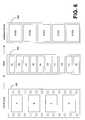
- FIG. 6is a schematic diagram that is used to illustrate 3:2 pull down, in accordance with one preferred embodiment of the invention.
- the first block column 602shows four frames of film, for example, frames A, B, C, and D.
- the second block column 604illustrates the pulldown operation of 3 or 2 fields per frame.
- the third column block 606shows the interlaced frames created from the fields of column 604 for display on the display device 120 ( FIG. 1 ).
- the first frame of film, frame Ais placed on 3 fields of video, for example, a repeated field A 1 and field A 2 .
- the next frame of film, frame Bis placed on 2 fields, for example fields B 1 and B 2 .
- the next frame of film, frame Cis placed on three fields, for example a repeated field C 2 , and field C 1 , and so on.
- 24 Hz filmis converted to 60 Hz interlaced pictures by the process of 3:2 pull-down, shown in FIG. 6 , in which the equivalent of the top and bottom field in each of four progressive pictures 602 are used to produce five corresponding interlaced frames 606 .
- the equivalent of the top and bottom field in each of four progressive pictures 602are used to produce five corresponding interlaced frames 606 .
- both fields of a progressive scan pictureare output if the video decoder 523 detects that both fields indeed correspond to the same picture at creation time.
- the video decoderascertains so, either via a scan detection method or from the scan mode flag, both fields of the picture are output. Otherwise two pictures (i.e., an additional picture) are decoded by the video decoder 523 to obtain a respective field from each and composite the progressive picture that was captured at the time of picture creation. This is the case when the first picture decoded is either A 1 /B 2 or B 1 /C 2 in 606 .
- the video decoder 523running in the operating mode to effect trick modes, in one preferred embodiment invokes a deinterlacer mechanism that employs using the information in one or more fields from past pictures in display order and/or one or more fields from future pictures in display order, to compose the fields of the picture to be output.
- the video decoder 523decodes and reconstructs at least one field from a set of past and future pictures and also decodes both fields of the required picture to be displayed repeatedly over consecutive picture display intervals. From the multiple decoded fields, the video decoder 523 , or a deinterlacer (not shown), generates a de-interlaced (or progressive picture approximation) version of the pictures to be output during the trick modes.
- an optical scannercan be used to digitize pictures from film.
- the optical scanning operationtypically results in digital pictures created with a progressive scan format, although pictures could be created from film with an interlaced scan format.
- the video decoder 523when the video decoder 523 is effecting a trick mode, if the picture is of a film nature, as the video decoder 523 ascertains by examining the scan mode flag in the picture sequence header over time, and the video decoder 523 further ascertains from the video bitstream that the pictures were compressed as progressive pictures, then the video decoder 523 can assume that both fields in a compressed frame correspond to the same instance of time at the creation time of the corresponding pictures and proceed to display both fields during fast forward, slow forward, rewind, slow backward, or pause operations.
- the scan mode flagmay also be used to assist the video decoder 523 in employing 3:2 pulldown, as shown in FIG. 6 , when the video bitstream is coded as progressive pictures, in addition to or in lieu of a repeat field flag that could be provided in a header of the compressed video streams.
- the picture displayed at the one second of time intervalshould be the picture at position 90 .
- the picture positionwould be at 60 at the end of two seconds of time, at 3 ⁇ faster than normal play, fast forward, the picture position would be at position 180 .
- the typical goalis to provide a display of pictures such that at the time when the 30 th and 60 th pictures would ordinarily be displayed, the 90th and the 180 th pictures are respectively displayed to effect the sensation of fast forward.
- One mechanism to achieve thiswould be to skip pictures at various intervals, such as presenting the first picture (at position 1 ), and then the picture at position 4 , and so forth.
- the organization of picture types (I, P or B) and the dependencies on referenced pictures through the sequence of pictures in display ordercauses the need for some pictures to be decoded but not displayed so that they can serve as a reference picture.
- Thisimposes a burden on the processing capabilities of the STT 510 and/or video decoder 523 .
- another mechanismwould be to display certain pictures repeatedly over multiple consecutive picture display intervals to alleviate the processing burden in STT 510 and/or video decoder 523 .
- the I picturesonly could be retrieved from the storage device 573 ( FIG. 5A ) (or transmitted from the VOD server 222 , FIG. 2 ), decoded by video decoder 523 but displayed repeatedly over five consecutive picture display intervals.
- the first method of 3 ⁇ faster playback implementationwould have decoded every I and every interspersed P picture and thus require a total of six I pictures and 24 P pictures displayed over one second, a Method A (described below) only requires the six I pictures to be decoded but each displayed repeatedly over five consecutive picture display intervals.
- each I pictureis displayed for five picture display intervals because it replaces four P pictures (and its prior display instance sums to five).
- the fast forward sensationis the same to the viewer but demands less computation and processing from the STT 510 and by the video decoder 523 .
- the first methodwould require that every other P picture be displayed, assuming picture organization 700 .
- other P pictures not required to be displayedwould have to be decoded to serve as a reference picture to the P picture that is required to be output. Consequently, the method of decoding and displaying I pictures only while repeatedly outputting the I picture over consecutive picture display intervals can save considerable processing and computation. Since for 6 ⁇ speed the 180 th picture must be displayed at the end of the first second of time, assuming the picture organization 700 of FIG. 7 , only 12 I pictures would be decoded, some output over two consecutive picture display intervals.
- the scan mode flagcarries specific information as a result of the detection method described above and/or is different as explained above in that it can have a progressive affirmative value yet the picture (or set of pictures) can be coded as interlaced pictures.
- Reference to a film flag throughout this disclosureshould be interpreted as the source scan mode flag.
- the “Coded” heading in Table 1signifies the manner in which the picture was encoded by a compression engine (e.g., encoder 206 ), either as a progressive picture (frame) or as two fields (fields).
- “Television Type”signifies the scan format of the television driven by the STT 510 , either an interlaced scan TV (I) or a progressive scan TV (P).
- de-interlace 6 P Ifields or non- Yes I Yes Yes Detect fields from the same picture in a film frame rate single picture or two consecutive pictures.
- de-interlace 7 P Poriginal frame Yes P Don't care No Display decoded picture as is; no rate at capture
- artifact 8 P Poriginal frame Yes I Don't care No Display decoded picture as is; no rate at capture
- each I picture from an interlaced scan sourceis deinterlaced prior to outputting.
- the deinterlacing procedurecan merely employ the information in both fields and be assisted by the scan mode detection procedure (e.g., based on vertical profile analysis) described previously to adjust the edges from line to line in conjunction with limited low pass filtering.
- the deinterlacing procedureuses the information of at least one extra picture that is also required to be output.
- one or more pictures not required to be outputcan be decoded for deinterlacing purposes only, depending on the processing capabilities of STT 510 ( FIG. 5A ).
- a field of at least one P picturepreferably (but not necessarily) the subsequent P picture to the I picture (in the picture display order) is employed for deinterlacing.
- fields from one or both closest pictures to the I picture in the picture display ordercan be employed if the compute and processing capabilities of the STT 510 and video decoder 523 ( FIG. 5A ) allow so.
- the scan format detection methodis performed in the decoded I picture.
- the subsequent picture in display orderis decoded to obtain the corresponding field.
- deinterlacingcan be performed as described above for an I picture from an interlaced scan source.
- the STT 510 ( FIG. 5A ) and video decoder 523 ( FIG. 5A )likely have ample compute and processing capabilities.
- deinterlacingis required to be performed to reconstruct a deinterlaced version of a picture
- the closest picture to a picture in display orderis decoded to obtain the required fields for input to the deinterlacing procedure.
- the adjacent pictureis required to be decoded for cases 5 and 6 of Table 1 to properly reconstruct a progressive picture, the adjacent picture is decoded and the proper progressive picture composed from fields of the two decoded pictures.
- both fields of a pictureare always displayed for pause and slow speed trick modes but for fast speed trick modes only one field of the picture is displayed by displaying it twice or by first scaling it to the size of the complete picture (i.e., two fields size) with the upscaling capabilities in the display/output system 548 .
- the video decoder 523( FIG. 5A ), compression engine 517 ( FIG. 5A ), and the encoder 206 ( FIG. 2 ) can be implemented in hardware, software, firmware, or a combination thereof.
- the video decoder 523 , compression engine 517 , and the encoder 206are each implemented in a digital signal processor or media processor device.
- software and firmwarethat is stored in a memory and that is executed by a suitable instruction execution system is employed to effect the decoding operations.
- the video decoder 523 , compression engine 517 , and the encoder 206may each be implemented with any or a combination of the following technologies, which are all well known in the art: a discrete logic circuit(s) having logic gates for implementing logic functions upon data signals, an application specific integrated circuit (ASIC) having appropriate combinational logic gates, a programmable gate array(s) (PGA), a field programmable gate array (FPGA), etc.
- ASICapplication specific integrated circuit
- PGAprogrammable gate array
- FPGAfield programmable gate array
- the video decoder 523 , compression engine 517 , and the encoder 206which each can comprise an ordered listing of executable instructions for implementing logical functions, can be embodied in any computer-readable medium for use by or in connection with an instruction execution system, apparatus, or device, such as a computer-based system, processor-containing system, or other system that can fetch the instructions from the instruction execution system, apparatus, or device and execute the instructions.
- a “computer-readable medium”can be any means that can contain, store, communicate, propagate, or transport the program for use by or in connection with the instruction execution system, apparatus, or device.
- the computer readable mediumcan be, for example but not limited to, an electronic, magnetic, optical, electromagnetic, infrared, or semiconductor system, apparatus, device, or propagation medium. More specific examples (a nonexhaustive list) of the computer-readable medium would include the following: an electrical connection (electronic) having one or more wires, a portable computer diskette (magnetic), a random access memory (RAM) (electronic), a read-only memory (ROM) (electronic), an erasable programmable read-only memory (EPROM or Flash memory) (electronic), an optical fiber (optical), and a portable compact disc read-only memory (CDROM) (optical).
- an electrical connectionhaving one or more wires
- a portable computer diskettemagnetic
- RAMrandom access memory
- ROMread-only memory
- EPROM or Flash memoryerasable programmable read-only memory
- CDROMportable compact disc read-only memory
- the computer-readable mediumcould even be paper or another suitable medium upon which the program is printed, as the program can be electronically captured, via for instance optical scanning of the paper or other medium, then compiled, interpreted or otherwise processed in a suitable manner if necessary, and then stored in a computer memory.
Landscapes
- Engineering & Computer Science (AREA)
- Multimedia (AREA)
- Signal Processing (AREA)
- Television Signal Processing For Recording (AREA)
Abstract
Description
- a) The storage location of each of the sequence headers;
- b) The storage location of each picture start code;
- c) The type of each picture (I, P, or B);
- d) The real time of when each picture was stored; and/or
- e) The scan format detected for each picture or set of pictures (e.g., a GOP).
| TABLE 1 | ||||||||
| Effect of how | Effect of | |||||||
| picture is | Television | Television | Requires | Type of Processing Required and | ||||
| Source | Coded | Coded | Type | Type | Processing? | Artifact Avoided | ||
| 1 | I | I (fields) | Don't care | I | Yes | Yes | Must de-interlace to avoid motion jitter |
| 2 | I | frame | Don't care | I | Yes | Yes | Must de-interlace to avoid motion jitter |
| 3 | I | I (fields) | Don't care | P | Yes | Yes | Must de-interlace to avoid displaying |
| discontinuities in objects' contours | |||||||
| 4 | I | frame | Don't care | P | Yes | Yes | Must de-interlace to avoid displaying |
| discontinuities in objects' contours | |||||||
| 5 | P | I (fields) or non- | Yes | P | Yes | Yes | Detect fields from the same picture in a |
| film frame rate | single picture or two consecutive | ||||||
| pictures. Alternative is to de-interlace | |||||||
| 6 | P | I (fields) or non- | Yes | I | Yes | Yes | Detect fields from the same picture in a |
| film frame rate | single picture or two consecutive | ||||||
| pictures. Alternative is to de-interlace | |||||||
| 7 | P | P (original frame | Yes | P | Don't care | No | Display decoded picture as is; no |
| rate at capture) | artifact | ||||||
| 8 | P | P (original frame | Yes | I | Don't care | No | Display decoded picture as is; no |
| rate at capture) | artifact | ||||||
Claims (22)
Priority Applications (4)
| Application Number | Priority Date | Filing Date | Title |
|---|---|---|---|
| US10/891,318US8600217B2 (en) | 2004-07-14 | 2004-07-14 | System and method for improving quality of displayed picture during trick modes |
| PCT/US2005/024706WO2006019742A1 (en) | 2004-07-14 | 2005-07-08 | System and method for playback of digital video pictures in compressed streams |
| EP05764529.3AEP1782624B1 (en) | 2004-07-14 | 2005-07-08 | System and method for playback of digital video pictures in compressed streams |
| CA2573906ACA2573906C (en) | 2004-07-14 | 2005-07-08 | System and method for playback of digital video pictures in compressed streams |
Applications Claiming Priority (1)
| Application Number | Priority Date | Filing Date | Title |
|---|---|---|---|
| US10/891,318US8600217B2 (en) | 2004-07-14 | 2004-07-14 | System and method for improving quality of displayed picture during trick modes |
Publications (2)
| Publication Number | Publication Date |
|---|---|
| US20060013568A1 US20060013568A1 (en) | 2006-01-19 |
| US8600217B2true US8600217B2 (en) | 2013-12-03 |
Family
ID=34980279
Family Applications (1)
| Application Number | Title | Priority Date | Filing Date |
|---|---|---|---|
| US10/891,318Active2029-10-22US8600217B2 (en) | 2004-07-14 | 2004-07-14 | System and method for improving quality of displayed picture during trick modes |
Country Status (4)
| Country | Link |
|---|---|
| US (1) | US8600217B2 (en) |
| EP (1) | EP1782624B1 (en) |
| CA (1) | CA2573906C (en) |
| WO (1) | WO2006019742A1 (en) |
Cited By (1)
| Publication number | Priority date | Publication date | Assignee | Title |
|---|---|---|---|---|
| US9998750B2 (en) | 2013-03-15 | 2018-06-12 | Cisco Technology, Inc. | Systems and methods for guided conversion of video from a first to a second compression format |
Families Citing this family (68)
| Publication number | Priority date | Publication date | Assignee | Title |
|---|---|---|---|---|
| CA2394352C (en)* | 1999-12-14 | 2008-07-15 | Scientific-Atlanta, Inc. | System and method for adaptive decoding of a video signal with coordinated resource allocation |
| US7274857B2 (en)* | 2001-12-31 | 2007-09-25 | Scientific-Atlanta, Inc. | Trick modes for compressed video streams |
| US7839930B2 (en)* | 2003-11-13 | 2010-11-23 | Microsoft Corporation | Signaling valid entry points in a video stream |
| US8582659B2 (en) | 2003-09-07 | 2013-11-12 | Microsoft Corporation | Determining a decoding time stamp from buffer fullness |
| US8107531B2 (en)* | 2003-09-07 | 2012-01-31 | Microsoft Corporation | Signaling and repeat padding for skip frames |
| US8213779B2 (en)* | 2003-09-07 | 2012-07-03 | Microsoft Corporation | Trick mode elementary stream and receiver system |
| US8345754B2 (en)* | 2003-09-07 | 2013-01-01 | Microsoft Corporation | Signaling buffer fullness |
| US7961786B2 (en)* | 2003-09-07 | 2011-06-14 | Microsoft Corporation | Signaling field type information |
| US7924921B2 (en)* | 2003-09-07 | 2011-04-12 | Microsoft Corporation | Signaling coding and display options in entry point headers |
| US7724827B2 (en)* | 2003-09-07 | 2010-05-25 | Microsoft Corporation | Multi-layer run level encoding and decoding |
| US7852919B2 (en)* | 2003-09-07 | 2010-12-14 | Microsoft Corporation | Field start code for entry point frames with predicted first field |
| US7966642B2 (en)* | 2003-09-15 | 2011-06-21 | Nair Ajith N | Resource-adaptive management of video storage |
| US7519274B2 (en) | 2003-12-08 | 2009-04-14 | Divx, Inc. | File format for multiple track digital data |
| US8472792B2 (en) | 2003-12-08 | 2013-06-25 | Divx, Llc | Multimedia distribution system |
| WO2006018798A1 (en)* | 2004-08-13 | 2006-02-23 | Koninklijke Philips Electronics, N.V. | System and method for compression of mixed graphic and video sources |
| US8768150B2 (en)* | 2004-10-08 | 2014-07-01 | Broadcom Corporation | Method and system for trick mode support in a motion adaptive deinterlacer with inverse telecine |
| US20060104356A1 (en)* | 2004-11-15 | 2006-05-18 | Microsoft Corporation | Timing for decoder buffer examination |
| US7675872B2 (en) | 2004-11-30 | 2010-03-09 | Broadcom Corporation | System, method, and apparatus for displaying pictures |
| US7859574B1 (en)* | 2005-07-19 | 2010-12-28 | Maxim Integrated Products, Inc. | Integrated camera image signal processor and video encoder |
| US20070019925A1 (en)* | 2005-07-21 | 2007-01-25 | Macinnis Alexander | Systems, methods, and apparatus for trick mode |
| US20070092007A1 (en)* | 2005-10-24 | 2007-04-26 | Mediatek Inc. | Methods and systems for video data processing employing frame/field region predictions in motion estimation |
| KR100817052B1 (en)* | 2006-01-10 | 2008-03-26 | 삼성전자주식회사 | Video signal processing device and video signal processing method that does not require high memory bandwidth |
| JP2007214786A (en)* | 2006-02-08 | 2007-08-23 | Toshiba Corp | Portable imaging device |
| EP1999883A4 (en) | 2006-03-14 | 2013-03-06 | Divx Llc | Federated digital rights management scheme including trusted systems |
| EP3901779B1 (en) | 2007-01-05 | 2022-10-26 | DivX, LLC | Video distribution system including progressive playback |
| KR20080072159A (en)* | 2007-02-01 | 2008-08-06 | 엘지전자 주식회사 | File management method and data recorder |
| US8189107B1 (en)* | 2007-03-12 | 2012-05-29 | Nvidia Corporation | System and method for performing visual data post-processing based on information related to frequency response pre-processing |
| US8819311B2 (en)* | 2007-05-23 | 2014-08-26 | Rpx Corporation | Universal user input/output application layers |
| US20090033791A1 (en)* | 2007-07-31 | 2009-02-05 | Scientific-Atlanta, Inc. | Video processing systems and methods |
| KR20100106327A (en) | 2007-11-16 | 2010-10-01 | 디브이엑스, 인크. | Hierarchical and reduced index structures for multimedia files |
| US8300696B2 (en)* | 2008-07-25 | 2012-10-30 | Cisco Technology, Inc. | Transcoding for systems operating under plural video coding specifications |
| US8610830B2 (en)* | 2008-09-11 | 2013-12-17 | Apple Inc. | Video rotation method and device |
| TW201026056A (en)* | 2008-12-16 | 2010-07-01 | Quanta Comp Inc | Image capturing device and image delivery method |
| US8782267B2 (en) | 2009-05-29 | 2014-07-15 | Comcast Cable Communications, Llc | Methods, systems, devices, and computer-readable media for delivering additional content using a multicast streaming |
| US8781122B2 (en) | 2009-12-04 | 2014-07-15 | Sonic Ip, Inc. | Elementary bitstream cryptographic material transport systems and methods |
| US9247312B2 (en) | 2011-01-05 | 2016-01-26 | Sonic Ip, Inc. | Systems and methods for encoding source media in matroska container files for adaptive bitrate streaming using hypertext transfer protocol |
| US8812662B2 (en) | 2011-06-29 | 2014-08-19 | Sonic Ip, Inc. | Systems and methods for estimating available bandwidth and performing initial stream selection when streaming content |
| US9467708B2 (en) | 2011-08-30 | 2016-10-11 | Sonic Ip, Inc. | Selection of resolutions for seamless resolution switching of multimedia content |
| KR102074148B1 (en) | 2011-08-30 | 2020-03-17 | 엔엘디 엘엘씨 | Systems and methods for encoding and streaming video encoded using a plurality of maximum bitrate levels |
| US8806188B2 (en) | 2011-08-31 | 2014-08-12 | Sonic Ip, Inc. | Systems and methods for performing adaptive bitrate streaming using automatically generated top level index files |
| US8799647B2 (en) | 2011-08-31 | 2014-08-05 | Sonic Ip, Inc. | Systems and methods for application identification |
| US8909922B2 (en) | 2011-09-01 | 2014-12-09 | Sonic Ip, Inc. | Systems and methods for playing back alternative streams of protected content protected using common cryptographic information |
| US8964977B2 (en) | 2011-09-01 | 2015-02-24 | Sonic Ip, Inc. | Systems and methods for saving encoded media streamed using adaptive bitrate streaming |
| US8918908B2 (en) | 2012-01-06 | 2014-12-23 | Sonic Ip, Inc. | Systems and methods for accessing digital content using electronic tickets and ticket tokens |
| US9936267B2 (en) | 2012-08-31 | 2018-04-03 | Divx Cf Holdings Llc | System and method for decreasing an initial buffering period of an adaptive streaming system |
| US20140146797A1 (en)* | 2012-11-26 | 2014-05-29 | Adc Telecommunications, Inc. | Timeslot mapping and/or aggregation element for digital radio frequency transport architecture |
| US9313510B2 (en) | 2012-12-31 | 2016-04-12 | Sonic Ip, Inc. | Use of objective quality measures of streamed content to reduce streaming bandwidth |
| US9191457B2 (en) | 2012-12-31 | 2015-11-17 | Sonic Ip, Inc. | Systems, methods, and media for controlling delivery of content |
| US9906785B2 (en) | 2013-03-15 | 2018-02-27 | Sonic Ip, Inc. | Systems, methods, and media for transcoding video data according to encoding parameters indicated by received metadata |
| US10397292B2 (en) | 2013-03-15 | 2019-08-27 | Divx, Llc | Systems, methods, and media for delivery of content |
| JP2014216664A (en)* | 2013-04-22 | 2014-11-17 | 株式会社東芝 | Image display method |
| US9094737B2 (en) | 2013-05-30 | 2015-07-28 | Sonic Ip, Inc. | Network video streaming with trick play based on separate trick play files |
| US9100687B2 (en) | 2013-05-31 | 2015-08-04 | Sonic Ip, Inc. | Playback synchronization across playback devices |
| US9380099B2 (en) | 2013-05-31 | 2016-06-28 | Sonic Ip, Inc. | Synchronizing multiple over the top streaming clients |
| US9386067B2 (en) | 2013-12-30 | 2016-07-05 | Sonic Ip, Inc. | Systems and methods for playing adaptive bitrate streaming content by multicast |
| US9866878B2 (en) | 2014-04-05 | 2018-01-09 | Sonic Ip, Inc. | Systems and methods for encoding and playing back video at different frame rates using enhancement layers |
| SG11201609457UA (en) | 2014-08-07 | 2016-12-29 | Sonic Ip Inc | Systems and methods for protecting elementary bitstreams incorporating independently encoded tiles |
| WO2016086100A1 (en)* | 2014-11-25 | 2016-06-02 | Arris Enterprises, Inc. | Filler detection during trickplay |
| ES2746954T3 (en) | 2015-01-06 | 2020-03-09 | Divx Llc | Systems and methods to encode and share content between devices |
| SG11201706160UA (en) | 2015-02-27 | 2017-09-28 | Sonic Ip Inc | Systems and methods for frame duplication and frame extension in live video encoding and streaming |
| US10075292B2 (en) | 2016-03-30 | 2018-09-11 | Divx, Llc | Systems and methods for quick start-up of playback |
| US10129574B2 (en) | 2016-05-24 | 2018-11-13 | Divx, Llc | Systems and methods for providing variable speeds in a trick-play mode |
| US10231001B2 (en) | 2016-05-24 | 2019-03-12 | Divx, Llc | Systems and methods for providing audio content during trick-play playback |
| US10148989B2 (en) | 2016-06-15 | 2018-12-04 | Divx, Llc | Systems and methods for encoding video content |
| US12244660B2 (en) | 2016-09-08 | 2025-03-04 | Divx, Llc | Systems and methods for adaptive buffering for digital video streaming |
| EP3242036B1 (en)* | 2016-12-30 | 2020-10-28 | Grundfos Holding A/S | Method for detecting a condition of a pump unit |
| US10498795B2 (en) | 2017-02-17 | 2019-12-03 | Divx, Llc | Systems and methods for adaptive switching between multiple content delivery networks during adaptive bitrate streaming |
| US11825142B2 (en) | 2019-03-21 | 2023-11-21 | Divx, Llc | Systems and methods for multimedia swarms |
Citations (127)
| Publication number | Priority date | Publication date | Assignee | Title |
|---|---|---|---|---|
| US4216504A (en) | 1978-04-07 | 1980-08-05 | Arvin Industries, Inc. | Slow motion color video recording and playback system |
| US4504852A (en)* | 1982-09-10 | 1985-03-12 | Beehler, Pavitt, Siegemund, Jagger & Martella | Method and apparatus for video standard conversion |
| US4881125A (en) | 1988-10-14 | 1989-11-14 | General Instrument Corporation | Progressive scan display of video derived from film |
| US4972274A (en)* | 1988-03-04 | 1990-11-20 | Chyron Corporation | Synchronizing video edits with film edits |
| US5187575A (en) | 1989-12-29 | 1993-02-16 | Massachusetts Institute Of Technology | Source adaptive television system |
| US5218435A (en) | 1991-02-20 | 1993-06-08 | Massachusetts Institute Of Technology | Digital advanced television systems |
| US5262854A (en) | 1992-02-21 | 1993-11-16 | Rca Thomson Licensing Corporation | Lower resolution HDTV receivers |
| EP0595323A2 (en) | 1992-10-30 | 1994-05-04 | Sony Corporation | Downward compatible video system |
| US5329409A (en) | 1991-07-24 | 1994-07-12 | Seagate Technology, Inc. | Correction of current feedback offset for disc drive servo systems |
| US5329309A (en) | 1990-11-15 | 1994-07-12 | Sony United Kingdom Limited | Method of integrating format material and an interlace scan format signal |
| US5377051A (en) | 1993-01-13 | 1994-12-27 | Hitachi America, Ltd. | Digital video recorder compatible receiver with trick play image enhancement |
| US5426464A (en) | 1993-01-14 | 1995-06-20 | Rca Thomson Licensing Corporation | Field elimination apparatus for a video compression/decompression system |
| US5444491A (en) | 1993-02-26 | 1995-08-22 | Massachusetts Institute Of Technology | Television system with multiple transmission formats |
| US5459528A (en) | 1994-03-31 | 1995-10-17 | Texas Instruments Incorporated | Video signal processor and method for secondary images |
| US5606359A (en) | 1994-06-30 | 1997-02-25 | Hewlett-Packard Company | Video on demand system with multiple data sources configured to provide vcr-like services |
| US5614952A (en) | 1994-10-11 | 1997-03-25 | Hitachi America, Ltd. | Digital video decoder for decoding digital high definition and/or digital standard definition television signals |
| US5646693A (en) | 1994-11-04 | 1997-07-08 | Cismas; Sorin | Memory utilization for video decoding and display with 3:2 pull-down |
| EP0812112A2 (en) | 1996-06-05 | 1997-12-10 | Sun Microsystems, Inc. | System and method for indexing between trick play and normal play video streams in a video delivery system |
| US5703966A (en) | 1995-06-27 | 1997-12-30 | Intel Corporation | Block selection using motion estimation error |
| US5724446A (en) | 1995-04-18 | 1998-03-03 | Advanced Micro Devices, Inc. | Video decoder apparatus using non-reference frame as an additional prediction source and method therefor |
| US5742829A (en) | 1995-03-10 | 1998-04-21 | Microsoft Corporation | Automatic software installation on heterogeneous networked client computer systems |
| US5748789A (en) | 1996-10-31 | 1998-05-05 | Microsoft Corporation | Transparent block skipping in object-based video coding systems |
| US5764992A (en) | 1995-06-06 | 1998-06-09 | Apple Computer, Inc. | Method and apparatus for automatic software replacement |
| US5812787A (en) | 1995-06-30 | 1998-09-22 | Intel Corporation | Video coding scheme with foreground/background separation |
| US5828370A (en) | 1996-07-01 | 1998-10-27 | Thompson Consumer Electronics Inc. | Video delivery system and method for displaying indexing slider bar on the subscriber video screen |
| US5835151A (en) | 1996-05-15 | 1998-11-10 | Mitsubishi Electric Information Technology Center America | Method and apparatus for down-converting a digital signal |
| US5835149A (en) | 1995-06-06 | 1998-11-10 | Intel Corporation | Bit allocation in a coded video sequence |
| US5836003A (en) | 1993-08-26 | 1998-11-10 | Visnet Ltd. | Methods and means for image and voice compression |
| US5841480A (en)* | 1989-09-07 | 1998-11-24 | Advanced Television Technology Center | Film to video format converter using least significant look-up table |
| US5844620A (en) | 1995-08-11 | 1998-12-01 | General Instrument Corporation | Method and apparatus for displaying an interactive television program guide |
| WO1999014940A1 (en) | 1997-09-12 | 1999-03-25 | Microsoft Corporation | Microbuffer used in synchronization of image data |
| US5930445A (en)* | 1992-07-01 | 1999-07-27 | Avid Technology, Inc. | Electronic film editing system using both film and videotape format |
| US5929911A (en) | 1997-10-27 | 1999-07-27 | International Business Machines Corporation | Multiformat reduced memory MPEG-2 compliant decoder |
| US5953506A (en) | 1996-12-17 | 1999-09-14 | Adaptive Media Technologies | Method and apparatus that provides a scalable media delivery system |
| US5956026A (en) | 1997-12-19 | 1999-09-21 | Sharp Laboratories Of America, Inc. | Method for hierarchical summarization and browsing of digital video |
| US5959684A (en) | 1997-07-28 | 1999-09-28 | Sony Corporation | Method and apparatus for audio-video synchronizing |
| US5982360A (en) | 1997-06-08 | 1999-11-09 | United Microelectronics Corp. | Adaptive-selection method for memory access priority control in MPEG processor |
| US6006034A (en) | 1996-09-05 | 1999-12-21 | Open Software Associates, Ltd. | Systems and methods for automatic application version upgrading and maintenance |
| US6009231A (en) | 1994-09-05 | 1999-12-28 | Sony Corporation | Reproduction of information using a ring buffer with read and write pointers separated from each other by substantially half of the total ring buffer capacity |
| US6043838A (en) | 1997-11-07 | 2000-03-28 | General Instrument Corporation | View offset estimation for stereoscopic video coding |
| US6072532A (en)* | 1997-02-18 | 2000-06-06 | Scientific-Atlanta, Inc. | Method and apparatus for generic insertion of data in vertical blanking intervals |
| US6072531A (en)* | 1997-11-21 | 2000-06-06 | Nec Corporation | Scanning system converting into progressive scanning system regardless of scanning system before coding |
| US6084908A (en) | 1995-10-25 | 2000-07-04 | Sarnoff Corporation | Apparatus and method for quadtree based variable block size motion estimation |
| EP1026899A1 (en) | 1997-10-27 | 2000-08-09 | Mitsubishi Denki Kabushiki Kaisha | Image encoding device, image encoding method, image decoding device and image decoding method |
| US6137948A (en)* | 1997-11-04 | 2000-10-24 | Samsung Electronics Co., Ltd. | Frame construction apparatus for slow-speed reproduction of a moving picture signal |
| US6148027A (en) | 1997-05-30 | 2000-11-14 | Sarnoff Corporation | Method and apparatus for performing hierarchical motion estimation using nonlinear pyramid |
| US6157396A (en) | 1999-02-16 | 2000-12-05 | Pixonics Llc | System and method for using bitstream information to process images for use in digital display systems |
| WO2001013625A1 (en) | 1999-08-17 | 2001-02-22 | General Instrument Corporation | Transcoding for consumer set-top storage applications |
| US6201927B1 (en)* | 1997-02-18 | 2001-03-13 | Mary Lafuze Comer | Trick play reproduction of MPEG encoded signals |
| US6208692B1 (en) | 1997-12-31 | 2001-03-27 | Sarnoff Corporation | Apparatus and method for performing scalable hierarchical motion estimation |
| US6222979B1 (en) | 1997-02-18 | 2001-04-24 | Thomson Consumer Electronics | Memory control in trick play mode |
| US6233253B1 (en) | 1997-05-23 | 2001-05-15 | Thomson Licensing S.A. | System for digital data format conversion and bit stream generation |
| US20010014206A1 (en) | 1995-07-13 | 2001-08-16 | Max Artigalas | Method and device for recording and reading on a large-capacity medium |
| US6326964B1 (en) | 1995-08-04 | 2001-12-04 | Microsoft Corporation | Method for sorting 3D object geometry among image chunks for rendering in a layered graphics rendering system |
| EP1161089A2 (en) | 1995-09-11 | 2001-12-05 | Matsushita Electric Industrial Co., Ltd. | Video signal recording and reproducing apparatus |
| JP2002500851A (en) | 1998-03-31 | 2002-01-08 | コーニンクレッカ フィリップス エレクトロニクス エヌ ヴィ | Method and apparatus for changing data of encoded data stream |
| US20020009149A1 (en) | 1999-12-14 | 2002-01-24 | Rodriguez Arturo A. | System and method for adaptive video processing with coordinated resource allocation |
| US6353633B1 (en) | 1996-12-20 | 2002-03-05 | Lg Electronics Inc. | Device and methods for transposing matrix of video signal and T.V. receiver employing the same |
| US6360015B1 (en) | 1999-04-06 | 2002-03-19 | Philips Electronics North America Corp. | RAM-based search engine for orthogonal-sum block match motion estimation system |
| US20020039483A1 (en) | 2000-10-03 | 2002-04-04 | Pace Micro Technology Plc. | Recompression of data in memory |
| US20020044762A1 (en) | 1998-08-07 | 2002-04-18 | Anthony Wood | Method and apparatus for fast forwarding and rewinding in a video recording device |
| WO2002043385A2 (en) | 2000-10-10 | 2002-05-30 | Broadcom Corporation | System and method for special reproduction modes of a digitally encoded video data stream |
| US6400764B1 (en) | 1999-04-06 | 2002-06-04 | Koninklijke Philips Electronics N. V. | Motion estimation method featuring orthogonal-sum concurrent multi matching |
| US20020071663A1 (en) | 2000-12-07 | 2002-06-13 | O'donnel John Setel | Digital video recording system having multi-pass video processing |
| US6408101B1 (en) | 1997-12-31 | 2002-06-18 | Sarnoff Corporation | Apparatus and method for employing M-ary pyramids to enhance feature-based classification and motion estimation |
| US6414991B1 (en) | 1997-04-01 | 2002-07-02 | Sony Corporation | Image encoder, image encoding method, image decoder, image decoding method, and distribution media |
| US6430317B1 (en) | 1997-12-31 | 2002-08-06 | Sarnoff Corporation | Method and apparatus for estimating motion using block features obtained from an M-ary pyramid |
| US6434196B1 (en) | 1998-04-03 | 2002-08-13 | Sarnoff Corporation | Method and apparatus for encoding video information |
| US6434197B1 (en) | 1999-01-07 | 2002-08-13 | General Instrument Corporation | Multi-functional transcoder for compressed bit streams |
| US6438168B2 (en) | 2000-06-27 | 2002-08-20 | Bamboo Media Casting, Inc. | Bandwidth scaling of a compressed video stream |
| US6441754B1 (en) | 1999-08-17 | 2002-08-27 | General Instrument Corporation | Apparatus and methods for transcoder-based adaptive quantization |
| US20020157112A1 (en) | 2000-03-13 | 2002-10-24 | Peter Kuhn | Method and apparatus for generating compact transcoding hints metadata |
| US6477562B2 (en) | 1998-12-16 | 2002-11-05 | Clearwater Networks, Inc. | Prioritized instruction scheduling for multi-streaming processors |
| US20020199199A1 (en) | 2001-06-12 | 2002-12-26 | Rodriguez Arturo A. | System and method for adaptive video processing with coordinated resource allocation |
| US20030001964A1 (en) | 2001-06-29 | 2003-01-02 | Koichi Masukura | Method of converting format of encoded video data and apparatus therefor |
| US20030066084A1 (en) | 2001-09-28 | 2003-04-03 | Koninklijke Philips Electronics N. V. | Apparatus and method for transcoding data received by a recording device |
| JP2003102008A (en) | 2001-06-18 | 2003-04-04 | At & T Corp | Method of transmitting layered video-coded information |
| US20030078061A1 (en) | 2001-10-23 | 2003-04-24 | Samsung Electronics Co., Ltd. | Method and apparatus for providing commercial broadcasting service in cellular mobile communication network |
| US6560371B1 (en) | 1997-12-31 | 2003-05-06 | Sarnoff Corporation | Apparatus and method for employing M-ary pyramids with N-scale tiling |
| US20030093800A1 (en) | 2001-09-12 | 2003-05-15 | Jason Demas | Command packets for personal video recorder |
| US6570579B1 (en) | 1998-11-09 | 2003-05-27 | Broadcom Corporation | Graphics display system |
| US20030098924A1 (en) | 1998-10-02 | 2003-05-29 | Dale R. Adams | Method and apparatus for detecting the source format of video images |
| US20030103604A1 (en)* | 2000-04-21 | 2003-06-05 | Motoki Kato | Information processing apparatus and method, program and recorded medium |
| US20030113098A1 (en) | 2001-12-19 | 2003-06-19 | Willis Donald H. | Trick mode playback of recorded video |
| US20030123849A1 (en) | 2001-12-31 | 2003-07-03 | Scientific Atlanta, Inc. | Trick modes for compressed video streams |
| US20030147631A1 (en) | 2002-01-31 | 2003-08-07 | Sony Corporation | System and method for efficiently performing a storage management procedure |
| US6608625B1 (en) | 1998-10-14 | 2003-08-19 | Hitachi, Ltd. | Three dimensional graphic processor |
| US6618507B1 (en) | 1999-01-25 | 2003-09-09 | Mitsubishi Electric Research Laboratories, Inc | Methods of feature extraction of video sequences |
| US20030170003A1 (en) | 1999-09-03 | 2003-09-11 | Alain P. Levesque | Time-shifted video signal processing |
| US6654539B1 (en)* | 1998-10-26 | 2003-11-25 | Sony Corporation | Trick playback of digital video data |
| US6658199B1 (en) | 1999-12-16 | 2003-12-02 | Sharp Laboratories Of America, Inc. | Method for temporally smooth, minimal memory MPEG-2 trick play transport stream construction |
| US6658157B1 (en) | 1999-06-29 | 2003-12-02 | Sony Corporation | Method and apparatus for converting image information |
| US20030233663A1 (en) | 2002-06-14 | 2003-12-18 | Rao Ram R. | Transcoding media content from a personal video recorder for a portable device |
| US6671454B1 (en) | 1998-11-19 | 2003-12-30 | Nec Corporation | Program information providing apparatus and record/playback control apparatus |
| US6671322B2 (en) | 2001-05-11 | 2003-12-30 | Mitsubishi Electric Research Laboratories, Inc. | Video transcoder with spatial resolution reduction |
| US6690881B1 (en)* | 1998-08-24 | 2004-02-10 | Sony Corporation | Digital camera apparatus and recording method thereof |
| US20040055020A1 (en) | 2002-08-29 | 2004-03-18 | Opentv, Inc. | Method and apparatus for selecting compression for an incoming video signal in an interactive television system |
| US20040062313A1 (en) | 2002-03-27 | 2004-04-01 | Schoenblum Joel W. | Digital stream transcoder with a hybrid-rate controller |
| US6735253B1 (en) | 1997-05-16 | 2004-05-11 | The Trustees Of Columbia University In The City Of New York | Methods and architecture for indexing and editing compressed video over the world wide web |
| US6766407B1 (en) | 2001-03-27 | 2004-07-20 | Microsoft Corporation | Intelligent streaming framework |
| US6768774B1 (en) | 1998-11-09 | 2004-07-27 | Broadcom Corporation | Video and graphics system with video scaling |
| US20040194134A1 (en) | 2003-03-25 | 2004-09-30 | Gunatilake Priyan Deveka | Method and system for rapid channel change providing stored images of current channel programs |
| US6847778B1 (en) | 1999-03-30 | 2005-01-25 | Tivo, Inc. | Multimedia visual progress indication system |
| US20050022245A1 (en) | 2003-07-21 | 2005-01-27 | Ramesh Nallur | Seamless transition between video play-back modes |
| US6871003B1 (en)* | 2000-03-17 | 2005-03-22 | Avid Technology, Inc. | Edit decision list for identifying the pull down phase of a video signal |
| US6876703B2 (en) | 2000-05-11 | 2005-04-05 | Ub Video Inc. | Method and apparatus for video coding |
| US20050074063A1 (en) | 2003-09-15 | 2005-04-07 | Nair Ajith N. | Resource-adaptive management of video storage |
| US6909749B2 (en) | 2002-07-15 | 2005-06-21 | Pts Corporation | Hierarchical segment-based motion vector encoding and decoding |
| US6931064B2 (en) | 2001-09-21 | 2005-08-16 | Mitsubishi Denki Kabushiki Kaisha | Motion picture data converter, and computer product |
| US7010040B2 (en) | 2000-11-30 | 2006-03-07 | Lg Electronics Inc. | Apparatus and method of transcoding image data in digital TV |
| US7027713B1 (en) | 1999-11-30 | 2006-04-11 | Sharp Laboratories Of America, Inc. | Method for efficient MPEG-2 transport stream frame re-sequencing |
| US20060093320A1 (en) | 2004-10-29 | 2006-05-04 | Hallberg Bryan S | Operation modes for a personal video recorder using dynamically generated time stamps |
| US7050499B2 (en) | 2002-09-26 | 2006-05-23 | Kabushiki Kaisha Toshiba | Video encoding apparatus and method and video encoding mode converting apparatus and method |
| US7079578B2 (en) | 2002-10-28 | 2006-07-18 | Scopus Network Technologies Ltd. | Partial bitstream transcoder system for compressed digital video bitstreams |
| US7154560B1 (en) | 1997-10-27 | 2006-12-26 | Shih-Fu Chang | Watermarking of digital image data |
| US7233622B2 (en) | 2003-08-12 | 2007-06-19 | Lsi Corporation | Reduced complexity efficient binarization method and/or circuit for motion vector residuals |
| US20070286581A1 (en) | 2002-06-25 | 2007-12-13 | Boston Stephen B | Personal Video Recording With Further Compression Of Recorded Shows |
| US7324595B2 (en) | 2003-09-22 | 2008-01-29 | Lsi Logic Corporation | Method and/or apparatus for reducing the complexity of non-reference frame encoding using selective reconstruction |
| US7327786B2 (en) | 2003-06-02 | 2008-02-05 | Lsi Logic Corporation | Method for improving rate-distortion performance of a video compression system through parallel coefficient cancellation in the transform |
| US20080031337A1 (en) | 2006-08-04 | 2008-02-07 | Megachips Corporation | Transcoder and coded image conversion method |
| US7356082B1 (en) | 1999-11-29 | 2008-04-08 | Sony Corporation | Video/audio signal processing method and video-audio signal processing apparatus |
| US7391809B2 (en) | 2003-12-30 | 2008-06-24 | Microsoft Corporation | Scalable video transcoding |
| US7418037B1 (en) | 2002-07-15 | 2008-08-26 | Apple Inc. | Method of performing rate control for a compression system |
| US20080260024A1 (en) | 2006-10-03 | 2008-10-23 | Matsushita Electric Industrial Co., Ltd. | Method, device, integrated circuit, and transcoder for selectively reducing quantization levels |
| US7477833B2 (en) | 2000-04-21 | 2009-01-13 | Sony Corporation | Information processing apparatus and method, program, and recorded medium specifying particular picture characteristics |
| US20090033791A1 (en) | 2007-07-31 | 2009-02-05 | Scientific-Atlanta, Inc. | Video processing systems and methods |
| US20100020878A1 (en) | 2008-07-25 | 2010-01-28 | Liang Liang | Transcoding for Systems Operating Under Plural Video Coding Specifications |
Family Cites Families (1)
| Publication number | Priority date | Publication date | Assignee | Title |
|---|---|---|---|---|
| DE19930174A1 (en)* | 1999-06-30 | 2001-01-04 | Patent Treuhand Ges Fuer Elektrische Gluehlampen Mbh | Control circuit for LED and associated operating method |
- 2004
- 2004-07-14USUS10/891,318patent/US8600217B2/enactiveActive
- 2005
- 2005-07-08CACA2573906Apatent/CA2573906C/ennot_activeExpired - Fee Related
- 2005-07-08WOPCT/US2005/024706patent/WO2006019742A1/enactiveApplication Filing
- 2005-07-08EPEP05764529.3Apatent/EP1782624B1/ennot_activeExpired - Lifetime
Patent Citations (144)
| Publication number | Priority date | Publication date | Assignee | Title |
|---|---|---|---|---|
| US4216504A (en) | 1978-04-07 | 1980-08-05 | Arvin Industries, Inc. | Slow motion color video recording and playback system |
| US4504852A (en)* | 1982-09-10 | 1985-03-12 | Beehler, Pavitt, Siegemund, Jagger & Martella | Method and apparatus for video standard conversion |
| US4972274A (en)* | 1988-03-04 | 1990-11-20 | Chyron Corporation | Synchronizing video edits with film edits |
| US4881125A (en) | 1988-10-14 | 1989-11-14 | General Instrument Corporation | Progressive scan display of video derived from film |
| US5841480A (en)* | 1989-09-07 | 1998-11-24 | Advanced Television Technology Center | Film to video format converter using least significant look-up table |
| US5187575A (en) | 1989-12-29 | 1993-02-16 | Massachusetts Institute Of Technology | Source adaptive television system |
| US5329309A (en) | 1990-11-15 | 1994-07-12 | Sony United Kingdom Limited | Method of integrating format material and an interlace scan format signal |
| US5218435A (en) | 1991-02-20 | 1993-06-08 | Massachusetts Institute Of Technology | Digital advanced television systems |
| US5485210A (en) | 1991-02-20 | 1996-01-16 | Massachusetts Institute Of Technology | Digital advanced television systems |
| US5329409A (en) | 1991-07-24 | 1994-07-12 | Seagate Technology, Inc. | Correction of current feedback offset for disc drive servo systems |
| US5262854A (en) | 1992-02-21 | 1993-11-16 | Rca Thomson Licensing Corporation | Lower resolution HDTV receivers |
| US5930445A (en)* | 1992-07-01 | 1999-07-27 | Avid Technology, Inc. | Electronic film editing system using both film and videotape format |
| EP0595323A2 (en) | 1992-10-30 | 1994-05-04 | Sony Corporation | Downward compatible video system |
| US5377051A (en) | 1993-01-13 | 1994-12-27 | Hitachi America, Ltd. | Digital video recorder compatible receiver with trick play image enhancement |
| US5426464A (en) | 1993-01-14 | 1995-06-20 | Rca Thomson Licensing Corporation | Field elimination apparatus for a video compression/decompression system |
| US5444491A (en) | 1993-02-26 | 1995-08-22 | Massachusetts Institute Of Technology | Television system with multiple transmission formats |
| US5836003A (en) | 1993-08-26 | 1998-11-10 | Visnet Ltd. | Methods and means for image and voice compression |
| US5459528A (en) | 1994-03-31 | 1995-10-17 | Texas Instruments Incorporated | Video signal processor and method for secondary images |
| US5606359A (en) | 1994-06-30 | 1997-02-25 | Hewlett-Packard Company | Video on demand system with multiple data sources configured to provide vcr-like services |
| US6009231A (en) | 1994-09-05 | 1999-12-28 | Sony Corporation | Reproduction of information using a ring buffer with read and write pointers separated from each other by substantially half of the total ring buffer capacity |
| US5614952A (en) | 1994-10-11 | 1997-03-25 | Hitachi America, Ltd. | Digital video decoder for decoding digital high definition and/or digital standard definition television signals |
| US5646693A (en) | 1994-11-04 | 1997-07-08 | Cismas; Sorin | Memory utilization for video decoding and display with 3:2 pull-down |
| US5742829A (en) | 1995-03-10 | 1998-04-21 | Microsoft Corporation | Automatic software installation on heterogeneous networked client computer systems |
| US5724446A (en) | 1995-04-18 | 1998-03-03 | Advanced Micro Devices, Inc. | Video decoder apparatus using non-reference frame as an additional prediction source and method therefor |
| US5764992A (en) | 1995-06-06 | 1998-06-09 | Apple Computer, Inc. | Method and apparatus for automatic software replacement |
| US5835149A (en) | 1995-06-06 | 1998-11-10 | Intel Corporation | Bit allocation in a coded video sequence |
| US5703966A (en) | 1995-06-27 | 1997-12-30 | Intel Corporation | Block selection using motion estimation error |
| US5812787A (en) | 1995-06-30 | 1998-09-22 | Intel Corporation | Video coding scheme with foreground/background separation |
| US20010014206A1 (en) | 1995-07-13 | 2001-08-16 | Max Artigalas | Method and device for recording and reading on a large-capacity medium |
| US6326964B1 (en) | 1995-08-04 | 2001-12-04 | Microsoft Corporation | Method for sorting 3D object geometry among image chunks for rendering in a layered graphics rendering system |
| US5844620A (en) | 1995-08-11 | 1998-12-01 | General Instrument Corporation | Method and apparatus for displaying an interactive television program guide |
| EP1161089A2 (en) | 1995-09-11 | 2001-12-05 | Matsushita Electric Industrial Co., Ltd. | Video signal recording and reproducing apparatus |
| US6084908A (en) | 1995-10-25 | 2000-07-04 | Sarnoff Corporation | Apparatus and method for quadtree based variable block size motion estimation |
| US5835151A (en) | 1996-05-15 | 1998-11-10 | Mitsubishi Electric Information Technology Center America | Method and apparatus for down-converting a digital signal |
| EP0812112A2 (en) | 1996-06-05 | 1997-12-10 | Sun Microsystems, Inc. | System and method for indexing between trick play and normal play video streams in a video delivery system |
| US5828370A (en) | 1996-07-01 | 1998-10-27 | Thompson Consumer Electronics Inc. | Video delivery system and method for displaying indexing slider bar on the subscriber video screen |
| US6006034A (en) | 1996-09-05 | 1999-12-21 | Open Software Associates, Ltd. | Systems and methods for automatic application version upgrading and maintenance |
| US5748789A (en) | 1996-10-31 | 1998-05-05 | Microsoft Corporation | Transparent block skipping in object-based video coding systems |
| US5953506A (en) | 1996-12-17 | 1999-09-14 | Adaptive Media Technologies | Method and apparatus that provides a scalable media delivery system |
| US6353633B1 (en) | 1996-12-20 | 2002-03-05 | Lg Electronics Inc. | Device and methods for transposing matrix of video signal and T.V. receiver employing the same |
| US6072532A (en)* | 1997-02-18 | 2000-06-06 | Scientific-Atlanta, Inc. | Method and apparatus for generic insertion of data in vertical blanking intervals |
| US6222979B1 (en) | 1997-02-18 | 2001-04-24 | Thomson Consumer Electronics | Memory control in trick play mode |
| US6201927B1 (en)* | 1997-02-18 | 2001-03-13 | Mary Lafuze Comer | Trick play reproduction of MPEG encoded signals |
| US6643328B2 (en) | 1997-04-01 | 2003-11-04 | Sony Corporation | Image encoder, image encoding method, image decoder, image decoding method, and distribution media |
| US6535559B2 (en) | 1997-04-01 | 2003-03-18 | Sony Corporation | Image encoder, image encoding method, image decoder, image decoding method, and distribution media |
| US6414991B1 (en) | 1997-04-01 | 2002-07-02 | Sony Corporation | Image encoder, image encoding method, image decoder, image decoding method, and distribution media |
| US7302002B2 (en) | 1997-04-01 | 2007-11-27 | Sony Corporation | Image encoder, image encoding method, image decoder, image decoding method, and distribution media |
| US6735253B1 (en) | 1997-05-16 | 2004-05-11 | The Trustees Of Columbia University In The City Of New York | Methods and architecture for indexing and editing compressed video over the world wide web |
| US6233253B1 (en) | 1997-05-23 | 2001-05-15 | Thomson Licensing S.A. | System for digital data format conversion and bit stream generation |
| US6148027A (en) | 1997-05-30 | 2000-11-14 | Sarnoff Corporation | Method and apparatus for performing hierarchical motion estimation using nonlinear pyramid |
| US5982360A (en) | 1997-06-08 | 1999-11-09 | United Microelectronics Corp. | Adaptive-selection method for memory access priority control in MPEG processor |
| US5959684A (en) | 1997-07-28 | 1999-09-28 | Sony Corporation | Method and apparatus for audio-video synchronizing |
| WO1999014940A1 (en) | 1997-09-12 | 1999-03-25 | Microsoft Corporation | Microbuffer used in synchronization of image data |
| EP1026899A1 (en) | 1997-10-27 | 2000-08-09 | Mitsubishi Denki Kabushiki Kaisha | Image encoding device, image encoding method, image decoding device and image decoding method |
| US7154560B1 (en) | 1997-10-27 | 2006-12-26 | Shih-Fu Chang | Watermarking of digital image data |
| US5929911A (en) | 1997-10-27 | 1999-07-27 | International Business Machines Corporation | Multiformat reduced memory MPEG-2 compliant decoder |
| US6137948A (en)* | 1997-11-04 | 2000-10-24 | Samsung Electronics Co., Ltd. | Frame construction apparatus for slow-speed reproduction of a moving picture signal |
| US6043838A (en) | 1997-11-07 | 2000-03-28 | General Instrument Corporation | View offset estimation for stereoscopic video coding |
| US6072531A (en)* | 1997-11-21 | 2000-06-06 | Nec Corporation | Scanning system converting into progressive scanning system regardless of scanning system before coding |
| US5995095A (en) | 1997-12-19 | 1999-11-30 | Sharp Laboratories Of America, Inc. | Method for hierarchical summarization and browsing of digital video |
| US5956026A (en) | 1997-12-19 | 1999-09-21 | Sharp Laboratories Of America, Inc. | Method for hierarchical summarization and browsing of digital video |
| US6408101B1 (en) | 1997-12-31 | 2002-06-18 | Sarnoff Corporation | Apparatus and method for employing M-ary pyramids to enhance feature-based classification and motion estimation |
| US6208692B1 (en) | 1997-12-31 | 2001-03-27 | Sarnoff Corporation | Apparatus and method for performing scalable hierarchical motion estimation |
| US6560371B1 (en) | 1997-12-31 | 2003-05-06 | Sarnoff Corporation | Apparatus and method for employing M-ary pyramids with N-scale tiling |
| US6430317B1 (en) | 1997-12-31 | 2002-08-06 | Sarnoff Corporation | Method and apparatus for estimating motion using block features obtained from an M-ary pyramid |
| JP2002500851A (en) | 1998-03-31 | 2002-01-08 | コーニンクレッカ フィリップス エレクトロニクス エヌ ヴィ | Method and apparatus for changing data of encoded data stream |
| US6434196B1 (en) | 1998-04-03 | 2002-08-13 | Sarnoff Corporation | Method and apparatus for encoding video information |
| US20020044762A1 (en) | 1998-08-07 | 2002-04-18 | Anthony Wood | Method and apparatus for fast forwarding and rewinding in a video recording device |
| US6690881B1 (en)* | 1998-08-24 | 2004-02-10 | Sony Corporation | Digital camera apparatus and recording method thereof |
| US6700622B2 (en)* | 1998-10-02 | 2004-03-02 | Dvdo, Inc. | Method and apparatus for detecting the source format of video images |
| US20030098924A1 (en) | 1998-10-02 | 2003-05-29 | Dale R. Adams | Method and apparatus for detecting the source format of video images |
| US6608625B1 (en) | 1998-10-14 | 2003-08-19 | Hitachi, Ltd. | Three dimensional graphic processor |
| US6654539B1 (en)* | 1998-10-26 | 2003-11-25 | Sony Corporation | Trick playback of digital video data |
| US6768774B1 (en) | 1998-11-09 | 2004-07-27 | Broadcom Corporation | Video and graphics system with video scaling |
| US6570579B1 (en) | 1998-11-09 | 2003-05-27 | Broadcom Corporation | Graphics display system |
| US6671454B1 (en) | 1998-11-19 | 2003-12-30 | Nec Corporation | Program information providing apparatus and record/playback control apparatus |
| US6477562B2 (en) | 1998-12-16 | 2002-11-05 | Clearwater Networks, Inc. | Prioritized instruction scheduling for multi-streaming processors |
| US6434197B1 (en) | 1999-01-07 | 2002-08-13 | General Instrument Corporation | Multi-functional transcoder for compressed bit streams |
| US6618507B1 (en) | 1999-01-25 | 2003-09-09 | Mitsubishi Electric Research Laboratories, Inc | Methods of feature extraction of video sequences |
| US6157396A (en) | 1999-02-16 | 2000-12-05 | Pixonics Llc | System and method for using bitstream information to process images for use in digital display systems |
| US6847778B1 (en) | 1999-03-30 | 2005-01-25 | Tivo, Inc. | Multimedia visual progress indication system |
| US6400764B1 (en) | 1999-04-06 | 2002-06-04 | Koninklijke Philips Electronics N. V. | Motion estimation method featuring orthogonal-sum concurrent multi matching |
| US6360015B1 (en) | 1999-04-06 | 2002-03-19 | Philips Electronics North America Corp. | RAM-based search engine for orthogonal-sum block match motion estimation system |
| US6658157B1 (en) | 1999-06-29 | 2003-12-02 | Sony Corporation | Method and apparatus for converting image information |
| US6441754B1 (en) | 1999-08-17 | 2002-08-27 | General Instrument Corporation | Apparatus and methods for transcoder-based adaptive quantization |
| US6532593B1 (en) | 1999-08-17 | 2003-03-11 | General Instrument Corporation | Transcoding for consumer set-top storage application |
| WO2001013625A1 (en) | 1999-08-17 | 2001-02-22 | General Instrument Corporation | Transcoding for consumer set-top storage applications |
| US20030170003A1 (en) | 1999-09-03 | 2003-09-11 | Alain P. Levesque | Time-shifted video signal processing |
| US7356082B1 (en) | 1999-11-29 | 2008-04-08 | Sony Corporation | Video/audio signal processing method and video-audio signal processing apparatus |
| US7027713B1 (en) | 1999-11-30 | 2006-04-11 | Sharp Laboratories Of America, Inc. | Method for efficient MPEG-2 transport stream frame re-sequencing |
| US20020009149A1 (en) | 1999-12-14 | 2002-01-24 | Rodriguez Arturo A. | System and method for adaptive video processing with coordinated resource allocation |
| US20080279284A1 (en) | 1999-12-14 | 2008-11-13 | Rodriguez Arturo A | System and Method for Adapting Video Decoding Rate By Multiple Presentation of Frames |
| US20080253464A1 (en) | 1999-12-14 | 2008-10-16 | Rodriguez Arturo A | System and Method for Adapting Video Decoding Rate |
| US7869505B2 (en) | 1999-12-14 | 2011-01-11 | Rodriguez Arturo A | System and method for adaptive video processing with coordinated resource allocation |
| US20040218680A1 (en) | 1999-12-14 | 2004-11-04 | Rodriguez Arturo A. | System and method for adaptive video processing with coordinated resource allocation |
| US6658199B1 (en) | 1999-12-16 | 2003-12-02 | Sharp Laboratories Of America, Inc. | Method for temporally smooth, minimal memory MPEG-2 trick play transport stream construction |
| US20020157112A1 (en) | 2000-03-13 | 2002-10-24 | Peter Kuhn | Method and apparatus for generating compact transcoding hints metadata |
| US6871003B1 (en)* | 2000-03-17 | 2005-03-22 | Avid Technology, Inc. | Edit decision list for identifying the pull down phase of a video signal |
| US20030103604A1 (en)* | 2000-04-21 | 2003-06-05 | Motoki Kato | Information processing apparatus and method, program and recorded medium |
| US7477833B2 (en) | 2000-04-21 | 2009-01-13 | Sony Corporation | Information processing apparatus and method, program, and recorded medium specifying particular picture characteristics |
| US6876703B2 (en) | 2000-05-11 | 2005-04-05 | Ub Video Inc. | Method and apparatus for video coding |
| US6438168B2 (en) | 2000-06-27 | 2002-08-20 | Bamboo Media Casting, Inc. | Bandwidth scaling of a compressed video stream |
| US20020039483A1 (en) | 2000-10-03 | 2002-04-04 | Pace Micro Technology Plc. | Recompression of data in memory |
| EP1195995A2 (en) | 2000-10-03 | 2002-04-10 | Pace Micro Technology PLC | Recompression of data in memory |
| WO2002043385A2 (en) | 2000-10-10 | 2002-05-30 | Broadcom Corporation | System and method for special reproduction modes of a digitally encoded video data stream |
| US7010040B2 (en) | 2000-11-30 | 2006-03-07 | Lg Electronics Inc. | Apparatus and method of transcoding image data in digital TV |
| US20020071663A1 (en) | 2000-12-07 | 2002-06-13 | O'donnel John Setel | Digital video recording system having multi-pass video processing |
| US6766407B1 (en) | 2001-03-27 | 2004-07-20 | Microsoft Corporation | Intelligent streaming framework |
| US6671322B2 (en) | 2001-05-11 | 2003-12-30 | Mitsubishi Electric Research Laboratories, Inc. | Video transcoder with spatial resolution reduction |
| US6996838B2 (en) | 2001-06-12 | 2006-02-07 | Scientific Atlanta, Inc. | System and method for media processing with adaptive resource access priority assignment |
| US20020199199A1 (en) | 2001-06-12 | 2002-12-26 | Rodriguez Arturo A. | System and method for adaptive video processing with coordinated resource allocation |
| JP2003102008A (en) | 2001-06-18 | 2003-04-04 | At & T Corp | Method of transmitting layered video-coded information |
| US20030001964A1 (en) | 2001-06-29 | 2003-01-02 | Koichi Masukura | Method of converting format of encoded video data and apparatus therefor |
| US20030093800A1 (en) | 2001-09-12 | 2003-05-15 | Jason Demas | Command packets for personal video recorder |
| US6931064B2 (en) | 2001-09-21 | 2005-08-16 | Mitsubishi Denki Kabushiki Kaisha | Motion picture data converter, and computer product |
| US20030066084A1 (en) | 2001-09-28 | 2003-04-03 | Koninklijke Philips Electronics N. V. | Apparatus and method for transcoding data received by a recording device |
| US20030078061A1 (en) | 2001-10-23 | 2003-04-24 | Samsung Electronics Co., Ltd. | Method and apparatus for providing commercial broadcasting service in cellular mobile communication network |
| US20030113098A1 (en) | 2001-12-19 | 2003-06-19 | Willis Donald H. | Trick mode playback of recorded video |
| US7274857B2 (en) | 2001-12-31 | 2007-09-25 | Scientific-Atlanta, Inc. | Trick modes for compressed video streams |
| US20080037957A1 (en) | 2001-12-31 | 2008-02-14 | Scientific-Atlanta, Inc. | Decoding and output of frames for video trick modes |
| US20030123849A1 (en) | 2001-12-31 | 2003-07-03 | Scientific Atlanta, Inc. | Trick modes for compressed video streams |
| US20080037952A1 (en) | 2001-12-31 | 2008-02-14 | Scientific-Atlanta, Inc. | Annotations for trick modes of video streams with simultaneous processing and display |
| US20030147631A1 (en) | 2002-01-31 | 2003-08-07 | Sony Corporation | System and method for efficiently performing a storage management procedure |
| US20040062313A1 (en) | 2002-03-27 | 2004-04-01 | Schoenblum Joel W. | Digital stream transcoder with a hybrid-rate controller |
| US20030233663A1 (en) | 2002-06-14 | 2003-12-18 | Rao Ram R. | Transcoding media content from a personal video recorder for a portable device |
| US20070286581A1 (en) | 2002-06-25 | 2007-12-13 | Boston Stephen B | Personal Video Recording With Further Compression Of Recorded Shows |
| US6909749B2 (en) | 2002-07-15 | 2005-06-21 | Pts Corporation | Hierarchical segment-based motion vector encoding and decoding |
| US7418037B1 (en) | 2002-07-15 | 2008-08-26 | Apple Inc. | Method of performing rate control for a compression system |
| US20040055020A1 (en) | 2002-08-29 | 2004-03-18 | Opentv, Inc. | Method and apparatus for selecting compression for an incoming video signal in an interactive television system |
| US7050499B2 (en) | 2002-09-26 | 2006-05-23 | Kabushiki Kaisha Toshiba | Video encoding apparatus and method and video encoding mode converting apparatus and method |
| US7079578B2 (en) | 2002-10-28 | 2006-07-18 | Scopus Network Technologies Ltd. | Partial bitstream transcoder system for compressed digital video bitstreams |
| US20040194134A1 (en) | 2003-03-25 | 2004-09-30 | Gunatilake Priyan Deveka | Method and system for rapid channel change providing stored images of current channel programs |
| US7327786B2 (en) | 2003-06-02 | 2008-02-05 | Lsi Logic Corporation | Method for improving rate-distortion performance of a video compression system through parallel coefficient cancellation in the transform |
| US20050022245A1 (en) | 2003-07-21 | 2005-01-27 | Ramesh Nallur | Seamless transition between video play-back modes |
| US7233622B2 (en) | 2003-08-12 | 2007-06-19 | Lsi Corporation | Reduced complexity efficient binarization method and/or circuit for motion vector residuals |
| US7966642B2 (en) | 2003-09-15 | 2011-06-21 | Nair Ajith N | Resource-adaptive management of video storage |
| US20050074063A1 (en) | 2003-09-15 | 2005-04-07 | Nair Ajith N. | Resource-adaptive management of video storage |
| US7324595B2 (en) | 2003-09-22 | 2008-01-29 | Lsi Logic Corporation | Method and/or apparatus for reducing the complexity of non-reference frame encoding using selective reconstruction |
| US7391809B2 (en) | 2003-12-30 | 2008-06-24 | Microsoft Corporation | Scalable video transcoding |
| US20060093320A1 (en) | 2004-10-29 | 2006-05-04 | Hallberg Bryan S | Operation modes for a personal video recorder using dynamically generated time stamps |
| US20080031337A1 (en) | 2006-08-04 | 2008-02-07 | Megachips Corporation | Transcoder and coded image conversion method |
| US20080260024A1 (en) | 2006-10-03 | 2008-10-23 | Matsushita Electric Industrial Co., Ltd. | Method, device, integrated circuit, and transcoder for selectively reducing quantization levels |
| US20090033791A1 (en) | 2007-07-31 | 2009-02-05 | Scientific-Atlanta, Inc. | Video processing systems and methods |
| US20100020878A1 (en) | 2008-07-25 | 2010-01-28 | Liang Liang | Transcoding for Systems Operating Under Plural Video Coding Specifications |
Non-Patent Citations (66)
| Title |
|---|
| Canadian Office Action cited in Application No. 2,472,244 mailed Apr. 3, 2008. |
| Canadian Office Action cited in Application No. 2,539,120 mailed Jun. 2, 2011, 3 pages. |
| Canadian Office Action cited in Application No. 2,539,120 mailed Mar. 9, 2010. |
| Canadian Office Action cited in Application No. 2,573,906 mailed Apr. 1, 2009. |
| Canadian Office Action cited in Application No. 2,573,906 mailed Apr. 7, 2011. |
| Canadian Office Action cited in Application No. 2,573,906 mailed Aug. 9, 2010. |
| Canadian Office Action mailed Feb. 17, 2012 in Application No. 2,539,120, 4 pages. |
| Canadian Office Action mailed Mar. 9, 2012 in Application No. 2,573,906, 6 pages. |
| EP Communication Pursuant to Article 94(3) EPC cited in 00 984 341.8 mailed May 19, 2009. |
| EP Communication Pursuant to Article 94(3) EPC cited in 02 794 331.5 mailed Jan. 12, 2009. |
| EP Examination cited in 00 984 341.8 mailed Dec. 14, 2009. |
| EP Examination cited in 05 764 529.3 mailed Jun. 18, 2010. |
| EP Examination cited in 08 150 948.1 mailed Dec. 17, 2010. |
| European Communication dated Apr. 27, 2012 in Application No. 04788743.5, 6 pages. |
| European Communication dated Apr. 3, 2012 in Application No. 11 166 809.1, 5 pages. |
| European Communication dated Aug. 5, 2011 in Application No. 08 796 477.1, 11 pages. |
| European Search Report mailed Aug. 1, 2011 in Application 11166809.1, 7 pages. |
| European Summons to attend oral proceedings dated Nov. 11, 2011 in Application No. 04757143.5, 5 pages. |
| International Preliminary Report on Patentability and Written Opinion cited in PCT/US2008/070856 mailed Feb. 2, 2010. |
| International Search Report and Written Opinion cited in PCT/US2004/030012 mailed Dec. 27, 2004. |
| International Search Report and Written Opinion cited in PCT/US2005/024706 mailed Oct. 18, 2005. |
| International Search Report and Written Opinion cited in PCT/US2008/070856 mailed Dec. 15, 2008. |
| International Search Report cited in PCT/US00/33837 mailed Mar. 1, 2001. |
| International Search Report cited in PCT/US02/40828 mailed Apr. 21, 2003. |
| Japanese Final Office Action cited in 2001-546180 mailed Jun. 18, 2009. |
| Japanese Final Office Action cited in 2006-526399 mailed Sep. 29, 2009. |
| Japanese Office Action cited in 2001-546180 mailed Jun. 9, 2008. |
| Japanese Office Action cited in 2001-546180 mailed Mar. 30, 2007. |
| Richardson, I. et al., "Video codec complexity management," Proc. International Picture Coding Symposium (PCS01), Seoul, Korea, 4 pages (Apr. 2001). |
| Simonson et al., "Version augmented URIs for reference permanencevia an Apache module design," Computer Networks and ISDN Systems, North Holland Publishing, Amsterdam, NL, vol. 30, Apr. 1-7, 1998, pp. 337-345. |
| Topiwala, P., "Status of the emerging ITU-T/H.264 | ISO/MPEG-4, Part 10 Video coding standard," Proceedings of SPIE, vol. 4790, pp. 261-277 (Jul. 8, 2002). |
| U.S. Appl. No. 12/180,501, filed Jul. 25, 2008, entitled "Transcoding for Systems Operating Under Plural Video Coding Specifications," Inventors: Liang et al. |
| U.S. Final Office Action cited in U.S. Appl. No. 09/736,661 mailed Apr. 10, 2002. |
| U.S. Final Office Action cited in U.S. Appl. No. 09/736,661 mailed Apr. 11, 2008. |
| U.S. Final Office Action cited in U.S. Appl. No. 09/736,661 mailed Jan. 3, 2007. |
| U.S. Final Office Action cited in U.S. Appl. No. 09/736,661 mailed Mar. 9, 2010. |
| U.S. Final Office Action cited in U.S. Appl. No. 09/736,661 mailed Sep. 22, 2005. |
| U.S. Final Office Action cited in U.S. Appl. No. 10/623,683 mailed Jul. 25, 2008. |
| U.S. Final Office Action cited in U.S. Appl. No. 10/663,037 mailed Dec. 10, 2008. |
| U.S. Final Office Action cited in U.S. Appl. No. 10/663,037 mailed Nov. 24, 2009. |
| U.S. Final Office Action cited in U.S. Appl. No. 10/854,874 mailed Jun. 11, 2009. |
| U.S. Final Office Action mailed Jan. 13, 2012 in U.S. Appl. No. 12/177,916, 7 pages. |
| U.S. Final Office Action mailed Mar. 5, 2012 in U.S. Appl. No. 12/180,501, 9 pages. |
| U.S. Final Office Action mailed May 22, 2012 in U.S. Appl. No. 11/831,928, 12 pages. |
| U.S. Non-Final Office Action cited in U.S. Appl. No. 09/736,661 mailed Aug. 24, 2001. |
| U.S. Non-Final Office Action cited in U.S. Appl. No. 09/736,661 mailed Jul. 17, 2006. |
| U.S. Non-Final Office Action cited in U.S. Appl. No. 09/736,661 mailed Jul. 19, 2004. |
| U.S. Non-Final Office Action cited in U.S. Appl. No. 09/736,661 mailed Jul. 29, 2008. |
| U.S. Non-Final Office Action cited in U.S. Appl. No. 09/736,661 mailed Mar. 26, 2003. |
| U.S. Non-Final Office Action cited in U.S. Appl. No. 09/736,661 mailed Mar. 3, 2009. |
| U.S. Non-Final Office Action cited in U.S. Appl. No. 09/736,661 mailed Oct. 20, 2003. |
| U.S. Non-Final Office Action cited in U.S. Appl. No. 09/736,661 mailed Sep. 11, 2007. |
| U.S. Non-Final Office Action cited in U.S. Appl. No. 09/736,661 mailed Sep. 16, 2009. |
| U.S. Non-Final Office Action cited in U.S. Appl. No. 10/623,683 mailed Dec. 28,2007. |
| U.S. Non-Final Office Action cited in U.S. Appl. No. 10/663,037 mailed Dec. 10, 2007. |
| U.S. Non-Final Office Action cited in U.S. Appl. No. 10/663,037 mailed Jun. 27, 2008. |
| U.S. Non-Final Office Action cited in U.S. Appl. No. 10/663,037 mailed May 14, 2009. |
| U.S. Non-Final Office Action cited in U.S. Appl. No. 10/854,874 mailed Dec. 15, 2008. |
| U.S. Non-Final Office Action cited in U.S. Appl. No. 10/854,874 mailed May 13, 2008. |
| U.S. Non-Final Office Action mailed Apr. 10, 2012 in U.S. Appl. No. 11/843,711, 22 pages. |
| U.S. Non-Final Office Action mailed Aug. 22, 2011 in U.S. Appl. No. 12/177,916, 35 pages. |
| U.S. Non-Final Office Action mailed Mar. 29, 2012 in U.S. Appl. No. 11/832,391, 25 pages. |
| U.S. Non-Final Office Action mailed Oct. 11, 2011 in U.S. Appl. No. 11/831,928, 11 pages. |
| U.S. Non-Final Office Action mailed Sep. 16, 2011 in U.S. Appl. No. 12/180,501, 29 pages. |
| Written Opinion cited in PCT/US00/33837 mailed Dec. 27, 2001. |
| Written Opinion cited in PCT/US02/40828 mailed Dec. 16, 2003. |
Cited By (1)
| Publication number | Priority date | Publication date | Assignee | Title |
|---|---|---|---|---|
| US9998750B2 (en) | 2013-03-15 | 2018-06-12 | Cisco Technology, Inc. | Systems and methods for guided conversion of video from a first to a second compression format |
Also Published As
| Publication number | Publication date |
|---|---|
| CA2573906A1 (en) | 2006-02-23 |
| CA2573906C (en) | 2013-08-27 |
| US20060013568A1 (en) | 2006-01-19 |
| EP1782624A1 (en) | 2007-05-09 |
| WO2006019742A1 (en) | 2006-02-23 |
| EP1782624B1 (en) | 2016-10-05 |
Similar Documents
| Publication | Publication Date | Title |
|---|---|---|
| US8600217B2 (en) | System and method for improving quality of displayed picture during trick modes | |
| US8301016B2 (en) | Decoding and output of frames for video trick modes | |
| US9729906B2 (en) | Providing representations of a video program with multiple video streams having different stream types | |
| US7966642B2 (en) | Resource-adaptive management of video storage | |
| US8875199B2 (en) | Indicating picture usefulness for playback optimization | |
| US7644425B2 (en) | Picture-in-picture mosaic | |
| US20040111526A1 (en) | Compositing MPEG video streams for combined image display | |
| US20070153918A1 (en) | Systems and methods for processing chroma samples in video | |
| US20090199262A1 (en) | Signalling Between Encoder and Decoder to Effect Video Program Output | |
| WO2009158550A2 (en) | Support for blocking trick mode operations | |
| WO2014008321A1 (en) | Signalling information for consecutive coded video sequences that have the same aspect ratio but different picture resolutions |
Legal Events
| Date | Code | Title | Description |
|---|---|---|---|
| AS | Assignment | Owner name:SCIENTIFIC-ATLANTA, INC., GEORGIA Free format text:ASSIGNMENT OF ASSIGNORS INTEREST;ASSIGNOR:RODRIGUEZ, ARTURO A.;REEL/FRAME:015578/0708 Effective date:20040713 | |
| AS | Assignment | Owner name:SCIENTIFIC-ATLANTA, LLC,GEORGIA Free format text:CHANGE OF NAME;ASSIGNOR:SCIENTIFIC-ATLANTA, INC.;REEL/FRAME:023012/0703 Effective date:20081205 Owner name:SCIENTIFIC-ATLANTA, LLC, GEORGIA Free format text:CHANGE OF NAME;ASSIGNOR:SCIENTIFIC-ATLANTA, INC.;REEL/FRAME:023012/0703 Effective date:20081205 | |
| STCF | Information on status: patent grant | Free format text:PATENTED CASE | |
| AS | Assignment | Owner name:CISCO TECHNOLOGY, INC., CALIFORNIA Free format text:ASSIGNMENT OF ASSIGNORS INTEREST;ASSIGNOR:SCIENTIFIC-ATLANTA, LLC;REEL/FRAME:031719/0891 Effective date:20131120 | |
| AS | Assignment | Owner name:SCIENTIFIC-ATLANTA, LLC, GEORGIA Free format text:CHANGE OF NAME;ASSIGNOR:SCIENTIFIC-ATLANTA, INC.;REEL/FRAME:034609/0790 Effective date:20081205 | |
| FPAY | Fee payment | Year of fee payment:4 | |
| FEPP | Fee payment procedure | Free format text:MAINTENANCE FEE REMINDER MAILED (ORIGINAL EVENT CODE: REM.); ENTITY STATUS OF PATENT OWNER: LARGE ENTITY | |
| FEPP | Fee payment procedure | Free format text:7.5 YR SURCHARGE - LATE PMT W/IN 6 MO, LARGE ENTITY (ORIGINAL EVENT CODE: M1555); ENTITY STATUS OF PATENT OWNER: LARGE ENTITY | |
| MAFP | Maintenance fee payment | Free format text:PAYMENT OF MAINTENANCE FEE, 8TH YEAR, LARGE ENTITY (ORIGINAL EVENT CODE: M1552); ENTITY STATUS OF PATENT OWNER: LARGE ENTITY Year of fee payment:8 | |
| MAFP | Maintenance fee payment | Free format text:PAYMENT OF MAINTENANCE FEE, 12TH YEAR, LARGE ENTITY (ORIGINAL EVENT CODE: M1553); ENTITY STATUS OF PATENT OWNER: LARGE ENTITY Year of fee payment:12 |