US8600003B2 - Compact microbeam radiation therapy systems and methods for cancer treatment and research - Google Patents
Compact microbeam radiation therapy systems and methods for cancer treatment and researchDownload PDFInfo
- Publication number
- US8600003B2 US8600003B2US12/688,425US68842510AUS8600003B2US 8600003 B2US8600003 B2US 8600003B2US 68842510 AUS68842510 AUS 68842510AUS 8600003 B2US8600003 B2US 8600003B2
- Authority
- US
- United States
- Prior art keywords
- ray
- ray source
- source array
- radiation
- array
- Prior art date
- Legal status (The legal status is an assumption and is not a legal conclusion. Google has not performed a legal analysis and makes no representation as to the accuracy of the status listed.)
- Active, expires
Links
Images


Classifications
- A—HUMAN NECESSITIES
- A61—MEDICAL OR VETERINARY SCIENCE; HYGIENE
- A61N—ELECTROTHERAPY; MAGNETOTHERAPY; RADIATION THERAPY; ULTRASOUND THERAPY
- A61N5/00—Radiation therapy
- A61N5/10—X-ray therapy; Gamma-ray therapy; Particle-irradiation therapy
- A61N5/1048—Monitoring, verifying, controlling systems and methods
- A61N5/1064—Monitoring, verifying, controlling systems and methods for adjusting radiation treatment in response to monitoring
- A61N5/1069—Target adjustment, e.g. moving the patient support
- A—HUMAN NECESSITIES
- A61—MEDICAL OR VETERINARY SCIENCE; HYGIENE
- A61N—ELECTROTHERAPY; MAGNETOTHERAPY; RADIATION THERAPY; ULTRASOUND THERAPY
- A61N5/00—Radiation therapy
- A61N5/10—X-ray therapy; Gamma-ray therapy; Particle-irradiation therapy
- A—HUMAN NECESSITIES
- A61—MEDICAL OR VETERINARY SCIENCE; HYGIENE
- A61N—ELECTROTHERAPY; MAGNETOTHERAPY; RADIATION THERAPY; ULTRASOUND THERAPY
- A61N5/00—Radiation therapy
- A61N5/10—X-ray therapy; Gamma-ray therapy; Particle-irradiation therapy
- A61N5/1042—X-ray therapy; Gamma-ray therapy; Particle-irradiation therapy with spatial modulation of the radiation beam within the treatment head
- A—HUMAN NECESSITIES
- A61—MEDICAL OR VETERINARY SCIENCE; HYGIENE
- A61B—DIAGNOSIS; SURGERY; IDENTIFICATION
- A61B6/00—Apparatus or devices for radiation diagnosis; Apparatus or devices for radiation diagnosis combined with radiation therapy equipment
- A61B6/50—Apparatus or devices for radiation diagnosis; Apparatus or devices for radiation diagnosis combined with radiation therapy equipment specially adapted for specific body parts; specially adapted for specific clinical applications
- A61B6/508—Apparatus or devices for radiation diagnosis; Apparatus or devices for radiation diagnosis combined with radiation therapy equipment specially adapted for specific body parts; specially adapted for specific clinical applications for non-human patients
Definitions
- Microbeam Radiotherapy (MRT) radiationcan be characterized by its microscopically discrete spatial radiation distribution (beam width is less than 1 millimeter and beam separation is several millimeters) and ultra-high dose rate (10 Gy/s or higher).
- radiotherapyThe fundamental challenge of radiotherapy is to treat cancer patients effectively and safely.
- Current radiotherapy systems and methodsprovide excellent benefits for patients with early stage and radiosensitive cancers, but these benefits diminish for patients with radioresistant tumors (e.g., brain or pancreas cancers) and patients with late stage tumors.
- radioresistant tumorse.g., brain or pancreas cancers
- the radiation needed to eradicate the tumorcan cause intolerable or fatal radiation damage. This is especially the case for pediatric patients, whose rapidly developing normal tissues are often more radiosensitive than their tumors, and who therefore cannot tolerate radiotherapy that would be curative for adults with the same disease.
- normal tissue collateral damageis a major limitation in current radiotherapy, preventing effective radiotherapy treatments for cancer patients of a young age, patients with central nerve system cancers, radioresistant cancers, and late stage cancer with large tumors. These cancer patients currently have a poor prognosis.
- Microbeam Radiotherapyis a unique form of radiation that has shown an extraordinary ability to eradicate tumors while sparing normal tissue in numerous animal studies.
- MRTutilizes multiple narrow but well separated x-ray planar beams (i.e., “microbeams”) and delivers radiation at extremely high dose rate.
- MRT radiationdiffers from conventional radiotherapy radiations in two aspects: dose spatial discreteness and dose temporal rate.
- dose spatial discretenessis about 100 times lower and the dose distribution is microscopically continuous in space.
- the current solutionwhich is not always effective, is to use multiple treatments at 2 Gy per treatment.
- animal studieshave shown that single treatments at a dose level of several hundred Gy (e.g., about 10 2 Gy or greater) can eradicate a tumor while sparing normal tissue, including developing tissue in the central nervous system.
- MRTrequires that x-rays with an extremely high dose rate (e.g., on the order of 100 Gy/s or higher) are needed to irradiate tissues in a fraction of a second to assure minimal broadening of the micro slices due to movement of the target.
- This dose rateis several orders of magnitude higher than what is typically used for conventional radiation therapy.
- a conventional x-ray tubecomprises a metal filament (cathode) which emits electrons when it is resistively heated to over 1000° C. and a metal target (anode) that emits x-ray when bombarded by the accelerated electrons.
- the spatial resolution of an x-ray sourceis determined by the size of the focal spot which is the area on the x-ray anode that receives the electron beam. Because of the high operating temperature and power consumption, essentially all current commercial x-ray tubes are single-pixel devices where x-ray radiations are emitted from single focal spots on the anodes. The heat load of the anode limits the maximum x-ray flux of an x-ray tube. To generate the small MRT beam size at the ultrahigh dose rate using the current x-ray technology would require an ultrahigh electron beam density and heat load that are beyond physical possibility. For instance, the state-of-art high-power x-ray tube operating at ⁇ 100 kW delivers only about 1-10 cGy/s at patient with ⁇ 0.6 m source-object distance
- MRThas thus far been studied exclusively using synchrotron radiation, for instance at the National Synchrotron Light Source (NSLS) in the United States and at the European Synchrotron Radiation Facility (ESRF) in Grenoble, France. Therefore, in order to speed up the research that may advance the promising cancer treatment for potential human application, there is a need for compact, non-synchrotron source MRT systems and associated methods that can be widely available for cancer centers for preclinical research and clinical application.
- NLSNational Synchrotron Light Source
- ESRFEuropean Synchrotron Radiation Facility
- a method for microbeam radiation therapycan comprise positioning a distributed x-ray source array about a target to be irradiated, the x-ray source array comprising a plurality of carbon-nanotube field emission x-ray sources, and simultaneously generating a plurality of x-ray microbeams from the plurality of carbon-nanotube field emission x-ray sources.
- a microbeam radiotherapy systemcan comprise a distributed x-ray source array comprising a plurality of carbon-nanotube field emission x-ray sources, each of the x-ray sources being positioned to direct x-rays towards a common focus, a microbeam array collimation, a positioning device for aligning a target with the plurality of x-ray microbeams, and a control system in communication with each of the plurality of x-ray sources in the distributed x-ray source array for simultaneous generation of a plurality of x-ray microbeams from the plurality of x-ray sources.
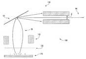
- FIG. 1Ais a side view of microbeam radiotherapy of a target within an object
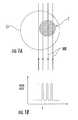
- FIG. 1Bis a graphical representation of the dose rate distribution across the x-ray microbeam of FIG. 1A ;
- FIG. 3is a schematic diagram of a field emission x-ray source for use with a microbeam radiotherapy system according to an embodiment of the presently disclosed subject matter
- FIG. 4is a schematic diagram of a field emission x-ray source for use with a microbeam radiotherapy system according to another embodiment of the presently disclosed subject matter;
- FIG. 5is a top plan view of a microbeam radiotherapy system according to an embodiment of the presently disclosed subject matter
- FIG. 6is a top plan view of a microbeam radiotherapy system arranged in a ring-shaped array according to an embodiment of the presently disclosed subject matter
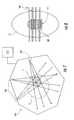
- FIG. 7is a top plan view of a microbeam radiotherapy system arranged in a polygonal array according to an embodiment of the presently disclosed subject matter
- FIG. 8is a side view of microbeam radiotherapy of a target within an object according to an embodiment of the presently disclosed subject matter.
- FIG. 9is a flow chart for a method for microbeam radiotherapy according to an embodiment of the presently disclosed subject matter.
- a traditional x-ray sourcegenerates x-ray radiation from a small area on the x-ray anode (“focal spot”) that receives electrons.
- the local temperature on the anodecan reach over 1500° C. when it is bombarded by the high energy electrons.
- the maximum x-ray dosecan be limited by the heat load that can be tolerated by the anode, which is also related to the size of the focal spot.
- LINACcan deliver a dose of only about 5 Gy/min.
- the present subject matterprovides compact, non-synchrotron source MRT devices, systems, and methods that can utilize multiple separated, narrow x-ray planar or line beams to deliver radiation at a comparatively higher dose rate.
- the MRT devices, systems, and methodscan be used, for example, for cancer treatment for humans including brain tumors and for intra-operative radiation therapy. It is also envisioned that MRT devices, systems, and methods as disclosed herein can be used for cancer research in animal models.
- the fan-beam angle ⁇(i.e., the spread of the fan-beam) can also be collimated such that the x-ray radiation covers primarily the region occupied by target T.
- the systemcan also comprise a radiochromic film (e.g., Gafchromic XR-QA) positioned between each x-ray source 100 and target T.
- x-ray microbeam MBcan be generated with significantly higher dose rate than what is used in clinical treatment.
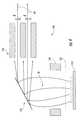
- the systemcan comprise a multi-slit microbeam collimator or a plurality of collimators 150 , shown in FIG. 4 , which can likewise be positioned in the path of the emitted x-ray beam. This arrangement can create a plurality of non-overlapping (e.g., parallel) x-ray microbeams MB emitted from each of x-ray sources 100 .
- a plurality of x-ray sources 100can be assembled in a distributed x-ray source array 200 as shown in FIG. 5 .
- Each x-ray source 100can be a distinct element, with an independent cathode 110 and anode 130 , which can be operated independently or in combination with other of the plurality of x-ray sources 100 .
- x-ray source array 200can comprise an anode ring and an opposing cathode ring inside a vacuum container.
- cathode ring and anode ringcan be operated collectively to produce x-ray radiation from the anode ring and irradiate target T within object O.
- x-ray source array 200functions as a distributed x-ray source. Instead of using one parallel x-ray beam delivering the radiation from one direction or two orthogonal beam arrays (i.e., as done in the experiments performed at the synchrotron sources), x-ray source array 200 surrounds target T to be irradiated. In this way, x-ray radiation can be delivered from multiple directions to a common focus to increase the amount of radiation received at target T without increasing the amount of radiation received at any intervening portion of object O outside of target T.
- each of the plurality of x-ray sources 100can be arranged such that x-ray microbeams MB from one of x-ray sources 100 irradiate a first portion of target T, x-ray microbeams MB from a second of x-ray sources 100 irradiate a second portion of target T different from the first portion, and so on.
- a first set of x-ray microbeams MBcan irradiate target T along a plurality of parallel radiation planes while a separate set of x-ray microbeams, designated MB′ in FIG.
- the x-ray radiation at target Thas a substantially continuous dose distribution even though each individual x-ray microbeam MB does not.
- X-ray source array 200can be configured to be in any of a variety of geometries, such as a ring, an arc, a polygon, or a linear array.
- x-ray source array 200can have a ring-shaped structure.
- Object Ocan be positioned inside the ring structure, with target T at a focus of the plurality of x-ray sources 100 , and a plurality of x-ray microbeams can thereby be emitted from multiple locations along a circumference of the ring towards target T.
- x-ray source array 200can have a polygonal structure with multiple segments, each segment essentially operating as a linear x-ray source array.
- x-ray source array 200distributes the power over a larger area and/or to multiple focal points on the x-ray anode so that a high dose rate can be achieved.
- a current state-of-art commercial thermionic x-ray tubecan be operated at around 100 kW at an effective focal spot size of 1 ⁇ 1 mm (after reflection). This is insufficient for the dose rate required for MRT.
- x-ray microbeams MBcan be generated around the circumference of a ring- or polygon-shaped anode structure and directed towards target T. By distributing the power over a large area, a much higher x-ray dose can be achieved without generating excessive heat loads at any one x-ray anode. Further, through the use of carbon-nanotube-based field emission x-ray sources 100 , the size of the x-ray focal spot can be reduced compared to prior art devices (i.e., less than 1 ⁇ 1 mm).
- a system for microbeam radiotherapycan comprise a controller 210 that can set the treatment parameters, including the dose to be delivered, the dwell time, the width of the x-ray radiation plane, and the spacing between adjacent radiation planes.
- the systemcan also comprise a patient bed for supporting the patient undergoing radiotherapy (i.e., object O) and a positioning device 220 that can align target T with the radiation field.
- the alignment of x-ray source array 200can be performed using an x-ray computed tomography (CT) scanner 222 (e.g., a dynamic micro-CT) in connection with positioning device 220 .
- CT scanner 222can identify the location of target T, as well as any peripheral structures of object O (e.g., normal tissue surrounding a tumor), and positioning device 220 can then be used to align target T with a focus of microbeams MB.
- a method for microbeam radiotherapycan comprise positioning distributed x-ray source array 200 about target T to be irradiated (e.g., a tumor within a medical patient), x-ray source array 200 comprising a plurality of carbon-nanotube field emission x-ray sources 100 , and simultaneously generating a plurality of x-ray microbeams MB from the plurality of carbon-nanotube field emission x-ray sources 100 .
- X-ray source array 200can be structured such that x-ray microbeams MB can be generated from the plurality of field emission x-ray sources 100 at different locations on x-ray source array 200 .
- X-ray sources 100can be switched to deliver x-ray microbeams MB to either one or several parallel radiation planes on target T in a short time.
- a treatment planning programcan be used to determine the radiation dose, the width of the x-ray beam, the spacing between the x-ray radiation planes, and the exposure time, each of which can be controlled by a controller 220 in communication with x-ray source array 200 .
- x-ray source array 200can be translated after each exposure to a sequence of positions within a small interval, and x-ray source array 200 can be operated to irradiate target T after each translation. The process can be repeated until the entire area of target T is irradiated. In this way, x-ray source array 200 can deliver x-ray radiation to target T with the dose being distributed in alternating high and low dose planes.
- a method for microbeam radiotherapycan comprise identifying a region of interest (ROI) for irradiation (e.g., target T), and aligning the ROI with a radiation field.
- aligning the ROIcan comprise positioning object O on a patient bed and aligning the region of interest of object O to be irradiated, such as a tumor (i.e., target T), with a focus of x-ray microbeams MB.
- a positioning device 220 discussed abovecan be used to align target T with the radiation field. This alignment can be facilitated by first locating target T within object O.
- this locatingcan be accomplished using an imaging device, such as an x-ray computed tomography scanner 222 . It can be further advantageous to monitor the location of target T during the course of treatment. For example, physiological motions of object O generally or target T specifically can be monitored, and the operation of x-ray source array 200 can be synchronized with such physiological motions, which can minimize blurring of the irradiation field due to the motions.
- the methodcan further comprise determining a dose, width, and spacing of the radiation plane generated by x-ray source array 200 , and irradiating the ROI. As discussed above, either object O or x-ray source array 200 can be translated by a predetermined distance, and the irradiation process can be repeated until the entire ROI is irradiated.
- microbeam radiotherapy systems and methodscan generate spatially discrete x-ray microbeams with planar and other geometries with high dose rate for microbeam therapy.
- Such microbeam radiotherapy systems and methodscan provide can be used for human cancer treatment such as human external beam treatment, intra-operative radiation therapy, brachytherapy, and for preclinical cancer research on animal cancer models.
Landscapes
- Health & Medical Sciences (AREA)
- Engineering & Computer Science (AREA)
- Biomedical Technology (AREA)
- Pathology (AREA)
- Nuclear Medicine, Radiotherapy & Molecular Imaging (AREA)
- Radiology & Medical Imaging (AREA)
- Life Sciences & Earth Sciences (AREA)
- Animal Behavior & Ethology (AREA)
- General Health & Medical Sciences (AREA)
- Public Health (AREA)
- Veterinary Medicine (AREA)
- Radiation-Therapy Devices (AREA)
Abstract
Description
Claims (15)
Priority Applications (2)
| Application Number | Priority Date | Filing Date | Title |
|---|---|---|---|
| US12/688,425US8600003B2 (en) | 2009-01-16 | 2010-01-15 | Compact microbeam radiation therapy systems and methods for cancer treatment and research |
| US14/090,863US8995608B2 (en) | 2009-01-16 | 2013-11-26 | Compact microbeam radiation therapy systems and methods for cancer treatment and research |
Applications Claiming Priority (2)
| Application Number | Priority Date | Filing Date | Title |
|---|---|---|---|
| US20524009P | 2009-01-16 | 2009-01-16 | |
| US12/688,425US8600003B2 (en) | 2009-01-16 | 2010-01-15 | Compact microbeam radiation therapy systems and methods for cancer treatment and research |
Related Child Applications (1)
| Application Number | Title | Priority Date | Filing Date |
|---|---|---|---|
| US14/090,863ContinuationUS8995608B2 (en) | 2009-01-16 | 2013-11-26 | Compact microbeam radiation therapy systems and methods for cancer treatment and research |
Publications (2)
| Publication Number | Publication Date |
|---|---|
| US20100329413A1 US20100329413A1 (en) | 2010-12-30 |
| US8600003B2true US8600003B2 (en) | 2013-12-03 |
Family
ID=43366658
Family Applications (2)
| Application Number | Title | Priority Date | Filing Date |
|---|---|---|---|
| US12/688,425Active2032-02-11US8600003B2 (en) | 2009-01-16 | 2010-01-15 | Compact microbeam radiation therapy systems and methods for cancer treatment and research |
| US14/090,863ActiveUS8995608B2 (en) | 2009-01-16 | 2013-11-26 | Compact microbeam radiation therapy systems and methods for cancer treatment and research |
Family Applications After (1)
| Application Number | Title | Priority Date | Filing Date |
|---|---|---|---|
| US14/090,863ActiveUS8995608B2 (en) | 2009-01-16 | 2013-11-26 | Compact microbeam radiation therapy systems and methods for cancer treatment and research |
Country Status (2)
| Country | Link |
|---|---|
| US (2) | US8600003B2 (en) |
| CN (1) | CN101927065B (en) |
Cited By (23)
| Publication number | Priority date | Publication date | Assignee | Title |
|---|---|---|---|---|
| US8995608B2 (en) | 2009-01-16 | 2015-03-31 | The University Of North Carolina At Chapel Hill | Compact microbeam radiation therapy systems and methods for cancer treatment and research |
| WO2020227719A1 (en)* | 2019-05-09 | 2020-11-12 | The Regents Of The University Of Michigan | Combined radiation acoustics and ultrasound for radiotherapy guidance and cancer targeting |
| US10918886B2 (en) | 2019-06-10 | 2021-02-16 | Varian Medical Systems, Inc. | Flash therapy treatment planning and oncology information system having dose rate prescription and dose rate mapping |
| US10960231B2 (en) | 2016-04-01 | 2021-03-30 | Varian Medical Systems, Inc. | Radiation therapy systems and methods |
| US11090508B2 (en) | 2019-03-08 | 2021-08-17 | Varian Medical Systems Particle Therapy Gmbh & Co. Kg | System and method for biological treatment planning and decision support |
| US11103727B2 (en) | 2019-03-08 | 2021-08-31 | Varian Medical Systems International Ag | Model based PBS optimization for flash therapy treatment planning and oncology information system |
| US11116995B2 (en) | 2019-03-06 | 2021-09-14 | Varian Medical Systems, Inc. | Radiation treatment planning based on dose rate |
| US11173325B2 (en)* | 2017-07-21 | 2021-11-16 | Varian Medical Systems, Inc. | Methods of use of ultra-high dose rate radiation and therapeutic agent |
| US11291859B2 (en) | 2019-10-03 | 2022-04-05 | Varian Medical Systems, Inc. | Radiation treatment planning for delivering high dose rates to spots in a target |
| US11348755B2 (en) | 2018-07-25 | 2022-05-31 | Varian Medical Systems, Inc. | Radiation anode target systems and methods |
| US11478664B2 (en) | 2017-07-21 | 2022-10-25 | Varian Medical Systems, Inc. | Particle beam gun control systems and methods |
| US11534625B2 (en) | 2019-03-06 | 2022-12-27 | Varian Medical Systems, Inc. | Radiation treatment based on dose rate |
| US11541252B2 (en) | 2020-06-23 | 2023-01-03 | Varian Medical Systems, Inc. | Defining dose rate for pencil beam scanning |
| US11590364B2 (en) | 2017-07-21 | 2023-02-28 | Varian Medical Systems International Ag | Material inserts for radiation therapy |
| US11673003B2 (en) | 2017-07-21 | 2023-06-13 | Varian Medical Systems, Inc. | Dose aspects of radiation therapy planning and treatment |
| US11712579B2 (en) | 2017-07-21 | 2023-08-01 | Varian Medical Systems, Inc. | Range compensators for radiation therapy |
| US11766574B2 (en) | 2017-07-21 | 2023-09-26 | Varian Medical Systems, Inc. | Geometric aspects of radiation therapy planning and treatment |
| US11857805B2 (en) | 2017-11-16 | 2024-01-02 | Varian Medical Systems, Inc. | Increased beam output and dynamic field shaping for radiotherapy system |
| US11865361B2 (en) | 2020-04-03 | 2024-01-09 | Varian Medical Systems, Inc. | System and method for scanning pattern optimization for flash therapy treatment planning |
| US11957934B2 (en) | 2020-07-01 | 2024-04-16 | Siemens Healthineers International Ag | Methods and systems using modeling of crystalline materials for spot placement for radiation therapy |
| US11986677B2 (en) | 2017-07-21 | 2024-05-21 | Siemens Healthineers International Ag | Triggered treatment systems and methods |
| US12064645B2 (en) | 2020-07-02 | 2024-08-20 | Siemens Healthineers International Ag | Methods and systems used for planning radiation treatment |
| US12390662B2 (en) | 2020-04-02 | 2025-08-19 | Siemens Healthineers International Ag | System and method for proton therapy treatment planning with proton energy and spot optimization |
Families Citing this family (34)
| Publication number | Priority date | Publication date | Assignee | Title |
|---|---|---|---|---|
| US8155262B2 (en) | 2005-04-25 | 2012-04-10 | The University Of North Carolina At Chapel Hill | Methods, systems, and computer program products for multiplexing computed tomography |
| US8189893B2 (en) | 2006-05-19 | 2012-05-29 | The University Of North Carolina At Chapel Hill | Methods, systems, and computer program products for binary multiplexing x-ray radiography |
| US8934605B2 (en) | 2010-02-24 | 2015-01-13 | Accuray Incorporated | Gantry image guided radiotherapy system and related treatment delivery methods |
| WO2011156526A2 (en) | 2010-06-08 | 2011-12-15 | Accuray, Inc. | Imaging methods and target tracking for image-guided radiation treatment |
| US9125570B2 (en)* | 2010-07-16 | 2015-09-08 | The Board Of Trustees Of The Leland Stanford Junior University | Real-time tomosynthesis guidance for radiation therapy |
| US8358739B2 (en) | 2010-09-03 | 2013-01-22 | The University Of North Carolina At Chapel Hill | Systems and methods for temporal multiplexing X-ray imaging |
| US8915833B1 (en)* | 2011-02-15 | 2014-12-23 | Velayudhan Sahadevan | Image guided intraoperative simultaneous several ports microbeam radiation therapy with microfocus X-ray tubes |
| US9555264B1 (en)* | 2011-02-15 | 2017-01-31 | Velayudhan Sahadevan | MEMS based parallel microbeam radiosurgery without adaptive resistance to radiation |
| US9415240B2 (en) | 2011-10-21 | 2016-08-16 | Accuray Incorporated | Apparatus for generating multi-energy x-ray images and methods of using the same |
| WO2013065762A1 (en)* | 2011-11-02 | 2013-05-10 | 富士フイルム株式会社 | Radiation emission device, radiation emission method, and program storage medium |
| US9227086B2 (en)* | 2012-06-08 | 2016-01-05 | Varian Medical Systems, Inc. | High energy microbeam radiosurgery |
| US9233260B2 (en)* | 2013-03-29 | 2016-01-12 | Microbeam Therapy, Llc. | Magnetic confinement for microbeam radiation damage area |
| SG11201509670VA (en) | 2013-06-04 | 2015-12-30 | Fumedica Ag | Cytotoxic substance for use in combination with radiotherapy in cancer treatment |
| WO2015038832A1 (en)* | 2013-09-11 | 2015-03-19 | The Board Of Trustees Of The Leland Stanford Junior University | Arrays of accelerating structures and rapid imaging for facilitating rapid radiation therapies |
| FR3013225B1 (en) | 2013-11-20 | 2018-09-14 | Pmb | IONIZING RADIATION IRRADIATION DEVICE, IN PARTICULAR FOR RADIOTHERAPY AND / OR RADIOBIOLOGY |
| CN104434165A (en)* | 2014-12-19 | 2015-03-25 | 深圳先进技术研究院 | X-ray imaging equipment |
| CN108348768B (en)* | 2015-11-17 | 2020-07-28 | 株式会社日立制作所 | Treatment planning devices and radiation therapy systems |
| EP3472850B1 (en)* | 2016-06-17 | 2021-03-24 | The Institute of Cancer Research: Royal Cancer Hospital | X-ray micro-beam production and high brilliance x-ray production |
| CN106409639B (en)* | 2016-12-15 | 2019-03-01 | 清华大学 | Film photocathode distribution X-ray generator and the CT equipment with the device |
| CN106783484B (en)* | 2016-12-15 | 2018-10-16 | 清华大学 | Photocathode distribution X-ray generator and CT equipment with the device |
| WO2018222839A1 (en) | 2017-06-01 | 2018-12-06 | Radiabeam Technologies, Llc | Split structure particle accelerators |
| WO2019099902A1 (en)* | 2017-11-17 | 2019-05-23 | The Research Foundation for State University of New York | A method for treating damaged peripheral nerves using x-ray microbeam irradiation |
| WO2019166702A1 (en)* | 2018-02-28 | 2019-09-06 | Hagalife | Use of a flash irradiation method to increase longevity and/or to delay the effects of ageing in mammals |
| WO2020018904A1 (en)* | 2018-07-19 | 2020-01-23 | Varian Medical Systems, Inc. | Methods of use of ultra-high dose rate radiation and therapeutic agents |
| CN111010868B (en) | 2018-08-08 | 2022-01-11 | 西安大医集团股份有限公司 | Method and device for correcting collimator of radiotherapy equipment |
| WO2020051915A1 (en)* | 2018-09-14 | 2020-03-19 | 西安大医集团有限公司 | Radiotherapy device and control method and apparatus thereof |
| WO2020061204A1 (en) | 2018-09-21 | 2020-03-26 | Radiabeam Technologies, Llc | Modified split structure particle accelerators |
| CN109846507A (en)* | 2019-02-18 | 2019-06-07 | 麦默真空技术无锡有限公司 | A kind of system for CT detection |
| WO2021113323A1 (en)* | 2019-12-06 | 2021-06-10 | Radiabeam Technologies, Llc | Linear accelerator for generating high x-ray doses |
| EP3933881A1 (en) | 2020-06-30 | 2022-01-05 | VEC Imaging GmbH & Co. KG | X-ray source with multiple grids |
| US11883687B2 (en) | 2020-09-08 | 2024-01-30 | Shanghai United Imaging Healthcare Co., Ltd. | X-ray imaging system for radiation therapy |
| US12230468B2 (en) | 2022-06-30 | 2025-02-18 | Varex Imaging Corporation | X-ray system with field emitters and arc protection |
| WO2025017482A1 (en)* | 2023-07-17 | 2025-01-23 | Ncx Corporation | System and method for x-ray imaging and targeted x-ray therapy |
| US12329988B1 (en)* | 2023-12-19 | 2025-06-17 | CureRays, Inc. | Apparatus and method for radiation therapy |
Citations (146)
| Publication number | Priority date | Publication date | Assignee | Title |
|---|---|---|---|---|
| GB679617A (en) | 1947-09-27 | 1952-09-24 | Westinghouse Electric Int Co | Improvements in or relating to x-ray apparatus |
| US2842706A (en) | 1956-03-01 | 1958-07-08 | Dobischek Dietrich | Cold cathode vacuum tube |
| US3617285A (en) | 1969-10-21 | 1971-11-02 | William Joseph Staudenmayer | Light intensifying screens |
| US3733484A (en) | 1969-10-29 | 1973-05-15 | Walter C Mc Crone Associates I | Control for electron microprobe |
| US3753020A (en) | 1971-11-26 | 1973-08-14 | Philips Electronics And Pharm | Multi-anode x-ray tube |
| US3783288A (en) | 1972-06-26 | 1974-01-01 | Field Emission Corp | Pulsed vacuum arc operation of field emission x-ray tube without anode melting |
| US3921022A (en) | 1974-09-03 | 1975-11-18 | Rca Corp | Field emitting device and method of making same |
| US3932756A (en) | 1974-06-24 | 1976-01-13 | Sybron Corporation | X-ray detector for a panoramic X-ray device |
| US4012656A (en) | 1974-12-09 | 1977-03-15 | Norman Ralph L | X-ray tube |
| US4145614A (en) | 1976-10-13 | 1979-03-20 | U.S. Philips Corporation | Device for producing two- and/or three-dimensional images of three dimensional objects |
| US4253221A (en) | 1979-06-14 | 1981-03-03 | Georgia Tech Research Institute | Method of producing low voltage field emission cathode structure |
| US4289969A (en) | 1978-07-10 | 1981-09-15 | Butler Greenwich Inc. | Radiation imaging apparatus |
| US4382184A (en) | 1978-11-24 | 1983-05-03 | Cardiac Imaging Limited Partnership | Apparatus and method for simultaneously displaying relative displacements of a fluctuating biological object |
| US4712226A (en) | 1985-09-13 | 1987-12-08 | Siemens Aktiengesellschaft | Stereoscopic x-ray tube |
| US4780612A (en) | 1987-01-30 | 1988-10-25 | Hughes Aircraft Company | Method and apparatus for multiplexing signals from electromagnetic radiation detectors |
| US4809308A (en) | 1986-02-20 | 1989-02-28 | Irt Corporation | Method and apparatus for performing automated circuit board solder quality inspections |
| US4926452A (en) | 1987-10-30 | 1990-05-15 | Four Pi Systems Corporation | Automated laminography system for inspection of electronics |
| US4958365A (en) | 1981-10-21 | 1990-09-18 | Elscint Ltd. | Medical imaging device using triggered plasma cathode flash X-ray source |
| US5129850A (en) | 1991-08-20 | 1992-07-14 | Motorola, Inc. | Method of making a molded field emission electron emitter employing a diamond coating |
| US5138237A (en) | 1991-08-20 | 1992-08-11 | Motorola, Inc. | Field emission electron device employing a modulatable diamond semiconductor emitter |
| US5245648A (en) | 1991-04-05 | 1993-09-14 | The United States Of America As Represented By The United States Department Of Energy | X-ray tomographic image magnification process, system and apparatus therefor |
| US5305363A (en) | 1992-01-06 | 1994-04-19 | Picker International, Inc. | Computerized tomographic scanner having a toroidal x-ray tube with a stationary annular anode and a rotating cathode assembly |
| EP0268488B1 (en) | 1986-11-19 | 1994-05-25 | Exxon Research And Engineering Company | Method and apparatus for utilizing an electro-optic detector in a microtomography system |
| US5371778A (en) | 1991-11-29 | 1994-12-06 | Picker International, Inc. | Concurrent display and adjustment of 3D projection, coronal slice, sagittal slice, and transverse slice images |
| US5377249A (en) | 1991-11-28 | 1994-12-27 | Siemens Aktiengesellschaft | Computer tomography apparatus having a partial ring x-ray source and a partial ring detector |
| US5390112A (en) | 1993-10-04 | 1995-02-14 | General Electric Company | Three-dimensional computerized tomography scanning method and system for imaging large objects with smaller area detectors |
| US5412703A (en) | 1993-02-04 | 1995-05-02 | Institute For Radiological Image Science, Inc. | Reduced partial volume artifacts in image reconstruction, with application to X-ray computed tomography |
| US5424054A (en) | 1993-05-21 | 1995-06-13 | International Business Machines Corporation | Carbon fibers and method for their production |
| US5557105A (en) | 1991-06-10 | 1996-09-17 | Fujitsu Limited | Pattern inspection apparatus and electron beam apparatus |
| US5578821A (en) | 1992-05-27 | 1996-11-26 | Kla Instruments Corporation | Electron beam inspection system and method |
| US5594770A (en) | 1994-11-18 | 1997-01-14 | Thermospectra Corporation | Method and apparatus for imaging obscured areas of a test object |
| US5616368A (en) | 1995-01-31 | 1997-04-01 | Lucent Technologies Inc. | Field emission devices employing activated diamond particle emitters and methods for making same |
| US5623180A (en) | 1994-10-31 | 1997-04-22 | Lucent Technologies Inc. | Electron field emitters comprising particles cooled with low voltage emitting material |
| US5637950A (en) | 1994-10-31 | 1997-06-10 | Lucent Technologies Inc. | Field emission devices employing enhanced diamond field emitters |
| US5648699A (en) | 1995-11-09 | 1997-07-15 | Lucent Technologies Inc. | Field emission devices employing improved emitters on metal foil and methods for making such devices |
| US5692028A (en) | 1995-09-07 | 1997-11-25 | Heimann Systems Gmbh | X-ray examining apparatus for large-volume goods |
| US5726524A (en) | 1996-05-31 | 1998-03-10 | Minnesota Mining And Manufacturing Company | Field emission device having nanostructured emitters |
| US5754437A (en) | 1996-09-10 | 1998-05-19 | Tektronix, Inc. | Phase measurement apparatus and method |
| US5764683A (en) | 1996-02-12 | 1998-06-09 | American Science And Engineering, Inc. | Mobile X-ray inspection system for large objects |
| US5773834A (en) | 1996-02-13 | 1998-06-30 | Director-General Of Agency Of Industrial Science And Technology | Method of forming carbon nanotubes on a carbonaceous body, composite material obtained thereby and electron beam source element using same |
| US5773921A (en) | 1994-02-23 | 1998-06-30 | Keesmann; Till | Field emission cathode having an electrically conducting material shaped of a narrow rod or knife edge |
| US5834783A (en) | 1996-03-04 | 1998-11-10 | Canon Kabushiki Kaisha | Electron beam exposure apparatus and method, and device manufacturing method |
| US5844963A (en) | 1997-08-28 | 1998-12-01 | Varian Associates, Inc. | Electron beam superimposition method and apparatus |
| EP0648468B1 (en) | 1993-10-19 | 1999-03-17 | Picker International, Inc. | Computed tomographic imaging |
| US5910974A (en) | 1995-03-20 | 1999-06-08 | Siemens Aktiengesellschaft | Method for operating an x-ray tube |
| CN2336381Y (en) | 1997-10-24 | 1999-09-01 | 西北核技术研究所 | Portable pulse digital X-ray imaging apparatus |
| DE19700992C2 (en) | 1997-01-14 | 1999-10-07 | Siemens Ag | X-ray tube |
| US5973444A (en) | 1995-12-20 | 1999-10-26 | Advanced Technology Materials, Inc. | Carbon fiber-based field emission devices |
| US5976444A (en) | 1996-09-24 | 1999-11-02 | The United States Of America As Represented By The Secretary Of The Navy | Nanochannel glass replica membranes |
| USRE36415E (en) | 1994-02-08 | 1999-11-30 | Analogic Corporation | X-ray tomography system with gantry pivot and translation control |
| US6019656A (en) | 1997-11-29 | 2000-02-01 | Electronics And Telecommunications Research Institute | Method of fabricating a field emission device by using carbon nano-tubes |
| US6028911A (en) | 1998-08-03 | 2000-02-22 | Rigaku Industrial Corporation | X-ray analyzing apparatus with enhanced radiation intensity |
| US6057637A (en) | 1996-09-13 | 2000-05-02 | The Regents Of The University Of California | Field emission electron source |
| US6087765A (en) | 1997-12-03 | 2000-07-11 | Motorola, Inc. | Electron emissive film |
| JP2000208028A (en) | 1999-01-12 | 2000-07-28 | Matsushita Electric Ind Co Ltd | Electron emitting device and method of manufacturing the same |
| US6097788A (en) | 1998-04-14 | 2000-08-01 | Siemens Aktiengesellschaft | Method and apparatus for multi-planar radiation emission for imaging |
| US6097138A (en) | 1996-09-18 | 2000-08-01 | Kabushiki Kaisha Toshiba | Field emission cold-cathode device |
| US6125167A (en) | 1998-11-25 | 2000-09-26 | Picker International, Inc. | Rotating anode x-ray tube with multiple simultaneously emitting focal spots |
| EP1050272A1 (en) | 1999-05-07 | 2000-11-08 | General Electric Company | Volumetric computed tomography system for cardiac imaging |
| WO2000051936A3 (en) | 1999-03-01 | 2001-01-04 | Univ North Carolina Chapel Hill | Nanotube-based high energy material and method |
| US6178226B1 (en) | 1997-08-18 | 2001-01-23 | Siemens Aktiengesellschaft | Method for controlling the electron current in an x-ray tube, and x-ray system operating according to the method |
| US6192104B1 (en) | 1998-11-30 | 2001-02-20 | American Science And Engineering, Inc. | Fan and pencil beams from a common source for x-ray inspection |
| US6250984B1 (en) | 1999-01-25 | 2001-06-26 | Agere Systems Guardian Corp. | Article comprising enhanced nanotube emitter structure and process for fabricating article |
| US6259765B1 (en) | 1997-06-13 | 2001-07-10 | Commissariat A L'energie Atomique | X-ray tube comprising an electron source with microtips and magnetic guiding means |
| JP2001190550A (en) | 2000-01-12 | 2001-07-17 | Univ Nihon | X-ray CT imaging method and apparatus |
| US6271923B1 (en) | 1999-05-05 | 2001-08-07 | Zygo Corporation | Interferometry system having a dynamic beam steering assembly for measuring angle and distance |
| US6277318B1 (en) | 1999-08-18 | 2001-08-21 | Agere Systems Guardian Corp. | Method for fabrication of patterned carbon nanotube films |
| US20010019601A1 (en) | 2000-03-06 | 2001-09-06 | Rigaku Corporation | X-ray generator |
| US6297592B1 (en) | 2000-08-04 | 2001-10-02 | Lucent Technologies Inc. | Microwave vacuum tube device employing grid-modulated cold cathode source having nanotube emitters |
| US6333968B1 (en) | 2000-05-05 | 2001-12-25 | The United States Of America As Represented By The Secretary Of The Navy | Transmission cathode for X-ray production |
| US6334939B1 (en) | 2000-06-15 | 2002-01-01 | The University Of North Carolina At Chapel Hill | Nanostructure-based high energy capacity material |
| US6350628B1 (en) | 1999-11-22 | 2002-02-26 | National Science Council | Method of fabricating a field emission device on the sidewalls of holes formed in an insulator layer |
| US6376973B1 (en) | 1997-04-02 | 2002-04-23 | E. I. Du Pont De Nemours And Company | Metal-oxygen-carbon field emitters |
| US6385292B1 (en) | 2000-12-29 | 2002-05-07 | Ge Medical Systems Global Technology Company, Llc | Solid-state CT system and method |
| US20020085674A1 (en) | 2000-12-29 | 2002-07-04 | Price John Scott | Radiography device with flat panel X-ray source |
| US20020094064A1 (en) | 2000-10-06 | 2002-07-18 | Zhou Otto Z. | Large-area individually addressable multi-beam x-ray system and method of forming same |
| US20020110996A1 (en) | 2000-12-08 | 2002-08-15 | Si Diamond Technology, Inc. | Low work function material |
| US6440761B1 (en) | 1999-05-24 | 2002-08-27 | Samsung Sdi Co., Ltd. | Carbon nanotube field emission array and method for fabricating the same |
| US6445122B1 (en) | 2000-02-22 | 2002-09-03 | Industrial Technology Research Institute | Field emission display panel having cathode and anode on the same panel substrate |
| US6459767B1 (en) | 2000-12-12 | 2002-10-01 | Oxford Instruments, Inc. | Portable x-ray fluorescence spectrometer |
| US20020140336A1 (en) | 2001-03-27 | 2002-10-03 | Stoner Brian R. | Coated electrode with enhanced electron emission and ignition characteristics |
| US6470068B2 (en) | 2001-01-19 | 2002-10-22 | Cheng Chin-An | X-ray computer tomography scanning system |
| US20020159565A1 (en) | 2001-04-30 | 2002-10-31 | Serge Muller | Method and device for sampling tissue during a radiological examination |
| US20020171357A1 (en) | 2001-03-27 | 2002-11-21 | Xiao-Dong Sun | Electron emitter including carbon nanotubes and its application in gas discharge devices |
| US20020193040A1 (en) | 2001-06-18 | 2002-12-19 | Zhou Otto Z. | Method of making nanotube-based material with enhanced electron field emission properties |
| US20020191751A1 (en) | 2001-01-23 | 2002-12-19 | Bogatu Ioan Niculae | Filter assembly for X-ray filter system for medical imaging contrast enhancement |
| US6498349B1 (en) | 1997-02-05 | 2002-12-24 | Ut-Battelle | Electrostatically focused addressable field emission array chips (AFEA's) for high-speed massively parallel maskless digital E-beam direct write lithography and scanning electron microscopy |
| US20030002628A1 (en) | 2001-06-27 | 2003-01-02 | Wilson Colin R. | Method and system for generating an electron beam in x-ray generating devices |
| US20030002627A1 (en) | 2000-09-28 | 2003-01-02 | Oxford Instruments, Inc. | Cold emitter x-ray tube incorporating a nanostructured carbon film electron emitter |
| US6510195B1 (en) | 2001-07-18 | 2003-01-21 | Koninklijke Philips Electronics, N.V. | Solid state x-radiation detector modules and mosaics thereof, and an imaging method and apparatus employing the same |
| WO2003012816A2 (en) | 2001-07-30 | 2003-02-13 | Moxtek, Inc. | Mobile miniature x-ray source |
| US6529575B1 (en) | 2002-04-29 | 2003-03-04 | Ge Medical Systems Global Technology Company, Llc | Adaptive projection filtering scheme for noise reduction |
| US20030048868A1 (en) | 2001-08-09 | 2003-03-13 | Bailey Eric M. | Combined radiation therapy and imaging system and method |
| US6545396B1 (en) | 1999-10-21 | 2003-04-08 | Sharp Kabushiki Kaisha | Image forming device using field emission electron source arrays |
| US6553096B1 (en) | 2000-10-06 | 2003-04-22 | The University Of North Carolina Chapel Hill | X-ray generating mechanism using electron field emission cathode |
| US6560309B1 (en) | 1999-11-28 | 2003-05-06 | Siemens Aktiengesellschaft | Method for examining a body region executing a periodic motion |
| US20030102222A1 (en) | 2001-11-30 | 2003-06-05 | Zhou Otto Z. | Deposition method for nanostructure materials |
| US20030103666A1 (en) | 2001-12-05 | 2003-06-05 | General Electric Company One Research Circle | Iterative X-ray scatter correction method and apparatus |
| US6621887B2 (en) | 2001-10-15 | 2003-09-16 | General Electric Company | Method and apparatus for processing a fluoroscopic image |
| US6630772B1 (en) | 1998-09-21 | 2003-10-07 | Agere Systems Inc. | Device comprising carbon nanotube field emitter structure and process for forming device |
| US20030198318A1 (en) | 2002-04-17 | 2003-10-23 | Ge Medical Systems Global Technology Company, Llc | X-ray source and method having cathode with curved emission surface |
| US6674837B1 (en) | 2001-06-15 | 2004-01-06 | Nan Crystal Imaging Corporation | X-ray imaging system incorporating pixelated X-ray source and synchronized detector |
| US6672926B2 (en) | 2001-06-01 | 2004-01-06 | Delta Optoelectronics, Inc. | Method of fabricating emitter of field emission display |
| US20040017888A1 (en) | 2002-07-24 | 2004-01-29 | Seppi Edward J. | Radiation scanning of objects for contraband |
| US20040065465A1 (en) | 2002-10-03 | 2004-04-08 | Koninklijke Philips Electronics N.V. | Symmetrical multiple-slice computed tomography data management system |
| US20040108298A1 (en) | 2002-07-03 | 2004-06-10 | Applied Nanotechnologies, Inc. | Fabrication and activation processes for nanostructure composite field emission cathodes |
| US20040114721A1 (en) | 2000-10-06 | 2004-06-17 | Applied Nanotechnologies, Inc. | Devices and methods for producing multiple x-ray beams from multiple locations |
| US6754300B2 (en) | 2002-06-20 | 2004-06-22 | Ge Medical Systems Global Technology Company, Llc | Methods and apparatus for operating a radiation source |
| USRE38561E1 (en) | 1995-02-22 | 2004-08-03 | Till Keesmann | Field emission cathode |
| US20040213378A1 (en) | 2003-04-24 | 2004-10-28 | The University Of North Carolina At Chapel Hill | Computed tomography system for imaging of human and small animal |
| US20040240616A1 (en) | 2003-05-30 | 2004-12-02 | Applied Nanotechnologies, Inc. | Devices and methods for producing multiple X-ray beams from multiple locations |
| US20040256975A1 (en) | 2003-06-19 | 2004-12-23 | Applied Nanotechnologies, Inc. | Electrode and associated devices and methods |
| US6852973B2 (en) | 2002-04-10 | 2005-02-08 | Sii Nanotechnology Inc. | Scanning charged particle microscope |
| US20050028554A1 (en) | 2000-05-31 | 2005-02-10 | Alfred Wanner | Multistoreyed bath condenser |
| US20050084073A1 (en) | 2003-10-15 | 2005-04-21 | Seppi Edward J. | Multi-energy x-ray source |
| US20050117701A1 (en) | 2003-12-01 | 2005-06-02 | Nelson James M. | Backscatter imaging using hadamard transform masking |
| US20050175151A1 (en) | 2004-02-05 | 2005-08-11 | Ge Medical Systems Global Technology Company, Llc | Emitter array configurations for a stationary ct system |
| US6950493B2 (en) | 2003-06-25 | 2005-09-27 | Besson Guy M | Dynamic multi-spectral CT imaging |
| US20050222323A1 (en) | 2002-04-11 | 2005-10-06 | Xiao-Qi Zhou | Thermally conductive coating compositions, methods of production and uses thereof |
| US20050226371A1 (en) | 2004-04-06 | 2005-10-13 | General Electric Company | Stationary Tomographic Mammography System |
| US20050269559A1 (en) | 2004-06-02 | 2005-12-08 | Xintek, Inc. | Field emission ion source based on nanostructure-containing material |
| US7027558B2 (en) | 2001-10-26 | 2006-04-11 | Siemens Medical Solutions Usa, Inc. | X-ray therapy electronic portal imaging system and method for artifact reduction |
| US7046757B1 (en) | 2005-04-18 | 2006-05-16 | Siemens Medical Solutions Usa, Inc. | X-ray scatter elimination by frequency shifting |
| US7082182B2 (en) | 2000-10-06 | 2006-07-25 | The University Of North Carolina At Chapel Hill | Computed tomography system for imaging of human and small animal |
| US7085351B2 (en) | 2000-10-06 | 2006-08-01 | University Of North Carolina At Chapel Hill | Method and apparatus for controlling electron beam current |
| US7147894B2 (en) | 2002-03-25 | 2006-12-12 | The University Of North Carolina At Chapel Hill | Method for assembling nano objects |
| US20060291711A1 (en) | 2003-07-03 | 2006-12-28 | Ge Medical Systems Global Technology Company, Inc. | Imaging chain for digital tomosynthesis on a flat panel detector |
| US7220971B1 (en) | 2004-12-29 | 2007-05-22 | The University Of North Carolina At Chapel Hill | Multi-pixel electron microbeam irradiator systems and methods for selectively irradiating predetermined locations |
| US7227924B2 (en) | 2000-10-06 | 2007-06-05 | The University Of North Carolina At Chapel Hill | Computed tomography scanning system and method using a field emission x-ray source |
| US7245692B2 (en) | 2005-04-25 | 2007-07-17 | The University Of North Carolina At Chapel Hill | X-ray imaging systems and methods using temporal digital signal processing for reducing noise and for obtaining multiple images simultaneously |
| US7305064B2 (en)* | 2005-02-10 | 2007-12-04 | Brookhaven Science Associates, Llc | Methods for assisting recovery of damaged brain and spinal cord using arrays of X-Ray microplanar beams |
| US20080031400A1 (en) | 2004-05-06 | 2008-02-07 | Luc Beaulieu | 3D Localization Of Objects From Tomography Data |
| US20080069420A1 (en) | 2006-05-19 | 2008-03-20 | Jian Zhang | Methods, systems, and computer porgram products for binary multiplexing x-ray radiography |
| US20080144772A1 (en)* | 2006-12-14 | 2008-06-19 | Byong Yong Yi | Treatment-Speed Regulated Tumor-Tracking |
| US7486772B2 (en) | 2005-11-17 | 2009-02-03 | Xintek, Inc. | Systems and methods for x-ray imaging and scanning of objects |
| US20090093863A1 (en)* | 2007-10-04 | 2009-04-09 | Brookhaven Science Associates, Llc | Method and Devices for Performing Stereotactic Microbeam Radiation Therapy |
| US7567647B1 (en)* | 2008-04-11 | 2009-07-28 | Siemens Medical Solutions Usa, Inc. | Source array translation for digital tomosynthesis |
| US20090196393A1 (en)* | 2008-02-01 | 2009-08-06 | Ge Wang | Interior Tomography and Instant Tomography by Reconstruction from Truncated Limited-Angle Projection Data |
| US7684537B2 (en) | 2007-04-23 | 2010-03-23 | Ge Medical Systems Global Technology Company, Llc | X-ray CT apparatus |
| US7741624B1 (en) | 2008-05-03 | 2010-06-22 | Velayudhan Sahadevan | Single session interactive ultra-short duration super-high biological dose rate radiation therapy and radiosurgery |
| US7751528B2 (en) | 2007-07-19 | 2010-07-06 | The University Of North Carolina | Stationary x-ray digital breast tomosynthesis systems and related methods |
| US20100239064A1 (en) | 2005-04-25 | 2010-09-23 | Unc-Chapel Hill | Methods, systems, and computer program products for multiplexing computed tomography |
| US7835492B1 (en) | 2007-11-27 | 2010-11-16 | Velayudhan Sahadevan | Lethal and sublethal damage repair inhibiting image guided simultaneous all field divergent and pencil beam photon and electron radiation therapy and radiosurgery |
| US20100329413A1 (en) | 2009-01-16 | 2010-12-30 | Zhou Otto Z | Compact microbeam radiation therapy systems and methods for cancer treatment and research |
| US7902530B1 (en) | 2006-04-06 | 2011-03-08 | Velayudhan Sahadevan | Multiple medical accelerators and a kV-CT incorporated radiation therapy device and semi-automated custom reshapeable blocks for all field synchronous image guided 3-D-conformal-intensity modulated radiation therapy |
| US8358739B2 (en) | 2010-09-03 | 2013-01-22 | The University Of North Carolina At Chapel Hill | Systems and methods for temporal multiplexing X-ray imaging |
Family Cites Families (17)
| Publication number | Priority date | Publication date | Assignee | Title |
|---|---|---|---|---|
| JPS53103392A (en) | 1977-02-21 | 1978-09-08 | Shimadzu Corp | Tomograph |
| JPH08264139A (en) | 1995-03-22 | 1996-10-11 | Hamamatsu Photonics Kk | X-ray generating apparatus |
| JP3439590B2 (en) | 1995-12-22 | 2003-08-25 | 株式会社荏原製作所 | X-ray source |
| JP3792859B2 (en) | 1997-10-03 | 2006-07-05 | 株式会社ノリタケカンパニーリミテド | Electron gun |
| JP3828270B2 (en) | 1998-03-05 | 2006-10-04 | 株式会社ノリタケカンパニーリミテド | Electron emission device |
| FI981431L (en)* | 1998-06-22 | 1999-12-23 | Nokia Mobile Phones Ltd | Measurement method |
| US6421416B1 (en)* | 2000-02-11 | 2002-07-16 | Photoelectron Corporation | Apparatus for local radiation therapy |
| JP2001250496A (en) | 2000-03-06 | 2001-09-14 | Rigaku Corp | X-ray generator |
| CN1316279A (en)* | 2000-05-08 | 2001-10-10 | 董森 | X-ray magnetic therapy machine for PDT therapy of cancer by combining radiatherapy with chemicotherapy and its medicine |
| GB0015928D0 (en) | 2000-06-30 | 2000-08-23 | Printable Field Emitters Limit | Field emitters |
| CN1316279C (en) | 2000-08-11 | 2007-05-16 | 株式会社索佳 | Automatic focus mechanism on measuring device |
| CN2440535Y (en)* | 2000-09-26 | 2001-08-01 | 官爱平 | Composite focusing device for X ray-microwave knife |
| JP2006513410A (en) | 2003-01-06 | 2006-04-20 | コーニンクレッカ フィリップス エレクトロニクス エヌ ヴィ | Single photon tomography with constant radius |
| GB0309379D0 (en) | 2003-04-25 | 2003-06-04 | Cxr Ltd | X-ray scanning |
| GB0309383D0 (en) | 2003-04-25 | 2003-06-04 | Cxr Ltd | X-ray tube electron sources |
| US8262555B2 (en)* | 2003-06-18 | 2012-09-11 | Xoft, Inc. | Method for adaptive radiation treatment of breast tissue surrounding a cancer resection cavity of arbitrary shape |
| CN101041989A (en) | 2004-08-05 | 2007-09-26 | 邱则有 | Reinforced bar concrete solid load-carrying structural storied building cover |
- 2010
- 2010-01-15USUS12/688,425patent/US8600003B2/enactiveActive
- 2010-01-18CNCN201010142047.3Apatent/CN101927065B/ennot_activeExpired - Fee Related
- 2013
- 2013-11-26USUS14/090,863patent/US8995608B2/enactiveActive
Patent Citations (169)
| Publication number | Priority date | Publication date | Assignee | Title |
|---|---|---|---|---|
| GB679617A (en) | 1947-09-27 | 1952-09-24 | Westinghouse Electric Int Co | Improvements in or relating to x-ray apparatus |
| US2842706A (en) | 1956-03-01 | 1958-07-08 | Dobischek Dietrich | Cold cathode vacuum tube |
| US3617285A (en) | 1969-10-21 | 1971-11-02 | William Joseph Staudenmayer | Light intensifying screens |
| US3733484A (en) | 1969-10-29 | 1973-05-15 | Walter C Mc Crone Associates I | Control for electron microprobe |
| US3753020A (en) | 1971-11-26 | 1973-08-14 | Philips Electronics And Pharm | Multi-anode x-ray tube |
| US3783288A (en) | 1972-06-26 | 1974-01-01 | Field Emission Corp | Pulsed vacuum arc operation of field emission x-ray tube without anode melting |
| US3932756A (en) | 1974-06-24 | 1976-01-13 | Sybron Corporation | X-ray detector for a panoramic X-ray device |
| US3921022A (en) | 1974-09-03 | 1975-11-18 | Rca Corp | Field emitting device and method of making same |
| US4012656A (en) | 1974-12-09 | 1977-03-15 | Norman Ralph L | X-ray tube |
| US4145614A (en) | 1976-10-13 | 1979-03-20 | U.S. Philips Corporation | Device for producing two- and/or three-dimensional images of three dimensional objects |
| US4289969A (en) | 1978-07-10 | 1981-09-15 | Butler Greenwich Inc. | Radiation imaging apparatus |
| US4382184A (en) | 1978-11-24 | 1983-05-03 | Cardiac Imaging Limited Partnership | Apparatus and method for simultaneously displaying relative displacements of a fluctuating biological object |
| US4253221A (en) | 1979-06-14 | 1981-03-03 | Georgia Tech Research Institute | Method of producing low voltage field emission cathode structure |
| US4958365A (en) | 1981-10-21 | 1990-09-18 | Elscint Ltd. | Medical imaging device using triggered plasma cathode flash X-ray source |
| US4712226A (en) | 1985-09-13 | 1987-12-08 | Siemens Aktiengesellschaft | Stereoscopic x-ray tube |
| US4809308A (en) | 1986-02-20 | 1989-02-28 | Irt Corporation | Method and apparatus for performing automated circuit board solder quality inspections |
| EP0268488B1 (en) | 1986-11-19 | 1994-05-25 | Exxon Research And Engineering Company | Method and apparatus for utilizing an electro-optic detector in a microtomography system |
| US4780612A (en) | 1987-01-30 | 1988-10-25 | Hughes Aircraft Company | Method and apparatus for multiplexing signals from electromagnetic radiation detectors |
| US4926452A (en) | 1987-10-30 | 1990-05-15 | Four Pi Systems Corporation | Automated laminography system for inspection of electronics |
| US5245648A (en) | 1991-04-05 | 1993-09-14 | The United States Of America As Represented By The United States Department Of Energy | X-ray tomographic image magnification process, system and apparatus therefor |
| US5557105A (en) | 1991-06-10 | 1996-09-17 | Fujitsu Limited | Pattern inspection apparatus and electron beam apparatus |
| US5129850A (en) | 1991-08-20 | 1992-07-14 | Motorola, Inc. | Method of making a molded field emission electron emitter employing a diamond coating |
| US5138237A (en) | 1991-08-20 | 1992-08-11 | Motorola, Inc. | Field emission electron device employing a modulatable diamond semiconductor emitter |
| US5377249A (en) | 1991-11-28 | 1994-12-27 | Siemens Aktiengesellschaft | Computer tomography apparatus having a partial ring x-ray source and a partial ring detector |
| US5371778A (en) | 1991-11-29 | 1994-12-06 | Picker International, Inc. | Concurrent display and adjustment of 3D projection, coronal slice, sagittal slice, and transverse slice images |
| US5305363A (en) | 1992-01-06 | 1994-04-19 | Picker International, Inc. | Computerized tomographic scanner having a toroidal x-ray tube with a stationary annular anode and a rotating cathode assembly |
| US5578821A (en) | 1992-05-27 | 1996-11-26 | Kla Instruments Corporation | Electron beam inspection system and method |
| US5412703A (en) | 1993-02-04 | 1995-05-02 | Institute For Radiological Image Science, Inc. | Reduced partial volume artifacts in image reconstruction, with application to X-ray computed tomography |
| US5424054A (en) | 1993-05-21 | 1995-06-13 | International Business Machines Corporation | Carbon fibers and method for their production |
| US5390112A (en) | 1993-10-04 | 1995-02-14 | General Electric Company | Three-dimensional computerized tomography scanning method and system for imaging large objects with smaller area detectors |
| EP0648468B1 (en) | 1993-10-19 | 1999-03-17 | Picker International, Inc. | Computed tomographic imaging |
| USRE36415E (en) | 1994-02-08 | 1999-11-30 | Analogic Corporation | X-ray tomography system with gantry pivot and translation control |
| US5773921A (en) | 1994-02-23 | 1998-06-30 | Keesmann; Till | Field emission cathode having an electrically conducting material shaped of a narrow rod or knife edge |
| USRE38223E1 (en) | 1994-02-23 | 2003-08-19 | Till Keesmann | Field emission cathode having an electrically conducting material shaped of a narrow rod or knife edge |
| US20040036402A1 (en) | 1994-02-23 | 2004-02-26 | Till Keesmann | Field emission cathode using carbon fibers |
| US5623180A (en) | 1994-10-31 | 1997-04-22 | Lucent Technologies Inc. | Electron field emitters comprising particles cooled with low voltage emitting material |
| US5637950A (en) | 1994-10-31 | 1997-06-10 | Lucent Technologies Inc. | Field emission devices employing enhanced diamond field emitters |
| US5594770A (en) | 1994-11-18 | 1997-01-14 | Thermospectra Corporation | Method and apparatus for imaging obscured areas of a test object |
| US5616368A (en) | 1995-01-31 | 1997-04-01 | Lucent Technologies Inc. | Field emission devices employing activated diamond particle emitters and methods for making same |
| USRE38561E1 (en) | 1995-02-22 | 2004-08-03 | Till Keesmann | Field emission cathode |
| US5910974A (en) | 1995-03-20 | 1999-06-08 | Siemens Aktiengesellschaft | Method for operating an x-ray tube |
| US5692028A (en) | 1995-09-07 | 1997-11-25 | Heimann Systems Gmbh | X-ray examining apparatus for large-volume goods |
| US5648699A (en) | 1995-11-09 | 1997-07-15 | Lucent Technologies Inc. | Field emission devices employing improved emitters on metal foil and methods for making such devices |
| US5973444A (en) | 1995-12-20 | 1999-10-26 | Advanced Technology Materials, Inc. | Carbon fiber-based field emission devices |
| US5764683A (en) | 1996-02-12 | 1998-06-09 | American Science And Engineering, Inc. | Mobile X-ray inspection system for large objects |
| US5764683B1 (en) | 1996-02-12 | 2000-11-21 | American Science & Eng Inc | Mobile x-ray inspection system for large objects |
| US5773834A (en) | 1996-02-13 | 1998-06-30 | Director-General Of Agency Of Industrial Science And Technology | Method of forming carbon nanotubes on a carbonaceous body, composite material obtained thereby and electron beam source element using same |
| US5834783A (en) | 1996-03-04 | 1998-11-10 | Canon Kabushiki Kaisha | Electron beam exposure apparatus and method, and device manufacturing method |
| US5726524A (en) | 1996-05-31 | 1998-03-10 | Minnesota Mining And Manufacturing Company | Field emission device having nanostructured emitters |
| US5754437A (en) | 1996-09-10 | 1998-05-19 | Tektronix, Inc. | Phase measurement apparatus and method |
| US6057637A (en) | 1996-09-13 | 2000-05-02 | The Regents Of The University Of California | Field emission electron source |
| US6097138A (en) | 1996-09-18 | 2000-08-01 | Kabushiki Kaisha Toshiba | Field emission cold-cathode device |
| US5976444A (en) | 1996-09-24 | 1999-11-02 | The United States Of America As Represented By The Secretary Of The Navy | Nanochannel glass replica membranes |
| DE19700992C2 (en) | 1997-01-14 | 1999-10-07 | Siemens Ag | X-ray tube |
| US6498349B1 (en) | 1997-02-05 | 2002-12-24 | Ut-Battelle | Electrostatically focused addressable field emission array chips (AFEA's) for high-speed massively parallel maskless digital E-beam direct write lithography and scanning electron microscopy |
| US6376973B1 (en) | 1997-04-02 | 2002-04-23 | E. I. Du Pont De Nemours And Company | Metal-oxygen-carbon field emitters |
| US6259765B1 (en) | 1997-06-13 | 2001-07-10 | Commissariat A L'energie Atomique | X-ray tube comprising an electron source with microtips and magnetic guiding means |
| US6178226B1 (en) | 1997-08-18 | 2001-01-23 | Siemens Aktiengesellschaft | Method for controlling the electron current in an x-ray tube, and x-ray system operating according to the method |
| US5844963A (en) | 1997-08-28 | 1998-12-01 | Varian Associates, Inc. | Electron beam superimposition method and apparatus |
| CN2336381Y (en) | 1997-10-24 | 1999-09-01 | 西北核技术研究所 | Portable pulse digital X-ray imaging apparatus |
| US6019656A (en) | 1997-11-29 | 2000-02-01 | Electronics And Telecommunications Research Institute | Method of fabricating a field emission device by using carbon nano-tubes |
| US6087765A (en) | 1997-12-03 | 2000-07-11 | Motorola, Inc. | Electron emissive film |
| US6097788A (en) | 1998-04-14 | 2000-08-01 | Siemens Aktiengesellschaft | Method and apparatus for multi-planar radiation emission for imaging |
| US6028911A (en) | 1998-08-03 | 2000-02-22 | Rigaku Industrial Corporation | X-ray analyzing apparatus with enhanced radiation intensity |
| US6630772B1 (en) | 1998-09-21 | 2003-10-07 | Agere Systems Inc. | Device comprising carbon nanotube field emitter structure and process for forming device |
| US6125167A (en) | 1998-11-25 | 2000-09-26 | Picker International, Inc. | Rotating anode x-ray tube with multiple simultaneously emitting focal spots |
| US6192104B1 (en) | 1998-11-30 | 2001-02-20 | American Science And Engineering, Inc. | Fan and pencil beams from a common source for x-ray inspection |
| JP2000208028A (en) | 1999-01-12 | 2000-07-28 | Matsushita Electric Ind Co Ltd | Electron emitting device and method of manufacturing the same |
| US6250984B1 (en) | 1999-01-25 | 2001-06-26 | Agere Systems Guardian Corp. | Article comprising enhanced nanotube emitter structure and process for fabricating article |
| US6280697B1 (en) | 1999-03-01 | 2001-08-28 | The University Of North Carolina-Chapel Hill | Nanotube-based high energy material and method |
| WO2000051936A3 (en) | 1999-03-01 | 2001-01-04 | Univ North Carolina Chapel Hill | Nanotube-based high energy material and method |
| US6271923B1 (en) | 1999-05-05 | 2001-08-07 | Zygo Corporation | Interferometry system having a dynamic beam steering assembly for measuring angle and distance |
| EP1050272A1 (en) | 1999-05-07 | 2000-11-08 | General Electric Company | Volumetric computed tomography system for cardiac imaging |
| US6440761B1 (en) | 1999-05-24 | 2002-08-27 | Samsung Sdi Co., Ltd. | Carbon nanotube field emission array and method for fabricating the same |
| US6277318B1 (en) | 1999-08-18 | 2001-08-21 | Agere Systems Guardian Corp. | Method for fabrication of patterned carbon nanotube films |
| US6545396B1 (en) | 1999-10-21 | 2003-04-08 | Sharp Kabushiki Kaisha | Image forming device using field emission electron source arrays |
| US6350628B1 (en) | 1999-11-22 | 2002-02-26 | National Science Council | Method of fabricating a field emission device on the sidewalls of holes formed in an insulator layer |
| US6560309B1 (en) | 1999-11-28 | 2003-05-06 | Siemens Aktiengesellschaft | Method for examining a body region executing a periodic motion |
| JP2001190550A (en) | 2000-01-12 | 2001-07-17 | Univ Nihon | X-ray CT imaging method and apparatus |
| US6445122B1 (en) | 2000-02-22 | 2002-09-03 | Industrial Technology Research Institute | Field emission display panel having cathode and anode on the same panel substrate |
| US6456691B2 (en) | 2000-03-06 | 2002-09-24 | Rigaku Corporation | X-ray generator |
| US20010019601A1 (en) | 2000-03-06 | 2001-09-06 | Rigaku Corporation | X-ray generator |
| US6333968B1 (en) | 2000-05-05 | 2001-12-25 | The United States Of America As Represented By The Secretary Of The Navy | Transmission cathode for X-ray production |
| US20050028554A1 (en) | 2000-05-31 | 2005-02-10 | Alfred Wanner | Multistoreyed bath condenser |
| US6334939B1 (en) | 2000-06-15 | 2002-01-01 | The University Of North Carolina At Chapel Hill | Nanostructure-based high energy capacity material |
| US6297592B1 (en) | 2000-08-04 | 2001-10-02 | Lucent Technologies Inc. | Microwave vacuum tube device employing grid-modulated cold cathode source having nanotube emitters |
| US20030002627A1 (en) | 2000-09-28 | 2003-01-02 | Oxford Instruments, Inc. | Cold emitter x-ray tube incorporating a nanostructured carbon film electron emitter |
| US6876724B2 (en) | 2000-10-06 | 2005-04-05 | The University Of North Carolina - Chapel Hill | Large-area individually addressable multi-beam x-ray system and method of forming same |
| US7359484B2 (en) | 2000-10-06 | 2008-04-15 | Xintek, Inc | Devices and methods for producing multiple x-ray beams from multiple locations |
| US7082182B2 (en) | 2000-10-06 | 2006-07-25 | The University Of North Carolina At Chapel Hill | Computed tomography system for imaging of human and small animal |
| US20060018432A1 (en) | 2000-10-06 | 2006-01-26 | The University Of North Carolina At Chapel Hill | Large-area individually addressable multi-beam x-ray system and method of forming same |
| US6980627B2 (en) | 2000-10-06 | 2005-12-27 | Xintek, Inc. | Devices and methods for producing multiple x-ray beams from multiple locations |
| US20070009081A1 (en) | 2000-10-06 | 2007-01-11 | The University Of North Carolina At Chapel Hill | Computed tomography system for imaging of human and small animal |
| US7227924B2 (en) | 2000-10-06 | 2007-06-05 | The University Of North Carolina At Chapel Hill | Computed tomography scanning system and method using a field emission x-ray source |
| US20030142790A1 (en) | 2000-10-06 | 2003-07-31 | Zhou Otto Z. | X-ray generating mechanism using electron field emission cathode |
| US7085351B2 (en) | 2000-10-06 | 2006-08-01 | University Of North Carolina At Chapel Hill | Method and apparatus for controlling electron beam current |
| US6850595B2 (en) | 2000-10-06 | 2005-02-01 | The University Of North Carolina At Chapel Hill | X-ray generating mechanism using electron field emission cathode |
| US20020094064A1 (en) | 2000-10-06 | 2002-07-18 | Zhou Otto Z. | Large-area individually addressable multi-beam x-ray system and method of forming same |
| US20040114721A1 (en) | 2000-10-06 | 2004-06-17 | Applied Nanotechnologies, Inc. | Devices and methods for producing multiple x-ray beams from multiple locations |
| US6553096B1 (en) | 2000-10-06 | 2003-04-22 | The University Of North Carolina Chapel Hill | X-ray generating mechanism using electron field emission cathode |
| US20020110996A1 (en) | 2000-12-08 | 2002-08-15 | Si Diamond Technology, Inc. | Low work function material |
| US6459767B1 (en) | 2000-12-12 | 2002-10-01 | Oxford Instruments, Inc. | Portable x-ray fluorescence spectrometer |
| US6385292B1 (en) | 2000-12-29 | 2002-05-07 | Ge Medical Systems Global Technology Company, Llc | Solid-state CT system and method |
| US20020085674A1 (en) | 2000-12-29 | 2002-07-04 | Price John Scott | Radiography device with flat panel X-ray source |
| DE10164315A1 (en) | 2000-12-29 | 2002-08-08 | Ge Med Sys Global Tech Co Llc | Radiography facility with flat panel x-ray source |
| DE10164318A1 (en) | 2000-12-29 | 2002-08-08 | Ge Med Sys Global Tech Co Llc | Solid-state CT system and method |
| US6470068B2 (en) | 2001-01-19 | 2002-10-22 | Cheng Chin-An | X-ray computer tomography scanning system |
| US6650730B2 (en) | 2001-01-23 | 2003-11-18 | Fartech, Inc. | Filter assembly for X-ray filter system for medical imaging contrast enhancement |
| US20020191751A1 (en) | 2001-01-23 | 2002-12-19 | Bogatu Ioan Niculae | Filter assembly for X-ray filter system for medical imaging contrast enhancement |
| US20020171357A1 (en) | 2001-03-27 | 2002-11-21 | Xiao-Dong Sun | Electron emitter including carbon nanotubes and its application in gas discharge devices |
| US6965199B2 (en) | 2001-03-27 | 2005-11-15 | The University Of North Carolina At Chapel Hill | Coated electrode with enhanced electron emission and ignition characteristics |
| US20020140336A1 (en) | 2001-03-27 | 2002-10-03 | Stoner Brian R. | Coated electrode with enhanced electron emission and ignition characteristics |
| US20020159565A1 (en) | 2001-04-30 | 2002-10-31 | Serge Muller | Method and device for sampling tissue during a radiological examination |
| US6672926B2 (en) | 2001-06-01 | 2004-01-06 | Delta Optoelectronics, Inc. | Method of fabricating emitter of field emission display |
| US6674837B1 (en) | 2001-06-15 | 2004-01-06 | Nan Crystal Imaging Corporation | X-ray imaging system incorporating pixelated X-ray source and synchronized detector |
| US20020193040A1 (en) | 2001-06-18 | 2002-12-19 | Zhou Otto Z. | Method of making nanotube-based material with enhanced electron field emission properties |
| US6787122B2 (en) | 2001-06-18 | 2004-09-07 | The University Of North Carolina At Chapel Hill | Method of making nanotube-based material with enhanced electron field emission properties |
| JP2003100242A (en) | 2001-06-27 | 2003-04-04 | Ge Medical Systems Global Technology Co Llc | Method and system for generating electron beam in x-ray generating device |
| US20030002628A1 (en) | 2001-06-27 | 2003-01-02 | Wilson Colin R. | Method and system for generating an electron beam in x-ray generating devices |
| US6510195B1 (en) | 2001-07-18 | 2003-01-21 | Koninklijke Philips Electronics, N.V. | Solid state x-radiation detector modules and mosaics thereof, and an imaging method and apparatus employing the same |
| WO2003012816A2 (en) | 2001-07-30 | 2003-02-13 | Moxtek, Inc. | Mobile miniature x-ray source |
| US20030048868A1 (en) | 2001-08-09 | 2003-03-13 | Bailey Eric M. | Combined radiation therapy and imaging system and method |
| US6621887B2 (en) | 2001-10-15 | 2003-09-16 | General Electric Company | Method and apparatus for processing a fluoroscopic image |
| US7027558B2 (en) | 2001-10-26 | 2006-04-11 | Siemens Medical Solutions Usa, Inc. | X-ray therapy electronic portal imaging system and method for artifact reduction |
| US20030102222A1 (en) | 2001-11-30 | 2003-06-05 | Zhou Otto Z. | Deposition method for nanostructure materials |
| US20050133372A1 (en) | 2001-11-30 | 2005-06-23 | The University Of North Carolina | Method and apparatus for attaching nanostructure-containing material onto a sharp tip of an object and related articles |
| US20030103666A1 (en) | 2001-12-05 | 2003-06-05 | General Electric Company One Research Circle | Iterative X-ray scatter correction method and apparatus |
| US7147894B2 (en) | 2002-03-25 | 2006-12-12 | The University Of North Carolina At Chapel Hill | Method for assembling nano objects |
| US6852973B2 (en) | 2002-04-10 | 2005-02-08 | Sii Nanotechnology Inc. | Scanning charged particle microscope |
| US20050222323A1 (en) | 2002-04-11 | 2005-10-06 | Xiao-Qi Zhou | Thermally conductive coating compositions, methods of production and uses thereof |
| US6760407B2 (en) | 2002-04-17 | 2004-07-06 | Ge Medical Global Technology Company, Llc | X-ray source and method having cathode with curved emission surface |
| US20030198318A1 (en) | 2002-04-17 | 2003-10-23 | Ge Medical Systems Global Technology Company, Llc | X-ray source and method having cathode with curved emission surface |
| US6529575B1 (en) | 2002-04-29 | 2003-03-04 | Ge Medical Systems Global Technology Company, Llc | Adaptive projection filtering scheme for noise reduction |
| US6754300B2 (en) | 2002-06-20 | 2004-06-22 | Ge Medical Systems Global Technology Company, Llc | Methods and apparatus for operating a radiation source |
| US20040108298A1 (en) | 2002-07-03 | 2004-06-10 | Applied Nanotechnologies, Inc. | Fabrication and activation processes for nanostructure composite field emission cathodes |
| US20040017888A1 (en) | 2002-07-24 | 2004-01-29 | Seppi Edward J. | Radiation scanning of objects for contraband |
| US20040065465A1 (en) | 2002-10-03 | 2004-04-08 | Koninklijke Philips Electronics N.V. | Symmetrical multiple-slice computed tomography data management system |
| US20040213378A1 (en) | 2003-04-24 | 2004-10-28 | The University Of North Carolina At Chapel Hill | Computed tomography system for imaging of human and small animal |
| US20040240616A1 (en) | 2003-05-30 | 2004-12-02 | Applied Nanotechnologies, Inc. | Devices and methods for producing multiple X-ray beams from multiple locations |
| US20040256975A1 (en) | 2003-06-19 | 2004-12-23 | Applied Nanotechnologies, Inc. | Electrode and associated devices and methods |
| US6950493B2 (en) | 2003-06-25 | 2005-09-27 | Besson Guy M | Dynamic multi-spectral CT imaging |
| US20060291711A1 (en) | 2003-07-03 | 2006-12-28 | Ge Medical Systems Global Technology Company, Inc. | Imaging chain for digital tomosynthesis on a flat panel detector |
| US20050084073A1 (en) | 2003-10-15 | 2005-04-21 | Seppi Edward J. | Multi-energy x-ray source |
| US20050117701A1 (en) | 2003-12-01 | 2005-06-02 | Nelson James M. | Backscatter imaging using hadamard transform masking |
| US20050175151A1 (en) | 2004-02-05 | 2005-08-11 | Ge Medical Systems Global Technology Company, Llc | Emitter array configurations for a stationary ct system |
| US20050226371A1 (en) | 2004-04-06 | 2005-10-13 | General Electric Company | Stationary Tomographic Mammography System |
| US20080031400A1 (en) | 2004-05-06 | 2008-02-07 | Luc Beaulieu | 3D Localization Of Objects From Tomography Data |
| US20050269559A1 (en) | 2004-06-02 | 2005-12-08 | Xintek, Inc. | Field emission ion source based on nanostructure-containing material |
| US7220971B1 (en) | 2004-12-29 | 2007-05-22 | The University Of North Carolina At Chapel Hill | Multi-pixel electron microbeam irradiator systems and methods for selectively irradiating predetermined locations |
| US7305064B2 (en)* | 2005-02-10 | 2007-12-04 | Brookhaven Science Associates, Llc | Methods for assisting recovery of damaged brain and spinal cord using arrays of X-Ray microplanar beams |
| US7046757B1 (en) | 2005-04-18 | 2006-05-16 | Siemens Medical Solutions Usa, Inc. | X-ray scatter elimination by frequency shifting |
| US7245692B2 (en) | 2005-04-25 | 2007-07-17 | The University Of North Carolina At Chapel Hill | X-ray imaging systems and methods using temporal digital signal processing for reducing noise and for obtaining multiple images simultaneously |
| US8155262B2 (en) | 2005-04-25 | 2012-04-10 | The University Of North Carolina At Chapel Hill | Methods, systems, and computer program products for multiplexing computed tomography |
| US20100239064A1 (en) | 2005-04-25 | 2010-09-23 | Unc-Chapel Hill | Methods, systems, and computer program products for multiplexing computed tomography |
| US7486772B2 (en) | 2005-11-17 | 2009-02-03 | Xintek, Inc. | Systems and methods for x-ray imaging and scanning of objects |
| US7902530B1 (en) | 2006-04-06 | 2011-03-08 | Velayudhan Sahadevan | Multiple medical accelerators and a kV-CT incorporated radiation therapy device and semi-automated custom reshapeable blocks for all field synchronous image guided 3-D-conformal-intensity modulated radiation therapy |
| US20080069420A1 (en) | 2006-05-19 | 2008-03-20 | Jian Zhang | Methods, systems, and computer porgram products for binary multiplexing x-ray radiography |
| US8189893B2 (en) | 2006-05-19 | 2012-05-29 | The University Of North Carolina At Chapel Hill | Methods, systems, and computer program products for binary multiplexing x-ray radiography |
| US20080144772A1 (en)* | 2006-12-14 | 2008-06-19 | Byong Yong Yi | Treatment-Speed Regulated Tumor-Tracking |
| US7684537B2 (en) | 2007-04-23 | 2010-03-23 | Ge Medical Systems Global Technology Company, Llc | X-ray CT apparatus |
| US7751528B2 (en) | 2007-07-19 | 2010-07-06 | The University Of North Carolina | Stationary x-ray digital breast tomosynthesis systems and related methods |
| US7643610B2 (en)* | 2007-10-04 | 2010-01-05 | Brookhaven Science Associates, Llc | Method and devices for performing stereotactic microbeam radiation therapy |
| US20090093863A1 (en)* | 2007-10-04 | 2009-04-09 | Brookhaven Science Associates, Llc | Method and Devices for Performing Stereotactic Microbeam Radiation Therapy |
| US7835492B1 (en) | 2007-11-27 | 2010-11-16 | Velayudhan Sahadevan | Lethal and sublethal damage repair inhibiting image guided simultaneous all field divergent and pencil beam photon and electron radiation therapy and radiosurgery |
| US20090196393A1 (en)* | 2008-02-01 | 2009-08-06 | Ge Wang | Interior Tomography and Instant Tomography by Reconstruction from Truncated Limited-Angle Projection Data |
| US7567647B1 (en)* | 2008-04-11 | 2009-07-28 | Siemens Medical Solutions Usa, Inc. | Source array translation for digital tomosynthesis |
| US7741624B1 (en) | 2008-05-03 | 2010-06-22 | Velayudhan Sahadevan | Single session interactive ultra-short duration super-high biological dose rate radiation therapy and radiosurgery |
| US20100329413A1 (en) | 2009-01-16 | 2010-12-30 | Zhou Otto Z | Compact microbeam radiation therapy systems and methods for cancer treatment and research |
| US8358739B2 (en) | 2010-09-03 | 2013-01-22 | The University Of North Carolina At Chapel Hill | Systems and methods for temporal multiplexing X-ray imaging |
Non-Patent Citations (140)
| Title |
|---|
| Bentley, M.D. et al., "The Use of Microcomputed Tomography to Study Microvasculature in Small Rodents", Am. J Physiol Regulatory Integrative Comp Physiol, 282, pp. R1267-R1279, 2002. |
| Bonard et al., "Field emission from single-wall carbon nanotube films", Appl. Phys. Left., vol. 73, No. 7, pp. 918-920 (Aug. 17, 1998). |
| Bower et al., "Synthesis and structure of pristine and alkali-metal-intercalated single-walled carbon nanotubes", Appl. Phys., A 67, pp. 47-52 (1998). |
| Bower, C. et al., "Fabrication and Field Emission Properties of Carbon Nanotube Cathodes", Mat. Res. Soc. Symp. Proc., vol. 593, pp. 215-220, 2000. |
| Brock et al., "Hadamard Transform Time-of-Flight Mass Spectrometry," Analytical Chemistry, vol. 70, No. 18, Sep. 15, 1998. |
| Brodie et al., "Vacuum Microelectronics", Advance in Electronics and Electron Physics, edited by P.W. Hawkes, vol. 83, pp. 1-106 (1992). |
| Bushong, S.C., "Radiologic Science for Technologist," Physics, Biology, and Protection, 6th Edition, Mosby, Inc., 1997 (excerpt relating to focusing and thermionic emission). |
| Cassell et al., "Large Scale CVD Synthesis of Single-Walled Carbon Nanotubes", J. Phys. Chem., B 103, pp. 6484-6492 (Jul. 20, 1999). |
| Charbonnier et al., "Resolution of Field-Emmision X-Ray Sources," Radiology, vol. 117: pp. 165-172 (Oct. 1975). |
| Cheng et al., "Dynamic radiography using a carbon-nanotube-based field emmision x-ray source," Review of Scientific Instruments, vol. 75, No. 10: pp. 3264-3267 (Oct. 2004). |
| Cheng et al., "Electron Field Emission from Carbon Nanotubes," C.R. Physique, pp. 1021-1033 (2003). |
| Chinese Notice of Grant for Application No. 200680043786.9 dated Nov. 5, 2012. |
| Chinese Office Action for Application No. 200710003710.X dated Feb. 5, 2013. |
| Chinese Office Action for Application No. 200880107680.X dated Jan. 14, 2013. |
| Confirmation of issuance of Chinese Patent No. ZL01820211.X corresponding to PCT/US01/30027 dated Feb. 4, 2009. |
| Confirmation that Chinese Application 093102622 issued on Mar. 1, 2009 as Patent No. TW I307110. |
| Corrected Notice of Allowance for U.S. Appl. No. 10/309,126 dated Sep. 14, 2004. |
| de Heer et al., "A Carbon Nanotube Field-Emission Electron Source", Science, vol. 270, pp. 1179-1180 (Nov. 17, 1995). |
| Decision on Rejection issued from the Chinese Patent Office dated Dec. 11, 2009 for Chinese Application No. 200710003710.X. |
| Dobbins III et al., "Digital x-ray tomosynthesis: current state of the art and clinical potential," Phys. Med. Biol. 48 (2003) R65-R106. |
| European Patent Office Examination Report dated Jun. 28, 2007 for European Patent Application No. 03702044.3. |
| European Search Report for EP 06815214 dated Oct. 25, 2011. |
| Examination Report from European Patent Office dated Mar. 3, 2008 for European Patent Application No. 03702044.3. |
| Feldkamp L.A. et al., "Practical Cone-Beam Algorithm", J. Opt. Soc. Am., 1(a):612-619, 1984. |
| Final Office Action for U.S. Appl. No. 09/679,303 dated May 6, 2002. |
| Final Office Action for U.S. Appl. No. 11/441,281 dated Sep. 30, 2010. |
| Final Office Action for U.S. Appl. No. 11/526,217 dated Aug. 19, 2011. |
| Final Office Action for U.S. Appl. No. 11/526,217 dated May 6, 2011. |
| Final Office Action for U.S. Appl. No. 11/804,897 dated Jul. 14, 2011. |
| First Office Action corresponding to Chinese Patent Application No. 200680043786.9 dated Jul. 6, 2010. |
| First Office Action for CN Appl. No. 200880107680.X dated Apr. 7, 2011. |
| First Office Action from Chinese Patent Office dated Mar. 6, 2009 for Chinese Patent Application No. 200480017120.7. |
| First Office Action from Chinese Patent Office for Chinese Patent Application No. 200710003710.X dated Apr. 24, 2009. |
| First Office Action from Chinese Patent Office for Chinese Patent Application Serial No. 200680013859.X dated Sep. 25, 2009. |
| First Office Action from Japanese Patent Office dated Jan. 6, 2009 for JP Application No. 2006-513282. |
| First Office Action from Japanese Patent Office for Japanese Patent Application No. 2002-535152, based on PCT/US01/30027 dated Oct. 17, 2008. |
| Gao et al., "Fabrication and Electron Field Emmision Properties of Carbon Nanotube Films by Electrophoretic Deposition," Advanced Materials, vol. 13, No. 23 (2001). |
| Geis et al., "Diamond emitters fabrication and theory", J. Vac. Sci. Technol. B, vol. 14, No. 3, pp. 2060-2067, May/Jun. 1996. |
| Hallenbeck, "Clinical Evaluation of the 350-kV Chest Radiography System," Radiology, vol. 117: pp. 1-4 (1974). |
| Hu, J. et al., "Chemistry and Physics in One Dimension: Synthesis and Properties of Nanowires and Nanotubes", Accounts of Chemical Research, vol. 32, pp. 435-445, 1999. |
| International Preliminary Report on Patentability for PCT/US04/12660 dated May 9, 2007. |
| International Search Report and Written Opinion for Application No. PCT/US05/03991 dated Jun. 22, 2006 / Aug. 14, 2006. |
| International Search Report and Written Opinion for PCT Application No. PCT/US08/70477 dated Oct. 1, 2008. |
| International Search Report and Written Opinion for PCT/US04/12660 dated Apr. 7, 2005. |
| International Search Report for Application No. PCT/US03/00537 dated Apr. 10, 2003. |
| International Search Report for corresponding International Application No. PCT/US05/47066 dated Oct. 6, 2006. |
| International Search Report for PCT/US06/37046 dated May 21, 2007. |
| Japanese Final Office Action for Japanese Patent Application No. 2003-562962 based on PCT/US03/00537 dated Mar. 30, 2009. |
| Japanese Office Action for JP Appl. No. 2008-532428 dated Sep. 20, 2011. |
| Japanese Patent Office Action for JP No. 2003-562962 for corresponding PCT No. US03/00537 dated Jun. 20, 2008. |
| Jerri, "The Shannon Sampling Theorem-Its Various Extensions and Applications: A Tutorial Review," IEEE, vol. 65, No. 11, pp. 1565-1596 (1977). |
| Journet et al., "Large-scale production of single-walled carbon nanotubes by the electric-arc technique", Nature, vol. 388, pp. 756-760 (Aug. 21, 1997). |
| Korean Intellectual Property Office (KIPO) Office Action for Korean Patent Application No. 10-2003-700004987 dated Jul. 19, 2007. |
| Korean Intellectual Property Office (KIPO) Office Action for Korean Patent Application No. 10-2004-7011373 dated Jun. 11, 2007. |
| Korean Office Action for Korean Patent Application No. 10-2004-7011373 dated Dec. 18, 2007. |
| Kruger et al., "Tomosynthesis Applied to Digital Subtraction Angiography," Radiology, V152, pp. 805-808 (1984). |
| Kumar et al., "Diamond-based field emission flat panel displays", Solid State Technology, vol. 38, pp. 71-74 (May 1995). |
| Lalush, "Feasibility of Transmission Micro-CT with Two Fan-Beam Sources," Proceedings of 26th Annual Int'l Conf on IEEE EMBS, pp. 1283-1286, Sep. 5, 2004. |
| Lee et al., "Novel Micro-CT Based on a Carbon Nanotube Field Emission X-ray Source," 2003 Radiological Society of North American Meeting, Abstract Code A21-182, Nov. 30, 2003. |
| Lee et al., "Pulsed X-Ray Imaging of Small Animals Using a Carbon Nanotube Based X-Ray Source" presented at the Academy of Molecular Imaging Annual Meeting, Orlando, FL, Molecular Imaging and Biology, vol. 6, No. 2, Abstract No. 41, p. 80 (Mar. 2004). |
| Moore et al., "Three-Dimensional X-Ray Laminography as a Tool for Detection and Characterization of BGA Package Defects", IEEE Transactions on Components and Packaging Technologies. vol. 25, No. 2, Jun. 2002. |
| Non-final Office Action for U.S. Appl. No. 09/679,303 dated Aug. 20, 2002. |
| Non-final Office Action for U.S. Appl. No. 09/679,303 dated Jan. 16, 2002. |
| Non-final Office Action for U.S. Appl. No. 10/051,183 dated Apr. 21, 2004. |
| Non-final Office Action for U.S. Appl. No. 10/051,183 dated Sep. 10, 2003. |
| Non-final Office Action for U.S. Appl. No. 10/309,126 dated Apr. 20, 2004. |
| Non-final Office Action for U.S. Appl. No. 10/309,126 dated May 22, 2003. |
| Non-final Office Action for U.S. Appl. No. 10/309,126 dated Nov. 5, 2003. |
| Non-final Office Action for U.S. Appl. No. 10/358,160 dated Sep. 21, 2004. |
| Non-final Office Action for U.S. Appl. No. 10/970,384 dated Apr. 8, 2008. |
| Non-Final Office Action for U.S. Appl. No. 11/320,515 dated Aug. 17, 2006. |
| Non-final Office Action for U.S. Appl. No. 11/415,953 dated Dec. 11, 2007. |
| Non-final Office Action for U.S. Appl. No. 11/441,281 dated Jan. 11, 2010. |
| Non-Final Office Action for U.S. Appl. No. 11/441,281 dated Mar. 15, 2011. |
| Non-Final Office Action for U.S. Appl. No. 11/441,281 dated Oct. 19, 2011. |
| Non-Final Office Action for U.S. Appl. No. 11/526,217 dated Oct. 13, 2010. |
| Non-Final Office Action for U.S. Appl. No. 11/804,897 dated Nov. 8, 2010. |
| Non-Final Office Action for U.S. Appl. No. 12/176,056 dated Sep. 2, 2009. |
| Non-final Office Action U.S. Appl. No. 10/358,160 dated Jun. 7, 2005. |
| Notice of Allowance dated for U.S. Appl. No. 11/051,332 dated Dec. 28, 2006. |
| Notice of Allowance for U.S. Appl. No. 09/679,303 dated Nov. 1, 2002. |
| Notice of Allowance for U.S. Appl. No. 10/051,183 dated Aug. 31, 2004. |
| Notice of Allowance for U.S. Appl. No. 10/309,126 dated Aug. 26, 2004. |
| Notice of Allowance for U.S. Appl. No. 11/526,217 dated Dec. 14, 2011. |
| Notice of Allowance for U.S. Appl. No. 11/804,897 dated Jan. 6, 2012. |
| Notice of Allowance for U.S. Appl. No. 11/875,260 dated Jan. 6, 2012. |
| Notice of Allowance U.S. Appl. No. 10/358,160 dated Feb. 8, 2006. |
| Notice of Publication for Chinese Patent Application No. 200810215733.1 (Publication No. 101352353) dated Jan. 28, 2009. |
| Notification to Grant for Chinese Patent Application No. 200480017120.7 dated Jul. 12, 2011. |
| Notification to Grant for Chinese Patent Application No. 200810215733.1 dated Jun. 2, 2011. |
| Nyquist, "Certain Topics in Telegraphic Transmission Theory," IEEE, vol. 2, No. 2, pp. 208-305 (2002). |
| Office Action from Canadian Patent Office dated May 27, 2008 for Canadian Application No. 2,424,826. |
| Office Action from Japanese Patent Office for Japanese Patent Application No. 2003-580561 for corresponding PCT No. US03/06345 dated Sep. 3, 2008. |
| Office Action-Final for U.S. Appl. No. 11/441,281 dated Jun. 4, 2009. |
| Office Action-Restriction requirement for U.S. Appl. No. 11/051,332 dated Sep. 7, 2006. |
| Office Action-Restriction requirement for U.S. Appl. No. 11/415,953 dated May 22, 2008. |
| Office Action-Restriction requirement U.S. Appl. No. 10/358,160 dated Oct. 26, 2005. |
| Office Communication for U.S. Appl. No. 09/679,303 dated Feb. 6, 2003. |
| Office Communication for U.S. Appl. No. 10/051,183 dated Jan. 14, 2005. |
| Okano et al., "Electron emission from nitrogen-doped pyramidal-shape diamond and its battery operation", Appl. Phys. Lett., vol. 70, No. 16, pp. 2201-2203 (Apr. 21, 1997). |
| Okano et al., "Fabrication of a diamond field emitter array", Appl. Phys. Lett., vol. 64, No. 20, pp. 2742-2744 (May 16, 1994). |
| Okazaki et al., "A New Emission Spectrum of Au2 in the Gas Evaporation Technique: 761-809 nm", Jpn. J. Appl. Phys., vol. 37, Pt. 1, No. 1, pp. 349-350 (Jan. 1998). |
| Reexamination Notice for CN Appl No. 200710003710.X dated Sep. 21, 2011. |
| Resat et al., "Microbeam developments and applications: A low linear energy transfer perspective," Cancer and Metastasis Reviews 23: p. 323-331 (2004). |
| Ribbing et al., "Diamond membrane based sructures for miniature X-ray sources," Diamond and Related Materials, vol. 11: pp. 1-7 (2002). |
| Rinzler et al., "Unraveling Nanotubes: Field Emission from an Atomic Wire", Science, vol. 269, pp. 1550-1553 (Sep. 15, 1995). |
| Saito, Y. et al., "Cathode Ray Tube Lighting Elements with Carbon Nanotube Field Emitters", Jpn. J. Appl. Phys., vol. 37, pp. L346-L348, Part 2, No. 3B, Mar. 15, 1998. |
| Saito, Y. et al., "Field Emission Patterns from Single-Walled Carbon Nanotubes", Jpn. J. Appl. Phys., vol. 36, pp. L1340-L1342, Part 2, No. 10A, Oct. 1, 1997. |
| Second Chinese Office Action for Patent Application No. 03806739.0 dated Oct. 19, 2007. |
| Second Office Action corresponding to Chinese Patent Application No. 200680013859 dated Apr. 30, 2010. |
| Second Office Action for CN Appl. No. 2004-80017120.7 dated Nov. 17, 2010. |
| Second Office Action for CN Appl. No. 2006-80043786.9 dated Mar. 2, 2011. |
| Second Office Action from Japanese Patent Office dated Dec. 7, 2009 for Japanese Patent Application No. 2002-535152. |
| Second Reexamination Notice for CN Appl No. 200710003710.X dated Mar. 2012. |
| Shannon, "Communication in the Presence of Noise," IEEE, vol. 86, No. 2, pp. 447-108 (1998). |
| Sloane, "Multiplexing Methods in Spectroscopy," Mathematics Magazine, vol. 52, No. 2 (Mar. 1979), 71-80. |
| Sugie et al., "Carbon nanotubes as electron source in an x-ray tube," Applied Physics Letters, vol. 78, No. 17: pp. 2578-2580 (2001). |
| Supplementary European Search report dated Oct. 7, 2009 for EPO Application No. 04 77 5902 (PCT/U82004012660). |
| Supplementary European Search Report for European Patent Application No. 01981327.8 dated Jun. 22, 2009. |
| Taiwanese Office Action for Taiwan Patent No. 093102622 dated Dec. 21, 2007. |
| Tang, X. P. et al., "Electronic Structures of Single-Walled Carbon Nanotubes Determined by NMR", Science, vol. 288, pp. 492-494 (Apr. 21, 2000). |
| Thess, A. et al., "Crystalline Ropes of Metallic Carbon Nanotubes", Science, vol. 273, pp. 483-487 (Jul. 26, 1996). |
| Third Chinese Office Action dated Mar. 14, 2008 for Chinese Patent Application No. 01820211.X (PCT/US01/30027). |
| Third Office Action for CN Appl. No. 2006-80043786.9 dated Feb. 2, 2012. |
| Third Office Action for CN Appl. No. 2008-10215733.1 dated Dec. 14, 2010. |
| Third-Party Submission against U.S. Appl. No. 12/688,425 dated Feb. 28, 2011. |
| Traedo, "A Thousand Points of Light: The Hadamard Transform in Chemical Analysis and Instrumentation," Analytical Chemistry. vol. 61, No. 11, Jun. 1, 1989. |
| U.S. Appl. No. 12/655,825, filed Jan. 7, 2010 entitled "System and Method for All Field Simultaneous Radiation Therapy and Concealed Object Screening . . .". |
| Vogel et al., "A New Method of Multiplanar Emission Tomography Using a Seven Pinhole Collimator and an Anger Scintillation Camera," Jour. Nuclear Medicine, vol. 19, No. 6, pp. 648-654, 1978. |
| Wang et al., "A nanotube-based field-emission flat panel display", Appl. Phys. Lett., vol. 72, No. 2, pp. 2912-2913 (Jun. 1, 1998). |
| Wang et al., "Field Emission From Nanotube Bundle Emitters at Low Fields", App. Phys. Lett., 70(24), pp. 3308-3310, Jun. 16, 1997. |
| Weinstein et al., "Data Transmission by Frequency-Division Multiplexing Using the Discrete Fourier Transform," IEEE Trans. on Commun. Tech., vol. Com-19, No. 5, pp. 628-634, Oct. 1971. |
| Weisstein, "CRC Concise Encyclopedia of Mathematics," Second Ed., pp. 1, 54, 1092-1097, 1936, 2046 and 2615 (2003). |
| Yagishita et al., "Effects of Cleavage on Local Cross-Sectional Stress Distribution in Trench Isolation Structure", Jpn. J. Appl. Phys., vol. 36, pp. 1335-1340 (Mar. 1997). |
| Yue et al., "Generation of continuous and pulsed diagnostic imaging x-ray radiation using a carbon nontube based field emission cathode," Applied Physics Letters, vol. 81, No. 2: pp. 355-357 (F) Jul. 8, 2002. |
| Zhang et al., "Multiplexing radiography using a carbon nanotube based x-ray source," Applied Physics Letters, vol. 89, 2006. |
| Zhang et al., "Stationary scanning x-ray source based on carbon nanotube field emitters," Applied Physics Letters, vol. 86, 2005. |
| Zhou et al., "Materials Science of Carbon Nanotubes: Fabrication, Integration, and Properties of Macroscopic Structures of Carbon Nanotubes", Acc. Chem. Res., vol. 35, pp. 1045-1053, 2002. |
| Zhu et al., "Low-Field Electron Emission from Updoped Nanostructured Diamond", Science, vol. 282, 1471-1473 (Nov. 20, 1998). |
| Zhu, W. et al., "Large Current Density from Carbon Nanotube Filed Emitters", Appl. Phys. Lett., American Institute of Physics, vol. 75, No. 6, Aug. 9, 1999, pp. 873-875. |
Cited By (36)
| Publication number | Priority date | Publication date | Assignee | Title |
|---|---|---|---|---|
| US8995608B2 (en) | 2009-01-16 | 2015-03-31 | The University Of North Carolina At Chapel Hill | Compact microbeam radiation therapy systems and methods for cancer treatment and research |
| US10960231B2 (en) | 2016-04-01 | 2021-03-30 | Varian Medical Systems, Inc. | Radiation therapy systems and methods |
| US11529532B2 (en) | 2016-04-01 | 2022-12-20 | Varian Medical Systems, Inc. | Radiation therapy systems and methods |
| US11986677B2 (en) | 2017-07-21 | 2024-05-21 | Siemens Healthineers International Ag | Triggered treatment systems and methods |
| US11771920B2 (en)* | 2017-07-21 | 2023-10-03 | Varian Medical Systems, Inc. | Methods of use of ultra-high dose rate radiation and therapeutic agent |
| US11590364B2 (en) | 2017-07-21 | 2023-02-28 | Varian Medical Systems International Ag | Material inserts for radiation therapy |
| US11766574B2 (en) | 2017-07-21 | 2023-09-26 | Varian Medical Systems, Inc. | Geometric aspects of radiation therapy planning and treatment |
| US11173325B2 (en)* | 2017-07-21 | 2021-11-16 | Varian Medical Systems, Inc. | Methods of use of ultra-high dose rate radiation and therapeutic agent |
| US20220008750A1 (en)* | 2017-07-21 | 2022-01-13 | Varian Medical Systems, Inc. | Methods of use of ultra-high dose rate radiation and therapeutic agent |
| US12290704B2 (en) | 2017-07-21 | 2025-05-06 | Siemens Healthinees International Ag | Dose aspects of radiation therapy planning and treatment |
| US12145006B2 (en) | 2017-07-21 | 2024-11-19 | Varian Medical Systems, Inc. | Particle beam gun control systems and methods |
| US11478664B2 (en) | 2017-07-21 | 2022-10-25 | Varian Medical Systems, Inc. | Particle beam gun control systems and methods |
| US11712579B2 (en) | 2017-07-21 | 2023-08-01 | Varian Medical Systems, Inc. | Range compensators for radiation therapy |
| US11673003B2 (en) | 2017-07-21 | 2023-06-13 | Varian Medical Systems, Inc. | Dose aspects of radiation therapy planning and treatment |
| US11857805B2 (en) | 2017-11-16 | 2024-01-02 | Varian Medical Systems, Inc. | Increased beam output and dynamic field shaping for radiotherapy system |
| US11854761B2 (en) | 2018-07-25 | 2023-12-26 | Varian Medical Systems, Inc. | Radiation anode target systems and methods |
| US11348755B2 (en) | 2018-07-25 | 2022-05-31 | Varian Medical Systems, Inc. | Radiation anode target systems and methods |
| US12161881B2 (en) | 2019-03-06 | 2024-12-10 | Siemens Healthineers International Ag | Radiation treatment based on dose rate |
| US11534625B2 (en) | 2019-03-06 | 2022-12-27 | Varian Medical Systems, Inc. | Radiation treatment based on dose rate |
| US11116995B2 (en) | 2019-03-06 | 2021-09-14 | Varian Medical Systems, Inc. | Radiation treatment planning based on dose rate |
| US11090508B2 (en) | 2019-03-08 | 2021-08-17 | Varian Medical Systems Particle Therapy Gmbh & Co. Kg | System and method for biological treatment planning and decision support |
| US11103727B2 (en) | 2019-03-08 | 2021-08-31 | Varian Medical Systems International Ag | Model based PBS optimization for flash therapy treatment planning and oncology information system |
| WO2020227719A1 (en)* | 2019-05-09 | 2020-11-12 | The Regents Of The University Of Michigan | Combined radiation acoustics and ultrasound for radiotherapy guidance and cancer targeting |
| US12102843B2 (en) | 2019-05-09 | 2024-10-01 | The Regents Of The University Of Michigan | Combined radiation acoustics and ultrasound for radiotherapy guidance and cancer targeting |
| US10918886B2 (en) | 2019-06-10 | 2021-02-16 | Varian Medical Systems, Inc. | Flash therapy treatment planning and oncology information system having dose rate prescription and dose rate mapping |
| US11865364B2 (en) | 2019-06-10 | 2024-01-09 | Varian Medical Systems, Inc. | Flash therapy treatment planning and oncology information system having dose rate prescription and dose rate mapping |
| US11554271B2 (en) | 2019-06-10 | 2023-01-17 | Varian Medical Systems, Inc | Flash therapy treatment planning and oncology information system having dose rate prescription and dose rate mapping |
| US12311198B2 (en) | 2019-06-10 | 2025-05-27 | Siemens Healthineers International Ag | Flash therapy treatment planning and oncology information system having dose rate prescription and dose rate mapping |
| US11986672B2 (en) | 2019-10-03 | 2024-05-21 | Siemens Healthineers International Ag | Radiation treatment planning for delivering high dose rates to spots in a target |
| US12023519B2 (en) | 2019-10-03 | 2024-07-02 | Siemens Healthineers International Ag | Radiation treatment planning for delivering high dose rates to spots in a target |
| US11291859B2 (en) | 2019-10-03 | 2022-04-05 | Varian Medical Systems, Inc. | Radiation treatment planning for delivering high dose rates to spots in a target |
| US12390662B2 (en) | 2020-04-02 | 2025-08-19 | Siemens Healthineers International Ag | System and method for proton therapy treatment planning with proton energy and spot optimization |
| US11865361B2 (en) | 2020-04-03 | 2024-01-09 | Varian Medical Systems, Inc. | System and method for scanning pattern optimization for flash therapy treatment planning |
| US11541252B2 (en) | 2020-06-23 | 2023-01-03 | Varian Medical Systems, Inc. | Defining dose rate for pencil beam scanning |
| US11957934B2 (en) | 2020-07-01 | 2024-04-16 | Siemens Healthineers International Ag | Methods and systems using modeling of crystalline materials for spot placement for radiation therapy |
| US12064645B2 (en) | 2020-07-02 | 2024-08-20 | Siemens Healthineers International Ag | Methods and systems used for planning radiation treatment |
Also Published As
| Publication number | Publication date |
|---|---|
| US20100329413A1 (en) | 2010-12-30 |
| US8995608B2 (en) | 2015-03-31 |
| US20140119496A1 (en) | 2014-05-01 |
| CN101927065B (en) | 2014-12-17 |
| CN101927065A (en) | 2010-12-29 |
Similar Documents
| Publication | Publication Date | Title |
|---|---|---|
| US8600003B2 (en) | Compact microbeam radiation therapy systems and methods for cancer treatment and research | |
| US10576303B2 (en) | Methods and systems for beam intensity-modulation to facilitate rapid radiation therapies | |
| US9018603B2 (en) | Pluridirectional very high electron energy radiation therapy systems and processes | |
| US9072894B2 (en) | Method and apparatus for radioablation of regular targets such as sympathetic nerves | |
| US7580500B2 (en) | Computer tomography system having a ring-shaped stationary X-ray source enclosing a measuring field | |
| US10485991B2 (en) | Methods and systems for RF power generation and distribution to facilitate rapid radiation therapies | |
| US5547454A (en) | Ion-induced nuclear radiotherapy | |
| US10188878B2 (en) | Small beam area, mid-voltage radiotherapy system with reduced skin dose, reduced scatter around the treatment volume, and improved overall accuracy | |
| Schreiber et al. | Monte Carlo simulation of a compact microbeam radiotherapy system based on carbon nanotube field emission technology | |
| US11058893B2 (en) | Kilovoltage radiation therapy | |
| US20250170426A1 (en) | Small animal flash radiotherapy irradiator and inverse geometry micro-ct | |
| JP2022553492A (en) | Equipment for ultra-high dose rate radiotherapy | |
| US9545526B1 (en) | System and method for projection image tracking of tumors during radiotherapy | |
| WO2025017482A1 (en) | System and method for x-ray imaging and targeted x-ray therapy | |
| Belikhin et al. | X-ray system of the proton therapy complex “Prometheus” | |
| US6856668B1 (en) | Method of treating a tumor by pre-irradiation | |
| US20130281999A1 (en) | Method of performing microbeam radiosurgery | |
| HK40072793A (en) | Systems and methods for compact laser wakefield accelerated electrons and x-rays |
Legal Events
| Date | Code | Title | Description |
|---|---|---|---|
| AS | Assignment | Owner name:UNIVERSITY OF NORTH CAROLINA AT CHAPEL HILL, THE, Free format text:ASSIGNMENT OF ASSIGNORS INTEREST;ASSIGNORS:ZHOU, OTTO Z.;CHANG, SHA X.;SIGNING DATES FROM 20100326 TO 20100826;REEL/FRAME:024988/0618 | |
| AS | Assignment | Owner name:NATIONAL INSTITUTES OF HEALTH (NIH), U.S. DEPT. OF Free format text:CONFIRMATORY LICENSE;ASSIGNOR:THE UNIVERSITY OF NORTH CAROLINA AT CHAPEL HILL;REEL/FRAME:025177/0591 Effective date:20101021 | |
| STCF | Information on status: patent grant | Free format text:PATENTED CASE | |
| CC | Certificate of correction | ||
| FPAY | Fee payment | Year of fee payment:4 | |
| MAFP | Maintenance fee payment | Free format text:PAYMENT OF MAINTENANCE FEE, 8TH YR, SMALL ENTITY (ORIGINAL EVENT CODE: M2552); ENTITY STATUS OF PATENT OWNER: SMALL ENTITY Year of fee payment:8 | |
| CC | Certificate of correction | ||
| MAFP | Maintenance fee payment | Free format text:PAYMENT OF MAINTENANCE FEE, 12TH YR, SMALL ENTITY (ORIGINAL EVENT CODE: M2553); ENTITY STATUS OF PATENT OWNER: SMALL ENTITY Year of fee payment:12 |