US8599194B2 - System and method for the interactive display of data in a motion capture environment - Google Patents
System and method for the interactive display of data in a motion capture environmentDownload PDFInfo
- Publication number
- US8599194B2 US8599194B2US12/522,641US52264108AUS8599194B2US 8599194 B2US8599194 B2US 8599194B2US 52264108 AUS52264108 AUS 52264108AUS 8599194 B2US8599194 B2US 8599194B2
- Authority
- US
- United States
- Prior art keywords
- virtual
- analysis
- actor
- reality environment
- virtual reality
- Prior art date
- Legal status (The legal status is an assumption and is not a legal conclusion. Google has not performed a legal analysis and makes no representation as to the accuracy of the status listed.)
- Active, expires
Links
Images


Classifications
- G—PHYSICS
- G06—COMPUTING OR CALCULATING; COUNTING
- G06T—IMAGE DATA PROCESSING OR GENERATION, IN GENERAL
- G06T19/00—Manipulating 3D models or images for computer graphics
- G—PHYSICS
- G06—COMPUTING OR CALCULATING; COUNTING
- G06F—ELECTRIC DIGITAL DATA PROCESSING
- G06F3/00—Input arrangements for transferring data to be processed into a form capable of being handled by the computer; Output arrangements for transferring data from processing unit to output unit, e.g. interface arrangements
- G06F3/002—Specific input/output arrangements not covered by G06F3/01 - G06F3/16
- G06F3/005—Input arrangements through a video camera
- G—PHYSICS
- G06—COMPUTING OR CALCULATING; COUNTING
- G06F—ELECTRIC DIGITAL DATA PROCESSING
- G06F3/00—Input arrangements for transferring data to be processed into a form capable of being handled by the computer; Output arrangements for transferring data from processing unit to output unit, e.g. interface arrangements
- G06F3/01—Input arrangements or combined input and output arrangements for interaction between user and computer
- G06F3/011—Arrangements for interaction with the human body, e.g. for user immersion in virtual reality
- G06F3/012—Head tracking input arrangements
- G—PHYSICS
- G06—COMPUTING OR CALCULATING; COUNTING
- G06F—ELECTRIC DIGITAL DATA PROCESSING
- G06F3/00—Input arrangements for transferring data to be processed into a form capable of being handled by the computer; Output arrangements for transferring data from processing unit to output unit, e.g. interface arrangements
- G06F3/01—Input arrangements or combined input and output arrangements for interaction between user and computer
- G06F3/011—Arrangements for interaction with the human body, e.g. for user immersion in virtual reality
- G06F3/014—Hand-worn input/output arrangements, e.g. data gloves
- G—PHYSICS
- G06—COMPUTING OR CALCULATING; COUNTING
- G06F—ELECTRIC DIGITAL DATA PROCESSING
- G06F3/00—Input arrangements for transferring data to be processed into a form capable of being handled by the computer; Output arrangements for transferring data from processing unit to output unit, e.g. interface arrangements
- G06F3/01—Input arrangements or combined input and output arrangements for interaction between user and computer
- G06F3/03—Arrangements for converting the position or the displacement of a member into a coded form
- G06F3/0304—Detection arrangements using opto-electronic means
- G06F3/0325—Detection arrangements using opto-electronic means using a plurality of light emitters or reflectors or a plurality of detectors forming a reference frame from which to derive the orientation of the object, e.g. by triangulation or on the basis of reference deformation in the picked up image
- G—PHYSICS
- G02—OPTICS
- G02B—OPTICAL ELEMENTS, SYSTEMS OR APPARATUS
- G02B27/00—Optical systems or apparatus not provided for by any of the groups G02B1/00 - G02B26/00, G02B30/00
- G02B27/01—Head-up displays
- G02B27/017—Head mounted
- G—PHYSICS
- G06—COMPUTING OR CALCULATING; COUNTING
- G06T—IMAGE DATA PROCESSING OR GENERATION, IN GENERAL
- G06T2200/00—Indexing scheme for image data processing or generation, in general
- G06T2200/24—Indexing scheme for image data processing or generation, in general involving graphical user interfaces [GUIs]
Definitions
- the present inventionrelates to virtual reality environments.
- computational fluid dynamicsis one of the branches of fluid mechanics that uses numerical methods and algorithms to solve and analyze problems that involve fluid flows.
- Computersare used to perform the millions of calculations required to simulate the interaction of fluids and gases with complex surfaces used in engineering.
- Other such systems and methodologiesinclude computational stress analysis, finite element analysis, and the like.
- output data from a computational fluid dynamics systemmay include three-dimensional location data, pressure data, temperature data, and the like.
- Conventional analysis systemsprovide visualization of the data in fewer dimensions than the data represents.
- conventional visualization techniquesprovide a “picture” of the data in two physical dimensions on a monitor, along with color coding corresponding to levels of other conditions, such as temperature and pressure.
- FIG. 1is a stylized, exemplary, perspective view of an actor within a studio of a motion capture environment
- FIG. 2is an enlarged view of the actor of FIG. 1 ;
- FIG. 3is a stylized, block diagram of the motion capture system of FIG. 1 interfaced with an exemplary analysis system;
- FIG. 4is stylized view of an actor viewing a representation of data in a virtual reality environment
- FIG. 5is a stylized view of the actor of FIG. 3 viewing a representation of data being modified by the actor in the virtual reality environment;
- FIG. 6is a stylized view of the actor of FIG. 3 viewing a representation of data after the data has been modified by the actor;
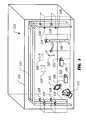
- FIG. 7is a stylized, exemplary view of representation of a virtual control panel within the virtual reality environment for use by the actor.
- one or more users or actors 101interact with one or more physical objects 103 and/or 105 in a physical or real environment and/or one or more virtual artifacts 107 and/or 109 in the virtual reality environment.
- the one or more actors 101are physically present in a three-dimensional space, known as a studio 111 in which the one or more actors 101 may move the one or more physical objects 103 and/or 105 .
- a motion capture environment 113is contained by studio 111 .
- Motion capture environment 113includes one or more computers 115 and software resident on the one or more computers 115 that are operable to generate virtual reality scenes.
- Motion capture environment 113further includes a framework 117 , upon which to mount tracker-sensors 119 and/or tracker-sensor combinations, which are described in greater detail herein.
- the softwareincludes one or more computer programs that interpret information from the tracker-sensors and one or more computer programs that create the virtual reality scenes or environment.
- a virtual representation of studio 111exists in motion capture environment 113 , which hosts the virtual reality environment.
- the one or more actors 101use display devices, for example, headset viewers, such as a headset viewer 201 of FIG. 2 ; monitors, such as a monitor 121 ; or the like, to view the virtual reality environment.
- the virtual reality environmentis the scene that the one or more actors 101 , or other such observers, see via the display devices.
- the virtual reality environmentmay be a virtual representation of the studio or the virtual reality environment may be a virtual representation of any other real or imagined three-dimensional space.
- the virtual reality environmentmay be a combination of a virtual representation of the studio and a virtual representation of another real or imagined three-dimensional space.
- Physical objectssuch as physical objects 103 and 105 , that are disposed within studio 111 and that are moved by the one or more actors 101 , are tracked using motion capture environment 113 .
- These “tracked objects”may be tracked by a variety of sensor methodologies, including, but not limited to, reflectors, such as reflectors 123 and 125 and reflector 203 of FIG. 2 ; inertial measurement units; and the like. Examples of such inertial measurement units include, but are not limited to, ring laser gyroscopes, accelerometers, ultrasonic emitter-receptors, and the like. Referring to FIG.
- examples of tracked objectsinclude, but are not limited to, wands, such as a wand 205 ; gloves, such as a glove 207 ; hats, such as a hat 209 ; head mounted displays, such as headset viewer 201 ; boots, such as boot 211 ; and the like.
- Tracker-sensorssuch as tracker sensors 119 , interface with motion capture environment 113 and determine where a tracked object, such as physical objects 103 and 105 , is located within the physical space of the studio.
- a tracked objectsuch as physical objects 103 and 105
- Such tracker-sensorsmay comprise a single unit or a plurality of units.
- the tracker-sensorsmay be attached to a framework, such as framework 117 , which defines the physical limits of the studio or may be attached to the tracked objects, or both. While tracker-sensors may utilize various methodologies for tracking tracked objects, certain tracker-sensors use inertial acceleration with subsequent integration to provide rate and displacement information, ultrasonic measurement, optical measurement, near infrared measurement, as well as methods that use other bands of radiation within the electromagnetic spectrum.
- motion capture environment 113has an interface 301 to an analysis system 303 .
- analysis systemsinclude, but are not limited to, a computational fluid dynamics system, a computational stress analysis system, a finite element analysis system, and the like.
- analysis systems 303There are innumerable types of analysis systems 303 that may be interfaced with motion capture environment 113 .
- Motion capture environment 113generates a virtual reality environment or scene that includes data from analysis system 303 , so that the actor, such as actor 101 , may interact with the virtual representation of the analysis data.
- the analysis datamay be represented in many dimensions, such as three physical dimensions, e.g., height, length, depth; color; sound; and the like.
- Wands 205 , gloves 207 , hat 209 , boots 211 , and the likeare tracked by the tracker-sensors.
- the process or device to be observedis generated by analysis system 303 and the resulting geometry is sent from the analysis program to the virtual reality scene, created by motion capture environment 113 , via interface 301 .
- Actor 101can observe the object and can touch the object in a virtual sense.
- Actor 101can reorient himself or herself relative to the object, the object can be resized for detailed inspection of a portion of the object or for an overall impression.
- these actionsare accomplished via a virtual control panel 127 , shown in FIGS. 1 and 7 , which is discussed in greater detail herein.
- the actionsmay be accomplished by actual virtual manipulation of the object by actor 101 .
- a virtual objectmay be modified in real time by actor 101 and the results shown immediately.
- FIG. 4an actor, such as actor 101 , within a virtual reality environment observes a virtual beam 401 being subjected to certain conditions within a modal analysis system, which is one type of analysis system 303 (shown in FIG. 3 ).
- the modal analysis systemdetermines the response of virtual beam 401 to the applied conditions and sends the resulting geometrical output to the virtual reality scene.
- Motion of virtual beam 401is depicted in the virtual reality environment in time and space.
- actor 101may attempt to modify virtual beam 401 by calling up a virtual toolbox, such as a virtual toolbox 501 , that contains, for example, virtual tuning weights. Actor 101 may select one of the virtual tuning weights and place it on virtual beam 401 . Actor 101 may request a new modal analysis. Preferably, the results of the new analysis display immediately, as if actor 101 had actually, physically placed a real, physical weight 601 on a real vibrating beam 603 , as shown in FIG. 6 . If the weight is insufficient or placed incorrectly, actor 101 can continue to iterate the mass and placement of the weight until the vibration levels are acceptable.
- a virtual toolboxsuch as a virtual toolbox 501
- the results of the new analysisdisplay immediately, as if actor 101 had actually, physically placed a real, physical weight 601 on a real vibrating beam 603 , as shown in FIG. 6 . If the weight is insufficient or placed incorrectly, actor 101 can continue to iterate the mass and placement of the weight until the vibration levels are acceptable
- a virtual control panelsuch as the displayed representation of virtual control panel 127 , also known as a synthetic remote control, exists as a virtual artifact only in the virtual reality environment and is produced by motion capture environment 113 .
- Virtual control panel 127is a virtual object displayed by the display device, such as headset viewer 201 of FIG. 2 , used by actor 101 to see the virtual reality environment.
- Virtual control panel 127may also be displayed on other display devices, such as monitor 121 of FIG. 1 , that can be viewed by those that are not actors.
- virtual control panel 127is a virtual means for inputting information to motion capture environment 113 by actor 101 . For example, as shown in FIG.
- virtual control panel 127comprises a plurality of controls that may be manipulated by actor 101 .
- the controlsinclude, but are not limited to, for example, buttons 701 , 703 , and 705 ; switches 707 and 709 ; and knobs 711 and 713 , which may be manipulated by actor 101 .
- virtual control panel 127may include additional or alternative controls that may be manipulated by actor 101 .
- virtual control panel 127may include one or more means for providing information from motion capture environment 113 to actor 101 .
- virtual control panel 127may provide information relating to a simulation being performed to actor 101 , such as a color scale or graph 715 representing certain parameter levels or a textual display 716 providing other such information.
- virtual control panel 127may comprise other tools which can be utilized by actor 101 in the virtual reality environment.
- virtual control panel 127may provide a virtual ruler 717 , which can be used by actor 101 to measure virtual artifacts, distances between virtual artifacts, or the like.
- the virtual control panelis able to “float” in virtual space at a location specified by actor 101 and may be moved from one place in the virtual environment to another place in the virtual environment by actor 101 .
- the controlsmay be manipulated by actor 101 's virtual hand, defined by a glove, such as glove 207 , best shown in FIG. 2 .
- Representations or “markers” 719 , 721 , 723 , and 725 , corresponding to a reflector from a glove worn by actor 101are also illustrated in FIG. 7 .
- the manipulation of the controlis detected by interpreting the motion of the actor's virtual hand when the actor's virtual hand is in “touching” proximity to the control, as determined by motion capture environment 113 .
- Motion capture environment 113determines how the control has been manipulated and reacts to the manipulation appropriately.
- actor 101 in studio 111manipulates a virtual hand in the virtual reality environment by wearing and physically moving glove 207 , best shown in FIG. 2 , which is a tracked object.
- Motion capture environment 113interprets the motion of the glove and determines where actor 101 's virtual hand is located in the virtual reality environment and how the virtual hand is oriented.
- actor 101wears headset viewer 201 , best shown in FIG. 2 , that is equipped with a synthetic vision viewer.
- the synthetic vision viewerdisplays to actor 101 the virtual reality environment and the location of the virtual hand within the virtual reality environment.
- actor 101can see the virtual hand in the context of the scene of the virtual reality environment.
- actor 101is wearing headset viewer 201 and glove 207 .
- Actor 101is reaching into empty physical space to press a button, such as one of buttons 701 , 703 , or 705 , of virtual control panel 127 .
- Virtual control panelis preferably positioned at some starting location within the virtual reality environment or may be opened and displayed at any convenient location within the virtual reality environment when actor 101 issues a command “summoning” virtual control panel 127 .
- Tracker-sensors 119track the location of glove 207 , best shown in FIG. 2 , and, thus, the virtual hand in the virtual reality environment and compare the location of the virtual hand in the virtual reality environment to the locations of the virtual control panel's controls in the virtual reality environment. When a collision is detected between the virtual hand and a virtual control of virtual control panel 127 , the virtual hand is deemed to be touching the control.
- Motion capture environment 113responds to the motion of the virtual hand and a mapping of a control state to a desired action causes the desired action to occur, just as if a physical or real hand had manipulated a physical or real control.
- Actor 101can operate a virtual control of virtual control panel 127 in the same way actor 101 can physically operate a tangible, physical object or control capable of being physically touched and physically manipulated. It should be noted that touching buttons, knobs, switches, and the like of the virtual control panel is but one way of interacting with the virtual control panel.
- virtual control panel 127can grow and shrink in size and capability without limit. Furthermore, virtual control panel 127 can be made to disappear or reappear at the will of actor 101 , without interfering with the scene in the virtual reality environment. Virtual control panel 127 is able to float at any location and orientation desired by actor 101 .
- the interactive display of data in motion capture environment 113provides many advantages to a virtual reality experience.
- the display of data in three-dimensional spaceis more intuitive and allows the user to see phenomena that may be hidden in two-dimensional representations of three-dimensional data.
- the display of three-dimensional data in three-dimensional spacemakes observing all surfaces of the object easier. Surfaces that may be difficult or impossible to see in a real world setting are more easily inspected in a virtual environment.
- virtual objectsare infinitely re-orientable and scalable by the actor in the virtual environment, so that experts are more closely integrated with the analysis.
- Virtual scenes incorporating analysis dataprovide the potential to link analytic solutions to displays for interactive virtual experimentation.
- motion capture environment 113comprises one or more computers, such as computer 115 , executing software embodied in a computer-readable medium that is operable to produce and control the virtual reality environment.
- the scope of the inventionencompasses, among other things, motion capture environment, such as motion capture environment 113 of FIG. 1 ; the software operable to produce and control the virtual reality environment; and the method for producing and controlling the virtual reality environment, carried out by motion capture environment 113 .
Landscapes
- Engineering & Computer Science (AREA)
- Theoretical Computer Science (AREA)
- General Engineering & Computer Science (AREA)
- General Physics & Mathematics (AREA)
- Physics & Mathematics (AREA)
- Human Computer Interaction (AREA)
- Software Systems (AREA)
- Computer Hardware Design (AREA)
- Computer Graphics (AREA)
- Multimedia (AREA)
- Processing Or Creating Images (AREA)
- User Interface Of Digital Computer (AREA)
- Image Analysis (AREA)
- Length Measuring Devices By Optical Means (AREA)
Abstract
Description
Claims (17)
Priority Applications (1)
| Application Number | Priority Date | Filing Date | Title |
|---|---|---|---|
| US12/522,641US8599194B2 (en) | 2007-01-22 | 2008-01-22 | System and method for the interactive display of data in a motion capture environment |
Applications Claiming Priority (3)
| Application Number | Priority Date | Filing Date | Title |
|---|---|---|---|
| US88605907P | 2007-01-22 | 2007-01-22 | |
| PCT/US2008/051661WO2008091869A2 (en) | 2007-01-22 | 2008-01-22 | System and method for the interactive display of data in a motion capture environment |
| US12/522,641US8599194B2 (en) | 2007-01-22 | 2008-01-22 | System and method for the interactive display of data in a motion capture environment |
Publications (2)
| Publication Number | Publication Date |
|---|---|
| US20100053152A1 US20100053152A1 (en) | 2010-03-04 |
| US8599194B2true US8599194B2 (en) | 2013-12-03 |
Family
ID=39645122
Family Applications (1)
| Application Number | Title | Priority Date | Filing Date |
|---|---|---|---|
| US12/522,641Active2028-10-27US8599194B2 (en) | 2007-01-22 | 2008-01-22 | System and method for the interactive display of data in a motion capture environment |
Country Status (5)
| Country | Link |
|---|---|
| US (1) | US8599194B2 (en) |
| EP (1) | EP2111606A4 (en) |
| CA (1) | CA2675999C (en) |
| DE (1) | DE08713901T1 (en) |
| WO (1) | WO2008091869A2 (en) |
Cited By (20)
| Publication number | Priority date | Publication date | Assignee | Title |
|---|---|---|---|---|
| US20130246565A1 (en)* | 2011-09-19 | 2013-09-19 | Qualcomn Incorporated | Sending human input device commands over internet protocol |
| WO2018156087A1 (en)* | 2017-02-27 | 2018-08-30 | National University Of Singapore | Finite-element analysis augmented reality system and method |
| US11297423B2 (en) | 2018-06-15 | 2022-04-05 | Shure Acquisition Holdings, Inc. | Endfire linear array microphone |
| US11297426B2 (en) | 2019-08-23 | 2022-04-05 | Shure Acquisition Holdings, Inc. | One-dimensional array microphone with improved directivity |
| US11303981B2 (en) | 2019-03-21 | 2022-04-12 | Shure Acquisition Holdings, Inc. | Housings and associated design features for ceiling array microphones |
| US11302347B2 (en) | 2019-05-31 | 2022-04-12 | Shure Acquisition Holdings, Inc. | Low latency automixer integrated with voice and noise activity detection |
| US11310592B2 (en) | 2015-04-30 | 2022-04-19 | Shure Acquisition Holdings, Inc. | Array microphone system and method of assembling the same |
| US11310596B2 (en) | 2018-09-20 | 2022-04-19 | Shure Acquisition Holdings, Inc. | Adjustable lobe shape for array microphones |
| US11438691B2 (en) | 2019-03-21 | 2022-09-06 | Shure Acquisition Holdings, Inc. | Auto focus, auto focus within regions, and auto placement of beamformed microphone lobes with inhibition functionality |
| US11445294B2 (en) | 2019-05-23 | 2022-09-13 | Shure Acquisition Holdings, Inc. | Steerable speaker array, system, and method for the same |
| US11477327B2 (en) | 2017-01-13 | 2022-10-18 | Shure Acquisition Holdings, Inc. | Post-mixing acoustic echo cancellation systems and methods |
| US11523212B2 (en) | 2018-06-01 | 2022-12-06 | Shure Acquisition Holdings, Inc. | Pattern-forming microphone array |
| US11552611B2 (en) | 2020-02-07 | 2023-01-10 | Shure Acquisition Holdings, Inc. | System and method for automatic adjustment of reference gain |
| US11558693B2 (en) | 2019-03-21 | 2023-01-17 | Shure Acquisition Holdings, Inc. | Auto focus, auto focus within regions, and auto placement of beamformed microphone lobes with inhibition and voice activity detection functionality |
| US11678109B2 (en) | 2015-04-30 | 2023-06-13 | Shure Acquisition Holdings, Inc. | Offset cartridge microphones |
| US11706562B2 (en) | 2020-05-29 | 2023-07-18 | Shure Acquisition Holdings, Inc. | Transducer steering and configuration systems and methods using a local positioning system |
| US11785380B2 (en) | 2021-01-28 | 2023-10-10 | Shure Acquisition Holdings, Inc. | Hybrid audio beamforming system |
| US12028678B2 (en) | 2019-11-01 | 2024-07-02 | Shure Acquisition Holdings, Inc. | Proximity microphone |
| US12250526B2 (en) | 2022-01-07 | 2025-03-11 | Shure Acquisition Holdings, Inc. | Audio beamforming with nulling control system and methods |
| US12289584B2 (en) | 2021-10-04 | 2025-04-29 | Shure Acquisition Holdings, Inc. | Networked automixer systems and methods |
Families Citing this family (4)
| Publication number | Priority date | Publication date | Assignee | Title |
|---|---|---|---|---|
| US9182812B2 (en)* | 2013-01-08 | 2015-11-10 | Ayotle | Virtual sensor systems and methods |
| WO2015172227A1 (en) | 2014-05-13 | 2015-11-19 | Pcp Vr Inc. | Method, system and apparatus for generation and playback of virtual reality multimedia |
| JP6725805B2 (en)* | 2015-02-13 | 2020-07-22 | スワン ソリューションズ インコーポレーテッド | System and method for controlling a terminal |
| US10607391B2 (en)* | 2018-07-04 | 2020-03-31 | International Business Machines Corporation | Automated virtual artifact generation through natural language processing |
Citations (33)
| Publication number | Priority date | Publication date | Assignee | Title |
|---|---|---|---|---|
| US5999185A (en) | 1992-03-30 | 1999-12-07 | Kabushiki Kaisha Toshiba | Virtual reality control using image, model and control data to manipulate interactions |
| US6308565B1 (en) | 1995-11-06 | 2001-10-30 | Impulse Technology Ltd. | System and method for tracking and assessing movement skills in multidimensional space |
| US20020010571A1 (en) | 1999-02-17 | 2002-01-24 | Daniel William E. | Systems and methods for interactive virtual reality process control and simulation (IVRPCS) |
| US20020010734A1 (en) | 2000-02-03 | 2002-01-24 | Ebersole John Franklin | Internetworked augmented reality system and method |
| WO2002021451A1 (en) | 2000-09-07 | 2002-03-14 | Neochi Llc | Method and system for simultaneously creating and using multiple virtual reality programs |
| US6538655B1 (en)* | 1997-08-29 | 2003-03-25 | Kabushiki Kaisha Sega Enterprises | Image processing system and image processing method |
| GB2385238A (en) | 2002-02-07 | 2003-08-13 | Hewlett Packard Co | Using virtual environments in wireless communication systems |
| US6624853B1 (en) | 1998-03-20 | 2003-09-23 | Nurakhmed Nurislamovich Latypov | Method and system for creating video programs with interaction of an actor with objects of a virtual space and the objects to one another |
| US6681629B2 (en) | 2000-04-21 | 2004-01-27 | Intersense, Inc. | Motion-tracking |
| US20040080507A1 (en) | 2000-09-13 | 2004-04-29 | Bernd Von Prittwitz | Freely specifiable real-time control |
| US20040104935A1 (en) | 2001-01-26 | 2004-06-03 | Todd Williamson | Virtual reality immersion system |
| US20040113885A1 (en) | 2001-05-31 | 2004-06-17 | Yakup Genc | New input devices for augmented reality applications |
| US6798407B1 (en) | 2000-11-28 | 2004-09-28 | William J. Benman | System and method for providing a functional virtual environment with real time extracted and transplanted images |
| US20050143172A1 (en) | 2003-12-12 | 2005-06-30 | Kurzweil Raymond C. | Virtual encounters |
| US20050166163A1 (en)* | 2004-01-23 | 2005-07-28 | Chang Nelson L.A. | Systems and methods of interfacing with a machine |
| US20050233865A1 (en) | 2002-09-03 | 2005-10-20 | Leonard Reiffel | Moving interactive virtual reality product |
| US20060001650A1 (en)* | 2004-06-30 | 2006-01-05 | Microsoft Corporation | Using physical objects to adjust attributes of an interactive display application |
| US20060087509A1 (en) | 2004-06-30 | 2006-04-27 | Ebert David S | Computer modeling and animation of natural phenomena |
| US7084884B1 (en)* | 1998-11-03 | 2006-08-01 | Immersion Corporation | Graphical object interactions |
| US20060192852A1 (en) | 2005-02-09 | 2006-08-31 | Sally Rosenthal | System, method, software arrangement and computer-accessible medium for providing audio and/or visual information |
| US20060228101A1 (en) | 2005-03-16 | 2006-10-12 | Steve Sullivan | Three-dimensional motion capture |
| US20060267932A1 (en) | 1994-07-12 | 2006-11-30 | Immersion Corporation | Force feedback device including coupling device |
| US20060290695A1 (en) | 2001-01-05 | 2006-12-28 | Salomie Ioan A | System and method to obtain surface structures of multi-dimensional objects, and to represent those surface structures for animation, transmission and display |
| US20070003915A1 (en) | 2004-08-11 | 2007-01-04 | Templeman James N | Simulated locomotion method and apparatus |
| US7372463B2 (en)* | 2004-04-09 | 2008-05-13 | Paul Vivek Anand | Method and system for intelligent scalable animation with intelligent parallel processing engine and intelligent animation engine |
| US7468778B2 (en)* | 2002-03-15 | 2008-12-23 | British Broadcasting Corp | Virtual studio system |
| US7885732B2 (en)* | 2006-10-25 | 2011-02-08 | The Boeing Company | Systems and methods for haptics-enabled teleoperation of vehicles and other devices |
| US7937253B2 (en)* | 2004-03-05 | 2011-05-03 | The Procter & Gamble Company | Virtual prototyping system and method |
| US7952594B2 (en) | 2004-05-27 | 2011-05-31 | Canon Kabushiki Kaisha | Information processing method, information processing apparatus, and image sensing apparatus |
| US8018579B1 (en) | 2005-10-21 | 2011-09-13 | Apple Inc. | Three-dimensional imaging and display system |
| US8073479B2 (en) | 2007-04-25 | 2011-12-06 | Nokia Corporation | System, method, and computer program product for service and application configuration in a network device |
| US20110320567A1 (en) | 2001-06-05 | 2011-12-29 | Xdyne, Inc. | Networked computer system for communicating and operating in a virtual reality environment |
| US8241118B2 (en) | 2006-01-27 | 2012-08-14 | Great Play Holdings Llc | System for promoting physical activity employing virtual interactive arena |
Family Cites Families (1)
| Publication number | Priority date | Publication date | Assignee | Title |
|---|---|---|---|---|
| US6999185B1 (en)* | 1999-11-22 | 2006-02-14 | Xerox Corporation | System and method for merging together jobs in a multi-platform printing system when one of the platforms is in a degraded mode |
- 2008
- 2008-01-22CACA2675999Apatent/CA2675999C/enactiveActive
- 2008-01-22DEDE08713901Tpatent/DE08713901T1/enactivePending
- 2008-01-22WOPCT/US2008/051661patent/WO2008091869A2/enactiveApplication Filing
- 2008-01-22EPEP08713901.0Apatent/EP2111606A4/ennot_activeCeased
- 2008-01-22USUS12/522,641patent/US8599194B2/enactiveActive
Patent Citations (33)
| Publication number | Priority date | Publication date | Assignee | Title |
|---|---|---|---|---|
| US5999185A (en) | 1992-03-30 | 1999-12-07 | Kabushiki Kaisha Toshiba | Virtual reality control using image, model and control data to manipulate interactions |
| US20060267932A1 (en) | 1994-07-12 | 2006-11-30 | Immersion Corporation | Force feedback device including coupling device |
| US6308565B1 (en) | 1995-11-06 | 2001-10-30 | Impulse Technology Ltd. | System and method for tracking and assessing movement skills in multidimensional space |
| US6538655B1 (en)* | 1997-08-29 | 2003-03-25 | Kabushiki Kaisha Sega Enterprises | Image processing system and image processing method |
| US6624853B1 (en) | 1998-03-20 | 2003-09-23 | Nurakhmed Nurislamovich Latypov | Method and system for creating video programs with interaction of an actor with objects of a virtual space and the objects to one another |
| US7084884B1 (en)* | 1998-11-03 | 2006-08-01 | Immersion Corporation | Graphical object interactions |
| US20020010571A1 (en) | 1999-02-17 | 2002-01-24 | Daniel William E. | Systems and methods for interactive virtual reality process control and simulation (IVRPCS) |
| US20020010734A1 (en) | 2000-02-03 | 2002-01-24 | Ebersole John Franklin | Internetworked augmented reality system and method |
| US6681629B2 (en) | 2000-04-21 | 2004-01-27 | Intersense, Inc. | Motion-tracking |
| WO2002021451A1 (en) | 2000-09-07 | 2002-03-14 | Neochi Llc | Method and system for simultaneously creating and using multiple virtual reality programs |
| US20040080507A1 (en) | 2000-09-13 | 2004-04-29 | Bernd Von Prittwitz | Freely specifiable real-time control |
| US6798407B1 (en) | 2000-11-28 | 2004-09-28 | William J. Benman | System and method for providing a functional virtual environment with real time extracted and transplanted images |
| US20060290695A1 (en) | 2001-01-05 | 2006-12-28 | Salomie Ioan A | System and method to obtain surface structures of multi-dimensional objects, and to represent those surface structures for animation, transmission and display |
| US20040104935A1 (en) | 2001-01-26 | 2004-06-03 | Todd Williamson | Virtual reality immersion system |
| US20040113885A1 (en) | 2001-05-31 | 2004-06-17 | Yakup Genc | New input devices for augmented reality applications |
| US20110320567A1 (en) | 2001-06-05 | 2011-12-29 | Xdyne, Inc. | Networked computer system for communicating and operating in a virtual reality environment |
| GB2385238A (en) | 2002-02-07 | 2003-08-13 | Hewlett Packard Co | Using virtual environments in wireless communication systems |
| US7468778B2 (en)* | 2002-03-15 | 2008-12-23 | British Broadcasting Corp | Virtual studio system |
| US20050233865A1 (en) | 2002-09-03 | 2005-10-20 | Leonard Reiffel | Moving interactive virtual reality product |
| US20050143172A1 (en) | 2003-12-12 | 2005-06-30 | Kurzweil Raymond C. | Virtual encounters |
| US20050166163A1 (en)* | 2004-01-23 | 2005-07-28 | Chang Nelson L.A. | Systems and methods of interfacing with a machine |
| US7937253B2 (en)* | 2004-03-05 | 2011-05-03 | The Procter & Gamble Company | Virtual prototyping system and method |
| US7372463B2 (en)* | 2004-04-09 | 2008-05-13 | Paul Vivek Anand | Method and system for intelligent scalable animation with intelligent parallel processing engine and intelligent animation engine |
| US7952594B2 (en) | 2004-05-27 | 2011-05-31 | Canon Kabushiki Kaisha | Information processing method, information processing apparatus, and image sensing apparatus |
| US20060087509A1 (en) | 2004-06-30 | 2006-04-27 | Ebert David S | Computer modeling and animation of natural phenomena |
| US20060001650A1 (en)* | 2004-06-30 | 2006-01-05 | Microsoft Corporation | Using physical objects to adjust attributes of an interactive display application |
| US20070003915A1 (en) | 2004-08-11 | 2007-01-04 | Templeman James N | Simulated locomotion method and apparatus |
| US20060192852A1 (en) | 2005-02-09 | 2006-08-31 | Sally Rosenthal | System, method, software arrangement and computer-accessible medium for providing audio and/or visual information |
| US20060228101A1 (en) | 2005-03-16 | 2006-10-12 | Steve Sullivan | Three-dimensional motion capture |
| US8018579B1 (en) | 2005-10-21 | 2011-09-13 | Apple Inc. | Three-dimensional imaging and display system |
| US8241118B2 (en) | 2006-01-27 | 2012-08-14 | Great Play Holdings Llc | System for promoting physical activity employing virtual interactive arena |
| US7885732B2 (en)* | 2006-10-25 | 2011-02-08 | The Boeing Company | Systems and methods for haptics-enabled teleoperation of vehicles and other devices |
| US8073479B2 (en) | 2007-04-25 | 2011-12-06 | Nokia Corporation | System, method, and computer program product for service and application configuration in a network device |
Non-Patent Citations (23)
| Title |
|---|
| "Surround-Screen Projection-based Virtual Reality: The Design and Implementation of the CAVE", Carolina Cruz-Neira, Computer Graphics: Annual Conference Series, New York, NY No. 20th, Aug. 1, 1993, pp. 135-142, XP002660833. |
| Advisory action from U.S. Appl. No. 12/595,373 dated Nov. 2, 2012. |
| Extended European Search Report in related European patent application No. 08713901.0, mailed Jun. 28, 2013, 6 pages. |
| Extended European Search Report in related European patent application No. 08733207.8, mailed Jul. 2, 2013, 5 pages. |
| First Examination Report from the Canadian Intellectual Property Office in related Canadian application No. 2,675,999, mailed Jul. 5, 2012, 2 pages. |
| First Examination Report from the Canadian Patent Office in related Canadian application 2,675,995, mailed May 2, 2013, 4 pages. |
| First Examination Report from the Canadian Patent Office in related Canadian application 2,684,487, mailed Apr. 24, 2013, 3 pages. |
| International Preliminary Examination Report in PCT Application PCT/US08/51651, dated Jul. 6, 2009, 7 pages. |
| International Preliminary Report on Patentability in Parent PCT Application PCT/US08/51661, dated Dec. 29, 2008, 7 pages. |
| International Preliminary Report on Patentability in PCT Application PCT/US08/51642, dated Dec. 29, 2008, 7 pages. |
| International Preliminary Report on Patentability in PCT Application PCT/US08/60562, dated Feb. 18, 2010, 7 pages. |
| International Search Report and Written Opinion in Parent PCT Application PCT/US08/51661, dated Jul. 1, 2008, 6 pages |
| International Search Report and Written Opinion in PCT Application PCT/US08/51642, dated Jun. 27, 2008, 7 pages. |
| International Search Report and Written Opinion in PCT Application PCT/US08/51651, dated Jun. 27, 2008, 6 pages. |
| International Search Report and Written Opinion in PCT Application PCT/US08/60562, dated Aug. 15, 2008, 7 pages. |
| Office Action from U.S. Appl. No. 12/522,568 dated Aug. 2, 2012. |
| Office Action from U.S. Appl. No. 12/522,620 dated Apr. 12, 2012. |
| Office Action from U.S. Appl. No. 12/522,620 dated Oct. 9, 2012. |
| Office action from U.S. Appl. No. 12/595,373 dated Aug. 15, 2012. |
| Office Action in U.S. Appl. No. 12/522,620, dated Oct. 31, 2011, 9 pages. |
| Office Action in U.S. Appl. No. 12/595,373, dated Feb. 17, 2012, 8 pages. |
| SpotON: An Indoor 3D Location Sensing Technology Based on RF Signal Strength, by Hightower et al., University of Washington Computer Science and Engineering Technical Report #2000-02-02, Feb. 18, 2000, 16 pages. |
| Supplementary European Search Report in European Application No. 08713892, dated Sep. 29, 2010, 5 pages. |
Cited By (33)
| Publication number | Priority date | Publication date | Assignee | Title |
|---|---|---|---|---|
| US9106651B2 (en)* | 2011-09-19 | 2015-08-11 | Qualcomm Incorporated | Sending human input device commands over internet protocol |
| US20130246565A1 (en)* | 2011-09-19 | 2013-09-19 | Qualcomn Incorporated | Sending human input device commands over internet protocol |
| US11678109B2 (en) | 2015-04-30 | 2023-06-13 | Shure Acquisition Holdings, Inc. | Offset cartridge microphones |
| US12262174B2 (en) | 2015-04-30 | 2025-03-25 | Shure Acquisition Holdings, Inc. | Array microphone system and method of assembling the same |
| US11832053B2 (en) | 2015-04-30 | 2023-11-28 | Shure Acquisition Holdings, Inc. | Array microphone system and method of assembling the same |
| US11310592B2 (en) | 2015-04-30 | 2022-04-19 | Shure Acquisition Holdings, Inc. | Array microphone system and method of assembling the same |
| US11477327B2 (en) | 2017-01-13 | 2022-10-18 | Shure Acquisition Holdings, Inc. | Post-mixing acoustic echo cancellation systems and methods |
| US12309326B2 (en) | 2017-01-13 | 2025-05-20 | Shure Acquisition Holdings, Inc. | Post-mixing acoustic echo cancellation systems and methods |
| WO2018156087A1 (en)* | 2017-02-27 | 2018-08-30 | National University Of Singapore | Finite-element analysis augmented reality system and method |
| US11800281B2 (en) | 2018-06-01 | 2023-10-24 | Shure Acquisition Holdings, Inc. | Pattern-forming microphone array |
| US11523212B2 (en) | 2018-06-01 | 2022-12-06 | Shure Acquisition Holdings, Inc. | Pattern-forming microphone array |
| US11770650B2 (en) | 2018-06-15 | 2023-09-26 | Shure Acquisition Holdings, Inc. | Endfire linear array microphone |
| US11297423B2 (en) | 2018-06-15 | 2022-04-05 | Shure Acquisition Holdings, Inc. | Endfire linear array microphone |
| US11310596B2 (en) | 2018-09-20 | 2022-04-19 | Shure Acquisition Holdings, Inc. | Adjustable lobe shape for array microphones |
| US12425766B2 (en) | 2019-03-21 | 2025-09-23 | Shure Acquisition Holdings, Inc. | Auto focus, auto focus within regions, and auto placement of beamformed microphone lobes with inhibition and voice activity detection functionality |
| US12284479B2 (en) | 2019-03-21 | 2025-04-22 | Shure Acquisition Holdings, Inc. | Auto focus, auto focus within regions, and auto placement of beamformed microphone lobes with inhibition functionality |
| US11558693B2 (en) | 2019-03-21 | 2023-01-17 | Shure Acquisition Holdings, Inc. | Auto focus, auto focus within regions, and auto placement of beamformed microphone lobes with inhibition and voice activity detection functionality |
| US11778368B2 (en) | 2019-03-21 | 2023-10-03 | Shure Acquisition Holdings, Inc. | Auto focus, auto focus within regions, and auto placement of beamformed microphone lobes with inhibition functionality |
| US11303981B2 (en) | 2019-03-21 | 2022-04-12 | Shure Acquisition Holdings, Inc. | Housings and associated design features for ceiling array microphones |
| US11438691B2 (en) | 2019-03-21 | 2022-09-06 | Shure Acquisition Holdings, Inc. | Auto focus, auto focus within regions, and auto placement of beamformed microphone lobes with inhibition functionality |
| US11445294B2 (en) | 2019-05-23 | 2022-09-13 | Shure Acquisition Holdings, Inc. | Steerable speaker array, system, and method for the same |
| US11800280B2 (en) | 2019-05-23 | 2023-10-24 | Shure Acquisition Holdings, Inc. | Steerable speaker array, system and method for the same |
| US11302347B2 (en) | 2019-05-31 | 2022-04-12 | Shure Acquisition Holdings, Inc. | Low latency automixer integrated with voice and noise activity detection |
| US11688418B2 (en) | 2019-05-31 | 2023-06-27 | Shure Acquisition Holdings, Inc. | Low latency automixer integrated with voice and noise activity detection |
| US11750972B2 (en) | 2019-08-23 | 2023-09-05 | Shure Acquisition Holdings, Inc. | One-dimensional array microphone with improved directivity |
| US11297426B2 (en) | 2019-08-23 | 2022-04-05 | Shure Acquisition Holdings, Inc. | One-dimensional array microphone with improved directivity |
| US12028678B2 (en) | 2019-11-01 | 2024-07-02 | Shure Acquisition Holdings, Inc. | Proximity microphone |
| US11552611B2 (en) | 2020-02-07 | 2023-01-10 | Shure Acquisition Holdings, Inc. | System and method for automatic adjustment of reference gain |
| US12149886B2 (en) | 2020-05-29 | 2024-11-19 | Shure Acquisition Holdings, Inc. | Transducer steering and configuration systems and methods using a local positioning system |
| US11706562B2 (en) | 2020-05-29 | 2023-07-18 | Shure Acquisition Holdings, Inc. | Transducer steering and configuration systems and methods using a local positioning system |
| US11785380B2 (en) | 2021-01-28 | 2023-10-10 | Shure Acquisition Holdings, Inc. | Hybrid audio beamforming system |
| US12289584B2 (en) | 2021-10-04 | 2025-04-29 | Shure Acquisition Holdings, Inc. | Networked automixer systems and methods |
| US12250526B2 (en) | 2022-01-07 | 2025-03-11 | Shure Acquisition Holdings, Inc. | Audio beamforming with nulling control system and methods |
Also Published As
| Publication number | Publication date |
|---|---|
| CA2675999A1 (en) | 2008-07-31 |
| CA2675999C (en) | 2015-12-15 |
| US20100053152A1 (en) | 2010-03-04 |
| WO2008091869A9 (en) | 2009-09-03 |
| DE08713901T1 (en) | 2010-02-25 |
| EP2111606A4 (en) | 2013-07-31 |
| EP2111606A2 (en) | 2009-10-28 |
| WO2008091869A2 (en) | 2008-07-31 |
| WO2008091869A3 (en) | 2008-09-25 |
Similar Documents
| Publication | Publication Date | Title |
|---|---|---|
| US8599194B2 (en) | System and method for the interactive display of data in a motion capture environment | |
| CA2675276C (en) | System and method for controlling a virtual reality environment by an actor in the virtual reality environment | |
| EP3549109B1 (en) | Virtual user input controls in a mixed reality environment | |
| US10521028B2 (en) | System and method for facilitating virtual interactions with a three-dimensional virtual environment in response to sensor input into a control device having sensors | |
| JP6893868B2 (en) | Force sensation effect generation for space-dependent content | |
| Anthes et al. | State of the art of virtual reality technology | |
| KR101965454B1 (en) | System and method for virtual engineering | |
| JP2018136938A (en) | Automatic localized haptics generation system | |
| CN110476142A (en) | Virtual objects user interface is shown | |
| TW202101172A (en) | Arm gaze-driven user interface element gating for artificial reality systems | |
| KR20220018562A (en) | Gating Edge-Identified Gesture-Driven User Interface Elements for Artificial Reality Systems | |
| JP2010257081A (en) | Image processing method and image processing apparatus | |
| Kahaner | Japanese activities in virtual reality | |
| Onyesolu et al. | A survey of some virtual reality tools and resources | |
| Thalmann et al. | Virtual reality software and technology | |
| GB2539182A (en) | Dynamic augmented reality system | |
| EP2106572B1 (en) | System and method for performing multiple, simultaneous, independent simulations in a motion capture environment | |
| Tri Dung et al. | Collaboration Between Human–Robot Interaction Based on CDPR in a Virtual Reality Game Environment | |
| Hill | Reducing jerk for bimanual control with virtual reality | |
| Bibb | Determining principles for the development of mixed reality systems for command and control applications | |
| JP2005115430A (en) | Immersive design support apparatus and method | |
| Olive | Multiple degrees-of-freedom input devices for interactive command and control within virtual reality in industrial visualisations | |
| Yin | Evaluating multimodal feedback for accomplishing assembly tasks in virtual environment | |
| CN117133432A (en) | Medical device, interaction method thereof, virtual/augmented reality device, and storage medium | |
| Heukers | A Smartphone-based Controller for Virtual Reality Applications |
Legal Events
| Date | Code | Title | Description |
|---|---|---|---|
| AS | Assignment | Owner name:BELL HELICOPTER TEXTRON INC.,TEXAS Free format text:ASSIGNMENT OF ASSIGNORS INTEREST;ASSIGNORS:LEWIS, GEORGE STEVEN;VALENTINO, JOHN;BOTHWELL, CHRISTOPHER MICHAEL;REEL/FRAME:023026/0311 Effective date:20070424 Owner name:BELL HELICOPTER TEXTRON INC., TEXAS Free format text:ASSIGNMENT OF ASSIGNORS INTEREST;ASSIGNORS:LEWIS, GEORGE STEVEN;VALENTINO, JOHN;BOTHWELL, CHRISTOPHER MICHAEL;REEL/FRAME:023026/0311 Effective date:20070424 | |
| AS | Assignment | Owner name:TEXTRON INNOVATIONS INC., RHODE ISLAND Free format text:ASSIGNMENT OF ASSIGNORS INTEREST;ASSIGNOR:BELL HELICOPTER TEXTRON INC.;REEL/FRAME:025555/0107 Effective date:20100219 | |
| STCF | Information on status: patent grant | Free format text:PATENTED CASE | |
| AS | Assignment | Owner name:TEXTRON INNOVATIONS INC., RHODE ISLAND Free format text:ASSIGNMENT OF ASSIGNORS INTEREST;ASSIGNOR:BELL HELICOPTER TEXTRON INC.;REEL/FRAME:039862/0274 Effective date:20090529 | |
| FPAY | Fee payment | Year of fee payment:4 | |
| MAFP | Maintenance fee payment | Free format text:PAYMENT OF MAINTENANCE FEE, 8TH YEAR, LARGE ENTITY (ORIGINAL EVENT CODE: M1552); ENTITY STATUS OF PATENT OWNER: LARGE ENTITY Year of fee payment:8 | |
| MAFP | Maintenance fee payment | Free format text:PAYMENT OF MAINTENANCE FEE, 12TH YEAR, LARGE ENTITY (ORIGINAL EVENT CODE: M1553); ENTITY STATUS OF PATENT OWNER: LARGE ENTITY Year of fee payment:12 |