US8599143B1 - Switch configuration for detecting writing pressure in a writing device - Google Patents
Switch configuration for detecting writing pressure in a writing deviceDownload PDFInfo
- Publication number
- US8599143B1 US8599143B1US11/348,804US34880406AUS8599143B1US 8599143 B1US8599143 B1US 8599143B1US 34880406 AUS34880406 AUS 34880406AUS 8599143 B1US8599143 B1US 8599143B1
- Authority
- US
- United States
- Prior art keywords
- writing
- insert
- switch
- tip
- assembly
- Prior art date
- Legal status (The legal status is an assumption and is not a legal conclusion. Google has not performed a legal analysis and makes no representation as to the accuracy of the status listed.)
- Active, expires
Links
Images


Classifications
- G—PHYSICS
- G06—COMPUTING OR CALCULATING; COUNTING
- G06F—ELECTRIC DIGITAL DATA PROCESSING
- G06F3/00—Input arrangements for transferring data to be processed into a form capable of being handled by the computer; Output arrangements for transferring data from processing unit to output unit, e.g. interface arrangements
- G06F3/01—Input arrangements or combined input and output arrangements for interaction between user and computer
- G06F3/03—Arrangements for converting the position or the displacement of a member into a coded form
- G06F3/033—Pointing devices displaced or positioned by the user, e.g. mice, trackballs, pens or joysticks; Accessories therefor
- G06F3/0354—Pointing devices displaced or positioned by the user, e.g. mice, trackballs, pens or joysticks; Accessories therefor with detection of 2D relative movements between the device, or an operating part thereof, and a plane or surface, e.g. 2D mice, trackballs, pens or pucks
- G06F3/03545—Pens or stylus
Definitions
- Embodiments of the present inventionrelate to the field of interactive devices and pen based computing. More specifically, embodiments of the present invention relate to a switch configuration to detect writing pressure in an interactive writing device.
- Typical computing devicesprovide access to these interactive applications via a user interface.
- Typical computing deviceshave on-screen graphical interfaces that present information to a user using a display device, such as a monitor or display screen, and receive information from a user using an input device, such as a mouse, a keyboard, a joystick, or a stylus.
- New personal computing devicesare also being developed which use an interactive writing device to interact and non-interactive writing devices to interact with a writing surface.
- Various embodiments of the present inventionhave the above-described advantages and others that are described herein.
- an apparatus for detecting writing pressureis comprised of a carrier.
- a mode selection device coupled to the carrieris operable to select writing modes.
- a switch coupled to the carrieris operable to move between a first state and a second state in response to writing pressure coupled to the switch.
- An actuator coupled to the carrieris configured to actuate the switch in response to pressure applied to the actuator in response to writing.
- Various writing insertssuch as a multi-mode pen or a mechanical can be coupled to the carrier and operated with the mode switch.
- the mode switchcan be used to select an automatic feeding mode of a mechanical pencil, a manual feeding mode of a mechanical pencil, or a non-marking stylus mode of a mechanical pencil, or retracted and extended modes of a pen.
- a tipactivates the actuator in response to pressure applied to the tip.
- the switchis an electrical switch.
- the switchis made of a mylar type material.
- the switchcan detect varying levels of pressure.
- a writing insertis configured so that it can be coupled to a carrier.
- a tip coupled to the writing insertis configured to move a portion of the insert from a first position to a second position for the purpose of actuating a switch within the carrier in response to pressure applied to the tip.
- the writing devicealso has a mode selecting assembly configured for selecting modes of the writing insert.
- the mode selecting assemblycan select modes of a pen insert.
- the mode selecting assemblycan select modes of a mechanical pencil insert, such as automatic feed mode, manual feed mode, or non-marking stylus mode.
- the writing insertis keyed to automatically align within the carrier when inserted.
- the assemblyis comprised of a carrier that is configured to receive a writing insert, a writing insert that can be slid into and coupled with the carrier, and a switch coupled to the carrier.
- An actuator coupled to the carrieris configured to activate the switch in response to pressure applied to the actuator by the writing insert.
- a tip coupled to the writing insertis configured to slidably move a portion of the writing insert when pressure is applied to the tip.
- a mode selectoris coupled to the carrier and operable to select writing modes of the writing insert without interfering with the operation of the switch.
- the carrierdefines a channel for receiving the writing insert.
- the writing inserthas a plurality of ramps that interact with tabs on the carrier to rotatably key the writing insert.
- the switchis an electrical switch, which may be made of a mylar type material. In one embodiment the switch is a two-position switch. In one embodiment, the switch is a normally open switch. In one embodiment the switch senses varying levels of pressure applied to it.
- the writing insertis a pen insert and the mode selector can be used to select various writing modes of the pen insert. In another embodiment, the writing insert is a mechanical pencil insert, and the mode selector can be used to select various writing modes of the mechanical pencil.
- FIG. 1illustrates an exemplary interactive device according to an embodiment of the present invention.
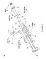
- FIG. 2shows an exemplary writing insert that can be utilized with embodiments of the present invention.
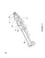
- FIG. 3is an exploded view of an exemplary writing insert holder according to an embodiment of the present invention.
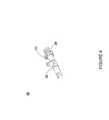
- FIG. 4shows an exemplary mode selecting assembly according to an embodiment of the present invention.
- FIG. 5shows an exemplary assembled writing insert holder in accordance with an embodiment of the present invention.
- FIG. 6shows an exemplary assembled writing insert holder coupled with an exemplary writing insert in accordance with an embodiment of the present invention.
- FIG. 7shows an exemplary assembled writing insert holder coupled with an exemplary writing insert in accordance with an embodiment of the present invention.
- FIG. 8shows a partial-sectional view displaying the inner workings of an exemplary writing insert in accordance with an embodiment of the present invention.
- FIG. 9shows an enlarged view of a clutch assembly and a tip assembly for an exemplary mechanical pencil in accordance with an embodiment of the present invention.
- FIG. 10shows an exemplary writing insert that can be utilized with embodiments of the present invention.
- FIG. 11shows a sectional view of an exemplary writing insert that can be utilized with embodiments of the present invention.
- FIG. 12shows a sectional view of an exemplary writing insert that can be utilized with embodiments of the present invention.
- FIG. 13shows an exemplary assembled writing insert holder coupled with an exemplary writing insert in accordance with an embodiment of the present invention.
- FIG. 14shows an exemplary assembled writing insert holder coupled with an exemplary writing insert in accordance with an embodiment of the present invention.
- FIG. 1is a block diagram of an interactive writing device 150 upon which other embodiments of the present invention can be implemented.
- interactive writing device 150may be referred to as an optical device, more specifically as an optical reader, optical pen, digital pen, or digital pencil.
- the devicemay contain a computer system and an operating system resident thereon. Application programs may also reside thereon.
- interactive writing device 150includes a processor 32 inside a housing 62 .
- housing 62has the form of a pen or other writing or marking utensil or instrument.
- Processor 32is operable for processing information and instructions used to implement the functions of interactive writing device 150 , which are described below.
- interactive writing device 150may include an audio output device 38 and an optional display device 40 coupled to the processor 32 .
- the audio output device and/or the display deviceare physically separated from interactive writing device 150 , but in communication with interactive writing device 150 through either a wired or wireless connection.
- interactive writing device 150can include a transceiver or transmitter (not shown in FIG. 1 ).
- the audio output device 36may include a speaker or an audio jack (e.g., for an earphone or headphone).
- the display device 40may be a liquid crystal display (LCD) or some other suitable type of display.
- interactive writing device 150may include input buttons 36 coupled to the processor 32 for activating and controlling the interactive writing device 150 .
- the input buttons 36allow a user to input information and commands to interactive writing device 150 or to turn interactive writing device 150 on or off.
- Interactive writing device 150also includes a power source 34 such as a battery.
- Interactive writing device 150also includes a light source or optical emitter 44 and a light sensor or optical detector 42 coupled to the processor 32 .
- the optical emitter 44may be a light emitting diode (LED), for example, and the optical detector 42 may be a charge coupled device (CCD) or complementary metal-oxide semiconductor (CMOS) imager array, for example.
- the optical emitter 44illuminates surface 70 or a portion thereof. Light reflected from the surface 70 is received at and recorded by optical detector 42 .
- the surface 70may be a sheet a paper, although the present invention is not so limited.
- a pattern of markingsis printed on surface 70 .
- the end of interactive writing device 150 that holds optical emitter 44 and optical detector 42is placed against or near surface 70 .
- the pattern of markingsare read and recorded by optical emitter 44 and optical detector 42 .
- the markings on surface 70are used to determine the position of interactive writing device 150 relative to surface.
- the markings on surface 70are used to encode information.
- the captured images of surface 70can be analyzed (processed) by interactive writing device 150 to decode the markings and recover the encoded information.
- Interactive writing device 150 of FIG. 1also includes a memory unit 48 coupled to the processor 32 .
- memory unit 48is a removable memory unit embodied as a memory cartridge or a memory card.
- memory unit 48includes random access (volatile) memory (RAM) and read-only (non-volatile) memory (ROM) for storing information and instructions for processor 32 .
- interactive writing device 150includes a writing element 52 situated at the same end of interactive writing device 150 as the optical detector 42 and the optical emitter 44 .
- Writing element 52can be, for example, a pen, pencil, marker, stylus, mechanical pencil, multi-mode writing device, or the like, and may or may not be retractable.
- Writing element 52may also be comprised of many parts such as a carrier (not shown) a removable writing insert (not shown).
- Writing element 52may also comprise a switch 55 to detect writing pressure.
- writing element 52is not needed.
- a usercan use writing element 52 to make marks (e.g., graphical elements or user-written selectable items) on surface 70 , including characters such as letters, words, numbers, mathematical symbols and the like.
- These markscan be scanned (imaged) and interpreted by interactive writing device 150 according to their position on the surface 70 .
- the position of the user-produced markscan be determined using a pattern of marks that are printed on surface 70 .
- the user-produced markingscan be interpreted by interactive writing device 150 using optical character recognition (OCR) techniques that recognize handwritten characters.
- OCRoptical character recognition
- FIG. 2shows an exemplary writing insert 200 that can be utilized with embodiments of the present invention.
- Writing insert 200is comprised of a tip assembly 205 which is coupled to a barrel enclosure assembly 210 , a guide 215 which is rotatably coupled to barrel enclosure assembly 210 , a slide which is slidably and rotatably coupled within guide 215 , and a reservoir 230 which is slidably and rotatably coupled within slide 220 , guide 215 and barrel enclosure 210 .
- Writing insert 200can be configured for use with interactive writing device 150 .
- tip assembly 205is threaded on one end and has a slidably coupled spring loaded tip 235 on the other end.
- Tip 235can be solid or hollow.
- Tip 235can comprise various forms such as an ink pen tip, a mechanical pencil tip, a stylus tip, or a combination tip such as a mechanical pencil tip that can also be used as a non-marking stylus.
- tip 235is a mechanical pencil tip that serves a dual role as a stylus when lead is retracted.
- tip assembly 205may be detachable from the remainder of writing insert 200 .
- tip assembly 205contains inner workings for a mechanical pencil, while in another embodiment, tip assembly 205 serves as a guide for a stylus or tip of an ink pen.
- barrel enclosure assembly 210contains portions of a mechanical pencil. In another embodiment, barrel enclosure assembly 210 contains portions of a pen (such as a retractable and extendable ink pen) or some other writing device such as a stylus or highlighter. Barrel enclosure assembly 210 is configured to move slidably in response to pressure applied to tip 235 .
- Guide 215is rotatably coupled to barrel enclosure assembly 210 in one embodiment of the present invention, and is configured to move slidably in response to pressure applied to one side from tip 235 .
- guide 215has four ramps 240 (two shown) for keying guide 215 with a carrier 305 ( FIG. 3 ).
- Guide 215also has a rim 245 for interfacing with an actuator 310 ( FIG. 3 ) to transfer pressure to actuator 310 from tip 235 .
- guide 215also comprises an L-shaped channel 255 in which a snap 250 of slide 220 traverses to select writing modes of writing insert 200 .
- the L-Shaped channel 255 configuration of guide 215has two stop points, or detent positions, the first position is pointed to by arrow 251 , while snap 250 is shown locked into the second position. It should be appreciated that more selectable configurations and stop points are possible in other embodiments simply by changing the shape of the channel in guide 215 .
- Guide 215 shown in FIG. 2is exemplary, and it should be noted that in other embodiments of the present invention, guide 215 can be longer or shorter than shown.
- Slide 220is slidably and rotatably coupled within guide 215 and is configured to move in response to force applied to tip 235 .
- Snap 250 of slide 220traverses within a channel 255 of guide 215 , which defines and limits the sliding and rotation of slide 220 .
- One end of slide 220has teeth 260 (two shown, but more are possible) which can be acted on by a mode selector such as mode selector 325 ( FIG. 3 ) to slide and rotate slide 220 for the purpose of interacting with spring loaded internal workings (not shown) located inside barrel enclosure assembly 210 .
- slide 220can manipulate the internal workings for selecting and engaging various possible writing modes of writing insert 200 .
- Spring force coupled through the internal workingspushes slide 220 outward until it is either stopped by snap 250 at the top of channel 255 , shown by arrow 251 , or locked via spring force against a lower edge of channel 255 , as shown by the position of snap 250 in FIG. 3 .
- the combination of slide 220 , guide 215 , and the internal spring force of writing insert 200comprises a mode selecting assembly within writing insert 200 that works in conjunction with mode selector assembly 400 ( FIG. 4 ) to select operating modes of writing device 200 .
- Reservoir 230is for containing writing materiel such as a supply of leads, ink, or highlighter fluid. Reservoir 230 is slidably and rotatably coupled within slide 220 and is configured to move in response to force applied to tip 235 and also in response to pressure applied to slide 220 by mode button 325 ( FIG. 3 ). Reservoir 230 can be of various lengths in other embodiments, and is optional in embodiments where it not needed (such as for a stylus only writing insert) or where its functions are performed by a reservoir that fits internally within barrel enclosure assembly 210 .
- exemplary writing insert 200is shown as an automatically feeding mechanical pencil, with a selectable non-marking stylus writing mode. These two modes of operation, automatic pencil and non-marking stylus, are selected based on the stop position that snap 250 is placed in.
- the automatic feed pencil modeis selected by placing snap 250 into position 251 in L-shaped channel 255 .
- the mechanical pencilcan be caused to manually feed lead, which can be considered a temporarily selectable third mode.
- snap 250By sliding snap 250 in direction 252 and then rotating snap 250 in direction 253 , snap 250 can be placed in the second stop position (this is the location of snap 250 as shown in FIG. 2 ), and a non-marking stylus mode can be selected.
- other types of writing insertssuch as ink pens can be used. Similar guide and snap arrangements also allow various modes of operation of an ink pen, for example, to be selected. For instance, with an ink pen writing insert, a first position of a snap can retract a pen tip for storage, thus allowing the writing insert to be used as a non-marking stylus, while a second position of a snap can extend a pen tip for writing.
- FIG. 3is an exploded view of an exemplary writing insert holder 300 according to an embodiment of the present invention.
- FIG. 3is utilized to show and describe the separate parts and features of writing insert holder 300 .
- An assembled version of writing insert 300is shown in FIG. 5 and is useful for understanding some of the interactions of the parts described in conjunction with FIG. 3 .
- Writing insert holder 300is comprised of a carrier 305 , actuator, 310 , spring clip 315 , spring 320 , mode button 325 , and switch 55 .
- Carrier 305may be constructed from an injection molded plastic material but can be comprised of other suitable materials and manufacturing processes.
- Carrier 305defines a channel 306 for receiving a writing insert (not shown) on one end and mode button 325 on the other end.
- One end of carrier 305may contain treads such as threads 307 for securing a tip assembly (not shown) or for securing a writing insert such as a pen, stylus, mechanical pencil, or other writing instrument.
- Carrier 305comprises tabs 308 for interacting with a portion of a writing insert (not shown) to rotatably orient a writing insert as it is slidably inserted into carrier 305 .
- Carrier 305defines a recess 309 for housing an actuator and a switch such as actuator 310 and switch 55 .
- Carrier 305also has a slot (not shown) for allowing pass through of a portion of switch 55 .
- Carrier 305comprises a lip 316 and protrusion 317 for orienting and securing spring clip 315 .
- Carrier 305also defines a guide 327 that interacts with a snap 326 on mode button 325 to slidably orient mode button 325 within channel 306 and to secure mode button 325 into a rotatably selectable position or positions within channel 306 .
- Switch 55is constructed of a flexible plastic type material such as mylar, with a printed conductive pattern.
- One end 56 of switch 55defines an oval shaped hole that takes the shape of a semicircular cutout when folded for insertion into recess 309 .
- the normal position (as shown) for switch 55is open, or non conductive, however other embodiments can use a normally closed switch.
- One advantage a normally open switchis power savings, because electricity is only conducted when the switch is closed due to writing pressure. When the folded end 56 of switch 55 is fully compressed, the conductive pattern is shorted out, and switch 55 becomes a closed circuit.
- switch 55creates a spring force that causes switch 55 to spring back to the open position (shown) when no (or low) external forces are acting to keep switch 55 forcibly closed.
- the non-folded end of switch 55slips through a slot (not shown) in the bottom of recess 309 and can be attached to circuitry of interactive writing device 150 , such as processor 32 .
- Switch 55 as showis a two-position switch, but other embodiments can utilize a switch that has more positions, or a switch that senses varying levels of pressure.
- An advantage to using a switch that detects varying levels of pressureis the ability to measure how much force a user applies when writing. This can be used to provide emphasis to a computer-generated version of user written items recorded by an interactive writing device.
- Actuator 310has tabs 311 for aligning within recess 309 .
- Tabs 311are slidably coupled to recess 309
- the cylindrical body of actuator 310is slidably disposed within channel 306 .
- the cylindrical body of actuator 310fits over the folded end 56 of switch 55 and retains the folded portion 56 in recess 306 .
- the toothed end of mode button 325is inserted into one end of actuator 310 , while a toothed portion 260 ( FIG. 2 ) of a writing insert 200 ( FIG. 2 ) can be partially inserted the other end of actuator 310 .
- An inkwell or lead storage reservoir 230 ( FIG. 2 ) of the writing insert 200 ( FIG. 2 )can protrude partially or completely through the center of actuator 310 and onward into or through the hollow cylindrical center of mode button 325 .
- Mode button 325is slidably and rotatably coupled within channel 306 with the toothed end protruding slightly into actuator 310 .
- Snap 326which protrudes from mode button 325 , interfaces with guide 327 to slidably orient mode button 325 and to secure mode button 325 in a rotatably selectable position.
- Spring clip 315slides onto mode button 325 as does spring 320 .
- Spring 320is then compressed between spring clip 315 and tabs 328 (two shown, but more or less are possible) at the end of mode button 325 . Force from spring 320 acts on tabs 328 to pull mode button 325 in a direction away from actuator 310 , and cause snap 326 to lock into stops (not shown) in guide 327 .
- FIG. 4shows an assembled exemplary mode selector assembly 400 in accordance with an embodiment of the present invention.
- Mode selector assembly 400is comprised of mode button 325 , spring clip 315 and spring 320 .
- the functionality of mode selector assembly 400is as described in conjunction with the individual parts of mode selector assembly 400 , which were shown and described in FIG. 3 .
- FIG. 5shows an exemplary assembled writing insert holder 300 in accordance with an embodiment of the present invention.
- FIG. 5illustrates how the parts of FIG. 3 are assembled in to a holder 300 which can be coupled to an interactive writing device such as interactive writing device 150 .
- Writing instrument holder 300is comprised of a carrier 305 , actuator 310 , spring clip 315 , spring 320 , mode selector button 325 , and switch 55 .
- various mounting posts and holesare also visible (not labeled) and can be utilized to couple writing insert holder with interactive writing device 150 and other devices and assemblies.
- the embodiment shownis exemplary, and other suitable means may be used to couple writing insert holder 300 to other devices and assemblies.
- FIG. 5also shows mode selector assembly 400 installed and oriented in carrier 305 . Note that teeth 329 ( FIG. 3 ) of mode selector button 325 are disposed within actuator 310 , and that mode selector button can freely slide and rotate within actuator 310 .
- FIG. 6shows an exemplary assembled writing insert holder 300 coupled with an exemplary writing insert 200 in accordance with an embodiment of the present invention.
- the teeth 329 ( FIG. 3 ) of selector button 325are disposed within actuator 310 .
- the teeth 260 ( FIG. 2 ) of slide 220are also disposed within actuator 310 .
- This arrangementallows force to be manually applied with mode selector button 325 through the hollow center of pass through actuator 310 .
- the forcecan be applied to a portion of a writing insert, such as the teeth 260 of slide 220 or teeth 1060 of slide 1020 ( FIG. 10 ), that is slidably disposed partially within the hollow center of pass through actuator 310 , without transferring any force to actuator 310 or switch 55 .
- Mode selection button 325can slide and rotate slide 220 into various positions that will then be locked-in by internal spring force from writing insert 200 acting to wedge snap 250 into guide 255 , when pressure from mode selection button 325 is removed.
- mode selection button 325advantageously allows various modes of a writing insert to be selected without interrupting or interfering with the functionality of switch 55 , which is used to detect writing pressure. Additionally, after manual force on mode selection button 325 is released, spring 320 pulls mode selection button 325 slightly away from slide 220 , and into a selected stop point that snap 326 ( FIG. 3 ) is aligned with in channel 327 ( FIG. 3 ). By pulling mode selection button away from slide 220 , mode selection button 325 is prevented from interfering with any sliding motion imparted to any portion of writing insert 200 by tip 235 .
- FIG. 6also illustrates the interaction of ramps 240 (one visible) with tabs 308 , to cause writing insert to self-align when inserted in carrier 305 .
- ramps 240one visible
- tabs 308to cause writing insert to self-align when inserted in carrier 305 .
- only two alignmentsare possible, 180 degrees apart from one another.
- the interaction between rim 245 of guide 215 and actuator 310are appreciable. For example, as pressure applied in direction 610 to moveable tip 235 (for instance by writing), transferred force causes guide 215 to slidably move in direction 610 and interface with actuator 310 to close switch 55 . When pressure from tip 235 is released, spring force from folded switch 55 forces switch 55 to an open position and pushes actuator 310 and guide 255 back toward tip 235 .
- Switch 55is operable to detect writing pressure when mode button 325 and snap 250 , of slide 220 , are locked in a first position, such as an automatic feed mode of a mechanical pencil.
- a stylus insert or a writing insertsuch as a pen, pencil, marker, chalk or crayon is utilized in a manner that interfaces only with actuator 310 , but not with mode selector assembly 400 in any manner for the purpose of changing operating modes.
- a stylus insert or writing inserthas a surface that interfaces with actuator 310 to pass writing force applied to the writing instrument into actuator 310 to close switch 55 in response to writing. Movements of mode button 325 have no mode altering effect on the writing insert in this embodiment of the invention.
- a single mode embodiment, such as this,is useful for instance with large writing instruments such as crayons, markers, or chalks, but can also be utilized with a stylus or other writing instruments.
- FIG. 7shows an exemplary assembled writing insert holder 300 coupled with an exemplary writing insert 200 in accordance with an embodiment of the present invention.
- mode button 325 and snap 250 of slide 220are locked in a second position.
- this second positionis a non-marking stylus mode of the mechanical pencil insert 200 that is shown.
- writing pressureis applied directly to tip 235
- a lead feeding modewriting pressure is applied tip 235 through writing with a lead that extends from tip 235 .
- changing modes of operationimparts no force or movement to switch 55 or actuator 310 . This is because force from spring 320 and mode button 325 are isolated from actuator 310 , and in addition, internal spring forces from writing insert 200 are isolated from actuator 310 by snap 250 which limits sliding motion of the internal components of writing insert 200 .
- guide 215is still located in the same position relative to actuator 310 as it was in FIG. 6 .
- this same arrangementis employable to isolate mode selecting force from a pressure sensing switch in other writing inserts, such as pen insert that can change from a retracted to an extended mode of operation.
- mode selection forces and a writing insert's internal spring forces from switch 255 and actuator 310By decoupling mode selection forces and a writing insert's internal spring forces from switch 255 and actuator 310 , as described, more functionality such as a plurality of operational modes can be added to a writing insert and selected for operation, without interfering with a writing pressure sensing switch, such as switch 55 , due to spring forces in the insert or forces exerted by the mode selector. Further, a switch such as switch 55 continues to operate unimpeded, throughout the plurality of selectable modes of a writing device or writing insert.
- FIG. 8shows a partial-sectional view displaying the inner workings of an exemplary writing insert 200 in accordance with an embodiment of the present invention.
- writing insert 200is configured as an automatically feeding mechanical pencil with a manual feed capability and a selectable non-marking stylus mode of operation.
- Writing insert 200is configured to insert into a carrier and operate with a pressure sensing switch assembly for use with an interactive writing device.
- writing insert 200can be configured as a stand alone multi-mode writing device, or as a multimode stylus for use with a computer or personal digital assistant (PDA).
- PDApersonal digital assistant
- Writing inert 200is comprised of a slide 220 that is rotatably and slidably coupled to a guide 215 (both previously described), a lead tube/reservoir 230 , a tube 850 , a main spring 830 , a barrel enclosure 815 , a clutch assembly 810 , and a tip assembly 205 .
- Tip assembly 205is comprised of a tip housing 840 and an inner tip assembly 820 . Reference to FIG. 2 and previously described elements will be made in the description of writing insert 200 shown in FIG. 8 .
- Slide 220is slidably and rotatably coupled with guide 230 and contains a snap 250 for securing slide 220 into selectable positions corresponding to writing modes of writing insert 200 .
- Slide 220is also slidably and rotatably coupled to reservoir 230 and tube 850 .
- Snap 250moves slidably and rotatably within a channel 255 ( FIG. 2 ) defined in guide 215 .
- Snap 250can secure slide 220 into position 251 ( FIG. 2 ), which corresponds to a mechanical pencil automatic feeding mode, or into a second position corresponding to a mechanical pencil non-marking stylus mode (shown by the position of snap 250 in FIG. 2 ).
- An edge of slide 220interfaces with collar 851 , which supplies spring force from main spring 830 to secure slide 220 into selectable positions.
- Guide 215is rotatably coupled to barrel enclosure 815 , either by threads or a press fit or some other suitable secure manner.
- This secure couplingcontains the spring force from main spring 830 , which is supplied to slide 220 and locks snap 250 into selectable positions within channel 255 ( FIG. 2 ) of guide 215 .
- Reservoir 230is for storing a supply of leads for writing and for supplying one lead at a time to clutch assembly 810 . Reservoir 230 is securely coupled within tube 850 , either by a press fit or some other removable or permanent means.
- Tube 850is for securing reservoir 230 .
- Tube 850also comprises collar 851 , which is for retaining one end of main spring 830 and transferring force from main spring 830 to slide 220 .
- Tube 850also defines an opening 852 for securing a portion of clutch halves 917 and 918 (described in FIG. 9 ), and for allowing the passage of leads from reservoir 230 toward clutch assembly 810 .
- Tube 850is partially disposed within barrel enclosure 815 , and one end is also partially disposed within clutch assembly 810 .
- Main spring 830is compressed between collar 851 and stop 860 , and supplies force to slide 220 , which is utilized to cause slide 220 to rebound from manual compression by a user (for example, with mode button 325 of FIG. 3 ) and also to secure slide 220 into selectable positions in guide 215 , as previously described.
- Barrel enclosure 815is made of metal, but can also be made of other suitable materials. Barrel enclosure 815 also comprises stop 860 . In one embodiment barrel enclosure 815 has a threaded end for coupling to guide 215 . In one embodiment, guide 215 is rotatably coupled to barrel enclosure 815 . Barrel enclosure 815 provides an outer housing for a portion of tube 850 and for clutch assembly 810 .
- Clutch assembly 810is disposed within barrel enclosure 815 and is used for securing a lead, which is used for writing. Clutch assembly 810 may also interchangeably be referred to as a brake assembly. One end of clutch assembly 810 is coupled to tube 850 , while the other end is coupled to tip assembly 205 . Functionality of clutch assembly 810 is more completely described in conjunction with FIG. 9 .
- Tip assembly 205is comprised of a tip housing 840 that has threads or other securing means for coupling to a housing or a carrier such as carrier 305 ( FIG. 3 ). Tip assembly 205 is also comprised of inner tip assembly 820 that is used for guiding, securing, and automatically feeding a lead. Inner tip assembly 820 is described more completely in conjunction with FIG. 9 .
- FIG. 9shows an enlarged view of a clutch assembly 810 and a tip assembly 205 for an exemplary mechanical pencil in accordance with an embodiment of the present invention.
- Clutch assembly 810is comprised of a housing 911 , two clutch halves 917 and 918 , a spring 913 , two bearings 914 and 915 , and two ribs 931 and 932 .
- Clutch assembly 810is for securing and releasing a lead, and is particularly configured to securely grip and engage colored leads, such as blue leads, which are softer and more slippery than commonly used graphite type leads.
- Other embodimentsutilize a clutch assembly with features configured for gripping normal graphite leads.
- Clutch assembly 810is engaged and disengaged by pressure provided via a coupling to tube 850 ( FIG. 8 ). In one embodiment of the present invention, tube 850 transmits force from mode button 325 ( FIG. 3 ) to clutch assembly 810 .
- Housing 911is a tube used for housing clutch halves 917 and 918 , main spring 913 , bearings 914 and 915 , and ribs 931 and 932 .
- Housing 911defines a stop 919 , which stops one end of spring 913 , and a conical ramp 916 that serves as a guide for bearings 914 and 915 .
- Housing 911is slidably disposed within barrel enclosure 815 ( FIG. 8 ), and couples with stop 860 ( FIG. 8 ) to transmit writing pressure from tip assembly 205 into barrel enclosure 815 and upward to guide 215 ( FIG. 8 ).
- Clutch halves 917 and 918are slidably coupled within housing 911 and mate together to define a somewhat cylindrical opening 933 for a lead to pass through, and to grip a lead with.
- Clutch halves 917 and 918each have a recess for receiving a bearing such as bearings 914 and 915 .
- bearings 914 and 914are spherically shaped metal balls.
- clutch halves 917 and 918each define a semi-circular half of stop 912 , which is used to provide a stop for an end of spring 913 .
- clutch halves 917 and 918When clutch halves 917 and 918 are closed together and engaged (as shown) in a first position, a lead can be secured between the two halves by contact points within the defined somewhat cylindrical opening, and thus prevented from moving in direction 951 when writing pressure is applied to a lead.
- Forcecan be applied to clutch halves 917 and 918 via tube 850 ( FIG. 8 ), which slidably couples into opening 934 .
- Opening 852 in tube 850couples with clutch halves 917 and 918 .
- This spreadingis controlled by the interaction between bearings 914 and 915 , conical opening 916 , and the halves of clutch 917 and 918 .
- the spreading of the clutch halvesallows the lead, previously gripped by clutch halves 917 and 918 to be released or disengaged.
- Ribs 931 and 932act to prevent bearings 914 and 915 from dislodging as they slidably interface with the wall of conical opening 916 .
- the surfaces of the clutch halves 917 and 918are configured to grip colored lead (such as blue lead), which is more slippery than ordinary graphite lead. This can be done by adding grooves to the surfaces used for gripping the lead, by other means such as using a material that does not slide when gripping a colored lead, or by manufacturing the halves 917 and 918 so that opening 933 is slightly smaller or tapered at one end.
- Other embodiments of the present inventionutilize clutch halves 917 and 918 that are configured for gripping graphite type leads.
- slide 220is shown secured into a non-marking stylus position, which compresses spring 913 , slides clutch halves 917 and 918 in direction 950 , and allows a lead to freely slide between the disengaged clutch halves 917 and 918 within clutch assembly 810 .
- clutch halves 917 and 918are moved in direction 951 by spring force from spring 913 acting on collar 912 and assume a position as shown in FIG. 9 , where a lead is securely engaged and gripped for automatic feeding in conjunction with tip assembly 205 .
- FIG. 9also shows a tip assembly 205 , that is comprised of a tip housing 840 and an inner tip assembly 820 .
- Inner tip assembly 820is used to guide and automatically feed a lead, in a manner conventionally known in the art.
- Inner tip assembly 820is comprised of a bushing 921 , a plunger 922 , a retaining ring 923 , a spring 924 , and hollow tip 235 .
- Retaining ring 923is slidably coupled to tip 235 and secures inner tip assembly 820 inside tip housing 840 through a means such as a press fit against the inner wall 941 of tip housing 840 .
- Retaining ring 923also serves as a stop for one end of spring 924 .
- Tip 235is hollow, has a cylindrical opening for lead to pass through, and can be constructed of metal, plastic, or other suitable materials. Tip 235 is slidably movable relative to tip housing 840 in response to writing pressure applied to a lead extending from tip 235 or in response to writing pressure applied directly to tip 235 . Tip 235 also comprises a circular stop 925 , which provides a stop for one end of spring 924 . Plunger 922 and bushing 921 are fixedly coupled to tip 235 . Plunger 922 has a lip 926 that slightly overlaps bushing 921 , to trap bushing 921 between plunger 922 and tip 235 . Plunger 922 interfaces with housing 911 , in response to writing pressure, to transfer motion from tip 235 to housing 911 . In one embodiment of the present invention, bushing 921 is made of a resilient material such as a silicon, plastic, or rubber material.
- Tip 235slidably moves in direction 951 , in response to writing pressure, thus compressing spring 924 between retaining ring 923 and circular stop 925 .
- clutch assembly 810If clutch assembly 810 is engaged, and thus gripping a lead, bushing 921 will slide in direction 951 along the lead in response to writing pressure. However if clutch assembly 810 is disengaged, writing pressure will cause the lead to slide in direction 951 within bushing 921 , until no lead extends from tip 235 .
- spring 924moves tip 235 back in direction 950 , and bushing 921 grips a lead (not shown) and moves in direction 950 .
- clutch assembly 810When clutch assembly 810 is engaged, the sliding and gripping of bushing 921 works in conjunction with clutch assembly 810 to automatically advance lead in response to writing pressure. In this automatic feed mode, a lead continually slightly feeds out tip 235 to replenish lead used up by writing.
- Tip assembly 205transmits writing force pressure from tip 235 in direction 951 .
- non-writing (stylus) modewriting pressure is transmitted from plunger 922 to a first end of clutch housing 911 .
- writing pressureis transmitted from the lead directly into clutch 810 , which is gripping the lead.
- a second end of the clutch housing 911interfaces with stop 860 and transfers writing force pressure into barrel enclosure 815 .
- Barrel enclosure 815transfers the writing force pressure to guide 215 .
- Guide 215then moves in direction 951 in response to writing force pressure applied to tip 235 .
- applying writing force to tip 235causes guide 215 to engage actuator 310 and activate writing pressure switch 55 .
- FIG. 10shows an exemplary pen insert 1000 that can be utilized with embodiments of the present invention.
- Pen insert 1000is comprised of a tip 1035 , a tip housing 1005 , a barrel 1010 , a guide 1015 , and a slide 1020 .
- Slide 1020is comprised of teeth 1060 , and snap 1060 .
- Guide 1015is comprised of teeth 1040 , rim 1045 , and channel 1055 .
- Pen insert 1000is described in conjunction with FIGS. 11-14 .
- FIG. 11shows a sectional view of an exemplary pen insert 1000 that can be utilized with embodiments of the present invention.
- Pen insert 1000is comprised of slide 1020 , guide 1015 , barrel 1010 , snap 1050 , reservoir shaft 1070 , spring 1075 , tip housing 1005 , and tip 1035 .
- the exterior form factor of pen insert 1000is very similar to that of writing insert 200 ( FIG. 2 ).
- writing insert 200 and pen insert 1000are both are exchangably couplable with writing insert holder 300 shown in FIG. 3 .
- Tip 1035is a stylus tip or a writing tip, such as a ball point, roller ball, or other type of pen tip. Tip 1035 is shown retracted with in tip housing 1005 , but can also be extended from tip housing 1005 for writing. Tip housing 1005 slidably and rotatably couples with barrel 1010 . Tip housing 1005 also comprises threads or some other means which can be used to couple tip housing 1005 to a carrier, such as carrier 305 of writing insert holder 300 ( FIG. 3 ). Tip 1035 is coupled with reservoir shaft 1070 , which contains a supply of ink for pen tip 1035 . Reservoir shaft 1070 is slidably and rotatably coupled within barrel 1010 . Reservoir shaft 1070 is also fixedly coupled to slide 1020 by a means such as a press fit. In yet another embodiment of the present invention, tip 1035 is a non-marking stylus, and reservoir shaft 1070 is an empty shaft.
- reservoir shaft 1070 and pen tip 1035are slidably disposed within an optional thin hollow sleeve 1105 that protrudes from barrel 1010 and extends slightly out of tip 1035 .
- the hollow sleeve 1105can be utilized as a non-marking stylus when pen tip 1035 is retracted within sleeve 1105 (as shown in FIG. 11 ). While pen tip 1035 is retracted, writing pressure applied to sleeve 1105 is coupled from sleeve 1105 , through barrel 1010 , and into guide 1015 . The transference of writing pressure causes guide 1015 to move in direction 1055 . In an embodiment where writing insert 1000 is inserted into writing insert holder 300 ( FIG. 3 ), writing force that moves guide 1015 in direction 1055 will cause rim 1045 to interface with actuator 310 and close switch 55 (see FIG. 3 ).
- Guide 1015comprises self-aligning teeth 1040 (similar to teeth 240 in FIG. 2 ) that interact with ramps, such as ramps 308 ( FIG. 3 ), when pen insert 1000 is inserted into a carrier 305 ( FIG. 3 ) to automatically align pen insert 1000 into the proper orientation. Although two self-aligning teeth 1040 are shown, more can be used in other embodiments. Guide 1015 also comprises a rim 1045 (similar to rim 245 of FIG. 2 ) for interacting with an actuator such as actuator 310 of FIG. 3 . Guide 1015 is formed in a single piece with barrel 1010 and can be made of a material such as injection molded plastic.
- guide 1015 and barrel 1010can be manufactured as separate pieces and then fixedly coupled together by a means such as threaded ends.
- Guide 1015also defines a channel 1055 , which in this embodiment is L-shaped and has two stop points ( 1051 and 1052 ). In other embodiments, channel 1055 can have other shapes with more stop points.
- Slide 1020comprises snap 1050 and teeth 1060 .
- Slide 1020is slidably and rotatably coupled within guide 1015 . Sliding and rotating of slide 1020 are limited and defined by the movement of snap 1050 within channel 1055 of guide 1015 .
- Force exerted on slide 1020 in direction 1052 and direction 1053slides and rotates snap 1050 from a first position 1051 to a second position 1052 , within channel 1055 .
- spring 1075is compressed.
- Spring 1052provides force to wedge slide 1055 in stop positions 1051 and 1052 , within channel 1055 .
- Spring 1075also provides force to move snap 1050 from position 1052 to position 1051 when slide 1020 is used to rotate snap 1050 in direction 1054 from position 1052 .
- tip 1035is retracted within tip housing 1005 .
- Snap 1050 and guide 1015work in concert to isolate spring force of spring 1075 within guide 1015 .
- Teeth 1060which are similar to teeth 260 in FIG. 2 , are for interfacing with a mode selection button, such as mode selection button 325 of FIG. 3 . By interfacing with a mode selection button, teeth 1060 receive force to slide and rotate slide 1020 .
- FIG. 12shows a sectional view of an exemplary pen insert 1000 that can be utilized with embodiments of the present invention.
- FIG. 12is analogous to FIG. 11 except that slide 1020 has been used to move snap 1050 from position 1051 to position 1052 in channel 1055 .
- Spring 1075is now compressed and tip 1035 is now extended from tip housing 1005 past the end of sleeve 1105 , and can be used for marking and writing.
- Writing pressure on tip 1035is transmitted up the shaft of reservoir shaft 1070 to guide 1015 .
- the transference of writing pressurecauses guide 1015 to move in direction 1055 .
- writing force that moves guide 1015 in direction 1055will cause rim 1045 to interface with actuator 310 and close switch 55 (see FIG. 3 ).
- Such an arrangementis shown in and described in FIG. 14 .
- FIG. 13shows an exemplary assembled writing insert holder 300 coupled with an exemplary writing insert 1000 in accordance with an embodiment of the present invention.
- FIG. 13differs from FIG. 6 in that writing insert 1000 has internal workings of an extendable and retractable ink pen instead of the mechanical pencil internal workings of writing insert 200 .
- exemplary writing insert 1000shares a similar external form factor and functionality with writing insert 200 for all parts that interface with writing insert holder 300 for selecting writing modes, sensing writing pressure, and orienting a writing insert.
- tip 1035in a retracted position and not shown
- tip 235 of writing insert 200merely changes modes of operation instead of extending and retracting.
- writing insert holder 300interfaces with writing insert 1000 in the same fashion as described in FIG. 6 .
- the teeth 329 ( FIG. 3 ) of selector button 325are disposed within actuator 310 .
- This arrangementallows force to be manually applied with mode selector button 325 through the center of pass through actuator 310 to a portion of a writing insert; such as the teeth 1060 (not visible, but the same as shown in FIG. 10 ) of slide 1020 , without transferring any force to actuator 310 or switch 55 .
- Mode selection button 325can slide and rotate slide 1020 (not visible) into various positions that will then be locked-in by internal spring force from spring 1075 ( FIG. 11 ) in writing insert 1000 , thus acting to wedge snap 1050 into L-shaped guide 1055 , when pressure from mode selection button 325 is removed.
- This arrangementadvantageously allows various modes of a writing insert such as the extendable and retractable pen shown in FIGS. 10 and 11 to be selected without interrupting or interfering with the functionality of switch 55 , which is used to detect writing pressure.
- retracted modehas been selected by moving snap 1050 to position 1051 in L-shaped channel 1055 of guide 1015 .
- spring 320pulls mode selection button 325 slightly away from slide 1020 (not visible), and into a selected stop point that snap 326 ( FIG. 3 ) is aligned with in channel 327 ( FIG. 3 ).
- FIG. 13also illustrates the interaction of ramps 1040 (one visible) with tabs 308 , to cause writing insert 1000 to self-align when inserted in carrier 305 of writing insert 300 .
- This aligningis the same as described in conjunction with FIG. 6 . In the configuration shown, only two alignments are possible, 180 degrees apart from one another. In other embodiments with more ramps, more orientations are possible.
- FIG. 14shows an exemplary assembled writing insert holder 300 coupled with an exemplary writing insert 1000 in accordance with an embodiment of the present invention.
- snap 1050 of slide 1020 and mode button 325are each locked in a second position.
- the second position 1052 of snap 1050causes the inner working of writing insert 1000 to extend tip 1035 from the retracted position of FIG. 13 .
- the change in modes of mode button 325also causes spring 320 to be compressed.
- changing modes of operationimparts no force or movement to switch 55 or actuator 310 .
- force from spring 320 and mode button 325are isolated from actuator 310 , and in addition, internal spring forces from writing insert 1000 are isolated from actuator 310 by snap 1050 which limits sliding motion of the internal components of writing insert 1000 .
- guide 1015is still located in the same position relative to actuator 310 as it was in FIG. 13 .
- writing pressure on tip 1035is detectable at switch 55 through actuator 310 , in a similar manner as described in conjunction with FIG. 6 .
- the interaction between rim 1045 of guide 1015 and actuator 310 in response to writing pressure on tip 1035is appreciable.
- transferred forcecauses guide 1015 to slidably move in direction 1310 and interface with actuator 310 to close switch 55 .
- Switch 55is operable to detect writing pressure when mode button 325 and snap 1050 are locked in a second position 1052 (shown in FIG. 14 ) which causes tip 1035 to be extended.
- spring force from folded switch 55forces switch 55 to an open position and pushes actuator 310 and guide 1055 back toward tip 1035 .
- Tip 1035is also pushed to its fully extended position (as shown in FIG. 14 ). No part of the interaction between tip 1035 , actuator 310 , and switch 55 is interfered with by the selection of writing modes via mode button 325 . Further, switch 55 is only closed and activated in response to pressure (such as writing pressure) applied to tip 1035 , at all other times, switch 55 is in an open position.
- pressuresuch as writing pressure
Landscapes
- Engineering & Computer Science (AREA)
- General Engineering & Computer Science (AREA)
- Theoretical Computer Science (AREA)
- Human Computer Interaction (AREA)
- Physics & Mathematics (AREA)
- General Physics & Mathematics (AREA)
- Mechanical Pencils And Projecting And Retracting Systems Therefor, And Multi-System Writing Instruments (AREA)
Abstract
Description
Claims (9)
Priority Applications (1)
| Application Number | Priority Date | Filing Date | Title |
|---|---|---|---|
| US11/348,804US8599143B1 (en) | 2006-02-06 | 2006-02-06 | Switch configuration for detecting writing pressure in a writing device |
Applications Claiming Priority (1)
| Application Number | Priority Date | Filing Date | Title |
|---|---|---|---|
| US11/348,804US8599143B1 (en) | 2006-02-06 | 2006-02-06 | Switch configuration for detecting writing pressure in a writing device |
Publications (1)
| Publication Number | Publication Date |
|---|---|
| US8599143B1true US8599143B1 (en) | 2013-12-03 |
Family
ID=49640753
Family Applications (1)
| Application Number | Title | Priority Date | Filing Date |
|---|---|---|---|
| US11/348,804Active2030-03-05US8599143B1 (en) | 2006-02-06 | 2006-02-06 | Switch configuration for detecting writing pressure in a writing device |
Country Status (1)
| Country | Link |
|---|---|
| US (1) | US8599143B1 (en) |
Cited By (7)
| Publication number | Priority date | Publication date | Assignee | Title |
|---|---|---|---|---|
| US20140078105A1 (en)* | 2012-09-14 | 2014-03-20 | Samsung Electronics Co., Ltd | Stylus pen, input processing method using the same, and electronic device therefor |
| US20140253461A1 (en)* | 2013-03-11 | 2014-09-11 | Barnesandnoble.Com Llc | Stylus control feature for locking/unlocking touch sensitive devices |
| US20150116290A1 (en)* | 2013-10-25 | 2015-04-30 | Livescribe Inc. | Combined activation mechanism of retractable marker and power status for an electronic pen |
| US20160048224A1 (en)* | 2014-08-18 | 2016-02-18 | Samuel Brunet | Low-Power and Low-Frequency Data Transmission for Stylus and Associated Signal Processing |
| US11042250B2 (en)* | 2013-09-18 | 2021-06-22 | Apple Inc. | Dynamic user interface adaptable to multiple input tools |
| US11079862B2 (en) | 2014-08-18 | 2021-08-03 | Wacom Co., Ltd. | Low-power and low-frequency data transmission for stylus and associated signal processing |
| US20220365614A1 (en)* | 2021-05-12 | 2022-11-17 | Chicony Electronics Co., Ltd. | Stylus pen |
Citations (129)
| Publication number | Priority date | Publication date | Assignee | Title |
|---|---|---|---|---|
| US2182334A (en) | 1939-02-18 | 1939-12-05 | Crespo Joseph | Panoramic device |
| US2932907A (en) | 1956-01-16 | 1960-04-19 | Joseph A Stieber | Map projections demonstrator |
| US3292489A (en) | 1964-07-09 | 1966-12-20 | Ibm | Hierarchical search system |
| US3304612A (en) | 1963-12-23 | 1967-02-21 | Union Oil Co | Method and apparatus for converting cartograph coordinates to permanent digital form |
| US3530241A (en) | 1966-09-07 | 1970-09-22 | Marconi Co Ltd | Electrical position resolver arrangements |
| US3591718A (en) | 1968-04-18 | 1971-07-06 | Shintron Co Inc | Graphical input tablet |
| US3798370A (en) | 1972-04-17 | 1974-03-19 | Elographics Inc | Electrographic sensor for determining planar coordinates |
| US3888311A (en) | 1973-10-01 | 1975-06-10 | Exxon Production Research Co | Hydraulic fracturing method |
| US3911215A (en) | 1974-03-18 | 1975-10-07 | Elographics Inc | Discriminating contact sensor |
| US3921165A (en) | 1973-03-21 | 1975-11-18 | Ibm | High resolution graphic data tablet |
| US4079194A (en) | 1976-08-09 | 1978-03-14 | Victor Kley | Graphical data entry pad |
| US4220815A (en) | 1978-12-04 | 1980-09-02 | Elographics, Inc. | Nonplanar transparent electrographic sensor |
| US4425099A (en) | 1981-10-13 | 1984-01-10 | Texas Instruments Incorporated | Educational aid for use with workbook |
| US4492819A (en) | 1982-12-30 | 1985-01-08 | Kurta Corporation | Graphic tablet and method |
| US4570149A (en) | 1983-03-15 | 1986-02-11 | Koala Technologies Corporation | Simplified touch tablet data device |
| US4603231A (en) | 1983-03-31 | 1986-07-29 | Interand Corporation | System for sensing spatial coordinates |
| US4619539A (en)* | 1984-02-13 | 1986-10-28 | Kotobuki & Co, Ltd. | Mechanical pencil equipped with lead-storing cartridge |
| US4630209A (en) | 1981-07-01 | 1986-12-16 | Toyota Jidosha Kogyo Kabushiki Kaisha | Audio/visual display system for multiple maps |
| US4650926A (en) | 1984-10-26 | 1987-03-17 | Scriptel Corporation | Electrographic system and method |
| US4706090A (en) | 1984-01-27 | 1987-11-10 | Hitachi Zosen Corp | Ship collision preventive aid apparatus |
| US4739299A (en) | 1986-01-17 | 1988-04-19 | Interlink Electronics, Inc. | Digitizer pad |
| US4787040A (en)* | 1986-12-22 | 1988-11-22 | International Business Machines Corporation | Display system for automotive vehicle |
| US4839634A (en) | 1986-12-01 | 1989-06-13 | More Edward S | Electro-optic slate for input/output of hand-entered textual and graphic information |
| US4853494A (en) | 1987-03-20 | 1989-08-01 | Canon Kabushiki Kaisha | Information processing apparatus for inputting coordinate data selectively from either the obverse or the reverse surface of an input tablet |
| US4853498A (en) | 1988-06-13 | 1989-08-01 | Tektronix, Inc. | Position measurement apparatus for capacitive touch panel system |
| US4853499A (en) | 1988-12-12 | 1989-08-01 | Calcomp Inc. | Ground switching technique for silkscreened digitizer grids |
| US4913463A (en) | 1988-10-27 | 1990-04-03 | Texas Instruments Incorporated | Hinged case providing sectional cover with anti-pinch interleaving through |
| GB2202664B (en) | 1985-10-22 | 1990-08-15 | Garry Douglas Robb | Automated service systems |
| US5030117A (en) | 1987-09-25 | 1991-07-09 | Delorme David M | Digital global map generating system |
| US5053585A (en) | 1990-10-12 | 1991-10-01 | Interlink Electronics, Incorporated | Multipurpose keyboard using digitizer pad featuring spatial minimization of a pressure contact area and method of making same |
| US5057024A (en) | 1986-08-01 | 1991-10-15 | Sprott Glenn C | Computerized globe/almanac system |
| US5113178A (en) | 1988-01-29 | 1992-05-12 | Aisin Seiki K.K. | Position display apparatus |
| US5149919A (en) | 1990-10-31 | 1992-09-22 | International Business Machines Corporation | Stylus sensing system |
| US5159321A (en) | 1989-08-18 | 1992-10-27 | Matsushita Electric Industrial Co., Ltd. | Pen-type computer input device |
| US5217376A (en) | 1992-03-20 | 1993-06-08 | Marcel Gosselin | Drawing aid |
| US5217378A (en) | 1992-09-30 | 1993-06-08 | Donovan Karen R | Painting kit for the visually impaired |
| US5220136A (en) | 1991-11-26 | 1993-06-15 | Elographics, Inc. | Contact touchscreen with an improved insulated spacer arrangement |
| US5220649A (en) | 1991-03-20 | 1993-06-15 | Forcier Mitchell D | Script/binary-encoded-character processing method and system with moving space insertion mode |
| US5313051A (en) | 1992-04-06 | 1994-05-17 | International Business Machines Corp. | Paperless parcel tracking system |
| US5401916A (en) | 1992-09-29 | 1995-03-28 | Ncr Corporation | Method and apparatus for capturing handwritten information and providing visual feedback |
| US5417575A (en) | 1989-08-21 | 1995-05-23 | Mctaggart; Stephen I. | Electronic book |
| US5438168A (en) | 1992-03-18 | 1995-08-01 | Gunze Limited | Touch panel |
| US5484292A (en) | 1989-08-21 | 1996-01-16 | Mctaggart; Stephen I. | Apparatus for combining audio and visual indicia |
| US5575659A (en) | 1991-02-22 | 1996-11-19 | Scanna Technology Limited | Document interpreting systems |
| US5627349A (en) | 1993-07-01 | 1997-05-06 | Integral Information Systems | Interactive data entry apparatus |
| US5636995A (en) | 1995-01-17 | 1997-06-10 | Stephen A. Schwartz | Interactive story book and graphics tablet apparatus and methods for operating the same |
| US5652412A (en) | 1994-07-11 | 1997-07-29 | Sia Technology Corp. | Pen and paper information recording system |
| US5686705A (en) | 1996-02-15 | 1997-11-11 | Explore Technologies, Inc. | Surface position location system and method |
| US5698822A (en) | 1994-05-16 | 1997-12-16 | Sharp Kabushiki Kaisha | Input and display apparatus for handwritten characters |
| US5717939A (en) | 1991-11-18 | 1998-02-10 | Compaq Computer Corporation | Method and apparatus for entering and manipulating spreadsheet cell data |
| US5760773A (en) | 1995-01-06 | 1998-06-02 | Microsoft Corporation | Methods and apparatus for interacting with data objects using action handles |
| US5835726A (en) | 1993-12-15 | 1998-11-10 | Check Point Software Technologies Ltd. | System for securing the flow of and selectively modifying packets in a computer network |
| US5844483A (en) | 1997-07-17 | 1998-12-01 | Boley; Jeffrey V. | Golf equipment inventory device |
| US5847698A (en) | 1996-09-17 | 1998-12-08 | Dataventures, Inc. | Electronic book device |
| US5889506A (en) | 1996-10-25 | 1999-03-30 | Matsushita Electric Industrial Co., Ltd. | Video user's environment |
| US5963199A (en) | 1996-02-09 | 1999-10-05 | Kabushiki Kaisha Sega Enterprises | Image processing systems and data input devices therefor |
| US5992817A (en) | 1998-02-04 | 1999-11-30 | Klitsner Industrial Design, Llc | Keyboard interface device |
| US6020895A (en) | 1996-05-28 | 2000-02-01 | Fujitsu Limited | Object editing method, object editing system and computer memory product |
| US6094197A (en) | 1993-12-21 | 2000-07-25 | Xerox Corporation | Graphical keyboard |
| US6100877A (en) | 1998-05-14 | 2000-08-08 | Virtual Ink, Corp. | Method for calibrating a transcription system |
| US6104388A (en)* | 1997-07-18 | 2000-08-15 | Sharp Kabushiki Kaisha | Handwriting input device |
| US6104387A (en) | 1997-05-14 | 2000-08-15 | Virtual Ink Corporation | Transcription system |
| US6130666A (en)* | 1996-10-07 | 2000-10-10 | Persidsky; Andre | Self-contained pen computer with built-in display |
| US6144371A (en) | 1998-03-18 | 2000-11-07 | International Business Machines Corporation | Thinkscribe combined electronic and paper based scheduling |
| US6215476B1 (en) | 1997-10-10 | 2001-04-10 | Apple Computer, Inc. | Flat panel display with integrated electromagnetic pen digitizer |
| US6239792B1 (en) | 1995-06-07 | 2001-05-29 | Canon Kabushiki Kaisha | Coordinate input system having multiple editing modes |
| US6275301B1 (en) | 1996-05-23 | 2001-08-14 | Xerox Corporation | Relabeling of tokenized symbols in fontless structured document image representations |
| US20010015721A1 (en) | 2000-02-22 | 2001-08-23 | Lg Electronics Inc. | Method for searching menu in mobile communication terminal |
| US6304667B1 (en) | 2000-06-21 | 2001-10-16 | Carmen T. Reitano | System and method for incorporating dyslexia detection in handwriting pattern recognition systems |
| US6313828B1 (en) | 1996-11-12 | 2001-11-06 | Carlos Landetta Chombo | Electronic book |
| WO2001083213A1 (en) | 2000-04-27 | 2001-11-08 | Leapfrog Enterprises, Inc. | Print media information systems and methods |
| US20020044134A1 (en) | 2000-02-18 | 2002-04-18 | Petter Ericson | Input unit arrangement |
| US20020060665A1 (en)* | 2000-11-17 | 2002-05-23 | Hidenori Sekiguchi | Coordinate input apparatus |
| US6396481B1 (en) | 1999-04-19 | 2002-05-28 | Ecrio Inc. | Apparatus and method for portable handwriting capture |
| US20020077902A1 (en) | 2000-06-30 | 2002-06-20 | Dwight Marcus | Method and apparatus for verifying review and comprehension of information |
| US6418326B1 (en) | 1995-02-15 | 2002-07-09 | Nokia Mobile Phones Limited | Method for using applications in a mobile station, a mobile station, and a system for effecting payments |
| US6431439B1 (en) | 1997-07-24 | 2002-08-13 | Personal Solutions Corporation | System and method for the electronic storage and transmission of financial transactions |
| US6441807B1 (en) | 1997-09-03 | 2002-08-27 | Plus Industrial Corporation | Display system |
| US20020120854A1 (en) | 2000-09-22 | 2002-08-29 | Levine Richard B. | Systems and methods for preventing unauthorized use of digital content |
| US20030014615A1 (en) | 2001-06-25 | 2003-01-16 | Stefan Lynggaard | Control of a unit provided with a processor |
| US20030016212A1 (en) | 2001-06-27 | 2003-01-23 | Stefan Lynggaard | Method, computer program product and device for wireless connection |
| US20030028451A1 (en) | 2001-08-03 | 2003-02-06 | Ananian John Allen | Personalized interactive digital catalog profiling |
| US6529920B1 (en) | 1999-03-05 | 2003-03-04 | Audiovelocity, Inc. | Multimedia linking device and method |
| US6577299B1 (en)* | 1998-08-18 | 2003-06-10 | Digital Ink, Inc. | Electronic portable pen apparatus and method |
| US6584249B1 (en) | 2001-10-17 | 2003-06-24 | Oplink Communications, Inc. | Miniature optical dispersion compensator with low insertion loss |
| US20030133164A1 (en) | 2002-01-11 | 2003-07-17 | Sonix Technology Co., Ltd. | Method for producing indicators and processing apparatus and system utilizing the indicators |
| US20030173405A1 (en) | 2000-01-12 | 2003-09-18 | Metrologic Instruments, Inc. | Bar code symbol driven systems for accessing information resources on the internet |
| US6641401B2 (en) | 2001-06-20 | 2003-11-04 | Leapfrog Enterprises, Inc. | Interactive apparatus with templates |
| US20030208410A1 (en) | 1999-05-25 | 2003-11-06 | Kia Silverbrook | Method and system for online purchasing using sensor with identifier |
| US6663008B1 (en) | 1999-10-01 | 2003-12-16 | Anoto Ab | Coding pattern and apparatus and method for determining a value of at least one mark of a coding pattern |
| US6689966B2 (en) | 2000-03-21 | 2004-02-10 | Anoto Ab | System and method for determining positional information |
| EP1416426A2 (en) | 2002-10-31 | 2004-05-06 | Hitachi, Ltd. | Handwritten character input device, program and method |
| US6798403B2 (en) | 2000-10-24 | 2004-09-28 | Matsushita Electric Industrial Co., Ltd. | Position detection system |
| WO2004084190A2 (en) | 2003-03-18 | 2004-09-30 | Leapfrog Enterprises, Inc. | Scanning apparatus |
| US20040202987A1 (en) | 2003-02-14 | 2004-10-14 | Scheuring Sylvia Tidwell | System and method for creating, assessing, modifying, and using a learning map |
| US20040219501A1 (en) | 2001-05-11 | 2004-11-04 | Shoot The Moon Products Ii, Llc Et Al. | Interactive book reading system using RF scanning circuit |
| US20040259067A1 (en) | 2003-05-16 | 2004-12-23 | Preston Cody | Method and system for receiving responses utilizing digital pen and paper |
| US20050002053A1 (en) | 2003-07-02 | 2005-01-06 | Meador Jack L. | System and method for preventing comprehension of a printed document |
| US20050013487A1 (en) | 2001-01-24 | 2005-01-20 | Advanced Digital Systems, Inc. | System, computer software product and method for transmitting and processing handwritten data |
| US6847883B1 (en) | 1999-10-25 | 2005-01-25 | Silverbrook Research Pty Ltd | Method and system for map and globe navigation |
| US20050022130A1 (en) | 2003-07-01 | 2005-01-27 | Nokia Corporation | Method and device for operating a user-input area on an electronic display device |
| US20050060644A1 (en) | 2003-09-15 | 2005-03-17 | Patterson John Douglas | Real time variable digital paper |
| US6874883B1 (en) | 1995-07-19 | 2005-04-05 | Canon Kabushiki Kaisha | Color filter manufacturing method and apparatus, ink jet device, color filter, display device, and apparatus having display device |
| US20050083316A1 (en)* | 2002-05-29 | 2005-04-21 | Taylor Brian | Stylus input device utilizing a permanent magnet |
| US20050131803A1 (en) | 1999-06-13 | 2005-06-16 | Paul Lapstun | Method of allowing a user to participate in an auction |
| US20050135678A1 (en) | 2003-12-03 | 2005-06-23 | Microsoft Corporation | Scaled text replacement of ink |
| US20050138541A1 (en) | 2003-12-22 | 2005-06-23 | Euchner James A. | System and method for annotating documents |
| US20050165663A1 (en) | 2004-01-23 | 2005-07-28 | Razumov Sergey N. | Multimedia terminal for product ordering |
| EP1256090B1 (en) | 2000-02-16 | 2005-08-24 | Telefonaktiebolaget LM Ericsson (publ) | Electronic pen for e-commerce implementations |
| US20050188306A1 (en) | 2004-01-30 | 2005-08-25 | Andrew Mackenzie | Associating electronic documents, and apparatus, methods and software relating to such activities |
| US6947027B2 (en) | 1999-05-25 | 2005-09-20 | Silverbrook Research Pty Ltd | Hand-drawing capture via interface surface having coded marks |
| US20050211783A1 (en) | 2003-12-24 | 2005-09-29 | Henwell Chou | Identifier for use with digital paper |
| US6985138B2 (en)* | 2003-08-29 | 2006-01-10 | Motorola, Inc. | Input writing device |
| EP1315085B1 (en) | 2001-11-27 | 2006-01-11 | Sun Microsystems, Inc. | Automatic image-button creation process |
| US6989816B1 (en) | 1997-10-07 | 2006-01-24 | Vulcan Patents Llc | Methods and systems for providing human/computer interfaces |
| US20060126105A1 (en) | 2004-12-10 | 2006-06-15 | Microsoft Corporation | Systems and methods for processing print jobs |
| US20060146029A1 (en) | 2002-12-31 | 2006-07-06 | Bright Entertainment Limited | Interactive television viewing of dvd by child |
| US20060159345A1 (en) | 2005-01-14 | 2006-07-20 | Advanced Digital Systems, Inc. | System and method for associating handwritten information with one or more objects |
| US20060242562A1 (en) | 2005-04-22 | 2006-10-26 | Microsoft Corporation | Embedded method for embedded interaction code array |
| US20060291701A1 (en) | 2005-06-27 | 2006-12-28 | Fuji Xerox Co., Ltd. | User discrimination system, user discrimination method and storage medium storing a program |
| US20070003168A1 (en)* | 2005-06-29 | 2007-01-04 | Microsoft Corporation | Computer input device |
| US7193618B2 (en)* | 2000-12-01 | 2007-03-20 | Hewlett-Packard Development Company, L.P. | Electronic ink ball point pen with memory |
| US7206737B2 (en) | 2003-01-03 | 2007-04-17 | Mircosoft Corporation | Pen tip language and language palette |
| US7239306B2 (en)* | 2001-05-11 | 2007-07-03 | Anoto Ip Lic Handelsbolag | Electronic pen |
| US7289110B2 (en) | 2000-07-17 | 2007-10-30 | Human Messaging Ab | Method and arrangement for identifying and processing commands in digital images, where the user marks the command, for example by encircling it |
| US7409089B2 (en) | 2002-06-28 | 2008-08-05 | Microsoft Corporation | Writing guide for a free-form document editor |
| US7421439B2 (en) | 2005-04-22 | 2008-09-02 | Microsoft Corporation | Global metadata embedding and decoding |
| US7453447B2 (en) | 2004-03-17 | 2008-11-18 | Leapfrog Enterprises, Inc. | Interactive apparatus with recording and playback capability usable with encoded writing medium |
| JP5217688B2 (en) | 2008-06-30 | 2013-06-19 | 富士通セミコンダクター株式会社 | Wireless terminal device, semiconductor device, and communication system |
- 2006
- 2006-02-06USUS11/348,804patent/US8599143B1/enactiveActive
Patent Citations (134)
| Publication number | Priority date | Publication date | Assignee | Title |
|---|---|---|---|---|
| US2182334A (en) | 1939-02-18 | 1939-12-05 | Crespo Joseph | Panoramic device |
| US2932907A (en) | 1956-01-16 | 1960-04-19 | Joseph A Stieber | Map projections demonstrator |
| US3304612A (en) | 1963-12-23 | 1967-02-21 | Union Oil Co | Method and apparatus for converting cartograph coordinates to permanent digital form |
| US3292489A (en) | 1964-07-09 | 1966-12-20 | Ibm | Hierarchical search system |
| US3530241A (en) | 1966-09-07 | 1970-09-22 | Marconi Co Ltd | Electrical position resolver arrangements |
| US3591718A (en) | 1968-04-18 | 1971-07-06 | Shintron Co Inc | Graphical input tablet |
| US3798370A (en) | 1972-04-17 | 1974-03-19 | Elographics Inc | Electrographic sensor for determining planar coordinates |
| US3921165A (en) | 1973-03-21 | 1975-11-18 | Ibm | High resolution graphic data tablet |
| US3888311A (en) | 1973-10-01 | 1975-06-10 | Exxon Production Research Co | Hydraulic fracturing method |
| US3911215A (en) | 1974-03-18 | 1975-10-07 | Elographics Inc | Discriminating contact sensor |
| US4079194A (en) | 1976-08-09 | 1978-03-14 | Victor Kley | Graphical data entry pad |
| US4220815A (en) | 1978-12-04 | 1980-09-02 | Elographics, Inc. | Nonplanar transparent electrographic sensor |
| US4220815B1 (en) | 1978-12-04 | 1996-09-03 | Elographics Inc | Nonplanar transparent electrographic sensor |
| US4630209A (en) | 1981-07-01 | 1986-12-16 | Toyota Jidosha Kogyo Kabushiki Kaisha | Audio/visual display system for multiple maps |
| US4425099A (en) | 1981-10-13 | 1984-01-10 | Texas Instruments Incorporated | Educational aid for use with workbook |
| US4492819A (en) | 1982-12-30 | 1985-01-08 | Kurta Corporation | Graphic tablet and method |
| US4570149A (en) | 1983-03-15 | 1986-02-11 | Koala Technologies Corporation | Simplified touch tablet data device |
| US4603231A (en) | 1983-03-31 | 1986-07-29 | Interand Corporation | System for sensing spatial coordinates |
| US4706090A (en) | 1984-01-27 | 1987-11-10 | Hitachi Zosen Corp | Ship collision preventive aid apparatus |
| US4619539A (en)* | 1984-02-13 | 1986-10-28 | Kotobuki & Co, Ltd. | Mechanical pencil equipped with lead-storing cartridge |
| US4650926A (en) | 1984-10-26 | 1987-03-17 | Scriptel Corporation | Electrographic system and method |
| GB2202664B (en) | 1985-10-22 | 1990-08-15 | Garry Douglas Robb | Automated service systems |
| US4739299A (en) | 1986-01-17 | 1988-04-19 | Interlink Electronics, Inc. | Digitizer pad |
| US5057024A (en) | 1986-08-01 | 1991-10-15 | Sprott Glenn C | Computerized globe/almanac system |
| US4839634A (en) | 1986-12-01 | 1989-06-13 | More Edward S | Electro-optic slate for input/output of hand-entered textual and graphic information |
| US4787040A (en)* | 1986-12-22 | 1988-11-22 | International Business Machines Corporation | Display system for automotive vehicle |
| US4853494A (en) | 1987-03-20 | 1989-08-01 | Canon Kabushiki Kaisha | Information processing apparatus for inputting coordinate data selectively from either the obverse or the reverse surface of an input tablet |
| US5030117A (en) | 1987-09-25 | 1991-07-09 | Delorme David M | Digital global map generating system |
| US5113178A (en) | 1988-01-29 | 1992-05-12 | Aisin Seiki K.K. | Position display apparatus |
| US4922061A (en) | 1988-06-13 | 1990-05-01 | Tektronix, Inc. | Capacitive touch panel system with randomly modulated position measurement signal |
| US4853498A (en) | 1988-06-13 | 1989-08-01 | Tektronix, Inc. | Position measurement apparatus for capacitive touch panel system |
| US4913463A (en) | 1988-10-27 | 1990-04-03 | Texas Instruments Incorporated | Hinged case providing sectional cover with anti-pinch interleaving through |
| US4853499A (en) | 1988-12-12 | 1989-08-01 | Calcomp Inc. | Ground switching technique for silkscreened digitizer grids |
| US5159321A (en) | 1989-08-18 | 1992-10-27 | Matsushita Electric Industrial Co., Ltd. | Pen-type computer input device |
| US5417575A (en) | 1989-08-21 | 1995-05-23 | Mctaggart; Stephen I. | Electronic book |
| US5484292A (en) | 1989-08-21 | 1996-01-16 | Mctaggart; Stephen I. | Apparatus for combining audio and visual indicia |
| US5053585A (en) | 1990-10-12 | 1991-10-01 | Interlink Electronics, Incorporated | Multipurpose keyboard using digitizer pad featuring spatial minimization of a pressure contact area and method of making same |
| US5149919A (en) | 1990-10-31 | 1992-09-22 | International Business Machines Corporation | Stylus sensing system |
| US5575659A (en) | 1991-02-22 | 1996-11-19 | Scanna Technology Limited | Document interpreting systems |
| US5220649A (en) | 1991-03-20 | 1993-06-15 | Forcier Mitchell D | Script/binary-encoded-character processing method and system with moving space insertion mode |
| US5717939A (en) | 1991-11-18 | 1998-02-10 | Compaq Computer Corporation | Method and apparatus for entering and manipulating spreadsheet cell data |
| US5220136A (en) | 1991-11-26 | 1993-06-15 | Elographics, Inc. | Contact touchscreen with an improved insulated spacer arrangement |
| US5438168A (en) | 1992-03-18 | 1995-08-01 | Gunze Limited | Touch panel |
| US5217376A (en) | 1992-03-20 | 1993-06-08 | Marcel Gosselin | Drawing aid |
| US5313051A (en) | 1992-04-06 | 1994-05-17 | International Business Machines Corp. | Paperless parcel tracking system |
| US5401916A (en) | 1992-09-29 | 1995-03-28 | Ncr Corporation | Method and apparatus for capturing handwritten information and providing visual feedback |
| US5217378A (en) | 1992-09-30 | 1993-06-08 | Donovan Karen R | Painting kit for the visually impaired |
| US5627349A (en) | 1993-07-01 | 1997-05-06 | Integral Information Systems | Interactive data entry apparatus |
| US5835726A (en) | 1993-12-15 | 1998-11-10 | Check Point Software Technologies Ltd. | System for securing the flow of and selectively modifying packets in a computer network |
| US6094197A (en) | 1993-12-21 | 2000-07-25 | Xerox Corporation | Graphical keyboard |
| US5698822A (en) | 1994-05-16 | 1997-12-16 | Sharp Kabushiki Kaisha | Input and display apparatus for handwritten characters |
| US5652412A (en) | 1994-07-11 | 1997-07-29 | Sia Technology Corp. | Pen and paper information recording system |
| US5760773A (en) | 1995-01-06 | 1998-06-02 | Microsoft Corporation | Methods and apparatus for interacting with data objects using action handles |
| US5636995A (en) | 1995-01-17 | 1997-06-10 | Stephen A. Schwartz | Interactive story book and graphics tablet apparatus and methods for operating the same |
| US6418326B1 (en) | 1995-02-15 | 2002-07-09 | Nokia Mobile Phones Limited | Method for using applications in a mobile station, a mobile station, and a system for effecting payments |
| US6239792B1 (en) | 1995-06-07 | 2001-05-29 | Canon Kabushiki Kaisha | Coordinate input system having multiple editing modes |
| US6874883B1 (en) | 1995-07-19 | 2005-04-05 | Canon Kabushiki Kaisha | Color filter manufacturing method and apparatus, ink jet device, color filter, display device, and apparatus having display device |
| US5963199A (en) | 1996-02-09 | 1999-10-05 | Kabushiki Kaisha Sega Enterprises | Image processing systems and data input devices therefor |
| US5686705A (en) | 1996-02-15 | 1997-11-11 | Explore Technologies, Inc. | Surface position location system and method |
| US6275301B1 (en) | 1996-05-23 | 2001-08-14 | Xerox Corporation | Relabeling of tokenized symbols in fontless structured document image representations |
| US6020895A (en) | 1996-05-28 | 2000-02-01 | Fujitsu Limited | Object editing method, object editing system and computer memory product |
| US5847698A (en) | 1996-09-17 | 1998-12-08 | Dataventures, Inc. | Electronic book device |
| US6130666A (en)* | 1996-10-07 | 2000-10-10 | Persidsky; Andre | Self-contained pen computer with built-in display |
| US5889506A (en) | 1996-10-25 | 1999-03-30 | Matsushita Electric Industrial Co., Ltd. | Video user's environment |
| US6313828B1 (en) | 1996-11-12 | 2001-11-06 | Carlos Landetta Chombo | Electronic book |
| US6104387A (en) | 1997-05-14 | 2000-08-15 | Virtual Ink Corporation | Transcription system |
| US5844483A (en) | 1997-07-17 | 1998-12-01 | Boley; Jeffrey V. | Golf equipment inventory device |
| US6104388A (en)* | 1997-07-18 | 2000-08-15 | Sharp Kabushiki Kaisha | Handwriting input device |
| US6431439B1 (en) | 1997-07-24 | 2002-08-13 | Personal Solutions Corporation | System and method for the electronic storage and transmission of financial transactions |
| US6441807B1 (en) | 1997-09-03 | 2002-08-27 | Plus Industrial Corporation | Display system |
| US6989816B1 (en) | 1997-10-07 | 2006-01-24 | Vulcan Patents Llc | Methods and systems for providing human/computer interfaces |
| US6215476B1 (en) | 1997-10-10 | 2001-04-10 | Apple Computer, Inc. | Flat panel display with integrated electromagnetic pen digitizer |
| US5992817A (en) | 1998-02-04 | 1999-11-30 | Klitsner Industrial Design, Llc | Keyboard interface device |
| US6144371A (en) | 1998-03-18 | 2000-11-07 | International Business Machines Corporation | Thinkscribe combined electronic and paper based scheduling |
| US6100877A (en) | 1998-05-14 | 2000-08-08 | Virtual Ink, Corp. | Method for calibrating a transcription system |
| US6577299B1 (en)* | 1998-08-18 | 2003-06-10 | Digital Ink, Inc. | Electronic portable pen apparatus and method |
| US6529920B1 (en) | 1999-03-05 | 2003-03-04 | Audiovelocity, Inc. | Multimedia linking device and method |
| US6396481B1 (en) | 1999-04-19 | 2002-05-28 | Ecrio Inc. | Apparatus and method for portable handwriting capture |
| US20030208410A1 (en) | 1999-05-25 | 2003-11-06 | Kia Silverbrook | Method and system for online purchasing using sensor with identifier |
| US6947027B2 (en) | 1999-05-25 | 2005-09-20 | Silverbrook Research Pty Ltd | Hand-drawing capture via interface surface having coded marks |
| US20050131803A1 (en) | 1999-06-13 | 2005-06-16 | Paul Lapstun | Method of allowing a user to participate in an auction |
| CN1655184A (en) | 1999-06-30 | 2005-08-17 | 西尔弗布鲁克研究股份有限公司 | Method and system for allowing users to participate in auctions |
| US6663008B1 (en) | 1999-10-01 | 2003-12-16 | Anoto Ab | Coding pattern and apparatus and method for determining a value of at least one mark of a coding pattern |
| US6965454B1 (en) | 1999-10-25 | 2005-11-15 | Silverbrook Research Pty Ltd | Method and system for graphic design |
| US6847883B1 (en) | 1999-10-25 | 2005-01-25 | Silverbrook Research Pty Ltd | Method and system for map and globe navigation |
| US20030173405A1 (en) | 2000-01-12 | 2003-09-18 | Metrologic Instruments, Inc. | Bar code symbol driven systems for accessing information resources on the internet |
| EP1256090B1 (en) | 2000-02-16 | 2005-08-24 | Telefonaktiebolaget LM Ericsson (publ) | Electronic pen for e-commerce implementations |
| US20020044134A1 (en) | 2000-02-18 | 2002-04-18 | Petter Ericson | Input unit arrangement |
| US20010015721A1 (en) | 2000-02-22 | 2001-08-23 | Lg Electronics Inc. | Method for searching menu in mobile communication terminal |
| US6689966B2 (en) | 2000-03-21 | 2004-02-10 | Anoto Ab | System and method for determining positional information |
| WO2001083213A1 (en) | 2000-04-27 | 2001-11-08 | Leapfrog Enterprises, Inc. | Print media information systems and methods |
| US6304667B1 (en) | 2000-06-21 | 2001-10-16 | Carmen T. Reitano | System and method for incorporating dyslexia detection in handwriting pattern recognition systems |
| US20020077902A1 (en) | 2000-06-30 | 2002-06-20 | Dwight Marcus | Method and apparatus for verifying review and comprehension of information |
| US7289110B2 (en) | 2000-07-17 | 2007-10-30 | Human Messaging Ab | Method and arrangement for identifying and processing commands in digital images, where the user marks the command, for example by encircling it |
| US20020120854A1 (en) | 2000-09-22 | 2002-08-29 | Levine Richard B. | Systems and methods for preventing unauthorized use of digital content |
| US6798403B2 (en) | 2000-10-24 | 2004-09-28 | Matsushita Electric Industrial Co., Ltd. | Position detection system |
| US20020060665A1 (en)* | 2000-11-17 | 2002-05-23 | Hidenori Sekiguchi | Coordinate input apparatus |
| US7193618B2 (en)* | 2000-12-01 | 2007-03-20 | Hewlett-Packard Development Company, L.P. | Electronic ink ball point pen with memory |
| US20050013487A1 (en) | 2001-01-24 | 2005-01-20 | Advanced Digital Systems, Inc. | System, computer software product and method for transmitting and processing handwritten data |
| US20040219501A1 (en) | 2001-05-11 | 2004-11-04 | Shoot The Moon Products Ii, Llc Et Al. | Interactive book reading system using RF scanning circuit |
| US7239306B2 (en)* | 2001-05-11 | 2007-07-03 | Anoto Ip Lic Handelsbolag | Electronic pen |
| US6641401B2 (en) | 2001-06-20 | 2003-11-04 | Leapfrog Enterprises, Inc. | Interactive apparatus with templates |
| US20030014615A1 (en) | 2001-06-25 | 2003-01-16 | Stefan Lynggaard | Control of a unit provided with a processor |
| US20030016212A1 (en) | 2001-06-27 | 2003-01-23 | Stefan Lynggaard | Method, computer program product and device for wireless connection |
| US20030028451A1 (en) | 2001-08-03 | 2003-02-06 | Ananian John Allen | Personalized interactive digital catalog profiling |
| US6584249B1 (en) | 2001-10-17 | 2003-06-24 | Oplink Communications, Inc. | Miniature optical dispersion compensator with low insertion loss |
| EP1315085B1 (en) | 2001-11-27 | 2006-01-11 | Sun Microsystems, Inc. | Automatic image-button creation process |
| US20030133164A1 (en) | 2002-01-11 | 2003-07-17 | Sonix Technology Co., Ltd. | Method for producing indicators and processing apparatus and system utilizing the indicators |
| US20050083316A1 (en)* | 2002-05-29 | 2005-04-21 | Taylor Brian | Stylus input device utilizing a permanent magnet |
| US7409089B2 (en) | 2002-06-28 | 2008-08-05 | Microsoft Corporation | Writing guide for a free-form document editor |
| EP1416426A2 (en) | 2002-10-31 | 2004-05-06 | Hitachi, Ltd. | Handwritten character input device, program and method |
| US20060146029A1 (en) | 2002-12-31 | 2006-07-06 | Bright Entertainment Limited | Interactive television viewing of dvd by child |
| US7206737B2 (en) | 2003-01-03 | 2007-04-17 | Mircosoft Corporation | Pen tip language and language palette |
| US20040202987A1 (en) | 2003-02-14 | 2004-10-14 | Scheuring Sylvia Tidwell | System and method for creating, assessing, modifying, and using a learning map |
| WO2004084190A2 (en) | 2003-03-18 | 2004-09-30 | Leapfrog Enterprises, Inc. | Scanning apparatus |
| US20040259067A1 (en) | 2003-05-16 | 2004-12-23 | Preston Cody | Method and system for receiving responses utilizing digital pen and paper |
| US20050022130A1 (en) | 2003-07-01 | 2005-01-27 | Nokia Corporation | Method and device for operating a user-input area on an electronic display device |
| US20050002053A1 (en) | 2003-07-02 | 2005-01-06 | Meador Jack L. | System and method for preventing comprehension of a printed document |
| US6985138B2 (en)* | 2003-08-29 | 2006-01-10 | Motorola, Inc. | Input writing device |
| US20050060644A1 (en) | 2003-09-15 | 2005-03-17 | Patterson John Douglas | Real time variable digital paper |
| US20050135678A1 (en) | 2003-12-03 | 2005-06-23 | Microsoft Corporation | Scaled text replacement of ink |
| US20050138541A1 (en) | 2003-12-22 | 2005-06-23 | Euchner James A. | System and method for annotating documents |
| US20050211783A1 (en) | 2003-12-24 | 2005-09-29 | Henwell Chou | Identifier for use with digital paper |
| US7134606B2 (en) | 2003-12-24 | 2006-11-14 | Kt International, Inc. | Identifier for use with digital paper |
| US20050165663A1 (en) | 2004-01-23 | 2005-07-28 | Razumov Sergey N. | Multimedia terminal for product ordering |
| US20050188306A1 (en) | 2004-01-30 | 2005-08-25 | Andrew Mackenzie | Associating electronic documents, and apparatus, methods and software relating to such activities |
| US7453447B2 (en) | 2004-03-17 | 2008-11-18 | Leapfrog Enterprises, Inc. | Interactive apparatus with recording and playback capability usable with encoded writing medium |
| US20060126105A1 (en) | 2004-12-10 | 2006-06-15 | Microsoft Corporation | Systems and methods for processing print jobs |
| US20060159345A1 (en) | 2005-01-14 | 2006-07-20 | Advanced Digital Systems, Inc. | System and method for associating handwritten information with one or more objects |
| US20060242562A1 (en) | 2005-04-22 | 2006-10-26 | Microsoft Corporation | Embedded method for embedded interaction code array |
| US7421439B2 (en) | 2005-04-22 | 2008-09-02 | Microsoft Corporation | Global metadata embedding and decoding |
| US20060291701A1 (en) | 2005-06-27 | 2006-12-28 | Fuji Xerox Co., Ltd. | User discrimination system, user discrimination method and storage medium storing a program |
| US20070003168A1 (en)* | 2005-06-29 | 2007-01-04 | Microsoft Corporation | Computer input device |
| JP5217688B2 (en) | 2008-06-30 | 2013-06-19 | 富士通セミコンダクター株式会社 | Wireless terminal device, semiconductor device, and communication system |
Non-Patent Citations (11)
| Title |
|---|
| "New Preschool Toys From Fisher-Price Give a Voice to Fun, Creativity and Interactive Play This Holiday Season", Mattel, Inc.: Investor Relations, http://www.shareholder.com/mattel/news/20000601-43282.cfm, 3pp., Jun. 2000. |
| "The Questron Electronic Wand;" 2 pages; Price, Stern, Sloan Publishers, Inc., Los Angeles, 1984. |
| British Micro, "Operating Guide to Grafpad", 1982, 28 pp. |
| Kramer, Translucent Patches-Dissolving Windows:, Nov. 2, 1994 Symposium on user interface software and technology, pp. 121-130, XP00197943. |
| Robertson G.G et al:, "Buttons As First Class Objects on an X Desktop", Nov. 11, 1991, UIST '91.4th Annual Symposium on user interface software and technology. Proceedings of the ACM Symposium on user interface and technology. Hilton Head, SC, Nov. 11-13, 1991, ACM symposium on user interface software and technology, New Yo, pp. 35-44, XP000315064. |
| Steve Silberman, "The Hot New Medium: Paper", Apr. 2001, Wired, Issue 9.04. |
| Stifelman, Lisa J. Augmenting Real-World Objects: A Paper-Based Audio Notebook. 1993. Speech Research Group, MIT Media Laboratory, Cambridge MA. |
| The Tools of Progress. [Jun. 19, 2001] [Retrieved Jun. 19, 2001] [Retrieved from the Internet] . |
| The Tools of Progress. [Jun. 19, 2001] [Retrieved Jun. 19, 2001] [Retrieved from the Internet] <URL:http://www.anoto.com/print—page.asp?cid=22>. |
| Web page; "Sacn-A-Page or Word Lets Students Hear What They're Attempting to Read;" at URL=http://www.brighteye.com/home.htm; printed Mar. 13, 2003; 1 page. |
| Web page; "What Works; Optical Scanner Pens;" at URL=http://newsletters.fen.com/whatworks/item/front/0,2551,1-13751-3363,00.html; printed Mar. 13, 2003; 2 pages. |
Cited By (16)
| Publication number | Priority date | Publication date | Assignee | Title |
|---|---|---|---|---|
| US9569041B2 (en)* | 2012-09-14 | 2017-02-14 | Samsung Electronics Co., Ltd. | Stylus pen, input processing method using the same, and electronic device therefor |
| US20140078105A1 (en)* | 2012-09-14 | 2014-03-20 | Samsung Electronics Co., Ltd | Stylus pen, input processing method using the same, and electronic device therefor |
| US20140253461A1 (en)* | 2013-03-11 | 2014-09-11 | Barnesandnoble.Com Llc | Stylus control feature for locking/unlocking touch sensitive devices |
| US9600053B2 (en)* | 2013-03-11 | 2017-03-21 | Barnes & Noble College Booksellers, Llc | Stylus control feature for locking/unlocking touch sensitive devices |
| US11481073B2 (en)* | 2013-09-18 | 2022-10-25 | Apple Inc. | Dynamic user interface adaptable to multiple input tools |
| US11921959B2 (en)* | 2013-09-18 | 2024-03-05 | Apple Inc. | Dynamic user interface adaptable to multiple input tools |
| US20230221822A1 (en)* | 2013-09-18 | 2023-07-13 | Apple Inc. | Dynamic User Interface Adaptable to Multiple Input Tools |
| US11042250B2 (en)* | 2013-09-18 | 2021-06-22 | Apple Inc. | Dynamic user interface adaptable to multiple input tools |
| US20150116290A1 (en)* | 2013-10-25 | 2015-04-30 | Livescribe Inc. | Combined activation mechanism of retractable marker and power status for an electronic pen |
| US20170060272A1 (en)* | 2013-10-25 | 2017-03-02 | Livescribe Inc. | Combined activation mechanism of retractable marker and power status for an electronic pen |
| US10338702B2 (en) | 2014-08-18 | 2019-07-02 | Wacom Co., Ltd. | Low-power and low-frequency data transmission for stylus and associated signal processing |
| US11079862B2 (en) | 2014-08-18 | 2021-08-03 | Wacom Co., Ltd. | Low-power and low-frequency data transmission for stylus and associated signal processing |
| US9798396B2 (en)* | 2014-08-18 | 2017-10-24 | Atmel Corporation | Low-power and low-frequency data transmission for stylus and associated signal processing |
| US20160048224A1 (en)* | 2014-08-18 | 2016-02-18 | Samuel Brunet | Low-Power and Low-Frequency Data Transmission for Stylus and Associated Signal Processing |
| US20220365614A1 (en)* | 2021-05-12 | 2022-11-17 | Chicony Electronics Co., Ltd. | Stylus pen |
| US11507209B1 (en)* | 2021-05-12 | 2022-11-22 | Chicony Electronics Co., Ltd. | Stylus pen |
Similar Documents
| Publication | Publication Date | Title |
|---|---|---|
| US8599143B1 (en) | Switch configuration for detecting writing pressure in a writing device | |
| US5635682A (en) | Wireless stylus and disposable stylus cartridge therefor for use with a pen computing device | |
| US6921223B2 (en) | Combo pen | |
| US11815968B2 (en) | Stylus for a touchscreen | |
| US20080030486A1 (en) | Multi-functional pen input device | |
| US7077594B1 (en) | Expandable and contractible stylus | |
| EP2123472B1 (en) | Knock type writing implement | |
| US10525761B2 (en) | Knock type pen | |
| JP2003226095A (en) | Writing utensil, combination of electronic device and writing utensil and use method for writing utensil | |
| US20120146913A1 (en) | Portable data terminal stylus with rolling ball tip | |
| US20100260533A1 (en) | Hand-writing input device and hand-writing input system | |
| KR101069452B1 (en) | Writing instruments | |
| CN102029841A (en) | Telescopic pen | |
| JP6943935B2 (en) | Stationery with touch pen | |
| CN107212549B (en) | Mobile phone protective sleeve | |
| JP2001341492A (en) | Knock type writing utensil | |
| US11833850B2 (en) | Fine tip stylus and pen with aperture for coaxial, retraction and placement | |
| JP6778806B2 (en) | Thermal discoloration writing instrument | |
| JP2021002097A (en) | Touch pen | |
| KR101180973B1 (en) | The writing apparatus with the touch pen function | |
| WO2016153505A1 (en) | Writing devices | |
| CN222354383U (en) | A new pen tip structure and electronic pen | |
| KR200422550Y1 (en) | Writing instrument with stylus pen | |
| JP3189357U (en) | Electrostatic input pen | |
| JPH0632393Y2 (en) | Withdrawal mechanism of the shaft tip |
Legal Events
| Date | Code | Title | Description |
|---|---|---|---|
| AS | Assignment | Owner name:LEAPFROG ENTERPRISES, INC., CALIFORNIA Free format text:ASSIGNMENT OF ASSIGNORS INTEREST;ASSIGNOR:RYMARZ, PAUL;REEL/FRAME:017556/0649 Effective date:20060118 | |
| AS | Assignment | Owner name:BANK OF AMERICA, N.A., CALIFORNIA Free format text:SECURITY AGREEMENT;ASSIGNORS:LEAPFROG ENTERPRISES, INC.;LFC VENTURES, LLC;REEL/FRAME:021511/0441 Effective date:20080828 | |
| AS | Assignment | Owner name:BANK OF AMERICA, N.A., CALIFORNIA Free format text:AMENDED AND RESTATED INTELLECTUAL PROPERTY SECURITY AGREEMENT;ASSIGNOR:LEAPFROG ENTERPRISES, INC.;REEL/FRAME:023379/0220 Effective date:20090813 | |
| STCF | Information on status: patent grant | Free format text:PATENTED CASE | |
| REMI | Maintenance fee reminder mailed | ||
| FEPP | Fee payment procedure | Free format text:SURCHARGE FOR LATE PAYMENT, LARGE ENTITY (ORIGINAL EVENT CODE: M1554) | |
| MAFP | Maintenance fee payment | Free format text:PAYMENT OF MAINTENANCE FEE, 4TH YEAR, LARGE ENTITY (ORIGINAL EVENT CODE: M1551) Year of fee payment:4 | |
| MAFP | Maintenance fee payment | Free format text:PAYMENT OF MAINTENANCE FEE, 8TH YEAR, LARGE ENTITY (ORIGINAL EVENT CODE: M1552); ENTITY STATUS OF PATENT OWNER: LARGE ENTITY Year of fee payment:8 | |
| FEPP | Fee payment procedure | Free format text:MAINTENANCE FEE REMINDER MAILED (ORIGINAL EVENT CODE: REM.); ENTITY STATUS OF PATENT OWNER: LARGE ENTITY |