US8599047B2 - Haptic keyboard assemblies and methods - Google Patents
Haptic keyboard assemblies and methodsDownload PDFInfo
- Publication number
- US8599047B2 US8599047B2US13/458,746US201213458746AUS8599047B2US 8599047 B2US8599047 B2US 8599047B2US 201213458746 AUS201213458746 AUS 201213458746AUS 8599047 B2US8599047 B2US 8599047B2
- Authority
- US
- United States
- Prior art keywords
- user
- electrically
- switch
- cause
- deformable material
- Prior art date
- Legal status (The legal status is an assumption and is not a legal conclusion. Google has not performed a legal analysis and makes no representation as to the accuracy of the status listed.)
- Active
Links
Images


Classifications
- H—ELECTRICITY
- H01—ELECTRIC ELEMENTS
- H01H—ELECTRIC SWITCHES; RELAYS; SELECTORS; EMERGENCY PROTECTIVE DEVICES
- H01H13/00—Switches having rectilinearly-movable operating part or parts adapted for pushing or pulling in one direction only, e.g. push-button switch
- H01H13/70—Switches having rectilinearly-movable operating part or parts adapted for pushing or pulling in one direction only, e.g. push-button switch having a plurality of operating members associated with different sets of contacts, e.g. keyboard
- H01H13/84—Switches having rectilinearly-movable operating part or parts adapted for pushing or pulling in one direction only, e.g. push-button switch having a plurality of operating members associated with different sets of contacts, e.g. keyboard characterised by ergonomic functions, e.g. for miniature keyboards; characterised by operational sensory functions, e.g. sound feedback
- H01H13/85—Switches having rectilinearly-movable operating part or parts adapted for pushing or pulling in one direction only, e.g. push-button switch having a plurality of operating members associated with different sets of contacts, e.g. keyboard characterised by ergonomic functions, e.g. for miniature keyboards; characterised by operational sensory functions, e.g. sound feedback characterised by tactile feedback features
- G—PHYSICS
- G06—COMPUTING OR CALCULATING; COUNTING
- G06F—ELECTRIC DIGITAL DATA PROCESSING
- G06F3/00—Input arrangements for transferring data to be processed into a form capable of being handled by the computer; Output arrangements for transferring data from processing unit to output unit, e.g. interface arrangements
- G06F3/01—Input arrangements or combined input and output arrangements for interaction between user and computer
- G06F3/016—Input arrangements with force or tactile feedback as computer generated output to the user
- G—PHYSICS
- G06—COMPUTING OR CALCULATING; COUNTING
- G06F—ELECTRIC DIGITAL DATA PROCESSING
- G06F3/00—Input arrangements for transferring data to be processed into a form capable of being handled by the computer; Output arrangements for transferring data from processing unit to output unit, e.g. interface arrangements
- G06F3/01—Input arrangements or combined input and output arrangements for interaction between user and computer
- G06F3/02—Input arrangements using manually operated switches, e.g. using keyboards or dials
- G06F3/0202—Constructional details or processes of manufacture of the input device
- H—ELECTRICITY
- H03—ELECTRONIC CIRCUITRY
- H03K—PULSE TECHNIQUE
- H03K17/00—Electronic switching or gating, i.e. not by contact-making and –breaking
- H03K17/94—Electronic switching or gating, i.e. not by contact-making and –breaking characterised by the way in which the control signals are generated
- H03K17/96—Touch switches
- H—ELECTRICITY
- H01—ELECTRIC ELEMENTS
- H01H—ELECTRIC SWITCHES; RELAYS; SELECTORS; EMERGENCY PROTECTIVE DEVICES
- H01H2215/00—Tactile feedback
- H01H2215/05—Tactile feedback electromechanical
- H—ELECTRICITY
- H01—ELECTRIC ELEMENTS
- H01H—ELECTRIC SWITCHES; RELAYS; SELECTORS; EMERGENCY PROTECTIVE DEVICES
- H01H2215/00—Tactile feedback
- H01H2215/05—Tactile feedback electromechanical
- H01H2215/052—Tactile feedback electromechanical piezoelectric
- H—ELECTRICITY
- H03—ELECTRONIC CIRCUITRY
- H03K—PULSE TECHNIQUE
- H03K2217/00—Indexing scheme related to electronic switching or gating, i.e. not by contact-making or -breaking covered by H03K17/00
- H03K2217/94—Indexing scheme related to electronic switching or gating, i.e. not by contact-making or -breaking covered by H03K17/00 characterised by the way in which the control signal is generated
- H03K2217/96—Touch switches
- H03K2217/96015—Constructional details for touch switches
Definitions
- dome technologysignificantly limit the form factor, e.g. the thickness of an associated keyboard. That is, keyboard thickness is significantly limited by the use of dome technology. This, in turn, reduces keyboard construction potentials and the various environments in which such keyboards can be used.
- a snapovercreates a specific tactile response which is desirable in typing scenarios, particularly those that are rapid typing scenarios.
- the notion of snapoverrefers to a relationship between force and travel and is defined as a specific area on a standard keyboard force displacement curve. Snapover is what users typically associate with a valid electronic switch closure. In addition, this association between the tactile response and an electronic switch closure allows the user to learn to not rely solely on visual confirmation during typing, such as looking at the screen between each typed letter, to ensure that they are typing correctly. In current rubber dome technologies, this snapover is achieved due to the collapsing of the rubber dome.
- keyboardsthat utilize an electrically-deformable material as an actuating mechanism to provide haptic feedback to a user of the keyboard.
- the electrically-deformable materialis utilized to impart, to a depressed key or keyboard element, a multi-vectored movement that produces a perceived acceleration of the key or keyboard element thus providing a user with haptic feedback which simulates a snapover movement.
- the electrically-deformable materialis driven with a voltage responsive to a user depressing a key or keyboard element.
- switch closureis first attained followed by the haptic feedback provided through the multi-vectored movement of the key or keyboard element.
- the multi-vectored movementmoves the key or keyboard element in at least a first direction, and then a second direction which is different from the first.
- Each of the directional movementsis induced by its own driven voltage which is applied to different areas of the electrically-deformable material.
- one of the directions of movementmoves the key or keyboard element a distance which is greater than another of the directions of movement.
- a first direction of movementis generally toward the user and a second direction of movement is generally away from the user.
- the first directionmoves the key or keyboard element a distance which is less than a distance that the second direction moves the key or keyboard element.
- the first directionmoves the key or keyboard element a distance which is about half the distance that the second direction moves the key or keyboard element.
- multiple keys or keyboard elementscan be grouped together into a logical grouping which is driven in a multi-vectored movement to provide haptic feedback.
- each logical groupingconstitutes a plate which is moved under the influence of the electrically-deformable material.
- a keyboardcan have single keys or keyboard elements that are driven under the influence of the electrically-deformable material, as well as logical groupings of keys or keyboard elements that are driven under the influence of the electrically-deformable material.
- the electrically-deformable materialcomprises an electroactive polymer or EAP.
- EAPelectroactive polymer
- Other electrically-deformable materialscan, of course, be used.
- FIG. 1illustrates a top plan view of example key or keyboard element in accordance with one or more embodiments.
- FIG. 2illustrates the view of the FIG. 1 key or keyboard element, taken along line 2 - 2 in FIG. 1 .
- FIG. 3illustrates a key or keyboard element in accordance with one or more embodiments.
- FIG. 4illustrates a key or keyboard element in accordance with one or more embodiments.
- FIG. 5illustrates a key or keyboard element in accordance with one or more embodiments.
- FIG. 6illustrates a key or keyboard element in accordance with one or more embodiments.
- FIG. 7illustrates a key or keyboard element in accordance with one or more embodiments.
- FIG. 8illustrates a key or keyboard element in accordance with one or more embodiments.
- FIG. 8 ais a circuit diagram in accordance with one or more embodiments.
- FIG. 9illustrates a key or keyboard element in accordance with one or more embodiments.
- FIG. 10illustrates a system in accordance with one or more embodiments.
- FIG. 11illustrates an example keyboard in accordance with one or more embodiments.
- FIG. 12is a flow diagram that describes steps in a method in accordance with one or more embodiments.
- Various embodimentsprovide keyboards that utilize an electrically-deformable material as an actuating mechanism to provide haptic feedback to a user of the keyboard.
- Haptic feedbackrefers to feedback that is provided through movement related to touch.
- the electrically-deformable materialis utilized to impart, to a depressed key or keyboard element, a multi-vectored movement that produces a perceived acceleration of the key or keyboard element thus providing a user with haptic feedback which simulates a snapover movement.
- the electrically-deformable materialis driven with a voltage responsive to a user depressing a key or keyboard element.
- switch closureis first attained followed by the haptic feedback provided through the multi-vectored movement of the key or keyboard element.
- the multi-vectored movementmoves the key or keyboard element in at least a first direction, and then a second direction which is different from the first.
- Each of the directional movementsis induced by its own driven voltage which is applied to different areas of the electrically-deformable material.
- one of the directions of movementmoves the key or keyboard element a distance which is greater than another of the directions of movement.
- a first direction of movementis generally toward the user and a second direction of movement is generally away from the user.
- the first directionmoves the key or keyboard element a distance which is less than a distance that the second direction moves the key or keyboard element.
- the first directionmoves the key or keyboard element a distance which is about half the distance that the second direction moves the key or keyboard element.
- multiple keys or keyboard elementscan be grouped together into a logical grouping which is driven in a multi-vectored movement to provide haptic feedback.
- each logical groupingconstitutes a plate which is moved under the influence of the electrically-deformable material.
- a keyboardcan have single keys or keyboard elements that are driven under the influence of the electrically-deformable material, as well as logical groupings of keys or keyboard elements that are driven under the influence of the electrically-deformable material.
- the electrically-deformable materialcomprises an electroactive polymer or EAP.
- EAPelectroactive polymer
- Other electrically-deformable materialscan, of course, be used.
- Example Key or Keyboard Elementdescribes but one example of a key or keyboard element in accordance with one or more embodiments.
- a section entitled “Magnetically-Induced Snapover Effect”is provided and describes one example of how snapover effect can be achieved using a magnetic assembly.
- Drive Circuitis provided and describes an example circuit that can be used as drive circuitry.
- a section entitled “Detent Structure”is provided and describes an example detent structure that can be utilized to provide a snapover effect.
- Example Systemis provided and describes a system that can be used in accordance with one or more embodiments.
- FIG. 1illustrates an example key or keyboard element in accordance with one or more embodiments generally at 100 .
- the key or keyboard elementincludes a frame 102 to which is mounted or otherwise connected to one or more sections of electrically-deformable material 104 .
- Frame 102is supported by an overall housing an example of which is provided below in FIG. 11 .
- electrically-deformable material 104comprises a single integral piece of material. It is to be appreciated and understood, however, that individual keys or keyboard elements can have multiple different sections of electrically-deformable material.
- the electrically-deformable materialcomprises an electro-active polymer or EAP.
- EAPrefers to a class of polymers which are formulated to exhibit different physical, electrical, and/or electro-optical behaviors and properties.
- the electrically-deformable material 104is driven by one or more drive voltages to effect movement of an associated key or keyboard element.
- key or keyboard element 100includes a center actuator 106 which is mounted to or otherwise joined with electrically-deformable material 104 .
- Actuator 106is fixedly connected to an associated key or keyboard element (not shown) which lies above the plane of the page upon which FIG. 1 appears.
- Key or keyboard element 100also includes one or more electrical contacts which are used to apply a drive voltage to electrically-deformable material 104 .
- first and second electrical contacts 108 , 110are provided and are in electrical communication with the electrically-deformable material 104 .
- the first and second electrical contacts 108 , 110are connected with drive electronics which are used to apply a voltage to the contact and hence, cause deformation of the electrically-deformable material 104 .
- Any suitable materialcan be used for contacts 108 , 110 .
- the electrical contactscomprise a carbon material which is mounted to or otherwise joined with the electrically-deformable material.
- the user-engageable portionmay, for example, correspond to a particular key, such as the letter “A” key, a function key, a shift key, and the like.
- the user-engagable portionincludes a surface—here a top surface—that is typically engaged by a user's finger.
- key or keyboard element 100includes a pair of switch closure elements 204 , 206 forming a switch.
- the switch closure elementscan be formed from any suitable material examples of which include non-tactile membranes that include electrically conductive materials. Other materials include, by way of example and not limitation, conductive elastomeric material, carbon material, piezo-membrane, capacitive sensing, capacitive sensing in combination with piezo sensing and piezo ink, to name just a few.
- the switch closure elementscan be located at any suitable location within the keyboard element. For example, the switch closure elements can be located between portion 202 and underlying structure, on top of portion 202 , or any other suitable location. The switch closure elements are connected to circuitry to detect switch closure.
- backlightingcan be provided by virtue of one or more light sources mounted underneath the key or keyboard element.
- the light sourcescan be implemented using any suitable technology.
- light sourcescan be implemented using LEDs, light pipes using LEDs, fiber optic mats, and/or electroluminescent panels to name just a few.
- the electrically deformable materialis generally translucent, thus allowing light to pass through and illuminate the undersides of the keys. This can allow, for example, key legends to be illuminated for the user.
- backlighting keyboardshas proven difficult due to the presence of various actuation structures such as domes and scissor mechanisms which tend to block light.
- switch closure elements 204 , 206are brought into electrical communication (as indicated by the dashed oval) which closes a circuit thus indicating that a key or keyboard element has been depressed.
- Circuitry described belowdetects the depression event and causes drive electronics to apply one or more drive voltages (e.g., 500-5000 volts) to the electrically-deformable material 104 .
- the drive electronicscan be configured in any suitable way.
- the drive circuitrycan include switching circuitry that switches a low voltage side of a power supply on or off using, for example, one power supply per key or keyboard element.
- Inductive transformers or piezoelectric transformerscan be used to generate sufficient voltage supplies, as will be appreciated by the skilled artisan.
- various solid state devicescan be used to switch power from a single voltage supply to individual EAP portions as required.
- One specific example of a circuit suitable for useis shown and described below in a section entitled “Drive Circuit”.
- switchingcan be achieved using an application specific integrated circuit (ASIC) that contains a series array of solid state switch elements.
- ASICapplication specific integrated circuit
- the drive electronicswhen a user depresses a key or a keyboard element sufficient to effect switch closure, the drive electronics drive the electrically-deformable material and hence, the key or keyboard element in a first direction which, in this example, is generally toward the user.
- the drive voltageis applied through electrical contact 110 .
- the drive electronicsthrough electrical contact 108 , drive the electrically-deformable material in a second, different direction.
- the second, different directionis generally away from the user.
- the first directionmoves actuator 106 a first distance and a second direction moves actuator 106 a second distance which is greater than the first distance.
- the first distanceis about half the distance of the second distance.
- the first distanceis about 1 ⁇ 2 millimeter and a second distance is about 1 mm.
- the electrically-deformable materialcan, however, be operated in a “single phase” mode or a “dual phase” mode.
- a single phase modewhen the material is electrically driven, the material moves the key or keyboard element in a desired direction.
- the drive voltageis removed, the material returns to its original, starting position due to the resiliency of the material.
- a dual phase modethe material is driven as described above.
- multiple other phasescan be used by driving the material to impart to it movements other than the “back and forth” movement described above.
- movement of the key or keyboard element to provide a snapover effectis provided through a combination of the electrically-deformable material and a magnetic assembly comprising, in this example, a pair of opposed magnets that are mounted in the key or keyboard element structure.
- a magnet assembly 602includes a first magnet 604 and a second magnet 606 .
- First magnet 604is seated or otherwise fixedly mounted to user-engageable portion 202 .
- Second magnet 606is mounted to electrically-deformable material 104 .
- a drive voltageis applied to the electrically-deformable material 104 sufficient to cause second magnet 606 to move in the direction indicated.
- the drive voltageis applied first by electrical contact 108 .
- magnet 606moves in the indicated direction
- the interaction of the magnetic fields of magnets 604 , 606causes magnet 604 to be driven in an opposite direction as indicated in FIG. 7 .
- first magnet 604is driven under the influence of the magnets' magnetic fields
- user-engageable portion 202is moved in a first direction, as shown in FIG. 7 .
- a second drive voltageis then applied by electrical contact 110 to cause second magnet 606 to be moved in the opposite direction as shown in FIG. 8 . Again, this causes the magnetic fields of the magnet assembly to interact with one another and move the key or keyboard element back to what can be considered a starting location or equilibrium point.
- FIG. 8 aillustrates an example drive circuit in accordance with one embodiment, generally at 800 .
- a high side stack 802 and a low side stack 804there is a high side stack 802 and a low side stack 804 .
- a supply voltageis connected across the stacks to ground.
- a phaseout node 806is provided between the high side stack 802 and the low side stack 804 .
- Individual stacksare defined by collections of series-connected field effect transistors (FETs) individual ones of which are connected in parallel with a capacitive element or capacitor as shown.
- FETsfield effect transistors
- the parallel-connected capacitorsreduce static power consumption.
- the parallel capacitorsequally share the voltage drop across the stack so that the sharing is even at the end of the dynamic mode.
- a detent structurecan be utilized to impart a snapover effect when the user depresses a key or keyboard element. Any suitable detent structure can be utilized. As an example, consider FIG. 9 .
- a key or keyboard elementis shown generally at 900 .
- a frame 902supports electrically-deformable material 904 .
- a detent structure 906includes a knob 908 which is supported by a flange 910 which acts as a spring.
- User-engageable portion 912includes a pair of concave indentations 914 .
- the electrically-deformable materialis driven by a voltage, it moves detent structure 906 causing knob 908 to ride into and out of the concave indentations 914 underneath the user-engageable portion 912 .
- a change in velocitytakes place which is translated to the top surface of user-engageable portion 912 . This, in turn, provides haptic tactile feedback to a user's finger.
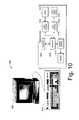
- FIG. 10illustrates an example system in accordance with one embodiment generally at 1000 .
- System 1000includes, in this example, a computing device 1002 and a keyboard unit 1004 .
- Computing device 1002can include any suitable computing device such as a desktop computing device, laptop computer, notebook computer and the like.
- switch 1012is configured to sense when a particular key or keyboard element is depressed.
- a switchis switch closure elements 204 , 206 in FIG. 2 .
- Switch interface 1010notifies microprocessor 1008 when a depression event has occurred.
- Microprocessor 1008controls actuator interface 1014 , which can include the above-mentioned drive electronics, effective to cause the drive electronics to apply a drive voltage(s) to actuator 1016 .
- Actuator interface 1014can be implemented in connection with any suitable hardware, software, firmware, or combination thereof.
- actuator 1016includes both the electrically-deformable material, as well as the physical structure that is mounted to a key or keyboard element.
- the drive electronicscan be used to drive the electrically-deformable material in any suitable way to achieve any suitable movement.
- the drive electronicsare utilized to drive the electrically-deformable material in a manner that imparts multi-vectored movement to the material and hence, to the key or keyboard element with which it is associated.
- this multi-vectored movementcomprises a first movement in a first direction, and then a second movement in a second different direction.
- other movements and various other directionscan be used without departing from the spirit and scope of the claimed subject matter.
- multiple keys or keyboard elementscan be grouped together into a logical grouping which is driven in a multi-vectored manner to provide haptic feedback to a user.
- each logical groupingconstitutes a plate which is moved under the influence of the electrically-deformable material.
- a keyboardcan have single keys or keyboard elements that are driven under the influence of the electrically-deformable material, as well as logical groupings of keys or keyboard elements that are driven under the influence of the electrically-deformable material.
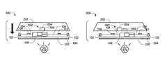
- FIG. 11There, an example keyboard, in accordance with one or more embodiments, is shown generally at 1100 .
- a keyboard housing 1101contains or otherwise supports a plurality of keys. Some of the individual keys are grouped into two logical groupings 1102 , 1104 . These logical groupings define plates that are each moved in a multi-vectored manner as described above.
- a plate 1106includes the space bar key and is separately driven by its own actuator.
- the individual logical groupingsare represented both superimposed on the illustrated keyboard and separately underneath the keyboard. It is to be appreciated and understood that in at least some embodiments, when individual keys or key groupings are moved, the overall housing that supports the keys is not moved. Effectively then, the systems described above can, in at least some embodiments, provide for discrete individual movement of keys or key groupings without moving the corresponding housing.
- any suitable grouping of keys or keyboard elementscan be used.
- the logical grouping of keyscorresponds to those keys that are typically used by the right hand, and those keys that are typically used by the left hand.
- other logical key groupingscan be used without departing from the spirit and scope of the claimed subject matter.
- Step 1200presses a key or keyboard element. This step is typically performed by a user.
- Step 1202detects an associated switch closure.
- a switch associated with a depressed keyis utilized to ascertain when the key has been depressed.
- One specific example of how this can be doneis provided above. Of course, other ways of sensing or detecting a switch closure can be used without departing from the spirit and scope of the claimed subject matter.
- step 1204activates a first drive line for the associated key or key board element.
- the drive lineis connected to an electrically-deformable material as described above. Activating the first drive line causes the electrically-deformable material to deform and hence, move the associated key in a first direction.
- Step 1206activates a second drive line for the associated key or keyboard element. Again, this drive line is connected to the electrically-deformable material as described above. Activating the second drive line causes the electrically-deformable material to deform and hence, move the associated key in a second different direction.
- the first and second directionsare generally opposite of one another.
- form factors of the switch, EAP and keytopcan be designed as follows. It is to be appreciated and understood that the described form factors constitutes examples of one embodiment. As such, other form factors can be used without departing from the spirit and scope of the claimed subject matter.
- the described form factorsrefer to the vertical thickness of the identified elements, for example, as viewed in FIG. 2 .
- keyboardsthat utilize an electrically-deformable material as an actuating mechanism to provide haptic feedback to a user of the keyboard.
- the electrically-deformable materialis utilized to impart, to a depressed key or keyboard element, a multi-vectored movement that produces a perceived acceleration of the key or keyboard element thus providing a user with haptic feedback which simulates a snapover movement.
- the electrically-deformable materialis driven with a voltage responsive to a user depressing a key or keyboard element.
- switch closureis first attained followed by the haptic feedback provided through the multi-vectored movement of the key or keyboard element.
- the multi-vectored movementmoves the key or keyboard element in at least a first direction, and then a second direction which is different from the first.
- Each of the directional movementsis induced by its own driven voltage which is applied to different areas of the electrically-deformable material.
- one of the directions of movementmoves the key or keyboard element a distance which is greater than another of the directions of movement.
- multiple keys or keyboard elementscan be grouped together into a logical grouping which is driven in a multi-vectored movement to provide haptic feedback.
- each logical groupingconstitutes a plate which is moved under the influence of the electrically-deformable material.
- a keyboardcan have single keys or keyboard elements that are driven under the influence of the electrically-deformable material, as well as logical groupings of keys or keyboard elements that are driven under the influence of the electrically-deformable material.
- the electrically-deformable materialcomprises an electroactive polymer or EAP.
- EAPelectroactive polymer
- Other electrically-deformable materialscan, of course, be used.
Landscapes
- Engineering & Computer Science (AREA)
- General Engineering & Computer Science (AREA)
- Theoretical Computer Science (AREA)
- Human Computer Interaction (AREA)
- Physics & Mathematics (AREA)
- General Physics & Mathematics (AREA)
- Input From Keyboards Or The Like (AREA)
- Push-Button Switches (AREA)
Abstract
Description
| Range (between | Implementation | |||
| Upper (about) | about) | (about) | ||
| Switch | .50 mm | .0508 mm .50 mm | .2286 mm |
| EAP | 2.00 mm | .0175 mm-2.00 mm | 1.00 mm |
| Keytop | 1.50 mm | .254 mm-1.50 mm | .508 mm |
| Totals | 4.00 mm | .3223 mm-4.00 mm | 1.7366 mm |
Claims (18)
Priority Applications (1)
| Application Number | Priority Date | Filing Date | Title |
|---|---|---|---|
| US13/458,746US8599047B2 (en) | 2007-07-06 | 2012-04-27 | Haptic keyboard assemblies and methods |
Applications Claiming Priority (4)
| Application Number | Priority Date | Filing Date | Title |
|---|---|---|---|
| US94837707P | 2007-07-06 | 2007-07-06 | |
| US11/945,879US7741979B2 (en) | 2007-07-06 | 2007-11-27 | Haptic keyboard systems and methods |
| US12/791,630US8248278B2 (en) | 2007-07-06 | 2010-06-01 | Haptic keyboard assemblies, systems and methods |
| US13/458,746US8599047B2 (en) | 2007-07-06 | 2012-04-27 | Haptic keyboard assemblies and methods |
Related Parent Applications (1)
| Application Number | Title | Priority Date | Filing Date |
|---|---|---|---|
| US12/791,630ContinuationUS8248278B2 (en) | 2007-07-06 | 2010-06-01 | Haptic keyboard assemblies, systems and methods |
Publications (2)
| Publication Number | Publication Date |
|---|---|
| US20130180839A1 US20130180839A1 (en) | 2013-07-18 |
| US8599047B2true US8599047B2 (en) | 2013-12-03 |
Family
ID=40220434
Family Applications (3)
| Application Number | Title | Priority Date | Filing Date |
|---|---|---|---|
| US11/945,879ActiveUS7741979B2 (en) | 2007-07-06 | 2007-11-27 | Haptic keyboard systems and methods |
| US12/791,630ActiveUS8248278B2 (en) | 2007-07-06 | 2010-06-01 | Haptic keyboard assemblies, systems and methods |
| US13/458,746ActiveUS8599047B2 (en) | 2007-07-06 | 2012-04-27 | Haptic keyboard assemblies and methods |
Family Applications Before (2)
| Application Number | Title | Priority Date | Filing Date |
|---|---|---|---|
| US11/945,879ActiveUS7741979B2 (en) | 2007-07-06 | 2007-11-27 | Haptic keyboard systems and methods |
| US12/791,630ActiveUS8248278B2 (en) | 2007-07-06 | 2010-06-01 | Haptic keyboard assemblies, systems and methods |
Country Status (1)
| Country | Link |
|---|---|
| US (3) | US7741979B2 (en) |
Cited By (28)
| Publication number | Priority date | Publication date | Assignee | Title |
|---|---|---|---|---|
| US20120127071A1 (en)* | 2010-11-18 | 2012-05-24 | Google Inc. | Haptic Feedback to Abnormal Computing Events |
| US9501912B1 (en) | 2014-01-27 | 2016-11-22 | Apple Inc. | Haptic feedback device with a rotating mass of variable eccentricity |
| US9564029B2 (en) | 2014-09-02 | 2017-02-07 | Apple Inc. | Haptic notifications |
| US9608506B2 (en) | 2014-06-03 | 2017-03-28 | Apple Inc. | Linear actuator |
| US9640048B2 (en) | 2009-09-30 | 2017-05-02 | Apple Inc. | Self adapting haptic device |
| US9652040B2 (en) | 2013-08-08 | 2017-05-16 | Apple Inc. | Sculpted waveforms with no or reduced unforced response |
| US9779592B1 (en) | 2013-09-26 | 2017-10-03 | Apple Inc. | Geared haptic feedback element |
| US9886093B2 (en) | 2013-09-27 | 2018-02-06 | Apple Inc. | Band with haptic actuators |
| US9928950B2 (en) | 2013-09-27 | 2018-03-27 | Apple Inc. | Polarized magnetic actuators for haptic response |
| US9997306B2 (en) | 2012-09-28 | 2018-06-12 | Apple Inc. | Ultra low travel keyboard |
| US10013058B2 (en) | 2010-09-21 | 2018-07-03 | Apple Inc. | Touch-based user interface with haptic feedback |
| US10039080B2 (en) | 2016-03-04 | 2018-07-31 | Apple Inc. | Situationally-aware alerts |
| US10120446B2 (en) | 2010-11-19 | 2018-11-06 | Apple Inc. | Haptic input device |
| US10126817B2 (en) | 2013-09-29 | 2018-11-13 | Apple Inc. | Devices and methods for creating haptic effects |
| US10236760B2 (en) | 2013-09-30 | 2019-03-19 | Apple Inc. | Magnetic actuators for haptic response |
| US10268272B2 (en) | 2016-03-31 | 2019-04-23 | Apple Inc. | Dampening mechanical modes of a haptic actuator using a delay |
| US10276001B2 (en) | 2013-12-10 | 2019-04-30 | Apple Inc. | Band attachment mechanism with haptic response |
| US10353467B2 (en) | 2015-03-06 | 2019-07-16 | Apple Inc. | Calibration of haptic devices |
| US10459521B2 (en) | 2013-10-22 | 2019-10-29 | Apple Inc. | Touch surface for simulating materials |
| US10481691B2 (en) | 2015-04-17 | 2019-11-19 | Apple Inc. | Contracting and elongating materials for providing input and output for an electronic device |
| US10545604B2 (en) | 2014-04-21 | 2020-01-28 | Apple Inc. | Apportionment of forces for multi-touch input devices of electronic devices |
| US10566888B2 (en) | 2015-09-08 | 2020-02-18 | Apple Inc. | Linear actuators for use in electronic devices |
| US10599223B1 (en) | 2018-09-28 | 2020-03-24 | Apple Inc. | Button providing force sensing and/or haptic output |
| US10622538B2 (en) | 2017-07-18 | 2020-04-14 | Apple Inc. | Techniques for providing a haptic output and sensing a haptic input using a piezoelectric body |
| US10691211B2 (en) | 2018-09-28 | 2020-06-23 | Apple Inc. | Button providing force sensing and/or haptic output |
| US11380470B2 (en) | 2019-09-24 | 2022-07-05 | Apple Inc. | Methods to control force in reluctance actuators based on flux related parameters |
| US11809631B2 (en) | 2021-09-21 | 2023-11-07 | Apple Inc. | Reluctance haptic engine for an electronic device |
| US11977683B2 (en) | 2021-03-12 | 2024-05-07 | Apple Inc. | Modular systems configured to provide localized haptic feedback using inertial actuators |
Families Citing this family (68)
| Publication number | Priority date | Publication date | Assignee | Title |
|---|---|---|---|---|
| US8248277B2 (en)* | 2007-07-06 | 2012-08-21 | Pacinian Corporation | Haptic keyboard systems and methods |
| US7741979B2 (en)* | 2007-07-06 | 2010-06-22 | Pacinian Corporation | Haptic keyboard systems and methods |
| US8199033B2 (en)* | 2007-07-06 | 2012-06-12 | Pacinian Corporation | Haptic keyboard systems and methods |
| US8310444B2 (en)* | 2008-01-29 | 2012-11-13 | Pacinian Corporation | Projected field haptic actuation |
| WO2009102992A1 (en)* | 2008-02-15 | 2009-08-20 | Pacinian Corporation | Keyboard adaptive haptic response |
| US8203531B2 (en)* | 2008-03-14 | 2012-06-19 | Pacinian Corporation | Vector-specific haptic feedback |
| US20100089735A1 (en)* | 2008-04-17 | 2010-04-15 | Minebea Co., Ltd. | Haptic keyboard apparatus and method |
| US20090303175A1 (en)* | 2008-06-05 | 2009-12-10 | Nokia Corporation | Haptic user interface |
| US20090313020A1 (en)* | 2008-06-12 | 2009-12-17 | Nokia Corporation | Text-to-speech user interface control |
| US9246487B2 (en)* | 2008-12-16 | 2016-01-26 | Dell Products Lp | Keyboard with user configurable granularity scales for pressure sensitive keys |
| US8760273B2 (en)* | 2008-12-16 | 2014-06-24 | Dell Products, Lp | Apparatus and methods for mounting haptics actuation circuitry in keyboards |
| US8711011B2 (en) | 2008-12-16 | 2014-04-29 | Dell Products, Lp | Systems and methods for implementing pressure sensitive keyboards |
| US8674941B2 (en) | 2008-12-16 | 2014-03-18 | Dell Products, Lp | Systems and methods for implementing haptics for pressure sensitive keyboards |
| US8760413B2 (en) | 2009-01-08 | 2014-06-24 | Synaptics Incorporated | Tactile surface |
| MX2011007670A (en)* | 2009-01-21 | 2011-08-08 | Bayer Materialscience Ag | Electroactive polymer transducers for tactile feedback devices. |
| TW201104498A (en)* | 2009-03-10 | 2011-02-01 | Artificial Muscle Inc | Electroactive polymer transducers for tactile feedback devices |
| WO2010129892A2 (en)* | 2009-05-07 | 2010-11-11 | Immersion Corporation | Method and apparatus for providing a haptic feedback shape-changing display |
| US8803798B2 (en)* | 2009-05-07 | 2014-08-12 | Immersion Corporation | System and method for shape deformation and force display of devices |
| US10068728B2 (en) | 2009-10-15 | 2018-09-04 | Synaptics Incorporated | Touchpad with capacitive force sensing |
| US8624839B2 (en) | 2009-10-15 | 2014-01-07 | Synaptics Incorporated | Support-surface apparatus to impart tactile feedback |
| US8552997B2 (en) | 2010-04-23 | 2013-10-08 | Blackberry Limited | Portable electronic device including tactile touch-sensitive input device |
| US9715275B2 (en) | 2010-04-26 | 2017-07-25 | Nokia Technologies Oy | Apparatus, method, computer program and user interface |
| US9791928B2 (en) | 2010-04-26 | 2017-10-17 | Nokia Technologies Oy | Apparatus, method, computer program and user interface |
| US9733705B2 (en) | 2010-04-26 | 2017-08-15 | Nokia Technologies Oy | Apparatus, method, computer program and user interface |
| JP5760393B2 (en)* | 2010-07-15 | 2015-08-12 | ヤマハ株式会社 | Operation detection device |
| TWM395866U (en)* | 2010-08-25 | 2011-01-01 | Li-Yin Ho | Fixing structure for input device |
| US8780060B2 (en) | 2010-11-02 | 2014-07-15 | Apple Inc. | Methods and systems for providing haptic control |
| US20120161949A1 (en)* | 2010-12-28 | 2012-06-28 | Stmicroelectronics Asia Pacific Pte Ltd. | Acuator systems and methods using an electrically deformable material |
| US8847890B2 (en) | 2011-01-04 | 2014-09-30 | Synaptics Incorporated | Leveled touchsurface with planar translational responsiveness to vertical travel |
| US8309870B2 (en)* | 2011-01-04 | 2012-11-13 | Cody George Peterson | Leveled touchsurface with planar translational responsiveness to vertical travel |
| US8912458B2 (en) | 2011-01-04 | 2014-12-16 | Synaptics Incorporated | Touchsurface with level and planar translational travel responsiveness |
| US8717152B2 (en) | 2011-02-11 | 2014-05-06 | Immersion Corporation | Sound to haptic effect conversion system using waveform |
| US8735755B2 (en) | 2011-03-07 | 2014-05-27 | Synaptics Incorporated | Capacitive keyswitch technologies |
| US8748767B2 (en) | 2011-05-27 | 2014-06-10 | Dell Products Lp | Sub-membrane keycap indicator |
| US8700829B2 (en) | 2011-09-14 | 2014-04-15 | Dell Products, Lp | Systems and methods for implementing a multi-function mode for pressure sensitive sensors and keyboards |
| US8830174B1 (en)* | 2011-09-28 | 2014-09-09 | Amazon Technologies, Inc. | Variable profile input button |
| WO2014025786A1 (en) | 2012-08-06 | 2014-02-13 | Synaptics Incorporated | Touchsurface assembly utilizing magnetically enabled hinge |
| US9040851B2 (en) | 2012-08-06 | 2015-05-26 | Synaptics Incorporated | Keycap assembly with an interactive spring mechanism |
| US9177733B2 (en) | 2012-08-06 | 2015-11-03 | Synaptics Incorporated | Touchsurface assemblies with linkages |
| US9218927B2 (en) | 2012-08-06 | 2015-12-22 | Synaptics Incorporated | Touchsurface assembly with level and planar translational responsiveness via a buckling elastic component |
| US9202350B2 (en) | 2012-12-19 | 2015-12-01 | Nokia Technologies Oy | User interfaces and associated methods |
| US9384919B2 (en) | 2013-03-14 | 2016-07-05 | Synaptics Incorporated | Touchsurface assembly having key guides formed in a sheet metal component |
| KR20140122433A (en)* | 2013-04-10 | 2014-10-20 | 삼성디스플레이 주식회사 | Mobile device and method of shape change a mobile device |
| US9213372B2 (en) | 2013-04-19 | 2015-12-15 | Synaptics Incorporated | Retractable keyboard keys |
| US9368300B2 (en) | 2013-08-29 | 2016-06-14 | Dell Products Lp | Systems and methods for lighting spring loaded mechanical key switches |
| US9343248B2 (en) | 2013-08-29 | 2016-05-17 | Dell Products Lp | Systems and methods for implementing spring loaded mechanical key switches with variable displacement sensing |
| US9111005B1 (en) | 2014-03-13 | 2015-08-18 | Dell Products Lp | Systems and methods for configuring and controlling variable pressure and variable displacement sensor operations for information handling systems |
| US9849379B2 (en) | 2015-11-25 | 2017-12-26 | Immersion Corporation | Haptic peripheral having a deformable substrate configured for amplified deformation |
| US9841818B2 (en) | 2015-12-21 | 2017-12-12 | Immersion Corporation | Haptic peripheral having a plurality of deformable membranes and a motor to move radial pins |
| JP6770590B2 (en)* | 2016-06-14 | 2020-10-14 | コーニンクレッカ フィリップス エヌ ヴェKoninklijke Philips N.V. | Actuator device and drive method incorporating an electroactive polymer actuator |
| US11394385B1 (en)* | 2016-09-20 | 2022-07-19 | Apple Inc. | Input device having adjustable input mechanisms |
| US10744531B2 (en)* | 2016-09-23 | 2020-08-18 | Apple Inc. | Multi-core, multi-dimension electromagnet |
| US9949390B1 (en)* | 2016-12-22 | 2018-04-17 | Apple Inc. | Electronic device including movable magnet based actuator for deforming a display and related methods |
| US11609655B2 (en)* | 2017-05-24 | 2023-03-21 | Murata Manufacturing Co., Ltd. | Stimulus transmission device |
| EP3419064A1 (en) | 2017-06-23 | 2018-12-26 | Koninklijke Philips N.V. | Device with multiple electroactive material actuator units and actuating method |
| US11662820B2 (en) | 2020-01-08 | 2023-05-30 | Dell Products, Lp | System for a solid-state keyboard and touchpad providing haptic feedback |
| US11093048B1 (en) | 2020-01-31 | 2021-08-17 | Dell Products, Lp | System for modified key actions and haptic feedback for smart typing assist with a solid-state keyboard and touchpad |
| US11067269B1 (en) | 2020-01-31 | 2021-07-20 | Dell Products, Lp | System and method for backlight integration with electrical contact foil in piezoelectric haptic keyboard |
| US10860112B1 (en) | 2020-01-31 | 2020-12-08 | Dell Products, Lp | System for a solid-state keyboard and touchpad with a single sheet cover for providing haptic feedback |
| US11079849B1 (en) | 2020-01-31 | 2021-08-03 | Dell Products, Lp | System for extended key actions and haptic feedback and optimized key layout for a solid-state keyboard and touchpad |
| US11175745B2 (en) | 2020-01-31 | 2021-11-16 | Dell Products, Lp | System and method for application of piezo electric haptic keyboard personal typing profile |
| US11579695B2 (en) | 2020-01-31 | 2023-02-14 | Dell Products, Lp | System and method for generating sound effects on fingertips with piezoelectric actuators of a haptic keyboard |
| US11079816B1 (en) | 2020-01-31 | 2021-08-03 | Dell Products, Lp | System and method for vapor chamber directional heat dissipation for a piezoelectric keyboard assembly |
| US11294469B2 (en) | 2020-01-31 | 2022-04-05 | Dell Products, Lp | System and method for processing user input via a reconfigurable haptic interface assembly for displaying a modified keyboard configuration |
| US11106772B2 (en) | 2020-01-31 | 2021-08-31 | Dell Products, Lp | System and method for continuous user identification via piezo haptic keyboard and touchpad dynamics |
| US11301053B2 (en) | 2020-01-31 | 2022-04-12 | Dell Products, Lp | System for providing haptic feedback across full palm rest in fixed position of information handling system |
| US11106286B2 (en) | 2020-01-31 | 2021-08-31 | Dell Products, Lp | System and method for mood detection via piezo haptic keyboard dynamics |
| US10936073B1 (en) | 2020-01-31 | 2021-03-02 | Dell Products, Lp | System and method for generating high-frequency and mid-frequency audible sound via piezoelectric actuators of a haptic keyboard |
Citations (116)
| Publication number | Priority date | Publication date | Assignee | Title |
|---|---|---|---|---|
| US4200778A (en) | 1977-05-23 | 1980-04-29 | Ing. C. Olivetti & C., S.P.A. | Electric keyboard of snap-contact type |
| US4529849A (en) | 1983-04-08 | 1985-07-16 | Fujitsu Limited | Push-button switch and a keyboard comprising the same |
| US5057657A (en) | 1990-07-23 | 1991-10-15 | Vedran Skulic | Electrical switch actuator mechanism |
| US5149923A (en) | 1991-03-15 | 1992-09-22 | Lucas Duralith Corporation | Backlit tactile keyboard with improved tactile and electrical characteristics |
| US5239152A (en) | 1990-10-30 | 1993-08-24 | Donnelly Corporation | Touch sensor panel with hidden graphic mode |
| US5612692A (en) | 1994-06-03 | 1997-03-18 | Hewlett-Packard Company | Full travel, sealed, fully backlighted keyboard |
| US5676476A (en) | 1995-12-14 | 1997-10-14 | Uke; Alan K. | Method and apparatus for preventing injury to an electronic computer keyboard operator |
| US5729222A (en) | 1993-05-21 | 1998-03-17 | Jerry Iggulden | User-configurable control device |
| DE19704253A1 (en) | 1997-02-05 | 1998-08-06 | Hella Kg Hueck & Co | Operating unit for motor vehicle component |
| US5943233A (en) | 1994-12-26 | 1999-08-24 | Sharp Kabushiki Kaisha | Input device for a computer and the like and input processing method |
| US6003390A (en) | 1996-07-17 | 1999-12-21 | Legrand | Tactile sensor, in particular for electrical equipment |
| US6218966B1 (en) | 1998-11-05 | 2001-04-17 | International Business Machines Corporation | Tactile feedback keyboard |
| WO2001091100A1 (en) | 2000-05-24 | 2001-11-29 | Immersion Corporation | Haptic devices using electroactive polymers |
| US6429846B2 (en) | 1998-06-23 | 2002-08-06 | Immersion Corporation | Haptic feedback for touchpads and other touch controls |
| US20020149561A1 (en) | 2000-08-08 | 2002-10-17 | Masaaki Fukumoto | Electronic apparatus vibration generator, vibratory informing method and method for controlling information |
| DE10126670A1 (en) | 2001-06-01 | 2002-12-05 | Bayerische Motoren Werke Ag | Electric circuit switch for a motor vehicle comprises vibration or audible signal from piezoelectric element used in touch-pad to generate operating signal |
| US20030208324A1 (en) | 2002-05-02 | 2003-11-06 | International Business Machines Corporation | Pressure sensitive keyboard |
| US20030209131A1 (en) | 2002-05-08 | 2003-11-13 | Yamaha Corporation | Musical instrument |
| US20040031673A1 (en) | 2002-05-23 | 2004-02-19 | Levy David H. | Keypads and key switches |
| US20040085716A1 (en) | 2002-11-05 | 2004-05-06 | Uke Alan K. | Modular keyboard system |
| US20040130526A1 (en) | 1999-12-07 | 2004-07-08 | Rosenberg Louis B. | Haptic feedback using a keyboard device |
| US6791480B1 (en) | 1998-12-04 | 2004-09-14 | Alan K. Uke | Method of preventing and/or alleviating repetitive use injury to electronic computer keyboard operator |
| US20040252104A1 (en) | 2003-06-10 | 2004-12-16 | Fujitsu Component Limited | Inputting device stimulating tactile sense of operator thereof |
| US20050017947A1 (en) | 2000-01-19 | 2005-01-27 | Shahoian Erik J. | Haptic input devices |
| US20050029437A1 (en)* | 2003-08-08 | 2005-02-10 | Akira Hasegawa | Capsule optical sensor |
| DE202005002417U1 (en) | 2005-02-14 | 2005-04-07 | Loewe Opta Gmbh | Operating panel or remote control for a home entertainment system has key fields that are both back-lit and project above surrounding keys to make them easy to detect |
| US20050134561A1 (en) | 2003-12-22 | 2005-06-23 | Tierling Kollin M. | System and method for mapping instructions associated with haptic feedback |
| US20050157893A1 (en) | 2003-09-03 | 2005-07-21 | Sri International, A California Corporation | Surface deformation electroactive polymer transducers |
| US20050184959A1 (en)* | 2004-01-20 | 2005-08-25 | Ralf Kompe | Haptic key controlled data input |
| US20050204906A1 (en) | 2004-03-19 | 2005-09-22 | Gerhard Lengeling | Method and apparatus for simulating a mechanical keyboard action in an electronic keyboard |
| US20050237309A1 (en) | 2004-04-26 | 2005-10-27 | Manish Sharma | Input device including a layer of particles |
| US20060146036A1 (en)* | 2004-12-30 | 2006-07-06 | Michael Prados | Input device |
| US20060187201A1 (en) | 1995-12-01 | 2006-08-24 | Rosenberg Louis B | Method and apparatus for designing force sensations in force feedback computer applications |
| US20060256075A1 (en) | 2005-05-12 | 2006-11-16 | Immersion Corporation | Method and apparatus for providing haptic effects to a touch panel |
| US20060261983A1 (en) | 2005-05-16 | 2006-11-23 | Research In Motion Limited | Key system for a communication device |
| US20060279538A1 (en) | 1997-04-25 | 2006-12-14 | Chang Dean C | Design of force sensations for haptic feedback computer interfaces |
| US20060290662A1 (en) | 2005-06-27 | 2006-12-28 | Coactive Drive Corporation | Synchronized vibration device for haptic feedback |
| US7182691B1 (en) | 2000-09-28 | 2007-02-27 | Immersion Corporation | Directional inertial tactile feedback using rotating masses |
| US20070047051A1 (en)* | 2005-08-30 | 2007-03-01 | Uni-Pixel Displays, Inc. | Electromechanical dynamic force profile articulating mechanism |
| US20070065215A1 (en) | 2005-04-18 | 2007-03-22 | Ronald Brown | Display-equipped key,key assembly, device and method |
| US20070091070A1 (en) | 2005-10-20 | 2007-04-26 | Microsoft Corporation | Keyboard with integrated key and touchpad |
| US20070139359A1 (en)* | 2002-02-02 | 2007-06-21 | Oliver Voelckers | Device for inputting text by actuating keys of a numeric keypad for electronic devices and method for processing input impulses during text input |
| US20070152974A1 (en) | 2006-01-03 | 2007-07-05 | Samsung Electronics Co., Ltd. | Haptic button and haptic device using the same |
| US20070193436A1 (en) | 2001-10-10 | 2007-08-23 | Immersion Corporation | System and method for manipulation of sound data using haptic feedback |
| US20070203011A1 (en)* | 2006-02-01 | 2007-08-30 | Gudgel Katherine A | Translucent piezoelectric glass ceramic |
| US20070216643A1 (en)* | 2004-06-16 | 2007-09-20 | Morris Robert P | Multipurpose Navigation Keys For An Electronic Device |
| US20070234890A1 (en) | 2006-03-24 | 2007-10-11 | Masayoshi Yamashita | Key driving apparatus and keyboard musical instrument |
| US20070236449A1 (en) | 2006-04-06 | 2007-10-11 | Immersion Corporation | Systems and Methods for Enhanced Haptic Effects |
| US20070236450A1 (en)* | 2006-03-24 | 2007-10-11 | Northwestern University | Haptic device with indirect haptic feedback |
| US20070234887A1 (en) | 2006-03-24 | 2007-10-11 | Yamaha Corporation | Wind musical instrument with pitch changing mechanism and supporting system for pitch change |
| US20070251810A1 (en) | 2006-02-15 | 2007-11-01 | Logitech, Inc. | Turnable keys for a control device |
| US20070285284A1 (en) | 2006-06-08 | 2007-12-13 | Motorola, Inc | Method and apparatus for keypad manipulation |
| US20080010593A1 (en) | 2006-06-30 | 2008-01-10 | Nokia Corporation | User interface input device |
| US20080042978A1 (en) | 2006-08-18 | 2008-02-21 | Microsoft Corporation | Contact, motion and position sensing circuitry |
| US7342573B2 (en) | 2004-07-07 | 2008-03-11 | Nokia Corporation | Electrostrictive polymer as a combined haptic-seal actuator |
| US20080083314A1 (en) | 2006-09-06 | 2008-04-10 | Yoshinori Hayashi | Key actuating apparatus and key actuation control system |
| US20080084384A1 (en) | 2006-10-05 | 2008-04-10 | Immersion Corporation | Multiple Mode Haptic Feedback System |
| US20080092087A1 (en) | 2005-09-19 | 2008-04-17 | Ronald Brown | Method and Display Data Entry Unit |
| US20080092720A1 (en) | 2006-09-04 | 2008-04-24 | Masayoshi Yamashita | Key actuating system |
| US7364337B2 (en) | 2005-07-12 | 2008-04-29 | Ls Tech Co. Ltd. | Flexible backlight unit for key of input device |
| US20080174889A1 (en)* | 2007-01-19 | 2008-07-24 | Industrial Technology Research Institute | Optical focusing device |
| US20080197901A1 (en) | 2007-02-16 | 2008-08-21 | Immersion Corporation | Multiple Pulse Width Modulation |
| US20080198139A1 (en)* | 2007-02-20 | 2008-08-21 | Immersion Corporation | Haptic Feedback System with Stored Effects |
| US20080223706A1 (en) | 2007-03-15 | 2008-09-18 | Yasuji Hagiwara | Input device |
| US20080251364A1 (en) | 2007-04-11 | 2008-10-16 | Nokia Corporation | Feedback on input actuator |
| US20080303782A1 (en) | 2007-06-05 | 2008-12-11 | Immersion Corporation | Method and apparatus for haptic enabled flexible touch sensitive surface |
| US20090002199A1 (en) | 2007-06-28 | 2009-01-01 | Nokia Corporation | Piezoelectric sensing as user input means |
| US20090002205A1 (en) | 2007-06-28 | 2009-01-01 | Sony Ericsson Mobile Communications Ab | Data input device and portable electronic device |
| US20090007758A1 (en)* | 2007-07-06 | 2009-01-08 | James William Schlosser | Haptic Keyboard Systems and Methods |
| US20090008234A1 (en) | 2007-07-03 | 2009-01-08 | William Haywood Tolbert | Input device and an electronic device comprising an input device |
| US20090072662A1 (en) | 2007-09-17 | 2009-03-19 | Motorola, Inc. | Electronic device and circuit for providing tactile feedback |
| US20090085878A1 (en)* | 2007-09-28 | 2009-04-02 | Immersion Corporation | Multi-Touch Device Having Dynamic Haptic Effects |
| US20090085882A1 (en)* | 2007-10-01 | 2009-04-02 | Immersion Corporation | Directional Haptic Effects For A Handheld Device |
| WO2009043605A1 (en) | 2007-10-01 | 2009-04-09 | Sony Ericsson Mobile Communications Ab | Cellular terminals and other electronic devices and methods using electroactive polymer transducer indicators |
| US20090106655A1 (en)* | 2006-10-04 | 2009-04-23 | Immersion Corporation | Haptic Effects With Proximity Sensing |
| US20090128368A1 (en) | 2004-04-15 | 2009-05-21 | Chao Chen | Split keyboard |
| US20090135142A1 (en)* | 2007-11-27 | 2009-05-28 | Motorola, Inc. | Data entry device and method |
| US20090160763A1 (en)* | 2007-12-21 | 2009-06-25 | Patrick Cauwels | Haptic Response Apparatus for an Electronic Device |
| US20090167704A1 (en)* | 2007-12-31 | 2009-07-02 | Apple Inc. | Multi-touch display screen with localized tactile feedback |
| US20090174672A1 (en)* | 2008-01-03 | 2009-07-09 | Schmidt Robert M | Haptic actuator assembly and method of manufacturing a haptic actuator assembly |
| US20090178913A1 (en)* | 2007-07-06 | 2009-07-16 | Cody George Peterson | Haptic Keyboard Systems and Methods |
| US20090189873A1 (en)* | 2008-01-29 | 2009-07-30 | Cody George Peterson | Projected Field Haptic Actuation |
| US20090189790A1 (en)* | 2007-07-06 | 2009-07-30 | Cody George Peterson | Haptic Keyboard Systems and Methods |
| US20090188374A1 (en) | 2008-01-29 | 2009-07-30 | John Bertil Folkesson | Electronic musical keyboard with tactile feedback |
| US20090210568A1 (en)* | 2008-02-15 | 2009-08-20 | Pacinian Corporation | Keyboard Adaptive Haptic Response |
| US20090219252A1 (en)* | 2008-02-28 | 2009-09-03 | Nokia Corporation | Apparatus, method and computer program product for moving controls on a touchscreen |
| US20090231113A1 (en) | 2004-05-27 | 2009-09-17 | Olien Neil T | Products and Processes For Providing Haptic Feedback In Resistive Interface Devices |
| US20090231277A1 (en)* | 2008-03-14 | 2009-09-17 | Cody George Peterson | Vector-Specific Haptic Feedback |
| US20090231271A1 (en)* | 2008-03-12 | 2009-09-17 | Immersion Corporation | Haptically Enabled User Interface |
| US20090244017A1 (en)* | 2008-03-28 | 2009-10-01 | Denso International America, Inc. | Haptic tracking remote control for driver information center system |
| US20090267920A1 (en)* | 2008-04-24 | 2009-10-29 | Research In Motion Limited | System and method for generating a feedback signal in response to an input signal provided to an electronic device |
| US20090267921A1 (en) | 1995-06-29 | 2009-10-29 | Pryor Timothy R | Programmable tactile touch screen displays and man-machine interfaces for improved vehicle instrumentation and telematics |
| US20090303187A1 (en) | 2005-07-22 | 2009-12-10 | Matt Pallakoff | System and method for a thumb-optimized touch-screen user interface |
| US20090303022A1 (en)* | 2008-06-09 | 2009-12-10 | Research In Motion Limited | System and method for providing tactile feedback to a user of an electronic device |
| US20100045612A1 (en) | 2006-09-09 | 2010-02-25 | Moelne Anders | Integrated pressure sensitive lens assembly |
| US20100108408A1 (en)* | 2007-03-21 | 2010-05-06 | Northwestern University | Haptic device with controlled traction forces |
| US20100128002A1 (en)* | 2008-11-26 | 2010-05-27 | William Stacy | Touch-sensitive display method and apparatus |
| US20100130280A1 (en)* | 2006-10-10 | 2010-05-27 | Wms Gaming, Inc. | Multi-player, multi-touch table for use in wagering game systems |
| US20100160016A1 (en)* | 2006-03-31 | 2010-06-24 | Shimabukuro Jorge L | Portable Wagering Game With Vibrational Cues and Feedback Mechanism |
| US20100156801A1 (en) | 2005-08-13 | 2010-06-24 | Michael Yurochko | Lighting and usability features for key structures and keypads on computing devices |
| US20100171715A1 (en)* | 2009-01-08 | 2010-07-08 | Cody George Peterson | Tactile Surface |
| US20100177050A1 (en) | 2009-01-14 | 2010-07-15 | Immersion Corporation | Method and Apparatus for Generating Haptic Feedback from Plasma Actuation |
| US7834857B2 (en)* | 2005-09-14 | 2010-11-16 | Volkswagen Ag | Input device having a touch panel and haptic feedback |
| US20100295792A1 (en) | 2007-02-23 | 2010-11-25 | Nokia Corporation | Optical actuators in keypads |
| US20100302169A1 (en) | 2009-06-01 | 2010-12-02 | Apple Inc. | Keyboard with increased control of backlit keys |
| US20100314396A1 (en) | 2009-06-15 | 2010-12-16 | Magna Steyr Fahrzeugtechnik Ag & Co. Kg | Pressure vessel for gaseous or liquid media |
| US20110073454A1 (en) | 2009-09-28 | 2011-03-31 | Research In Motion Limited | key assembly for an electronic device having a multi-character keycap |
| US20110094868A1 (en) | 2009-10-26 | 2011-04-28 | Research In Motion Limited | Key assembly for an electronic device having a connected keycap |
| US20110102326A1 (en) | 2008-12-16 | 2011-05-05 | Casparian Mark A | Systems and methods for implementing haptics for pressure sensitive keyboards |
| US20110107958A1 (en) | 2009-11-12 | 2011-05-12 | Apple Inc. | Input devices and methods of operation |
| US20110148607A1 (en) | 2009-12-17 | 2011-06-23 | Charles Timberlake Zeleny | System,device and method for providing haptic technology |
| US7969288B2 (en) | 1997-11-14 | 2011-06-28 | Immersion Corporation | Force feedback system including multi-tasking graphical host environment and interface device |
| US20120020045A1 (en) | 2010-07-21 | 2012-01-26 | Research In Motion Limited | Portable electronic device having a waterproof keypad |
| US20120139843A1 (en) | 1999-09-15 | 2012-06-07 | Michael Shipman | Illuminated keyboard |
| US20120166696A1 (en) | 2009-06-26 | 2012-06-28 | Nokia Corporation | Method, Apparatus and Computer Program Code Handling a User Input |
| US8263887B2 (en) | 2009-02-26 | 2012-09-11 | Research In Motion Limited | Backlit key assembly having a reduced thickness |
Family Cites Families (5)
| Publication number | Priority date | Publication date | Assignee | Title |
|---|---|---|---|---|
| JPS61825A (en) | 1984-06-14 | 1986-01-06 | Matsushita Electric Ind Co Ltd | character input device |
| EP0654727A3 (en) | 1993-11-24 | 1998-07-01 | Microsoft Corporation | Keyboard incorporating pointing and tilting devices |
| EP1548776A1 (en) | 2003-12-22 | 2005-06-29 | Siemens Aktiengesellschaft | A key, keypad, and portable electronic device |
| DE102004005501A1 (en) | 2004-01-30 | 2005-08-18 | Aurenz Gmbh | Data input facility and corresponding control process has movable pins, which serve as input device and form a three-dimensional display |
| DE102005002417A1 (en) | 2005-01-18 | 2006-07-27 | Behr Gmbh & Co. Kg | Heat exchangers, in particular intercoolers or coolant radiators for motor vehicles |
- 2007
- 2007-11-27USUS11/945,879patent/US7741979B2/enactiveActive
- 2010
- 2010-06-01USUS12/791,630patent/US8248278B2/enactiveActive
- 2012
- 2012-04-27USUS13/458,746patent/US8599047B2/enactiveActive
Patent Citations (142)
| Publication number | Priority date | Publication date | Assignee | Title |
|---|---|---|---|---|
| US4200778A (en) | 1977-05-23 | 1980-04-29 | Ing. C. Olivetti & C., S.P.A. | Electric keyboard of snap-contact type |
| US4529849A (en) | 1983-04-08 | 1985-07-16 | Fujitsu Limited | Push-button switch and a keyboard comprising the same |
| US5057657A (en) | 1990-07-23 | 1991-10-15 | Vedran Skulic | Electrical switch actuator mechanism |
| US5239152A (en) | 1990-10-30 | 1993-08-24 | Donnelly Corporation | Touch sensor panel with hidden graphic mode |
| US5149923A (en) | 1991-03-15 | 1992-09-22 | Lucas Duralith Corporation | Backlit tactile keyboard with improved tactile and electrical characteristics |
| US5729222A (en) | 1993-05-21 | 1998-03-17 | Jerry Iggulden | User-configurable control device |
| US5612692A (en) | 1994-06-03 | 1997-03-18 | Hewlett-Packard Company | Full travel, sealed, fully backlighted keyboard |
| US5943233A (en) | 1994-12-26 | 1999-08-24 | Sharp Kabushiki Kaisha | Input device for a computer and the like and input processing method |
| US20090267921A1 (en) | 1995-06-29 | 2009-10-29 | Pryor Timothy R | Programmable tactile touch screen displays and man-machine interfaces for improved vehicle instrumentation and telematics |
| US20060187201A1 (en) | 1995-12-01 | 2006-08-24 | Rosenberg Louis B | Method and apparatus for designing force sensations in force feedback computer applications |
| US5676476A (en) | 1995-12-14 | 1997-10-14 | Uke; Alan K. | Method and apparatus for preventing injury to an electronic computer keyboard operator |
| US6003390A (en) | 1996-07-17 | 1999-12-21 | Legrand | Tactile sensor, in particular for electrical equipment |
| DE19704253A1 (en) | 1997-02-05 | 1998-08-06 | Hella Kg Hueck & Co | Operating unit for motor vehicle component |
| US20060279538A1 (en) | 1997-04-25 | 2006-12-14 | Chang Dean C | Design of force sensations for haptic feedback computer interfaces |
| US7969288B2 (en) | 1997-11-14 | 2011-06-28 | Immersion Corporation | Force feedback system including multi-tasking graphical host environment and interface device |
| US6429846B2 (en) | 1998-06-23 | 2002-08-06 | Immersion Corporation | Haptic feedback for touchpads and other touch controls |
| US8059105B2 (en) | 1998-06-23 | 2011-11-15 | Immersion Corporation | Haptic feedback for touchpads and other touch controls |
| US8031181B2 (en) | 1998-06-23 | 2011-10-04 | Immersion Corporation | Haptic feedback for touchpads and other touch controls |
| US7982720B2 (en) | 1998-06-23 | 2011-07-19 | Immersion Corporation | Haptic feedback for touchpads and other touch controls |
| US7592999B2 (en) | 1998-06-23 | 2009-09-22 | Immersion Corporation | Haptic feedback for touchpads and other touch controls |
| US6218966B1 (en) | 1998-11-05 | 2001-04-17 | International Business Machines Corporation | Tactile feedback keyboard |
| US6791480B1 (en) | 1998-12-04 | 2004-09-14 | Alan K. Uke | Method of preventing and/or alleviating repetitive use injury to electronic computer keyboard operator |
| US20120139843A1 (en) | 1999-09-15 | 2012-06-07 | Michael Shipman | Illuminated keyboard |
| US20060267949A1 (en) | 1999-12-07 | 2006-11-30 | Rosenberg Louis B | Haptic feedback using a keyboard device |
| US20040130526A1 (en) | 1999-12-07 | 2004-07-08 | Rosenberg Louis B. | Haptic feedback using a keyboard device |
| US20080062145A1 (en)* | 2000-01-19 | 2008-03-13 | Immersion Corporation | Haptic interface for touch screen embodiments |
| US20050052430A1 (en)* | 2000-01-19 | 2005-03-10 | Shahoian Erik J. | Haptic interface for laptop computers and other portable devices |
| US20050017947A1 (en) | 2000-01-19 | 2005-01-27 | Shahoian Erik J. | Haptic input devices |
| US20080062144A1 (en)* | 2000-01-19 | 2008-03-13 | Immersion Corporation | Haptic interface for touch screen embodiments |
| US20080060856A1 (en)* | 2000-01-19 | 2008-03-13 | Immersion Corporation | Haptic interface for touch screen embodiments |
| US7196688B2 (en) | 2000-05-24 | 2007-03-27 | Immersion Corporation | Haptic devices using electroactive polymers |
| US7339572B2 (en) | 2000-05-24 | 2008-03-04 | Immersion Corporation | Haptic devices using electroactive polymers |
| WO2001091100A1 (en) | 2000-05-24 | 2001-11-29 | Immersion Corporation | Haptic devices using electroactive polymers |
| US20070146317A1 (en) | 2000-05-24 | 2007-06-28 | Immersion Corporation | Haptic devices using electroactive polymers |
| US20020054060A1 (en) | 2000-05-24 | 2002-05-09 | Schena Bruce M. | Haptic devices using electroactive polymers |
| US20020149561A1 (en) | 2000-08-08 | 2002-10-17 | Masaaki Fukumoto | Electronic apparatus vibration generator, vibratory informing method and method for controlling information |
| US7182691B1 (en) | 2000-09-28 | 2007-02-27 | Immersion Corporation | Directional inertial tactile feedback using rotating masses |
| DE10126670A1 (en) | 2001-06-01 | 2002-12-05 | Bayerische Motoren Werke Ag | Electric circuit switch for a motor vehicle comprises vibration or audible signal from piezoelectric element used in touch-pad to generate operating signal |
| US20070193436A1 (en) | 2001-10-10 | 2007-08-23 | Immersion Corporation | System and method for manipulation of sound data using haptic feedback |
| US20070139359A1 (en)* | 2002-02-02 | 2007-06-21 | Oliver Voelckers | Device for inputting text by actuating keys of a numeric keypad for electronic devices and method for processing input impulses during text input |
| US20030208324A1 (en) | 2002-05-02 | 2003-11-06 | International Business Machines Corporation | Pressure sensitive keyboard |
| US6684166B2 (en) | 2002-05-02 | 2004-01-27 | International Business Machines Corporation | Pressure sensitive keyboard |
| US20030209131A1 (en) | 2002-05-08 | 2003-11-13 | Yamaha Corporation | Musical instrument |
| US20040031673A1 (en) | 2002-05-23 | 2004-02-19 | Levy David H. | Keypads and key switches |
| US20040085716A1 (en) | 2002-11-05 | 2004-05-06 | Uke Alan K. | Modular keyboard system |
| US20040252104A1 (en) | 2003-06-10 | 2004-12-16 | Fujitsu Component Limited | Inputting device stimulating tactile sense of operator thereof |
| US20050029437A1 (en)* | 2003-08-08 | 2005-02-10 | Akira Hasegawa | Capsule optical sensor |
| US20050157893A1 (en) | 2003-09-03 | 2005-07-21 | Sri International, A California Corporation | Surface deformation electroactive polymer transducers |
| US20080289952A1 (en) | 2003-09-03 | 2008-11-27 | Sri International | Surface deformation electroactive polymer transducers |
| US20050134561A1 (en) | 2003-12-22 | 2005-06-23 | Tierling Kollin M. | System and method for mapping instructions associated with haptic feedback |
| US7791588B2 (en) | 2003-12-22 | 2010-09-07 | Immersion Corporation | System and method for mapping instructions associated with haptic feedback |
| US20050184959A1 (en)* | 2004-01-20 | 2005-08-25 | Ralf Kompe | Haptic key controlled data input |
| US20050204906A1 (en) | 2004-03-19 | 2005-09-22 | Gerhard Lengeling | Method and apparatus for simulating a mechanical keyboard action in an electronic keyboard |
| US7166795B2 (en) | 2004-03-19 | 2007-01-23 | Apple Computer, Inc. | Method and apparatus for simulating a mechanical keyboard action in an electronic keyboard |
| US20090128368A1 (en) | 2004-04-15 | 2009-05-21 | Chao Chen | Split keyboard |
| US20050237309A1 (en) | 2004-04-26 | 2005-10-27 | Manish Sharma | Input device including a layer of particles |
| US20090231113A1 (en) | 2004-05-27 | 2009-09-17 | Olien Neil T | Products and Processes For Providing Haptic Feedback In Resistive Interface Devices |
| US20070216643A1 (en)* | 2004-06-16 | 2007-09-20 | Morris Robert P | Multipurpose Navigation Keys For An Electronic Device |
| US7342573B2 (en) | 2004-07-07 | 2008-03-11 | Nokia Corporation | Electrostrictive polymer as a combined haptic-seal actuator |
| US20060146036A1 (en)* | 2004-12-30 | 2006-07-06 | Michael Prados | Input device |
| DE202005002417U1 (en) | 2005-02-14 | 2005-04-07 | Loewe Opta Gmbh | Operating panel or remote control for a home entertainment system has key fields that are both back-lit and project above surrounding keys to make them easy to detect |
| US20070065215A1 (en) | 2005-04-18 | 2007-03-22 | Ronald Brown | Display-equipped key,key assembly, device and method |
| US20060256075A1 (en) | 2005-05-12 | 2006-11-16 | Immersion Corporation | Method and apparatus for providing haptic effects to a touch panel |
| US20060261983A1 (en) | 2005-05-16 | 2006-11-23 | Research In Motion Limited | Key system for a communication device |
| US20060290662A1 (en) | 2005-06-27 | 2006-12-28 | Coactive Drive Corporation | Synchronized vibration device for haptic feedback |
| US7364337B2 (en) | 2005-07-12 | 2008-04-29 | Ls Tech Co. Ltd. | Flexible backlight unit for key of input device |
| US20090303187A1 (en) | 2005-07-22 | 2009-12-10 | Matt Pallakoff | System and method for a thumb-optimized touch-screen user interface |
| US20100156801A1 (en) | 2005-08-13 | 2010-06-24 | Michael Yurochko | Lighting and usability features for key structures and keypads on computing devices |
| US20080158637A1 (en)* | 2005-08-30 | 2008-07-03 | Unipixel Displays, Inc. | Electromechanical dynamic force profile articulating mechanism |
| US20070047051A1 (en)* | 2005-08-30 | 2007-03-01 | Uni-Pixel Displays, Inc. | Electromechanical dynamic force profile articulating mechanism |
| US20080212158A1 (en)* | 2005-08-30 | 2008-09-04 | Unipixel Displays, Inc. | Electromechanical dynamic force profile articulating mechanism |
| US7834857B2 (en)* | 2005-09-14 | 2010-11-16 | Volkswagen Ag | Input device having a touch panel and haptic feedback |
| US20080092087A1 (en) | 2005-09-19 | 2008-04-17 | Ronald Brown | Method and Display Data Entry Unit |
| US20070091070A1 (en) | 2005-10-20 | 2007-04-26 | Microsoft Corporation | Keyboard with integrated key and touchpad |
| US20070152974A1 (en) | 2006-01-03 | 2007-07-05 | Samsung Electronics Co., Ltd. | Haptic button and haptic device using the same |
| US20070203011A1 (en)* | 2006-02-01 | 2007-08-30 | Gudgel Katherine A | Translucent piezoelectric glass ceramic |
| US20070251810A1 (en) | 2006-02-15 | 2007-11-01 | Logitech, Inc. | Turnable keys for a control device |
| US20070236450A1 (en)* | 2006-03-24 | 2007-10-11 | Northwestern University | Haptic device with indirect haptic feedback |
| US20070234890A1 (en) | 2006-03-24 | 2007-10-11 | Masayoshi Yamashita | Key driving apparatus and keyboard musical instrument |
| US20070234887A1 (en) | 2006-03-24 | 2007-10-11 | Yamaha Corporation | Wind musical instrument with pitch changing mechanism and supporting system for pitch change |
| US20100160016A1 (en)* | 2006-03-31 | 2010-06-24 | Shimabukuro Jorge L | Portable Wagering Game With Vibrational Cues and Feedback Mechanism |
| US20070236449A1 (en) | 2006-04-06 | 2007-10-11 | Immersion Corporation | Systems and Methods for Enhanced Haptic Effects |
| US20070285284A1 (en) | 2006-06-08 | 2007-12-13 | Motorola, Inc | Method and apparatus for keypad manipulation |
| US20080010593A1 (en) | 2006-06-30 | 2008-01-10 | Nokia Corporation | User interface input device |
| US20080042978A1 (en) | 2006-08-18 | 2008-02-21 | Microsoft Corporation | Contact, motion and position sensing circuitry |
| US20080092720A1 (en) | 2006-09-04 | 2008-04-24 | Masayoshi Yamashita | Key actuating system |
| US20080083314A1 (en) | 2006-09-06 | 2008-04-10 | Yoshinori Hayashi | Key actuating apparatus and key actuation control system |
| US20100045612A1 (en) | 2006-09-09 | 2010-02-25 | Moelne Anders | Integrated pressure sensitive lens assembly |
| US20090106655A1 (en)* | 2006-10-04 | 2009-04-23 | Immersion Corporation | Haptic Effects With Proximity Sensing |
| US20080084384A1 (en) | 2006-10-05 | 2008-04-10 | Immersion Corporation | Multiple Mode Haptic Feedback System |
| US20100130280A1 (en)* | 2006-10-10 | 2010-05-27 | Wms Gaming, Inc. | Multi-player, multi-touch table for use in wagering game systems |
| US20080174889A1 (en)* | 2007-01-19 | 2008-07-24 | Industrial Technology Research Institute | Optical focusing device |
| US20080197901A1 (en) | 2007-02-16 | 2008-08-21 | Immersion Corporation | Multiple Pulse Width Modulation |
| US20080198139A1 (en)* | 2007-02-20 | 2008-08-21 | Immersion Corporation | Haptic Feedback System with Stored Effects |
| US20100295792A1 (en) | 2007-02-23 | 2010-11-25 | Nokia Corporation | Optical actuators in keypads |
| US20080223706A1 (en) | 2007-03-15 | 2008-09-18 | Yasuji Hagiwara | Input device |
| US20100108408A1 (en)* | 2007-03-21 | 2010-05-06 | Northwestern University | Haptic device with controlled traction forces |
| US20080251364A1 (en) | 2007-04-11 | 2008-10-16 | Nokia Corporation | Feedback on input actuator |
| US20080303782A1 (en) | 2007-06-05 | 2008-12-11 | Immersion Corporation | Method and apparatus for haptic enabled flexible touch sensitive surface |
| US20090002205A1 (en) | 2007-06-28 | 2009-01-01 | Sony Ericsson Mobile Communications Ab | Data input device and portable electronic device |
| US20090002199A1 (en) | 2007-06-28 | 2009-01-01 | Nokia Corporation | Piezoelectric sensing as user input means |
| US20090008234A1 (en) | 2007-07-03 | 2009-01-08 | William Haywood Tolbert | Input device and an electronic device comprising an input device |
| US20090007758A1 (en)* | 2007-07-06 | 2009-01-08 | James William Schlosser | Haptic Keyboard Systems and Methods |
| US8248278B2 (en) | 2007-07-06 | 2012-08-21 | Pacinian Corporation | Haptic keyboard assemblies, systems and methods |
| US8199033B2 (en) | 2007-07-06 | 2012-06-12 | Pacinian Corporation | Haptic keyboard systems and methods |
| US20110227763A1 (en) | 2007-07-06 | 2011-09-22 | James William Schlosser | Haptic Keyboard Assemblies, Systems and Methods |
| US8248277B2 (en) | 2007-07-06 | 2012-08-21 | Pacinian Corporation | Haptic keyboard systems and methods |
| US20090178913A1 (en)* | 2007-07-06 | 2009-07-16 | Cody George Peterson | Haptic Keyboard Systems and Methods |
| US7741979B2 (en) | 2007-07-06 | 2010-06-22 | Pacinian Corporation | Haptic keyboard systems and methods |
| US20090189790A1 (en)* | 2007-07-06 | 2009-07-30 | Cody George Peterson | Haptic Keyboard Systems and Methods |
| US20090072662A1 (en) | 2007-09-17 | 2009-03-19 | Motorola, Inc. | Electronic device and circuit for providing tactile feedback |
| US20090085878A1 (en)* | 2007-09-28 | 2009-04-02 | Immersion Corporation | Multi-Touch Device Having Dynamic Haptic Effects |
| WO2009043605A1 (en) | 2007-10-01 | 2009-04-09 | Sony Ericsson Mobile Communications Ab | Cellular terminals and other electronic devices and methods using electroactive polymer transducer indicators |
| US20090085882A1 (en)* | 2007-10-01 | 2009-04-02 | Immersion Corporation | Directional Haptic Effects For A Handheld Device |
| US20090135142A1 (en)* | 2007-11-27 | 2009-05-28 | Motorola, Inc. | Data entry device and method |
| US20090160763A1 (en)* | 2007-12-21 | 2009-06-25 | Patrick Cauwels | Haptic Response Apparatus for an Electronic Device |
| US20090167704A1 (en)* | 2007-12-31 | 2009-07-02 | Apple Inc. | Multi-touch display screen with localized tactile feedback |
| US20090174672A1 (en)* | 2008-01-03 | 2009-07-09 | Schmidt Robert M | Haptic actuator assembly and method of manufacturing a haptic actuator assembly |
| WO2009097358A1 (en) | 2008-01-29 | 2009-08-06 | Pacinian Corporation | Touch input device with haptic feedback |
| US20090189873A1 (en)* | 2008-01-29 | 2009-07-30 | Cody George Peterson | Projected Field Haptic Actuation |
| US20090188374A1 (en) | 2008-01-29 | 2009-07-30 | John Bertil Folkesson | Electronic musical keyboard with tactile feedback |
| US20090210568A1 (en)* | 2008-02-15 | 2009-08-20 | Pacinian Corporation | Keyboard Adaptive Haptic Response |
| US20090219252A1 (en)* | 2008-02-28 | 2009-09-03 | Nokia Corporation | Apparatus, method and computer program product for moving controls on a touchscreen |
| US20090231271A1 (en)* | 2008-03-12 | 2009-09-17 | Immersion Corporation | Haptically Enabled User Interface |
| US8203531B2 (en) | 2008-03-14 | 2012-06-19 | Pacinian Corporation | Vector-specific haptic feedback |
| US20090231277A1 (en)* | 2008-03-14 | 2009-09-17 | Cody George Peterson | Vector-Specific Haptic Feedback |
| US20090244017A1 (en)* | 2008-03-28 | 2009-10-01 | Denso International America, Inc. | Haptic tracking remote control for driver information center system |
| US20090267920A1 (en)* | 2008-04-24 | 2009-10-29 | Research In Motion Limited | System and method for generating a feedback signal in response to an input signal provided to an electronic device |
| US20090303022A1 (en)* | 2008-06-09 | 2009-12-10 | Research In Motion Limited | System and method for providing tactile feedback to a user of an electronic device |
| US20100128002A1 (en)* | 2008-11-26 | 2010-05-27 | William Stacy | Touch-sensitive display method and apparatus |
| US20110102326A1 (en) | 2008-12-16 | 2011-05-05 | Casparian Mark A | Systems and methods for implementing haptics for pressure sensitive keyboards |
| US20100171715A1 (en)* | 2009-01-08 | 2010-07-08 | Cody George Peterson | Tactile Surface |
| US20100177050A1 (en) | 2009-01-14 | 2010-07-15 | Immersion Corporation | Method and Apparatus for Generating Haptic Feedback from Plasma Actuation |
| US8263887B2 (en) | 2009-02-26 | 2012-09-11 | Research In Motion Limited | Backlit key assembly having a reduced thickness |
| US20100302169A1 (en) | 2009-06-01 | 2010-12-02 | Apple Inc. | Keyboard with increased control of backlit keys |
| US20100314396A1 (en) | 2009-06-15 | 2010-12-16 | Magna Steyr Fahrzeugtechnik Ag & Co. Kg | Pressure vessel for gaseous or liquid media |
| US20120166696A1 (en) | 2009-06-26 | 2012-06-28 | Nokia Corporation | Method, Apparatus and Computer Program Code Handling a User Input |
| US20110073454A1 (en) | 2009-09-28 | 2011-03-31 | Research In Motion Limited | key assembly for an electronic device having a multi-character keycap |
| US20110094868A1 (en) | 2009-10-26 | 2011-04-28 | Research In Motion Limited | Key assembly for an electronic device having a connected keycap |
| US20110107958A1 (en) | 2009-11-12 | 2011-05-12 | Apple Inc. | Input devices and methods of operation |
| US20110148607A1 (en) | 2009-12-17 | 2011-06-23 | Charles Timberlake Zeleny | System,device and method for providing haptic technology |
| US20120020045A1 (en) | 2010-07-21 | 2012-01-26 | Research In Motion Limited | Portable electronic device having a waterproof keypad |
Non-Patent Citations (91)
| Title |
|---|
| "Elastomers: Powerful Polymer", Retrieved from , (Jun. 2006),5 pages. |
| "Elastomers: Powerful Polymer", Retrieved from <http://appliancedesign.com/copyright/>, (Jun. 2006),5 pages. |
| "Final Office Action mailed Nov. 22, 2011", U.S. Appl. No. 12/371,301, 6 pages. |
| "Final Office Action mailed Nov. 8, 2011", U.S. Appl. No. 12/360,265, 11 pages. |
| "Haptic Touch Technology", Pacinian,(Nov. 2007),2 pages. |
| "Haptics: Learning Through Touch", Retrieved from , (2004),5 pages. |
| "Haptics: Learning Through Touch", Retrieved from <http://ced.ncsu.edu/nanoscale/haptics.htm>, (2004),5 pages. |
| "International Search Report and Written Opinion", Application No. PCT/US2009/032289, (Dec. 23, 2009), 10 pages. |
| "International Search Report and Written Opinion", Application No. PCT/US2010/020380, (Apr. 12, 2010),10 pages. |
| "International Search Report and Written Opinion", Application Serial No. PCT/US2009/032288, (Apr. 29, 2009), 10 pages. |
| "International Search Report and Written Opinion", Application Serial No. PCT/US2009/032292, (Aug. 11, 2009), 14 pages. |
| "International Search Report and Written Opinion", Application Serial No. PCT/US2009/037191, (May 28, 2009), 11 pages. |
| "Nanoactuators Based on Electrostatic Forces on Dielectrics", Retrieved from <http://www.nasatech.com/Briefs/Apr05/NPO30747.html>on Nov. 28, 2005, NASA's Jet Propulsion Laboratory, Pasadena, CA,4 pages. |
| "Nanoactuators Based on Electrostatic Forces on Dielectrics", Retrieved from on Nov. 28, 2005, NASA's Jet Propulsion Laboratory, Pasadena, CA,4 pages. |
| "New SRI International sSpin-Off, Artificial Muscle, Inc., Secure Series a Funding from Leading VC Firms", Retrieved from <http://www.sri.com/news/releases/05-03-04.html> on Jan. 30, 2008, SRI International Spin Offs Artificial Muscle, Inc,(May 2004),2 pages. |
| "New SRI International sSpin-Off, Artificial Muscle, Inc., Secure Series a Funding from Leading VC Firms", Retrieved from on Jan. 30, 2008, SRI International Spin Offs Artificial Muscle, Inc,(May 2004),2 pages. |
| "Non-Final Office Action mailed Apr. 1, 2011", U.S. Appl. No. 12/371,301, 4 pages. |
| "Non-Final Office Action mailed Dec. 14, 2010", U.S. Appl. No. 12/360,316, 7 pages. |
| "Non-Final Office Action Mailed Feb. 1, 2012", U.S. Appl. No. 12/360,631, 7 pages. |
| "Non-Final Office Action mailed Feb. 13, 2009", U.S. Appl. No. 11/945,879, 7 pages. |
| "Non-Final Office Action mailed Jul. 9, 2009", U.S. Appl. No. 11/945,879, 10 pages. |
| "Non-Final Office Action mailed May 12, 2011", U.S. Appl. No. 12/360,265, 7 pages. |
| "Non-Final Office Action mailed Oct. 13, 2011", U.S. Appl. No. 12/791,630, 5 pages. |
| "Non-Final Office Action mailed Sep. 1, 2011", U.S. Appl. No. 12/403,270, 5 pages. |
| "Notice of Allowance and Fees Due mailed Jun. 8, 2012", U.S. Appl. No. 12/371,301, 27 pages. |
| "Notice of Allowance and Fees Due" mailed Feb. 21, 2012, U.S. Appl. No. 12/403,270, 5 pages. |
| "Notice of Allowance and Fees Due" mailed Jan. 24, 2012, U.S. Appl. No. 12/791,630, 7 pages. |
| "Notice of Allowance and Fees Due" mailed Jan. 30, 2012, U.S. Appl. No. 12/360,316, 8 pages. |
| "Notice of Allowance and Fees Due" mailed Jul. 6, 2012, U.S. Appl. No. 12/360,631, 18 pages. |
| "Notice of Allowance mailed Feb. 23, 2010", U.S. Appl. No. 11/945,879, 6 pages. |
| "Notice of Allowance mailed Oct. 3, 2011", U.S. Appl. No. 12/360,316, 4 pages. |
| "Proposed Experiment Protocol and Details", Retrieved from , 5 pages. |
| "Proposed Experiment Protocol and Details", Retrieved from <http://bdml.stanford.edu/twiki/bin/view/Haptics/ProposedExperi0mentPr- otocolAndDetails>, 5 pages. |
| "Supplemental Notice of Allowance mailed May 20, 2010", U.S. Appl. No. 11/945,879, 5 pages. |
| "Tactile Perception and Design", Retrieved from , 10 pages. |
| "Tactile Perception and Design", Retrieved from <http:///www.tireesias.org/reports/tpd2.htm>, 10 pages. |
| "Touch and Haptics", 2004 IEEE/ RSJ International Conference on Intelligent Robots and Systems, (Sep. 28, 2004),32 pages. |
| "Touch-Hapsys", Retrieved from , 2 pages. |
| "Touch-Hapsys", Retrieved from <http://www.touch-hapsys.org>, 2 pages. |
| Ashley, Steven "Artificial Muscles", Scientific American, Available at ,(Oct. 2003),pp. 53-59. |
| Ashley, Steven "Artificial Muscles", Scientific American, Available at <www.sciam.com>,(Oct. 2003),pp. 53-59. |
| Bar-Cohen, Y. "Electroactive Polymer (EAP) Actuators as Artificial Muscles-Reality, Potential and Challenges", SPIE Press, (Mar. 18, 2004),pp. 26 and 548-550. |
| Bar-Cohen, Yoseph "Electric Flex", IEEE Spectrum Online, (Jun. 2004),6 pages. |
| Bar-Cohen, Yoseph "Electroactive Polymers as Artificial Muscles-Capabilities, Potentials and Challenges", Robotics 2000, Available at ,(Feb. 28-Mar. 2, 2000),pp. 1-8. |
| Bar-Cohen, Yoseph "Electroactive Polymers as Artificial Muscles—Capabilities, Potentials and Challenges", Robotics 2000, Available at <www.spaceandrobotics>,(Feb. 28-Mar. 2, 2000),pp. 1-8. |
| Bar-Cohen, Yoseph "Electroactive Polymers", Retrieved from , Electrochemistry Encyclopedia,(Dec. 2004),7 pages. |
| Bar-Cohen, Yoseph "Electroactive Polymers", Retrieved from <http://electrochem.cwru.edu/ed/encycl/>, Electrochemistry Encyclopedia,(Dec. 2004),7 pages. |
| Bar-Cohen, Yoseph "Low Mass Muscle Actuators (LoMMAs)", Telerobotic Task Sponsored by NASA HQ, Code S, (Oct. 23, 1997),18 pages. |
| Bar-Cohen, Yoseph "Worldwide Electroactive Polymers", (Artificial Muscles) Newsletter, vol. 7, No. 2, Available at ,(Dec. 2005),pp. 1-16. |
| Bar-Cohen, Yoseph "Worldwide Electroactive Polymers", (Artificial Muscles) Newsletter, vol. 7, No. 2, Available at <http://eap.jpl.nasa.gov>,(Dec. 2005),pp. 1-16. |
| Bar-Cohen, Yoseph et al., "Enabling Novel Planetary and Terrestrial Mechanisms Using Electroactive Materials at the JPL's NDEAA Lab", Retrieved from http://ndeaa.jpl.nasa.gov>, pp. 1-6. |
| Bark, Karlin "Functional Prototype I", Retrieved from , (Aug. 9, 2005),3 pages. |
| Bark, Karlin "Functional Prototype I", Retrieved from <http://bdml.stanford.edu/twiki/bin/view/Haptics/FunctionalPrototypeI?- skin=print.pattern>, (Aug. 9, 2005),3 pages. |
| Beavers, Alex "Basic Concepts for Commercial Applications of Electroactive Polymer Artificial Muscle", Artificial Muscle Incorporated, Menlo Park, CA,10 pages. |
| Bicchi, Antonio et al., "Haptic Illusions Induced by the Tactile Flow", Interdepartmental Research Centre "E. Piaggo", University of Pisa,12 pages. |
| Bifano, Thomas "Parallel Plate Electrostatic Actuation for High-Resolution Deformable Mirrors", Boston University, (Aug. 19, 2004),35 pages. |
| Biggs, James "Some Useful Information for Tactile Display Design", IEEE Transactions on Man-Machine Systems, vol. 11, No. 1,(1970),pp. 19-24. |
| Carpi, Federico et al., "Dielectric Elastomers as Electromechanical Transducers: Fundamentals, Materials, Devices, Models and Applications of an Emerging Elecrotactive Polymer Technology", Elsevier Ltd., (2008),12 pages. |
| Fontaine, Ebraheem "A Laboratory Demonstration of a Parallel Robotic Mechanism", Massachusetts Institute of Technology,(Jun. 2002),pp. 1-14. |
| Gorinevsky, Dimitry "Adaptive membrane for large lightweight space telescopes", SPIE Astronomical Telescopes and Instrumentation,(2002),pp. 1-9. |
| Hayward, Vincent et al., "Tactile Display Device Using Distributed Lateral Skin Stretch", Proceedings of the Haptic Interfaces for Virtual Environment and Teleoperator Systems Symposium, ASME International Mechanical Engineering Congress & Exposition,(2000),pp. 1309-1314. |
| Hollis, Ralph "Haptics", Berkshire Encyclopedia of Human-Computer Interaction, Berkshire Publishing Group,(2004), pp. 311-316. |
| Jager, Edwin et al., "Microfabricating Conjugated Polymer Actuators", Science Magazine, vol. 290, www.sciencemag.org,(Nov. 24, 2000),pp. 1540-1544. |
| Jones, Gail et al., "A Comparison of Learning with Haptic and Visual Modalities", National Science Foundation REC-0087389,pp. 1-20. |
| Jones, Lynette "Human Factors and Haptic Interfaces", Department of Mechanical Engineering, Massachusetts Institute of Technology,40 pages. |
| Kajimoto, Hiroyuki et al., "Electro-Tactile Display with Tactile Primary Color Approach", Graduate School of Information and Technology, The University of Tokyo,2 pages. |
| Mok Ha, Soon et al., "Interpenetrating Polymer Networks for High-Performance Electroelastomer Artificial Muscles", Department of Materials Science and Engineering, UCLA,pp. 1-19. |
| Notice of Allowance mailed Apr. 4, 2012, U.S. Appl. No. 12/360,265, 10 pages. |
| Odell, D.L. et al., "MicroRobot Conveyance and Propulsion System Using Comb Drive and Parallel Plate Actuators: The ScuttleBot", UC Berkley,4 pages. |
| O'Halloran, A et al., "Materials and Technologies for Artificial Muscle: A Review for the Mechatronic Muscle Project", Topics in Bio-Mechanical Engineering, Chapter 7, Department of Electronic Engineering, National University of Ireland Galway,(2004),pp. 184-215. |
| Pasquero, Jerome "Stimulation of the Fingertip by Lateral Skin Strech", Retrieved from <http://www.cim.mcgill.ca/.about.jay/index.sub.--files/research.htm>- ;, 5 pages. |
| Pasquero, Jerome "Stress: A Tactile Display Using Lateral Skin Stretch", Department of Electrical and Computer Engineering McGill University, Montreal,(Oct. 2003),75 pages. |
| Pasquero, Jerome "Survey on Communication Through Touch", Technical Report: TR-CIM 06.04, Center for Intelligent Machines Department of Electrical and Computer Engineering,(Jul. 2006),pp. 1-27. |
| Pasquero, Jerome "Tactile Display Survey", Technical Report TR-CIM 06.04,6 pages. |
| Pei, Qibing et al., "Multiple-Degrees-of-Freedom Electroelastomer Roll Actuators", SRI International Institute of Physics Publishing, (2004),pp. N86-N92. |
| Raisamo, Roope "Tactile User Interfaces", New Interaction Techniques,(Aug. 2, 2001),30 pages. |
| Seeger, Joseph et al., "Dynamics and Control of Parallel-Plate Actuators Beyond the Electrostatic Instability", Transducers ″99 The 10th International Conference on Solid State Sensors and Actuators, (Jun. 1999),pp. 474-477. |
| Seeger, Joseph et al., "Dynamics and Control of Parallel-Plate Actuators Beyond the Electrostatic Instability", Transducers ''99 The 10th International Conference on Solid State Sensors and Actuators, (Jun. 1999),pp. 474-477. |
| Sommer-Larsen, Peter "Artificial Muscles", Rise National Laboratory, Condensed Matter Physics and Chemistry Department,3 pages. |
| Spires, Shelby "Artificial Strongman", Smart Business: For The New Economy, (Nov. 2000),1 page. |
| Srinivasan, Mandayam A., et al, "Role of Skin Biomechanics in Mechanoreceptor Response", Retrieved from <http://touchlab.mit.edu/oldresearch/currentwork/humanhaptics/roleofsk- inbiomechanics/> on Dec. 20, 2007, MIT Touch Lab, (Dec. 20, 2007),pp. 1-13. |
| Srinivasan, Mandayam A., et al, "Role of Skin Biomechanics in Mechanoreceptor Response", Retrieved from on Dec. 20, 2007, MIT Touch Lab, (Dec. 20, 2007),pp. 1-13. |
| United States Patent and Trademark Office, U.S. Office Action dated Jan. 3, 2013 for U.S. Appl. No. 13/293,120. |
| Van De Mortel, Dirk "Exploration of Smart Materials for the Use of User-System Interaction", User System Interaction. Faculty Industrial Design. TU/e, (Apr. 2002),pp. 21-24. |
| Wagner, Christopher et al., "Integrating Tactile and Force Feedback with Finite Element Models", Division of Engineering and Applied Sciences, Harvard University,6 pages. |
| Wing, Alan et al., "Multidimensional Haptics Preliminary Report", Retrieved from , (Sep. 21, 2003),pp. 1-125. |
| Wing, Alan et al., "Multidimensional Haptics Preliminary Report", Retrieved from <http://www.touch-hapsys.org>, (Sep. 21, 2003),pp. 1-125. |
| Wingert, Andreas et al., "On the Kinematics of Parallel Mechanisms with Bio-stable Polymer Actuators", Department of Mechanical Engineering, Massachusetts Institute of Technology Cambridge,8 pages. |
| Wu, Xingtao et al., "A generalized Capacitance-Based Model for Electrostatic Micro-Actuators", Department of Physics, New Jersey Institute of Technology, Newark, NJ, 07102-1982 Department of Mechanical Engineering, Columbia University, NY 10027,pp. 1-23. |
| Yang, Gi-Hun "Novel Haptic Mouse System for Holistic Haptic Display and Potential of Vibrotactile Stimulation", Human-Robot Interaction Reserach Center Korea Advanced Institute of Science and Technology,17 pages. |
| Zou, Jun et al., "Design of a Wide Tuning Range Micromachined Tunable Capacitor for Wireless Communications", Micro Actuators, Sensors, and Systems (MASS) Group Microelectronics Laboratory, University of Illinois, Urbana, IL 61801,6 pages. |
Cited By (42)
| Publication number | Priority date | Publication date | Assignee | Title |
|---|---|---|---|---|
| US9934661B2 (en) | 2009-09-30 | 2018-04-03 | Apple Inc. | Self adapting haptic device |
| US12094328B2 (en) | 2009-09-30 | 2024-09-17 | Apple Inc. | Device having a camera used to detect visual cues that activate a function of the device |
| US11605273B2 (en) | 2009-09-30 | 2023-03-14 | Apple Inc. | Self-adapting electronic device |
| US11043088B2 (en) | 2009-09-30 | 2021-06-22 | Apple Inc. | Self adapting haptic device |
| US9640048B2 (en) | 2009-09-30 | 2017-05-02 | Apple Inc. | Self adapting haptic device |
| US10475300B2 (en) | 2009-09-30 | 2019-11-12 | Apple Inc. | Self adapting haptic device |
| US10013058B2 (en) | 2010-09-21 | 2018-07-03 | Apple Inc. | Touch-based user interface with haptic feedback |
| US20120127071A1 (en)* | 2010-11-18 | 2012-05-24 | Google Inc. | Haptic Feedback to Abnormal Computing Events |
| US10235034B2 (en)* | 2010-11-18 | 2019-03-19 | Google Inc. | Haptic feedback to abnormal computing events |
| US10120446B2 (en) | 2010-11-19 | 2018-11-06 | Apple Inc. | Haptic input device |
| US9997306B2 (en) | 2012-09-28 | 2018-06-12 | Apple Inc. | Ultra low travel keyboard |
| US9652040B2 (en) | 2013-08-08 | 2017-05-16 | Apple Inc. | Sculpted waveforms with no or reduced unforced response |
| US9779592B1 (en) | 2013-09-26 | 2017-10-03 | Apple Inc. | Geared haptic feedback element |
| US9886093B2 (en) | 2013-09-27 | 2018-02-06 | Apple Inc. | Band with haptic actuators |
| US9928950B2 (en) | 2013-09-27 | 2018-03-27 | Apple Inc. | Polarized magnetic actuators for haptic response |
| US10126817B2 (en) | 2013-09-29 | 2018-11-13 | Apple Inc. | Devices and methods for creating haptic effects |
| US10651716B2 (en) | 2013-09-30 | 2020-05-12 | Apple Inc. | Magnetic actuators for haptic response |
| US10236760B2 (en) | 2013-09-30 | 2019-03-19 | Apple Inc. | Magnetic actuators for haptic response |
| US10459521B2 (en) | 2013-10-22 | 2019-10-29 | Apple Inc. | Touch surface for simulating materials |
| US10276001B2 (en) | 2013-12-10 | 2019-04-30 | Apple Inc. | Band attachment mechanism with haptic response |
| US9501912B1 (en) | 2014-01-27 | 2016-11-22 | Apple Inc. | Haptic feedback device with a rotating mass of variable eccentricity |
| US10545604B2 (en) | 2014-04-21 | 2020-01-28 | Apple Inc. | Apportionment of forces for multi-touch input devices of electronic devices |
| US10069392B2 (en) | 2014-06-03 | 2018-09-04 | Apple Inc. | Linear vibrator with enclosed mass assembly structure |
| US9608506B2 (en) | 2014-06-03 | 2017-03-28 | Apple Inc. | Linear actuator |
| US9830782B2 (en) | 2014-09-02 | 2017-11-28 | Apple Inc. | Haptic notifications |
| US10490035B2 (en) | 2014-09-02 | 2019-11-26 | Apple Inc. | Haptic notifications |
| US9564029B2 (en) | 2014-09-02 | 2017-02-07 | Apple Inc. | Haptic notifications |
| US10353467B2 (en) | 2015-03-06 | 2019-07-16 | Apple Inc. | Calibration of haptic devices |
| US11402911B2 (en) | 2015-04-17 | 2022-08-02 | Apple Inc. | Contracting and elongating materials for providing input and output for an electronic device |
| US10481691B2 (en) | 2015-04-17 | 2019-11-19 | Apple Inc. | Contracting and elongating materials for providing input and output for an electronic device |
| US10566888B2 (en) | 2015-09-08 | 2020-02-18 | Apple Inc. | Linear actuators for use in electronic devices |
| US10039080B2 (en) | 2016-03-04 | 2018-07-31 | Apple Inc. | Situationally-aware alerts |
| US10609677B2 (en) | 2016-03-04 | 2020-03-31 | Apple Inc. | Situationally-aware alerts |
| US10268272B2 (en) | 2016-03-31 | 2019-04-23 | Apple Inc. | Dampening mechanical modes of a haptic actuator using a delay |
| US10809805B2 (en) | 2016-03-31 | 2020-10-20 | Apple Inc. | Dampening mechanical modes of a haptic actuator using a delay |
| US10622538B2 (en) | 2017-07-18 | 2020-04-14 | Apple Inc. | Techniques for providing a haptic output and sensing a haptic input using a piezoelectric body |
| US10691211B2 (en) | 2018-09-28 | 2020-06-23 | Apple Inc. | Button providing force sensing and/or haptic output |
| US10599223B1 (en) | 2018-09-28 | 2020-03-24 | Apple Inc. | Button providing force sensing and/or haptic output |
| US11380470B2 (en) | 2019-09-24 | 2022-07-05 | Apple Inc. | Methods to control force in reluctance actuators based on flux related parameters |
| US11763971B2 (en) | 2019-09-24 | 2023-09-19 | Apple Inc. | Methods to control force in reluctance actuators based on flux related parameters |
| US11977683B2 (en) | 2021-03-12 | 2024-05-07 | Apple Inc. | Modular systems configured to provide localized haptic feedback using inertial actuators |
| US11809631B2 (en) | 2021-09-21 | 2023-11-07 | Apple Inc. | Reluctance haptic engine for an electronic device |
Also Published As
| Publication number | Publication date |
|---|---|
| US7741979B2 (en) | 2010-06-22 |
| US8248278B2 (en) | 2012-08-21 |
| US20090007758A1 (en) | 2009-01-08 |
| US20130180839A1 (en) | 2013-07-18 |
| US20110227763A1 (en) | 2011-09-22 |
Similar Documents
| Publication | Publication Date | Title |
|---|---|---|
| US8599047B2 (en) | Haptic keyboard assemblies and methods | |
| US8248277B2 (en) | Haptic keyboard systems and methods | |
| US8199033B2 (en) | Haptic keyboard systems and methods | |
| US11723276B2 (en) | Method for manufacturing an actuator switch | |
| US10148268B2 (en) | Methods and apparatus for capacitively detecting key motion and finger presence on keyboard keys | |
| US9240296B2 (en) | Keyboard construction having a sensing layer below a chassis layer | |
| US9430050B2 (en) | Touchsurface with level and planar translational travel responsiveness | |
| KR101784436B1 (en) | Touch panel and driving device for the touch panel | |
| US11862415B2 (en) | Keyswitch device and keyboard | |
| US9941879B2 (en) | Key including capacitive sensor | |
| US8514181B2 (en) | Pressure sensitive and luminous keyboard | |
| CN101903848A (en) | Haptic response apparatus for an electronic device | |
| KR20050033909A (en) | Key switch using magnetic force | |
| US9224554B2 (en) | Anti-tilt and rotation techniques for a touchsurface assembly having translating keys | |
| US9218927B2 (en) | Touchsurface assembly with level and planar translational responsiveness via a buckling elastic component | |
| US20140311881A1 (en) | Keyboards with planar translation mechanism formed from laminated substrates | |
| US20140138231A1 (en) | Luminous keyboard | |
| EP3095124A1 (en) | Keyswitch using magnetic force | |
| CN111670424B (en) | Peripheral device having at least one transparent key comprising a flexible film | |
| CN114639564B (en) | Input device | |
| KR200361064Y1 (en) | Key switch using magnetic force | |
| KR102203770B1 (en) | Input Device |
Legal Events
| Date | Code | Title | Description |
|---|---|---|---|
| AS | Assignment | Owner name:PACINIAN CORPORATION, WASHINGTON Free format text:ASSIGNMENT OF ASSIGNORS INTEREST;ASSIGNORS:SCHLOSSER, JAMES WILLIAM;PETERSON, CODY GEORGE;HUSKA, ANDREW;REEL/FRAME:028268/0443 Effective date:20120504 | |
| AS | Assignment | Owner name:PACINIAN CORPORATION, CALIFORNIA Free format text:ASSIGNMENT OF ASSIGNORS INTEREST;ASSIGNORS:SCHLOSSER, JAMES WILLIAM;PETERSON, CODY GEORGE;HUSKA, ANDREW;REEL/FRAME:029893/0777 Effective date:20130123 | |
| AS | Assignment | Owner name:SYNAPTICS INCORPORATED, CALIFORNIA Free format text:ASSIGNMENT OF ASSIGNORS INTEREST;ASSIGNOR:PACINIAN CORPORATION;REEL/FRAME:030322/0239 Effective date:20130411 | |
| STCF | Information on status: patent grant | Free format text:PATENTED CASE | |
| AS | Assignment | Owner name:WELLS FARGO BANK, NATIONAL ASSOCIATION, NORTH CARO Free format text:SECURITY INTEREST;ASSIGNOR:SYNAPTICS INCORPORATED;REEL/FRAME:033888/0851 Effective date:20140930 | |
| FPAY | Fee payment | Year of fee payment:4 | |
| AS | Assignment | Owner name:WELLS FARGO BANK, NATIONAL ASSOCIATION, NORTH CAROLINA Free format text:SECURITY INTEREST;ASSIGNOR:SYNAPTICS INCORPORATED;REEL/FRAME:044037/0896 Effective date:20170927 Owner name:WELLS FARGO BANK, NATIONAL ASSOCIATION, NORTH CARO Free format text:SECURITY INTEREST;ASSIGNOR:SYNAPTICS INCORPORATED;REEL/FRAME:044037/0896 Effective date:20170927 | |
| MAFP | Maintenance fee payment | Free format text:PAYMENT OF MAINTENANCE FEE, 8TH YEAR, LARGE ENTITY (ORIGINAL EVENT CODE: M1552); ENTITY STATUS OF PATENT OWNER: LARGE ENTITY Year of fee payment:8 | |
| FEPP | Fee payment procedure | Free format text:MAINTENANCE FEE REMINDER MAILED (ORIGINAL EVENT CODE: REM.); ENTITY STATUS OF PATENT OWNER: LARGE ENTITY |