US8598761B2 - Rotor magnet positioning device - Google Patents
Rotor magnet positioning deviceDownload PDFInfo
- Publication number
- US8598761B2 US8598761B2US12/598,652US59865208AUS8598761B2US 8598761 B2US8598761 B2US 8598761B2US 59865208 AUS59865208 AUS 59865208AUS 8598761 B2US8598761 B2US 8598761B2
- Authority
- US
- United States
- Prior art keywords
- rotor
- magnets
- recesses
- support ring
- positioning device
- Prior art date
- Legal status (The legal status is an assumption and is not a legal conclusion. Google has not performed a legal analysis and makes no representation as to the accuracy of the status listed.)
- Active, expires
Links
Images


Classifications
- H—ELECTRICITY
- H02—GENERATION; CONVERSION OR DISTRIBUTION OF ELECTRIC POWER
- H02K—DYNAMO-ELECTRIC MACHINES
- H02K1/00—Details of the magnetic circuit
- H02K1/06—Details of the magnetic circuit characterised by the shape, form or construction
- H02K1/22—Rotating parts of the magnetic circuit
- H02K1/27—Rotor cores with permanent magnets
- H02K1/2793—Rotors axially facing stators
- H02K1/2795—Rotors axially facing stators the rotor consisting of two or more circumferentially positioned magnets
- H—ELECTRICITY
- H02—GENERATION; CONVERSION OR DISTRIBUTION OF ELECTRIC POWER
- H02K—DYNAMO-ELECTRIC MACHINES
- H02K1/00—Details of the magnetic circuit
- H02K1/06—Details of the magnetic circuit characterised by the shape, form or construction
- H02K1/22—Rotating parts of the magnetic circuit
- H02K1/28—Means for mounting or fastening rotating magnetic parts on to, or to, the rotor structures
- H—ELECTRICITY
- H02—GENERATION; CONVERSION OR DISTRIBUTION OF ELECTRIC POWER
- H02K—DYNAMO-ELECTRIC MACHINES
- H02K15/00—Processes or apparatus specially adapted for manufacturing, assembling, maintaining or repairing of dynamo-electric machines
- H02K15/02—Processes or apparatus specially adapted for manufacturing, assembling, maintaining or repairing of dynamo-electric machines of stator or rotor bodies
- H02K15/03—Processes or apparatus specially adapted for manufacturing, assembling, maintaining or repairing of dynamo-electric machines of stator or rotor bodies having permanent magnets
- H—ELECTRICITY
- H02—GENERATION; CONVERSION OR DISTRIBUTION OF ELECTRIC POWER
- H02K—DYNAMO-ELECTRIC MACHINES
- H02K21/00—Synchronous motors having permanent magnets; Synchronous generators having permanent magnets
- H02K21/12—Synchronous motors having permanent magnets; Synchronous generators having permanent magnets with stationary armatures and rotating magnets
- H02K21/24—Synchronous motors having permanent magnets; Synchronous generators having permanent magnets with stationary armatures and rotating magnets with magnets axially facing the armatures, e.g. hub-type cycle dynamos
- Y—GENERAL TAGGING OF NEW TECHNOLOGICAL DEVELOPMENTS; GENERAL TAGGING OF CROSS-SECTIONAL TECHNOLOGIES SPANNING OVER SEVERAL SECTIONS OF THE IPC; TECHNICAL SUBJECTS COVERED BY FORMER USPC CROSS-REFERENCE ART COLLECTIONS [XRACs] AND DIGESTS
- Y10—TECHNICAL SUBJECTS COVERED BY FORMER USPC
- Y10T—TECHNICAL SUBJECTS COVERED BY FORMER US CLASSIFICATION
- Y10T29/00—Metal working
- Y10T29/49—Method of mechanical manufacture
- Y10T29/49002—Electrical device making
- Y10T29/49009—Dynamoelectric machine
- Y10T29/49012—Rotor
Definitions
- the present inventionrelates generally to permanent magnet electrical machines including a planar array of magnets.
- the inventionrelates to a device for positioning magnets on a rotor of a permanent magnet electrical machine.
- the deviceis especially suited for use in axial flux electric motors and it will be convenient to describe the invention in relation to that example application. It should be understood however that the device is also suitable for other forms of electrical machine that incorporate a planar array of magnets, such as linear motors or generators.
- the magnetsare often secured to the rotor in a planar array by an adhesive. Positioning of the magnets on the rotor is a difficult and time consuming exercise because the magnets tend to be attracted to each other or repel each other, depending upon the orientation of the magnets. It is therefore important that the magnets be precisely placed in a position in which the magnetic forces are balanced.
- the magnetsmay be oriented at an equal distance from one another in an alternating pole configuration, i.e. North, South, North, South etc. This arrangement would produce an attractive force between the magnets, which results in a net force of zero on each magnet if the equal distance between magnets is carefully maintained in a precarious equilibrium.
- Magnets used in electric motorsmay be coated or plated to prevent corrosion.
- any adhesive which is used to secure a magnet to a rotoris in fact merely securing the anticorrosion coating or plating to the rotor.
- the strength of the bond between the actual magnet and the rotoris thus limited to the strength of the bond between the anticorrosion coating/plating and the magnet material.
- the use of adhesive aloneis therefore not ideal for securing magnets to a rotor but it is still the norm.
- One aspect of the present inventionaccordingly provides a device for positioning magnets in a planar array within a permanent magnet electrical machine of the type having a rotor and stator with an air gap there between.
- the deviceincludes a body made of non-ferrous material and has a first side which is attachable to the rotor and a second side which, in an assembled machine, faces the air gap.
- the first side of the bodyhas a plurality of recesses therein for receiving a corresponding plurality of magnets.
- the recessesare shaped and arranged to separate the magnets from each other and maintain a consistent spacing between them.
- the electrical machinemay be a motor or a generator.
- Suitable motorsmay include rotary motors, in which a rotor rotates about an axis, or linear motors, in which a “rotor” moves linearly with respect to an elongate stationary stator.
- the term “rotor”is thus used more broadly in connection with this type of motor because the rotor does not actually rotate.
- Rotary motorsmay include axial flux motors, in which the flux in the air gap extends in a direction parallel to the axis of rotation. It is suggested that the more common radial flux machine in which the flux extends radially from the axis of rotation does not benefit as highly from the invention.
- the magnetsare not configured in a planar array but are configured in a circular array. This means that a part produced according to the invention would need to mate to a circular rotor and project a circular face into the air gap, which leads to production tolerance issues that are difficult to overcome.
- a planar array of magnetsthe invention results in a simple, flat shape which is substantially easier to produce and use.
- the inventionmay be applicable to all types of generator that incorporate planar arrays of magnets.
- the magnet positioning device in accordance with the inventionprovides significant advantages over prior art methods used for securing magnets to a rotor.
- the deviceincludes recesses which may be specifically shaped to closely conform to the shape the magnets. This prevents movement of the magnets within the recesses and maintains a consistent spacing between the magnets, both during assembly of the rotor and during subsequent operation of the machine.
- the devicemay be removed from the rotor after the adhesive has cured. Given that the device maintains a consistent spacing between the magnets, there is now no danger of the magnets moving if the rotor is handled before the adhesive is properly cured. The device will retain the magnets in their correct positions.
- the devicemay be removed from the assembled rotor, it is however preferably that it remains in place after the motor is fully assembled. In this way, the device assists in securing the magnets to the rotor during subsequent operation of the machine.
- the deviceis designed for use in an axial flux rotary motor having a disc shaped rotor which is rotatable about an axis.
- the rotor discis spaced from the stator in a direction extending along the axis with an air gap then remaining between the stator and the rotor disc.
- the body of the devicemay have an annular shape and the recesses for the magnets may be spaced about the annulus such that, in operation of the motor, the magnets are spaced around the axis of rotation.
- connecting meansare provided for attaching the body of the device to the rotor.
- the connecting meansmay include a plurality of clips spaced around the body of the device so as to attach the body to the rotor disc.
- the clipsare positioned adjacent a peripheral edge of the body and are shaped to engage a peripheral edge of the rotor disc.
- the deviceincludes locating means for aligning the body of the device relative to the rotor.
- the locating meanspreferably includes at least one pin projecting in an axial direction from the first side of the body for engaging with a corresponding aperture in the rotor disc. This arrangement thereby facilitates alignment of the body of the device with the rotor disc.
- the locating meansincludes at least three pins projecting in the axial direction from the first side of the body for engaging with at least three corresponding apertures in the rotor disc.
- the pinsmay be configured to hold the first side of the body away from the rotor disc until the pins and corresponding apertures are aligned. This also ensures accurate concentricity of the magnet array with respect to the rotor disc.
- the devicealso includes balancing means for enabling weights to be secured to the device and thereby allow any imbalance in the rotor to be corrected.
- the balancing meansmay include an annular grove located around a peripheral edge of the body of the device. The groove is preferably provided with a cross sectional shape which is configured to enable weights to be inserted and retained within the annular groove.
- a permanent magnet electrical machineincluding a rotor, a stator, a plurality of magnets and a device as described above for positioning the magnets on the rotor.
- the devicemay also serve to assist in securing the magnets to the rotor during operation.
- a further aspect of the inventionprovides a method of assembling a rotor for a permanent magnet electrical machine.
- the methodincludes the steps of
- the ferrous objectserves to hold the magnets within the recesses of the positioning device whilst that device is being aligned with, and ultimately attached to, the rotor.
- the ferrous objectmay be of any suitable form and could, for example, have an annular shape with an outer diameter similar to the outer diameter of the positioning device.
- the ferrous objectmay be circular with a diameter similar to that of the outer diameter of the positioning device.
- the ferrous objectmay be a component of the machine.
- the magnets used in the electrical machines for which the present invention is applicablemay be of any known type. There are however advantages in using high power magnets made of rare-earth metals such as neodymium. These provide a magnetic force which is much greater than conventional magnets for the same size and weight. It is for this reason that precise positioning of the magnets, especially during assembly of a rotor, becomes important. The magnets tend to stick together when being handled and may be very difficult to separate by hand.
- magnetswhich are initially provided in an unmagnetised state and then subsequently magnetise them after they have been placed into the positioning device, or possibly after the rotor has been assembled.
- a slightly different assembly methodmay be employed to hold the magnets within the positioning device as it is brought into contact with the rotor.
- the ferrous object used in the assembly method described abovemay be replaced with a vacuum holding device.
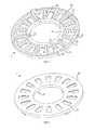
- FIG. 1shows a bottom perspective view of a magnet positioning device for an axial flux rotary motor in accordance with a preferred embodiment of the present invention
- FIG. 2shows a top perspective view of the magnet positioning device of FIG. 1 ;
- FIG. 3shows a bottom perspective view of the magnet positioning device shown in FIG. 1 together with magnets inserted therein;
- FIG. 4shows a bottom perspective view of the magnet positioning device of FIG. 1 as attached to a rotor
- FIG. 5shows a top perspective view of the magnet positioning device and rotor shown in FIG. 4 ;
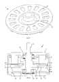
- FIG. 6shows a cross sectional side view of an axial flux rotary motor incorporating the magnet positioning device of FIG. 1 ;
- FIG. 7shows an exploded perspective view of the motor shown in FIG. 6 ;
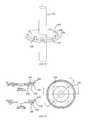
- FIG. 8shows an top perspective view of an alternative rotor for an axial flux motor
- FIG. 9shows a bottom perspective view of an alternative magnet positioning device for use with the rotor shown in FIG. 8 ;
- FIG. 10shows a top perspective view of the rotor of FIG. 8 together with the magnet positioning device of FIG. 9 ;
- FIG. 11shows a top perspective view of a further alternative magnet positioning device together with a rotor for an axial flux motor
- FIG. 12shows a bottom perspective view of the magnet positioning device and rotor of FIG. 11 ;
- FIG. 13shows a top view of the magnet positioning device and rotor shown in FIGS. 11 and 12 ;
- FIGS. 13 a and 13 bshow cross sectional side views taken along lines A-A and B-B, respectively, in FIG. 13 (but excluding the shaft which is shown in the previous figures);
- FIG. 14shows a cross sectional side view of the magnet positioning device and rotor shown in FIG. 11 ;
- FIG. 15shows a cut away top perspective view of the magnet positioning device and rotor shown in FIG. 11 ;
- FIG. 16shows a perspective view of a rotor for a linear motor
- FIG. 17shows a top perspective view of a magnet positioning device for the linear rotor shown in FIG. 16 ;
- FIG. 18shows a bottom perspective view of the magnet positioning device of FIG. 17 ;
- FIG. 19shows a top perspective view of the linear rotor shown in FIG. 16 together with the magnet positioning device shown in FIGS. 17 and 18 .
- top and bottomare used merely for convenience to refer to the embodiments shown in the accompanying drawings. It should accordingly be understood that these terms have no relevance to the orientation of the actual apparatus as it may be manufactured or used.
- FIGS. 1 to 7 of the drawingsshow a preferred embodiment of the present invention.
- FIGS. 1 and 2show bottom and top perspective views, respectively, of a magnet positioning device 1 for use in a permanent magnet axial flux electric motor 3 , as shown in FIGS. 6 and 7 .
- the components of the motorcan be best seen in the exploded view shown in FIG. 7 .
- These componentsinclude a housing, incorporating end shields 5 and 7 and a side wall 9 , a stator 11 (although the windings are not shown in the drawings) mounted within the housing.
- a rotor disc 13is mounted on a shaft 15 which is rotatable within the housing by means of bearings 17 and 19 .
- a wave washer 21is also included between the bearing 17 and the end shield 5 so as to reduce noise produced by the bearing and promote quieter operation of the motor 3 .
- the rotor disc 13includes a plurality of permanent magnets 23 , which are preferably neodymium magnets. As can also be seen in FIG. 6 , an air gap exists between the top face of the magnet positioning device 1 (attached to the rotor disc 13 ) and a lower face of the stator 11 .
- FIG. 1shows a first side of the body 25 of the magnet positioning device 1 , which is attachable to the rotor 13 .
- a bottom perspective view of the rotor disc 13 attached to the positioning device 1is shown in FIG. 4 and a top perspective view is shown in FIG. 5 .
- FIG. 2shows a second side of the body 25 of the magnet positioning device 1 which, in the assembled motor shown in FIG. 6 , faces the air gap.
- the body 25 of the magnet positioning device 1is made of a non ferrous and non electrically conductive material, such as a plastic of a suitable type. Examples may include Nylon, which might be glass fiber filled for increased strength or mineral filled for reduced cost.
- the body 25 of the device 1is of an annular shape and the first side of the annulus includes a plurality of recesses 27 . These recesses 27 are shaped so as to closely conform to the shape of the magnets 23 .
- FIG. 3shows a bottom perspective view of the magnet positioning device 1 together with magnets 23 inserted within the recesses 27 .
- the close conformity of the shape of the recesses 27 to the shape of the magnets 23serves to prevent the magnets 23 moving within the recesses 27 .
- the magnets 23are therefore separated from each other and a uniform spacing is maintained between them so as to prevent the magnets 23 being drawn together or being repelled.
- the recessesare formed by a plurality of ribs 29 which extend between inner and outer support rings 31 and 33 respectively. Together, these support rings 31 and 33 and separating ribs 29 form for a spider-like cage structure.
- the body 25 of the magnet positioning device 1includes connecting means for attaching the body 25 to the rotor disc 13 .
- the connecting meansis provided in the form of a plurality of clips 35 spaced around a peripheral edge of the body 25 .
- the body 25 of the magnet positioning device 1also includes locating means for aligning the body relative to the rotor disc 13 .
- the locating meansincludes four pins 37 projecting in an axial direction from the first side of the body 25 . These pins 37 engage with corresponding apertures 39 in the rotor disc 13 so as to facilitate alignment of the body 25 with the rotor disc 13 .
- the body 25 of the device 1also includes balancing means in the form of an annular groove 41 extending around a peripheral edge of the body 25 .
- the cross sectional shape of the groove 41is configured to enable weights, such as metal balls or wire, to be inserted and retained within the groove 41 . Any imbalance in the rotor 13 can thereby be corrected.
- the recesses 27extend all the way through the body 25 .
- the side wall of the recesses 27include a projecting flange, or shelf formation, 43 which prevents the magnets 23 passing all the way through the body 25 .
- the recessesmay not extend all the way through the body so that the second side of the body, facing the air gap, is fully covered.
- a method of assembling a permanent magnet axial flux motor 3will now be described. Initially, the magnets 23 are inserted into the recesses 27 from the first side of the body 25 . Once all of the magnets 23 have been inserted the positioning device 1 will appear as shown in FIG. 3 .
- the positioning device 1(including magnets 27 ) and the rotor disc 13 are then brought together but, before doing so, a ferrous object, such as an annular metal disc 28 (shown in FIG. 3 ), is brought into contact with the first side of the body.
- the magnets 23will thus be attracted to the ferrous object and thereby be held within their respective recesses 27 .
- the assemblycan then be brought into contact with the rotor disc 13 without the magnets 23 immediately being pulled out of the recesses 27 by the rotor disc 13 .
- the alignment pins 37will contact the surface of the rotor disc 13 .
- an adhesiveis applied to the magnets 23 , or to the rotor disc 13 , before the parts a brought together.
- the magnet positioning device 1together with the adhesive, would ensure that the magnets 23 do not separate from the rotor disc 13 during operation of the motor 3 .
- the connecting clips 35may be omitted.
- the magnet positioning devicemay be removable from the rotor disc once the adhesive has properly cured.
- FIG. 8shows a rotor 50 for an axial flux motor attached to a shaft 52 .
- the rotor 50includes four permanent magnets 54 .
- FIG. 9shows a magnet positioning device 56 for use with the rotor 50 shown in FIG. 8 .
- the magnet positioning device 56includes four recesses which are sized and shaped to conform to the magnets 54 shown in FIG. 8 .
- FIG. 10shows the magnet positioning device 56 brought together with the rotor 50 .
- FIGS. 11 to 15there is shown a magnet positioning device 156 , in accordance with a further alternative embodiment of the invention, attached to a rotor 150 for an axial flux motor.
- FIG. 11shows a top perspective view whereas FIG. 12 shows a bottom perspective view.
- FIG. 13shows a top view and FIGS. 13A and 13B show cross-sectional side views taken along lines A-A and B-B, respectively, in FIG. 13 .
- the shaft 152to which the rotor 150 is attached, has been omitted in these Figures.
- FIG. 14shows a cross-sectional side view of the rotor and magnet positioning device and
- FIG. 15shows a cutaway view of the same combination.
- the rotor 150is mounted on a shaft 152 and includes four magnets 154 .
- the magnet positioning device 156includes connecting clips 158 spaced around the periphery of the body of the positioning device 156 to attach it to the rotor 150 .
- the magnet positioning device 156also includes locating pins 160 which engage in corresponding apertures 162 in the rotor 150 .
- the magnet positioning device 156further includes an annular groove 164 to enable weights to be inserted and retained therein so as to enable any imbalance in the rotor 56 to be corrected.
- the method of assembly of the rotors shown in FIGS. 8 to 10 and 11 to 15is the same as the method involved in the assembly of the embodiment shown in FIGS. 1 to 7 .
- FIG. 16shows a rotor for the linear motor.
- the term “rotor”should be interpreted broadly to mean the moving part of the motor.
- the rotordoes not rotate in this instance but, instead, travels linearly with respect to a stator of the linear motor.
- the rotor 350includes permanent magnets 354 .
- FIGS. 17 and 18show top and bottom perspective views, respectively, of a magnet positioning device 356 in accordance with an embodiment of the present invention.
- the magnet positioning device 356includes recesses 358 therein for receiving corresponding magnets 354 as shown in FIG. 19 .
- the connecting meanscould include clips, as shown in the embodiments described herein, but could alternatively be formed by thermal deformation, ultrasonic welding or some other form of connection between the magnet positioning device and the rotor.
- the locating meansmay be in the form of projecting pins, as shown in the embodiments described herein, but could alternatively be corresponding formations within the magnet positioning device and rotor. Such alternatives are considered to be clearly within the scope of the appended claims.
Landscapes
- Engineering & Computer Science (AREA)
- Power Engineering (AREA)
- Manufacturing & Machinery (AREA)
- Permanent Field Magnets Of Synchronous Machinery (AREA)
Abstract
Description
Claims (13)
Applications Claiming Priority (3)
| Application Number | Priority Date | Filing Date | Title |
|---|---|---|---|
| AU2007902348AAU2007902348A0 (en) | 2007-05-03 | Rotor Magnet Positioning Device | |
| AU2007902348 | 2007-05-03 | ||
| PCT/AU2008/000591WO2008134796A1 (en) | 2007-05-03 | 2008-04-29 | Rotor magnet positioning device |
Related Parent Applications (1)
| Application Number | Title | Priority Date | Filing Date |
|---|---|---|---|
| PCT/AU2008/000591A-371-Of-InternationalWO2008134796A1 (en) | 2007-05-03 | 2008-04-29 | Rotor magnet positioning device |
Related Child Applications (1)
| Application Number | Title | Priority Date | Filing Date |
|---|---|---|---|
| US14/070,023ContinuationUS9467015B2 (en) | 2007-05-03 | 2013-11-01 | Rotor magnet positioning device |
Publications (2)
| Publication Number | Publication Date |
|---|---|
| US20100164316A1 US20100164316A1 (en) | 2010-07-01 |
| US8598761B2true US8598761B2 (en) | 2013-12-03 |
Family
ID=39943031
Family Applications (2)
| Application Number | Title | Priority Date | Filing Date |
|---|---|---|---|
| US12/598,652Active2029-06-10US8598761B2 (en) | 2007-05-03 | 2008-04-29 | Rotor magnet positioning device |
| US14/070,023Active2028-09-07US9467015B2 (en) | 2007-05-03 | 2013-11-01 | Rotor magnet positioning device |
Family Applications After (1)
| Application Number | Title | Priority Date | Filing Date |
|---|---|---|---|
| US14/070,023Active2028-09-07US9467015B2 (en) | 2007-05-03 | 2013-11-01 | Rotor magnet positioning device |
Country Status (2)
| Country | Link |
|---|---|
| US (2) | US8598761B2 (en) |
| WO (1) | WO2008134796A1 (en) |
Cited By (18)
| Publication number | Priority date | Publication date | Assignee | Title |
|---|---|---|---|---|
| US20150349596A1 (en)* | 2012-12-19 | 2015-12-03 | Leantec Motor Gmbh | Method for producing a rotor for an electric motor |
| US20170016449A1 (en)* | 2015-07-14 | 2017-01-19 | Hamilton Sundstrand Corporation | Axial-flux induction motor pump |
| US9673684B2 (en) | 2015-10-02 | 2017-06-06 | E-Circuit Motors, Inc. | Structures and methods for thermal management in printed circuit board stators |
| US9673688B2 (en) | 2015-10-02 | 2017-06-06 | E-Circuit Motors, Inc. | Apparatus and method for forming a magnet assembly |
| US9800109B2 (en) | 2015-10-02 | 2017-10-24 | E-Circuit Motors, Inc. | Structures and methods for controlling losses in printed circuit boards |
| US9859763B2 (en) | 2015-10-02 | 2018-01-02 | E-Circuit Motors, Inc. | Structures and methods for controlling losses in printed circuit boards |
| US10141822B2 (en) | 2015-05-04 | 2018-11-27 | Launchpoint Technologies, Inc. | Axial flux brushless permanent magnet electrical machine rotor |
| US10170953B2 (en) | 2015-10-02 | 2019-01-01 | E-Circuit Motors, Inc. | Planar composite structures and assemblies for axial flux motors and generators |
| US10916984B2 (en) | 2018-03-27 | 2021-02-09 | Regal Beloit America, Inc. | Axial flux rotor and axial flux electric machine |
| US10951098B2 (en) | 2018-03-27 | 2021-03-16 | Regal Beloit America, Inc. | Method of manufacturing an axial flux motor |
| US11005322B2 (en) | 2017-06-05 | 2021-05-11 | E-Circuit Motors, Inc. | Rotor assemblies for axial flux machines |
| US11025111B2 (en) | 2016-03-01 | 2021-06-01 | Regal Beloit Australia Pty Ltd | Rotor, electric machine and associated method |
| US11121614B2 (en) | 2017-06-05 | 2021-09-14 | E-Circuit Motors, Inc. | Pre-warped rotors for control of magnet-stator gap in axial flux machines |
| US11336130B1 (en) | 2021-08-17 | 2022-05-17 | E-Circuit Motors, Inc. | Low-loss planar winding configurations for an axial flux machine |
| US11527933B2 (en) | 2015-10-02 | 2022-12-13 | E-Circuit Motors, Inc. | Stator and rotor design for periodic torque requirements |
| US11626779B2 (en) | 2021-02-17 | 2023-04-11 | E-Circuit Motors, Inc. | Planar stator having discrete segments with different winding characteristics |
| US11751330B2 (en) | 2021-07-30 | 2023-09-05 | E-Circuit Motors, Inc. | Magnetic material filled printed circuit boards and printed circuit board stators |
| US11831211B2 (en) | 2017-06-05 | 2023-11-28 | E-Circuit Motors, Inc. | Stator and rotor design for periodic torque requirements |
Families Citing this family (28)
| Publication number | Priority date | Publication date | Assignee | Title |
|---|---|---|---|---|
| GB0800225D0 (en)* | 2008-01-07 | 2008-02-13 | Evo Electric Ltd | A rotor for an electrical machine |
| ES2519166T3 (en)* | 2010-01-20 | 2014-11-06 | Siemens Aktiengesellschaft | Magnet set |
| TWI465006B (en) | 2011-12-02 | 2014-12-11 | Ind Tech Res Inst | Stator assembly structure for axial flux electric machine |
| CN102497062B (en)* | 2011-12-22 | 2013-11-27 | 浙江大学 | Automatic assembly working head device for curved surface magnet of voice coil motor |
| BR112015004409A2 (en)* | 2012-10-05 | 2017-07-04 | Koninklijke Philips Nv | rotary positioning device |
| DE202012012228U1 (en)* | 2012-12-20 | 2013-02-01 | Klaus-Dieter Nies | Rotor for a machine shaft of an electric axial flux machine |
| US9467030B2 (en) | 2013-03-15 | 2016-10-11 | Regal Beloit Australia Pty Ltd | Air-cooled electric machine and method of assembling the same |
| CN104143885B (en)* | 2013-05-09 | 2017-02-08 | 上海电气集团上海电机厂有限公司 | Stator and rotor penetrating method for ultra-high-speed permanent magnet motor |
| US9711279B2 (en) | 2013-10-28 | 2017-07-18 | Infineon Technologies Austria Ag | DC-DC converter assembly with an output inductor accommodating a power stage attached to a circuit board |
| TWI526623B (en)* | 2014-01-27 | 2016-03-21 | 台達電子工業股份有限公司 | Maget module and fan comprising maget module |
| EP3257138B1 (en)* | 2015-02-13 | 2019-12-04 | Electric Vehicle Systems And Technology Pty Ltd | Electric motor |
| US10333407B2 (en)* | 2015-05-06 | 2019-06-25 | Infineon Technologies Austria Ag | Power stage packages of a multi-phase DC-DC converter under a coupled inductor |
| US10855178B2 (en) | 2015-05-29 | 2020-12-01 | Infineon Technologies Austria Ag | Discrete power stage transistor dies of a DC-DC converter under an inductor |
| US10770940B2 (en)* | 2017-01-31 | 2020-09-08 | Regal Beloit Australia Pty Ltd. | Modular rotors for axial flux electric machines |
| CN110945752B (en)* | 2017-01-31 | 2022-01-25 | 雷勃澳大利亚私人有限公司 | Modular stator and rotor for axial flux electric machine and method of assembly |
| CN115347697A (en)* | 2017-05-26 | 2022-11-15 | 靛蓝技术股份有限公司 | Magnetic Rotor Assembly |
| IT201900015402A1 (en)* | 2019-09-02 | 2021-03-02 | Texa Dynamics S R L | "Electric motor rotor" |
| CN110768484B (en)* | 2019-11-29 | 2024-12-03 | 广州大学 | A method and tooling for assembling rotor magnetic steel of an axial flux motor |
| CN112018977B (en)* | 2020-08-04 | 2025-06-17 | 浙江联宜电机有限公司 | Casing and magnetic tile bonding auxiliary device |
| CN112134381B (en)* | 2020-08-19 | 2023-03-24 | 沈阳工业大学 | Built-in magnetic steel composite pole rotor for axial flux permanent magnet motor |
| CN114552829A (en)* | 2020-11-20 | 2022-05-27 | 群光电能科技(台州)有限公司 | motor |
| CN112697008B (en)* | 2020-12-16 | 2025-06-13 | 天津市天发重型水电设备制造有限公司 | A tool for detecting the welding position of the gear strip of a tubular turbine generator |
| CN117356014A (en)* | 2021-02-08 | 2024-01-05 | 磁雷革传动系统有限公司 | Rotor for an axial flux electric machine and method of manufacture |
| CN113422481A (en)* | 2021-07-06 | 2021-09-21 | 浙江盘毂动力科技有限公司 | Disk motor rotor, and manufacturing apparatus and manufacturing method |
| DE102021210640A1 (en)* | 2021-09-23 | 2023-03-23 | Rolls-Royce Deutschland Ltd & Co Kg | Magnetic device for an electric machine |
| WO2023102241A1 (en) | 2021-12-03 | 2023-06-08 | Omni Powertrain Technologies, Llc | Two speed gearbox |
| US12176770B2 (en) | 2023-02-24 | 2024-12-24 | E-Circuit Motors, Inc. | Method for placing magnet segments for an axial flux machine |
| US12368356B1 (en)* | 2024-10-22 | 2025-07-22 | E-Circuit Motors, Inc. | Housing for axial flux motor assemblies |
Citations (31)
| Publication number | Priority date | Publication date | Assignee | Title |
|---|---|---|---|---|
| US3121814A (en)* | 1957-12-12 | 1964-02-18 | L R Power Corp | Dynamoelectric machine |
| US3678314A (en)* | 1970-06-17 | 1972-07-18 | Alastair Howroyd Carter | Discoidal electric motor |
| US4060745A (en)* | 1976-03-25 | 1977-11-29 | Sundstrand Corporation | Structure for attaching a permanent magnet to a rotating shaft |
| US4259603A (en)* | 1977-02-25 | 1981-03-31 | Sony Corporation | Electric motor |
| EP0052878B1 (en) | 1980-11-25 | 1985-08-21 | TDK Corporation | Magnetic wedge |
| US4656379A (en)* | 1985-12-18 | 1987-04-07 | The Garrett Corporation | Hybrid excited generator with flux control of consequent-pole rotor |
| US4877986A (en)* | 1987-05-19 | 1989-10-31 | Mitsubishi Denki Kabushiki Kaisha | Rotor of magnetic generator |
| US5608281A (en)* | 1994-11-07 | 1997-03-04 | U.S. Philips Corporation | Induction motor |
| US5691589A (en)* | 1995-06-30 | 1997-11-25 | Kaman Electromagnetics Corporation | Detachable magnet carrier for permanent magnet motor |
| US5952742A (en)* | 1995-02-03 | 1999-09-14 | Krauss-Maffei Ag | Synchronous linear motor with improved means for positioning and fastening permanent magnets |
| US6078121A (en)* | 1997-02-21 | 2000-06-20 | Emerson Electric Co. | Rotor assembly for a rotating machine |
| US6232690B1 (en)* | 1997-03-04 | 2001-05-15 | Papst-Motoren Gmbh & Co. Kg | Electronically commutated DC |
| US6373162B1 (en)* | 1999-11-11 | 2002-04-16 | Ford Global Technologies, Inc. | Permanent magnet electric machine with flux control |
| US20020175582A1 (en)* | 2000-07-21 | 2002-11-28 | Edward Lopatinsky | Electric drive |
| US20030107291A1 (en)* | 2001-03-09 | 2003-06-12 | Hitachi, Ltd. | Permanent magnet type rotating electric machine |
| US6605883B2 (en)* | 2001-04-20 | 2003-08-12 | Japan Servo Co., Ltd. | Multi-phase flat-type PM stepping motor and driving circuit thereof |
| US20050194855A1 (en)* | 2004-03-03 | 2005-09-08 | Masahiro Hasebe | Axial gap rotating electrical machine |
| US20050210663A1 (en) | 2003-03-07 | 2005-09-29 | Tsuyoshi Ishida | Magnetizing jig, magnetizing method using the jig, and method of assembling electric compressor by using the jig and the magnetizing method |
| US20050246886A1 (en)* | 2004-05-07 | 2005-11-10 | Jean-Pierre Morel | Method and device for positioning and affixing magnets on a magnetic yoke member of a motor |
| US20060063403A1 (en) | 2004-09-21 | 2006-03-23 | Nidec Corporation | Motor |
| US20060113855A1 (en)* | 2004-11-26 | 2006-06-01 | Metal Industries Research And Development Centre | Low cogging and easy-to-downsize spindle motor structure |
| US20060138890A1 (en)* | 2004-12-14 | 2006-06-29 | Nissan Motor Co., Ltd. | Rotor structure of an axial gap rotating electrical device |
| US7081696B2 (en)* | 2004-08-12 | 2006-07-25 | Exro Technologies Inc. | Polyphasic multi-coil generator |
| US20060284507A1 (en)* | 2005-06-16 | 2006-12-21 | Fujitsu General Limited | Axial air gap-type electric motor |
| US20070013251A1 (en)* | 2005-07-14 | 2007-01-18 | Zoran Djuric | PDC motor-generator |
| US20070029889A1 (en)* | 2005-08-05 | 2007-02-08 | Tom Dunn | Electro-motive machine using halbach array |
| US20070040465A1 (en)* | 2004-09-02 | 2007-02-22 | Nazar Al-Khayat | Alternator assembly |
| US20070046124A1 (en)* | 2005-09-01 | 2007-03-01 | Metin Aydin | Field controlled axial flux permanent magnet electrical machine |
| US20070096571A1 (en)* | 2004-06-21 | 2007-05-03 | Yuratich Michael A | Electric submersible pumps |
| US20080042515A1 (en)* | 2006-08-17 | 2008-02-21 | Paul Butterfield | Optimized modular electrical machine using permanent magnets |
| US20080088200A1 (en)* | 2006-06-08 | 2008-04-17 | Jonathan Ritchey | Poly-phasic multi-coil generator |
Family Cites Families (2)
| Publication number | Priority date | Publication date | Assignee | Title |
|---|---|---|---|---|
| JP2002325403A (en)* | 2001-04-27 | 2002-11-08 | Mitsubishi Electric Corp | Magnet generator, method for manufacturing magnet generator, and resin mold for manufacturing magnet generator |
| JP3996919B2 (en)* | 2004-08-20 | 2007-10-24 | 信越化学工業株式会社 | Permanent magnet motor |
- 2008
- 2008-04-29USUS12/598,652patent/US8598761B2/enactiveActive
- 2008-04-29WOPCT/AU2008/000591patent/WO2008134796A1/enactiveApplication Filing
- 2013
- 2013-11-01USUS14/070,023patent/US9467015B2/enactiveActive
Patent Citations (33)
| Publication number | Priority date | Publication date | Assignee | Title |
|---|---|---|---|---|
| US3121814A (en)* | 1957-12-12 | 1964-02-18 | L R Power Corp | Dynamoelectric machine |
| US3678314A (en)* | 1970-06-17 | 1972-07-18 | Alastair Howroyd Carter | Discoidal electric motor |
| US4060745A (en)* | 1976-03-25 | 1977-11-29 | Sundstrand Corporation | Structure for attaching a permanent magnet to a rotating shaft |
| US4259603A (en)* | 1977-02-25 | 1981-03-31 | Sony Corporation | Electric motor |
| EP0052878B1 (en) | 1980-11-25 | 1985-08-21 | TDK Corporation | Magnetic wedge |
| US4656379A (en)* | 1985-12-18 | 1987-04-07 | The Garrett Corporation | Hybrid excited generator with flux control of consequent-pole rotor |
| US4877986A (en)* | 1987-05-19 | 1989-10-31 | Mitsubishi Denki Kabushiki Kaisha | Rotor of magnetic generator |
| US5608281A (en)* | 1994-11-07 | 1997-03-04 | U.S. Philips Corporation | Induction motor |
| US5952742A (en)* | 1995-02-03 | 1999-09-14 | Krauss-Maffei Ag | Synchronous linear motor with improved means for positioning and fastening permanent magnets |
| US5691589A (en)* | 1995-06-30 | 1997-11-25 | Kaman Electromagnetics Corporation | Detachable magnet carrier for permanent magnet motor |
| US5831365A (en)* | 1995-06-30 | 1998-11-03 | Kaman Electromagnetics Corporation | Detachable magnet carrier for permanent magnet motor |
| US6078121A (en)* | 1997-02-21 | 2000-06-20 | Emerson Electric Co. | Rotor assembly for a rotating machine |
| US6232690B1 (en)* | 1997-03-04 | 2001-05-15 | Papst-Motoren Gmbh & Co. Kg | Electronically commutated DC |
| US6373162B1 (en)* | 1999-11-11 | 2002-04-16 | Ford Global Technologies, Inc. | Permanent magnet electric machine with flux control |
| US20020175582A1 (en)* | 2000-07-21 | 2002-11-28 | Edward Lopatinsky | Electric drive |
| US20030107291A1 (en)* | 2001-03-09 | 2003-06-12 | Hitachi, Ltd. | Permanent magnet type rotating electric machine |
| US6605883B2 (en)* | 2001-04-20 | 2003-08-12 | Japan Servo Co., Ltd. | Multi-phase flat-type PM stepping motor and driving circuit thereof |
| US20050210663A1 (en) | 2003-03-07 | 2005-09-29 | Tsuyoshi Ishida | Magnetizing jig, magnetizing method using the jig, and method of assembling electric compressor by using the jig and the magnetizing method |
| US20050194855A1 (en)* | 2004-03-03 | 2005-09-08 | Masahiro Hasebe | Axial gap rotating electrical machine |
| US7187098B2 (en)* | 2004-03-03 | 2007-03-06 | Kabushikikaisha Equos Research | Axial gap rotating electrical machine |
| US20050246886A1 (en)* | 2004-05-07 | 2005-11-10 | Jean-Pierre Morel | Method and device for positioning and affixing magnets on a magnetic yoke member of a motor |
| US20070096571A1 (en)* | 2004-06-21 | 2007-05-03 | Yuratich Michael A | Electric submersible pumps |
| US7081696B2 (en)* | 2004-08-12 | 2006-07-25 | Exro Technologies Inc. | Polyphasic multi-coil generator |
| US20070040465A1 (en)* | 2004-09-02 | 2007-02-22 | Nazar Al-Khayat | Alternator assembly |
| US20060063403A1 (en) | 2004-09-21 | 2006-03-23 | Nidec Corporation | Motor |
| US20060113855A1 (en)* | 2004-11-26 | 2006-06-01 | Metal Industries Research And Development Centre | Low cogging and easy-to-downsize spindle motor structure |
| US20060138890A1 (en)* | 2004-12-14 | 2006-06-29 | Nissan Motor Co., Ltd. | Rotor structure of an axial gap rotating electrical device |
| US20060284507A1 (en)* | 2005-06-16 | 2006-12-21 | Fujitsu General Limited | Axial air gap-type electric motor |
| US20070013251A1 (en)* | 2005-07-14 | 2007-01-18 | Zoran Djuric | PDC motor-generator |
| US20070029889A1 (en)* | 2005-08-05 | 2007-02-08 | Tom Dunn | Electro-motive machine using halbach array |
| US20070046124A1 (en)* | 2005-09-01 | 2007-03-01 | Metin Aydin | Field controlled axial flux permanent magnet electrical machine |
| US20080088200A1 (en)* | 2006-06-08 | 2008-04-17 | Jonathan Ritchey | Poly-phasic multi-coil generator |
| US20080042515A1 (en)* | 2006-08-17 | 2008-02-21 | Paul Butterfield | Optimized modular electrical machine using permanent magnets |
Non-Patent Citations (1)
| Title |
|---|
| International Preliminary Report on Patentability and Written Opinion of PCT/AU2008/000591 dated Jul. 10, 2009. |
Cited By (24)
| Publication number | Priority date | Publication date | Assignee | Title |
|---|---|---|---|---|
| US10090721B2 (en)* | 2012-12-19 | 2018-10-02 | Leantec Motor Gmbh | Method for producing a rotor for an electric motor |
| US20150349596A1 (en)* | 2012-12-19 | 2015-12-03 | Leantec Motor Gmbh | Method for producing a rotor for an electric motor |
| US10141822B2 (en) | 2015-05-04 | 2018-11-27 | Launchpoint Technologies, Inc. | Axial flux brushless permanent magnet electrical machine rotor |
| US20170016449A1 (en)* | 2015-07-14 | 2017-01-19 | Hamilton Sundstrand Corporation | Axial-flux induction motor pump |
| US9800109B2 (en) | 2015-10-02 | 2017-10-24 | E-Circuit Motors, Inc. | Structures and methods for controlling losses in printed circuit boards |
| US9859763B2 (en) | 2015-10-02 | 2018-01-02 | E-Circuit Motors, Inc. | Structures and methods for controlling losses in printed circuit boards |
| US11527933B2 (en) | 2015-10-02 | 2022-12-13 | E-Circuit Motors, Inc. | Stator and rotor design for periodic torque requirements |
| US9673688B2 (en) | 2015-10-02 | 2017-06-06 | E-Circuit Motors, Inc. | Apparatus and method for forming a magnet assembly |
| US10170953B2 (en) | 2015-10-02 | 2019-01-01 | E-Circuit Motors, Inc. | Planar composite structures and assemblies for axial flux motors and generators |
| US10211694B1 (en) | 2015-10-02 | 2019-02-19 | E-Circuit Motors, Inc. | Structures and methods for thermal management in printed circuit board stators |
| US10256690B2 (en) | 2015-10-02 | 2019-04-09 | E-Circuit Motors, Inc. | Structures and methods for controlling losses in printed circuit boards |
| US9673684B2 (en) | 2015-10-02 | 2017-06-06 | E-Circuit Motors, Inc. | Structures and methods for thermal management in printed circuit board stators |
| US11025111B2 (en) | 2016-03-01 | 2021-06-01 | Regal Beloit Australia Pty Ltd | Rotor, electric machine and associated method |
| US11855484B2 (en) | 2017-06-05 | 2023-12-26 | E-Circuit Motors, Inc. | Rotor assemblies for axial flux machines |
| US11005322B2 (en) | 2017-06-05 | 2021-05-11 | E-Circuit Motors, Inc. | Rotor assemblies for axial flux machines |
| US11121614B2 (en) | 2017-06-05 | 2021-09-14 | E-Circuit Motors, Inc. | Pre-warped rotors for control of magnet-stator gap in axial flux machines |
| US11831211B2 (en) | 2017-06-05 | 2023-11-28 | E-Circuit Motors, Inc. | Stator and rotor design for periodic torque requirements |
| US10951098B2 (en) | 2018-03-27 | 2021-03-16 | Regal Beloit America, Inc. | Method of manufacturing an axial flux motor |
| US10916984B2 (en) | 2018-03-27 | 2021-02-09 | Regal Beloit America, Inc. | Axial flux rotor and axial flux electric machine |
| US11942837B2 (en) | 2018-03-27 | 2024-03-26 | Regal Beloit America, Inc. | Axial flux rotor preparation process |
| US11626779B2 (en) | 2021-02-17 | 2023-04-11 | E-Circuit Motors, Inc. | Planar stator having discrete segments with different winding characteristics |
| US12424901B2 (en) | 2021-02-17 | 2025-09-23 | E-Circuit Motors, Inc. | Planar stator configurations for axial flux machines |
| US11751330B2 (en) | 2021-07-30 | 2023-09-05 | E-Circuit Motors, Inc. | Magnetic material filled printed circuit boards and printed circuit board stators |
| US11336130B1 (en) | 2021-08-17 | 2022-05-17 | E-Circuit Motors, Inc. | Low-loss planar winding configurations for an axial flux machine |
Also Published As
| Publication number | Publication date |
|---|---|
| US20100164316A1 (en) | 2010-07-01 |
| US9467015B2 (en) | 2016-10-11 |
| US20140062246A1 (en) | 2014-03-06 |
| WO2008134796A1 (en) | 2008-11-13 |
Similar Documents
| Publication | Publication Date | Title |
|---|---|---|
| US8598761B2 (en) | Rotor magnet positioning device | |
| JP6208334B2 (en) | Axial air gap type rotating electrical machine | |
| US10491068B2 (en) | Motor using complex magnetic flux | |
| US20040194286A1 (en) | Method of making a ring-magnet assembly | |
| EP3631956B1 (en) | Magnetic rotor assembly | |
| CN109713819A (en) | A kind of high intensity Halbach permanent magnet array rotor structure | |
| MX2007002988A (en) | Brushless electric motor. | |
| CN1084542C (en) | Rotor assembling method, and motor having such rotor | |
| EP1715560B1 (en) | System for securing permanent magnets | |
| US9837867B2 (en) | Electric machine, rotor and associated method | |
| JP5312228B2 (en) | Permanent magnet rotating electric machine | |
| KR20210076825A (en) | Axial field flow rotating machine | |
| JP2006034024A (en) | Permanent magnet rotor of rotating electrical machine | |
| EP1841047A1 (en) | Armature, motor, compressor and method for manufacturing them | |
| CN109428417B (en) | Rotor and rotating electrical machine | |
| US20150349615A1 (en) | Method of Constructing a Rotor for a Line Start Interior Permanent Magnet Motor | |
| JP2021521762A (en) | Winding type rotor for synchronous electromechanical machines | |
| US20180291914A1 (en) | Fan motor | |
| JP6593881B2 (en) | Manufacturing method of axial gap type rotating electrical machine | |
| JP2013172642A (en) | Fitting system for fitting plurality of magnetic members in electric machine using permanent magnet | |
| CN115765239A (en) | Brushless motor rotor and assembling method thereof | |
| WO2018047603A1 (en) | Pump motor | |
| JP6705385B2 (en) | Rotor of rotating electric machine | |
| KR102684606B1 (en) | Axial field flow rotating machine | |
| EP4439939A1 (en) | Motor |
Legal Events
| Date | Code | Title | Description |
|---|---|---|---|
| AS | Assignment | Owner name:IN MOTION TECHNOLOGIES PTY., LTD.,AUSTRALIA Free format text:ASSIGNMENT OF ASSIGNORS INTEREST;ASSIGNORS:LANGFORD, CHARLES RICHARD;CAMILLERI, STEVEN PETER;PATTERSON, DEAN JAMES;SIGNING DATES FROM 20100511 TO 20100526;REEL/FRAME:024495/0645 Owner name:IN MOTION TECHNOLOGIES PTY., LTD., AUSTRALIA Free format text:ASSIGNMENT OF ASSIGNORS INTEREST;ASSIGNORS:LANGFORD, CHARLES RICHARD;CAMILLERI, STEVEN PETER;PATTERSON, DEAN JAMES;SIGNING DATES FROM 20100511 TO 20100526;REEL/FRAME:024495/0645 | |
| FEPP | Fee payment procedure | Free format text:PAYOR NUMBER ASSIGNED (ORIGINAL EVENT CODE: ASPN); ENTITY STATUS OF PATENT OWNER: LARGE ENTITY | |
| STCF | Information on status: patent grant | Free format text:PATENTED CASE | |
| AS | Assignment | Owner name:REGAL BELOIT AUSTRALIA PTY LTD, AUSTRALIA Free format text:DEED OF ASSIGNMENT OF PATENTS;ASSIGNOR:IN MOTION TECHNOLOGIES PTY LTD;REEL/FRAME:040566/0270 Effective date:20160509 | |
| FPAY | Fee payment | Year of fee payment:4 | |
| MAFP | Maintenance fee payment | Free format text:PAYMENT OF MAINTENANCE FEE, 8TH YEAR, LARGE ENTITY (ORIGINAL EVENT CODE: M1552); ENTITY STATUS OF PATENT OWNER: LARGE ENTITY Year of fee payment:8 | |
| AS | Assignment | Owner name:REXNORD AUSTRALIA PTY LTD, AUSTRALIA Free format text:ASSIGNMENT OF ASSIGNORS INTEREST;ASSIGNOR:REGAL BELOIT AUSTRALIA PTY LTD;REEL/FRAME:069437/0129 Effective date:20240425 | |
| MAFP | Maintenance fee payment | Free format text:PAYMENT OF MAINTENANCE FEE, 12TH YEAR, LARGE ENTITY (ORIGINAL EVENT CODE: M1553); ENTITY STATUS OF PATENT OWNER: LARGE ENTITY Year of fee payment:12 |