US8597298B2 - Proximal reamer - Google Patents
Proximal reamerDownload PDFInfo
- Publication number
- US8597298B2 US8597298B2US11/529,799US52979906AUS8597298B2US 8597298 B2US8597298 B2US 8597298B2US 52979906 AUS52979906 AUS 52979906AUS 8597298 B2US8597298 B2US 8597298B2
- Authority
- US
- United States
- Prior art keywords
- sleeve
- reamer
- stem
- implant
- proximal
- Prior art date
- Legal status (The legal status is an assumption and is not a legal conclusion. Google has not performed a legal analysis and makes no representation as to the accuracy of the status listed.)
- Active, expires
Links
Images


Classifications
- A—HUMAN NECESSITIES
- A61—MEDICAL OR VETERINARY SCIENCE; HYGIENE
- A61B—DIAGNOSIS; SURGERY; IDENTIFICATION
- A61B17/00—Surgical instruments, devices or methods
- A61B17/16—Instruments for performing osteoclasis; Drills or chisels for bones; Trepans
- A—HUMAN NECESSITIES
- A61—MEDICAL OR VETERINARY SCIENCE; HYGIENE
- A61B—DIAGNOSIS; SURGERY; IDENTIFICATION
- A61B17/00—Surgical instruments, devices or methods
- A61B17/16—Instruments for performing osteoclasis; Drills or chisels for bones; Trepans
- A61B17/1662—Instruments for performing osteoclasis; Drills or chisels for bones; Trepans for particular parts of the body
- A61B17/1664—Instruments for performing osteoclasis; Drills or chisels for bones; Trepans for particular parts of the body for the hip
- A61B17/1668—Instruments for performing osteoclasis; Drills or chisels for bones; Trepans for particular parts of the body for the hip for the upper femur
- A—HUMAN NECESSITIES
- A61—MEDICAL OR VETERINARY SCIENCE; HYGIENE
- A61B—DIAGNOSIS; SURGERY; IDENTIFICATION
- A61B17/00—Surgical instruments, devices or methods
- A61B17/16—Instruments for performing osteoclasis; Drills or chisels for bones; Trepans
- A61B17/1604—Chisels; Rongeurs; Punches; Stamps
- A—HUMAN NECESSITIES
- A61—MEDICAL OR VETERINARY SCIENCE; HYGIENE
- A61B—DIAGNOSIS; SURGERY; IDENTIFICATION
- A61B17/00—Surgical instruments, devices or methods
- A61B17/16—Instruments for performing osteoclasis; Drills or chisels for bones; Trepans
- A61B17/164—Instruments for performing osteoclasis; Drills or chisels for bones; Trepans intramedullary
- A—HUMAN NECESSITIES
- A61—MEDICAL OR VETERINARY SCIENCE; HYGIENE
- A61B—DIAGNOSIS; SURGERY; IDENTIFICATION
- A61B17/00—Surgical instruments, devices or methods
- A61B17/16—Instruments for performing osteoclasis; Drills or chisels for bones; Trepans
- A61B17/17—Guides or aligning means for drills, mills, pins or wires
- A61B17/1739—Guides or aligning means for drills, mills, pins or wires specially adapted for particular parts of the body
- A—HUMAN NECESSITIES
- A61—MEDICAL OR VETERINARY SCIENCE; HYGIENE
- A61F—FILTERS IMPLANTABLE INTO BLOOD VESSELS; PROSTHESES; DEVICES PROVIDING PATENCY TO, OR PREVENTING COLLAPSING OF, TUBULAR STRUCTURES OF THE BODY, e.g. STENTS; ORTHOPAEDIC, NURSING OR CONTRACEPTIVE DEVICES; FOMENTATION; TREATMENT OR PROTECTION OF EYES OR EARS; BANDAGES, DRESSINGS OR ABSORBENT PADS; FIRST-AID KITS
- A61F2/00—Filters implantable into blood vessels; Prostheses, i.e. artificial substitutes or replacements for parts of the body; Appliances for connecting them with the body; Devices providing patency to, or preventing collapsing of, tubular structures of the body, e.g. stents
- A61F2/02—Prostheses implantable into the body
- A61F2/30—Joints
- A61F2/32—Joints for the hip
- A61F2/36—Femoral heads ; Femoral endoprostheses
- A—HUMAN NECESSITIES
- A61—MEDICAL OR VETERINARY SCIENCE; HYGIENE
- A61F—FILTERS IMPLANTABLE INTO BLOOD VESSELS; PROSTHESES; DEVICES PROVIDING PATENCY TO, OR PREVENTING COLLAPSING OF, TUBULAR STRUCTURES OF THE BODY, e.g. STENTS; ORTHOPAEDIC, NURSING OR CONTRACEPTIVE DEVICES; FOMENTATION; TREATMENT OR PROTECTION OF EYES OR EARS; BANDAGES, DRESSINGS OR ABSORBENT PADS; FIRST-AID KITS
- A61F2/00—Filters implantable into blood vessels; Prostheses, i.e. artificial substitutes or replacements for parts of the body; Appliances for connecting them with the body; Devices providing patency to, or preventing collapsing of, tubular structures of the body, e.g. stents
- A61F2/02—Prostheses implantable into the body
- A61F2/30—Joints
- A61F2/46—Special tools for implanting artificial joints
- A61F2/4603—Special tools for implanting artificial joints for insertion or extraction of endoprosthetic joints or of accessories thereof
- A61F2/4607—Special tools for implanting artificial joints for insertion or extraction of endoprosthetic joints or of accessories thereof of hip femoral endoprostheses
- A—HUMAN NECESSITIES
- A61—MEDICAL OR VETERINARY SCIENCE; HYGIENE
- A61F—FILTERS IMPLANTABLE INTO BLOOD VESSELS; PROSTHESES; DEVICES PROVIDING PATENCY TO, OR PREVENTING COLLAPSING OF, TUBULAR STRUCTURES OF THE BODY, e.g. STENTS; ORTHOPAEDIC, NURSING OR CONTRACEPTIVE DEVICES; FOMENTATION; TREATMENT OR PROTECTION OF EYES OR EARS; BANDAGES, DRESSINGS OR ABSORBENT PADS; FIRST-AID KITS
- A61F2/00—Filters implantable into blood vessels; Prostheses, i.e. artificial substitutes or replacements for parts of the body; Appliances for connecting them with the body; Devices providing patency to, or preventing collapsing of, tubular structures of the body, e.g. stents
- A61F2/02—Prostheses implantable into the body
- A61F2/30—Joints
- A61F2/46—Special tools for implanting artificial joints
- A61F2/4657—Measuring instruments used for implanting artificial joints
- A—HUMAN NECESSITIES
- A61—MEDICAL OR VETERINARY SCIENCE; HYGIENE
- A61F—FILTERS IMPLANTABLE INTO BLOOD VESSELS; PROSTHESES; DEVICES PROVIDING PATENCY TO, OR PREVENTING COLLAPSING OF, TUBULAR STRUCTURES OF THE BODY, e.g. STENTS; ORTHOPAEDIC, NURSING OR CONTRACEPTIVE DEVICES; FOMENTATION; TREATMENT OR PROTECTION OF EYES OR EARS; BANDAGES, DRESSINGS OR ABSORBENT PADS; FIRST-AID KITS
- A61F2/00—Filters implantable into blood vessels; Prostheses, i.e. artificial substitutes or replacements for parts of the body; Appliances for connecting them with the body; Devices providing patency to, or preventing collapsing of, tubular structures of the body, e.g. stents
- A61F2/02—Prostheses implantable into the body
- A61F2/30—Joints
- A61F2/46—Special tools for implanting artificial joints
- A61F2/468—Testing instruments for artificial joints
- A—HUMAN NECESSITIES
- A61—MEDICAL OR VETERINARY SCIENCE; HYGIENE
- A61F—FILTERS IMPLANTABLE INTO BLOOD VESSELS; PROSTHESES; DEVICES PROVIDING PATENCY TO, OR PREVENTING COLLAPSING OF, TUBULAR STRUCTURES OF THE BODY, e.g. STENTS; ORTHOPAEDIC, NURSING OR CONTRACEPTIVE DEVICES; FOMENTATION; TREATMENT OR PROTECTION OF EYES OR EARS; BANDAGES, DRESSINGS OR ABSORBENT PADS; FIRST-AID KITS
- A61F2/00—Filters implantable into blood vessels; Prostheses, i.e. artificial substitutes or replacements for parts of the body; Appliances for connecting them with the body; Devices providing patency to, or preventing collapsing of, tubular structures of the body, e.g. stents
- A61F2/02—Prostheses implantable into the body
- A61F2/30—Joints
- A61F2/46—Special tools for implanting artificial joints
- A61F2/4684—Trial or dummy prostheses
- A—HUMAN NECESSITIES
- A61—MEDICAL OR VETERINARY SCIENCE; HYGIENE
- A61B—DIAGNOSIS; SURGERY; IDENTIFICATION
- A61B17/00—Surgical instruments, devices or methods
- A61B17/56—Surgical instruments or methods for treatment of bones or joints; Devices specially adapted therefor
- A61B2017/564—Methods for bone or joint treatment
- A—HUMAN NECESSITIES
- A61—MEDICAL OR VETERINARY SCIENCE; HYGIENE
- A61F—FILTERS IMPLANTABLE INTO BLOOD VESSELS; PROSTHESES; DEVICES PROVIDING PATENCY TO, OR PREVENTING COLLAPSING OF, TUBULAR STRUCTURES OF THE BODY, e.g. STENTS; ORTHOPAEDIC, NURSING OR CONTRACEPTIVE DEVICES; FOMENTATION; TREATMENT OR PROTECTION OF EYES OR EARS; BANDAGES, DRESSINGS OR ABSORBENT PADS; FIRST-AID KITS
- A61F2/00—Filters implantable into blood vessels; Prostheses, i.e. artificial substitutes or replacements for parts of the body; Appliances for connecting them with the body; Devices providing patency to, or preventing collapsing of, tubular structures of the body, e.g. stents
- A61F2/02—Prostheses implantable into the body
- A61F2/30—Joints
- A61F2/32—Joints for the hip
- A61F2/34—Acetabular cups
- A—HUMAN NECESSITIES
- A61—MEDICAL OR VETERINARY SCIENCE; HYGIENE
- A61F—FILTERS IMPLANTABLE INTO BLOOD VESSELS; PROSTHESES; DEVICES PROVIDING PATENCY TO, OR PREVENTING COLLAPSING OF, TUBULAR STRUCTURES OF THE BODY, e.g. STENTS; ORTHOPAEDIC, NURSING OR CONTRACEPTIVE DEVICES; FOMENTATION; TREATMENT OR PROTECTION OF EYES OR EARS; BANDAGES, DRESSINGS OR ABSORBENT PADS; FIRST-AID KITS
- A61F2/00—Filters implantable into blood vessels; Prostheses, i.e. artificial substitutes or replacements for parts of the body; Appliances for connecting them with the body; Devices providing patency to, or preventing collapsing of, tubular structures of the body, e.g. stents
- A61F2/02—Prostheses implantable into the body
- A61F2/30—Joints
- A61F2/32—Joints for the hip
- A61F2/36—Femoral heads ; Femoral endoprostheses
- A61F2/3662—Femoral shafts
- A61F2/367—Proximal or metaphyseal parts of shafts
- A—HUMAN NECESSITIES
- A61—MEDICAL OR VETERINARY SCIENCE; HYGIENE
- A61F—FILTERS IMPLANTABLE INTO BLOOD VESSELS; PROSTHESES; DEVICES PROVIDING PATENCY TO, OR PREVENTING COLLAPSING OF, TUBULAR STRUCTURES OF THE BODY, e.g. STENTS; ORTHOPAEDIC, NURSING OR CONTRACEPTIVE DEVICES; FOMENTATION; TREATMENT OR PROTECTION OF EYES OR EARS; BANDAGES, DRESSINGS OR ABSORBENT PADS; FIRST-AID KITS
- A61F2/00—Filters implantable into blood vessels; Prostheses, i.e. artificial substitutes or replacements for parts of the body; Appliances for connecting them with the body; Devices providing patency to, or preventing collapsing of, tubular structures of the body, e.g. stents
- A61F2/02—Prostheses implantable into the body
- A61F2/30—Joints
- A61F2/32—Joints for the hip
- A61F2/36—Femoral heads ; Femoral endoprostheses
- A61F2/3662—Femoral shafts
- A61F2/3676—Distal or diaphyseal parts of shafts
- A—HUMAN NECESSITIES
- A61—MEDICAL OR VETERINARY SCIENCE; HYGIENE
- A61F—FILTERS IMPLANTABLE INTO BLOOD VESSELS; PROSTHESES; DEVICES PROVIDING PATENCY TO, OR PREVENTING COLLAPSING OF, TUBULAR STRUCTURES OF THE BODY, e.g. STENTS; ORTHOPAEDIC, NURSING OR CONTRACEPTIVE DEVICES; FOMENTATION; TREATMENT OR PROTECTION OF EYES OR EARS; BANDAGES, DRESSINGS OR ABSORBENT PADS; FIRST-AID KITS
- A61F2/00—Filters implantable into blood vessels; Prostheses, i.e. artificial substitutes or replacements for parts of the body; Appliances for connecting them with the body; Devices providing patency to, or preventing collapsing of, tubular structures of the body, e.g. stents
- A61F2/02—Prostheses implantable into the body
- A61F2/30—Joints
- A61F2002/30001—Additional features of subject-matter classified in A61F2/28, A61F2/30 and subgroups thereof
- A61F2002/30108—Shapes
- A61F2002/30199—Three-dimensional shapes
- A61F2002/30224—Three-dimensional shapes cylindrical
- A—HUMAN NECESSITIES
- A61—MEDICAL OR VETERINARY SCIENCE; HYGIENE
- A61F—FILTERS IMPLANTABLE INTO BLOOD VESSELS; PROSTHESES; DEVICES PROVIDING PATENCY TO, OR PREVENTING COLLAPSING OF, TUBULAR STRUCTURES OF THE BODY, e.g. STENTS; ORTHOPAEDIC, NURSING OR CONTRACEPTIVE DEVICES; FOMENTATION; TREATMENT OR PROTECTION OF EYES OR EARS; BANDAGES, DRESSINGS OR ABSORBENT PADS; FIRST-AID KITS
- A61F2/00—Filters implantable into blood vessels; Prostheses, i.e. artificial substitutes or replacements for parts of the body; Appliances for connecting them with the body; Devices providing patency to, or preventing collapsing of, tubular structures of the body, e.g. stents
- A61F2/02—Prostheses implantable into the body
- A61F2/30—Joints
- A61F2002/30001—Additional features of subject-matter classified in A61F2/28, A61F2/30 and subgroups thereof
- A61F2002/30316—The prosthesis having different structural features at different locations within the same prosthesis; Connections between prosthetic parts; Special structural features of bone or joint prostheses not otherwise provided for
- A61F2002/30317—The prosthesis having different structural features at different locations within the same prosthesis
- A61F2002/30322—The prosthesis having different structural features at different locations within the same prosthesis differing in surface structures
- A—HUMAN NECESSITIES
- A61—MEDICAL OR VETERINARY SCIENCE; HYGIENE
- A61F—FILTERS IMPLANTABLE INTO BLOOD VESSELS; PROSTHESES; DEVICES PROVIDING PATENCY TO, OR PREVENTING COLLAPSING OF, TUBULAR STRUCTURES OF THE BODY, e.g. STENTS; ORTHOPAEDIC, NURSING OR CONTRACEPTIVE DEVICES; FOMENTATION; TREATMENT OR PROTECTION OF EYES OR EARS; BANDAGES, DRESSINGS OR ABSORBENT PADS; FIRST-AID KITS
- A61F2/00—Filters implantable into blood vessels; Prostheses, i.e. artificial substitutes or replacements for parts of the body; Appliances for connecting them with the body; Devices providing patency to, or preventing collapsing of, tubular structures of the body, e.g. stents
- A61F2/02—Prostheses implantable into the body
- A61F2/30—Joints
- A61F2002/30001—Additional features of subject-matter classified in A61F2/28, A61F2/30 and subgroups thereof
- A61F2002/30316—The prosthesis having different structural features at different locations within the same prosthesis; Connections between prosthetic parts; Special structural features of bone or joint prostheses not otherwise provided for
- A61F2002/30329—Connections or couplings between prosthetic parts, e.g. between modular parts; Connecting elements
- A61F2002/30331—Connections or couplings between prosthetic parts, e.g. between modular parts; Connecting elements made by longitudinally pushing a protrusion into a complementarily-shaped recess, e.g. held by friction fit
- A61F2002/30332—Conically- or frustoconically-shaped protrusion and recess
- A—HUMAN NECESSITIES
- A61—MEDICAL OR VETERINARY SCIENCE; HYGIENE
- A61F—FILTERS IMPLANTABLE INTO BLOOD VESSELS; PROSTHESES; DEVICES PROVIDING PATENCY TO, OR PREVENTING COLLAPSING OF, TUBULAR STRUCTURES OF THE BODY, e.g. STENTS; ORTHOPAEDIC, NURSING OR CONTRACEPTIVE DEVICES; FOMENTATION; TREATMENT OR PROTECTION OF EYES OR EARS; BANDAGES, DRESSINGS OR ABSORBENT PADS; FIRST-AID KITS
- A61F2/00—Filters implantable into blood vessels; Prostheses, i.e. artificial substitutes or replacements for parts of the body; Appliances for connecting them with the body; Devices providing patency to, or preventing collapsing of, tubular structures of the body, e.g. stents
- A61F2/02—Prostheses implantable into the body
- A61F2/30—Joints
- A61F2002/30001—Additional features of subject-matter classified in A61F2/28, A61F2/30 and subgroups thereof
- A61F2002/30316—The prosthesis having different structural features at different locations within the same prosthesis; Connections between prosthetic parts; Special structural features of bone or joint prostheses not otherwise provided for
- A61F2002/30329—Connections or couplings between prosthetic parts, e.g. between modular parts; Connecting elements
- A61F2002/30474—Connections or couplings between prosthetic parts, e.g. between modular parts; Connecting elements using an intermediate sleeve interposed between both prosthetic parts to be coupled
- A—HUMAN NECESSITIES
- A61—MEDICAL OR VETERINARY SCIENCE; HYGIENE
- A61F—FILTERS IMPLANTABLE INTO BLOOD VESSELS; PROSTHESES; DEVICES PROVIDING PATENCY TO, OR PREVENTING COLLAPSING OF, TUBULAR STRUCTURES OF THE BODY, e.g. STENTS; ORTHOPAEDIC, NURSING OR CONTRACEPTIVE DEVICES; FOMENTATION; TREATMENT OR PROTECTION OF EYES OR EARS; BANDAGES, DRESSINGS OR ABSORBENT PADS; FIRST-AID KITS
- A61F2/00—Filters implantable into blood vessels; Prostheses, i.e. artificial substitutes or replacements for parts of the body; Appliances for connecting them with the body; Devices providing patency to, or preventing collapsing of, tubular structures of the body, e.g. stents
- A61F2/02—Prostheses implantable into the body
- A61F2/30—Joints
- A61F2002/30001—Additional features of subject-matter classified in A61F2/28, A61F2/30 and subgroups thereof
- A61F2002/30316—The prosthesis having different structural features at different locations within the same prosthesis; Connections between prosthetic parts; Special structural features of bone or joint prostheses not otherwise provided for
- A61F2002/30329—Connections or couplings between prosthetic parts, e.g. between modular parts; Connecting elements
- A61F2002/30476—Connections or couplings between prosthetic parts, e.g. between modular parts; Connecting elements locked by an additional locking mechanism
- A61F2002/30492—Connections or couplings between prosthetic parts, e.g. between modular parts; Connecting elements locked by an additional locking mechanism using a locking pin
- A—HUMAN NECESSITIES
- A61—MEDICAL OR VETERINARY SCIENCE; HYGIENE
- A61F—FILTERS IMPLANTABLE INTO BLOOD VESSELS; PROSTHESES; DEVICES PROVIDING PATENCY TO, OR PREVENTING COLLAPSING OF, TUBULAR STRUCTURES OF THE BODY, e.g. STENTS; ORTHOPAEDIC, NURSING OR CONTRACEPTIVE DEVICES; FOMENTATION; TREATMENT OR PROTECTION OF EYES OR EARS; BANDAGES, DRESSINGS OR ABSORBENT PADS; FIRST-AID KITS
- A61F2/00—Filters implantable into blood vessels; Prostheses, i.e. artificial substitutes or replacements for parts of the body; Appliances for connecting them with the body; Devices providing patency to, or preventing collapsing of, tubular structures of the body, e.g. stents
- A61F2/02—Prostheses implantable into the body
- A61F2/30—Joints
- A61F2002/30001—Additional features of subject-matter classified in A61F2/28, A61F2/30 and subgroups thereof
- A61F2002/30316—The prosthesis having different structural features at different locations within the same prosthesis; Connections between prosthetic parts; Special structural features of bone or joint prostheses not otherwise provided for
- A61F2002/30329—Connections or couplings between prosthetic parts, e.g. between modular parts; Connecting elements
- A61F2002/30476—Connections or couplings between prosthetic parts, e.g. between modular parts; Connecting elements locked by an additional locking mechanism
- A61F2002/30507—Connections or couplings between prosthetic parts, e.g. between modular parts; Connecting elements locked by an additional locking mechanism using a threaded locking member, e.g. a locking screw or a set screw
- A—HUMAN NECESSITIES
- A61—MEDICAL OR VETERINARY SCIENCE; HYGIENE
- A61F—FILTERS IMPLANTABLE INTO BLOOD VESSELS; PROSTHESES; DEVICES PROVIDING PATENCY TO, OR PREVENTING COLLAPSING OF, TUBULAR STRUCTURES OF THE BODY, e.g. STENTS; ORTHOPAEDIC, NURSING OR CONTRACEPTIVE DEVICES; FOMENTATION; TREATMENT OR PROTECTION OF EYES OR EARS; BANDAGES, DRESSINGS OR ABSORBENT PADS; FIRST-AID KITS
- A61F2/00—Filters implantable into blood vessels; Prostheses, i.e. artificial substitutes or replacements for parts of the body; Appliances for connecting them with the body; Devices providing patency to, or preventing collapsing of, tubular structures of the body, e.g. stents
- A61F2/02—Prostheses implantable into the body
- A61F2/30—Joints
- A61F2002/30001—Additional features of subject-matter classified in A61F2/28, A61F2/30 and subgroups thereof
- A61F2002/30316—The prosthesis having different structural features at different locations within the same prosthesis; Connections between prosthetic parts; Special structural features of bone or joint prostheses not otherwise provided for
- A61F2002/30535—Special structural features of bone or joint prostheses not otherwise provided for
- A61F2002/30537—Special structural features of bone or joint prostheses not otherwise provided for adjustable
- A61F2002/30538—Special structural features of bone or joint prostheses not otherwise provided for adjustable for adjusting angular orientation
- A61F2002/3054—Special structural features of bone or joint prostheses not otherwise provided for adjustable for adjusting angular orientation about a connection axis or implantation axis for selecting any one of a plurality of radial orientations between two modular parts, e.g. Morse taper connections, at discrete positions, angular positions or continuous positions
- A—HUMAN NECESSITIES
- A61—MEDICAL OR VETERINARY SCIENCE; HYGIENE
- A61F—FILTERS IMPLANTABLE INTO BLOOD VESSELS; PROSTHESES; DEVICES PROVIDING PATENCY TO, OR PREVENTING COLLAPSING OF, TUBULAR STRUCTURES OF THE BODY, e.g. STENTS; ORTHOPAEDIC, NURSING OR CONTRACEPTIVE DEVICES; FOMENTATION; TREATMENT OR PROTECTION OF EYES OR EARS; BANDAGES, DRESSINGS OR ABSORBENT PADS; FIRST-AID KITS
- A61F2/00—Filters implantable into blood vessels; Prostheses, i.e. artificial substitutes or replacements for parts of the body; Appliances for connecting them with the body; Devices providing patency to, or preventing collapsing of, tubular structures of the body, e.g. stents
- A61F2/02—Prostheses implantable into the body
- A61F2/30—Joints
- A61F2002/30001—Additional features of subject-matter classified in A61F2/28, A61F2/30 and subgroups thereof
- A61F2002/30316—The prosthesis having different structural features at different locations within the same prosthesis; Connections between prosthetic parts; Special structural features of bone or joint prostheses not otherwise provided for
- A61F2002/30535—Special structural features of bone or joint prostheses not otherwise provided for
- A61F2002/30604—Special structural features of bone or joint prostheses not otherwise provided for modular
- A—HUMAN NECESSITIES
- A61—MEDICAL OR VETERINARY SCIENCE; HYGIENE
- A61F—FILTERS IMPLANTABLE INTO BLOOD VESSELS; PROSTHESES; DEVICES PROVIDING PATENCY TO, OR PREVENTING COLLAPSING OF, TUBULAR STRUCTURES OF THE BODY, e.g. STENTS; ORTHOPAEDIC, NURSING OR CONTRACEPTIVE DEVICES; FOMENTATION; TREATMENT OR PROTECTION OF EYES OR EARS; BANDAGES, DRESSINGS OR ABSORBENT PADS; FIRST-AID KITS
- A61F2/00—Filters implantable into blood vessels; Prostheses, i.e. artificial substitutes or replacements for parts of the body; Appliances for connecting them with the body; Devices providing patency to, or preventing collapsing of, tubular structures of the body, e.g. stents
- A61F2/02—Prostheses implantable into the body
- A61F2/30—Joints
- A61F2/30767—Special external or bone-contacting surface, e.g. coating for improving bone ingrowth
- A61F2/30771—Special external or bone-contacting surface, e.g. coating for improving bone ingrowth applied in original prostheses, e.g. holes or grooves
- A61F2002/3082—Grooves
- A61F2002/30827—Plurality of grooves
- A—HUMAN NECESSITIES
- A61—MEDICAL OR VETERINARY SCIENCE; HYGIENE
- A61F—FILTERS IMPLANTABLE INTO BLOOD VESSELS; PROSTHESES; DEVICES PROVIDING PATENCY TO, OR PREVENTING COLLAPSING OF, TUBULAR STRUCTURES OF THE BODY, e.g. STENTS; ORTHOPAEDIC, NURSING OR CONTRACEPTIVE DEVICES; FOMENTATION; TREATMENT OR PROTECTION OF EYES OR EARS; BANDAGES, DRESSINGS OR ABSORBENT PADS; FIRST-AID KITS
- A61F2/00—Filters implantable into blood vessels; Prostheses, i.e. artificial substitutes or replacements for parts of the body; Appliances for connecting them with the body; Devices providing patency to, or preventing collapsing of, tubular structures of the body, e.g. stents
- A61F2/02—Prostheses implantable into the body
- A61F2/30—Joints
- A61F2/30767—Special external or bone-contacting surface, e.g. coating for improving bone ingrowth
- A61F2/30771—Special external or bone-contacting surface, e.g. coating for improving bone ingrowth applied in original prostheses, e.g. holes or grooves
- A61F2002/30878—Special external or bone-contacting surface, e.g. coating for improving bone ingrowth applied in original prostheses, e.g. holes or grooves with non-sharp protrusions, for instance contacting the bone for anchoring, e.g. keels, pegs, pins, posts, shanks, stems, struts
- A61F2002/30886—Special external or bone-contacting surface, e.g. coating for improving bone ingrowth applied in original prostheses, e.g. holes or grooves with non-sharp protrusions, for instance contacting the bone for anchoring, e.g. keels, pegs, pins, posts, shanks, stems, struts externally-threaded
- A—HUMAN NECESSITIES
- A61—MEDICAL OR VETERINARY SCIENCE; HYGIENE
- A61F—FILTERS IMPLANTABLE INTO BLOOD VESSELS; PROSTHESES; DEVICES PROVIDING PATENCY TO, OR PREVENTING COLLAPSING OF, TUBULAR STRUCTURES OF THE BODY, e.g. STENTS; ORTHOPAEDIC, NURSING OR CONTRACEPTIVE DEVICES; FOMENTATION; TREATMENT OR PROTECTION OF EYES OR EARS; BANDAGES, DRESSINGS OR ABSORBENT PADS; FIRST-AID KITS
- A61F2/00—Filters implantable into blood vessels; Prostheses, i.e. artificial substitutes or replacements for parts of the body; Appliances for connecting them with the body; Devices providing patency to, or preventing collapsing of, tubular structures of the body, e.g. stents
- A61F2/02—Prostheses implantable into the body
- A61F2/30—Joints
- A61F2/32—Joints for the hip
- A61F2/34—Acetabular cups
- A61F2002/348—Additional features
- A61F2002/3495—Spherical shell significantly smaller than a hemisphere, e.g. extending over less than 160 degrees
- A—HUMAN NECESSITIES
- A61—MEDICAL OR VETERINARY SCIENCE; HYGIENE
- A61F—FILTERS IMPLANTABLE INTO BLOOD VESSELS; PROSTHESES; DEVICES PROVIDING PATENCY TO, OR PREVENTING COLLAPSING OF, TUBULAR STRUCTURES OF THE BODY, e.g. STENTS; ORTHOPAEDIC, NURSING OR CONTRACEPTIVE DEVICES; FOMENTATION; TREATMENT OR PROTECTION OF EYES OR EARS; BANDAGES, DRESSINGS OR ABSORBENT PADS; FIRST-AID KITS
- A61F2/00—Filters implantable into blood vessels; Prostheses, i.e. artificial substitutes or replacements for parts of the body; Appliances for connecting them with the body; Devices providing patency to, or preventing collapsing of, tubular structures of the body, e.g. stents
- A61F2/02—Prostheses implantable into the body
- A61F2/30—Joints
- A61F2/32—Joints for the hip
- A61F2/36—Femoral heads ; Femoral endoprostheses
- A61F2/3609—Femoral heads or necks; Connections of endoprosthetic heads or necks to endoprosthetic femoral shafts
- A61F2002/3611—Heads or epiphyseal parts of femur
- A—HUMAN NECESSITIES
- A61—MEDICAL OR VETERINARY SCIENCE; HYGIENE
- A61F—FILTERS IMPLANTABLE INTO BLOOD VESSELS; PROSTHESES; DEVICES PROVIDING PATENCY TO, OR PREVENTING COLLAPSING OF, TUBULAR STRUCTURES OF THE BODY, e.g. STENTS; ORTHOPAEDIC, NURSING OR CONTRACEPTIVE DEVICES; FOMENTATION; TREATMENT OR PROTECTION OF EYES OR EARS; BANDAGES, DRESSINGS OR ABSORBENT PADS; FIRST-AID KITS
- A61F2/00—Filters implantable into blood vessels; Prostheses, i.e. artificial substitutes or replacements for parts of the body; Appliances for connecting them with the body; Devices providing patency to, or preventing collapsing of, tubular structures of the body, e.g. stents
- A61F2/02—Prostheses implantable into the body
- A61F2/30—Joints
- A61F2/32—Joints for the hip
- A61F2/36—Femoral heads ; Femoral endoprostheses
- A61F2/3609—Femoral heads or necks; Connections of endoprosthetic heads or necks to endoprosthetic femoral shafts
- A61F2002/3625—Necks
- A—HUMAN NECESSITIES
- A61—MEDICAL OR VETERINARY SCIENCE; HYGIENE
- A61F—FILTERS IMPLANTABLE INTO BLOOD VESSELS; PROSTHESES; DEVICES PROVIDING PATENCY TO, OR PREVENTING COLLAPSING OF, TUBULAR STRUCTURES OF THE BODY, e.g. STENTS; ORTHOPAEDIC, NURSING OR CONTRACEPTIVE DEVICES; FOMENTATION; TREATMENT OR PROTECTION OF EYES OR EARS; BANDAGES, DRESSINGS OR ABSORBENT PADS; FIRST-AID KITS
- A61F2/00—Filters implantable into blood vessels; Prostheses, i.e. artificial substitutes or replacements for parts of the body; Appliances for connecting them with the body; Devices providing patency to, or preventing collapsing of, tubular structures of the body, e.g. stents
- A61F2/02—Prostheses implantable into the body
- A61F2/30—Joints
- A61F2/32—Joints for the hip
- A61F2/36—Femoral heads ; Femoral endoprostheses
- A61F2/3609—Femoral heads or necks; Connections of endoprosthetic heads or necks to endoprosthetic femoral shafts
- A61F2002/365—Connections of heads to necks
- A—HUMAN NECESSITIES
- A61—MEDICAL OR VETERINARY SCIENCE; HYGIENE
- A61F—FILTERS IMPLANTABLE INTO BLOOD VESSELS; PROSTHESES; DEVICES PROVIDING PATENCY TO, OR PREVENTING COLLAPSING OF, TUBULAR STRUCTURES OF THE BODY, e.g. STENTS; ORTHOPAEDIC, NURSING OR CONTRACEPTIVE DEVICES; FOMENTATION; TREATMENT OR PROTECTION OF EYES OR EARS; BANDAGES, DRESSINGS OR ABSORBENT PADS; FIRST-AID KITS
- A61F2/00—Filters implantable into blood vessels; Prostheses, i.e. artificial substitutes or replacements for parts of the body; Appliances for connecting them with the body; Devices providing patency to, or preventing collapsing of, tubular structures of the body, e.g. stents
- A61F2/02—Prostheses implantable into the body
- A61F2/30—Joints
- A61F2/32—Joints for the hip
- A61F2/36—Femoral heads ; Femoral endoprostheses
- A61F2/3662—Femoral shafts
- A61F2/3672—Intermediate parts of shafts
- A61F2002/3674—Connections of proximal parts to distal parts
- A—HUMAN NECESSITIES
- A61—MEDICAL OR VETERINARY SCIENCE; HYGIENE
- A61F—FILTERS IMPLANTABLE INTO BLOOD VESSELS; PROSTHESES; DEVICES PROVIDING PATENCY TO, OR PREVENTING COLLAPSING OF, TUBULAR STRUCTURES OF THE BODY, e.g. STENTS; ORTHOPAEDIC, NURSING OR CONTRACEPTIVE DEVICES; FOMENTATION; TREATMENT OR PROTECTION OF EYES OR EARS; BANDAGES, DRESSINGS OR ABSORBENT PADS; FIRST-AID KITS
- A61F2/00—Filters implantable into blood vessels; Prostheses, i.e. artificial substitutes or replacements for parts of the body; Appliances for connecting them with the body; Devices providing patency to, or preventing collapsing of, tubular structures of the body, e.g. stents
- A61F2/02—Prostheses implantable into the body
- A61F2/30—Joints
- A61F2/32—Joints for the hip
- A61F2/36—Femoral heads ; Femoral endoprostheses
- A61F2/3662—Femoral shafts
- A61F2002/3678—Geometrical features
- A61F2002/368—Geometrical features with lateral apertures, bores, holes or openings, e.g. for reducing the mass, for receiving fixation screws or for communicating with the inside of a hollow shaft
- A—HUMAN NECESSITIES
- A61—MEDICAL OR VETERINARY SCIENCE; HYGIENE
- A61F—FILTERS IMPLANTABLE INTO BLOOD VESSELS; PROSTHESES; DEVICES PROVIDING PATENCY TO, OR PREVENTING COLLAPSING OF, TUBULAR STRUCTURES OF THE BODY, e.g. STENTS; ORTHOPAEDIC, NURSING OR CONTRACEPTIVE DEVICES; FOMENTATION; TREATMENT OR PROTECTION OF EYES OR EARS; BANDAGES, DRESSINGS OR ABSORBENT PADS; FIRST-AID KITS
- A61F2/00—Filters implantable into blood vessels; Prostheses, i.e. artificial substitutes or replacements for parts of the body; Appliances for connecting them with the body; Devices providing patency to, or preventing collapsing of, tubular structures of the body, e.g. stents
- A61F2/02—Prostheses implantable into the body
- A61F2/30—Joints
- A61F2/32—Joints for the hip
- A61F2/36—Femoral heads ; Femoral endoprostheses
- A61F2/3662—Femoral shafts
- A61F2002/3678—Geometrical features
- A61F2002/3686—Geometrical features bent
- A—HUMAN NECESSITIES
- A61—MEDICAL OR VETERINARY SCIENCE; HYGIENE
- A61F—FILTERS IMPLANTABLE INTO BLOOD VESSELS; PROSTHESES; DEVICES PROVIDING PATENCY TO, OR PREVENTING COLLAPSING OF, TUBULAR STRUCTURES OF THE BODY, e.g. STENTS; ORTHOPAEDIC, NURSING OR CONTRACEPTIVE DEVICES; FOMENTATION; TREATMENT OR PROTECTION OF EYES OR EARS; BANDAGES, DRESSINGS OR ABSORBENT PADS; FIRST-AID KITS
- A61F2220/00—Fixations or connections for prostheses classified in groups A61F2/00 - A61F2/26 or A61F2/82 or A61F9/00 or A61F11/00 or subgroups thereof
- A61F2220/0025—Connections or couplings between prosthetic parts, e.g. between modular parts; Connecting elements
- A61F2220/0033—Connections or couplings between prosthetic parts, e.g. between modular parts; Connecting elements made by longitudinally pushing a protrusion into a complementary-shaped recess, e.g. held by friction fit
- A—HUMAN NECESSITIES
- A61—MEDICAL OR VETERINARY SCIENCE; HYGIENE
- A61F—FILTERS IMPLANTABLE INTO BLOOD VESSELS; PROSTHESES; DEVICES PROVIDING PATENCY TO, OR PREVENTING COLLAPSING OF, TUBULAR STRUCTURES OF THE BODY, e.g. STENTS; ORTHOPAEDIC, NURSING OR CONTRACEPTIVE DEVICES; FOMENTATION; TREATMENT OR PROTECTION OF EYES OR EARS; BANDAGES, DRESSINGS OR ABSORBENT PADS; FIRST-AID KITS
- A61F2230/00—Geometry of prostheses classified in groups A61F2/00 - A61F2/26 or A61F2/82 or A61F9/00 or A61F11/00 or subgroups thereof
- A61F2230/0063—Three-dimensional shapes
- A61F2230/0069—Three-dimensional shapes cylindrical
- A—HUMAN NECESSITIES
- A61—MEDICAL OR VETERINARY SCIENCE; HYGIENE
- A61F—FILTERS IMPLANTABLE INTO BLOOD VESSELS; PROSTHESES; DEVICES PROVIDING PATENCY TO, OR PREVENTING COLLAPSING OF, TUBULAR STRUCTURES OF THE BODY, e.g. STENTS; ORTHOPAEDIC, NURSING OR CONTRACEPTIVE DEVICES; FOMENTATION; TREATMENT OR PROTECTION OF EYES OR EARS; BANDAGES, DRESSINGS OR ABSORBENT PADS; FIRST-AID KITS
- A61F2250/00—Special features of prostheses classified in groups A61F2/00 - A61F2/26 or A61F2/82 or A61F9/00 or A61F11/00 or subgroups thereof
- A61F2250/0014—Special features of prostheses classified in groups A61F2/00 - A61F2/26 or A61F2/82 or A61F9/00 or A61F11/00 or subgroups thereof having different values of a given property or geometrical feature, e.g. mechanical property or material property, at different locations within the same prosthesis
- A61F2250/0026—Special features of prostheses classified in groups A61F2/00 - A61F2/26 or A61F2/82 or A61F9/00 or A61F11/00 or subgroups thereof having different values of a given property or geometrical feature, e.g. mechanical property or material property, at different locations within the same prosthesis differing in surface structures
- A—HUMAN NECESSITIES
- A61—MEDICAL OR VETERINARY SCIENCE; HYGIENE
- A61F—FILTERS IMPLANTABLE INTO BLOOD VESSELS; PROSTHESES; DEVICES PROVIDING PATENCY TO, OR PREVENTING COLLAPSING OF, TUBULAR STRUCTURES OF THE BODY, e.g. STENTS; ORTHOPAEDIC, NURSING OR CONTRACEPTIVE DEVICES; FOMENTATION; TREATMENT OR PROTECTION OF EYES OR EARS; BANDAGES, DRESSINGS OR ABSORBENT PADS; FIRST-AID KITS
- A61F2310/00—Prostheses classified in A61F2/28 or A61F2/30 - A61F2/44 being constructed from or coated with a particular material
- A61F2310/00005—The prosthesis being constructed from a particular material
- A61F2310/00011—Metals or alloys
- A61F2310/00017—Iron- or Fe-based alloys, e.g. stainless steel
- A—HUMAN NECESSITIES
- A61—MEDICAL OR VETERINARY SCIENCE; HYGIENE
- A61F—FILTERS IMPLANTABLE INTO BLOOD VESSELS; PROSTHESES; DEVICES PROVIDING PATENCY TO, OR PREVENTING COLLAPSING OF, TUBULAR STRUCTURES OF THE BODY, e.g. STENTS; ORTHOPAEDIC, NURSING OR CONTRACEPTIVE DEVICES; FOMENTATION; TREATMENT OR PROTECTION OF EYES OR EARS; BANDAGES, DRESSINGS OR ABSORBENT PADS; FIRST-AID KITS
- A61F2310/00—Prostheses classified in A61F2/28 or A61F2/30 - A61F2/44 being constructed from or coated with a particular material
- A61F2310/00005—The prosthesis being constructed from a particular material
- A61F2310/00011—Metals or alloys
- A61F2310/00023—Titanium or titanium-based alloys, e.g. Ti-Ni alloys
- A—HUMAN NECESSITIES
- A61—MEDICAL OR VETERINARY SCIENCE; HYGIENE
- A61F—FILTERS IMPLANTABLE INTO BLOOD VESSELS; PROSTHESES; DEVICES PROVIDING PATENCY TO, OR PREVENTING COLLAPSING OF, TUBULAR STRUCTURES OF THE BODY, e.g. STENTS; ORTHOPAEDIC, NURSING OR CONTRACEPTIVE DEVICES; FOMENTATION; TREATMENT OR PROTECTION OF EYES OR EARS; BANDAGES, DRESSINGS OR ABSORBENT PADS; FIRST-AID KITS
- A61F2310/00—Prostheses classified in A61F2/28 or A61F2/30 - A61F2/44 being constructed from or coated with a particular material
- A61F2310/00005—The prosthesis being constructed from a particular material
- A61F2310/00011—Metals or alloys
- A61F2310/00029—Cobalt-based alloys, e.g. Co-Cr alloys or Vitallium
Definitions
- the present inventionrelates generally to the field of orthopaedics, and more particularly, to an implant for use in arthroplasty.
- Joint replacement surgeryis quite common and enables many individuals to function properly when it would not be otherwise possible to do so.
- Artificial jointsare usually comprised of metal, ceramic and/or plastic components that are fixed to existing bone.
- joint arthroplastyis a well-known surgical procedure by which a diseased and/or damaged joint is replaced with a prosthetic joint.
- the ends or distal portions of the bones adjacent to the jointare resected or a portion of the distal part of the bone is removed and the artificial joint is secured thereto.
- Such bone prosthesesinclude components of artificial joints such as elbows, hips, knees and shoulders.
- Factors related to dislocationinclude surgical technique, implant design, implant positioning and patient related factors.
- implant systemsaddress this concern by offering a series of products with a range of lateral offsets, neck offsets, head offsets and leg lengths. The combination of these four factors affects the laxity of the soft tissue. By optimizing the biomechanics, the surgeon can provide a patient a stable hip much more resistant to dislocation.
- Anteversion of a total hip systemis closely linked to the stability of the joint. Improper anteversion can lead to dislocation and patient dissatisfaction. Anteversion control is important in all hip stems. However, it is a more challenging issue with the advent of stems with additional modularity.
- the prior arthas provided for some addressing of the anteversion problem.
- the current S-ROM® stemshave laser markings on the medial stem and the proximal sleeve. This marking enables the surgeon to measure relative alignment between these components. Since the sleeve has infinite anteversion, it is not necessarily oriented relative to a bony landmark that can be used to define anteversion. In fact, the current sleeves are sometimes oriented with the spout pointing directly laterally into the remaining available bone.
- a revision procedureis performed in which the index devices (some or all) are removed. Quite often the remaining bone is significantly compromised compared to a primary hip procedure. Significant bone loss is observed, often with a lack of bone landmarks typically used for alignment.
- a trial or substitute stemis first implanted into the patient.
- the trialis utilized to verify the selected size and shape of the implant in situ on the patient and the patient is subjected to what is known as a trial reduction.
- This trial reductionrepresents moving the joint, including the trial implant through selected typical motions for that joint.
- Current hip instrumentsprovide a series of trials of different sizes to help the surgeon assess the fit and position of the implant.
- Trialswhich are also known as provisionals, allow the surgeon to perform a trial reduction to assess the suitability of the implant and the implant's stability prior to final implant selection.
- many trialing systemsare modular.
- the implantis represented.
- the S-ROM® stemis modular and includes a stem and a sleeve, the angular relationship or relative anteversion between the neck and the sleeve is independent and represented by teeth mating between the neck and the proximal body trial.
- the proximal body trialhas fixed transverse bolts that are keyed to the sleeve in the trialing for straight, primary stems. The long stem trials do not have the transverse bolts and are thus not rotationally stable during trial reduction and therefore are not always used by the surgeon.
- This lengthy surgical procedureincludes the steps of preparing the canal, removing the instruments to prepare the canal, implanting trials, performing a trial reduction and then implanting the prosthesis. This lengthy procedure increases the risk of the patient's surgical complications.
- the trials and implantsall need to be properly located and selected to obtain the optimum results for the patient.
- the positioning of the trial with respect to the femur and the implant with respect to the trialcurrently allow for much variation from procedure to procedure.
- orthopaedic surgerypreferably conserves as much of the resected bone as possible.
- Current surgical proceduresrequire that sufficient bone be resected and removed by instruments in the proximal bone to provide for clearance for the proximal trial and the proximal implant.
- materialmust be removed proximally on the bone to provide for the variety of positions that may be optimum for the patient.
- the distal canalis prepared with a reamer and the bowed step is installed in the reamed cavity.
- the longitudinal centerline of the proximal body of the implantis not in alignment with the centerline of the distal stem due to the fact that the distal stem is bowed.
- the reamer that prepares the distal cavitycan not remove bone to provide clearance to the proximal body in a precise manner to minimize bone removal, due to the fact that the proximal body centerline of the implant is not in alignment with the distal stem centerline.
- Either additional materialmust be removed by the distal reamer from the proximal bone to allow for this non-alignment, or additional material must be removed by other means, for example by an osteotome. Either method requires additional bone removal that is not clinically desired.
- the present inventionis directed to alleviate at least some of the problems with the prior art.
- the design of the present inventiongives the surgeon the ability to remove proximal bone after the distal implant has been implanted utilizing the fixed position of the implant to support a tool to remove the proximal bone.
- the present inventionprovides a reamer that utilizes the distal implant in the long bone as a guide for proximally reaming the long bone.
- a long bonefor example a hip
- This reamingis done using a tapered reamer.
- the distal stem implanthas a 3° bend to accommodate for the natural interior bow of the femoral canal in long distal stem implant configurations used in revision arthroplasty. Because of the 3° bend, proximal reaming must be separately performed to remove the bone not removed by the distal tapered reamer.
- the surgeonmay, utilizing the present invention, use the proximal end or tapered portion of the distal stem implant as a pilot shaft for the proximal reamer.
- a protective sleevemay be placed over the tapered portion of the distal stem component of the implant to prevent damage to the distal stem component while the proximal reaming is being performed.
- the next step for the surgeon, after the proximal reaming,would be to proceed with implanting the proximal body implant or a proximal body trial.
- a trial reductionis then performed and, if a trial reduction includes a proper implant/trial assembly selection, the corresponding implant is then inserted onto the distal stem implant.
- a reamerfor reaming a proximal portion of a cavity for use in implanting a joint prosthesis.
- the reamercooperates with a proximal portion of an orthopaedic implant stem.
- the reamerincludes a body defining a cavity formed in the body for receiving at least a portion of the orthopaedic implant stem.
- the reameralso includes a plurality of cutting edges extending outwardly from the body. The edges are adapted for cooperation with bone.
- the reameralso includes a stem extending from an end of the body.
- a reamer assemblyfor reaming a cavity for use in implanting an orthopaedic implant stem of a joint prosthesis.
- the reamercooperates with a proximal portion of an orthopaedic implant stem.
- the reamer assemblyincludes a sleeve that fits over the proximal portion of the orthopaedic implant stem.
- the sleevedefines an outer periphery of the sleeve.
- the reamer assemblyalso includes a reamer having a body defining a cavity formed in the body for receiving at least a portion of the outer periphery of the sleeve.
- the reameralso has a plurality of cutting edges extending outwardly from the body. The edges are adapted for cooperation with bone.
- the reameralso has a stem extending from an end of the body.
- a sleevefor use with an orthopaedic implant stem and a proximal reamer.
- the sleevefits over the proximal portion of the orthopaedic implant stem.
- the sleevedefines an outer periphery of the sleeve.
- a kit for use in joint arthroplastyincludes a proximal orthopaedic implant stem and a sleeve that fits over the proximal portion of the orthopaedic implant stem.
- the sleevedefines an outer periphery of the sleeve.
- the kitalso includes a reamer.
- the reamerhas a body defining a cavity formed in the body for receiving at least a portion of the orthopaedic implant stem.
- the reameralso includes a plurality of cutting edges extending outwardly from the body. The edges are adapted for cooperation with bone.
- the reameralso includes a stem extending from an end of the body.
- a method for providing joint arthroplastyincludes the steps of resecting an end portion of a long bone and preparing a central longitudinal opening in a medullary canal of the long bone.
- the methodalso includes the steps of providing a prosthetic stem component and installing the prosthetic stem component into the opening in a medullary canal.
- the methodalso includes the steps of providing a reamer including an opening for receiving the prosthetic stem component and positioning the reamer onto prosthetic stem component with the opening of the reamer positioned at least partially over the prosthetic stem component.
- the methodalso includes the steps of reaming a portion of the long bone with the reamer, removing the reamer; and installing a prosthetic body component onto the prosthetic stem component.
- a method for providing joint arthroplastycomprising.
- the methodincludes the steps of resecting an end portion of a long bone and preparing a central longitudinal opening in a medullary canal of the long bone.
- the methodalso includes the steps of providing a prosthetic stem component and installing the prosthetic stem component into the opening in a medullary canal.
- the methodalso includes the steps of installing a sleeve onto the prosthetic stem component and providing a reamer including an opening for receiving the prosthetic stem component.
- the methodalso includes the steps of positioning the reamer onto the sleeve and reaming a portion of the long bone with the reamer.
- the methodalso includes the steps of removing the reamer and installing a prosthetic body component onto the prosthetic stem component.
- the technical advantages of the present inventioninclude the ability to reduce the number of steps in the surgical technique necessary to perform orthopedic surgery, for example hip implant surgery.
- a method for providing joint arthroplastyincludes the steps of resecting an end portion of a long bone, preparing a central longitudinal opening in the canal, providing a prosthetic stem component, and installing the stem component into the opening.
- the methodalso includes the step for providing a reamer for receiving the prosthetic stem component.
- the reameris positioned at least partially over the prosthetic stem component.
- the present inventionprovides for a reduction in the number of steps in the surgical technique for joint arthroplasty.
- the technical advantages of the present inventionfurther include a reduction in the number of instruments required to perform a joint arthroplasty, a reduced number of instruments in the instrument tray and a reduction in the related costs of the instruments.
- a method and apparatus for providing joint arthroplastyis provided in which the distal stem implant is implanted into the reamed bone canal without the use of a distal stem trial. Therefore, the instrument of a distal stem trial is not required in this aspect of the present invention.
- the present inventionprovides for a reduced number of instruments required to perform the joint arthroplasty.
- the technical advantages of the present inventionfurther include the ability to remove bone proximally from the long bone after a distal stem implant is installed into the long bone of the patient.
- a method for performing joint arthroplastyincludes providing a prosthetic stem component which is positioned in the canal of the long bone and providing a reamer for receiving the prosthetic stem component.
- a proximal reameris positioned onto the prosthetic stem component and reams a proximal portion of the long bone.
- the technical advantages of the present inventionfurther include the ability to remove bone in a form that is eccentric with the center line of the distal canal with a reamer.
- a reamer assemblyis provided for reaming a proximal portion of a cavity for use in implanting a proximal body implant of a modular joint prosthesis.
- the reamercooperates with a proximal portion of the distal stem implant.
- the reamer assemblyincludes a proximal reamer and a sleeve that slips over the proximal portion of the distal stem implant. The sleeve may snap into a cavity of the proximal reamer.
- the orthopedic implant stemhas a proximal portion that is non-linear with the distal portion of the implant stem.
- the present inventionprovides the ability to remove bone that is eccentric with the distal canal with a reamer. Reaming of the proximal portion of the long bone may be better than broaching the proximal portion in that bone may be too sclerotic or too weak and fragile to absorb the impaction force from broaching.
- the technical advantages of the present inventionfurther include the ability to use the implant as an implant shaft for reaming.
- a reamer assembly for reaming a proximal portion of a cavity for a joint prosthesisis provided.
- the assemblyincludes a sleeve that fits over the orthopedic stem and a reamer that is fitted over the sleeve and is used to prepare a proximal portion of the long bone.
- the present inventionprovides for ability to use the implant as a pilot shaft for the reamer.
- the technical advantages of the present inventionfurther include the ability to perform in situa proximal body trialing on top of a distal implant stem.
- a method providing joint arthroplastyincludes the steps of resecting an end portion of the long bone, preparing an opening in the canal and providing a distal stem component.
- the distal stem componentis installed into the canal and a reamer, including an opening for receiving the proximal portion of the distal stem component, is positioned over the stem with the reamer reaming in situa the proximal portion of the long bone for receiving the proximal body component.
- a proximal body implant component or a proximal body trial componentmay be positioned over the prosthetic distal stem implant component and a trial performed on top of the distal prosthetic stem implant component.
- the present inventionprovides for the performing in situa a proximal body trialing on top of a distal implant component.
- FIG. 1is a plan view of a reamer in position in a long bone for preparing a bone canal for receiving a long bone prosthetic stem;
- FIG. 2is a plan view of a curved long bone distal stem implant in position in the canal prepared by the reamer of FIG. 1 for use with the present invention
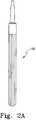
- FIG. 2Ais a plan view of a straight long bone distal stem implant in position in the canal prepared by the reamer of FIG. 1 for use with the present invention
- FIG. 3is a plan view of a sleeve for use on the distal long bone stem of FIG. 2 , according to an embodiment of the present invention
- FIG. 3Ais a plan view of a sleeve with a cylindrical bore and a cylindrical outer periphery according to another embodiment of the present invention.
- FIG. 3Bis a plan view of a sleeve with a cylindrical bore and a tapered outer periphery according to another embodiment of the present invention.
- FIG. 3Cis a partial plan view of a recess in the bore of a sleeve to mate with a protrusion on the distal long bone stem according to another embodiment of the present invention
- FIG. 3Dis an end view of the sleeve of FIG. 3C showing the recess in the bore of the sleeve;
- FIG. 3Eis an end view of a sleeve having three spaced apart recesses in the bore of the sleeve according to another embodiment of the present invention.
- FIG. 3Fis a partial plan view of a protrusion in the bore of the sleeve to mate with a recess on the distal long bone stem according to another embodiment of the present invention
- FIG. 3Gis an end view of the sleeve of FIG. 3F showing the protrusion in the bore of the sleeve;
- FIG. 3His an end view of a sleeve having three spaced apart protrusions in the bore of the sleeve according to another embodiment of the present invention.
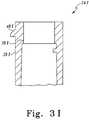
- FIG. 3Iis a plan view of a sleeve having a protrusion on the outer periphery of the sleeve according to another embodiment of the present invention.
- FIG. 3Jis an end view of the sleeve of FIG. 3I showing the protrusion on the periphery of the sleeve;
- FIG. 3Kis an end view of a sleeve having three spaced apart protrusions on the periphery of the sleeve according to another embodiment of the present invention.
- FIG. 3Lis an top view of a sleeve having a rib or ring on the periphery of the sleeve according to another embodiment of the present invention.
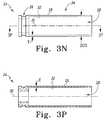
- FIG. 3Mis a plan view of a sleeve having a groove on the outer periphery of the sleeve according to another embodiment of the present invention.
- FIG. 3Nis a plan view of a sleeve having a groove on the outer periphery of the sleeve with a cylindrical bore and with a cylindrical outside diameter according to another embodiment of the present invention
- FIG. 3Pis a cross sectional view along the lines 3 P- 3 P in the direction of the arrows;
- FIG. 3Qis a plan view of the sleeve of FIG. 3N ;
- FIG. 4is a plan view of the distal implant stem of FIG. 2 with the sleeve of FIG. 3M installed on the stem, to form a distal implant sleeve assembly;
- FIG. 4Ais a plan view of a distal implant stem with an external protrusion for use with the sleeve of FIG. 3C installed on the stem, to form a distal implant sleeve assembly according to another embodiment of the present invention
- FIG. 4Bis an end view of the distal implant sleeve assembly of FIG. 4A showing the protrusion on the periphery of the distal implant stem;
- FIG. 4Cis an end view of a distal implant stem with 3 spaced apart external protrusions for use with the sleeve of FIG. 3E installed on the stem, to form a distal implant sleeve assembly according to another embodiment of the present invention
- FIG. 4Dis a plan view of a distal implant stem with an external indent for use with the sleeve of FIG. 3F installed on the stem, to form a distal implant sleeve assembly according to another embodiment of the present invention
- FIG. 4Eis an end view of the distal implant sleeve assembly of FIG. 4D showing the protrusion on the external indent of the distal implant stem;
- FIG. 4Fis an end view of a distal implant stem with 3 spaced apart external indents for use with the sleeve of FIG. 3H installed on the stem, to form a distal implant sleeve assembly according to another embodiment of the present invention
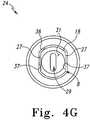
- FIG. 4Gis a top view of the implant/sleeve assembly of FIG. 4 ;
- FIG. 4His a plan view of a guide pin for use with the assembly of FIG. 4 to protect the sleeve of FIG. 3 ;
- FIG. 4Iis a plan view of a implant/sleeve/pin assembly with the guide pin of FIG. 4H assembled onto the implant/sleeve assembly of FIG. 4 ;
- FIG. 5is a plan view of a reamer for use with the implant/sleeve/pin assembly of FIG. 4I according to another embodiment of the present invention
- FIG. 5Ais a plan view of a reamer for use with a distal stem component having a cylindrical outer periphery, the reamer having a cylindrical opening an a cylindrical periphery according to another embodiment of the present invention
- FIG. 5Bis a plan view of a reamer for use with a distal stem component having a cylindrical outer periphery, the reamer having a cylindrical opening and a tapered periphery according to another embodiment of the present invention
- FIG. 5Cis a plan view of a reamer for use with a distal stem component according to another embodiment of the present invention.
- FIG. 6is a plan view of the reamer of FIG. 5 , partially in cross section;
- FIG. 6Ais a plan view of the reamer of FIG. 5C , partially in cross section;
- FIG. 7is a plan view, partially in cross section, of the reamer of FIG. 5C shown in greater detail;
- FIG. 7Ais a partial plan view of FIG. 7A showing the spring loaded detent positioned in the bore of the reamer to mate with a groove on the external periphery of the sleeve in greater detail;
- FIG. 7Bis a partial plan view of a proximal reamer showing a protrusion positioned in the bore of the reamer to mate with a groove on the sleeve according to another embodiment of the present invention
- FIG. 7Cis an end view of the proximal reamer of FIG. 7B showing the protrusion positioned in the bore of the reamer;
- FIG. 7Dis an end view of a proximal reamer of FIG. 7B showing 3 spaced apart protrusions positioned in the bore of the reamer according to another embodiment of the present invention
- FIG. 7Eis a partial plan view of a proximal reamer showing a ring positioned in the bore of the reamer to mate with a groove on the sleeve according to another embodiment of the present invention
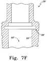
- FIG. 7Fis a partial plan view of a proximal reamer showing a groove positioned in the bore of the reamer to mate with a protrusion on the sleeve according to another embodiment of the present invention
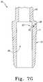
- FIG. 7Gis a plan view, partially in cross section, of the reamer of FIG. 5 shown in greater detail;
- FIG. 8is a plan view partially in cross section of the reamer of FIG. 5 in position on the distal implant/sleeve assembly of FIG. 4 ;
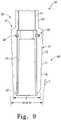
- FIG. 9is a partial plan view, partially in cross section, of the reamer of FIG. 5 with the sleeve of FIG. 3 in position on the reamer of FIG. 5 to form a reamer/sleeve assembly according to another embodiment of the present invention
- FIG. 10is a proximal body implant for use with the distal stem implant of FIG. 2 ;
- FIG. 11is a long bone implant assembly including the proximal body implant of FIG. 10 in position on the long bone distal stem implant of FIG. 2 ;
- FIG. 12is an enlarged partial plan view of the long bone implant assembly of FIG. 11 showing the tapered connection in greater detail;
- FIG. 13is an exploded view of the long bone implant assembly of FIG. 11 including a head
- FIG. 14is an assembled view of the long bone implant assembly of FIG. 13 ; in position in the body;
- FIG. 15is a proximal trial component for use with the long bone distal stem implant of FIG. 2 ;
- FIG. 16is a kit for use in performing arthroplasty according to another embodiment of the present invention.
- FIG. 17is a flow chart of a surgical procedure according to another embodiment of the present invention.
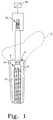
- the femur 2includes an intermedullary canal 4 into which the prosthesis of the present invention may be inserted.
- the femur 2is resected along resection line 6 by, for example, a power tool, for example, a saw.
- the resecting of the long bone or femur 2exposes the intermedullary canal 4 of femur 2 .
- a reamer 8that may be a standard commercially available reamer is positioned in the intermedullary canal 4 of the long bone 2 to form cavity 10 for receiving an orthopedic joint implant.
- the reamer 8includes a plurality of longitudinally extending flutes 12 which are used to remove bone and other biological matter from the intermedullary canal 4 to form the cavity 10 .
- the reamer 8may be rotated by use of a connector 14 positioned on the reamer 8 .
- the connector 14may be any standard connector for example a Hudson or an A-O connector.
- the connector 14is used to connect to a power tool 16 for rotating the reamer 8 .
- the power tool 16may be any standard power tool. It should be appreciated that the reamer 8 may be rotated through the use of the connector 14 by a hand tool for example a “T” shaped handle.
- a distal implant stem 18is shown fitted into the cavity 10 formed in the intermedullary canal 4 of the long bone or femur 2 .
- the distal implant stem 18may, as is shown in FIG. 2 , be in the form of a curved or bent stem.
- the natural femurhas a curve that may best be replicated in an implant component, particularly when the distal implant stem has a particularly long length, such as is used in a revision arthroplasty.
- the distal implant stem shapemay be defined by a radius R extending from origin 21 .
- the curved or bent portion of stem 18may be located mostly distally on the stem 18 .
- the distal implant stemincludes an external tapered proximal portion 20 and a connector in the form of external threads 24 located proximally from the tapered proximal portion 20 .
- the resection line 6may generally correspond to the position at which the stem 18 , when implanted, begins the external tapered portion 20 of the stem 18 .
- the stemmay be in the form of a straight or cylindrical stem 18 A which does not include a curved or bent portion.
- the use of the proximal reamer in the present invention with such a cylindrical stem 18 Amay provide for bone removal for receiving the proximal body that is precise and that minimizes bone removal in comparison with other methods of removing bone for receiving the proximal body.
- a sleeve 24 X for use with distal implant stemsfor example stem 18 of FIG. 2 .
- the sleeve 24 Xis used with a proximal reamer 58 C (See FIG. 5C ).
- the sleeve 24 Xas shown in FIG. 3 , is fitable over the tapered proximal portion 20 of the distal implant stem 18 .
- the sleeve 24 Xdefines an outer periphery 26 X of the sleeve 24 X. As shown in FIG.
- the sleeve 24 Xmay be hollow and may include a cavity 28 X extending longitudinally along sleeve center line 30 X.
- the cavity 28 Xmay define an inner periphery 32 X of the sleeve 24 X.
- the inner periphery 32 X of the sleeve 24 Xmay have any shape that mates with external periphery 19 of the tapered proximal portion 20 of the stem 18 (See FIG. 2 ).
- the stem 18includes the tapered proximal portion 20 as well as the threaded portion 22 .
- the inner periphery 32 Xincludes tapered portion 34 X to mate with tapered portion 20 of the stem 18 .
- the inner periphery 32 X of the sleeve 24 Xincludes a threaded cylindrical portion 36 X which mates with internal threads 25 formed on the stem 18 (See FIG. 2 ).
- the tapered portion 34 X and the cylindrical portion 36 Xdefine a step or shoulder 38 X positioned between the cylindrical portion 36 X and the tapered portion 34 X of the sleeve 24 X.
- the sleeve 24 Xmay include the outer periphery 26 X having a shape compatible to that of the proximal reamer (See FIG. 5C ).
- the outer periphery 26 Xmay, as is shown in FIG. 3 , be tapered and defined by an included angle ⁇ .
- the included angle ⁇may be designed such that the sleeve 24 X may have a wall thickness T which is generally uniform.
- the tapered portion 34 X of the internal periphery 32 X of the sleeve 24 Xmay be defined by and include an included angle ⁇ which is similar to the included angle ⁇ . As shown in FIG. 3 , the internal angle ⁇ is slightly smaller than the included angle ⁇ .
- the sleeve 24 Xis fixedly secured to stem 18 of FIG. 2 so that wear or damage does not occur to the tapered proximal portion 20 of the stem 18 .
- the sleeve 24 Xmay include a feature for assuring that the stem 18 is fixedly secured to the sleeve 24 X when assembled together.
- the angle ⁇ of the internal periphery at the tapered portion 34 Xmay be designed such that it provides for a locking taper with the tapered portion 20 of the stem 18 .
- cylindrical portion 36 X of the inner periphery 32 Xmay include a feature of, for example, internal threads 40 X show in phantom, which may alternatively be used to thread the sleeve 24 X into engagement with external threads 23 on the stem 18 .
- Sleeve 24 Ais like sleeve 24 of FIG. 3 except that sleeve 24 A includes an outer periphery 26 A and an inner periphery 32 A that are both cylindrical.
- the sleeve 24 Ais suitable for use with reamers having a cylindrical profiled driving surface.
- sleeve 24 Bis similar to the sleeve 24 of FIG. 3 except that the sleeve 24 B includes an outer periphery 26 B which is cylindrical and an inner periphery 32 B which is tapered. It should be appreciated that the sleeve 24 B of FIG. 3B may have a uniform configuration of the inner periphery 32 B with no step or shoulder, as well as, a simple cylindrical shape of outer periphery 26 B.
- the sleeve 24may include an annular external ring or lip 42 which extends outwardly from outer periphery 26 at lower end 44 of the sleeve 24 .
- the lip 42may serve to prevent the outer periphery 26 of the sleeve 24 to be permanently taper locked onto the proximal reamer.
- the sleeve 24While it is desirable to have the sleeve 24 be rigidly fixed to the distal implant 18 when the proximal reamer is used with the sleeve 24 , such rigid engagement of the sleeve 24 to the implant stem 18 may be acquired by an interference fit between the inner periphery 32 of the sleeve 24 and the tapered external portion 20 of the stem 18 if the components are cylindrical or tapered locked if not.
- the sleeve 24may include a locking or securing feature 46 that cooperates with a connection feature 56 on the stem 18 to assure the rigidity of the sleeve 24 against the stem 18 .
- a sleeve 24 Cis shown which is similar to the sleeve 24 of FIG. 3 except that the sleeve 24 C includes the sleeve/stem securing feature 46 C in the form of an indentation.
- the indentation 46 Cmay mate with a complimentary protrusion extending from the outer periphery 26 of the external tapered portion 20 of the stem 18 (see FIG. 2 ).
- the sleeve 24 Cmay include a solitary indent 46 C as shown in FIG. 3D .
- Sleeve 24 Eis like sleeve 24 C of FIGS. 3C and 3D except that the sleeve 24 E includes more than one indent, for example, three spaced apart indents 46 E.
- Sleeve 24 Fis similar to sleeve 24 of FIG. 3 except that the sleeve 24 F includes a sleeve/stem securing feature in the form of a protrusion 46 F extending inwardly from inner periphery 32 F of the sleeve 24 F.
- the protrusion 46 Fis a solitary protrusion.
- the protrusion 46 F of FIGS. 3F and 3Gmay mate with an indent 56 F formed on the external tapered portion 20 F of the stem 18 F of FIG. 4F .
- sleeve 24 Hyet another embodiment of the present invention is shown as sleeve 24 H.
- the sleeve 24 His like the sleeve 24 F except that the sleeve 24 H includes three spaced apart protrusions 46 H.
- sleeve 24 Iyet another embodiment of the present invention is shown as sleeve 24 I.
- the sleeve 24 Iis similar to sleeve 24 of FIG. 3 except that the sleeve 24 I includes a sleeve/proximal reamer securing feature in the form of a protrusion 48 I positioned near shoulder 38 I of the sleeve 24 .
- the protrusion 48 Iextends outwardly from outer periphery 26 I of the sleeve 24 I.
- the protrusion 48 Iserves to mate with an indent on the proximal reamer so that when the proximal reamer is extracted from the stem 18 , the sleeve 24 I remains with the proximal reamer and does not need to be separately removed from the stem 18 (see FIG. 2 ).
- the protrusion 48 Imay have any suitable shape and may as shown in FIG. 3I be tapered downwardly to make the engagement of the protrusion into the opening easier in the downward direction of the reamer and to assure that the sleeve 24 is removed with the proximal reamer. This feature reduces surgical procedure steps and saves time in the operating room.
- the protrusion 48 I of the sleeve 24 Imay be a solitary protrusion.
- sleeve 24 Kyet another embodiment of the present invention is shown as sleeve 24 K.
- the sleeve 24 Kincludes a protrusion 48 K extending outwardly from external periphery 26 K of the sleeve 24 K. It should be appreciated as shown in FIG. 3K that three separate spaced apart protrusions 48 K may be utilized with complimentary indents formed in the proximal reamer (see FIG. 4 ).
- the protrusion 48 I of the sleeve 24 Imay be a solitary protrusion that extends around the periphery of the sleeve to form a ring or lip.
- the sleeve 24 Xmay include a sleeve reamer connection feature 48 X in the form of an internal groove 48 X extending inwardly from outer periphery 26 X of the sleeve 24 X.
- the groove 48 Xmay be positioned anywhere along longitudinal axis central line 30 X of the sleeve 24 X, but preferably is located near the shoulder 38 X of the sleeve 24 X.
- the groove 48 Xserves to mate with a detent 88 C formed in the proximal reamer 58 C (See FIG. 7A ). It should be appreciated that the feature 48 X should provide for an ability to have relative rotation between the sleeve 24 X and the proximal reamer 58 C.
- a sleeve 24 for use with distal implant stemsfor example stem 18 of FIG. 2
- the sleeve 24is used with a proximal reamer 58 (See FIG. 5 ).
- the sleeve 24as shown in FIG. 3 , is fitable over the tapered proximal portion 20 of the distal implant stem 18 .
- the sleeve 24defines an outer periphery 26 of the sleeve 24 .
- the sleeve 24may be hollow and may include a cavity 28 extending longitudinally along sleeve center line 30 .
- the cavity 28may define an inner periphery 32 of the sleeve 24 .
- the inner periphery 32 of the sleeve 24may have any shape that mates with external periphery 19 of the tapered proximal portion 20 of the stem 18 .
- the inner periphery 19may be cylindrical and interferencely fit onto the tapered proximal portion 20 of the stem 18 of FIG. 2 .
- the stem 18includes the tapered proximal portion 20 as well as the threaded portion 22 .
- the inner periphery 32includes a distal cylindrical portion 34 to interferencely fit with tapered portion 20 of the stem 18 .
- the inner periphery 32 of the sleeve 24includes a proximal cylindrical portion 36 with opposed double flats 37 which mates with opposed double flats 27 formed on the stem 18 (See FIG. 2 ).
- the sleeve 24may include the outer periphery 26 having a shape compatible to that of the proximal reamer (See FIG. 5 ). If the angle of the proximal reamer bore is small enough, the outer periphery 26 of the sleeve 24 may be cylindrical. The outer periphery 26 may, as is shown in FIG. 3 , be cylindrical and defined by diameter DOS. The sleeve 24 may have a wall thickness T which is generally uniform. Thus distal cylindrical portion 34 of the internal periphery 32 of the sleeve 24 may be defined by wall thickness T.
- the sleeve 24is fixedly secured to stem 18 so that wear or damage does not occur to the tapered proximal portion 20 of the stem 18 .
- the sleeve 24may include a feature for assuring that the stem 18 is fixedly secured to the sleeve 24 when assembled together.
- the distal cylindrical portion 34 of the internal periphery 32 of the sleeve 24may be designed such that it provides for an interference fit with the tapered portion 20 of the stem 18 .
- the cylindrical portion 36 of the inner periphery 32may include a feature of, for example, internal threads (not shown), which may alternatively be used to thread the sleeve 24 into engagement with external threads 23 on the stem 18 .
- the sleevemay optionally have longitudinal slots (not shown) through the wall of the sleeve 24 .
- the slotmay be a single slot or a plurality of spaced apart slots.
- the slotsmay partially extend along the length of the sleeve 24 or may extend the fill length, splitting the sleeve 24 .
- the slotspermit additional interference fit.
- the implant sleeve assembly 50includes the sleeve 24 of FIG. 3 positioned on the orthopedic implant stem 18 of FIG. 2 .
- the orthopedic implant stem 18is positioned in canal 4 of cavity 10 of soft or cancellous bone in the canal 4 of the femur 2 .
- the sleeve 24may be loaded onto the orthopedic implant stem 18 in the direction of arrow 52 .
- the orthopedic implant stem 18may be moved from loading position 54 as shown in phantom to the installed position 56 as shown in solid.
- the sleeve 24may be installed in situa on the orthopedic implant stem 18 already installed into the canal 4 of the cavity 10 of the femur 2 , it should be appreciated that the sleeve 24 may be preinstalled onto the orthopedic implant stem 18 prior to the performing of the surgery such that the sleeve 24 may protect external periphery 19 of the stem tapered portion 20 of the stem 18 during shipment and during the installation of the stem 18 into the cavity 10 of the canal 4 of the femur 2 .
- the sleeve 24is preferably rigidly fitted against the orthopedic implant stem 18 .
- the rigid connection of the sleeve 24 to the stem 18may be accomplished by the fitting of the sleeve internal periphery 32 of the sleeve 24 against the external periphery 19 of the stem tapered portion 20 of the stem 18 .
- the internal periphery 32 of the sleeve 24may be cylindrical and may thus interferencely fit with the external periphery 19 of the stem tapered portion 20 of the orthopedic implant stem 18 defined by included angle ⁇ .
- the orthopedic implant stem 18may include features to assure the rigid securement of the sleeve 24 to the stem 18 .
- the stem 18may include a stem/sleeve connection feature 56 in the form of an interference fit for cooperation with the sleeve 24 (See FIG. 3 ).
- implant sleeve assembly 50 Ais similar to the implant sleeve assembly 50 of FIG. 4 , except that the implant sleeve assembly 50 A includes a stem 18 A which has a stem/sleeve connection feature in the form of a protrusion 56 A extending from the stem 18 A.
- the protrusion 56 Afits into the single indentation 46 C formed in the sleeve 24 C of FIGS. 3C and 3D .
- implant/sleeve assembly 50 Cyet another embodiment of the present invention is shown as implant/sleeve assembly 50 C.
- the implant sleeve assembly 50 Cis similar to the implant/sleeve assembly 50 A of FIGS. 4A and 4B except that stem 18 of the implant sleeve assembly 50 C includes a plurality of spaced apart protrusions 56 C extending from stem 18 C.
- the protrusions 56 Ccooperate with a plurality of indents 46 E formed on sleeve 24 E.
- implant sleeve assembly 50 Dincludes a solitary indent 56 D formed on the stem 18 D.
- the indent 56 D on the stem 18 Dcooperates with a solitary protrusion 46 F formed on sleeve 24 F of FIGS. 3F and 3G .
- implant sleeve assembly 50 Fis similar to the implant sleeve assembly 50 D of FIGS. 4E and 4D .
- the implant sleeve assembly 50 Fincludes a stem 18 F which includes three spaced apart indentations 56 F.
- the indentations 56 F of the stem 18 Fcooperate with three spaced apart protrusions 46 H formed on sleeve 24 H of FIG. 3H .
- the stem 18 of the distal reamer 8includes opposed double flats 27 formed on stem 18 .
- the proximal cylindrical portion 36 of the sleeve 24includes opposed double flats 37 formed in the proximal cylindrical portion 36 of the sleeve 24 .
- the opposed double flats 37 formed in the proximal cylindrical portion 36 of the sleeve 24mate with the opposed double flats 27 formed on stem 18 .
- the stem 18 of the distal reamer 8also includes an elongated central recess 29 extending from end 31 of the stem 18 of the distal reamer 8 .
- the guide pin 33for use with the implant sleeve assembly 50 of FIG. 4 to protect the sleeve 18 of FIGS. 3N , 3 P and 3 Q.
- the guide pin 33fits onto the external threads 23 on the stem 18 of distal reamer 8 of FIG. 1 .
- the guide pin 33includes internal threads 35 for mating with the external threads 23 on the stem 18 of distal reamer 8 .
- the guide pin 33may have any shape for fitting into the proximal reamer 58 of FIG. 5 .
- the guide pin 33may have a generally cylindrical shape define by diameter DGP.
- the guide pin 33may have a rounded or bullet nose 43 to assist in guiding the reamer 58 onto the guide pin 33 .
- the guide pinmay include a through transverse opening- 51 for use in extracting the guide pin 33 .
- FIG. 4Ithe guide pin 33 of FIG. 4H is shown assembled onto the implant/sleeve assembly 50 of FIG. 4 to form an implant/sleeve/pin assembly 45 .
- the proximal reamer 58 of FIG. 5is guided onto the implant/sleeve/pin assembly 45 .
- reamer 58yet another embodiment of the present invention is shown as reamer 58 .
- the reamer 58is utilized for reaming a proximal portion 62 of the cavity 10 formed in the canal 4 of the femur 2 .
- the reamer 58is for use in implanting a joint prosthesis 62 .
- the joint prosthesis 62includes the distal stem portion 18 .
- the reamer 58includes a body 66 defining a distal cavity 68 formed in the body 66 .
- the distal cavity 68is adapted to receive at least a portion of the orthopedic implant component, for example, stem 18 .
- the reamer 58also includes a plurality of cutting edges 70 extending outwardly from the body 66 .
- the edges 70are adapted for cooperation with bone, for example, the femur 2 .
- the reamer 58further includes a stem 72 extending from an end 74 of the body 66 .
- the body 66may have any suitable shape and may for example, be cylindrical, have a polygon cross-section, or have a periphery 76 that is tapered.
- the stem 72may have any suitable shape and may include a connector 78 in the form of, for example, a standard commercially available connector, for example, a AO connector or an Hudson connector, capable of receiving a tool, for example, a driver 80 for rotating the reamer 58 in the direction of arrow 82 .
- the reamer 58includes cutting edges 70 that engage and remove bone.
- the reamer 58may have any suitable shape and may have any number of cutting edges 70 .
- the flutesare equally spaced and extend longitudinally along longitudinal center line 84 of the proximal reamer 58 .
- the flutes 70may run longitudinally with the longitudinal axis 84 or may as is shown in FIG. 5 be helical or form an angle, for example angle ⁇ with respect to the horizontal.
- the distal cavity 68 formed in the proximal reamer 58may have any suitable shape and may for example be cylindrical or have an external periphery 86 which defines a cone.
- the internal periphery 86 of the proximal reamer 58defines the distal cavity 68 and, preferably, has a shape that mates with the proximal portion 20 of the stem 18 .
- external periphery 71 of reamer 58is defined by cutting edges 70 and may be tapered.
- the internal periphery 86 formed by the distal cavity 68may also be tapered. It should be appreciated that other shapes of these components maybe within the scope of the invention.
- the reamer 58includes a proximal internal cavity 39 for receiving the guide pin 33 of FIG. 4H .
- the proximal internal cavity 39defines an end 41 of the internal cavity that provides a stop for cooperation with the bullet nose 43 of the guide pin 33 .
- the reamer 58may also include longitudinal slots 47 extending from the outer periphery 49 of the reamer to the proximal internal cavity 39 for viewing the insertion of the guide pin 33 into the reamer 58 and to ease cleaning of the reamer 58 .
- the reamer 58may have a solitary or multiple (for example 3 equally spaced apart) slots 47 .
- proximal reamer 58 Ais similar to the proximal reamer 58 of FIG. 5 except that the proximal reamer 58 A includes cutting edges 70 A that form an external periphery 71 A that is cylindrical. Also, cavity 68 A forms an internal periphery 86 A which is, likewise, cylindrical.
- reamer 58 Byet another embodiment of the present invention is shown as reamer 58 B.
- the reamer 58 Bis similar to the reamer 58 of FIG. 5 except that the reamer 58 B includes a cavity 68 B which forms an interior periphery 86 B which is cylindrical.
- Cutting edges 70 Bform an external periphery 71 B which is tapered or conical.
- the external periphery 71 Bis defined by included angle ⁇ .
- reamer 58 Cyet another embodiment of the present invention is shown as reamer 58 C.
- the reamer 58 Cis utilized for reaming a proximal portion 62 C of the cavity 10 formed in the canal 4 of the femur 2 .
- the reamer 58 Cis for use in implanting a joint prosthesis 62 .
- the joint prosthesis 62includes the distal stem portion 18 .
- the reamer 58 Cincludes a body 66 C defining a cavity 68 C formed in the body 66 C.
- the cavity 68 Cis adapted to receive at least a portion of the orthopedic implant component, for example, stem 18 .
- the reamer 58 Calso includes a plurality of cutting edges 70 C extending outwardly from the body 66 C.
- the edges 70 Care adapted for cooperation with bone, for example, the femur 2 .
- the reamer 58 Cfurther includes a stem 72 C extending from an end 74 C of the body 66 C.
- the body 66 Cmay have any suitable shape and may for example, be cylindrical, have a polygon cross-section, or have a periphery 76 C that is tapered.
- the stem 72 Cmay have any suitable shape and may include a connector 78 C in the form of, for example, a standard commercially available connector, for example, a AO connector or an Hudson connector, capable of receiving a tool, for example, a driver 80 C for rotating the reamer 58 C in the direction of arrow 82 C.
- the reamer 58 Cincludes cutting edges 70 C that engage and remove bone.
- the reamer 58 Cmay have any suitable shape and may have any number of cutting edges 70 C.
- the flutesare equally spaced and extend longitudinally along longitudinal center line 84 C of the proximal reamer 58 C.
- the flutes 70 Cmay run longitudinally with the longitudinal axis 84 C or may as is shown in FIG. 5C be helical or form an angle, for example angle ⁇ with respect to the horizontal.
- the cavity 68 C formed in the proximal reamer 58 Cmay have any suitable shape and may for example be cylindrical or have an external periphery 86 C which defines a cone.
- the internal periphery 86 C of the proximal reamer 58 Cdefines the distal cavity 68 and, preferably, has a shape that mates with the proximal portion 20 of the stem 18 .
- external periphery 71 C of reamer 58 Cis defined by cutting edges 70 C and may be tapered.
- the internal periphery 86 C formed by the cavity 68 Cmay also be tapered. It should be appreciated that other shapes of these components maybe within the scope of the invention.
- the cutting edge 70 of the reamer 58may have any suitable form.
- the cutting edge 70may include a plurality of spaced apart flutes 73 .
- Each of the flutes 73may as shown in FIG. 6 include a grouping of spaced apart reliefs 75 .
- the reliefsmay be positioned on each of the flutes 73 and may form circular rings or as shown in FIG. 6 be spirally positioned around the reamer external periphery 71 .
- the reamer 58may include an attachment feature 88 for cooperation with the sleeve 24 such that the sleeve 24 is removed with the reamer 58 when the reamer has completed preparing the cavity for the proximal body.
- the attachment feature 88may have any suitable size and shape to assist in having the sleeve 24 be removed with the reamer 58 .
- the cutting edge 70 C of the reamer 58 Cmay have any suitable form.
- the cutting edge 70 Cmay include a plurality of spaced apart flutes 73 C.
- Each of the flutes 73 Cmay as shown in FIG. 6C include a grouping of spaced apart reliefs 75 C.
- the reliefsmay be positioned on each of the flutes 73 C and may form circular rings or as shown in FIG. 6C be spirally positioned around the reamer external periphery 71 C.
- the reamer 58 Cmay include an attachment feature 88 C for cooperation with the sleeve 24 X of FIG. 3 such that the sleeve 24 X is removed with the reamer 58 C when the reamer has completed preparing the cavity for the proximal body.
- the attachment feature 88 Cmay have any suitable size and shape to assist in having the sleeve 24 X be removed with the reamer 58 C.
- the attachment feature 88 Cis shown in greater detail.
- the attachment feature 88 Cmay be in the form of a protrusion or as shown in FIG. 7 be in the form of a spring loaded detent.
- the spring loaded detent 88 C of the reamer 58 Cis shown in greater detail.
- the spring loaded detent 88 Cincludes a ball 83 C which is spring biased in the direction of the cavity 68 C.
- the spring 85 C and detent 88 Care positioned in an opening 87 C.
- the detent 88 Creceives the sleeve 24 C by compressing the spring 85 C and moving the ball 83 C inwardly.
- the spring 85 Cthen extends to engage the groove 48 C in the sleeve 24 C so that the sleeve 24 C may be removed with the reamer 58 C.
- the ball 83 C of the detent 88 Ccooperates with groove 48 C of the sleeve 58 C as shown in FIG. 3M .
- the detent 88 CBy providing the detent 88 C to fit with a groove, for example groove 48 M of FIG. 3M , the reamer 58 C may rotate while the sleeve 24 X is stationary or fixed to the distal stem 18 .
- Reamer 58 Bis similar to the reamer 58 of FIG. 7 except that the reamer 58 B has a fixed solitary protrusion 88 B which extends inwardly from internal periphery 86 B of the cavity 68 B of the reamer 58 B.
- the protrusion 88 B of reamer 58 Bcooperates with groove 48 of the sleeve 58 , as shown in FIG. 3M .
- reamer 58 Dis similar to the reamer 58 B of FIGS. 7B and 7C except that the reamer 58 D includes three spaced apart protrusions 86 D extending inwardly from internal periphery 86 D of the cavity 68 D of the reamer 58 D.
- the protrusion 88 D of reamer 58 Dcooperates with groove 48 of the sleeve 58 , as shown in FIG. 3M .
- the protrusion 88 B of FIGS. 7B and 7C as well the protrusions 88 D of the reamer 58 D of FIG. 7Dcooperate with a sleeve having a groove, for example sleeve 24 having groove 48 , as shown in FIG. 3M .
- the protrusions and the groovecooperate such that the proximal reamer 58 may rotate while the stem 18 and the sleeve 24 are stationary.
- proximal reamer 58 Eyet another embodiment of the present invention is shown as proximal reamer 58 E.
- the proximal reamer 58 Eis similar to the reamer 58 D of FIG. 7D except that a continuous rib 88 E extends inwardly from internal periphery 86 E of cavity 68 E.
- the rib 88 Ecooperates with groove 48 formed in sleeve 24 as shown in FIG. 3M .
- reamer 58 Fyet another embodiment of the present invention is shown as reamer 58 F.
- the reamer 58 Fis similar to the reamer 58 E as shown in FIG. 7E except that the reamer 58 F includes a circumferential interior groove 88 F extending outwardly from internal periphery 86 F formed in cavity 68 F of the reamer 58 F.
- the groove 88 Fcooperates with, for example, the single protrusion 24 A of FIG. 3K or the rib 48 K formed in sleeve 24 K of FIG. 3K .
- the attachment feature 88is shown in greater detail.
- the attachment feature 88may be in the form of a protrusion or as shown in FIG. 7 be in the form of a spring loaded detent.
- the spring loaded detent 88includes a ball 83 which is spring biased in the direction of the distal cavity 68 .
- the spring 85 and detent 88are positioned in an opening 87 .
- the detent 88receives the sleeve 24 by compressing the spring 85 and moving the ball 83 inwardly.
- the spring 85then extends to engage the groove 48 in the sleeve 24 so that the sleeve 24 may be removed with the reamer 58 .
- the ball 83 of the detent 88cooperates with groove 48 of the sleeve 58 as shown in FIG. 3N .
- the reamer 58may rotate while the sleeve 24 is stationary or fixed to the distal stem 18 .
- reamer assembly 90is shown.
- the sleeve 24 and the guide pin 33are positioned in the proximal internal cavity 39 formed in the proximal reamer 58 .
- the orthopedic implant stem 18is positioned in the distal cavity 68 of the reamer 58 and the external periphery 19 of the proximal portion 20 of the stem 18 mates with the inner periphery 32 of the sleeve 24 .
- the sleeve outer periphery 26is rotatably engaged with internal periphery 86 of the reamer 58 .
- the securing feature 48 of the sleeve 24engages with the attachment feature 88 of the reamer 58 .
- the securing feature 56 of the stem 18connects with the locking feature 46 of the sleeve 24 .
- the reamer sleeve assembly 92includes the reamer 58 as well as the sleeve 24 . As shown in FIG. 9 , the reamer sleeve assembly includes a detent 88 formed on the reamer 58 which cooperates with groove 48 formed in the sleeve 24 .
- the outer periphery 71 defined by the cutting edge 70 of the reamer 58is utilized to remove bone from proximal portion 89 of the femur 2 .
- Cutting edges 70 of the reamer 58prepare cavity 91 in the proximal portion 89 of the femur 2 .
- the proximal cavity 91is defined by angle ⁇ which is generally similar to the angle ⁇ defined by the external periphery 71 of the reamer 58 .
- the lip 42 of the sleeve 24cooperates with the groove 48 formed in the sleeve 24 and the D-tent 88 to securably position the sleeve 24 in the reamer 58 .
- the orthopedic implant proximal component 90is shown for use with the stem 18 .
- the orthopedic implant proximal component 90includes a body 93 for receiving head 96 of the prosthesis.
- the body 93defines a longitudinal opening 97 for receiving the stem 18 .
- the body 93further defines an external portion 98 which is sized to fit within the opening 91 prepared in the proximal portion 89 of the femur 2 by the reamer 58 (See FIG. 9 ).
- the hip stem assembly 99includes distal implant stem 18 to which proximal body 93 is fixedly secured.
- the tapered portion 20 of the stem 18is fitted into longitudinal opening 97 formed in body 93 of the proximal component 92 .
- the tapered portion 20 of the stem 18may include external threads 21 formed on threaded portion 22 of the stem 18 .
- a fastener in the form of a nut 100may be used to assure the complete seating of the tapered portion 20 of the stem 18 into the longitudinal opening 97 .
- the nut 100may be left on the orthopedic stem assembly 99 or may be removed once the stem 18 is securely fitted to the proximal component 92 .
- the proximal component 92is shown in greater detail. As shown in FIG. 12 , the proximal portion 20 of the distal component 18 is shown fitted into longitudinal opening 97 of the proximal component 92 . The threads 21 of the threaded portion 22 of the stem 18 engage the nut 100 and draw the stem into engagement with the proximal component 92 . External periphery 98 of the proximal component 92 is fitted into cavity 91 formed by the proximal reamer 58 . The neck 94 supports an externally tapered periphery 95 to which head 96 in the form of a spherical ball is securely fitted.
- the components of the stem assembly 99are shown in an exploded view.
- the stem 18 , the proximal component 92 , the head 96 , and the nut 100are shown in their respective position prior to assembly.
- the stem 18has an arcuate shape.
- the present inventionis particularly well suited for use with orthopedic implants with a curved or bent stem. It should be appreciated however that the current invention may be used with straight or cylindrical or linear stems as well.
- a reamercan not be provided for preparing simultaneously the distal cavity for the distal reamer and a closely fitting reamed portion for the proximal body as these two components do not have a common center line and thus can not be reamed simultaneously.
- the hip prosthesis 102includes the stem assembly 99 as well as head 96 .
- a shell or cup 104may be secured onto acetabulum 106 .
- the cup or shell 104may mate directly with the head 96 or a liner or bearing 108 may be positioned between the cup 104 and the head 96 .
- the orthopedic implant 102may be made of any suitable material.
- the stem 99may be made of any suitable durable material that is compatible with the human anatomy and may for example be made of a metal. If made of a metal, the orthopedic implant components may be made of, for example, cobalt chromium alloy, stainless steel alloy, or a titanium alloy.
- the liner or bearing 108may be made of a metal or may be made of a plastic, for example, polyethylene.
- a trial neck 110is shown for use with the distal implant stem 18 .
- the trial neck 110substitutes for the proximal component 92 and may be utilized to provide a trial reduction to assure that the proper proximal component is used.
- a proximal implant similar to the trial neck 110will be substituted once the trial reduction has been performed and the proximal trial neck 110 is found to be suitable, thus making the corresponding proximal component suitable for the patient.
- the kit 112for use in performing arthroplasty is provided.
- the kit 112includes proximal reamer 58 , as well as, sleeve 24 and distal implant stem 18 .
- the kit 112may further include a distal reamer 8 .
- the kit 112may further include a proximal trial 110 .
- the kit 112may further include proximal implant component 92 .
- the kit 112may further include guide pin 33 .
- a method 220 for performing arthroplastyincludes a first step 222 of resecting an end portion of a long bone.
- the method 220further includes a second step 224 of preparing a central longitudinal opening in a medullary canal of the long bone.
- the method 220further includes a third step 226 of providing a prosthetic stem component and a fourth step 228 of installing the prosthetic stem component into the opening in the medullary canal.
- the method 220further includes a fifth step 230 of providing a reamer including an opening for receiving the prosthetic stem component and a sixth step 232 of positioning the reamer onto prosthetic stem component with the opening of the reamer positioned at least partially over the prosthetic stem component.
- the method 220further includes an seventh step 234 of reaming a portion of the long bone with the reamer and a ninth step 236 of removing the reamer.
- the method 220further includes a ninth step 238 of installing a prosthetic body component onto the prosthetic stem component.
Landscapes
- Health & Medical Sciences (AREA)
- Life Sciences & Earth Sciences (AREA)
- Orthopedic Medicine & Surgery (AREA)
- Surgery (AREA)
- Animal Behavior & Ethology (AREA)
- Public Health (AREA)
- Oral & Maxillofacial Surgery (AREA)
- Engineering & Computer Science (AREA)
- Biomedical Technology (AREA)
- Heart & Thoracic Surgery (AREA)
- Veterinary Medicine (AREA)
- General Health & Medical Sciences (AREA)
- Transplantation (AREA)
- Nuclear Medicine, Radiotherapy & Molecular Imaging (AREA)
- Medical Informatics (AREA)
- Dentistry (AREA)
- Molecular Biology (AREA)
- Cardiology (AREA)
- Vascular Medicine (AREA)
- Physical Education & Sports Medicine (AREA)
- Biophysics (AREA)
- Surgical Instruments (AREA)
- Prostheses (AREA)
- Dental Tools And Instruments Or Auxiliary Dental Instruments (AREA)
- Control And Other Processes For Unpacking Of Materials (AREA)
- Milling Processes (AREA)
Abstract
Description
Claims (4)
Priority Applications (11)
| Application Number | Priority Date | Filing Date | Title |
|---|---|---|---|
| US11/529,799US8597298B2 (en) | 2006-09-29 | 2006-09-29 | Proximal reamer |
| EP07253847AEP1905394B1 (en) | 2006-09-29 | 2007-09-27 | Proximal reamer |
| DE602007010219TDE602007010219D1 (en) | 2006-09-29 | 2007-09-27 | Proximal milling tool |
| AT07253847TATE486548T1 (en) | 2006-09-29 | 2007-09-27 | PROXIMAL MILLING TOOL |
| EP10170706.5AEP2241293B1 (en) | 2006-09-29 | 2007-09-27 | Sleeve for proximal reamer |
| JP2007254157AJP5265164B2 (en) | 2006-09-29 | 2007-09-28 | Proximal reamer |
| CN201610096156.3ACN105640676B (en) | 2006-09-29 | 2007-09-29 | proximal reamer |
| CN200710170103.2ACN101152101B (en) | 2006-09-29 | 2007-09-29 | Proximal reamer |
| JP2012180081AJP5539467B2 (en) | 2006-09-29 | 2012-08-15 | Proximal reamer |
| US13/826,841US8852189B2 (en) | 2006-09-29 | 2013-03-14 | Proximal reamer |
| US13/826,259US8852188B2 (en) | 2006-09-29 | 2013-03-14 | Proximal reamer |
Applications Claiming Priority (1)
| Application Number | Priority Date | Filing Date | Title |
|---|---|---|---|
| US11/529,799US8597298B2 (en) | 2006-09-29 | 2006-09-29 | Proximal reamer |
Related Child Applications (2)
| Application Number | Title | Priority Date | Filing Date |
|---|---|---|---|
| US13/826,841DivisionUS8852189B2 (en) | 2006-09-29 | 2013-03-14 | Proximal reamer |
| US13/826,259DivisionUS8852188B2 (en) | 2006-09-29 | 2013-03-14 | Proximal reamer |
Publications (2)
| Publication Number | Publication Date |
|---|---|
| US20080161811A1 US20080161811A1 (en) | 2008-07-03 |
| US8597298B2true US8597298B2 (en) | 2013-12-03 |
Family
ID=38878350
Family Applications (3)
| Application Number | Title | Priority Date | Filing Date |
|---|---|---|---|
| US11/529,799Active2031-07-31US8597298B2 (en) | 2006-09-29 | 2006-09-29 | Proximal reamer |
| US13/826,841ActiveUS8852189B2 (en) | 2006-09-29 | 2013-03-14 | Proximal reamer |
| US13/826,259ActiveUS8852188B2 (en) | 2006-09-29 | 2013-03-14 | Proximal reamer |
Family Applications After (2)
| Application Number | Title | Priority Date | Filing Date |
|---|---|---|---|
| US13/826,841ActiveUS8852189B2 (en) | 2006-09-29 | 2013-03-14 | Proximal reamer |
| US13/826,259ActiveUS8852188B2 (en) | 2006-09-29 | 2013-03-14 | Proximal reamer |
Country Status (6)
| Country | Link |
|---|---|
| US (3) | US8597298B2 (en) |
| EP (2) | EP1905394B1 (en) |
| JP (2) | JP5265164B2 (en) |
| CN (2) | CN101152101B (en) |
| AT (1) | ATE486548T1 (en) |
| DE (1) | DE602007010219D1 (en) |
Cited By (6)
| Publication number | Priority date | Publication date | Assignee | Title |
|---|---|---|---|---|
| US20120016488A1 (en)* | 2005-08-30 | 2012-01-19 | Dietz Terry L | Orthopaedic implant kit, orthopaedic surgery kit and associated method |
| US9572682B2 (en) | 2011-09-29 | 2017-02-21 | Arthromeda, Inc. | System and method for precise prosthesis positioning in hip arthroplasty |
| US9597096B2 (en) | 2013-03-15 | 2017-03-21 | Arthromeda, Inc. | Systems and methods for providing alignment in total knee arthroplasty |
| US20180078279A1 (en)* | 2016-09-20 | 2018-03-22 | RELIGN Corporation | Arthroscopic devices and methods |
| US10413307B2 (en) | 2013-03-15 | 2019-09-17 | Depuy Ireland Unlimited Company | Femoral orthopaedic instrument assembly for setting offset |
| US20230255650A1 (en)* | 2022-02-12 | 2023-08-17 | Conventus Orthopaedics, Inc. | Reamer device with integrated depth gauging |
Families Citing this family (25)
| Publication number | Priority date | Publication date | Assignee | Title |
|---|---|---|---|---|
| US8556912B2 (en) | 2007-10-30 | 2013-10-15 | DePuy Synthes Products, LLC | Taper disengagement tool |
| US20110015634A1 (en)* | 2009-07-14 | 2011-01-20 | Biomet Manufacturing Corp. | Modular Reaming System for Femoral Revision |
| US8333807B2 (en)* | 2010-03-05 | 2012-12-18 | Biomet Manufacturing Corp. | Method and apparatus for trialing and implanting a modular femoral hip |
| US8221432B2 (en)* | 2010-03-05 | 2012-07-17 | Biomet Manufacturing Corp. | Method and apparatus for implanting a modular femoral hip |
| US8529569B2 (en) | 2010-03-05 | 2013-09-10 | Biomet Manufacturing, Llc | Method and apparatus for preparing a proximal femur |
| US8679130B2 (en) | 2010-03-05 | 2014-03-25 | Biomet Manufacturing, Llc | Guide assembly for lateral implants and associated methods |
| US8460393B2 (en) | 2010-03-05 | 2013-06-11 | Biomet Manufacturing Corp. | Modular lateral hip augments |
| US8419743B2 (en)* | 2010-03-05 | 2013-04-16 | Biomet Manufacturing Corp. | Assembly tool for modular implants and associated method |
| US8533921B2 (en) | 2010-06-15 | 2013-09-17 | DePuy Synthes Products, LLC | Spiral assembly tool |
| US9095452B2 (en) | 2010-09-01 | 2015-08-04 | DePuy Synthes Products, Inc. | Disassembly tool |
| ES2635496T3 (en) | 2011-04-06 | 2017-10-04 | Depuy Synthes Products Llc | Modular Orthopedic Hip Prosthesis |
| EP2689749B1 (en)* | 2012-07-26 | 2016-06-08 | WALDEMAR LINK GmbH & Co. KG | Clip-on module for a long shaft prosthetic |
| US9232950B2 (en)* | 2013-03-15 | 2016-01-12 | Depuy (Ireland) | Femoral orthopaedic surgical instruments for setting offset |
| JP6228775B2 (en)* | 2013-07-29 | 2017-11-08 | 京セラ株式会社 | Component unit for artificial hip joints |
| US20150313615A1 (en)* | 2014-05-05 | 2015-11-05 | Daniel R. Jacobson | Bone cleaning tool |
| FR3034976B1 (en)* | 2015-04-16 | 2022-06-10 | Beguec Pierre Le | BONE REMODELING ANCILLARY |
| AU2016260438B2 (en)* | 2015-05-13 | 2021-05-06 | Smith & Nephew, Inc. | System for orthopedic implantation preparation |
| US9737313B1 (en)* | 2016-11-07 | 2017-08-22 | Roger C. Sohn | Shoulder reamer devices, systems including the same, and related methods |
| CN106551724B (en)* | 2016-11-22 | 2018-12-11 | 哈尔滨工业大学 | A kind of minimally invasive spine surgical robot abrasive drilling clamping device |
| US11723646B2 (en)* | 2017-07-24 | 2023-08-15 | Conmed Corporation | Self-drilling all-suture anchor |
| US12121446B1 (en)* | 2020-02-11 | 2024-10-22 | Dartmouth-Hitchcock Clinic | Modular implant for combination hip replacement with intramedullary rod |
| US11690726B2 (en)* | 2021-01-14 | 2023-07-04 | Depuy Ireland Unlimited Company | Surgical component, kit and method |
| CN114506083A (en)* | 2022-01-12 | 2022-05-17 | 南京鼓楼医院 | Manufacturing and using method of marrow expanding direction control mold in hip joint replacement and revision operation |
| DE102022108553A1 (en) | 2022-04-08 | 2023-10-12 | Aesculap Ag | Medical instruments and joint implantation system |
| CN119523570B (en)* | 2024-12-30 | 2025-05-16 | 陕西中医药大学 | Adjustable guide hole device of fracture steel plate |
Citations (171)
| Publication number | Priority date | Publication date | Assignee | Title |
|---|---|---|---|---|
| US650795A (en) | 1900-01-17 | 1900-05-29 | William T Maxwell | Boring implement. |
| US1029402A (en) | 1911-04-11 | 1912-06-11 | Richard H Ritter | Milling attachment for drill-presses. |
| US3177507A (en) | 1962-05-24 | 1965-04-13 | Buell Ind Inc | Bolt pointer |
| US3633583A (en) | 1969-08-22 | 1972-01-11 | Meyer Fishbein | Orthopedic single-blade bone cutter |
| US3810312A (en) | 1971-11-11 | 1974-05-14 | Const Supply Co | Alignment instrument |
| US4004581A (en) | 1974-09-11 | 1977-01-25 | Friedrichsfeld Gmbh | Tool for forming a bed in a hip bone to receive an artificial acetabulum |
| US4116200A (en) | 1975-10-01 | 1978-09-26 | Aesculap-Werke Aktiengesellschaft Vormals Jetter & Scheerer | Milling tool for surgical purposes |
| US4473070A (en) | 1983-01-05 | 1984-09-25 | Regents Of The University Of Michigan | Intramedullary reamer |
| US4601289A (en) | 1985-04-02 | 1986-07-22 | Dow Corning Wright | Femoral trial prosthesis/rasp assembly |
| EP0206777A2 (en) | 1985-06-26 | 1986-12-30 | Finsbury (Instruments) Limited | Surgical tool |
| US4658808A (en) | 1984-05-11 | 1987-04-21 | Waldemar Link Gmbh & Co. | Arrangement for preparing an anatomically measured endoprosthesis |
| DE3538654A1 (en) | 1985-10-28 | 1987-04-30 | Mecron Med Prod Gmbh | DRILLING SYSTEM CONTAINING A DRILL GUIDE FOR THE INSERTION OF AN ENDOPROTHESIS AND RELATED PROSTHESIS |
| US4716894A (en) | 1986-08-27 | 1988-01-05 | Zimmer, Inc. | Acetabular cup inserting instrument |
| US4777942A (en) | 1986-10-02 | 1988-10-18 | Sulzer Brothers Limited | Bone milling instrument |
| US4917530A (en) | 1989-08-31 | 1990-04-17 | Boehringer Mannheim Corporation | Structural joint |
| US4969911A (en) | 1989-02-17 | 1990-11-13 | United States Manufacturing Company | Adjustable prosthetic joint with alignment means |
| US5002578A (en) | 1990-05-04 | 1991-03-26 | Venus Corporation | Modular hip stem prosthesis apparatus and method |
| US5002581A (en) | 1989-11-03 | 1991-03-26 | Dow Corning Wright Corporation | Modular hip joint prosthesis with adjustable anteversion |
| US5015255A (en) | 1989-05-10 | 1991-05-14 | Spine-Tech, Inc. | Spinal stabilization method |
| WO1991010408A1 (en) | 1990-01-08 | 1991-07-25 | Zimmer, Inc. | Methods and apparatus for arthroscopic prosthetic knee replacement |
| US5047033A (en) | 1989-02-08 | 1991-09-10 | Smith & Nephew Richards Inc. | Mill and guide apparatus for preparation of a hip prosthesis |
| US5053037A (en) | 1991-03-07 | 1991-10-01 | Smith & Nephew Richards Inc. | Femoral instrumentation for long stem surgery |
| US5100407A (en) | 1990-09-04 | 1992-03-31 | Pfizer Hospital Products Group, Inc. | Modular trial hip replacement system |
| GB2250441A (en) | 1990-12-06 | 1992-06-10 | Jayantilal Mohanial Meswania | Surgical bone shaping instrument |
| US5135529A (en) | 1989-11-03 | 1992-08-04 | Dow Corning Wright Corporation | Instrument for implanting modular hip joint prosthesis with adjustable anteversion and method of using said instrument |
| US5192283A (en) | 1990-08-10 | 1993-03-09 | Ling Robin S M | System for performing hip prosthesis revision surgery |
| US5197989A (en) | 1987-09-03 | 1993-03-30 | Hinckfuss Bruce W | Two stage joint prosthesis |
| US5201882A (en) | 1989-11-03 | 1993-04-13 | Paxson Robert D | Modular hip joint prosthesis with adjustable anteversion |
| US5207680A (en) | 1992-05-11 | 1993-05-04 | Zimmer, Inc. | Front milling guide for use in orthopaedic surgery |
| USD346979S (en) | 1993-02-11 | 1994-05-17 | Zimmer, Inc. | Bone milling template |
| WO1994012123A1 (en) | 1992-11-20 | 1994-06-09 | Burke Dennis W | Improved femoral implant collar and installation apparatus |
| US5336226A (en) | 1992-08-11 | 1994-08-09 | Chapman Lake Instruments, Inc. | Bone face cutter |
| US5342363A (en) | 1992-11-30 | 1994-08-30 | Wright Medical Technology, Inc. | Medical instrument and procedure |
| US5344423A (en) | 1992-02-06 | 1994-09-06 | Zimmer, Inc. | Apparatus and method for milling bone |
| US5370706A (en) | 1986-08-15 | 1994-12-06 | Depuy Inc. | Modular hip prosthesis |
| US5372209A (en) | 1992-07-28 | 1994-12-13 | Dcd, Ltd. | Polycentric reamer |
| US5403320A (en) | 1993-01-07 | 1995-04-04 | Venus Corporation | Bone milling guide apparatus and method |
| USD357315S (en) | 1993-03-15 | 1995-04-11 | Zimmer, Inc. | Bone milling template |
| US5415659A (en) | 1993-12-01 | 1995-05-16 | Amei Technologies Inc. | Spinal fixation system and pedicle clamp |
| EP0661023A2 (en) | 1993-12-17 | 1995-07-05 | Bristol-Myers Squibb Company | Femoral milling instrumentation for use in total knee arthroplasty with optional cutting guide attachment |
| US5468243A (en) | 1993-10-27 | 1995-11-21 | Halpern; Alan A. | Femoral superior neck remodelling means and method |
| US5496324A (en) | 1994-06-20 | 1996-03-05 | Zimmer, Inc. | Proximal body milling apparatus |
| US5507833A (en) | 1992-02-10 | 1996-04-16 | Kim-Med, Inc. | Hip replacement system and method for implanting the same |
| US5507824A (en) | 1993-02-23 | 1996-04-16 | Lennox; Dennis W. | Adjustable prosthetic socket component, for articulating anatomical joints |
| US5507815A (en) | 1991-06-17 | 1996-04-16 | Cycam, Inc. | Random surface protrusions on an implantable device |
| US5507830A (en) | 1989-02-08 | 1996-04-16 | Smith & Nephew Richards Inc. | Modular hip prosthesis |
| US5527316A (en) | 1994-02-23 | 1996-06-18 | Stone; Kevin T. | Surgical reamer |
| US5534005A (en) | 1994-10-05 | 1996-07-09 | Smith & Nephew Richards, Inc. | Surgical milling system |
| US5540694A (en) | 1993-06-01 | 1996-07-30 | Joint Medical Products Corporation | Instrument for cutting bone |
| EP0726063A1 (en) | 1995-02-13 | 1996-08-14 | Bristol-Myers Squibb Company | Orthopaedic milling guide with cutter lockout |
| US5593411A (en) | 1995-03-13 | 1997-01-14 | Zimmer, Inc. | Orthopaedic milling guide for milling intersecting planes |
| FR2737107A1 (en) | 1995-07-26 | 1997-01-31 | Medinov Sa | Assembly connection for two parts of joint prosthesis component - has connecting screw with enlarged head secured in female component by threaded locking washer and threaded shaft securing male component |
| US5601567A (en) | 1994-06-30 | 1997-02-11 | Howmedica Inc. | Method of sizing a femoral canal using a modular femoral trial hip replacement system |
| US5601563A (en) | 1995-08-25 | 1997-02-11 | Zimmer, Inc. | Orthopaedic milling template with attachable cutting guide |
| US5607269A (en) | 1995-11-21 | 1997-03-04 | Osteotech, Inc. | Bone milling apparatus |
| US5607431A (en) | 1995-02-09 | 1997-03-04 | Howmedica Inc. | Prosthetic hip implantation method and apparatus |
| US5643271A (en) | 1994-09-09 | 1997-07-01 | Sulzer Orthopedics Inc. | Angled orthopedic surfacer and guide |
| US5645607A (en) | 1995-03-02 | 1997-07-08 | Zimmer, Inc. | Hip stem provisional having adjustable neck offsets |
| US5653714A (en) | 1996-02-22 | 1997-08-05 | Zimmer, Inc. | Dual slide cutting guide |
| US5658349A (en) | 1991-07-29 | 1997-08-19 | Joint Medical Products Corporation | Prosthetic joint system for bone replacement |
| US5683395A (en) | 1996-04-26 | 1997-11-04 | Mikhail; W. E. Michael | System for performing hip prothesis revision surgery |
| US5697932A (en) | 1994-11-09 | 1997-12-16 | Osteonics Corp. | Bone graft delivery system and method |
| US5702487A (en) | 1994-06-01 | 1997-12-30 | Implex Corporation | Prosthetic device |
| US5728128A (en) | 1997-02-11 | 1998-03-17 | Wright Medical Technology, Inc. | Femoral neck anteversion guide |
| WO1998015739A1 (en) | 1996-10-04 | 1998-04-16 | Future Sea Farms Inc. | Low head pumping system for fish farms |
| US5743915A (en) | 1993-07-06 | 1998-04-28 | Zimmer, Inc. | Femoral milling instrumentation for use in total knee arthoroplasty with optional cutting guide attachment |
| US5752972A (en) | 1995-11-09 | 1998-05-19 | Hoogeboom; Thomas J. | Modular endoscopic surgical instrument |
| EP0842639A2 (en) | 1996-11-13 | 1998-05-20 | Howmedica Inc. | Machining assembly and methods for preparing the medullary cavity of a femur in hip arthroplasty |
| US5755803A (en) | 1994-09-02 | 1998-05-26 | Hudson Surgical Design | Prosthetic implant |
| US5766261A (en) | 1996-02-01 | 1998-06-16 | Osteonics Corp. | Femoral revision broach with modular trial components and method |
| US5776200A (en) | 1995-02-15 | 1998-07-07 | Smith & Nephew, Inc. | Tibial trial prosthesis and bone preparation system |
| US5792143A (en) | 1997-04-21 | 1998-08-11 | Biomet, Inc | Neck length measuring device and method of using same for implanting a hip prosthesis |
| EP0861635A2 (en) | 1993-05-27 | 1998-09-02 | Howmedica Inc. | Flexible medullary reaming system |
| US5810827A (en) | 1994-09-02 | 1998-09-22 | Hudson Surgical Design, Inc. | Method and apparatus for bony material removal |
| US5810829A (en) | 1996-02-21 | 1998-09-22 | Smith & Nephew, Inc. | Posterior stabilized/constrained reamer guide |
| US5858020A (en) | 1995-12-05 | 1999-01-12 | Metagen, Llc | Modular prosthesis |
| US5860969A (en) | 1997-04-30 | 1999-01-19 | Biomet, Inc. | Version adjustment instrument for modular femoral components and method of using same |
| US5876459A (en) | 1996-08-30 | 1999-03-02 | Powell; Douglas Hunter | Adjustable modular orthopedic implant |
| US5879391A (en) | 1996-09-30 | 1999-03-09 | Johnson & Johnson Professional, Inc. | Modular prosthesis |
| US5906644A (en) | 1996-08-30 | 1999-05-25 | Powell; Douglas Hunter | Adjustable modular orthopedic implant |
| US5919195A (en) | 1998-01-20 | 1999-07-06 | Johnson & Johnson Professional, Inc. | Oblong acetabular component instrumentation |
| US5935172A (en) | 1996-06-28 | 1999-08-10 | Johnson & Johnson Professional, Inc. | Prosthesis with variable fit and strain distribution |
| US5951606A (en) | 1992-11-20 | 1999-09-14 | Burke; Dennis W. | Centering device for femoral implant and method and apparatus for implementation thereof |
| US5957925A (en) | 1998-05-20 | 1999-09-28 | Bristol-Myers Squibb Co. | Orthopaedic milling instrument |
| US5968049A (en) | 1997-05-22 | 1999-10-19 | Precifar S.A. | Milling cutter for medical purposes |
| US5976147A (en) | 1997-07-11 | 1999-11-02 | Johnson & Johnson Professional, Inc | Modular instrumentation for bone preparation and implant trial reduction of orthopedic implants |
| US5976188A (en) | 1997-10-21 | 1999-11-02 | Johnson & Johnson Professional, Inc. | Modular prosthesis system with hybrid fixation |
| US5976145A (en) | 1998-06-01 | 1999-11-02 | Johnson & Johnson Professional, Inc. | Calcar milling guide and system |
| US5993455A (en) | 1996-11-13 | 1999-11-30 | Noble; Philip C. | Surgical broach and methods for preparing the medullary cavity of a femur in hip arthroplasty |
| US6045556A (en) | 1996-11-08 | 2000-04-04 | Depuy International, Ltd. | Broach for shaping a medullary cavity in a bone |
| US6071311A (en) | 1998-08-14 | 2000-06-06 | Johnson & Johnson Professional, Inc. | Cylindrical box femoral stem |
| US6080162A (en) | 1998-09-28 | 2000-06-27 | Depuy Orthopaedics, Inc. | Modular orthopaedic clamping tool |
| US6090146A (en) | 1999-06-16 | 2000-07-18 | Bristol-Myers Squibb Company | Fastener for a modular implant |
| JP2000210314A (en) | 1998-12-22 | 2000-08-02 | Johnson & Johnson Professional Inc | Proximal femoral sleeve for repair lumbar prosthesis |
| US6117138A (en) | 1999-04-16 | 2000-09-12 | Sulzer Orthopedics Inc. | Instruments for forming bony cavity for implantable femoral, hip prosthesis |
| US6120507A (en) | 1999-01-29 | 2000-09-19 | Bristol-Myers Squibb Company | Instrument and method for seating prosthesis |
| US6126694A (en) | 1999-03-05 | 2000-10-03 | Sulzer Orthopedics Inc. | Universal distal broach and stem trial |
| US6159214A (en) | 1996-07-31 | 2000-12-12 | Michelson; Gary K. | Milling instrumentation and method for preparing a space between adjacent vertebral bodies |
| US6162226A (en) | 1998-09-25 | 2000-12-19 | Depuy Orthopaedics, Inc. | Long bone reamer with depth stop indicator |
| US6193759B1 (en) | 1997-03-26 | 2001-02-27 | Depuy Orthopaedics, Inc. | Modular long stem hip trial |
| US6193259B1 (en) | 1999-01-28 | 2001-02-27 | Clarence B. Rupard | Mounting frame for use with three point hitch |
| US6197065B1 (en) | 1993-11-01 | 2001-03-06 | Biomet, Inc. | Method and apparatus for segmental bone replacement |
| US6206884B1 (en) | 1998-07-15 | 2001-03-27 | Medidea, Llc | Reduction-based joint replacement apparatus and methods |
| US6224605B1 (en) | 1999-11-24 | 2001-05-01 | Bristol-Myers Squibb Co. | Orthopaedic instrumentation assembly and method of using same |
| US20010001121A1 (en) | 1998-03-28 | 2001-05-10 | Alan Lombardo | Methods and tools for femoral intermedullary revision surgery |
| US6238435B1 (en) | 2000-03-10 | 2001-05-29 | Bristol-Myers Squibb Co | Assembly tool for prosthetic implant |
| US6258097B1 (en) | 2000-06-02 | 2001-07-10 | Bristol-Myers Squibb Co | Head center instrument and method of using the same |
| US6258093B1 (en) | 1999-02-01 | 2001-07-10 | Garland U. Edwards | Surgical reamer cutter |
| US6270502B1 (en) | 1998-12-11 | 2001-08-07 | Smith & Nephew, Inc. | Methods and instruments for performing radial impacting |
| US20010016779A1 (en) | 1997-03-20 | 2001-08-23 | Philipp Lubinus | Milling tool for emptying the femoral medullary space and hip prosthesis to be inserted in the space created |
| US6287342B1 (en) | 1996-04-02 | 2001-09-11 | Franz Copf | Prosthesis part |
| US20010034526A1 (en) | 2000-02-15 | 2001-10-25 | Kuslich Stephen D. | Expandable reamer |
| US6319286B1 (en) | 2000-03-13 | 2001-11-20 | Exactech, Inc | Modular hip prosthesis |
| US6318651B1 (en) | 1997-02-11 | 2001-11-20 | Petrus Tarasius Josephus Spiering | Mill, in particular for milling of bone, as well as a drum, provided with cutting members, applicable in the mill |
| US6332886B1 (en) | 1999-02-03 | 2001-12-25 | Synthes (Usa) | Surgical reamer and method of using same |
| US6355068B1 (en) | 2001-06-07 | 2002-03-12 | Hammill Manufacturing Co. | Sight gauge modular joint and method |
| US6361563B2 (en) | 1999-09-01 | 2002-03-26 | Wright Medical Technology, Inc. | Radial head implant system including modular implant and modular radial head locking instrument |
| US6432110B1 (en) | 1992-02-20 | 2002-08-13 | Wright Medical Technology, Inc. | Modular trial instrument with interlock mechanism |
| US6432141B1 (en) | 1999-03-31 | 2002-08-13 | Gregory W. Stocks | Joint prosthesis assembly and method for installing same |
| US20020183758A1 (en) | 2001-06-01 | 2002-12-05 | Middleton Lance M. | Tissue cavitation device and method |
| WO2002102254A2 (en) | 2001-06-14 | 2002-12-27 | Gerard Engh | Apparatus and method for sculpting the surface of a bone joint |
| US6517581B2 (en) | 2001-01-25 | 2003-02-11 | Zimmer, Inc. | Method and apparatus for preparing a femur to receive a modular prosthetic femoral component |
| FR2828397A1 (en) | 2001-08-09 | 2003-02-14 | Jacques Afriat | Kit for fitting replacement hip comprises drill with shaft which fits into medullary canal of femur, distal conical bit and slanting proximal conical bit being used to widen top of canal |
| USRE38058E1 (en) | 1989-02-08 | 2003-04-01 | Smith & Nephew, Inc. | Mill and guide apparatus for preparation of a hip prosthesis |
| US20030093080A1 (en) | 2001-11-12 | 2003-05-15 | Brown Scott C. | Apparatus and method for bone positioning |
| US20030109882A1 (en) | 2001-08-01 | 2003-06-12 | Showa Ika Kohgyo Co., Ltd | Implant for bone connector |
| US20030114933A1 (en) | 1999-12-23 | 2003-06-19 | Denis Bouttens | Shoulder prosthesis assembly |
| EP1323395A2 (en) | 2001-12-31 | 2003-07-02 | Depuy Orthopaedics, Inc. | Augmented glenoid component having an interrupted surface |
| US6589285B2 (en) | 2001-11-20 | 2003-07-08 | Centerpulse Orthopedics Inc. | Apparatus for, and method of, providing hip prosthesis implantation |
| WO2003065906A2 (en) | 2002-02-08 | 2003-08-14 | Gursharan Singh Chana | Device for holding and rotating an acetabulum reamer |
| US20030171756A1 (en) | 2002-02-12 | 2003-09-11 | Fallin T. Wade | Surgical milling instrument for shaping a bone cavity |
| US20030171816A1 (en) | 2002-03-06 | 2003-09-11 | Christopher Scifert | Intramedullary trial fixation device |
| EP1348384A2 (en) | 2002-03-29 | 2003-10-01 | Depuy Orthopaedics, Inc. | Medical instrument for milling bone along a curve |
| WO2003082159A1 (en) | 2002-03-29 | 2003-10-09 | Osteotech, Inc. | Method of making bone particles |
| US20030204269A1 (en) | 2002-04-25 | 2003-10-30 | Medicinelodge, Inc. | Triapartite attachment mechanism and method for a modular prosthesis |
| WO2003092513A1 (en) | 2002-04-30 | 2003-11-13 | Precimed S.A. | Reamer spindle for minimally invasive joint surgery |
| WO2003094803A1 (en) | 2002-05-09 | 2003-11-20 | Hayes Medical, Inc. | System for trial implantation of a femoral hip prosthesis |
| WO2003094698A2 (en) | 2002-05-09 | 2003-11-20 | Hayes Medical, Inc. | Bone milling instrument |
| US20030220698A1 (en) | 2000-04-26 | 2003-11-27 | Dana Mears | Method and apparatus for performing a minimally invasive total hip arthroplasty |
| EP1369089A2 (en) | 2002-05-23 | 2003-12-10 | Zimmer Technology, Inc. | Apparatus for reducing femoral fractures |
| US6663616B1 (en) | 1997-02-24 | 2003-12-16 | Co.Don Aktiengesellschaft | Set of surgical instruments |
| US6676706B1 (en) | 2000-04-26 | 2004-01-13 | Zimmer Technology, Inc. | Method and apparatus for performing a minimally invasive total hip arthroplasty |
| US20040015239A1 (en) | 2002-05-23 | 2004-01-22 | Beguec Pierre Le | Apparatus for the preparation of a femur bone for for the implantation of a prosthesis |
| US6692530B2 (en) | 2001-10-17 | 2004-02-17 | Hammill Manufacturing Co. | Split sleeve modular joint |
| US6702854B1 (en) | 1999-06-01 | 2004-03-09 | Apex Surgical, Llc | Implantable joint prosthesis |
| US20040064186A1 (en) | 2002-09-30 | 2004-04-01 | Mccleary Larry G. | Modular trial mechanism |
| WO2004032767A1 (en) | 2002-10-11 | 2004-04-22 | Depuy International Limited | A reamer assembly |
| US6740090B1 (en) | 2000-02-16 | 2004-05-25 | Trans1 Inc. | Methods and apparatus for forming shaped axial bores through spinal vertebrae |
| US20040122525A1 (en) | 2002-12-20 | 2004-06-24 | Daniels David W. | Modular hip stems and associated method of trialing |
| US20040122437A1 (en) | 2002-12-20 | 2004-06-24 | Dwyer Kimberly A. | Alignment device for modular implants and method |
| US20040122440A1 (en) | 2002-12-20 | 2004-06-24 | Daniels David W. | Instrument and associated method of trialing for modular hip stems |
| US20040147933A1 (en) | 2003-01-29 | 2004-07-29 | Mcgovern Michael A. | Apparatus and method for preparing bone for antirotational implantation of an orthopedic endoprosthesis |
| US6770100B2 (en) | 2000-07-29 | 2004-08-03 | Klaus Draenert | Modular revision prosthesis |
| US20040172138A1 (en) | 1993-11-01 | 2004-09-02 | May Brian M. | Compliant fixation of external prosthesis |
| US6824552B2 (en) | 2002-04-03 | 2004-11-30 | Stryker Corporation | Surgical cutting accessory with nickel titanium alloy cutting head |
| US20040267266A1 (en) | 2003-06-25 | 2004-12-30 | Daniels David Wayne | Modular tapered reamer for bone preparation and associated method |
| US20040267372A1 (en) | 2003-06-30 | 2004-12-30 | Vanasse Thomas M | Modular trial neck segment |
| US20040267267A1 (en)* | 2003-06-25 | 2004-12-30 | Daniels David Wayne | Non-linear reamer for bone preparation and associated method |
| EP1493407A2 (en) | 2003-07-03 | 2005-01-05 | Centerpulse Orthopedics Inc. | Modular hip prosthesis |
| US6846314B2 (en) | 1997-07-01 | 2005-01-25 | Ira L. Shapira | Method and apparatus for extracting bone marrow |
| US6875218B2 (en) | 2002-06-10 | 2005-04-05 | Zimmer Austin, Inc. | Elongated driving bit attachable to a driving instrument and method of use for minimally invasive hip surgery |
| US6883217B2 (en) | 2002-12-13 | 2005-04-26 | Zimmer Technology, Inc. | Apparatus for disassembling mating taper connections |
| US6905515B1 (en) | 2003-12-27 | 2005-06-14 | Zimmer Technology, Inc. | Junction for a modular implant |
| US20050154331A1 (en) | 2003-12-30 | 2005-07-14 | Christie Michael J. | Minimally invasive bone miller apparatus |
| EP1263334B1 (en) | 2000-03-15 | 2005-10-12 | SDGI Holdings, Inc. | Instruments for laparoscopic spinal surgery |
| US20050234461A1 (en) | 2001-05-25 | 2005-10-20 | Burdulis Albert G Jr | Surgical tools facilitating increased accuracy, speed and simplicity in performing joint arthroplasty |
| EP1591084A1 (en) | 2004-04-23 | 2005-11-02 | Calamel Serge | Implant glénoidien pour prothèse totale d'épaule inversée, et prothèse totale d'épaule inversée le comprenant. |
| US20050288676A1 (en) | 2004-06-29 | 2005-12-29 | Barry Schnieders | Minimally invasive bone broach |
| US20060015110A1 (en) | 2004-07-15 | 2006-01-19 | Pepper John R | Cutting device |
| US7008420B2 (en) | 2002-12-12 | 2006-03-07 | Olympus Corporation | High frequency surgical instrument |
| US7641658B2 (en) | 2002-11-08 | 2010-01-05 | Warsaw Orthopedic, Inc. | Transpedicular intervertebral disk access methods and devices |
Family Cites Families (8)
| Publication number | Priority date | Publication date | Assignee | Title |
|---|---|---|---|---|
| SE9102216D0 (en) | 1991-07-23 | 1991-07-23 | Astra Ab | HIP JOINT PROSTHESIS |
| US5169401A (en)* | 1991-12-20 | 1992-12-08 | Zimmer, Inc. | Surgical reamer assembly |
| CN2223618Y (en)* | 1995-06-20 | 1996-04-03 | 陈建华 | Percutaneous automatic pressing bone screw |
| DE69836592T2 (en)* | 1997-11-18 | 2007-10-11 | Biomedical Engineering Trust I | GUIDANCE APPARATUS FOR ANTERO-POSTERIORE FEMORAL RESEARCH WITH A SET OF REMOVABLE SLEEPING HOLES |
| JP4242536B2 (en)* | 1999-03-23 | 2009-03-25 | ツィマー ゲーエムベーハー | Device and device set for introduction of cartilage graft |
| WO2003039380A1 (en)* | 2001-11-05 | 2003-05-15 | Precimed S.A. | Torque-transmitting coupling and surgical device |
| CN2557082Y (en)* | 2002-07-18 | 2003-06-25 | 杨术真 | Multi-function sleeve type skull drill |
| US20040122439A1 (en) | 2002-12-20 | 2004-06-24 | Dwyer Kimberly A. | Adjustable biomechanical templating & resection instrument and associated method |
- 2006
- 2006-09-29USUS11/529,799patent/US8597298B2/enactiveActive
- 2007
- 2007-09-27DEDE602007010219Tpatent/DE602007010219D1/enactiveActive
- 2007-09-27ATAT07253847Tpatent/ATE486548T1/ennot_activeIP Right Cessation
- 2007-09-27EPEP07253847Apatent/EP1905394B1/enactiveActive
- 2007-09-27EPEP10170706.5Apatent/EP2241293B1/enactiveActive
- 2007-09-28JPJP2007254157Apatent/JP5265164B2/enactiveActive
- 2007-09-29CNCN200710170103.2Apatent/CN101152101B/enactiveActive
- 2007-09-29CNCN201610096156.3Apatent/CN105640676B/enactiveActive
- 2012
- 2012-08-15JPJP2012180081Apatent/JP5539467B2/enactiveActive
- 2013
- 2013-03-14USUS13/826,841patent/US8852189B2/enactiveActive
- 2013-03-14USUS13/826,259patent/US8852188B2/enactiveActive
Patent Citations (230)
| Publication number | Priority date | Publication date | Assignee | Title |
|---|---|---|---|---|
| US650795A (en) | 1900-01-17 | 1900-05-29 | William T Maxwell | Boring implement. |
| US1029402A (en) | 1911-04-11 | 1912-06-11 | Richard H Ritter | Milling attachment for drill-presses. |
| US3177507A (en) | 1962-05-24 | 1965-04-13 | Buell Ind Inc | Bolt pointer |
| US3633583A (en) | 1969-08-22 | 1972-01-11 | Meyer Fishbein | Orthopedic single-blade bone cutter |
| US3810312A (en) | 1971-11-11 | 1974-05-14 | Const Supply Co | Alignment instrument |
| US4004581A (en) | 1974-09-11 | 1977-01-25 | Friedrichsfeld Gmbh | Tool for forming a bed in a hip bone to receive an artificial acetabulum |
| US4116200A (en) | 1975-10-01 | 1978-09-26 | Aesculap-Werke Aktiengesellschaft Vormals Jetter & Scheerer | Milling tool for surgical purposes |
| US4473070A (en) | 1983-01-05 | 1984-09-25 | Regents Of The University Of Michigan | Intramedullary reamer |
| US4658808A (en) | 1984-05-11 | 1987-04-21 | Waldemar Link Gmbh & Co. | Arrangement for preparing an anatomically measured endoprosthesis |
| US4601289A (en) | 1985-04-02 | 1986-07-22 | Dow Corning Wright | Femoral trial prosthesis/rasp assembly |
| US4738256A (en) | 1985-06-26 | 1988-04-19 | Finsbury (Instruments) Limited | Surgical tool |
| EP0206777B1 (en) | 1985-06-26 | 1990-05-16 | Finsbury (Instruments) Limited | Surgical tool |
| EP0206777A3 (en) | 1985-06-26 | 1987-12-09 | Finsbury (Instruments) Limited | Surgical tool |
| EP0206777A2 (en) | 1985-06-26 | 1986-12-30 | Finsbury (Instruments) Limited | Surgical tool |
| DE3538654A1 (en) | 1985-10-28 | 1987-04-30 | Mecron Med Prod Gmbh | DRILLING SYSTEM CONTAINING A DRILL GUIDE FOR THE INSERTION OF AN ENDOPROTHESIS AND RELATED PROSTHESIS |
| US5370706A (en) | 1986-08-15 | 1994-12-06 | Depuy Inc. | Modular hip prosthesis |
| US4716894A (en) | 1986-08-27 | 1988-01-05 | Zimmer, Inc. | Acetabular cup inserting instrument |
| US4777942A (en) | 1986-10-02 | 1988-10-18 | Sulzer Brothers Limited | Bone milling instrument |
| US5197989A (en) | 1987-09-03 | 1993-03-30 | Hinckfuss Bruce W | Two stage joint prosthesis |
| US5507830A (en) | 1989-02-08 | 1996-04-16 | Smith & Nephew Richards Inc. | Modular hip prosthesis |
| US5047033A (en) | 1989-02-08 | 1991-09-10 | Smith & Nephew Richards Inc. | Mill and guide apparatus for preparation of a hip prosthesis |
| USRE38058E1 (en) | 1989-02-08 | 2003-04-01 | Smith & Nephew, Inc. | Mill and guide apparatus for preparation of a hip prosthesis |
| US4969911A (en) | 1989-02-17 | 1990-11-13 | United States Manufacturing Company | Adjustable prosthetic joint with alignment means |
| US5015255A (en) | 1989-05-10 | 1991-05-14 | Spine-Tech, Inc. | Spinal stabilization method |
| US4917530A (en) | 1989-08-31 | 1990-04-17 | Boehringer Mannheim Corporation | Structural joint |
| US5002581A (en) | 1989-11-03 | 1991-03-26 | Dow Corning Wright Corporation | Modular hip joint prosthesis with adjustable anteversion |
| US5135529A (en) | 1989-11-03 | 1992-08-04 | Dow Corning Wright Corporation | Instrument for implanting modular hip joint prosthesis with adjustable anteversion and method of using said instrument |
| US5201882A (en) | 1989-11-03 | 1993-04-13 | Paxson Robert D | Modular hip joint prosthesis with adjustable anteversion |
| WO1991010408A1 (en) | 1990-01-08 | 1991-07-25 | Zimmer, Inc. | Methods and apparatus for arthroscopic prosthetic knee replacement |
| US5304181A (en) | 1990-01-08 | 1994-04-19 | Caspari Richard B | Methods and apparatus for arthroscopic prosthetic knee replacement |
| US5395376A (en) | 1990-01-08 | 1995-03-07 | Caspari; Richard B. | Method of implanting a prosthesis |
| EP0511244B1 (en) | 1990-01-08 | 1998-10-21 | Zimmer, Inc. | Milling cutter for bone resection |
| US5171244A (en) | 1990-01-08 | 1992-12-15 | Caspari Richard B | Methods and apparatus for arthroscopic prosthetic knee replacement |
| EP0511244A4 (en) | 1990-01-08 | 1993-04-28 | Zimmer, Inc. | Methods and apparatus for arthroscopic prosthetic knee replacement |
| US5263498A (en) | 1990-01-08 | 1993-11-23 | Caspari Richard B | Method of arthroscopically preparing an articular bone surface |
| US5228459A (en) | 1990-01-08 | 1993-07-20 | Caspari Richard B | Method of resecting bone |
| US5002578A (en) | 1990-05-04 | 1991-03-26 | Venus Corporation | Modular hip stem prosthesis apparatus and method |
| EP0595956B1 (en) | 1990-08-10 | 1998-09-02 | MIKHAIL, Michael W.E. | System for performing hip prosthesis revision surgery |
| EP0595956A4 (en) | 1990-08-10 | 1994-08-24 | Michael W E Mikhail | System for performing hip prosthesis revision surgery |
| US5470336A (en) | 1990-08-10 | 1995-11-28 | Ling; Robin S. M. | System for performing hip prosthesis revision surgery |
| US5192283A (en) | 1990-08-10 | 1993-03-09 | Ling Robin S M | System for performing hip prosthesis revision surgery |
| US5100407A (en) | 1990-09-04 | 1992-03-31 | Pfizer Hospital Products Group, Inc. | Modular trial hip replacement system |
| GB2250441A (en) | 1990-12-06 | 1992-06-10 | Jayantilal Mohanial Meswania | Surgical bone shaping instrument |
| WO1992010138A1 (en) | 1990-12-06 | 1992-06-25 | Meswania Jayantilal Mohanial | Surgical instrument |
| US5387218A (en) | 1990-12-06 | 1995-02-07 | University College London | Surgical instrument for shaping a bone |
| US5053037A (en) | 1991-03-07 | 1991-10-01 | Smith & Nephew Richards Inc. | Femoral instrumentation for long stem surgery |
| US5507815A (en) | 1991-06-17 | 1996-04-16 | Cycam, Inc. | Random surface protrusions on an implantable device |
| US5658349A (en) | 1991-07-29 | 1997-08-19 | Joint Medical Products Corporation | Prosthetic joint system for bone replacement |
| US5486180A (en) | 1992-02-06 | 1996-01-23 | Zimmer, Inc. | Apparatus for milling bone |
| US5344423A (en) | 1992-02-06 | 1994-09-06 | Zimmer, Inc. | Apparatus and method for milling bone |
| US5507833A (en) | 1992-02-10 | 1996-04-16 | Kim-Med, Inc. | Hip replacement system and method for implanting the same |
| US6432110B1 (en) | 1992-02-20 | 2002-08-13 | Wright Medical Technology, Inc. | Modular trial instrument with interlock mechanism |
| US5207680A (en) | 1992-05-11 | 1993-05-04 | Zimmer, Inc. | Front milling guide for use in orthopaedic surgery |
| US5372209A (en) | 1992-07-28 | 1994-12-13 | Dcd, Ltd. | Polycentric reamer |
| US5336226A (en) | 1992-08-11 | 1994-08-09 | Chapman Lake Instruments, Inc. | Bone face cutter |
| US5951606A (en) | 1992-11-20 | 1999-09-14 | Burke; Dennis W. | Centering device for femoral implant and method and apparatus for implementation thereof |
| US5569255A (en) | 1992-11-20 | 1996-10-29 | Burke; Dennis W. | Method for implanting a prosthetic device into a bone |
| WO1994012123A1 (en) | 1992-11-20 | 1994-06-09 | Burke Dennis W | Improved femoral implant collar and installation apparatus |
| US6179877B1 (en) | 1992-11-20 | 2001-01-30 | Dennis W. Burke | Centering device for femoral implant and method and apparatus for implementation thereof |
| US5342363A (en) | 1992-11-30 | 1994-08-30 | Wright Medical Technology, Inc. | Medical instrument and procedure |
| US5403320A (en) | 1993-01-07 | 1995-04-04 | Venus Corporation | Bone milling guide apparatus and method |
| USD346979S (en) | 1993-02-11 | 1994-05-17 | Zimmer, Inc. | Bone milling template |
| US5507824A (en) | 1993-02-23 | 1996-04-16 | Lennox; Dennis W. | Adjustable prosthetic socket component, for articulating anatomical joints |
| USD357315S (en) | 1993-03-15 | 1995-04-11 | Zimmer, Inc. | Bone milling template |
| EP0861635A3 (en) | 1993-05-27 | 1998-11-04 | Howmedica Inc. | Flexible medullary reaming system |
| EP0861635A2 (en) | 1993-05-27 | 1998-09-02 | Howmedica Inc. | Flexible medullary reaming system |
| EP1201191A1 (en) | 1993-05-27 | 2002-05-02 | Stryker Technologies Corporation | Flexible medullary reaming system |
| US5908423A (en) | 1993-05-27 | 1999-06-01 | Howmedica, Inc. | Flexible medullary reaming system |
| EP0861635B1 (en) | 1993-05-27 | 2002-07-17 | Stryker Technologies Corporation | Flexible medullary reaming system |
| US5540694A (en) | 1993-06-01 | 1996-07-30 | Joint Medical Products Corporation | Instrument for cutting bone |
| US5474559A (en) | 1993-07-06 | 1995-12-12 | Zimmer, Inc. | Femoral milling instrumentation for use in total knee arthroplasty with optional cutting guide attachment |
| US5769855A (en) | 1993-07-06 | 1998-06-23 | Zimmer Inc. | Femoral milling instrumentation for use in total knee arthroplasty with optional cutting guide attachment |
| US5860981A (en) | 1993-07-06 | 1999-01-19 | Dennis W. Burke | Guide for femoral milling instrumention for use in total knee arthroplasty |
| US5743915A (en) | 1993-07-06 | 1998-04-28 | Zimmer, Inc. | Femoral milling instrumentation for use in total knee arthoroplasty with optional cutting guide attachment |
| US5853415A (en) | 1993-07-06 | 1998-12-29 | Zimmer, Inc. | Femoral milling instrumentation for use in total knee arthroplasty with optional cutting guide attachment |
| US5468243A (en) | 1993-10-27 | 1995-11-21 | Halpern; Alan A. | Femoral superior neck remodelling means and method |
| US20040172138A1 (en) | 1993-11-01 | 2004-09-02 | May Brian M. | Compliant fixation of external prosthesis |
| US6508841B2 (en) | 1993-11-01 | 2003-01-21 | Biomet, Inc. | Method and apparatus for segmental bone replacement |
| US20010007957A1 (en)* | 1993-11-01 | 2001-07-12 | Martin Daniel L. | Method and apparatus for segmental bone replacement |
| US6197065B1 (en) | 1993-11-01 | 2001-03-06 | Biomet, Inc. | Method and apparatus for segmental bone replacement |
| US5415659A (en) | 1993-12-01 | 1995-05-16 | Amei Technologies Inc. | Spinal fixation system and pedicle clamp |
| EP1084680B1 (en) | 1993-12-17 | 2005-03-30 | Bristol-Myers Squibb Company | Milling instrumentation for use in total knee arthroplasty |
| EP0661023B1 (en) | 1993-12-17 | 2001-08-22 | Bristol-Myers Squibb Company | Femoral milling instrumentation for use in total knee arthroplasty with optional cutting guide attachment |
| EP1084680A2 (en) | 1993-12-17 | 2001-03-21 | Bristol-Myers Squibb Company | Milling instrumentation for use in total knee arthroplasty |
| EP0661023A2 (en) | 1993-12-17 | 1995-07-05 | Bristol-Myers Squibb Company | Femoral milling instrumentation for use in total knee arthroplasty with optional cutting guide attachment |
| US5527316A (en) | 1994-02-23 | 1996-06-18 | Stone; Kevin T. | Surgical reamer |
| US5702487A (en) | 1994-06-01 | 1997-12-30 | Implex Corporation | Prosthetic device |
| US5496324A (en) | 1994-06-20 | 1996-03-05 | Zimmer, Inc. | Proximal body milling apparatus |
| US5601567A (en) | 1994-06-30 | 1997-02-11 | Howmedica Inc. | Method of sizing a femoral canal using a modular femoral trial hip replacement system |
| US6197064B1 (en) | 1994-09-02 | 2001-03-06 | Hudson Surgical Design, Inc. | Prosthetic implant |
| US5810827A (en) | 1994-09-02 | 1998-09-22 | Hudson Surgical Design, Inc. | Method and apparatus for bony material removal |
| US5879354A (en) | 1994-09-02 | 1999-03-09 | Hudson Surgical Design, Inc. | Prosthetic implant |
| US6056754A (en) | 1994-09-02 | 2000-05-02 | Hudson Surgical Design, Inc. | Method and apparatus for patella resection and guide handle |
| US5755803A (en) | 1994-09-02 | 1998-05-26 | Hudson Surgical Design | Prosthetic implant |
| US5643271A (en) | 1994-09-09 | 1997-07-01 | Sulzer Orthopedics Inc. | Angled orthopedic surfacer and guide |
| US5534005A (en) | 1994-10-05 | 1996-07-09 | Smith & Nephew Richards, Inc. | Surgical milling system |
| US5697932A (en) | 1994-11-09 | 1997-12-16 | Osteonics Corp. | Bone graft delivery system and method |
| US5607431A (en) | 1995-02-09 | 1997-03-04 | Howmedica Inc. | Prosthetic hip implantation method and apparatus |
| EP0726063A1 (en) | 1995-02-13 | 1996-08-14 | Bristol-Myers Squibb Company | Orthopaedic milling guide with cutter lockout |
| US5776200A (en) | 1995-02-15 | 1998-07-07 | Smith & Nephew, Inc. | Tibial trial prosthesis and bone preparation system |
| US5645607A (en) | 1995-03-02 | 1997-07-08 | Zimmer, Inc. | Hip stem provisional having adjustable neck offsets |
| US5593411A (en) | 1995-03-13 | 1997-01-14 | Zimmer, Inc. | Orthopaedic milling guide for milling intersecting planes |
| FR2737107A1 (en) | 1995-07-26 | 1997-01-31 | Medinov Sa | Assembly connection for two parts of joint prosthesis component - has connecting screw with enlarged head secured in female component by threaded locking washer and threaded shaft securing male component |
| US5601563A (en) | 1995-08-25 | 1997-02-11 | Zimmer, Inc. | Orthopaedic milling template with attachable cutting guide |
| US5752972A (en) | 1995-11-09 | 1998-05-19 | Hoogeboom; Thomas J. | Modular endoscopic surgical instrument |
| US5607269A (en) | 1995-11-21 | 1997-03-04 | Osteotech, Inc. | Bone milling apparatus |
| US5858020A (en) | 1995-12-05 | 1999-01-12 | Metagen, Llc | Modular prosthesis |
| US5766261A (en) | 1996-02-01 | 1998-06-16 | Osteonics Corp. | Femoral revision broach with modular trial components and method |
| US5810829A (en) | 1996-02-21 | 1998-09-22 | Smith & Nephew, Inc. | Posterior stabilized/constrained reamer guide |
| US5653714A (en) | 1996-02-22 | 1997-08-05 | Zimmer, Inc. | Dual slide cutting guide |
| US6287342B1 (en) | 1996-04-02 | 2001-09-11 | Franz Copf | Prosthesis part |
| US5683395A (en) | 1996-04-26 | 1997-11-04 | Mikhail; W. E. Michael | System for performing hip prothesis revision surgery |
| US5935172A (en) | 1996-06-28 | 1999-08-10 | Johnson & Johnson Professional, Inc. | Prosthesis with variable fit and strain distribution |
| US6440139B2 (en) | 1996-07-31 | 2002-08-27 | Gary K. Michelson | Milling instrumentation and method for preparing a space between adjacent vertebral bodies |
| US6159214A (en) | 1996-07-31 | 2000-12-12 | Michelson; Gary K. | Milling instrumentation and method for preparing a space between adjacent vertebral bodies |
| US5906644A (en) | 1996-08-30 | 1999-05-25 | Powell; Douglas Hunter | Adjustable modular orthopedic implant |
| US5876459A (en) | 1996-08-30 | 1999-03-02 | Powell; Douglas Hunter | Adjustable modular orthopedic implant |
| US5879391A (en) | 1996-09-30 | 1999-03-09 | Johnson & Johnson Professional, Inc. | Modular prosthesis |
| WO1998015739A1 (en) | 1996-10-04 | 1998-04-16 | Future Sea Farms Inc. | Low head pumping system for fish farms |
| US6045556A (en) | 1996-11-08 | 2000-04-04 | Depuy International, Ltd. | Broach for shaping a medullary cavity in a bone |
| US5993455A (en) | 1996-11-13 | 1999-11-30 | Noble; Philip C. | Surgical broach and methods for preparing the medullary cavity of a femur in hip arthroplasty |
| US5810830A (en) | 1996-11-13 | 1998-09-22 | Howmedica Inc. | Machining assembly and methods for preparing the medullary cavity of a femur in hip arthroplasty |
| EP0842639A3 (en) | 1996-11-13 | 1998-06-10 | Howmedica Inc. | Machining assembly and methods for preparing the medullary cavity of a femur in hip arthroplasty |
| EP0842639B1 (en) | 1996-11-13 | 2004-02-25 | Stryker Technologies Corporation | Machining assembly for preparing the medullary cavity of a femur in hip arthroplasty |
| EP0842639A2 (en) | 1996-11-13 | 1998-05-20 | Howmedica Inc. | Machining assembly and methods for preparing the medullary cavity of a femur in hip arthroplasty |
| US6318651B1 (en) | 1997-02-11 | 2001-11-20 | Petrus Tarasius Josephus Spiering | Mill, in particular for milling of bone, as well as a drum, provided with cutting members, applicable in the mill |
| US5728128A (en) | 1997-02-11 | 1998-03-17 | Wright Medical Technology, Inc. | Femoral neck anteversion guide |
| US6663616B1 (en) | 1997-02-24 | 2003-12-16 | Co.Don Aktiengesellschaft | Set of surgical instruments |
| US20010016779A1 (en) | 1997-03-20 | 2001-08-23 | Philipp Lubinus | Milling tool for emptying the femoral medullary space and hip prosthesis to be inserted in the space created |
| US6193759B1 (en) | 1997-03-26 | 2001-02-27 | Depuy Orthopaedics, Inc. | Modular long stem hip trial |
| US5792143A (en) | 1997-04-21 | 1998-08-11 | Biomet, Inc | Neck length measuring device and method of using same for implanting a hip prosthesis |
| US5860969A (en) | 1997-04-30 | 1999-01-19 | Biomet, Inc. | Version adjustment instrument for modular femoral components and method of using same |
| US5968049A (en) | 1997-05-22 | 1999-10-19 | Precifar S.A. | Milling cutter for medical purposes |
| US6846314B2 (en) | 1997-07-01 | 2005-01-25 | Ira L. Shapira | Method and apparatus for extracting bone marrow |
| US5976147A (en) | 1997-07-11 | 1999-11-02 | Johnson & Johnson Professional, Inc | Modular instrumentation for bone preparation and implant trial reduction of orthopedic implants |
| US5976188A (en) | 1997-10-21 | 1999-11-02 | Johnson & Johnson Professional, Inc. | Modular prosthesis system with hybrid fixation |
| US5919195A (en) | 1998-01-20 | 1999-07-06 | Johnson & Johnson Professional, Inc. | Oblong acetabular component instrumentation |
| US6258095B1 (en) | 1998-03-28 | 2001-07-10 | Stryker Technologies Corporation | Methods and tools for femoral intermedullary revision surgery |
| US20010001121A1 (en) | 1998-03-28 | 2001-05-10 | Alan Lombardo | Methods and tools for femoral intermedullary revision surgery |
| US5957925A (en) | 1998-05-20 | 1999-09-28 | Bristol-Myers Squibb Co. | Orthopaedic milling instrument |
| US5976145A (en) | 1998-06-01 | 1999-11-02 | Johnson & Johnson Professional, Inc. | Calcar milling guide and system |
| US6206884B1 (en) | 1998-07-15 | 2001-03-27 | Medidea, Llc | Reduction-based joint replacement apparatus and methods |
| US6071311A (en) | 1998-08-14 | 2000-06-06 | Johnson & Johnson Professional, Inc. | Cylindrical box femoral stem |
| US6162226A (en) | 1998-09-25 | 2000-12-19 | Depuy Orthopaedics, Inc. | Long bone reamer with depth stop indicator |
| US6080162A (en) | 1998-09-28 | 2000-06-27 | Depuy Orthopaedics, Inc. | Modular orthopaedic clamping tool |
| US6270502B1 (en) | 1998-12-11 | 2001-08-07 | Smith & Nephew, Inc. | Methods and instruments for performing radial impacting |
| JP2000210314A (en) | 1998-12-22 | 2000-08-02 | Johnson & Johnson Professional Inc | Proximal femoral sleeve for repair lumbar prosthesis |
| US6193259B1 (en) | 1999-01-28 | 2001-02-27 | Clarence B. Rupard | Mounting frame for use with three point hitch |
| US6120507A (en) | 1999-01-29 | 2000-09-19 | Bristol-Myers Squibb Company | Instrument and method for seating prosthesis |
| US6258093B1 (en) | 1999-02-01 | 2001-07-10 | Garland U. Edwards | Surgical reamer cutter |
| US6332886B1 (en) | 1999-02-03 | 2001-12-25 | Synthes (Usa) | Surgical reamer and method of using same |
| US6126694A (en) | 1999-03-05 | 2000-10-03 | Sulzer Orthopedics Inc. | Universal distal broach and stem trial |
| US20030130740A1 (en) | 1999-03-31 | 2003-07-10 | Stocks Gregory W. | Joint prosthesis assembly and method for installing same |
| US6432141B1 (en) | 1999-03-31 | 2002-08-13 | Gregory W. Stocks | Joint prosthesis assembly and method for installing same |
| US6117138A (en) | 1999-04-16 | 2000-09-12 | Sulzer Orthopedics Inc. | Instruments for forming bony cavity for implantable femoral, hip prosthesis |
| US6702854B1 (en) | 1999-06-01 | 2004-03-09 | Apex Surgical, Llc | Implantable joint prosthesis |
| US6090146A (en) | 1999-06-16 | 2000-07-18 | Bristol-Myers Squibb Company | Fastener for a modular implant |
| US6361563B2 (en) | 1999-09-01 | 2002-03-26 | Wright Medical Technology, Inc. | Radial head implant system including modular implant and modular radial head locking instrument |
| US6224605B1 (en) | 1999-11-24 | 2001-05-01 | Bristol-Myers Squibb Co. | Orthopaedic instrumentation assembly and method of using same |
| US20030114933A1 (en) | 1999-12-23 | 2003-06-19 | Denis Bouttens | Shoulder prosthesis assembly |
| US20010034526A1 (en) | 2000-02-15 | 2001-10-25 | Kuslich Stephen D. | Expandable reamer |
| US6740090B1 (en) | 2000-02-16 | 2004-05-25 | Trans1 Inc. | Methods and apparatus for forming shaped axial bores through spinal vertebrae |
| US6238435B1 (en) | 2000-03-10 | 2001-05-29 | Bristol-Myers Squibb Co | Assembly tool for prosthetic implant |
| US6911048B2 (en) | 2000-03-13 | 2005-06-28 | Exactech, Inc. | Modular hip prosthesis |
| US6319286B1 (en) | 2000-03-13 | 2001-11-20 | Exactech, Inc | Modular hip prosthesis |
| EP1263334B1 (en) | 2000-03-15 | 2005-10-12 | SDGI Holdings, Inc. | Instruments for laparoscopic spinal surgery |
| US6676706B1 (en) | 2000-04-26 | 2004-01-13 | Zimmer Technology, Inc. | Method and apparatus for performing a minimally invasive total hip arthroplasty |
| US20030220698A1 (en) | 2000-04-26 | 2003-11-27 | Dana Mears | Method and apparatus for performing a minimally invasive total hip arthroplasty |
| US6258097B1 (en) | 2000-06-02 | 2001-07-10 | Bristol-Myers Squibb Co | Head center instrument and method of using the same |
| US6770100B2 (en) | 2000-07-29 | 2004-08-03 | Klaus Draenert | Modular revision prosthesis |
| US6517581B2 (en) | 2001-01-25 | 2003-02-11 | Zimmer, Inc. | Method and apparatus for preparing a femur to receive a modular prosthetic femoral component |
| US20050234461A1 (en) | 2001-05-25 | 2005-10-20 | Burdulis Albert G Jr | Surgical tools facilitating increased accuracy, speed and simplicity in performing joint arthroplasty |
| US20020183758A1 (en) | 2001-06-01 | 2002-12-05 | Middleton Lance M. | Tissue cavitation device and method |
| US6355068B1 (en) | 2001-06-07 | 2002-03-12 | Hammill Manufacturing Co. | Sight gauge modular joint and method |
| WO2002102254A3 (en) | 2001-06-14 | 2003-05-22 | Gerard Engh | Apparatus and method for sculpting the surface of a bone joint |
| WO2002102254B1 (en) | 2001-06-14 | 2003-06-26 | Gerard Engh | Apparatus and method for sculpting the surface of a bone joint |
| WO2002102254A2 (en) | 2001-06-14 | 2002-12-27 | Gerard Engh | Apparatus and method for sculpting the surface of a bone joint |
| US20030109882A1 (en) | 2001-08-01 | 2003-06-12 | Showa Ika Kohgyo Co., Ltd | Implant for bone connector |
| FR2828397A1 (en) | 2001-08-09 | 2003-02-14 | Jacques Afriat | Kit for fitting replacement hip comprises drill with shaft which fits into medullary canal of femur, distal conical bit and slanting proximal conical bit being used to widen top of canal |
| WO2003015642A1 (en) | 2001-08-09 | 2003-02-27 | Jacques Afriat | Assembly for setting in place a hip prosthesis femoral implant on a femur |
| US6692530B2 (en) | 2001-10-17 | 2004-02-17 | Hammill Manufacturing Co. | Split sleeve modular joint |
| US20030093080A1 (en) | 2001-11-12 | 2003-05-15 | Brown Scott C. | Apparatus and method for bone positioning |
| US6589285B2 (en) | 2001-11-20 | 2003-07-08 | Centerpulse Orthopedics Inc. | Apparatus for, and method of, providing hip prosthesis implantation |
| EP1323395A3 (en) | 2001-12-31 | 2005-08-17 | Depuy Orthopaedics, Inc. | Augmented glenoid component having an interrupted surface |
| EP1323395A2 (en) | 2001-12-31 | 2003-07-02 | Depuy Orthopaedics, Inc. | Augmented glenoid component having an interrupted surface |
| US20050222572A1 (en) | 2002-02-08 | 2005-10-06 | Gursharan Chana | Surgical devices and methods of use |
| WO2003065906A2 (en) | 2002-02-08 | 2003-08-14 | Gursharan Singh Chana | Device for holding and rotating an acetabulum reamer |
| US20030171756A1 (en) | 2002-02-12 | 2003-09-11 | Fallin T. Wade | Surgical milling instrument for shaping a bone cavity |
| US20030171816A1 (en) | 2002-03-06 | 2003-09-11 | Christopher Scifert | Intramedullary trial fixation device |
| JP2003339724A (en) | 2002-03-29 | 2003-12-02 | Depuy Orthopaedics Inc | Medical instrument for milling curved path in bone and procedure |
| EP1348384A3 (en) | 2002-03-29 | 2003-11-19 | Depuy Orthopaedics, Inc. | Medical instrument for milling bone along a curve |
| US6949101B2 (en) | 2002-03-29 | 2005-09-27 | Depuy Orthopaedics, Inc. | Medical instrument for milling a curved path in bone and procedure |
| WO2003082159A1 (en) | 2002-03-29 | 2003-10-09 | Osteotech, Inc. | Method of making bone particles |
| US20030187449A1 (en) | 2002-03-29 | 2003-10-02 | Mccleary Larry G. | Medical instrument for milling a curved path in bone and procedure |
| EP1348384A2 (en) | 2002-03-29 | 2003-10-01 | Depuy Orthopaedics, Inc. | Medical instrument for milling bone along a curve |
| US6824552B2 (en) | 2002-04-03 | 2004-11-30 | Stryker Corporation | Surgical cutting accessory with nickel titanium alloy cutting head |
| US20030204269A1 (en) | 2002-04-25 | 2003-10-30 | Medicinelodge, Inc. | Triapartite attachment mechanism and method for a modular prosthesis |
| WO2003092513A1 (en) | 2002-04-30 | 2003-11-13 | Precimed S.A. | Reamer spindle for minimally invasive joint surgery |
| US20040054419A1 (en) | 2002-05-09 | 2004-03-18 | Serra Michael A. | System for trial implantation of a femoral hip prosthesis |
| US20040092951A1 (en) | 2002-05-09 | 2004-05-13 | Serra Michael A. | Bone milling instrument |
| WO2003094803A1 (en) | 2002-05-09 | 2003-11-20 | Hayes Medical, Inc. | System for trial implantation of a femoral hip prosthesis |
| WO2003094698A2 (en) | 2002-05-09 | 2003-11-20 | Hayes Medical, Inc. | Bone milling instrument |
| WO2003094698A3 (en) | 2002-05-09 | 2004-06-17 | Hayes Medical Inc | Bone milling instrument |
| US20040015239A1 (en) | 2002-05-23 | 2004-01-22 | Beguec Pierre Le | Apparatus for the preparation of a femur bone for for the implantation of a prosthesis |
| EP1369089A3 (en) | 2002-05-23 | 2004-06-16 | Zimmer Technology, Inc. | Apparatus for reducing femoral fractures |
| EP1369089A2 (en) | 2002-05-23 | 2003-12-10 | Zimmer Technology, Inc. | Apparatus for reducing femoral fractures |
| US6875218B2 (en) | 2002-06-10 | 2005-04-05 | Zimmer Austin, Inc. | Elongated driving bit attachable to a driving instrument and method of use for minimally invasive hip surgery |
| US20040064186A1 (en) | 2002-09-30 | 2004-04-01 | Mccleary Larry G. | Modular trial mechanism |
| WO2004032767A1 (en) | 2002-10-11 | 2004-04-22 | Depuy International Limited | A reamer assembly |
| JP2006501917A (en) | 2002-10-11 | 2006-01-19 | デピュイ インターナショナル リミテッド | Reamer assembly |
| US7641658B2 (en) | 2002-11-08 | 2010-01-05 | Warsaw Orthopedic, Inc. | Transpedicular intervertebral disk access methods and devices |
| US7008420B2 (en) | 2002-12-12 | 2006-03-07 | Olympus Corporation | High frequency surgical instrument |
| US6883217B2 (en) | 2002-12-13 | 2005-04-26 | Zimmer Technology, Inc. | Apparatus for disassembling mating taper connections |
| US20040122440A1 (en) | 2002-12-20 | 2004-06-24 | Daniels David W. | Instrument and associated method of trialing for modular hip stems |
| US20040122525A1 (en) | 2002-12-20 | 2004-06-24 | Daniels David W. | Modular hip stems and associated method of trialing |
| US20040122437A1 (en) | 2002-12-20 | 2004-06-24 | Dwyer Kimberly A. | Alignment device for modular implants and method |
| US20040147933A1 (en) | 2003-01-29 | 2004-07-29 | Mcgovern Michael A. | Apparatus and method for preparing bone for antirotational implantation of an orthopedic endoprosthesis |
| US7001392B2 (en) | 2003-01-29 | 2006-02-21 | Howmedica Osteonics Corp. | Apparatus and method for preparing bone for antirotational implantation of an orthopedic endoprosthesis |
| US7074224B2 (en) | 2003-06-25 | 2006-07-11 | Depuy Products, Inc. | Modular tapered reamer for bone preparation and associated method |
| US20040267267A1 (en)* | 2003-06-25 | 2004-12-30 | Daniels David Wayne | Non-linear reamer for bone preparation and associated method |
| US20040267266A1 (en) | 2003-06-25 | 2004-12-30 | Daniels David Wayne | Modular tapered reamer for bone preparation and associated method |
| US20040267372A1 (en) | 2003-06-30 | 2004-12-30 | Vanasse Thomas M | Modular trial neck segment |
| EP1493407A2 (en) | 2003-07-03 | 2005-01-05 | Centerpulse Orthopedics Inc. | Modular hip prosthesis |
| US20050004679A1 (en) | 2003-07-03 | 2005-01-06 | Gary Sederholm | Modular hip prosthesis |
| EP1493407A3 (en) | 2003-07-03 | 2005-04-13 | Centerpulse Orthopedics Inc. | Modular hip prosthesis |
| US6905515B1 (en) | 2003-12-27 | 2005-06-14 | Zimmer Technology, Inc. | Junction for a modular implant |
| US20050154331A1 (en) | 2003-12-30 | 2005-07-14 | Christie Michael J. | Minimally invasive bone miller apparatus |
| EP1591084A1 (en) | 2004-04-23 | 2005-11-02 | Calamel Serge | Implant glénoidien pour prothèse totale d'épaule inversée, et prothèse totale d'épaule inversée le comprenant. |
| US20050288676A1 (en) | 2004-06-29 | 2005-12-29 | Barry Schnieders | Minimally invasive bone broach |
| US20060015110A1 (en) | 2004-07-15 | 2006-01-19 | Pepper John R | Cutting device |
Non-Patent Citations (7)
| Title |
|---|
| Depuy Orthopaedics, Inc., "S-Rom Modular Hip System, Minimally Invasive Calcar Miller Surgical Technique", 0612-04-503, DePuy Orthopaedics, Inc., 2004 (12 pages). |
| European Search Report and European Search Opinion in corresponding application EP 07253847.3, dated Jan. 28, 2008 (7 pages). |
| European Search Report and European Search Opinion in corresponding application EP 09168260.9, dated Jan. 13, 2010 (6 pages). |
| European Search Report and European Search Opinion in corresponding application EP 10170706.5, dated Sep. 21, 2010 (6 pages). |
| Paul, H. A., et al., "Development of a Surgical Robot for Cementless Total Hip Arthroplasty," Clinical Orthopaedics and Related Research 285, Dec. 1992, 57-66 (10 pages). |
| Translation of Chinese Patent Office First Office Action in corresponding Chinese patent application CN 200710170103.2, issued Apr. 26, 2010 (9 pages). |
| Translation of Japan Patent Office Notification of Reasons for Refusal in corresponding Japanese patent application JP 2007-254157, mailed May 15, 2012 (4 pages). |
Cited By (13)
| Publication number | Priority date | Publication date | Assignee | Title |
|---|---|---|---|---|
| US20120016488A1 (en)* | 2005-08-30 | 2012-01-19 | Dietz Terry L | Orthopaedic implant kit, orthopaedic surgery kit and associated method |
| US10314666B2 (en) | 2011-09-29 | 2019-06-11 | Arthromeda, Inc. | System and method for precise prosthesis positioning in hip arthroplasty |
| US9572682B2 (en) | 2011-09-29 | 2017-02-21 | Arthromeda, Inc. | System and method for precise prosthesis positioning in hip arthroplasty |
| US11457935B2 (en) | 2013-03-15 | 2022-10-04 | Depuy Ireland Unlimited Company | Femoral orthopaedic instrument assembly for setting offset |
| US9955983B2 (en) | 2013-03-15 | 2018-05-01 | Arthromeda, Inc. | Systems and methods for providing alignment in total knee arthroplasty |
| US10413307B2 (en) | 2013-03-15 | 2019-09-17 | Depuy Ireland Unlimited Company | Femoral orthopaedic instrument assembly for setting offset |
| US9597096B2 (en) | 2013-03-15 | 2017-03-21 | Arthromeda, Inc. | Systems and methods for providing alignment in total knee arthroplasty |
| US10028767B2 (en)* | 2016-09-20 | 2018-07-24 | RELIGN Corporation | Arthroscopic devices and methods |
| US20180078279A1 (en)* | 2016-09-20 | 2018-03-22 | RELIGN Corporation | Arthroscopic devices and methods |
| US10849648B2 (en) | 2016-09-20 | 2020-12-01 | RELIGN Corporation | Arthroscopic devices and methods |
| US11576699B2 (en) | 2016-09-20 | 2023-02-14 | RELIGN Corporation | Arthroscopic devices and methods |
| US20230255650A1 (en)* | 2022-02-12 | 2023-08-17 | Conventus Orthopaedics, Inc. | Reamer device with integrated depth gauging |
| US12220136B2 (en)* | 2022-02-12 | 2025-02-11 | Conventus Orthopaedics, Inc. | Reamer device with integrated depth gauging |
Also Published As
| Publication number | Publication date |
|---|---|
| JP5265164B2 (en) | 2013-08-14 |
| DE602007010219D1 (en) | 2010-12-16 |
| JP2008086771A (en) | 2008-04-17 |
| EP2241293A1 (en) | 2010-10-20 |
| US20080161811A1 (en) | 2008-07-03 |
| US8852189B2 (en) | 2014-10-07 |
| JP2012213661A (en) | 2012-11-08 |
| ATE486548T1 (en) | 2010-11-15 |
| US20130226184A1 (en) | 2013-08-29 |
| US8852188B2 (en) | 2014-10-07 |
| CN105640676B (en) | 2018-11-23 |
| US20130289567A1 (en) | 2013-10-31 |
| JP5539467B2 (en) | 2014-07-02 |
| CN101152101B (en) | 2016-03-23 |
| CN101152101A (en) | 2008-04-02 |
| EP1905394A1 (en) | 2008-04-02 |
| EP1905394B1 (en) | 2010-11-03 |
| EP2241293B1 (en) | 2013-06-05 |
| CN105640676A (en) | 2016-06-08 |
Similar Documents
| Publication | Publication Date | Title |
|---|---|---|
| US8597298B2 (en) | Proximal reamer | |
| US7074224B2 (en) | Modular tapered reamer for bone preparation and associated method | |
| US8632546B2 (en) | Expandable proximal reamer | |
| EP2301481B9 (en) | Expandable reverse shoulder trial | |
| US6616697B2 (en) | Hip implant assembly | |
| EP1493407B1 (en) | Modular hip prosthesis | |
| US20070050039A1 (en) | Orthopaedic implant, stem and associated method | |
| EP2168506B1 (en) | Minimally invasive bone miller apparatus | |
| US8956357B2 (en) | Expandable proximal reamer | |
| EP1396231A1 (en) | Tool for preparation of a bone cavity for arthroplasty | |
| US10603178B2 (en) | Prosthetic hip system | |
| US20080161812A1 (en) | Calcar planar | |
| JP7638997B2 (en) | Surgical instruments and methods |
Legal Events
| Date | Code | Title | Description |
|---|---|---|---|
| AS | Assignment | Owner name:DEPUY PRODUCTS, INC., INDIANA Free format text:ASSIGNMENT OF ASSIGNORS INTEREST;ASSIGNORS:DANIELS, DAVID W.;CARR, JONATHAN E.;SCHNIEDERS, BARRY A.;AND OTHERS;REEL/FRAME:018727/0756;SIGNING DATES FROM 20061003 TO 20061009 Owner name:DEPUY PRODUCTS, INC., INDIANA Free format text:ASSIGNMENT OF ASSIGNORS INTEREST;ASSIGNORS:DANIELS, DAVID W.;CARR, JONATHAN E.;SCHNIEDERS, BARRY A.;AND OTHERS;SIGNING DATES FROM 20061003 TO 20061009;REEL/FRAME:018727/0756 | |
| AS | Assignment | Owner name:DEPUY SPINE, LLC, MASSACHUSETTS Free format text:ASSIGNMENT OF ASSIGNORS INTEREST;ASSIGNOR:DEPUY PRODUCTS, INC.;REEL/FRAME:030352/0370 Effective date:20121230 Owner name:DEPUY SYNTHES PRODUCTS, LLC, MASSACHUSETTS Free format text:CHANGE OF NAME;ASSIGNOR:HAND INNOVATIONS LLC;REEL/FRAME:030352/0536 Effective date:20121231 Owner name:HAND INNOVATIONS LLC, FLORIDA Free format text:ASSIGNMENT OF ASSIGNORS INTEREST;ASSIGNOR:DEPUY SPINE, LLC;REEL/FRAME:030352/0518 Effective date:20121230 | |
| STCF | Information on status: patent grant | Free format text:PATENTED CASE | |
| FPAY | Fee payment | Year of fee payment:4 | |
| AS | Assignment | Owner name:DEPUY SYNTHES PRODUCTS, INC., MASSACHUSETTS Free format text:CHANGE OF NAME;ASSIGNOR:DEPUY SYNTHES PRODUCTS, LLC;REEL/FRAME:051970/0406 Effective date:20141219 | |
| MAFP | Maintenance fee payment | Free format text:PAYMENT OF MAINTENANCE FEE, 8TH YEAR, LARGE ENTITY (ORIGINAL EVENT CODE: M1552); ENTITY STATUS OF PATENT OWNER: LARGE ENTITY Year of fee payment:8 | |
| MAFP | Maintenance fee payment | Free format text:PAYMENT OF MAINTENANCE FEE, 12TH YEAR, LARGE ENTITY (ORIGINAL EVENT CODE: M1553); ENTITY STATUS OF PATENT OWNER: LARGE ENTITY Year of fee payment:12 |