US8597293B2 - Bipolar electrosurgical scissors - Google Patents
Bipolar electrosurgical scissorsDownload PDFInfo
- Publication number
- US8597293B2 US8597293B2US13/555,609US201213555609AUS8597293B2US 8597293 B2US8597293 B2US 8597293B2US 201213555609 AUS201213555609 AUS 201213555609AUS 8597293 B2US8597293 B2US 8597293B2
- Authority
- US
- United States
- Prior art keywords
- electrode
- scissor
- layer
- blade
- scissor blade
- Prior art date
- Legal status (The legal status is an assumption and is not a legal conclusion. Google has not performed a legal analysis and makes no representation as to the accuracy of the status listed.)
- Active
Links
Images


Classifications
- A—HUMAN NECESSITIES
- A61—MEDICAL OR VETERINARY SCIENCE; HYGIENE
- A61B—DIAGNOSIS; SURGERY; IDENTIFICATION
- A61B18/00—Surgical instruments, devices or methods for transferring non-mechanical forms of energy to or from the body
- A61B18/04—Surgical instruments, devices or methods for transferring non-mechanical forms of energy to or from the body by heating
- A61B18/12—Surgical instruments, devices or methods for transferring non-mechanical forms of energy to or from the body by heating by passing a current through the tissue to be heated, e.g. high-frequency current
- A61B18/14—Probes or electrodes therefor
- A61B18/1442—Probes having pivoting end effectors, e.g. forceps
- A61B18/1445—Probes having pivoting end effectors, e.g. forceps at the distal end of a shaft, e.g. forceps or scissors at the end of a rigid rod
- A—HUMAN NECESSITIES
- A61—MEDICAL OR VETERINARY SCIENCE; HYGIENE
- A61B—DIAGNOSIS; SURGERY; IDENTIFICATION
- A61B18/00—Surgical instruments, devices or methods for transferring non-mechanical forms of energy to or from the body
- A61B2018/00053—Mechanical features of the instrument of device
- A61B2018/00059—Material properties
- A61B2018/00071—Electrical conductivity
- A61B2018/00083—Electrical conductivity low, i.e. electrically insulating
Definitions
- This inventionrelates generally to the field of minimally invasive surgery, and in particular to a hand-held, bipolar laparoscopic device for electrical or mechanical cutting of biological tissue and for coagulation of the tissue.
- Monopolarrefers to a configuration where a return electrode is coupled to a patient, typically in the form of a patch coupled to the patient's skin, so that only one active electrode need be carried on the surgical instrument.
- a concentrated electrical currentis delivered from the active electrode on the instrument to targeted tissue, causing coagulation that stops bleeding. The electricity then disperses and flows through the patient en route to the return electrode attached to the patient's skin.
- Bipolarrefers to a configuration wherein the instrument carries both the active and return electrodes, delivering energy to tissue between the two electrodes.
- Monopolar electrosurgical instrumentsfacilitate several surgical functions, such as cutting tissue, coagulating tissue to stop bleeding, or concurrently cutting and coagulating tissue.
- the surgeoncan apply a current whenever the conductive portion of the instrument is in electrical contact with the patient, permitting the surgeon to operate with monopolar instruments from many different angles.
- monopolar electrosurgical instrumentsdo have some drawbacks, especially when used for laparoscopic procedures.
- the view of the surgical fieldis somewhat constricted.
- the surgeonoperates from the exterior of the patient's body using remote instrumentation.
- the manipulation of instruments and tissueis based on magnified images that are relayed from a camera connected to a laparoscope and displayed on a monitor.
- the active electrodemay be in close proximity to other conductive instruments and to tissue, and may result in stray electrical current being transmitted to unseen tissue off the extended shaft of the remote laparoscopic instruments, possibly leading to thermal injury to the patient.
- Stray currentsmay cause patient injury outside the laparoscope's view via direct coupling, insulation failure, or capacitive coupling.
- Direct couplingoccurs when the active electrode touches another metal instrument within the patient, such as in the abdomen, transferring energy to the second instrument and possibly injuring tissue with which it comes in contact.
- Insulation failureoccurs when the insulated shaft of the electrode, which is designed to protect against the release of stray electrical current, becomes compromised due to insulation breakdown.
- the breakdown along the unseen shaft of an activated electrodecan allow electrical current to leak into surrounding non-targeted tissue, causing unobserved damage.
- Capacitive couplingoccurs when electrical current is induced from the active electrode to nearby conductive material, despite intact insulation.
- the charge on the active electrodeswitches from highly positive to highly negative at a very high frequency.
- the rapidly varying electrical field around the active electrodeis only partially impeded by electrical insulation and creates stray electrical currents by alternately attracting and repelling ions in surrounding body tissue.
- the movement of electrically charged ions in capacitively coupled tissuecan cause currents that can heat tissue sufficiently to produce a burn.
- bipolar electrode arrangementIn comparison to monopolar surgical instruments, such as monopolar scissors, the electrical current in a bipolar arrangement is not required to travel long distances through the patient before returning to the return electrode, thereby greatly reducing the minute risk of accidental burns. Instead, a bipolar electrode arrangement applies electrical current only between two energized cutting blades which are closely spaced and always within the field of view of the surgeon. A bipolar arrangement also requires less electrical power than a monopolar arrangement because the electrical current disperses through a much smaller volume of tissue. More importantly, a bipolar arrangement eliminates the possibility of accidental burns through an insulation failure of the active shaft and greatly reduces the risk of direct coupling and capacitive coupling. However, bipolar instruments require the surgeon to carefully position the instrument to ensure that both the active and return electrodes are in electrical contact with the patient before applying a current. This may limit the range of motion and the angle from which the surgeon can effectively use the bipolar instrument.
- the exterior surface of one shearing membercan include an active electrode while the exterior surface of the other shearing member can include a return electrode.
- electrosurgical currentcan flow from the exterior surface of one blade, through the cut tissue, to the exterior surface of the other blade.
- each of the two shearing surfacesincludes an active electrode, while each of the two exterior surfaces includes a return electrode, or vice versa.
- electrical currentcan flow from each shearing surface, through the cut tissue, to an exterior surface, or vice versa.
- Monopolar scissorsApart from mechanical cutting, the practicality of monopolar scissors makes them more favorable to surgeons. Monopolar scissors not only permit a surgeon to coagulate tissue between the blades prior to cutting the tissue mechanically, but they also permit the surgeon to dissect thin connective tissue electrically by moving one blade in a sweep-like motion over the tissue. Monopolar scissors also permit electrosurgical coagulation of small blood vessels that are cut open during a mechanical cutting process. This is typically performed by energizing the tissue with the exterior surface of one of the scissor blades.
- Conventional bipolar scissorsalso permit electrical coagulation and cutting of the tissue between the blades, but they do not allow for the common practice to utilize one blade for dissection of tissue by moving the blade in a sweep-like motion over the tissue.
- Conventional bipolar scissorsalso do not allow for simultaneous coagulation of tissue between the blades and surrounding tissue, or coagulating the tissue by energizing it with the exterior surface of one of the blades. This is due to the common approach to separate the high frequency (HF) coagulation and mechanical cutting action both spatially and functionally by arranging the active, electrically conductive, radio frequency (RF) electrodes on the outside of each electrically conductive blade, while being electrically insulated through insulators, such as ceramic or plastic.
- HFhigh frequency
- One improved bipolar scissorsincludes blades having electrodes on the inner surface of each blade with the electrodes being connected to the same pole to avoid a short circuit between the mating inner faces of the blades.
- the outer surface of each of the bladesincludes at least two electrodes connected to opposite poles, meaning that at least one of the electrodes on the outer surface of each blade is connected to the same pole as the electrode on the inner surface of the blade.
- the bipolar electrosurgical scissorsincludes a first and second scissor blade.
- Each of the first and second scissor bladeshas a shearing surface, an opposed surface that is opposite the shearing surface, a cutting edge, a first, proximal end, and a second, distal end.
- the shearing surface and cutting edge of each of the scissor bladesis electrically neutral.
- the shearing surface of the first blade and the shearing surface of the second bladeface each other and interface with each other.
- a pivot pinpivotally couples the first scissor blade to the second scissor blade at a position that is proximal to the shearing surfaces of the first and second scissor blades.
- the bipolar electrosurgical scissorsalso include a first electrical connection for receiving an electrical current of a first polarity and a second electrical connection for receiving an electrical current of a second polarity, which is opposite to the first polarity.
- Each of the first and second scissor bladesincludes at least one exposed first electrode and at least one exposed second electrode positioned on the opposed surface of the respective scissor blade and extending lengthwise along the length of the respective scissor blade. The at least one first electrode on the first scissor blade is coupled to the first electrical connection.
- the distance between the at least one first electrode and the at least one second electrode on the opposed surface of each of the first and second scissor bladesis sufficient to prevent electrical arcing between the electrodes, and small enough to permit simultaneous connection between the tissue and two respective electrodes having opposing polarity.
- each of the first and second scissor bladesincludes a laminated structure having a first layer, a second layer, a third layer, a fourth layer and a fifth layer.
- the first layer on each of the first and second scissor bladescoincides with the shearing surface and cutting edge of the respective scissor blade and includes a first, shearing surface and a second, opposed surface.
- the first surface of the first layerforms the shearing surface of the respective blade.
- the second layeris coupled to the second surface of the first layer.
- the second layeris electrically nonconductive and includes a material that insulates against electrical current.
- the third layeris coupled to the second layer on the side opposite the first layer.
- the third layeris electrically conductive and exposed portions of the third layer form the at least one first electrode of the respective scissor blade.
- the fourth layeris coupled to the third layer on the side opposite the second layer.
- the fourth layeris electrically nonconductive and includes a material that insulates against electrical current.
- the fifth layeris coupled to the fourth layer on the side opposite the third layer.
- the fifth layeris electrically conductive and exposed portions of the fifth layer form the at least one second electrode of the respective scissor blade.
- the second layer of each of the first and second scissor bladescompletely separates the third layer from the first layer and provides insulation between the third layer and the first layer of the respective scissor blade.
- the fourth layer of each of the first and second scissor bladescompletely separates the third layer from the fifth layer and provides insulation between the third layer and the fifth layer of the respective scissor blade.
- the electrically insulating material of the second and fourth layers of the first and second scissor bladeshas sufficient dielectric strength to substantially prevent electrical breakdown of the electrically insulating material.
- the exposed surfaces of the third layer of each of the first and second scissor bladesforms at least two first electrodes and the exposed surfaces of the fifth layer of each of the first and second scissor blades form at least one second electrode.
- the exposed surfaces of the fifth layer of each of the first and second scissor bladesforms one second electrode positioned between the at least two first electrodes of the respective scissor blade.
- the first layer of each of the first and second scissor bladesincludes a first edge surface, which coincides with the cutting edge, and a second edge surface.
- the scissorsinclude an electrically insulating coating on the first layer of each of the first and second scissor blades.
- the electrically insulating coatingcovers the shearing surface, the cutting edge, the portion of the first edge surface proximate the shearing surface and the portion of the second edge surface proximate the shearing surface.
- the first layer of each of the bladesincludes at least one first electrode positioned on each of the first and second edge surfaces at the portions of the first and second edge surfaces that are proximate the opposed surface of the respective first layer.
- the portions of the first and second edge surfaces of the first layers on the first and second scissor blades that form the first electrodes on the first layersare not covered with the electrically insulating coating.
- the electrically insulating coating on the shearing surfaces of the first and second scissor bladesincludes an amorphous diamond-like carbon.
- the exposed surfaces of the third layers of each of the first and second scissor bladesform at least two second electrodes of the respective blade.
- the exposed surfaces of the fifth layer of each of the first and second scissor bladesform at least one first electrode of the respective blade.
- the first electrical connectiondelivers electrical current only to the first electrodes positioned on the first layer of the first scissor blade and the second electrical connection delivers electrical current only to the first electrodes positioned on the first layer of the second scissor blade.
- the distance between the first electrodes on the first and second edge surfaces of adjacent first layers of the first and second scissor blades, with the scissors in a closed conditionis sufficient to prevent electrical arcing between the electrodes.
- the distance between the first electrodes on the first and second edge surfaces of adjacent first layers of the first and second scissor blades, with the scissors in a closed condition,is small enough to permit simultaneous connection between the tissue and a first electrode on the first scissor blade and a first electrode on the second scissor blade.
- each of the first and second scissor blades of the bipolar electrosurgical scissorsincludes an insulating body having a primary surface that corresponds with the shearing surface of the blade and a secondary surface that corresponds with the opposed surface of the blade.
- Each of the first and second scissor bladesalso includes a shearing layer that has a first, shearing surface, a second, opposed surface, and the cutting edge. The opposed surface of the shearing layer is coupled to the primary surface of the insulating body.
- the at least one first electrode and the at least one second electrodeare coupled to, inlayed into, or deposited onto the secondary surface of the insulating body of each of the first and second scissor blades.
- the first and second electrodesare positioned in an alternating relationship with the first and second electrodes on the second scissor blade corresponding with the first and second electrodes on the first scissor blade.
- the distance between the at least one first electrode and the at least one second electrode on the opposed surface of each of the first and second scissor bladesis sufficient to prevent electrical arcing between the electrodes in an open configuration, and small enough to permit simultaneous connection between the tissue and two respective electrodes having opposing polarity.
- the material that forms the electrically insulating body of each of the first and second scissor bladeshas sufficient dielectric strength to substantially prevent electrical breakdown of the electrically insulating body.
- the shearing layer of each of the first and second scissor bladesincludes a first edge surface and a second edge surface.
- the first edge surfacecoincides with the cutting edge of the respective blades.
- the scissorsinclude an electrically insulating coating on the shearing layer of the first and second scissor blades. The electrically insulating coating covers the shearing surface, the cutting edge, the portion of the first edge surface proximate the shearing surface and the portion of the second edge surface proximate the shearing surface.
- the scissorsalso include at least one first electrode positioned on each of the first and second edge surfaces of the shearing layer of each of the first and second scissor blades at the portion of the respective edge surface that is proximate the opposed surface of the respective shearing layer.
- the electrically insulating coating on the shearing surfaces of the first and second scissor bladesincludes an amorphous diamond-like carbon.
- the first electrical connectiondelivers electrical current only to the first electrodes positioned on the shearing layer of the first scissor blade and the second electrical connection delivers electrical current only to the first electrodes positioned on the shearing layer of the second scissor blade.
- the distance between the first electrodes on the first and second edge surfaces of adjacent shearing layers of the first and second scissor blades, with the scissors in a closed conditionis sufficient to prevent electrical arcing between the electrodes.
- the distance between the first electrodes on the first and second edge surfaces of adjacent shearing layers of the first and second scissor blades, with the scissors in a closed conditionis small enough to permit simultaneous connection between the tissue and a first electrode on the first scissor blade and a first electrode on the second scissor blade.
- FIG. 1is a perspective view depicting a bipolar electrosurgical scissors of the present invention incorporated into laparoscopic scissors;
- FIG. 2is an end view of the blades of the bipolar electrosurgical scissors of FIG. 1 depicting the blades in an open condition with biological tissue positioned between the blades and the scissors energized in a first energized state with just the tissue between the blades being energized;
- FIG. 3is a perspective view of the bipolar electrosurgical scissors of the present invention incorporated into conventional surgical scissors;
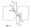
- FIG. 4is an end view of the blades of the bipolar electrosurgical scissors of FIG. 1 depicting the blades in an open condition with biological tissue positioned between the blades and the scissors energized in a second energized state with the tissue both between the blades and surrounding the blades being energized;
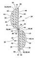
- FIG. 5is an end view, in cross-section, depicting the blades of the bipolar electrosurgical scissors with the blades in a laminated configuration
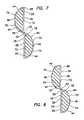
- FIG. 6is an end view, in cross-section, depicting the blades of the bipolar electrosurgical scissors with the electrodes being coupled onto an insulated body portion of the blades;
- FIG. 7is an end view, in cross-section, depicting the blades of the bipolar electrosurgical scissors with the electrodes being inlayed into an insulated body portion of the blades;
- FIG. 8is an end view, in cross-section, depicting the blades of the bipolar electrosurgical scissors with the electrodes being deposited onto an insulated body portion of the blades;
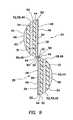
- FIG. 10is an end view, in cross-section, depicting the blades of the bipolar electrosurgical scissors with the electrodes being coupled onto an insulated body portion of the blades, similar to FIG. 6 but having additional electrodes on the shearing layer of the blades;
- FIG. 11is an end view, in cross-section, depicting the blades of the bipolar electrosurgical scissors with the electrodes being inlayed into an insulated body portion of the blades, similar to FIG. 7 but having additional electrodes on the shearing layer of the blades;
- FIG. 12is an end view, in cross-section, depicting the blades of the bipolar electrosurgical scissors with the electrodes being deposited onto an insulated body portion of the blades, similar to FIG. 8 but having additional electrodes on the shearing layer of the blades;
- FIG. 13is a side view depicting the electrosurgical scissors of FIG. 11 with the scissors energized in the second energized state to coagulate tissue with the side of the blade;
- FIG. 14is a side view depicting the electrosurgical scissors of FIG. 11 with the scissors energized in the second energized state to dissect tissue with the electrodes on the shearing layers of the blades;
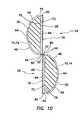
- FIG. 15is an end view of the blades of the bipolar electrosurgical scissors of FIG. 12 depicting the blades in an open condition with biological tissue positioned between the blades and the scissors energized in a first energized state with just the tissue between the blades being energized;
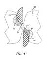
- FIG. 16is an end view of the blades of the bipolar electrosurgical scissors of FIG. 11 depicting the blades in an open condition with biological tissue positioned between the blades and the scissors energized in a second energized state with the tissue both between the blades and surrounding the blades being energized;
- FIG. 17is a side view depicting the electrosurgical scissors of FIG. 6 with the scissors energized in the second energized state to dissect tissue with the side of the blade.
- the inventionincludes bipolar electrosurgical scissors 20 for use in treating biological tissue 22 .
- the scissors 20include a first scissor blade 24 and a second scissor blade 26 .
- Each of the first and second blades 24 , 26includes a shearing surface 28 , an opposed surface 30 positioned opposite the shearing surface, a cutting edge 32 , a first, proximal end 31 , and a second, distal end 33 .
- a pivot pin 34pivotally couples the first blade 24 to the second blade 26 at a position proximal the shearing surfaces 28 of the first and second blades.
- the shearing surfaces 28 of the first and second blades 24 , 26face each other and interface with each other.
- the scissors 20may be part of a laparoscopic surgical instrument 36 .
- the scissors 20may be part of conventional electrosurgical shears 38 to be used in conventional, open surgery.
- the scissors 20include first and second electrical connections 40 , 42 .
- the first electrical connection 40receives an electrical current of a first polarity
- the second electrical connection 42receives an electrical current of a second polarity that is opposite to the electrical current of the first polarity.
- each of the first and second scissor blades 24 , 26includes at least one first electrode 44 and at least one second electrode 46 .
- Each of the first and second electrodes 44 , 46is positioned on the opposed surface 30 of the respective blade.
- the at least one first electrode 44 on the first bladeis coupled to the first electrical connection 40 ( FIG. 1 ).
- the at least one second electrode 46 on the first blade 26is coupled to the second electrical connection 42 ( FIG. 1 ).
- the at least one first electrode 44 on the second blade 26is coupled to the second electrical connection 42 .
- the at least one second electrode 46 on the second blade 26is coupled to the first electrical connection 40 .
- Each of the first and second electrodes 44 , 46includes a portion that is exposed on the opposed surface 30 of the respective blade 24 , 26 .
- the first and second electrodes 44 , 46extend lengthwise along the length of the opposed surfaces 30 of the first and second blades 24 , 26 .
- the shearing surface 28 of each of the blades 24 , 26is not coupled to either of the first and second electrical connections 40 , 42 .
- the shearing surface 28 of each of the first and second blades 24 , 26is electrically neutral.
- the first electrical connection 40delivers electrical current only to the at least one first electrode 44 on the first scissor blade 24 and the second electrical connection 42 delivers electrical current only to the at least one first electrode 44 on the second scissor blade 26 .
- the first electrical connection 40FIG. 1
- the second electrical connection 42FIG. 1
- the first and/or second scissor blade 24 , 26may include a laminated structure.
- FIG. 5depicts each of the first and second blades 24 , 26 including the laminated structure including at least a first, shearing layer 48 , a second layer 50 , a third layer 52 , a fourth layer 54 and a fifth layer 56 .
- the first layer 48coincides with the shearing surface 28 and cutting edge 32 of the scissor blades 24 , 26 .
- the first layer 48includes a first, shearing surface 49 and a second, opposed surface 51 , and is made of a material capable of forming a desirable cutting edge, such as a metal or other materials that are well known in the art.
- the shearing surface 28 of each of the first and second blades 24 , 26is electrically neutral.
- the first layer 48is not coupled to either of the first or second electrical connections 40 , 42 .
- the second layer 50is coupled to the second surface 51 of the first layer 48 .
- the third layer 52is coupled to the second layer 50 on the side opposite the first layer 48 .
- the third layer 52is electrically conductive.
- the fourth layer 54is coupled to the third layer 52 on the side opposite the second layer 50 .
- the fifth layer 56is coupled to the fourth layer 54 on the side opposite the third layer 52 .
- the fifth layer 56is electrically conductive.
- the third layer 52 of each of the scissor blades 24 , 26includes exposed portions 58 that form the at least one first electrode 44 of the first and second blades.
- the third layer 52 on the first blade 24is coupled to the first electrical connection 40 ( FIG. 1 ) and the third layer 52 on the second blade 26 is coupled to the second electrical connection 42 ( FIG. 1 ).
- the second layer 50completely separates the third, conductive layer 52 from the first, neutral layer 48 .
- the second layer 50is electrically nonconductive and is formed of a material that insulates against electrical current to prevent the current delivered to the third layer from flowing to the first layer.
- the fifth layer 56includes exposed portions 60 that form the at least one second electrode 46 on each of the first and second scissor blades 24 , 26 .
- the fifth layer 56 on the first blade 24is coupled to the second electrical connection 42 and the fifth layer 56 on the second blade 26 is coupled to the first electrical connection 40 .
- the fourth layer 54completely separates the fifth, conductive layer 56 from the third, conductive layer 52 , and the third layer has opposing polarity to the fifth layer.
- the fourth layer 54is electrically nonconductive and is formed of a material that insulates against electrical current to prevent shorting between the third and fifth 52 , 56 layers on the respective blades 24 , 26 .
- the electrically insulating material of the second and fourth layers 50 , 54 of the first and second scissor blades 24 , 26has sufficient dielectric strength to substantially prevent electrical breakdown of the insulating material.
- the exposed surfaces 58 of the third layer 52 of the first and second blades 24 , 26may form at least two first electrodes 44 on each of the first and second blades.
- the exposed surfaces 60 of the fifth layer 56 of the first and second blades 24 , 26may form at least one second electrode 46 on each of the first and second blades. As depicted in FIG.
- the exposed surfaces 60 of the fifth layer 56 of the first and second blades 24 , 26may form one second electrode 46 positioned between the at least two first electrodes 44 on each of the first and second blades.
- the shearing surfaces 28 and cutting edges 32 of the first and second blades 24 , 26may include a coating, such as a coating of amorphous diamond-like carbon or other suitable material that is well known in the art, to resist mechanical wear and friction between the blades.
- the first and/or second scissor blade 24 , 26may include an insulating body with a shearing layer and electrodes coupled to the insulating body.
- the first and second blades 24 , 26may include an insulating body with a shearing layer coupled to the insulating body and electrodes inlayed into the insulating body ( FIG. 7 ), electrodes deposited onto the insulating body ( FIG. 8 ), or include suitable electrodes in any other form that is well known in the art positioned on the insulating body.
- each of the first and second blades 24 , 26includes an insulating body 70 having a primary surface 72 corresponding with the shearing surface 28 , and a secondary surface 74 corresponding with the opposed surface 30 .
- a shearing layer 76is coupled to the primary surface 72 of the insulating body 70 .
- the shearing layer 76includes a first, shearing surface 28 , a second, opposed surface 78 , and the cutting edge 32 .
- the second, opposed surface 78 of the shearing layer 76is coupled to the primary surface 72 of the insulating body 70 .
- the shearing layer 76includes the shearing surface 28 and cutting edge 32 of the blades 24 , 26 , the shearing layer is made of a material capable of forming a desirable cutting edge, such as a metal or other material that is well known in the art.
- the shearing surface 28 of each of the first and second blades 24 , 26is electrically neutral.
- the shearing layer 76is not coupled to either of the first or second electrical connections 40 , 42 .
- the first scissor blade 24may include the at least one first electrode 44 and the at least one second electrode 46 coupled to ( FIG. 6 ), inlayed into ( FIG. 7 ), or deposited onto ( FIG. 8 ) the secondary surface 74 of the insulating body 70 of the first blade with the first and second electrodes positioned in an alternating relationship.
- the second scissor 26 blademay include the at least one first electrode 44 and the at least one second electrode 46 coupled to ( FIG. 6 ), inlayed into ( FIG. 7 ), or deposited onto ( FIG.
- the electrically insulating material of which the insulating body 70 of the first and second scissor blades 24 , 26 is formedhas sufficient dielectric strength to substantially prevent electrical breakdown of the electrically insulating material.
- the first and/or second scissor blade 24 , 26may include a laminated structure similar to the laminated structure of FIG. 5 with each of the first and second scissor blades 24 , 26 including at least the first layer 48 , the second layer 50 , the third layer 52 , the fourth layer 54 and the fifth layer 56 .
- FIG. 9depicts each of the first and second scissor blades 24 , 26 including the laminated structure.
- the first layer 48 of FIG. 9coincides with the shearing surface 28 and cutting edge 32 of the blades 24 , 26 .
- the first layer 48includes the first, shearing surface 49 and second, opposed surface 51 , and is made of a material capable of forming a desirable cutting edge, such as a metal or other materials that are well known in the art.
- the first layer 48also includes a first and second edge surface 80 , 82 with each edge surface including a first electrode 44 .
- the first electrodes 44 on the first and second edge surfaces 80 , 82 of the first blade 24are coupled to the first electrical connection 40 ( FIG. 1 ) and the first electrodes 44 on the first and second edge surfaces 80 , 82 of the second blade 26 are coupled to the second electrical connection 42 ( FIG. 1 ).
- the first edge surface 80 of the first layer 48 of each of the first and second blades 24 , 26coincides with the cutting edge 32 of the blades.
- the second layer 50 of each of the first and second scissor blades 24 , 26is coupled to the second surface 51 of the first layer 48 .
- the third layer 52is coupled to the second layer 50 on the side opposite the first layer 48 .
- the third layer 52is electrically conductive.
- the fourth layer 54is coupled to the third layer 52 on the side opposite the second layer 50 .
- the fifth layer 56is coupled to the fourth layer 54 on the side opposite the third layer 52 .
- the fifth layer 56is electrically conductive.
- the third layer 52 of each of the scissor blades 24 , 26includes exposed portions 58 that form the at least one second electrode 46 of the first and second blades.
- the third layer 52 on the first blade 24is coupled to the second electrical connection 42 ( FIG. 1 ) and the third layer 52 on the second blade 26 is coupled to the first electrical connection 40 ( FIG. 1 ).
- the second layer 50completely separates the third, conductive layer 52 from the first, conductive layer 48 .
- the fifth layer 56includes exposed portions 60 that form another first electrode 44 on each of the first and second scissor blades 24 , 26 .
- the fifth layer 56 on the first blade 24is coupled to the first electrical connection 40 ( FIG. 1 ) and the fifth layer 56 on the second blade 26 is coupled to the second electrical connection 42 ( FIG. 1 ).
- the fourth layer 54completely separates the fifth, conductive layer 56 from the third, conductive layer 52 .
- the third layer 52has opposing polarity to the first and fifth layers 48 , 56 .
- the second and fourth layers 50 , 54are electrically nonconductive and are formed of materials that insulate against electrical current to prevent electrical shorting between the third layer 52 and the first and fifth layers 48 , 56 on the respective blades.
- the electrically insulating material of the second and fourth layers 50 , 54 of the first and second scissor blades 24 , 26has sufficient dielectric strength to substantially prevent electrical breakdown of the insulating material.
- the exposed surfaces 58 of the third layer 52 of the first and second blades 24 , 26may form at least two second electrodes 46 on each of the first and second blades.
- the exposed surfaces 60 of the fifth layer 56 of the first and second scissor blades 24 , 26may form at least one first electrode 44 on each of the first and second scissor blades.
- the exposed surfaces 60 of the fifth layer 56 of the first and second scissor blades 24 , 26may form one first electrode 44 positioned between the at least two second electrodes 46 on each of the first and second blades.
- the shearing surfaces 28 and cutting edges 32 of each of the first and second blades 24 , 26may include an electrically insulating coating 84 , such as a coating of amorphous diamond-like carbon or other suitable electrically insulating material that is well known in the art.
- An amorphous diamond-like coatingfacilitates the prevention of electrical shorting through metallic blades 24 , 26 and resists mechanical wear and friction between the blades.
- portions of the first edge surface 80 and the second edge surface 82 proximate the shearing surface 28are also coated with the electrically insulating coating 84 to facilitate the prevention of electrical shorting through the blades.
- the portions of the first edge surface 80 and the second edge surface 82 that are proximate the second, opposed surface 51 of each of the first and second scissor blades 24 , 26are not covered with the electrically insulating coating 84 and, thereby, function as first electrodes 44 for each of the scissor blades.
- FIGS. 10-12are similar to FIGS. 6-8 , respectively.
- the first and/or second scissor blade 24 , 26may include an insulating body with a shearing layer coupled to the insulating body.
- the first and second blades 24 , 26may include electrodes coupled to the insulating body ( FIG. 10 ), electrodes inlayed into the insulating body ( FIG. 11 ), electrodes deposited onto the insulating body ( FIG. 12 ), or include suitable electrodes in any other form that is well known in the art positioned on the insulating body.
- each of the first and second scissor blades 24 , 26 of FIGS. 10-12includes the insulating body 70 having the primary surface 72 corresponding with the shearing surface 28 , and the secondary surface 74 corresponding with the opposed surface 30 .
- the shearing layer 76is coupled to the primary surface 72 of the insulating body 70 .
- the shearing layer 76includes the first, shearing surface 28 , the second, opposed surface 78 , and the cutting edge 32 .
- the shearing layer 76also includes the first and second edge surface 80 , 82 with each of the edge surfaces including a first electrode 44 .
- the first electrodes 44 on the first and second edge surfaces 80 , 82 of the first scissor blade 24are coupled to the first electrical connection 40 ( FIG. 1 ) and the first electrodes 44 on the first and second edge surfaces 80 , 82 of the second scissor blade 26 are coupled to the second electrical connection 42 ( FIG. 1 ).
- the first edge surface 80 of the shearing layer 76 of each of the first and second blades 24 , 26coincides with the cutting edge 32 of the blades.
- the second, opposed surface 78 of the shearing layer 76is coupled to the primary surface 72 of the insulating body 70 .
- the shearing layer 76includes the shearing surface 28 and cutting edge 32 of the blades 24 , 26 , the shearing layer is made of a material capable of forming a desirable cutting edge, such as a metallic material or other material that is well known in the art.
- the shearing surfaces 28 and cutting edges 32 of the shearing layers 76 of each of the first and second scissor blades 24 , 26may include an electrically insulating coating 84 , such as a coating of amorphous diamond-like carbon or other suitable electrically insulating material that is well known in the art.
- an electrically insulating coating 84such as a coating of amorphous diamond-like carbon or other suitable electrically insulating material that is well known in the art.
- portions of the first edge surface 80 and the second edge surface 82 proximate the shearing surface 28are also coated with the electrically insulating coating 84 .
- first edge surface 80 and the second edge surface 82 that are proximate the second, opposed surface 78 of each of the first and second blades 24 , 26are not covered with the electrically insulating coating 84 and, thereby, function as first electrodes 44 for each of the blades.
- the shearing layer 76 on each of the first and second blades 24 , 26may include a first electrode 44 on only one of the first and second edge surfaces 80 , 82 .
- the first scissor blade 24may include at least one first electrode 44 and at least one second electrode 46 coupled to ( FIG. 10 ), inlayed into ( FIG. 11 ), or deposited onto ( FIG. 12 ) the secondary surface 74 of the insulating body 70 of the first blade with the first and second electrodes positioned in an alternating relationship.
- the second scissor 26 blademay include at least one first electrode 44 and at least one second electrode 46 coupled to ( FIG. 10 ), inlayed into ( FIG. 11 ), or deposited onto ( FIG.
- the electrically insulating material of which the insulating body 70 of the first and second scissor blades 24 , 26 is formedhas sufficient dielectric strength to substantially prevent electrical breakdown of the electrically insulating material.
- the distance between the at least one first electrode 44 and the at least one second electrode 46is sufficient to prevent electrical arcing between the electrodes.
- the distance between the at least one first electrode 44 and the at least one second electrode 46is small enough to permit simultaneous connection between the tissue 22 and two respective electrodes 44 , 46 having opposing polarity (see FIG. 13 ).
- the distance between the first electrodes 44 on the first scissor blade 24 at the first and second edge surfaces 80 , 82 and the first electrodes 44 on the second scissor blade 26 at the first and second edges 80 , 82is sufficient to prevent electrical arcing between the first electrodes on the first blade and the first electrodes on the second blade.
- the distance between the first electrodes 44 on the first blade 24 and the first electrodes 44 on the second blade 26is small enough to permit simultaneous connection between the tissue 22 and the first electrodes, which have opposing polarity, on adjacent edge surfaces 80 , 82 of the shearing layers 76 of the first and second blades.
- the bipolar electrosurgical scissors 20 of the present inventionmay be used for numerous surgical functions, including functions that have typically been reserved for monopolar surgical devices.
- the scissors 20in the first energized state, as discussed above, the scissors 20 may be used to coagulate tissue 22 between the first and second scissor blades 24 , 26 prior to mechanically cutting the tissue (see FIGS. 2 and 15 ).
- the scissors 20are positioned in an open condition with the tissue 22 between the open blades 24 , 26 .
- the first electrical connection 40FIG. 1
- the second electrical connection 42FIG. 1
- the currenttravels mainly between the activated electrodes 44 , thereby coagulating the tissue 22 between the open blades 24 , 26 prior to the tissue being cut.
- the tissue 22 surrounding the tissue being mechanically cutis coagulated.
- the tissue 22 being cutmay also be coagulated in addition to coagulation of the tissue that is surrounding the tissue being cut.
- the opposed surface 30 of one of the first and second scissor blades 24 , 26may be applied to tissue 22 to coagulate the tissue, similar to as is done with monopolar surgical devices.
- first and second electrodes 44 , 46are positioned such that each of a first and second electrode on one of the first and second scissor blades 24 , 26 may be in contact with the tissue 22 at the same time.
- adjacent first electrodes on the edge surfaces 80 , 82 of the shearing layers 76 of the first and second scissor blades 24 , 26may be moved across the tissue 22 in a sweeping motion to electrically dissect the tissue, similar to as is done with monopolar surgical devices.
- the opposed surface 30 of one of the first and second scissor blades 24 , 26may be moved across the tissue 22 in a sweeping motion to electrically dissect the tissue.
Landscapes
- Health & Medical Sciences (AREA)
- Surgery (AREA)
- Engineering & Computer Science (AREA)
- Life Sciences & Earth Sciences (AREA)
- Biomedical Technology (AREA)
- Otolaryngology (AREA)
- Nuclear Medicine, Radiotherapy & Molecular Imaging (AREA)
- Plasma & Fusion (AREA)
- Physics & Mathematics (AREA)
- Heart & Thoracic Surgery (AREA)
- Medical Informatics (AREA)
- Molecular Biology (AREA)
- Animal Behavior & Ethology (AREA)
- General Health & Medical Sciences (AREA)
- Public Health (AREA)
- Veterinary Medicine (AREA)
- Surgical Instruments (AREA)
Abstract
Description
Claims (13)
Priority Applications (1)
| Application Number | Priority Date | Filing Date | Title |
|---|---|---|---|
| US13/555,609US8597293B2 (en) | 2006-07-27 | 2012-07-23 | Bipolar electrosurgical scissors |
Applications Claiming Priority (3)
| Application Number | Priority Date | Filing Date | Title |
|---|---|---|---|
| US11/460,292US7419490B2 (en) | 2006-07-27 | 2006-07-27 | Bipolar electrosurgical scissors |
| US12/183,970US8226649B2 (en) | 2006-07-27 | 2008-07-31 | Bipolar electrosurgical scissors |
| US13/555,609US8597293B2 (en) | 2006-07-27 | 2012-07-23 | Bipolar electrosurgical scissors |
Related Parent Applications (1)
| Application Number | Title | Priority Date | Filing Date |
|---|---|---|---|
| US12/183,970ContinuationUS8226649B2 (en) | 2006-07-27 | 2008-07-31 | Bipolar electrosurgical scissors |
Publications (2)
| Publication Number | Publication Date |
|---|---|
| US20120289958A1 US20120289958A1 (en) | 2012-11-15 |
| US8597293B2true US8597293B2 (en) | 2013-12-03 |
Family
ID=38982192
Family Applications (3)
| Application Number | Title | Priority Date | Filing Date |
|---|---|---|---|
| US11/460,292Active2027-03-01US7419490B2 (en) | 2006-07-27 | 2006-07-27 | Bipolar electrosurgical scissors |
| US12/183,970Active2029-05-20US8226649B2 (en) | 2006-07-27 | 2008-07-31 | Bipolar electrosurgical scissors |
| US13/555,609ActiveUS8597293B2 (en) | 2006-07-27 | 2012-07-23 | Bipolar electrosurgical scissors |
Family Applications Before (2)
| Application Number | Title | Priority Date | Filing Date |
|---|---|---|---|
| US11/460,292Active2027-03-01US7419490B2 (en) | 2006-07-27 | 2006-07-27 | Bipolar electrosurgical scissors |
| US12/183,970Active2029-05-20US8226649B2 (en) | 2006-07-27 | 2008-07-31 | Bipolar electrosurgical scissors |
Country Status (3)
| Country | Link |
|---|---|
| US (3) | US7419490B2 (en) |
| EP (1) | EP2046221B1 (en) |
| WO (1) | WO2008014103A2 (en) |
Cited By (10)
| Publication number | Priority date | Publication date | Assignee | Title |
|---|---|---|---|---|
| US9050101B1 (en) | 2013-11-19 | 2015-06-09 | Ryan D. Smith | Surgical multi-tool and method of use |
| US9943327B2 (en) | 2016-06-21 | 2018-04-17 | Divyze, Inc. | Surgical multi-tool and method of use |
| US11365490B2 (en) | 2019-12-21 | 2022-06-21 | Covidien Lp | Thermal cutting elements, electrosurgical instruments including thermal cutting elements, and methods of manufacturing |
| US11529186B2 (en) | 2019-07-22 | 2022-12-20 | Covidien Lp | Electrosurgical forceps including thermal cutting element |
| US12023087B2 (en) | 2017-03-15 | 2024-07-02 | Cilag Gmbh International | Electrosurgical instrument with textured jaws |
| US12048472B2 (en) | 2021-02-01 | 2024-07-30 | Covidien Lp | Electrosurgical instruments, jaw members thereof, and methods of manufacturing |
| US12167885B2 (en) | 2019-08-16 | 2024-12-17 | Divyze, Inc. | Electrosurgical energy adapter, electrosurgical energy control, and surgical multi-tool |
| US12251155B2 (en) | 2021-05-27 | 2025-03-18 | Covidien Lp | Methods for open dissection using sealing instrument |
| US12295644B2 (en) | 2016-09-23 | 2025-05-13 | Cilag Gmbh International | Electrosurgical instrument with fluid diverter |
| US12408970B2 (en) | 2020-04-02 | 2025-09-09 | Covidien Lp | Systems and methods for sealing and dissecting tissue using an electrosurgical forceps including a thermal cutting element |
Families Citing this family (167)
| Publication number | Priority date | Publication date | Assignee | Title |
|---|---|---|---|---|
| US11229472B2 (en) | 2001-06-12 | 2022-01-25 | Cilag Gmbh International | Modular battery powered handheld surgical instrument with multiple magnetic position sensors |
| US20080121343A1 (en) | 2003-12-31 | 2008-05-29 | Microfabrica Inc. | Electrochemical Fabrication Methods Incorporating Dielectric Materials and/or Using Dielectric Substrates |
| US8182501B2 (en) | 2004-02-27 | 2012-05-22 | Ethicon Endo-Surgery, Inc. | Ultrasonic surgical shears and method for sealing a blood vessel using same |
| US20060079879A1 (en) | 2004-10-08 | 2006-04-13 | Faller Craig N | Actuation mechanism for use with an ultrasonic surgical instrument |
| US20070191713A1 (en) | 2005-10-14 | 2007-08-16 | Eichmann Stephen E | Ultrasonic device for cutting and coagulating |
| US7621930B2 (en) | 2006-01-20 | 2009-11-24 | Ethicon Endo-Surgery, Inc. | Ultrasound medical instrument having a medical ultrasonic blade |
| US7419490B2 (en)* | 2006-07-27 | 2008-09-02 | Applied Medical Resources Corporation | Bipolar electrosurgical scissors |
| US8142461B2 (en) | 2007-03-22 | 2012-03-27 | Ethicon Endo-Surgery, Inc. | Surgical instruments |
| US8226675B2 (en) | 2007-03-22 | 2012-07-24 | Ethicon Endo-Surgery, Inc. | Surgical instruments |
| US8911460B2 (en) | 2007-03-22 | 2014-12-16 | Ethicon Endo-Surgery, Inc. | Ultrasonic surgical instruments |
| US8057498B2 (en) | 2007-11-30 | 2011-11-15 | Ethicon Endo-Surgery, Inc. | Ultrasonic surgical instrument blades |
| US8523889B2 (en) | 2007-07-27 | 2013-09-03 | Ethicon Endo-Surgery, Inc. | Ultrasonic end effectors with increased active length |
| US8808319B2 (en) | 2007-07-27 | 2014-08-19 | Ethicon Endo-Surgery, Inc. | Surgical instruments |
| US8882791B2 (en) | 2007-07-27 | 2014-11-11 | Ethicon Endo-Surgery, Inc. | Ultrasonic surgical instruments |
| US8512365B2 (en) | 2007-07-31 | 2013-08-20 | Ethicon Endo-Surgery, Inc. | Surgical instruments |
| US8430898B2 (en) | 2007-07-31 | 2013-04-30 | Ethicon Endo-Surgery, Inc. | Ultrasonic surgical instruments |
| US9044261B2 (en) | 2007-07-31 | 2015-06-02 | Ethicon Endo-Surgery, Inc. | Temperature controlled ultrasonic surgical instruments |
| EP2217157A2 (en) | 2007-10-05 | 2010-08-18 | Ethicon Endo-Surgery, Inc. | Ergonomic surgical instruments |
| US10010339B2 (en) | 2007-11-30 | 2018-07-03 | Ethicon Llc | Ultrasonic surgical blades |
| CN103398494B (en) | 2008-03-05 | 2017-03-01 | 史泰克公司 | Cooling system and the method for operation thermoelectric cooling system |
| US10939934B2 (en) | 2008-06-23 | 2021-03-09 | Microfabrica Inc. | Miniature shredding tools for use in medical applications, methods for making, and procedures for using |
| US8968346B2 (en) | 2008-06-23 | 2015-03-03 | Microfabrica Inc. | Miniature shredding tool for use in medical applications and methods for making |
| US9814484B2 (en) | 2012-11-29 | 2017-11-14 | Microfabrica Inc. | Micro debrider devices and methods of tissue removal |
| US20170095264A1 (en)* | 2008-06-23 | 2017-04-06 | Gregory P. Schmitz | Surgical micro-shears and methods of fabrication and use |
| US9089360B2 (en) | 2008-08-06 | 2015-07-28 | Ethicon Endo-Surgery, Inc. | Devices and techniques for cutting and coagulating tissue |
| GB2462453B (en) | 2008-08-06 | 2012-05-09 | Gyrus Medical Ltd | Electrosurgical instrument and system |
| US9700339B2 (en) | 2009-05-20 | 2017-07-11 | Ethicon Endo-Surgery, Inc. | Coupling arrangements and methods for attaching tools to ultrasonic surgical instruments |
| US8650728B2 (en) | 2009-06-24 | 2014-02-18 | Ethicon Endo-Surgery, Inc. | Method of assembling a transducer for a surgical instrument |
| US8663220B2 (en) | 2009-07-15 | 2014-03-04 | Ethicon Endo-Surgery, Inc. | Ultrasonic surgical instruments |
| EP3175803A1 (en) | 2009-08-18 | 2017-06-07 | Microfabrica Inc. | Concentric cutting devices for use in minimally invasive medical procedures |
| US11090104B2 (en) | 2009-10-09 | 2021-08-17 | Cilag Gmbh International | Surgical generator for ultrasonic and electrosurgical devices |
| USRE47996E1 (en) | 2009-10-09 | 2020-05-19 | Ethicon Llc | Surgical generator for ultrasonic and electrosurgical devices |
| US10441345B2 (en) | 2009-10-09 | 2019-10-15 | Ethicon Llc | Surgical generator for ultrasonic and electrosurgical devices |
| US9168054B2 (en) | 2009-10-09 | 2015-10-27 | Ethicon Endo-Surgery, Inc. | Surgical generator for ultrasonic and electrosurgical devices |
| US9050093B2 (en) | 2009-10-09 | 2015-06-09 | Ethicon Endo-Surgery, Inc. | Surgical generator for ultrasonic and electrosurgical devices |
| US8579928B2 (en) | 2010-02-11 | 2013-11-12 | Ethicon Endo-Surgery, Inc. | Outer sheath and blade arrangements for ultrasonic surgical instruments |
| US8951272B2 (en) | 2010-02-11 | 2015-02-10 | Ethicon Endo-Surgery, Inc. | Seal arrangements for ultrasonically powered surgical instruments |
| US8961547B2 (en) | 2010-02-11 | 2015-02-24 | Ethicon Endo-Surgery, Inc. | Ultrasonic surgical instruments with moving cutting implement |
| US8486096B2 (en) | 2010-02-11 | 2013-07-16 | Ethicon Endo-Surgery, Inc. | Dual purpose surgical instrument for cutting and coagulating tissue |
| US8469981B2 (en) | 2010-02-11 | 2013-06-25 | Ethicon Endo-Surgery, Inc. | Rotatable cutting implement arrangements for ultrasonic surgical instruments |
| GB2480498A (en) | 2010-05-21 | 2011-11-23 | Ethicon Endo Surgery Inc | Medical device comprising RF circuitry |
| US8795327B2 (en) | 2010-07-22 | 2014-08-05 | Ethicon Endo-Surgery, Inc. | Electrosurgical instrument with separate closure and cutting members |
| US9192431B2 (en) | 2010-07-23 | 2015-11-24 | Ethicon Endo-Surgery, Inc. | Electrosurgical cutting and sealing instrument |
| US8888809B2 (en)* | 2010-10-01 | 2014-11-18 | Ethicon Endo-Surgery, Inc. | Surgical instrument with jaw member |
| US8979890B2 (en) | 2010-10-01 | 2015-03-17 | Ethicon Endo-Surgery, Inc. | Surgical instrument with jaw member |
| US9259265B2 (en) | 2011-07-22 | 2016-02-16 | Ethicon Endo-Surgery, Llc | Surgical instruments for tensioning tissue |
| WO2013119545A1 (en) | 2012-02-10 | 2013-08-15 | Ethicon-Endo Surgery, Inc. | Robotically controlled surgical instrument |
| US9237921B2 (en) | 2012-04-09 | 2016-01-19 | Ethicon Endo-Surgery, Inc. | Devices and techniques for cutting and coagulating tissue |
| US9241731B2 (en) | 2012-04-09 | 2016-01-26 | Ethicon Endo-Surgery, Inc. | Rotatable electrical connection for ultrasonic surgical instruments |
| US9724118B2 (en) | 2012-04-09 | 2017-08-08 | Ethicon Endo-Surgery, Llc | Techniques for cutting and coagulating tissue for ultrasonic surgical instruments |
| US9439668B2 (en) | 2012-04-09 | 2016-09-13 | Ethicon Endo-Surgery, Llc | Switch arrangements for ultrasonic surgical instruments |
| US9226766B2 (en) | 2012-04-09 | 2016-01-05 | Ethicon Endo-Surgery, Inc. | Serial communication protocol for medical device |
| TWI627130B (en)* | 2012-04-18 | 2018-06-21 | 美商艾克頌美孚上游研究公司 | Removing carbon nanotubes from a continuous reactor effluent |
| US9084606B2 (en) | 2012-06-01 | 2015-07-21 | Megadyne Medical Products, Inc. | Electrosurgical scissors |
| US20140005705A1 (en) | 2012-06-29 | 2014-01-02 | Ethicon Endo-Surgery, Inc. | Surgical instruments with articulating shafts |
| US9226767B2 (en) | 2012-06-29 | 2016-01-05 | Ethicon Endo-Surgery, Inc. | Closed feedback control for electrosurgical device |
| US9198714B2 (en) | 2012-06-29 | 2015-12-01 | Ethicon Endo-Surgery, Inc. | Haptic feedback devices for surgical robot |
| US9326788B2 (en) | 2012-06-29 | 2016-05-03 | Ethicon Endo-Surgery, Llc | Lockout mechanism for use with robotic electrosurgical device |
| US9820768B2 (en) | 2012-06-29 | 2017-11-21 | Ethicon Llc | Ultrasonic surgical instruments with control mechanisms |
| US9283045B2 (en) | 2012-06-29 | 2016-03-15 | Ethicon Endo-Surgery, Llc | Surgical instruments with fluid management system |
| US9393037B2 (en) | 2012-06-29 | 2016-07-19 | Ethicon Endo-Surgery, Llc | Surgical instruments with articulating shafts |
| US9351754B2 (en) | 2012-06-29 | 2016-05-31 | Ethicon Endo-Surgery, Llc | Ultrasonic surgical instruments with distally positioned jaw assemblies |
| US9408622B2 (en) | 2012-06-29 | 2016-08-09 | Ethicon Endo-Surgery, Llc | Surgical instruments with articulating shafts |
| US20140005702A1 (en) | 2012-06-29 | 2014-01-02 | Ethicon Endo-Surgery, Inc. | Ultrasonic surgical instruments with distally positioned transducers |
| EP2900158B1 (en) | 2012-09-28 | 2020-04-15 | Ethicon LLC | Multi-function bi-polar forceps |
| US10201365B2 (en) | 2012-10-22 | 2019-02-12 | Ethicon Llc | Surgeon feedback sensing and display methods |
| US9095367B2 (en) | 2012-10-22 | 2015-08-04 | Ethicon Endo-Surgery, Inc. | Flexible harmonic waveguides/blades for surgical instruments |
| US20140135804A1 (en) | 2012-11-15 | 2014-05-15 | Ethicon Endo-Surgery, Inc. | Ultrasonic and electrosurgical devices |
| WO2014100808A1 (en)* | 2012-12-23 | 2014-06-26 | Sheetak Inc. | Thermoelectric devices with blocked phonon conduction |
| US20140221994A1 (en)* | 2013-02-05 | 2014-08-07 | Covidien Lp | Electrosurgical instrument |
| US10226273B2 (en) | 2013-03-14 | 2019-03-12 | Ethicon Llc | Mechanical fasteners for use with surgical energy devices |
| US9241728B2 (en) | 2013-03-15 | 2016-01-26 | Ethicon Endo-Surgery, Inc. | Surgical instrument with multiple clamping mechanisms |
| CN105380711B (en) | 2013-03-15 | 2018-01-02 | 捷锐士阿希迈公司(以奥林巴斯美国外科技术名义) | Combine electrosurgery device |
| JP6141506B2 (en) | 2013-03-15 | 2017-06-07 | ジャイラス エーシーエムアイ インク | Combined electrosurgical device |
| CN105142556B (en) | 2013-03-15 | 2019-01-08 | 捷锐士阿希迈公司(以奥林巴斯美国外科技术名义) | Bias surgical clamp |
| JP6153654B2 (en) | 2013-03-15 | 2017-06-28 | ジャイラス エーシーエムアイ インク | Combined electrosurgical device |
| WO2014143472A1 (en) | 2013-03-15 | 2014-09-18 | GYRUS ACMI, INC. (d/b/a OLYMPUS SURGICAL TECHNOLOGIES AMERICA) | Electrosurgical instrument |
| US9814514B2 (en) | 2013-09-13 | 2017-11-14 | Ethicon Llc | Electrosurgical (RF) medical instruments for cutting and coagulating tissue |
| US9717548B2 (en) | 2013-09-24 | 2017-08-01 | Covidien Lp | Electrode for use in a bipolar electrosurgical instrument |
| US9265926B2 (en) | 2013-11-08 | 2016-02-23 | Ethicon Endo-Surgery, Llc | Electrosurgical devices |
| GB2521229A (en) | 2013-12-16 | 2015-06-17 | Ethicon Endo Surgery Inc | Medical device |
| GB2521228A (en) | 2013-12-16 | 2015-06-17 | Ethicon Endo Surgery Inc | Medical device |
| US9795436B2 (en) | 2014-01-07 | 2017-10-24 | Ethicon Llc | Harvesting energy from a surgical generator |
| US9554854B2 (en) | 2014-03-18 | 2017-01-31 | Ethicon Endo-Surgery, Llc | Detecting short circuits in electrosurgical medical devices |
| US10463421B2 (en) | 2014-03-27 | 2019-11-05 | Ethicon Llc | Two stage trigger, clamp and cut bipolar vessel sealer |
| US10092310B2 (en) | 2014-03-27 | 2018-10-09 | Ethicon Llc | Electrosurgical devices |
| US9737355B2 (en) | 2014-03-31 | 2017-08-22 | Ethicon Llc | Controlling impedance rise in electrosurgical medical devices |
| US10278768B2 (en) | 2014-04-02 | 2019-05-07 | Covidien Lp | Electrosurgical devices including transverse electrode configurations |
| US10123835B2 (en) | 2014-04-02 | 2018-11-13 | Covidien Lp | Electrosurgical devices including transverse electrode configurations and methods relating to the same |
| US9913680B2 (en) | 2014-04-15 | 2018-03-13 | Ethicon Llc | Software algorithms for electrosurgical instruments |
| US10258404B2 (en) | 2014-04-24 | 2019-04-16 | Gyrus, ACMI, Inc. | Partially covered jaw electrodes |
| US9700333B2 (en) | 2014-06-30 | 2017-07-11 | Ethicon Llc | Surgical instrument with variable tissue compression |
| US10285724B2 (en) | 2014-07-31 | 2019-05-14 | Ethicon Llc | Actuation mechanisms and load adjustment assemblies for surgical instruments |
| WO2016028835A1 (en) | 2014-08-20 | 2016-02-25 | GYRUS ACMI, INC. (d/b/a OLYMPUS SURGICAL TECHNOLOGIES AMERICA) | Surgical forceps and latching system |
| US10639092B2 (en) | 2014-12-08 | 2020-05-05 | Ethicon Llc | Electrode configurations for surgical instruments |
| USD748259S1 (en) | 2014-12-29 | 2016-01-26 | Applied Medical Resources Corporation | Electrosurgical instrument |
| US10245095B2 (en) | 2015-02-06 | 2019-04-02 | Ethicon Llc | Electrosurgical instrument with rotation and articulation mechanisms |
| US10342602B2 (en) | 2015-03-17 | 2019-07-09 | Ethicon Llc | Managing tissue treatment |
| US10321950B2 (en) | 2015-03-17 | 2019-06-18 | Ethicon Llc | Managing tissue treatment |
| EP3581133A1 (en) | 2015-03-23 | 2019-12-18 | Gyrus ACMI, Inc. (D.B.A. Olympus Surgical Technologies America) | Medical forceps with vessel transection capability |
| US10595929B2 (en) | 2015-03-24 | 2020-03-24 | Ethicon Llc | Surgical instruments with firing system overload protection mechanisms |
| US10034684B2 (en) | 2015-06-15 | 2018-07-31 | Ethicon Llc | Apparatus and method for dissecting and coagulating tissue |
| US11020140B2 (en) | 2015-06-17 | 2021-06-01 | Cilag Gmbh International | Ultrasonic surgical blade for use with ultrasonic surgical instruments |
| US11051873B2 (en) | 2015-06-30 | 2021-07-06 | Cilag Gmbh International | Surgical system with user adaptable techniques employing multiple energy modalities based on tissue parameters |
| US10034704B2 (en) | 2015-06-30 | 2018-07-31 | Ethicon Llc | Surgical instrument with user adaptable algorithms |
| US10357303B2 (en) | 2015-06-30 | 2019-07-23 | Ethicon Llc | Translatable outer tube for sealing using shielded lap chole dissector |
| US11141213B2 (en) | 2015-06-30 | 2021-10-12 | Cilag Gmbh International | Surgical instrument with user adaptable techniques |
| US11129669B2 (en) | 2015-06-30 | 2021-09-28 | Cilag Gmbh International | Surgical system with user adaptable techniques based on tissue type |
| US10898256B2 (en) | 2015-06-30 | 2021-01-26 | Ethicon Llc | Surgical system with user adaptable techniques based on tissue impedance |
| US10154852B2 (en) | 2015-07-01 | 2018-12-18 | Ethicon Llc | Ultrasonic surgical blade with improved cutting and coagulation features |
| US10194973B2 (en) | 2015-09-30 | 2019-02-05 | Ethicon Llc | Generator for digitally generating electrical signal waveforms for electrosurgical and ultrasonic surgical instruments |
| US10595930B2 (en) | 2015-10-16 | 2020-03-24 | Ethicon Llc | Electrode wiping surgical device |
| US10179022B2 (en) | 2015-12-30 | 2019-01-15 | Ethicon Llc | Jaw position impedance limiter for electrosurgical instrument |
| US10575892B2 (en) | 2015-12-31 | 2020-03-03 | Ethicon Llc | Adapter for electrical surgical instruments |
| US12193698B2 (en) | 2016-01-15 | 2025-01-14 | Cilag Gmbh International | Method for self-diagnosing operation of a control switch in a surgical instrument system |
| US10716615B2 (en) | 2016-01-15 | 2020-07-21 | Ethicon Llc | Modular battery powered handheld surgical instrument with curved end effectors having asymmetric engagement between jaw and blade |
| US11129670B2 (en) | 2016-01-15 | 2021-09-28 | Cilag Gmbh International | Modular battery powered handheld surgical instrument with selective application of energy based on button displacement, intensity, or local tissue characterization |
| US11229471B2 (en) | 2016-01-15 | 2022-01-25 | Cilag Gmbh International | Modular battery powered handheld surgical instrument with selective application of energy based on tissue characterization |
| US11051840B2 (en) | 2016-01-15 | 2021-07-06 | Ethicon Llc | Modular battery powered handheld surgical instrument with reusable asymmetric handle housing |
| US10555769B2 (en) | 2016-02-22 | 2020-02-11 | Ethicon Llc | Flexible circuits for electrosurgical instrument |
| US10702329B2 (en) | 2016-04-29 | 2020-07-07 | Ethicon Llc | Jaw structure with distal post for electrosurgical instruments |
| US10646269B2 (en) | 2016-04-29 | 2020-05-12 | Ethicon Llc | Non-linear jaw gap for electrosurgical instruments |
| US10485607B2 (en) | 2016-04-29 | 2019-11-26 | Ethicon Llc | Jaw structure with distal closure for electrosurgical instruments |
| US10456193B2 (en) | 2016-05-03 | 2019-10-29 | Ethicon Llc | Medical device with a bilateral jaw configuration for nerve stimulation |
| US10245064B2 (en) | 2016-07-12 | 2019-04-02 | Ethicon Llc | Ultrasonic surgical instrument with piezoelectric central lumen transducer |
| US10893883B2 (en) | 2016-07-13 | 2021-01-19 | Ethicon Llc | Ultrasonic assembly for use with ultrasonic surgical instruments |
| US10842522B2 (en) | 2016-07-15 | 2020-11-24 | Ethicon Llc | Ultrasonic surgical instruments having offset blades |
| US10376305B2 (en) | 2016-08-05 | 2019-08-13 | Ethicon Llc | Methods and systems for advanced harmonic energy |
| US10285723B2 (en) | 2016-08-09 | 2019-05-14 | Ethicon Llc | Ultrasonic surgical blade with improved heel portion |
| USD847990S1 (en) | 2016-08-16 | 2019-05-07 | Ethicon Llc | Surgical instrument |
| US10952759B2 (en) | 2016-08-25 | 2021-03-23 | Ethicon Llc | Tissue loading of a surgical instrument |
| US10736649B2 (en) | 2016-08-25 | 2020-08-11 | Ethicon Llc | Electrical and thermal connections for ultrasonic transducer |
| US10603064B2 (en) | 2016-11-28 | 2020-03-31 | Ethicon Llc | Ultrasonic transducer |
| US11266430B2 (en) | 2016-11-29 | 2022-03-08 | Cilag Gmbh International | End effector control and calibration |
| US10820920B2 (en) | 2017-07-05 | 2020-11-03 | Ethicon Llc | Reusable ultrasonic medical devices and methods of their use |
| US10667834B2 (en) | 2017-11-02 | 2020-06-02 | Gyrus Acmi, Inc. | Bias device for biasing a gripping device with a shuttle on a central body |
| US11383373B2 (en) | 2017-11-02 | 2022-07-12 | Gyms Acmi, Inc. | Bias device for biasing a gripping device by biasing working arms apart |
| US11298801B2 (en) | 2017-11-02 | 2022-04-12 | Gyrus Acmi, Inc. | Bias device for biasing a gripping device including a central body and shuttles on the working arms |
| US12053224B2 (en) | 2019-12-30 | 2024-08-06 | Cilag Gmbh International | Variation in electrode parameters and deflectable electrode to modify energy density and tissue interaction |
| US12023086B2 (en) | 2019-12-30 | 2024-07-02 | Cilag Gmbh International | Electrosurgical instrument for delivering blended energy modalities to tissue |
| US11786294B2 (en) | 2019-12-30 | 2023-10-17 | Cilag Gmbh International | Control program for modular combination energy device |
| US11786291B2 (en) | 2019-12-30 | 2023-10-17 | Cilag Gmbh International | Deflectable support of RF energy electrode with respect to opposing ultrasonic blade |
| US11684412B2 (en) | 2019-12-30 | 2023-06-27 | Cilag Gmbh International | Surgical instrument with rotatable and articulatable surgical end effector |
| US20210196357A1 (en) | 2019-12-30 | 2021-07-01 | Ethicon Llc | Electrosurgical instrument with asynchronous energizing electrodes |
| US11779387B2 (en) | 2019-12-30 | 2023-10-10 | Cilag Gmbh International | Clamp arm jaw to minimize tissue sticking and improve tissue control |
| US12262937B2 (en) | 2019-12-30 | 2025-04-01 | Cilag Gmbh International | User interface for surgical instrument with combination energy modality end-effector |
| US12336747B2 (en) | 2019-12-30 | 2025-06-24 | Cilag Gmbh International | Method of operating a combination ultrasonic / bipolar RF surgical device with a combination energy modality end-effector |
| US12114912B2 (en) | 2019-12-30 | 2024-10-15 | Cilag Gmbh International | Non-biased deflectable electrode to minimize contact between ultrasonic blade and electrode |
| US11812957B2 (en) | 2019-12-30 | 2023-11-14 | Cilag Gmbh International | Surgical instrument comprising a signal interference resolution system |
| US11452525B2 (en) | 2019-12-30 | 2022-09-27 | Cilag Gmbh International | Surgical instrument comprising an adjustment system |
| US12343063B2 (en) | 2019-12-30 | 2025-07-01 | Cilag Gmbh International | Multi-layer clamp arm pad for enhanced versatility and performance of a surgical device |
| US11944366B2 (en) | 2019-12-30 | 2024-04-02 | Cilag Gmbh International | Asymmetric segmented ultrasonic support pad for cooperative engagement with a movable RF electrode |
| US11950797B2 (en) | 2019-12-30 | 2024-04-09 | Cilag Gmbh International | Deflectable electrode with higher distal bias relative to proximal bias |
| US12082808B2 (en) | 2019-12-30 | 2024-09-10 | Cilag Gmbh International | Surgical instrument comprising a control system responsive to software configurations |
| US11696776B2 (en) | 2019-12-30 | 2023-07-11 | Cilag Gmbh International | Articulatable surgical instrument |
| US11937866B2 (en) | 2019-12-30 | 2024-03-26 | Cilag Gmbh International | Method for an electrosurgical procedure |
| US12064109B2 (en) | 2019-12-30 | 2024-08-20 | Cilag Gmbh International | Surgical instrument comprising a feedback control circuit |
| US20210196362A1 (en) | 2019-12-30 | 2021-07-01 | Ethicon Llc | Electrosurgical end effectors with thermally insulative and thermally conductive portions |
| US11660089B2 (en) | 2019-12-30 | 2023-05-30 | Cilag Gmbh International | Surgical instrument comprising a sensing system |
| US11779329B2 (en) | 2019-12-30 | 2023-10-10 | Cilag Gmbh International | Surgical instrument comprising a flex circuit including a sensor system |
| US11937863B2 (en) | 2019-12-30 | 2024-03-26 | Cilag Gmbh International | Deflectable electrode with variable compression bias along the length of the deflectable electrode |
| US11911063B2 (en) | 2019-12-30 | 2024-02-27 | Cilag Gmbh International | Techniques for detecting ultrasonic blade to electrode contact and reducing power to ultrasonic blade |
| US11986201B2 (en) | 2019-12-30 | 2024-05-21 | Cilag Gmbh International | Method for operating a surgical instrument |
| US12076006B2 (en) | 2019-12-30 | 2024-09-03 | Cilag Gmbh International | Surgical instrument comprising an orientation detection system |
| US12053229B2 (en) | 2020-06-30 | 2024-08-06 | Covidien Lp | Vessel sealing instrument with seal plates for directing the flow of energy |
| US12127781B2 (en) | 2020-06-30 | 2024-10-29 | Covidien Lp | Vessel sealing instrument with seal plates for directing the flow of energy |
| GB2600959A (en)* | 2020-11-12 | 2022-05-18 | Creo Medical Ltd | Electrosurgical resector tool |
Citations (43)
| Publication number | Priority date | Publication date | Assignee | Title |
|---|---|---|---|---|
| US3460539A (en) | 1967-03-10 | 1969-08-12 | James E Anhalt Sr | Cautery tip |
| US3987795A (en) | 1974-08-28 | 1976-10-26 | Valleylab, Inc. | Electrosurgical devices having sesquipolar electrode structures incorporated therein |
| US4202337A (en) | 1977-06-14 | 1980-05-13 | Concept, Inc. | Bipolar electrosurgical knife |
| US4228800A (en) | 1978-04-04 | 1980-10-21 | Concept, Inc. | Bipolar electrosurgical knife |
| US4850353A (en) | 1988-08-08 | 1989-07-25 | Everest Medical Corporation | Silicon nitride electrosurgical blade |
| US5324289A (en)* | 1991-06-07 | 1994-06-28 | Hemostatic Surgery Corporation | Hemostatic bi-polar electrosurgical cutting apparatus and methods of use |
| US5443463A (en) | 1992-05-01 | 1995-08-22 | Vesta Medical, Inc. | Coagulating forceps |
| US5496312A (en) | 1993-10-07 | 1996-03-05 | Valleylab Inc. | Impedance and temperature generator control |
| US5540685A (en)* | 1995-01-06 | 1996-07-30 | Everest Medical Corporation | Bipolar electrical scissors with metal cutting edges and shearing surfaces |
| US5573534A (en) | 1993-05-06 | 1996-11-12 | United States Surgical Corporation | Bipolar electrosurgical instruments |
| US5658281A (en)* | 1995-12-04 | 1997-08-19 | Valleylab Inc | Bipolar electrosurgical scissors and method of manufacture |
| US5700261A (en) | 1996-03-29 | 1997-12-23 | Ethicon Endo-Surgery, Inc. | Bipolar Scissors |
| US5766166A (en)* | 1995-03-07 | 1998-06-16 | Enable Medical Corporation | Bipolar Electrosurgical scissors |
| US5827281A (en) | 1996-01-05 | 1998-10-27 | Levin; John M. | Insulated surgical scissors |
| US5860975A (en) | 1994-12-21 | 1999-01-19 | Gyrus Medical Limited | Electrosurgical instrument |
| US5891140A (en) | 1996-12-23 | 1999-04-06 | Cardiothoracic Systems, Inc. | Electrosurgical device for harvesting a vessel especially the internal mammary artery for coronary artery bypass grafting |
| US5893846A (en) | 1996-05-15 | 1999-04-13 | Symbiosis Corp. | Ceramic coated endoscopic scissor blades and a method of making the same |
| US5921984A (en) | 1994-11-30 | 1999-07-13 | Conmed Corporation | Bipolar electrosurgical instrument with coagulation feature |
| US5951549A (en) | 1996-12-20 | 1999-09-14 | Enable Medical Corporation | Bipolar electrosurgical scissors |
| US5954720A (en) | 1996-10-28 | 1999-09-21 | Endoscopic Concepts, Inc. | Bipolar electrosurgical end effectors |
| US5976132A (en) | 1997-10-10 | 1999-11-02 | Morris; James R. | Bipolar surgical shears |
| JP2000005188A (en) | 1998-06-24 | 2000-01-11 | Hitoshi Kubota | Operation scissors having device for hemostasis by thermo-coagulation |
| US6030381A (en) | 1994-03-18 | 2000-02-29 | Medicor Corporation | Composite dielectric coating for electrosurgical implements |
| US6030384A (en) | 1998-05-01 | 2000-02-29 | Nezhat; Camran | Bipolar surgical instruments having focused electrical fields |
| US6059778A (en) | 1998-05-05 | 2000-05-09 | Cardiac Pacemakers, Inc. | RF ablation apparatus and method using unipolar and bipolar techniques |
| US6086586A (en) | 1998-09-14 | 2000-07-11 | Enable Medical Corporation | Bipolar tissue grasping apparatus and tissue welding method |
| US6090108A (en) | 1995-04-27 | 2000-07-18 | Symbiosis Corporation | Bipolar endoscopic surgical scissor blades and instrument incorporating the same |
| US6126658A (en) | 1998-02-19 | 2000-10-03 | Baker; James A. | Radiofrequency medical instrument and methods for vessel welding |
| US6179837B1 (en)* | 1995-03-07 | 2001-01-30 | Enable Medical Corporation | Bipolar electrosurgical scissors |
| US6193718B1 (en) | 1998-06-10 | 2001-02-27 | Scimed Life Systems, Inc. | Endoscopic electrocautery instrument |
| US6312430B1 (en) | 1996-10-28 | 2001-11-06 | Endoscopic Concepts, Inc. | Bipolar electrosurgical end effectors |
| US20020019632A1 (en) | 1998-12-03 | 2002-02-14 | Aesculap Ag & Co. Kg | Surgical bipolar scissors |
| US6391029B1 (en) | 1995-03-07 | 2002-05-21 | Enable Medical Corporation | Bipolar electrosurgical scissors |
| US20020107517A1 (en) | 2001-01-26 | 2002-08-08 | Witt David A. | Electrosurgical instrument for coagulation and cutting |
| US6447511B1 (en) | 1994-12-13 | 2002-09-10 | Symbiosis Corporation | Bipolar endoscopic surgical scissor blades and instrument incorporating the same |
| US6464701B1 (en) | 1995-03-07 | 2002-10-15 | Enable Medical Corporation | Bipolar electrosurgical scissors |
| US6562035B1 (en) | 2001-04-19 | 2003-05-13 | Levin John M | Insulated surgical scissors including cauterizing tip |
| US20040068307A1 (en) | 2000-02-08 | 2004-04-08 | Gyrus Medical Limited | Surgical instrument |
| US6736813B2 (en) | 1998-01-23 | 2004-05-18 | Olympus Optical Co., Ltd. | High-frequency treatment tool |
| US6740080B2 (en) | 2001-08-31 | 2004-05-25 | Cardiac Pacemakers, Inc. | Ablation system with selectable current path means |
| US6749609B1 (en) | 2002-02-05 | 2004-06-15 | Origin Medsystems, Inc. | Electrocautery scissors |
| US7052496B2 (en) | 2001-12-11 | 2006-05-30 | Olympus Optical Co., Ltd. | Instrument for high-frequency treatment and method of high-frequency treatment |
| US7419490B2 (en)* | 2006-07-27 | 2008-09-02 | Applied Medical Resources Corporation | Bipolar electrosurgical scissors |
Family Cites Families (1)
| Publication number | Priority date | Publication date | Assignee | Title |
|---|---|---|---|---|
| DE4313192C1 (en)* | 1993-04-22 | 1994-09-15 | Kirsch Axel | Cuff for accelerating healing of bone defects |
- 2006
- 2006-07-27USUS11/460,292patent/US7419490B2/enactiveActive
- 2007
- 2007-07-09EPEP07799396.2Apatent/EP2046221B1/enactiveActive
- 2007-07-09WOPCT/US2007/073045patent/WO2008014103A2/enactiveApplication Filing
- 2008
- 2008-07-31USUS12/183,970patent/US8226649B2/enactiveActive
- 2012
- 2012-07-23USUS13/555,609patent/US8597293B2/enactiveActive
Patent Citations (49)
| Publication number | Priority date | Publication date | Assignee | Title |
|---|---|---|---|---|
| US3460539A (en) | 1967-03-10 | 1969-08-12 | James E Anhalt Sr | Cautery tip |
| US3987795A (en) | 1974-08-28 | 1976-10-26 | Valleylab, Inc. | Electrosurgical devices having sesquipolar electrode structures incorporated therein |
| US4202337A (en) | 1977-06-14 | 1980-05-13 | Concept, Inc. | Bipolar electrosurgical knife |
| US4228800A (en) | 1978-04-04 | 1980-10-21 | Concept, Inc. | Bipolar electrosurgical knife |
| US4850353A (en) | 1988-08-08 | 1989-07-25 | Everest Medical Corporation | Silicon nitride electrosurgical blade |
| US5324289A (en)* | 1991-06-07 | 1994-06-28 | Hemostatic Surgery Corporation | Hemostatic bi-polar electrosurgical cutting apparatus and methods of use |
| US5776128A (en) | 1991-06-07 | 1998-07-07 | Hemostatic Surgery Corporation | Hemostatic bi-polar electrosurgical cutting apparatus |
| US5443463A (en) | 1992-05-01 | 1995-08-22 | Vesta Medical, Inc. | Coagulating forceps |
| US5573534A (en) | 1993-05-06 | 1996-11-12 | United States Surgical Corporation | Bipolar electrosurgical instruments |
| US5496312A (en) | 1993-10-07 | 1996-03-05 | Valleylab Inc. | Impedance and temperature generator control |
| US6030381A (en) | 1994-03-18 | 2000-02-29 | Medicor Corporation | Composite dielectric coating for electrosurgical implements |
| US5921984A (en) | 1994-11-30 | 1999-07-13 | Conmed Corporation | Bipolar electrosurgical instrument with coagulation feature |
| US20040199160A1 (en) | 1994-12-13 | 2004-10-07 | Symbiosis Corporation | Bipolar endoscopic surgical scissor blades and instrument incorporating the same |
| US6447511B1 (en) | 1994-12-13 | 2002-09-10 | Symbiosis Corporation | Bipolar endoscopic surgical scissor blades and instrument incorporating the same |
| US5860975A (en) | 1994-12-21 | 1999-01-19 | Gyrus Medical Limited | Electrosurgical instrument |
| US5540685A (en)* | 1995-01-06 | 1996-07-30 | Everest Medical Corporation | Bipolar electrical scissors with metal cutting edges and shearing surfaces |
| US5766166A (en)* | 1995-03-07 | 1998-06-16 | Enable Medical Corporation | Bipolar Electrosurgical scissors |
| US6391029B1 (en) | 1995-03-07 | 2002-05-21 | Enable Medical Corporation | Bipolar electrosurgical scissors |
| US6350264B1 (en) | 1995-03-07 | 2002-02-26 | Enable Medical Corporation | Bipolar electrosurgical scissors |
| US6464701B1 (en) | 1995-03-07 | 2002-10-15 | Enable Medical Corporation | Bipolar electrosurgical scissors |
| US6179837B1 (en)* | 1995-03-07 | 2001-01-30 | Enable Medical Corporation | Bipolar electrosurgical scissors |
| US6090108A (en) | 1995-04-27 | 2000-07-18 | Symbiosis Corporation | Bipolar endoscopic surgical scissor blades and instrument incorporating the same |
| US5658281A (en)* | 1995-12-04 | 1997-08-19 | Valleylab Inc | Bipolar electrosurgical scissors and method of manufacture |
| US5827281A (en) | 1996-01-05 | 1998-10-27 | Levin; John M. | Insulated surgical scissors |
| US5700261A (en) | 1996-03-29 | 1997-12-23 | Ethicon Endo-Surgery, Inc. | Bipolar Scissors |
| US5893846A (en) | 1996-05-15 | 1999-04-13 | Symbiosis Corp. | Ceramic coated endoscopic scissor blades and a method of making the same |
| US5954720A (en) | 1996-10-28 | 1999-09-21 | Endoscopic Concepts, Inc. | Bipolar electrosurgical end effectors |
| US6312430B1 (en) | 1996-10-28 | 2001-11-06 | Endoscopic Concepts, Inc. | Bipolar electrosurgical end effectors |
| US5951549A (en) | 1996-12-20 | 1999-09-14 | Enable Medical Corporation | Bipolar electrosurgical scissors |
| US5891140A (en) | 1996-12-23 | 1999-04-06 | Cardiothoracic Systems, Inc. | Electrosurgical device for harvesting a vessel especially the internal mammary artery for coronary artery bypass grafting |
| US5976132A (en) | 1997-10-10 | 1999-11-02 | Morris; James R. | Bipolar surgical shears |
| US6736813B2 (en) | 1998-01-23 | 2004-05-18 | Olympus Optical Co., Ltd. | High-frequency treatment tool |
| US6126658A (en) | 1998-02-19 | 2000-10-03 | Baker; James A. | Radiofrequency medical instrument and methods for vessel welding |
| US6030384A (en) | 1998-05-01 | 2000-02-29 | Nezhat; Camran | Bipolar surgical instruments having focused electrical fields |
| US6059778A (en) | 1998-05-05 | 2000-05-09 | Cardiac Pacemakers, Inc. | RF ablation apparatus and method using unipolar and bipolar techniques |
| US6193718B1 (en) | 1998-06-10 | 2001-02-27 | Scimed Life Systems, Inc. | Endoscopic electrocautery instrument |
| JP2000005188A (en) | 1998-06-24 | 2000-01-11 | Hitoshi Kubota | Operation scissors having device for hemostasis by thermo-coagulation |
| US6086586A (en) | 1998-09-14 | 2000-07-11 | Enable Medical Corporation | Bipolar tissue grasping apparatus and tissue welding method |
| US20020019632A1 (en) | 1998-12-03 | 2002-02-14 | Aesculap Ag & Co. Kg | Surgical bipolar scissors |
| US6558384B2 (en) | 1998-12-03 | 2003-05-06 | Aesculap Ag & Co. Kg | Surgical bipolar scissors |
| US20040068307A1 (en) | 2000-02-08 | 2004-04-08 | Gyrus Medical Limited | Surgical instrument |
| US20020107517A1 (en) | 2001-01-26 | 2002-08-08 | Witt David A. | Electrosurgical instrument for coagulation and cutting |
| US20030130656A1 (en) | 2001-04-19 | 2003-07-10 | Levin John M. | Insulated surgical scissors including cauterizing tip |
| US6562035B1 (en) | 2001-04-19 | 2003-05-13 | Levin John M | Insulated surgical scissors including cauterizing tip |
| US6740080B2 (en) | 2001-08-31 | 2004-05-25 | Cardiac Pacemakers, Inc. | Ablation system with selectable current path means |
| US7052496B2 (en) | 2001-12-11 | 2006-05-30 | Olympus Optical Co., Ltd. | Instrument for high-frequency treatment and method of high-frequency treatment |
| US6749609B1 (en) | 2002-02-05 | 2004-06-15 | Origin Medsystems, Inc. | Electrocautery scissors |
| US7419490B2 (en)* | 2006-07-27 | 2008-09-02 | Applied Medical Resources Corporation | Bipolar electrosurgical scissors |
| US8226649B2 (en)* | 2006-07-27 | 2012-07-24 | Applied Medical Resources Corporation | Bipolar electrosurgical scissors |
Non-Patent Citations (3)
| Title |
|---|
| European Patent Office, Supplementary European Search Report for European Patent Application No. EP 07 79 9396, dated May 3, 2011. |
| International Bureau of WIPO, The International Preliminary Report on Patentability for International Application No. PCT/US07/073045, mailed Feb. 5, 2009. |
| International Searching Authority/US, Commissioner for Patents, The International Search Report and the Written Opinion of the International Searching Authority for International Application No. PCT/US07/73045, mailed Jul. 3, 2008. |
Cited By (17)
| Publication number | Priority date | Publication date | Assignee | Title |
|---|---|---|---|---|
| US11020168B2 (en) | 2013-11-19 | 2021-06-01 | Divyze, Inc. | Surgical multi-tool and method of use |
| US9393066B2 (en) | 2013-11-19 | 2016-07-19 | Ryan D. Smith | Surgical multi-tool and method of use |
| US9931155B2 (en) | 2013-11-19 | 2018-04-03 | Divyze, Inc. | Surgical multi-tool and method of use |
| US11857246B2 (en) | 2013-11-19 | 2024-01-02 | Divyze, Inc. | Surgical multi-tool and method of use |
| US9050101B1 (en) | 2013-11-19 | 2015-06-09 | Ryan D. Smith | Surgical multi-tool and method of use |
| US10792065B2 (en) | 2016-06-21 | 2020-10-06 | Divyze, Inc. | Surgical multi-tool and method of use |
| US9943327B2 (en) | 2016-06-21 | 2018-04-17 | Divyze, Inc. | Surgical multi-tool and method of use |
| US12295644B2 (en) | 2016-09-23 | 2025-05-13 | Cilag Gmbh International | Electrosurgical instrument with fluid diverter |
| US12023087B2 (en) | 2017-03-15 | 2024-07-02 | Cilag Gmbh International | Electrosurgical instrument with textured jaws |
| US11529186B2 (en) | 2019-07-22 | 2022-12-20 | Covidien Lp | Electrosurgical forceps including thermal cutting element |
| US12433663B2 (en) | 2019-07-22 | 2025-10-07 | Covidien Lp | Electrosurgical forceps including energized cutting element |
| US12167885B2 (en) | 2019-08-16 | 2024-12-17 | Divyze, Inc. | Electrosurgical energy adapter, electrosurgical energy control, and surgical multi-tool |
| US11365490B2 (en) | 2019-12-21 | 2022-06-21 | Covidien Lp | Thermal cutting elements, electrosurgical instruments including thermal cutting elements, and methods of manufacturing |
| US12049706B2 (en) | 2019-12-21 | 2024-07-30 | Covidien Lp | Thermal cutting elements, electrosurgical instruments including thermal cutting elements, and methods of manufacturing |
| US12408970B2 (en) | 2020-04-02 | 2025-09-09 | Covidien Lp | Systems and methods for sealing and dissecting tissue using an electrosurgical forceps including a thermal cutting element |
| US12048472B2 (en) | 2021-02-01 | 2024-07-30 | Covidien Lp | Electrosurgical instruments, jaw members thereof, and methods of manufacturing |
| US12251155B2 (en) | 2021-05-27 | 2025-03-18 | Covidien Lp | Methods for open dissection using sealing instrument |
Also Published As
| Publication number | Publication date |
|---|---|
| WO2008014103A3 (en) | 2008-09-18 |
| US8226649B2 (en) | 2012-07-24 |
| US20090005779A1 (en) | 2009-01-01 |
| WO2008014103A2 (en) | 2008-01-31 |
| US20120289958A1 (en) | 2012-11-15 |
| US20080027427A1 (en) | 2008-01-31 |
| EP2046221B1 (en) | 2013-09-04 |
| US7419490B2 (en) | 2008-09-02 |
| EP2046221A4 (en) | 2011-06-15 |
| EP2046221A2 (en) | 2009-04-15 |
Similar Documents
| Publication | Publication Date | Title |
|---|---|---|
| US8597293B2 (en) | Bipolar electrosurgical scissors | |
| US5658281A (en) | Bipolar electrosurgical scissors and method of manufacture | |
| US6371956B1 (en) | Monopolar electrosurgical end effectors | |
| US6312430B1 (en) | Bipolar electrosurgical end effectors | |
| EP1852080B1 (en) | Soft tissue RF transection and resection device | |
| EP0813390B1 (en) | Bipolar electrosurgical scissors | |
| EP0517244B1 (en) | Hemostatic bi-polar electrosurgical cutting apparatus | |
| EP2425792B1 (en) | An electrosurgical instrument | |
| AU718528B2 (en) | Vascular tissue sealing pressure control and method | |
| US6808525B2 (en) | Bipolar electrosurgical hook probe for cutting and coagulating tissue | |
| WO2005034731A2 (en) | Surgical scissors with argon plasma coagulation capability | |
| GB2488039A (en) | Fine dissection electrosurgical device | |
| WO1999065378A2 (en) | Electrosurgical cutting tool | |
| US20180360525A1 (en) | Advanced energy device with bipolar dissection capability | |
| CN107582163B (en) | electrosurgical device | |
| US20190159828A1 (en) | Active electrode assembly for an electrosurgical device | |
| GB2514231A (en) | Fine dissection electrosurgical device | |
| US20250090223A1 (en) | Laparoscopic ultrapolar electrosurgery device | |
| WO1996022740A1 (en) | Bipolar endoscopic surgical scissor instrument |
Legal Events
| Date | Code | Title | Description |
|---|---|---|---|
| AS | Assignment | Owner name:APPLIED MEDICAL RESOURCES CORPORATION, CALIFORNIA Free format text:ASSIGNMENT OF ASSIGNORS INTEREST;ASSIGNORS:FALKENSTEIN, ZORAN;BROWN, BLAZE;BRUSTAD, JOHN R.;SIGNING DATES FROM 20060721 TO 20060726;REEL/FRAME:028615/0601 | |
| STCF | Information on status: patent grant | Free format text:PATENTED CASE | |
| AS | Assignment | Owner name:CITIBANK, N.A., AS ADMINISTRATIVE AGENT, TEXAS Free format text:SECURITY INTEREST;ASSIGNOR:APPLIED MEDICAL RESOURCES CORPORATION;REEL/FRAME:035799/0206 Effective date:20150529 | |
| AS | Assignment | Owner name:JPMORGAN CHASE BANK, N.A., AS ADMINISTRATIVE AGENT, ILLINOIS Free format text:SECURITY INTEREST;ASSIGNOR:APPLIED MEDICAL RESOURCES CORPORATION;REEL/FRAME:042669/0725 Effective date:20170531 Owner name:JPMORGAN CHASE BANK, N.A., AS ADMINISTRATIVE AGENT Free format text:SECURITY INTEREST;ASSIGNOR:APPLIED MEDICAL RESOURCES CORPORATION;REEL/FRAME:042669/0725 Effective date:20170531 | |
| AS | Assignment | Owner name:APPLIED MEDICAL RESOURCES CORPORATION, CALIFORNIA Free format text:RELEASE BY SECURED PARTY;ASSIGNOR:CITIBANK, N.A., AS ADMINISTRATIVE AGENT;REEL/FRAME:042692/0404 Effective date:20170531 | |
| FPAY | Fee payment | Year of fee payment:4 | |
| MAFP | Maintenance fee payment | Free format text:PAYMENT OF MAINTENANCE FEE, 8TH YEAR, LARGE ENTITY (ORIGINAL EVENT CODE: M1552); ENTITY STATUS OF PATENT OWNER: LARGE ENTITY Year of fee payment:8 | |
| AS | Assignment | Owner name:CITIBANK, N.A., TEXAS Free format text:SECURITY INTEREST;ASSIGNOR:APPLIED MEDICAL RESOURCES CORPORATION;REEL/FRAME:056683/0001 Effective date:20210625 | |
| AS | Assignment | Owner name:APPLIED MEDICAL RESOURCES CORPORATION, CALIFORNIA Free format text:RELEASE BY SECURED PARTY;ASSIGNOR:JPMORGAN CHASE BANK, N.A.;REEL/FRAME:056751/0169 Effective date:20210625 | |
| AS | Assignment | Owner name:BMO BANK N.A., AS ADMINISTRATIVE AGENT, CALIFORNIA Free format text:SECURITY INTEREST;ASSIGNOR:APPLIED MEDICAL RESOURCES CORPORATION;REEL/FRAME:066702/0123 Effective date:20240227 | |
| AS | Assignment | Owner name:APPLIED MEDICAL RESOURCES CORPORATION, CALIFORNIA Free format text:RELEASE BY SECURED PARTY;ASSIGNOR:CITIBANK N.A., AS ADMINISTRATIVE AGENT;REEL/FRAME:066796/0262 Effective date:20240129 | |
| MAFP | Maintenance fee payment | Free format text:PAYMENT OF MAINTENANCE FEE, 12TH YEAR, LARGE ENTITY (ORIGINAL EVENT CODE: M1553); ENTITY STATUS OF PATENT OWNER: LARGE ENTITY Year of fee payment:12 |