US8597280B2 - Surgical instrument actuator - Google Patents
Surgical instrument actuatorDownload PDFInfo
- Publication number
- US8597280B2 US8597280B2US11/762,172US76217207AUS8597280B2US 8597280 B2US8597280 B2US 8597280B2US 76217207 AUS76217207 AUS 76217207AUS 8597280 B2US8597280 B2US 8597280B2
- Authority
- US
- United States
- Prior art keywords
- drive element
- force
- housing
- component
- surgical instrument
- Prior art date
- Legal status (The legal status is an assumption and is not a legal conclusion. Google has not performed a legal analysis and makes no representation as to the accuracy of the status listed.)
- Active, expires
Links
- 230000007246mechanismEffects0.000claimsdescription55
- 239000012636effectorSubstances0.000claimsdescription41
- 210000000707wristAnatomy0.000claimsdescription30
- 238000000034methodMethods0.000claimsdescription11
- 230000004044responseEffects0.000claimsdescription4
- 239000007787solidSubstances0.000claimsdescription4
- 238000004804windingMethods0.000claimsdescription4
- 230000008878couplingEffects0.000description13
- 238000010168coupling processMethods0.000description13
- 238000005859coupling reactionMethods0.000description13
- 229910001000nickel titaniumInorganic materials0.000description9
- HLXZNVUGXRDIFK-UHFFFAOYSA-Nnickel titaniumChemical compound[Ti].[Ti].[Ti].[Ti].[Ti].[Ti].[Ti].[Ti].[Ti].[Ti].[Ti].[Ni].[Ni].[Ni].[Ni].[Ni].[Ni].[Ni].[Ni].[Ni].[Ni].[Ni].[Ni].[Ni].[Ni]HLXZNVUGXRDIFK-UHFFFAOYSA-N0.000description9
- 239000010935stainless steelSubstances0.000description7
- 229910001220stainless steelInorganic materials0.000description7
- 238000005452bendingMethods0.000description6
- 238000002324minimally invasive surgeryMethods0.000description6
- 238000001356surgical procedureMethods0.000description5
- 230000000712assemblyEffects0.000description4
- 238000000429assemblyMethods0.000description4
- 230000006835compressionEffects0.000description4
- 238000007906compressionMethods0.000description4
- 238000003384imaging methodMethods0.000description4
- 239000000463materialSubstances0.000description4
- 210000001015abdomenAnatomy0.000description3
- 230000008859changeEffects0.000description3
- WFKWXMTUELFFGS-UHFFFAOYSA-NtungstenChemical compound[W]WFKWXMTUELFFGS-UHFFFAOYSA-N0.000description3
- 229910052721tungstenInorganic materials0.000description3
- 210000000683abdominal cavityAnatomy0.000description2
- 230000004075alterationEffects0.000description2
- 230000008901benefitEffects0.000description2
- 238000002788crimpingMethods0.000description2
- 238000010586diagramMethods0.000description2
- 238000001839endoscopyMethods0.000description2
- 238000003780insertionMethods0.000description2
- 230000037431insertionEffects0.000description2
- 238000002357laparoscopic surgeryMethods0.000description2
- 230000000670limiting effectEffects0.000description2
- 229910052751metalInorganic materials0.000description2
- 239000002184metalSubstances0.000description2
- 230000004048modificationEffects0.000description2
- 238000012986modificationMethods0.000description2
- 230000003287optical effectEffects0.000description2
- 229920000642polymerPolymers0.000description2
- 125000006850spacer groupChemical group0.000description2
- 239000010937tungstenSubstances0.000description2
- HZEWFHLRYVTOIW-UHFFFAOYSA-N[Ti].[Ni]Chemical compound[Ti].[Ni]HZEWFHLRYVTOIW-UHFFFAOYSA-N0.000description1
- 229910045601alloyInorganic materials0.000description1
- 239000000956alloySubstances0.000description1
- 238000013459approachMethods0.000description1
- 238000005520cutting processMethods0.000description1
- 230000003247decreasing effectEffects0.000description1
- 230000002939deleterious effectEffects0.000description1
- 238000002405diagnostic procedureMethods0.000description1
- 238000006073displacement reactionMethods0.000description1
- 230000000694effectsEffects0.000description1
- 210000000245forearmAnatomy0.000description1
- 238000005286illuminationMethods0.000description1
- 238000007689inspectionMethods0.000description1
- 230000002452interceptive effectEffects0.000description1
- 230000013011matingEffects0.000description1
- 239000013307optical fiberSubstances0.000description1
- RVTZCBVAJQQJTK-UHFFFAOYSA-Noxygen(2-);zirconium(4+)Chemical compound[O-2].[O-2].[Zr+4]RVTZCBVAJQQJTK-UHFFFAOYSA-N0.000description1
- 230000036961partial effectEffects0.000description1
- 238000011084recoveryMethods0.000description1
- 230000009467reductionEffects0.000description1
- 230000002829reductive effectEffects0.000description1
- 239000000523sampleSubstances0.000description1
- 238000004904shorteningMethods0.000description1
- 238000013519translationMethods0.000description1
- 238000002604ultrasonographyMethods0.000description1
- 238000003466weldingMethods0.000description1
- 210000003857wrist jointAnatomy0.000description1
Images


Classifications
- A—HUMAN NECESSITIES
- A61—MEDICAL OR VETERINARY SCIENCE; HYGIENE
- A61B—DIAGNOSIS; SURGERY; IDENTIFICATION
- A61B34/00—Computer-aided surgery; Manipulators or robots specially adapted for use in surgery
- A61B34/70—Manipulators specially adapted for use in surgery
- A—HUMAN NECESSITIES
- A61—MEDICAL OR VETERINARY SCIENCE; HYGIENE
- A61B—DIAGNOSIS; SURGERY; IDENTIFICATION
- A61B34/00—Computer-aided surgery; Manipulators or robots specially adapted for use in surgery
- A61B34/70—Manipulators specially adapted for use in surgery
- A61B34/71—Manipulators operated by drive cable mechanisms
- A—HUMAN NECESSITIES
- A61—MEDICAL OR VETERINARY SCIENCE; HYGIENE
- A61B—DIAGNOSIS; SURGERY; IDENTIFICATION
- A61B17/00—Surgical instruments, devices or methods
- A61B17/00234—Surgical instruments, devices or methods for minimally invasive surgery
- A61B2017/00292—Surgical instruments, devices or methods for minimally invasive surgery mounted on or guided by flexible, e.g. catheter-like, means
- A61B2017/003—Steerable
- A61B2017/00305—Constructional details of the flexible means
- A61B2017/00314—Separate linked members
- A—HUMAN NECESSITIES
- A61—MEDICAL OR VETERINARY SCIENCE; HYGIENE
- A61B—DIAGNOSIS; SURGERY; IDENTIFICATION
- A61B17/00—Surgical instruments, devices or methods
- A61B2017/00477—Coupling
- A—HUMAN NECESSITIES
- A61—MEDICAL OR VETERINARY SCIENCE; HYGIENE
- A61B—DIAGNOSIS; SURGERY; IDENTIFICATION
- A61B17/00—Surgical instruments, devices or methods
- A61B17/28—Surgical forceps
- A61B17/29—Forceps for use in minimally invasive surgery
- A61B2017/2901—Details of shaft
- A61B2017/2902—Details of shaft characterized by features of the actuating rod
- A—HUMAN NECESSITIES
- A61—MEDICAL OR VETERINARY SCIENCE; HYGIENE
- A61B—DIAGNOSIS; SURGERY; IDENTIFICATION
- A61B17/00—Surgical instruments, devices or methods
- A61B17/28—Surgical forceps
- A61B17/29—Forceps for use in minimally invasive surgery
- A61B2017/2901—Details of shaft
- A61B2017/2905—Details of shaft flexible
- A—HUMAN NECESSITIES
- A61—MEDICAL OR VETERINARY SCIENCE; HYGIENE
- A61B—DIAGNOSIS; SURGERY; IDENTIFICATION
- A61B17/00—Surgical instruments, devices or methods
- A61B17/28—Surgical forceps
- A61B17/29—Forceps for use in minimally invasive surgery
- A61B2017/2926—Details of heads or jaws
- A61B2017/2927—Details of heads or jaws the angular position of the head being adjustable with respect to the shaft
- A61B2017/2929—Details of heads or jaws the angular position of the head being adjustable with respect to the shaft with a head rotatable about the longitudinal axis of the shaft
- A—HUMAN NECESSITIES
- A61—MEDICAL OR VETERINARY SCIENCE; HYGIENE
- A61B—DIAGNOSIS; SURGERY; IDENTIFICATION
- A61B34/00—Computer-aided surgery; Manipulators or robots specially adapted for use in surgery
- A61B34/30—Surgical robots
- A61B2034/305—Details of wrist mechanisms at distal ends of robotic arms
- A61B2034/306—Wrists with multiple vertebrae
- A—HUMAN NECESSITIES
- A61—MEDICAL OR VETERINARY SCIENCE; HYGIENE
- A61B—DIAGNOSIS; SURGERY; IDENTIFICATION
- A61B34/00—Computer-aided surgery; Manipulators or robots specially adapted for use in surgery
- A61B34/70—Manipulators specially adapted for use in surgery
- A61B34/71—Manipulators operated by drive cable mechanisms
- A61B2034/715—Cable tensioning mechanisms for removing slack
- A—HUMAN NECESSITIES
- A61—MEDICAL OR VETERINARY SCIENCE; HYGIENE
- A61B—DIAGNOSIS; SURGERY; IDENTIFICATION
- A61B34/00—Computer-aided surgery; Manipulators or robots specially adapted for use in surgery
- A61B34/30—Surgical robots
- A—HUMAN NECESSITIES
- A61—MEDICAL OR VETERINARY SCIENCE; HYGIENE
- A61B—DIAGNOSIS; SURGERY; IDENTIFICATION
- A61B90/00—Instruments, implements or accessories specially adapted for surgery or diagnosis and not covered by any of the groups A61B1/00 - A61B50/00, e.g. for luxation treatment or for protecting wound edges
- A61B90/10—Instruments, implements or accessories specially adapted for surgery or diagnosis and not covered by any of the groups A61B1/00 - A61B50/00, e.g. for luxation treatment or for protecting wound edges for stereotaxic surgery, e.g. frame-based stereotaxis
- A61B90/11—Instruments, implements or accessories specially adapted for surgery or diagnosis and not covered by any of the groups A61B1/00 - A61B50/00, e.g. for luxation treatment or for protecting wound edges for stereotaxic surgery, e.g. frame-based stereotaxis with guides for needles or instruments, e.g. arcuate slides or ball joints
Definitions
- the inventionrelates to surgical instruments.
- Minimally invasive medical techniqueshave been used to reduce the amount of extraneous tissue which may be damaged during diagnostic or surgical procedures, thereby reducing patient recovery time, discomfort, and deleterious side effects.
- Traditional forms of minimally invasive surgeryinclude endoscopy.
- One of the more common forms of endoscopyis laparoscopy, which is minimally invasive inspection or surgery within the abdominal cavity.
- laparoscopyis minimally invasive inspection or surgery within the abdominal cavity.
- a patient's abdominal cavityis insufflated with gas and cannula sleeves are passed through small (approximately 1 ⁇ 2-inch) incisions in the musculature of the patient's abdomen to provide entry ports through which laparoscopic surgical instruments can be passed in a sealed fashion.
- the laparoscopic surgical instrumentsgenerally include a laparoscope for viewing the surgical field and working tools defining end effectors.
- Typical surgical end effectorsinclude clamps, graspers, scissors, staplers, and needle holders, for example.
- the working toolsare similar to those used in conventional (open) surgery, except that the working end or end effector of each tool is separated from its handle by an approximately 12-inch long extension tube, for example, so as to permit the operator to introduce the end effector to the surgical site and to control movement of the end effector relative to the surgical site from outside a patient's body.
- the instrumentIn order to provide improved control of the working tools, it may be desirable to provide the instrument with one or more degrees of freedom at an intermediate location proximal to the end effector.
- some instrumentsinclude a wrist assembly providing multiple degrees of freedom for positioning the end effector. Cables are used to actuate movement of the wrist assembly and the end effector. Because the cables controlling the end effector must first pass through the wrist assembly in order to reach the end effector, these cables may undesirably apply forces to the wrist assembly. In such situations, for example, a quick reduction in a force used to operate an end effector may cause the wrist mechanism to move, which is undesirable.
- a surgical instrumentin accordance with aspects of the invention, includes a body with a proximal portion, a distal portion, and at least one joint between the proximal and distal portions.
- a drive element housingextends through the proximal and distal instrument body portions and through the joint.
- a drive elementextends through the drive element housing.
- a force applied to the drive elementactuates a component coupled to the distal end of the instrument body.
- a force opposite to the force on the drive elementis applied to the drive element housing, and the drive element housing transmits this force to the component.
- the counteractionstabilizes the distal end component so that actuation forces are acceptably minimized or eliminated at the joint.
- An example of a distal componentis a surgical end effector.
- the drive elementoperates the end effector's jaws, and the drive element housing applies force against the clevis that holds the jaws.
- FIG. 1is a simplified block diagram of a surgical system in accordance with embodiments of the present invention.
- FIGS. 2A and 2Bare upper and lower perspective views, respectively, of a surgical assembly inserted through a port in a patient's abdomen.
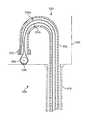
- FIG. 3Ais a perspective view of a surgical instrument.
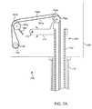
- FIG. 3Bis a perspective view of the distal portion of the surgical instrument shown in FIG. 3A .
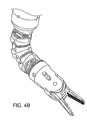
- FIGS. 4A and 4Bare perspective views of the wrist and end effector of the surgical instrument of FIGS. 3A and 3B .
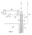
- FIG. 5is a cross-sectional view of a portion of a surgical instrument.
- FIG. 6is a cross-sectional view of a portion of another surgical instrument.
- FIGS. 7A and 7Bare cross-sectional views of portions of surgical instruments.
- FIG. 8is a cross-sectional view of a portion of another surgical instrument.
- FIGS. 9A and 9Bare cross-sectional views of portions of other surgical instruments.
- FIG. 10is a cross-sectional view of a housing for carrying a drive element.
- FIG. 11is a perspective view of a housing for carrying a drive element.
- FIGS. 12A and 12Bare perspective views of housings for carrying drive elements.
- FIG. 13is a cross-sectional view of a drive element for transmitting both compressive and tensile forces.
- FIG. 14Ais a perspective view of a housing for carrying a drive element.
- FIG. 14Bis a cross-sectional view of a housing and a drive element.
- FIG. 15is a cross-sectional view of another housing and a drive element.
- FIG. 16Ashows a perspective view
- FIG. 16Bshow a plan view, of a housing.
- FIG. 17is a cross-sectional view of a portion of a surgical instrument.
- FIG. 18Ais a cross-sectional view of an illustrative drive element and drive element housing
- FIG. 18Bis a cross-sectional view of a detail of FIG. 15A .
- FIG. 1is a simplified block diagram of a surgical system 100 , in accordance with embodiments of the present invention.
- the system 100includes a surgical assembly 110 mounted to or near an operating table 112 supporting a patient's body 122 .
- the surgical assembly 110enables the delivery of one or more surgical instruments 120 to a surgical site within the patient's body 122 .
- instrumentis used herein to describe a device configured to be inserted into a patient's body and used to carry out surgical procedures.
- the instrumentmay comprise a single surgical tool, such as a needle driver, a cautery device, or a cutting tool, an imaging device (e.g., an endoscope or ultrasound probe), or a combined device that includes a combination of two or more various tools and imaging devices.
- the system 100further includes a vision system 130 that enables the operator to view the surgical site from outside the patient's body 122 .
- the vision system 130may comprise, e.g., a video monitor displaying images received by an optical device provided at a distal end of one of the surgical instruments 120 .
- the optical devicemay comprise, e.g., a lens coupled to an optical fiber which carries the detected images to an imaging sensor (e.g., a CCD or CMOs sensor) outside of the patient's body 122 .
- the imaging sensormay be provided at the distal end of the surgical instrument 120 , and the signals produced by the sensor are transmitted along a lead or wirelessly for display on the monitor.
- An illustrative monitoris the stereoscopic display on the surgeon's cart in the da Vinci® Surgical System, manufactured by Intuitive Surgical, Inc., of Sunnyvale Calif.
- a control system 150is provided for controlling the insertion and articulation of the surgical assembly 110 and surgical instruments 120 .
- This controlmay be effectuated in a variety of ways, depending on the degree of control desired, the size of the surgical assembly 110 , and other factors.
- the control system 150may include one or more manually operated input devices, such as a joystick, exoskeletal glove, or the like. These input devices control servo motors which, in turn, control the articulation of the surgical assembly 110 .
- the forces generated by the servo motorsare transferred via drivetrain mechanisms, which transmit the forces from the servo motors generated outside the patient's body 122 through an intermediate portion of the elongate surgical assembly 110 to a portion of the surgical assembly 110 inside the patient's body 122 distal from the servo motor.
- the drivetrain mechanismmay comprise, e.g., cables in tension, or rods or tubes in compression or under torsion. Persons familiar with telemanipulative surgery will know of systems such as the da Vinci® Surgical System and the Zeus® system originally manufactured by Computer Motion, Inc. and various illustrative components of such systems.
- FIGS. 2A and 2Bare upper and lower perspective views, respectively, of a surgical assembly 110 inserted through, e.g., a single port 202 in a patient's abdomen (the entry guide cannula is not shown).
- the surgical assembly 110comprises an entry guide manipulator 210 and an instrument manipulator 220 .
- An entry guide 230is mounted onto the entry guide manipulator 210 , which includes a robotic positioning system for positioning the distal end 232 of the entry guide 230 at the desired target surgical site.
- the robotic positioning systemmay be provided in a variety of forms, such as, e.g., a serial link arm having multiple degrees of freedom (e.g., six degrees of freedom) or a remote center arm which is positioned by a setup joint mounted onto a base.
- the entry guide manipulator 210may be manually maneuvered so as to position the entry guide 230 in the desired location.
- the input devices that control the manipulator(s)may be provided at a location remote from the patient (outside the room in which the patient is placed).
- the input signals from the input devicesare then transmitted to the control system 150 , which, in turn, manipulates the manipulators 210 , 220 in response to those signals.
- the instrument manipulator 220is coupled to the entry guide manipulator 210 such that the instrument manipulator 220 moves in conjunction with the entry guide 230 .
- FIG. 3Ais a perspective view of an illustrative embodiment of the surgical instrument 120 , comprising an elongate body portion tube 310 , a distal portion 350 , and a proximal control mechanism 340 .
- FIG. 3Bis a perspective view of the distal portion 350 of the surgical instrument 120 in more detail.
- the distal portion 350comprises a first hinge mechanism 352 , a rigid forearm tube 353 , a second hinge mechanism 354 , a wrist assembly 320 , and an end effector 330 .
- the control mechanism 340includes a drive interface 342 , which mates with an instrument interface of a corresponding instrument manipulator 220 .
- a disposable interface mechanismmay be inserted between drive interface 342 and the instrument manipulator's instrument interface.
- the disposable interfacecan be used to facilitate sterile draping.
- the drive interface 342comprises a plurality of driven elements 344 , which are variously coupled via one or more drive train assemblies through the control mechanism 340 and body portion 310 to hinge assemblies 353 , 354 , wrist assembly 320 , and end effector 330 provided at the distal end of the instrument 120 .
- the drive trainsare not necessarily separate, and in one embodiment are coupled so that moving pairs of driven elements 344 moves a distal end component.
- the body portion 310is rotatably coupled to the control mechanism 340 to enable rotational displacement of the body portion 310 relative to the control mechanism 340 , as indicated by arrows H.
- at least one drive element 344is associated with rotating body 310 .
- FIGS. 4A and 4Bare perspective views of the wrist assembly 320 and end effector 330 of the surgical instrument 120 , with the end effector 330 in closed and open positions, respectively.
- the wrist assembly 320includes a first or proximal link 412 , which functions as an adaptor that couples the wrist assembly to the distal end of the body portion 310 , a second link 413 , a third or middle link 414 , a fourth link 415 , and a fifth or distal link 416 , which functions to couple the wrist assembly to the end effector.
- End effector 330includes gripper clevis 420 , which is coupled to distal link 416 .
- Clevis 420supports a pair of working members or jaws 422 , 424 .
- the jaws 422 , 424are rotatably supported by the gripper clevis 420 to rotate around pivot pin 426 .
- the jaws 422 , 424 shownare merely illustrative, and in other embodiments other types of end effectors, such as scissors, may be used.
- Drive elements(not shown, but similar to those described in U.S. Pat. No. 6,817,974) are used to transmit actuating forces from control mechanism 340 to the components at instrument 120 's distal end.
- Drive elementsmay be made in whole or in part of “filars” or filar-like components (the term “filars” as used herein should be broadly construed to include cables, hypotubes, single wires or rods (essentially similar at small diameters), various cable/wire/hypotube combinations, and any other long, thin component).
- a first set of drive elementsactuates the wrist mechanism. Wrist actuation cables extend through adjacent sets of apertures in the links in the wrist mechanism.
- the free ends of the cablesextend proximally through distal portion 350 and body portion 310 and are coupled at control mechanism 340 to driven elements 344 .
- a second set of one or more drive elementsare used to move the end effector 330 .
- Each of the links 412 - 416 in the wristhas a hole in its center, and together the holes in the links define a central lumen in the wrist assembly.
- the second set of drive elementspass from the end effector working member(s) (e.g., gripping jaws), through the central lumen formed by the annular links 412 - 416 , through distal portion 350 , and through the body portion 310 to the control mechanism 340 , where these cables are manipulated based upon the inputs to the driven elements 344 .
- one or more drive elementspass through an intermediate joint region (e.g., wrist assembly 320 , hinge mechanisms 352 , 354 ) to extend to and move a movable mechanism (e.g., end effector 330 ) that is distal of the intermediate joint region.
- a drive element housingthat also extends through the intermediate joint region.
- a forceis applied to the drive element housing that is opposite to the actuating force on the drive elements.
- the opposite drive element and drive element housing forcescombine so as to reduce the amount of force applied to the intermediate joint region when actuating the articulating mechanism.
- drive forcesare received by the driven elements 344 in control mechanism 340 at the proximal end of the instrument 120 .
- These forcesare transmitted by actuator assemblies inside control mechanism 340 to the movable, actuatable parts (e.g., instrument body, joints, wrist, end effector) of the instrument 120 .
- movable, actuatable partse.g., instrument body, joints, wrist, end effector
- Various mechanismscan be used, as described in more detail below.
- FIG. 5is a diagrammatic cross-sectional view of a portion of surgical instrument 500 and a portion of its control mechanism 540 .
- an actuator assembly 550 for a moveable distal component of instrument 500includes a cable 554 (a drive element). Two portions 554 a , 554 b (drive elements) of cable 554 run through a housing 552 (the drive element housing). The distal ends of cables 554 a , 554 b are attached to and move the end effector (not shown).
- the actuator assembly 550also includes a capstan 530 , which is coupled to (e.g., with gears) and is driven by one of the driven elements 344 ( FIG. 3A ). As depicted in FIG.
- cable 554is looped around capstan 530 . Therefore, cable portions 554 a and 554 b move in opposite directions within housing 552 as capstan 530 rotates. In this illustrative embodiment, only a tensile actuating force is applied by one of the cables 554 a , 554 b.
- housing 552As shown in FIG. 5 , the proximal end of housing 552 is anchored to the chassis of the control mechanism 540 with anchor 542 .
- the distal end (not shown) of housing 552rests against a distal component being actuated by cables 554 a , 554 b .
- the cable ends 554 a , 554 bare in contact with the inner wall of the curve in housing 552 .
- the end 554 a , 554 bapplies a force to the inner surface of the curve in housing 552 .
- anchor 542 and the distal component being actuatedapply opposing forces to the housing 552 .
- the forces applied by the cable 554 onto the inner wall of the housing 552are offset by the forces being applied to the housing 552 by the anchor 542 and the distal component.
- any intermediate structures through which the actuator assembly 550 passesare not affected by the forces being applied to the cable 554 .
- Aspects of the actuator assembly's drive element and drive element housing, which extend through the instrument's movable intermediate structures,are discussed in more detail below.
- the two ends 554 a , 554 bmay be carried in separate housings to the end effector.
- two separate cablesmay be used to actuate movement of the end effector, rather than the two ends of a single cable.
- the bend angleis the total amount of bending that the drive element experiences between the capstan and the distal component being actuated.
- the bend anglemay vary in other embodiments, depending on component placement.
- FIG. 6is a cross-sectional view of a portion of a surgical instrument 600 , in accordance with another embodiment.
- the actuator assembly 650includes a cable 654 (drive element) contained in a housing 652 (drive element housing).
- Actuator assembly 650also includes a capstan 630 , which is coupled to one of the driven elements 344 in control mechanism 640 .
- Cable 654wraps around capstan 630 .
- the two ends 654 a , 654 b of cable 654engage a pair of idler pulleys 660 a , 660 b , which are anchored to the proximal end of drive element housing 652 .
- Each cable end 654 a , 654 bruns over its associated idler pulley 660 a , 660 b before it enters drive element housing 652 .
- the drive element housing 652has a slight bend at its proximal end.
- the remainder of the bend angle for the cables 654 a , 654 bis provided by the idler pulleys 660 a , 660 b , thereby providing a total bend angle of greater than 90 degrees.
- the cable 554experiences some degree of friction with the housing 552 because the actuator assembly 550 is bent 180 degrees.
- the use of the pulleyse.g., idler pulleys 660 a , 660 b in FIG. 6 ) can reduce the friction experienced by the cable.
- a single pair of pulleys 660 a , 660 bmay be used. Nevertheless, if the housing 652 is straight, a pair of pulleys may be used to establish a bend angle of 90 degrees. It can be seen that as a tensile force is applied to one of the actuator cables 654 a , 654 b , its associated idler pulley 660 a , 660 b applies an approximately opposite force on the proximal end of drive element housing 652 . The force on drive element housing 552 is transmitted to the component being actuated at the distal end of the drive element housing. As described before, the opposite drive element and drive element housing forces on the distal component being actuated, while not equal, may effectively reduce or eliminate interfering forces on any intermediate joints through which the forces are transmitted.
- FIG. 7Ais a cross-sectional view of a portion of another surgical instrument 700 .
- the actuator assembly 750includes a cable 754 , which partially runs in a housing 752 , and a capstan 730 , which is rotatably coupled to the chassis of the control mechanism 740 and is driven by one of the driven elements of the drive interface of the control mechanism 740 .
- actuator assembly 750includes a support link 770 , which has a proximal end rotatably coupled at first pivot point 772 to the chassis for the control mechanism 740 .
- the distal end of the rotatable support link 770supports the proximal end of the housing 752 such that the housing 752 is free to translate axially (i.e., along the longitudinal axis) through the elongate body portion 710 .
- the support link 770further supports a first pair of idler pulleys 760 a , 760 b , which receive the two ends 754 a , 754 b of the cable 754 .
- the two ends 754 a , 754 b of the cable 754form a wrap angle of at least 90 degrees around the pulleys 760 a , 760 b , respectively. In this embodiment, the wrap angle is exactly 90 degrees.
- a cable support structureapplies a small amount of force to the cable 754 to maintain tension in the cable 754 between the first pair of pulleys 760 a , 760 b and the capstan 730 .
- the cable support structurecomprises a second pair of pulleys 762 a , 762 b , which are resiliently mounted to the chassis for the control mechanism 740 (e.g., using a spring 764 ).
- the cable support structuremay be provided with a maximum compliance such that when the cable 754 is under tension, the cable support structure will compress to the maximum compliance and then stop. Therefore, the compression compliance is minimized.
- the cable support structurewill maintain some minimal tension in order to prevent the cable 754 from slipping off the pulleys 760 a - 760 b.
- the support link 770Because the support link 770 is movably mounted within the control mechanism 740 and supports both the cable housing 752 and the cable 754 , the support link 770 applies a compressive force to the cable housing 752 substantially equal to the tensile force being applied by the idler pulleys 760 a , 760 b on the cable 754 .
- This application to the housing of an equal and opposite force as the force applied to the cableresults in a substantially zero net force on the intermediate structures between the input force and the structure being actuated (e.g., no net force applied to the wrist assembly 320 when the end effector 330 is being actuated).
- very high forcescan be transmitted to the actuated structure without causing unwanted articulation of the intermediate structures.
- the support linkmay be used to apply a force onto the housing that is less than the force applied to the cable. Although this will not ensure a substantially zero net force, as in FIG. 7 , this counterforce may be sufficient to prevent the unwanted articulation of the intermediate structures.
- the support link 770is rotatably mounted to the chassis of control mechanism 740 .
- other mechanisms permitting relative movement between the support link 770 and the input forcee.g., capstan 730
- the support link 770 ′is slidably mounted to a pair of rails 771 a , 771 b rather than being rotatably mounted to the first pivot point 772 .
- the drive element or elementsneed not be cables under tensile force.
- a single drive element that transmits both compressive and tensile forcesmay be used.
- a rigid shaft, solid or hollow, of various cross-sectional shapes or a wiremay be used.
- a cablemay be placed within a close fitting housing that prevents buckling so that the cable can transmit a compressive force.
- the drive element housingneed not completely surround the drive element.
- housingis merely an illustrative term and encompasses other components (e.g., a shaft) that perform a similar function of transmitting a force, opposite to the direction of an actuating force for a distal instrument component, to the distal instrument component.
- FIG. 8is a cross-sectional view of a portion of a surgical instrument 800 having an illustrative single drive element 854 transmitting both compressive and tensile forces.
- the drive element 854is a rod or a cable contained in a close-fitting drive element housing 852 that prevents the cable from buckling.
- a support link 870has a proximal end rotatably coupled to the chassis for the control mechanism 840 at first pivot point 872 and a distal end supporting the proximal end of the housing 852 , such that the housing 852 is free to translate axially through the elongate instrument body portion 810 .
- the rotational input force applied to the driven element 344 ( FIG. 3 ) of the control mechanism 840is transmitted to an input link 864 .
- a distal end of the input link 864is rotatably coupled to a proximal end of a coupling link 862 .
- the distal end of the coupling link 862is rotatably coupled to a proximal end of an L-shaped class 1 lever 860 .
- the distal end of the lever 860is rotatably coupled to the drive element 854 and an intermediate portion of the lever 860 is rotatably coupled to a second pivot point 874 (the fulcrum) on the support link 870 .
- the force applied by lever 860 at its fulcrum 874causes lever 870 to act as a class 3 lever with a fulcrum at 872 .
- Rotational movement of the link 864 due to the input forceis transferred by the coupling link 862 to cause rotation of the lever 860 about the second pivot point 874 .
- This rotationcauses the drive element 854 to translate axially through the housing 852 .
- the second pivot point 874applies a roughly equal and opposite force on the support link 870 as is applied to the drive element 854 .
- the input link 864is rotated in the clockwise direction, this causes the lever 860 to rotate about the second pivot point 874 and apply a compressive force onto the drive element 854 in the insertion (towards the distal end) direction, I.
- the second pivot point 874causes the support link 870 to rotate in a counterclockwise direction, which applies a tensile force on the housing 852 in the withdrawal (towards the proximal end) direction, W.
- the net force on the intermediate structuresapproaches zero.
- the second pivot point 874may be desirable for the second pivot point 874 to be a close as possible to the drive element 854 such that this distance is small relative to the distance between the second pivot point 874 and the first pivot point 872 . This positioning will ensure that the forces on the support link 870 are a close as possible to the opposite forces applied to the drive element 854 . It can be seen that if link 864 is pivoted in the opposite direction, actuator assembly 850 similarly causes a tensile force on drive element 854 and a compressive force on drive element housing 852 .
- FIG. 9Ais a cross-sectional view of a portion of a surgical instrument 900 having a single drive element 954 that transmits both compressive and tensile actuating forces to a movable distal end component, in accordance with another embodiment of the present invention.
- Drive element 954is contained in a drive element housing 952 that extends through the instrument body (not shown) and an intermediate moveable structure (not shown).
- a support link 970has a proximal end rotatably coupled to the chassis for the control mechanism 940 at first pivot point 972 and a distal end that supports the proximal end of housing 952 . As shown in FIG.
- connection between support link 970 and drive element housing 952is such that the housing 952 rotatably supports (e.g., with a bearing) the proximal end of the support link 970 .
- the illustrative figureshows that the proximal end of drive element housing is slightly concave and fits within a mating convex-edged hole in link 970 .
- This connectionallows drive element housing 952 to rotate around its longitudinal axis but not move longitudinally with reference to link 970 .
- link 970can apply a tensile or compressive force to drive element housing 952 while drive element housing 952 rotates within link 970 .
- Capstan 930is positioned within an elongated opening 934 of an input link 964 .
- the opening 934allows the input link 964 to slide linearly relative to the capstan 930 .
- a cable 932is coupled to the input link 964 and engages the capstan 930 so that rotational movement of the capstan 930 results in linear translation of the input link 964 in the W and I directions, depending on the direction of rotation.
- the cable 932may be omitted and the capstan 930 directly coupled to the input link 964 (e.g., rack and pinion or other gearing or a crank) to actuate linear movement of the input link 964 .
- the distal end of the input link 964is rotatably coupled to a proximal end of a lever 960 at third pivot point 966 .
- the distal end of the lever 960is coupled to the drive element 954 by a collar 962 .
- An intermediate portion of the lever 960is rotatably coupled to a second pivot point 974 (fulcrum) on the support link 970 .
- the third pivot point 966 and the first pivot point 972may be desirable to position the third pivot point 966 and the first pivot point 972 at equal distances from the second pivot point 974 so that pulling on input link 964 does not create a moment on the support link 970 .
- the force F on the drive element 954equals that at third pivot point 966 , so that 2F is applied at the second pivot point 974 .
- this 2F forceis split evenly between the first pivot point 972 and the housing 952 , so that F is applied equally and oppositely to the housing 952 .
- the second pivot point 974may be located at a point other than the midway point between the third pivot point 966 and the collar 962 . If the third pivot point 966 and the first pivot point 972 are at equal distances from the second pivot point 974 , then the forces at the third pivot point 966 and the collar 962 would no longer be equal, but they would be unequal in the same proportion as the forces at the first pivot point 972 and the housing 952 . Thus, the drive element and drive element housing forces would still be opposite.
- the rotational input force from 344results in rotational movement of the capstan 930 .
- This movementcauses the input link 964 to translate linearly.
- Upward movement of the third pivot point 966causes the lever 960 rotate about the second pivot point 974 , thereby causing the distal end of the lever 960 to apply a compressive force on the drive element 954 .
- downward movement of the third pivot point 966causes the distal end of the lever 960 to apply a tensile force on the drive element 954 .
- the coupling of the lever 960 to the support link 970causes the distal end of the support link 970 to apply a force to the housing 952 in the opposite direction as the force being applied to the driving element 954 .
- the location of the second pivot point 974 along the length of the support link 970determines the ratio of the input force to end effector actuation force.
- the second pivot point 974is located exactly between the first pivot point 972 and the housing 952 .
- This embodimentmay advantageously decouple the input force from joint movement of the driving element 954 and housing 952 .
- This decouplingensures that the input force effectively actuates relative movement between the driving element 954 and the housing 952 , yet is not affected when the driving element 954 and housing 952 are jointly acted upon by external forces (such as, e.g., when the wrist assembly 320 is articulated).
- external forcessuch as, e.g., when the wrist assembly 320 is articulated.
- movement of the wrist assembly 320will not affect grip position, and the grip movement and grip force will not affect the position of the wrist assembly 320 .
- the movement of the jointscan then be controlled more smoothly and accurately.
- FIG. 9Bis a cross-sectional view of a portion of a surgical instrument 900 ′, similar to the surgical instrument 900 described above with respect to FIG. 9A , but including a radial ball bearing to support the housing 952 ′ axially while enabling rotation of the housing 952 ′.
- the actuator assembly used to actuate movement of the end effector or other distal end component of the instrumentmay be provided in a variety of forms, depending on the application.
- the actuator assemblyshould be capable of operation regardless of the extent of articulation of intermediate joint regions. Therefore, the bend angle and bend radius of the intermediate joint regions should be one factor in selecting the drive element and drive element housing for the actuator assembly.
- the drive element and drive element housingmust accommodate such rotation. In one exemplary embodiment the instrument body rotates approximately 270 degrees in either direction.
- the drive element's small diameteraccommodates the twist from this rotation.
- the drive element housingmay be too stiff to accommodate the twist, and so one or more rotating joints as described above with reference to link 970 ( FIG. 9 ) or below in FIG. 10 are used to accommodate the instrument body rotation.
- a conventional spring windmay be used for the drive element housing.
- bending of a spring wind housingmay result in a change in overall length of the actuator assembly. This change may be undesirable if the intermediate joints are configured for significant range of motion.
- a drive element housingis provided that is capable of accommodating relative rotation of the proximal and distal ends of the housing, while being able to transmit compressive and tensile forces.
- FIG. 10shows one example of a drive element housing 1000 for carrying a drive element, such as a cable.
- the housing 1000comprises a first cylindrical portion 1010 and a second cylindrical portion 1020 , which are coupled at a coupling portion 1030 .
- Coupling portion 1030permits relative rotation between the first and second portions 1010 , 1020 .
- the coupling portion 1030comprises a first enlarged portion 1040 of the first cylindrical portion 1010 received within a second enlarged portion 1050 of the second cylindrical portion 1020 .
- a sufficient clearance gap Gis provided between the second enlarged portion 1050 and the first enlarged portion 1040 so as to enable the first enlarged portion 1040 to rotate within the second enlarged portion 1050 .
- the inner diameter of the second enlarged portion 1050reduces on either side of the first enlarged portion 1040 so as to prevent significant relative movement in the direction of the longitudinal axis, between the first portion 1010 and the second portion 1020 .
- the first portion 1010comprises a 0.027-inch ID ⁇ 0.03-inch OD tube
- the second portion 1020comprises a 0.042-inch ID ⁇ 0.058-inch OD tube.
- the first enlarged portion 1040comprises an annular ring of 0.035-inch ID ⁇ 0.042-inch OD.
- FIG. 11shows another example of a drive element housing 1100 .
- the housing 1100comprises a hollow tube 1110 of 302 stainless steel having a plurality of longitudinal slits 1120 .
- These slits 1120are provided in one or more sets (e.g., sets 1131 and 1132 ), each set comprising a series of slits 1120 provided at various radial positions around the circumference of the tube 1110 .
- These slits 1120enable the tube 1110 to twist at the locations of the slits 1120 while maintaining axial stiffness so as to transmit tensile and compressive forces.
- this embodimentprovides an alternate way to accommodate rotation of the housing 1100 .
- the size and location of the slits 1120may be varied, depending on the application.
- the slits 1120may be provided at equally spaced locations around the circumference of the housing 1100 .
- the slits 1120can be a few thousandths of an inch wide such that the metal remaining between the slits 1120 forms rods 0.008-inches wide and 0.15-inches long.
- the linear longitudinal slits 1120 shown in FIG. 11may be used to accommodate twisting as the instrument rolls.
- slits formed in a helical patternmay be provided in the housing to accommodate bending of the housing at the location of the slits. Any shortening of tube 1110 due to the twisting is negligible.
- FIG. 12Ashows yet another example of a drive element housing 1200 .
- the housing 1200comprises a plurality of wires 1210 arranged to form a tube.
- the housing 1200may comprise twenty wires 1210 , each having a diameter of 0.008-inches. These wires 1210 may be coupled together at multiple coupling regions 1220 along the length of the housing 1200 . These coupling regions 1220 may comprise, e.g., weld points where the wires 1210 are welded together. This structure may provide good stiffness in tension and compression while permitting some torsion, which can be adjustable based on selection of the wires 1210 and the spacing of the coupling regions 1220 .
- the wires 1210may comprise, e.g., 302 stainless steel or a nickel-titanium (NiTi) alloy (e.g., Nitinol).
- Nitinolmay be desirable for its “superelastic” behavior, enabling the material to maintain its shape even after a 2-percent or even 8-percent strain.
- each coupling region 1220comprises a solid metal cylinder having longitudinal holes formed in the wall of the cylinder to enable the wires 1210 to pass through. Plastic spacers inside the diameter of the wires keep the spacers from sliding along the wires.
- FIG. 12Bshows another drive element housing 1250 that includes a plurality of wires 1210 .
- a flexible coupling material 1230such as a polymer, is extruded over the wires 1210 .
- the flexible coupling material 1230is used to prevent buckling of the wires 1210 when the housing 1250 is under a compressive axial load.
- FIG. 13shows an illustrative embodiment of a drive element 1300 that may be used to transmit both compressive and tensile forces to the end effector.
- drive element 1300comprises a central core 1310 , which provides tensile strength, such as 0.018-inch diameter tungsten cable.
- the drive element 1300comprises an outer layer 1320 , which contains the tungsten core 1310 and provides the drive element 1300 with the ability to transmit compressive forces.
- the outer layer 1320comprises a second cable 1322 wrapped around the core 1310 in a spring-wind fashion.
- the outer surface of the outer cable 1322is ground down to form a flat surface 1324 to minimize friction and snagging with the interior of the drive element housing that carries the drive element 1300 .
- These designsare similar to how the housings are sometimes produced for bicycle brake (flat wound rectangular wire) and shift (substantially parallel wires with a polymer liner) mechanisms.
- FIGS. 14A and 14Billustrate yet another drive element housing 1400 that may be used to carry the drive element 1300 .
- This housing 1400is formed from a ribbon-shaped wire having a rectangular cross-section, as can be seen in FIG. 14B , and wound in a helix, as can be seen in FIG. 14A .
- the spring-wind structure of the housing 1400enables the housing 1400 to bend at the intermediate joint regions, and the rectangular cross-section enables the housing 1400 to better transmit tensile forces than a round wire spring-wind housing.
- a plastic sheath 1410may be provided over the ribbon-shaped wire so as to reduce friction between the housing 1400 and the passages through which the housing 1400 passes.
- FIG. 15depicts another illustrative drive element housing 1500 that may be used to carry the drive element 1300 .
- the drive element housing 1500is a Nitinol tube 1510 having a plurality of slits 1520 formed only in the regions of the housing 1500 that correspond to the intermediate joint regions through which housing 1500 passes.
- these slits 1520are formed at an angle to the longitudinal axis of the housing 1500 (i.e., angled kerf cuts that penetrate to the tube's hollow center) and in a direction different from the winding of the cable 1322 . This opposite angling can prevent the spring wind cable 1322 from snagging on the slits 1520 while providing the housing 1500 with flexibility for bending in the joint regions of the instrument.
- FIG. 16Ashows a perspective view
- FIG. 16Bshows a plan view, of still another illustrative drive element housing 1600 .
- the housing 1600is a solid nitinol tube 1610 having a plurality of shaped apertures 1620 formed in the walls of the tube 1610 (e.g., dovetail-shaped kerf cuts that penetrate to the tube's hollow center, as shown).
- This drive element housing 1600 configurationprovides good tensile strength and enables housing 1600 to be bent in a tight radius.
- the apertures 1620form longitudinal portions 1630 and connecting portions 1640 in the tube 1610 .
- the longitudinal portions 1630provide axial stiffness to the housing 1600 and are provided at locations offset by 90 degrees around the circumference of the tube 1610 . This enables the housing 1600 to bend at the locations of the apertures 1620 in any direction.
- the overall strength of the tube 1610can approximate that of a 0.018′′ tungsten cable.
- FIG. 17is a cross sectional view of a distal portion of a surgical instrument that illustrates how the drive element and drive element housing are positioned at the region where the wrist assembly 320 is coupled to the end effector 320 .
- Distal link 416is coupled to gripper clevis 420 as shown.
- Drive element housing 1752extends through wrist assembly 320 and is braced against end effector 330 's gripper clevis 420 .
- Drive element 1754extends through drive element housing 1752 and is coupled to operate end effector 330 's jaws.
- An annular collar 1753is coupled to the distal end of drive element housing 1752 .
- annular collar 1753is a segment of Nitinol tubing (0.031-inch ID ⁇ 0.041-inch OD) welded over drive element housing 1752 .
- flange 1756is positioned between the gripper clevis 420 and the distal link 416 .
- the collar 1753is positioned between the flange 1756 and the gripper clevis 420 to prevent motion of drive element housing 1752 along the longitudinal axis.
- flange 1756applies the force to the distal link 416 of wrist assembly 320 .
- a compressive forceis applied to the housing 1752
- the collar 1753applies the compressive force to the gripper clevis 420 . As described above, these forces help counteract forces being applied by drive element 1754 .
- FIG. 18Ais a partial cross-sectional view of an illustrative drive element and drive element housing combination
- FIG. 18Bis a cross-sectional view of a detail of FIG. 18 A.
- the combinationincludes two sections.
- the combination's first section 1802is the distal section.
- This distal section 1802runs through wrist assembly 320 in instrument 120 s distal portion 350 .
- the combination's proximal section 1804(only a portion is shown) runs through the substantially rigid portion of the instrument body as described above.
- both the distal and proximal sections 1802 , 1804have a drive element and drive element housing.
- cross pin member 1806attaches to the movable part or parts (e.g., gripper jaws) of the end effector.
- Distal drive element portion 1808 ais coupled to cross pin member 1806 and extends through distal drive element housing portion 1810 a .
- distal drive element portion 1808 ais a 0.016-inch Nitinol wire (not heat treated, but 40 percent cold worked).
- Distal drive element housing portion 1810 ais a 0.020-inch ID ⁇ 0.030-inch OD Nitinol tube. Since the Nitinol tube's diameter is small, it accommodates the wrist bending.
- proximal drive element portion 1808 bextends through proximal drive element housing portion 1810 b .
- proximal drive element portion 1808 bis a 0.017-inch ID ⁇ 0.035-inch OD 302 stainless steel hypotube. Due to the difficulty in purchasing 0.017-inch ID ⁇ 0.035-inch OD 302 stainless steel hypotubes, the proximal drive element portion 1808 b may be formed by fitting a 0.017-inch ID ⁇ 0.025-inch OD hypotube inside of a 0.0275-inch ID ⁇ 0.0355-inch OD hypotube.
- Proximal drive element housing portion 1810 ais a rigid 0.042-inch ID ⁇ 0.058-inch OD 302 stainless steel hypotube. Stainless steel rather than Nitinol hypotubes are used due to decreased cost and increased stiffness.
- Distal and proximal drive elements 1808 a , 1808 bare joined by, e.g., crimping. Since the outer diameter of distal drive element housing portion 1810 a is smaller than the inner diameter of proximal drive element housing portion 1810 b , a stainless steel tube 1812 is inserted between the drive element housing portions 1810 a , 1810 b and is secured by, e.g., crimping or welding. To allow for drive element movement, the distal end of proximal drive element portion 1808 b is set back a distance D from the proximal end of tube 1812 . The distance D is made large enough to allow for full actuation but small enough to prevent distal drive element portion 1808 a from buckling under compression before entering distal drive element housing 1810 a.
- Embodiments of the present inventionmay provide various advantages not provided by prior art systems. For example, embodiments may enable a surgical instrument to provide balanced force actuation to a distal articulating mechanism through a joint region capable of a large range of motion.
- the drive elementspass through a first joint region (e.g., the wrist assembly) to manipulate the end effector.
- the drive elements which pass through the first joint regionmay be used to manipulate other articulating mechanisms, such as additional joints or wrist assemblies.
Landscapes
- Health & Medical Sciences (AREA)
- Surgery (AREA)
- Engineering & Computer Science (AREA)
- Life Sciences & Earth Sciences (AREA)
- Biomedical Technology (AREA)
- Robotics (AREA)
- Nuclear Medicine, Radiotherapy & Molecular Imaging (AREA)
- Heart & Thoracic Surgery (AREA)
- Medical Informatics (AREA)
- Molecular Biology (AREA)
- Animal Behavior & Ethology (AREA)
- General Health & Medical Sciences (AREA)
- Public Health (AREA)
- Veterinary Medicine (AREA)
- Surgical Instruments (AREA)
Abstract
Description
- U.S. patent application Ser. No. 11/762,217 entitled “Retraction of tissue for single port entry, robotically assisted medical procedures” by Mohr;
- U.S. patent application Ser. No. 11/762,222 entitled “Bracing of bundled medical devices for single port entry, robotically assisted medical procedures” by Mohr et al.;
- U.S. patent application Ser. No. 11/762,231 entitled “Extendable suction surface for bracing medical devices during robotically assisted medical procedures” by Schena;
- U.S. patent application Ser. No. 11/762,236 entitled “Control system configured to compensate for non-ideal actuator-to-joint linkage characteristics in a medical robotic system” by Diolaiti et al.;
- U.S. patent application Ser. No. 11/762,165 entitled “Minimally invasive surgical system” by Larkin et al.;
- U.S. patent application Ser. No. 11/762,161 entitled “Minimally invasive surgical instrument advancement” by Larkin et al.;
- U.S. patent application Ser. No. 11/762,158 entitled “Surgical instrument control and actuation” by Cooper et al.;
- U.S. patent application Ser. No. 11/762,154 entitled “Surgical instrument with parallel motion mechanism” by Cooper;
- U.S. patent application Ser. No. 11/762,149 entitled “Minimally invasive surgical apparatus with side exit instruments” by Larkin;
- U.S. patent application Ser. No. 11/762,170 entitled “Minimally invasive surgical apparatus with side exit instruments” by Larkin;
- U.S. patent application Ser. No. 11/762,143 entitled “Minimally invasive surgical instrument system” by Larkin;
- U.S. patent application Ser. No. 11/762,135 entitled “Side looking minimally invasive surgery instrument assembly” by Cooper et al.;
- U.S. patent application Ser. No. 11/762,132 entitled “Side looking minimally invasive surgery instrument assembly” by Cooper et al.;
- U.S. patent application Ser. No. 11/762,127 entitled “Guide tube control of minimally invasive surgical instruments” by Larkin et al.;
- U.S. patent application Ser. No. 11/762,123 entitled “Minimally invasive surgery guide tube” by Larkin et al.;
- U.S. patent application Ser. No. 11/762,120 entitled “Minimally invasive surgery guide tube” by Larkin et al.;
- U.S. patent application Ser. No. 11/762,118 entitled “Minimally invasive surgical retractor system” by Larkin;
- U.S. patent application Ser. No. 11/762,114 entitled “Minimally invasive surgical illumination” by Schena et al.;
- U.S. patent application Ser. No. 11/762,110 entitled “Retrograde instrument” by Duval et al.;
- U.S. patent application Ser. No. 11/762,204 entitled “Retrograde instrument” by Duval et al.;
- U.S. patent application Ser. No. 11/762,202 entitled “Preventing instrument/tissue collisions” by Larkin;
- U.S. patent application Ser. No. 11/762,189 entitled “Minimally invasive surgery instrument assembly with reduced cross section” by Larkin et al.;
- U.S. patent application Ser. No. 11/762,191 entitled “Minimally invasive surgical system” by Larkin et al.;
- U.S. patent application Ser. No. 11/762,196 entitled “Minimally invasive surgical system” by Duval et al.; and
- U.S. patent application Ser. No. 11/762,200 entitled “Minimally invasive surgical system” by Diolaiti.
Claims (23)
Priority Applications (1)
| Application Number | Priority Date | Filing Date | Title |
|---|---|---|---|
| US11/762,172US8597280B2 (en) | 2006-06-13 | 2007-06-13 | Surgical instrument actuator |
Applications Claiming Priority (2)
| Application Number | Priority Date | Filing Date | Title |
|---|---|---|---|
| US81312906P | 2006-06-13 | 2006-06-13 | |
| US11/762,172US8597280B2 (en) | 2006-06-13 | 2007-06-13 | Surgical instrument actuator |
Publications (2)
| Publication Number | Publication Date |
|---|---|
| US20080058861A1 US20080058861A1 (en) | 2008-03-06 |
| US8597280B2true US8597280B2 (en) | 2013-12-03 |
Family
ID=39152870
Family Applications (1)
| Application Number | Title | Priority Date | Filing Date |
|---|---|---|---|
| US11/762,172Active2031-05-19US8597280B2 (en) | 2006-06-13 | 2007-06-13 | Surgical instrument actuator |
Country Status (1)
| Country | Link |
|---|---|
| US (1) | US8597280B2 (en) |
Cited By (144)
| Publication number | Priority date | Publication date | Assignee | Title |
|---|---|---|---|---|
| US20140057378A1 (en)* | 2008-08-19 | 2014-02-27 | Samsung Display Co., Ltd. | Organic light emitting display apparatus and method of manufacturing organic light emitting display apparatus |
| US9814527B2 (en) | 2009-09-23 | 2017-11-14 | Intuitive Surgical Operations, Inc. | Cannula mounting fixture |
| US9931173B2 (en) | 2009-09-23 | 2018-04-03 | Intuitive Surgical Operations, Inc. | Curved cannula surgical system |
| US9949800B2 (en) | 2009-09-23 | 2018-04-24 | Intuitive Surgical Operations, Inc. | Curved cannula surgical system control |
| US20180242991A1 (en)* | 2015-08-28 | 2018-08-30 | Distalmotion Sa | Surgical instrument with increased actuation force |
| US10245069B2 (en) | 2009-09-23 | 2019-04-02 | Intuitive Surgical Operations, Inc. | Surgical port feature |
| WO2020102776A1 (en)* | 2018-11-15 | 2020-05-22 | Intuitive Surgical Operations, Inc. | Surgical instrument with sensor aligned cable guide |
| WO2020131692A1 (en) | 2018-12-21 | 2020-06-25 | Intuitive Surgical Operations, Inc. | Surgical instruments having mechanisms for identifying and/or deactivating stapler cartridges |
| WO2020131418A1 (en) | 2018-12-21 | 2020-06-25 | Intuitive Surgical Operations, Inc. | Actuation mechanisms for surgical instruments |
| WO2020131298A1 (en) | 2018-12-21 | 2020-06-25 | Intuitive Surgical Operations, Inc. | Surgical instruments having a reinforced staple cartridge |
| WO2020214258A1 (en) | 2019-04-15 | 2020-10-22 | Intuitive Surgical Operations, Inc. | Staple cartridge for a surgical instrument |
| WO2020242808A1 (en) | 2019-05-31 | 2020-12-03 | Intuitive Surgical Operations, Inc. | Staple cartridge for a surgical instrument |
| US10864049B2 (en) | 2014-12-19 | 2020-12-15 | Distalmotion Sa | Docking system for mechanical telemanipulator |
| US10980556B2 (en) | 2013-08-15 | 2021-04-20 | Intuitive Surgical Operations, Inc. | Rotary input for lever actuation |
| WO2021076371A1 (en) | 2019-10-18 | 2021-04-22 | Intuitive Surgical Operations, Inc. | Surgical instrument with adjustable jaws |
| US11007024B2 (en) | 2016-07-14 | 2021-05-18 | Intuitive Surgical Operations, Inc. | Geared grip actuation for medical instruments |
| US11026759B2 (en) | 2017-02-24 | 2021-06-08 | Intuitive Surgical Operations, Inc. | Splayed cable guide for a medical instrument |
| DE202021000992U1 (en) | 2021-03-05 | 2021-06-21 | lNTUITIVE SURGICAL OPERATIONS,INC. | Electrosurgical instruments for sealing and dissection |
| US11039820B2 (en) | 2014-12-19 | 2021-06-22 | Distalmotion Sa | Sterile interface for articulated surgical instruments |
| US11058503B2 (en) | 2017-05-11 | 2021-07-13 | Distalmotion Sa | Translational instrument interface for surgical robot and surgical robot systems comprising the same |
| US11076922B2 (en) | 2010-10-11 | 2021-08-03 | Ecole Polytechnique Federale De Lausanne (Epfl) | Mechanical manipulator for surgical instruments |
| DE202020004565U1 (en) | 2019-12-12 | 2021-08-05 | Intuitive Surgical Operations, Inc. | Electrosurgical instruments for sealing and dissection |
| US11118661B2 (en) | 2018-02-12 | 2021-09-14 | Intuitive Surgical Operations, Inc. | Instrument transmission converting roll to linear actuation |
| US11123145B2 (en) | 2016-04-29 | 2021-09-21 | Intuitive Surgical Operations, Inc. | Compliant mechanisms having inverted tool members |
| US11200980B2 (en) | 2011-07-27 | 2021-12-14 | Ecole Polytechnique Federale De Lausanne (Epfl) | Surgical teleoperated device for remote manipulation |
| US11202683B2 (en) | 2019-02-22 | 2021-12-21 | Auris Health, Inc. | Surgical platform with motorized arms for adjustable arm supports |
| US11207145B2 (en) | 2016-07-14 | 2021-12-28 | Intuitive Surgical Operations, Inc. | Multi-cable medical instrument |
| US11241290B2 (en) | 2016-11-21 | 2022-02-08 | Intuitive Surgical Operations, Inc. | Cable length conserving medical instrument |
| US11248686B2 (en) | 2013-08-15 | 2022-02-15 | Intuitive Surgical Operations, Inc. | Lever actuated gimbal plate |
| US11357526B2 (en) | 2011-05-13 | 2022-06-14 | Intuitive Surgical Operations, Inc. | Medical instrument with snake wrist structure |
| WO2022150212A1 (en) | 2021-01-08 | 2022-07-14 | Intuitive Surgical Operations, Inc. | Surgical instrument with linear and purse string suture staples |
| WO2022150215A1 (en) | 2021-01-08 | 2022-07-14 | Intuitive Surgical Operations, Inc. | Surgical stapling instruments |
| US11432891B2 (en) | 2015-06-03 | 2022-09-06 | Covidien Lp | Offset instrument drive unit |
| US11432836B2 (en) | 2016-09-14 | 2022-09-06 | Intuitive Surgical Operations, Inc. | Joint assemblies with cross-axis flexural pivots |
| US11432890B2 (en) | 2018-01-04 | 2022-09-06 | Covidien Lp | Systems and assemblies for mounting a surgical accessory to robotic surgical systems, and providing access therethrough |
| USD963851S1 (en) | 2020-07-10 | 2022-09-13 | Covidien Lp | Port apparatus |
| US11446099B2 (en) | 2016-06-03 | 2022-09-20 | Covidien Lp | Control arm for robotic surgical systems |
| US11464593B2 (en) | 2016-06-03 | 2022-10-11 | Covidien Lp | Passive axis system for robotic surgical systems |
| US11478315B2 (en) | 2014-12-19 | 2022-10-25 | Distalmotion Sa | Reusable surgical instrument for minimally invasive procedures |
| US11484372B2 (en) | 2019-02-15 | 2022-11-01 | Covidien Lp | Articulation mechanisms for surgical instruments such as for use in robotic surgical systems |
| US11497567B2 (en) | 2018-02-08 | 2022-11-15 | Intuitive Surgical Operations, Inc. | Jointed control platform |
| US11510745B2 (en) | 2018-02-07 | 2022-11-29 | Distalmotion Sa | Surgical robot systems comprising robotic telemanipulators and integrated laparoscopy |
| US11510747B2 (en) | 2017-05-25 | 2022-11-29 | Covidien Lp | Robotic surgical systems and drapes for covering components of robotic surgical systems |
| US11523509B2 (en) | 2016-05-26 | 2022-12-06 | Covidien Lp | Instrument drive units |
| US11517183B2 (en) | 2015-10-23 | 2022-12-06 | Covidien Lp | Surgical system for detecting gradual changes in perfusion |
| US11529203B2 (en) | 2015-09-25 | 2022-12-20 | Covidien Lp | Robotic surgical assemblies and instrument drive connectors thereof |
| US11540889B2 (en) | 2017-11-10 | 2023-01-03 | Intuitive Surgical Operations, Inc. | Tension control in actuation of jointed instruments |
| US11547508B2 (en) | 2016-05-26 | 2023-01-10 | Covidien Lp | Robotic surgical assemblies |
| US11553974B2 (en) | 2017-05-25 | 2023-01-17 | Covidien Lp | Systems and methods for detection of objects within a field of view of an image capture device |
| US11553984B2 (en) | 2016-06-03 | 2023-01-17 | Covidien Lp | Robotic surgical system with an embedded imager |
| US11576739B2 (en) | 2018-07-03 | 2023-02-14 | Covidien Lp | Systems, methods, and computer-readable media for detecting image degradation during surgical procedures |
| US11576562B2 (en) | 2016-04-07 | 2023-02-14 | Titan Medical Inc. | Camera positioning method and apparatus for capturing images during a medical procedure |
| US11576733B2 (en) | 2019-02-06 | 2023-02-14 | Covidien Lp | Robotic surgical assemblies including electrosurgical instruments having articulatable wrist assemblies |
| US11586106B2 (en) | 2018-12-28 | 2023-02-21 | Titan Medical Inc. | Imaging apparatus having configurable stereoscopic perspective |
| US11583358B2 (en) | 2017-09-06 | 2023-02-21 | Covidien Lp | Boundary scaling of surgical robots |
| US11596490B2 (en) | 2009-08-15 | 2023-03-07 | Intuitive Surgical Operations, Inc. | Application of force feedback on an input device to urge its operator to command an articulated instrument to a preferred pose |
| US11596489B2 (en) | 2015-03-10 | 2023-03-07 | Covidien Lp | Measuring health of a connector member of a robotic surgical system |
| US11602336B2 (en) | 2016-12-19 | 2023-03-14 | Intuitive Surgical Operations, Inc. | Sample retrieval tool with compliant retention member |
| US11612446B2 (en) | 2016-06-03 | 2023-03-28 | Covidien Lp | Systems, methods, and computer-readable program products for controlling a robotically delivered manipulator |
| US11615884B2 (en) | 2018-03-06 | 2023-03-28 | Digital Surgery Limited | Techniques for virtualized tool interaction |
| US11618171B2 (en) | 2013-12-11 | 2023-04-04 | Covidien Lp | Wrist and jaw assemblies for robotic surgical systems |
| US11622824B2 (en) | 2015-06-16 | 2023-04-11 | Covidien Lp | Robotic surgical system torque transduction sensing |
| US11628022B2 (en) | 2017-09-05 | 2023-04-18 | Covidien Lp | Collision handling algorithms for robotic surgical systems |
| US11628024B2 (en) | 2018-03-08 | 2023-04-18 | Covidien Lp | Surgical robotic systems |
| US11633243B2 (en) | 2018-10-10 | 2023-04-25 | Titan Medical Inc. | Instrument insertion system, method, and apparatus for performing medical procedures |
| US11638622B2 (en) | 2008-06-27 | 2023-05-02 | Intuitive Surgical Operations, Inc. | Medical robotic system providing an auxiliary view of articulatable instruments extending out of a distal end of an entry guide |
| US11638999B2 (en) | 2006-06-29 | 2023-05-02 | Intuitive Surgical Operations, Inc. | Synthetic representation of a surgical robot |
| US11647888B2 (en) | 2018-04-20 | 2023-05-16 | Covidien Lp | Compensation for observer movement in robotic surgical systems having stereoscopic displays |
| US11666395B2 (en) | 2015-06-23 | 2023-06-06 | Covidien Lp | Robotic surgical assemblies |
| US11690691B2 (en) | 2017-02-15 | 2023-07-04 | Covidien Lp | System and apparatus for crush prevention for medical robot applications |
| US11717361B2 (en) | 2017-05-24 | 2023-08-08 | Covidien Lp | Electrosurgical robotic system having tool presence detection |
| US11717355B2 (en) | 2019-01-29 | 2023-08-08 | Covidien Lp | Drive mechanisms for surgical instruments such as for use in robotic surgical systems |
| US11751955B2 (en) | 2007-06-13 | 2023-09-12 | Intuitive Surgical Operations, Inc. | Method and system for retracting an instrument into an entry guide |
| US11779413B2 (en) | 2015-11-19 | 2023-10-10 | Covidien Lp | Optical force sensor for robotic surgical system |
| US20230320795A1 (en)* | 2020-09-15 | 2023-10-12 | Covidien Lp | Surgical robotic system for controlling wristed instruments |
| US11806102B2 (en) | 2013-02-15 | 2023-11-07 | Intuitive Surgical Operations, Inc. | Providing information of tools by filtering image areas adjacent to or on displayed images of the tools |
| US11839441B2 (en) | 2017-05-25 | 2023-12-12 | Covidien Lp | Robotic surgical system with automated guidance |
| US11844585B1 (en) | 2023-02-10 | 2023-12-19 | Distalmotion Sa | Surgical robotics systems and devices having a sterile restart, and methods thereof |
| US11864851B2 (en) | 2016-07-14 | 2024-01-09 | Intuitive Surgical Operations, Inc. | Geared roll drive for medical instrument |
| US11865729B2 (en) | 2006-06-29 | 2024-01-09 | Intuitive Surgical Operations, Inc. | Tool position and identification indicator displayed in a boundary area of a computer display screen |
| US11925429B2 (en) | 2015-02-19 | 2024-03-12 | Covidien Lp | Repositioning method of input device for robotic surgical system |
| US11941734B2 (en) | 2009-03-31 | 2024-03-26 | Intuitive Surgical Operations, Inc. | Rendering tool information as graphic overlays on displayed images of tools |
| US11948226B2 (en) | 2021-05-28 | 2024-04-02 | Covidien Lp | Systems and methods for clinical workspace simulation |
| US11957371B2 (en) | 2014-08-13 | 2024-04-16 | Covidien Lp | Robotically controlling mechanical advantage gripping |
| US11963730B2 (en) | 2021-11-30 | 2024-04-23 | Endoquest Robotics, Inc. | Steerable overtube assemblies for robotic surgical systems |
| US11986261B2 (en) | 2018-04-20 | 2024-05-21 | Covidien Lp | Systems and methods for surgical robotic cart placement |
| US11992936B2 (en) | 2014-08-15 | 2024-05-28 | Intuitive Surgical Operations, Inc. | Surgical system with variable entry guide configurations |
| US11998288B2 (en) | 2018-09-17 | 2024-06-04 | Covidien Lp | Surgical robotic systems |
| US12029510B2 (en) | 2018-01-10 | 2024-07-09 | Covidien Lp | Determining positions and conditions of tools of a robotic surgical system utilizing computer vision |
| US12029523B2 (en) | 2017-12-01 | 2024-07-09 | Covidien Lp | Drape management assembly for robotic surgical systems |
| US12030195B2 (en) | 2020-05-27 | 2024-07-09 | Covidien Lp | Tensioning mechanisms and methods for articulating surgical instruments such as for use in robotic surgical systems |
| US12064196B2 (en) | 2021-11-30 | 2024-08-20 | Endoquest Robotics, Inc. | Master control systems for robotic surgical systems |
| US12097002B2 (en) | 2007-06-13 | 2024-09-24 | Intuitive Surgical Operations, Inc. | Medical robotic system with coupled control modes |
| US12102403B2 (en) | 2018-02-02 | 2024-10-01 | Coviden Lp | Robotic surgical systems with user engagement monitoring |
| US12114945B2 (en) | 2021-09-13 | 2024-10-15 | Distalmotion Sa | Instruments for surgical robotic system and interfaces for the same |
| WO2024215716A1 (en) | 2023-04-11 | 2024-10-17 | Intuitive Surgical Operations, Inc. | Surgical stapling instruments and control systems for such instruments |
| WO2024228981A1 (en) | 2023-05-01 | 2024-11-07 | Intuitive Surgical Operations, Inc. | Components of surgical stapling instruments and methods for manufacturing the same |
| US12138001B2 (en) | 2021-11-30 | 2024-11-12 | Endoquest Robotics, Inc. | Patient console 5-degree of freedom positioning systems |
| US12144537B2 (en) | 2017-08-16 | 2024-11-19 | Covidien Lp | End effector including wrist assembly and electrosurgical tool for robotic surgical systems |
| US12144571B2 (en) | 2021-11-30 | 2024-11-19 | Endoquest Robotics, Inc. | Force transmission systems for robotically controlled medical devices |
| WO2024242819A1 (en) | 2023-05-03 | 2024-11-28 | Intuitive Surgical Operations, Inc. | Surgical staple cartridge insertion and protection devices |
| WO2024249979A1 (en) | 2023-06-02 | 2024-12-05 | Intuitive Surgical Operations, Inc. | Endoscopic surgical instruments for applying multiple clips to tissue |
| US12178528B2 (en) | 2018-09-14 | 2024-12-31 | Covidien Lp | Surgical robotic systems and methods of tracking usage of surgical instruments thereof |
| US12186040B2 (en) | 2018-09-17 | 2025-01-07 | Covidien Lp | Surgical robotic systems |
| US12186007B2 (en) | 2021-11-30 | 2025-01-07 | Endoquest Robotics, Inc. | Disposable end effectors |
| US12185974B2 (en) | 2019-10-17 | 2025-01-07 | Intuitive Surgical Operations, Inc. | Surgical tool with nested shaft tubes |
| US12188838B2 (en) | 2019-09-17 | 2025-01-07 | Intuitive Surgical Operations, Inc. | Compact, differential, coaxial inductive force sensor |
| US12207894B2 (en) | 2017-09-08 | 2025-01-28 | Covidien Lp | Energy disconnect for robotic surgical assemblies |
| US12223629B2 (en) | 2019-09-11 | 2025-02-11 | Covidien Lp | Systems and methods for smoke-reduction in images |
| US12239396B2 (en) | 2008-06-27 | 2025-03-04 | Intuitive Surgical Operations, Inc. | Medical robotic system providing an auxiliary view including range of motion limitations for articulatable instruments extending out of a distal end of an entry guide |
| US12239394B2 (en) | 2019-06-13 | 2025-03-04 | Intuitive Surgical Operations, Inc. | Medical tool with length conservation mechanism for actuating tension bands |
| USD1066380S1 (en) | 2023-01-13 | 2025-03-11 | Covidien Lp | Display screen with graphical user interface |
| USD1066404S1 (en) | 2023-01-13 | 2025-03-11 | Covidien Lp | Display screen with graphical user interface |
| USD1066379S1 (en) | 2023-01-13 | 2025-03-11 | Covidien Lp | Display screen with graphical user interface |
| USD1066382S1 (en) | 2023-01-13 | 2025-03-11 | Covidien Lp | Display screen with graphical user interface |
| USD1066381S1 (en) | 2023-01-13 | 2025-03-11 | Covidien Lp | Display screen with graphical user interface |
| USD1066405S1 (en) | 2023-01-13 | 2025-03-11 | Covidien Lp | Display screen with graphical user interface |
| USD1066383S1 (en) | 2023-01-13 | 2025-03-11 | Covidien Lp | Display screen with graphical user interface |
| USD1066378S1 (en) | 2023-01-13 | 2025-03-11 | Covidien Lp | Display screen with graphical user interface |
| US12256890B2 (en) | 2019-12-23 | 2025-03-25 | Covidien Lp | Systems and methods for guiding surgical procedures |
| US12266040B2 (en) | 2009-03-31 | 2025-04-01 | Intuitive Surgical Operations, Inc. | Rendering tool information as graphic overlays on displayed images of tools |
| US12262964B2 (en) | 2020-02-26 | 2025-04-01 | Covidien Lp | Robotic surgical instrument including linear encoders for measuring cable displacement |
| US12262863B2 (en) | 2020-05-12 | 2025-04-01 | Covidien Lp | Systems and methods for image mapping and fusion during surgical procedures |
| US12315109B2 (en) | 2019-09-11 | 2025-05-27 | Covidien Lp | Systems and methods for neural-network based color restoration |
| US12329481B2 (en) | 2014-02-03 | 2025-06-17 | Distalmotion Sa | Mechanical teleoperated device comprising an interchangeable distal instrument |
| US12329475B2 (en) | 2016-03-04 | 2025-06-17 | Covidien Lp | Inverse kinematic control systems for robotic surgical system |
| US12350828B2 (en) | 2019-12-16 | 2025-07-08 | Covidien Lp | Surgical robotic systems including surgical instruments with articulation |
| US12357400B2 (en) | 2006-06-29 | 2025-07-15 | Intuitive Surgical Operations, Inc. | Synthetic representation of a surgical robot |
| WO2025155666A1 (en) | 2024-01-16 | 2025-07-24 | Intuitive Surgical Operations, Inc. | Circular stapling instrument |
| WO2025155653A1 (en) | 2024-01-16 | 2025-07-24 | Intuitive Surgical Operations, Inc. | Collapsible circular staplers |
| WO2025155694A1 (en) | 2024-01-16 | 2025-07-24 | Intuitive Surgical Operations, Inc. | Circular stapling systems and instruments |
| WO2025155683A1 (en) | 2024-01-16 | 2025-07-24 | Intuitive Surgical Operations, Inc. | Circular stapling instrument |
| US12369998B2 (en) | 2021-05-28 | 2025-07-29 | Covidien Lp | Real time monitoring of a robotic drive module |
| US12376934B2 (en) | 2019-05-22 | 2025-08-05 | Covidien Lp | Surgical robotic arm storage assemblies and methods of replacing surgical robotic arms using the storage assemblies |
| US12376927B2 (en) | 2018-02-07 | 2025-08-05 | Distalmotion Sa | Surgical robot systems comprising robotic telemanipulators and integrated laparoscopy |
| USD1087135S1 (en) | 2023-08-02 | 2025-08-05 | Covidien Lp | Surgeon display screen with a graphical user interface having spent staple icon |
| USD1087995S1 (en) | 2023-08-02 | 2025-08-12 | Covidien Lp | Surgeon display screen with a transitional graphical user interface having staple firing icon |
| US12390294B2 (en) | 2021-12-14 | 2025-08-19 | Covidien Lp | Robotic surgical assemblies including surgical instruments having articulatable wrist assemblies |
| US12402960B2 (en) | 2010-10-11 | 2025-09-02 | Ecole Polytechnique Federale De Lausanne (Epfl) | Mechanical manipulator for surgical instruments |
| US12409003B2 (en) | 2021-05-14 | 2025-09-09 | Covidien Lp | Instrument cassette assemblies for robotic surgical instruments |
| WO2025198970A1 (en) | 2024-03-18 | 2025-09-25 | Intuitive Surgical Operations, Inc. | Inverted control devices for robotic surgery systems |
| WO2025198973A1 (en) | 2024-03-18 | 2025-09-25 | Intuitive Surgical Operations, Inc. | Intraoperative control of robotic surgery systems |
| US12433708B2 (en) | 2021-11-30 | 2025-10-07 | Endoquest Robotics, Inc. | Barrier drape adapters for robotic surgical systems |
| US12433699B2 (en) | 2022-02-10 | 2025-10-07 | Covidien Lp | Surgical robotic systems and robotic arm carts thereof |
Families Citing this family (39)
| Publication number | Priority date | Publication date | Assignee | Title |
|---|---|---|---|---|
| US7930065B2 (en) | 2005-12-30 | 2011-04-19 | Intuitive Surgical Operations, Inc. | Robotic surgery system including position sensors using fiber bragg gratings |
| US9962066B2 (en) | 2005-12-30 | 2018-05-08 | Intuitive Surgical Operations, Inc. | Methods and apparatus to shape flexible entry guides for minimally invasive surgery |
| KR101477133B1 (en) | 2006-06-13 | 2014-12-29 | 인튜어티브 서지컬 인코포레이티드 | Minimally invasive surgical system |
| US9096033B2 (en) | 2007-06-13 | 2015-08-04 | Intuitive Surgical Operations, Inc. | Surgical system instrument sterile adapter |
| DE102008015418A1 (en)* | 2008-03-20 | 2009-09-24 | Richard Wolf Gmbh | Medical instrument |
| WO2009151205A1 (en)* | 2008-06-11 | 2009-12-17 | (주)미래컴퍼니 | Instrument of surgical robot arm |
| CN102256555B (en)* | 2008-12-23 | 2015-09-09 | 马科外科公司 | End effector with release actuator |
| US8517239B2 (en)* | 2009-02-05 | 2013-08-27 | Ethicon Endo-Surgery, Inc. | Surgical stapling instrument comprising a magnetic element driver |
| US8333780B1 (en)* | 2009-06-05 | 2012-12-18 | Okay Industries, Inc. | Surgical tool and method of operation |
| US9486189B2 (en) | 2010-12-02 | 2016-11-08 | Hitachi Aloka Medical, Ltd. | Assembly for use with surgery system |
| US9452276B2 (en) | 2011-10-14 | 2016-09-27 | Intuitive Surgical Operations, Inc. | Catheter with removable vision probe |
| US10238837B2 (en) | 2011-10-14 | 2019-03-26 | Intuitive Surgical Operations, Inc. | Catheters with control modes for interchangeable probes |
| US20130303944A1 (en) | 2012-05-14 | 2013-11-14 | Intuitive Surgical Operations, Inc. | Off-axis electromagnetic sensor |
| US9387048B2 (en) | 2011-10-14 | 2016-07-12 | Intuitive Surgical Operations, Inc. | Catheter sensor systems |
| EP2977150B1 (en) | 2013-03-18 | 2017-06-28 | Olympus Corporation | Manipulator |
| DE102013106446A1 (en) | 2013-06-20 | 2014-12-24 | How To Organize (H2O) Gmbh | Endoscopic instrument |
| US20140378916A1 (en)* | 2013-06-24 | 2014-12-25 | Abbott Cardiovascular Systems, Inc. | Hypotube with enhanced strength and ductility |
| EP3708105B1 (en) | 2013-08-15 | 2022-02-09 | Intuitive Surgical Operations, Inc. | Preloaded surgical instrument interface |
| CN108784838B (en) | 2013-08-15 | 2021-06-08 | 直观外科手术操作公司 | Instrument sterile adapter drive interface |
| US10016244B2 (en) | 2013-08-15 | 2018-07-10 | Intuitive Surgical Operations, Inc. | Robotic instrument driven element |
| CN109602495B (en)* | 2013-08-15 | 2021-05-11 | 直观外科手术操作公司 | Instrument sterile adapter drive features |
| DE102013013504A1 (en) | 2013-08-16 | 2015-02-19 | How To Organize (H2O) Gmbh | Endoscopic instrument |
| US20160207194A1 (en)* | 2013-09-03 | 2016-07-21 | Anne J. BLOOD | Stabilization system for robotic technology |
| CN111067626A (en) | 2014-01-31 | 2020-04-28 | 柯惠Lp公司 | Method of assembling a surgical system |
| JP6165080B2 (en)* | 2014-02-21 | 2017-07-19 | オリンパス株式会社 | Initialization method of manipulator system |
| CN107635472A (en) | 2015-06-19 | 2018-01-26 | 神经系统分析公司 | Transcranial doppler detector |
| JP6150962B1 (en)* | 2015-07-17 | 2017-06-21 | オリンパス株式会社 | manipulator |
| US10639111B2 (en)* | 2015-09-25 | 2020-05-05 | Covidien Lp | Surgical robotic assemblies and instrument adapters thereof |
| ITUB20154977A1 (en) | 2015-10-16 | 2017-04-16 | Medical Microinstruments S R L | Medical instrument and method of manufacture of said medical instrument |
| WO2017120361A1 (en) | 2016-01-05 | 2017-07-13 | Neural Analytics, Inc. | Integrated probe structure |
| CN108778140A (en) | 2016-01-05 | 2018-11-09 | 神经系统分析公司 | Systems and methods for determining clinical indications |
| US11589836B2 (en) | 2016-01-05 | 2023-02-28 | Novasignal Corp. | Systems and methods for detecting neurological conditions |
| US20200038121A1 (en)* | 2016-05-23 | 2020-02-06 | Imperial Innovations Limited | Surgical instrument, robotic arm and control system for a robotic arm |
| WO2017205481A1 (en) | 2016-05-26 | 2017-11-30 | Covidien Lp | Robotic surgical assemblies and instrument drive units thereof |
| US11272992B2 (en) | 2016-06-03 | 2022-03-15 | Covidien Lp | Robotic surgical assemblies and instrument drive units thereof |
| CN114469211A (en)* | 2016-07-12 | 2022-05-13 | 莫比乌斯成像公司 | Multistage dilator and cannula system and method |
| CN106388937B (en)* | 2016-09-28 | 2018-12-18 | 西安交通大学 | A kind of adjustable Pneumatic flexible surgical procedure arm of multiple degrees of freedom rigidity |
| CN109330689B (en)* | 2018-07-31 | 2024-01-09 | 深圳市精锋医疗科技股份有限公司 | Slave operation equipment assembly capable of adjusting operation arm and operation robot |
| US11771507B2 (en)* | 2019-08-21 | 2023-10-03 | Cilag Gmbh International | Articulable wrist with flexible member and pivot guides |
Citations (20)
| Publication number | Priority date | Publication date | Assignee | Title |
|---|---|---|---|---|
| US3183301A (en)* | 1961-04-05 | 1965-05-11 | Telefiex Inc | Flexible push-pull cable |
| US3815061A (en)* | 1972-09-11 | 1974-06-04 | Nippon Cable System Inc | Automatic control cable assembly |
| US4411168A (en)* | 1981-02-18 | 1983-10-25 | Nippon Cable System, Inc. | Inner cable |
| US4823752A (en)* | 1988-02-23 | 1989-04-25 | Brigg & Stratton Corporation | Engine speed control cable clamp |
| US4907553A (en)* | 1988-12-22 | 1990-03-13 | Ford Motor Company | Speed control cable attachment |
| US5700275A (en)* | 1996-04-25 | 1997-12-23 | United States Surgical Corporation | Articulating endoscopic surgical instrument |
| US6078010A (en)* | 1996-10-03 | 2000-06-20 | Nippon Cable System Inc. | Inner cable for push-pull control cable |
| US6194666B1 (en)* | 1998-03-20 | 2001-02-27 | Chuo Hatsujo Kabushiki Kaisha | Push pull type control cable |
| US6312398B1 (en)* | 1996-12-26 | 2001-11-06 | The United States Of America As Represented By The Administrator Of The National Aeronautics And Space Administration | Actuator for flexing a resilient covering |
| US6347561B2 (en)* | 1998-01-23 | 2002-02-19 | Chuo Hatsujo Kabushiki Kaisha | Push-pull control cable |
| US20020087049A1 (en)* | 1998-02-24 | 2002-07-04 | Brock David L. | Flexible instrument |
| US20020087148A1 (en)* | 1998-02-24 | 2002-07-04 | Brock David L. | Flexible instrument |
| US6481892B1 (en)* | 1998-05-29 | 2002-11-19 | Construction Brevetees D'alfortville - Cba | Remote control cable |
| US20020177843A1 (en)* | 2001-04-19 | 2002-11-28 | Intuitive Surgical, Inc. | Robotic surgical tool with ultrasound cauterizing and cutting instrument |
| US20020198538A1 (en)* | 2001-06-25 | 2002-12-26 | Kortenbach Juergen A. | Surgical device having a handle adapted to impart tensile and compressive forces to elements at a distal end of the device |
| US20030036748A1 (en)* | 2001-06-29 | 2003-02-20 | Intuitive Surgical, Inc. | Surgical tool having positively positionable tendon-actuated multi-disk wrist joint |
| US20060079884A1 (en)* | 2004-10-08 | 2006-04-13 | Intuitive Surgical Inc. | Robotic tool with wristed monopolar electrosurgical end effectors |
| US20060201130A1 (en)* | 2005-01-31 | 2006-09-14 | Danitz David J | Articulating mechanisms with joint assembly and manual handle for remote manipulation of instruments and tools |
| US20070225754A1 (en)* | 2006-03-21 | 2007-09-27 | Ethicon Endo-Surgery, Inc. | Medical instrument having an engagement mechanism |
| US20080196533A1 (en)* | 2003-11-14 | 2008-08-21 | Massimo Bergamasco | Remotely Actuated Robotic Wrist |
- 2007
- 2007-06-13USUS11/762,172patent/US8597280B2/enactiveActive
Patent Citations (21)
| Publication number | Priority date | Publication date | Assignee | Title |
|---|---|---|---|---|
| US3183301A (en)* | 1961-04-05 | 1965-05-11 | Telefiex Inc | Flexible push-pull cable |
| US3815061A (en)* | 1972-09-11 | 1974-06-04 | Nippon Cable System Inc | Automatic control cable assembly |
| US4411168A (en)* | 1981-02-18 | 1983-10-25 | Nippon Cable System, Inc. | Inner cable |
| US4823752A (en)* | 1988-02-23 | 1989-04-25 | Brigg & Stratton Corporation | Engine speed control cable clamp |
| US4907553A (en)* | 1988-12-22 | 1990-03-13 | Ford Motor Company | Speed control cable attachment |
| US5700275A (en)* | 1996-04-25 | 1997-12-23 | United States Surgical Corporation | Articulating endoscopic surgical instrument |
| US6078010A (en)* | 1996-10-03 | 2000-06-20 | Nippon Cable System Inc. | Inner cable for push-pull control cable |
| US6312398B1 (en)* | 1996-12-26 | 2001-11-06 | The United States Of America As Represented By The Administrator Of The National Aeronautics And Space Administration | Actuator for flexing a resilient covering |
| US6347561B2 (en)* | 1998-01-23 | 2002-02-19 | Chuo Hatsujo Kabushiki Kaisha | Push-pull control cable |
| US20020087049A1 (en)* | 1998-02-24 | 2002-07-04 | Brock David L. | Flexible instrument |
| US20020087148A1 (en)* | 1998-02-24 | 2002-07-04 | Brock David L. | Flexible instrument |
| US6194666B1 (en)* | 1998-03-20 | 2001-02-27 | Chuo Hatsujo Kabushiki Kaisha | Push pull type control cable |
| US6481892B1 (en)* | 1998-05-29 | 2002-11-19 | Construction Brevetees D'alfortville - Cba | Remote control cable |
| US20020177843A1 (en)* | 2001-04-19 | 2002-11-28 | Intuitive Surgical, Inc. | Robotic surgical tool with ultrasound cauterizing and cutting instrument |
| US20020198538A1 (en)* | 2001-06-25 | 2002-12-26 | Kortenbach Juergen A. | Surgical device having a handle adapted to impart tensile and compressive forces to elements at a distal end of the device |
| US6945979B2 (en)* | 2001-06-25 | 2005-09-20 | Ethicon Endo-Surgery, Inc. | Surgical device having a handle adapted to impart tensile and compressive forces to elements at a distal end of the device |
| US20030036748A1 (en)* | 2001-06-29 | 2003-02-20 | Intuitive Surgical, Inc. | Surgical tool having positively positionable tendon-actuated multi-disk wrist joint |
| US20080196533A1 (en)* | 2003-11-14 | 2008-08-21 | Massimo Bergamasco | Remotely Actuated Robotic Wrist |
| US20060079884A1 (en)* | 2004-10-08 | 2006-04-13 | Intuitive Surgical Inc. | Robotic tool with wristed monopolar electrosurgical end effectors |
| US20060201130A1 (en)* | 2005-01-31 | 2006-09-14 | Danitz David J | Articulating mechanisms with joint assembly and manual handle for remote manipulation of instruments and tools |
| US20070225754A1 (en)* | 2006-03-21 | 2007-09-27 | Ethicon Endo-Surgery, Inc. | Medical instrument having an engagement mechanism |
Cited By (195)
| Publication number | Priority date | Publication date | Assignee | Title |
|---|---|---|---|---|
| US11865729B2 (en) | 2006-06-29 | 2024-01-09 | Intuitive Surgical Operations, Inc. | Tool position and identification indicator displayed in a boundary area of a computer display screen |
| US12357400B2 (en) | 2006-06-29 | 2025-07-15 | Intuitive Surgical Operations, Inc. | Synthetic representation of a surgical robot |
| US11638999B2 (en) | 2006-06-29 | 2023-05-02 | Intuitive Surgical Operations, Inc. | Synthetic representation of a surgical robot |
| US11751955B2 (en) | 2007-06-13 | 2023-09-12 | Intuitive Surgical Operations, Inc. | Method and system for retracting an instrument into an entry guide |
| US12097002B2 (en) | 2007-06-13 | 2024-09-24 | Intuitive Surgical Operations, Inc. | Medical robotic system with coupled control modes |
| US12295681B2 (en) | 2007-06-13 | 2025-05-13 | Intuitive Surgical Operations, Inc. | Method and system for retracting an instrument into an entry guide |
| US12239396B2 (en) | 2008-06-27 | 2025-03-04 | Intuitive Surgical Operations, Inc. | Medical robotic system providing an auxiliary view including range of motion limitations for articulatable instruments extending out of a distal end of an entry guide |
| US11638622B2 (en) | 2008-06-27 | 2023-05-02 | Intuitive Surgical Operations, Inc. | Medical robotic system providing an auxiliary view of articulatable instruments extending out of a distal end of an entry guide |
| US20140057378A1 (en)* | 2008-08-19 | 2014-02-27 | Samsung Display Co., Ltd. | Organic light emitting display apparatus and method of manufacturing organic light emitting display apparatus |
| US8803416B2 (en)* | 2008-08-19 | 2014-08-12 | Samsung Display Co., Ltd. | Organic light emitting display apparatus and method of manufacturing organic light emitting display apparatus |
| US11941734B2 (en) | 2009-03-31 | 2024-03-26 | Intuitive Surgical Operations, Inc. | Rendering tool information as graphic overlays on displayed images of tools |
| US12266040B2 (en) | 2009-03-31 | 2025-04-01 | Intuitive Surgical Operations, Inc. | Rendering tool information as graphic overlays on displayed images of tools |
| US11596490B2 (en) | 2009-08-15 | 2023-03-07 | Intuitive Surgical Operations, Inc. | Application of force feedback on an input device to urge its operator to command an articulated instrument to a preferred pose |
| US9814527B2 (en) | 2009-09-23 | 2017-11-14 | Intuitive Surgical Operations, Inc. | Cannula mounting fixture |
| US10842579B2 (en) | 2009-09-23 | 2020-11-24 | Intuitive Surgical Operations, Inc. | Curved cannula surgical system |
| US10709516B2 (en) | 2009-09-23 | 2020-07-14 | Intuitive Surgical Operations, Inc. | Curved cannula surgical system control |
| US11504156B2 (en) | 2009-09-23 | 2022-11-22 | Intuitive Surgical Operations, Inc. | Surgical port feature |
| US9949800B2 (en) | 2009-09-23 | 2018-04-24 | Intuitive Surgical Operations, Inc. | Curved cannula surgical system control |
| US9931173B2 (en) | 2009-09-23 | 2018-04-03 | Intuitive Surgical Operations, Inc. | Curved cannula surgical system |
| US10245069B2 (en) | 2009-09-23 | 2019-04-02 | Intuitive Surgical Operations, Inc. | Surgical port feature |
| US11076922B2 (en) | 2010-10-11 | 2021-08-03 | Ecole Polytechnique Federale De Lausanne (Epfl) | Mechanical manipulator for surgical instruments |
| US12402960B2 (en) | 2010-10-11 | 2025-09-02 | Ecole Polytechnique Federale De Lausanne (Epfl) | Mechanical manipulator for surgical instruments |
| US11357526B2 (en) | 2011-05-13 | 2022-06-14 | Intuitive Surgical Operations, Inc. | Medical instrument with snake wrist structure |
| US11200980B2 (en) | 2011-07-27 | 2021-12-14 | Ecole Polytechnique Federale De Lausanne (Epfl) | Surgical teleoperated device for remote manipulation |
| US11806102B2 (en) | 2013-02-15 | 2023-11-07 | Intuitive Surgical Operations, Inc. | Providing information of tools by filtering image areas adjacent to or on displayed images of the tools |
| US11624428B2 (en) | 2013-08-15 | 2023-04-11 | Intuitive Surgical Operations, Inc. | Lever actuated gimbal plate |
| US12076038B2 (en) | 2013-08-15 | 2024-09-03 | Intuitive Surgical Operations, Inc. | Rotary input for lever actuation |
| US11969889B2 (en) | 2013-08-15 | 2024-04-30 | Intuitive Surgical Operations, Inc. | Lever actuated gimbal plate |
| US11248686B2 (en) | 2013-08-15 | 2022-02-15 | Intuitive Surgical Operations, Inc. | Lever actuated gimbal plate |
| US10980556B2 (en) | 2013-08-15 | 2021-04-20 | Intuitive Surgical Operations, Inc. | Rotary input for lever actuation |
| US11618171B2 (en) | 2013-12-11 | 2023-04-04 | Covidien Lp | Wrist and jaw assemblies for robotic surgical systems |
| US12329481B2 (en) | 2014-02-03 | 2025-06-17 | Distalmotion Sa | Mechanical teleoperated device comprising an interchangeable distal instrument |
| US11957371B2 (en) | 2014-08-13 | 2024-04-16 | Covidien Lp | Robotically controlling mechanical advantage gripping |
| US11992936B2 (en) | 2014-08-15 | 2024-05-28 | Intuitive Surgical Operations, Inc. | Surgical system with variable entry guide configurations |
| US11039820B2 (en) | 2014-12-19 | 2021-06-22 | Distalmotion Sa | Sterile interface for articulated surgical instruments |
| US12262969B2 (en) | 2014-12-19 | 2025-04-01 | Distalmotion Sa | Reusable surgical instrument for minimally invasive procedures |
| US12262880B2 (en) | 2014-12-19 | 2025-04-01 | Distalmotion Sa | Sterile interface for articulated surgical instruments |
| US11478315B2 (en) | 2014-12-19 | 2022-10-25 | Distalmotion Sa | Reusable surgical instrument for minimally invasive procedures |
| US11571195B2 (en) | 2014-12-19 | 2023-02-07 | Distalmotion Sa | Sterile interface for articulated surgical instruments |
| US10864049B2 (en) | 2014-12-19 | 2020-12-15 | Distalmotion Sa | Docking system for mechanical telemanipulator |
| US11925429B2 (en) | 2015-02-19 | 2024-03-12 | Covidien Lp | Repositioning method of input device for robotic surgical system |
| US11596489B2 (en) | 2015-03-10 | 2023-03-07 | Covidien Lp | Measuring health of a connector member of a robotic surgical system |
| US11432891B2 (en) | 2015-06-03 | 2022-09-06 | Covidien Lp | Offset instrument drive unit |
| US11622824B2 (en) | 2015-06-16 | 2023-04-11 | Covidien Lp | Robotic surgical system torque transduction sensing |
| US12048499B2 (en) | 2015-06-16 | 2024-07-30 | Covidien Lp | Robotic surgical system torque transduction sensing |
| US12433700B2 (en) | 2015-06-23 | 2025-10-07 | Covidien Lp | Robotic surgical assemblies |
| US11666395B2 (en) | 2015-06-23 | 2023-06-06 | Covidien Lp | Robotic surgical assemblies |
| US11337716B2 (en) | 2015-08-28 | 2022-05-24 | Distalmotion Sa | Surgical instrument with increased actuation force |
| US10786272B2 (en)* | 2015-08-28 | 2020-09-29 | Distalmotion Sa | Surgical instrument with increased actuation force |
| US11944337B2 (en) | 2015-08-28 | 2024-04-02 | Distalmotion Sa | Surgical instrument with increased actuation force |
| US20180242991A1 (en)* | 2015-08-28 | 2018-08-30 | Distalmotion Sa | Surgical instrument with increased actuation force |
| US11529203B2 (en) | 2015-09-25 | 2022-12-20 | Covidien Lp | Robotic surgical assemblies and instrument drive connectors thereof |
| US12137995B2 (en) | 2015-09-25 | 2024-11-12 | Covidien Lp | Robotic surgical assemblies and instrument drive connectors thereof |
| US11517183B2 (en) | 2015-10-23 | 2022-12-06 | Covidien Lp | Surgical system for detecting gradual changes in perfusion |
| US11779413B2 (en) | 2015-11-19 | 2023-10-10 | Covidien Lp | Optical force sensor for robotic surgical system |
| US12329475B2 (en) | 2016-03-04 | 2025-06-17 | Covidien Lp | Inverse kinematic control systems for robotic surgical system |
| US11576562B2 (en) | 2016-04-07 | 2023-02-14 | Titan Medical Inc. | Camera positioning method and apparatus for capturing images during a medical procedure |
| US12186047B2 (en) | 2016-04-29 | 2025-01-07 | Intuitive Surgical Operations, Inc. | Compliant mechanisms having inverted tool members |
| US11123145B2 (en) | 2016-04-29 | 2021-09-21 | Intuitive Surgical Operations, Inc. | Compliant mechanisms having inverted tool members |
| US11547508B2 (en) | 2016-05-26 | 2023-01-10 | Covidien Lp | Robotic surgical assemblies |
| US11523509B2 (en) | 2016-05-26 | 2022-12-06 | Covidien Lp | Instrument drive units |
| US11446099B2 (en) | 2016-06-03 | 2022-09-20 | Covidien Lp | Control arm for robotic surgical systems |
| US11464593B2 (en) | 2016-06-03 | 2022-10-11 | Covidien Lp | Passive axis system for robotic surgical systems |
| US11612446B2 (en) | 2016-06-03 | 2023-03-28 | Covidien Lp | Systems, methods, and computer-readable program products for controlling a robotically delivered manipulator |
| US11553984B2 (en) | 2016-06-03 | 2023-01-17 | Covidien Lp | Robotic surgical system with an embedded imager |
| US11007024B2 (en) | 2016-07-14 | 2021-05-18 | Intuitive Surgical Operations, Inc. | Geared grip actuation for medical instruments |
| US12433701B2 (en) | 2016-07-14 | 2025-10-07 | Intuitive Surgical Operations, Inc. | Geared grip actuation for medical instruments |
| US11864851B2 (en) | 2016-07-14 | 2024-01-09 | Intuitive Surgical Operations, Inc. | Geared roll drive for medical instrument |
| US11744656B2 (en) | 2016-07-14 | 2023-09-05 | Intuitive Surgical Operations, Inc. | Geared grip actuation for medical instruments |
| US12419707B2 (en) | 2016-07-14 | 2025-09-23 | Intuitive Surgical Operations, Inc. | Geared roll drive for medical instrument |
| US12310691B2 (en) | 2016-07-14 | 2025-05-27 | Intuitive Surgical Operations, Inc. | Multi-cable medical instrument |
| US11207145B2 (en) | 2016-07-14 | 2021-12-28 | Intuitive Surgical Operations, Inc. | Multi-cable medical instrument |
| US11950873B2 (en) | 2016-07-14 | 2024-04-09 | Intuitive Surgical Operations, Inc. | Multi-cable medical instrument |
| US12042164B2 (en) | 2016-09-14 | 2024-07-23 | Intuitive Surgical Operations, Inc. | Joint assemblies with cross-axis flexural pivots |
| US11432836B2 (en) | 2016-09-14 | 2022-09-06 | Intuitive Surgical Operations, Inc. | Joint assemblies with cross-axis flexural pivots |
| US11241290B2 (en) | 2016-11-21 | 2022-02-08 | Intuitive Surgical Operations, Inc. | Cable length conserving medical instrument |
| US12329472B2 (en) | 2016-11-21 | 2025-06-17 | Intuitive Surgical Operations, Inc. | Cable length conserving medical instrument |
| US11602336B2 (en) | 2016-12-19 | 2023-03-14 | Intuitive Surgical Operations, Inc. | Sample retrieval tool with compliant retention member |
| US11690691B2 (en) | 2017-02-15 | 2023-07-04 | Covidien Lp | System and apparatus for crush prevention for medical robot applications |
| US12419711B2 (en) | 2017-02-15 | 2025-09-23 | Covidien Lp | System and apparatus for crush prevention for medical robot applications |
| US11478317B2 (en) | 2017-02-24 | 2022-10-25 | Intuitive Surgical Operations, Inc. | Splayed cable guide for a medical instrument |
| US11026759B2 (en) | 2017-02-24 | 2021-06-08 | Intuitive Surgical Operations, Inc. | Splayed cable guide for a medical instrument |
| US12295688B2 (en) | 2017-05-11 | 2025-05-13 | Distalmotion Sa | Translational instrument interface for surgical robot and surgical robot systems comprising the same |
| US11058503B2 (en) | 2017-05-11 | 2021-07-13 | Distalmotion Sa | Translational instrument interface for surgical robot and surgical robot systems comprising the same |
| US12262968B2 (en) | 2017-05-11 | 2025-04-01 | Distalmotion Sa | Translational instrument interface for surgical robot and surgical robot systems comprising the same |
| US11717361B2 (en) | 2017-05-24 | 2023-08-08 | Covidien Lp | Electrosurgical robotic system having tool presence detection |
| US11510747B2 (en) | 2017-05-25 | 2022-11-29 | Covidien Lp | Robotic surgical systems and drapes for covering components of robotic surgical systems |
| US11553974B2 (en) | 2017-05-25 | 2023-01-17 | Covidien Lp | Systems and methods for detection of objects within a field of view of an image capture device |
| US11839441B2 (en) | 2017-05-25 | 2023-12-12 | Covidien Lp | Robotic surgical system with automated guidance |
| US12144537B2 (en) | 2017-08-16 | 2024-11-19 | Covidien Lp | End effector including wrist assembly and electrosurgical tool for robotic surgical systems |
| US11628022B2 (en) | 2017-09-05 | 2023-04-18 | Covidien Lp | Collision handling algorithms for robotic surgical systems |
| US11583358B2 (en) | 2017-09-06 | 2023-02-21 | Covidien Lp | Boundary scaling of surgical robots |
| US12207894B2 (en) | 2017-09-08 | 2025-01-28 | Covidien Lp | Energy disconnect for robotic surgical assemblies |
| US11540889B2 (en) | 2017-11-10 | 2023-01-03 | Intuitive Surgical Operations, Inc. | Tension control in actuation of jointed instruments |
| US12089909B2 (en) | 2017-11-10 | 2024-09-17 | Intuitive Surgical Operations, Inc. | Tension control in actuation of jointed instruments |
| US12029523B2 (en) | 2017-12-01 | 2024-07-09 | Covidien Lp | Drape management assembly for robotic surgical systems |
| US11432890B2 (en) | 2018-01-04 | 2022-09-06 | Covidien Lp | Systems and assemblies for mounting a surgical accessory to robotic surgical systems, and providing access therethrough |
| US12011238B2 (en) | 2018-01-04 | 2024-06-18 | Covidien Lp | Systems and assemblies for mounting a surgical accessory to robotic surgical systems, and providing access therethrough |
| US12029510B2 (en) | 2018-01-10 | 2024-07-09 | Covidien Lp | Determining positions and conditions of tools of a robotic surgical system utilizing computer vision |
| US12102403B2 (en) | 2018-02-02 | 2024-10-01 | Coviden Lp | Robotic surgical systems with user engagement monitoring |
| US12376927B2 (en) | 2018-02-07 | 2025-08-05 | Distalmotion Sa | Surgical robot systems comprising robotic telemanipulators and integrated laparoscopy |
| US11510745B2 (en) | 2018-02-07 | 2022-11-29 | Distalmotion Sa | Surgical robot systems comprising robotic telemanipulators and integrated laparoscopy |
| US12161438B2 (en) | 2018-02-07 | 2024-12-10 | Distalmotion Sa | Surgical robot systems comprising robotic telemanipulators and integrated laparoscopy |
| US12290328B2 (en) | 2018-02-07 | 2025-05-06 | Distalmotion Sa | Surgical robot systems comprising robotic telemanipulators and integrated laparoscopy |
| US11497567B2 (en) | 2018-02-08 | 2022-11-15 | Intuitive Surgical Operations, Inc. | Jointed control platform |
| US12297894B2 (en) | 2018-02-12 | 2025-05-13 | Intuitive Surgical Operations, Inc. | Instrument transmission converting roll to linear actuation |
| US11118661B2 (en) | 2018-02-12 | 2021-09-14 | Intuitive Surgical Operations, Inc. | Instrument transmission converting roll to linear actuation |
| US11592087B2 (en) | 2018-02-12 | 2023-02-28 | Intuitive Surgical Operations, Inc. | Instrument transmission converting roll to linear actuation |
| US11615884B2 (en) | 2018-03-06 | 2023-03-28 | Digital Surgery Limited | Techniques for virtualized tool interaction |
| US12380998B2 (en) | 2018-03-06 | 2025-08-05 | Digital Surgery Limited | Methods and systems for using multiple data structures to process surgical data |
| US11628024B2 (en) | 2018-03-08 | 2023-04-18 | Covidien Lp | Surgical robotic systems |
| US11647888B2 (en) | 2018-04-20 | 2023-05-16 | Covidien Lp | Compensation for observer movement in robotic surgical systems having stereoscopic displays |
| US11986261B2 (en) | 2018-04-20 | 2024-05-21 | Covidien Lp | Systems and methods for surgical robotic cart placement |
| US11576739B2 (en) | 2018-07-03 | 2023-02-14 | Covidien Lp | Systems, methods, and computer-readable media for detecting image degradation during surgical procedures |
| US12029517B2 (en) | 2018-07-03 | 2024-07-09 | Covidien Lp | Systems, methods, and computer-readable media for detecting image degradation during surgical procedures |
| US12178528B2 (en) | 2018-09-14 | 2024-12-31 | Covidien Lp | Surgical robotic systems and methods of tracking usage of surgical instruments thereof |
| US12186040B2 (en) | 2018-09-17 | 2025-01-07 | Covidien Lp | Surgical robotic systems |
| US11998288B2 (en) | 2018-09-17 | 2024-06-04 | Covidien Lp | Surgical robotic systems |
| US11633243B2 (en) | 2018-10-10 | 2023-04-25 | Titan Medical Inc. | Instrument insertion system, method, and apparatus for performing medical procedures |
| WO2020102776A1 (en)* | 2018-11-15 | 2020-05-22 | Intuitive Surgical Operations, Inc. | Surgical instrument with sensor aligned cable guide |
| US12390291B2 (en) | 2018-11-15 | 2025-08-19 | Intuitive Surgical Operations, Inc. | Decoupling tool shaft from cable drive load |
| WO2020131692A1 (en) | 2018-12-21 | 2020-06-25 | Intuitive Surgical Operations, Inc. | Surgical instruments having mechanisms for identifying and/or deactivating stapler cartridges |
| WO2020131298A1 (en) | 2018-12-21 | 2020-06-25 | Intuitive Surgical Operations, Inc. | Surgical instruments having a reinforced staple cartridge |
| WO2020131418A1 (en) | 2018-12-21 | 2020-06-25 | Intuitive Surgical Operations, Inc. | Actuation mechanisms for surgical instruments |
| US11586106B2 (en) | 2018-12-28 | 2023-02-21 | Titan Medical Inc. | Imaging apparatus having configurable stereoscopic perspective |
| US11717355B2 (en) | 2019-01-29 | 2023-08-08 | Covidien Lp | Drive mechanisms for surgical instruments such as for use in robotic surgical systems |
| US12310685B2 (en) | 2019-01-29 | 2025-05-27 | Covidien Lp | Drive mechanisms for surgical instruments such as for use in robotic surgical systems |
| US11576733B2 (en) | 2019-02-06 | 2023-02-14 | Covidien Lp | Robotic surgical assemblies including electrosurgical instruments having articulatable wrist assemblies |
| US11484372B2 (en) | 2019-02-15 | 2022-11-01 | Covidien Lp | Articulation mechanisms for surgical instruments such as for use in robotic surgical systems |
| US12251178B2 (en) | 2019-02-22 | 2025-03-18 | Auris Health, Inc. | Surgical platform with motorized arms for adjustable arm supports |
| US11202683B2 (en) | 2019-02-22 | 2021-12-21 | Auris Health, Inc. | Surgical platform with motorized arms for adjustable arm supports |
| WO2020214258A1 (en) | 2019-04-15 | 2020-10-22 | Intuitive Surgical Operations, Inc. | Staple cartridge for a surgical instrument |
| US12376934B2 (en) | 2019-05-22 | 2025-08-05 | Covidien Lp | Surgical robotic arm storage assemblies and methods of replacing surgical robotic arms using the storage assemblies |
| WO2020242808A1 (en) | 2019-05-31 | 2020-12-03 | Intuitive Surgical Operations, Inc. | Staple cartridge for a surgical instrument |
| EP4578419A2 (en) | 2019-05-31 | 2025-07-02 | Intuitive Surgical Operations, Inc. | Staple cartridge for a surgical instrument |
| US12239394B2 (en) | 2019-06-13 | 2025-03-04 | Intuitive Surgical Operations, Inc. | Medical tool with length conservation mechanism for actuating tension bands |
| US12315109B2 (en) | 2019-09-11 | 2025-05-27 | Covidien Lp | Systems and methods for neural-network based color restoration |
| US12223629B2 (en) | 2019-09-11 | 2025-02-11 | Covidien Lp | Systems and methods for smoke-reduction in images |
| US12188838B2 (en) | 2019-09-17 | 2025-01-07 | Intuitive Surgical Operations, Inc. | Compact, differential, coaxial inductive force sensor |
| US12185974B2 (en) | 2019-10-17 | 2025-01-07 | Intuitive Surgical Operations, Inc. | Surgical tool with nested shaft tubes |
| WO2021076371A1 (en) | 2019-10-18 | 2021-04-22 | Intuitive Surgical Operations, Inc. | Surgical instrument with adjustable jaws |
| DE202020004565U1 (en) | 2019-12-12 | 2021-08-05 | Intuitive Surgical Operations, Inc. | Electrosurgical instruments for sealing and dissection |
| US12350828B2 (en) | 2019-12-16 | 2025-07-08 | Covidien Lp | Surgical robotic systems including surgical instruments with articulation |
| US12256890B2 (en) | 2019-12-23 | 2025-03-25 | Covidien Lp | Systems and methods for guiding surgical procedures |
| US12262964B2 (en) | 2020-02-26 | 2025-04-01 | Covidien Lp | Robotic surgical instrument including linear encoders for measuring cable displacement |
| US12262863B2 (en) | 2020-05-12 | 2025-04-01 | Covidien Lp | Systems and methods for image mapping and fusion during surgical procedures |
| US12030195B2 (en) | 2020-05-27 | 2024-07-09 | Covidien Lp | Tensioning mechanisms and methods for articulating surgical instruments such as for use in robotic surgical systems |
| USD1035870S1 (en) | 2020-07-10 | 2024-07-16 | Covidien Lp | Port apparatus |
| USD963851S1 (en) | 2020-07-10 | 2022-09-13 | Covidien Lp | Port apparatus |
| US20230320795A1 (en)* | 2020-09-15 | 2023-10-12 | Covidien Lp | Surgical robotic system for controlling wristed instruments |
| WO2022150215A1 (en) | 2021-01-08 | 2022-07-14 | Intuitive Surgical Operations, Inc. | Surgical stapling instruments |
| WO2022150212A1 (en) | 2021-01-08 | 2022-07-14 | Intuitive Surgical Operations, Inc. | Surgical instrument with linear and purse string suture staples |
| DE202021000992U1 (en) | 2021-03-05 | 2021-06-21 | lNTUITIVE SURGICAL OPERATIONS,INC. | Electrosurgical instruments for sealing and dissection |
| US12409003B2 (en) | 2021-05-14 | 2025-09-09 | Covidien Lp | Instrument cassette assemblies for robotic surgical instruments |
| US11948226B2 (en) | 2021-05-28 | 2024-04-02 | Covidien Lp | Systems and methods for clinical workspace simulation |
| US12369998B2 (en) | 2021-05-28 | 2025-07-29 | Covidien Lp | Real time monitoring of a robotic drive module |
| US12114945B2 (en) | 2021-09-13 | 2024-10-15 | Distalmotion Sa | Instruments for surgical robotic system and interfaces for the same |
| US12064196B2 (en) | 2021-11-30 | 2024-08-20 | Endoquest Robotics, Inc. | Master control systems for robotic surgical systems |
| US11963730B2 (en) | 2021-11-30 | 2024-04-23 | Endoquest Robotics, Inc. | Steerable overtube assemblies for robotic surgical systems |
| US12433708B2 (en) | 2021-11-30 | 2025-10-07 | Endoquest Robotics, Inc. | Barrier drape adapters for robotic surgical systems |
| US12144571B2 (en) | 2021-11-30 | 2024-11-19 | Endoquest Robotics, Inc. | Force transmission systems for robotically controlled medical devices |
| US12138001B2 (en) | 2021-11-30 | 2024-11-12 | Endoquest Robotics, Inc. | Patient console 5-degree of freedom positioning systems |
| US12186007B2 (en) | 2021-11-30 | 2025-01-07 | Endoquest Robotics, Inc. | Disposable end effectors |
| US12390294B2 (en) | 2021-12-14 | 2025-08-19 | Covidien Lp | Robotic surgical assemblies including surgical instruments having articulatable wrist assemblies |
| US12433699B2 (en) | 2022-02-10 | 2025-10-07 | Covidien Lp | Surgical robotic systems and robotic arm carts thereof |
| USD1066378S1 (en) | 2023-01-13 | 2025-03-11 | Covidien Lp | Display screen with graphical user interface |
| USD1066381S1 (en) | 2023-01-13 | 2025-03-11 | Covidien Lp | Display screen with graphical user interface |
| USD1066404S1 (en) | 2023-01-13 | 2025-03-11 | Covidien Lp | Display screen with graphical user interface |
| USD1066383S1 (en) | 2023-01-13 | 2025-03-11 | Covidien Lp | Display screen with graphical user interface |
| USD1066382S1 (en) | 2023-01-13 | 2025-03-11 | Covidien Lp | Display screen with graphical user interface |
| USD1066380S1 (en) | 2023-01-13 | 2025-03-11 | Covidien Lp | Display screen with graphical user interface |
| USD1066379S1 (en) | 2023-01-13 | 2025-03-11 | Covidien Lp | Display screen with graphical user interface |
| USD1066405S1 (en) | 2023-01-13 | 2025-03-11 | Covidien Lp | Display screen with graphical user interface |
| US11844585B1 (en) | 2023-02-10 | 2023-12-19 | Distalmotion Sa | Surgical robotics systems and devices having a sterile restart, and methods thereof |
| US12349998B2 (en) | 2023-02-10 | 2025-07-08 | Distalmotion Sa | Surgical robotics systems and devices having a sterile restart, and methods thereof |
| US12089908B2 (en) | 2023-02-10 | 2024-09-17 | Distalmotion Sa | Surgical robotics systems and devices having a sterile restart, and methods thereof |
| US12082899B2 (en) | 2023-02-10 | 2024-09-10 | Distalmotion Sa | Surgical robotics systems and devices having a sterile restart, and methods thereof |
| WO2024215716A1 (en) | 2023-04-11 | 2024-10-17 | Intuitive Surgical Operations, Inc. | Surgical stapling instruments and control systems for such instruments |
| WO2024228981A1 (en) | 2023-05-01 | 2024-11-07 | Intuitive Surgical Operations, Inc. | Components of surgical stapling instruments and methods for manufacturing the same |
| WO2024242819A1 (en) | 2023-05-03 | 2024-11-28 | Intuitive Surgical Operations, Inc. | Surgical staple cartridge insertion and protection devices |
| WO2024249991A2 (en) | 2023-06-02 | 2024-12-05 | Intuitive Surgical Operations, Inc. | Devices, system and methods for applying multiple clips to tissue |
| WO2024249977A1 (en) | 2023-06-02 | 2024-12-05 | Intuitive Surgical Operations, Inc. | Surgical clips for sealing and/or closing tissue and vessels |
| WO2024249982A1 (en) | 2023-06-02 | 2024-12-05 | Intuitive Surgical Operations, Inc. | Surgical instruments for applying multiple clips to tissue |
| WO2024249986A1 (en) | 2023-06-02 | 2024-12-05 | Intuitive Surgical Operations, Inc. | Surgical clip applier instruments with articulating jaws |
| WO2024249976A1 (en) | 2023-06-02 | 2024-12-05 | Intuitive Surgical Operations, Inc. | Endoscopic surgical instruments for applying multiple clips to tissue |
| WO2024249979A1 (en) | 2023-06-02 | 2024-12-05 | Intuitive Surgical Operations, Inc. | Endoscopic surgical instruments for applying multiple clips to tissue |
| USD1087135S1 (en) | 2023-08-02 | 2025-08-05 | Covidien Lp | Surgeon display screen with a graphical user interface having spent staple icon |
| USD1087995S1 (en) | 2023-08-02 | 2025-08-12 | Covidien Lp | Surgeon display screen with a transitional graphical user interface having staple firing icon |
| WO2025155683A1 (en) | 2024-01-16 | 2025-07-24 | Intuitive Surgical Operations, Inc. | Circular stapling instrument |
| WO2025155694A1 (en) | 2024-01-16 | 2025-07-24 | Intuitive Surgical Operations, Inc. | Circular stapling systems and instruments |
| WO2025155653A1 (en) | 2024-01-16 | 2025-07-24 | Intuitive Surgical Operations, Inc. | Collapsible circular staplers |
| WO2025155666A1 (en) | 2024-01-16 | 2025-07-24 | Intuitive Surgical Operations, Inc. | Circular stapling instrument |
| WO2025198970A1 (en) | 2024-03-18 | 2025-09-25 | Intuitive Surgical Operations, Inc. | Inverted control devices for robotic surgery systems |
| WO2025198973A1 (en) | 2024-03-18 | 2025-09-25 | Intuitive Surgical Operations, Inc. | Intraoperative control of robotic surgery systems |
| WO2025198972A1 (en) | 2024-03-18 | 2025-09-25 | Intuitive Surgical Operations, Inc. | Control devices for robotic surgery systems |
Also Published As
| Publication number | Publication date |
|---|---|
| US20080058861A1 (en) | 2008-03-06 |
Similar Documents
| Publication | Publication Date | Title |
|---|---|---|
| US8597280B2 (en) | Surgical instrument actuator | |
| US12256911B2 (en) | Operating self-antagonistic drives of medical instruments | |
| US12137926B2 (en) | Direct pull surgical gripper | |
| US11523732B2 (en) | Surgical device actuated using asymmetric spring system | |
| US12251088B2 (en) | Low-friction, small profile medical tools having easy-to-assemble components | |
| US20230172680A1 (en) | Medical instrument having single input for driving multiple cables | |
| US20230079266A1 (en) | Devices and methods for coupling a cable to a medical device | |
| WO1997018746A2 (en) | Articulation mechanism for an endoscope | |
| US20240382279A1 (en) | Surgical instrument cable control and routing structures | |
| US20240390090A1 (en) | Low-friction, small profile medical tools having easy-to-assemble components | |
| US11324560B2 (en) | Surgical instrument | |
| US20230310807A1 (en) | Instrument with a counter-pivoting mechanism | |
| WO2024220525A1 (en) | Medical instrument wrist with cable routing |
Legal Events
| Date | Code | Title | Description |
|---|---|---|---|
| AS | Assignment | Owner name:INTUITIVE SURGICAL, INC., CALIFORNIA Free format text:ASSIGNMENT OF ASSIGNORS INTEREST;ASSIGNORS:COOPER, THOMAS G.;WILLIAMS, MATTHEW R.;REEL/FRAME:020145/0564 Effective date:20071114 | |
| AS | Assignment | Owner name:INTUITIVE SURGICAL OPERATIONS, INC., CALIFORNIA Free format text:ASSIGNMENT OF ASSIGNORS INTEREST;ASSIGNOR:INTUITIVE SURGICAL, INC.;REEL/FRAME:031410/0618 Effective date:20100219 | |
| STCF | Information on status: patent grant | Free format text:PATENTED CASE | |
| FEPP | Fee payment procedure | Free format text:PAYOR NUMBER ASSIGNED (ORIGINAL EVENT CODE: ASPN); ENTITY STATUS OF PATENT OWNER: LARGE ENTITY | |
| FPAY | Fee payment | Year of fee payment:4 | |
| MAFP | Maintenance fee payment | Free format text:PAYMENT OF MAINTENANCE FEE, 8TH YEAR, LARGE ENTITY (ORIGINAL EVENT CODE: M1552); ENTITY STATUS OF PATENT OWNER: LARGE ENTITY Year of fee payment:8 | |
| MAFP | Maintenance fee payment | Free format text:PAYMENT OF MAINTENANCE FEE, 12TH YEAR, LARGE ENTITY (ORIGINAL EVENT CODE: M1553); ENTITY STATUS OF PATENT OWNER: LARGE ENTITY Year of fee payment:12 |