US8597237B2 - Universal needlefree bag access device - Google Patents
Universal needlefree bag access deviceDownload PDFInfo
- Publication number
- US8597237B2 US8597237B2US11/804,660US80466007AUS8597237B2US 8597237 B2US8597237 B2US 8597237B2US 80466007 AUS80466007 AUS 80466007AUS 8597237 B2US8597237 B2US 8597237B2
- Authority
- US
- United States
- Prior art keywords
- housing
- receiving chamber
- administration port
- attachment arrangement
- administration
- Prior art date
- Legal status (The legal status is an assumption and is not a legal conclusion. Google has not performed a legal analysis and makes no representation as to the accuracy of the status listed.)
- Active, expires
Links
Images


Classifications
- A—HUMAN NECESSITIES
- A61—MEDICAL OR VETERINARY SCIENCE; HYGIENE
- A61J—CONTAINERS SPECIALLY ADAPTED FOR MEDICAL OR PHARMACEUTICAL PURPOSES; DEVICES OR METHODS SPECIALLY ADAPTED FOR BRINGING PHARMACEUTICAL PRODUCTS INTO PARTICULAR PHYSICAL OR ADMINISTERING FORMS; DEVICES FOR ADMINISTERING FOOD OR MEDICINES ORALLY; BABY COMFORTERS; DEVICES FOR RECEIVING SPITTLE
- A61J1/00—Containers specially adapted for medical or pharmaceutical purposes
- A61J1/14—Details; Accessories therefor
- A61J1/20—Arrangements for transferring or mixing fluids, e.g. from vial to syringe
- A61J1/2003—Accessories used in combination with means for transfer or mixing of fluids, e.g. for activating fluid flow, separating fluids, filtering fluid or venting
- A61J1/2048—Connecting means
- A61J1/2055—Connecting means having gripping means
- A—HUMAN NECESSITIES
- A61—MEDICAL OR VETERINARY SCIENCE; HYGIENE
- A61M—DEVICES FOR INTRODUCING MEDIA INTO, OR ONTO, THE BODY; DEVICES FOR TRANSDUCING BODY MEDIA OR FOR TAKING MEDIA FROM THE BODY; DEVICES FOR PRODUCING OR ENDING SLEEP OR STUPOR
- A61M5/00—Devices for bringing media into the body in a subcutaneous, intra-vascular or intramuscular way; Accessories therefor, e.g. filling or cleaning devices, arm-rests
- A61M5/14—Infusion devices, e.g. infusing by gravity; Blood infusion; Accessories therefor
- A61M5/162—Needle sets, i.e. connections by puncture between reservoir and tube ; Connections between reservoir and tube
- A—HUMAN NECESSITIES
- A61—MEDICAL OR VETERINARY SCIENCE; HYGIENE
- A61J—CONTAINERS SPECIALLY ADAPTED FOR MEDICAL OR PHARMACEUTICAL PURPOSES; DEVICES OR METHODS SPECIALLY ADAPTED FOR BRINGING PHARMACEUTICAL PRODUCTS INTO PARTICULAR PHYSICAL OR ADMINISTERING FORMS; DEVICES FOR ADMINISTERING FOOD OR MEDICINES ORALLY; BABY COMFORTERS; DEVICES FOR RECEIVING SPITTLE
- A61J1/00—Containers specially adapted for medical or pharmaceutical purposes
- A61J1/14—Details; Accessories therefor
- A61J1/1406—Septums, pierceable membranes
- A—HUMAN NECESSITIES
- A61—MEDICAL OR VETERINARY SCIENCE; HYGIENE
- A61J—CONTAINERS SPECIALLY ADAPTED FOR MEDICAL OR PHARMACEUTICAL PURPOSES; DEVICES OR METHODS SPECIALLY ADAPTED FOR BRINGING PHARMACEUTICAL PRODUCTS INTO PARTICULAR PHYSICAL OR ADMINISTERING FORMS; DEVICES FOR ADMINISTERING FOOD OR MEDICINES ORALLY; BABY COMFORTERS; DEVICES FOR RECEIVING SPITTLE
- A61J1/00—Containers specially adapted for medical or pharmaceutical purposes
- A61J1/14—Details; Accessories therefor
- A61J1/20—Arrangements for transferring or mixing fluids, e.g. from vial to syringe
- A61J1/2003—Accessories used in combination with means for transfer or mixing of fluids, e.g. for activating fluid flow, separating fluids, filtering fluid or venting
- A61J1/2006—Piercing means
- A—HUMAN NECESSITIES
- A61—MEDICAL OR VETERINARY SCIENCE; HYGIENE
- A61M—DEVICES FOR INTRODUCING MEDIA INTO, OR ONTO, THE BODY; DEVICES FOR TRANSDUCING BODY MEDIA OR FOR TAKING MEDIA FROM THE BODY; DEVICES FOR PRODUCING OR ENDING SLEEP OR STUPOR
- A61M39/00—Tubes, tube connectors, tube couplings, valves, access sites or the like, specially adapted for medical use
- A61M39/10—Tube connectors; Tube couplings
- A61M2039/1033—Swivel nut connectors, e.g. threaded connectors, bayonet-connectors
- A—HUMAN NECESSITIES
- A61—MEDICAL OR VETERINARY SCIENCE; HYGIENE
- A61M—DEVICES FOR INTRODUCING MEDIA INTO, OR ONTO, THE BODY; DEVICES FOR TRANSDUCING BODY MEDIA OR FOR TAKING MEDIA FROM THE BODY; DEVICES FOR PRODUCING OR ENDING SLEEP OR STUPOR
- A61M39/00—Tubes, tube connectors, tube couplings, valves, access sites or the like, specially adapted for medical use
- A61M39/10—Tube connectors; Tube couplings
- A61M2039/1038—Union screw connectors, e.g. hollow screw or sleeve having external threads
- A—HUMAN NECESSITIES
- A61—MEDICAL OR VETERINARY SCIENCE; HYGIENE
- A61M—DEVICES FOR INTRODUCING MEDIA INTO, OR ONTO, THE BODY; DEVICES FOR TRANSDUCING BODY MEDIA OR FOR TAKING MEDIA FROM THE BODY; DEVICES FOR PRODUCING OR ENDING SLEEP OR STUPOR
- A61M39/00—Tubes, tube connectors, tube couplings, valves, access sites or the like, specially adapted for medical use
- A61M39/10—Tube connectors; Tube couplings
- A61M2039/1077—Adapters, e.g. couplings adapting a connector to one or several other connectors
- A—HUMAN NECESSITIES
- A61—MEDICAL OR VETERINARY SCIENCE; HYGIENE
- A61M—DEVICES FOR INTRODUCING MEDIA INTO, OR ONTO, THE BODY; DEVICES FOR TRANSDUCING BODY MEDIA OR FOR TAKING MEDIA FROM THE BODY; DEVICES FOR PRODUCING OR ENDING SLEEP OR STUPOR
- A61M39/00—Tubes, tube connectors, tube couplings, valves, access sites or the like, specially adapted for medical use
- A61M39/10—Tube connectors; Tube couplings
- A61M39/1011—Locking means for securing connection; Additional tamper safeties
- A—HUMAN NECESSITIES
- A61—MEDICAL OR VETERINARY SCIENCE; HYGIENE
- A61M—DEVICES FOR INTRODUCING MEDIA INTO, OR ONTO, THE BODY; DEVICES FOR TRANSDUCING BODY MEDIA OR FOR TAKING MEDIA FROM THE BODY; DEVICES FOR PRODUCING OR ENDING SLEEP OR STUPOR
- A61M39/00—Tubes, tube connectors, tube couplings, valves, access sites or the like, specially adapted for medical use
- A61M39/10—Tube connectors; Tube couplings
- A61M39/12—Tube connectors; Tube couplings for joining a flexible tube to a rigid attachment
Definitions
- the disclosed embodimentsrelate to a medical connection device, and more particularly, to an attachment device which secures an administration port of a fluid container, such as an intravenous bag.
- a fluid sourceTo administer the fluid to the patient via the catheter, a fluid source must be accessed. Generally, the fluid is held in a bag or similar container that must somehow be accessed, and then connected to the patient's catheter, usually via a fluid line.
- Attachment devicesfor removing fluid from a bag, or injecting fluid into a bag, are well known in the field. In general, they are relatively easy and efficient to use.
- an attachment devicetypically includes a housing with connection ports at both ends. One end connects to the administration port of the bag holding the fluid, and the other end connects to a fluid line that eventually delivers the fluid to the patient. The fluid can then travel from the bag, through the attachment device, and through a fluid line to the patient.
- the attachment arrangementcomprises a housing having a receiving chamber, which is configured to receive the administration port.
- the receiving chamberincludes a wall.
- the attachment arrangementalso includes at least one compliant retainer within the housing. The retainer is configured to comply with the administration port when the administration port is inserted into the housing. The compliant retainer also secures the administration within the housing.
- the attachment arrangementfurther includes a needle, which is at least partially within the housing. The needle is configured to pierce the administration port upon insertion of the administration port into the housing.
- an attachment arrangementcomprising a housing having a receiving chamber.
- the receiving chamberis configured to receive the administration port.
- the housingalso includes a compressible outer housing surface, which is configured to be compressed inwardly towards the center of the receiving chamber.
- the compressible outer housing surfacesecures the administration port in the receiving chamber.
- the attachment arrangementalso includes a housing compression element mounted on the outer housing surface.
- the housing compression elementis configured to interact with the outer housing surface to compress the housing inwardly toward the center of the receiving chamber.
- the attachment arrangementfurther includes a needle at least partially within the housing. The needle is configured to pierce the administration port upon insertion of the administration port into the housing.
- FIG. 1is a perspective view of one embodiment of the attachment device
- FIG. 2is a cross-sectional view of the attachment device of FIG. 1 ;
- FIG. 3is a cross-sectional view of the attachment device of FIG. 1 and an administration port;
- FIG. 4is a partially-exploded view of the attachment device of FIG. 1 ;
- FIG. 5is a perspective view of the compliant retainer of FIG. 1 ;
- FIG. 6is a bottom-perspective view of the upper portion of the housing of FIG. 1 ;
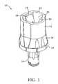
- FIG. 7is a perspective view of another embodiment of the attachment device.
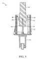
- FIG. 8is a cross-sectional view of the attachment device of FIG. 7 ;
- FIG. 9is a cross-sectional view of the attachment device of FIG. 7 and an administration port;
- FIG. 10is a side view of another embodiment of the attachment device.
- FIG. 11is perspective view of the slip ring of FIG. 10 ;
- FIG. 12is cross-sectional view of the another embodiment of the attachment device.
- the disclosed embodimentsaddress problems related to the proprietary nature of current attachment devices and the concerns these cause in time critical situations.
- the disclosed embodimentssolve these problems, at least in part, by providing an attachment arrangement for attaching a connector to an administration port of a fluid container.
- the attachment arrangementcomprises a housing having a receiving chamber configured to receive the administration port.
- the receiving chamberincludes a wall.
- the attachment arrangementalso includes at least one compliant retainer in the housing.
- the retaineris configured to comply with the administration port when the administration port is inserted into the housing.
- the compliant retaineralso secures the administration port within the housing.
- the attachment arrangementis configured to accommodate various sizes of administration ports.
- the attachment arrangementfurther includes a needle, which is at least partially within the housing. The needle is configured to pierce the administration port upon insertion of the administration port into the housing.
- an attachment arrangementcomprising a housing having a receiving chamber.
- the receiving chamberis configured to receive the administration port.
- the housingalso includes a compressible outer housing surface, which is configured to be compressed inwardly towards the center of the receiving chamber.
- the compressible outer housing surfacealso secures the administration port in the receiving chamber.
- the attachment arrangementalso includes a housing compression element mounted on the outer housing surface.
- the housing compression elementis configured to interact with the outer housing surface to compress the housing inwardly toward the center of the receiving chamber.
- the attachment arrangementis configured to accommodate various sizes of administration ports.
- the attachment arrangementfurther includes a needle at least partially within the housing. The needle is configured to pierce the administration port upon insertion of the administration port into the housing.
- FIGS. 1 and 2show an attachment arrangement 10 comprising a housing 12 .
- the attachment arrangement 10is especially suitable for permanently attaching a connector 14 , such as a needlefree connector 14 , to an administration port 16 of a fluid container, such as an intravenous (IV) bag (not shown).
- the housing 12is generally cylindrically shaped in the illustrated embodiment, though this is exemplary only, as a number of flat wall sections 18 may be provided in addition to curved sections 20 .
- the housing 12includes a receiving chamber 22 with an insertion opening 24 at one end of the housing 12 .
- An administration port 16(not shown in FIGS. 1 and 2 ) is inserted through the insertion opening 24 during use.
- a plurality of compliant retainers 26are located within the housing 12 .
- the compliant retainers 26may be configured as fingers, such as in the exemplary embodiment of FIGS. 1-6 , although other configurations may be employed.
- the compliant retainers 26are configured and positioned within the housing 12 such that when an administration port 16 is inserted into the housing 12 (as seen in FIG. 3 ), the compliant retainers 26 will secure the administration port 16 within the housing 12 .
- the housing 12may be formed from a polymeric material, or any other material.
- the compliant retainers 26may be formed from metal; however, any other materials, including a polymeric material, may also be used.
- the compliant retainers 26may be formed such that they extend along the length of the housing 12 towards the insertion opening 24 , then project inwardly from the wall 18 of receiving chamber 22 at a non-perpendicular angle and away from the insertion opening 24 . Viewed in FIGS. 1 and 2 , the compliant retainers 26 angle downwards and inwards from the top of the housing 12 . Referring now also to FIG. 5 , the compliant retainers 26 include a first portion 28 that extends along the length of the wall 18 , and a second portion 30 that is biased to project inwardly from the receiving chamber wall 18 . This second portion 30 is configured to flex towards the receiving chamber wall 18 during insertion of the administration port 16 .
- administration ports 16 of various sizescan be accommodated by the compliant retainers 26 .
- Smaller diameter administration ports 16will not flex the second portions 30 towards the receiving chamber walls 18 as much as larger diameter administration ports 16 .
- the compliant nature of the second portions 30allows different sized administration ports 16 to be easily inserted into the housing 12 .
- the attachment arrangement 10is able to accommodate administration ports 16 of different manufacturers and makes.
- the compliant retainers 26are compliant to allow the second portions 30 to flex towards the chamber walls 18 , the compliant retainers 26 are generally inflexible in the direction towards the insertion opening 24 .
- the compliant retainers 26will exert a spring-load force on the administration port 16 .
- the compliant retainers 26may flex back to their original position, or as close to their original position as the administration port 16 size will allow, to secure the administration port 16 within the housing 12 .
- the compliant retainers 26may catch a flange 32 ( FIG. 3 ) of the administration port 16 at a second end 29 ( FIG. 5 ) of the compliant retainers 26 .
- the administration port 16may not be easily removed from the housing 12 .
- a plurality of compliant retainers 26is preferred, as a plurality of compliant retainers 26 will also aid in the alignment of the administration port 16 within the housing 12 .
- a single compliant retainer 26may secure the administration port 16 within the housing 12 .
- the compliant retainers 26may completely prevent removal of the administration port 16 from the arrangement. Thus, the compliant retainers 26 would permanently secure the administration port 16 within the housing 12 .
- the attachment device 10further comprises a needle 34 that is configured to pierce the administration port 16 during insertion of the administration port 16 into the receiving chamber 22 .
- FIG. 2shows the needle 34 is located within the housing 12 .
- the needle 34may be formed of metal material, or any other material.
- the attachment device 10may be used in conjunction with a needlefree connector 14 ( FIGS. 1 and 2 ) that can be secured to the attachment arrangement 10 .
- the needlefree connector 14may be a closed male luer, such as a TexiumTM valve; a needleless female valve, such as a SmartSite® valve; an open male luer; an open female luer; or a drip chamber and IV set directly connected to the attachment arrangement 10 .
- the housing 12may include two portions, an upper portion 36 and a lower portion 38 .
- the upper portion 36includes a bottom ridge 40 .
- the lower portion 38 of the housing 12can then be connected to the bottom ridge 40 , thereby connecting the lower portion 38 of the housing 12 to the upper portion 36 of the housing 12 .
- the lower portion 38may be connected to the bottom ridge 40 of the upper portion 36 by a snap feature, screw threads, adhesive bonding, welding, fasteners, or any other means of attachment.
- the lower portion 38 of the housing 12may permanently attach to the upper portion 36 of the housing 12 . While manufacturing of the attachment device 10 is made easier by forming the housing 12 from at least two portions, it is contemplated that the housing 12 may include only one portion.
- FIG. 5shows that the compliant retainers 26 may include a connecting portion 42 at a first end 31 of the compliant retainers 26 .
- the connecting portion 42may be configured so that it can connect to the bottom ridge 40 of the upper portion 36 of the housing 12 .
- the connecting portion 42is generally hook-shaped.
- the connecting portion 42may connect to the bottom ridge 40 by wrapping under and around the bottom ridge 40 .
- the lower portion 38 of the housing 12is connected to the bottom ridge 40 of the housing 12 , the lower portion 38 will secure the compliant retainers 26 to the housing 12 by enclosing the connecting portion 42 around the bottom ridge 40 .
- the connecting portion 42 of the compliant retainers 26would also be permanently attached to the bottom ridge 40 of the upper portion 36 of the housing 12 .
- a fluid-tight seal 44may be formed between the attachment device 10 and the administration port 16 .
- the fluid-tight seal 44prevents fluid from escaping as fluid travels through the administration port 16 and the attachment arrangement 10 . Thus, patients will receive the correct dosage of fluid.
- the fluid-tight seal 44also serves to protect caregivers from unintended exposure to the drugs.
- FIG. 7shows another embodiment of the attachment arrangement 10 , in which the housing 12 includes a compressible outer housing surface 46 .
- the compressible outer housing surface 46is configured to be compressed inwardly, towards the center of the receiving chamber 22 .
- the compression of the outer housing surface 46allows the housing 12 to essentially enclose around and secure the administration port 16 in the receiving chamber 22 .
- the housing 12is flexible, and works to accommodate various sizes of administration ports 16 within the receiving chamber 22 .
- the attachment arrangement 10further includes a housing compression element 48 mounted on the outer housing surface 46 .
- the housing compression element 48is configured to interact with the outer housing surface 46 to compress the housing 12 inwardly toward the center of the receiving chamber 22 .
- manipulation of the housing-compression element 48is what causes the outer housing surface 46 to compress and secure the administration port 16 .
- the housing 12is substantially cylindrical in shape. However, it is contemplated that the housing 12 may be shaped in a non-cylindrical geometry as well.
- the housing 12includes at least one axial slit 50 ; however, a plurality of axial slits 50 may be included.
- the axial slit 50extends along the length of the housing 12 , and it provides the housing 12 with flexibility.
- the axial slit 50allows the housing 12 to flex open in the outward direction. This enables the receiving chamber 22 to receive and accommodate a variety of different sized administration ports 16 , including larger sized ones. Of course, if a smaller administration port 16 is used, there may not be a need for the housing 12 to flex in the outward direction.
- the axial slit 50also allows the housing 12 to inwardly compress such that the housing 12 may bear on and secure the administration port 16 within the receiving chamber 22 . As discussed above, this is beneficial because it allows the housing 12 to secure administration ports 16 of various sizes, and from various manufacturers, within the receiving chamber 22 .
- the outer housing surface 46may be threaded with threads, and the housing compression element 48 may be a nut concentrically mounted on the threads. Thus, the nut 48 may be screwed around the outer housing surface 46 , compressing and tightening the housing 12 around the administration port 16 .
- the housing 12may also include a first end 52 with an insertion opening 24 through which the administration port 16 is inserted into the receiving chamber 22 . Opposite the first end 52 is a second end 54 of the housing 12 .
- the threadsmay have a pitch diameter 56 that increases towards the first end 52 . The increase in pitch diameter 56 allows for insertion of larger administration ports 16 into the receiving chamber 22 .
- the presence of the axial slit 50eliminates any looseness created by the larger diameter 56 around an inserted administration port 16 , as the axial slit 50 enables the housing 12 to compress around the administration port 16 within the receiving chamber 22 , as the nut 48 is moved towards the first end 52 . This secures the administration port 16 within the housing 12 .
- the housing 12further includes a notch 58 , which is located within the receiving chamber 22 .
- the notch 58is configured to interact with a flange 32 of the administration port 16 (not shown in FIG. 8 ).
- FIG. 9when the administration port 16 is inserted into the housing 12 , the notch 58 grasps the flange 32 , further securing the administration port 16 within the housing 12 .
- the flexibility provided by the axial slit 50 coupled with the larger diameter 56allows the housing 12 to flex open and outwardly in order to receive an administration port 16 .
- the housingmay flex back to substantially its original position, or as close thereto as the size of the administration port 16 will allow.
- the pitch diameter 56 of the threadsincreases on the outer housing surface 46 from the notch 58 to the first end 52 .
- the movement of the nut 48 towards the first end 52 of the housing 12compresses the housing 12 inwardly. This secures the administration port 16 within the notch 58 of the housing 12 .
- the outer housing surface 46may also include a flange 60 remote from the first end 52 .
- the flange 60is configured and located such that a user may grasp onto it during rotation of the nut 48 around the housing 12 . This ensures easy and efficient use of the attachment arrangement 10 .
- the housing 12may not be threaded.
- the housing compression element 48is a slip ring 48 concentrically mounted on the outer housing surface 46 .
- the outer housing surface 46includes a plurality of notches 62 between the first and second ends 52 , 54 .
- the notches 62are configured such that movement of the slip ring 48 towards the first end 52 of the housing 12 when the administration port 16 is within the receiving chamber 22 compresses the housing 12 inwardly.
- the slip ring 48would fit into a different notch 48 .
- the slip ring 48may include an opening 64 .
- the openingis formed such that it may slide over the flange 60 .
- the flangemay include four separate segments.
- the opening 64may be shaped to include four corresponding cut-outs. The cut-outs may be aligned with the four segments such that the slip ring 48 may be slipped over the housing 12 .
- the slip ring 48further includes radially spaced slits 66 surround the opening. The slits 66 allow the slip ring 48 to have more flexibility when sliding over the housing 12 .
- the housing 12may be formed such that it may accommodate a variety of lengths of administration ports 16 . At least two undercuts 68 may be located inside the housing 12 to accommodate for the variously sized administration ports 16 .
Landscapes
- Health & Medical Sciences (AREA)
- Life Sciences & Earth Sciences (AREA)
- Animal Behavior & Ethology (AREA)
- General Health & Medical Sciences (AREA)
- Public Health (AREA)
- Veterinary Medicine (AREA)
- Pharmacology & Pharmacy (AREA)
- Fluid Mechanics (AREA)
- Physics & Mathematics (AREA)
- Vascular Medicine (AREA)
- Engineering & Computer Science (AREA)
- Anesthesiology (AREA)
- Biomedical Technology (AREA)
- Heart & Thoracic Surgery (AREA)
- Hematology (AREA)
- Infusion, Injection, And Reservoir Apparatuses (AREA)
Abstract
Description
Claims (14)
Priority Applications (16)
| Application Number | Priority Date | Filing Date | Title |
|---|---|---|---|
| US11/804,660US8597237B2 (en) | 2007-05-18 | 2007-05-18 | Universal needlefree bag access device |
| ES18202264TES2904903T3 (en) | 2007-05-18 | 2008-05-16 | Universal needleless bag access device |
| PCT/US2008/063917WO2008150671A2 (en) | 2007-05-18 | 2008-05-16 | Universal needlefree bag access device |
| BRPI0811604-0ABRPI0811604B1 (en) | 2007-05-18 | 2008-05-16 | ATTACHMENT ARRANGEMENT FOR ATTACHING A CONNECTOR TO AN ADMINISTRATION PORT OF A FLUID CONTAINER |
| ES08755719TES2709209T3 (en) | 2007-05-18 | 2008-05-16 | Universal bag access device without needle |
| AU2008260307AAU2008260307B2 (en) | 2007-05-18 | 2008-05-16 | Universal needlefree bag access device |
| EP08755719.5AEP2152221B1 (en) | 2007-05-18 | 2008-05-16 | Universal needlefree bag access device |
| EP18202264.0AEP3482787B1 (en) | 2007-05-18 | 2008-05-16 | Universal needlefree bag access device |
| RU2009147041/15ARU2475226C2 (en) | 2007-05-18 | 2008-05-16 | Universal fixation device |
| CA2687663ACA2687663C (en) | 2007-05-18 | 2008-05-16 | Universal needlefree bag access device |
| BR122019002740-4ABR122019002740B1 (en) | 2007-05-18 | 2008-05-16 | ATTACHMENT ARRANGEMENT FOR ATTACHING A CONNECTOR TO AN ADMINISTRATION PORT OF A FLUID CONTAINER |
| CN200880016549ACN101754743A (en) | 2007-05-18 | 2008-05-16 | Universal needlefree bag access device |
| JP2010508607AJP5591690B2 (en) | 2007-05-18 | 2008-05-16 | General-purpose needle-free bag / access device |
| ZA200908401AZA200908401B (en) | 2007-05-18 | 2009-11-26 | Universal needlefree bag access device |
| US14/094,437US9072829B2 (en) | 2007-05-18 | 2013-12-02 | Universal needlefree bag access device |
| US14/720,550US9814652B2 (en) | 2007-05-18 | 2015-05-22 | Universal needlefree bag access device |
Applications Claiming Priority (1)
| Application Number | Priority Date | Filing Date | Title |
|---|---|---|---|
| US11/804,660US8597237B2 (en) | 2007-05-18 | 2007-05-18 | Universal needlefree bag access device |
Related Child Applications (1)
| Application Number | Title | Priority Date | Filing Date |
|---|---|---|---|
| US14/094,437ContinuationUS9072829B2 (en) | 2007-05-18 | 2013-12-02 | Universal needlefree bag access device |
Publications (2)
| Publication Number | Publication Date |
|---|---|
| US20080287867A1 US20080287867A1 (en) | 2008-11-20 |
| US8597237B2true US8597237B2 (en) | 2013-12-03 |
Family
ID=39615786
Family Applications (3)
| Application Number | Title | Priority Date | Filing Date |
|---|---|---|---|
| US11/804,660Active2028-10-13US8597237B2 (en) | 2007-05-18 | 2007-05-18 | Universal needlefree bag access device |
| US14/094,437ActiveUS9072829B2 (en) | 2007-05-18 | 2013-12-02 | Universal needlefree bag access device |
| US14/720,550Active2027-08-07US9814652B2 (en) | 2007-05-18 | 2015-05-22 | Universal needlefree bag access device |
Family Applications After (2)
| Application Number | Title | Priority Date | Filing Date |
|---|---|---|---|
| US14/094,437ActiveUS9072829B2 (en) | 2007-05-18 | 2013-12-02 | Universal needlefree bag access device |
| US14/720,550Active2027-08-07US9814652B2 (en) | 2007-05-18 | 2015-05-22 | Universal needlefree bag access device |
Country Status (11)
| Country | Link |
|---|---|
| US (3) | US8597237B2 (en) |
| EP (2) | EP2152221B1 (en) |
| JP (1) | JP5591690B2 (en) |
| CN (1) | CN101754743A (en) |
| AU (1) | AU2008260307B2 (en) |
| BR (2) | BR122019002740B1 (en) |
| CA (1) | CA2687663C (en) |
| ES (2) | ES2709209T3 (en) |
| RU (1) | RU2475226C2 (en) |
| WO (1) | WO2008150671A2 (en) |
| ZA (1) | ZA200908401B (en) |
Cited By (4)
| Publication number | Priority date | Publication date | Assignee | Title |
|---|---|---|---|---|
| US9987479B2 (en) | 2015-07-09 | 2018-06-05 | Carefusion 303, Inc. | Closed male luer device for use with needleless access devices |
| US10039913B2 (en) | 2015-07-30 | 2018-08-07 | Carefusion 303, Inc. | Tamper-resistant cap |
| US10086187B2 (en) | 2012-02-07 | 2018-10-02 | Renishaw (Ireland) Limited | Drug delivery apparatus |
| US10195415B2 (en) | 2015-09-21 | 2019-02-05 | Carefusion 303, Inc. | Priming device |
Families Citing this family (15)
| Publication number | Priority date | Publication date | Assignee | Title |
|---|---|---|---|---|
| FR2958401A1 (en)* | 2010-04-01 | 2011-10-07 | Braun Medical Sas | DEVICE FOR COLLECTING A LIQUID SAMPLE FROM A FLEXIBLE POCKET |
| US8480560B2 (en)* | 2010-11-02 | 2013-07-09 | Ethicon Endo-Surgery, Inc. | Implantable medical port with fluid conduit retention sleeve |
| HUE028831T2 (en)* | 2010-12-16 | 2017-02-28 | Becton Dickinson France | Adapter and drug delivery device |
| EP2900145A1 (en)* | 2012-09-25 | 2015-08-05 | Boston Scientific Scimed, Inc. | Biopsy channel attachment adaptor |
| US9211231B2 (en)* | 2013-03-14 | 2015-12-15 | Carefusion 303, Inc. | Vial adapter for side engagement of vial cap |
| USD737960S1 (en)* | 2013-04-24 | 2015-09-01 | BIOMéRIEUX, INC. | Adapter cap with needle bore having flat internal surfaces |
| JP6412559B2 (en) | 2013-04-24 | 2018-10-24 | ビオメリュー・インコーポレイテッド | Adapter cap for sample collection container and associated core pin mold and associated method |
| EP3065694B1 (en)* | 2013-11-06 | 2020-04-29 | Becton Dickinson and Company Limited | System for closed transfer of fluids having connector |
| NZ631599A (en) | 2014-07-10 | 2018-08-31 | Abbvie Inc | Systems and methods for tubing delivery |
| KR101696741B1 (en)* | 2016-03-31 | 2017-01-16 | (주)메디라인액티브코리아 | Connecting structure for infusion supply tube of infusion supply set |
| RU2687181C1 (en)* | 2017-08-01 | 2019-05-07 | Общество С Ограниченной Ответственностью "Континенталь-Мед" | System for subcutaneous introduction of medicinal solutions, combined with paracorporal dispenser |
| IT201800002883A1 (en)* | 2018-02-20 | 2019-08-20 | Pierc Di Giovanelli Gabriele E C S A S | CONNECTOR FOR MEDICAL, DIAGNOSITIC AND PHYSOLOGICAL FLUID CONTAINERS |
| US20210069483A1 (en)* | 2019-09-10 | 2021-03-11 | Becton, Dickinson And Company | Vascular Access Device Adapter |
| IT202100006842A1 (en)* | 2021-03-22 | 2022-09-22 | Infusio S R L | CONNECTOR FOR MEDICAL, DIAGNOSTIC AND PHYSIOLOGICAL FLUID CONTAINERS |
| FR3159101A1 (en) | 2024-02-08 | 2025-08-15 | Cellquest | Connector and system for aseptic fluid connection |
Citations (13)
| Publication number | Priority date | Publication date | Assignee | Title |
|---|---|---|---|---|
| US4895570A (en) | 1987-06-05 | 1990-01-23 | Abbott Laboratories | Locking port shroud for peritoneal dialysis tubing connector |
| US5056756A (en) | 1991-04-24 | 1991-10-15 | U.S. Plastics Corporation | Fluid connector |
| US5201717A (en) | 1990-12-05 | 1993-04-13 | Philip Wyatt | Safety enclosure |
| WO1993016315A1 (en) | 1992-02-11 | 1993-08-19 | Huron Products Inc. | Connector for fluid filter |
| US5356396A (en) | 1992-09-29 | 1994-10-18 | Medical Associates Network Inc. | Infusion apparatus |
| WO1994023775A1 (en) | 1993-03-23 | 1994-10-27 | Abbott Laboratories | Securing collar for cannula connector |
| US5405340A (en)* | 1992-10-07 | 1995-04-11 | Abbott Laboratories | Threaded securing apparatus for flow connectors |
| US5514117A (en)* | 1988-09-06 | 1996-05-07 | Lynn; Lawrence A. | Connector having a medical cannula |
| EP0806597A1 (en) | 1996-05-10 | 1997-11-12 | Trinova GmbH | Quick acting coupling |
| US6142446A (en)* | 1995-05-16 | 2000-11-07 | Alaris Medical Systems, Inc. | Medical adapter having needleless valve and sharpened cannula |
| WO2006036192A1 (en) | 2004-09-27 | 2006-04-06 | Medtronic, Inc. | Catheter connection systems and methods |
| WO2006052655A2 (en) | 2004-11-05 | 2006-05-18 | Icu Medical, Inc. | Soft-grip medical connector |
| US20060149211A1 (en) | 2004-12-30 | 2006-07-06 | Vasogen Ireland Limited | Controlled flow apparatus for medical accessories |
Family Cites Families (7)
| Publication number | Priority date | Publication date | Assignee | Title |
|---|---|---|---|---|
| US4A (en)* | 1836-08-10 | Thomas Blanchard | Stock shaving or rounding machine for edges ends etc of ships' tackle-blocks | |
| US5A (en)* | 1836-08-10 | Thomas Blanchard | Machine for mortising solid wooden shells of ships' tackle-blocks | |
| US4998713A (en)* | 1990-01-10 | 1991-03-12 | Vaillancourt Vincent L | Needle connector |
| EP0453264A1 (en)* | 1990-04-17 | 1991-10-23 | Lynn, Lawrence A. | Medical connector |
| DE4313636C1 (en)* | 1993-04-26 | 1994-10-13 | Fresenius Ag | Connector system for the connection of liquid containers |
| US7025389B2 (en)* | 2003-06-06 | 2006-04-11 | Baxter International Inc. | Method and device for transferring fluid |
| WO2005030316A1 (en)* | 2003-09-26 | 2005-04-07 | Medtronic, Inc. | Sutureless pump connector |
- 2007
- 2007-05-18USUS11/804,660patent/US8597237B2/enactiveActive
- 2008
- 2008-05-16CACA2687663Apatent/CA2687663C/enactiveActive
- 2008-05-16ESES08755719Tpatent/ES2709209T3/enactiveActive
- 2008-05-16EPEP08755719.5Apatent/EP2152221B1/enactiveActive
- 2008-05-16AUAU2008260307Apatent/AU2008260307B2/enactiveActive
- 2008-05-16CNCN200880016549Apatent/CN101754743A/enactivePending
- 2008-05-16BRBR122019002740-4Apatent/BR122019002740B1/enactiveIP Right Grant
- 2008-05-16JPJP2010508607Apatent/JP5591690B2/enactiveActive
- 2008-05-16EPEP18202264.0Apatent/EP3482787B1/enactiveActive
- 2008-05-16ESES18202264Tpatent/ES2904903T3/enactiveActive
- 2008-05-16RURU2009147041/15Apatent/RU2475226C2/enactive
- 2008-05-16BRBRPI0811604-0Apatent/BRPI0811604B1/enactiveIP Right Grant
- 2008-05-16WOPCT/US2008/063917patent/WO2008150671A2/enactiveApplication Filing
- 2009
- 2009-11-26ZAZA200908401Apatent/ZA200908401B/enunknown
- 2013
- 2013-12-02USUS14/094,437patent/US9072829B2/enactiveActive
- 2015
- 2015-05-22USUS14/720,550patent/US9814652B2/enactiveActive
Patent Citations (13)
| Publication number | Priority date | Publication date | Assignee | Title |
|---|---|---|---|---|
| US4895570A (en) | 1987-06-05 | 1990-01-23 | Abbott Laboratories | Locking port shroud for peritoneal dialysis tubing connector |
| US5514117A (en)* | 1988-09-06 | 1996-05-07 | Lynn; Lawrence A. | Connector having a medical cannula |
| US5201717A (en) | 1990-12-05 | 1993-04-13 | Philip Wyatt | Safety enclosure |
| US5056756A (en) | 1991-04-24 | 1991-10-15 | U.S. Plastics Corporation | Fluid connector |
| WO1993016315A1 (en) | 1992-02-11 | 1993-08-19 | Huron Products Inc. | Connector for fluid filter |
| US5356396A (en) | 1992-09-29 | 1994-10-18 | Medical Associates Network Inc. | Infusion apparatus |
| US5405340A (en)* | 1992-10-07 | 1995-04-11 | Abbott Laboratories | Threaded securing apparatus for flow connectors |
| WO1994023775A1 (en) | 1993-03-23 | 1994-10-27 | Abbott Laboratories | Securing collar for cannula connector |
| US6142446A (en)* | 1995-05-16 | 2000-11-07 | Alaris Medical Systems, Inc. | Medical adapter having needleless valve and sharpened cannula |
| EP0806597A1 (en) | 1996-05-10 | 1997-11-12 | Trinova GmbH | Quick acting coupling |
| WO2006036192A1 (en) | 2004-09-27 | 2006-04-06 | Medtronic, Inc. | Catheter connection systems and methods |
| WO2006052655A2 (en) | 2004-11-05 | 2006-05-18 | Icu Medical, Inc. | Soft-grip medical connector |
| US20060149211A1 (en) | 2004-12-30 | 2006-07-06 | Vasogen Ireland Limited | Controlled flow apparatus for medical accessories |
Non-Patent Citations (4)
| Title |
|---|
| Communication Relating to the Results of the Partial International Search. |
| International Preliminary Report on Patentability mailed Nov. 3, 2009. |
| International Search Report from related PCT Application No. PCT/US2008/063917, dated Dec. 22, 2008. |
| Notification of Reasons for Rejection for Japanese Patent Application No. 2010-508607 dispatched Feb. 5, 2013. |
Cited By (10)
| Publication number | Priority date | Publication date | Assignee | Title |
|---|---|---|---|---|
| US10086187B2 (en) | 2012-02-07 | 2018-10-02 | Renishaw (Ireland) Limited | Drug delivery apparatus |
| US9987479B2 (en) | 2015-07-09 | 2018-06-05 | Carefusion 303, Inc. | Closed male luer device for use with needleless access devices |
| US11311709B2 (en) | 2015-07-09 | 2022-04-26 | Carefusion 303, Inc. | Closed male luer device for use with needleless access devices |
| US11975167B2 (en) | 2015-07-09 | 2024-05-07 | Carefusion 303, Inc. | Closed male luer device for use with needleless access devices |
| US10039913B2 (en) | 2015-07-30 | 2018-08-07 | Carefusion 303, Inc. | Tamper-resistant cap |
| US10773068B2 (en) | 2015-07-30 | 2020-09-15 | Carefusion 303, Inc. | Tamper-resistant cap |
| US11819652B2 (en) | 2015-07-30 | 2023-11-21 | Carefusion 303, Inc. | Tamper-resistant cap |
| US10195415B2 (en) | 2015-09-21 | 2019-02-05 | Carefusion 303, Inc. | Priming device |
| US11571558B2 (en) | 2015-09-21 | 2023-02-07 | Carefusion 303, Inc. | Priming device |
| US12171974B2 (en) | 2015-09-21 | 2024-12-24 | Carefusion 303, Inc. | Priming device |
Also Published As
| Publication number | Publication date |
|---|---|
| US20150250679A1 (en) | 2015-09-10 |
| RU2475226C2 (en) | 2013-02-20 |
| ZA200908401B (en) | 2010-08-25 |
| EP3482787B1 (en) | 2021-12-08 |
| EP2152221A2 (en) | 2010-02-17 |
| EP3482787A3 (en) | 2019-07-31 |
| JP2010527658A (en) | 2010-08-19 |
| RU2009147041A (en) | 2011-06-27 |
| AU2008260307B2 (en) | 2013-11-14 |
| BRPI0811604A2 (en) | 2014-11-04 |
| WO2008150671A2 (en) | 2008-12-11 |
| US20140088544A1 (en) | 2014-03-27 |
| JP5591690B2 (en) | 2014-09-17 |
| EP3482787A2 (en) | 2019-05-15 |
| WO2008150671A3 (en) | 2009-02-12 |
| AU2008260307A1 (en) | 2008-12-11 |
| ES2904903T3 (en) | 2022-04-06 |
| US9072829B2 (en) | 2015-07-07 |
| CA2687663C (en) | 2016-08-16 |
| BR122019002740B1 (en) | 2024-01-30 |
| US20080287867A1 (en) | 2008-11-20 |
| US9814652B2 (en) | 2017-11-14 |
| ES2709209T3 (en) | 2019-04-15 |
| BRPI0811604B1 (en) | 2024-01-23 |
| CA2687663A1 (en) | 2008-12-11 |
| EP2152221B1 (en) | 2018-10-31 |
| CN101754743A (en) | 2010-06-23 |
Similar Documents
| Publication | Publication Date | Title |
|---|---|---|
| US8597237B2 (en) | Universal needlefree bag access device | |
| US12383466B2 (en) | Fluid transfer device and packaging therefor | |
| US5437650A (en) | Securing collar for cannula connector | |
| US6253804B1 (en) | Needle safe transfer guard | |
| US10207099B1 (en) | Closure assembly for medical fitting | |
| US20080140055A1 (en) | Lockable enteral feeding adapter | |
| US20080140020A1 (en) | Lockable enteral feeding adapter | |
| US20150265500A1 (en) | Vial adapters | |
| EP2251061A2 (en) | Discriminating fluid connection system | |
| CA2158744C (en) | Securing collar for cannula connector |
Legal Events
| Date | Code | Title | Description |
|---|---|---|---|
| AS | Assignment | Owner name:CARDINAL HEALTH 303, INC., CALIFORNIA Free format text:ASSIGNMENT OF ASSIGNORS INTEREST;ASSIGNORS:YOW, D. GREGORY;PHILLIPS, JOHN C.;REEL/FRAME:019391/0811 Effective date:20070518 | |
| AS | Assignment | Owner name:CAREFUSION 303, INC.,CALIFORNIA Free format text:CHANGE OF NAME;ASSIGNOR:CARDINAL HEALTH 303, INC.;REEL/FRAME:023730/0406 Effective date:20090729 Owner name:CAREFUSION 303, INC., CALIFORNIA Free format text:CHANGE OF NAME;ASSIGNOR:CARDINAL HEALTH 303, INC.;REEL/FRAME:023730/0406 Effective date:20090729 | |
| AS | Assignment | Owner name:CAREFUSION 303, INC.,CALIFORNIA Free format text:CHANGE OF NAME;ASSIGNOR:CARDINAL HEALTH 303, INC.;REEL/FRAME:023800/0598 Effective date:20090801 Owner name:CAREFUSION 303, INC., CALIFORNIA Free format text:CHANGE OF NAME;ASSIGNOR:CARDINAL HEALTH 303, INC.;REEL/FRAME:023800/0598 Effective date:20090801 | |
| STCF | Information on status: patent grant | Free format text:PATENTED CASE | |
| FPAY | Fee payment | Year of fee payment:4 | |
| MAFP | Maintenance fee payment | Free format text:PAYMENT OF MAINTENANCE FEE, 8TH YEAR, LARGE ENTITY (ORIGINAL EVENT CODE: M1552); ENTITY STATUS OF PATENT OWNER: LARGE ENTITY Year of fee payment:8 | |
| MAFP | Maintenance fee payment | Free format text:PAYMENT OF MAINTENANCE FEE, 12TH YEAR, LARGE ENTITY (ORIGINAL EVENT CODE: M1553); ENTITY STATUS OF PATENT OWNER: LARGE ENTITY Year of fee payment:12 |