US8597206B2 - Biopsy probe assembly having a mechanism to prevent misalignment of components prior to installation - Google Patents
Biopsy probe assembly having a mechanism to prevent misalignment of components prior to installationDownload PDFInfo
- Publication number
- US8597206B2 US8597206B2US12/577,300US57730009AUS8597206B2US 8597206 B2US8597206 B2US 8597206B2US 57730009 AUS57730009 AUS 57730009AUS 8597206 B2US8597206 B2US 8597206B2
- Authority
- US
- United States
- Prior art keywords
- driver
- alignment feature
- assembly
- biopsy probe
- slider
- Prior art date
- Legal status (The legal status is an assumption and is not a legal conclusion. Google has not performed a legal analysis and makes no representation as to the accuracy of the status listed.)
- Active, expires
Links
Images


Classifications
- A—HUMAN NECESSITIES
- A61—MEDICAL OR VETERINARY SCIENCE; HYGIENE
- A61B—DIAGNOSIS; SURGERY; IDENTIFICATION
- A61B10/00—Instruments for taking body samples for diagnostic purposes; Other methods or instruments for diagnosis, e.g. for vaccination diagnosis, sex determination or ovulation-period determination; Throat striking implements
- A61B10/02—Instruments for taking cell samples or for biopsy
- A61B10/0233—Pointed or sharp biopsy instruments
- A61B10/0266—Pointed or sharp biopsy instruments means for severing sample
- A61B10/0275—Pointed or sharp biopsy instruments means for severing sample with sample notch, e.g. on the side of inner stylet
- A—HUMAN NECESSITIES
- A61—MEDICAL OR VETERINARY SCIENCE; HYGIENE
- A61B—DIAGNOSIS; SURGERY; IDENTIFICATION
- A61B10/00—Instruments for taking body samples for diagnostic purposes; Other methods or instruments for diagnosis, e.g. for vaccination diagnosis, sex determination or ovulation-period determination; Throat striking implements
- A61B10/02—Instruments for taking cell samples or for biopsy
- A61B10/0233—Pointed or sharp biopsy instruments
- A61B10/0283—Pointed or sharp biopsy instruments with vacuum aspiration, e.g. caused by retractable plunger or by connected syringe
- A—HUMAN NECESSITIES
- A61—MEDICAL OR VETERINARY SCIENCE; HYGIENE
- A61B—DIAGNOSIS; SURGERY; IDENTIFICATION
- A61B10/00—Instruments for taking body samples for diagnostic purposes; Other methods or instruments for diagnosis, e.g. for vaccination diagnosis, sex determination or ovulation-period determination; Throat striking implements
- A61B10/02—Instruments for taking cell samples or for biopsy
- A61B2010/0208—Biopsy devices with actuators, e.g. with triggered spring mechanisms
- A—HUMAN NECESSITIES
- A61—MEDICAL OR VETERINARY SCIENCE; HYGIENE
- A61B—DIAGNOSIS; SURGERY; IDENTIFICATION
- A61B17/00—Surgical instruments, devices or methods
- A61B2017/00681—Aspects not otherwise provided for
- A61B2017/00734—Aspects not otherwise provided for battery operated
Definitions
- the present inventionrelates to a biopsy apparatus, and, more particularly, to a biopsy probe assembly having a mechanism to prevent misalignment of components of the biopsy probe assembly prior to installation, so as to aid in the proper mounting of the biopsy probe assembly to the driver assembly of a biopsy apparatus.
- a biopsymay be performed on a patient to help in determining whether the cells in a biopsied region are cancerous.
- One type of vacuum assisted biopsy apparatusincludes a hand-held driver assembly having a vacuum source, and a disposable biopsy probe assembly configured for releasable attachment to the driver assembly.
- One biopsy technique used to evaluate breast tissueinvolves inserting a biopsy probe into the breast tissue region of interest to capture one or more tissue samples from the region.
- the biopsy probetypically includes a biopsy cannula, e.g., a needle, having a cylindrical side wall defining a lumen, and having a side sample notch located near the distal end that extends though the side wall to the lumen.
- a cutting cannulais positioned coaxial with the biopsy cannula to selectively open and close the sample notch. Vacuum is applied to the lumen, and in turn to the sample notch, for receiving the tissue to be sampled when the sample notch is opened, after which the sample notch is closed by the cutting cannula to sever the tissue, and the severed tissue is transported by vacuum out of the lumen and collected.
- the biopsy probeTo insure proper operation of the biopsy apparatus, the biopsy probe must be properly mounted to the driver assembly, with the various mechanical drive components of the driver assembly being properly engaged with the various mechanical driven components of the biopsy probe.
- the present inventionprovides a biopsy probe assembly having a mechanism to prevent misalignment of components of the biopsy probe assembly prior to and during installation of the biopsy probe assembly on the driver assembly, so as to aid in the proper mounting of the biopsy probe assembly to the driver assembly of a biopsy apparatus.
- first and secondpreceding an element name, e.g., first alignment feature, second alignment feature, third alignment feature, etc., are for identification purposes to distinguish between different elements having similar characteristic, and are not intended to necessarily imply order, unless otherwise specified, nor are the terms “first”, “second”, etc., intended to preclude the inclusion of additional similar elements.
- the inventionin one form thereof, is directed to a biopsy probe assembly configured for installation on a driver assembly.
- the biopsy probe assemblyincludes a housing, and a biopsy probe having a cannula arranged along a longitudinal axis.
- a sample basketis arranged coaxially with the cannula.
- a cannula driveris coupled to the housing.
- the cannula driveris connected to the cannula to facilitate movement of the cannula along the longitudinal axis.
- a driven unitis contained at least in part in the housing. The driven unit is coupled to the sample basket to facilitate movement of the sample basket relative to the longitudinal axis.
- a slider assemblyhas a slider driver and a slider that are movable to selectively couple the cannula driver to the driven unit in a piercing shot mode and to decouple the cannula driver from the driven unit in a tissue harvesting mode.
- a coveris movably coupled to the housing.
- a plurality of alignment featuresis provided, each alignment feature being associated with a respective one of the cannula driver, the slider assembly and the cover. The plurality of alignment features when aligned form a continuous passage.
- a safety alignment pinis positioned in the continuous passage to engage each of the plurality of alignment features to prevent relative movement of the cannula driver, the slider driver and the cover prior to installation of the biopsy probe assembly on the driver assembly.
- the inventionin another form thereof, is directed to a biopsy probe assembly configured for installation on a driver assembly.
- the biopsy probe assemblyincludes a biopsy probe having a cannula arranged along a longitudinal axis.
- a coverhas a first alignment feature.
- a housingis slidably coupled to the cover.
- the housinghas a second alignment feature.
- a first driven unitis slidably coupled to the housing.
- the first driven unithas a third alignment feature.
- the first driven unitis connected to the cannula to facilitate movement of the cannula along the longitudinal axis.
- An alignment pinis configured to facilitate concurrent engagement with each of the first alignment feature, the second alignment feature, and the third alignment feature so as to lock relative positions of the cover, the housing, and the first driven unit.
- the inventionin another form thereof, is directed to a biopsy probe assembly configured for installation on a driver assembly.
- the biopsy probe assemblyincludes a biopsy probe having a sample basket arranged coaxially with a cutter cannula along a longitudinal axis.
- a coverhas a first alignment feature.
- a housingis slidably coupled to the cover.
- the housinghas a second alignment feature.
- a cannula driverhas a third alignment feature.
- the cannula driveris slidably coupled to the housing.
- the cannula driveris connected to the cutter cannula to facilitate movement of the cutter cannula along the longitudinal axis.
- a flexible toothed rackis connected to the sample basket to facilitate movement of the sample basket along the longitudinal axis.
- a gear trainis contained in the housing.
- the gear trainincludes a clutch drive configured to selectively drivably couple the gear train to the flexible toothed rack.
- a pivot memberis pivotably coupled to the cannula driver. The pivot member provides selectable coupling between the cannula driver and the flexible toothed rack.
- a slider assemblyis coupled to the pivot member to operate the pivot member to facilitate the selectable coupling between the cannula driver and the flexible toothed rack via the pivot member.
- the slider assemblyis further configured to selectively engage the clutch drive.
- the slider assemblyincludes a slider driver movable between an extended position and a retracted position. The retracted position of the slider driver effects an engagement of the clutch drive and disengagement between the cannula driver and the flexible toothed drive.
- the extended position of the slider drivereffects a disengagement of the clutch drive and an engagement between the cannula driver and the flexible toothed drive.
- the slider driverhas a fourth alignment feature.
- An alignment pinis configured to facilitate manual concurrent engagement with each of the first alignment feature, the second alignment feature, the third alignment feature and the fourth alignment feature so as to lock relative positions of the cover, the housing, the cannula driver and the slider driver.
- the inventionin another form thereof, is directed to a biopsy apparatus including a driver assembly and a biopsy probe assembly.
- the driver assemblyhas a first drive and a controller communicatively coupled to the first drive.
- the controllerexecutes program instructions to preposition the first drive to an initialized state.
- a biopsy probe assemblyis configured for releasable attachment to the driver assembly after the driver assembly is placed in the initialized state.
- the biopsy probe assemblyincludes a biopsy probe having a cannula arranged along a longitudinal axis.
- a coverhas a first alignment feature.
- a housingis slidably coupled to the cover.
- the housinghas a second alignment feature.
- a first driven unitis movably coupled to the housing. The first driven unit is configured for drivable coupling to the first drive of the driver assembly.
- the first driven unithas a third alignment feature.
- the first driven unitis connected to the cannula to facilitate movement of the cannula along the longitudinal axis.
- An alignment pinis configured to facilitate concurrent engagement with each of the first alignment feature, the second alignment feature and the third alignment feature so as to lock relative positions of the cover, the housing and the first driven unit.
- the inventionin another form thereof, is directed to a biopsy probe assembly configured for installation on a driver assembly.
- the biopsy probe assemblyincludes a plurality of components, each of the plurality of components being movable relative to another of the plurality of components, and each of the plurality of movable components having a respective alignment feature, wherein collectively the biopsy probe assembly has a plurality of alignment features.
- the plurality of alignment features of the plurality of componentsis aligned to form a continuous passage.
- a safety alignment pinis inserted into the continuous passage so as to lock relative positions of the plurality of components.
- the inventionin another form thereof, is directed to a method for installing a biopsy probe assembly on a driver assembly to form a biopsy apparatus.
- the methodincludes prepositioning a drive of the driver assembly to an initialized state; providing the biopsy probe assembly configured for installation on the driver assembly, the biopsy probe assembly including a biopsy probe having a cannula arranged along a longitudinal axis coaxially with a sample basket, a cover having a first alignment feature, a housing slidably coupled to the cover, the housing having a second alignment feature, and a driven unit slidably coupled to the housing, the driven unit having a third alignment feature, the driven unit being connected to the cannula to facilitate movement of the cannula along the longitudinal axis, wherein the first alignment feature, the second alignment feature and the third alignment feature are aligned to form a continuous passage, with an alignment pin being received in the continuous passage to lock relative positions of the cover, the housing and the driven unit; seating at least a portion of the biopsy probe assembly in an elongate cavity of the
- FIG. 1is a perspective view of a biopsy apparatus, configured in accordance with an embodiment of the present invention, with a disposable biopsy probe mounted to a driver assembly;
- FIG. 2is a perspective view of a biopsy apparatus of FIG. 1 , with the disposable biopsy probe detached from the driver assembly;
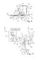
- FIG. 3is a schematic representation of the biopsy apparatus of FIG. 1 ;
- FIG. 4Ais a perspective view of a vacuum seal element of the vacuum path of the driver assembly of FIG. 3 ;
- FIG. 4Bis a perspective view of a vacuum seal element of the vacuum path of the disposable biopsy probe of FIG. 3 ;
- FIG. 5Ais a perspective view of the fluid management tank of the disposable biopsy probe shown in FIGS. 2 and 3 , with a portion broken away to expose a filter arrangement;
- FIG. 5Bis an exploded view of a plurality of fluid absorption layers of the filter arrangement of FIG. 5A ;
- FIG. 5Cis a perspective view of a porous filter element of the filter arrangement of FIG. 5A ;
- FIG. 6is a side view of the disposable biopsy probe of FIG. 2 showing in further detail a tissue sample retrieval mechanism with the sample collection tank removed;
- FIG. 7is a side view of the disposable biopsy probe of FIG. 6 showing the tissue sample retrieval mechanism with the sample collection tank installed, and with the sample collection tank in the raised position;
- FIG. 8is a side view of the disposable biopsy probe of FIG. 6 showing the tissue sample retrieval mechanism with the sample collection tank installed, and with the sample collection tank in the lowered collection position;
- FIG. 9is a side view of a portion of the tissue sample retrieval mechanism of FIG. 8 with a portion of the cutter cannula sectioned away to expose the retracting sample basket, and with a portion of the sample basket broken way to show the interaction of the tissue sample scoop of the sample collection tank with the sample notch;
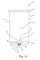
- FIG. 10is an enlarged front view of the sample collection tank of FIG. 9 showing the interaction of the rim of the sample collection tank with the sample basket shown in section along line 10 - 10 of FIG. 9 ;
- FIG. 11is a top view of the tank positioning mechanism of FIG. 8 ;
- FIG. 12is a top view of the sample basket and the lift member of the disposable biopsy probe of FIG. 7 , with a portion of lift member broken away to expose a T-shaped stop, and a leaf spring tongue forming a portion of the T-shaped stop for removing residual tissue material and debris from a vacuum path at the sample notch of the sample basket;
- FIG. 13is a side view of the disposable biopsy probe of FIG. 7 showing the latch member of the tank positioning mechanism in the latched transport position;
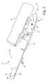
- FIG. 14is a side view of a portion of the biopsy probe assembly of FIG. 1 , opposite to the side view shown in FIG. 2 , and illustrating a slider assembly;
- FIG. 15Ashows the slider driver and slider of the slider assembly of FIG. 14 , with the slider in the raised position
- FIG. 15Bshows the slider driver and slider of the slider assembly of FIG. 14 , with the slider in the lowered position
- FIG. 16Ais a perspective view showing the flexible tooth rack and a pivot member that selectively engages the flexible toothed rack, with the pivot member disengaged from the flexible toothed rack;
- FIG. 16Bis a perspective view showing the flexible tooth rack and a pivot member that selectively engages the flexible toothed rack, with the pivot member engaged with the flexible toothed rack;
- FIG. 17Ais a perspective view of a clutch drive having an intermediate gear drivably engaged with a rack drive gear
- FIG. 17Bis a perspective view of a clutch drive having the intermediate gear disengaged from driving the rack drive gear;
- FIG. 18is a bottom perspective view of the driver assembly of FIG. 1 ;
- FIG. 19is a perspective view of a portion the biopsy probe assembly of FIG. 1 ;
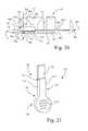
- FIG. 20is a side view of a portion of the biopsy probe assembly of FIG. 1 , opposite to the side view shown in FIG. 2 , and illustrating a slider assembly and the safety alignment pin installed;
- FIG. 21is an enlarged perspective view of the safety alignment pin shown in FIG. 20 ;
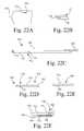
- FIG. 22Ais a bottom view of a portion of the cover of the biopsy probe assembly of FIG. 20 , which includes a cover alignment feature;
- FIG. 22Bis a top view of a portion of the housing of the biopsy probe assembly of FIG. 20 , which includes a housing alignment feature;
- FIG. 22Cis a top view of a portion of the first driven unit (cannula driver) of the biopsy probe assembly of FIG. 20 , which includes a cannula driver alignment feature;
- FIG. 22Dis a top view of the slider driver illustrated in FIG. 15A , which includes a slider driver alignment feature;
- FIG. 22Eis a top view of the slider illustrated in FIG. 15A ;
- FIG. 22Fis an opposite side view of the slider driver and slider illustrated in FIG. 15A .
- a biopsy apparatus 10which generally includes a non-invasive, e.g., non-disposable, driver assembly 12 and a disposable biopsy probe assembly 14 .
- driver assembly 12 and disposable biopsy probe assembly 14collectively include a fluid management system 16 that includes a vacuum source 18 , first vacuum path 20 and a second vacuum path 22 .
- Vacuum source 18 and a first vacuum path 20are permanently associated with driver assembly 12
- a second vacuum path 22is permanently associated with disposable biopsy probe assembly 14 , as more fully described below, to help facilitate the safe and effective collection of a biopsy tissue sample.
- non-disposableis used to refer to a device that is intended for use on multiple patients during the lifetime of the device
- the term “disposable”is used to refer to a device that is intended to be disposed of after use on a single patient.
- vacuum pathmeans a fluid passageway used to facilitate a vacuum between two points, the fluid passageway passing through one or more components, such as for example, one or more of tubing, conduits, couplers, and interposed devices.
- permanently associatedmeans a connection that is not intended for releasable attachment on a routine basis during the lifetime of the components.
- driver assembly 12 including vacuum source 18 and first vacuum path 20is reusable as a unit in its entirety
- disposable biopsy probe assembly 14 and second vacuum path 22are disposable as a unit in its entirety.
- Driver assembly 12includes a housing 24 configured, and ergonomically designed, to be grasped by a user.
- Driver assembly 12includes (contained within housing 24 ) vacuum source 18 , first vacuum path 20 , a controller 26 , an electromechanical power source 28 , and a vacuum monitoring mechanism 30 .
- a user interface 32is located to be mounted to, and externally accessible with respect to, housing 24 .
- Housing 24defines an elongate cavity 241 which is configured for receiving a corresponding housing 57 of biopsy probe assembly 14 when driver assembly 12 is mounted to biopsy probe assembly 14 .
- Controller 26is communicatively coupled to electromechanical power source 28 , vacuum source 18 , user interface 32 , and vacuum monitoring mechanism 30 .
- Controller 26may include, for example, a microprocessor and associated memory for executing program instructions to perform functions associated with the retrieval of biopsy tissue samples, such as controlling one or more components of vacuum source 18 and electromechanical power source 28 .
- Controller 26also may execute program instructions to monitor one or more conditions and/or positions of components of biopsy apparatus 10 , and to monitor the status of fluid management system 16 associated with driver assembly 12 and biopsy probe assembly 14 .
- the user interface 32includes control buttons 321 and visual indicators 322 , with control buttons 321 providing user control over various functions of biopsy apparatus 10 , and visual indicators 322 providing visual feedback of the status of one or more conditions and/or positions of components of biopsy apparatus 10 .
- the electromechanical power source 28may include, for example, an electrical energy source, e.g., battery, 34 and an electrical drive assembly 36 .
- Battery 34may be, for example, a rechargeable battery. Battery 34 provides electrical power to all electrically powered components in biopsy apparatus 10 , and thus for simplicity in the drawings, such electrical couplings are not shown.
- battery 34is electrically coupled to vacuum source 18 , controller 26 , user interface 32 and electrical drive assembly 36 .
- electrical drive assembly 36includes a first drive 361 and a second drive 362 , each being respectively coupled to battery 34 , and each of first drive 361 and second drive 362 respectively electrically and controllably coupled to user interface 32 .
- First drive 361may include an electrical motor 381 and a motion transfer unit 401 (shown schematically by a line).
- Second drive 362may include an electrical motor 382 and a motion transfer unit 402 (shown schematically by a line).
- Each electrical motor 381 , 382may be, for example, a direct current (DC) motor, stepper motor, etc.
- Motion transfer unit 401 of first drive 361may be configured, for example, with a rotational-to-linear motion converter, such as a worm gear arrangement, rack and pinion arrangement, etc., or a solenoid-slide arrangement, etc.
- Motion transfer unit 402 of second drive 362may be configured to transmit rotary motion.
- Each of first drive 361 and second drive 362may include one or more of a gear, gear train, belt/pulley arrangement, etc.
- Vacuum source 18is electrically coupled to battery 34 , and has a vacuum source port 181 for establishing a vacuum. Vacuum source 18 is electrically and controllably coupled to user interface 32 . Vacuum source 18 may further include, for example, a vacuum pump 182 driven by an electric motor 183 . Vacuum pump 182 may be, for example, a peristaltic pump, a diaphragm pump, syringe-type pump, etc.
- First vacuum path 20 of driver assembly 12is permanently associated with vacuum source 18 .
- First vacuum path 20also sometimes referred to as a non-disposable vacuum path, has a proximal end 201 and a distal end 202 , and includes, for example, conduits 203 , a first one-way valve 204 , and a particulate filter 205 .
- Proximal end 201is fixedly coupled to vacuum source 18 in fluid communication therewith, e.g., is fixedly connected to vacuum source port 181 of vacuum source 18 .
- distal end 202includes a first vacuum seal element 206 .
- first vacuum seal element 206is a planar abutment surface that surrounds a first passageway 207 of first vacuum path 20 .
- First one-way valve 204is configured and arranged to permit a negative pressure fluid flow toward vacuum source 18 and to prevent a positive pressure fluid flow away from vacuum source 18 toward the distal end 202 of first vacuum path 20 .
- the first one-way valve 204may be, for example, a check-valve, such as a ball valve or reed valve, that opens with a fluid flow toward vacuum source 18 , and closes in the case of a reverse (positive) flow away from vacuum source 18 .
- particulate filter 205is located between vacuum source 18 and distal end 202 of first vacuum path 20 .
- Particulate filter 205may be, for example, a mesh screen formed from metal or plastic. However, it is contemplated that particulate filter 205 may be located in fluid management system 16 between vacuum source 18 and a vacuum receiving component of biopsy probe assembly 14 .
- the vacuum monitoring mechanism 30is coupled to vacuum source 18 to shut off vacuum source 18 when a sensed vacuum level has fallen below a threshold level.
- Vacuum monitoring mechanism 30may include, for example, a vacuum monitor and control program executing on controller 26 , and a pressure sensor 301 coupled to controller 26 , and in fluid communication with first vacuum path 20 for detecting a pressure in first vacuum path 20 . If, for example, the vacuum flow level in first vacuum path 20 falls below a predetermined level, indicating a restriction in fluid management system 16 , controller 26 may respond by shutting off vacuum source 18 , e.g., turning off electric motor 183 .
- controller 26may monitor the current supplied to electric motor 183 , and if the current exceeds a predetermined amount, indicating a restriction in fluid management system 16 , controller 26 may respond by shutting off vacuum source 18 , e.g., turning off electric motor 183 .
- the disposable biopsy probe assembly 14is configured for releasable attachment to driver assembly 12 .
- releasable attachmentmeans a configuration that facilitates an intended temporary connection followed by selective detachment involving a manipulation of disposable biopsy probe assembly 14 relative to driver assembly 12 , without the need for tools.
- the disposable biopsy probe assembly 14includes a cover (frame) 141 to which a transmission device 42 , a biopsy probe 44 , housing 57 and the second vacuum path 22 are mounted, with housing 57 being slidably coupled to cover 141 .
- the sliding coupling of housing 57 to cover 141may be achieved, for example, by a rail and U-bracket configuration 14 - 1 , illustrated schematically in FIG. 14 .
- Cover 141serves as a slidable cover to close elongate cavity 241 in housing 24 of driver assembly 12 to protect the internal structure of driver assembly 12 when biopsy probe assembly 14 is mounted to driver assembly 12 .
- Biopsy probe 44is drivably coupled to transmission device 42
- transmission device 42is drivably coupled to electromechanical power source 28 of driver assembly 12 when biopsy probe assembly 14 is mounted to driver assembly 12 .
- transmission device 42includes a first driven unit 421 and a second driven unit 422 that are drivably engaged with various components of biopsy probe 44 .
- first driven unit 421is drivably engaged with first drive 361 of electrical drive assembly 36 of driver assembly 12 .
- Second driven unit 422is drivably engaged with second drive 362 of electrical drive assembly 36 of driver assembly 12 .
- First driven unit 421is slidably coupled to housing 57
- second driven unit 422is contained in housing 57 .
- the sliding coupling of first driven unit 421(e.g., a cannula driver) may be achieved by placing first driven unit 421 in a longitudinal slide channel 57 - 1 formed in housing 57 ( FIG. 16 ).
- biopsy probe 44includes a sample basket 441 and a cutter cannula 442 .
- Sample basket 441has a sharpened tip 443 to aid in puncturing tissue and has a sample notch 444 in the form of a recessed region for receiving a biopsy tissue sample.
- Sample basket 441 and a cutter cannula 442are configured to be individually movable along a longitudinal axis 445 .
- cutter cannula 442is linearly driven by first driven unit 421 to traverse over sample notch 444 of sample basket 441 along longitudinal axis 445 .
- first driven unit 421may be in the form of a linear slide that is drivably engaged with first drive 361 of driver assembly 12 , which in turn drives cutter cannula 442 along longitudinal axis 445 in a first direction 46 , i.e., toward a proximal end of driver assembly 12 , to expose sample notch 444 of sample basket 441 , and drives cutter cannula 442 in a second direction 48 opposite to first direction 46 to sever tissue prolapsed into sample notch 444 .
- first driven unit 421 and second driven unit 422may be configured to operate in unison to advance both sample basket 441 and cutter cannula 442 in unison along an longitudinal axis 445 in a piercing shot operation to aid in inserting biopsy probe 44 into fibrous tissue.
- the second driven unit 422may include a flexible toothed rack 50 and a gear train 52 .
- Flexible toothed rack 50is connected to sample basket 441 , and a portion of gear train 52 is engaged with the teeth of flexible toothed rack 50 .
- second drive 362transfers rotary motion to gear train 52 , and in turn gear train 52 engages flexible toothed rack 50 to move sample basket 441 linearly to transport the tissue captured in sample notch 444 out of the body of the patient.
- Flexible toothed rack 50is received in a coiling unit 54 when retracting, thereby enabling substantial reduction in the overall device length of biopsy apparatus 10 as compared to a rigid capture system.
- Each harvested tissue sampleis transported out of the body of the patient and is collected by tissue sample retrieval mechanism 56 , which scoops the tissue sample out of sample notch 444 .
- coiling unit 54 and tissue sample retrieval mechanism 56are as an integral unit with housing 57 that is common to coiling unit 54 and tissue sample retrieval mechanism 56 .
- Housing 57is attached, e.g., slidably coupled, to cover 141 , and contains gear train 52 with at least a portion of flexible toothed rack 50 in engagement with gear train 52 .
- Tissue sample retrieval mechanism 56will be described in greater detail later.
- housing 57has a distinct shape S 1 as a combination of curved and flat surfaces with an overall height H 1 , length L 1 , and width W 1 dimensions which in combination define a unique profile of housing 57 .
- the second vacuum path 22also sometimes referred to as a disposable vacuum path 22 , has a first end 221 and a second end 222 , and includes for example, conduits 223 , a second one-way valve 224 , and a fluid management tank 225 .
- the first end 221is configured for removable attachment to the distal end 202 of the first vacuum path 20 of driver assembly 12 .
- the second end 222is coupled in fluid communication with sample basket 441 , and more particularly, is coupled in fluid communication with sample notch 444 of sample basket 441 .
- the first end 221 of the disposable vacuum path 22includes a second vacuum seal element 226 .
- the first vacuum seal element 206 of the driver assembly 12contacts the second vacuum seal element 226 of the disposable biopsy probe assembly 14 in sealing engagement when the disposable biopsy probe assembly 14 is attached to driver assembly 12 .
- the second vacuum seal element 226is a compliant, e.g., rubber, annular member that surrounds a second passageway 227 of the second vacuum path 22 .
- the second one-way valve 224configured and arranged to permit the negative pressure fluid flow from sample basket 441 toward the first end 221 of the second vacuum path 22 , and to redundantly (in conjunction with first one-way valve 204 of driver assembly 12 ) prevent any positive pressure fluid flow in a direction from the first end 221 of the second vacuum path 22 toward sample basket 441 .
- the second one-way valve 224provides a redundant second level of protection in preventing any positive pressure from reaching sample notch 444 of sample basket 441 .
- the second one-way valve 224may be, for example, a duckbill valve, e.g., a reed-type valve, that opens with a fluid flow out the bill portion of the duckbill valve, and closes with a reverse flow. As shown, the second one-way valve 224 may be positioned within the second vacuum seal element 226 at first end 221 of second vacuum path 22 .
- fluid management tank 225is fluidically interposed in the second vacuum path 22 between the first end 221 and the second end 222 .
- Fluid management tank 225includes a body 58 and a filter arrangement 60 contained within body 58 configured to prevent a flow of residual biopsy biological material, e.g., blood and particulate matter, from sample notch 444 of sample basket 441 to vacuum source 18 of driver assembly 12 .
- Body 58 of fluid management tank 225has a first port 581 and a second port 582 , with the second vacuum path 22 continuing between the first port 581 and the second port 582 .
- the second port 582 of fluid management tank 225is coupled to sample basket 441 .
- Each of the second one-way valve 224 and the second vacuum seal element 226 of the second vacuum path 22is coupled to the first port 581 of fluid management tank 225 , and in the present embodiment, is mounted to an external surface of body 58 of fluid management tank 225 .
- filter arrangement 60includes a plurality of fluid absorption layers 62 , individually identified as layers 621 , 622 , 623 and 624 , arranged side by side, with each fluid absorption layer 621 , 622 , 623 and 624 being spaced apart from an adjacent fluid absorption layer e.g., 621 to 622 , 622 to 623 , 623 , to 624 .
- Each fluid absorption layer 621 , 622 , 623 and 624has a respective through opening 641 , 642 , 643 , 644 , wherein adjacent through openings of through openings 641 , 642 , 643 , 644 of the plurality of fluid absorption layers 62 are offset one to the next, e.g., in at least one of an X, Y, and Z direction, to form a tortuous open fluid passageway 66 through the plurality of fluid absorption layers 62 .
- Each fluid absorption layer 621 , 622 , 623 and 624may be, for example, a blotting paper.
- filter arrangement 60may further include a porous filter element 68 arranged to be fluidically in series with the plurality of fluid absorption layers 62 along the second vacuum path 22 that defines second passageway 227 .
- the porous filter element 68exhibits increased restriction to fluid flow as an increased number of pores 70 in the porous filter element 68 become clogged by residual biopsy biological material, such as blood and tissue particles.
- tissue sample retrieval mechanism 56collects tissue samples that have been harvested by scooping the tissue sample out of sample notch 444 of sample basket 441 of biopsy probe 44 .
- biopsy probe 44 of biopsy probe assembly 14includes a biopsy cannula, e.g., cutter cannula 442 , and sample basket 441 arranged coaxially about longitudinal axis 445 .
- Sample basket 441 having sample notch 444is movably disposed relative to biopsy (cutter) cannula 442 along longitudinal axis 445 from a tissue harvesting position 72 , as shown in FIGS. 6 and 7 , to a tissue sample retrieval region 74 , as illustrated in FIGS. 6-8 by electromechanical power source 28 and second drive 362 , as more fully described above with respect to FIG. 3 .
- sample notch 444is an elongate recessed region of sample basket 441 having a generally semicircular cross-section, and has a recessed floor 76 , a pair of spaced elongate edges 78 , 80 on opposite sides of recessed floor 76 , a leading transition bevel 82 , and a trailing transition bevel 84 .
- Leading transition bevel 82 and trailing transition bevel 84are located at opposite ends of the elongate recessed region, i.e., sample notch, 444 .
- tissue sample retrieval mechanism 56includes a sample tank receptacle 86 , a sample collection tank 88 , a toggle mechanism 90 , and a tank positioning mechanism 92 .
- Sample collection tank 88is configured for removable insertion into sample tank receptacle 86 .
- Sample tank receptacle 86which may be formed integral with housing 57 , includes a hollow guide 87 size to slidably receive sample collection tank 88 .
- the configuration of sample tank receptacle 86is such that sample tank receptacle 86 permits bi-directional movement of sample collection tank 88 in directions 89 (signified by double headed arrow) that are substantially perpendicular to longitudinal axis 445 .
- the configuration of sample tank receptacle 86is such that sample tank receptacle 86 prohibits movement of sample collection tank 88 in a direction 46 or 48 along longitudinal axis 445 .
- Sample collection tank 88defines a single collection cavity 94 (see FIG. 9 ) configured for receiving multiple tissue samples, such as tissue sample TS.
- Sample collection tank 88has, in forming collection cavity 94 , a base 96 , a front wall 98 , a rear wall 100 , a pair of side walls 102 , 104 , and a removable cap 106 .
- Sample collection tank 88further includes a tissue sample scoop 108 .
- Sample collection tank 88is configured to collect a tissue sample directly from sample notch 444 as sample basket 441 moves along longitudinal axis 445 at tissue sample retrieval region 74 .
- tissue sample scoop 108 of sample collection tank 88is configured to engage sample notch 444 of sample basket 441 .
- Tissue sample scoop 108is fixed to and projects downwardly from base 96 .
- Tissue sample scoop 108extends forward toward a front portion 110 of sample collection tank 88 to terminate at a rim 112 .
- Tissue sample scoop 108has a tissue collection lumen 114 through which each tissue sample TS harvested by biopsy probe assembly 14 will pass.
- Tissue collection lumen 114begins at an opening 116 located near rim 112 and extends to collection cavity 94 .
- Tissue sample scoop 108has a ramped face 118 located adjacent rim 112 .
- tissue sample scoop 108has a first shoulder 120 and a second shoulder 122 that are positioned on opposite sides of opening 116 .
- a rack gear 124is longitudinally (e.g., vertically) positioned on rear wall 100 of sample collection tank 88 to engage toggle mechanism 90 .
- toggle mechanism 90is configured to aid in the mounting of sample collection tank 88 in sample tank receptacle 86 , and to aid in the removal of sample collection tank 88 from sample tank receptacle 86 .
- Toggle mechanism 90is mounted to housing 57 and includes a rotary gear 126 and a spring 128 .
- Rotary gear 126has a rotational axis 130 , e.g., an axle, which is attached to, or formed integral with, housing 57 .
- Spring 128is coupled between rotary gear 126 and housing 57 , and is eccentrically mounted to rotary gear 126 , i.e., at a location offset from rotational axis 130 .
- Rotary gear 126is located for driving engagement with rack gear 124 of sample collection tank 88 , as sample collection tank 88 is slidably received by sample tank receptacle 86 .
- toggle mechanism 90is configured to define a break-over point 132 , e.g., at the 12:00 o'clock position in the orientation as shown.
- FIG. 6shows an orientation of toggle mechanism 90 when sample collection tank 88 is not installed in hollow guide 87 of sample tank receptacle 86 , where spring 128 is positioned beyond the 12 o'clock position in a clockwise direction in the orientation as shown, thus defining a home position 133 for toggle mechanism 90 .
- FIG. 7shows an orientation of toggle mechanism 90 when sample collection tank 88 is installed (inserted) in hollow guide 87 of sample tank receptacle 86 .
- rack gear 124 of sample collection tank 88engages rotary gear 126 and rotates rotary gear 126 about rotational axis 130 in the counterclockwise direction in the orientation as shown.
- biasing force 134exerts downward pressure on sample collection tank 88 when spring 128 is moved beyond the 12 o'clock position in the counterclockwise direction, in the orientation as shown in FIG. 7 , and biasing force 134 is maintained when sample collection tank 88 is installed in sample tank receptacle 86 .
- tank positioning mechanism 92is configured to selectively move sample collection tank 88 between a raised position 136 illustrated in FIG. 7 and a lowered position 138 illustrated in FIGS. 8 and 9 .
- Tank positioning mechanism 92is drivably engaged with electromechanical power source 28 to selectively lower, in conjunction with toggle mechanism 90 , sample collection tank 88 from raised position 136 to lowered position 138 to position a portion, i.e., tissue sample scoop 108 , of sample collection tank 88 in sliding engagement with sample notch 444 to facilitate collection of a tissue sample, e.g., tissue sample TS, from sample basket 441 as sample basket 441 is moved in tissue sample retrieval region 74 .
- tissue samplee.g., tissue sample TS
- electromechanical power source 28is drivably engaged with tank positioning mechanism 92 and/or flexible toothed rack 50 to selectively raise sample collection tank 88 , against the biasing force 134 exerted by toggle mechanism 90 and the biasing force 152 exerted by tank positioning mechanism 92 , from lowered position 138 to raised position 136 to disengage sample collection tank 88 from sample notch 444 of sample basket 441 prior to, and following, tissue collection from sample basket 441 .
- tank positioning mechanism 92includes a lift member 140 , a spring 142 , a lever 144 , a latch member 146 and a latch catch 148 .
- lift member 140is positioned along longitudinal axis 445 .
- Lift member 140has a ramp surface 150 positioned to engage ramped face 118 of sample collection tank 88 .
- Spring 142is positioned between lift member 140 and housing 57 to exert biasing force 152 on lift member 140 to bias ramp surface 150 in a direction away from ramped face 118 of sample collection tank 88 .
- lever 144extends from lift member 140 in a direction 154 perpendicular to longitudinal axis 445 .
- Lever 144has a distal end 156 configured to engage electromechanical power source 28 , which may be in the form of a pin 158 .
- Electromechanical power source 28is operable to move lift member 140 along longitudinal axis 445 in direction 46 to lift sample collection tank 88 away from longitudinal axis 445 as ramp surface 150 of lift member 140 slides along ramped face 118 of sample collection tank 88 Likewise, electromechanical power source 28 is operable to move lift member 140 along longitudinal axis 445 in direction 48 opposite direction 46 to lower sample collection tank 88 toward longitudinal axis 445 as ramp surface 150 of lift member 140 slides along ramped face 118 of sample collection tank 88 .
- electromechanical power source 28includes a lift drive 363 having an electrical motor 383 coupled to a motion transfer unit 403 (shown schematically in part by a line) that generally terminates at gears 164 and 166 .
- Gear 166includes a slot 168 for engaging pin 158 of lever 144 .
- Motion transfer unit 403provides rotary motion to gear 164 , which in turn imparts rotary motion to gear 166 .
- Motion transfer unit 403may include one or more of a gear, gear train, belt/pulley arrangement, etc., for effecting at least a partial rotation of gear 164 .
- Gear 166is only rotated at a partial revolution, so as to effect a linear translation of pin 158 of lever 144 , and in turn a linear translation of lift member 140 .
- sample collection tank 88 for tissue sample collectionis initiated by electromechanical power source 28 wherein gear 166 of lift drive 363 of electromechanical power source 28 is rotated in a direction to translate the lever 144 , and in turn lift member 140 , in direction 48 to lower sample collection tank 88 .
- Biasing force 152 exerted on lift member 140aids in moving ramp surface 150 in direction 48 away from ramped face 118 of sample collection tank 88 .
- first shoulder 120 and second shoulder 122 of tissue sample scoop 108are positioned for respective sliding engagement with the pair of spaced elongate edges 78 , 80 of the elongate recessed region of sample notch 444 of sample basket 441 along longitudinal axis 445 .
- the translation of the lever 144 and in turn lift member 140 in direction 48causes the oblique face ramped face 118 of sample collection tank 88 to slide down the oblique ramp surface 150 of lift member 140 , and tissue sample scoop 108 with rim 112 are moved into the elongate recessed region of sample notch 444 of sample basket 441 toward recessed floor 76 .
- tissue sample scoop 108continues transport of the sample notch 444 in direction 46 by electromechanical power source 28 will cause rim 112 of tissue sample scoop 108 to slide along recessed floor 76 and along the sides between elongate edges 78 , 80 of sample notch 444 , scooping up the tissue sample TS and transporting the tissue sample TS through tissue collection lumen 114 into collection cavity 94 of sample collection tank 88 along path 170 .
- the shoulders 120 , 122 of sample collection tank 88are configured to slide along the upper spaced elongate edges 78 , 80 of sample basket 441 , ensuring that no tissue sample material is pushed out of sample notch 444 .
- sample collection tank 88occurs near the conclusion of the tissue collection sequence. Near the conclusion of the tissue collection sequence, the further movement of sample notch 444 of sample basket 441 in direction 46 by operation of electromechanical power source 28 and second drive 362 is transferred to lift member 140 by a driving engagement of sample basket 441 in direction 46 with a T-shaped stop 172 (see FIG. 12 ) attached to lift member 140 , causing lift member 140 to move in direction 46 .
- the scoop rim 112 of sample collection tank 88reaches the sloping leading transition bevel 82 of sample notch 444 and is pushed upwards by the interplay between ramped face 118 of sample collection tank 88 and leading transition bevel 82 of sample notch 444 , thus beginning to raise sample collection tank 88 .
- lift drive 363is rotated to ensure that lift member 140 is translated fully in direction 46 in the event that the force exerted by sample notch 444 is insufficient to accomplish the translation.
- electromechanical power source 28rotates gear 166 of lift drive 363 in a direction to translate the lever 144 in direction 46 .
- electromechanical power source 28facilitates movement of lift member 140 along longitudinal axis 445 in first direction 46 against the biasing force 152 exerted by spring 142 to lift sample collection tank 88 as ramp surface 150 of lift member 140 slides along ramped face 118 of sample collection tank 88 .
- a leaf spring tongue 174 of T-shaped stop 172removes residual tissue material and debris from the second end 222 of vacuum path 22 at trailing transition bevel 84 of sample notch 444 to ensure that a sufficient vacuum may be drawn into sample notch 444 .
- latch member 146is attached to, or formed integral with, lift member 140 .
- Latch member 146extends from lever 144 in direction 46 , and has a distal hook 176 .
- Latch member 146is located for engagement with latch catch 148 to latch lift member 140 in a transport latched position, shown in FIG. 13 , corresponding to raised position 136 of sample collection tank 88 .
- Latch catch 148may be attached to, or formed integral with, housing 57 .
- latch member 146One purpose of latch member 146 is to maintain the proper insertion position of lever 144 during transport of biopsy probe assembly 14 to ensure proper insertion of biopsy probe assembly 14 in driver assembly 12 .
- lever 144Prior to insertion of biopsy probe assembly 14 in driver assembly 12 , lever 144 is held in a latched transport position, which is the only position permitting pin 158 at distal end 156 of lever 144 to be inserted into slot 168 (e.g., a driver recess) of lift drive 363 (see FIG. 11 ).
- the lever 144In the latched transport position, as illustrated in FIG. 13 , the lever 144 is held in position by latch member 146 that is held in tension against latch catch 148 by pressure (biasing force 152 ) from spring 142 .
- insertion of biopsy probe assembly 14 in driver assembly 12 in the latched transport positionresults in placement of pin 158 at distal end 156 of lever 144 in slot 168 (e.g., a driver recess) of lift drive 363
- a second purpose of the latch member 146is to prevent accidental reuse of the disposable probe.
- the lift drive 363engages pin 158 at distal end 156 of lever 144 and moves lever 144 in direction 46 to a fully retracted position, which in turn causes latch member 146 to move out of engagement with latch catch 148 .
- the tension of the latch member 146is released, causing latch member 146 to move out of the plane of latch catch 148 and preventing latch member 146 from reestablishing contact with latch catch 148 .
- spring 142will bias lift member 140 in direction 48 , the latched transport position illustrated in FIG. 13 may not be reestablished once biopsy probe assembly 14 has been removed from driver assembly 12 . Since the latched transport position is the only position permitting biopsy probe assembly 14 to be inserted in driver assembly 12 , accidental reuse of biopsy probe assembly 14 is prevented.
- Biopsy probe assembly 14further includes a slider assembly 500 , which is drivably engaged with a slider drive 364 of biopsy probe assembly.
- Slider drive 364is communicatively coupled to controller 26 . Slider drive 364 and slider assembly 500 cooperate to provide a switching, for example, between a tissue harvesting mode and a piercing shot mode.
- cutter cannula 442In the tissue harvesting mode, cutter cannula 442 is able to move independent of sample basket 441 , wherein first driven unit (cannula driver) 421 attached to cutter cannula 442 may be advanced relative to sample basket 441 to sever tissue present in sample basket 441 .
- first driven unit (cannula driver) 421 attached to cutter cannula 442In the piercing shot mode, cutter cannula 442 and sample basket 441 move in unison, wherein stored energy, e.g., a compressed spring, in motion transfer unit 401 is transferred to first driven unit (cannula driver) 421 in an abrupt manner to fire cutter cannula 442 and sample basket 441 in unison to aid in inserting biopsy probe 44 into fibrous tissue.
- stored energye.g., a compressed spring
- Slider drive 364includes a motion transfer unit 404 that is configured to facilitate a linear movement of a coupling pawl 405 between an extended tissue harvesting position, as shown in FIG. 15A , and a retraced piercing shot position, as shown in FIG. 15B , in a direction parallel to longitudinal axis 445 .
- Motion transfer unit 404 of slider drive 364is configured with a linear motion converter, such as for example a worm gear arrangement, rack and pinion arrangement, etc., or a solenoid-slide arrangement, etc.
- Slider assembly 500includes a housing 502 ( FIG. 14 ) that contains a slider driver 504 and slider 506 ( FIGS. 15A , 15 B).
- FIG. 15Ashows the orientation of slider driver 504 and slider 506 when slider assembly 500 of biopsy probe assembly 14 is in the tissue harvesting position, with slider 506 in the vertically raised position 508 .
- FIG. 15Bshows the orientation of slider driver 504 and a slider 506 when slider assembly 500 of biopsy probe assembly 14 is in the piercing shot position, with the slider 506 in the vertically lowered position 510 .
- Slider driver 504 and slider 506are coupled in a sliding relationship via a cam/cam follower arrangement 512 to facilitate the vertical translation of slider 506 between the vertically raised position 508 and the vertically lowered position 510 .
- Housing 502restrains slider driver 504 from lifting/lowering movement in directions 514 , while facilitating motion in directions 516 substantially parallel to longitudinal axis 445 (see FIGS. 14-15B ).
- housing 502restrains slider 506 from movement in directions 516 , while facilitating lifting/lowering motion in directions 514 .
- a pair of cam channels 518is formed in slider 506 which provide a ramp to facilitate the lifting and lowering of slider 506 in directions 514 .
- a pair of cam follower pins 520is formed on a side wall of slider driver 504 and located to correspondingly engage the pair of cam channels 518 of slider 506 . Accordingly, in the orientation shown in FIG. 15A , movement of slider driver 504 to the right (coupling pawl 405 extended, slider driver 504 retracted) results in slider 506 being placed in the vertically raised position 508 . Conversely, in the orientation shown in FIG. 15B , movement of slider driver 504 to the left (coupling pawl 405 retracted, slider driver 504 extended) results in slider 506 being placed in the vertically lowered position 510 .
- slider 506includes a slider groove 522 .
- Slider groove 522is formed in a side wall 758 of slider 506 , and is arranged to be substantially horizontal.
- a pivot member 524is pivotably coupled to first driven unit (cannula driver) 421 to pivot about a pivot axis 526 , with pivot axis 526 being oriented substantially parallel to longitudinal axis 445 (see also FIG. 14 ).
- Pivot member 524has a hook pin 528 located on one side of pivot axis 526 , and has a rack hook 530 located on the other side of pivot axis 526 . Hook pin 528 is drivably engaged by slider groove 522 of slider 506 of slider assembly 500 .
- gear train 52that is drivably engaged with the teeth of flexible toothed rack 50 ( FIG. 16A ). More particularly, gear train 52 includes a rack drive gear 536 having teeth that drivably engage the teeth of flexible toothed rack 50 . As previously described, a distal end of flexible toothed rack 50 is drivably connected to sample basket 441 (see FIG. 3 ). A clutch drive 538 , including an intermediate gear 540 , drivably engages rack drive gear 536 .
- intermediate gear 540includes driving pins 542 that drivably engage corresponding slots 544 in rack drive gear 536 , such that when driving pins 542 are engaged with slots 544 , a rotation of intermediate gear 540 results in a corresponding rotation of rack drive gear 536 , resulting in a linear translation of flexible toothed rack 50 .
- clutch drive 538includes a spring 546 that tends to bias intermediate gear 540 out of engagement with rack drive gear 536 .
- slider driver 504moves to the right (coupling pawl 405 extended and slider driver 504 retracted) results in a distal portion 548 of slider driver 504 being positioned to press on an axle extension 550 of intermediate gear 540 , thus overcoming the biasing force of spring 546 (see FIG. 17B ), and holding intermediate gear 540 in engagement with rack drive gear 536 .
- the distal portion 548 of slider driver 504includes a beveled surface 552 .
- biopsy probe assembly 14is in the tissue harvesting mode, and gear train 52 of second driven unit 422 is enabled to drive flexible toothed rack 50 via rack drive gear 536 .
- biopsy probe assembly 14is in the piercing shot mode, thereby permitting cutter cannula 442 and sample basket 441 to move in unison with the movement of first driven unit (cannula driver) 421 engaged with motion transfer unit 401 of first drive 361 of driver assembly 12 .
- FIGS. 18 and 19the general sequence of mounting of a new biopsy probe assembly 14 to driver assembly 12 will be described.
- Elongate cavity 241 of driver assembly 12is shaped to snugly receive housing 57 of biopsy probe assembly 14 .
- a slot 700 defined in elongate cavity 241corresponds in shape to a protrusion 702 of housing 57 (see FIG. 18 ) to resist longitudinal movement of housing 57 relative to driver assembly 12 along longitudinal axis 445 after housing 57 is seated in elongate cavity 241 .
- biopsy probe assembly 14includes a pair of rearwardly facing cantilever rails 704 - 1 , 704 - 2 attached to a far end portion 706 of cover 141 .
- Each of cantilever rails 704 - 1 , 704 - 2has a respective free end 708 - 1 , 708 - 2 and a respective interior edge 710 - 1 , 710 - 2 that is slightly inclined in a direction toward the free end respective free end 708 - 1 , 708 - 2 .
- Cantilever rails 704 - 1 , 704 - 2 of biopsy probe assembly 14are positioned to be received in a direction 712 substantially orthogonal to longitudinal axis 445 by corresponding locking slots 714 - 1 , 714 - 2 formed in housing 24 of driver assembly 12 .
- Biopsy probe assembly 14includes a latch tab 716 attached to a near end 718 of cover 141 which is positioned to be received by the corresponding tab slot 720 in housing 24 of driver assembly 12 .
- Biopsy probe assembly 14is mounted to driver assembly 12 as follows. Housing 57 of biopsy probe assembly 14 is seated in elongate cavity 241 of driver assembly 12 . As housing 57 of biopsy probe assembly 14 is seated in elongate cavity 241 of driver assembly 12 , first driven unit 421 (e.g., a linear cannula driver) of transmission device 42 of biopsy probe assembly 14 is drivably engaged by motion transfer unit 401 of first drive 361 of driver assembly 12 (see also FIG. 3 ). More particular, as shown in FIG.
- first driven unit 421e.g., a linear cannula driver
- first driven unit 421(e.g., a linear cannula driver) of transmission device 42 of biopsy probe assembly 14 includes a driver slot 722 into which a metal tongue 724 of motion transfer unit 401 of first drive 361 of driver assembly 12 is drivably engaged.
- motion transfer unit 402is engaged with second driven unit 422 (see FIGS. 18 and 19 ), and motion transfer unit 403 is engaged with tank positioning mechanism 92 (see FIG. 11 ).
- coupling pawl 405 of motion transfer unit 404is engaged with slider driver 504 of slider assembly 500 , as shown in FIG. 14 . Further, referring also to FIGS.
- cover 141 of biopsy probe assemblythen is slid relative to housing 57 in direction 726 , which is substantially parallel to longitudinal axis 445 , such that the inclined interior edge 710 - 1 , 710 - 2 of rearwardly facing cantilever rails 704 - 1 , 704 - 2 extend under corresponding portions 728 - 1 , 728 - 2 of housing 24 proximal to locking slots 714 - 1 , 714 - 2 in tightening engagement as cover 141 is slid in direction 726 .
- latch tab 716 of biopsy probe assembly 14is received in tab slot 720 in housing 24 of driver assembly 12 to releasably latch cover 141 in its foremost sliding position relative to driver assembly 12 .
- driver assembly 12 and biopsy probe assembly 14due to mechanical complexities in the design of driver assembly 12 and biopsy probe assembly 14 , to insure proper mounting of biopsy probe assembly 14 to driver assembly 12 the mechanical components of each of driver assembly 12 and biopsy probe assembly 14 must in the proper positions relative to each other prior to and during installation of biopsy probe assembly 14 in driver assembly 12 .
- driver assembly 12prior to installing biopsy probe assembly 14 in driver assembly 12 , driver assembly 12 is to be in an initialized state, and if not already in the initialized state, then driver assembly 12 is placed in the initialized state.
- the initialed state of driver assembly 12is achieved when the mechanical components (e.g., motion transfer unit 401 , motion transfer unit 402 , motion transfer unit 403 , and motion transfer unit 404 , respectively) of drives 361 , 362 , 363 , and 364 of electrical drive assembly 36 of electromechanical power source 28 of driver assembly 12 are prepositioned to correspond to the factory preset state of a new biopsy probe assembly 14 , to thereby facilitate the proper mechanical drivable coupling between driver assembly 12 and biopsy probe assembly 14 .
- the mechanical componentse.g., motion transfer unit 401 , motion transfer unit 402 , motion transfer unit 403 , and motion transfer unit 404 , respectively
- driver assembly 12will need to be reset to the initialized state.
- the reset sequence of driver assembly 12may be initiated, for example, by a user input via user interface 32 , or may occur automatically when coupled to a charging station (not shown).
- controller 26may execute program instructions to command drives 361 , 362 , 363 and 364 of electrical drive assembly 36 of electromechanical power source 28 of driver assembly 12 to the initialized state to preposition the mechanical components 401 , 402 , 403 , and 404 of drives 361 , 362 , 363 , and 364 , respectively, of driver assembly 12 to correspond to the factory preset state of a new biopsy probe assembly 14 , to thereby facilitate the proper mechanical drivable coupling between driver assembly 12 and biopsy probe assembly 14 .
- biopsy probe assembly 14successful installation of biopsy probe assembly 14 on an initialized driver assembly 12 will not occur unless, for example, the mechanical components 421 , 422 , 158 , and 504 of biopsy probe assembly 14 are prepositioned in the proper initial positions to accommodate driving engagement with the coupling components of drives 361 , 362 , 363 , and 364 of electrical drive assembly 36 of electromechanical power source 28 of driver assembly 12 .
- biopsy probe assembly 14cannot be mounted to driver assembly 12 without further mechanical manipulation of biopsy probe assembly 14 .
- movementmay occur, for example, during transport of biopsy probe assembly 14 , during removal of biopsy probe assembly 14 from sterile packaging, or during the installation process.
- a safety alignment pin 730(sometimes referred to hereinafter as alignment pin 730 ) is installed in biopsy probe assembly 14 as an assembly step at some time prior to sealing biopsy probe assembly 14 in sterile packaging.
- the installation of safety alignment pin 730 in biopsy probe assembly 14insures that the components of the new biopsy probe assembly 14 are prepositioned in the proper initial positions prior to and during installation of biopsy probe assembly 14 in driver assembly 12 .
- alignment pin 730is configured to facilitate concurrent engagement with each of the alignment features 732 , 734 , 736 , and 738 in each of cover 141 , housing 57 , first driven unit 421 (e.g., a linear cannula driver) of transmission device 42 , and slider assembly 500 , respectively, so as to lock the relative positions of cover 141 , housing 57 , first driven unit 421 (e.g., linear cannula driver) of transmission device 42 , and slider driver 504 of slider assembly 500 , preferably until after housing 57 is seated in elongate cavity 241 of driver assembly 12 .
- first driven unit 421e.g., a linear cannula driver
- FIG. 20a portion of cover 141 is shown cut away to fully expose alignment feature alignment feature 734 of housing 57 . Also, alignment features 736 and 738 are represented by dashed lines.
- alignment pin 730has a head 740 and an elongate portion 742 that extends away from head 740 .
- the head 740has a set of grooves 740 - 1 positioned and configured to be grasped by a user, so as to aid in the manual manipulation of alignment pin 730 .
- Grooves 740 - 1may be present on opposing exterior sides of head 740 .
- elongate portion 742has generally a rectangular cross section 743 , so as to provide abrupt engagement surfaces 744 - 1 , 744 - 2 .
- Elongate portion 742has a thin notched portion 745 providing an offset to establish a correct orientation of alignment pin 730 relative to the respective alignment features.
- a flared portion 746 at the junction of head 740 and elongate portion 742serves to form an interference fit with alignment feature 732 of with cover 141 to aid in holding alignment pin 730 in position in biopsy probe assembly 14 .
- a thick portion 747is a thick portion 747 .
- cover 141has alignment feature 732 , which for example may be in the form of a slotted opening, sized and configured, e.g., as a rectangular slot, to slidably receive elongate portion 742 of alignment pin 730 in a snug fit.
- alignment feature 732may be in the form of a slotted opening, sized and configured, e.g., as a rectangular slot, to slidably receive elongate portion 742 of alignment pin 730 in a snug fit.
- a protruding portion 748 of housing 57 adjacent to cover 141has alignment feature 734 , which for example may be in the form of a slot, sized and configured, e.g., as a rectangular slot, to slidably receive elongate portion 742 of alignment pin 730 in a snug fit.
- first driven unit (cannula driver) 421is formed as an elongate slide 750 having a side wall 751 , with alignment feature 736 , which may for example be in the form of a channel 752 formed in side wall 751 , that is sized and configured, i.e., as a rectangular channel, to slidably receive elongate portion 742 of alignment pin 730 in a snug fit.
- slider driver 504 of slider assembly 500includes a side wall 754 into which alignment feature 738 is formed.
- Alignment feature 738may be formed as a channel 756 .
- Channel 756is sized and configured, i.e., as a rectangular channel, to slidably receive thin notched portion 745 of elongate portion 742 of alignment pin 730 in a snug fit.
- slider 506includes a side wall 758 into which there is formed a guide channel 760 .
- Guide channel 760is positioned opposite to alignment feature 736 of first driven unit (cannula driver) 421 .
- alignment feature 736 of first driven unit (cannula driver) 421is aligned with guide channel 760 of slider 506 , thick portion 747 of alignment pin 730 is received therein.
- alignment feature 732 of cover 141 , alignment feature 734 of housing 57 , and alignment feature 736 of first driven unit 421 , and alignment feature 738 of slider driver 504are axially aligned along an alignment axis 762 (see FIG. 20 )
- a continuous passage 764is formed into which alignment pin 730 is manually inserted by a user so as to be concurrently positioned in, and engaged with, each of alignment features 732 , 734 , 736 and 738 so as to lock the relative positions of cover 141 , housing 57 , first driven unit 421 and slider driver 504 .
- alignment axis 762is arranged substantially orthogonal to, but not intersecting with, longitudinal axis 445 .
- the locations of alignment feature 732 of cover 141 , alignment feature 734 of housing 57 , alignment feature 736 of first driven unit 421 , and alignment feature 738 of slider driver 504are selected such that when continuous passage 764 is formed and elongate portion 742 of alignment pin 730 is fully inserted into continuous passage 764 , alignment pin 730 does not interfere with the seating of housing 57 in elongate cavity 241 of driver assembly 12 during installation.
- biopsy probe assembly 14on driver assembly 12 , even after the relevant portion (e.g., housing 57 ) of biopsy probe assembly 14 is seated in elongate cavity 241 of driver assembly 12 , the mounting of biopsy probe assembly 14 to driver assembly 12 cannot be completed until alignment pin 730 is removed from biopsy probe assembly 14 .
- alignment pin 730concurrently engaged with the respective alignment features of the various movable components of biopsy probe assembly 14 , e.g., alignment feature 732 of cover 141 , alignment feature 734 of housing 57 , alignment feature 736 of first driven unit 421 , and alignment feature 738 of slider driver 506 , the cover 141 cannot be slid relative to housing 57 to latch biopsy probe assembly 14 to driver assembly 12 .
- alignment pin 730is removed from continuous passage 764 of biopsy probe assembly 14 so as to permit cover 141 to be slid relative to housing 57 in direction 726 , at which time cantilever rails 704 - 1 , 704 - 2 of cover 141 are free to lockably engage the respective locking slots 714 - 1 , 714 - 2 formed in housing 24 of driver assembly 12 and latch tab 716 of cover 141 is free to lockably engage tab slot 720 in housing 24 of driver assembly 12 , to thereby latch biopsy probe assembly 14 to driver assembly 12 .
Landscapes
- Health & Medical Sciences (AREA)
- Life Sciences & Earth Sciences (AREA)
- Surgery (AREA)
- Animal Behavior & Ethology (AREA)
- Biomedical Technology (AREA)
- Heart & Thoracic Surgery (AREA)
- Medical Informatics (AREA)
- Molecular Biology (AREA)
- Pathology (AREA)
- Engineering & Computer Science (AREA)
- General Health & Medical Sciences (AREA)
- Public Health (AREA)
- Veterinary Medicine (AREA)
- Surgical Instruments (AREA)
- Sampling And Sample Adjustment (AREA)
- Apparatus For Radiation Diagnosis (AREA)
Abstract
Description
Claims (5)
Priority Applications (10)
| Application Number | Priority Date | Filing Date | Title |
|---|---|---|---|
| US12/577,300US8597206B2 (en) | 2009-10-12 | 2009-10-12 | Biopsy probe assembly having a mechanism to prevent misalignment of components prior to installation |
| EP10784364AEP2488108A1 (en) | 2009-10-12 | 2010-09-23 | Biopsy probe assembly having a mechanism to prevent misalignment of components prior to installation |
| JP2012534205AJP2013507223A (en) | 2009-10-12 | 2010-09-23 | Biopsy probe assembly with mechanism to prevent misalignment of components prior to installation |
| CN201080045910.1ACN102573658B (en) | 2009-10-12 | 2010-09-23 | Biopsy probe assembly having a mechanism to prevent misalignment of components prior to installation |
| BR112012008531ABR112012008531A2 (en) | 2009-10-12 | 2010-09-23 | biopsy probe assembly having a mechanism to prevent misalignment of components prior to installation |
| MX2012004297AMX2012004297A (en) | 2009-10-12 | 2010-09-23 | Biopsy probe assembly having a mechanism to prevent misalignment of components prior to installation. |
| PCT/US2010/049953WO2011046722A1 (en) | 2009-10-12 | 2010-09-23 | Biopsy probe assembly having a mechanism to prevent misalignment of components prior to installation |
| CA2774562ACA2774562A1 (en) | 2009-10-12 | 2010-09-23 | Biopsy probe assembly having a mechanism to prevent misalignment of components prior to installation |
| AU2010307245AAU2010307245B2 (en) | 2009-10-12 | 2010-09-23 | Biopsy probe assembly having a mechanism to prevent misalignment of components prior to installation |
| IN3148DEN2012IN2012DN03148A (en) | 2009-10-12 | 2012-04-12 |
Applications Claiming Priority (1)
| Application Number | Priority Date | Filing Date | Title |
|---|---|---|---|
| US12/577,300US8597206B2 (en) | 2009-10-12 | 2009-10-12 | Biopsy probe assembly having a mechanism to prevent misalignment of components prior to installation |
Publications (2)
| Publication Number | Publication Date |
|---|---|
| US20110087131A1 US20110087131A1 (en) | 2011-04-14 |
| US8597206B2true US8597206B2 (en) | 2013-12-03 |
Family
ID=43382646
Family Applications (1)
| Application Number | Title | Priority Date | Filing Date |
|---|---|---|---|
| US12/577,300Active2032-01-24US8597206B2 (en) | 2009-10-12 | 2009-10-12 | Biopsy probe assembly having a mechanism to prevent misalignment of components prior to installation |
Country Status (10)
| Country | Link |
|---|---|
| US (1) | US8597206B2 (en) |
| EP (1) | EP2488108A1 (en) |
| JP (1) | JP2013507223A (en) |
| CN (1) | CN102573658B (en) |
| AU (1) | AU2010307245B2 (en) |
| BR (1) | BR112012008531A2 (en) |
| CA (1) | CA2774562A1 (en) |
| IN (1) | IN2012DN03148A (en) |
| MX (1) | MX2012004297A (en) |
| WO (1) | WO2011046722A1 (en) |
Cited By (12)
| Publication number | Priority date | Publication date | Assignee | Title |
|---|---|---|---|---|
| US8808197B2 (en) | 2009-10-29 | 2014-08-19 | Bard Peripheral Vascular, Inc. | Biopsy driver assembly having a control circuit for conserving battery power |
| US9345458B2 (en) | 2004-07-09 | 2016-05-24 | Bard Peripheral Vascular, Inc. | Transport system for biopsy device |
| US9421002B2 (en) | 2002-03-19 | 2016-08-23 | C. R. Bard, Inc. | Disposable biopsy unit |
| US9439631B2 (en) | 2002-03-19 | 2016-09-13 | C. R. Bard, Inc. | Biopsy device and insertable biopsy needle module |
| US9474511B2 (en) | 2012-10-08 | 2016-10-25 | Devicor Medical Products, Inc. | Tissue biopsy device with selectively rotatable linked thumbwheel and tissue sample holder |
| US9775588B2 (en) | 2007-12-20 | 2017-10-03 | C. R. Bard, Inc. | Biopsy device |
| US10172594B2 (en) | 2006-10-06 | 2019-01-08 | Bard Peripheral Vascular, Inc. | Tissue handling system with reduced operator exposure |
| US10285673B2 (en) | 2013-03-20 | 2019-05-14 | Bard Peripheral Vascular, Inc. | Biopsy device |
| US10368849B2 (en) | 2005-08-10 | 2019-08-06 | C. R. Bard, Inc. | Single-insertion, multiple sampling biopsy device usable with various transport systems and integrated markers |
| US10456120B2 (en) | 2013-11-05 | 2019-10-29 | C. R. Bard, Inc. | Biopsy device having integrated vacuum |
| US10463350B2 (en) | 2015-05-01 | 2019-11-05 | C. R. Bard, Inc. | Biopsy device |
| USD1030045S1 (en)* | 2021-04-13 | 2024-06-04 | Cornell University | Catheter assembly |
Families Citing this family (16)
| Publication number | Priority date | Publication date | Assignee | Title |
|---|---|---|---|---|
| EP3417792B1 (en) | 2006-08-21 | 2022-03-02 | C. R. Bard, Inc. | Self-contained handheld biopsy needle |
| US8262586B2 (en) | 2006-10-24 | 2012-09-11 | C. R. Bard, Inc. | Large sample low aspect ratio biopsy needle |
| WO2010107424A1 (en) | 2009-03-16 | 2010-09-23 | C.R. Bard, Inc. | Biopsy device having rotational cutting |
| AU2009344276B2 (en) | 2009-04-15 | 2014-06-05 | C.R. Bard, Inc. | Biopsy apparatus having integrated fluid management |
| US9173641B2 (en) | 2009-08-12 | 2015-11-03 | C. R. Bard, Inc. | Biopsy apparatus having integrated thumbwheel mechanism for manual rotation of biopsy cannula |
| US8485989B2 (en) | 2009-09-01 | 2013-07-16 | Bard Peripheral Vascular, Inc. | Biopsy apparatus having a tissue sample retrieval mechanism |
| US8283890B2 (en) | 2009-09-25 | 2012-10-09 | Bard Peripheral Vascular, Inc. | Charging station for battery powered biopsy apparatus |
| US20110105946A1 (en)* | 2009-10-31 | 2011-05-05 | Sorensen Peter L | Biopsy system with infrared communications |
| US9901328B2 (en)* | 2012-06-06 | 2018-02-27 | Carefusion 2200, Inc. | Vacuum assisted biopsy device |
| US10085727B2 (en)* | 2013-02-08 | 2018-10-02 | Carefusion 2200, Inc. | Vacuum assisted handheld biopsy device |
| CN104523301A (en)* | 2014-12-23 | 2015-04-22 | 上海市胸科医院 | Automatic extraction type sampling probe |
| CN104921780B (en)* | 2015-06-23 | 2018-06-08 | 苏州迈迪诺生命科技有限公司 | A kind of medical rotary incision knife control system |
| US11589845B2 (en)* | 2017-01-06 | 2023-02-28 | Sorek Medical Systems Ltd. | Core biopsy system for storage and preservation of multiple tissue samples |
| EP3716861B1 (en) | 2017-11-30 | 2024-10-23 | C. R. Bard, Inc. | Sample container for a biopsy apparatus |
| CN107991518B (en)* | 2018-01-09 | 2023-09-05 | 康信达科技(苏州)有限公司 | Current probe structure capable of circumferential spinning |
| CN114630624B (en)* | 2019-10-28 | 2025-09-30 | Devicor医疗产业收购公司 | User interface for biopsy device |
Citations (371)
| Publication number | Priority date | Publication date | Assignee | Title |
|---|---|---|---|---|
| US737293A (en) | 1900-11-01 | 1903-08-25 | George H Summerfeldt | Veterinary surgical instrument. |
| US1585934A (en) | 1923-12-29 | 1926-05-25 | Radium Emanation Corp | Diagnostic needle |
| US1663761A (en) | 1927-02-07 | 1928-03-27 | George A Johnson | Surgical instrument |
| US2953934A (en) | 1958-04-28 | 1960-09-27 | Sundt Edward Victor | Mechanism for operating telescopic antennas or the like |
| US3019733A (en) | 1957-05-21 | 1962-02-06 | Harvey Machine Co Inc | Projectile construction |
| FR1345429A (en) | 1963-01-22 | 1963-12-06 | Hypodermic needle | |
| US3224434A (en) | 1962-11-06 | 1965-12-21 | Waldemar Medical Res Foundatio | Cell collector |
| US3289669A (en) | 1964-02-25 | 1966-12-06 | Donald J Dwyer | Biopsy capsule arrangement |
| US3477423A (en) | 1967-01-09 | 1969-11-11 | Baxter Laboratories Inc | Biopsy instrument |
| US3512519A (en) | 1967-10-26 | 1970-05-19 | Robert M Hall | Anatomical biopsy sampler |
| US3561429A (en) | 1968-05-23 | 1971-02-09 | Eversharp Inc | Instrument for obtaining a biopsy specimen |
| US3565074A (en) | 1969-04-24 | 1971-02-23 | Becton Dickinson Co | Indwelling arterial cannula assembly |
| US3606878A (en) | 1968-10-04 | 1971-09-21 | Howard B Kellogg Jr | Needle instrument for extracting biopsy sections |
| US3727602A (en) | 1970-06-15 | 1973-04-17 | V Hyden | Instrument for taking samples from internal organs |
| US3732858A (en) | 1968-09-16 | 1973-05-15 | Surgical Design Corp | Apparatus for removing blood clots, cataracts and other objects from the eye |
| US3800783A (en) | 1972-06-22 | 1974-04-02 | K Jamshidi | Muscle biopsy device |
| US3844272A (en) | 1969-02-14 | 1974-10-29 | A Banko | Surgical instruments |
| US3882849A (en) | 1974-03-25 | 1975-05-13 | Khosrow Jamshidi | Soft Tissue Biopsy Device |
| GB2018601A (en) | 1978-03-28 | 1979-10-24 | Microsurgical Administrative S | Surgical cutting apparatus |
| US4275730A (en) | 1979-11-05 | 1981-06-30 | Becton, Dickinson And Company | Syringe with pressure-limited delivery |
| US4282884A (en) | 1978-06-08 | 1981-08-11 | Richard Wolf Gmbh | Device for obtaining tissue samples |
| US4306570A (en) | 1980-08-20 | 1981-12-22 | Matthews Larry S | Counter rotating biopsy needle |
| US4354092A (en) | 1978-10-05 | 1982-10-12 | Matsushita Electric Industrial Co., Ltd. | Electric hair curling iron with rechargeable battery power supply |
| US4445509A (en) | 1982-02-04 | 1984-05-01 | Auth David C | Method and apparatus for removal of enclosed abnormal deposits |
| US4490137A (en) | 1982-09-30 | 1984-12-25 | Moukheibir Nabil W | Surgically implantable peritoneal dialysis apparatus |
| US4549554A (en) | 1984-01-03 | 1985-10-29 | Markham Charles W | Aspiration biopsy device |
| US4577629A (en) | 1983-10-28 | 1986-03-25 | Coopervision, Inc. | Surgical cutting instrument for ophthalmic surgery |
| US4589414A (en) | 1983-04-27 | 1986-05-20 | Olympus Optical Co., Ltd. | Surgical cutting instrument |
| US4603694A (en) | 1983-03-08 | 1986-08-05 | Richards Medical Company | Arthroscopic shaver |
| US4605011A (en) | 1983-03-23 | 1986-08-12 | Naeslund Jan Ingemar | Cell sampling apparatus |
| US4616215A (en) | 1984-07-31 | 1986-10-07 | Maddalena's, Inc. | Vacuum monitoring and signaling apparatus |
| US4617430A (en) | 1984-04-19 | 1986-10-14 | General Electric Company | Swivel mount |
| US4620539A (en) | 1983-07-11 | 1986-11-04 | Andrews E Trent | Pistol grip, bone drill |
| US4643197A (en) | 1985-05-10 | 1987-02-17 | E-Z-Em, Inc. | Suction collection and drainage apparatus |
| US4645153A (en) | 1985-05-23 | 1987-02-24 | Ncr Corporation | Tilt and swivel support |
| US4678459A (en) | 1984-07-23 | 1987-07-07 | E-Z-Em, Inc. | Irrigating, cutting and aspirating system for percutaneous surgery |
| US4696298A (en) | 1985-11-19 | 1987-09-29 | Storz Instrument Company | Vitrectomy cutting mechanism |
| US4702260A (en) | 1985-04-16 | 1987-10-27 | Ko Pen Wang | Flexible bronchoscopic needle assembly |
| US4706687A (en) | 1985-02-28 | 1987-11-17 | Alcon Instrumentation, Inc. | Linear suction control system |
| US4776346A (en) | 1984-02-10 | 1988-10-11 | Dan Beraha | Biopsy instrument |
| US4844087A (en) | 1987-09-16 | 1989-07-04 | Garg Rakesh K | First method for using cannula including a valve structure and associated instrument element |
| US4850354A (en) | 1987-08-13 | 1989-07-25 | Baxter Travenol Laboratories, Inc. | Surgical cutting instrument |
| US4893635A (en) | 1986-10-15 | 1990-01-16 | Groot William J De | Apparatus for performing a biopsy |
| US4907598A (en) | 1987-05-05 | 1990-03-13 | Alberto Bauer | Guillotine biopsy needle provided with flexible stylus and cannula |
| USRE33258E (en) | 1984-07-23 | 1990-07-10 | Surgical Dynamics Inc. | Irrigating, cutting and aspirating system for percutaneous surgery |
| US4940061A (en) | 1989-11-27 | 1990-07-10 | Ingress Technologies, Inc. | Biopsy instrument |
| US4952817A (en) | 1989-05-31 | 1990-08-28 | Dallas Semiconductor Corporation | Self-starting test station |
| US4958625A (en) | 1989-07-18 | 1990-09-25 | Boston Scientific Corporation | Biopsy needle instrument |
| US4967762A (en) | 1989-05-05 | 1990-11-06 | Dlp, Inc. | Biopsy syringe with suction vent |
| US4986279A (en) | 1989-03-01 | 1991-01-22 | National-Standard Company | Localization needle assembly with reinforced needle assembly |
| US4986278A (en) | 1989-01-13 | 1991-01-22 | Mordechai Ravid | Biopsy syringe device |
| US4986807A (en) | 1989-01-23 | 1991-01-22 | Interventional Technologies, Inc. | Atherectomy cutter with radially projecting blade |
| DE3924291A1 (en) | 1989-07-22 | 1991-01-31 | Norbert F Heske | DEVICE FOR TAKING TISSUE SAMPLES |
| US4989614A (en) | 1988-02-23 | 1991-02-05 | Vance Products Incorporated | Fine-needle aspiration cell sampling methods |
| US5025797A (en) | 1989-03-29 | 1991-06-25 | Baran Gregory W | Automated biopsy instrument |
| EP0433717A1 (en) | 1989-12-19 | 1991-06-26 | B. Braun Melsungen AG | Instrument set for puncture |
| US5057822A (en) | 1990-09-07 | 1991-10-15 | Puritan-Bennett Corporation | Medical gas alarm system |
| US5138245A (en) | 1988-05-11 | 1992-08-11 | Wella Aktiengesellschaft | Holder for a rechargeable tool |
| US5146921A (en) | 1987-11-27 | 1992-09-15 | Vance Products Inc. | Biopsy instrument stylet and cannula assembly |
| DE4041614C1 (en) | 1990-12-22 | 1992-10-15 | Ronald Dr.Med. O-3101 Gerwisch De Luther | Tissue sample taking suction biopsy appts. - has rotary cannula fastener and vacuum cylinder at opposite ends in rotary drive handpiece |
| US5158528A (en) | 1990-06-15 | 1992-10-27 | Sherwood Medical Company | Peristaltic infusion device and charger unit |
| US5176628A (en) | 1989-10-27 | 1993-01-05 | Alcon Surgical, Inc. | Vitreous cutter |
| US5225763A (en) | 1991-03-20 | 1993-07-06 | Sherwood Medical Company | Battery charging circuit and method for an ambulatory feeding pump |
| US5234000A (en) | 1992-09-25 | 1993-08-10 | Hakky Said I | Automatic biopsy device housing a plurality of stylets |
| US5236334A (en) | 1991-12-16 | 1993-08-17 | Bennett Lavon L | Core biopsy needle units for use with automated biopsy guns |
| US5242404A (en) | 1992-02-12 | 1993-09-07 | American Cyanamid Company | Aspiration control system |
| US5249583A (en) | 1991-02-01 | 1993-10-05 | Vance Products Incorporated | Electronic biopsy instrument with wiperless position sensors |
| US5282477A (en) | 1991-12-18 | 1994-02-01 | Alberto Bauer | Device for reliably performing a biopsy, in particular a bone-marrow biopsy |
| US5282476A (en) | 1990-11-07 | 1994-02-01 | Terwilliger Richard A | Biopsy apparatus with tapered vacuum chamber |
| US5324306A (en) | 1991-10-30 | 1994-06-28 | Howmedica, Inc. | Hemostatic implant introducer |
| US5334183A (en) | 1985-08-28 | 1994-08-02 | Valleylab, Inc. | Endoscopic electrosurgical apparatus |
| US5368029A (en) | 1992-04-16 | 1994-11-29 | Holcombe; David A. | Integral catheter and blood tester |
| US5383874A (en) | 1991-11-08 | 1995-01-24 | Ep Technologies, Inc. | Systems for identifying catheters and monitoring their use |
| US5400798A (en) | 1989-03-29 | 1995-03-28 | Baran; Gregory W. | Automated biopsy instrument |
| WO1995008945A2 (en) | 1993-09-20 | 1995-04-06 | Boston Scientific Corporation | Multiple biopsy sampling device |
| US5439474A (en) | 1993-10-08 | 1995-08-08 | Li Medical Technologies, Inc. | Morcellator system |
| US5458112A (en) | 1994-08-15 | 1995-10-17 | Arrow Precision Products, Inc. | Biliary biopsy device |
| US5469860A (en) | 1994-04-11 | 1995-11-28 | De Santis; Stephen A. | Fine needle aspiration cytology device syringe holder |
| US5479486A (en) | 1993-03-15 | 1995-12-26 | Rohm Co., Ltd. | Cordless telephone set having a warning signal representing that a storage battery is not being charged |
| US5485917A (en) | 1993-12-06 | 1996-01-23 | Ethicon-Endo-Surgery | Quick release package for surgical instrument |
| US5492130A (en) | 1991-06-04 | 1996-02-20 | Chiou; Rei-Kwen | Biopsy device and method |
| US5496860A (en) | 1992-12-28 | 1996-03-05 | Suntory Limited | Antibacterial fiber, textile and water-treating element using the fiber and method of producing the same |
| US5526822A (en) | 1994-03-24 | 1996-06-18 | Biopsys Medical, Inc. | Method and apparatus for automated biopsy and collection of soft tissue |
| US5535755A (en) | 1989-07-22 | 1996-07-16 | Heske; Norbert | Tissue sampler |
| WO1996024289A2 (en) | 1995-02-10 | 1996-08-15 | Biopsys Medical, Inc. | Methods and devices for automated biopsy and collection of soft tissue |
| US5546957A (en) | 1993-09-09 | 1996-08-20 | Norbert Heske | Biopsy needle |
| US5554151A (en) | 1994-09-27 | 1996-09-10 | United States Surgical Corporation | Specimen retrieval container |
| WO1996028097A1 (en) | 1995-03-16 | 1996-09-19 | Okko Nanning Oosterhof | Aspiration instrument for cell biopsy purposes |
| US5560373A (en) | 1994-04-11 | 1996-10-01 | De Santis; Stephen A. | Needle core biopsy instrument with durable or disposable cannula assembly |
| US5564436A (en) | 1995-09-21 | 1996-10-15 | Hakky; Said I. | Automatic rotating cassette multiple biopsy device |
| US5569284A (en) | 1994-09-23 | 1996-10-29 | United States Surgical Corporation | Morcellator |
| US5575293A (en) | 1995-02-06 | 1996-11-19 | Promex, Inc. | Apparatus for collecting and staging tissue |
| US5591170A (en) | 1994-10-14 | 1997-01-07 | Genesis Orthopedics | Intramedullary bone cutting saw |
| US5602449A (en) | 1992-04-13 | 1997-02-11 | Smith & Nephew Endoscopy, Inc. | Motor controlled surgical system and method having positional control |
| US5601585A (en) | 1994-02-08 | 1997-02-11 | Boston Scientific Corporation | Multi-motion side-cutting biopsy sampling device |
| FR2739293A1 (en) | 1995-11-15 | 1997-04-04 | Nogitek Sa | Suction device for removal of fatty tissue |
| US5617874A (en) | 1989-03-29 | 1997-04-08 | Baran; Gregory W. | Automated biopsy instrument |
| US5655657A (en) | 1995-09-25 | 1997-08-12 | Ethicon, Inc. | Package for specimen retrieval bag |
| US5655542A (en) | 1995-01-26 | 1997-08-12 | Weilandt; Anders | Instrument and apparatus for biopsy and a method thereof |
| US5665101A (en) | 1996-04-01 | 1997-09-09 | Linvatec Corporation | Endoscopic or open lipectomy instrument |
| US5669394A (en) | 1989-02-06 | 1997-09-23 | The Board Of Regents Of The Univ. Of Oklahoma | Biosample aspirator |
| US5699909A (en) | 1996-08-07 | 1997-12-23 | United States Surgical Corporation | Surgical instrument package |
| US5700265A (en) | 1993-05-11 | 1997-12-23 | Romano; Jack W. | Method and apparatus for drilling a curved bore in an object |
| US5709697A (en) | 1995-11-22 | 1998-01-20 | United States Surgical Corporation | Apparatus and method for removing tissue |
| US5735264A (en) | 1989-11-21 | 1998-04-07 | Fischer Imaging Corporation | Motorized mammographic biopsy apparatus |
| US5752923A (en) | 1996-06-24 | 1998-05-19 | Medical Device Technologies, Inc. | Biopsy instrument with handle and needle set |
| US5755714A (en) | 1996-09-17 | 1998-05-26 | Eclipse Surgical Technologies, Inc. | Shaped catheter for transmyocardial revascularization |
| US5766135A (en) | 1995-03-08 | 1998-06-16 | Terwilliger; Richard A. | Echogenic needle tip |
| WO1998025522A1 (en) | 1996-12-11 | 1998-06-18 | Angela Martone | Biopsy needle |
| US5769795A (en) | 1995-03-08 | 1998-06-23 | Terwilliger; Richard A. | Echogenic needle |
| US5769086A (en) | 1995-12-06 | 1998-06-23 | Biopsys Medical, Inc. | Control system and method for automated biopsy device |
| WO1998031285A1 (en) | 1997-01-21 | 1998-07-23 | William A. Cook Australia Pty. Ltd. | Calibrated hollow probe for ultrasound imaging |
| US5792167A (en) | 1996-09-13 | 1998-08-11 | Stryker Corporation | Surgical irrigation pump and tool system |
| WO1998035615A1 (en) | 1997-02-14 | 1998-08-20 | Gordon Mark G | Tissue sampling device |
| JPH10508504A (en) | 1994-09-16 | 1998-08-25 | バイオプシス メディカル インコーポレイテッド | Method and apparatus for identifying and marking tissue |
| US5807282A (en) | 1995-12-28 | 1998-09-15 | Mayo Foundation For Medical Education And Research | Endometrial tissue curette and method |
| US5817033A (en) | 1994-04-11 | 1998-10-06 | Desantis; Stephen A. | Needle core biopsy device |
| US5817034A (en) | 1995-09-08 | 1998-10-06 | United States Surgical Corporation | Apparatus and method for removing tissue |
| US5823970A (en) | 1996-03-22 | 1998-10-20 | Medical Device Technologies, Inc. | Biopsy needle set |
| WO1998046290A1 (en) | 1997-04-11 | 1998-10-22 | Vacsax Limited | Apparatus for separating tissue from aspirates |
| US5830219A (en) | 1997-02-24 | 1998-11-03 | Trex Medical Corporation | Apparatus for holding and driving a surgical cutting device using stereotactic mammography guidance |
| USD403405S (en) | 1996-06-24 | 1998-12-29 | Medical Device Technologies, Inc. | Biopsy needle set |
| US5857982A (en) | 1995-09-08 | 1999-01-12 | United States Surgical Corporation | Apparatus and method for removing tissue |
| EP0890339A1 (en) | 1997-06-18 | 1999-01-13 | Ethicon Endo-Surgery, Inc. | Vacuum control system and method for automated biopsy device |
| US5879365A (en) | 1995-04-04 | 1999-03-09 | United States Surgical Corporation | Surgical cutting apparatus |
| US5908233A (en) | 1997-11-26 | 1999-06-01 | Heskett Bryon Kenneth | Auto rechargeable flashlight |
| US5913857A (en) | 1996-08-29 | 1999-06-22 | Ethicon End0-Surgery, Inc. | Methods and devices for collection of soft tissue |
| US5916198A (en) | 1997-08-05 | 1999-06-29 | Femrx, Inc. | Non-binding surgical valve |
| US5916229A (en) | 1996-02-07 | 1999-06-29 | Evans; Donald | Rotating needle biopsy device and method |
| WO1999033501A1 (en) | 1997-12-29 | 1999-07-08 | T.C.T. Products Ltd. | Suction-based tissue collecting device |
| US5944673A (en) | 1998-05-14 | 1999-08-31 | Ethicon Endo-Surgery, Inc. | Biopsy instrument with multi-port needle |
| US5951575A (en) | 1996-03-01 | 1999-09-14 | Heartport, Inc. | Apparatus and methods for rotationally deploying needles |
| US5964716A (en) | 1998-05-14 | 1999-10-12 | Ethicon Endo-Surgery, Inc. | Method of use for a multi-port biopsy instrument |
| US5976164A (en) | 1996-09-13 | 1999-11-02 | Eclipse Surgical Technologies, Inc. | Method and apparatus for myocardial revascularization and/or biopsy of the heart |
| US5980545A (en) | 1996-05-13 | 1999-11-09 | United States Surgical Corporation | Coring device and method |
| US6007497A (en) | 1998-06-30 | 1999-12-28 | Ethicon Endo-Surgery, Inc. | Surgical biopsy device |
| US6007495A (en) | 1998-01-22 | 1999-12-28 | United States Surgical Corporation | Biopsy apparatus and method |
| US6018227A (en) | 1998-06-22 | 2000-01-25 | Stryker Corporation | Battery charger especially useful with sterilizable, rechargeable battery packs |
| US6019733A (en) | 1997-09-19 | 2000-02-01 | United States Surgical Corporation | Biopsy apparatus and method |
| WO2000004832A1 (en) | 1998-07-21 | 2000-02-03 | Spectrx, Inc. | System and method for continuous analyte monitoring |
| US6022324A (en) | 1998-01-02 | 2000-02-08 | Skinner; Bruce A. J. | Biopsy instrument |
| US6027458A (en) | 1996-12-23 | 2000-02-22 | Janssens; Jacques Phillibert | Device for taking a tissue sample |
| US6050955A (en) | 1997-09-19 | 2000-04-18 | United States Surgical Corporation | Biopsy apparatus and method |
| EP0995400A1 (en) | 1998-10-23 | 2000-04-26 | Ethicon Endo-Surgery | A surgical device for the collection of soft tissue |
| US6055870A (en) | 1999-06-22 | 2000-05-02 | Jaeger; Ben E. | Sampler for fluidized product |
| WO2000030546A1 (en) | 1998-11-25 | 2000-06-02 | United States Surgical Corporation | Biopsy system |
| US6077230A (en) | 1998-05-14 | 2000-06-20 | Ethicon Endo-Surgery, Inc. | Biopsy instrument with removable extractor |
| US6083237A (en) | 1998-10-23 | 2000-07-04 | Ethico Endo-Surgery, Inc. | Biopsy instrument with tissue penetrating spiral |
| US6083176A (en) | 1998-08-11 | 2000-07-04 | Medical Device Technologies, Inc. | Automated biopsy needle handle |
| US6086544A (en) | 1999-03-31 | 2000-07-11 | Ethicon Endo-Surgery, Inc. | Control apparatus for an automated surgical biopsy device |
| US6106484A (en) | 1998-05-12 | 2000-08-22 | Medical Device Technologies, Inc. | Reusable automated biopsy needle handle |
| US6110129A (en) | 1998-07-13 | 2000-08-29 | Medical Device Technologies, Inc. | Biopsy needle and surgical instrument |
| US6120462A (en) | 1999-03-31 | 2000-09-19 | Ethicon Endo-Surgery, Inc. | Control method for an automated surgical biopsy device |
| US6123957A (en) | 1997-07-16 | 2000-09-26 | Jernberg; Gary R. | Delivery of agents and method for regeneration of periodontal tissues |
| US6126617A (en) | 1995-01-26 | 2000-10-03 | Ascendia Ab | Impact-damped biopsy instrument |
| US6142955A (en) | 1997-09-19 | 2000-11-07 | United States Surgical Corporation | Biopsy apparatus and method |
| US6162187A (en) | 1999-08-02 | 2000-12-19 | Ethicon Endo-Surgery, Inc. | Fluid collection apparatus for a surgical device |
| US6165136A (en) | 1998-12-23 | 2000-12-26 | Scimed Life Systems, Inc. | Semi-automatic biopsy device and related method of use |
| US6193673B1 (en) | 1998-02-20 | 2001-02-27 | United States Surgical Corporation | Biopsy instrument driver apparatus |
| DE10034297A1 (en) | 1999-10-06 | 2001-04-12 | Asahi Optical Co Ltd | Tissue-removing endoscope instrument has suction channel in needle shaft, leading to inside of tissue-removal opening |
| US6220248B1 (en) | 1998-10-21 | 2001-04-24 | Ethicon Endo-Surgery, Inc. | Method for implanting a biopsy marker |
| US6231522B1 (en) | 2000-02-18 | 2001-05-15 | Ethicon Endo-Surgery, Inc. | Biopsy instrument with breakable sample segments |
| US6241687B1 (en) | 2000-02-18 | 2001-06-05 | Ethicon Endo-Surgery, Inc. | Method of use for a biopsy instrument with breakable sample segments |
| US6267759B1 (en) | 1999-06-22 | 2001-07-31 | Senorx, Inc. | Shaped scalpel |
| US6273861B1 (en) | 1997-01-30 | 2001-08-14 | Scimed Life Systems, Inc. | Pneumatically actuated tissue sampling device |
| US20010014779A1 (en) | 1998-03-03 | 2001-08-16 | Senorx, Inc. | Electrosurgical biopsy device and method |
| US6280398B1 (en) | 1999-10-18 | 2001-08-28 | Ethicon Endo-Surgery | Methods and devices for collection of soft tissue |
| US6283925B1 (en) | 1998-05-12 | 2001-09-04 | Medical Device Technologies, Inc. | Biopsy needle handle |
| WO2001072230A1 (en) | 2000-03-29 | 2001-10-04 | Apple Medical Corporation | Uterine sampler |
| US20010034530A1 (en) | 2000-01-27 | 2001-10-25 | Malackowski Donald W. | Surgery system |
| US20010044595A1 (en) | 2000-05-02 | 2001-11-22 | Wilson-Cook Medical, Inc. | Introducer apparatus with eversible sleeve |
| US20010047183A1 (en) | 2000-04-05 | 2001-11-29 | Salvatore Privitera | Surgical device for the collection of soft tissue |
| US6331166B1 (en) | 1998-03-03 | 2001-12-18 | Senorx, Inc. | Breast biopsy system and method |
| DE10026303A1 (en) | 2000-05-26 | 2002-02-07 | Pajunk Gmbh | Biopsy needle has triangular cross section needle improves suction of tissue samples |
| US6358217B1 (en) | 2000-01-31 | 2002-03-19 | Hugh Bourassa | Automatic and semi-automatic disposable biopsy needle device |
| WO2002022023A1 (en) | 2000-09-11 | 2002-03-21 | Tyco Healthcare Group Lp | Biopsy system |
| WO2002032318A1 (en) | 2000-10-16 | 2002-04-25 | Sanarus Medical, Inc. | Device for biopsy of tumors |
| DE20204363U1 (en) | 2002-03-19 | 2002-05-29 | Heske, Norbert F., 82288 Kottgeisering | biopsy device |
| US20020065474A1 (en) | 2000-11-27 | 2002-05-30 | Tyco Healthcare Group Lp | Tissue sampling and removal apparatus and method |
| US20020067151A1 (en) | 2000-11-28 | 2002-06-06 | Isamu Tanishita | Battery charger for portable telephone |
| US20020068878A1 (en) | 2000-10-13 | 2002-06-06 | Vincenzo Jasonni | Surgical instrument designed in particular for biopsies of the rectal mucosa |
| US6402701B1 (en) | 1999-03-23 | 2002-06-11 | Fna Concepts, Llc | Biopsy needle instrument |
| US20020082518A1 (en) | 2000-12-22 | 2002-06-27 | David Weiss | Control systems for biopsy devices |
| US6419641B1 (en) | 2000-11-28 | 2002-07-16 | Promex, Llc | Flexible tip medical instrument |
| US6428487B1 (en) | 1999-12-17 | 2002-08-06 | Ethicon Endo-Surgery, Inc. | Surgical biopsy system with remote control for selecting an operational mode |
| US20020107043A1 (en) | 2001-01-19 | 2002-08-08 | Adamson Alan D. | Cordless phone apparatus |
| US6434507B1 (en) | 1997-09-05 | 2002-08-13 | Surgical Navigation Technologies, Inc. | Medical instrument and method for use with computer-assisted image guided surgery |
| US6432064B1 (en) | 2001-04-09 | 2002-08-13 | Ethicon Endo-Surgery, Inc. | Biopsy instrument with tissue marking element |
| US6432065B1 (en) | 1999-12-17 | 2002-08-13 | Ethicon Endo-Surgery, Inc. | Method for using a surgical biopsy system with remote control for selecting and operational mode |
| WO2002069808A2 (en) | 2000-11-06 | 2002-09-12 | Suros Surgical Systems, Inc. | Biopsy apparatus |
| US20020156395A1 (en) | 2001-04-20 | 2002-10-24 | Stephens Randy R. | Surgical biopsy device having automatic rotation of the probe for taking multiple samples |
| US6471659B2 (en) | 1999-12-27 | 2002-10-29 | Neothermia Corporation | Minimally invasive intact recovery of tissue |
| DE20209525U1 (en) | 2002-06-19 | 2002-11-07 | Heske, Norbert F., 82288 Kottgeisering | Plastic coaxial cannula |
| US6482158B2 (en) | 2000-05-19 | 2002-11-19 | Healthetech, Inc. | System and method of ultrasonic mammography |
| US6485436B1 (en) | 2000-08-10 | 2002-11-26 | Csaba Truckai | Pressure-assisted biopsy needle apparatus and technique |
| US6527736B1 (en) | 2000-10-23 | 2003-03-04 | Grieshaber & Co. Ag Schaffhausen | Device for use in ophthalmologic procedures |
| US6540761B2 (en) | 1995-01-23 | 2003-04-01 | Russell A. Houser | Tissue cutting/tissue removing device with vacuum feature |
| US6540694B1 (en) | 2000-10-16 | 2003-04-01 | Sanarus Medical, Inc. | Device for biopsy tumors |
| US6544194B1 (en) | 1996-11-25 | 2003-04-08 | Symbiosis Corporation | Proximal actuation handle for a biopsy forceps instrument having irrigation and aspiration capabilities |
| US6585664B2 (en) | 2000-08-02 | 2003-07-01 | Ethicon Endo-Surgery, Inc. | Calibration method for an automated surgical biopsy device |
| US6585694B1 (en) | 2000-09-07 | 2003-07-01 | Syntheon, Llc | Knob-controlled endoscopic needle device |
| US20030130593A1 (en) | 2002-01-04 | 2003-07-10 | Spiration, Inc. | System and method for capturing body tissue samples |
| US20030130677A1 (en) | 2002-01-08 | 2003-07-10 | Whitman Michael P. | Surgical device |
| US20030163142A1 (en) | 1997-11-27 | 2003-08-28 | Yoav Paltieli | System and method for guiding the movements of a device to a target particularly for medical applications |
| US6638235B2 (en) | 2000-11-06 | 2003-10-28 | Suros Surgical Systems, Inc. | Biopsy apparatus |
| US6656133B2 (en) | 2000-10-13 | 2003-12-02 | Ethicon Endo-Surgery, Inc. | Transmission assembly for a surgical biopsy device |
| US6659338B1 (en) | 1997-09-11 | 2003-12-09 | Biopsytec Gmbh | Method and device for withdrawing biological samples |
| US6659105B2 (en) | 1998-02-26 | 2003-12-09 | Senorx, Inc. | Tissue specimen isolating and damaging device and method |
| US20030229293A1 (en) | 2002-06-06 | 2003-12-11 | Hibner John A. | Biopsy method |
| US20030233101A1 (en) | 2002-06-17 | 2003-12-18 | Senorx, Inc. | Plugged tip delivery tube for marker placement |
| US20040015079A1 (en) | 1999-06-22 | 2004-01-22 | Teratech Corporation | Ultrasound probe with integrated electronics |
| US6683439B2 (en) | 2001-05-25 | 2004-01-27 | Hitachi Koki Co., Ltd. | DC power source unit with battery charging function |
| US20040019297A1 (en) | 2002-03-20 | 2004-01-29 | Angel Luis F. | Biopsy needle |
| US20040030367A1 (en) | 2002-08-09 | 2004-02-12 | Olympus Optical Co., Ltd. | Medical control device, control method for medical control device, medical system device and control system |
| DE10235480A1 (en) | 2002-08-02 | 2004-02-19 | Bard Dublin Itc Ltd., Crawley | Handheld biopsy unit for the removal of tissue, comprises at least one tensioning and launching unit, and a needle unit with an outer hollow needle and a hollow biopsy needle |
| US6695786B2 (en) | 2001-03-16 | 2004-02-24 | U-Systems, Inc. | Guide and position monitor for invasive medical instrument |
| US20040054299A1 (en) | 2001-07-20 | 2004-03-18 | Burdorff Mark A. | Calibration method for an automated surgical biopsy device |
| US6712774B2 (en) | 2000-10-13 | 2004-03-30 | James W. Voegele | Lockout for a surgical biopsy device |
| US20040082915A1 (en) | 2000-02-01 | 2004-04-29 | Kadan Jeffrey S. | Diagnostic needle arthroscopy and lavage system |
| US20040092992A1 (en) | 2002-10-23 | 2004-05-13 | Kenneth Adams | Disposable battery powered rotary tissue cutting instruments and methods therefor |
| US6753671B1 (en) | 2001-04-17 | 2004-06-22 | Thomas Patrick Harvey | Recharger for use with a portable electronic device and which includes a proximally located light emitting device |
| US6764495B2 (en) | 1998-09-03 | 2004-07-20 | Rubicor Medical, Inc. | Excisional biopsy devices and methods |
| US20040186393A1 (en) | 2003-03-19 | 2004-09-23 | Leigh Harold G. | Soft tissue biopsy instrument |
| US20040215103A1 (en) | 2003-04-24 | 2004-10-28 | Mueller Richard L. | Biopsy device |
| US20040220495A1 (en) | 2000-09-28 | 2004-11-04 | Norwood Abbey Ltd. | Diagnostic device |
| US20040249278A1 (en) | 2003-06-04 | 2004-12-09 | Krause William R. | Biopsy and delivery device |
| US20050004559A1 (en) | 2003-06-03 | 2005-01-06 | Senorx, Inc. | Universal medical device control console |
| US20050020909A1 (en) | 2003-07-10 | 2005-01-27 | Moctezuma De La Barrera Jose Luis | Display device for surgery and method for using the same |
| US20050027210A1 (en) | 2000-11-06 | 2005-02-03 | Miller Michael E. | Biopsy apparatus |
| WO2005013830A1 (en) | 2003-08-07 | 2005-02-17 | Michael Frass | Device used for needle biopsy |
| EP1520518A2 (en) | 2003-09-30 | 2005-04-06 | Ethicon Endo-Surgery | Biopsy instrument with internal specimen collection mechanism |
| US20050080355A1 (en) | 2003-10-14 | 2005-04-14 | Mark Joseph L. | Vacuum assisted biopsy needle set |
| US20050085838A1 (en) | 2003-02-25 | 2005-04-21 | Bennie Thompson | Method of operating a biopsy device |
| US20050088120A1 (en) | 2003-01-22 | 2005-04-28 | Avis Deborah K. | Automatic power control module for battery powered devices |
| US20050101879A1 (en) | 2003-11-06 | 2005-05-12 | Shidham Vinod B. | Needle aspiration biopsy device and method |
| US20050124914A1 (en) | 2003-12-04 | 2005-06-09 | Dicarlo Paul | Medical instrument |
| US20050124915A1 (en) | 2003-07-30 | 2005-06-09 | Eggers Philip E. | Electrical apparatus and system with improved tissue capture component |
| US6908440B2 (en) | 2001-08-09 | 2005-06-21 | Biopsy Sciences, Llc | Dual action aspiration biopsy needle |
| US20050165328A1 (en) | 2002-03-19 | 2005-07-28 | Norbert Heske | Biopsy device and biopsy needle module that can be inserted into the biopsy device |
| US6926676B2 (en) | 1996-11-25 | 2005-08-09 | Boston Scientific Scimed, Inc. | Biopsy instrument having irrigation and aspiration capabilities |
| US20050177117A1 (en) | 2002-04-16 | 2005-08-11 | Crocker Peter J. | Needle with lateral aperture |
| USD508458S1 (en) | 2004-06-25 | 2005-08-16 | Harman International Industries, Incorporated | Audio and charging station for a handheld electronic device |
| US20050193451A1 (en) | 2003-12-30 | 2005-09-01 | Liposonix, Inc. | Articulating arm for medical procedures |
| US20050203439A1 (en) | 2002-03-19 | 2005-09-15 | Norbert Heske | Vacuum biopsy device |
| US20050209530A1 (en) | 2001-03-23 | 2005-09-22 | Stryker Puerto Rico Limited | Micro-invasive tissue removal device |
| EP1579809A1 (en) | 2004-03-24 | 2005-09-28 | Ethicon Endo-Surgery, Inc. | Method of forming a biopsy device |
| JP2005530554A (en) | 2002-06-21 | 2005-10-13 | セノークス・インコーポレイテッド | Apparatus and method for accessing body position |
| US20050277871A1 (en) | 2004-06-11 | 2005-12-15 | Selis James E | Biopsy devices and methods |
| US20050275378A1 (en) | 2004-06-14 | 2005-12-15 | Serafino Canino | Apparatus and method for illuminated battery charging device |
| US20050277829A1 (en) | 2004-05-21 | 2005-12-15 | Mark Tsonton | Mri biopsy apparatus incorporating a sleeve and multi-function obturator |
| US20050288605A1 (en) | 2002-11-18 | 2005-12-29 | Pellegrino Richard C | Bone marrow aspiration system |
| US6984213B2 (en) | 2001-03-15 | 2006-01-10 | Specialized Health Products, Inc. | Biopsy needle device |
| WO2006015302A1 (en) | 2004-07-29 | 2006-02-09 | X-Sten, Corp. | Spinal ligament modification devices |
| US7010332B1 (en) | 2000-02-21 | 2006-03-07 | Telefonaktiebolaget Lm Ericsson(Publ) | Wireless headset with automatic power control |
| JP2006509545A (en) | 2002-12-11 | 2006-03-23 | エシコン・エンド−サージェリィ・インコーポレイテッド | Biopsy device with sample tube |
| US20060074345A1 (en) | 2004-09-29 | 2006-04-06 | Hibner John A | Biopsy apparatus and method |
| US20060074344A1 (en) | 2004-09-29 | 2006-04-06 | Hibner John A | Fluid control for biopsy device |
| US7025732B2 (en) | 2003-02-25 | 2006-04-11 | Ethicon Endo-Surgery, Inc. | Biopsy device with variable speed cutter advance |
| US20060113958A1 (en) | 2004-11-07 | 2006-06-01 | Lobert Jonathan P | Light |
| US20060116603A1 (en) | 2004-11-16 | 2006-06-01 | Olympus Corporation | Biopsy device and container for biopsy device |
| USD525583S1 (en) | 2005-01-20 | 2006-07-25 | Braun Gmbh | Combination stand and charger unit for a toothbrush |
| US20060173377A1 (en) | 2005-01-31 | 2006-08-03 | Mccullough Adam B | Quick cycle biopsy system |
| US20060178666A1 (en) | 2001-08-03 | 2006-08-10 | Cosman Eric R | Over-the-wire high frequency electrode |
| US20060184063A1 (en) | 2005-02-15 | 2006-08-17 | Miller Michael E | Single motor handheld biopsy device |
| US20060241515A1 (en) | 2005-04-21 | 2006-10-26 | Jones Jeffrey L | Single-hand operated syringe-like device that provides electronic chain of custody when securing a sample for analysis |
| US20060258956A1 (en) | 2004-05-21 | 2006-11-16 | Haberstich Wells D | MRI Biopsy Device |
| US7153274B2 (en) | 2000-10-13 | 2006-12-26 | Ethicon-Endo Surgery, Inc. | Remote thumbwheel for a surgical biopsy device |
| JP2006528907A (en) | 2003-05-23 | 2006-12-28 | セノークス・インコーポレイテッド | Fibrous markers and their delivery in the body |
| US20070016101A1 (en) | 2005-07-13 | 2007-01-18 | Feldman Dennis D | Core Biopsy Device |
| JP2007502159A (en) | 2003-08-13 | 2007-02-08 | ボストン サイエンティフィック リミテッド | Biopsy site marking |
| US20070032741A1 (en) | 2005-08-05 | 2007-02-08 | Hibner John A | Biopsy device with replaceable probe and incorporating vibration insertion assist and static vacuum source sample stacking retrieval |
| US7189206B2 (en) | 2003-02-24 | 2007-03-13 | Senorx, Inc. | Biopsy device with inner cutter |
| US20070073326A1 (en) | 2005-09-26 | 2007-03-29 | Miller Michael E | Rotating surgical cutter |
| WO2007047128A1 (en) | 2005-10-13 | 2007-04-26 | Advanced Medical Optics, Inc. | Reliable communications for wireless devices |
| US20070090788A1 (en) | 2005-10-21 | 2007-04-26 | Hansford Brey D | System and method for recharging a battery exposed to a harsh environment |
| US20070106176A1 (en) | 2003-10-14 | 2007-05-10 | Mark Joseph L | Vacuum assisted biopsy needle set |
| US7219867B2 (en) | 2005-07-14 | 2007-05-22 | Garmin Ltd. | Mount assembly for electronic devices |
| US20070167943A1 (en) | 2004-06-17 | 2007-07-19 | Jnj Technology Holdings Llc | Ablation apparatus and system to limit nerve conduction |
| US20070167828A1 (en) | 2005-02-02 | 2007-07-19 | Vahid Saadat | Tissue imaging system variations |
| US20070167782A1 (en) | 2005-11-28 | 2007-07-19 | Callahan Karla M | Methods and Apparatus for Conformable Medical Data Acquisition Pad and Configurable Imaging System |
| US20070179401A1 (en) | 2006-02-01 | 2007-08-02 | Ethicon Endo-Surgery, Inc. | Biopsy device with replaceable probe incorporating static vacuum source dual valve sample stacking retrieval and saline flush |
| WO2007095330A2 (en) | 2006-02-15 | 2007-08-23 | Hologic Inc | Breast biopsy and needle localization using tomosynthesis systems |
| US20070213630A1 (en) | 2006-03-07 | 2007-09-13 | Beckman Andrew T | Device for minimally invasive internal tissue removal |
| US20070213632A1 (en) | 2004-10-05 | 2007-09-13 | Olympus Corporation | Endoscope system, biopsy-sample container, method of obtaining biopsy samples, and method of processing biopsy samples |
| US20070213590A1 (en) | 2003-10-09 | 2007-09-13 | Gyntec Medical, Inc. | Apparatus and methods for examining, visualizing, diagnosing, manipulating, treating and recording of abnormalities within interior regions of body cavities |
| US20070219572A1 (en) | 2004-07-31 | 2007-09-20 | Frank Deck | Integrated device for diagnostic purposes |
| US7276032B2 (en) | 2004-09-29 | 2007-10-02 | Ethicon Endo-Surgery, Inc. | Biopsy apparatus and method |
| US20070239067A1 (en) | 2005-08-05 | 2007-10-11 | Hibner John A | Tissue Sample Revolver Drum Biopsy Device |
| US20070236180A1 (en) | 2006-04-11 | 2007-10-11 | Andrew Rodgers | Recharging device for use with portable electronic devices |
| WO2007112751A2 (en) | 2006-03-31 | 2007-10-11 | Sonion Roskilde A/S | Tissue sample collection system with visual sample inspection |
| US20070276288A1 (en) | 2004-04-05 | 2007-11-29 | Kenneth Khaw | Vascular Access Needle |
| US20070287933A1 (en) | 2006-06-08 | 2007-12-13 | Chris Phan | Tissue debulking device and method of using the same |
| US20070293788A1 (en) | 2006-06-19 | 2007-12-20 | Vita Special Purpose Corporation | Bone harvest system |
| US20080004545A1 (en) | 2005-08-05 | 2008-01-03 | Garrison William A | Trigger Fired Radial Plate Specimen Retrieval Biopsy Instrument |
| US20080007217A1 (en) | 2006-07-06 | 2008-01-10 | Riley Louis F | Method and apparatus for recharging a hearing device |
| US20080021487A1 (en) | 2006-07-19 | 2008-01-24 | Heisler Gary R | Endoscopic cutting instrument with axial and rotary motion |
| US20080021488A1 (en) | 2006-07-24 | 2008-01-24 | Sascha Berberich | Medical Instrument for Cutting Tissue |
| US20080030170A1 (en) | 2006-08-03 | 2008-02-07 | Bruno Dacquay | Safety charging system for surgical hand piece |
| US7328794B2 (en) | 2004-03-05 | 2008-02-12 | Boston Scientific Scimed, Inc. | Packaging for elongate medical devices and methods of manufacture and use thereof |
| WO2008021687A1 (en) | 2006-08-16 | 2008-02-21 | Alcon Research, Ltd. | Safety battery meter system for surgical hand piece |
| WO2008024684A2 (en) | 2006-08-21 | 2008-02-28 | C.R. Bard, Inc. | Self-contained handheld biopsy needle |
| US20080064925A1 (en) | 2001-10-19 | 2008-03-13 | Gill Thomas J | Portable imaging system employing a miniature endoscope |
| US20080064984A1 (en) | 2001-03-23 | 2008-03-13 | Stryker Puerto Rico Limited | Micro-invasive device |
| US20080071193A1 (en)* | 2004-07-09 | 2008-03-20 | Claus Reuber | Length Detection System for Biopsy Device |
| US7347829B2 (en) | 2002-10-07 | 2008-03-25 | Suros Surgical Systems, Inc. | Introduction system for minimally invasive surgical instruments |
| US7347828B2 (en) | 1996-11-25 | 2008-03-25 | Boston Scientific Miami Corporation | Suction adapter for medical instrument |
| US20080079391A1 (en) | 2006-09-28 | 2008-04-03 | W&H Dentalwerk Burmoos Gmbh | Device for charging batteries |
| WO2008040812A1 (en) | 2006-10-06 | 2008-04-10 | Sonion Roskilde A/S | Tissue handling system with reduced operator exposure |
| US20080110261A1 (en) | 2006-11-10 | 2008-05-15 | Penrith Corporation | Transducer array imaging system |
| US7374544B2 (en) | 2002-04-19 | 2008-05-20 | Pelikan Technologies, Inc. | Method and apparatus for penetrating tissue |
| US20080135443A1 (en) | 2006-11-22 | 2008-06-12 | Becton, Dickinson And Company | Extravascular system packaging systems |
| US20080146962A1 (en) | 2006-12-13 | 2008-06-19 | Ritchie Paul G | Biopsy system with vacuum control module |
| US20080146965A1 (en) | 2003-08-11 | 2008-06-19 | Salvatore Privitera | Surgical Device for The Collection of Soft Tissue |
| US20080161682A1 (en) | 2007-01-02 | 2008-07-03 | Medtronic Navigation, Inc. | System and method for tracking positions of uniform marker geometries |
| US20080161719A1 (en) | 2002-05-31 | 2008-07-03 | Promex Technologies, Llc | Biopsy Needle with Integrated Guide Pin |
| US20080161720A1 (en) | 2002-10-07 | 2008-07-03 | Nicoson Zachary R | Registration system |
| US20080161718A1 (en) | 2002-04-23 | 2008-07-03 | Tissue Extraction Devices, Llc | Evaporation Valve |
| US7397654B2 (en) | 2005-06-07 | 2008-07-08 | Belkin International Inc. | Uninterruptible power supply and method of manufacturing same |
| US7402140B2 (en) | 2004-02-12 | 2008-07-22 | Sanarus Medical, Inc. | Rotational core biopsy device with liquid cryogen adhesion probe |
| US7405536B2 (en) | 2003-10-08 | 2008-07-29 | Black & Decker Inc. | Battery pack-detecting charger |
| US7407054B2 (en) | 2002-12-30 | 2008-08-05 | Calypso Medical Technologies, Inc. | Packaged systems for implanting markers in a patient and methods for manufacturing and using such systems |
| US20080195066A1 (en) | 2006-12-13 | 2008-08-14 | Speeg Trevor W V | Revolving Tissue Sample Holder For Biopsy Device |
| US20080200836A1 (en) | 2006-12-13 | 2008-08-21 | Speeg Trevor W V | Biopsy Device With Motorized Needle Cocking |
| US20080200833A1 (en) | 2003-10-14 | 2008-08-21 | Hardin Terry D | Vacuum assisted biopsy device |
| US20080208194A1 (en) | 2007-02-13 | 2008-08-28 | Christine Bickenbach | Double cut shaver |
| US20080215056A1 (en) | 2002-05-31 | 2008-09-04 | Miller Larry J | Powered Drivers, Intraosseous Devices And Methods To Access Bone Marrow |
| US20080221444A1 (en) | 2007-03-07 | 2008-09-11 | Ritchie Paul G | Integrated Imaging and Biopsy System with Integrated Surgical, Therapy, and Diagnostic Devices |
| US20080228104A1 (en) | 2004-03-11 | 2008-09-18 | Uber Arthur E | Energy Assisted Medical Devices, Systems and Methods |
| US20080232604A1 (en) | 2007-03-23 | 2008-09-25 | 3M Innovative Properties Company | Power management for medical sensing devices employing multiple sensor signal feature detection |
| US20080234715A1 (en) | 2003-09-11 | 2008-09-25 | Depuy Mitek, Inc. | Tissue Extraction and Collection Device |
| US7432813B2 (en) | 2003-11-26 | 2008-10-07 | General Electric Company | Method and system for determining hardware configuration of medical equipment using RF tags |
| WO2008131362A2 (en) | 2007-04-20 | 2008-10-30 | Doheny Eye Institute | Personal surgical center |
| US7452367B2 (en) | 2003-08-12 | 2008-11-18 | William R. Rassman | Method and apparatus for transplanting a hair graft |
| US7464040B2 (en) | 1999-12-18 | 2008-12-09 | Raymond Anthony Joao | Apparatus and method for processing and/or for providing healthcare information and/or healthcare-related information |
| US20080306406A1 (en) | 2005-08-10 | 2008-12-11 | C.R. Bard Inc. | Single-Insertion, Multiple Sampling Biopsy Device With Linear Drive |
| US20080308607A1 (en) | 2007-06-18 | 2008-12-18 | Timm Richard W | Surgical stapling and cutting instrument with improved closure system |
| US20080319341A1 (en) | 2005-08-10 | 2008-12-25 | C.R. Bard Inc. | Single-Insertion, Multiple Sample Biopsy Device with Integrated Markers |
| US7473232B2 (en) | 2006-02-24 | 2009-01-06 | Boston Scientific Scimed, Inc. | Obtaining a tissue sample |
| US7481775B2 (en) | 2005-03-04 | 2009-01-27 | Ethicon Endo-Surgery, Inc. | Biopsy device incorporating an adjustable probe sleeve |
| US7490048B2 (en) | 1999-12-18 | 2009-02-10 | Raymond Anthony Joao | Apparatus and method for processing and/or for providing healthcare information and/or healthcare-related information |
| US20090062624A1 (en) | 2007-04-26 | 2009-03-05 | Thomas Neville | Methods and systems of delivering a probability of a medical condition |
| US20090082695A1 (en) | 2007-06-25 | 2009-03-26 | Led Medical Diagnostics, Inc. | Methods, systems and apparatus relating to colposcopic-type viewing extension devices |
| US7517322B2 (en) | 2005-03-04 | 2009-04-14 | Ethicon Endo-Surgery, Inc. | Biopsy device with variable side aperture |
| US20090125062A1 (en) | 2007-11-08 | 2009-05-14 | Uri Arnin | Spinal implant having a post-operative adjustable dimension |
| US20090171243A1 (en) | 2007-12-27 | 2009-07-02 | Hibner John A | Vacuum Sensor And Pressure Pump For Tetherless Biopsy Device |
| EP2095772A1 (en) | 2008-02-27 | 2009-09-02 | Ethicon Endo-Surgery, Inc. | Needle tip for biopsy device |
| US20090227893A1 (en) | 2005-08-10 | 2009-09-10 | C.R. Bard Inc. | Single-insertion, multiple sampling biopsy device usable with various transport systems and integrated markers |
| EP2106750A2 (en) | 2008-04-02 | 2009-10-07 | Olympus Medical Systems Corporation | Operation system |
| US20100030108A1 (en) | 2006-10-24 | 2010-02-04 | C.R. Bard, Inc. | Large sample low aspect ratio biopsy needle |
| US20100030020A1 (en) | 2006-10-20 | 2010-02-04 | Femsuite Llc | Optical surgical device and method of use |
| US7670299B2 (en) | 2006-03-07 | 2010-03-02 | Ethincon Endo-Surgery, Inc. | Device for minimally invasive internal tissue removal |
| US20100063416A1 (en) | 2002-12-11 | 2010-03-11 | Chris Cicenas | Biopsy Device and Method |
| US20100152611A1 (en) | 2008-12-16 | 2010-06-17 | Parihar Shailendra K | Hand Actuated Tetherless Biopsy Device with Scissors Grip |
| US7740596B2 (en) | 2004-09-29 | 2010-06-22 | Ethicon Endo-Surgery, Inc. | Biopsy device with sample storage |
| US7740594B2 (en) | 2004-09-29 | 2010-06-22 | Ethicon Endo-Surgery, Inc. | Cutter for biopsy device |
| US7762961B2 (en) | 2003-03-29 | 2010-07-27 | C. R. Bard, Inc. | Pressure generating unit |
| WO2010107424A1 (en) | 2009-03-16 | 2010-09-23 | C.R. Bard, Inc. | Biopsy device having rotational cutting |
| WO2010120294A1 (en) | 2009-04-15 | 2010-10-21 | C.R. Bard, Inc. | Biopsy apparatus having integrated fluid management |
| US20100292607A1 (en) | 2009-05-18 | 2010-11-18 | Moore Kyle P | Tetherless biopsy device with self-reversing cutter drive mechanism |
| US20100312140A1 (en) | 2008-12-16 | 2010-12-09 | Smith Eric B | Needle for Biopsy Device |
| US20100317998A1 (en) | 2009-06-12 | 2010-12-16 | Ethicon Endo-Surgery, Inc. | Valve Mechanism for Tetherless Biopsy Device |
| US7854706B2 (en) | 2007-12-27 | 2010-12-21 | Devicor Medical Products, Inc. | Clutch and valving system for tetherless biopsy device |
| WO2011019343A1 (en) | 2009-08-12 | 2011-02-17 | C.R. Bard, Inc. | Biopsy appaparatus having integrated thumbwheel mechanism for manual rotation of biopsy cannula |
| US20110054350A1 (en) | 2009-09-01 | 2011-03-03 | Videbaek Karsten | Biopsy apparatus having a tissue sample retrieval mechanism |
| US20110077551A1 (en) | 2009-09-25 | 2011-03-31 | Videbaek Karsten | Charging station for battery powered biopsy apparatus |
| US20110105946A1 (en) | 2009-10-31 | 2011-05-05 | Sorensen Peter L | Biopsy system with infrared communications |
| US20110105945A1 (en) | 2009-10-29 | 2011-05-05 | Videbaek Karsten | Biopsy driver assembly having a control circuit for conserving battery power |
| US20110152715A1 (en) | 2009-12-22 | 2011-06-23 | Cook Incorporated | Biopsy needle with vacuum assist |
| US7974681B2 (en) | 2004-03-05 | 2011-07-05 | Hansen Medical, Inc. | Robotic catheter system |
| US8073008B2 (en) | 2006-04-28 | 2011-12-06 | Medtronic Minimed, Inc. | Subnetwork synchronization and variable transmit synchronization techniques for a wireless medical device network |
| US8190238B2 (en) | 2005-12-09 | 2012-05-29 | Hansen Medical, Inc. | Robotic catheter system and methods |
Family Cites Families (3)
| Publication number | Priority date | Publication date | Assignee | Title |
|---|---|---|---|---|
| US33258A (en)* | 1861-09-10 | Improvement in gas-burners | ||
| SE456886B (en)* | 1986-02-19 | 1988-11-14 | Radiplast Ab | DEVICE FOR TAPE SAMPLING WITH A NATIONAL DISPENSER |
| US7896817B2 (en)* | 2005-08-05 | 2011-03-01 | Devicor Medical Products, Inc. | Biopsy device with manually rotated sample barrel |
- 2009
- 2009-10-12USUS12/577,300patent/US8597206B2/enactiveActive
- 2010
- 2010-09-23MXMX2012004297Apatent/MX2012004297A/ennot_activeApplication Discontinuation
- 2010-09-23JPJP2012534205Apatent/JP2013507223A/enactivePending
- 2010-09-23WOPCT/US2010/049953patent/WO2011046722A1/enactiveApplication Filing
- 2010-09-23CACA2774562Apatent/CA2774562A1/ennot_activeAbandoned
- 2010-09-23AUAU2010307245Apatent/AU2010307245B2/ennot_activeExpired - Fee Related
- 2010-09-23CNCN201080045910.1Apatent/CN102573658B/ennot_activeExpired - Fee Related
- 2010-09-23BRBR112012008531Apatent/BR112012008531A2/ennot_activeIP Right Cessation
- 2010-09-23EPEP10784364Apatent/EP2488108A1/ennot_activeWithdrawn
- 2012
- 2012-04-12ININ3148DEN2012patent/IN2012DN03148A/enunknown
Patent Citations (457)
| Publication number | Priority date | Publication date | Assignee | Title |
|---|---|---|---|---|
| US737293A (en) | 1900-11-01 | 1903-08-25 | George H Summerfeldt | Veterinary surgical instrument. |
| US1585934A (en) | 1923-12-29 | 1926-05-25 | Radium Emanation Corp | Diagnostic needle |
| US1663761A (en) | 1927-02-07 | 1928-03-27 | George A Johnson | Surgical instrument |
| US3019733A (en) | 1957-05-21 | 1962-02-06 | Harvey Machine Co Inc | Projectile construction |
| US2953934A (en) | 1958-04-28 | 1960-09-27 | Sundt Edward Victor | Mechanism for operating telescopic antennas or the like |
| US3224434A (en) | 1962-11-06 | 1965-12-21 | Waldemar Medical Res Foundatio | Cell collector |
| FR1345429A (en) | 1963-01-22 | 1963-12-06 | Hypodermic needle | |
| US3289669A (en) | 1964-02-25 | 1966-12-06 | Donald J Dwyer | Biopsy capsule arrangement |
| US3477423A (en) | 1967-01-09 | 1969-11-11 | Baxter Laboratories Inc | Biopsy instrument |
| US3512519A (en) | 1967-10-26 | 1970-05-19 | Robert M Hall | Anatomical biopsy sampler |
| US3561429A (en) | 1968-05-23 | 1971-02-09 | Eversharp Inc | Instrument for obtaining a biopsy specimen |
| US3732858A (en) | 1968-09-16 | 1973-05-15 | Surgical Design Corp | Apparatus for removing blood clots, cataracts and other objects from the eye |
| US3606878A (en) | 1968-10-04 | 1971-09-21 | Howard B Kellogg Jr | Needle instrument for extracting biopsy sections |
| US3844272A (en) | 1969-02-14 | 1974-10-29 | A Banko | Surgical instruments |
| US3565074A (en) | 1969-04-24 | 1971-02-23 | Becton Dickinson Co | Indwelling arterial cannula assembly |
| US3727602A (en) | 1970-06-15 | 1973-04-17 | V Hyden | Instrument for taking samples from internal organs |
| US3800783A (en) | 1972-06-22 | 1974-04-02 | K Jamshidi | Muscle biopsy device |
| US3882849A (en) | 1974-03-25 | 1975-05-13 | Khosrow Jamshidi | Soft Tissue Biopsy Device |
| GB2018601A (en) | 1978-03-28 | 1979-10-24 | Microsurgical Administrative S | Surgical cutting apparatus |
| US4282884A (en) | 1978-06-08 | 1981-08-11 | Richard Wolf Gmbh | Device for obtaining tissue samples |
| US4354092A (en) | 1978-10-05 | 1982-10-12 | Matsushita Electric Industrial Co., Ltd. | Electric hair curling iron with rechargeable battery power supply |
| US4275730A (en) | 1979-11-05 | 1981-06-30 | Becton, Dickinson And Company | Syringe with pressure-limited delivery |
| US4306570A (en) | 1980-08-20 | 1981-12-22 | Matthews Larry S | Counter rotating biopsy needle |
| US4445509A (en) | 1982-02-04 | 1984-05-01 | Auth David C | Method and apparatus for removal of enclosed abnormal deposits |
| US4490137A (en) | 1982-09-30 | 1984-12-25 | Moukheibir Nabil W | Surgically implantable peritoneal dialysis apparatus |
| US4603694A (en) | 1983-03-08 | 1986-08-05 | Richards Medical Company | Arthroscopic shaver |
| US4605011A (en) | 1983-03-23 | 1986-08-12 | Naeslund Jan Ingemar | Cell sampling apparatus |
| US4589414A (en) | 1983-04-27 | 1986-05-20 | Olympus Optical Co., Ltd. | Surgical cutting instrument |
| US4620539A (en) | 1983-07-11 | 1986-11-04 | Andrews E Trent | Pistol grip, bone drill |
| US4577629A (en) | 1983-10-28 | 1986-03-25 | Coopervision, Inc. | Surgical cutting instrument for ophthalmic surgery |
| US4549554A (en) | 1984-01-03 | 1985-10-29 | Markham Charles W | Aspiration biopsy device |
| US4776346A (en) | 1984-02-10 | 1988-10-11 | Dan Beraha | Biopsy instrument |
| US4617430A (en) | 1984-04-19 | 1986-10-14 | General Electric Company | Swivel mount |
| USRE33258E (en) | 1984-07-23 | 1990-07-10 | Surgical Dynamics Inc. | Irrigating, cutting and aspirating system for percutaneous surgery |
| US4678459A (en) | 1984-07-23 | 1987-07-07 | E-Z-Em, Inc. | Irrigating, cutting and aspirating system for percutaneous surgery |
| US4616215A (en) | 1984-07-31 | 1986-10-07 | Maddalena's, Inc. | Vacuum monitoring and signaling apparatus |
| US4706687A (en) | 1985-02-28 | 1987-11-17 | Alcon Instrumentation, Inc. | Linear suction control system |
| US4702260A (en) | 1985-04-16 | 1987-10-27 | Ko Pen Wang | Flexible bronchoscopic needle assembly |
| US4643197A (en) | 1985-05-10 | 1987-02-17 | E-Z-Em, Inc. | Suction collection and drainage apparatus |
| US4645153A (en) | 1985-05-23 | 1987-02-24 | Ncr Corporation | Tilt and swivel support |
| US5334183A (en) | 1985-08-28 | 1994-08-02 | Valleylab, Inc. | Endoscopic electrosurgical apparatus |
| US4696298A (en) | 1985-11-19 | 1987-09-29 | Storz Instrument Company | Vitrectomy cutting mechanism |
| US4893635A (en) | 1986-10-15 | 1990-01-16 | Groot William J De | Apparatus for performing a biopsy |
| US4907598A (en) | 1987-05-05 | 1990-03-13 | Alberto Bauer | Guillotine biopsy needle provided with flexible stylus and cannula |
| US4850354A (en) | 1987-08-13 | 1989-07-25 | Baxter Travenol Laboratories, Inc. | Surgical cutting instrument |
| US4844087A (en) | 1987-09-16 | 1989-07-04 | Garg Rakesh K | First method for using cannula including a valve structure and associated instrument element |
| US5146921A (en) | 1987-11-27 | 1992-09-15 | Vance Products Inc. | Biopsy instrument stylet and cannula assembly |
| US4989614A (en) | 1988-02-23 | 1991-02-05 | Vance Products Incorporated | Fine-needle aspiration cell sampling methods |
| US5138245A (en) | 1988-05-11 | 1992-08-11 | Wella Aktiengesellschaft | Holder for a rechargeable tool |
| US4986278A (en) | 1989-01-13 | 1991-01-22 | Mordechai Ravid | Biopsy syringe device |
| US4986807A (en) | 1989-01-23 | 1991-01-22 | Interventional Technologies, Inc. | Atherectomy cutter with radially projecting blade |
| US5669394A (en) | 1989-02-06 | 1997-09-23 | The Board Of Regents Of The Univ. Of Oklahoma | Biosample aspirator |
| US4986279A (en) | 1989-03-01 | 1991-01-22 | National-Standard Company | Localization needle assembly with reinforced needle assembly |
| US5617874A (en) | 1989-03-29 | 1997-04-08 | Baran; Gregory W. | Automated biopsy instrument |
| US5025797A (en) | 1989-03-29 | 1991-06-25 | Baran Gregory W | Automated biopsy instrument |
| US5400798A (en) | 1989-03-29 | 1995-03-28 | Baran; Gregory W. | Automated biopsy instrument |
| US5125413A (en) | 1989-03-29 | 1992-06-30 | Baran Gregory W | Automated biopsy instrument |
| US4967762A (en) | 1989-05-05 | 1990-11-06 | Dlp, Inc. | Biopsy syringe with suction vent |
| US4952817A (en) | 1989-05-31 | 1990-08-28 | Dallas Semiconductor Corporation | Self-starting test station |
| US4958625A (en) | 1989-07-18 | 1990-09-25 | Boston Scientific Corporation | Biopsy needle instrument |
| US5368045A (en) | 1989-07-18 | 1994-11-29 | Boston Scientific Corporation | Biopsy needle instrument |
| DE3924291A1 (en) | 1989-07-22 | 1991-01-31 | Norbert F Heske | DEVICE FOR TAKING TISSUE SAMPLES |
| US5535755A (en) | 1989-07-22 | 1996-07-16 | Heske; Norbert | Tissue sampler |
| US5176628A (en) | 1989-10-27 | 1993-01-05 | Alcon Surgical, Inc. | Vitreous cutter |
| US6022325A (en) | 1989-11-21 | 2000-02-08 | Fischer Imaging Corporation | Mammographic biopsy apparatus |
| US5735264A (en) | 1989-11-21 | 1998-04-07 | Fischer Imaging Corporation | Motorized mammographic biopsy apparatus |
| US4940061A (en) | 1989-11-27 | 1990-07-10 | Ingress Technologies, Inc. | Biopsy instrument |
| EP0433717A1 (en) | 1989-12-19 | 1991-06-26 | B. Braun Melsungen AG | Instrument set for puncture |
| US5158528A (en) | 1990-06-15 | 1992-10-27 | Sherwood Medical Company | Peristaltic infusion device and charger unit |
| US5057822A (en) | 1990-09-07 | 1991-10-15 | Puritan-Bennett Corporation | Medical gas alarm system |
| US5282476A (en) | 1990-11-07 | 1994-02-01 | Terwilliger Richard A | Biopsy apparatus with tapered vacuum chamber |
| DE4041614C1 (en) | 1990-12-22 | 1992-10-15 | Ronald Dr.Med. O-3101 Gerwisch De Luther | Tissue sample taking suction biopsy appts. - has rotary cannula fastener and vacuum cylinder at opposite ends in rotary drive handpiece |
| US5249583A (en) | 1991-02-01 | 1993-10-05 | Vance Products Incorporated | Electronic biopsy instrument with wiperless position sensors |
| US5225763A (en) | 1991-03-20 | 1993-07-06 | Sherwood Medical Company | Battery charging circuit and method for an ambulatory feeding pump |
| US5492130A (en) | 1991-06-04 | 1996-02-20 | Chiou; Rei-Kwen | Biopsy device and method |
| US5324306A (en) | 1991-10-30 | 1994-06-28 | Howmedica, Inc. | Hemostatic implant introducer |
| US5383874A (en) | 1991-11-08 | 1995-01-24 | Ep Technologies, Inc. | Systems for identifying catheters and monitoring their use |
| US5236334A (en) | 1991-12-16 | 1993-08-17 | Bennett Lavon L | Core biopsy needle units for use with automated biopsy guns |
| US5282477A (en) | 1991-12-18 | 1994-02-01 | Alberto Bauer | Device for reliably performing a biopsy, in particular a bone-marrow biopsy |
| US5242404A (en) | 1992-02-12 | 1993-09-07 | American Cyanamid Company | Aspiration control system |
| US5602449A (en) | 1992-04-13 | 1997-02-11 | Smith & Nephew Endoscopy, Inc. | Motor controlled surgical system and method having positional control |
| US5368029A (en) | 1992-04-16 | 1994-11-29 | Holcombe; David A. | Integral catheter and blood tester |
| US5234000A (en) | 1992-09-25 | 1993-08-10 | Hakky Said I | Automatic biopsy device housing a plurality of stylets |
| US5496860A (en) | 1992-12-28 | 1996-03-05 | Suntory Limited | Antibacterial fiber, textile and water-treating element using the fiber and method of producing the same |
| US5479486A (en) | 1993-03-15 | 1995-12-26 | Rohm Co., Ltd. | Cordless telephone set having a warning signal representing that a storage battery is not being charged |
| US5700265A (en) | 1993-05-11 | 1997-12-23 | Romano; Jack W. | Method and apparatus for drilling a curved bore in an object |
| US5546957A (en) | 1993-09-09 | 1996-08-20 | Norbert Heske | Biopsy needle |
| WO1995008945A2 (en) | 1993-09-20 | 1995-04-06 | Boston Scientific Corporation | Multiple biopsy sampling device |
| US5439474A (en) | 1993-10-08 | 1995-08-08 | Li Medical Technologies, Inc. | Morcellator system |
| US5485917A (en) | 1993-12-06 | 1996-01-23 | Ethicon-Endo-Surgery | Quick release package for surgical instrument |
| US5601585A (en) | 1994-02-08 | 1997-02-11 | Boston Scientific Corporation | Multi-motion side-cutting biopsy sampling device |
| US5928164A (en) | 1994-03-24 | 1999-07-27 | Ethicon Endo-Surgery, Inc. | Apparatus for automated biopsy and collection of soft tissue |
| US20020120212A1 (en) | 1994-03-24 | 2002-08-29 | Ritchart Mark A. | Methods and devices for automated biopsy and collection of soft tissue |
| US20110160611A1 (en) | 1994-03-24 | 2011-06-30 | Devicor Medical Products, Inc. | Methods and devices for biopsy and collection of soft tissue |
| US5775333A (en) | 1994-03-24 | 1998-07-07 | Ethicon Endo-Surgery, Inc. | Apparatus for automated biopsy and collection of soft tissue |
| US5980469A (en) | 1994-03-24 | 1999-11-09 | Ethicon Endo-Surgery, Inc. | Method and apparatus for automated biopsy and collection of soft tissue |
| US20010007925A1 (en) | 1994-03-24 | 2001-07-12 | Ritchart Mark A. | Methods and devices for automated biopsy and collection of soft tissue |
| US7226424B2 (en) | 1994-03-24 | 2007-06-05 | Ethicon Endo-Surgery, Inc. | Methods and devices for automated biopsy and collection of soft tissue |
| US20080154151A1 (en) | 1994-03-24 | 2008-06-26 | Ritchart Mark A | Methods and Devices for Automated Biopsy and Collection of Soft Tissue |
| US6428486B2 (en) | 1994-03-24 | 2002-08-06 | Ethicon Endo-Surgery, Inc. | Methods and devices for automated biopsy and collection of soft tissue |
| US5649547A (en) | 1994-03-24 | 1997-07-22 | Biopsys Medical, Inc. | Methods and devices for automated biopsy and collection of soft tissue |
| US5526822A (en) | 1994-03-24 | 1996-06-18 | Biopsys Medical, Inc. | Method and apparatus for automated biopsy and collection of soft tissue |
| US5560373A (en) | 1994-04-11 | 1996-10-01 | De Santis; Stephen A. | Needle core biopsy instrument with durable or disposable cannula assembly |
| US5817033A (en) | 1994-04-11 | 1998-10-06 | Desantis; Stephen A. | Needle core biopsy device |
| US5469860A (en) | 1994-04-11 | 1995-11-28 | De Santis; Stephen A. | Fine needle aspiration cytology device syringe holder |
| US5511556A (en) | 1994-04-11 | 1996-04-30 | Desantis; Stephen A. | Needle core biopsy instrument |
| US5971939A (en) | 1994-04-11 | 1999-10-26 | Laurus Medical Corporation | Needle core biopsy device |
| US5458112A (en) | 1994-08-15 | 1995-10-17 | Arrow Precision Products, Inc. | Biliary biopsy device |
| US20050049489A1 (en) | 1994-09-16 | 2005-03-03 | Foerster Seth A. | Methods for marking a biopsy site |
| JPH10508504A (en) | 1994-09-16 | 1998-08-25 | バイオプシス メディカル インコーポレイテッド | Method and apparatus for identifying and marking tissue |
| US5569284A (en) | 1994-09-23 | 1996-10-29 | United States Surgical Corporation | Morcellator |
| US5554151A (en) | 1994-09-27 | 1996-09-10 | United States Surgical Corporation | Specimen retrieval container |
| US5591170A (en) | 1994-10-14 | 1997-01-07 | Genesis Orthopedics | Intramedullary bone cutting saw |
| US6540761B2 (en) | 1995-01-23 | 2003-04-01 | Russell A. Houser | Tissue cutting/tissue removing device with vacuum feature |
| US5655542A (en) | 1995-01-26 | 1997-08-12 | Weilandt; Anders | Instrument and apparatus for biopsy and a method thereof |
| US6196978B1 (en) | 1995-01-26 | 2001-03-06 | Ascendia Ab | Impact-damped biopsy instrument |
| US6322523B2 (en) | 1995-01-26 | 2001-11-27 | Ascendia Ab | Impact-damped biopsy instrument |
| US6126617A (en) | 1995-01-26 | 2000-10-03 | Ascendia Ab | Impact-damped biopsy instrument |
| US5788651A (en) | 1995-01-26 | 1998-08-04 | Weilandt; Anders | Instrument and apparatus for biopsy |
| US5575293A (en) | 1995-02-06 | 1996-11-19 | Promex, Inc. | Apparatus for collecting and staging tissue |
| WO1996024289A2 (en) | 1995-02-10 | 1996-08-15 | Biopsys Medical, Inc. | Methods and devices for automated biopsy and collection of soft tissue |
| US5769795A (en) | 1995-03-08 | 1998-06-23 | Terwilliger; Richard A. | Echogenic needle |
| US5766135A (en) | 1995-03-08 | 1998-06-16 | Terwilliger; Richard A. | Echogenic needle tip |
| WO1996028097A1 (en) | 1995-03-16 | 1996-09-19 | Okko Nanning Oosterhof | Aspiration instrument for cell biopsy purposes |
| US5879365A (en) | 1995-04-04 | 1999-03-09 | United States Surgical Corporation | Surgical cutting apparatus |
| US5817034A (en) | 1995-09-08 | 1998-10-06 | United States Surgical Corporation | Apparatus and method for removing tissue |
| US5857982A (en) | 1995-09-08 | 1999-01-12 | United States Surgical Corporation | Apparatus and method for removing tissue |
| US6036657A (en) | 1995-09-08 | 2000-03-14 | United States Surgical Corporation | Apparatus for removing tissue |
| US6213957B1 (en) | 1995-09-08 | 2001-04-10 | United States Surgical Corporation | Apparatus and method for removing tissue |
| US5564436A (en) | 1995-09-21 | 1996-10-15 | Hakky; Said I. | Automatic rotating cassette multiple biopsy device |
| US5655657A (en) | 1995-09-25 | 1997-08-12 | Ethicon, Inc. | Package for specimen retrieval bag |
| FR2739293A1 (en) | 1995-11-15 | 1997-04-04 | Nogitek Sa | Suction device for removal of fatty tissue |
| US5709697A (en) | 1995-11-22 | 1998-01-20 | United States Surgical Corporation | Apparatus and method for removing tissue |
| US5769086A (en) | 1995-12-06 | 1998-06-23 | Biopsys Medical, Inc. | Control system and method for automated biopsy device |
| US5807282A (en) | 1995-12-28 | 1998-09-15 | Mayo Foundation For Medical Education And Research | Endometrial tissue curette and method |
| US5951490A (en) | 1995-12-28 | 1999-09-14 | Mayo Foundation For Medical Education And Research | Endometrial tissue curette |
| US5827305A (en) | 1996-01-24 | 1998-10-27 | Gordon; Mark G. | Tissue sampling device |
| US5916229A (en) | 1996-02-07 | 1999-06-29 | Evans; Donald | Rotating needle biopsy device and method |
| US5951575A (en) | 1996-03-01 | 1999-09-14 | Heartport, Inc. | Apparatus and methods for rotationally deploying needles |
| US5823970A (en) | 1996-03-22 | 1998-10-20 | Medical Device Technologies, Inc. | Biopsy needle set |
| US5720760A (en) | 1996-04-01 | 1998-02-24 | Linvatec Corporation | Endoscopic or open lipectomy instrument |
| US5665101A (en) | 1996-04-01 | 1997-09-09 | Linvatec Corporation | Endoscopic or open lipectomy instrument |
| US5980545A (en) | 1996-05-13 | 1999-11-09 | United States Surgical Corporation | Coring device and method |
| US5752923A (en) | 1996-06-24 | 1998-05-19 | Medical Device Technologies, Inc. | Biopsy instrument with handle and needle set |
| USD403405S (en) | 1996-06-24 | 1998-12-29 | Medical Device Technologies, Inc. | Biopsy needle set |
| US5699909A (en) | 1996-08-07 | 1997-12-23 | United States Surgical Corporation | Surgical instrument package |
| US5913857A (en) | 1996-08-29 | 1999-06-22 | Ethicon End0-Surgery, Inc. | Methods and devices for collection of soft tissue |
| US5976164A (en) | 1996-09-13 | 1999-11-02 | Eclipse Surgical Technologies, Inc. | Method and apparatus for myocardial revascularization and/or biopsy of the heart |
| US6007556A (en) | 1996-09-13 | 1999-12-28 | Stryker Corporation | Surgical irrigation pump and tool system |
| US5792167A (en) | 1996-09-13 | 1998-08-11 | Stryker Corporation | Surgical irrigation pump and tool system |
| US5755714A (en) | 1996-09-17 | 1998-05-26 | Eclipse Surgical Technologies, Inc. | Shaped catheter for transmyocardial revascularization |
| US6832990B2 (en) | 1996-11-25 | 2004-12-21 | Symbiosis Corporation | Biopsy instrument having aspiration capabilities |
| US6544194B1 (en) | 1996-11-25 | 2003-04-08 | Symbiosis Corporation | Proximal actuation handle for a biopsy forceps instrument having irrigation and aspiration capabilities |
| US7347828B2 (en) | 1996-11-25 | 2008-03-25 | Boston Scientific Miami Corporation | Suction adapter for medical instrument |
| US6926676B2 (en) | 1996-11-25 | 2005-08-09 | Boston Scientific Scimed, Inc. | Biopsy instrument having irrigation and aspiration capabilities |
| WO1998025522A1 (en) | 1996-12-11 | 1998-06-18 | Angela Martone | Biopsy needle |
| US6027458A (en) | 1996-12-23 | 2000-02-22 | Janssens; Jacques Phillibert | Device for taking a tissue sample |
| WO1998031285A1 (en) | 1997-01-21 | 1998-07-23 | William A. Cook Australia Pty. Ltd. | Calibrated hollow probe for ultrasound imaging |
| US6273861B1 (en) | 1997-01-30 | 2001-08-14 | Scimed Life Systems, Inc. | Pneumatically actuated tissue sampling device |
| WO1998035615A1 (en) | 1997-02-14 | 1998-08-20 | Gordon Mark G | Tissue sampling device |
| US5830219A (en) | 1997-02-24 | 1998-11-03 | Trex Medical Corporation | Apparatus for holding and driving a surgical cutting device using stereotactic mammography guidance |
| WO1998046290A1 (en) | 1997-04-11 | 1998-10-22 | Vacsax Limited | Apparatus for separating tissue from aspirates |
| EP0890339A1 (en) | 1997-06-18 | 1999-01-13 | Ethicon Endo-Surgery, Inc. | Vacuum control system and method for automated biopsy device |
| US6017316A (en) | 1997-06-18 | 2000-01-25 | Biopsys Medical | Vacuum control system and method for automated biopsy device |
| US6123957A (en) | 1997-07-16 | 2000-09-26 | Jernberg; Gary R. | Delivery of agents and method for regeneration of periodontal tissues |
| US5916198A (en) | 1997-08-05 | 1999-06-29 | Femrx, Inc. | Non-binding surgical valve |
| US6434507B1 (en) | 1997-09-05 | 2002-08-13 | Surgical Navigation Technologies, Inc. | Medical instrument and method for use with computer-assisted image guided surgery |
| US6659338B1 (en) | 1997-09-11 | 2003-12-09 | Biopsytec Gmbh | Method and device for withdrawing biological samples |
| US6142955A (en) | 1997-09-19 | 2000-11-07 | United States Surgical Corporation | Biopsy apparatus and method |
| US6488636B2 (en) | 1997-09-19 | 2002-12-03 | United States Surgical Corporation | Biopsy apparatus |
| US6019733A (en) | 1997-09-19 | 2000-02-01 | United States Surgical Corporation | Biopsy apparatus and method |
| US6050955A (en) | 1997-09-19 | 2000-04-18 | United States Surgical Corporation | Biopsy apparatus and method |
| US5908233A (en) | 1997-11-26 | 1999-06-01 | Heskett Bryon Kenneth | Auto rechargeable flashlight |
| US20030163142A1 (en) | 1997-11-27 | 2003-08-28 | Yoav Paltieli | System and method for guiding the movements of a device to a target particularly for medical applications |
| WO1999033501A1 (en) | 1997-12-29 | 1999-07-08 | T.C.T. Products Ltd. | Suction-based tissue collecting device |
| US6022324A (en) | 1998-01-02 | 2000-02-08 | Skinner; Bruce A. J. | Biopsy instrument |
| US6007495A (en) | 1998-01-22 | 1999-12-28 | United States Surgical Corporation | Biopsy apparatus and method |
| US6193673B1 (en) | 1998-02-20 | 2001-02-27 | United States Surgical Corporation | Biopsy instrument driver apparatus |
| US6554779B2 (en) | 1998-02-20 | 2003-04-29 | United States Surgical Corporation | Biopsy instrument driver apparatus |
| US20010011156A1 (en) | 1998-02-20 | 2001-08-02 | Viola Frank J. | Biopsy instrument driver apparatus |
| US6659105B2 (en) | 1998-02-26 | 2003-12-09 | Senorx, Inc. | Tissue specimen isolating and damaging device and method |
| US20010014779A1 (en) | 1998-03-03 | 2001-08-16 | Senorx, Inc. | Electrosurgical biopsy device and method |
| US20050004492A1 (en) | 1998-03-03 | 2005-01-06 | Senorx, Inc. | Breast biopsy system and methods |
| US6331166B1 (en) | 1998-03-03 | 2001-12-18 | Senorx, Inc. | Breast biopsy system and method |
| US20050010131A1 (en) | 1998-03-03 | 2005-01-13 | Senorx, Inc. | Breast biopsy system and methods |
| US6106484A (en) | 1998-05-12 | 2000-08-22 | Medical Device Technologies, Inc. | Reusable automated biopsy needle handle |
| US6283925B1 (en) | 1998-05-12 | 2001-09-04 | Medical Device Technologies, Inc. | Biopsy needle handle |
| US6077230A (en) | 1998-05-14 | 2000-06-20 | Ethicon Endo-Surgery, Inc. | Biopsy instrument with removable extractor |
| US5944673A (en) | 1998-05-14 | 1999-08-31 | Ethicon Endo-Surgery, Inc. | Biopsy instrument with multi-port needle |
| US5964716A (en) | 1998-05-14 | 1999-10-12 | Ethicon Endo-Surgery, Inc. | Method of use for a multi-port biopsy instrument |
| US6018227A (en) | 1998-06-22 | 2000-01-25 | Stryker Corporation | Battery charger especially useful with sterilizable, rechargeable battery packs |
| US6007497A (en) | 1998-06-30 | 1999-12-28 | Ethicon Endo-Surgery, Inc. | Surgical biopsy device |
| US6328701B1 (en) | 1998-07-13 | 2001-12-11 | Medical Device Technologies, Inc. | Biopsy needle and surgical instrument |
| WO2000059378A2 (en) | 1998-07-13 | 2000-10-12 | Medical Device Technologies, Inc. | Biopsy needle and surgical instrument |
| US20010012919A1 (en) | 1998-07-13 | 2001-08-09 | Medical Device Technologies Inc. | Biopsy needle and surgical instrument |
| US6110129A (en) | 1998-07-13 | 2000-08-29 | Medical Device Technologies, Inc. | Biopsy needle and surgical instrument |
| WO2000004832A1 (en) | 1998-07-21 | 2000-02-03 | Spectrx, Inc. | System and method for continuous analyte monitoring |
| US6083176A (en) | 1998-08-11 | 2000-07-04 | Medical Device Technologies, Inc. | Automated biopsy needle handle |
| US6849080B2 (en) | 1998-09-03 | 2005-02-01 | Rubicon Medical, Inc. | Excisional biopsy device and methods |
| US6764495B2 (en) | 1998-09-03 | 2004-07-20 | Rubicor Medical, Inc. | Excisional biopsy devices and methods |
| US6220248B1 (en) | 1998-10-21 | 2001-04-24 | Ethicon Endo-Surgery, Inc. | Method for implanting a biopsy marker |
| US6273862B1 (en) | 1998-10-23 | 2001-08-14 | Ethicon Endo-Surgery, Inc | Surgical device for the collection of soft tissue |
| EP0995400A1 (en) | 1998-10-23 | 2000-04-26 | Ethicon Endo-Surgery | A surgical device for the collection of soft tissue |
| US6083237A (en) | 1998-10-23 | 2000-07-04 | Ethico Endo-Surgery, Inc. | Biopsy instrument with tissue penetrating spiral |
| US6436054B1 (en)* | 1998-11-25 | 2002-08-20 | United States Surgical Corporation | Biopsy system |
| WO2000030546A1 (en) | 1998-11-25 | 2000-06-02 | United States Surgical Corporation | Biopsy system |
| US6165136A (en) | 1998-12-23 | 2000-12-26 | Scimed Life Systems, Inc. | Semi-automatic biopsy device and related method of use |
| US6689072B2 (en) | 1999-03-23 | 2004-02-10 | Leopold S. Kaplan | Biopsy needle instrument |
| US6402701B1 (en) | 1999-03-23 | 2002-06-11 | Fna Concepts, Llc | Biopsy needle instrument |
| US6120462A (en) | 1999-03-31 | 2000-09-19 | Ethicon Endo-Surgery, Inc. | Control method for an automated surgical biopsy device |
| US6086544A (en) | 1999-03-31 | 2000-07-11 | Ethicon Endo-Surgery, Inc. | Control apparatus for an automated surgical biopsy device |
| US20040015079A1 (en) | 1999-06-22 | 2004-01-22 | Teratech Corporation | Ultrasound probe with integrated electronics |
| US6267759B1 (en) | 1999-06-22 | 2001-07-31 | Senorx, Inc. | Shaped scalpel |
| US6055870A (en) | 1999-06-22 | 2000-05-02 | Jaeger; Ben E. | Sampler for fluidized product |
| EP1074271A2 (en) | 1999-08-02 | 2001-02-07 | Ethicon Endo-Surgery, Inc. | Fluid collection apparatus for a surgical device |
| US6162187A (en) | 1999-08-02 | 2000-12-19 | Ethicon Endo-Surgery, Inc. | Fluid collection apparatus for a surgical device |
| DE10034297A1 (en) | 1999-10-06 | 2001-04-12 | Asahi Optical Co Ltd | Tissue-removing endoscope instrument has suction channel in needle shaft, leading to inside of tissue-removal opening |
| US6280398B1 (en) | 1999-10-18 | 2001-08-28 | Ethicon Endo-Surgery | Methods and devices for collection of soft tissue |
| US6428487B1 (en) | 1999-12-17 | 2002-08-06 | Ethicon Endo-Surgery, Inc. | Surgical biopsy system with remote control for selecting an operational mode |
| US6432065B1 (en) | 1999-12-17 | 2002-08-13 | Ethicon Endo-Surgery, Inc. | Method for using a surgical biopsy system with remote control for selecting and operational mode |
| US6752768B2 (en) | 1999-12-17 | 2004-06-22 | Ethicon Endo-Surgery | Surgical biopsy system with remote control for selecting an operational mode |
| US20040210161A1 (en) | 1999-12-17 | 2004-10-21 | Burdorff Mark A. | Surgical biopsy system with remote control for selecting an operational mode |
| US7464040B2 (en) | 1999-12-18 | 2008-12-09 | Raymond Anthony Joao | Apparatus and method for processing and/or for providing healthcare information and/or healthcare-related information |
| US7490048B2 (en) | 1999-12-18 | 2009-02-10 | Raymond Anthony Joao | Apparatus and method for processing and/or for providing healthcare information and/or healthcare-related information |
| US6471659B2 (en) | 1999-12-27 | 2002-10-29 | Neothermia Corporation | Minimally invasive intact recovery of tissue |
| US20010034530A1 (en) | 2000-01-27 | 2001-10-25 | Malackowski Donald W. | Surgery system |
| US6358217B1 (en) | 2000-01-31 | 2002-03-19 | Hugh Bourassa | Automatic and semi-automatic disposable biopsy needle device |
| US20040082915A1 (en) | 2000-02-01 | 2004-04-29 | Kadan Jeffrey S. | Diagnostic needle arthroscopy and lavage system |
| US6231522B1 (en) | 2000-02-18 | 2001-05-15 | Ethicon Endo-Surgery, Inc. | Biopsy instrument with breakable sample segments |
| US6241687B1 (en) | 2000-02-18 | 2001-06-05 | Ethicon Endo-Surgery, Inc. | Method of use for a biopsy instrument with breakable sample segments |
| US7010332B1 (en) | 2000-02-21 | 2006-03-07 | Telefonaktiebolaget Lm Ericsson(Publ) | Wireless headset with automatic power control |
| WO2001072230A1 (en) | 2000-03-29 | 2001-10-04 | Apple Medical Corporation | Uterine sampler |
| US20010047183A1 (en) | 2000-04-05 | 2001-11-29 | Salvatore Privitera | Surgical device for the collection of soft tissue |
| US20010044595A1 (en) | 2000-05-02 | 2001-11-22 | Wilson-Cook Medical, Inc. | Introducer apparatus with eversible sleeve |
| US6482158B2 (en) | 2000-05-19 | 2002-11-19 | Healthetech, Inc. | System and method of ultrasonic mammography |
| DE10026303A1 (en) | 2000-05-26 | 2002-02-07 | Pajunk Gmbh | Biopsy needle has triangular cross section needle improves suction of tissue samples |
| US6585664B2 (en) | 2000-08-02 | 2003-07-01 | Ethicon Endo-Surgery, Inc. | Calibration method for an automated surgical biopsy device |
| US6485436B1 (en) | 2000-08-10 | 2002-11-26 | Csaba Truckai | Pressure-assisted biopsy needle apparatus and technique |
| US6585694B1 (en) | 2000-09-07 | 2003-07-01 | Syntheon, Llc | Knob-controlled endoscopic needle device |
| US7189207B2 (en) | 2000-09-11 | 2007-03-13 | Tyco Healthcare Group Lp | Biopsy system having a single use loading unit operable with a trocar driver, a knife driver and firing module |
| US6712773B1 (en) | 2000-09-11 | 2004-03-30 | Tyco Healthcare Group Lp | Biopsy system |
| WO2002022023A1 (en) | 2000-09-11 | 2002-03-21 | Tyco Healthcare Group Lp | Biopsy system |
| US20070118049A1 (en) | 2000-09-11 | 2007-05-24 | Tyco Healthcare Group Lp | Biopsy system |
| US20040220495A1 (en) | 2000-09-28 | 2004-11-04 | Norwood Abbey Ltd. | Diagnostic device |
| US7153274B2 (en) | 2000-10-13 | 2006-12-26 | Ethicon-Endo Surgery, Inc. | Remote thumbwheel for a surgical biopsy device |
| US20020068878A1 (en) | 2000-10-13 | 2002-06-06 | Vincenzo Jasonni | Surgical instrument designed in particular for biopsies of the rectal mucosa |
| US6656133B2 (en) | 2000-10-13 | 2003-12-02 | Ethicon Endo-Surgery, Inc. | Transmission assembly for a surgical biopsy device |
| US6712774B2 (en) | 2000-10-13 | 2004-03-30 | James W. Voegele | Lockout for a surgical biopsy device |
| US20070118048A1 (en) | 2000-10-13 | 2007-05-24 | Stephens Randy R | Remote thumbwheel for a surgical biopsy device |
| US7648466B2 (en) | 2000-10-13 | 2010-01-19 | Ethicon Endo-Surgery, Inc. | Manually rotatable piercer |
| US6540694B1 (en) | 2000-10-16 | 2003-04-01 | Sanarus Medical, Inc. | Device for biopsy tumors |
| WO2002032318A1 (en) | 2000-10-16 | 2002-04-25 | Sanarus Medical, Inc. | Device for biopsy of tumors |
| US6551255B2 (en) | 2000-10-16 | 2003-04-22 | Sanarus Medical, Inc. | Device for biopsy of tumors |
| US6527736B1 (en) | 2000-10-23 | 2003-03-04 | Grieshaber & Co. Ag Schaffhausen | Device for use in ophthalmologic procedures |
| WO2002069808A2 (en) | 2000-11-06 | 2002-09-12 | Suros Surgical Systems, Inc. | Biopsy apparatus |
| US20070027407A1 (en) | 2000-11-06 | 2007-02-01 | Suros Surgical Systems, Inc. | Biopsy apparatus with vacuum relief |
| US20040049128A1 (en) | 2000-11-06 | 2004-03-11 | Miller Michael E. | Biopsy apparatus |
| US6758824B1 (en) | 2000-11-06 | 2004-07-06 | Suros Surgical Systems, Inc. | Biopsy apparatus |
| US20050113715A1 (en) | 2000-11-06 | 2005-05-26 | Jeffrey Schwindt | Biopsy apparatus |
| US7883476B2 (en) | 2000-11-06 | 2011-02-08 | Suros Surgical Systems, Inc. | Selectively detachable outer cannula hub |
| US20050049521A1 (en) | 2000-11-06 | 2005-03-03 | Suros Surgical Systems, Inc. | Collection filter for biopsy apparatus |
| US20050027210A1 (en) | 2000-11-06 | 2005-02-03 | Miller Michael E. | Biopsy apparatus |
| US6638235B2 (en) | 2000-11-06 | 2003-10-28 | Suros Surgical Systems, Inc. | Biopsy apparatus |
| US20060030784A1 (en) | 2000-11-06 | 2006-02-09 | Miller Michael E | Collection filter |
| US20090137927A1 (en) | 2000-11-06 | 2009-05-28 | Miller Michael E | Biopsy apparatus with vacuum relief |
| US20040267157A1 (en) | 2000-11-06 | 2004-12-30 | Miller Michael E | Biopsy apparatus |
| US7513877B2 (en) | 2000-11-27 | 2009-04-07 | Tyco Healthcare Group Lp | Tissue sampling and removal apparatus and method |
| US20020065474A1 (en) | 2000-11-27 | 2002-05-30 | Tyco Healthcare Group Lp | Tissue sampling and removal apparatus and method |
| US20020067151A1 (en) | 2000-11-28 | 2002-06-06 | Isamu Tanishita | Battery charger for portable telephone |
| US6419641B1 (en) | 2000-11-28 | 2002-07-16 | Promex, Llc | Flexible tip medical instrument |
| US20020082518A1 (en) | 2000-12-22 | 2002-06-27 | David Weiss | Control systems for biopsy devices |
| US20020107043A1 (en) | 2001-01-19 | 2002-08-08 | Adamson Alan D. | Cordless phone apparatus |
| US6984213B2 (en) | 2001-03-15 | 2006-01-10 | Specialized Health Products, Inc. | Biopsy needle device |
| US6695786B2 (en) | 2001-03-16 | 2004-02-24 | U-Systems, Inc. | Guide and position monitor for invasive medical instrument |
| US20080064984A1 (en) | 2001-03-23 | 2008-03-13 | Stryker Puerto Rico Limited | Micro-invasive device |
| US20050209530A1 (en) | 2001-03-23 | 2005-09-22 | Stryker Puerto Rico Limited | Micro-invasive tissue removal device |
| US6432064B1 (en) | 2001-04-09 | 2002-08-13 | Ethicon Endo-Surgery, Inc. | Biopsy instrument with tissue marking element |
| US6753671B1 (en) | 2001-04-17 | 2004-06-22 | Thomas Patrick Harvey | Recharger for use with a portable electronic device and which includes a proximally located light emitting device |
| US20020156395A1 (en) | 2001-04-20 | 2002-10-24 | Stephens Randy R. | Surgical biopsy device having automatic rotation of the probe for taking multiple samples |
| US6683439B2 (en) | 2001-05-25 | 2004-01-27 | Hitachi Koki Co., Ltd. | DC power source unit with battery charging function |
| US20040054299A1 (en) | 2001-07-20 | 2004-03-18 | Burdorff Mark A. | Calibration method for an automated surgical biopsy device |
| US20060178666A1 (en) | 2001-08-03 | 2006-08-10 | Cosman Eric R | Over-the-wire high frequency electrode |
| US6908440B2 (en) | 2001-08-09 | 2005-06-21 | Biopsy Sciences, Llc | Dual action aspiration biopsy needle |
| US20080064925A1 (en) | 2001-10-19 | 2008-03-13 | Gill Thomas J | Portable imaging system employing a miniature endoscope |
| US20030130593A1 (en) | 2002-01-04 | 2003-07-10 | Spiration, Inc. | System and method for capturing body tissue samples |
| US20030130677A1 (en) | 2002-01-08 | 2003-07-10 | Whitman Michael P. | Surgical device |
| US20070149894A1 (en) | 2002-03-19 | 2007-06-28 | C.R. Bard, Inc. | Biopsy device for removing tissue specimens using a vacuum |
| US20050165328A1 (en) | 2002-03-19 | 2005-07-28 | Norbert Heske | Biopsy device and biopsy needle module that can be inserted into the biopsy device |
| US20050203439A1 (en) | 2002-03-19 | 2005-09-15 | Norbert Heske | Vacuum biopsy device |
| DE20204363U1 (en) | 2002-03-19 | 2002-05-29 | Heske, Norbert F., 82288 Kottgeisering | biopsy device |
| US20040019297A1 (en) | 2002-03-20 | 2004-01-29 | Angel Luis F. | Biopsy needle |
| US20050177117A1 (en) | 2002-04-16 | 2005-08-11 | Crocker Peter J. | Needle with lateral aperture |
| US7374544B2 (en) | 2002-04-19 | 2008-05-20 | Pelikan Technologies, Inc. | Method and apparatus for penetrating tissue |
| US20080161718A1 (en) | 2002-04-23 | 2008-07-03 | Tissue Extraction Devices, Llc | Evaporation Valve |
| US20080215056A1 (en) | 2002-05-31 | 2008-09-04 | Miller Larry J | Powered Drivers, Intraosseous Devices And Methods To Access Bone Marrow |
| US20080161719A1 (en) | 2002-05-31 | 2008-07-03 | Promex Technologies, Llc | Biopsy Needle with Integrated Guide Pin |
| US20030229293A1 (en) | 2002-06-06 | 2003-12-11 | Hibner John A. | Biopsy method |
| US20030233101A1 (en) | 2002-06-17 | 2003-12-18 | Senorx, Inc. | Plugged tip delivery tube for marker placement |
| DE20209525U1 (en) | 2002-06-19 | 2002-11-07 | Heske, Norbert F., 82288 Kottgeisering | Plastic coaxial cannula |
| JP2005530554A (en) | 2002-06-21 | 2005-10-13 | セノークス・インコーポレイテッド | Apparatus and method for accessing body position |
| DE10235480A1 (en) | 2002-08-02 | 2004-02-19 | Bard Dublin Itc Ltd., Crawley | Handheld biopsy unit for the removal of tissue, comprises at least one tensioning and launching unit, and a needle unit with an outer hollow needle and a hollow biopsy needle |
| US20040030367A1 (en) | 2002-08-09 | 2004-02-12 | Olympus Optical Co., Ltd. | Medical control device, control method for medical control device, medical system device and control system |
| US7347829B2 (en) | 2002-10-07 | 2008-03-25 | Suros Surgical Systems, Inc. | Introduction system for minimally invasive surgical instruments |
| US20080161720A1 (en) | 2002-10-07 | 2008-07-03 | Nicoson Zachary R | Registration system |
| US20040092992A1 (en) | 2002-10-23 | 2004-05-13 | Kenneth Adams | Disposable battery powered rotary tissue cutting instruments and methods therefor |
| US20050288605A1 (en) | 2002-11-18 | 2005-12-29 | Pellegrino Richard C | Bone marrow aspiration system |
| US7740597B2 (en) | 2002-12-11 | 2010-06-22 | Ethicon Endo-Surgery, Inc. | Biopsy device with sample tube |
| US7727164B2 (en) | 2002-12-11 | 2010-06-01 | Ethicon Endo-Surgery, Inc. | Method for operating a biopsy device |
| US20100063416A1 (en) | 2002-12-11 | 2010-03-11 | Chris Cicenas | Biopsy Device and Method |
| JP2006509545A (en) | 2002-12-11 | 2006-03-23 | エシコン・エンド−サージェリィ・インコーポレイテッド | Biopsy device with sample tube |
| US7407054B2 (en) | 2002-12-30 | 2008-08-05 | Calypso Medical Technologies, Inc. | Packaged systems for implanting markers in a patient and methods for manufacturing and using such systems |
| US20050088120A1 (en) | 2003-01-22 | 2005-04-28 | Avis Deborah K. | Automatic power control module for battery powered devices |
| US20070161925A1 (en) | 2003-02-24 | 2007-07-12 | Senorx, Inc. | Biopsy device with inner cutter |
| US7189206B2 (en) | 2003-02-24 | 2007-03-13 | Senorx, Inc. | Biopsy device with inner cutter |
| US7025732B2 (en) | 2003-02-25 | 2006-04-11 | Ethicon Endo-Surgery, Inc. | Biopsy device with variable speed cutter advance |
| US20060129063A1 (en) | 2003-02-25 | 2006-06-15 | Bennie Thompson | Biopsy device with variable speed cutter advance |
| US20050085838A1 (en) | 2003-02-25 | 2005-04-21 | Bennie Thompson | Method of operating a biopsy device |
| US7252641B2 (en) | 2003-02-25 | 2007-08-07 | Ethicon Endo-Surgery, Inc. | Method of operating a biopsy device |
| US20040186393A1 (en) | 2003-03-19 | 2004-09-23 | Leigh Harold G. | Soft tissue biopsy instrument |
| US7762961B2 (en) | 2003-03-29 | 2010-07-27 | C. R. Bard, Inc. | Pressure generating unit |
| US20050113716A1 (en) | 2003-04-24 | 2005-05-26 | Mueller Richard L.Jr. | Biopsy device having endoscope |
| US20040215103A1 (en) | 2003-04-24 | 2004-10-28 | Mueller Richard L. | Biopsy device |
| JP2006528907A (en) | 2003-05-23 | 2006-12-28 | セノークス・インコーポレイテッド | Fibrous markers and their delivery in the body |
| US20050004559A1 (en) | 2003-06-03 | 2005-01-06 | Senorx, Inc. | Universal medical device control console |
| US20090030405A1 (en) | 2003-06-03 | 2009-01-29 | Senorx, Inc. | Universal medical device control console |
| US20040249278A1 (en) | 2003-06-04 | 2004-12-09 | Krause William R. | Biopsy and delivery device |
| US20050020909A1 (en) | 2003-07-10 | 2005-01-27 | Moctezuma De La Barrera Jose Luis | Display device for surgery and method for using the same |
| US20050124915A1 (en) | 2003-07-30 | 2005-06-09 | Eggers Philip E. | Electrical apparatus and system with improved tissue capture component |
| WO2005013830A1 (en) | 2003-08-07 | 2005-02-17 | Michael Frass | Device used for needle biopsy |
| US20070270710A1 (en) | 2003-08-07 | 2007-11-22 | Michael Frass | Device Used for Needle Biopsy |
| US20080146965A1 (en) | 2003-08-11 | 2008-06-19 | Salvatore Privitera | Surgical Device for The Collection of Soft Tissue |
| US7452367B2 (en) | 2003-08-12 | 2008-11-18 | William R. Rassman | Method and apparatus for transplanting a hair graft |
| JP2007502159A (en) | 2003-08-13 | 2007-02-08 | ボストン サイエンティフィック リミテッド | Biopsy site marking |
| US20080234715A1 (en) | 2003-09-11 | 2008-09-25 | Depuy Mitek, Inc. | Tissue Extraction and Collection Device |
| EP1520518A2 (en) | 2003-09-30 | 2005-04-06 | Ethicon Endo-Surgery | Biopsy instrument with internal specimen collection mechanism |
| US7405536B2 (en) | 2003-10-08 | 2008-07-29 | Black & Decker Inc. | Battery pack-detecting charger |
| US20070213590A1 (en) | 2003-10-09 | 2007-09-13 | Gyntec Medical, Inc. | Apparatus and methods for examining, visualizing, diagnosing, manipulating, treating and recording of abnormalities within interior regions of body cavities |
| US20080200833A1 (en) | 2003-10-14 | 2008-08-21 | Hardin Terry D | Vacuum assisted biopsy device |
| US20050080355A1 (en) | 2003-10-14 | 2005-04-14 | Mark Joseph L. | Vacuum assisted biopsy needle set |
| US20070106176A1 (en) | 2003-10-14 | 2007-05-10 | Mark Joseph L | Vacuum assisted biopsy needle set |
| US20050101879A1 (en) | 2003-11-06 | 2005-05-12 | Shidham Vinod B. | Needle aspiration biopsy device and method |
| US7432813B2 (en) | 2003-11-26 | 2008-10-07 | General Electric Company | Method and system for determining hardware configuration of medical equipment using RF tags |
| US20050124914A1 (en) | 2003-12-04 | 2005-06-09 | Dicarlo Paul | Medical instrument |
| US20050193451A1 (en) | 2003-12-30 | 2005-09-01 | Liposonix, Inc. | Articulating arm for medical procedures |
| US7402140B2 (en) | 2004-02-12 | 2008-07-22 | Sanarus Medical, Inc. | Rotational core biopsy device with liquid cryogen adhesion probe |
| US20080281225A1 (en) | 2004-02-12 | 2008-11-13 | Spero Richard K | Rotational Core Biopsy Device With Liquid Cryogen Adhesion Probe |
| US7974681B2 (en) | 2004-03-05 | 2011-07-05 | Hansen Medical, Inc. | Robotic catheter system |
| US7328794B2 (en) | 2004-03-05 | 2008-02-12 | Boston Scientific Scimed, Inc. | Packaging for elongate medical devices and methods of manufacture and use thereof |
| US20080228104A1 (en) | 2004-03-11 | 2008-09-18 | Uber Arthur E | Energy Assisted Medical Devices, Systems and Methods |
| EP1579809A1 (en) | 2004-03-24 | 2005-09-28 | Ethicon Endo-Surgery, Inc. | Method of forming a biopsy device |
| US20070276288A1 (en) | 2004-04-05 | 2007-11-29 | Kenneth Khaw | Vascular Access Needle |
| US20060258956A1 (en) | 2004-05-21 | 2006-11-16 | Haberstich Wells D | MRI Biopsy Device |
| US20080015429A1 (en) | 2004-05-21 | 2008-01-17 | Tsonton Mark T | Mri biopsy device |
| US20050277829A1 (en) | 2004-05-21 | 2005-12-15 | Mark Tsonton | Mri biopsy apparatus incorporating a sleeve and multi-function obturator |
| US20050277871A1 (en) | 2004-06-11 | 2005-12-15 | Selis James E | Biopsy devices and methods |
| US20050275378A1 (en) | 2004-06-14 | 2005-12-15 | Serafino Canino | Apparatus and method for illuminated battery charging device |
| US20070167943A1 (en) | 2004-06-17 | 2007-07-19 | Jnj Technology Holdings Llc | Ablation apparatus and system to limit nerve conduction |
| USD508458S1 (en) | 2004-06-25 | 2005-08-16 | Harman International Industries, Incorporated | Audio and charging station for a handheld electronic device |
| US20080183099A1 (en) | 2004-07-09 | 2008-07-31 | Martin Bondo Jorgensen | Tissue Sample Flushing System for Biopsy Device |
| US20080071193A1 (en)* | 2004-07-09 | 2008-03-20 | Claus Reuber | Length Detection System for Biopsy Device |
| US20080287826A1 (en) | 2004-07-09 | 2008-11-20 | Bard Peripheral Vasular, Inc. | Transport System for Biopsy Device |
| US20100210966A1 (en) | 2004-07-09 | 2010-08-19 | Bard Peripheral Vascular, Inc. | Firing System For Biopsy Device |
| WO2006015302A1 (en) | 2004-07-29 | 2006-02-09 | X-Sten, Corp. | Spinal ligament modification devices |
| US20070219572A1 (en) | 2004-07-31 | 2007-09-20 | Frank Deck | Integrated device for diagnostic purposes |
| US20070255173A1 (en) | 2004-09-29 | 2007-11-01 | Ethicon Endo-Surgery, Inc. | Biopsy Device with Integral Vacuum Assist and Tissue Sample and Fluid Capturing Canister |
| US7740596B2 (en) | 2004-09-29 | 2010-06-22 | Ethicon Endo-Surgery, Inc. | Biopsy device with sample storage |
| US20060074344A1 (en) | 2004-09-29 | 2006-04-06 | Hibner John A | Fluid control for biopsy device |
| US20060074345A1 (en) | 2004-09-29 | 2006-04-06 | Hibner John A | Biopsy apparatus and method |
| US7740594B2 (en) | 2004-09-29 | 2010-06-22 | Ethicon Endo-Surgery, Inc. | Cutter for biopsy device |
| EP1665989A2 (en) | 2004-09-29 | 2006-06-07 | Ethicon Endo-Surgery, Inc. | Fluid control for biopsy device |
| US7276032B2 (en) | 2004-09-29 | 2007-10-02 | Ethicon Endo-Surgery, Inc. | Biopsy apparatus and method |
| US20070213632A1 (en) | 2004-10-05 | 2007-09-13 | Olympus Corporation | Endoscope system, biopsy-sample container, method of obtaining biopsy samples, and method of processing biopsy samples |
| US20060113958A1 (en) | 2004-11-07 | 2006-06-01 | Lobert Jonathan P | Light |
| US20060116603A1 (en) | 2004-11-16 | 2006-06-01 | Olympus Corporation | Biopsy device and container for biopsy device |
| USD525583S1 (en) | 2005-01-20 | 2006-07-25 | Braun Gmbh | Combination stand and charger unit for a toothbrush |
| US20060173377A1 (en) | 2005-01-31 | 2006-08-03 | Mccullough Adam B | Quick cycle biopsy system |
| US7517321B2 (en) | 2005-01-31 | 2009-04-14 | C. R. Bard, Inc. | Quick cycle biopsy system |
| US20070167828A1 (en) | 2005-02-02 | 2007-07-19 | Vahid Saadat | Tissue imaging system variations |
| US20060184063A1 (en) | 2005-02-15 | 2006-08-17 | Miller Michael E | Single motor handheld biopsy device |
| US7717861B2 (en) | 2005-03-04 | 2010-05-18 | Ethicon Endo-Surgery, Inc. | Biopsy device with variable side aperture |
| US20100160820A1 (en) | 2005-03-04 | 2010-06-24 | Weikel Jr Robert F | Biopsy Device with Variable Side Aperture |
| US7517322B2 (en) | 2005-03-04 | 2009-04-14 | Ethicon Endo-Surgery, Inc. | Biopsy device with variable side aperture |
| US7481775B2 (en) | 2005-03-04 | 2009-01-27 | Ethicon Endo-Surgery, Inc. | Biopsy device incorporating an adjustable probe sleeve |
| US20060241515A1 (en) | 2005-04-21 | 2006-10-26 | Jones Jeffrey L | Single-hand operated syringe-like device that provides electronic chain of custody when securing a sample for analysis |
| US7397654B2 (en) | 2005-06-07 | 2008-07-08 | Belkin International Inc. | Uninterruptible power supply and method of manufacturing same |
| US20070016101A1 (en) | 2005-07-13 | 2007-01-18 | Feldman Dennis D | Core Biopsy Device |
| US7219867B2 (en) | 2005-07-14 | 2007-05-22 | Garmin Ltd. | Mount assembly for electronic devices |
| US20070239067A1 (en) | 2005-08-05 | 2007-10-11 | Hibner John A | Tissue Sample Revolver Drum Biopsy Device |
| US20070032741A1 (en) | 2005-08-05 | 2007-02-08 | Hibner John A | Biopsy device with replaceable probe and incorporating vibration insertion assist and static vacuum source sample stacking retrieval |
| US20080004545A1 (en) | 2005-08-05 | 2008-01-03 | Garrison William A | Trigger Fired Radial Plate Specimen Retrieval Biopsy Instrument |
| US20080306406A1 (en) | 2005-08-10 | 2008-12-11 | C.R. Bard Inc. | Single-Insertion, Multiple Sampling Biopsy Device With Linear Drive |
| US20090227893A1 (en) | 2005-08-10 | 2009-09-10 | C.R. Bard Inc. | Single-insertion, multiple sampling biopsy device usable with various transport systems and integrated markers |
| US20080319341A1 (en) | 2005-08-10 | 2008-12-25 | C.R. Bard Inc. | Single-Insertion, Multiple Sample Biopsy Device with Integrated Markers |
| US20070073326A1 (en) | 2005-09-26 | 2007-03-29 | Miller Michael E | Rotating surgical cutter |
| WO2007047128A1 (en) | 2005-10-13 | 2007-04-26 | Advanced Medical Optics, Inc. | Reliable communications for wireless devices |
| US20070090788A1 (en) | 2005-10-21 | 2007-04-26 | Hansford Brey D | System and method for recharging a battery exposed to a harsh environment |
| US20070167782A1 (en) | 2005-11-28 | 2007-07-19 | Callahan Karla M | Methods and Apparatus for Conformable Medical Data Acquisition Pad and Configurable Imaging System |
| US8190238B2 (en) | 2005-12-09 | 2012-05-29 | Hansen Medical, Inc. | Robotic catheter system and methods |
| US20070179401A1 (en) | 2006-02-01 | 2007-08-02 | Ethicon Endo-Surgery, Inc. | Biopsy device with replaceable probe incorporating static vacuum source dual valve sample stacking retrieval and saline flush |
| WO2007095330A2 (en) | 2006-02-15 | 2007-08-23 | Hologic Inc | Breast biopsy and needle localization using tomosynthesis systems |
| US7828746B2 (en) | 2006-02-24 | 2010-11-09 | Boston Scientific Scimed, Inc. | Obtaining a tissue sample |
| US7473232B2 (en) | 2006-02-24 | 2009-01-06 | Boston Scientific Scimed, Inc. | Obtaining a tissue sample |
| US20070213630A1 (en) | 2006-03-07 | 2007-09-13 | Beckman Andrew T | Device for minimally invasive internal tissue removal |
| US7670299B2 (en) | 2006-03-07 | 2010-03-02 | Ethincon Endo-Surgery, Inc. | Device for minimally invasive internal tissue removal |
| WO2007112751A2 (en) | 2006-03-31 | 2007-10-11 | Sonion Roskilde A/S | Tissue sample collection system with visual sample inspection |
| US20070236180A1 (en) | 2006-04-11 | 2007-10-11 | Andrew Rodgers | Recharging device for use with portable electronic devices |
| US8073008B2 (en) | 2006-04-28 | 2011-12-06 | Medtronic Minimed, Inc. | Subnetwork synchronization and variable transmit synchronization techniques for a wireless medical device network |
| US20070287933A1 (en) | 2006-06-08 | 2007-12-13 | Chris Phan | Tissue debulking device and method of using the same |
| US20070293788A1 (en) | 2006-06-19 | 2007-12-20 | Vita Special Purpose Corporation | Bone harvest system |
| US20080007217A1 (en) | 2006-07-06 | 2008-01-10 | Riley Louis F | Method and apparatus for recharging a hearing device |
| US20080021487A1 (en) | 2006-07-19 | 2008-01-24 | Heisler Gary R | Endoscopic cutting instrument with axial and rotary motion |
| US20080021488A1 (en) | 2006-07-24 | 2008-01-24 | Sascha Berberich | Medical Instrument for Cutting Tissue |
| US20080030170A1 (en) | 2006-08-03 | 2008-02-07 | Bruno Dacquay | Safety charging system for surgical hand piece |
| WO2008021687A1 (en) | 2006-08-16 | 2008-02-21 | Alcon Research, Ltd. | Safety battery meter system for surgical hand piece |
| WO2008024684A2 (en) | 2006-08-21 | 2008-02-28 | C.R. Bard, Inc. | Self-contained handheld biopsy needle |
| US20080079391A1 (en) | 2006-09-28 | 2008-04-03 | W&H Dentalwerk Burmoos Gmbh | Device for charging batteries |
| WO2008040812A1 (en) | 2006-10-06 | 2008-04-10 | Sonion Roskilde A/S | Tissue handling system with reduced operator exposure |
| US20100106053A1 (en) | 2006-10-06 | 2010-04-29 | Videbaek Karsten | Tissue handling system with reduced operator exposure |
| US20100030020A1 (en) | 2006-10-20 | 2010-02-04 | Femsuite Llc | Optical surgical device and method of use |
| US20100030108A1 (en) | 2006-10-24 | 2010-02-04 | C.R. Bard, Inc. | Large sample low aspect ratio biopsy needle |
| US20080110261A1 (en) | 2006-11-10 | 2008-05-15 | Penrith Corporation | Transducer array imaging system |
| US20080135443A1 (en) | 2006-11-22 | 2008-06-12 | Becton, Dickinson And Company | Extravascular system packaging systems |
| US20080214955A1 (en) | 2006-12-13 | 2008-09-04 | Speeg Trevor W V | Presentation of Biopsy Sample By Biopsy Device |
| US20080146962A1 (en) | 2006-12-13 | 2008-06-19 | Ritchie Paul G | Biopsy system with vacuum control module |
| US20080200836A1 (en) | 2006-12-13 | 2008-08-21 | Speeg Trevor W V | Biopsy Device With Motorized Needle Cocking |
| US20080221480A1 (en) | 2006-12-13 | 2008-09-11 | Hibner John A | Biopsy Sample Storage |
| US20080195066A1 (en) | 2006-12-13 | 2008-08-14 | Speeg Trevor W V | Revolving Tissue Sample Holder For Biopsy Device |
| US20080161682A1 (en) | 2007-01-02 | 2008-07-03 | Medtronic Navigation, Inc. | System and method for tracking positions of uniform marker geometries |
| US20080208194A1 (en) | 2007-02-13 | 2008-08-28 | Christine Bickenbach | Double cut shaver |
| US20080221478A1 (en) | 2007-03-07 | 2008-09-11 | Ritchie Paul G | Integrated Imaging and Biopsy System with Integrated Control Interface |
| US20080221443A1 (en) | 2007-03-07 | 2008-09-11 | Ritchie Paul G | Integrated Imaging and Biopsy System with Ancillary Device Authentication |
| US20080221479A1 (en) | 2007-03-07 | 2008-09-11 | Ritchie Paul G | Integrated Imaging and Biopsy System with Integrated Utilities |
| US20080221444A1 (en) | 2007-03-07 | 2008-09-11 | Ritchie Paul G | Integrated Imaging and Biopsy System with Integrated Surgical, Therapy, and Diagnostic Devices |
| US20080232604A1 (en) | 2007-03-23 | 2008-09-25 | 3M Innovative Properties Company | Power management for medical sensing devices employing multiple sensor signal feature detection |
| WO2008131362A2 (en) | 2007-04-20 | 2008-10-30 | Doheny Eye Institute | Personal surgical center |
| US20090062624A1 (en) | 2007-04-26 | 2009-03-05 | Thomas Neville | Methods and systems of delivering a probability of a medical condition |
| US20080308607A1 (en) | 2007-06-18 | 2008-12-18 | Timm Richard W | Surgical stapling and cutting instrument with improved closure system |
| US20090082695A1 (en) | 2007-06-25 | 2009-03-26 | Led Medical Diagnostics, Inc. | Methods, systems and apparatus relating to colposcopic-type viewing extension devices |
| US20090125062A1 (en) | 2007-11-08 | 2009-05-14 | Uri Arnin | Spinal implant having a post-operative adjustable dimension |
| US20090171243A1 (en) | 2007-12-27 | 2009-07-02 | Hibner John A | Vacuum Sensor And Pressure Pump For Tetherless Biopsy Device |
| US7854706B2 (en) | 2007-12-27 | 2010-12-21 | Devicor Medical Products, Inc. | Clutch and valving system for tetherless biopsy device |
| EP2095772A1 (en) | 2008-02-27 | 2009-09-02 | Ethicon Endo-Surgery, Inc. | Needle tip for biopsy device |
| EP2106750A2 (en) | 2008-04-02 | 2009-10-07 | Olympus Medical Systems Corporation | Operation system |
| US20100152611A1 (en) | 2008-12-16 | 2010-06-17 | Parihar Shailendra K | Hand Actuated Tetherless Biopsy Device with Scissors Grip |
| US20100312140A1 (en) | 2008-12-16 | 2010-12-09 | Smith Eric B | Needle for Biopsy Device |
| WO2010107424A1 (en) | 2009-03-16 | 2010-09-23 | C.R. Bard, Inc. | Biopsy device having rotational cutting |
| WO2010120294A1 (en) | 2009-04-15 | 2010-10-21 | C.R. Bard, Inc. | Biopsy apparatus having integrated fluid management |
| US20100292607A1 (en) | 2009-05-18 | 2010-11-18 | Moore Kyle P | Tetherless biopsy device with self-reversing cutter drive mechanism |
| US20100317997A1 (en) | 2009-06-12 | 2010-12-16 | Hibner John A | Tetherless Biopsy Device with Reusable Portion |
| US20100317995A1 (en) | 2009-06-12 | 2010-12-16 | Ethicon Endo-Surgery, Inc. | Method of Tetherless Biopsy Device Operation |
| US20100317998A1 (en) | 2009-06-12 | 2010-12-16 | Ethicon Endo-Surgery, Inc. | Valve Mechanism for Tetherless Biopsy Device |
| WO2011019343A1 (en) | 2009-08-12 | 2011-02-17 | C.R. Bard, Inc. | Biopsy appaparatus having integrated thumbwheel mechanism for manual rotation of biopsy cannula |
| US20110054350A1 (en) | 2009-09-01 | 2011-03-03 | Videbaek Karsten | Biopsy apparatus having a tissue sample retrieval mechanism |
| US20110077551A1 (en) | 2009-09-25 | 2011-03-31 | Videbaek Karsten | Charging station for battery powered biopsy apparatus |
| US20110105945A1 (en) | 2009-10-29 | 2011-05-05 | Videbaek Karsten | Biopsy driver assembly having a control circuit for conserving battery power |
| US20110105946A1 (en) | 2009-10-31 | 2011-05-05 | Sorensen Peter L | Biopsy system with infrared communications |
| US20110152715A1 (en) | 2009-12-22 | 2011-06-23 | Cook Incorporated | Biopsy needle with vacuum assist |
Cited By (27)
| Publication number | Priority date | Publication date | Assignee | Title |
|---|---|---|---|---|
| US10271827B2 (en) | 2002-03-19 | 2019-04-30 | C. R. Bard, Inc. | Disposable biopsy unit |
| US11382608B2 (en) | 2002-03-19 | 2022-07-12 | C. R. Bard, Inc. | Disposable biopsy unit |
| US9421002B2 (en) | 2002-03-19 | 2016-08-23 | C. R. Bard, Inc. | Disposable biopsy unit |
| US9439631B2 (en) | 2002-03-19 | 2016-09-13 | C. R. Bard, Inc. | Biopsy device and insertable biopsy needle module |
| US10335128B2 (en) | 2002-03-19 | 2019-07-02 | C. R. Bard, Inc. | Biopsy device and insertable biopsy needle module |
| US10499888B2 (en) | 2004-07-09 | 2019-12-10 | Bard Peripheral Vascular, Inc. | Tissue sample flushing system for biopsy device |
| US9456809B2 (en) | 2004-07-09 | 2016-10-04 | Bard Peripheral Vascular, Inc. | Tissue sample flushing system for biopsy device |
| US9872672B2 (en) | 2004-07-09 | 2018-01-23 | Bard Peripheral Vascular, Inc. | Length detection system for biopsy device |
| US9345458B2 (en) | 2004-07-09 | 2016-05-24 | Bard Peripheral Vascular, Inc. | Transport system for biopsy device |
| US10166011B2 (en) | 2004-07-09 | 2019-01-01 | Bard Peripheral Vascular, Inc. | Transport system for biopsy device |
| US11849928B2 (en) | 2005-08-10 | 2023-12-26 | C. R. Bard, Inc. | Single-insertion, multiple sampling biopsy device usable with various transport systems and integrated markers |
| US10368849B2 (en) | 2005-08-10 | 2019-08-06 | C. R. Bard, Inc. | Single-insertion, multiple sampling biopsy device usable with various transport systems and integrated markers |
| US10172594B2 (en) | 2006-10-06 | 2019-01-08 | Bard Peripheral Vascular, Inc. | Tissue handling system with reduced operator exposure |
| US11559289B2 (en) | 2006-10-06 | 2023-01-24 | Bard Peripheral Vascular, Inc. | Tissue handling system with reduced operator exposure |
| US9775588B2 (en) | 2007-12-20 | 2017-10-03 | C. R. Bard, Inc. | Biopsy device |
| US10687791B2 (en) | 2007-12-20 | 2020-06-23 | C. R. Bard, Inc. | Biopsy device |
| US9949726B2 (en) | 2009-09-01 | 2018-04-24 | Bard Peripheral Vscular, Inc. | Biopsy driver assembly having a control circuit for conserving battery power |
| US8808197B2 (en) | 2009-10-29 | 2014-08-19 | Bard Peripheral Vascular, Inc. | Biopsy driver assembly having a control circuit for conserving battery power |
| US9474511B2 (en) | 2012-10-08 | 2016-10-25 | Devicor Medical Products, Inc. | Tissue biopsy device with selectively rotatable linked thumbwheel and tissue sample holder |
| US9980705B2 (en) | 2012-10-08 | 2018-05-29 | Devicor Medical Products, Inc. | Tissue biopsy device with selectively rotatably linked thumbwheel and tissue sample holder |
| US10285673B2 (en) | 2013-03-20 | 2019-05-14 | Bard Peripheral Vascular, Inc. | Biopsy device |
| US11779316B2 (en) | 2013-03-20 | 2023-10-10 | Bard Peripheral Vascular, Inc. | Biopsy device |
| US10456120B2 (en) | 2013-11-05 | 2019-10-29 | C. R. Bard, Inc. | Biopsy device having integrated vacuum |
| US11534148B2 (en) | 2013-11-05 | 2022-12-27 | C. R. Bard, Inc. | Biopsy device having integrated vacuum |
| US11179142B2 (en) | 2015-05-01 | 2021-11-23 | C.R. Bard, Inc. | Biopsy device |
| US10463350B2 (en) | 2015-05-01 | 2019-11-05 | C. R. Bard, Inc. | Biopsy device |
| USD1030045S1 (en)* | 2021-04-13 | 2024-06-04 | Cornell University | Catheter assembly |
Also Published As
| Publication number | Publication date |
|---|---|
| US20110087131A1 (en) | 2011-04-14 |
| WO2011046722A1 (en) | 2011-04-21 |
| MX2012004297A (en) | 2012-06-12 |
| AU2010307245B2 (en) | 2014-07-03 |
| CA2774562A1 (en) | 2011-04-21 |
| EP2488108A1 (en) | 2012-08-22 |
| CN102573658A (en) | 2012-07-11 |
| IN2012DN03148A (en) | 2015-09-18 |
| JP2013507223A (en) | 2013-03-04 |
| AU2010307245A1 (en) | 2012-05-03 |
| BR112012008531A2 (en) | 2019-09-24 |
| CN102573658B (en) | 2014-11-05 |
Similar Documents
| Publication | Publication Date | Title |
|---|---|---|
| US8597206B2 (en) | Biopsy probe assembly having a mechanism to prevent misalignment of components prior to installation | |
| US8485989B2 (en) | Biopsy apparatus having a tissue sample retrieval mechanism | |
| EP2559384B1 (en) | Method for charging a battery powered biopsy apparatus | |
| US9949726B2 (en) | Biopsy driver assembly having a control circuit for conserving battery power |
Legal Events
| Date | Code | Title | Description |
|---|---|---|---|
| AS | Assignment | Owner name:C.R. BARD, INC., NEW JERSEY Free format text:ASSIGNMENT OF ASSIGNORS INTEREST;ASSIGNOR:VIDEBAEK, KARSTEN;REEL/FRAME:023571/0551 Effective date:20091120 | |
| AS | Assignment | Owner name:SONION ROSKILDE A/S, DENMARK Free format text:CORRECTIVE ASSIGNMENT TO CORRECT THE ASSIGNEE PREVIOUSLY RECORDED ON REEL 023571 FRAME 0551. ASSIGNOR(S) HEREBY CONFIRMS THE ASSIGNMENT;ASSIGNOR:VIDEBAEK, KARSTEN;REEL/FRAME:028640/0179 Effective date:20120530 Owner name:BARD PERIPHERAL VASCULAR, INC., ARIZONA Free format text:ASSIGNMENT OF ASSIGNORS INTEREST;ASSIGNOR:SONION ROSKILDE A/S;REEL/FRAME:028638/0225 Effective date:20120530 | |
| STCF | Information on status: patent grant | Free format text:PATENTED CASE | |
| FPAY | Fee payment | Year of fee payment:4 | |
| MAFP | Maintenance fee payment | Free format text:PAYMENT OF MAINTENANCE FEE, 8TH YEAR, LARGE ENTITY (ORIGINAL EVENT CODE: M1552); ENTITY STATUS OF PATENT OWNER: LARGE ENTITY Year of fee payment:8 | |
| MAFP | Maintenance fee payment | Free format text:PAYMENT OF MAINTENANCE FEE, 12TH YEAR, LARGE ENTITY (ORIGINAL EVENT CODE: M1553); ENTITY STATUS OF PATENT OWNER: LARGE ENTITY Year of fee payment:12 |