US8597193B2 - Apparatus and method for endovascular device guiding and positioning using physiological parameters - Google Patents
Apparatus and method for endovascular device guiding and positioning using physiological parametersDownload PDFInfo
- Publication number
- US8597193B2 US8597193B2US12/147,401US14740108AUS8597193B2US 8597193 B2US8597193 B2US 8597193B2US 14740108 AUS14740108 AUS 14740108AUS 8597193 B2US8597193 B2US 8597193B2
- Authority
- US
- United States
- Prior art keywords
- endovascular
- electrogram
- signal
- endovascular device
- lead
- Prior art date
- Legal status (The legal status is an assumption and is not a legal conclusion. Google has not performed a legal analysis and makes no representation as to the accuracy of the status listed.)
- Active, expires
Links
Images


Classifications
- A—HUMAN NECESSITIES
- A61—MEDICAL OR VETERINARY SCIENCE; HYGIENE
- A61B—DIAGNOSIS; SURGERY; IDENTIFICATION
- A61B8/00—Diagnosis using ultrasonic, sonic or infrasonic waves
- A61B8/46—Ultrasonic, sonic or infrasonic diagnostic devices with special arrangements for interfacing with the operator or the patient
- A61B8/461—Displaying means of special interest
- A61B8/463—Displaying means of special interest characterised by displaying multiple images or images and diagnostic data on one display
- A—HUMAN NECESSITIES
- A61—MEDICAL OR VETERINARY SCIENCE; HYGIENE
- A61B—DIAGNOSIS; SURGERY; IDENTIFICATION
- A61B34/00—Computer-aided surgery; Manipulators or robots specially adapted for use in surgery
- A61B34/20—Surgical navigation systems; Devices for tracking or guiding surgical instruments, e.g. for frameless stereotaxis
- A—HUMAN NECESSITIES
- A61—MEDICAL OR VETERINARY SCIENCE; HYGIENE
- A61B—DIAGNOSIS; SURGERY; IDENTIFICATION
- A61B5/00—Measuring for diagnostic purposes; Identification of persons
- A61B5/02—Detecting, measuring or recording for evaluating the cardiovascular system, e.g. pulse, heart rate, blood pressure or blood flow
- A61B5/0205—Simultaneously evaluating both cardiovascular conditions and different types of body conditions, e.g. heart and respiratory condition
- A—HUMAN NECESSITIES
- A61—MEDICAL OR VETERINARY SCIENCE; HYGIENE
- A61B—DIAGNOSIS; SURGERY; IDENTIFICATION
- A61B5/00—Measuring for diagnostic purposes; Identification of persons
- A61B5/02—Detecting, measuring or recording for evaluating the cardiovascular system, e.g. pulse, heart rate, blood pressure or blood flow
- A61B5/026—Measuring blood flow
- A—HUMAN NECESSITIES
- A61—MEDICAL OR VETERINARY SCIENCE; HYGIENE
- A61B—DIAGNOSIS; SURGERY; IDENTIFICATION
- A61B5/00—Measuring for diagnostic purposes; Identification of persons
- A61B5/06—Devices, other than using radiation, for detecting or locating foreign bodies ; Determining position of diagnostic devices within or on the body of the patient
- A61B5/061—Determining position of a probe within the body employing means separate from the probe, e.g. sensing internal probe position employing impedance electrodes on the surface of the body
- A—HUMAN NECESSITIES
- A61—MEDICAL OR VETERINARY SCIENCE; HYGIENE
- A61B—DIAGNOSIS; SURGERY; IDENTIFICATION
- A61B5/00—Measuring for diagnostic purposes; Identification of persons
- A61B5/06—Devices, other than using radiation, for detecting or locating foreign bodies ; Determining position of diagnostic devices within or on the body of the patient
- A61B5/065—Determining position of the probe employing exclusively positioning means located on or in the probe, e.g. using position sensors arranged on the probe
- A—HUMAN NECESSITIES
- A61—MEDICAL OR VETERINARY SCIENCE; HYGIENE
- A61B—DIAGNOSIS; SURGERY; IDENTIFICATION
- A61B5/00—Measuring for diagnostic purposes; Identification of persons
- A61B5/24—Detecting, measuring or recording bioelectric or biomagnetic signals of the body or parts thereof
- A61B5/25—Bioelectric electrodes therefor
- A61B5/279—Bioelectric electrodes therefor specially adapted for particular uses
- A61B5/28—Bioelectric electrodes therefor specially adapted for particular uses for electrocardiography [ECG]
- A61B5/283—Invasive
- A—HUMAN NECESSITIES
- A61—MEDICAL OR VETERINARY SCIENCE; HYGIENE
- A61B—DIAGNOSIS; SURGERY; IDENTIFICATION
- A61B5/00—Measuring for diagnostic purposes; Identification of persons
- A61B5/24—Detecting, measuring or recording bioelectric or biomagnetic signals of the body or parts thereof
- A61B5/316—Modalities, i.e. specific diagnostic methods
- A61B5/318—Heart-related electrical modalities, e.g. electrocardiography [ECG]
- A61B5/346—Analysis of electrocardiograms
- A61B5/349—Detecting specific parameters of the electrocardiograph cycle
- A61B5/352—Detecting R peaks, e.g. for synchronising diagnostic apparatus; Estimating R-R interval
- A—HUMAN NECESSITIES
- A61—MEDICAL OR VETERINARY SCIENCE; HYGIENE
- A61B—DIAGNOSIS; SURGERY; IDENTIFICATION
- A61B5/00—Measuring for diagnostic purposes; Identification of persons
- A61B5/24—Detecting, measuring or recording bioelectric or biomagnetic signals of the body or parts thereof
- A61B5/316—Modalities, i.e. specific diagnostic methods
- A61B5/318—Heart-related electrical modalities, e.g. electrocardiography [ECG]
- A61B5/346—Analysis of electrocardiograms
- A61B5/349—Detecting specific parameters of the electrocardiograph cycle
- A61B5/353—Detecting P-waves
- A—HUMAN NECESSITIES
- A61—MEDICAL OR VETERINARY SCIENCE; HYGIENE
- A61B—DIAGNOSIS; SURGERY; IDENTIFICATION
- A61B5/00—Measuring for diagnostic purposes; Identification of persons
- A61B5/24—Detecting, measuring or recording bioelectric or biomagnetic signals of the body or parts thereof
- A61B5/316—Modalities, i.e. specific diagnostic methods
- A61B5/318—Heart-related electrical modalities, e.g. electrocardiography [ECG]
- A61B5/346—Analysis of electrocardiograms
- A61B5/349—Detecting specific parameters of the electrocardiograph cycle
- A61B5/366—Detecting abnormal QRS complex, e.g. widening
- A—HUMAN NECESSITIES
- A61—MEDICAL OR VETERINARY SCIENCE; HYGIENE
- A61B—DIAGNOSIS; SURGERY; IDENTIFICATION
- A61B5/00—Measuring for diagnostic purposes; Identification of persons
- A61B5/24—Detecting, measuring or recording bioelectric or biomagnetic signals of the body or parts thereof
- A61B5/316—Modalities, i.e. specific diagnostic methods
- A61B5/369—Electroencephalography [EEG]
- A—HUMAN NECESSITIES
- A61—MEDICAL OR VETERINARY SCIENCE; HYGIENE
- A61B—DIAGNOSIS; SURGERY; IDENTIFICATION
- A61B5/00—Measuring for diagnostic purposes; Identification of persons
- A61B5/68—Arrangements of detecting, measuring or recording means, e.g. sensors, in relation to patient
- A61B5/6846—Arrangements of detecting, measuring or recording means, e.g. sensors, in relation to patient specially adapted to be brought in contact with an internal body part, i.e. invasive
- A61B5/6847—Arrangements of detecting, measuring or recording means, e.g. sensors, in relation to patient specially adapted to be brought in contact with an internal body part, i.e. invasive mounted on an invasive device
- A61B5/6852—Catheters
- A61B5/6853—Catheters with a balloon
- A—HUMAN NECESSITIES
- A61—MEDICAL OR VETERINARY SCIENCE; HYGIENE
- A61B—DIAGNOSIS; SURGERY; IDENTIFICATION
- A61B5/00—Measuring for diagnostic purposes; Identification of persons
- A61B5/74—Details of notification to user or communication with user or patient; User input means
- A61B5/7405—Details of notification to user or communication with user or patient; User input means using sound
- A—HUMAN NECESSITIES
- A61—MEDICAL OR VETERINARY SCIENCE; HYGIENE
- A61B—DIAGNOSIS; SURGERY; IDENTIFICATION
- A61B5/00—Measuring for diagnostic purposes; Identification of persons
- A61B5/74—Details of notification to user or communication with user or patient; User input means
- A61B5/742—Details of notification to user or communication with user or patient; User input means using visual displays
- A—HUMAN NECESSITIES
- A61—MEDICAL OR VETERINARY SCIENCE; HYGIENE
- A61B—DIAGNOSIS; SURGERY; IDENTIFICATION
- A61B7/00—Instruments for auscultation
- A61B7/02—Stethoscopes
- A61B7/04—Electric stethoscopes
- A—HUMAN NECESSITIES
- A61—MEDICAL OR VETERINARY SCIENCE; HYGIENE
- A61B—DIAGNOSIS; SURGERY; IDENTIFICATION
- A61B8/00—Diagnosis using ultrasonic, sonic or infrasonic waves
- A61B8/02—Measuring pulse or heart rate
- A—HUMAN NECESSITIES
- A61—MEDICAL OR VETERINARY SCIENCE; HYGIENE
- A61B—DIAGNOSIS; SURGERY; IDENTIFICATION
- A61B8/00—Diagnosis using ultrasonic, sonic or infrasonic waves
- A61B8/06—Measuring blood flow
- A—HUMAN NECESSITIES
- A61—MEDICAL OR VETERINARY SCIENCE; HYGIENE
- A61B—DIAGNOSIS; SURGERY; IDENTIFICATION
- A61B8/00—Diagnosis using ultrasonic, sonic or infrasonic waves
- A61B8/08—Clinical applications
- A61B8/0833—Clinical applications involving detecting or locating foreign bodies or organic structures
- A61B8/0841—Clinical applications involving detecting or locating foreign bodies or organic structures for locating instruments
- A—HUMAN NECESSITIES
- A61—MEDICAL OR VETERINARY SCIENCE; HYGIENE
- A61B—DIAGNOSIS; SURGERY; IDENTIFICATION
- A61B8/00—Diagnosis using ultrasonic, sonic or infrasonic waves
- A61B8/12—Diagnosis using ultrasonic, sonic or infrasonic waves in body cavities or body tracts, e.g. by using catheters
- A—HUMAN NECESSITIES
- A61—MEDICAL OR VETERINARY SCIENCE; HYGIENE
- A61B—DIAGNOSIS; SURGERY; IDENTIFICATION
- A61B8/00—Diagnosis using ultrasonic, sonic or infrasonic waves
- A61B8/42—Details of probe positioning or probe attachment to the patient
- A—HUMAN NECESSITIES
- A61—MEDICAL OR VETERINARY SCIENCE; HYGIENE
- A61B—DIAGNOSIS; SURGERY; IDENTIFICATION
- A61B8/00—Diagnosis using ultrasonic, sonic or infrasonic waves
- A61B8/44—Constructional features of the ultrasonic, sonic or infrasonic diagnostic device
- A61B8/4444—Constructional features of the ultrasonic, sonic or infrasonic diagnostic device related to the probe
- A61B8/445—Details of catheter construction
- A—HUMAN NECESSITIES
- A61—MEDICAL OR VETERINARY SCIENCE; HYGIENE
- A61B—DIAGNOSIS; SURGERY; IDENTIFICATION
- A61B8/00—Diagnosis using ultrasonic, sonic or infrasonic waves
- A61B8/46—Ultrasonic, sonic or infrasonic diagnostic devices with special arrangements for interfacing with the operator or the patient
- A61B8/461—Displaying means of special interest
- A—HUMAN NECESSITIES
- A61—MEDICAL OR VETERINARY SCIENCE; HYGIENE
- A61B—DIAGNOSIS; SURGERY; IDENTIFICATION
- A61B8/00—Diagnosis using ultrasonic, sonic or infrasonic waves
- A61B8/48—Diagnostic techniques
- A61B8/488—Diagnostic techniques involving Doppler signals
- G—PHYSICS
- G09—EDUCATION; CRYPTOGRAPHY; DISPLAY; ADVERTISING; SEALS
- G09B—EDUCATIONAL OR DEMONSTRATION APPLIANCES; APPLIANCES FOR TEACHING, OR COMMUNICATING WITH, THE BLIND, DEAF OR MUTE; MODELS; PLANETARIA; GLOBES; MAPS; DIAGRAMS
- G09B23/00—Models for scientific, medical, or mathematical purposes, e.g. full-sized devices for demonstration purposes
- G09B23/28—Models for scientific, medical, or mathematical purposes, e.g. full-sized devices for demonstration purposes for medicine
- G09B23/288—Models for scientific, medical, or mathematical purposes, e.g. full-sized devices for demonstration purposes for medicine for artificial respiration or heart massage
- A—HUMAN NECESSITIES
- A61—MEDICAL OR VETERINARY SCIENCE; HYGIENE
- A61B—DIAGNOSIS; SURGERY; IDENTIFICATION
- A61B17/00—Surgical instruments, devices or methods
- A61B2017/00017—Electrical control of surgical instruments
- A61B2017/00022—Sensing or detecting at the treatment site
- A61B2017/00039—Electric or electromagnetic phenomena other than conductivity, e.g. capacity, inductivity, Hall effect
- A61B2017/00044—Sensing electrocardiography, i.e. ECG
- A—HUMAN NECESSITIES
- A61—MEDICAL OR VETERINARY SCIENCE; HYGIENE
- A61B—DIAGNOSIS; SURGERY; IDENTIFICATION
- A61B17/00—Surgical instruments, devices or methods
- A61B2017/00017—Electrical control of surgical instruments
- A61B2017/00022—Sensing or detecting at the treatment site
- A61B2017/00106—Sensing or detecting at the treatment site ultrasonic
- A—HUMAN NECESSITIES
- A61—MEDICAL OR VETERINARY SCIENCE; HYGIENE
- A61B—DIAGNOSIS; SURGERY; IDENTIFICATION
- A61B17/00—Surgical instruments, devices or methods
- A61B2017/00017—Electrical control of surgical instruments
- A61B2017/00115—Electrical control of surgical instruments with audible or visual output
- A—HUMAN NECESSITIES
- A61—MEDICAL OR VETERINARY SCIENCE; HYGIENE
- A61B—DIAGNOSIS; SURGERY; IDENTIFICATION
- A61B17/00—Surgical instruments, devices or methods
- A61B17/22—Implements for squeezing-off ulcers or the like on inner organs of the body; Implements for scraping-out cavities of body organs, e.g. bones; for invasive removal or destruction of calculus using mechanical vibrations; for removing obstructions in blood vessels, not otherwise provided for
- A61B2017/22051—Implements for squeezing-off ulcers or the like on inner organs of the body; Implements for scraping-out cavities of body organs, e.g. bones; for invasive removal or destruction of calculus using mechanical vibrations; for removing obstructions in blood vessels, not otherwise provided for with an inflatable part, e.g. balloon, for positioning, blocking, or immobilisation
- A61B2017/22065—Functions of balloons
- A61B2017/22067—Blocking; Occlusion
- A—HUMAN NECESSITIES
- A61—MEDICAL OR VETERINARY SCIENCE; HYGIENE
- A61B—DIAGNOSIS; SURGERY; IDENTIFICATION
- A61B34/00—Computer-aided surgery; Manipulators or robots specially adapted for use in surgery
- A61B34/20—Surgical navigation systems; Devices for tracking or guiding surgical instruments, e.g. for frameless stereotaxis
- A61B2034/2046—Tracking techniques
- A61B2034/2051—Electromagnetic tracking systems
- A—HUMAN NECESSITIES
- A61—MEDICAL OR VETERINARY SCIENCE; HYGIENE
- A61B—DIAGNOSIS; SURGERY; IDENTIFICATION
- A61B34/00—Computer-aided surgery; Manipulators or robots specially adapted for use in surgery
- A61B34/20—Surgical navigation systems; Devices for tracking or guiding surgical instruments, e.g. for frameless stereotaxis
- A61B2034/2046—Tracking techniques
- A61B2034/2055—Optical tracking systems
- A—HUMAN NECESSITIES
- A61—MEDICAL OR VETERINARY SCIENCE; HYGIENE
- A61B—DIAGNOSIS; SURGERY; IDENTIFICATION
- A61B34/00—Computer-aided surgery; Manipulators or robots specially adapted for use in surgery
- A61B34/25—User interfaces for surgical systems
- A61B2034/252—User interfaces for surgical systems indicating steps of a surgical procedure
- A—HUMAN NECESSITIES
- A61—MEDICAL OR VETERINARY SCIENCE; HYGIENE
- A61B—DIAGNOSIS; SURGERY; IDENTIFICATION
- A61B90/00—Instruments, implements or accessories specially adapted for surgery or diagnosis and not covered by any of the groups A61B1/00 - A61B50/00, e.g. for luxation treatment or for protecting wound edges
- A61B90/06—Measuring instruments not otherwise provided for
- A61B2090/062—Measuring instruments not otherwise provided for penetration depth
- A—HUMAN NECESSITIES
- A61—MEDICAL OR VETERINARY SCIENCE; HYGIENE
- A61B—DIAGNOSIS; SURGERY; IDENTIFICATION
- A61B90/00—Instruments, implements or accessories specially adapted for surgery or diagnosis and not covered by any of the groups A61B1/00 - A61B50/00, e.g. for luxation treatment or for protecting wound edges
- A61B90/06—Measuring instruments not otherwise provided for
- A61B2090/064—Measuring instruments not otherwise provided for for measuring force, pressure or mechanical tension
- A—HUMAN NECESSITIES
- A61—MEDICAL OR VETERINARY SCIENCE; HYGIENE
- A61B—DIAGNOSIS; SURGERY; IDENTIFICATION
- A61B90/00—Instruments, implements or accessories specially adapted for surgery or diagnosis and not covered by any of the groups A61B1/00 - A61B50/00, e.g. for luxation treatment or for protecting wound edges
- A61B90/36—Image-producing devices or illumination devices not otherwise provided for
- A61B90/37—Surgical systems with images on a monitor during operation
- A61B2090/378—Surgical systems with images on a monitor during operation using ultrasound
- A—HUMAN NECESSITIES
- A61—MEDICAL OR VETERINARY SCIENCE; HYGIENE
- A61B—DIAGNOSIS; SURGERY; IDENTIFICATION
- A61B34/00—Computer-aided surgery; Manipulators or robots specially adapted for use in surgery
- A61B34/25—User interfaces for surgical systems
- A—HUMAN NECESSITIES
- A61—MEDICAL OR VETERINARY SCIENCE; HYGIENE
- A61B—DIAGNOSIS; SURGERY; IDENTIFICATION
- A61B5/00—Measuring for diagnostic purposes; Identification of persons
- A61B5/02—Detecting, measuring or recording for evaluating the cardiovascular system, e.g. pulse, heart rate, blood pressure or blood flow
- A61B5/021—Measuring pressure in heart or blood vessels
- A61B5/0215—Measuring pressure in heart or blood vessels by means inserted into the body
- A—HUMAN NECESSITIES
- A61—MEDICAL OR VETERINARY SCIENCE; HYGIENE
- A61B—DIAGNOSIS; SURGERY; IDENTIFICATION
- A61B5/00—Measuring for diagnostic purposes; Identification of persons
- A61B5/02—Detecting, measuring or recording for evaluating the cardiovascular system, e.g. pulse, heart rate, blood pressure or blood flow
- A61B5/026—Measuring blood flow
- A61B5/029—Measuring blood output from the heart, e.g. minute volume
- A—HUMAN NECESSITIES
- A61—MEDICAL OR VETERINARY SCIENCE; HYGIENE
- A61B—DIAGNOSIS; SURGERY; IDENTIFICATION
- A61B5/00—Measuring for diagnostic purposes; Identification of persons
- A61B5/145—Measuring characteristics of blood in vivo, e.g. gas concentration or pH-value ; Measuring characteristics of body fluids or tissues, e.g. interstitial fluid or cerebral tissue
- A61B5/1455—Measuring characteristics of blood in vivo, e.g. gas concentration or pH-value ; Measuring characteristics of body fluids or tissues, e.g. interstitial fluid or cerebral tissue using optical sensors, e.g. spectral photometrical oximeters
- A61B5/1459—Measuring characteristics of blood in vivo, e.g. gas concentration or pH-value ; Measuring characteristics of body fluids or tissues, e.g. interstitial fluid or cerebral tissue using optical sensors, e.g. spectral photometrical oximeters invasive, e.g. introduced into the body by a catheter
- A—HUMAN NECESSITIES
- A61—MEDICAL OR VETERINARY SCIENCE; HYGIENE
- A61B—DIAGNOSIS; SURGERY; IDENTIFICATION
- A61B8/00—Diagnosis using ultrasonic, sonic or infrasonic waves
- A61B8/08—Clinical applications
- A—HUMAN NECESSITIES
- A61—MEDICAL OR VETERINARY SCIENCE; HYGIENE
- A61B—DIAGNOSIS; SURGERY; IDENTIFICATION
- A61B8/00—Diagnosis using ultrasonic, sonic or infrasonic waves
- A61B8/46—Ultrasonic, sonic or infrasonic diagnostic devices with special arrangements for interfacing with the operator or the patient
- A61B8/461—Displaying means of special interest
- A61B8/465—Displaying means of special interest adapted to display user selection data, e.g. icons or menus
- A—HUMAN NECESSITIES
- A61—MEDICAL OR VETERINARY SCIENCE; HYGIENE
- A61B—DIAGNOSIS; SURGERY; IDENTIFICATION
- A61B8/00—Diagnosis using ultrasonic, sonic or infrasonic waves
- A61B8/56—Details of data transmission or power supply
- A61B8/565—Details of data transmission or power supply involving data transmission via a network
Definitions
- the inventionrelates to the guidance, positioning and placement confirmation of intravascular devices, such as catheters, stylets, guidewires and other elongate bodies that are typically inserted percutaneously into the venous or arterial vasculature, including flexible elongate bodies.
- intravascular devicessuch as catheters, stylets, guidewires and other elongate bodies that are typically inserted percutaneously into the venous or arterial vasculature, including flexible elongate bodies.
- intravascular devicessuch as catheters, stylets, guidewires and other elongate bodies that are typically inserted percutaneously into the venous or arterial vasculature, including flexible elongate bodies.
- intravascular devicessuch as catheters, stylets, guidewires and other elongate bodies that are typically inserted percutaneously into the venous or arterial vasculature, including flexible elongate bodies.
- x-ray imagingand in some cases ultrasound imaging.
- This inventionprovides a method to substantially increase the accuracy and reduce the
- vasculature of mammalshas long been accessed to provide therapy, administer pharmacological agents and meet other clinical needs. Numerous procedures exist in both venous and arterial systems and are selected based on patient need. One challenge common to all vascular-based therapies is health care provider access to the specific location or section of the vascular tree.
- Central venous accessis the placement of a venous catheter in a vein that leads directly to the heart.
- Central venous cathetersare ubiquitous in modern hospital and ambulatory medicine, with up to 8 million insertions per year in the U.S. and a similar number outside the U.S.
- Venous access devicesare most often used for the following purposes:
- Central venous access devicesare small, flexible tubes placed in large veins for people who require frequent access to their bloodstream. The devices typically remain in place for long periods: week, months, or even longer.
- Central venous access devicesare usually inserted in 1 of 3 ways:
- Central catheters and portsare usually inserted by a surgeon or surgical assistant in a surgical suite.
- An alternativeis placement under the guidance of a special x-ray machine so that the person inserting the line can make sure that the line is placed properly.
- a PICC linecan be put in at bedside, usually by a specially trained nurse. In this later case, confirmation by X-ray is currently required for assessing the success of the PICC placement.
- PICC linesusually cause fewer severe complications than central venous access devices.
- Peripherally-Inserted-Central-CatheterPICC
- the PICC line placement procedureis performed by interventional radiologists to deliver long-term drug delivery, chemotherapy procedures, delivery of intravenous medications or intravenous nutrition (hyperalimentation) and taking blood samples via a Hickman catheter. Insertion of PICC lines is a routine procedure in that it is carried out fairly often for a variety of treatments, and more than once in the same patient when the catheter is to be left in place for any length of time.
- Hemodialysis therapy via a hemodialysis catheteris another example of a procedure requiring central venous access.
- a dialysis catheteris a specialized type of central venous catheter used for dialysis.
- Dialysis catheter placementinvolves the insertion of a catheter into a large vessel, utilizing X-ray guidance.
- the challenges of inserting a hemodialysis catheter in terms of guidance and positioningare similar to those of a central venous catheter, only they are typically larger and require a peel-away sheath for insertion.
- Percutaneous treatment of varicose veinsinvolves the placement of an energy delivery catheter (laser or RF) after navigation the vasculature to locate the treatment site.
- laserenergy delivery catheter
- One common treatment siteis the sapheno-femoral junction and less common sites are the sapheno-popliteal junction and sites of perforator veins, which connect the superficial venous system to the deep venous system of the leg at a variety of different locations, mostly below the knee.
- the position the laser or the RF catheter at an optimal location with respect to the venous junctionis critical for the success of the intervention.
- the location of the catheter tipis very important to the success of the procedure.
- Catheterswill generally function equally well for pressure measurement and fluid infusion if the tip is situated in any major vein, above or below the heart.
- a high rate of blood flow past the catheter tipis desirable and this requires the placement of the luminal opening in as large a vessel as possible.
- the package inserts of many central venous cathetersgive very strong warnings about the absolute requirement for catheter tips to lie outside the heart to avoid perforation and subsequent pericardial tamponade.
- the catheter tipLikewise positioning the catheter tip away from small peripheral veins is important to avoid damaging the vein wall or occluding the vein due the caustic effects of the infusing solution. It is also of major interest that the catheter tip stays in place after placement for the whole duration of the treatment. If the catheter tip moves, not only its effectiveness diminished but, in some situations, it can perforate the heart. In the United States, the Food and Drug Administration has issued advice emphasizing this point. Typically, the interventional radiologist uses a fluoroscopic agent to delineate the veins in the body and subsequently verifies the correct positioning of the catheter tip using a post-operative X-ray. Currently, post-operative X-ray is performed routinely while some studies have shown that only 1.5% of the cases are subject to complications that would indeed require X-ray imaging.
- the current inventionovercomes the above described limitations by making use of physiological parameters like blood flow and ECG measured in the vasculature and is based on the fact that physiological parameters and their relationship is unique to the locations in the vasculature where the endovascular devices needs to be placed.
- the current inventiondescribes an apparatus for identifying the unique physiological signature of a certain location in the vasculature and a method to guide the endovascular device to that location based on the physiological signatures.
- An aspect of the inventionincludes an endovenous access and guidance system.
- the systemcomprises: an elongate flexible member adapted and configured to access the vasculature of a patient; sensors disposed at a distal end of the elongate flexible member and configured to provide intravascular electrocardiogram signals and blood flow velocity profile information of the vasculature of the patient using in vivo non-image based ultrasound or near infrared light, temperature measurements, pressure measurements and other types of sensors and measurements which can provide blood velocity information, a processor configured to receive, process, and correlate blood flow velocity information and intravascular electrocardiogram signals of the vasculature of the patient provided by the sensors and to provide position information regarding the position of the distal end of the elongate flexible member within the vasculature of the patient; and an output device adapted to output the position information from the processor.
- the elongate flexible memberis further adapted to provide a catheter, a guidewire, and/or a stylet.
- the deviceis adapted to deliver therapy to a patient, or provide vascular access for another device.
- the systemis adapted to further comprise a sensor attachment mechanism adapted to removably detach the sensors from the elongate flexible member while the elongate flexible member remains in the vasculature of the patient.
- the systemis configured such that the processor processes in vivo non-image based ultrasound information and intravascular electrocardiogram signals of the vasculature system of the patient provided by the sensors to indicate in the output information the proximity of the sensors to a structure within the vasculature of the patient.
- the processorcan be further configured to process in vivo non-image based ultrasound information and intravascular electrocardiogram signals of the vasculature system of the patient to indicate in the output information movement of the elongate flexible member in a desired direction within the vasculature of the patient.
- the processoris further configured to process in vivo non-image based ultrasound information and intravascular electrocardiogram signals of the vasculature system of the patient based on a parameter selected from a group consisting of: a blood flow direction, a blood flow velocity, e.g., the highest, the lowest, the mean or the average velocity, a blood flow signature pattern, a pressure signature pattern, A-mode information, a preferential non-random direction of flow, the shape of the different waveforms and complexes charactering the intravascular electrocardiogram, e.g., P-wave, QRS complex, T-wave, the peak-to-peak amplitudes, the absolute and relative amplitude changes and other distinctive elements of the intravascular ECG.
- Such parameterscan be used either individually or in combination in order to increase the reliability of detecting locations in the vasculature based on functional behavior and physiological parameters measurements, for example the P-wave changes indicative or the proximity of the sinoatrial node near the caval-atrial junction and together with the venous blood flow signature pattern indicative of the caval-atrial junction.
- the behavior of such parameters in timeis also indicative of location in the vasculature, e.g. evident pulsatile variations of the blood flow signature pattern may be indicative of a location in the internal jugular vein.
- the systemfurther comprises a catheter, stylet, or guidewire electrode for recording intravascular electrocardiograms which can also be used as a mechanism for steering, centering, and separating the endovascular member away from the vessel wall.
- Another aspect of the inventionincludes a method for positioning an instrument in the vasculature of a body.
- the methodcomprises the steps of: accessing the vascular system of the body; positioning an instrument in the vascular system of the body; using the instrument to transmit an ultrasound signal into the vascular system of the body; using the instrument to receive a reflected ultrasound signal from the vasculature indicating flow rates between 2 and 20 cm/s; using the instrument to measure intravascular electrical activity of the heart, processing the reflected ultrasound and electrocardiogram signals to determine one or more parameters and their temporal behavior from a group consisting of: a blood flow direction, a blood flow velocity, e.g., the highest, the lowest, the mean or the average velocity, a blood flow signature pattern, a pressure signature pattern, A-mode information, a preferential non-random direction of flow, the shape of the different waveforms and complexes charactering the intravascular electrocardiogram, e.g., P-wave, QRS complex, T-wave, the peak-to-peak amplitude
- processing the reflected ultrasound signal and the intravascular or intracardiac electrocardiogram signal and their correlation to determine the position of the instrument relative to the caval-atrial junction and other specific location within the bodyis performed.
- the specific target vasculature for positioning an instrumentis included, for example, the specific structure is a valve of a heart, a blood vessel wall, a heart wall, a pacemaker node of the heart.
- the methodcan further comprise identifying a certain obstructing structure in a blood vessel or within the lumen of an endovascular device which can obstruct either the advancement of the endovascular device in the blood vessel or the delivery of a payload through a lumen of the devices, e.g., a blood clot
- the methodcan further comprise: using the instrument determine a location to secure a device within the vasculature of a body; and securing the device to the body to maintain the device in the location determined by the instrument.
- the methodcan further comprise: using the instrument to calculate the current position of the device; and determining if the device is in the location determined by the instrument by comparing the current calculated position of the device to the location determined by the instrument.
- the methodfurther comprises processing the reflected ultrasound signal and the intravascular or intracardiac electrocardiogram to determine the position of the instrument within the lower third of the superior vena cava.
- the methodfurther comprising processing the reflected ultrasound signal and the intravascular or intracardiac electrocardiogram to determine the position of the instrument within the right atrium relative to the coronary sinus.
- the methodfurther comprising processing the reflected ultrasound signal and the intravascular or intracardiac electrocardiogram to determine the position of the instrument within the left atrium relative to a pulmonary vein.
- the methods described abovecomprise the following steps: 1.
- the sensor-based endovascular devices having at least a Doppler sensor and an intravascular ECG sensoris placed in the vasculature of the patient through a vascular access site.
- a baseline ECG and a baseline blood velocity profileare captured in the blood vessel at location A 1 and displayed and/or stored by the system.
- the blood velocity profilethe highest, the lowest, the mean or the average blood velocity, the P-wave amplitude, the QRS-complex amplitude and the ratio between the P-wave and the QRS-complex amplitudes, 2.
- the sensor-based endovascular deviceis advanced to a location A 2 in the vasculature and the same parameters are again analyzed which have been analyzed at location A 1 .
- Several algorithmsare then applied to compare the information at location A 2 with the information at location A 1 as described in the present invention. 4.
- the information at location A 2can be compared against information contained in a knowledge base regarding the relationship between such information and locations in the vasculature, as further described in the present invention. 5.
- the P-wave and/or the QRS complex of the ECGcan be used to gate the acquisition/and or analysis of the blood flow velocity information in order to restrict the analysis to only a segment of the heart cycle and thus increase reliability of information and accuracy of location identification.
- an endovascular access and guidance systemincluding some or all of the following components: an elongate body with a proximal end and a distal end; a non-imaging ultrasound transducer on the elongate body configured to provide in vivo non-image based ultrasound information of the vasculature of the patient; an endovascular electrogram lead on the elongate body in a position that, when the elongate body is in the vasculature, the endovascular electrogram lead electrical sensing segment provides an in vivo electrogram signal of the patient; a processor configured to receive and process a signal from the non-imaging ultrasound transducer and a signal from the endovascular electrogram lead; and an output device configured to display a result of information processed by the processor.
- the output devicemay display a result related to a position of the elongate body within the vasculature of the patient.
- the processormay be configured to process a signal from the non-image ultrasound transducer and to indicate in the output device information related to the presence of a structure in the field of view of the non-imaging ultrasound transducer.
- a result of information processed by the processorcomprises: an indication of a position or a movement of the elongate body within the vasculature based on in vivo non-image based ultrasound information and in vivo electrogram information.
- the endovascular access and guidance systemmay also include a driver coupled to the ultrasound transducer adapted to drive the ultrasound transducer in response to an electrogram signal.
- the driver coupled to the ultrasound transduceris adapted to drive the ultrasound transducer in a plurality of ultrasound transmission modes.
- the endovascular access and guidance systemmay also include a second endovascular electrogram lead on the elongate body positioned distal to the endovascular electrogram lead wherein the processor is further configured to receive and process a signal from the second endovascular electrogram lead. In addition, the processor is further configured to compare the signal from the endovascular electrogram lead and the second endovascular electrogram lead.
- the signal from the endovascular electrogram leadincludes a target electrogram signal and the second endovascular electrogram lead comprises a baseline electrogram signal.
- the target electrogram signal and the baseline electrogram signalare related to ECG, to EMG or to EEG, alone or in any combination.
- the endovascular access and guidance systemmay also include an additional sensor for detecting a physiological parameter of the vasculature, the sensor positioned along the elongate body.
- the processormay also be configured to receive and process a signal from the additional sensor.
- the additional sensor for detecting a physiological parameter of the vasculaturemay be, for example, a pressure sensor or an optical sensor.
- the processormay also be configured to receive and process a signal from the non-imaging ultrasound transducer comprising a signal from at least one of the group consisting of: a venous blood flow direction, a venous blood flow velocity, a venous blood flow signature pattern, a pressure signature pattern, A-mode information and a preferential non-random direction of flow and to receive and process a signal from the endovascular electrogram lead the signal comprising at least one of the group consisting of: an electrocardiogram signal, a P-wave pattern, a QRS-complex pattern, a T-wave pattern, an EEG signal and an EMG signal.
- a signal from the non-imaging ultrasound transducercomprising a signal from at least one of the group consisting of: a venous blood flow direction, a venous blood flow velocity, a venous blood flow signature pattern, a pressure signature pattern, A-mode information and a preferential non-random direction of flow and to receive and process a signal from the endovascular electrogram
- the endovascular access and guidance systemhas a processor configured to store a signal received from the non-imaging ultrasound transducer and a signal received from the endovascular electrogram lead.
- the processormay also be configured to process a portion of the stored signal received from the non-imaging ultrasound transducer that corresponds to a signal received from the endovascular electrogram lead.
- the signal received from the endovascular electrogram leadcomprised a P-wave.
- an endovascular deviceincludes an elongate body with a proximal end and a distal end; a non-imaging ultrasound transducer on the elongate body; and an endovascular electrogram lead on the elongate body in a position that, when the endovascular device is in the vasculature, the endovascular electrogram lead is in contact with blood.
- the endovascular electrogram leadis positioned at the elongate body distal end.
- the electrical sensing segment of an endovascular electrogram leadis positioned: within 3 cm of the elongate body distal end; within 3 cm of the non-imaging ultrasound transducer; and/or proximal to the non-imaging ultrasound transducer.
- the devicealso includes a second endovascular electrogram lead on the elongate body in a position that, when the endovascular device is in the vasculature, the second endovascular electrogram lead is in contact with blood. Additionally or alternatively, the electrical sensing segment of the second endovascular electrogram lead is positioned about 5 cm from the endovascular electrogram lead or positioned about 5 cm from the elongate body distal end.
- the electrical sensing segment of the second endovascular electrogram leadis positioned at a distance spaced apart from the endovascular electrogram lead so that the second endovascular electrogram lead detects a baseline electrogram signal when the endovascular electrogram lead is detecting a target electrogram signal; at a distance related to the length of the superior vena cava such that when the endovascular electrogram lead is in the superior vena cava the second endovascular electrogram lead is outside of the superior vena cava; such that when the electrical sensing segment of the endovascular electrogram lead is positioned to detect a targeted electrogram signal from the heart the electrical sensing segment of the second endovascular electrogram lead is positioned to detect a comparison baseline ECG signal; such that when the electrical sensing segment of the endovascular electrogram lead is positioned to detect a targeted electrogram signal from the brain the electrical sensing segment of the second endovascular electrogram lead is positioned to detect a comparison baseline EEG signal; and/or such that when the electrical
- the endovascular electrogram leadis moveable from a stowed condition within the elongate body and a deployed condition outside of the elongate body.
- the stowed endovascular electrogram leadcurves the distal end of the endovascular device. Additionally, when the endovascular electrogram lead is in the stowed condition the electrical sensing segment is positioned to detect an electrogram signal.
- One embodiment of the endovascular devicemay also include a steering element connected to the endovascular lead for directing the proximal end of the elongate body and the steering element may also provide torque to the elongate body distal end.
- the endovascular electrogram lead in useextends at least partially about the elongate body and may include and an atraumatic tip.
- the endovascular devicehas an endovascular electrogram lead that is formed from a shape memory alloy. Additionally or alternatively, the endovascular electrogram lead is adapted for use to move the ultrasound sensor away from a blood vessel wall.
- the endovascular deviceincludes a coated metal braided structure and a portion of the coating on the metal braided structure is removed and the exposed metal braided structure functions as an endovascular electrogram lead electrical sensing segment.
- the endovascular deviceincludes an atraumatic tip on the distal end of the endovascular device.
- the atraumatic tipcomprises an ultrasound lens and the lens may, for example, be a divergent lens.
- the endovascular devicemay also include an opening in the elongate body; and a lumen within the elongate body in communication with the opening and the elongate body proximal end.
- the endovascular devicemay also include an additional sensor on the endovascular device for measuring a physiological parameter.
- the additional sensoris an optical sensor for use when the physiological parameter is related to an optical property detected within the vasculature.
- the additional sensoris a pressure sensor for use when the physiological parameter is related to a pressure measurement obtained within the vasculature.
- the additional sensoris an acoustic sensor for use when the physiological parameter is related to an acoustic signal detected within the vasculature.
- the elongate flexible membermay be configured as or to work in cooperation with an endovascular device such as, a catheter, a guide wire, or a stylet.
- an endovascular devicesuch as, a catheter, a guide wire, or a stylet.
- the elongate flexible membermay also be adapted to deliver a therapy to the patient and/or adapted to provide endovascular access for another device.
- the method of positioning an endovascular device in the vasculature of a bodyis accomplished by advancing the endovascular device into the vasculature and then transmitting a non-imaging ultrasound signal into the vasculature using a non-imaging ultrasound transducer on the endovascular device.
- a non-imaging ultrasound transduceron the endovascular device.
- processing the reflected ultrasound signal received by the non-imaging ultrasound transducer and the endovascular electrogram signal detected by the sensorthere is the step of positioning the endovascular device based on the processing step.
- the method of positioning an endovascular device in the vasculature of a bodymay also include additional or modified steps according to the specific application or process being performed. Numerous additional alternative steps are possible and may be used in a number of combinations to achieve the guidance and positioning results described herein. Additional steps may include verifying that the length of the endovascular device inserted into the body is equivalent to the estimated device length prior to the procedure and/or inputting into the system the length of the endovascular device inserted in the body. Additionally, the step of detecting an endovascular electrogram signal with a sensor positioned on a patient may be added. The sensor may be on the patient or a second or additional sensor on an endovascular device. There may also be added the step of comparing the endovascular electrogram signal from the sensor on the device or patient to the endovascular electrogram signal from the second sensor on the device.
- the processing methods and algorithmsmay also be modified or combined to identify important or unique signatures useful in guidance, localization or correlation.
- the methodmay include different or customized software or programming for processing ultrasound and/or electrogram signal information.
- the processingmay include processing of reflected ultrasound signal to identify the caval-atrial junction or to determine the highest average velocity of a velocity profile.
- the processingmay include processing of the endovascular electrogram signal to determine: peak to peak amplitude changes in an electrogram complex; peak to peak amplitude changes of an QRS complex in an electrocardiogram; peak to peak amplitude changes of an R-wave in an electrocardiogram and or peak to peak amplitude changes of an P-wave in an electrocardiogram and, additionally or alternatively, to use electrogram information as a trigger to acquire and/or process ultrasound information.
- the processing methods and algorithmsmay also be modified or combined to identify important or unique signatures to determine the position of a guided endovascular device relative to anatomical structures or positions in the body. Examples of these methods include performing the processing step to determine the position of the endovascular device relative to: the caval-atrial junction, the sinoatrial node, the superior vena cava, the internal jugular vein, and the subclavian vein.
- the method of positioning an endovascular device in the vasculature of a bodymay be further modified to include using the endovascular device to determine a location to secure a device within the vasculature of a body and then securing the endovascular device along with the device to the body to maintain the device in the location determined by the endovascular device.
- the method of positioning an endovascular device in the vasculature of a bodymay also include the steps of calculating a current position of the device and then comparing the calculated current position of the device to a location indicated by the processing step.
- the steps of the methodmay be performed in any order or repeated in whole or in part to achieve the desired positioning or placement of the guided endovascular device.
- the method of positioning an endovascular device in the vasculature of a bodymay include performing the processing step and the positioning step until the endovascular device is positioned within the right atrium relative to the coronary sinus.
- the method of positioning an endovascular device in the vasculature of a bodymay include performing the processing step and the positioning step until the endovascular device is positioned within the left atrium relative to a pulmonary vein.
- the method of positioning an endovascular device in the vasculature of a bodymay also include performing the processing step and the positioning step until the endovascular device is positioned within the aorta.
- the processing stepmay also include information related to venous blood flow direction.
- the venous flow directionmay also include a flow directed towards the sensor and a flow directed away from the sensor.
- the result of the processing stepmay also include one or more of information related to venous blood flow velocity, information related to venous blood flow signature pattern, information related to a pressure signature pattern, information related to ultrasound A-mode information; information related to a preferential non-random direction of flow within a reflected ultrasound signal, information related to electrical activity of the brain, information related to electrical activity of a muscle, information related to electrical activity of the heart, information related to the electrical activity of the sinoatrial node; and information about the electrical activity of the heart from an ECG.
- the displaying stepmay also be modified to include a visual indication of the position of the device.
- the displaying stepmay also be modified to include a visual or color based indication of the position of the device alone or in combination with a sound based indication of the position of the device.
- the method of positioning an endovascular device in the vasculature of a bodymay also be modified to include the step of collecting the reflected ultrasound signal in synchrony with an endovascular electrogram signal received by the sensor. Additional alternatives are possible such as where the endovascular electrogram comprises electrical activity from the heart, from the brain or from a muscle.
- the collection stepmay be timed to correspond to physiological actions or timings. For example, the collecting step is performed in synchrony during the PR interval or in synchrony with a portion of the P-wave.
- an EEG, ECG or EMG electrogrammay also be used for timing of collecting, processing and/or storing information from device based or patient based sensors.
- the transmitting step, the receiving step and the processing stepare performed only when a selected endovascular electrogram signal is detected.
- the selected endovascular electrogram signalis a portion of an ECG wave.
- the selected endovascular electrogram signalis a portion of an EEG wave.
- the selected endovascular electrogram signalis a portion of an EMG wave.
- the method of positioning an endovascular device in the vasculature of a bodymay also include identifying a structure in the vasculature using non-imaging ultrasound information in the reflected ultrasound signal.
- the non-imaging ultrasound informationcomprises using A-mode ultrasound to identify the structure in the vasculature.
- the non-imaging ultrasound informationincludes using Doppler ultrasound information to identify a flow pattern in proximity to the structure.
- This methodmay be employed, for example, when the selected electrogram trigger signal is a portion of an ECG wave, a portion of an EEG wave or a portion of an EMG wave.
- the processing stepmay be modified to include processing the reflected ultrasound signal by comparing the flow energy directed away from the endovascular device to the flow energy directed towards the endovascular device.
- the method of positioning an endovascular device in the vasculature of a bodyincludes a processing step that has a step of processing the reflected ultrasound signal to detect an indicia of pulsatile flow in the flow pattern.
- the indicia of pulsatile flowmay be any of a number of different parameters.
- the indicia of pulsatile flowmay be: a venous flow pattern; an arterial flow pattern or an atrial function of the heart.
- the method of positioning an endovascular device in the vasculature of a bodymay also include modification to the processing step to include the step of processing the endovascular electrogram signal to compare the relative amplitude of a P-wave to the relative amplitude of another portion of an electrocardiogram.
- the another portion of an electrocardiogramincludes a QRS complex.
- the processing stepmay also be modified to include processing the reflective ultrasound signal to determine a blood flow velocity profile and processing the detected endovascular electrogram signal to determine a shape of the intravascular electrocardiogram.
- the processing stepmay be further modified to include the step of correlating the blood flow velocity profile and the shape of the intravascular electrocardiogram to determine the location of the endovascular device within the vasculature.
- an endovascular access and guidance systemwith one or more of the following components:
- an elongate flexible memberadapted and configured to access the vasculature of a patient; a sensor disposed at a distal end of the elongate flexible member and configured to provide in vivo non-image based ultrasound information of the vasculature and of the heart of the patient; a sensor disposed at a distal end of the elongate flexible member and configured to provide in vivo electrical signals (electrocardiograms) of the vasculature and of the heart of the patient; a processor configured to receive and process in vivo non-image based ultrasound information and electrocardiogram information of the vasculature and the heart of the patient provided by the sensors and to provide position information regarding the position of the distal end of the elongate flexible member within the vasculature and the heart of the patient; and/or an output device adapted to output the position information from the processor.
- the processor used in the endovascular access and guidance systemis configured or programmed to perform one or more of the following:
- the endovascular access and guidance systemmay include two or more additional sensors wherein the sensor and the two or more additional sensors are attached to the elongate flexible member to allow for measurements at different locations along the flexible member.
- the endovascular access and guidance systemmay also have a steering element for directing the device tip in response to feedback information derived from the acquired data.
- the endovascular access and guidance systemmay also have a torque control element for directing the device tip in response to feedback information derived from the acquired data.
- there is a method for positioning an instrument in the vasculature system of a bodyby performing one or more or some of the steps of: accessing the vasculature of the body; positioning an instrument in the vasculature of the body; using the instrument to transmit an ultrasound signal into the venous system of the body; using the instrument to receive a reflected ultrasound signal from the vasculature indicating flow rates between 2 and 20 cm/s; using the instrument to record endovascular electrocardiograms indicating the proximity of the sinoatrial node of the heart; processing the reflected ultrasound signal and electrocardiogram to determine one or more parameters from a group consisting of: a venous blood flow direction, a venous blood flow velocity, a venous blood flow signature pattern, a pressure signature pattern, A-mode information and a preferential non-random direction of flow, electrocardiogram signals, P-wave pattern, QRS-complex pattern, T-wave pattern; and advancing the instrument within the vasculature using the one or more of the steps of:
- the method for positioning an instrument in the vasculature of a bodymay also be modified or adjusted to include one or more of the steps of:
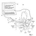
- FIG. 1illustrates an overview of the endovascular device guiding apparatus and method disclosed in the present invention.
- FIG. 2illustrates an endovascular device with multiple sensors.
- FIG. 3A-3Billustrates an intravascular ECG electrode which can be used for steering and moving the endovascular member away from the vessel wall.
- FIG. 4A-4Cillustrates the concept of removable sensor core, whereby a stylet with integrated sensors can be inserted into and removed from an endovascular device like a catheter at any time.
- FIG. 5A-5Billustrates an embodiment integrated sensors in an endovascular device with braided shaft and atraumatic tip.
- FIG. 6illustrates another embodiment of integrated sensors in an endovascular device with stylet-like reinforcement that can be used as an ECG electrode.
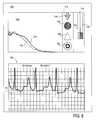
- FIG. 7illustrates the flow velocity profiles, the intravascular ECG signal and their correlation as detected by the device according to the present invention in the superior vena cava as documented by the synchronized fluoroscopic image.
- FIG. 8illustrates the flow velocity profiles, the intravascular ECG signal and their correlation as detected by the device according to the present invention at the caval-atrial junction as documented by the synchronized fluoroscopic image.
- FIG. 9illustrates the flow velocity profiles, the intravascular ECG signal and their correlation as detected by the device according to the present invention in the internal jugular vein as documented by the synchronized fluoroscopic image.
- FIG. 10illustrates the use of intravascular ECG signal to gate or trigger the acquisition or processing of the blood flow information.
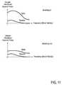
- FIG. 11illustrates the effect of using additional gating based on patient's breathing on the acquisition and processing of blood flow information.
- FIG. 12illustrates the use of intravascular ECG signals in case of a-fib patients.
- FIG. 13illustrates a graphical user interface displaying blood flow information, intravascular ECG signals, their correlation, and catheter tip location information based on the above.
- FIG. 13also illustrates the use of A-mode imaging for clot identification inside the blood stream or inside an endovascular member.
- FIG. 14A-14Dillustrates a simplified user interface using blood flow information, intravascular ECG signals and their correlation to display if the endovascular member is advancing towards the caval-atrial junction and sinoatrial node, if the endovascular member is advancing away from the caval-atrial junction and sinoatrial node, or if the endovascular member is at the caval-atrial junction proximal to sinoatrial node.
- FIG. 15is a flow chart of an exemplary endovascular placement method.
- FIG. 16illustrates an endovascular device within the vasculature at various locations according to the method of FIG. 15 .
- FIGS. 17 and 18are various views of the heart and surrounding vasculature.
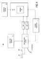
- FIG. 19is a flow chart illustrating the functioning of a data acquisition system of FIG. 6 .
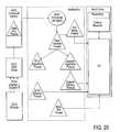
- FIG. 20is a flow chart illustrating an exemplary software block diagram of FIG. 6 .
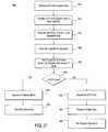
- FIG. 21is a flow chart illustrating an exemplary processing algorithm for multi-parameter signal processing and correlation.
- FIG. 1illustrates one embodiment of an exemplary endovascular access and guidance system 100 .
- the system 100includes an elongate body 105 with a proximal end 110 and a distal end 115 .
- the elongate body 105is any of a variety of endovascular devices adapted to insertion into and navigation through the vasculature of the patient 1 .
- FIG. 1illustrates the distal end 115 inserted into the basilic vein 6 .
- the expected path of travelin this illustrative example is into the a portion of the heart 20 or within the superior vena cava 14 in proximity to the sinoatrial node (SA node) 8 .
- SA nodesinoatrial node
- the aorta 3 , the pulmonary arteries, pulmonary veins 11 , the jugular veins 10 , the brachiocephalic vein 12 , inferior vena cava 16 and atrioventricular node (AV node) 9are also represented in this view.
- the elongate body 105includes at least two sensors for measuring physiological parameters in the body.
- one sensoris a non-imaging ultrasound transducer on the elongate body 105 configured to provide in vivo non-image based ultrasound information of the vasculature of the patient 1 .
- the other sensoris an endovascular electrogram lead on the elongate body 105 in a position that, when the elongate body 105 is in the vasculature, the endovascular electrogram lead electrical sensing segment provides an in vivo electrogram signal of the patient 1 .
- FIG. 1illustrates the use of a second electrogram sensor that is outside of the vasculature.
- the electrode 112is positioned external to the vasculature of the patient 1 .
- the electrode 112detects electrogram information that is transmitted via lead 111 to the processor 140 .
- another electrogram sensormay be placed on the elongate body 105 in place of the electrode 112 or in addition to the electrode 112 .
- More than one electrogram sensormay be provided on the elongate body.
- the processor 140would also be configured to receive, process, compare and correlate the electrogram information from the additional electrogram sensor (or other sensors) provided by the elongate body 105 .
- the electrogram leads or sensors on the elongate body 105may also be placed relative to the elongate body 105 and to one another in order to obtain a target electrogram signal and a baseline electrogram signal in order to facilitate the position and location capabilities of the guidance system 100 .
- the target and baseline electrogram informationmay be related to one or more of: (a) electrical activity of the heart including all or a portion of an electrocardiogram (ECG); (b) electrical activity of the brain including all or part of an electroencephalogram (EEG); and (c) electrical activity of a muscle or muscle group including all or part of an electromyogram (EMG) related to that muscle or muscle group. Additional details of the sensors and the various alternative configurations of the elongate body 105 are described below in at least FIGS. 2-5B .
- the system 100also includes a processor 140 configured to receive and process a signal from the non-imaging ultrasound transducer and a signal from the endovascular electrogram lead.
- the processor 140includes conventional processing capabilities to receive and process ultrasound and electrogram signals as with conventional ultrasound and electrogram signals.
- the conventional processing capabilitiesinclude those conventional components needed to receive process and store the corresponding sensor data. If sensors on the elongate body are used to detect ECG activity, then appropriate electrocardiography components and processing capabilities is provided. The same is true for EEG signal processing, EMG signal processing, acoustic sensor processing, pressure sensor processing, optical sensor processing and the like.
- processor 140includes programming and processing capabilities to process the signals from the sensors to identify and correlate flow and electrical patterns to aid in the guidance, positioning and confirmation of location of the elongate body 105 as described herein.
- the processor 140is adapted and configured using software, firmware or other programming capabilities to receive and process a signal from the non-imaging ultrasound transducer that contains at least one signal of the group consisting of: a venous blood flow direction, a venous blood flow velocity, a venous blood flow signature pattern, a pressure signature pattern, A-mode information and a preferential non-random direction of flow. Additionally, the processor 140 is further adapted and configured using software, firmware or other programming capabilities to receive and process a signal from the endovascular electrogram lead that contains at least one signal from the group consisting of: an electrocardiogram signal, a P-wave pattern, a QRS-complex pattern, a T-wave pattern, an EEG signal and an EMG signal.
- the signal from one sensoris the trigger for acquisition or processing of a signal from another sensor.
- the data from two different physiologic sensorsmay be correlated in time and to the trigger signal.
- all sensor datacould be collected and/or stored and the trigger could instead result in the processing of only the subset of the data based on the trigger data.
- the trigger sensor data and the triggered sensor dataare processed together to yield the benefits described below.
- One example of triggeringis the use of the P-wave detection from an electrogram sensor as the triggering signal for acquiring ultrasound data from an ultrasound sensor.
- the unique P-wave signal detected when an electrogram lead is positioned in the superior vena cava near the sino-atrial node 8can be used to confirm the detection of the unique blood flow pattern that also occurs in this area of the vasculature. In this way, the existence of both unique physiological signals from two different physiological systems increases the accuracy of the guidance system embodiments described herein.
- the system 100also includes an output device 130 configured to display a result of information processed by the processor 140 .
- the display devicemay, like the processor 140 , include capabilities found in conventional display devices.
- the display device 140 of the inventiondiffers from the conventional display in that the display is configured to display information related to the unique processing and results determined by processor 140 .
- the output device 140displays a result related to a position of the elongate body within the vasculature of the patient.
- a result of information processed by the processorincludes an indication of a position or a movement of the elongate body 105 within the vasculature based on in vivo non-image based ultrasound information and in vivo electrogram information.
- the display 130would be configured to display this information for a user to perceive in any suitable manner such as visually, with colors, with pictograms, with sounds or in other appropriate manners.
- embodiments of the inventionrelate to the use of intravascularly measured physiological parameters for locating, guiding, and placing catheters in the vasculature.
- embodiments of the present inventionrelate to an endovascular member assembly with built-in sensors for measuring of physiological parameters such as blood flow, velocity, pressure, or intravascular ECG.
- embodiments of the inventionrelate to data processing algorithms that can identify and recognize different locations in the vasculature based on the pattern of physiological parameters measured at that location.
- embodiments of the present inventionrelate to data processing algorithms that can identify and recognize structures such as objects of interest in the vasculature or in endovascular members, e.g., blood clots based on the pattern of parameters measured, e.g, A-mode and blood flow velocity.
- embodiments of the present inventionrelate to an instrument that has a user interface which shows guiding and positioning information and presents the objects of interest, e.g., blood clots.
- the processoris further configured to process a signal from the non-image ultrasound transducer and to indicate in the output device information related to the presence of a structure in the field of view of the non-imaging ultrasound transducer.
- embodiments of the inventionrelate to the method of guiding and positioning an endovascular member within the vasculature by the user based on location information provided by the sensor-based endovascular member.
- Other various aspects of embodiments the inventionrelate to the use of intravascularly measured physiological parameters for locating, guiding, and placing catheters or stylets or guide wires for use as guides to particular locations within the vasculature that have been identified using the guided vascular access devices and systems described herein.
- the present inventionprovides a new methods, devices and systems for intravascular guidance and placement of endovascular devices based on the recognition of patterns in the signals for different physiological parameters and correlation of those signal patterns.
- a cathetersuch as a peripherally inserted central catheter (PICC) is inserted, advanced, positioned and monitoring within the vasculature based on the recognition of blood flow patterns, of the electrocardiogram signals and of their correlation at the locations of interest.
- PICCperipherally inserted central catheter
- One benefit of the new apparatus and method introduced hereinis that it increases the probability of correct placement of an endovascular device in a placement procedure performed at the bedside. Moreover, because of the accuracy and redundancy of the positioning methods described herein, it is believed that the use of the inventive methods, devices and systems will allow for endovascular device placement without the need for imaging guidance, in particular without X-ray imaging and/or imaging for confirmation of placement and lack of device migration. Another benefit of the new apparatus and method introduced herein is that it allows the detection of blood clots in the vasculature or in catheters such identifying the cause for a malfunctioning catheter, e.g., a central line.
- embodiments of the inventionprovide new sensor based endovascular devices, systems and methods for intravascular guidance and placement of, for example, sensor based catheters and/or guide wires.
- the properly positioned sensor based endovascular deviceis used to then guide the deployment of other endovascular devices or facilitate the performance of other diagnostic or therapeutic procedures in the body such as, for example: (a) location of heart valves for replacement heart valve procedures; (b) identification of the renal veins for therapy in those veins or in the kidneys; (c) identification of renal veins and/or the inferior vena cava for IVC filter placement; (d) location of coronary sinus for placement of pacing leads or mitral valve modification devices; and (e) location of pulmonary veins for sensor placement and/or performance of therapy such as ablation treatment for atrial fibrillation; as well as a wide variety of other diagnostic or therapeutic procedures that would benefit from the placement of device or performance of therapy at specific locations in the vasculature identified by the sensor correlation techniques described herein.
- other diagnostic or therapeutic proceduressuch as, for example: (a) location of heart valves for replacement heart valve procedures; (b) identification of the renal veins for therapy in those veins or in the kidneys; (c) identification of renal
- the systems and methods of embodiments of the inventive guidance system described hereinare utilized to locate, guide and position catheters and/or guide wires equipped with sensors described herein within the vessels of the venous system.
- the embodiments described hereinmay also be utilized in the vessels of the arterial system as well.
- the guided vascular access devices described hereinmay be used for the guidance, positioning, and placement confirmation of intravascular catheters used in a wide number of clinical applications.
- Exemplary clinical applicationsthat would benefit from embodiments of the invention include the placement of, for example, central venous access catheters (PICC), hemodialysis catheters and the placement of catheters, positioning of endovascular devices in the vasculature of the brain for treatment of stroke, placement of leads or other brain based therapy or therapy devices or treatment systems for percutaneous treatment of varicose veins.
- PICCcentral venous access catheters
- particular muscles or muscle groupsmay be selected for EMG stimulation and/or sensor collection in support of one of more methods and devices described herein where the EMG signals are used to confirm and/or correlate a position in the vasculature. This aspect may be particularly helpful when identifying portions of the vasculature in the legs for localization of varicose veins, localization of the femoral veins or positioning of a vessel harvesting device within the great saphenous vein, for example.
- certain locations in the vasculaturecan be identified by specific blood flow and electrogram patterns, electrogram signal patterns and correlation between these blood flow patterns at those locations. These patterns may be based on, for example, blood pressure, Doppler blood flow measurements, and intravascular electrocardiogram. Moreover, it is believed that the direction of travel for an sensor equipped endovascular device can be determined relative to the direction of blood flow by using the Doppler effect, relative changes in the intravascular electrogram signal and in the correlation between the blood flow and electrogram information.
- PICCPeripheral Inserted Central Catheter
- a userby determining and real-time monitoring the direction of the catheter movement in the blood vessels using the sensors, techniques, data acquisition and processing described herein (for example blood flow and electrogram information), a user receives feedback on advancing a guided vascular access device to allow the PICC to advance along a desired path from an insertion vein into the vena cava and towards the sinoatrial node.
- the systemmay also recognize unintended entry into other veins because of the differences in flow patterns signals and electrogram signals or other signals received from the sensors. As such, the system may recognize unintended entry into the right atrium, inferior vena cava, jugular vein, the subclavian vein.
- the systemmay detect when a sensor is against the vessel wall. By monitoring the data acquired from sensors positioned on the endovascular access device, the user can be notified when the device tip reaches the ideal placement in the lower third of the superior vena cava, at the caval-atrial junction and/or in the proximity of the sinoatrial node.
- the systemrecognizes these locations of the vena cava, and other vascular components, by analyzing sensor acquired data to identify unique flow patterns and electrogram signatures and to correlate these unique signatures in order to confirm placement, location and/or guidance.
- the ultrasound technology described hereinis a non-imaging ultrasound used in combination with intravascular electrograms, or other physiological parameter sensor data.
- the unique flow patternsmay be discerned using non-imaging ultrasound and as such does not require all the elements that make ultrasound imaging possible, such as scanning with a moving transducer or working with phased arrays and beam forming, and the like.
- embodiments of the present inventionprovide a vascular access and guidance system with a hand-held, simple, inexpensive user interface.
- Non-imaging ultrasoundincludes a number of various ultrasound techniques and processing configurations, by way of non-limiting example: A-beam ultrasound, Doppler ultrasound, continuous wave Doppler ultrasound, pulsed Doppler ultrasound, color Doppler ultrasound, power Doppler ultrasound, bi-directional Doppler ultrasound, and ultrasound techniques that provide for the determination of velocity profile based on correlation of blood flow and time.
- multi-vectorrefers to the use of the blood flow information, the electrical activity information and the relationship between the two.
- the physiological informationis analyzed in order to identify the location in the vasculature where the information was acquired. Because body functions are unique at certain corresponding unique locations in the vasculature, embodiments of the present invention can use measurements of the body functions and detect location in the body.
- the present inventiondescribes the use of the blood flow profile and of the intravascular ECG to detect the proximity of the sinoatrial node and of the caval-atrial junction.
- FIG. 17illustrates the anatomical location of the caval-atrial junction at the confluence between the superior vena cava (SVC) and inferior vena cava (IVC just before entering the right atrium (RA).
- FIG. 18illustrates the anatomical location of the sinoatrial node at the caval-atrial junction.
- the function of the vasculature and the function of the heartare unique at the caval-atrial junction both in terms of blood flow profile and of electrical activity of the heart.
- the system according to the present inventionidentifies the blood flow profile characteristic of the caval-atrial junction and ECG waveform patterns characteristic of the proximity of the sinoatrial node and, when both these patterns are present, indicates to the user that the desired target location has been reached.
- One benefit of this approachis that the blood flow and the electrical activity are independent physiological parameters and thus by considering them together, the accuracy of the location information is significantly improved.
- the intravascular electrogram signalcan be used for selective (gated) acquisition and processing of the blood flow information, depending upon the specific characteristics of the electorgram signal being utilized. For example when the electrogram signal is produced by the heart from the gating acquisition may be based on one or more integrals of the heart cycle. This selective approach also increases the accuracy of determining blood flow patterns corresponding to locations in the vasculature.
- FIG. 2illustrates an endovascular device 150 having an elongate body 105 with a proximal end 110 and a distal end 115 .
- a non-imaging ultrasound transducer 120on the elongate body 105 .
- an atraumatic tip 121on the endovascular device 150 .
- the atraumatic tip 121may also include an ultrasound lens.
- the ultrasound lensmay be used to shape the ultrasound signal produced by the ultrasound transducer 120 .
- the ultrasound lensis a divergent lens.
- the endovascular device 150also has an opening 182 in the elongate body 105 and a lumen within the elongate body 105 in communication with the opening 182 and the elongate body proximal end 110 . As illustrated, there may be one or more openings 182 in communication with one or more lumens or tubes 183 . Also shown on the proximal end 110 are the various connections to the sensors and lumens in the endovascular device 150 . These connections are conventional and may take any suitable form to connect the endovascular device to the other guidance system 100 components such as the processor, display or fluid delivery device.
- the elongate body 105 or endovascular device 150is adapted to deliver a therapy to the patient such as by delivering drugs, therapeutic or diagnostic agents through the openings 182 or between the inner and outer tubes.
- the elongate body 105 or the endovascular device 150is adapted to provide endovascular access for another device.
- the endovascular device 150also illustrates how other additional and optional sensors may be provided.
- Embodiments of the endovascular device 150may contain any of a number of different sensors.
- the sensoris selected based on the physiological parameter to be measured and used in the guidance, positioning and correlation methods described herein.
- the devicemay include an ultrasound sensor, a conductive wire, a pressure sensor, a temperature sensor, a sensor for detecting or measuring electrical potential and voltages and other sensors suited to collecting physiological information and providing information to the processor 140 for processing in an algorithm or for other suitable form of analysis based on the techniques described herein.
- the sensor-based endovascular device 150can be used independently to deliver a payload into the vasculature, e.g., a drug or to draw blood or it can be inserted into the one of the lumens of another endovascular device, e.g., a catheter. Then the entire assembly can be inserted into the patient's body, e.g., for a PICC placement procedure, or through a catheter 90 (see FIG. 4C ).
- the endovascular device 150can be configured as any type of catheter, stylet, guidewire, an introducer, a combination thereof or any other type of device which allows for vascular access.
- the endovascular device and the corresponding connection from the sensors to the proximal endcan either be fixed in the endovascular device, or pre-inserted and removable after procedure, or reinsertable for location verification post placement.
- the endovascular deviceintegrates a single lead electrode for electrical activity monitoring.
- the endovascular devicemay integrate several electrodes (leads), for example one at the very distal tip of the endovascular member and one more proximal such that the distal electrode can detect the electrical activity of the heart while the more proximal electrode can serve as a reference for measuring since the more proximal electrode is closer to the patient's skin and further away from the heart.
- the lead/electrodecan be used as a steering element to steer and position the endovascular device as illustrated in FIGS. 3A , 3 B, 4 A and 4 B.
- physiological informationis acquired by sensors and transmitted to a processor.
- the processoruses algorithms which analyze and process the sensor data to provide information on the location of the sensor core assembly and of the corresponding endovascular device in the patient's vasculature. Since high degree of accuracy is desired, different types of physiological information, ideally independent from each other, such as blood flow information and electrogram information are used to accurately characterize the direction of movement and location.
- the described clinical needis met by gathering physiological information regarding blood flow using ultrasound and regarding the electrical activity of the heart by acquiring endovascular electrical signals.
- the endovascular device embodiments of FIGS. 3A , 3 B, 5 A, 5 Bconsists of an elongate body 105 that may be configured as any of a catheter, a stylet, or a guidewire that is configured for endovascular access.
- the catheter, stylet or guidewiremay be of the one part or two part construction described herein.
- the endovascular device 150may be configured as a single structure ( FIGS. 3A , 3 B, 4 A, 4 B, 5 A and 5 B, also be a removable device or sensor core assembly may consist of a non-imaging ultrasound transducer mounted at the end of a piece of tubing.
- the tubingcan be single or multi-lumen and can be made of any of a variety of polymeric, or elastomeric materials.
- the lumensmay be used to support the sensors on the tubing or may be used for delivery of therapeutic or diagnostic agents.
- One or more physiological parameter monitoring sensorsmay be positioned on the tubing as described herein.
- the endovascular devicemay have a two part construction as shown in the illustrative embodiment of FIG. 2 where the ultrasound transducer is on a tube (an inner tube) within another tube (an outer tube).
- the inner tubecarries the ultrasound transducer.
- the outer tubepossibly a multi-lumen tube, has a lumen for the inner tube. Additionally, lumens 183 are provided to correspond to the openings 182 .
- the outer tubealso supports the additional sensors (one sensor 186 is shown). The wiring or other connections for the additional sensors 186 or electrogram lead may also be provided with their own lumen or lumens.
- the proximal end 110 and the various leads and lumens and other connectionsmay be placed into a single connector used to attach the endovascular device 150 to the other components of the system 100 .
- the deviceinclude an additional sensor 186 on the endovascular device for measuring a physiological parameter.
- the additional sensoris an optical sensor and the physiological parameter is related to an optical property detected within the vasculature.
- the additional sensoris a pressure sensor and the physiological parameter is related to a pressure measurement obtained within the vasculature.
- the additional sensoris an acoustic sensor and the physiological parameter is related to an acoustic signal detected within the vasculature.
- endovascular electrogram lead 130on the elongate body 105 in a position that, when the endovascular device 150 is in the vasculature, the endovascular electrogram lead 130 is in contact with blood.
- an electrogram lead 130contains at least one electrical sensing segment 135 .
- the electrical sensing segment 135is that portion of the electrogram lead 130 that is used for detecting or sensing the electrical activity being measured.
- the electrical sensing segment 135could be a portion of the lead 130 that is not insulated, it could be a separate structure, like an electrode, that is joined to the lead 130 or it could be a structure within the endovascular device (see FIG. 5B ).
- the electrical sensing segment of an endovascular electrogram leadis positioned within 3 cm of the elongate body distal end 115 .
- the electrical sensing segment 135 of an endovascular electrogram lead 130is positioned within 3 cm of the non-imaging ultrasound transducer 120 .
- this aspectrelates to the lead 130 that extends from the distal end or to the spacing of proximally positioned endovascular lead 130 . Additionally or alternatively, the electrical sensing segment 135 of an endovascular electrogram lead 130 is positioned proximal to the non-imaging ultrasound transducer 120 .
- FIG. 2also illustrates an endovascular device with a second endovascular electrogram lead 135 on the elongate body 105 .
- the second endovascular leadis shown in a position that, when the endovascular device 150 is in the vasculature, the second endovascular electrogram lead 130 is in contact with blood.
- Endovascular leads 130(and/or the corresponding electrical sensing segment or segments 135 ) may extend from the elongate body 105 as shown in FIGS. 2 and 3A or may be integral to or within the elongate body as shown in FIGS. 3B , 4 A, 4 B 5 A, and 5 B.
- the electrical sensing segment 135 of the second endovascular electrogram lead 130(the proximal electrogram lead 130 in FIGS. 2 and 4B ) is positioned about 5 cm from the other endovascular electrogram lead 130 .
- electrical sensing segment 135 of the second endovascular electrogram lead 130is positioned about 5 cm from the elongate body distal end 115
- the use of two electrogram leadscan be used to enhance the measurement accuracy of the electrical signals being used in the guidance system.
- the electrical sensing segment of the second endovascular electrogram leadis positioned at a distance spaced apart from the endovascular electrogram lead so that the second endovascular electrogram lead detects a baseline electrogram signal when the endovascular electrogram lead is detecting a target electrogram signal.
- the systemmay rely completely on electrical signals completely within the vasculature to obtain a baseline measurement thereby eliminating the need for an external sensor as shown in FIG. 1 .
- the electrical sensing segment of the second endovascular electrogram leadis positioned such that when the electrical sensing segment of the endovascular electrogram lead is positioned to detect a targeted electrogram signal from the heart the electrical sensing segment of the second endovascular electrogram lead is positioned to detect a comparison baseline ECG signal.
- the electrical sensing segment of the second endovascular electrogram leadis positioned such that when the electrical sensing segment of the endovascular electrogram lead is positioned to detect a targeted electrogram signal from the brain the electrical sensing segment of the second endovascular electrogram lead is positioned to detect a comparison baseline EEG signal.
- electrical sensing segment of the second endovascular electrogram leadis positioned such that when the electrical sensing segment of the endovascular electrogram lead is positioned to detect a targeted electrogram signal from a muscle the electrical sensing segment of the second endovascular electrogram lead is positioned to detect a comparison baseline EMG signal.
- the spacing between the electrogram leadsis related to the target anatomy or anatomical structures.
- the electrical sensing segment of the second endovascular electrogram leadis positioned at a distance related to the length of the superior vena cava such that when the endovascular electrogram lead is in the superior vena cava the second endovascular electrogram lead is outside of the superior vena cava.
- one leadwould be near a target region of the brain or a muscle and the second would be positioned so that it would detect baseline electrical levels.
- the conductive element for an electrogram leadcan be made up of any suitable biocompatible conductive material such as stainless steel, a saline column or SMAs (smart memory alloys or shape memory alloys), e.g., nitinol.
- SMAssmart memory alloys or shape memory alloys
- Typical diameters of the conductive elementare between 0.005′′ and 0.010′′.
- Typical lengths of the conductive element or the endovascular deviceare between 1 and 8 feet.
- the conductive elementis sized and configured to perform multiple functions or functions in addition to signal detection and transmission.
- the conductive element or electrogram leadmay be used for steering, tip positioning, and others.
- FIGS. 3A and 3Billustrate an embodiment of an endovascular device 150 with an elongate body with a proximal end and a distal end. There is a non-imaging ultrasound transducer on the elongate body. There is an endovascular electrogram lead on the elongate body in a position that, when the endovascular device is in the vasculature, the endovascular electrogram lead is in contact with blood.
- the electrical sensing segment 135is positioned to detect an electrogram signal.
- the electrical sensing segment 135is positioned in the window 170 and can access blood.
- the window 170is an opening into a lumen within the elongate body that forms a sliding seal about the electrogram lead 130 . In this way, blood in contact with the window and the lead is prevented from flowing down the interior of the elongate body.
- the endovascular electrogram lead 130is moveable from a stowed condition within the elongate body ( FIG. 3B ) and a deployed condition outside of the elongate body ( FIG. 3A ).
- the electrogram lead or conductive elementcan be deployed through a side opening or window 170 in the sidewall of the elongate body 105 .
- the window 170is positioned at or near the distal end of an endovascular member.
- the electrogram lead 135also serves the purpose of being able to distance the tip 115 or the ultrasound sensor 121 of the endovascular member away from the inner wall of the blood vessel. In this way, the endovascular electrogram lead is adapted for use to move the ultrasound sensor away from a blood vessel wall.
- the deployed shape of the electrogram lead 135 shown in FIG. 3Amay include shapes that curve completely or partially about the elongate body 105 and may be positioned proximal to the distal end, span the distal end or be positioned distal to the distal end.
- the electrogram lead 135is formed from a shape memory metal or material that is appropriately pre-set into the desired deployed shape.
- the endovascular lead 130is made of nitinol.
- the endovascular lead 130may also include an atraumatic tip 139 .
- the atraumatic tip 139may be formed from the electrogram lead (a curved end, shaped end or rounded end) or may be a separate structure attached to the distal end to provide the atraumatic capability.
- the endovascular electrogram 130may be used to perform a number of additional and optional functions. As shown in FIG. 3B , when the endovascular electrogram lead is in the stowed condition, the lead curves the distal end 115 . In this configuration, a steering element (such as those shown in FIGS. 4A and 4B ) may be used to turn, twist or apply torque to the elongate body using the endovascular lead 130 . In this way, the endovascular electrogram lead 130 may also be used for steering, placement or other guidance requirements of the user.
- a steering elementsuch as those shown in FIGS. 4A and 4B
- FIGS. 4A and 4Billustrate alternative exemplary embodiments of an endovascular device referred to as a sensor core assembly.
- the sensor core assemblyderives its name from the compact size that allows it to be inserted into or ride along with in a lumen on or in another endovascular device.
- the functionality and advantages of the systems and methods described hereinmay be applied to a wide variety of devices positioned within or used within the vasculature.
- the sensor core assemblycan be pre-inserted (if used for guidance and initial placement) or later inserted (if used for position confirmation) into one of the lumens (inside or alongside) of another endovascular device, e.g. in into a PICC catheter.
- the endovascular devices illustrated in FIGS. 4A and 4Balso illustrate a steering element 153 on the proximal end.
- the steering elementmay be used to rotate one or both of the elongate body, a steering element in the elongate body or an electrogram lead 130 configured for concurrent use as a steering element.
- the userwould grasp the steering element 153 and manipulate as needed to produce the desired movement of the elongate body, the distal tip or the endovascular device.
- the steering mechanism 153 and the endovascular lead 130may also be sized and configured that the lead, turned by the steering mechanism may apply torque or impart rotation to the elongate body or otherwise facilitate manipulation, steering or control of the endovascular device.
- FIGS. 4A and 4Billustrate a connector or hub 154 on the proximal end that provides an appropriate and consolidated connection point for the sensors and other components of the endovascular device to the guidance system 100 .
- the connector 154 and steering device 153may be adapted and configured to allow relative movement between them so that the steering element 153 may be used without interrupting the connectivity provided by the connector 154 .
- FIG. 4Cis a conventional catheter 90 with a body, a distal end 95 , a catheter hub 97 on the proximal end.
- a lumen 96extends from the distal end, though the body and hub into communication with the tubes 92 and fittings 91 a , 91 b .
- the endovascular device 150FIGS. 4A and 4B ) may be inserted directly into the patient vasculature and guided as described herein to a target site. Thereafter, the catheter 90 (or other device for placement) is run over the device 150 until in the desired position.
- the endovascular device 150 or sensor core assemblycan be inserted in the lumen of an endovascular device (lumen 96 of catheter 90 ) which is then inserted into the patient's body and guided based on sensor inputs from the endovascular device 150 .
- the elongate body 105is itself conductive using a metal wire or has integrated a conductive element such that it can detect electrical activity of the body and transmit resulting electrical signals to the proximal end of the member.
- the proximal end of the conductive elementcan be attached to a system for signal processing and graphical user interface.
- the attachments for the various sensors and components of the endovascular device 150may be wired or wireless connections may be used.
- FIG. 5Bis illustrates an endovascular device 150 b with an elongate body 105 with a proximal end and a distal end.
- a non-imaging ultrasound transduceron the elongate body 120 and an endovascular electrogram lead on the elongate body in a position that, when the endovascular device is in the vasculature, the endovascular electrogram lead is in contact with blood.
- the elongate body 105comprises a coated metal braided structure 172 as best seen in the cut away portion of FIG. 5B .
- There is a coating 159(typically an insulating coating may of a biocompatible polymer) over the metallic or conductive braided structure 172 .
- a portion of the coating 159 on the metal braided structure 172is removed (providing a window 170 ).
- the exposed metal braided structurei.e., that portion exposed in window 170
- the remained of the braid 172functions as the lead to transmit the signals detected by the exposed section back to the processor or other components of the guidance system 100 .
- the tubemay be metallic or metal braid encapsulated by polymeric material.
- a polymeric materiallike PTFE or polyimide and a polymeric compound, e.g., polyimide and graphite or glass fiber can be used.
- a separate structuresuch as a spring, a wire or a mesh wire, made with stainless steel or nitinol for example, may also be inserted into or formed within the inner lumen of the sensor core tube to provide additional column strength and resistance to kinking or extreme bending to the sensor core tube.
- the separate wirecan also be used for conducting electrical signals generated by the patient.
- FIGS. 5A and 5Bdemonstrate examples of these designs.
- the sensor core assemblymay contain a polymeric tube 159 .
- the outer diameter of the tubemay be from 0.010′′ to 0.030′′, the inner diameter from 0.008′′ to 0.028′′.
- the polymeric tubemay be coated, for example with PTFE.
- the transducerwhich can be 0.010′′ to 0.030′′ in diameter is fixed at the distal end of the sensor core assembly with Doppler-transparent adhesive or epoxy which can also be used as a lens or a plurality of microlenses to optimize the ultrasound beam profile.
- the separate wire or electrogram leadcan be made with any conductive material, e.g., nitinol, stainless steel, and is suitably connected to transmit detected electrical signals to the proximal end of the sensor core assembly and to components of guidance system 100 .
- the separate wiremay consist of one continuous conductive element or several conductive elements that are connected together.
- the conductive element 130 / 135is provided by a braid which is used to reinforce the shaft of the endovascular device.
- the braidcan be made of any conductive material, e.g., stainless steel or nitinol, and can have any kind of geometries and number of wires.
- the braidis exposed at the distal end of the endovascular device to allow contact with blood and therefore be capable of detecting electrical activity.
- the braidservers as a reinforcement layer and therefore is electrically isolated from both the inner and the outer sides.
- the tubing used for sensor core assemblycan be made with a sleeve which has a mesh in a braid or coil form encapsulated by polymeric material.
- the sleevemay or may not have a polymeric material only stem at its ends.
- the meshcan be made with any conductive material, such as Nitinol or stainless steel, and needs to be able to transmit electric signal from the distal end to the proximal end of the sensor core assembly.
- the meshmay consist of one or multiple types of conductive elements and can be made with one or multiple conductive or non-conductive materials.
- the meshmay also consist of one or multiple types of continuous conductive element or several conductive elements that are connected to each other.
- a separate polymeric sleeve or other isolating materialcan be used to isolate the wire attached to the Doppler sensor (coaxial or twisted pair wire or grounded twisted pair wire or any other type of conductive element) from contact with biological fluid, blood or tissue.
- a Doppler-transparent atraumatic tipcan also be added to the distal end of the sensor core assembly. The Doppler-transparent atraumatic tip can also be used as a beam-shaping element for the ultrasound beam.
- FIG. 6illustrates a system 100 that can be used to guide catheter placement using non-imaging ultrasound based blood flow information and electrical activity of the body.
- the system 100is used to place an endovascular device 150 in the superior vena cava 14 using blood flow and ECG patterns and relative to the sinoatrial node 8 using intravascular ECG.
- An exemplary display 140 and/or user interfaceis shown in FIGS. 7 , 8 , 9 , 13 , 14 A and 14 D and is described below.
- the system 100integrates a data acquisition system, two DAQ cards, an isolation transformer and a computing platform, e.g., a PC which has software loaded to process the signals and display information on a screen.
- the data acquisition system and the PCare powered from a common Isolation Transformer or other suitable power supply.
- the data acquisition system ( 1 )is capable of acquiring ultrasound signals and electrical signals generated by the body activity, such as electrogram (ECG, EEG and/or EMG) including intravascular and intracardiac electrocardiogram signals.
- ECGelectrogram
- EEGelectrogram
- EMGelectrogram
- a sensor-based endovascular device 150 as described hereincan be connected to the data acquisition system ( 1 ).
- An additional ECG lead 112can be attached to the patient's skin (see FIG.
- the optional speaker ( 11 )is used to optionally convert Doppler frequencies, i.e., blood velocities into audible signals or to otherwise provide signals or instructions to inform a user of the position of the device 150 .
- One analog-to-digital converter ( 8 )is used to digitize ultrasound signal information and transfer it to the processor 140 or other suitable computing platform for processing.
- a second analog-to-digital converter ( 9 )is used to digitize electrogram signals coming from the electrogram lead on the endovascular device and from the reference electrode (either outside or inside the vasculature). Other or additional A/D converters may be provided based on the sensors used in the device 150 .
- the computing platform ( 4 )can be a generic one like a personal computer or a dedicated one containing digital signal processors (DSP).
- the computing platformserves two purposes. It provides the processing capabilities of the processor 140 that allows data processing algorithms ( 5 ) to run.
- the various data processing algorithms employed by the various methods of embodiments of the current inventionare described in greater detail below.
- the other purpose of the computing platformis to provide “back-end” functionality to the system 100 including graphical user interface, data storage, archiving and retrieval, and interfaces to other systems, e.g., printers, optional monitors ( 10 ), loudspeakers, networks, etc. Such interfaces can be connected in a wired or wireless configuration.
- printersprinters, optional monitors ( 10 ), loudspeakers, networks, etc.
- Such interfacescan be connected in a wired or wireless configuration.
- FIG. 19illustrates more detail of the functional blocks of an exemplary Data Acquisition System 1 (from FIG. 6 ). These components are those found in conventional ultrasound systems.
- FIG. 19The signal flow path illustrated and described with regard to FIG. 19 details how two different physiological parameters may be sampled, acquired and digitalized for processing according to the methods and systems described herein. While FIG. 19 may specific reference to ECG and Doppler, it is to be appreciated that the acquisition, conversion, processing and correlation described herein may be applied generally to ultrasound and electrogram signal combinations including a variety of different ultrasound modes and various different types of sources of electrogram signals. Moreover, ablation, acquisition, conversion, processing and correlation steps, components and capabilities may be included in the system 100 as needed depending upon the type and number of sensors employed on the endovascular device 150
- the ultrasound transducer (TXD) 120which can be driven as Doppler and A-mode imaging is attached to a transmit/receive (T/R) switch to support pulsed wave operation.
- T/Rtransmit/receive
- the Pulser blockgenerates the ultrasound signal used to drive the transducer 120 . Exemplary signals are between 7-14 MHz.
- the Tx pulser tableis firmware which allows the system to define the exact shape of the pulse train generated by the Pulser.
- the Programmable Gain (TGC) blockimplements variable gain, in particular useful for time-depth gain compensation.
- the Analog Filteris a band-pass filter used to filter out unwanted high and low frequency signals, e.g., noise and harmonics.
- the Rx Gate and TGC Control blockis used to select the sample volume range (depth) and width, i.e., the target volume from where the incoming (i.e. reflected) ultrasound signals are acquired.
- the sample volume range (depth) and widthdefines the blood pool volume which is analyzed for velocity information.
- the rangeextends from the transducer face to the entire available depth of penetration, and maximum width.
- the Rx Gate and TGC Controlis used to control the TGC block for the appropriate values with respect to the range and width of the sample volume.
- the ADC blockconverts the incoming analog signal into digital signal. Typical values for the high frequency A/D conversion are 12 bit depth of conversion and more than 100 MHz conversion rate.
- the FIFO blockcontains ultrasound digitized data corresponding to the sample volume as selected by the Rx Gate and TGC control block.
- the System Interface block(CPU) allows for the following functional blocks to be programmed algorithmically or by the user via a general purpose computer (CPU): Tx Pulse and Pulser Table, Rx Gate and TGC Control, and the Cos/Sin Table.
- the Cos/Sin Tableis a building block that is used for the quadrature demodulation of the high frequency signal.
- the quadrature demodulation Cos/Sin tablecan be implemented either in software as a DSP (digital signal processor) function or as firmware in an FPGA (field programmable gate array).
- the Mixermultiplies the incoming signal with qudratue cos and sin signals to obtain 90 degrees phase shifted signals which allow for extracting the Doppler frequency shift from the incoming signal.
- the Mixer blockcan be implemented either as a DSP or an FPGA function.
- the FIR (finite impulse response) filteris used to filter the directional Doppler signals.
- An interfaceis provided to transfer digital ultrasound and electrogram (or other sensor) information to the host computer (CPU). The interface can interface either as a standard USB interface (shown in FIG.
- the Power Regulators & Battery Chargerprovides power to the Acquisition System and charge the batteries in a battery-powered configuration.
- the Battery Monitor & Control blockprovides the interface (control and monitor) of the battery and power by the host computer (CPU).
- the electrogram signal pathconsists of two connectors to the endovascular device (leads 130 / 135 ) and/or a reference lead 112 , as needed. The connectors may be optically isolated for patient safety.
- the ECG blockconsists of an amplifier of ECG signals powered by the Isolated Power Supply.
- the ADCdigitizes the ECG signal with 8 to 12 bits at a sampling rate of 100 Hz to 1 KHz.
- FIG. 20illustrates an exemplary software block diagram 4 ( FIG. 6 ) for providing the processing capabilities used by embodiments of the present invention.
- the main software applicationconsists of several real-time threads running concurrently on the host computer platform.
- the ACQ Universal Lib Agentscontrols the acquisition of Doppler and ECG data.
- the Data Transfer Threaddistributes the data to the ECG Algorithm Thread, the Doppler Algorithm Thread and the File Writer Thread.
- the Data Transfer Threadalso ensures synchronization between the ECG and the Doppler data streams, such that, for example, ECG gated/synchronized Doppler analysis can be implemented.
- the File Writer Threadstreams unprocessed real-time Doppler and ECG data to a storage device, e.g., hard disk.
- the benefit of this approachis, that in playback mode, i.e., when reading data from the storage medium through the File Writer Thread, the data can be processed at a later time exactly the same way it was processed at acquisition time.
- the ECG and Doppler Algorithm Threadsimplement real-time feature extraction and decision making algorithms as describes herein.
- the ECG and Doppler Display Threadsdisplay ECG and Doppler information on the graphical user interface (GUI) in real-time.
- the Main GUI Threadis responsible for user interaction, system settings, and thread and process synchronization and control.
- the software applicationsinteract with a number of other components.
- An operating systeme.g., Windows, Linux, or a real-time embedded operating system, e.g. VxWorks provides the infrastructure for the application to run and a number of services, e.g., interface to a database for patient data repository.
- the ACQ Universal Libraryprovides software functions which control the data acquisition hardware.
- the ACQ USB Driver or a TCP/IP network driver or any other kind of communication drivercontrols the communication channel between the Acquisition System (Module) and the host computer platform. Through this bidirectional communication channel Doppler and ECG information is transferred from the ACQ Module and control information is transferred towards the ACQ Module.
- the system according to the current inventionuses two types of physiological parameters detected by the sensor-based endovascular device 150 in order to determine the location of the endovascular device 150 in the vasculature.
- the parametersare ultrasound determined blood flow patterns and intravascular electrocardiogram patterns.
- FIGS. 7 , 8 , and 9are views of a display 130 that illustrate blood flow and electrocardiogram patterns at different locations in the vasculature.
- the display 130 illustrated in FIGS. 7 , 8 and 9includes: a flow velocity profile output 705 ; a bar graph 710 ; a plurality of indicators 715 ; and an electrogram output 720 .
- the flow velocity profile output 705includes a curve 725 related to the flow away from the sensor and a curve 730 related to the flow towards the sensor. The relative power of these flows towards and away are reflected in the bar graph 710 .
- the bar graph 710has an indication 740 for flow towards the ultrasound sensor and an indication 735 for flow away from the ultrasound sensor.
- the bar graph 710may be color coded. One color scheme would represent flow away as green and flow towards as red.
- the systemis able to determine several different states or conditions for the endovascular device 150 .
- the indicators 715are used to represent these conditions to a user viewing the display 140 .
- One indicatormay be used to represent movement of the device 150 in the desired direction.
- the arrow 745when illuminated, indicates proper direction of flow.
- the indicatormay be colored coded, such as green.
- One indicatormay be used to represent improper or undesired movement of the device 150 .
- the octagon shape 750 when illuminatedindicates direction to travel in an undesired direction. This indication may be color coded red. Another indication may be provided to indicate to the user that the system cannot determine or is unsure about device 150 position or movement.
- the triangle 755is used for this indication.
- This indicatormay be color coded yellow.
- Another indicatormay be used to inform a user that the system has determined that the device 150 is in a position where the sensors on the device are detecting signals of the target location when the system detects, for example, blood flow patterns and electrogram signals of the target location, the indicator 760 is activated.
- the indicator 760is one or more concentric rings representing bullseye.
- This indicatormay also be color coded, such as with the color blue.
- the electrogram output 720displays the electrogram signals detected by the electrogram leads used by the system. The outputs displayed each of FIGS. 7 , 8 and 9 correspond to actual data and results obtained using a device and system as described herein.
- each of the ECG displays 720are the same scale to facilitate comparison of the ECG wave from at each position.
- the flow curves 725 , 730(and corresponding relative sizes of the bar graph indications 735 , 740 ) are also representative of actual data collected using the devices and techniques described herein.
- the display 130 illustrated in FIGS. 7 , 8 and 9includes a flow velocity profile 705 bar graph 710 , indicators 715 and an electrogram output 720 .
- FIG. 7illustrates the blood flow velocity profile ( 705 ), the intravascular ECG ( 770 ), indicator 715 (with 745 illuminated) and bar graph 710 when the tip of the endovascular device 150 is in or moving with venous flow towards the superior vena cava (SVC).
- SVCsuperior vena cava
- the ECG 770 in FIG. 7illustrates the typical base line ECG expected in most locations when the device 150 is away from the heart.
- FIG. 8illustrates the blood flow velocity profile ( 705 ), the intravascular ECG ( 770 ), indicator 760 and bar graph 740 when the tip of the endovascular device at the caval-atrial junction.
- the device 150When the device 150 is positioned at a target location, correlation of the various unique signatures of the target location may be used to add confidence to the device position.
- the blood flow toward/away from the sensorare nearly balanced because of the flows converging from the superior vena cava of the inferior vena cava. This nearly equivalent flow toward/away is represented by the proximity of the curves 725 / 730 as well as bars 735 / 740 .
- the ECG 770indicates the prominent P-wave that indicates proximity of the ECG lead to the SA mode. The presence of the larger P-wave is an example of a physiological parameter that is used to correlate the flow information and confirm device placement.
- FIG. 9illustrates the blood flow velocity profile ( 705 ), the intravascular ECG ( 770 ), indicator 715 and bar graph 710 when the tip of the endovascular device is in the internal jugular vein.
- the flow towards the sensornow dominates the velocity profile as reflected in the relative positions of the curves 730 , 725 and the bars 735 , 740 in bar graph 710 .
- the ECG wavedemonstrates a unique QRS polarity (i.e., the QRS complex is nearly equal negative and positive). This distinctive ECG profile is used to confirm that the device 150 has entered the jugular vein. Criteria for feature extraction and location identification can be developed for both the time and the frequency domain as well as for other relationships that exist between criteria in time vs. frequency domains.
- FIG. 21illustrates the flow chart 800 implementing an exemplary algorithm according to one aspect of the present invention.
- Doppler and electrocardiogram/ECG (ECO) signalsare sampled at the desired frequency, typically between 20 to 50 KHz/channel for the Doppler data and 100 Hz to 1 KHz for the ECG data.
- the ECG (ECO) and Doppler dataare transferred to the host computer memory.
- Doppler directional data (antegrade and retrograde or left and right channel) and ECG dataare separated at different memory locations since they come packed together in the incoming data stream from the sampler.
- the three data streams(Doppler antegrade, Doppler retrograde, and ECG) are streamed to the storage in sync.
- the algorithmsidentifies the R-peak in the ECG data stream and then locates the P-wave segment within 400 to 600 ms to the left of the R-peak. If the answer to block 840 is yes, then the ECG/ECO data is then appended to the display buffer (step 845 ) and plotted on the graphical user interface (step 850 ).
- the Doppler data corresponding to a desired period in the heart beate.g., during the P-wave, during the QRS-complex, or during the entire heart beat is processed as in steps 855 , 860 and 865 through FFT and filters and further described below. Based on the results of processing, blood flow direction and tip location information about the endovascular sensor-based device is presented on the display and the Doppler information is plotted on the display.
- FFTFast Fourier Transform
- No FFTtime domain
- Typical number of points for the FFTare 512, 1024, 2048, 4096. These numbers represent the length of a data vector.
- the signalcan be averaged over time or over the number of samples both in time and frequency domains.
- the on-line averaginguses a filter window of variable length (between 3 and 25 samples) to average along a data vector.
- the multi-lines averagingcomputes the average of a selectable numbers of data vectors.
- the can spectral powercan be computed in frequency domain from the shape of the power spectrum for each of the considered signals (directional Doppler and ECG).
- the spectral power of the directional Doppler spectrais used to differentiate between retrograde and antegrade blood flow.
- Selective filtering of certain frequenciesis used to remove undesired artifacts and frequency components, e.g., high frequencies indicative of a high degree of turbulence.
- Selective filteringalso offers the ability to look consider certain frequencies as being more important than other in the decision making process. For example the lowest and the highest relevant frequency of the spectrum, i.e., the lowest and the highest relevant detected blood velocity can be associated to certain location in the vasculature and n the blood stream.
- Threshold valuesare used to make decisions regarding the predominant flow direction and the presence of the QRS-complex or the P-wave.
- the threshold valuescan be computed using an auto-adaptive approach, i.e., by maintaining a history buffer for data and analyzing tendencies and temporal behavior over the entire duration of the history data buffer.
- Criteria useful in assessing location in the vasculature based on ultrasound and ECG informationare described below. Some of the criteria which can be used to determine sensor location in the vasculature from the blood flow velocity profiles are: a) comparing energy, for example as measured by spectral power in frequency domain, of each of the directions of bidirectional flow; b) bidirectional flow patterns in lower velocity range to detect the caval-atrial junction; c) pulsatility to detect atrial activity; d) the highest meaningful average velocity of the velocity profile and others described herein.
- Some of the criteria which can be used to determine sensor location in the vasculature from the intravascular ECGare: a) peak-to-peak amplitude changes of the QRS complex or of the R-wave; b) P-wave relative changes; c) changes in the amplitude of the P-wave relative to the amplitude of the QRS complex or of the R-wave; and others as described herein.
- the correlation between the shape of the intravascular ECG waveforms and the shape of the blood flow velocity profile as well as the correlation between the relative changes of the twocan also be used as criteria for determining positioning, guiding or confirming sensor location in the vasculature.
- the horizontal axisrepresents the Doppler frequency shift proportional to the blood velocity and the vertical axis the amplitude of a certain frequency, i.e., the power (or energy) or how much blood flows at that particular velocity (frequency).
- the curve 725illustrates the velocity distribution at the Doppler sensor location of blood flowing away from the sensor.
- the curve 730illustrates the velocity distribution at the Doppler sensor location of blood flowing towards the sensor. Typically, the curve 725 is green and the curve 730 is red for applications where the desired movement is towards the heart. Other color codes could be used for a different vascular target.
- directions of flowcan be indicated using symbols other than colors, e.g., ‘+’ may indicate flow away from the sensor and ‘ ⁇ ’ may indicate flow towards the sensor, or numbers may indicate strength of flow.
- Scrollbarscan also be used to indicate intensity of bidirectional flow.
- Bar graphs 710 , 735 , 740may also be used.
- Another way to indicate direction of flow and to identify certain flow patterns to the useris by using audible signals, each signal being indicative of a certain flow, or in general, of tip location condition.
- a green arrow ( 745 ), a green bull's eye ( 760 ), or a red stop sign ( 750 )can be used as additional indicators for flow conditions and, in general, to identify the location of the sensor in the vasculature.
- ECG 770the horizontal axis represents time and the vertical axis represents the amplitude of the electrical activity of the heart.
- the algorithms described hereinmay be applied to the electrical mapping of the heart activity independent of how the electrical activity was recorded.
- Devices described hereinmay record intravascular and intracardiac ECG.
- Other methods of recording ECGfor example using a commercially skin ECG monitor (such as lead 112 in FIG. 1 ), are also possible and may be used as described herein.
- one criterion used for correlating the Doppler frequency (velocity) distributions to the anatomical locationsrefers to the spectral power or the area under a specific Doppler frequency curve (the integral computed of the frequency spectrum) in conjunction with the uniformity of differences in frequencies over the entire frequency range.
- the sensoris positioned in the superior vena cava looking towards the heart and with the main blood flow stream moving away from the sensor towards the heart.
- the green areais larger than the red one and, in this case, the curve 725 is above curve 730 over the whole range of Doppler frequencies (velocities).
- the catheter tiphas been pushed into the jugular vein.
- the bloodis flowing towards the heart and towards the sensor located at the catheter tip.
- the area under the red curve 730is larger than the area under the green curve 725 and the velocities in red (towards the sensor) are larger than the velocities in green over the entire range of velocities in this case.
- the bar graph 710indicates as well as the relative sizes of flow towards and away from the sensor. Consequently, if the blood velocity profile shows larger spectral power in one direction it is inferred that this is the predominant direction of flow of the blood stream.
- Another criterionis related to the distribution of the low velocities in the two directions (i.e., towards and away from the sensor).
- the blood velocitiesare different than, for example in the right atrium. Therefore most of the relevant spectral energy will be present in the low velocity range.
- low blood flow velocity rangeis from 2 cm/sec to 25 cm/sec.
- Another criterionis the similarity between the green (toward) and the red (away) curves.
- the green and red curvesare almost identical with similar areas (similar energy or the area under curves 725 / 730 ) and with similar velocity distributions (similar velocity profiles or shape of the curves 725 , 730 ).
- Thisis indicative of the similar inferior vena cava (IVC) and superior vena cava (SVC) flow streams joining together from opposite directions when entering the right atrium.
- IVCinferior vena cava
- SVCsuperior vena cava
- Another criterionis the behavior in time of the flow patterns and signatures.
- the behaviorrefers to the difference between strongly pulsatile flow present in the right atrium, in the heart in general as well as in the arterial flow compared to the low pulsatility characteristic of venous flow.
- Another criteriontakes into account a periodic change in behavior of the flow profiles with the heart rate.
- a stronger periodic change with the heart rate or pulsatilityis indicative of the right-atrial activity.
- Another criterionis the amplitude of the green and red curves. The higher the amplitude at a certain frequency, the higher the signal energy, i.e., the more blood flows at the velocity corresponding to that particular frequency.
- Another criterionis the amplitude of the highest useful velocity contained in the green and red velocity profiles.
- Useful velocityis defined as one being at least 3 dB above the noise floor and showing at least 3 dB of separation between directions (green and red curves).
- the highest useful velocity according to the current inventionis an indication of the highest average velocity of the blood stream because the device according to the present invention intends to measure volumetric (average) velocities.
- Another criterionis the temporal behavior of the velocity profiles at a certain tip location. If the tip location is further away from the heart, e.g, in the internal jugular vein, then the predominant temporal behavior may be pulsatility due to respiration of the main blood stream.
- FIG. 11represents exemplary flow patterns based on this concept. In the internal jugular vein the main blood stream is represented by the red curve (blood flows against the sensor). Closer to the heart and in particular in the right atrium, the predominant temporal behavior is pulsatility related to the heart beat.
- Another criterionis related to the absolute and relative changes of the P-wave at different locations within the vasculatire. As represented by ECG 770 in FIGS. 7 , 8 and 9 , the P-wave dramatically increases at the caval-atrial junction ( FIG. 8 ) when compared to the P-wave in the superior vena cava ( FIG. 7 ) or the internal jugular vein ( FIG. 9 ). Additional criterion relate to the P-wave relative amplitude when compared to the QRS complex and the R-wave.
- FIG. 12illustrates that even in the case of patients with atrial fibrillation, the atrial electrical activity, which may not be seen on the regular skin ECG becomes visible and relevant as the intravascular ECG sensor approaches the caval-atrial junction. Both the amplitude of the atrial electrical activity and its relative amplitude vs. the QRS and R-waves change visibly at the caval-atrial junction in the close proximity of the sino-atrial node.
- FIGS. 7 , 8 and 9another criterion is related to the absolute and relative changes of the QRS complex and the R-wave at different locations.
- the R-wave and the QRS complexdramatically increase at the caval-atrial junction ( FIG. 8 ) when compared to the waveforms in the superior vena cava ( FIG. 7 ) or the internal jugular vein ( FIG. 9 ).
- Its relative amplitude to the P-wavealso changes dramatically.
- FIG. 12shows that even in the case of patients with atrial fibrillation, the R-wave and the QRS complex change significantly as the intravascular ECG sensor approaches the caval-atrial junction.
- Both the amplitude of the R-wave and QRS complex and their relative amplitude vs. the P-waveschange visibly at the caval-atrial junction in the close proximity of the sino-atrial node.
- Any individual criterion and any combination of the above criteriamay be used to estimate location in the vasculature.
- a database of patternscan be used to match curves to anatomical locations instead of or in addition to applying the above criteria individually.
- FIG. 10illustrates how the endovascular electrical signal can be use to trigger and gate the processing of the ultrasound signals.
- the electrical signal acquired from the endovascular sensoris periodic and related to the heart cycle ( 10 a ). It is similar in shape with a known diagnostic ECG signal.
- a number of events and time segmentscan be defined in the heart cycle.
- the P-wave eventoccurs when the P-wave amplitude is at its peak.
- The-R-wave eventoccurs when the R-wave amplitude is at its peak.
- Other eventscan be defined, e.g., when the R-wave amplitude is one third lower than the peak. Between such events time intervals can be defined.
- T 1is the time interval between 2 consecutive P-waves and indicates the heart rate.
- T 2is the time interval between two R-waves and similarly indicates the heart rate.
- T 3is the time interval between the P and the R waves.
- T 4is the time interval between the R-wave and the subsequent P-wave.
- Other time intervalscan be defined, as well. These intervals can be defined in reference to a peak value of a wave, the beginning or end of such a wave, or any other relevant change in the electric signal.
- the events defined in a heart cyclecan be used to trigger selective acquisition and/or processing of physiological parameters through the different sensors, e.g., blood flow velocity information through the Doppler sensor.
- the time intervalscan be used to gate the acquisition and processing of physiological parameters like blood velocity, e.g., only in the systole or only in the diastole. Thus more accurate results can be provided for guiding using physiological parameters.
- Graphs 10 b and 10 cillustrate exemplary ultrasound data triggered on the T 3 interval.
- FIG. 11illustrates how the variations in blood flow as identified by the Doppler signal can be used to trigger and gate signal acquisition and processing based on the respiratory activity of the patient.
- the flow patterns as indicated by the Doppler power spectrumchange with the patient's respirations. Certain cardiac conditions like regurgitation also cause changes in the flow patterns with respiration. Such changes with respirations can be identified, in particular when the strength of a certain pattern changes with respirations. These identified changes can then be used to trigger and gate the acquisition and processing of physiological parameters relative to the respiratory activity of the patient. Thus more accurate results can be provided for guiding using physiological parameters.
- FIG. 12illustrates how the relative changes in the QRS complex can be used to identify proximity of the sinoatrial node even in patients with atrial fibrillation, i.e., patients without a significant P-wave detected by diagnostic ECG.
- the P-wavecannot be typically seen with current diagnostic ECG systems (see ( 1 )).
- Still changes, i.e., significant increases in the QRS complex amplitude as identified by an endovascular sensorare indicative of the proximity of the sino-atrial node (See ( 2 )).
- an endovascular devicescan measure electrical activity which is not detected by a standard ECG system, e.g., the atrial electrical activity in a patient thought to have atrial fibrillation (See ( 3 )).
- Such changes in the waveform of the endovascular electrical signalcan be used to position the sensor and the associated endovascular device at desired distances with respect to the sino-atrial node including in the lower third of the superior vena cava or in the right atrium.
- FIG. 13illustrates elements of an exemplary display 130 configured as a graphical user interface (GUI) for a vascular access and guidance system as described herein.
- GUIgraphical user interface
- the display 130 in FIG. 13integrates in a user-friendly way different guiding technologies for vascular access: Doppler, ECG, audio, workflow optimization, A-Mode imaging, for example.
- the Doppler windowpresents the characteristics of the blood flow as detected using Doppler or cross-correlation methods.
- the informationcan be presented in either the time or the frequency domain.
- the two directionscan be represented on a single display or on two different displays.
- Several Doppler windowscan be stacked and accessed though tabs in order to either provide a history of the case or to access a template database.
- the history/template windowcan be displayed separately on the instrument screen.
- the A-Mode Imaging windowpresents ultrasound information in a graph of time (x dimension) version depth (y dimension). The window gets updated regularly such that the movement of the hand holding the A-Mode imaging device appears to be in real-time. This increases the ability of hand-eye coordination. Typically the origin of an A-mode single beam is on top the screen and the A-Mode ultrasound flash light is looking down. Another use for the A-Mode imaging display window is to allow for imaging and identification of blood clots.
- the Guiding Signs windowconsists of colored elements of different shapes that can be turned on and off.
- the Doppler windowdisplays a much larger curve than a red one
- the green light in the Guiding Signs windowis turned on and all other lights are turned off.
- the red light on (and the others off)indicated that the endovascular sensor is pointing in the wrong direction.
- a yellow light onindicates that the signal is not strong/clear enough to make a determination.
- the blue light onindicates that the sensor senses blood flow characteristic of the caval-atrial junction.
- the ECG windowdisplays electrical signals detected by the endovascular probe.
- the windowcan display single or multiple electrical signals and one or more ECG windows may be displayed.
- the programmable function keysare shortcuts to different system functions. They can be accessed through the touch screen or remotely via a remote control. Typical function keys would select screen configurations and system functions or would provide access to default settings.
- the Audio windowpresents either the Doppler or the audio information received from the endovascular sensor.
- the audio windowis similar to the interface of a digital audio recorder showing the intensity of the channels (flow away and towards the probe) on simulated LED bars of potentially different colors. For the color blind numbers are also displayed showing the average intensity of flow in each direction.
- the System Control Unitprovides control over the data acquisition devices, system settings, information processing, display and archiving. Any combinations of the above described windows are possible and each window type can have multiple instances.
- Display windowscan be repositioned and resized, displayed or hidden.
- the screen layoutis user configurable and user preferences can be selected and archived through the System Control Window.
- the System Control Windowcan display an alphanumeric keyboard which can be used through the touch screen. Character recognition capabilities can facilitate input using a pen.
- a touch screenenables the user to directly access all the displayed elements.
- the loudspeakersare used for the sound generated either by the Doppler or by auscultation components.
- the sound systemprovides for stereo sound and alternatively headphones can be used.
- the audible Doppler frequency shift corresponding to one blood flow directione.g., towards the probe can be heard on one of the stereo speakers or headphones, e.g., the left channel.
- the audible Doppler frequency shift corresponding to the other blood flow directione.g., away from the sensor can be heard on the other of the stereo speakers or headphones, e.g., the right channel.
- the systemcan be remotely controlled, networked or can transfer information through a wireless interface.
- An RFID and/or barcode readerallows the system to store and organize information from devices with RFID and/or barcode capability. Such information can be coordinated with a central location via, for example, a wireless network.
- endovascular devicesare required to have the device tip (distal end) to be placed at a specified location in the vasculature.
- CVC and PICC linesare required to have their tip placed in the lower third of the superior vena cava.
- userscurrently place the catheters into the patient's body blindly, often relying on x-ray to confirm the location of the catheter a couple of hours after initial placement. Since the CVC or a PICC line can be released for use only after tip location confirmation, the patient treatment is delayed until after X-ray confirmation has been obtained.
- usersshould be able to place the catheter at the desired location with high certainty and with immediate confirmation of tip location. Building a user-friendly, easy-to-use system which integrates electrical activity information with other types of guiding information, devices and techniques described herein.
- FIG. 14provides exemplary display 140 with an easy to use graphical user interface which combines location information from the different sensors and displays graphical symbols related to the location of the endovascular device. For example, if the endovascular device is advancing towards the caval-atrial junction a green arrow and/or a heart icon are displayed together with a specific audible sound as shown in FIG. 14B . If the endovascular device is advancing away from the caval-atrial junction then a red stop sign and/or a red dotted line are displayed together with a different specific audible sound as shown in FIG. 14C or 14 D.
- a blue or green circle or “bull's eye”is displayed together with a different specific audible sound as shown in FIG. 14A .
- any colors, icons, and sounds or any other kind of graphical, alphanumeric, and/or audible elementscan be used to indicate the tip location.
- FIG. 15illustrates an exemplary method 300 of catheter placement.
- the method 300describes how a user would place a PICC catheter using a guided vascular device with guidance information provided using blood flow information and ECG signals provided by the system and processing techniques described in greater detail in the current invention.
- This exampleis for illustration purposes only. Similar conventional catheter, guide wire or device introduction procedures, may be tailored for the requirements of other therapeutic devices such as, for example, for placement of hemodialysis catheters as well as for the placement of laser, RF, and other catheters for percutaneous treatment of varicose veins, among others described in greater detail below.
- the progress of the device through the vasculature 4 the signals produced by the systemwill also be described with reference to FIG. 16 .
- catheter placement method 300begins with step 305 to measure approximate needed length of catheter. This step is recommended in order to verify the location indicated by the apparatus. This step is currently performed by the medical professional in the beginning of the procedure.
- the packaged catheteralready contains a modified stylet with Doppler and ECG sensors.
- some PICC cathetersare already packaged with stylets which are used by the medical professionals to push the catheter through the vasculature.
- conventional catheters and the corresponding styletsdo not contain sensors suited to the multi-parameter processes described herein.
- step 315connect non-sterile user interface housing by bagging it with a sterile bag and piercing it with the connector end of the placement wire.
- the catheter containing the stylet with sensoris sterile and disposable while the user interface, control, and signal processing unit is reusable and potentially non-sterile. If the unit is not sterilized and cannot be used in the sterile field, it has to be bagged using a commercially available sterile bag. The catheter is then connected to the user interface unit by piercing the sterile bag with the stylet connector. Alternatively, a sterile cord or cable can be passed off the sterile field and subsequently attached to a non-sterile control unit without having to puncture a bag.
- step 320press self-test button on the user interface housing and wait to see the green LED blinking.
- the systemcan execute a self test protocol to check connection and sensor.
- any colors, icons, and sounds or any other kind of graphical, alphanumeric, and/or audible elementscan be used to indicate the proper connection.
- step 325insert catheter into the vessel. This step is similar to the catheter introduction currently performed by medical professionals.
- One preferred insertion pointis the basilic vein 6 as shown in FIG. 16 .
- step 330hold in position until green light stops blinking (e.g., becomes solid green light).
- the catheterOnce the catheter is in the vessel, it must be held in position for a few seconds or be slowly pushed forward.
- This stepensures that the signal processing algorithm can calibrate the data acquisition and pattern recognition to the current patient data.
- a baseline ECG signalmay be recorded and stored in memory. Additionally, the processing system will analyze the sensor date to confirm that the sensor is placed in a vein not an artery.
- step 335after receiving confirmation from the system that the sensor/catheter has been introduced into a vein, the user may start advancing the catheter and watch the green light to stay on. If the green light is on, it means that blood flows away from the catheter tip. This “green light” indication is the desired indication while advancing the catheter/sensor to the end position.
- FIG. 16shows a correct position of the catheter in the basilic vein marked “Green” and meaning that the green light is on (along the dashed pathway).
- step 340if the light turns red, stop advancing and pull the catheter back until the light becomes green again.
- the lightturns red when blood flows towards the catheter/sensor instead of away from it.
- this positionedis labeled “Red” and the catheter is shown in the internal jugular vein.
- the catheterIn this situation the blood stream flowing towards the heart comes towards the device.
- the cathetermust be pulled back to position labeled “ 2 ” in FIG. 16 and re-advanced on the correct path into the SVC.
- the lightturns yellow: position marked “yellow” in FIG. 16 . In this situation the catheter must be pulled back until the yellow light is off and the green one is on again.
- step 345advance while green light on. The user keeps pushing while the catheter/sensor remain on the proper path toward the heart.
- the userstops advancing when light turns blue. As illustrated in FIG. 16 the light turns blue when the lower third of the SVC has been identified. The light turns blue when the processing system has identified the unique flow pattern or physiological parameters (i.e., unique ECG wafe form) corresponding to the targeted placement region. In this illustrative method, the unique nature of the flow signature in the junction of the superior vena cava and the right atrium is identified and the blue indicator light illuminated.
- the usermay verify actual length against the initially measured length. This step is used to double check the indication provided by the device and compare against the expected initially measured length for the target position.
- step 360remove stylet and attached sensor.
- step 360peel away introducer and then at step 370 , secure catheter.
- a method for positioning an instrument in the vasculature of a body by processing a reflected ultrasound signal to determine the presence of a signal indicating a position where two or more vessels joinThis method may be practiced in any of a wide variety of vascular junctions in both the venous and arterial vasculature.
- a second exemplary position where two or more vessels joinoccurs where the two or more vessels include an inferior vena cava and a renal vein.
- a method for positioning an instrument in the vasculature of a body using the instrumentdetermine a location to secure a device within the vasculature of a body; and securing the device to the body to maintain the device in the location determined by the instrument.
- the instrumentmay be used to calculate the current position of the device.
- the systemcan determine if the device has moved from the original position.
- the method of positioning an endovascular device in the vasculature of a bodyis accomplished by advancing the endovascular device into the vasculature and then transmitting a non-imaging ultrasound signal into the vasculature using a non-imaging ultrasound transducer on the endovascular device.
- a non-imaging ultrasound transduceron the endovascular device.
- processing the reflected ultrasound signal received by the non-imaging ultrasound transducer and the endovascular electrogram signal detected by the sensorthere is the step of positioning the endovascular device based on the processing step.
- the method of positioning an endovascular device in the vasculature of a bodymay also include additional or modified steps according to the specific application or process being performed. Numerous additional alternative steps are possible and may be used in a number of combinations to achieve the guidance and positioning results described herein. Additional steps may include verifying that the length of the endovascular device inserted into the body is equivalent to the estimated device length prior to the procedure and/or inputting into the system the length of the endovascular device inserted in the body. Additionally, the step of detecting an endovascular electrogram signal with a sensor positioned on a patient may be added. The sensor may be on the patient or a second or additional sensor on an endovascular device. There may also be added the step of comparing the endovascular electrogram signal from the sensor on the device or patient to the endovascular electrogram signal from the second sensor on the device.
- the processing methods and algorithmsmay also be modified or combined to identify important or unique signatures useful in guidance, localization or correlation.
- the methodmay include different or customized software or programming for processing ultrasound and/or electrogram signal information.
- the processingmay include processing of reflected ultrasound signal to identify the caval-atrial junction or to determine the highest average velocity of a velocity profile.
- the processingmay include processing of the endovascular electrogram signal to determine: peak to peak amplitude changes in an electrogram complex; peak to peak amplitude changes of an QRS complex in an electrocardiogram; peak to peak amplitude changes of an R-wave in an electrocardiogram and or peak to peak amplitude changes of an P-wave in an electrocardiogram and, additionally or alternatively, to use electrogram information as a trigger to acquire and/or process ultrasound information.
- the processing methods and algorithmsmay also be modified or combined to identify important or unique signatures to determine the position of a guided endovascular device relative to anatomical structures or positions in the body. Examples of these methods include performing the processing step to determine the position of the endovascular device relative to: the caval-atrial junction, the sinoatrial node, the superior vena cava, the internal jugular vein, and the subclavian vein.
- the method of positioning an endovascular device in the vasculature of a bodymay be further modified to include using the endovascular device to determine a location to secure a device within the vasculature of a body and then securing the endovascular device along with the device to the body to maintain the device in the location determined by the endovascular device.
- the method of positioning an endovascular device in the vasculature of a bodymay also include the steps of calculating a current position of the device and then comparing the calculated current position of the device to a location indicated by the processing step.
- the steps of the methodmay be performed in any order or repeated in whole or in part to achieve the desired positioning or placement of the guided endovascular device.
- the method of positioning an endovascular device in the vasculature of a bodymay include performing the processing step and the positioning step until the endovascular device is positioned within the right atrium relative to the coronary sinus.
- the method of positioning an endovascular device in the vasculature of a bodymay include performing the processing step and the positioning step until the endovascular device is positioned within the left atrium relative to a pulmonary vein.
- the method of positioning an endovascular device in the vasculature of a bodymay also include performing the processing step and the positioning step until the endovascular device is positioned within the aorta.
- the processing stepmay also include information related to venous blood flow direction.
- the venous flow directionmay also include a flow directed towards the sensor and a flow directed away from the sensor.
- the result of the processing stepmay also include one or more of information related to venous blood flow velocity, information related to venous blood flow signature pattern, information related to a pressure signature pattern, information related to ultrasound A-mode information; information related to a preferential non-random direction of flow within a reflected ultrasound signal, information related to electrical activity of the brain, information related to electrical activity of a muscle, information related to electrical activity of the heart, information related to the electrical activity of the sinoatrial node; and information about the electrical activity of the heart from an ECG.
- the displaying stepmay also be modified to include a visual indication of the position of the device.
- the displaying stepmay also be modified to include a visual or color based indication of the position of the device alone or in combination with a sound based indication of the position of the device.
- the method of positioning an endovascular device in the vasculature of a bodymay also be modified to include the step of collecting the reflected ultrasound signal in synchrony with an endovascular electrogram signal received by the sensor. Additional alternatives are possible such as where the endovascular electrogram comprises electrical activity from the heart, from the brain or from a muscle.
- the collection stepmay be timed to correspond to physiological actions or timings. For example, the collecting step is performed in synchrony during the PR interval or in synchrony with a portion of the P-wave.
- an EEG, ECG or EMG electrogrammay also be used for timing of collecting, processing and/or storing information from device based or patient based sensors.
- the transmitting step, the receiving step and the processing stepare performed only when a selected endovascular electrogram signal is detected.
- the selected endovascular electrogram signalis a portion of an ECG wave.
- the selected endovascular electrogram signalis a portion of an EEG wave.
- the selected endovascular electrogram signalis a portion of an EMG wave.
- the method of positioning an endovascular device in the vasculature of a bodymay also include identifying a structure in the vasculature using non-imaging ultrasound information in the reflected ultrasound signal.
- the non-imaging ultrasound informationcomprises using A-mode ultrasound to identify the structure in the vasculature.
- the non-imaging ultrasound informationincludes using Doppler ultrasound information to identify a flow pattern in proximity to the structure.
- This methodmay be employed, for example, when the selected electrogram trigger signal is a portion of an ECG wave, a portion of an EEG wave or a portion of an EMG wave.
- the processing stepmay be modified to include processing the reflected ultrasound signal by comparing the flow energy directed away from the endovascular device to the flow energy directed towards the endovascular device.
- the method of positioning an endovascular device in the vasculature of a bodyincludes a processing step that has a step of processing the reflected ultrasound signal to detect an indicia of pulsatile flow in the flow pattern.
- the indicia of pulsatile flowmay be any of a number of different parameters.
- the indicia of pulsatile flowmay be: a venous flow pattern; an arterial flow pattern or an atrial function of the heart.
- the method of positioning an endovascular device in the vasculature of a bodymay also include modification to the processing step to include the step of processing the endovascular electrogram signal to compare the relative amplitude of a P-wave to the relative amplitude of another portion of an electrocardiogram.
- the another portion of an electrocardiogramincludes a QRS complex.
- the processing stepmay also be modified to include processing the reflective ultrasound signal to determine a blood flow velocity profile and processing the detected endovascular electrogram signal to determine a shape of the intravascular electrocardiogram.
- the processing stepmay be further modified to include the step of correlating the blood flow velocity profile and the shape of the intravascular electrocardiogram to determine the location of the endovascular device within the vasculature.
Landscapes
- Health & Medical Sciences (AREA)
- Life Sciences & Earth Sciences (AREA)
- Engineering & Computer Science (AREA)
- Physics & Mathematics (AREA)
- Heart & Thoracic Surgery (AREA)
- General Health & Medical Sciences (AREA)
- Surgery (AREA)
- Medical Informatics (AREA)
- Public Health (AREA)
- Molecular Biology (AREA)
- Animal Behavior & Ethology (AREA)
- Biomedical Technology (AREA)
- Veterinary Medicine (AREA)
- Pathology (AREA)
- Biophysics (AREA)
- Cardiology (AREA)
- Nuclear Medicine, Radiotherapy & Molecular Imaging (AREA)
- Radiology & Medical Imaging (AREA)
- Human Computer Interaction (AREA)
- Physiology (AREA)
- Hematology (AREA)
- General Physics & Mathematics (AREA)
- Acoustics & Sound (AREA)
- Chemical & Material Sciences (AREA)
- Theoretical Computer Science (AREA)
- Mathematical Analysis (AREA)
- Mathematical Optimization (AREA)
- Mathematical Physics (AREA)
- Pure & Applied Mathematics (AREA)
- Business, Economics & Management (AREA)
- Educational Administration (AREA)
- Educational Technology (AREA)
- Computational Mathematics (AREA)
- Robotics (AREA)
- Algebra (AREA)
- Medicinal Chemistry (AREA)
- Pulmonology (AREA)
- Psychiatry (AREA)
- Psychology (AREA)
- Ultra Sonic Daignosis Equipment (AREA)
Abstract
Description
- Administration of medications, such as antibiotics, chemotherapy drugs, and other IV drugs
- Administration of fluids and nutritional compounds (hyperalimentation)
- Transfusion of blood products
- Hemodialysis
- Multiple blood draws for diagnostic testing.
- a) Directly via a catheter. Catheters are inserted by tunneling under the skin into either the subclavian vein (located beneath the collarbone) or into the internal jugular vein (located in the neck). The part of the catheter where medications are administered or blood drawn remains outside of the skin.
- b) Through a port. Unlike catheters, which exit from the skin, ports are placed completely below the skin. With a port, a raised disk about the size of a quarter or half dollar is felt underneath the skin. Blood is drawn or medication delivered by placing a tiny needle through the overlying skin into the port or reservoir.
- c) Indirectly via a periphal vein. Peripherally inserted central catheter (PICC) lines, unlike central catheters and ports, are not inserted directly into the central vein. A PICC line is inserted into a large vein in the arm and advanced forward into the larger subclavian vein.
Claims (52)
Priority Applications (7)
| Application Number | Priority Date | Filing Date | Title |
|---|---|---|---|
| US12/147,401US8597193B2 (en) | 2005-05-06 | 2008-06-26 | Apparatus and method for endovascular device guiding and positioning using physiological parameters |
| US12/359,195US9339207B2 (en) | 2005-05-06 | 2009-01-23 | Endovascular devices and methods of use |
| US13/844,408US20130289417A1 (en) | 2005-05-06 | 2013-03-15 | Apparatus and method for endovascular device guiding and positioning using physiological parameters |
| US15/009,745US10321890B2 (en) | 2005-05-06 | 2016-01-28 | Apparatus and method for endovascular device guiding and positioning using physiological parameters |
| US15/131,030US20160228019A1 (en) | 2005-05-06 | 2016-04-18 | Endovascular devices and methods of use |
| US15/331,899US10470743B2 (en) | 2005-05-06 | 2016-10-23 | Apparatus and method for endovascular device guiding and positioning using physiological parameters |
| US16/680,100US20200077981A1 (en) | 2006-05-08 | 2019-11-11 | Apparatus and method for endovascular device guiding and positioning using physiological parameters |
Applications Claiming Priority (10)
| Application Number | Priority Date | Filing Date | Title |
|---|---|---|---|
| US67820905P | 2005-05-06 | 2005-05-06 | |
| US68200205P | 2005-05-18 | 2005-05-18 | |
| US11/430,511US8409103B2 (en) | 2005-05-06 | 2006-05-08 | Ultrasound methods of positioning guided vascular access devices in the venous system |
| US11/431,140US9204819B2 (en) | 2005-05-06 | 2006-05-08 | Endovenous access and guidance system utilizing non-image based ultrasound |
| US11/431,093US20070016069A1 (en) | 2005-05-06 | 2006-05-08 | Ultrasound sensor |
| US11/431,118US9198600B2 (en) | 2005-05-06 | 2006-05-08 | Endovascular access and guidance system utilizing divergent beam ultrasound |
| US93728007P | 2007-06-26 | 2007-06-26 | |
| US95731607P | 2007-08-22 | 2007-08-22 | |
| US2318308P | 2008-01-24 | 2008-01-24 | |
| US12/147,401US8597193B2 (en) | 2005-05-06 | 2008-06-26 | Apparatus and method for endovascular device guiding and positioning using physiological parameters |
Related Parent Applications (4)
| Application Number | Title | Priority Date | Filing Date |
|---|---|---|---|
| US11/431,093Continuation-In-PartUS20070016069A1 (en) | 2005-05-06 | 2006-05-08 | Ultrasound sensor |
| US11/431,118Continuation-In-PartUS9198600B2 (en) | 2005-05-06 | 2006-05-08 | Endovascular access and guidance system utilizing divergent beam ultrasound |
| US11/430,511Continuation-In-PartUS8409103B2 (en) | 2005-05-06 | 2006-05-08 | Ultrasound methods of positioning guided vascular access devices in the venous system |
| US11/431,140Continuation-In-PartUS9204819B2 (en) | 2005-05-06 | 2006-05-08 | Endovenous access and guidance system utilizing non-image based ultrasound |
Related Child Applications (2)
| Application Number | Title | Priority Date | Filing Date |
|---|---|---|---|
| US12/359,195Continuation-In-PartUS9339207B2 (en) | 2005-05-06 | 2009-01-23 | Endovascular devices and methods of use |
| US13/844,408ContinuationUS20130289417A1 (en) | 2005-05-06 | 2013-03-15 | Apparatus and method for endovascular device guiding and positioning using physiological parameters |
Publications (2)
| Publication Number | Publication Date |
|---|---|
| US20090005675A1 US20090005675A1 (en) | 2009-01-01 |
| US8597193B2true US8597193B2 (en) | 2013-12-03 |
Family
ID=39745526
Family Applications (7)
| Application Number | Title | Priority Date | Filing Date |
|---|---|---|---|
| US12/147,401Active2026-11-18US8597193B2 (en) | 2005-05-06 | 2008-06-26 | Apparatus and method for endovascular device guiding and positioning using physiological parameters |
| US12/359,195Active2029-07-10US9339207B2 (en) | 2005-05-06 | 2009-01-23 | Endovascular devices and methods of use |
| US13/844,408AbandonedUS20130289417A1 (en) | 2005-05-06 | 2013-03-15 | Apparatus and method for endovascular device guiding and positioning using physiological parameters |
| US15/009,745ActiveUS10321890B2 (en) | 2005-05-06 | 2016-01-28 | Apparatus and method for endovascular device guiding and positioning using physiological parameters |
| US15/131,030AbandonedUS20160228019A1 (en) | 2005-05-06 | 2016-04-18 | Endovascular devices and methods of use |
| US15/331,899ActiveUS10470743B2 (en) | 2005-05-06 | 2016-10-23 | Apparatus and method for endovascular device guiding and positioning using physiological parameters |
| US16/680,100AbandonedUS20200077981A1 (en) | 2006-05-08 | 2019-11-11 | Apparatus and method for endovascular device guiding and positioning using physiological parameters |
Family Applications After (6)
| Application Number | Title | Priority Date | Filing Date |
|---|---|---|---|
| US12/359,195Active2029-07-10US9339207B2 (en) | 2005-05-06 | 2009-01-23 | Endovascular devices and methods of use |
| US13/844,408AbandonedUS20130289417A1 (en) | 2005-05-06 | 2013-03-15 | Apparatus and method for endovascular device guiding and positioning using physiological parameters |
| US15/009,745ActiveUS10321890B2 (en) | 2005-05-06 | 2016-01-28 | Apparatus and method for endovascular device guiding and positioning using physiological parameters |
| US15/131,030AbandonedUS20160228019A1 (en) | 2005-05-06 | 2016-04-18 | Endovascular devices and methods of use |
| US15/331,899ActiveUS10470743B2 (en) | 2005-05-06 | 2016-10-23 | Apparatus and method for endovascular device guiding and positioning using physiological parameters |
| US16/680,100AbandonedUS20200077981A1 (en) | 2006-05-08 | 2019-11-11 | Apparatus and method for endovascular device guiding and positioning using physiological parameters |
Country Status (6)
| Country | Link |
|---|---|
| US (7) | US8597193B2 (en) |
| EP (1) | EP2170162B1 (en) |
| JP (2) | JP5660890B2 (en) |
| CN (1) | CN101854853B (en) |
| CA (1) | CA2691211C (en) |
| WO (1) | WO2009003138A1 (en) |
Cited By (162)
| Publication number | Priority date | Publication date | Assignee | Title |
|---|---|---|---|---|
| US20120083702A1 (en)* | 2010-10-01 | 2012-04-05 | Angiodynamics, Inc. | Method for Locating a Catheter Tip Using Audio Detection |
| US20130172712A1 (en)* | 2011-12-29 | 2013-07-04 | Lev A. Koyrakh | Electrically transparent introducer sheath |
| US20150126853A1 (en)* | 2013-10-22 | 2015-05-07 | 3Dt Holdings, Llc | Arterial system navigation methods and devices and systems to perform the same |
| US9039595B2 (en) | 2005-11-04 | 2015-05-26 | Thoratec Corporation | Control systems for rotary blood pumps |
| US9440047B1 (en) | 2013-03-14 | 2016-09-13 | Angiodynamics, Inc. | Systems and methods for catheter tip placement using ECG |
| US9445746B1 (en) | 2013-03-14 | 2016-09-20 | Angio Dynamics, Inc. | Systems and methods for catheter tip placement using ECG |
| US9445743B2 (en) | 2003-02-21 | 2016-09-20 | 3Dt Holdings, Llc | Methods for generating luminal organ profiles using impedance |
| US9999371B2 (en) | 2007-11-26 | 2018-06-19 | C. R. Bard, Inc. | Integrated system for intravascular placement of a catheter |
| US10004875B2 (en) | 2005-08-24 | 2018-06-26 | C. R. Bard, Inc. | Stylet apparatuses and methods of manufacture |
| US10046139B2 (en) | 2010-08-20 | 2018-08-14 | C. R. Bard, Inc. | Reconfirmation of ECG-assisted catheter tip placement |
| WO2018156405A1 (en) | 2017-02-24 | 2018-08-30 | Teleflex Medical Incorporated | Intravascular sensing devices having flexible tip structure |
| US10105121B2 (en) | 2007-11-26 | 2018-10-23 | C. R. Bard, Inc. | System for placement of a catheter including a signal-generating stylet |
| US10117667B2 (en) | 2010-02-11 | 2018-11-06 | Ethicon Llc | Control systems for ultrasonically powered surgical instruments |
| US10154852B2 (en) | 2015-07-01 | 2018-12-18 | Ethicon Llc | Ultrasonic surgical blade with improved cutting and coagulation features |
| US10159531B2 (en) | 2012-04-05 | 2018-12-25 | C. R. Bard, Inc. | Apparatus and methods relating to intravascular positioning of distal end of catheter |
| US10172538B2 (en) | 2003-02-21 | 2019-01-08 | 3Dt Holdings, Llc | Body lumen junction localization |
| US10179022B2 (en) | 2015-12-30 | 2019-01-15 | Ethicon Llc | Jaw position impedance limiter for electrosurgical instrument |
| US10188831B2 (en) | 2013-03-14 | 2019-01-29 | Angiodynamics, Inc. | Systems and methods for catheter tip placement using ECG |
| US10194973B2 (en) | 2015-09-30 | 2019-02-05 | Ethicon Llc | Generator for digitally generating electrical signal waveforms for electrosurgical and ultrasonic surgical instruments |
| US10201382B2 (en) | 2009-10-09 | 2019-02-12 | Ethicon Llc | Surgical generator for ultrasonic and electrosurgical devices |
| US10226273B2 (en) | 2013-03-14 | 2019-03-12 | Ethicon Llc | Mechanical fasteners for use with surgical energy devices |
| US10231753B2 (en) | 2007-11-26 | 2019-03-19 | C. R. Bard, Inc. | Insertion guidance system for needles and medical components |
| US10231643B2 (en) | 2009-06-12 | 2019-03-19 | Bard Access Systems, Inc. | Apparatus and method for catheter navigation and tip location |
| US10238418B2 (en) | 2007-11-26 | 2019-03-26 | C. R. Bard, Inc. | Apparatus for use with needle insertion guidance system |
| US10245064B2 (en) | 2016-07-12 | 2019-04-02 | Ethicon Llc | Ultrasonic surgical instrument with piezoelectric central lumen transducer |
| US10245065B2 (en) | 2007-11-30 | 2019-04-02 | Ethicon Llc | Ultrasonic surgical blades |
| US10251664B2 (en) | 2016-01-15 | 2019-04-09 | Ethicon Llc | Modular battery powered handheld surgical instrument with multi-function motor via shifting gear assembly |
| US10271762B2 (en) | 2009-06-12 | 2019-04-30 | Bard Access Systems, Inc. | Apparatus and method for catheter navigation using endovascular energy mapping |
| US10278721B2 (en) | 2010-07-22 | 2019-05-07 | Ethicon Llc | Electrosurgical instrument with separate closure and cutting members |
| USD847990S1 (en) | 2016-08-16 | 2019-05-07 | Ethicon Llc | Surgical instrument |
| US10285723B2 (en) | 2016-08-09 | 2019-05-14 | Ethicon Llc | Ultrasonic surgical blade with improved heel portion |
| US10285724B2 (en) | 2014-07-31 | 2019-05-14 | Ethicon Llc | Actuation mechanisms and load adjustment assemblies for surgical instruments |
| US10299810B2 (en) | 2010-02-11 | 2019-05-28 | Ethicon Llc | Rotatable cutting implements with friction reducing material for ultrasonic surgical instruments |
| US10321950B2 (en) | 2015-03-17 | 2019-06-18 | Ethicon Llc | Managing tissue treatment |
| US10335614B2 (en) | 2008-08-06 | 2019-07-02 | Ethicon Llc | Devices and techniques for cutting and coagulating tissue |
| US10335182B2 (en) | 2012-06-29 | 2019-07-02 | Ethicon Llc | Surgical instruments with articulating shafts |
| US10335183B2 (en) | 2012-06-29 | 2019-07-02 | Ethicon Llc | Feedback devices for surgical control systems |
| US10342602B2 (en) | 2015-03-17 | 2019-07-09 | Ethicon Llc | Managing tissue treatment |
| US10349999B2 (en) | 2014-03-31 | 2019-07-16 | Ethicon Llc | Controlling impedance rise in electrosurgical medical devices |
| US10349857B2 (en) | 2009-06-12 | 2019-07-16 | Bard Access Systems, Inc. | Devices and methods for endovascular electrography |
| US10349890B2 (en) | 2015-06-26 | 2019-07-16 | C. R. Bard, Inc. | Connector interface for ECG-based catheter positioning system |
| US10357303B2 (en) | 2015-06-30 | 2019-07-23 | Ethicon Llc | Translatable outer tube for sealing using shielded lap chole dissector |
| US10376305B2 (en) | 2016-08-05 | 2019-08-13 | Ethicon Llc | Methods and systems for advanced harmonic energy |
| US10398466B2 (en) | 2007-07-27 | 2019-09-03 | Ethicon Llc | Ultrasonic end effectors with increased active length |
| US10413211B2 (en) | 2003-02-21 | 2019-09-17 | 3Dt Holdings, Llc | Systems, devices, and methods for mapping organ profiles |
| US10420579B2 (en) | 2007-07-31 | 2019-09-24 | Ethicon Llc | Surgical instruments |
| US10420580B2 (en) | 2016-08-25 | 2019-09-24 | Ethicon Llc | Ultrasonic transducer for surgical instrument |
| US10426507B2 (en) | 2007-07-31 | 2019-10-01 | Ethicon Llc | Ultrasonic surgical instruments |
| US10433900B2 (en) | 2011-07-22 | 2019-10-08 | Ethicon Llc | Surgical instruments for tensioning tissue |
| US10441308B2 (en) | 2007-11-30 | 2019-10-15 | Ethicon Llc | Ultrasonic surgical instrument blades |
| US10441310B2 (en) | 2012-06-29 | 2019-10-15 | Ethicon Llc | Surgical instruments with curved section |
| US10441345B2 (en) | 2009-10-09 | 2019-10-15 | Ethicon Llc | Surgical generator for ultrasonic and electrosurgical devices |
| US10449330B2 (en) | 2007-11-26 | 2019-10-22 | C. R. Bard, Inc. | Magnetic element-equipped needle assemblies |
| US10456193B2 (en) | 2016-05-03 | 2019-10-29 | Ethicon Llc | Medical device with a bilateral jaw configuration for nerve stimulation |
| US10463421B2 (en) | 2014-03-27 | 2019-11-05 | Ethicon Llc | Two stage trigger, clamp and cut bipolar vessel sealer |
| US10485607B2 (en) | 2016-04-29 | 2019-11-26 | Ethicon Llc | Jaw structure with distal closure for electrosurgical instruments |
| US10517627B2 (en) | 2012-04-09 | 2019-12-31 | Ethicon Llc | Switch arrangements for ultrasonic surgical instruments |
| US10524691B2 (en) | 2007-11-26 | 2020-01-07 | C. R. Bard, Inc. | Needle assembly including an aligned magnetic element |
| US10524854B2 (en) | 2010-07-23 | 2020-01-07 | Ethicon Llc | Surgical instrument |
| US10524872B2 (en) | 2012-06-29 | 2020-01-07 | Ethicon Llc | Closed feedback control for electrosurgical device |
| US10531910B2 (en) | 2007-07-27 | 2020-01-14 | Ethicon Llc | Surgical instruments |
| US10537352B2 (en) | 2004-10-08 | 2020-01-21 | Ethicon Llc | Tissue pads for use with surgical instruments |
| US10543008B2 (en) | 2012-06-29 | 2020-01-28 | Ethicon Llc | Ultrasonic surgical instruments with distally positioned jaw assemblies |
| US10555769B2 (en) | 2016-02-22 | 2020-02-11 | Ethicon Llc | Flexible circuits for electrosurgical instrument |
| US10575892B2 (en) | 2015-12-31 | 2020-03-03 | Ethicon Llc | Adapter for electrical surgical instruments |
| US10595929B2 (en) | 2015-03-24 | 2020-03-24 | Ethicon Llc | Surgical instruments with firing system overload protection mechanisms |
| US10595930B2 (en) | 2015-10-16 | 2020-03-24 | Ethicon Llc | Electrode wiping surgical device |
| US10603064B2 (en) | 2016-11-28 | 2020-03-31 | Ethicon Llc | Ultrasonic transducer |
| US10602958B2 (en) | 2007-11-26 | 2020-03-31 | C. R. Bard, Inc. | Systems and methods for guiding a medical instrument |
| US10639092B2 (en) | 2014-12-08 | 2020-05-05 | Ethicon Llc | Electrode configurations for surgical instruments |
| US10646269B2 (en) | 2016-04-29 | 2020-05-12 | Ethicon Llc | Non-linear jaw gap for electrosurgical instruments |
| US10688321B2 (en) | 2009-07-15 | 2020-06-23 | Ethicon Llc | Ultrasonic surgical instruments |
| US10702329B2 (en) | 2016-04-29 | 2020-07-07 | Ethicon Llc | Jaw structure with distal post for electrosurgical instruments |
| US10709906B2 (en) | 2009-05-20 | 2020-07-14 | Ethicon Llc | Coupling arrangements and methods for attaching tools to ultrasonic surgical instruments |
| US10716615B2 (en) | 2016-01-15 | 2020-07-21 | Ethicon Llc | Modular battery powered handheld surgical instrument with curved end effectors having asymmetric engagement between jaw and blade |
| US10722261B2 (en) | 2007-03-22 | 2020-07-28 | Ethicon Llc | Surgical instruments |
| US10729494B2 (en) | 2012-02-10 | 2020-08-04 | Ethicon Llc | Robotically controlled surgical instrument |
| US10751509B2 (en) | 2007-11-26 | 2020-08-25 | C. R. Bard, Inc. | Iconic representations for guidance of an indwelling medical device |
| US10765470B2 (en) | 2015-06-30 | 2020-09-08 | Ethicon Llc | Surgical system with user adaptable techniques employing simultaneous energy modalities based on tissue parameters |
| US10779845B2 (en) | 2012-06-29 | 2020-09-22 | Ethicon Llc | Ultrasonic surgical instruments with distally positioned transducers |
| US10779848B2 (en) | 2006-01-20 | 2020-09-22 | Ethicon Llc | Ultrasound medical instrument having a medical ultrasonic blade |
| US10779879B2 (en) | 2014-03-18 | 2020-09-22 | Ethicon Llc | Detecting short circuits in electrosurgical medical devices |
| US10820920B2 (en) | 2017-07-05 | 2020-11-03 | Ethicon Llc | Reusable ultrasonic medical devices and methods of their use |
| US10828057B2 (en) | 2007-03-22 | 2020-11-10 | Ethicon Llc | Ultrasonic surgical instruments |
| US10828059B2 (en) | 2007-10-05 | 2020-11-10 | Ethicon Llc | Ergonomic surgical instruments |
| US10835307B2 (en) | 2001-06-12 | 2020-11-17 | Ethicon Llc | Modular battery powered handheld surgical instrument containing elongated multi-layered shaft |
| US10835768B2 (en) | 2010-02-11 | 2020-11-17 | Ethicon Llc | Dual purpose surgical instrument for cutting and coagulating tissue |
| US10842580B2 (en) | 2012-06-29 | 2020-11-24 | Ethicon Llc | Ultrasonic surgical instruments with control mechanisms |
| US10842522B2 (en) | 2016-07-15 | 2020-11-24 | Ethicon Llc | Ultrasonic surgical instruments having offset blades |
| US10849695B2 (en) | 2007-11-26 | 2020-12-01 | C. R. Bard, Inc. | Systems and methods for breaching a sterile field for intravascular placement of a catheter |
| US10856929B2 (en) | 2014-01-07 | 2020-12-08 | Ethicon Llc | Harvesting energy from a surgical generator |
| US10856896B2 (en) | 2005-10-14 | 2020-12-08 | Ethicon Llc | Ultrasonic device for cutting and coagulating |
| US10863920B2 (en) | 2014-02-06 | 2020-12-15 | C. R. Bard, Inc. | Systems and methods for guidance and placement of an intravascular device |
| US10874418B2 (en) | 2004-02-27 | 2020-12-29 | Ethicon Llc | Ultrasonic surgical shears and method for sealing a blood vessel using same |
| US10881449B2 (en) | 2012-09-28 | 2021-01-05 | Ethicon Llc | Multi-function bi-polar forceps |
| US10893883B2 (en) | 2016-07-13 | 2021-01-19 | Ethicon Llc | Ultrasonic assembly for use with ultrasonic surgical instruments |
| US10898256B2 (en) | 2015-06-30 | 2021-01-26 | Ethicon Llc | Surgical system with user adaptable techniques based on tissue impedance |
| US10912603B2 (en) | 2013-11-08 | 2021-02-09 | Ethicon Llc | Electrosurgical devices |
| US10912580B2 (en) | 2013-12-16 | 2021-02-09 | Ethicon Llc | Medical device |
| US10925659B2 (en) | 2013-09-13 | 2021-02-23 | Ethicon Llc | Electrosurgical (RF) medical instruments for cutting and coagulating tissue |
| US10952788B2 (en) | 2015-06-30 | 2021-03-23 | Ethicon Llc | Surgical instrument with user adaptable algorithms |
| US10952759B2 (en) | 2016-08-25 | 2021-03-23 | Ethicon Llc | Tissue loading of a surgical instrument |
| US10973584B2 (en) | 2015-01-19 | 2021-04-13 | Bard Access Systems, Inc. | Device and method for vascular access |
| US10987123B2 (en) | 2012-06-28 | 2021-04-27 | Ethicon Llc | Surgical instruments with articulating shafts |
| US10992079B2 (en) | 2018-10-16 | 2021-04-27 | Bard Access Systems, Inc. | Safety-equipped connection systems and methods thereof for establishing electrical connections |
| US10993763B2 (en) | 2012-06-29 | 2021-05-04 | Ethicon Llc | Lockout mechanism for use with robotic electrosurgical device |
| US11000207B2 (en) | 2016-01-29 | 2021-05-11 | C. R. Bard, Inc. | Multiple coil system for tracking a medical device |
| US11000205B2 (en) | 2012-04-05 | 2021-05-11 | Bard Access Systems, Inc. | Devices and systems for navigation and positioning a central venous catheter within a patient |
| US11020140B2 (en) | 2015-06-17 | 2021-06-01 | Cilag Gmbh International | Ultrasonic surgical blade for use with ultrasonic surgical instruments |
| US11027101B2 (en) | 2008-08-22 | 2021-06-08 | C. R. Bard, Inc. | Catheter assembly including ECG sensor and magnetic assemblies |
| US11033292B2 (en) | 2013-12-16 | 2021-06-15 | Cilag Gmbh International | Medical device |
| US11051873B2 (en) | 2015-06-30 | 2021-07-06 | Cilag Gmbh International | Surgical system with user adaptable techniques employing multiple energy modalities based on tissue parameters |
| US11058447B2 (en) | 2007-07-31 | 2021-07-13 | Cilag Gmbh International | Temperature controlled ultrasonic surgical instruments |
| US11090104B2 (en) | 2009-10-09 | 2021-08-17 | Cilag Gmbh International | Surgical generator for ultrasonic and electrosurgical devices |
| US11129670B2 (en) | 2016-01-15 | 2021-09-28 | Cilag Gmbh International | Modular battery powered handheld surgical instrument with selective application of energy based on button displacement, intensity, or local tissue characterization |
| US11129669B2 (en) | 2015-06-30 | 2021-09-28 | Cilag Gmbh International | Surgical system with user adaptable techniques based on tissue type |
| US11179173B2 (en) | 2012-10-22 | 2021-11-23 | Cilag Gmbh International | Surgical instrument |
| US11229471B2 (en) | 2016-01-15 | 2022-01-25 | Cilag Gmbh International | Modular battery powered handheld surgical instrument with selective application of energy based on tissue characterization |
| US11266430B2 (en) | 2016-11-29 | 2022-03-08 | Cilag Gmbh International | End effector control and calibration |
| US11273283B2 (en) | 2017-12-31 | 2022-03-15 | Neuroenhancement Lab, LLC | Method and apparatus for neuroenhancement to enhance emotional response |
| US11311326B2 (en) | 2015-02-06 | 2022-04-26 | Cilag Gmbh International | Electrosurgical instrument with rotation and articulation mechanisms |
| US11324527B2 (en) | 2012-11-15 | 2022-05-10 | Cilag Gmbh International | Ultrasonic and electrosurgical devices |
| US11337747B2 (en) | 2014-04-15 | 2022-05-24 | Cilag Gmbh International | Software algorithms for electrosurgical instruments |
| US11364361B2 (en) | 2018-04-20 | 2022-06-21 | Neuroenhancement Lab, LLC | System and method for inducing sleep by transplanting mental states |
| US11399855B2 (en) | 2014-03-27 | 2022-08-02 | Cilag Gmbh International | Electrosurgical devices |
| US11452839B2 (en) | 2018-09-14 | 2022-09-27 | Neuroenhancement Lab, LLC | System and method of improving sleep |
| US11452525B2 (en) | 2019-12-30 | 2022-09-27 | Cilag Gmbh International | Surgical instrument comprising an adjustment system |
| US20220378318A1 (en)* | 2020-04-24 | 2022-12-01 | Milestone Scientific Inc. | Device and Method for Needle/Catheter Location Utilizing Correlation Analysis |
| US11589916B2 (en) | 2019-12-30 | 2023-02-28 | Cilag Gmbh International | Electrosurgical instruments with electrodes having variable energy densities |
| US11607150B2 (en) | 2014-04-08 | 2023-03-21 | Angiodynamics Va Llc | Medical device placement system and a method for its use |
| US11660089B2 (en) | 2019-12-30 | 2023-05-30 | Cilag Gmbh International | Surgical instrument comprising a sensing system |
| US11684412B2 (en) | 2019-12-30 | 2023-06-27 | Cilag Gmbh International | Surgical instrument with rotatable and articulatable surgical end effector |
| US11696776B2 (en) | 2019-12-30 | 2023-07-11 | Cilag Gmbh International | Articulatable surgical instrument |
| US11717686B2 (en) | 2017-12-04 | 2023-08-08 | Neuroenhancement Lab, LLC | Method and apparatus for neuroenhancement to facilitate learning and performance |
| US11723716B2 (en) | 2019-12-30 | 2023-08-15 | Cilag Gmbh International | Electrosurgical instrument with variable control mechanisms |
| US11723579B2 (en) | 2017-09-19 | 2023-08-15 | Neuroenhancement Lab, LLC | Method and apparatus for neuroenhancement |
| US11759268B2 (en) | 2012-04-05 | 2023-09-19 | C. R. Bard, Inc. | Apparatus and methods relating to intravascular positioning of distal end of catheter |
| US11759251B2 (en) | 2019-12-30 | 2023-09-19 | Cilag Gmbh International | Control program adaptation based on device status and user input |
| US11779329B2 (en) | 2019-12-30 | 2023-10-10 | Cilag Gmbh International | Surgical instrument comprising a flex circuit including a sensor system |
| US11779387B2 (en) | 2019-12-30 | 2023-10-10 | Cilag Gmbh International | Clamp arm jaw to minimize tissue sticking and improve tissue control |
| US11786291B2 (en) | 2019-12-30 | 2023-10-17 | Cilag Gmbh International | Deflectable support of RF energy electrode with respect to opposing ultrasonic blade |
| US11786694B2 (en) | 2019-05-24 | 2023-10-17 | NeuroLight, Inc. | Device, method, and app for facilitating sleep |
| US11812957B2 (en) | 2019-12-30 | 2023-11-14 | Cilag Gmbh International | Surgical instrument comprising a signal interference resolution system |
| US11911063B2 (en) | 2019-12-30 | 2024-02-27 | Cilag Gmbh International | Techniques for detecting ultrasonic blade to electrode contact and reducing power to ultrasonic blade |
| US11918765B2 (en) | 2020-10-01 | 2024-03-05 | Teleflex Medical Incorporated | Stylet with improved threadability |
| US11937866B2 (en) | 2019-12-30 | 2024-03-26 | Cilag Gmbh International | Method for an electrosurgical procedure |
| US11937863B2 (en) | 2019-12-30 | 2024-03-26 | Cilag Gmbh International | Deflectable electrode with variable compression bias along the length of the deflectable electrode |
| US11944366B2 (en) | 2019-12-30 | 2024-04-02 | Cilag Gmbh International | Asymmetric segmented ultrasonic support pad for cooperative engagement with a movable RF electrode |
| US11950797B2 (en) | 2019-12-30 | 2024-04-09 | Cilag Gmbh International | Deflectable electrode with higher distal bias relative to proximal bias |
| US11986201B2 (en) | 2019-12-30 | 2024-05-21 | Cilag Gmbh International | Method for operating a surgical instrument |
| US12023086B2 (en) | 2019-12-30 | 2024-07-02 | Cilag Gmbh International | Electrosurgical instrument for delivering blended energy modalities to tissue |
| US12029539B2 (en) | 2003-02-21 | 2024-07-09 | 3Dt Holdings, Llc | Systems, devices, and methods for mapping organ profiles |
| US12053224B2 (en) | 2019-12-30 | 2024-08-06 | Cilag Gmbh International | Variation in electrode parameters and deflectable electrode to modify energy density and tissue interaction |
| US12064109B2 (en) | 2019-12-30 | 2024-08-20 | Cilag Gmbh International | Surgical instrument comprising a feedback control circuit |
| US12076006B2 (en) | 2019-12-30 | 2024-09-03 | Cilag Gmbh International | Surgical instrument comprising an orientation detection system |
| US12082808B2 (en) | 2019-12-30 | 2024-09-10 | Cilag Gmbh International | Surgical instrument comprising a control system responsive to software configurations |
| US12114912B2 (en) | 2019-12-30 | 2024-10-15 | Cilag Gmbh International | Non-biased deflectable electrode to minimize contact between ultrasonic blade and electrode |
| US12193698B2 (en) | 2016-01-15 | 2025-01-14 | Cilag Gmbh International | Method for self-diagnosing operation of a control switch in a surgical instrument system |
| US12262937B2 (en) | 2019-12-30 | 2025-04-01 | Cilag Gmbh International | User interface for surgical instrument with combination energy modality end-effector |
| US12280219B2 (en) | 2017-12-31 | 2025-04-22 | NeuroLight, Inc. | Method and apparatus for neuroenhancement to enhance emotional response |
| US12336747B2 (en) | 2019-12-30 | 2025-06-24 | Cilag Gmbh International | Method of operating a combination ultrasonic / bipolar RF surgical device with a combination energy modality end-effector |
| US12343063B2 (en) | 2019-12-30 | 2025-07-01 | Cilag Gmbh International | Multi-layer clamp arm pad for enhanced versatility and performance of a surgical device |
Families Citing this family (253)
| Publication number | Priority date | Publication date | Assignee | Title |
|---|---|---|---|---|
| US6850788B2 (en) | 2002-03-25 | 2005-02-01 | Masimo Corporation | Physiological measurement communications adapter |
| US20070016069A1 (en) | 2005-05-06 | 2007-01-18 | Sorin Grunwald | Ultrasound sensor |
| US20090118612A1 (en)* | 2005-05-06 | 2009-05-07 | Sorin Grunwald | Apparatus and Method for Vascular Access |
| US7751882B1 (en)* | 2005-12-21 | 2010-07-06 | Pacesetter, Inc. | Method and system for determining lead position for optimized cardiac resynchronization therapy hemodynamics |
| US9867530B2 (en) | 2006-08-14 | 2018-01-16 | Volcano Corporation | Telescopic side port catheter device with imaging system and method for accessing side branch occlusions |
| US9161696B2 (en) | 2006-09-22 | 2015-10-20 | Masimo Corporation | Modular patient monitor |
| US8840549B2 (en) | 2006-09-22 | 2014-09-23 | Masimo Corporation | Modular patient monitor |
| US7794407B2 (en) | 2006-10-23 | 2010-09-14 | Bard Access Systems, Inc. | Method of locating the tip of a central venous catheter |
| US8388546B2 (en) | 2006-10-23 | 2013-03-05 | Bard Access Systems, Inc. | Method of locating the tip of a central venous catheter |
| JP5660890B2 (en)* | 2007-06-26 | 2015-01-28 | バソノバ・インコーポレイテッドVasonova, Inc. | Vascular access and guidance system |
| US9596993B2 (en) | 2007-07-12 | 2017-03-21 | Volcano Corporation | Automatic calibration systems and methods of use |
| WO2009009802A1 (en) | 2007-07-12 | 2009-01-15 | Volcano Corporation | Oct-ivus catheter for concurrent luminal imaging |
| EP2178442B1 (en) | 2007-07-12 | 2017-09-06 | Volcano Corporation | Catheter for in vivo imaging |
| US9636031B2 (en) | 2007-11-26 | 2017-05-02 | C.R. Bard, Inc. | Stylets for use with apparatus for intravascular placement of a catheter |
| US8849382B2 (en) | 2007-11-26 | 2014-09-30 | C. R. Bard, Inc. | Apparatus and display methods relating to intravascular placement of a catheter |
| US8478382B2 (en) | 2008-02-11 | 2013-07-02 | C. R. Bard, Inc. | Systems and methods for positioning a catheter |
| US8197413B2 (en)* | 2008-06-06 | 2012-06-12 | Boston Scientific Scimed, Inc. | Transducers, devices and systems containing the transducers, and methods of manufacture |
| US20100049061A1 (en)* | 2008-08-21 | 2010-02-25 | Mr Holdings (Hk) Ltd. | Systems and methods for providing auditory feedback during catheter placement |
| EP2320990B2 (en)* | 2008-08-29 | 2023-05-31 | Corindus, Inc. | Catheter control system and graphical user interface |
| US8437833B2 (en) | 2008-10-07 | 2013-05-07 | Bard Access Systems, Inc. | Percutaneous magnetic gastrostomy |
| US9149320B2 (en)* | 2009-02-02 | 2015-10-06 | Medtronic Cryocath Lp | Isolation of pulmonary vein |
| WO2010130723A1 (en)* | 2009-05-11 | 2010-11-18 | Umc Utrecht Participates B.V. | Central venous line insertion monitoring system |
| US20100305428A1 (en)* | 2009-05-29 | 2010-12-02 | Medtronic, Inc. | Ultrasonic guidance of subcutaneous tunneling |
| JP5795576B2 (en) | 2009-06-12 | 2015-10-14 | バード・アクセス・システムズ,インコーポレーテッド | Method of operating a computer-based medical device that uses an electrocardiogram (ECG) signal to position an intravascular device in or near the heart |
| WO2011022073A1 (en)* | 2009-08-19 | 2011-02-24 | Mirador Biomedical | Systems, methods, and devices for facilitating access to target anatomical sites or environments |
| US8814807B2 (en)* | 2009-08-19 | 2014-08-26 | Mirador Biomedical | Spinal canal access and probe positioning, devices and methods |
| US10463838B2 (en) | 2009-08-19 | 2019-11-05 | Medline Industries, Inc | Vascular access methods and devices |
| WO2011044421A1 (en) | 2009-10-08 | 2011-04-14 | C. R. Bard, Inc. | Spacers for use with an ultrasound probe |
| WO2011044408A2 (en)* | 2009-10-08 | 2011-04-14 | The Regents Of The University Of Michigan | Real-time visual alert display |
| US8936555B2 (en) | 2009-10-08 | 2015-01-20 | The Regents Of The University Of Michigan | Real time clinical decision support system having linked references |
| US20160059044A1 (en) | 2009-10-12 | 2016-03-03 | Kona Medical, Inc. | Energy delivery to intraparenchymal regions of the kidney to treat hypertension |
| US9119951B2 (en) | 2009-10-12 | 2015-09-01 | Kona Medical, Inc. | Energetic modulation of nerves |
| US8469904B2 (en) | 2009-10-12 | 2013-06-25 | Kona Medical, Inc. | Energetic modulation of nerves |
| US11998266B2 (en) | 2009-10-12 | 2024-06-04 | Otsuka Medical Devices Co., Ltd | Intravascular energy delivery |
| US9174065B2 (en) | 2009-10-12 | 2015-11-03 | Kona Medical, Inc. | Energetic modulation of nerves |
| US8295912B2 (en) | 2009-10-12 | 2012-10-23 | Kona Medical, Inc. | Method and system to inhibit a function of a nerve traveling with an artery |
| US8986211B2 (en) | 2009-10-12 | 2015-03-24 | Kona Medical, Inc. | Energetic modulation of nerves |
| US20110118600A1 (en) | 2009-11-16 | 2011-05-19 | Michael Gertner | External Autonomic Modulation |
| US8986231B2 (en) | 2009-10-12 | 2015-03-24 | Kona Medical, Inc. | Energetic modulation of nerves |
| US9153112B1 (en) | 2009-12-21 | 2015-10-06 | Masimo Corporation | Modular patient monitor |
| SE1050086A1 (en)* | 2010-01-27 | 2011-06-28 | St Jude Medical Systems Ab | Sensor control wire device and system for intravascular measurements of a physiological variable |
| CN102821676B (en) | 2010-01-29 | 2016-09-07 | C·R·巴德股份有限公司 | sacrificial catheter |
| DE202010003998U1 (en)* | 2010-03-23 | 2011-09-02 | Peter Osypka | Device for placing a central venous catheter |
| CN103228219B (en) | 2010-08-09 | 2016-04-27 | C·R·巴德股份有限公司 | Support and Covering Structures for Ultrasound Probe Heads |
| WO2012024201A1 (en)* | 2010-08-19 | 2012-02-23 | Mayo Foundation For Medical Education And Research | Steerable catheter navigation with the use of interference ultrasonography |
| US11123141B2 (en) | 2010-08-19 | 2021-09-21 | Mayo Foundation For Medical Education And Research | Systems and methods for navigating a catheter and delivering a needle |
| JP6405090B2 (en)* | 2010-09-23 | 2018-10-17 | シー・アール・バード・インコーポレーテッドC R Bard Incorporated | Medical system for tracking the position of a medical device within a patient's vasculature and method for operating the medical system |
| US8801693B2 (en) | 2010-10-29 | 2014-08-12 | C. R. Bard, Inc. | Bioimpedance-assisted placement of a medical device |
| EP2637568B1 (en)* | 2010-11-08 | 2017-04-12 | Vasonova, Inc. | Endovascular navigation system |
| EP2638511A4 (en)* | 2010-11-11 | 2014-09-03 | Zoll Medical Corp | DASHBOARD OF SHORT-TERM CARE TREATMENT SYSTEM |
| US11141063B2 (en) | 2010-12-23 | 2021-10-12 | Philips Image Guided Therapy Corporation | Integrated system architectures and methods of use |
| US8636718B2 (en)* | 2010-12-30 | 2014-01-28 | St. Jude Medical, Atrial Fibrillation Division, Inc. | Method of assembling a positioning sensor and associated wiring on a medical tool |
| US9216070B2 (en)* | 2010-12-31 | 2015-12-22 | St. Jude Medical, Atrial Fibrillation Division, Inc. | Intuitive user guided configuration routine |
| US11040140B2 (en) | 2010-12-31 | 2021-06-22 | Philips Image Guided Therapy Corporation | Deep vein thrombosis therapeutic methods |
| CN102670264B (en)* | 2011-03-15 | 2015-05-13 | 迈克尔·格特纳 | Neural Energy Regulation |
| US8873900B2 (en)* | 2011-04-21 | 2014-10-28 | Medtronic Vascular, Inc. | Balloon catheter with integrated optical sensor for determining balloon diameter |
| JP5872692B2 (en) | 2011-06-21 | 2016-03-01 | トゥエルヴ, インコーポレイテッド | Artificial therapy device |
| RU2609203C2 (en) | 2011-07-06 | 2017-01-30 | Си.Ар. Бард, Инк. | Determination and calibration of needle length for needle guidance system |
| US8734345B2 (en) | 2011-08-01 | 2014-05-27 | Covidien Lp | Real time intravascular monitoring device |
| USD724745S1 (en) | 2011-08-09 | 2015-03-17 | C. R. Bard, Inc. | Cap for an ultrasound probe |
| USD699359S1 (en) | 2011-08-09 | 2014-02-11 | C. R. Bard, Inc. | Ultrasound probe head |
| US9360630B2 (en) | 2011-08-31 | 2016-06-07 | Volcano Corporation | Optical-electrical rotary joint and methods of use |
| EP2564771A1 (en)* | 2011-09-05 | 2013-03-06 | ECP Entwicklungsgesellschaft mbH | Medicinal product with a functional element for invasive use in the body of a patient |
| US8855783B2 (en) | 2011-09-09 | 2014-10-07 | Enopace Biomedical Ltd. | Detector-based arterial stimulation |
| US9943269B2 (en) | 2011-10-13 | 2018-04-17 | Masimo Corporation | System for displaying medical monitoring data |
| WO2013056160A2 (en) | 2011-10-13 | 2013-04-18 | Masimo Corporation | Medical monitoring hub |
| EP2765907B1 (en) | 2011-10-14 | 2016-05-18 | Acist Medical Systems, Inc. | Device for measuring an anatomical structure |
| US9039757B2 (en) | 2011-10-19 | 2015-05-26 | Twelve, Inc. | Prosthetic heart valve devices, prosthetic mitral valves and associated systems and methods |
| US11202704B2 (en) | 2011-10-19 | 2021-12-21 | Twelve, Inc. | Prosthetic heart valve devices, prosthetic mitral valves and associated systems and methods |
| EA201400478A1 (en) | 2011-10-19 | 2014-10-30 | Твелв, Инк. | DEVICES, SYSTEMS AND METHODS OF PROTESIZING THE HEART VALVE |
| JP6133309B2 (en) | 2011-10-19 | 2017-05-24 | トゥエルヴ, インコーポレイテッド | Prosthetic heart valve device |
| US9211107B2 (en) | 2011-11-07 | 2015-12-15 | C. R. Bard, Inc. | Ruggedized ultrasound hydrogel insert |
| US8923973B2 (en) | 2011-11-10 | 2014-12-30 | Rainbow Medical Ltd. | Blood flow control element |
| US11213318B2 (en) | 2011-11-10 | 2022-01-04 | Medtronic Vascular, Inc. | Expandable introducer sheath and method |
| AU2012335016B2 (en) | 2011-11-10 | 2017-07-20 | Medtronic, Inc. | System for deploying a device to a distal location across a diseased vessel |
| CN104114104B (en)* | 2011-12-08 | 2016-12-07 | 华盛顿大学商业中心 | Ultrasonic probe |
| WO2013116298A1 (en)* | 2012-01-30 | 2013-08-08 | Volcano Corporation | Elongated endoluminal device packaging system and method |
| US9386991B2 (en) | 2012-02-02 | 2016-07-12 | Rainbow Medical Ltd. | Pressure-enhanced blood flow treatment |
| US10149616B2 (en) | 2012-02-09 | 2018-12-11 | Masimo Corporation | Wireless patient monitoring device |
| US10307111B2 (en) | 2012-02-09 | 2019-06-04 | Masimo Corporation | Patient position detection system |
| EP2846701A4 (en)* | 2012-05-07 | 2016-01-27 | Vasonova Inc | Right atrium indicator |
| US9549679B2 (en) | 2012-05-14 | 2017-01-24 | Acist Medical Systems, Inc. | Multiple transducer delivery device and method |
| EP2861153A4 (en) | 2012-06-15 | 2016-10-19 | Bard Inc C R | Apparatus and methods for detection of a removable cap on an ultrasound probe |
| GB2503668B (en)* | 2012-07-03 | 2018-02-07 | Univ Hospitals Of Leicester Nhs Trust | Delivery apparatus |
| US8888709B2 (en) | 2012-09-12 | 2014-11-18 | Boston Scientific Scimed, Inc. | Method and apparatus for sensing and avoiding cardiac conduction system during valve deployment |
| US9749232B2 (en) | 2012-09-20 | 2017-08-29 | Masimo Corporation | Intelligent medical network edge router |
| US9367965B2 (en) | 2012-10-05 | 2016-06-14 | Volcano Corporation | Systems and methods for generating images of tissue |
| CA2887421A1 (en) | 2012-10-05 | 2014-04-10 | David Welford | Systems and methods for amplifying light |
| US10070827B2 (en) | 2012-10-05 | 2018-09-11 | Volcano Corporation | Automatic image playback |
| US20140100454A1 (en) | 2012-10-05 | 2014-04-10 | Volcano Corporation | Methods and systems for establishing parameters for three-dimensional imaging |
| US9858668B2 (en) | 2012-10-05 | 2018-01-02 | Volcano Corporation | Guidewire artifact removal in images |
| US9324141B2 (en) | 2012-10-05 | 2016-04-26 | Volcano Corporation | Removal of A-scan streaking artifact |
| US11272845B2 (en) | 2012-10-05 | 2022-03-15 | Philips Image Guided Therapy Corporation | System and method for instant and automatic border detection |
| US9286673B2 (en) | 2012-10-05 | 2016-03-15 | Volcano Corporation | Systems for correcting distortions in a medical image and methods of use thereof |
| US9292918B2 (en) | 2012-10-05 | 2016-03-22 | Volcano Corporation | Methods and systems for transforming luminal images |
| US9307926B2 (en) | 2012-10-05 | 2016-04-12 | Volcano Corporation | Automatic stent detection |
| US10568586B2 (en) | 2012-10-05 | 2020-02-25 | Volcano Corporation | Systems for indicating parameters in an imaging data set and methods of use |
| JP6014866B2 (en)* | 2012-10-17 | 2016-10-26 | 東芝メディカルシステムズ株式会社 | X-ray imaging condition setting system, diagnostic imaging apparatus, and X-ray imaging condition setting program |
| US9840734B2 (en) | 2012-10-22 | 2017-12-12 | Raindance Technologies, Inc. | Methods for analyzing DNA |
| US10201365B2 (en)* | 2012-10-22 | 2019-02-12 | Ethicon Llc | Surgeon feedback sensing and display methods |
| JP6205709B2 (en)* | 2012-10-30 | 2017-10-04 | セイコーエプソン株式会社 | Ultrasonic measuring device |
| EP2931132B1 (en) | 2012-12-13 | 2023-07-05 | Philips Image Guided Therapy Corporation | System for targeted cannulation |
| WO2014113188A2 (en) | 2012-12-20 | 2014-07-24 | Jeremy Stigall | Locating intravascular images |
| US11406498B2 (en) | 2012-12-20 | 2022-08-09 | Philips Image Guided Therapy Corporation | Implant delivery system and implants |
| EP2934310A4 (en) | 2012-12-20 | 2016-10-12 | Nathaniel J Kemp | Optical coherence tomography system that is reconfigurable between different imaging modes |
| US10942022B2 (en) | 2012-12-20 | 2021-03-09 | Philips Image Guided Therapy Corporation | Manual calibration of imaging system |
| US10939826B2 (en) | 2012-12-20 | 2021-03-09 | Philips Image Guided Therapy Corporation | Aspirating and removing biological material |
| EP2934311B1 (en) | 2012-12-20 | 2020-04-15 | Volcano Corporation | Smooth transition catheters |
| EP2934323A4 (en) | 2012-12-21 | 2016-08-17 | Andrew Hancock | SYSTEM AND METHOD FOR MULTIPLE PROCESSING OF IMAGE SIGNALS |
| US10332228B2 (en) | 2012-12-21 | 2019-06-25 | Volcano Corporation | System and method for graphical processing of medical data |
| US9612105B2 (en) | 2012-12-21 | 2017-04-04 | Volcano Corporation | Polarization sensitive optical coherence tomography system |
| EP2936241B1 (en) | 2012-12-21 | 2020-10-21 | Nathaniel J. Kemp | Power-efficient optical buffering using a polarisation-maintaining active optical switch |
| JP2016501625A (en) | 2012-12-21 | 2016-01-21 | ジェローム マイ, | Ultrasound imaging with variable line density |
| CA2895790A1 (en)* | 2012-12-21 | 2014-06-26 | Paul Hoseit | Imaging catheter for imaging from within balloon |
| CA2895769A1 (en) | 2012-12-21 | 2014-06-26 | Douglas Meyer | Rotational ultrasound imaging catheter with extended catheter body telescope |
| US10413317B2 (en) | 2012-12-21 | 2019-09-17 | Volcano Corporation | System and method for catheter steering and operation |
| JP2016507892A (en) | 2012-12-21 | 2016-03-10 | デイビッド ウェルフォード, | System and method for narrowing the wavelength emission of light |
| US9486143B2 (en) | 2012-12-21 | 2016-11-08 | Volcano Corporation | Intravascular forward imaging device |
| US10058284B2 (en) | 2012-12-21 | 2018-08-28 | Volcano Corporation | Simultaneous imaging, monitoring, and therapy |
| US9220432B2 (en)* | 2013-03-02 | 2015-12-29 | C. R. Bard, Inc. | Method and system of utilizing ECG signal for central venous catheter tip positioning |
| US10226597B2 (en) | 2013-03-07 | 2019-03-12 | Volcano Corporation | Guidewire with centering mechanism |
| WO2014138555A1 (en) | 2013-03-07 | 2014-09-12 | Bernhard Sturm | Multimodal segmentation in intravascular images |
| CN105072989A (en)* | 2013-03-08 | 2015-11-18 | C·R·巴德股份有限公司 | Iconic representations relating to systems for placing a medical device |
| EP2967391A4 (en) | 2013-03-12 | 2016-11-02 | Donna Collins | SYSTEMS AND METHODS FOR DIAGNOSING CORONARY MICROVASCULAR DISEASE |
| US20140276923A1 (en) | 2013-03-12 | 2014-09-18 | Volcano Corporation | Vibrating catheter and methods of use |
| US9301687B2 (en) | 2013-03-13 | 2016-04-05 | Volcano Corporation | System and method for OCT depth calibration |
| US11026591B2 (en) | 2013-03-13 | 2021-06-08 | Philips Image Guided Therapy Corporation | Intravascular pressure sensor calibration |
| WO2014159819A1 (en) | 2013-03-13 | 2014-10-02 | Jinhyoung Park | System and methods for producing an image from a rotational intravascular ultrasound device |
| US10292677B2 (en) | 2013-03-14 | 2019-05-21 | Volcano Corporation | Endoluminal filter having enhanced echogenic properties |
| US20160030151A1 (en) | 2013-03-14 | 2016-02-04 | Volcano Corporation | Filters with echogenic characteristics |
| US10219887B2 (en) | 2013-03-14 | 2019-03-05 | Volcano Corporation | Filters with echogenic characteristics |
| US12343198B2 (en) | 2013-03-14 | 2025-07-01 | Philips Image Guided Therapy Corporation | Delivery catheter having imaging capabilities |
| WO2014152260A1 (en) | 2013-03-15 | 2014-09-25 | Nilus Medical, Llc | Hemodynamic monitoring device and methods of using same |
| CN105050657B (en)* | 2013-03-15 | 2018-08-07 | 皇家飞利浦有限公司 | Monitor defibrillator with the touch-screen user interface checked and treated for ECG |
| JP6529485B2 (en) | 2013-05-10 | 2019-06-12 | トランスエオーティック メディカル, インコーポレイテッド | System for deploying a device to a distal location across a diseased vessel |
| CA2912204A1 (en) | 2013-05-17 | 2014-11-20 | Transaortic Medical, Inc. | Expandable introducer sheath |
| KR20150003560A (en) | 2013-07-01 | 2015-01-09 | 삼성전자주식회사 | The method and apparatus for changing user interface based on user motion information |
| CN105517487B (en)* | 2013-07-19 | 2019-09-13 | 火山公司 | The equipment, system and method for vascular are assessed for correcting using automatic drift |
| EP2829222B1 (en)* | 2013-07-24 | 2020-05-27 | Cook Medical Technologies LLC | Locating device |
| US10832818B2 (en) | 2013-10-11 | 2020-11-10 | Masimo Corporation | Alarm notification system |
| US10219698B2 (en)* | 2013-10-29 | 2019-03-05 | General Electric Company | Acquisition sample clock synchronization leveraging a global clocking mechanism in a distributed physiological sensing system |
| US9360294B2 (en)* | 2013-10-31 | 2016-06-07 | Ascension Technology Corporation | Magnetic sensors |
| US11006840B2 (en)* | 2013-12-06 | 2021-05-18 | Philips Image Guided Therapy Corporation | Device, system, and method for assessing intravascular pressure |
| EP3089672B1 (en)* | 2013-12-30 | 2019-11-27 | Acist Medical Systems, Inc. | Position sensing in intravascular imaging |
| US9539090B2 (en) | 2014-01-16 | 2017-01-10 | Cook Medical Technologies Llc | Transaortic valve access device |
| US9357939B1 (en)* | 2014-04-02 | 2016-06-07 | Farhad David Nosrati | Method and apparatus for a self-programmable wireless medical monitoring device |
| WO2015165736A1 (en)* | 2014-04-29 | 2015-11-05 | Koninklijke Philips N.V. | Device for determining a specific position of a catheter |
| US20160183808A1 (en)* | 2014-06-26 | 2016-06-30 | Cardiovascular Systems, Inc. | Methods, devices and systems for sensing, measuring and/or characterizing vessel and/or lesion compliance and/or elastance changes during vascular procedures |
| US20160000403A1 (en)* | 2014-07-03 | 2016-01-07 | Dvx, Llc | Method and Apparatus for Monitoring Cardiac Output |
| CA2958210C (en) | 2014-08-15 | 2023-09-26 | Axonics Modulation Technologies, Inc. | Integrated electromyographic clinician programmer for use with an implantable neurostimulator |
| WO2016024476A1 (en)* | 2014-08-15 | 2016-02-18 | 株式会社村田製作所 | Bio-information sensor |
| CN104352252A (en)* | 2014-10-31 | 2015-02-18 | 庞兴学 | Percutaneous ultrasonic guidance vessel catheter device |
| US10925579B2 (en) | 2014-11-05 | 2021-02-23 | Otsuka Medical Devices Co., Ltd. | Systems and methods for real-time tracking of a target tissue using imaging before and during therapy delivery |
| CN115813438A (en)* | 2014-11-14 | 2023-03-21 | 皇家飞利浦有限公司 | Percutaneous Coronary Intervention (PCI) planning interface and associated devices, systems, and methods |
| WO2016075601A1 (en)* | 2014-11-14 | 2016-05-19 | Koninklijke Philips N.V. | Percutaneous coronary intervention (pci) planning interface with pressure data and vessel data and associated devices, systems, and methods |
| EP3229674B1 (en)* | 2014-12-08 | 2022-05-11 | Koninklijke Philips N.V. | Automated identification and classification of intravascular lesions |
| US10413240B2 (en) | 2014-12-10 | 2019-09-17 | Staton Techiya, Llc | Membrane and balloon systems and designs for conduits |
| CN104771161A (en)* | 2015-04-15 | 2015-07-15 | 深圳开立生物医疗科技股份有限公司 | Catheter tail end positioning method, device and system |
| JP6738349B2 (en)* | 2015-05-07 | 2020-08-12 | セント・ジュード・メディカル,カーディオロジー・ディヴィジョン,インコーポレイテッド | Position identification system and method of operating the same |
| CN106693149A (en)* | 2015-07-30 | 2017-05-24 | 四川锦江电子科技有限公司 | Guide wire, puncturing device adopting guide wire, and method for using puncturing device |
| JP2018528050A (en)* | 2015-08-28 | 2018-09-27 | エーユーエム カーディオバスキュラー,インコーポレイティド | Apparatus, system, and method for detecting abnormalities of heart, valvular, peripheral, kidney, carotid artery, and / or lung using electrocardiography |
| JP6894431B2 (en)* | 2015-08-31 | 2021-06-30 | ケービー メディカル エスアー | Robotic surgical system and method |
| KR102612874B1 (en) | 2015-08-31 | 2023-12-12 | 마시모 코오퍼레이션 | Wireless patient monitoring systems and methods |
| JP7091240B2 (en)* | 2015-09-25 | 2022-06-27 | シー・アール・バード・インコーポレーテッド | Catheter assembly including monitoring capability |
| EP3361932B1 (en)* | 2015-10-14 | 2022-01-19 | Koninklijke Philips N.V. | System for characterizing a vessel wall |
| KR102577752B1 (en) | 2016-02-02 | 2023-09-12 | 삼성메디슨 주식회사 | Method of outputting a velocity of object and ultrasound apparatus thereof |
| CA3022806A1 (en)* | 2016-05-03 | 2017-11-09 | Acutus Medical, Inc. | Cardiac mapping system with efficiency algorithm |
| CN109310338B (en) | 2016-06-29 | 2021-11-19 | 皮科洛医疗公司 | Device and method for vessel navigation, evaluation and/or diagnosis |
| EP4620418A2 (en) | 2016-06-30 | 2025-09-24 | Intuitive Surgical Operations, Inc. | Graphical user interface for displaying guidance information during an image-guided procedure |
| KR102764213B1 (en) | 2016-06-30 | 2025-02-07 | 인튜어티브 서지컬 오퍼레이션즈 인코포레이티드 | Graphical user interface for displaying guidance information in a plurality of modes during an image-guided procedure |
| US10617302B2 (en) | 2016-07-07 | 2020-04-14 | Masimo Corporation | Wearable pulse oximeter and respiration monitor |
| CN109982652B (en)* | 2016-09-25 | 2022-08-05 | Tva医疗公司 | Vascular stent device and method |
| JP6779518B2 (en)* | 2016-09-30 | 2020-11-04 | 学校法人慶應義塾 | Biosignal detection system, biosignal detection method |
| CN109803584A (en)* | 2016-10-07 | 2019-05-24 | 皇家飞利浦有限公司 | Intravascular flow determines |
| JP7197473B2 (en) | 2016-10-13 | 2022-12-27 | マシモ・コーポレイション | System and method for patient fall detection |
| WO2018089731A1 (en)* | 2016-11-11 | 2018-05-17 | The Cleveland Clinic Foundation | Rapid-exchange system and method |
| EP3375378A1 (en)* | 2017-03-17 | 2018-09-19 | Koninklijke Philips N.V. | Intravascular ultrasound imaging |
| GB201703575D0 (en) | 2017-03-06 | 2017-04-19 | Thinksono Ltd | Blood vessel obstruction diagnosis method, apparatus & system |
| JP6896458B2 (en)* | 2017-03-07 | 2021-06-30 | ソニー・オリンパスメディカルソリューションズ株式会社 | Medical image display device and display control method |
| US10702378B2 (en) | 2017-04-18 | 2020-07-07 | Twelve, Inc. | Prosthetic heart valve device and associated systems and methods |
| WO2018195216A1 (en) | 2017-04-18 | 2018-10-25 | Intuitive Surgical Operations, Inc. | Graphical user interface for monitoring an image-guided procedure |
| US10709591B2 (en) | 2017-06-06 | 2020-07-14 | Twelve, Inc. | Crimping device and method for loading stents and prosthetic heart valves |
| US10751121B2 (en)* | 2017-06-29 | 2020-08-25 | Biosense Webster (Israel) Ltd. | Ultrasound transducers on predetermined radii of balloon catheter |
| US10786352B2 (en) | 2017-07-06 | 2020-09-29 | Twelve, Inc. | Prosthetic heart valve devices and associated systems and methods |
| US10729541B2 (en) | 2017-07-06 | 2020-08-04 | Twelve, Inc. | Prosthetic heart valve devices and associated systems and methods |
| KR20200054937A (en)* | 2017-07-17 | 2020-05-20 | 아이스 뉴로시스템즈 아이엔씨 | Systems and methods for placing intracranial devices using brain activity |
| AU2018329484B2 (en)* | 2017-09-06 | 2023-12-21 | Becton, Dickinson And Company | Smart small-bore connector device |
| GB201718458D0 (en)* | 2017-11-08 | 2017-12-20 | Fallouh Hazem | Device and method |
| CN110063756A (en)* | 2018-01-24 | 2019-07-30 | 山东百多安医疗器械有限公司 | A kind of artificial intelligence cardiac diagnosis lead Doppler color ultrasound all-in-one machine |
| US10992078B2 (en) | 2018-01-29 | 2021-04-27 | Bard Access Systems, Inc. | Connection system for establishing an electrical connection through a drape and methods thereof |
| CN112074230A (en)* | 2018-02-20 | 2020-12-11 | 巴德阿克塞斯系统股份有限公司 | Connection system for establishing an electrical connection across a sterile field and method therefor |
| WO2019204368A1 (en) | 2018-04-19 | 2019-10-24 | Masimo Corporation | Mobile patient alarm display |
| ES2992460T3 (en)* | 2018-04-23 | 2024-12-12 | Univ Loma Linda | Computer-assisted intraneural facilitation for vascular changes |
| EP3793464A4 (en) | 2018-05-18 | 2021-07-21 | Bard Access Systems, Inc. | CONNECTION SYSTEM AND METHOD FOR MAKING AN ELECTRICAL CONNECTION THROUGH A COVERING CLOTH |
| CN112955090B (en)* | 2018-06-07 | 2024-08-16 | P·贾斯 | Apparatus, system and method for improving accuracy and practicality of cardiovascular procedure imaging |
| CN112261965A (en)* | 2018-06-11 | 2021-01-22 | 泰尔茂株式会社 | Diagnostic method, diagnostic system, and control method for diagnostic system |
| IT201800006568A1 (en)* | 2018-06-21 | 2019-12-21 | Device with electronic heart with variation of the ECG signal related to the position of the catheter tip | |
| EP3840636B1 (en)* | 2018-08-22 | 2024-10-23 | Bard Access Systems, Inc. | Systems for infrared-enhanced ultrasound visualization |
| US11642100B2 (en) | 2018-09-20 | 2023-05-09 | Mayo Foundation For Medical Education And Research | Systems and methods for localizing a medical device using symmetric Doppler frequency shifts measured with ultrasound imaging |
| US11272839B2 (en) | 2018-10-12 | 2022-03-15 | Ma Simo Corporation | System for transmission of sensor data using dual communication protocol |
| WO2020087000A1 (en)* | 2018-10-26 | 2020-04-30 | Adventist Health System/Sunbelt, Inc. | Intravascular ultrasound catheter systems |
| US11771464B2 (en) | 2018-11-13 | 2023-10-03 | Stryker European Operations Limited | Probes for surgical access system |
| US12186188B2 (en) | 2019-05-01 | 2025-01-07 | Twelve, Inc. | Support devices for transcatheter delivery system handles |
| US11452599B2 (en) | 2019-05-02 | 2022-09-27 | Twelve, Inc. | Fluid diversion devices for hydraulic delivery systems and associated methods |
| WO2021021663A1 (en) | 2019-07-26 | 2021-02-04 | Bard Access Systems, Inc. | System and method of utilizing ecg signal for static catheter tip confirmation |
| CN114174878B (en) | 2019-07-29 | 2024-07-30 | 巴德阿克塞斯系统股份有限公司 | Connection system and method for establishing optical and electrical connections through a drape |
| US12029498B2 (en) | 2019-08-08 | 2024-07-09 | Bard Access Systems, Inc. | Optical-fiber connector modules including shape-sensing systems and methods thereof |
| EP4013338A4 (en)* | 2019-08-12 | 2023-08-30 | Bard Access Systems, Inc. | SHAPE DETECTION SYSTEMS AND METHODS FOR MEDICAL DEVICES |
| AU2020347259B2 (en)* | 2019-09-13 | 2025-09-04 | The Johns Hopkins University | Cranial implant devices and related methods for monitoring biometric data |
| CN110575254A (en)* | 2019-10-19 | 2019-12-17 | 树兰(杭州)医院有限公司 | Infusion port catheter tip positioning device based on electromagnetic technology and its application method |
| CN110811597B (en)* | 2019-11-13 | 2022-02-18 | 深圳市邦健科技有限公司 | Electrocardiogram recording method, electrocardiogram recorder, electrocardiogram recording device and electrocardiogram recording medium |
| US20210177376A1 (en)* | 2019-12-16 | 2021-06-17 | Biosense Webster (Isreal) Ltd. | Guidewire ultrasound (us) probe for a minimally perturbing measurement of blood flow in brain vessel |
| CN110992800B (en)* | 2019-12-20 | 2021-09-28 | 首都医科大学宣武医院 | Electrocardiogram-assisted PICC catheter tip positioning high-simulation teaching aid |
| CN110992799B (en)* | 2019-12-20 | 2021-11-16 | 首都医科大学宣武医院 | Auxiliary insertion device and method for PICC (peripherally inserted Central catheter) |
| KR20220124749A (en)* | 2020-01-07 | 2022-09-14 | 바드 액세스 시스템즈, 인크. | DIAGNOSTIC SYSTEMS AND METHODS INCLUDING TEMPERATURE-SENSING VASCULAR DEVICES |
| US11474310B2 (en)* | 2020-02-28 | 2022-10-18 | Bard Access Systems, Inc. | Optical connection systems and methods thereof |
| CN215461207U (en) | 2020-02-28 | 2022-01-11 | 巴德阿克塞斯系统股份有限公司 | Catheter and medical instrument monitoring system |
| CN113332561A (en) | 2020-03-03 | 2021-09-03 | 巴德阿克塞斯系统股份有限公司 | System and method for optical shape sensing and electrical signal conduction |
| US12390114B2 (en) | 2020-03-20 | 2025-08-19 | Masimo Corporation | Wearable device for monitoring health status |
| WO2021202589A1 (en) | 2020-03-30 | 2021-10-07 | Bard Access Systems, Inc. | Optical and electrical diagnostic systems and methods thereof |
| EP4175553A1 (en)* | 2020-07-02 | 2023-05-10 | Koninklijke Philips N.V. | An interventional device with an ultrasound transceiver |
| WO2022011327A1 (en)* | 2020-07-10 | 2022-01-13 | Secondwave Systems, Inc. | Systems and methods for targeting an organ with ultrasound stimulation for treating inflammation |
| USD980091S1 (en) | 2020-07-27 | 2023-03-07 | Masimo Corporation | Wearable temperature measurement device |
| USD974193S1 (en) | 2020-07-27 | 2023-01-03 | Masimo Corporation | Wearable temperature measurement device |
| WO2022067101A1 (en) | 2020-09-25 | 2022-03-31 | Bard Access Systems, Inc. | Minimum catheter length tool |
| US20220101980A1 (en)* | 2020-09-30 | 2022-03-31 | Becton, Dickinson And Company | System, Method, and Computer Program Product for Vascular Access Device Placement |
| US20230372025A1 (en)* | 2020-10-12 | 2023-11-23 | Philips Image Guided Therapy Corporation | Extraluminal imaging based intraluminal therapy guidance systems, devi es, and methods |
| CN114344514A (en) | 2020-10-13 | 2022-04-15 | 巴德阿克塞斯系统股份有限公司 | Disinfection enclosure for fiber optic connectors and method thereof |
| USD1072837S1 (en) | 2020-10-27 | 2025-04-29 | Masimo Corporation | Display screen or portion thereof with graphical user interface |
| CN112378557B (en)* | 2020-11-12 | 2022-03-18 | 北京航空航天大学 | A method and system for detecting front-end force of interventional instruments based on X-ray images |
| CN114518075A (en) | 2020-11-18 | 2022-05-20 | 巴德阿克塞斯系统股份有限公司 | fiber optic stylet holder |
| WO2022115624A1 (en) | 2020-11-24 | 2022-06-02 | Bard Access Systems, Inc. | Steerable fiber optic shape sensing enabled elongated medical instrument |
| WO2022125663A1 (en)* | 2020-12-10 | 2022-06-16 | Abiomed, Inc. | Sysems and methods for determining positioning of intracardiac devives |
| WO2022170263A2 (en)* | 2021-02-08 | 2022-08-11 | Fannin Partners, Llc (D/B/A Fannin Innovation Studio) | Flow-directed devices for measuring physiological data in right heart, and methods and systems thereof |
| US12349983B2 (en) | 2021-03-05 | 2025-07-08 | Bard Access Systems, Inc. | Systems and methods for ultrasound-and-bioimpedance-based guidance of medical devices |
| USD1000975S1 (en) | 2021-09-22 | 2023-10-10 | Masimo Corporation | Wearable temperature measurement device |
| US20230091996A1 (en) | 2021-09-23 | 2023-03-23 | Biosense Webster (Israel) Ltd. | Ultrasound imaging of cardiac anatomy using doppler analysis |
| EP4460716A1 (en)* | 2022-01-08 | 2024-11-13 | Koninklijke Philips N.V. | Physiology sensing intraluminal device with index for spectral flow assessment, and associated devices, systems, and methods |
| CN114241875A (en)* | 2022-01-19 | 2022-03-25 | 哈尔滨医科大学 | Intracavitary electrocardio location PICC puts tub technical simulation training system |
| US12318149B2 (en) | 2022-03-08 | 2025-06-03 | Bard Access Systems, Inc. | Medical shape sensing devices and systems |
| JP7116268B1 (en) | 2022-03-08 | 2022-08-09 | 大樹 小嶋 | Appropriate function determination device for peripheral intravenous lines |
| US12426956B2 (en) | 2022-03-16 | 2025-09-30 | Bard Access Systems, Inc. | Medical system and method for monitoring medical device insertion and illumination patterns |
| US12089815B2 (en) | 2022-03-17 | 2024-09-17 | Bard Access Systems, Inc. | Fiber optic medical systems and devices with atraumatic tip |
| US12207967B2 (en) | 2022-04-20 | 2025-01-28 | Bard Access Systems, Inc. | Ultrasound imaging system |
| IT202200014365A1 (en)* | 2022-07-07 | 2024-01-07 | Giuseppe Nasso | ELECTRICAL POLARIZATION CATHETER FOR SYSTEMIC CARDIAC OUTPUT CALCULATION IN CRITICAL AREA |
| USD1048908S1 (en) | 2022-10-04 | 2024-10-29 | Masimo Corporation | Wearable sensor |
| IT202200023058A1 (en)* | 2022-11-08 | 2024-05-08 | Plan 1 Health S R L | PORTABLE ELECTRONIC DEVICE FOR POSITIONING MEDICAL INSTRUMENTS AND RELATED POSITIONING METHOD |
| CN115836879B (en)* | 2022-12-29 | 2024-02-23 | 苏州诺莱声科技有限公司 | Intracardiac ultrasonic control system and method |
| WO2024206179A1 (en)* | 2023-03-24 | 2024-10-03 | Edwards Lifesciences Corporation | Systems and methods for determining flow and cardiac output |
| WO2024211198A2 (en)* | 2023-04-02 | 2024-10-10 | Soundpass Medical Llc | Ultrasound-equipped catheter stylet system |
| TWI849997B (en)* | 2023-06-27 | 2024-07-21 | 長庚醫療財團法人高雄長庚紀念醫院 | Method and electrical device for analyzing cardiac ultrasound image |
| EP4595874A1 (en)* | 2024-01-30 | 2025-08-06 | Koninklijke Philips N.V. | Intravacular measurement of blood oxygen saturation |
| CN119655704B (en)* | 2024-12-30 | 2025-09-09 | 哈尔滨工业大学(威海) | Intravascular endoscope imaging system based on magnetic navigation and navigation method thereof |
Citations (173)
| Publication number | Priority date | Publication date | Assignee | Title |
|---|---|---|---|---|
| US3565062A (en) | 1968-06-13 | 1971-02-23 | Ultrasonic Systems | Ultrasonic method and apparatus for removing cholesterol and other deposits from blood vessels and the like |
| US4143650A (en) | 1976-10-06 | 1979-03-13 | Hoffmann-La Roche Inc. | Directional doppler ultrasound systems for biosignal acquisition and method of using the same |
| US4324258A (en) | 1980-06-24 | 1982-04-13 | Werner Huebscher | Ultrasonic doppler flowmeters |
| US4354502A (en) | 1979-08-28 | 1982-10-19 | The Board Of Regents Of The University Of Washington | Intravascular catheter including untrasonic transducer for use in detection and aspiration of air emboli |
| US4362166A (en) | 1980-11-04 | 1982-12-07 | Mallinckrodt, Inc. | Disposable medical probe and connector |
| US4503861A (en) | 1983-04-11 | 1985-03-12 | Biomedics, Inc. | Fetal heartbeat doppler transducer |
| US4549879A (en) | 1983-05-03 | 1985-10-29 | Catheter Technology Corporation | Valved two-way catheter |
| US4644960A (en) | 1985-09-23 | 1987-02-24 | Arrow International, Inc. | Device for making electrical connection to an electrolyte, and system employing same |
| US4667679A (en) | 1982-08-12 | 1987-05-26 | Harvinder Sahota | Apparatus and method for positioning and puncturing an artery and a vein |
| US4692148A (en) | 1986-03-28 | 1987-09-08 | Aisin Seiki Kabushiki Kaisha | Intra-aortic balloon pump apparatus and method of using same |
| US4706681A (en) | 1984-07-26 | 1987-11-17 | Telectronics N.V. | Cardiac ultrasonically marked leads and method for used same |
| US4790831A (en) | 1987-03-30 | 1988-12-13 | Baxter Travenol Laboratories, Inc. | Torque-control catheter |
| US4849172A (en) | 1986-04-18 | 1989-07-18 | Minnesota Mining And Manufacturing Company | Optical sensor |
| US4856529A (en) | 1985-05-24 | 1989-08-15 | Cardiometrics, Inc. | Ultrasonic pulmonary artery catheter and method |
| US4896677A (en) | 1987-12-26 | 1990-01-30 | Fukuda Denshi Kabushiki Kaisha | Electrocardiographic waveform display apparatus, and method of expressing electrocardiographic waveforms |
| US4966148A (en) | 1986-11-14 | 1990-10-30 | Millar Instruments, Inc. | Assembly for positioning diagnostic devices in a biological vessel |
| US4967753A (en) | 1987-04-10 | 1990-11-06 | Cardiometrics, Inc. | Apparatus, system and method for measuring spatial average velocity and/or volumetric flow of blood in a vessel |
| US4979510A (en) | 1984-03-06 | 1990-12-25 | Ep Technologies, Inc. | Apparatus and method for recording monophasic action potentials from an in vivo heart |
| US5038789A (en) | 1989-09-28 | 1991-08-13 | Frazin Leon J | Method and device for doppler-guided retrograde catheterization |
| US5046497A (en) | 1986-11-14 | 1991-09-10 | Millar Instruments, Inc. | Structure for coupling a guidewire and a catheter |
| US5047930A (en) | 1987-06-26 | 1991-09-10 | Nicolet Instrument Corporation | Method and system for analysis of long term physiological polygraphic recordings |
| US5058597A (en) | 1989-04-27 | 1991-10-22 | Terumo Kabushiki Kaisha | Long-term electrocardiograph for screening |
| US5078678A (en) | 1990-03-02 | 1992-01-07 | Jefferson Katims | Method and apparatus for locating a catheter adjacent to a pacemaker node of the heart |
| US5078148A (en) | 1988-10-05 | 1992-01-07 | Cardiometrics, Inc. | Apparatus and method for continuously measuring volumetric blood flow using multiple transducers and catheter for use therewith |
| US5107841A (en) | 1989-11-27 | 1992-04-28 | Acoustic Imaging Technologies Corporation | Maximum entropy velocity estimator for ultrasonic flow imaging system |
| US5174295A (en) | 1987-04-10 | 1992-12-29 | Cardiometrics, Inc. | Apparatus, system and method for measuring spatial average velocity and/or volumetric flow of blood in a vessel and screw joint for use therewith |
| US5190045A (en)* | 1989-09-28 | 1993-03-02 | Frazin Leon J | Method and device for doppler-guided and imaged retrograde catheterization |
| US5207226A (en) | 1991-01-25 | 1993-05-04 | Regents Of The University Of Minnesota | Device and method for measurement of blood flow |
| US5220924A (en) | 1989-09-28 | 1993-06-22 | Frazin Leon J | Doppler-guided retrograde catheterization using transducer equipped guide wire |
| US5269289A (en) | 1990-12-25 | 1993-12-14 | Olympus Optical Co., Ltd. | Cavity insert device using fuzzy theory |
| US5271404A (en) | 1992-06-25 | 1993-12-21 | Cardiometrics, Inc. | Method and apparatus for processing signal data to form an envelope on line |
| US5311871A (en) | 1993-01-12 | 1994-05-17 | Yock Paul G | Syringe with ultrasound emitting transducer for flow-directed cannulation of arteries and veins |
| DE4319033C1 (en) | 1993-06-08 | 1994-06-30 | Braun Melsungen Ag | Seldinger device with vein catheterisation |
| US5431628A (en) | 1992-09-29 | 1995-07-11 | Millar Instruments, Inc. | Pressure-sensing diagnostic catheter |
| US5477858A (en) | 1986-07-30 | 1995-12-26 | Siemens Medical Systems, Inc. | Ultrasound blood flow/tissue imaging system |
| US5492125A (en) | 1995-02-10 | 1996-02-20 | University Of Washington | Ultrasound signal processing apparatus |
| US5546949A (en) | 1994-04-26 | 1996-08-20 | Frazin; Leon | Method and apparatus of logicalizing and determining orientation of an insertion end of a probe within a biotic structure |
| US5566674A (en) | 1995-06-30 | 1996-10-22 | Siemens Medical Systems, Inc. | Method and apparatus for reducing ultrasound image shadowing and speckle |
| US5575286A (en) | 1995-03-31 | 1996-11-19 | Siemens Medical Systems, Inc. | Method and apparatus for generating large compound ultrasound image |
| US5588432A (en) | 1988-03-21 | 1996-12-31 | Boston Scientific Corporation | Catheters for imaging, sensing electrical potentials, and ablating tissue |
| US5640961A (en) | 1995-09-25 | 1997-06-24 | Hewlett-Packard Company | Device with aspherical compensation for focusing ultrasound |
| US5657760A (en) | 1994-05-03 | 1997-08-19 | Board Of Regents, The University Of Texas System | Apparatus and method for noninvasive doppler ultrasound-guided real-time control of tissue damage in thermal therapy |
| US5666958A (en) | 1995-04-06 | 1997-09-16 | Rothenberg; Peter M. | Interface module for electrically connecting medical equipment |
| US5669389A (en) | 1990-08-02 | 1997-09-23 | B.V. Optische Industrie "De Oude Delft" | Endoscopic probe |
| US5693032A (en) | 1994-09-30 | 1997-12-02 | Venetec International, Inc. | Catheter anchoring system |
| US5697377A (en) | 1995-11-22 | 1997-12-16 | Medtronic, Inc. | Catheter mapping system and method |
| US5722959A (en) | 1995-10-24 | 1998-03-03 | Venetec International, Inc. | Catheter securement device |
| WO1998008440A1 (en) | 1996-08-28 | 1998-03-05 | Sulzer Osypka Gmbh | Flexible directive ultrasonically marked catheter |
| US5733323A (en) | 1995-11-13 | 1998-03-31 | Cordis Corporation | Electrically conductive unipolar vascular sheath |
| US5749364A (en) | 1996-06-21 | 1998-05-12 | Acuson Corporation | Method and apparatus for mapping pressure and tissue properties |
| US5782766A (en) | 1995-03-31 | 1998-07-21 | Siemens Medical Systems, Inc. | Method and apparatus for generating and displaying panoramic ultrasound images |
| US5785657A (en) | 1994-01-14 | 1998-07-28 | Pacesetter Ab | Blood flow measurement device |
| US5795298A (en) | 1995-03-28 | 1998-08-18 | Sonometrics Corporation | System for sharing electrocardiogram electrodes and transducers |
| US5803083A (en) | 1995-11-09 | 1998-09-08 | Cordis Corporation | Guiding catheter with ultrasound imaging capability |
| US5857973A (en) | 1997-09-30 | 1999-01-12 | Siemens Medical Systems, Inc. | Fuzzy logic tissue flow determination system |
| US5860951A (en) | 1992-01-07 | 1999-01-19 | Arthrocare Corporation | Systems and methods for electrosurgical myocardial revascularization |
| US5876342A (en) | 1997-06-30 | 1999-03-02 | Siemens Medical Systems, Inc. | System and method for 3-D ultrasound imaging and motion estimation |
| US5878746A (en) | 1993-08-25 | 1999-03-09 | Lemelson; Jerome H. | Computerized medical diagnostic system |
| US5891036A (en) | 1996-09-11 | 1999-04-06 | Hitachi Medical Corporation | Ultrasonic wave Doppler diagnosing apparatus |
| US5897488A (en)* | 1991-09-17 | 1999-04-27 | Olympus Optical Co., Ltd. | Bending insertion instrument to be inserted into a body cavity through an endoscope |
| EP0917069A1 (en) | 1997-11-18 | 1999-05-19 | STMicroelectronics S.r.l. | Fuzzy logic method for an indirect measure of a physical signal to be monitored, and corresponding measuring device |
| US5908385A (en) | 1994-04-01 | 1999-06-01 | Cardiometrics, Inc. | Apparatus for mapping electrical activity in a body and treating tissue |
| US5935143A (en) | 1992-02-20 | 1999-08-10 | Hood; Larry L. | Ultrasonic knife |
| US5938603A (en) | 1997-12-01 | 1999-08-17 | Cordis Webster, Inc. | Steerable catheter with electromagnetic sensor |
| US5999846A (en) | 1995-11-08 | 1999-12-07 | Oxford Medical Limited | Physiological monitoring |
| US6007491A (en) | 1998-02-06 | 1999-12-28 | Southwest Research Institute | Cardiac output monitor using fuzzy logic blood pressure analysis |
| US6059731A (en) | 1998-08-19 | 2000-05-09 | Mayo Foundation For Medical Education And Research | Simultaneous side-and-end viewing underfluid catheter |
| US6083170A (en) | 1996-05-17 | 2000-07-04 | Biosense, Inc. | Self-aligning catheter |
| US6120445A (en) | 1998-10-02 | 2000-09-19 | Scimed Life Systems, Inc. | Method and apparatus for adaptive cross-sectional area computation of IVUS objects using their statistical signatures |
| US6179781B1 (en) | 1999-03-31 | 2001-01-30 | Acuson Corporation | Medical diagnostic ultrasound method and apparatus for improving doppler processing |
| US6179782B1 (en) | 1998-06-26 | 2001-01-30 | Stmicroelectronics S.R.L. | Method and related apparatus for measuring and analyzing a physical quantity of interest through the application of fuzzy logic rules |
| US6213947B1 (en) | 1999-03-31 | 2001-04-10 | Acuson Corporation | Medical diagnostic ultrasonic imaging system using coded transmit pulses |
| US6251073B1 (en) | 1999-08-20 | 2001-06-26 | Novasonics, Inc. | Miniaturized ultrasound apparatus and method |
| US6264611B1 (en) | 1998-11-25 | 2001-07-24 | Ball Semiconductor, Inc. | Monitor for interventional procedures |
| WO2001070303A2 (en) | 2000-03-23 | 2001-09-27 | Tensys Medical, Inc. | Method and apparatus for assessing hemodynamic parameters and blood vessel location within the circulatory system of a living subject |
| EP1181895A2 (en) | 2000-08-14 | 2002-02-27 | Vnus Medical Technologies, Inc. | Method and apparatus for positioning a catheter relative to an anatomical junction |
| US6364838B1 (en) | 2000-01-11 | 2002-04-02 | Siemens Medical Soulutions, Usa, Inc. | Pulsed wave doppler processing using aliased spectral data |
| US20020045810A1 (en) | 1993-07-20 | 2002-04-18 | Shlomo Ben-Haim | Method for mapping a heart using catheters having ultrasonic position sensors |
| US20020087156A1 (en) | 1997-07-08 | 2002-07-04 | Maguire Mark A. | Medical device with sensor cooperating with expandable member |
| US20020111548A1 (en) | 1996-10-28 | 2002-08-15 | Ep Technologies, Inc. | Ablation and imaging catheter |
| US20020151790A1 (en) | 2001-04-12 | 2002-10-17 | Kenneth Abend | Ultrasound probe with progressive element sizing |
| US20020156363A1 (en)* | 1999-10-28 | 2002-10-24 | Hunter Mark W. | Registration of human anatomy integrated for electromagnetic localization |
| US20020168618A1 (en) | 2001-03-06 | 2002-11-14 | Johns Hopkins University School Of Medicine | Simulation system for image-guided medical procedures |
| US20020188257A1 (en) | 1997-05-29 | 2002-12-12 | Bierman Steven F. | Medical line anchoring system |
| US6500130B2 (en) | 2000-12-21 | 2002-12-31 | Scimed Life Systems, Inc. | Steerable guidewire |
| US6520916B1 (en) | 2000-08-02 | 2003-02-18 | Medtronic, Inc. | Ultrasound imaging system and method for implantable and invasive devices |
| US6542626B1 (en) | 1999-11-05 | 2003-04-01 | General Electric Company | Method and apparatus for adapting imaging system operation based on pixel intensity histogram |
| US6551244B1 (en) | 2000-10-17 | 2003-04-22 | Acuson Corporation | Parametric transmit waveform generator for medical ultrasound imaging system |
| US6556695B1 (en) | 1999-02-05 | 2003-04-29 | Mayo Foundation For Medical Education And Research | Method for producing high resolution real-time images, of structure and function during medical procedures |
| US20030083717A1 (en) | 2001-09-06 | 2003-05-01 | Biotronik Mess-Und Therapiegeraete Gmbh & Co Ingenieurbuero Berlin | Fuzzy inference machine |
| US6561979B1 (en) | 1999-09-14 | 2003-05-13 | Acuson Corporation | Medical diagnostic ultrasound system and method |
| US20030109785A1 (en) | 1999-03-05 | 2003-06-12 | The General Hospital Corporation | Method and apparatus for measuring volume flow and area for a dynamic orifice |
| US6591144B2 (en) | 2001-10-23 | 2003-07-08 | The Administrators Of The Tulane Educational Fund | Steerable catheter and method for locating coronary sinus |
| US6594524B2 (en) | 2000-12-12 | 2003-07-15 | The Trustees Of The University Of Pennsylvania | Adaptive method and apparatus for forecasting and controlling neurological disturbances under a multi-level control |
| US6612992B1 (en) | 2000-03-02 | 2003-09-02 | Acuson Corp | Medical diagnostic ultrasound catheter and method for position determination |
| US6638243B2 (en) | 1995-10-06 | 2003-10-28 | Target Therapeutics, Inc. | Balloon catheter with delivery side holes |
| JP2004500210A (en) | 2000-03-30 | 2004-01-08 | イントラルーミナル・セラピューティクス・インコーポレーテッド | Method and apparatus for guiding a guide wire |
| US20040011358A1 (en) | 2002-05-07 | 2004-01-22 | The State University Of New York At Stony Brook | Methods, devices and formulations for targeted endobronchial therapy |
| US6685648B2 (en)* | 1996-10-11 | 2004-02-03 | Transvascular, Inc. | Systems and methods for delivering drugs to selected locations within the body |
| US6689119B1 (en) | 2000-06-02 | 2004-02-10 | Scimed Life Systems, Inc. | Self-aligning medical device |
| US6695785B2 (en) | 1998-11-16 | 2004-02-24 | Cardiac Pathways Corporation | Catheter including ultrasound transducer with emissions attenuation |
| US20040039436A1 (en) | 2001-10-11 | 2004-02-26 | Benjamin Spenser | Implantable prosthetic valve |
| US6704590B2 (en) | 2002-04-05 | 2004-03-09 | Cardiac Pacemakers, Inc. | Doppler guiding catheter using sensed blood turbulence levels |
| US6719756B1 (en) | 1999-08-17 | 2004-04-13 | Axel Muntermann | Electrode catheter with reduced noise activity as well as a related processing method for the electrode surface |
| JP2004130114A (en) | 2002-08-30 | 2004-04-30 | Biosense Webster Inc | Catheter and method for mapping purkinje's fiber |
| US6733454B1 (en) | 2003-02-26 | 2004-05-11 | Siemens Medical Solutions Usa, Inc. | Automatic optimization methods and systems for doppler ultrasound imaging |
| US6740590B1 (en) | 1999-03-18 | 2004-05-25 | Kabushiki Kaisha Toshiba | Aqueous dispersion, aqueous dispersion for chemical mechanical polishing used for manufacture of semiconductor devices, method for manufacture of semiconductor devices, and method for formation of embedded writing |
| US20040102719A1 (en) | 2002-11-22 | 2004-05-27 | Velocimed, L.L.C. | Guide wire control catheters for crossing occlusions and related methods of use |
| US6749606B2 (en) | 1999-08-05 | 2004-06-15 | Thomas Keast | Devices for creating collateral channels |
| US20040116809A1 (en) | 2002-12-16 | 2004-06-17 | Mina Chow | Ultrasound directed guiding catheter system and method |
| US20040116969A1 (en)* | 2002-08-26 | 2004-06-17 | Owen James M. | Pulse detection using patient physiological signals |
| US20040158143A1 (en) | 1995-10-13 | 2004-08-12 | Transvascular Inc. | Stabilized tissue penetrating catheters |
| US6814702B2 (en) | 1997-09-09 | 2004-11-09 | Neutrino Development Corporation | Apparatus for measuring hemodynamic parameters |
| US20040254523A1 (en) | 2003-03-18 | 2004-12-16 | Fitzgerald Peter J. | Methods and devices for retrieval of a medical agent from a physiological efferent fluid collection site |
| US6866677B2 (en) | 2001-04-03 | 2005-03-15 | Medtronic Ave, Inc. | Temporary intraluminal filter guidewire and methods of use |
| US20050085718A1 (en) | 2003-10-21 | 2005-04-21 | Ramin Shahidi | Systems and methods for intraoperative targetting |
| US6896658B2 (en) | 2001-10-20 | 2005-05-24 | Zonare Medical Systems, Inc. | Simultaneous multi-mode and multi-band ultrasonic imaging |
| US20050148836A1 (en) | 2003-11-26 | 2005-07-07 | Martin Kleen | Catheter device |
| US20050159738A1 (en) | 2004-01-21 | 2005-07-21 | Naheed Visram | Surgical perforation device with electrocardiogram (ECG) monitoring ability and method of using ECG to position a surgical perforation device |
| US6931269B2 (en) | 2003-08-27 | 2005-08-16 | Datex-Ohmeda, Inc. | Multi-domain motion estimation and plethysmographic recognition using fuzzy neural-nets |
| US6973352B1 (en) | 2002-12-05 | 2005-12-06 | Pacesetter, Inc. | Steerable cardiac pacing and sensing catheter and guidewire for implanting leads |
| US20060079868A1 (en) | 2004-10-07 | 2006-04-13 | Guided Therapy Systems, L.L.C. | Method and system for treatment of blood vessel disorders |
| US20060084883A1 (en) | 2004-10-19 | 2006-04-20 | University Of Washington | Long-term monitoring for detection of atrial fibrillation |
| JP2006513731A (en) | 2003-05-14 | 2006-04-27 | ボルケーノ・コーポレイション | A multi-purpose host system for capturing and displaying invasive cardiovascular diagnostic measurements |
| US7037290B2 (en) | 2002-12-16 | 2006-05-02 | Medtronic, Inc. | Multi-lumen steerable catheter |
| US20060094923A1 (en) | 2004-10-01 | 2006-05-04 | Calypso Medical Technologies, Inc. | Systems and methods for treating a patient using radiation therapy |
| US7043293B1 (en) | 2002-12-24 | 2006-05-09 | Cardiodynamics International Corporation | Method and apparatus for waveform assessment |
| WO2006051523A2 (en) | 2004-11-10 | 2006-05-18 | Mediguide Ltd. | Method and apparatus for invasive device tracking using organ timing signal generated from mps sensors |
| US7150716B2 (en) | 2003-02-20 | 2006-12-19 | Siemens Medical Solutions Usa, Inc. | Measuring transducer movement methods and systems for multi-dimensional ultrasound imaging |
| US20070016070A1 (en) | 2005-05-06 | 2007-01-18 | Sorin Grunwald | Endovascular access and guidance system utilizing divergent beam ultrasound |
| US7200435B2 (en) | 2003-09-23 | 2007-04-03 | Cardiac Pacemakers, Inc. | Neural network based learning engine to adapt therapies |
| US7204798B2 (en) | 2003-01-24 | 2007-04-17 | Proteus Biomedical, Inc. | Methods and systems for measuring cardiac parameters |
| WO2007047360A2 (en) | 2005-10-13 | 2007-04-26 | St. Jude Medical, Atrial Fibrillation Division, I Nc. | Dynamic contact assessment for electrode catheters |
| US7225013B2 (en) | 2003-05-15 | 2007-05-29 | Widemed Ltd. | Adaptive prediction of changes of physiological/pathological states using processing of biomedical signals |
| US20070167738A1 (en) | 2004-01-20 | 2007-07-19 | Koninklijke Philips Electronics N.V. | Device and method for navigating a catheter |
| US20070265526A1 (en) | 2006-05-11 | 2007-11-15 | Assaf Govari | Low-profile location pad |
| US20070276334A1 (en) | 2000-02-24 | 2007-11-29 | Venetec International, Inc. | Universal catheter anchoring system |
| JP4017843B2 (en) | 2001-06-27 | 2007-12-05 | 株式会社共立 | Mower |
| US20080058607A1 (en) | 2006-08-08 | 2008-03-06 | Zargis Medical Corp | Categorizing automatically generated physiological data based on industry guidelines |
| US7346393B2 (en) | 2003-06-12 | 2008-03-18 | Cardiac Pacemakers, Inc. | Implantable cardiac rhythm management system having multiple therapy modalities |
| US7367949B2 (en) | 2003-07-07 | 2008-05-06 | Instrumentarium Corp. | Method and apparatus based on combination of physiological parameters for assessment of analgesia during anesthesia or sedation |
| US7393501B2 (en) | 2002-05-29 | 2008-07-01 | Nano Vibronix Inc | Method, apparatus and system for treating biofilms associated with catheters |
| US20080161669A1 (en) | 2006-12-29 | 2008-07-03 | Hauck John A | Cardiac Navigation System Including Electrode Array for Use Therewith |
| US20080188740A1 (en) | 2004-01-14 | 2008-08-07 | Diaz Cesar M | Apparatus and method for guiding catheters |
| US7422563B2 (en) | 1999-08-05 | 2008-09-09 | Broncus Technologies, Inc. | Multifunctional tip catheter for applying energy to tissue and detecting the presence of blood flow |
| US7433853B2 (en) | 2004-07-12 | 2008-10-07 | Cardiac Pacemakers, Inc. | Expert system for patient medical information analysis |
| US7485095B2 (en) | 2000-05-30 | 2009-02-03 | Vladimir Shusterman | Measurement and analysis of trends in physiological and/or health data |
| US20090143740A1 (en) | 2005-08-22 | 2009-06-04 | Venetec International, Inc. | Catheter securement device |
| US20090156926A1 (en) | 2007-11-26 | 2009-06-18 | C.R. Bard, Inc. | Integrated System for Intravascular Placement of a Catheter |
| US20090177090A1 (en) | 2005-05-06 | 2009-07-09 | Sorin Grunwald | Endovascular devices and methods of use |
| US20090182283A1 (en) | 2008-01-11 | 2009-07-16 | Tri-State Hospital Supply Corporation | Catheter securement device |
| US20090234328A1 (en) | 2007-11-26 | 2009-09-17 | C.R. Bard, Inc. | Systems and methods for breaching a sterile field for intravascular placement of a catheter |
| US7599730B2 (en) | 2002-11-19 | 2009-10-06 | Medtronic Navigation, Inc. | Navigation system for cardiac therapies |
| US20090259124A1 (en) | 2006-10-23 | 2009-10-15 | Rothenberg Peter M | Method of locating the tip of a central venous catheter |
| US20090262977A1 (en) | 2008-04-18 | 2009-10-22 | Cheng-Ming Huang | Visual tracking system and method thereof |
| US20090287070A1 (en) | 2008-05-16 | 2009-11-19 | Nellcor Puritan Bennett Llc | Estimation Of A Physiological Parameter Using A Neural Network |
| US20090287191A1 (en) | 2007-12-18 | 2009-11-19 | Searete Llc, A Limited Liability Corporation Of The State Of Delaware | Circulatory monitoring systems and methods |
| US7627386B2 (en) | 2004-10-07 | 2009-12-01 | Zonaire Medical Systems, Inc. | Ultrasound imaging system parameter optimization via fuzzy logic |
| US7640055B2 (en) | 2002-01-07 | 2009-12-29 | Widemed Ltd. | Self-adaptive system for the analysis of biomedical signals of a patient |
| US20100036227A1 (en) | 2007-11-26 | 2010-02-11 | C. R. Bard, Inc. | Apparatus and display methods relating to intravascular placement of a catheter |
| US7668579B2 (en) | 2006-02-10 | 2010-02-23 | Lynn Lawrence A | System and method for the detection of physiologic response to stimulation |
| US7697972B2 (en) | 2002-11-19 | 2010-04-13 | Medtronic Navigation, Inc. | Navigation system for cardiac therapies |
| US7708696B2 (en) | 2005-01-11 | 2010-05-04 | Stereotaxis, Inc. | Navigation using sensed physiological data as feedback |
| US7733224B2 (en) | 2006-06-30 | 2010-06-08 | Bao Tran | Mesh network personal emergency response appliance |
| US20100204569A1 (en) | 2007-11-26 | 2010-08-12 | C. R. Bard, Inc. | System for placement of a catheter including a signal-generating stylet |
| US7794407B2 (en) | 2006-10-23 | 2010-09-14 | Bard Access Systems, Inc. | Method of locating the tip of a central venous catheter |
| US7833221B2 (en) | 2004-10-22 | 2010-11-16 | Ethicon Endo-Surgery, Inc. | System and method for treatment of tissue using the tissue as a fiducial |
| US7966061B2 (en) | 2006-08-29 | 2011-06-21 | Board Of Regents, The University Of Texas System | Processing and analyzing physiological signals to detect a health condition |
| US7981038B2 (en) | 2005-10-11 | 2011-07-19 | Carnegie Mellon University | Sensor guided catheter navigation system |
| US7991458B2 (en) | 2003-12-19 | 2011-08-02 | Aalborg Universitet | System and a method for analysing ECG curvature for long QT syndrome and drug influence |
| US20110257600A1 (en) | 2004-02-26 | 2011-10-20 | Maddoc Medical Products, Inc. | Securement device for indwelling catheters or introducers |
| US8052648B2 (en) | 2005-12-21 | 2011-11-08 | Venetec International, Inc. | Intravenous catheter anchoring device |
| US20120035434A1 (en) | 2006-04-12 | 2012-02-09 | Searete Llc, A Limited Liability Corporation Of The State Of Delaware | Control of a lumen traveling device in a body tube tree |
Family Cites Families (64)
| Publication number | Priority date | Publication date | Assignee | Title |
|---|---|---|---|---|
| US7001A (en)* | 1850-01-08 | Thomas Hoyt | Improvement in curing tobacco-stems | |
| US5015A (en)* | 1847-03-13 | Mode of producing reciprocating and latkral motions | ||
| US4319580A (en) | 1979-08-28 | 1982-03-16 | The Board Of Regents Of The University Of Washington | Method for detecting air emboli in the blood in an intracorporeal blood vessel |
| JPS6048734A (en)* | 1983-08-25 | 1985-03-16 | 株式会社東芝 | Ultrasonic fluid observing apparatus |
| JPS6056727A (en) | 1983-09-07 | 1985-04-02 | Sekisui Chem Co Ltd | Supply device for net-like member |
| JPS60122549A (en)* | 1983-12-08 | 1985-07-01 | 株式会社東芝 | Ultrasound diagnostic equipment |
| US4637401A (en) | 1984-11-01 | 1987-01-20 | Johnston G Gilbert | Volumetric flow rate determination in conduits not directly accessible |
| US4809681A (en) | 1986-03-28 | 1989-03-07 | Aisin Seiki Kabushiki Kaisha | Electrocardiographic measurement method for controlling an intra-aortic balloon pump |
| US5105818A (en) | 1987-04-10 | 1992-04-21 | Cardiometric, Inc. | Apparatus, system and method for measuring spatial average velocity and/or volumetric flow of blood in a vessel and screw joint for use therewith |
| CN2031655U (en)* | 1988-02-08 | 1989-02-01 | 山东医科大学 | Multifunction composite type cardiac catheter |
| US5372138A (en) | 1988-03-21 | 1994-12-13 | Boston Scientific Corporation | Acousting imaging catheters and the like |
| US4905698A (en) | 1988-09-13 | 1990-03-06 | Pharmacia Deltec Inc. | Method and apparatus for catheter location determination |
| CN1049287A (en) | 1989-05-24 | 1991-02-20 | 住友电气工业株式会社 | The treatment conduit |
| US5125410A (en) | 1989-10-13 | 1992-06-30 | Olympus Optical Co., Ltd. | Integrated ultrasonic diagnosis device utilizing intra-blood-vessel probe |
| US5121750A (en) | 1990-03-02 | 1992-06-16 | Katims Jefferson J | Apparatus for locating a catheter adjacent to a pacemaker node of the heart |
| US5425367A (en) | 1991-09-04 | 1995-06-20 | Navion Biomedical Corporation | Catheter depth, position and orientation location system |
| US5325860A (en) | 1991-11-08 | 1994-07-05 | Mayo Foundation For Medical Education And Research | Ultrasonic and interventional catheter and method |
| DE69233780D1 (en) | 1991-11-08 | 2010-03-25 | Mayo Foundation | Transvascular hemodynamic ultrasound catheter |
| US5226421A (en)* | 1992-03-06 | 1993-07-13 | Cardiometrics, Inc. | Doppler elongate flexible member having an inflatable balloon mounted thereon |
| JP3205040B2 (en) | 1992-04-10 | 2001-09-04 | 株式会社ネオックスラボ | Sun visor for vehicles |
| US7930012B2 (en)* | 1992-09-23 | 2011-04-19 | St. Jude Medical, Atrial Fibrillation Division, Inc. | Chamber location method |
| US5706809A (en) | 1993-01-29 | 1998-01-13 | Cardima, Inc. | Method and system for using multiple intravascular sensing devices to detect electrical activity |
| JP3811191B2 (en) | 1993-06-14 | 2006-08-16 | ブラザー工業株式会社 | Embroidery data creation method and apparatus, and embroidery pattern formed based on the embroidery data |
| JPH08229044A (en) | 1995-02-24 | 1996-09-10 | Olympus Optical Co Ltd | Mechanical scanning three-dimensional ultrasonic probe |
| US6036687A (en) | 1996-03-05 | 2000-03-14 | Vnus Medical Technologies, Inc. | Method and apparatus for treating venous insufficiency |
| JP3694357B2 (en) | 1996-03-21 | 2005-09-14 | アロカ株式会社 | Ultrasonic diagnostic equipment |
| WO1997035636A1 (en) | 1996-03-28 | 1997-10-02 | Medtronic, Inc. | Detection of pressure waves transmitted through catheter/lead body |
| US6022336A (en) | 1996-05-20 | 2000-02-08 | Percusurge, Inc. | Catheter system for emboli containment |
| US5709210A (en)* | 1996-07-30 | 1998-01-20 | Acuson Corporation | Ultrasound system for imaging |
| FR2755020B1 (en)* | 1996-10-31 | 1999-05-28 | Benhalima Bouziane | DEVICE FOR PERFORMING TRANSOESOPHAGAL ECHOCARDIOGRAPHY AND CARDIOVERSION |
| US7384411B1 (en) | 1997-02-19 | 2008-06-10 | Condado Medical Devices Corporation | Multi-purpose catheters, catheter systems, and radiation treatment |
| US5836882A (en) | 1997-03-17 | 1998-11-17 | Frazin; Leon J. | Method and apparatus of localizing an insertion end of a probe within a biotic structure |
| JP3149382B2 (en) | 1997-04-10 | 2001-03-26 | アロカ株式会社 | Ultrasound diagnostic equipment |
| US6018681A (en)* | 1997-12-03 | 2000-01-25 | Incontrol, Inc. | Implantable atrial defibrillator having therapy inhibition responsive to atrial cycle length |
| US6231551B1 (en)* | 1999-03-01 | 2001-05-15 | Coaxia, Inc. | Partial aortic occlusion devices and methods for cerebral perfusion augmentation |
| US6317615B1 (en)* | 1999-04-19 | 2001-11-13 | Cardiac Pacemakers, Inc. | Method and system for reducing arterial restenosis in the presence of an intravascular stent |
| US6368285B1 (en) | 1999-09-21 | 2002-04-09 | Biosense, Inc. | Method and apparatus for mapping a chamber of a heart |
| US6695865B2 (en) | 2000-03-20 | 2004-02-24 | Advanced Bio Prosthetic Surfaces, Ltd. | Embolic protection device |
| US6496712B1 (en) | 2000-05-01 | 2002-12-17 | Biosense Webster, Inc. | Method and apparatus for electrophysiology catheter with enhanced sensing |
| US7198600B2 (en) | 2000-06-13 | 2007-04-03 | Canon Kabushiki Kaisha | Body temperature managing method and device, storage medium, body temperature managing system, and program |
| CA2415102C (en)* | 2000-06-30 | 2010-09-14 | I.V. House, Inc. | Infusion site guard |
| US20050085769A1 (en) | 2001-07-17 | 2005-04-21 | Kerberos Proximal Solutions | Fluid exchange system for controlled and localized irrigation and aspiration |
| DE10158028A1 (en) | 2001-11-27 | 2003-06-12 | Bosch Gmbh Robert | Injector for a common rail fuel injection system with injection molding |
| US6979293B2 (en) | 2001-12-14 | 2005-12-27 | Ekos Corporation | Blood flow reestablishment determination |
| DE10218427A1 (en)* | 2002-04-24 | 2003-11-06 | Biotronik Mess & Therapieg | Ablation device for cardiac tissue, in particular for creating a circular lesion around a vascular mouth in the heart |
| US7134994B2 (en) | 2002-05-20 | 2006-11-14 | Volcano Corporation | Multipurpose host system for invasive cardiovascular diagnostic measurement acquisition and display |
| US7103418B2 (en) | 2002-10-02 | 2006-09-05 | Medtronic, Inc. | Active fluid delivery catheter |
| EP1585574A4 (en)* | 2002-12-20 | 2006-04-26 | Cardiac Inv S Unltd Inc | Apparatus and method for implanting left ventricular pacing leads within the coronary sinus |
| US7901355B2 (en) | 2003-01-23 | 2011-03-08 | L'oreal | Skin analysis apparatus including an ultrasound probe |
| US20040220471A1 (en) | 2003-04-29 | 2004-11-04 | Yitzhack Schwartz | Method and device for transseptal facilitation using location system |
| US7744620B2 (en) | 2003-07-18 | 2010-06-29 | Intervalve, Inc. | Valvuloplasty catheter |
| EP2301428B1 (en)* | 2003-12-09 | 2016-11-30 | Dexcom, Inc. | Signal processing for continuous analyte sensor |
| DE10358735B4 (en)* | 2003-12-15 | 2011-04-21 | Siemens Ag | Catheter device comprising a catheter, in particular an intravascular catheter |
| US7565208B2 (en) | 2004-03-25 | 2009-07-21 | Boston Scientific Scimed, Inc. | Catheter with sensor tips, tool and device and methods of use of same |
| EP1799113A4 (en)* | 2004-10-08 | 2010-07-07 | Proteus Biomedical Inc | Continuous field tomography |
| US20090118612A1 (en) | 2005-05-06 | 2009-05-07 | Sorin Grunwald | Apparatus and Method for Vascular Access |
| DE102005028831A1 (en) | 2005-06-15 | 2006-12-28 | Aesculap Ag & Co. Kg | Method and surgical navigation system for producing a receiving cavity for an acetabular cup |
| DE102005034167B4 (en) | 2005-07-21 | 2012-01-26 | Siemens Ag | Device and method for determining a position of an implant in a body |
| US8108029B2 (en)* | 2005-08-05 | 2012-01-31 | Koninklijke Philips Electronics Nv | Catheter navigation system |
| EP1988945B1 (en) | 2006-01-12 | 2021-08-18 | Venetec International, Inc. | Universal catheter securement device |
| US9017361B2 (en) | 2006-04-20 | 2015-04-28 | Covidien Lp | Occlusive implant and methods for hollow anatomical structure |
| JP4501972B2 (en) | 2007-08-27 | 2010-07-14 | 富士ゼロックス株式会社 | Instruction generation program, instruction generation apparatus, and document processing system |
| EP2637568B1 (en) | 2010-11-08 | 2017-04-12 | Vasonova, Inc. | Endovascular navigation system |
| EP2846701A4 (en) | 2012-05-07 | 2016-01-27 | Vasonova Inc | Right atrium indicator |
- 2008
- 2008-06-26JPJP2010515139Apatent/JP5660890B2/enactiveActive
- 2008-06-26WOPCT/US2008/068422patent/WO2009003138A1/enactiveApplication Filing
- 2008-06-26EPEP08781041.2Apatent/EP2170162B1/enactiveActive
- 2008-06-26CACA2691211Apatent/CA2691211C/enactiveActive
- 2008-06-26USUS12/147,401patent/US8597193B2/enactiveActive
- 2008-06-26CNCN2008801016368Apatent/CN101854853B/enactiveActive
- 2009
- 2009-01-23USUS12/359,195patent/US9339207B2/enactiveActive
- 2013
- 2013-03-15USUS13/844,408patent/US20130289417A1/ennot_activeAbandoned
- 2014
- 2014-12-02JPJP2014244400Apatent/JP5963834B2/enactiveActive
- 2016
- 2016-01-28USUS15/009,745patent/US10321890B2/enactiveActive
- 2016-04-18USUS15/131,030patent/US20160228019A1/ennot_activeAbandoned
- 2016-10-23USUS15/331,899patent/US10470743B2/enactiveActive
- 2019
- 2019-11-11USUS16/680,100patent/US20200077981A1/ennot_activeAbandoned
Patent Citations (178)
| Publication number | Priority date | Publication date | Assignee | Title |
|---|---|---|---|---|
| US3565062A (en) | 1968-06-13 | 1971-02-23 | Ultrasonic Systems | Ultrasonic method and apparatus for removing cholesterol and other deposits from blood vessels and the like |
| US4143650A (en) | 1976-10-06 | 1979-03-13 | Hoffmann-La Roche Inc. | Directional doppler ultrasound systems for biosignal acquisition and method of using the same |
| US4354502A (en) | 1979-08-28 | 1982-10-19 | The Board Of Regents Of The University Of Washington | Intravascular catheter including untrasonic transducer for use in detection and aspiration of air emboli |
| US4324258A (en) | 1980-06-24 | 1982-04-13 | Werner Huebscher | Ultrasonic doppler flowmeters |
| US4362166A (en) | 1980-11-04 | 1982-12-07 | Mallinckrodt, Inc. | Disposable medical probe and connector |
| US4667679A (en) | 1982-08-12 | 1987-05-26 | Harvinder Sahota | Apparatus and method for positioning and puncturing an artery and a vein |
| US4503861A (en) | 1983-04-11 | 1985-03-12 | Biomedics, Inc. | Fetal heartbeat doppler transducer |
| US4549879A (en) | 1983-05-03 | 1985-10-29 | Catheter Technology Corporation | Valved two-way catheter |
| US4979510A (en) | 1984-03-06 | 1990-12-25 | Ep Technologies, Inc. | Apparatus and method for recording monophasic action potentials from an in vivo heart |
| US4706681A (en) | 1984-07-26 | 1987-11-17 | Telectronics N.V. | Cardiac ultrasonically marked leads and method for used same |
| US4856529A (en) | 1985-05-24 | 1989-08-15 | Cardiometrics, Inc. | Ultrasonic pulmonary artery catheter and method |
| US4644960A (en) | 1985-09-23 | 1987-02-24 | Arrow International, Inc. | Device for making electrical connection to an electrolyte, and system employing same |
| US4692148A (en) | 1986-03-28 | 1987-09-08 | Aisin Seiki Kabushiki Kaisha | Intra-aortic balloon pump apparatus and method of using same |
| US4849172A (en) | 1986-04-18 | 1989-07-18 | Minnesota Mining And Manufacturing Company | Optical sensor |
| US5477858A (en) | 1986-07-30 | 1995-12-26 | Siemens Medical Systems, Inc. | Ultrasound blood flow/tissue imaging system |
| US4966148A (en) | 1986-11-14 | 1990-10-30 | Millar Instruments, Inc. | Assembly for positioning diagnostic devices in a biological vessel |
| US5046497A (en) | 1986-11-14 | 1991-09-10 | Millar Instruments, Inc. | Structure for coupling a guidewire and a catheter |
| US4790831A (en) | 1987-03-30 | 1988-12-13 | Baxter Travenol Laboratories, Inc. | Torque-control catheter |
| US4967753A (en) | 1987-04-10 | 1990-11-06 | Cardiometrics, Inc. | Apparatus, system and method for measuring spatial average velocity and/or volumetric flow of blood in a vessel |
| US5174295A (en) | 1987-04-10 | 1992-12-29 | Cardiometrics, Inc. | Apparatus, system and method for measuring spatial average velocity and/or volumetric flow of blood in a vessel and screw joint for use therewith |
| US5047930A (en) | 1987-06-26 | 1991-09-10 | Nicolet Instrument Corporation | Method and system for analysis of long term physiological polygraphic recordings |
| US4896677A (en) | 1987-12-26 | 1990-01-30 | Fukuda Denshi Kabushiki Kaisha | Electrocardiographic waveform display apparatus, and method of expressing electrocardiographic waveforms |
| US5588432A (en) | 1988-03-21 | 1996-12-31 | Boston Scientific Corporation | Catheters for imaging, sensing electrical potentials, and ablating tissue |
| US5078148A (en) | 1988-10-05 | 1992-01-07 | Cardiometrics, Inc. | Apparatus and method for continuously measuring volumetric blood flow using multiple transducers and catheter for use therewith |
| US5058597A (en) | 1989-04-27 | 1991-10-22 | Terumo Kabushiki Kaisha | Long-term electrocardiograph for screening |
| US5038789A (en) | 1989-09-28 | 1991-08-13 | Frazin Leon J | Method and device for doppler-guided retrograde catheterization |
| US5190045A (en)* | 1989-09-28 | 1993-03-02 | Frazin Leon J | Method and device for doppler-guided and imaged retrograde catheterization |
| US5220924A (en) | 1989-09-28 | 1993-06-22 | Frazin Leon J | Doppler-guided retrograde catheterization using transducer equipped guide wire |
| US5107841A (en) | 1989-11-27 | 1992-04-28 | Acoustic Imaging Technologies Corporation | Maximum entropy velocity estimator for ultrasonic flow imaging system |
| US5078678A (en) | 1990-03-02 | 1992-01-07 | Jefferson Katims | Method and apparatus for locating a catheter adjacent to a pacemaker node of the heart |
| US5669389A (en) | 1990-08-02 | 1997-09-23 | B.V. Optische Industrie "De Oude Delft" | Endoscopic probe |
| US5269289A (en) | 1990-12-25 | 1993-12-14 | Olympus Optical Co., Ltd. | Cavity insert device using fuzzy theory |
| US5207226A (en) | 1991-01-25 | 1993-05-04 | Regents Of The University Of Minnesota | Device and method for measurement of blood flow |
| US5897488A (en)* | 1991-09-17 | 1999-04-27 | Olympus Optical Co., Ltd. | Bending insertion instrument to be inserted into a body cavity through an endoscope |
| US5860951A (en) | 1992-01-07 | 1999-01-19 | Arthrocare Corporation | Systems and methods for electrosurgical myocardial revascularization |
| US5935143A (en) | 1992-02-20 | 1999-08-10 | Hood; Larry L. | Ultrasonic knife |
| US5271404A (en) | 1992-06-25 | 1993-12-21 | Cardiometrics, Inc. | Method and apparatus for processing signal data to form an envelope on line |
| US5431628A (en) | 1992-09-29 | 1995-07-11 | Millar Instruments, Inc. | Pressure-sensing diagnostic catheter |
| US5311871A (en) | 1993-01-12 | 1994-05-17 | Yock Paul G | Syringe with ultrasound emitting transducer for flow-directed cannulation of arteries and veins |
| DE4319033C1 (en) | 1993-06-08 | 1994-06-30 | Braun Melsungen Ag | Seldinger device with vein catheterisation |
| US20020045810A1 (en) | 1993-07-20 | 2002-04-18 | Shlomo Ben-Haim | Method for mapping a heart using catheters having ultrasonic position sensors |
| US5878746A (en) | 1993-08-25 | 1999-03-09 | Lemelson; Jerome H. | Computerized medical diagnostic system |
| US5785657A (en) | 1994-01-14 | 1998-07-28 | Pacesetter Ab | Blood flow measurement device |
| US5908385A (en) | 1994-04-01 | 1999-06-01 | Cardiometrics, Inc. | Apparatus for mapping electrical activity in a body and treating tissue |
| US5546949A (en) | 1994-04-26 | 1996-08-20 | Frazin; Leon | Method and apparatus of logicalizing and determining orientation of an insertion end of a probe within a biotic structure |
| US5657760A (en) | 1994-05-03 | 1997-08-19 | Board Of Regents, The University Of Texas System | Apparatus and method for noninvasive doppler ultrasound-guided real-time control of tissue damage in thermal therapy |
| US5693032A (en) | 1994-09-30 | 1997-12-02 | Venetec International, Inc. | Catheter anchoring system |
| US5492125A (en) | 1995-02-10 | 1996-02-20 | University Of Washington | Ultrasound signal processing apparatus |
| US5795298A (en) | 1995-03-28 | 1998-08-18 | Sonometrics Corporation | System for sharing electrocardiogram electrodes and transducers |
| US5782766A (en) | 1995-03-31 | 1998-07-21 | Siemens Medical Systems, Inc. | Method and apparatus for generating and displaying panoramic ultrasound images |
| US5575286A (en) | 1995-03-31 | 1996-11-19 | Siemens Medical Systems, Inc. | Method and apparatus for generating large compound ultrasound image |
| US5666958A (en) | 1995-04-06 | 1997-09-16 | Rothenberg; Peter M. | Interface module for electrically connecting medical equipment |
| US5566674A (en) | 1995-06-30 | 1996-10-22 | Siemens Medical Systems, Inc. | Method and apparatus for reducing ultrasound image shadowing and speckle |
| US5640961A (en) | 1995-09-25 | 1997-06-24 | Hewlett-Packard Company | Device with aspherical compensation for focusing ultrasound |
| US6638243B2 (en) | 1995-10-06 | 2003-10-28 | Target Therapeutics, Inc. | Balloon catheter with delivery side holes |
| US20040158143A1 (en) | 1995-10-13 | 2004-08-12 | Transvascular Inc. | Stabilized tissue penetrating catheters |
| US5722959A (en) | 1995-10-24 | 1998-03-03 | Venetec International, Inc. | Catheter securement device |
| US5999846A (en) | 1995-11-08 | 1999-12-07 | Oxford Medical Limited | Physiological monitoring |
| US5803083A (en) | 1995-11-09 | 1998-09-08 | Cordis Corporation | Guiding catheter with ultrasound imaging capability |
| US5733323A (en) | 1995-11-13 | 1998-03-31 | Cordis Corporation | Electrically conductive unipolar vascular sheath |
| US5697377A (en) | 1995-11-22 | 1997-12-16 | Medtronic, Inc. | Catheter mapping system and method |
| US6083170A (en) | 1996-05-17 | 2000-07-04 | Biosense, Inc. | Self-aligning catheter |
| US5749364A (en) | 1996-06-21 | 1998-05-12 | Acuson Corporation | Method and apparatus for mapping pressure and tissue properties |
| WO1998008440A1 (en) | 1996-08-28 | 1998-03-05 | Sulzer Osypka Gmbh | Flexible directive ultrasonically marked catheter |
| US5891036A (en) | 1996-09-11 | 1999-04-06 | Hitachi Medical Corporation | Ultrasonic wave Doppler diagnosing apparatus |
| US6685648B2 (en)* | 1996-10-11 | 2004-02-03 | Transvascular, Inc. | Systems and methods for delivering drugs to selected locations within the body |
| US20020111548A1 (en) | 1996-10-28 | 2002-08-15 | Ep Technologies, Inc. | Ablation and imaging catheter |
| US20020188257A1 (en) | 1997-05-29 | 2002-12-12 | Bierman Steven F. | Medical line anchoring system |
| US5876342A (en) | 1997-06-30 | 1999-03-02 | Siemens Medical Systems, Inc. | System and method for 3-D ultrasound imaging and motion estimation |
| US20020087156A1 (en) | 1997-07-08 | 2002-07-04 | Maguire Mark A. | Medical device with sensor cooperating with expandable member |
| US6814702B2 (en) | 1997-09-09 | 2004-11-09 | Neutrino Development Corporation | Apparatus for measuring hemodynamic parameters |
| US5857973A (en) | 1997-09-30 | 1999-01-12 | Siemens Medical Systems, Inc. | Fuzzy logic tissue flow determination system |
| EP0917069A1 (en) | 1997-11-18 | 1999-05-19 | STMicroelectronics S.r.l. | Fuzzy logic method for an indirect measure of a physical signal to be monitored, and corresponding measuring device |
| US5938603A (en) | 1997-12-01 | 1999-08-17 | Cordis Webster, Inc. | Steerable catheter with electromagnetic sensor |
| US6007491A (en) | 1998-02-06 | 1999-12-28 | Southwest Research Institute | Cardiac output monitor using fuzzy logic blood pressure analysis |
| US6179782B1 (en) | 1998-06-26 | 2001-01-30 | Stmicroelectronics S.R.L. | Method and related apparatus for measuring and analyzing a physical quantity of interest through the application of fuzzy logic rules |
| US6059731A (en) | 1998-08-19 | 2000-05-09 | Mayo Foundation For Medical Education And Research | Simultaneous side-and-end viewing underfluid catheter |
| US6120445A (en) | 1998-10-02 | 2000-09-19 | Scimed Life Systems, Inc. | Method and apparatus for adaptive cross-sectional area computation of IVUS objects using their statistical signatures |
| US6695785B2 (en) | 1998-11-16 | 2004-02-24 | Cardiac Pathways Corporation | Catheter including ultrasound transducer with emissions attenuation |
| US6264611B1 (en) | 1998-11-25 | 2001-07-24 | Ball Semiconductor, Inc. | Monitor for interventional procedures |
| US6556695B1 (en) | 1999-02-05 | 2003-04-29 | Mayo Foundation For Medical Education And Research | Method for producing high resolution real-time images, of structure and function during medical procedures |
| US20030109785A1 (en) | 1999-03-05 | 2003-06-12 | The General Hospital Corporation | Method and apparatus for measuring volume flow and area for a dynamic orifice |
| US6740590B1 (en) | 1999-03-18 | 2004-05-25 | Kabushiki Kaisha Toshiba | Aqueous dispersion, aqueous dispersion for chemical mechanical polishing used for manufacture of semiconductor devices, method for manufacture of semiconductor devices, and method for formation of embedded writing |
| US6213947B1 (en) | 1999-03-31 | 2001-04-10 | Acuson Corporation | Medical diagnostic ultrasonic imaging system using coded transmit pulses |
| US6179781B1 (en) | 1999-03-31 | 2001-01-30 | Acuson Corporation | Medical diagnostic ultrasound method and apparatus for improving doppler processing |
| US6749606B2 (en) | 1999-08-05 | 2004-06-15 | Thomas Keast | Devices for creating collateral channels |
| US7422563B2 (en) | 1999-08-05 | 2008-09-09 | Broncus Technologies, Inc. | Multifunctional tip catheter for applying energy to tissue and detecting the presence of blood flow |
| US6719756B1 (en) | 1999-08-17 | 2004-04-13 | Axel Muntermann | Electrode catheter with reduced noise activity as well as a related processing method for the electrode surface |
| US6251073B1 (en) | 1999-08-20 | 2001-06-26 | Novasonics, Inc. | Miniaturized ultrasound apparatus and method |
| US6561979B1 (en) | 1999-09-14 | 2003-05-13 | Acuson Corporation | Medical diagnostic ultrasound system and method |
| US20020156363A1 (en)* | 1999-10-28 | 2002-10-24 | Hunter Mark W. | Registration of human anatomy integrated for electromagnetic localization |
| US6542626B1 (en) | 1999-11-05 | 2003-04-01 | General Electric Company | Method and apparatus for adapting imaging system operation based on pixel intensity histogram |
| US6364838B1 (en) | 2000-01-11 | 2002-04-02 | Siemens Medical Soulutions, Usa, Inc. | Pulsed wave doppler processing using aliased spectral data |
| US20070276334A1 (en) | 2000-02-24 | 2007-11-29 | Venetec International, Inc. | Universal catheter anchoring system |
| US6612992B1 (en) | 2000-03-02 | 2003-09-02 | Acuson Corp | Medical diagnostic ultrasound catheter and method for position determination |
| WO2001070303A2 (en) | 2000-03-23 | 2001-09-27 | Tensys Medical, Inc. | Method and apparatus for assessing hemodynamic parameters and blood vessel location within the circulatory system of a living subject |
| JP2004500210A (en) | 2000-03-30 | 2004-01-08 | イントラルーミナル・セラピューティクス・インコーポレーテッド | Method and apparatus for guiding a guide wire |
| US7485095B2 (en) | 2000-05-30 | 2009-02-03 | Vladimir Shusterman | Measurement and analysis of trends in physiological and/or health data |
| US6689119B1 (en) | 2000-06-02 | 2004-02-10 | Scimed Life Systems, Inc. | Self-aligning medical device |
| US6520916B1 (en) | 2000-08-02 | 2003-02-18 | Medtronic, Inc. | Ultrasound imaging system and method for implantable and invasive devices |
| EP1181895A2 (en) | 2000-08-14 | 2002-02-27 | Vnus Medical Technologies, Inc. | Method and apparatus for positioning a catheter relative to an anatomical junction |
| US6551244B1 (en) | 2000-10-17 | 2003-04-22 | Acuson Corporation | Parametric transmit waveform generator for medical ultrasound imaging system |
| US6594524B2 (en) | 2000-12-12 | 2003-07-15 | The Trustees Of The University Of Pennsylvania | Adaptive method and apparatus for forecasting and controlling neurological disturbances under a multi-level control |
| US6500130B2 (en) | 2000-12-21 | 2002-12-31 | Scimed Life Systems, Inc. | Steerable guidewire |
| US20020168618A1 (en) | 2001-03-06 | 2002-11-14 | Johns Hopkins University School Of Medicine | Simulation system for image-guided medical procedures |
| US6866677B2 (en) | 2001-04-03 | 2005-03-15 | Medtronic Ave, Inc. | Temporary intraluminal filter guidewire and methods of use |
| US20020151790A1 (en) | 2001-04-12 | 2002-10-17 | Kenneth Abend | Ultrasound probe with progressive element sizing |
| JP4017843B2 (en) | 2001-06-27 | 2007-12-05 | 株式会社共立 | Mower |
| US20030083717A1 (en) | 2001-09-06 | 2003-05-01 | Biotronik Mess-Und Therapiegeraete Gmbh & Co Ingenieurbuero Berlin | Fuzzy inference machine |
| US20040039436A1 (en) | 2001-10-11 | 2004-02-26 | Benjamin Spenser | Implantable prosthetic valve |
| US6896658B2 (en) | 2001-10-20 | 2005-05-24 | Zonare Medical Systems, Inc. | Simultaneous multi-mode and multi-band ultrasonic imaging |
| US6591144B2 (en) | 2001-10-23 | 2003-07-08 | The Administrators Of The Tulane Educational Fund | Steerable catheter and method for locating coronary sinus |
| US7640055B2 (en) | 2002-01-07 | 2009-12-29 | Widemed Ltd. | Self-adaptive system for the analysis of biomedical signals of a patient |
| US6704590B2 (en) | 2002-04-05 | 2004-03-09 | Cardiac Pacemakers, Inc. | Doppler guiding catheter using sensed blood turbulence levels |
| US20040011358A1 (en) | 2002-05-07 | 2004-01-22 | The State University Of New York At Stony Brook | Methods, devices and formulations for targeted endobronchial therapy |
| US7393501B2 (en) | 2002-05-29 | 2008-07-01 | Nano Vibronix Inc | Method, apparatus and system for treating biofilms associated with catheters |
| US20040116969A1 (en)* | 2002-08-26 | 2004-06-17 | Owen James M. | Pulse detection using patient physiological signals |
| JP2004130114A (en) | 2002-08-30 | 2004-04-30 | Biosense Webster Inc | Catheter and method for mapping purkinje's fiber |
| US8046052B2 (en) | 2002-11-19 | 2011-10-25 | Medtronic Navigation, Inc. | Navigation system for cardiac therapies |
| US7599730B2 (en) | 2002-11-19 | 2009-10-06 | Medtronic Navigation, Inc. | Navigation system for cardiac therapies |
| US8060185B2 (en) | 2002-11-19 | 2011-11-15 | Medtronic Navigation, Inc. | Navigation system for cardiac therapies |
| US7697972B2 (en) | 2002-11-19 | 2010-04-13 | Medtronic Navigation, Inc. | Navigation system for cardiac therapies |
| US20040102719A1 (en) | 2002-11-22 | 2004-05-27 | Velocimed, L.L.C. | Guide wire control catheters for crossing occlusions and related methods of use |
| US6973352B1 (en) | 2002-12-05 | 2005-12-06 | Pacesetter, Inc. | Steerable cardiac pacing and sensing catheter and guidewire for implanting leads |
| US7037290B2 (en) | 2002-12-16 | 2006-05-02 | Medtronic, Inc. | Multi-lumen steerable catheter |
| US20040116809A1 (en) | 2002-12-16 | 2004-06-17 | Mina Chow | Ultrasound directed guiding catheter system and method |
| US7043293B1 (en) | 2002-12-24 | 2006-05-09 | Cardiodynamics International Corporation | Method and apparatus for waveform assessment |
| US7204798B2 (en) | 2003-01-24 | 2007-04-17 | Proteus Biomedical, Inc. | Methods and systems for measuring cardiac parameters |
| US7150716B2 (en) | 2003-02-20 | 2006-12-19 | Siemens Medical Solutions Usa, Inc. | Measuring transducer movement methods and systems for multi-dimensional ultrasound imaging |
| US6733454B1 (en) | 2003-02-26 | 2004-05-11 | Siemens Medical Solutions Usa, Inc. | Automatic optimization methods and systems for doppler ultrasound imaging |
| US20040254523A1 (en) | 2003-03-18 | 2004-12-16 | Fitzgerald Peter J. | Methods and devices for retrieval of a medical agent from a physiological efferent fluid collection site |
| JP2006513731A (en) | 2003-05-14 | 2006-04-27 | ボルケーノ・コーポレイション | A multi-purpose host system for capturing and displaying invasive cardiovascular diagnostic measurements |
| US7225013B2 (en) | 2003-05-15 | 2007-05-29 | Widemed Ltd. | Adaptive prediction of changes of physiological/pathological states using processing of biomedical signals |
| US7346393B2 (en) | 2003-06-12 | 2008-03-18 | Cardiac Pacemakers, Inc. | Implantable cardiac rhythm management system having multiple therapy modalities |
| US7367949B2 (en) | 2003-07-07 | 2008-05-06 | Instrumentarium Corp. | Method and apparatus based on combination of physiological parameters for assessment of analgesia during anesthesia or sedation |
| US6931269B2 (en) | 2003-08-27 | 2005-08-16 | Datex-Ohmeda, Inc. | Multi-domain motion estimation and plethysmographic recognition using fuzzy neural-nets |
| US7200435B2 (en) | 2003-09-23 | 2007-04-03 | Cardiac Pacemakers, Inc. | Neural network based learning engine to adapt therapies |
| US20050085718A1 (en) | 2003-10-21 | 2005-04-21 | Ramin Shahidi | Systems and methods for intraoperative targetting |
| US20050148836A1 (en) | 2003-11-26 | 2005-07-07 | Martin Kleen | Catheter device |
| US7991458B2 (en) | 2003-12-19 | 2011-08-02 | Aalborg Universitet | System and a method for analysing ECG curvature for long QT syndrome and drug influence |
| US20080188740A1 (en) | 2004-01-14 | 2008-08-07 | Diaz Cesar M | Apparatus and method for guiding catheters |
| US20070167738A1 (en) | 2004-01-20 | 2007-07-19 | Koninklijke Philips Electronics N.V. | Device and method for navigating a catheter |
| US20050159738A1 (en) | 2004-01-21 | 2005-07-21 | Naheed Visram | Surgical perforation device with electrocardiogram (ECG) monitoring ability and method of using ECG to position a surgical perforation device |
| US20110257600A1 (en) | 2004-02-26 | 2011-10-20 | Maddoc Medical Products, Inc. | Securement device for indwelling catheters or introducers |
| US7433853B2 (en) | 2004-07-12 | 2008-10-07 | Cardiac Pacemakers, Inc. | Expert system for patient medical information analysis |
| US20060094923A1 (en) | 2004-10-01 | 2006-05-04 | Calypso Medical Technologies, Inc. | Systems and methods for treating a patient using radiation therapy |
| US20060079868A1 (en) | 2004-10-07 | 2006-04-13 | Guided Therapy Systems, L.L.C. | Method and system for treatment of blood vessel disorders |
| US7627386B2 (en) | 2004-10-07 | 2009-12-01 | Zonaire Medical Systems, Inc. | Ultrasound imaging system parameter optimization via fuzzy logic |
| US20060084883A1 (en) | 2004-10-19 | 2006-04-20 | University Of Washington | Long-term monitoring for detection of atrial fibrillation |
| US7833221B2 (en) | 2004-10-22 | 2010-11-16 | Ethicon Endo-Surgery, Inc. | System and method for treatment of tissue using the tissue as a fiducial |
| WO2006051523A2 (en) | 2004-11-10 | 2006-05-18 | Mediguide Ltd. | Method and apparatus for invasive device tracking using organ timing signal generated from mps sensors |
| US7708696B2 (en) | 2005-01-11 | 2010-05-04 | Stereotaxis, Inc. | Navigation using sensed physiological data as feedback |
| US20070016070A1 (en) | 2005-05-06 | 2007-01-18 | Sorin Grunwald | Endovascular access and guidance system utilizing divergent beam ultrasound |
| US20090177090A1 (en) | 2005-05-06 | 2009-07-09 | Sorin Grunwald | Endovascular devices and methods of use |
| US20070016072A1 (en) | 2005-05-06 | 2007-01-18 | Sorin Grunwald | Endovenous access and guidance system utilizing non-image based ultrasound |
| US20070016069A1 (en) | 2005-05-06 | 2007-01-18 | Sorin Grunwald | Ultrasound sensor |
| US20070016068A1 (en) | 2005-05-06 | 2007-01-18 | Sorin Grunwald | Ultrasound methods of positioning guided vascular access devices in the venous system |
| US20090143740A1 (en) | 2005-08-22 | 2009-06-04 | Venetec International, Inc. | Catheter securement device |
| US7981038B2 (en) | 2005-10-11 | 2011-07-19 | Carnegie Mellon University | Sensor guided catheter navigation system |
| WO2007047360A2 (en) | 2005-10-13 | 2007-04-26 | St. Jude Medical, Atrial Fibrillation Division, I Nc. | Dynamic contact assessment for electrode catheters |
| US8052648B2 (en) | 2005-12-21 | 2011-11-08 | Venetec International, Inc. | Intravenous catheter anchoring device |
| US7668579B2 (en) | 2006-02-10 | 2010-02-23 | Lynn Lawrence A | System and method for the detection of physiologic response to stimulation |
| US20120035434A1 (en) | 2006-04-12 | 2012-02-09 | Searete Llc, A Limited Liability Corporation Of The State Of Delaware | Control of a lumen traveling device in a body tube tree |
| US20070265526A1 (en) | 2006-05-11 | 2007-11-15 | Assaf Govari | Low-profile location pad |
| US7733224B2 (en) | 2006-06-30 | 2010-06-08 | Bao Tran | Mesh network personal emergency response appliance |
| US20080058607A1 (en) | 2006-08-08 | 2008-03-06 | Zargis Medical Corp | Categorizing automatically generated physiological data based on industry guidelines |
| US7966061B2 (en) | 2006-08-29 | 2011-06-21 | Board Of Regents, The University Of Texas System | Processing and analyzing physiological signals to detect a health condition |
| US7794407B2 (en) | 2006-10-23 | 2010-09-14 | Bard Access Systems, Inc. | Method of locating the tip of a central venous catheter |
| US20090259124A1 (en) | 2006-10-23 | 2009-10-15 | Rothenberg Peter M | Method of locating the tip of a central venous catheter |
| US20080161669A1 (en) | 2006-12-29 | 2008-07-03 | Hauck John A | Cardiac Navigation System Including Electrode Array for Use Therewith |
| US20100204569A1 (en) | 2007-11-26 | 2010-08-12 | C. R. Bard, Inc. | System for placement of a catheter including a signal-generating stylet |
| US20100036227A1 (en) | 2007-11-26 | 2010-02-11 | C. R. Bard, Inc. | Apparatus and display methods relating to intravascular placement of a catheter |
| US20090234328A1 (en) | 2007-11-26 | 2009-09-17 | C.R. Bard, Inc. | Systems and methods for breaching a sterile field for intravascular placement of a catheter |
| US20090156926A1 (en) | 2007-11-26 | 2009-06-18 | C.R. Bard, Inc. | Integrated System for Intravascular Placement of a Catheter |
| US20090287191A1 (en) | 2007-12-18 | 2009-11-19 | Searete Llc, A Limited Liability Corporation Of The State Of Delaware | Circulatory monitoring systems and methods |
| US20090182283A1 (en) | 2008-01-11 | 2009-07-16 | Tri-State Hospital Supply Corporation | Catheter securement device |
| US20090262977A1 (en) | 2008-04-18 | 2009-10-22 | Cheng-Ming Huang | Visual tracking system and method thereof |
| US20090287070A1 (en) | 2008-05-16 | 2009-11-19 | Nellcor Puritan Bennett Llc | Estimation Of A Physiological Parameter Using A Neural Network |
Non-Patent Citations (18)
| Title |
|---|
| Benchimol et al.; Bidirectional blood flow velocity in the cardiac chambers and great vessels studied with the doppler ultrasonic flowmeter; The Amer. J of Med.; vol. 52; pp. 467-473; 1972. |
| Benchimol et al.; Right atrium and superior vena cava flow velocity in man measured with the doppler-catheter flowmeter-telemetry system; The Amer. J of Med.; vol. 48; pp. 303-309; 1970. |
| Bidoggia et al.; Transseptal left heart catheterization: usefulness of the intracavitary electrocardiogram in the localization of the fossa ovalis; Catheterization and Cardiovascular Diagnosis; New York, NY; vol. 24; No. 3; pp. 221-225; Nov. 1, 1991. |
| Bossert et al.; Swan-Ganz catheter-induced severe complications in cardiac surgery: right ventricular perforation, knotting, and rupture of a pulmonary artery; J. Car. Surg.; vol. 21; No. 3; pp. 292-295; May/Jun. 2006. |
| Brunner, Eberhard; Ultrasound system considerations and their impact on front-end components; Analog Devices, Inc.; pp. 1-19; May-Jun. 2002. |
| Fearon et al.; Evaluating intermediate coronary lesions in the cardiac catheterization laboratory; Rev Cardiovasc Med; vol. 4; No. 1; pp. 1-7; 2003. |
| Grunwald et al; U.S. Appl. No. 12/147,413 entitled "Apparatus and method for vascular access," filed Jun. 26, 2008. |
| Hellerstein et al.; Recording of intracavity potentials through a single lumen, saline filled cardiac catheter; P.S.E.B.M.,; vol. 71; pp. 58-60; 1949. |
| Kalmanson et al.; Letter to the Editor; "Directional vs bidirectional doppler velocimeter"; Am. Heart J.; vol. 83; No. 3; pp. 437; Mar. 1972. |
| Lewis et al.; A Study of Normal and abnormal femoral venous flow velocity using a directional doppler; Br. J. Surg: vol. 59, No. 4; pp. 303; Apr. 1972. |
| McGee, et al.; Accurate placement of central venous catheters: A prospecitve, randomized, multicenter trial; Critical Care Medicine, vol. 21, No. 8, pp. 1118-1123, Aug. 1993. |
| Naylor; Reduction of malposition in peripherally inserted central catheters with tip location system; JAVA; vol. 12; No. 1; pp. 29-31; 2007. |
| Pittiruti et al.; The EKG method for positioning the tip of PICCs; results from two preliminary studies;JAVA; vol. 13; No. 4; pp. 112-119; 2008. |
| Qi et al.; U.S. Appl. No. 13/292,010 entitled "Endovascular navigation system and method", filed Nov. 8, 2011. |
| Radke et al.; Control of the placement of a central venous catheter using doppler ultrasound; Der Anaesthesist May 1990; vol. 39; No. 5; pp. 283-287; May 1990. |
| Schummer et al.; Central venous catheters-the inability of 'intra-atrial ECG' to prove adequate positioning; British Jour. of Anaesthesia, vol. 93, No. 2; pp. 193-198, 2004. |
| Starr, et al.; EKG guided placement of subclavian CVP catheters using J-wire; Ann. Surg.; vol. 204, No. 6, pp. 673-676, Dec. 1986. |
| Stas et al.; Peroperative intravasal electrographic control of catheter tip position in access ports placed by venous cut-down technique;EJSO; vol. 27; pp. 316-320; 2001. |
Cited By (285)
| Publication number | Priority date | Publication date | Assignee | Title |
|---|---|---|---|---|
| US11229472B2 (en) | 2001-06-12 | 2022-01-25 | Cilag Gmbh International | Modular battery powered handheld surgical instrument with multiple magnetic position sensors |
| US10835307B2 (en) | 2001-06-12 | 2020-11-17 | Ethicon Llc | Modular battery powered handheld surgical instrument containing elongated multi-layered shaft |
| US11510589B2 (en) | 2003-02-21 | 2022-11-29 | 3Dt Holdings, Llc | Body lumen junction localization |
| US10172538B2 (en) | 2003-02-21 | 2019-01-08 | 3Dt Holdings, Llc | Body lumen junction localization |
| US10524685B2 (en) | 2003-02-21 | 2020-01-07 | 3Dt Holdings, Llc | Methods for generating luminal organ profiles using impedance |
| US11490829B2 (en) | 2003-02-21 | 2022-11-08 | 3Dt Holdings, Llc | Systems, devices, and methods for mapping organ profiles |
| US12029539B2 (en) | 2003-02-21 | 2024-07-09 | 3Dt Holdings, Llc | Systems, devices, and methods for mapping organ profiles |
| US10413211B2 (en) | 2003-02-21 | 2019-09-17 | 3Dt Holdings, Llc | Systems, devices, and methods for mapping organ profiles |
| US9445743B2 (en) | 2003-02-21 | 2016-09-20 | 3Dt Holdings, Llc | Methods for generating luminal organ profiles using impedance |
| US11730507B2 (en) | 2004-02-27 | 2023-08-22 | Cilag Gmbh International | Ultrasonic surgical shears and method for sealing a blood vessel using same |
| US10874418B2 (en) | 2004-02-27 | 2020-12-29 | Ethicon Llc | Ultrasonic surgical shears and method for sealing a blood vessel using same |
| US11006971B2 (en) | 2004-10-08 | 2021-05-18 | Ethicon Llc | Actuation mechanism for use with an ultrasonic surgical instrument |
| US10537352B2 (en) | 2004-10-08 | 2020-01-21 | Ethicon Llc | Tissue pads for use with surgical instruments |
| US10004875B2 (en) | 2005-08-24 | 2018-06-26 | C. R. Bard, Inc. | Stylet apparatuses and methods of manufacture |
| US11207496B2 (en) | 2005-08-24 | 2021-12-28 | C. R. Bard, Inc. | Stylet apparatuses and methods of manufacture |
| US11998229B2 (en) | 2005-10-14 | 2024-06-04 | Cilag Gmbh International | Ultrasonic device for cutting and coagulating |
| US10856896B2 (en) | 2005-10-14 | 2020-12-08 | Ethicon Llc | Ultrasonic device for cutting and coagulating |
| US9039595B2 (en) | 2005-11-04 | 2015-05-26 | Thoratec Corporation | Control systems for rotary blood pumps |
| US10779848B2 (en) | 2006-01-20 | 2020-09-22 | Ethicon Llc | Ultrasound medical instrument having a medical ultrasonic blade |
| US12042168B2 (en) | 2006-01-20 | 2024-07-23 | Cilag Gmbh International | Ultrasound medical instrument having a medical ultrasonic blade |
| US10722261B2 (en) | 2007-03-22 | 2020-07-28 | Ethicon Llc | Surgical instruments |
| US10828057B2 (en) | 2007-03-22 | 2020-11-10 | Ethicon Llc | Ultrasonic surgical instruments |
| US12324602B2 (en) | 2007-07-27 | 2025-06-10 | Cilag Gmbh International | Ultrasonic end effectors with increased active length |
| US10531910B2 (en) | 2007-07-27 | 2020-01-14 | Ethicon Llc | Surgical instruments |
| US11690641B2 (en) | 2007-07-27 | 2023-07-04 | Cilag Gmbh International | Ultrasonic end effectors with increased active length |
| US11607268B2 (en) | 2007-07-27 | 2023-03-21 | Cilag Gmbh International | Surgical instruments |
| US10398466B2 (en) | 2007-07-27 | 2019-09-03 | Ethicon Llc | Ultrasonic end effectors with increased active length |
| US11877734B2 (en) | 2007-07-31 | 2024-01-23 | Cilag Gmbh International | Ultrasonic surgical instruments |
| US11666784B2 (en) | 2007-07-31 | 2023-06-06 | Cilag Gmbh International | Surgical instruments |
| US10420579B2 (en) | 2007-07-31 | 2019-09-24 | Ethicon Llc | Surgical instruments |
| US11058447B2 (en) | 2007-07-31 | 2021-07-13 | Cilag Gmbh International | Temperature controlled ultrasonic surgical instruments |
| US10426507B2 (en) | 2007-07-31 | 2019-10-01 | Ethicon Llc | Ultrasonic surgical instruments |
| US12268900B2 (en) | 2007-07-31 | 2025-04-08 | Cilag Gmbh International | Surgical instruments |
| US12220143B2 (en) | 2007-07-31 | 2025-02-11 | Cilag Gmbh International | Temperature controlled ultrasonic surgical instruments |
| US10828059B2 (en) | 2007-10-05 | 2020-11-10 | Ethicon Llc | Ergonomic surgical instruments |
| US10238418B2 (en) | 2007-11-26 | 2019-03-26 | C. R. Bard, Inc. | Apparatus for use with needle insertion guidance system |
| US11134915B2 (en) | 2007-11-26 | 2021-10-05 | C. R. Bard, Inc. | System for placement of a catheter including a signal-generating stylet |
| US10849695B2 (en) | 2007-11-26 | 2020-12-01 | C. R. Bard, Inc. | Systems and methods for breaching a sterile field for intravascular placement of a catheter |
| US11779240B2 (en) | 2007-11-26 | 2023-10-10 | C. R. Bard, Inc. | Systems and methods for breaching a sterile field for intravascular placement of a catheter |
| US11123099B2 (en) | 2007-11-26 | 2021-09-21 | C. R. Bard, Inc. | Apparatus for use with needle insertion guidance system |
| US10524691B2 (en) | 2007-11-26 | 2020-01-07 | C. R. Bard, Inc. | Needle assembly including an aligned magnetic element |
| US10231753B2 (en) | 2007-11-26 | 2019-03-19 | C. R. Bard, Inc. | Insertion guidance system for needles and medical components |
| US11529070B2 (en) | 2007-11-26 | 2022-12-20 | C. R. Bard, Inc. | System and methods for guiding a medical instrument |
| US10449330B2 (en) | 2007-11-26 | 2019-10-22 | C. R. Bard, Inc. | Magnetic element-equipped needle assemblies |
| US10342575B2 (en) | 2007-11-26 | 2019-07-09 | C. R. Bard, Inc. | Apparatus for use with needle insertion guidance system |
| US9999371B2 (en) | 2007-11-26 | 2018-06-19 | C. R. Bard, Inc. | Integrated system for intravascular placement of a catheter |
| US10602958B2 (en) | 2007-11-26 | 2020-03-31 | C. R. Bard, Inc. | Systems and methods for guiding a medical instrument |
| US11707205B2 (en) | 2007-11-26 | 2023-07-25 | C. R. Bard, Inc. | Integrated system for intravascular placement of a catheter |
| US10165962B2 (en) | 2007-11-26 | 2019-01-01 | C. R. Bard, Inc. | Integrated systems for intravascular placement of a catheter |
| US10751509B2 (en) | 2007-11-26 | 2020-08-25 | C. R. Bard, Inc. | Iconic representations for guidance of an indwelling medical device |
| US10105121B2 (en) | 2007-11-26 | 2018-10-23 | C. R. Bard, Inc. | System for placement of a catheter including a signal-generating stylet |
| US10966630B2 (en) | 2007-11-26 | 2021-04-06 | C. R. Bard, Inc. | Integrated system for intravascular placement of a catheter |
| US11253288B2 (en) | 2007-11-30 | 2022-02-22 | Cilag Gmbh International | Ultrasonic surgical instrument blades |
| US12369939B2 (en) | 2007-11-30 | 2025-07-29 | Cilag Gmbh International | Ultrasonic surgical blades |
| US10265094B2 (en) | 2007-11-30 | 2019-04-23 | Ethicon Llc | Ultrasonic surgical blades |
| US11690643B2 (en) | 2007-11-30 | 2023-07-04 | Cilag Gmbh International | Ultrasonic surgical blades |
| US10433866B2 (en) | 2007-11-30 | 2019-10-08 | Ethicon Llc | Ultrasonic surgical blades |
| US10433865B2 (en) | 2007-11-30 | 2019-10-08 | Ethicon Llc | Ultrasonic surgical blades |
| US10441308B2 (en) | 2007-11-30 | 2019-10-15 | Ethicon Llc | Ultrasonic surgical instrument blades |
| US10888347B2 (en) | 2007-11-30 | 2021-01-12 | Ethicon Llc | Ultrasonic surgical blades |
| US10245065B2 (en) | 2007-11-30 | 2019-04-02 | Ethicon Llc | Ultrasonic surgical blades |
| US11766276B2 (en) | 2007-11-30 | 2023-09-26 | Cilag Gmbh International | Ultrasonic surgical blades |
| US11439426B2 (en) | 2007-11-30 | 2022-09-13 | Cilag Gmbh International | Ultrasonic surgical blades |
| US10463887B2 (en) | 2007-11-30 | 2019-11-05 | Ethicon Llc | Ultrasonic surgical blades |
| US12383296B2 (en) | 2007-11-30 | 2025-08-12 | Cilag Gmbh International | Ultrasonic surgical instrument blades |
| US11266433B2 (en) | 2007-11-30 | 2022-03-08 | Cilag Gmbh International | Ultrasonic surgical instrument blades |
| US10335614B2 (en) | 2008-08-06 | 2019-07-02 | Ethicon Llc | Devices and techniques for cutting and coagulating tissue |
| US11890491B2 (en) | 2008-08-06 | 2024-02-06 | Cilag Gmbh International | Devices and techniques for cutting and coagulating tissue |
| US11027101B2 (en) | 2008-08-22 | 2021-06-08 | C. R. Bard, Inc. | Catheter assembly including ECG sensor and magnetic assemblies |
| US10709906B2 (en) | 2009-05-20 | 2020-07-14 | Ethicon Llc | Coupling arrangements and methods for attaching tools to ultrasonic surgical instruments |
| US10231643B2 (en) | 2009-06-12 | 2019-03-19 | Bard Access Systems, Inc. | Apparatus and method for catheter navigation and tip location |
| US10912488B2 (en) | 2009-06-12 | 2021-02-09 | Bard Access Systems, Inc. | Apparatus and method for catheter navigation and tip location |
| US10271762B2 (en) | 2009-06-12 | 2019-04-30 | Bard Access Systems, Inc. | Apparatus and method for catheter navigation using endovascular energy mapping |
| US11419517B2 (en) | 2009-06-12 | 2022-08-23 | Bard Access Systems, Inc. | Apparatus and method for catheter navigation using endovascular energy mapping |
| US10349857B2 (en) | 2009-06-12 | 2019-07-16 | Bard Access Systems, Inc. | Devices and methods for endovascular electrography |
| US10688321B2 (en) | 2009-07-15 | 2020-06-23 | Ethicon Llc | Ultrasonic surgical instruments |
| US11717706B2 (en) | 2009-07-15 | 2023-08-08 | Cilag Gmbh International | Ultrasonic surgical instruments |
| US10265117B2 (en) | 2009-10-09 | 2019-04-23 | Ethicon Llc | Surgical generator method for controlling and ultrasonic transducer waveform for ultrasonic and electrosurgical devices |
| US10201382B2 (en) | 2009-10-09 | 2019-02-12 | Ethicon Llc | Surgical generator for ultrasonic and electrosurgical devices |
| US12408967B2 (en) | 2009-10-09 | 2025-09-09 | Cilag Gmbh International | Surgical generator for ultrasonic and electrosurgical devices |
| US11871982B2 (en) | 2009-10-09 | 2024-01-16 | Cilag Gmbh International | Surgical generator for ultrasonic and electrosurgical devices |
| US11090104B2 (en) | 2009-10-09 | 2021-08-17 | Cilag Gmbh International | Surgical generator for ultrasonic and electrosurgical devices |
| US10441345B2 (en) | 2009-10-09 | 2019-10-15 | Ethicon Llc | Surgical generator for ultrasonic and electrosurgical devices |
| US10117667B2 (en) | 2010-02-11 | 2018-11-06 | Ethicon Llc | Control systems for ultrasonically powered surgical instruments |
| US11382642B2 (en) | 2010-02-11 | 2022-07-12 | Cilag Gmbh International | Rotatable cutting implements with friction reducing material for ultrasonic surgical instruments |
| US10299810B2 (en) | 2010-02-11 | 2019-05-28 | Ethicon Llc | Rotatable cutting implements with friction reducing material for ultrasonic surgical instruments |
| US11369402B2 (en) | 2010-02-11 | 2022-06-28 | Cilag Gmbh International | Control systems for ultrasonically powered surgical instruments |
| US10835768B2 (en) | 2010-02-11 | 2020-11-17 | Ethicon Llc | Dual purpose surgical instrument for cutting and coagulating tissue |
| US10278721B2 (en) | 2010-07-22 | 2019-05-07 | Ethicon Llc | Electrosurgical instrument with separate closure and cutting members |
| US10524854B2 (en) | 2010-07-23 | 2020-01-07 | Ethicon Llc | Surgical instrument |
| US10046139B2 (en) | 2010-08-20 | 2018-08-14 | C. R. Bard, Inc. | Reconfirmation of ECG-assisted catheter tip placement |
| US8753292B2 (en)* | 2010-10-01 | 2014-06-17 | Angiodynamics, Inc. | Method for locating a catheter tip using audio detection |
| US20120083702A1 (en)* | 2010-10-01 | 2012-04-05 | Angiodynamics, Inc. | Method for Locating a Catheter Tip Using Audio Detection |
| US10433900B2 (en) | 2011-07-22 | 2019-10-08 | Ethicon Llc | Surgical instruments for tensioning tissue |
| US9125573B2 (en)* | 2011-12-29 | 2015-09-08 | St. Jude Medical, Atrial Fibrillation Division, Inc. | Electrically transparent introducer sheath |
| US20130172712A1 (en)* | 2011-12-29 | 2013-07-04 | Lev A. Koyrakh | Electrically transparent introducer sheath |
| US10729494B2 (en) | 2012-02-10 | 2020-08-04 | Ethicon Llc | Robotically controlled surgical instrument |
| US11000205B2 (en) | 2012-04-05 | 2021-05-11 | Bard Access Systems, Inc. | Devices and systems for navigation and positioning a central venous catheter within a patient |
| US11172843B2 (en) | 2012-04-05 | 2021-11-16 | Bard Access Systems, Inc. | Devices and systems for navigation and positioning a central venous catheter within a patient |
| US12343091B2 (en) | 2012-04-05 | 2025-07-01 | C. R. Bard, Inc. | Apparatus and methods relating to intravascular positioning of distal end of catheter |
| US11759268B2 (en) | 2012-04-05 | 2023-09-19 | C. R. Bard, Inc. | Apparatus and methods relating to intravascular positioning of distal end of catheter |
| US11185374B2 (en) | 2012-04-05 | 2021-11-30 | C. R. Bard, Inc. | Apparatus and methods relating to intravascular positioning of distal end of catheter |
| US10159531B2 (en) | 2012-04-05 | 2018-12-25 | C. R. Bard, Inc. | Apparatus and methods relating to intravascular positioning of distal end of catheter |
| US12167866B2 (en) | 2012-04-09 | 2024-12-17 | Cilag Gmbh International | Switch arrangements for ultrasonic surgical instruments |
| US11419626B2 (en) | 2012-04-09 | 2022-08-23 | Cilag Gmbh International | Switch arrangements for ultrasonic surgical instruments |
| US10517627B2 (en) | 2012-04-09 | 2019-12-31 | Ethicon Llc | Switch arrangements for ultrasonic surgical instruments |
| US10987123B2 (en) | 2012-06-28 | 2021-04-27 | Ethicon Llc | Surgical instruments with articulating shafts |
| US11717311B2 (en) | 2012-06-29 | 2023-08-08 | Cilag Gmbh International | Surgical instruments with articulating shafts |
| US10441310B2 (en) | 2012-06-29 | 2019-10-15 | Ethicon Llc | Surgical instruments with curved section |
| US10842580B2 (en) | 2012-06-29 | 2020-11-24 | Ethicon Llc | Ultrasonic surgical instruments with control mechanisms |
| US10993763B2 (en) | 2012-06-29 | 2021-05-04 | Ethicon Llc | Lockout mechanism for use with robotic electrosurgical device |
| US11583306B2 (en) | 2012-06-29 | 2023-02-21 | Cilag Gmbh International | Surgical instruments with articulating shafts |
| US11871955B2 (en) | 2012-06-29 | 2024-01-16 | Cilag Gmbh International | Surgical instruments with articulating shafts |
| US10779845B2 (en) | 2012-06-29 | 2020-09-22 | Ethicon Llc | Ultrasonic surgical instruments with distally positioned transducers |
| US11426191B2 (en) | 2012-06-29 | 2022-08-30 | Cilag Gmbh International | Ultrasonic surgical instruments with distally positioned jaw assemblies |
| US10335183B2 (en) | 2012-06-29 | 2019-07-02 | Ethicon Llc | Feedback devices for surgical control systems |
| US10966747B2 (en) | 2012-06-29 | 2021-04-06 | Ethicon Llc | Haptic feedback devices for surgical robot |
| US10524872B2 (en) | 2012-06-29 | 2020-01-07 | Ethicon Llc | Closed feedback control for electrosurgical device |
| US12268408B2 (en) | 2012-06-29 | 2025-04-08 | Cilag Gmbh International | Haptic feedback devices for surgical robot |
| US10543008B2 (en) | 2012-06-29 | 2020-01-28 | Ethicon Llc | Ultrasonic surgical instruments with distally positioned jaw assemblies |
| US11602371B2 (en) | 2012-06-29 | 2023-03-14 | Cilag Gmbh International | Ultrasonic surgical instruments with control mechanisms |
| US11096752B2 (en) | 2012-06-29 | 2021-08-24 | Cilag Gmbh International | Closed feedback control for electrosurgical device |
| US10335182B2 (en) | 2012-06-29 | 2019-07-02 | Ethicon Llc | Surgical instruments with articulating shafts |
| US10881449B2 (en) | 2012-09-28 | 2021-01-05 | Ethicon Llc | Multi-function bi-polar forceps |
| US11179173B2 (en) | 2012-10-22 | 2021-11-23 | Cilag Gmbh International | Surgical instrument |
| US11324527B2 (en) | 2012-11-15 | 2022-05-10 | Cilag Gmbh International | Ultrasonic and electrosurgical devices |
| US11272952B2 (en) | 2013-03-14 | 2022-03-15 | Cilag Gmbh International | Mechanical fasteners for use with surgical energy devices |
| US10188831B2 (en) | 2013-03-14 | 2019-01-29 | Angiodynamics, Inc. | Systems and methods for catheter tip placement using ECG |
| US10226273B2 (en) | 2013-03-14 | 2019-03-12 | Ethicon Llc | Mechanical fasteners for use with surgical energy devices |
| US9445746B1 (en) | 2013-03-14 | 2016-09-20 | Angio Dynamics, Inc. | Systems and methods for catheter tip placement using ECG |
| US9440047B1 (en) | 2013-03-14 | 2016-09-13 | Angiodynamics, Inc. | Systems and methods for catheter tip placement using ECG |
| US10925659B2 (en) | 2013-09-13 | 2021-02-23 | Ethicon Llc | Electrosurgical (RF) medical instruments for cutting and coagulating tissue |
| US11213281B2 (en)* | 2013-10-22 | 2022-01-04 | 3Dt Holdings, Llc | Arterial system navigation methods and devices and systems to perform the same |
| US20150126853A1 (en)* | 2013-10-22 | 2015-05-07 | 3Dt Holdings, Llc | Arterial system navigation methods and devices and systems to perform the same |
| US10912603B2 (en) | 2013-11-08 | 2021-02-09 | Ethicon Llc | Electrosurgical devices |
| US11033292B2 (en) | 2013-12-16 | 2021-06-15 | Cilag Gmbh International | Medical device |
| US10912580B2 (en) | 2013-12-16 | 2021-02-09 | Ethicon Llc | Medical device |
| US10856929B2 (en) | 2014-01-07 | 2020-12-08 | Ethicon Llc | Harvesting energy from a surgical generator |
| US10863920B2 (en) | 2014-02-06 | 2020-12-15 | C. R. Bard, Inc. | Systems and methods for guidance and placement of an intravascular device |
| US10779879B2 (en) | 2014-03-18 | 2020-09-22 | Ethicon Llc | Detecting short circuits in electrosurgical medical devices |
| US10932847B2 (en) | 2014-03-18 | 2021-03-02 | Ethicon Llc | Detecting short circuits in electrosurgical medical devices |
| US10463421B2 (en) | 2014-03-27 | 2019-11-05 | Ethicon Llc | Two stage trigger, clamp and cut bipolar vessel sealer |
| US11399855B2 (en) | 2014-03-27 | 2022-08-02 | Cilag Gmbh International | Electrosurgical devices |
| US10349999B2 (en) | 2014-03-31 | 2019-07-16 | Ethicon Llc | Controlling impedance rise in electrosurgical medical devices |
| US11471209B2 (en) | 2014-03-31 | 2022-10-18 | Cilag Gmbh International | Controlling impedance rise in electrosurgical medical devices |
| US11607150B2 (en) | 2014-04-08 | 2023-03-21 | Angiodynamics Va Llc | Medical device placement system and a method for its use |
| US11337747B2 (en) | 2014-04-15 | 2022-05-24 | Cilag Gmbh International | Software algorithms for electrosurgical instruments |
| US10285724B2 (en) | 2014-07-31 | 2019-05-14 | Ethicon Llc | Actuation mechanisms and load adjustment assemblies for surgical instruments |
| US11413060B2 (en) | 2014-07-31 | 2022-08-16 | Cilag Gmbh International | Actuation mechanisms and load adjustment assemblies for surgical instruments |
| US10639092B2 (en) | 2014-12-08 | 2020-05-05 | Ethicon Llc | Electrode configurations for surgical instruments |
| US10973584B2 (en) | 2015-01-19 | 2021-04-13 | Bard Access Systems, Inc. | Device and method for vascular access |
| US11311326B2 (en) | 2015-02-06 | 2022-04-26 | Cilag Gmbh International | Electrosurgical instrument with rotation and articulation mechanisms |
| US10321950B2 (en) | 2015-03-17 | 2019-06-18 | Ethicon Llc | Managing tissue treatment |
| US10342602B2 (en) | 2015-03-17 | 2019-07-09 | Ethicon Llc | Managing tissue treatment |
| US10595929B2 (en) | 2015-03-24 | 2020-03-24 | Ethicon Llc | Surgical instruments with firing system overload protection mechanisms |
| US11020140B2 (en) | 2015-06-17 | 2021-06-01 | Cilag Gmbh International | Ultrasonic surgical blade for use with ultrasonic surgical instruments |
| US12156674B2 (en) | 2015-06-17 | 2024-12-03 | Cilag Gmbh International | Ultrasonic surgical blade for use with ultrasonic surgical instruments |
| US10349890B2 (en) | 2015-06-26 | 2019-07-16 | C. R. Bard, Inc. | Connector interface for ECG-based catheter positioning system |
| US11026630B2 (en) | 2015-06-26 | 2021-06-08 | C. R. Bard, Inc. | Connector interface for ECG-based catheter positioning system |
| US11051873B2 (en) | 2015-06-30 | 2021-07-06 | Cilag Gmbh International | Surgical system with user adaptable techniques employing multiple energy modalities based on tissue parameters |
| US11903634B2 (en) | 2015-06-30 | 2024-02-20 | Cilag Gmbh International | Surgical instrument with user adaptable techniques |
| US10357303B2 (en) | 2015-06-30 | 2019-07-23 | Ethicon Llc | Translatable outer tube for sealing using shielded lap chole dissector |
| US10898256B2 (en) | 2015-06-30 | 2021-01-26 | Ethicon Llc | Surgical system with user adaptable techniques based on tissue impedance |
| US11141213B2 (en) | 2015-06-30 | 2021-10-12 | Cilag Gmbh International | Surgical instrument with user adaptable techniques |
| US10952788B2 (en) | 2015-06-30 | 2021-03-23 | Ethicon Llc | Surgical instrument with user adaptable algorithms |
| US11129669B2 (en) | 2015-06-30 | 2021-09-28 | Cilag Gmbh International | Surgical system with user adaptable techniques based on tissue type |
| US10765470B2 (en) | 2015-06-30 | 2020-09-08 | Ethicon Llc | Surgical system with user adaptable techniques employing simultaneous energy modalities based on tissue parameters |
| US11553954B2 (en) | 2015-06-30 | 2023-01-17 | Cilag Gmbh International | Translatable outer tube for sealing using shielded lap chole dissector |
| US10154852B2 (en) | 2015-07-01 | 2018-12-18 | Ethicon Llc | Ultrasonic surgical blade with improved cutting and coagulation features |
| US11033322B2 (en) | 2015-09-30 | 2021-06-15 | Ethicon Llc | Circuit topologies for combined generator |
| US10687884B2 (en) | 2015-09-30 | 2020-06-23 | Ethicon Llc | Circuits for supplying isolated direct current (DC) voltage to surgical instruments |
| US11058475B2 (en) | 2015-09-30 | 2021-07-13 | Cilag Gmbh International | Method and apparatus for selecting operations of a surgical instrument based on user intention |
| US10736685B2 (en) | 2015-09-30 | 2020-08-11 | Ethicon Llc | Generator for digitally generating combined electrical signal waveforms for ultrasonic surgical instruments |
| US10751108B2 (en) | 2015-09-30 | 2020-08-25 | Ethicon Llc | Protection techniques for generator for digitally generating electrosurgical and ultrasonic electrical signal waveforms |
| US11559347B2 (en) | 2015-09-30 | 2023-01-24 | Cilag Gmbh International | Techniques for circuit topologies for combined generator |
| US11766287B2 (en) | 2015-09-30 | 2023-09-26 | Cilag Gmbh International | Methods for operating generator for digitally generating electrical signal waveforms and surgical instruments |
| US10610286B2 (en) | 2015-09-30 | 2020-04-07 | Ethicon Llc | Techniques for circuit topologies for combined generator |
| US10624691B2 (en) | 2015-09-30 | 2020-04-21 | Ethicon Llc | Techniques for operating generator for digitally generating electrical signal waveforms and surgical instruments |
| US10194973B2 (en) | 2015-09-30 | 2019-02-05 | Ethicon Llc | Generator for digitally generating electrical signal waveforms for electrosurgical and ultrasonic surgical instruments |
| US10595930B2 (en) | 2015-10-16 | 2020-03-24 | Ethicon Llc | Electrode wiping surgical device |
| US11666375B2 (en) | 2015-10-16 | 2023-06-06 | Cilag Gmbh International | Electrode wiping surgical device |
| US10179022B2 (en) | 2015-12-30 | 2019-01-15 | Ethicon Llc | Jaw position impedance limiter for electrosurgical instrument |
| US10575892B2 (en) | 2015-12-31 | 2020-03-03 | Ethicon Llc | Adapter for electrical surgical instruments |
| US11129670B2 (en) | 2016-01-15 | 2021-09-28 | Cilag Gmbh International | Modular battery powered handheld surgical instrument with selective application of energy based on button displacement, intensity, or local tissue characterization |
| US10828058B2 (en) | 2016-01-15 | 2020-11-10 | Ethicon Llc | Modular battery powered handheld surgical instrument with motor control limits based on tissue characterization |
| US10251664B2 (en) | 2016-01-15 | 2019-04-09 | Ethicon Llc | Modular battery powered handheld surgical instrument with multi-function motor via shifting gear assembly |
| US12239360B2 (en) | 2016-01-15 | 2025-03-04 | Cilag Gmbh International | Modular battery powered handheld surgical instrument with selective application of energy based on button displacement, intensity, or local tissue characterization |
| US10537351B2 (en) | 2016-01-15 | 2020-01-21 | Ethicon Llc | Modular battery powered handheld surgical instrument with variable motor control limits |
| US10779849B2 (en) | 2016-01-15 | 2020-09-22 | Ethicon Llc | Modular battery powered handheld surgical instrument with voltage sag resistant battery pack |
| US10299821B2 (en) | 2016-01-15 | 2019-05-28 | Ethicon Llc | Modular battery powered handheld surgical instrument with motor control limit profile |
| US12193698B2 (en) | 2016-01-15 | 2025-01-14 | Cilag Gmbh International | Method for self-diagnosing operation of a control switch in a surgical instrument system |
| US12402906B2 (en) | 2016-01-15 | 2025-09-02 | Cilag Gmbh International | Modular battery powered handheld surgical instrument and methods therefor |
| US10709469B2 (en) | 2016-01-15 | 2020-07-14 | Ethicon Llc | Modular battery powered handheld surgical instrument with energy conservation techniques |
| US11058448B2 (en) | 2016-01-15 | 2021-07-13 | Cilag Gmbh International | Modular battery powered handheld surgical instrument with multistage generator circuits |
| US11051840B2 (en) | 2016-01-15 | 2021-07-06 | Ethicon Llc | Modular battery powered handheld surgical instrument with reusable asymmetric handle housing |
| US11974772B2 (en) | 2016-01-15 | 2024-05-07 | Cilag GmbH Intemational | Modular battery powered handheld surgical instrument with variable motor control limits |
| US11751929B2 (en) | 2016-01-15 | 2023-09-12 | Cilag Gmbh International | Modular battery powered handheld surgical instrument with selective application of energy based on tissue characterization |
| US10842523B2 (en) | 2016-01-15 | 2020-11-24 | Ethicon Llc | Modular battery powered handheld surgical instrument and methods therefor |
| US11896280B2 (en) | 2016-01-15 | 2024-02-13 | Cilag Gmbh International | Clamp arm comprising a circuit |
| US10716615B2 (en) | 2016-01-15 | 2020-07-21 | Ethicon Llc | Modular battery powered handheld surgical instrument with curved end effectors having asymmetric engagement between jaw and blade |
| US11134978B2 (en) | 2016-01-15 | 2021-10-05 | Cilag Gmbh International | Modular battery powered handheld surgical instrument with self-diagnosing control switches for reusable handle assembly |
| US12201339B2 (en) | 2016-01-15 | 2025-01-21 | Cilag Gmbh International | Modular battery powered handheld surgical instrument with selective application of energy based on tissue characterization |
| US11229450B2 (en) | 2016-01-15 | 2022-01-25 | Cilag Gmbh International | Modular battery powered handheld surgical instrument with motor drive |
| US11229471B2 (en) | 2016-01-15 | 2022-01-25 | Cilag Gmbh International | Modular battery powered handheld surgical instrument with selective application of energy based on tissue characterization |
| US11684402B2 (en) | 2016-01-15 | 2023-06-27 | Cilag Gmbh International | Modular battery powered handheld surgical instrument with selective application of energy based on tissue characterization |
| US11000207B2 (en) | 2016-01-29 | 2021-05-11 | C. R. Bard, Inc. | Multiple coil system for tracking a medical device |
| US11202670B2 (en) | 2016-02-22 | 2021-12-21 | Cilag Gmbh International | Method of manufacturing a flexible circuit electrode for electrosurgical instrument |
| US10555769B2 (en) | 2016-02-22 | 2020-02-11 | Ethicon Llc | Flexible circuits for electrosurgical instrument |
| US10702329B2 (en) | 2016-04-29 | 2020-07-07 | Ethicon Llc | Jaw structure with distal post for electrosurgical instruments |
| US10485607B2 (en) | 2016-04-29 | 2019-11-26 | Ethicon Llc | Jaw structure with distal closure for electrosurgical instruments |
| US10646269B2 (en) | 2016-04-29 | 2020-05-12 | Ethicon Llc | Non-linear jaw gap for electrosurgical instruments |
| US11864820B2 (en) | 2016-05-03 | 2024-01-09 | Cilag Gmbh International | Medical device with a bilateral jaw configuration for nerve stimulation |
| US10456193B2 (en) | 2016-05-03 | 2019-10-29 | Ethicon Llc | Medical device with a bilateral jaw configuration for nerve stimulation |
| US10966744B2 (en) | 2016-07-12 | 2021-04-06 | Ethicon Llc | Ultrasonic surgical instrument with piezoelectric central lumen transducer |
| US10245064B2 (en) | 2016-07-12 | 2019-04-02 | Ethicon Llc | Ultrasonic surgical instrument with piezoelectric central lumen transducer |
| US11883055B2 (en) | 2016-07-12 | 2024-01-30 | Cilag Gmbh International | Ultrasonic surgical instrument with piezoelectric central lumen transducer |
| US10893883B2 (en) | 2016-07-13 | 2021-01-19 | Ethicon Llc | Ultrasonic assembly for use with ultrasonic surgical instruments |
| US10842522B2 (en) | 2016-07-15 | 2020-11-24 | Ethicon Llc | Ultrasonic surgical instruments having offset blades |
| US12114914B2 (en) | 2016-08-05 | 2024-10-15 | Cilag Gmbh International | Methods and systems for advanced harmonic energy |
| US11344362B2 (en) | 2016-08-05 | 2022-05-31 | Cilag Gmbh International | Methods and systems for advanced harmonic energy |
| US10376305B2 (en) | 2016-08-05 | 2019-08-13 | Ethicon Llc | Methods and systems for advanced harmonic energy |
| US10285723B2 (en) | 2016-08-09 | 2019-05-14 | Ethicon Llc | Ultrasonic surgical blade with improved heel portion |
| USD847990S1 (en) | 2016-08-16 | 2019-05-07 | Ethicon Llc | Surgical instrument |
| USD1049376S1 (en) | 2016-08-16 | 2024-10-29 | Cilag Gmbh International | Surgical instrument |
| USD924400S1 (en) | 2016-08-16 | 2021-07-06 | Cilag Gmbh International | Surgical instrument |
| US11350959B2 (en) | 2016-08-25 | 2022-06-07 | Cilag Gmbh International | Ultrasonic transducer techniques for ultrasonic surgical instrument |
| US10779847B2 (en) | 2016-08-25 | 2020-09-22 | Ethicon Llc | Ultrasonic transducer to waveguide joining |
| US10420580B2 (en) | 2016-08-25 | 2019-09-24 | Ethicon Llc | Ultrasonic transducer for surgical instrument |
| US10952759B2 (en) | 2016-08-25 | 2021-03-23 | Ethicon Llc | Tissue loading of a surgical instrument |
| US11925378B2 (en) | 2016-08-25 | 2024-03-12 | Cilag Gmbh International | Ultrasonic transducer for surgical instrument |
| US10603064B2 (en) | 2016-11-28 | 2020-03-31 | Ethicon Llc | Ultrasonic transducer |
| US11266430B2 (en) | 2016-11-29 | 2022-03-08 | Cilag Gmbh International | End effector control and calibration |
| US11998230B2 (en) | 2016-11-29 | 2024-06-04 | Cilag Gmbh International | End effector control and calibration |
| EP4176819A1 (en) | 2017-02-24 | 2023-05-10 | Teleflex Medical Incorporated | Intravascular sensing devices having flexible tip structure |
| US12295717B2 (en) | 2017-02-24 | 2025-05-13 | Teleflex Medical Incorporated | Intravascular sensing devices having flexible tip structure |
| WO2018156405A1 (en) | 2017-02-24 | 2018-08-30 | Teleflex Medical Incorporated | Intravascular sensing devices having flexible tip structure |
| US10820920B2 (en) | 2017-07-05 | 2020-11-03 | Ethicon Llc | Reusable ultrasonic medical devices and methods of their use |
| US11723579B2 (en) | 2017-09-19 | 2023-08-15 | Neuroenhancement Lab, LLC | Method and apparatus for neuroenhancement |
| US11717686B2 (en) | 2017-12-04 | 2023-08-08 | Neuroenhancement Lab, LLC | Method and apparatus for neuroenhancement to facilitate learning and performance |
| US11318277B2 (en) | 2017-12-31 | 2022-05-03 | Neuroenhancement Lab, LLC | Method and apparatus for neuroenhancement to enhance emotional response |
| US12280219B2 (en) | 2017-12-31 | 2025-04-22 | NeuroLight, Inc. | Method and apparatus for neuroenhancement to enhance emotional response |
| US12383696B2 (en) | 2017-12-31 | 2025-08-12 | NeuroLight, Inc. | Method and apparatus for neuroenhancement to enhance emotional response |
| US11273283B2 (en) | 2017-12-31 | 2022-03-15 | Neuroenhancement Lab, LLC | Method and apparatus for neuroenhancement to enhance emotional response |
| US12397128B2 (en) | 2017-12-31 | 2025-08-26 | NeuroLight, Inc. | Method and apparatus for neuroenhancement to enhance emotional response |
| US11478603B2 (en) | 2017-12-31 | 2022-10-25 | Neuroenhancement Lab, LLC | Method and apparatus for neuroenhancement to enhance emotional response |
| US11364361B2 (en) | 2018-04-20 | 2022-06-21 | Neuroenhancement Lab, LLC | System and method for inducing sleep by transplanting mental states |
| US11452839B2 (en) | 2018-09-14 | 2022-09-27 | Neuroenhancement Lab, LLC | System and method of improving sleep |
| US11621518B2 (en) | 2018-10-16 | 2023-04-04 | Bard Access Systems, Inc. | Safety-equipped connection systems and methods thereof for establishing electrical connections |
| US10992079B2 (en) | 2018-10-16 | 2021-04-27 | Bard Access Systems, Inc. | Safety-equipped connection systems and methods thereof for establishing electrical connections |
| US11786694B2 (en) | 2019-05-24 | 2023-10-17 | NeuroLight, Inc. | Device, method, and app for facilitating sleep |
| US11696776B2 (en) | 2019-12-30 | 2023-07-11 | Cilag Gmbh International | Articulatable surgical instrument |
| US12336747B2 (en) | 2019-12-30 | 2025-06-24 | Cilag Gmbh International | Method of operating a combination ultrasonic / bipolar RF surgical device with a combination energy modality end-effector |
| US12023086B2 (en) | 2019-12-30 | 2024-07-02 | Cilag Gmbh International | Electrosurgical instrument for delivering blended energy modalities to tissue |
| US11986201B2 (en) | 2019-12-30 | 2024-05-21 | Cilag Gmbh International | Method for operating a surgical instrument |
| US11974801B2 (en) | 2019-12-30 | 2024-05-07 | Cilag Gmbh International | Electrosurgical instrument with flexible wiring assemblies |
| US12053224B2 (en) | 2019-12-30 | 2024-08-06 | Cilag Gmbh International | Variation in electrode parameters and deflectable electrode to modify energy density and tissue interaction |
| US12064109B2 (en) | 2019-12-30 | 2024-08-20 | Cilag Gmbh International | Surgical instrument comprising a feedback control circuit |
| US12076006B2 (en) | 2019-12-30 | 2024-09-03 | Cilag Gmbh International | Surgical instrument comprising an orientation detection system |
| US12082808B2 (en) | 2019-12-30 | 2024-09-10 | Cilag Gmbh International | Surgical instrument comprising a control system responsive to software configurations |
| US11452525B2 (en) | 2019-12-30 | 2022-09-27 | Cilag Gmbh International | Surgical instrument comprising an adjustment system |
| US12114912B2 (en) | 2019-12-30 | 2024-10-15 | Cilag Gmbh International | Non-biased deflectable electrode to minimize contact between ultrasonic blade and electrode |
| US11950797B2 (en) | 2019-12-30 | 2024-04-09 | Cilag Gmbh International | Deflectable electrode with higher distal bias relative to proximal bias |
| US11944366B2 (en) | 2019-12-30 | 2024-04-02 | Cilag Gmbh International | Asymmetric segmented ultrasonic support pad for cooperative engagement with a movable RF electrode |
| US11937863B2 (en) | 2019-12-30 | 2024-03-26 | Cilag Gmbh International | Deflectable electrode with variable compression bias along the length of the deflectable electrode |
| US11937866B2 (en) | 2019-12-30 | 2024-03-26 | Cilag Gmbh International | Method for an electrosurgical procedure |
| US11589916B2 (en) | 2019-12-30 | 2023-02-28 | Cilag Gmbh International | Electrosurgical instruments with electrodes having variable energy densities |
| US11911063B2 (en) | 2019-12-30 | 2024-02-27 | Cilag Gmbh International | Techniques for detecting ultrasonic blade to electrode contact and reducing power to ultrasonic blade |
| US11812957B2 (en) | 2019-12-30 | 2023-11-14 | Cilag Gmbh International | Surgical instrument comprising a signal interference resolution system |
| US11786291B2 (en) | 2019-12-30 | 2023-10-17 | Cilag Gmbh International | Deflectable support of RF energy electrode with respect to opposing ultrasonic blade |
| US12262937B2 (en) | 2019-12-30 | 2025-04-01 | Cilag Gmbh International | User interface for surgical instrument with combination energy modality end-effector |
| US11786294B2 (en) | 2019-12-30 | 2023-10-17 | Cilag Gmbh International | Control program for modular combination energy device |
| US11779387B2 (en) | 2019-12-30 | 2023-10-10 | Cilag Gmbh International | Clamp arm jaw to minimize tissue sticking and improve tissue control |
| US11779329B2 (en) | 2019-12-30 | 2023-10-10 | Cilag Gmbh International | Surgical instrument comprising a flex circuit including a sensor system |
| US11759251B2 (en) | 2019-12-30 | 2023-09-19 | Cilag Gmbh International | Control program adaptation based on device status and user input |
| US11744636B2 (en) | 2019-12-30 | 2023-09-05 | Cilag Gmbh International | Electrosurgical systems with integrated and external power sources |
| US11986234B2 (en) | 2019-12-30 | 2024-05-21 | Cilag Gmbh International | Surgical system communication pathways |
| US12343063B2 (en) | 2019-12-30 | 2025-07-01 | Cilag Gmbh International | Multi-layer clamp arm pad for enhanced versatility and performance of a surgical device |
| US11723716B2 (en) | 2019-12-30 | 2023-08-15 | Cilag Gmbh International | Electrosurgical instrument with variable control mechanisms |
| US12349961B2 (en) | 2019-12-30 | 2025-07-08 | Cilag Gmbh International | Electrosurgical instrument with electrodes operable in bipolar and monopolar modes |
| US11707318B2 (en) | 2019-12-30 | 2023-07-25 | Cilag Gmbh International | Surgical instrument with jaw alignment features |
| US11684412B2 (en) | 2019-12-30 | 2023-06-27 | Cilag Gmbh International | Surgical instrument with rotatable and articulatable surgical end effector |
| US11660089B2 (en) | 2019-12-30 | 2023-05-30 | Cilag Gmbh International | Surgical instrument comprising a sensing system |
| US20220378318A1 (en)* | 2020-04-24 | 2022-12-01 | Milestone Scientific Inc. | Device and Method for Needle/Catheter Location Utilizing Correlation Analysis |
| US12096957B2 (en)* | 2020-04-24 | 2024-09-24 | Milestone Scientific, Inc. | Device and method for needle/catheter location utilizing correlation analysis |
| US11918765B2 (en) | 2020-10-01 | 2024-03-05 | Teleflex Medical Incorporated | Stylet with improved threadability |
Also Published As
| Publication number | Publication date |
|---|---|
| EP2170162B1 (en) | 2017-08-23 |
| JP5660890B2 (en) | 2015-01-28 |
| US20170035392A1 (en) | 2017-02-09 |
| US10470743B2 (en) | 2019-11-12 |
| US20160228019A1 (en) | 2016-08-11 |
| EP2170162A1 (en) | 2010-04-07 |
| US9339207B2 (en) | 2016-05-17 |
| JP2015091325A (en) | 2015-05-14 |
| CN101854853A (en) | 2010-10-06 |
| JP5963834B2 (en) | 2016-08-03 |
| US20160143560A1 (en) | 2016-05-26 |
| US20090177090A1 (en) | 2009-07-09 |
| JP2010532227A (en) | 2010-10-07 |
| CA2691211C (en) | 2017-03-21 |
| US20200077981A1 (en) | 2020-03-12 |
| CA2691211A1 (en) | 2008-12-31 |
| US20090005675A1 (en) | 2009-01-01 |
| CN101854853B (en) | 2013-11-06 |
| US20130289417A1 (en) | 2013-10-31 |
| WO2009003138A1 (en) | 2008-12-31 |
| US10321890B2 (en) | 2019-06-18 |
Similar Documents
| Publication | Publication Date | Title |
|---|---|---|
| US10470743B2 (en) | Apparatus and method for endovascular device guiding and positioning using physiological parameters | |
| US11445996B2 (en) | Endovascular navigation system and method | |
| US11419517B2 (en) | Apparatus and method for catheter navigation using endovascular energy mapping | |
| JP6405090B2 (en) | Medical system for tracking the position of a medical device within a patient's vasculature and method for operating the medical system | |
| CN102821679B (en) | For the apparatus and method that catheter navigation and end are located |
Legal Events
| Date | Code | Title | Description |
|---|---|---|---|
| AS | Assignment | Owner name:VASONOVA, INC., CALIFORNIA Free format text:ASSIGNMENT OF ASSIGNORS INTEREST;ASSIGNORS:GRUNWALD, SORIN;SANDER, FIONA MARIA;SAMSON, WILFRED J.;AND OTHERS;REEL/FRAME:021308/0306;SIGNING DATES FROM 20080630 TO 20080729 Owner name:VASONOVA, INC., CALIFORNIA Free format text:ASSIGNMENT OF ASSIGNORS INTEREST;ASSIGNORS:GRUNWALD, SORIN;SANDER, FIONA MARIA;SAMSON, WILFRED J.;AND OTHERS;SIGNING DATES FROM 20080630 TO 20080729;REEL/FRAME:021308/0306 | |
| STCF | Information on status: patent grant | Free format text:PATENTED CASE | |
| FPAY | Fee payment | Year of fee payment:4 | |
| AS | Assignment | Owner name:ARROW INTERNATIONAL, INC., PENNSYLVANIA Free format text:MERGER;ASSIGNOR:VASONOVA, INC.;REEL/FRAME:044967/0328 Effective date:20171227 | |
| AS | Assignment | Owner name:JPMORGAN CHASE BANK, N.A., AS ADMINISTRATIVE AGENT Free format text:SECURITY INTEREST;ASSIGNOR:ARROW INTERNATIONAL, INC.;REEL/FRAME:050619/0681 Effective date:20190925 | |
| AS | Assignment | Owner name:ARROW INTERNATIONAL LLC, NORTH CAROLINA Free format text:CONVERSION AND CHANGE OF NAME;ASSIGNOR:ARROW INTERNATIONAL, INC.;REEL/FRAME:053754/0731 Effective date:20200330 | |
| MAFP | Maintenance fee payment | Free format text:PAYMENT OF MAINTENANCE FEE, 8TH YEAR, LARGE ENTITY (ORIGINAL EVENT CODE: M1552); ENTITY STATUS OF PATENT OWNER: LARGE ENTITY Year of fee payment:8 | |
| AS | Assignment | Owner name:TELEFLEX LIFE SCIENCES LIMITED, MALTA Free format text:ASSIGNMENT OF ASSIGNORS INTEREST;ASSIGNOR:ARROW INTERNATIONAL LLC;REEL/FRAME:058917/0270 Effective date:20211210 | |
| AS | Assignment | Owner name:TELEFLEX LIFE SCIENCES III LLC, DELAWARE Free format text:ASSIGNMENT OF ASSIGNORS INTEREST;ASSIGNOR:TELEFLEX LIFE SCIENCES LIMITED;REEL/FRAME:066617/0582 Effective date:20231211 Owner name:TELEFLEX LIFE SCIENCES LLC, DELAWARE Free format text:MERGER;ASSIGNOR:TELEFLEX LIFE SCIENCES III LLC;REEL/FRAME:066621/0980 Effective date:20231212 | |
| MAFP | Maintenance fee payment | Free format text:PAYMENT OF MAINTENANCE FEE, 12TH YEAR, LARGE ENTITY (ORIGINAL EVENT CODE: M1553); ENTITY STATUS OF PATENT OWNER: LARGE ENTITY Year of fee payment:12 |