US8597170B2 - Catheter pump - Google Patents
Catheter pumpDownload PDFInfo
- Publication number
- US8597170B2 US8597170B2US13/343,618US201213343618AUS8597170B2US 8597170 B2US8597170 B2US 8597170B2US 201213343618 AUS201213343618 AUS 201213343618AUS 8597170 B2US8597170 B2US 8597170B2
- Authority
- US
- United States
- Prior art keywords
- impeller
- catheter
- assembly
- bearing
- heart pump
- Prior art date
- Legal status (The legal status is an assumption and is not a legal conclusion. Google has not performed a legal analysis and makes no representation as to the accuracy of the status listed.)
- Active
Links
Images


Classifications
- A—HUMAN NECESSITIES
- A61—MEDICAL OR VETERINARY SCIENCE; HYGIENE
- A61M—DEVICES FOR INTRODUCING MEDIA INTO, OR ONTO, THE BODY; DEVICES FOR TRANSDUCING BODY MEDIA OR FOR TAKING MEDIA FROM THE BODY; DEVICES FOR PRODUCING OR ENDING SLEEP OR STUPOR
- A61M60/00—Blood pumps; Devices for mechanical circulatory actuation; Balloon pumps for circulatory assistance
- A61M60/80—Constructional details other than related to driving
- A61M60/802—Constructional details other than related to driving of non-positive displacement blood pumps
- A61M60/818—Bearings
- A61M60/824—Hydrodynamic or fluid film bearings
- A—HUMAN NECESSITIES
- A61—MEDICAL OR VETERINARY SCIENCE; HYGIENE
- A61M—DEVICES FOR INTRODUCING MEDIA INTO, OR ONTO, THE BODY; DEVICES FOR TRANSDUCING BODY MEDIA OR FOR TAKING MEDIA FROM THE BODY; DEVICES FOR PRODUCING OR ENDING SLEEP OR STUPOR
- A61M60/00—Blood pumps; Devices for mechanical circulatory actuation; Balloon pumps for circulatory assistance
- A61M60/40—Details relating to driving
- A61M60/403—Details relating to driving for non-positive displacement blood pumps
- A61M60/408—Details relating to driving for non-positive displacement blood pumps the force acting on the blood contacting member being mechanical, e.g. transmitted by a shaft or cable
- A61M60/411—Details relating to driving for non-positive displacement blood pumps the force acting on the blood contacting member being mechanical, e.g. transmitted by a shaft or cable generated by an electromotor
- A61M60/414—Details relating to driving for non-positive displacement blood pumps the force acting on the blood contacting member being mechanical, e.g. transmitted by a shaft or cable generated by an electromotor transmitted by a rotating cable, e.g. for blood pumps mounted on a catheter
- A—HUMAN NECESSITIES
- A61—MEDICAL OR VETERINARY SCIENCE; HYGIENE
- A61M—DEVICES FOR INTRODUCING MEDIA INTO, OR ONTO, THE BODY; DEVICES FOR TRANSDUCING BODY MEDIA OR FOR TAKING MEDIA FROM THE BODY; DEVICES FOR PRODUCING OR ENDING SLEEP OR STUPOR
- A61M60/00—Blood pumps; Devices for mechanical circulatory actuation; Balloon pumps for circulatory assistance
- A61M60/10—Location thereof with respect to the patient's body
- A61M60/122—Implantable pumps or pumping devices, i.e. the blood being pumped inside the patient's body
- A61M60/126—Implantable pumps or pumping devices, i.e. the blood being pumped inside the patient's body implantable via, into, inside, in line, branching on, or around a blood vessel
- A61M60/13—Implantable pumps or pumping devices, i.e. the blood being pumped inside the patient's body implantable via, into, inside, in line, branching on, or around a blood vessel by means of a catheter allowing explantation, e.g. catheter pumps temporarily introduced via the vascular system
- A—HUMAN NECESSITIES
- A61—MEDICAL OR VETERINARY SCIENCE; HYGIENE
- A61M—DEVICES FOR INTRODUCING MEDIA INTO, OR ONTO, THE BODY; DEVICES FOR TRANSDUCING BODY MEDIA OR FOR TAKING MEDIA FROM THE BODY; DEVICES FOR PRODUCING OR ENDING SLEEP OR STUPOR
- A61M60/00—Blood pumps; Devices for mechanical circulatory actuation; Balloon pumps for circulatory assistance
- A61M60/20—Type thereof
- A61M60/205—Non-positive displacement blood pumps
- A61M60/216—Non-positive displacement blood pumps including a rotating member acting on the blood, e.g. impeller
- A61M60/237—Non-positive displacement blood pumps including a rotating member acting on the blood, e.g. impeller the blood flow through the rotating member having mainly axial components, e.g. axial flow pumps
- A—HUMAN NECESSITIES
- A61—MEDICAL OR VETERINARY SCIENCE; HYGIENE
- A61M—DEVICES FOR INTRODUCING MEDIA INTO, OR ONTO, THE BODY; DEVICES FOR TRANSDUCING BODY MEDIA OR FOR TAKING MEDIA FROM THE BODY; DEVICES FOR PRODUCING OR ENDING SLEEP OR STUPOR
- A61M60/00—Blood pumps; Devices for mechanical circulatory actuation; Balloon pumps for circulatory assistance
- A61M60/40—Details relating to driving
- A61M60/403—Details relating to driving for non-positive displacement blood pumps
- A61M60/408—Details relating to driving for non-positive displacement blood pumps the force acting on the blood contacting member being mechanical, e.g. transmitted by a shaft or cable
- A61M60/411—Details relating to driving for non-positive displacement blood pumps the force acting on the blood contacting member being mechanical, e.g. transmitted by a shaft or cable generated by an electromotor
- A—HUMAN NECESSITIES
- A61—MEDICAL OR VETERINARY SCIENCE; HYGIENE
- A61M—DEVICES FOR INTRODUCING MEDIA INTO, OR ONTO, THE BODY; DEVICES FOR TRANSDUCING BODY MEDIA OR FOR TAKING MEDIA FROM THE BODY; DEVICES FOR PRODUCING OR ENDING SLEEP OR STUPOR
- A61M60/00—Blood pumps; Devices for mechanical circulatory actuation; Balloon pumps for circulatory assistance
- A61M60/80—Constructional details other than related to driving
- A61M60/802—Constructional details other than related to driving of non-positive displacement blood pumps
- A61M60/804—Impellers
- A61M60/806—Vanes or blades
- A—HUMAN NECESSITIES
- A61—MEDICAL OR VETERINARY SCIENCE; HYGIENE
- A61M—DEVICES FOR INTRODUCING MEDIA INTO, OR ONTO, THE BODY; DEVICES FOR TRANSDUCING BODY MEDIA OR FOR TAKING MEDIA FROM THE BODY; DEVICES FOR PRODUCING OR ENDING SLEEP OR STUPOR
- A61M60/00—Blood pumps; Devices for mechanical circulatory actuation; Balloon pumps for circulatory assistance
- A61M60/80—Constructional details other than related to driving
- A61M60/802—Constructional details other than related to driving of non-positive displacement blood pumps
- A61M60/81—Pump housings
- A—HUMAN NECESSITIES
- A61—MEDICAL OR VETERINARY SCIENCE; HYGIENE
- A61M—DEVICES FOR INTRODUCING MEDIA INTO, OR ONTO, THE BODY; DEVICES FOR TRANSDUCING BODY MEDIA OR FOR TAKING MEDIA FROM THE BODY; DEVICES FOR PRODUCING OR ENDING SLEEP OR STUPOR
- A61M60/00—Blood pumps; Devices for mechanical circulatory actuation; Balloon pumps for circulatory assistance
- A61M60/80—Constructional details other than related to driving
- A61M60/802—Constructional details other than related to driving of non-positive displacement blood pumps
- A61M60/818—Bearings
- A61M60/825—Contact bearings, e.g. ball-and-cup or pivot bearings
- A—HUMAN NECESSITIES
- A61—MEDICAL OR VETERINARY SCIENCE; HYGIENE
- A61M—DEVICES FOR INTRODUCING MEDIA INTO, OR ONTO, THE BODY; DEVICES FOR TRANSDUCING BODY MEDIA OR FOR TAKING MEDIA FROM THE BODY; DEVICES FOR PRODUCING OR ENDING SLEEP OR STUPOR
- A61M60/00—Blood pumps; Devices for mechanical circulatory actuation; Balloon pumps for circulatory assistance
- A61M60/80—Constructional details other than related to driving
- A61M60/802—Constructional details other than related to driving of non-positive displacement blood pumps
- A61M60/827—Sealings between moving parts
- A61M60/829—Sealings between moving parts having a purge fluid supply
- F—MECHANICAL ENGINEERING; LIGHTING; HEATING; WEAPONS; BLASTING
- F16—ENGINEERING ELEMENTS AND UNITS; GENERAL MEASURES FOR PRODUCING AND MAINTAINING EFFECTIVE FUNCTIONING OF MACHINES OR INSTALLATIONS; THERMAL INSULATION IN GENERAL
- F16C—SHAFTS; FLEXIBLE SHAFTS; ELEMENTS OR CRANKSHAFT MECHANISMS; ROTARY BODIES OTHER THAN GEARING ELEMENTS; BEARINGS
- F16C33/00—Parts of bearings; Special methods for making bearings or parts thereof
- F16C33/02—Parts of sliding-contact bearings
- F16C33/04—Brasses; Bushes; Linings
- F16C33/06—Sliding surface mainly made of metal
- F16C33/10—Construction relative to lubrication
- F16C33/1025—Construction relative to lubrication with liquid, e.g. oil, as lubricant
- F16C33/1045—Details of supply of the liquid to the bearing
- F16C33/105—Conditioning, e.g. metering, cooling, filtering
- F—MECHANICAL ENGINEERING; LIGHTING; HEATING; WEAPONS; BLASTING
- F16—ENGINEERING ELEMENTS AND UNITS; GENERAL MEASURES FOR PRODUCING AND MAINTAINING EFFECTIVE FUNCTIONING OF MACHINES OR INSTALLATIONS; THERMAL INSULATION IN GENERAL
- F16C—SHAFTS; FLEXIBLE SHAFTS; ELEMENTS OR CRANKSHAFT MECHANISMS; ROTARY BODIES OTHER THAN GEARING ELEMENTS; BEARINGS
- F16C33/00—Parts of bearings; Special methods for making bearings or parts thereof
- F16C33/02—Parts of sliding-contact bearings
- F16C33/04—Brasses; Bushes; Linings
- F16C33/06—Sliding surface mainly made of metal
- F16C33/10—Construction relative to lubrication
- F16C33/1025—Construction relative to lubrication with liquid, e.g. oil, as lubricant
- F16C33/106—Details of distribution or circulation inside the bearings, e.g. details of the bearing surfaces to affect flow or pressure of the liquid
- F16C33/1085—Channels or passages to recirculate the liquid in the bearing
- A—HUMAN NECESSITIES
- A61—MEDICAL OR VETERINARY SCIENCE; HYGIENE
- A61M—DEVICES FOR INTRODUCING MEDIA INTO, OR ONTO, THE BODY; DEVICES FOR TRANSDUCING BODY MEDIA OR FOR TAKING MEDIA FROM THE BODY; DEVICES FOR PRODUCING OR ENDING SLEEP OR STUPOR
- A61M5/00—Devices for bringing media into the body in a subcutaneous, intra-vascular or intramuscular way; Accessories therefor, e.g. filling or cleaning devices, arm-rests
- A61M5/14—Infusion devices, e.g. infusing by gravity; Blood infusion; Accessories therefor
- A61M2005/1401—Functional features
- A61M2005/1402—Priming
- A—HUMAN NECESSITIES
- A61—MEDICAL OR VETERINARY SCIENCE; HYGIENE
- A61M—DEVICES FOR INTRODUCING MEDIA INTO, OR ONTO, THE BODY; DEVICES FOR TRANSDUCING BODY MEDIA OR FOR TAKING MEDIA FROM THE BODY; DEVICES FOR PRODUCING OR ENDING SLEEP OR STUPOR
- A61M25/00—Catheters; Hollow probes
- A61M2025/0004—Catheters; Hollow probes having two or more concentrically arranged tubes for forming a concentric catheter system
- A61M2025/0006—Catheters; Hollow probes having two or more concentrically arranged tubes for forming a concentric catheter system which can be secured against axial movement, e.g. by using a locking cuff
- A—HUMAN NECESSITIES
- A61—MEDICAL OR VETERINARY SCIENCE; HYGIENE
- A61M—DEVICES FOR INTRODUCING MEDIA INTO, OR ONTO, THE BODY; DEVICES FOR TRANSDUCING BODY MEDIA OR FOR TAKING MEDIA FROM THE BODY; DEVICES FOR PRODUCING OR ENDING SLEEP OR STUPOR
- A61M2205/00—General characteristics of the apparatus
- A61M2205/50—General characteristics of the apparatus with microprocessors or computers
- A61M2205/502—User interfaces, e.g. screens or keyboards
- A—HUMAN NECESSITIES
- A61—MEDICAL OR VETERINARY SCIENCE; HYGIENE
- A61M—DEVICES FOR INTRODUCING MEDIA INTO, OR ONTO, THE BODY; DEVICES FOR TRANSDUCING BODY MEDIA OR FOR TAKING MEDIA FROM THE BODY; DEVICES FOR PRODUCING OR ENDING SLEEP OR STUPOR
- A61M25/00—Catheters; Hollow probes
- A61M25/0067—Catheters; Hollow probes characterised by the distal end, e.g. tips
- A61M25/0068—Static characteristics of the catheter tip, e.g. shape, atraumatic tip, curved tip or tip structure
- A61M25/0069—Tip not integral with tube
- A—HUMAN NECESSITIES
- A61—MEDICAL OR VETERINARY SCIENCE; HYGIENE
- A61M—DEVICES FOR INTRODUCING MEDIA INTO, OR ONTO, THE BODY; DEVICES FOR TRANSDUCING BODY MEDIA OR FOR TAKING MEDIA FROM THE BODY; DEVICES FOR PRODUCING OR ENDING SLEEP OR STUPOR
- A61M5/00—Devices for bringing media into the body in a subcutaneous, intra-vascular or intramuscular way; Accessories therefor, e.g. filling or cleaning devices, arm-rests
- A61M5/14—Infusion devices, e.g. infusing by gravity; Blood infusion; Accessories therefor
- A61M5/142—Pressure infusion, e.g. using pumps
- A—HUMAN NECESSITIES
- A61—MEDICAL OR VETERINARY SCIENCE; HYGIENE
- A61M—DEVICES FOR INTRODUCING MEDIA INTO, OR ONTO, THE BODY; DEVICES FOR TRANSDUCING BODY MEDIA OR FOR TAKING MEDIA FROM THE BODY; DEVICES FOR PRODUCING OR ENDING SLEEP OR STUPOR
- A61M60/00—Blood pumps; Devices for mechanical circulatory actuation; Balloon pumps for circulatory assistance
- A61M60/10—Location thereof with respect to the patient's body
- A61M60/122—Implantable pumps or pumping devices, i.e. the blood being pumped inside the patient's body
- A61M60/126—Implantable pumps or pumping devices, i.e. the blood being pumped inside the patient's body implantable via, into, inside, in line, branching on, or around a blood vessel
- A61M60/148—Implantable pumps or pumping devices, i.e. the blood being pumped inside the patient's body implantable via, into, inside, in line, branching on, or around a blood vessel in line with a blood vessel using resection or like techniques, e.g. permanent endovascular heart assist devices
- F—MECHANICAL ENGINEERING; LIGHTING; HEATING; WEAPONS; BLASTING
- F16—ENGINEERING ELEMENTS AND UNITS; GENERAL MEASURES FOR PRODUCING AND MAINTAINING EFFECTIVE FUNCTIONING OF MACHINES OR INSTALLATIONS; THERMAL INSULATION IN GENERAL
- F16C—SHAFTS; FLEXIBLE SHAFTS; ELEMENTS OR CRANKSHAFT MECHANISMS; ROTARY BODIES OTHER THAN GEARING ELEMENTS; BEARINGS
- F16C17/00—Sliding-contact bearings for exclusively rotary movement
- F16C17/02—Sliding-contact bearings for exclusively rotary movement for radial load only
- F—MECHANICAL ENGINEERING; LIGHTING; HEATING; WEAPONS; BLASTING
- F16—ENGINEERING ELEMENTS AND UNITS; GENERAL MEASURES FOR PRODUCING AND MAINTAINING EFFECTIVE FUNCTIONING OF MACHINES OR INSTALLATIONS; THERMAL INSULATION IN GENERAL
- F16C—SHAFTS; FLEXIBLE SHAFTS; ELEMENTS OR CRANKSHAFT MECHANISMS; ROTARY BODIES OTHER THAN GEARING ELEMENTS; BEARINGS
- F16C2202/00—Solid materials defined by their properties
- F16C2202/02—Mechanical properties
- F—MECHANICAL ENGINEERING; LIGHTING; HEATING; WEAPONS; BLASTING
- F16—ENGINEERING ELEMENTS AND UNITS; GENERAL MEASURES FOR PRODUCING AND MAINTAINING EFFECTIVE FUNCTIONING OF MACHINES OR INSTALLATIONS; THERMAL INSULATION IN GENERAL
- F16C—SHAFTS; FLEXIBLE SHAFTS; ELEMENTS OR CRANKSHAFT MECHANISMS; ROTARY BODIES OTHER THAN GEARING ELEMENTS; BEARINGS
- F16C2206/00—Materials with ceramics, cermets, hard carbon or similar non-metallic hard materials as main constituents
- F16C2206/02—Carbon based material
- F16C2206/06—Composite carbon material, e.g. carbon fibre reinforced carbon (C/C)
- F—MECHANICAL ENGINEERING; LIGHTING; HEATING; WEAPONS; BLASTING
- F16—ENGINEERING ELEMENTS AND UNITS; GENERAL MEASURES FOR PRODUCING AND MAINTAINING EFFECTIVE FUNCTIONING OF MACHINES OR INSTALLATIONS; THERMAL INSULATION IN GENERAL
- F16C—SHAFTS; FLEXIBLE SHAFTS; ELEMENTS OR CRANKSHAFT MECHANISMS; ROTARY BODIES OTHER THAN GEARING ELEMENTS; BEARINGS
- F16C2208/00—Plastics; Synthetic resins, e.g. rubbers
- F16C2208/20—Thermoplastic resins
- F16C2208/30—Fluoropolymers
- F16C2208/32—Polytetrafluorethylene [PTFE]
- F—MECHANICAL ENGINEERING; LIGHTING; HEATING; WEAPONS; BLASTING
- F16—ENGINEERING ELEMENTS AND UNITS; GENERAL MEASURES FOR PRODUCING AND MAINTAINING EFFECTIVE FUNCTIONING OF MACHINES OR INSTALLATIONS; THERMAL INSULATION IN GENERAL
- F16C—SHAFTS; FLEXIBLE SHAFTS; ELEMENTS OR CRANKSHAFT MECHANISMS; ROTARY BODIES OTHER THAN GEARING ELEMENTS; BEARINGS
- F16C2208/00—Plastics; Synthetic resins, e.g. rubbers
- F16C2208/20—Thermoplastic resins
- F16C2208/36—Polyarylene ether ketones [PAEK], e.g. PEK, PEEK
- F—MECHANICAL ENGINEERING; LIGHTING; HEATING; WEAPONS; BLASTING
- F16—ENGINEERING ELEMENTS AND UNITS; GENERAL MEASURES FOR PRODUCING AND MAINTAINING EFFECTIVE FUNCTIONING OF MACHINES OR INSTALLATIONS; THERMAL INSULATION IN GENERAL
- F16C—SHAFTS; FLEXIBLE SHAFTS; ELEMENTS OR CRANKSHAFT MECHANISMS; ROTARY BODIES OTHER THAN GEARING ELEMENTS; BEARINGS
- F16C2316/00—Apparatus in health or amusement
- F16C2316/10—Apparatus in health or amusement in medical appliances, e.g. in diagnosis, dentistry, instruments, prostheses, medical imaging appliances
- F16C2316/18—Pumps for pumping blood
- F—MECHANICAL ENGINEERING; LIGHTING; HEATING; WEAPONS; BLASTING
- F16—ENGINEERING ELEMENTS AND UNITS; GENERAL MEASURES FOR PRODUCING AND MAINTAINING EFFECTIVE FUNCTIONING OF MACHINES OR INSTALLATIONS; THERMAL INSULATION IN GENERAL
- F16C—SHAFTS; FLEXIBLE SHAFTS; ELEMENTS OR CRANKSHAFT MECHANISMS; ROTARY BODIES OTHER THAN GEARING ELEMENTS; BEARINGS
- F16C33/00—Parts of bearings; Special methods for making bearings or parts thereof
- F16C33/02—Parts of sliding-contact bearings
- F16C33/04—Brasses; Bushes; Linings
- F16C33/20—Sliding surface consisting mainly of plastics
Definitions
- This applicationis directed to heart pumps that can be applied percutaneously.
- Heart diseaseis a major health problem that claims many lives per year. After a heart attack, only a small number of patients can be treated with medicines or other non-invasive treatment. However, a significant number of patients can recover from a heart attack or cardiogenic shock if provided with mechanical circulatory support.
- a blood pump having a fixed cross-sectionis surgically inserted a heart chamber, such as into the left ventricle of the heart and the aortic arch to assist the pumping function of the heart.
- Other known applicationsinvolve providing for pumping venous blood from the right ventricle to the pulmonary artery for support of the right side of the heart.
- the object of the surgically inserted pumpis to reduce the load on the heart muscle for a period of time, which may be as long as a week, allowing the affected heart muscle to recover and heal. Surgical insertion, however, can cause additional serious stresses in heart failure patients.
- LVADleft ventricular assist device
- RVDright ventricular assist device
- biVADa system for both sides of the heart
- Conventional fixed cross-section ventricular assist devices designed to provide near full heart flow rateare too large to be advanced percutaneously, e.g., through the femoral artery.
- a pumping devicethat can be inserted percutaneous and also provide full cardiac rate flows of the left, right, or both the left and right sides of the heart when called for.
- a heart pumpin one embodiment, includes a catheter assembly and an impeller assembly.
- the catheter assemblycomprises a proximal end, a distal end, and an elongate body extending therebetween.
- the impelleris coupled with the elongate body.
- the impeller assemblycomprises an impeller shaft and an impeller disposed on the impeller shaft.
- the heart pumpalso includes a bearing disposed between the proximal end of the impeller shaft and the distal end of the catheter assembly.
- the heart pumpcan optionally include a second bearing disposed between the first bearing and the proximal end of the catheter assembly.
- One or more bearings supporting the impeller shaftcan be a hydrodynamic bearing.
- the heart pumpalso includes an infusant inflow port disposed distal of the bearing or between the first and second bearing (where provided) and configured to direct infusant toward the impeller shaft.
- a heart pumpconfigured to be applied percutaneously.
- the heart pumpincludes an impeller assembly and a catheter assembly comprising a proximal end, a distal end, and an elongate body extending therebetween.
- the impeller assemblyincludes an impeller shaft and an impeller disposed on the impeller shaft.
- the heart pumpincludes at least one bearing that supports the impeller assembly.
- the impeller bearingis configured to support the impeller assembly in a pressure-velocity range of about 20,000-50,000 psi-ft/min.
- the impeller bearingis configured to support the impeller assembly in a pressure-velocity range of about 35,000-50,000 psi-ft/min.
- pressure-velocity rangesmay be called for in certain embodiments, for example at least about 50,000 psi-ft/min in some embodiments, at least about 20,000 psi-ft/min in some embodiments and no less than 50 psi-ft/min in other embodiments.
- a heart pumpis configured to be applied percutaneously and includes a catheter assembly, an impeller assembly and a drive shaft.
- the catheter assemblycomprises a proximal end, a distal end, and an elongate body extending therebetween.
- the elongate bodyhas a drive lumen extending therethrough.
- the impeller assemblycomprises an impeller shaft and an impeller disposed on the impeller shaft.
- the drive shaftis disposed in the drive lumen and includes a plurality of layers.
- a heart pumpconfigured to be applied percutaneously.
- the heart pumpincludes a catheter assembly and an impeller assembly.
- the catheter assemblyhas a proximal end, a distal portion, and an elongate body extending therebetween.
- the distal portionhas an expandable housing.
- the impeller assemblyincludes an impeller shaft and an impeller disposed on the impeller shaft.
- the impeller shaftis supported in the distal portion of the catheter assembly such that the impeller can be positioned in the expandable housing.
- At least the impellercomprises a layer disposed on a surface that is exposed to blood when the heart pump is inserted into the patient and operating. The layer is configured to enhance biocompatibility of the pump.
- a heart pumpconfigured to be applied percutaneously.
- the heart pumpincludes a catheter body and an impeller.
- the impellerincludes a shaft and at least one blade coupled with the impeller.
- the impelleris rotated about a rotational axis and the blade extends radially outward from the rotational axis.
- a radially outermost portionhas a rounded configuration.
- the rounded configurationeliminates sharp edges between at least one of a leading edge of the impeller blade, a radial end of the impeller blade, and a trailing edge of the impeller blade.
- the rounded configurationprovides a continuous curved profile from the leading edge to the trailing edge of the impeller blade.
- a catheter assembly for a heart pumpcan include a flexible catheter body having a proximal end and a distal end and defining a plurality of lumens therethrough.
- the catheter bodycan be sufficiently flexible to extend from a peripheral access to a patient's heart.
- the catheter assemblycan also include an impeller assembly having an impeller and a housing. The impeller assembly can be coupled with the flexible catheter body such that a tensile force applied to opposite ends of the catheter assembly enhances the security of the connection between the catheter body and the impeller assembly.
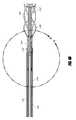
- FIG. 1illustrates one embodiment of a heart pump configured for percutaneous application and operation
- FIG. 1Ais a plan view of one embodiment of a catheter assembly adapted to be used with the heart pump of FIG. 1 ;
- FIG. 2is a detail view of a distal portion of the catheter assembly illustrated in FIG. 1A ;
- FIG. 3is an exploded view of a portion of an impeller assembly of the catheter assembly of FIG. 1A ;
- FIG. 4Ais a cross-sectional view of a distal portion of the catheter assembly, taken through the section plane 4 A- 4 A shown in FIG. 2 ;
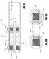
- FIG. 4Bis a detail view of the distal portion of the catheter assembly, taken at 4 B- 4 B shown in FIG. 4A ;
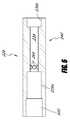
- FIG. 5is a cross-sectional perspective view of a bearing assembly of the catheter assembly of FIG. 1A ;
- FIG. 6is a cross-sectional view of a bearing housing of the bearing assembly of FIG. 5 ;
- FIG. 7is a perspective view of one embodiment of a catheter body that can be used to house a drive shaft and to convey an infusant to the bearing housing of FIG. 5 ;
- FIGS. 7A-7Cshow variations of the catheter body of FIG. 7 ;
- FIG. 8illustrates a surface configuration of one embodiment of a bearing adapted to enhance or control flow of an infusant in the bearing assembly of FIG. 5 ;
- FIG. 9illustrates one embodiment of an impeller assembly
- FIGS. 9A , 9 B- 1 , 9 B- 2 , 10 and 10 Aillustrate details of further embodiments of impeller blade
- FIG. 11is a cross-sectional view of a proximal portion of the catheter assembly, taken through the section plane 11 - 11 on FIG. 1A ;
- FIGS. 12 , 12 A, and 12 Bare cross-section views similar to that of FIG. 11 , illustrating an infusant outflow path;
- FIG. 13-15illustrates various catheter assemblies that provide connection between a distal portion of a catheter body with a proximal portion of an impeller housing
- FIGS. 16-18illustrate another embodiment of a catheter assembly having a simplified construction.
- Section IMajor components of heart pumps that can be applied percutaneously to a patient are described below in Section I.
- Section IIdescribes various structures that facilitate the rotatable support of a cantilevered impeller.
- Section IIIdescribes strategies for minimizing a patient's negative reaction to the presence of the systems within the cardiovascular system.
- Section IVillustrates structures for streamlined catheter assembly connections.
- Section Villustrates methods for use in connection with specific structures of heart pumps
- FIG. 1illustrates one embodiment of a heart pump 10 that includes a catheter assembly 100 having a proximal end 104 adapted to connect to a motor 14 and a distal end 108 (see FIG. 1A ) adapted to be inserted percutaneously into a patient.
- the motor 14is connected by a signal line 18 to a control module 22 that provides power and/or control signals to the motor 14 .
- the heart pump 10may have an infusion system 26 and a patient monitoring system 30 .
- the infusion system 26can provide a number of benefits to the heart pump 10 which are discussed below.
- the infusion system 26includes a source of infusant 34 , a fluid conduit 38 extending from the infusant source 34 to the proximal end 104 of the catheter assembly 100 and a fluid conduit 42 extending from the proximal end of the catheter assembly 100 to a waste container 46 .
- the flow of infusant to and from the catheter assembly 100can be by any means, including a gravity system or one or more pumps.
- the infusant source 34includes an elevated container 50 , which may be saline or another infusant as discussed below. Flow from the elevated container 50 can be regulated by a pressure cuff 54 to elevate the pressure of the fluid in the container 50 to increase flow or by a pinch valve 58 or by other means.
- the patient monitoring system 30can be used to monitor the operation of the patient and/or the pump 10 .
- the patient monitoring system 30can include a user interface 60 coupled with a source of data 64 .
- the data source 64can include one or more patient conditions sensors, such as pressure sensors 68 that are in pressure communication with the patient and/or operating components within the patient.
- the pressure sensors 68fluidly communicate by a conduit 72 that extends between the sensors and a proximal portion of the catheter assembly 100 .
- the conduit 72can include a plurality of separable segments and can include a valve 76 to enable or disable the pressure communication to the sensors 68 .
- the heart pump 10is adapted to provide an acute or other short-term treatment.
- a short-term treatmentcan be for less than a day or up to several days or weeks in some cases. With certain configurations the pump 10 can be used for a month or more.
- the catheter assembly 100extends between the proximal end 104 and the distal end 108 .
- An impeller assembly 116 disposed at the distal end 108is configured to pump blood to convey blood from one body cavity to another.
- the impeller assembly 116conveys blood proximally through or along a portion of the catheter assembly 100 to provide assistance to the left ventricle of the heart.
- the impeller assembly 116conveys blood distally through or along a portion of the catheter assembly 100 to provide assistance to the right ventricle of the heart.
- the heart pump 10is useful as a heart assist device for treating patients with acute heart failure or other heart maladies.
- the heart pump 10also can be used in connection with a surgical treatment to support the patient without providing full cardiovascular bypass. A patient could be supported on the device for longer term with proper controls and design.
- the catheter assembly 100is provided with a low profile configuration for percutaneous insertion.
- the distal end 108 of the catheter assembly 100can be configured to have about an 11 French (approximately 3.5 mm) size in a first configuration for insertion and an expanded configuration, such as up to about 21 French (approximately 7 mm), once positioned in the body.
- the larger sizefacilitates greater flow rates by the impeller assembly 116 as discussed below.
- the catheter assembly 100is configured to enable the distal end 108 to reach a heart chamber after being inserted initially into a peripheral vessel.
- the catheter assembly 100can have a suitable length to reach the left ventricle and sufficient pushability and torquability to traverse the intervening vasculature.
- the catheter assembly 100may include a multilumen catheter body 120 that is arranged to facilitate delivery and operation of the impeller assembly 116 . Further details concerning various embodiments of the catheter body 120 are discussed below in connection with FIGS. 7-7C .
- a drive systemis provided to drive an impeller within the impeller assembly 116 .
- the drive systemincludes a motor 14 and a suitably configured drive controller (not shown).
- the motor 14may be configured to be disposed outside the patient, e.g., adjacent to the proximal end 104 of the catheter assembly 100 .
- the drive systememploys a magnetic drive arrangement.
- the motor 14is arranged to generate magnetic fields that will be sensed by permanent magnets disposed within the proximal end 104 of the catheter assembly 100 . This arrangement facilitates very efficient generation of torque used to drive the impeller assembly 116 , as discussed below.
- Some embodiments described hereincould be incorporated into a system in which a motor is miniaturized sufficiently to be inserted into the patient in use, including into the vasculature. Such an embodiment could be operated by disposing control signal lines within the proximal portion of the catheter body 120 . Also, it may be useful to provide the capability to measure blood pressure at the distal end 108 using a device disposed at the proximal end 104 . For example, a pressure sensor at the distal end can communicate with a device outside the patient through a lumen of the catheter body 120 .
- a pressure sensor at the distal endcan communicate with a device outside the patient through a lumen of the catheter body 120 .
- a mechanical interfacecan be provided between the motor and the proximal end 104 of the catheter assembly 100 .
- the mechanical interfacecan be between the motor 14 and a drive shaft positioned at the proximal end of the catheter assembly 100 .
- a torque coupling systemis provided for transferring torque generated by the drive system to the impeller assembly 116 .
- the torque coupling systemis discussed further in Section II(C)—Torque Coupling System (as discussed below), but in general can include magnetic interface between the motor 14 and a drive assembly 146 disposed at the proximal end 104 of the catheter assembly 100 .
- the drive assembly 146is coupled with a proximal end of an elongate drive shaft 148 in one embodiment.
- the drive shaft 148extends between the drive assembly 146 and the impeller assembly 116 .
- a distal portion of the drive shaft 148is coupled with the impeller assembly 116 as discussed below in connection with one embodiment illustrated in FIGS. 4A and 4B .
- FIG. 11shows one manner of coupling the proximal end of the drive shaft 148 with the drive assembly 146 .
- the heart pump 10may also include an infusion system 26 .
- FIG. 1Ashows that the infusion system 26 can include an infusion inflow assembly 150 provided adjacent to the proximal end 104 in one embodiment.
- the infusion assembly 150can be one component of an infusion system that is configured to convey one or more fluids within the catheter assembly 100 .
- the fluidscan be conveyed distally within the catheter assembly 100 , e.g., within the catheter body 120 , to facilitate operation of the impeller assembly 116 , some aspect of a treatment, or both.
- the infusion systemis configured to convey a lubricant, which, for example, can be saline, glucose, lactated Ringer's solution, acetated Ringer's solution, Hartmann's solution (a.k.a. compound sodium lactate), and D5W dextrose solution.
- a lubricantwhich, for example, can be saline, glucose, lactated Ringer's solution, acetated Ringer's solution, Hartmann's solution (a.k.a. compound sodium lactate), and D5W dextrose solution.
- the infusion systemis configured to convey a medication, or a substance that both acts as lubricant and medication.
- infusantis intended to be a broad term that includes any fluid or other matter that provides performance enhancement of a component of the heart pump 10 or therapeutic benefit, and can be wholly or partly extracted from the system during or after operation of the pump.
- the infusion inflow assembly 150includes a catheter body 154 having a luer or other suitable connector 158 disposed at a proximal end thereof and an inflow port in fluid communication with one or more lumens within the catheter assembly 100 .
- a lumen extending through the catheter body 154is adapted to be fluidly coupled with a fluid source connected to the connector 158 to deliver the fluid into the catheter assembly 100 and through one or more flow paths as discussed below in connection with FIGS. 4A , 4 B, and 7 - 7 B.
- FIGS. 1A and 12show that the catheter assembly 100 may also include an outlet positioned at a location that is outside the patient when the heart pump 10 is in use to allow infusant to be removed from the pump and from the patient during or after the treatment.
- the outletcan be fluidly coupled with an infusant return flow path in the catheter body 120 through a fluid port 144 disposed at the proximal end 104 .
- the catheter assembly 100can also include a sheath assembly 162 configured to constrain the impeller assembly 116 in a low profile configuration in a first state and to permit the impeller assembly 116 to expand to the enlarged configuration in a second state.
- the sheath assembly 162has a proximal end 166 , a distal end 170 , and an elongate body 174 extending therebetween.
- the elongate body 174has a lumen extending between the proximal and distal ends 166 , 170 , the lumen being configured to be slidably disposed over the catheter body 120 .
- the arrangementpermits the sheath assembly 162 to be actuated between an advanced position and a retracted position.
- the retracted positionis one example of a second state enabling the impeller assembly 116 to expand to an enlarged configuration.
- the advanced positionis one example of a first state that enables the impeller assembly 116 to be collapsed to the low profile configuration.
- a luer 102 or other suitable connectoris in fluid communication with the proximal end 166 of the sheath assembly 162 .
- the luer 102can be configured to deliver fluids to the catheter assembly 100 , such as priming fluid, infusant, or any other suitable fluid.
- FIG. 1Aillustrates a retracted position, in which the distal end 170 of the elongate body 174 is at a position proximal of the impeller assembly 116 .
- the distal end 170 of the elongate body 174is positioned distal of at least a portion of the impeller assembly 116 .
- the sheath assembly 162can be configured such that distal advancement of the distal end 170 over the impeller assembly 116 actuates the impeller assembly 116 from an enlarged state to a more compact state (or low profile configuration), e.g., causing a change from the second state to the first state, as discussed above.
- the elongate body 174can include a multilayer construction.
- FIGS. 4A & 4Bshow the elongate body 174 as a single layer structure from the inner surface to the outer surface thereof.
- the elongate body 174has a multilayer construction.
- the elongate body 174has a first layer that is exposed to the catheter body 120 and a second layer exposed that corresponds to an outer surface of the catheter assembly 100 .
- a third layercan be disposed between the first and second layers to reinforce the elongate body 174 , particularly adjacent to the distal end thereof to facilitate collapse of the impeller assembly 116 .
- a reinforcing structurecan be embedded in an otherwise continuous tubular structure forming the elongate body 174 .
- the elongate body 174can be reinforced with a metallic coil.
- FIG. 2show that an impeller housing 202 is disposed at the distal end 108 .
- the impeller housing 202can be considered part of the impeller assembly 116 in that it houses an impeller and provides clearance between the impeller and the anatomy to prevent any harmful interactions therebetween.
- the housing 202 and the impellerare also carefully integrated to maintain an appropriate flow regime, e.g., from distal to proximal or from proximal to distal within the housing.
- FIGS. 1A and 2also show that the distal end 108 of the catheter assembly 100 includes an atraumatic tip 182 disposed distal of the impeller assembly 116 in one embodiment.
- FIG. 1Ashows that the atraumatic tip 182 can have an arcuate configuration such that interactions with the vasculature are minimally traumatic.
- the tip 182can also be configured as a positioning member.
- the tip 182can be flexible and compliant, yet rigid enough to help in positioning the impeller assembly 116 relative to the anatomy.
- the tip 182is rigid enough that when it is urged against a heart structure such as the ventricle wall, a tactile feedback is provided to the clinician indicating that the impeller assembly 182 is properly positioned against the heart structure.
- the impeller assembly 116can take any suitable form, but in various embodiments, includes an impeller 200 adapted to move a fluid such as blood from an inlet to an outlet of the catheter assembly 100 .
- the impeller 200can be cantilevered or otherwise supported for rotation primarily at one end.
- FIG. 3shows that the impeller 200 includes a shaft 204 , a central body or hub 208 , and one or more blades 212 . Particular features of the impeller blades 212 are discussed further below in Section III(A).
- the shaft 204 and hub 208can be joined in any suitable fashion, such as by embedding a distal portion of the shaft within the hub 208 .
- the blades 212can be spaced out proximal to distal along the axis of the shaft. In some embodiments, the blades 212 are provided in blade rows.
- FIG. 9shows that the distal end of the shaft 204 can extend at least to an axial position corresponding to one of the blade rows.
- the shaft 204can be solid.
- the shaft 204has a lumen extending axially through the hub so that a guidewire can be passed through the catheter assembly 100 . Details of variations with a lumen are discussed further in U.S. application Ser. No. 12/829,359, filed Jul. 1, 2010, titled Blood Pump With Expandable Cannula, the contents of which are incorporated by reference herein in their entirety and for all purposes.
- the operation and duty cycle of the impeller assembly 116can be lengthened by providing a hydrodynamic bearing for supporting the shaft 204 .
- a hydrodynamic bearingcan be supported by a lubricant, such as isotonic saline, which can be delivered in a continuous flow.
- the lubricantcan be delivered through the infusion system to an outside surface of the shaft 204 .
- the infusantmay be directed onto the shaft from a radially outward location.
- the lubricant flowis controlled such that of a total lubricant volume introduced into the proximal end of the cannula, a first portion of the total volume of the lubricant flows proximally along the shaft 204 .
- a second portion of the total volumeflows distally along the shaft, the first volume being different from the second volume.
- the second portion of the total volumecan be substantially equal to the total volume introduced into the proximal end of the cannula less the first volume.
- infusantcan be introduced that flows both in an axial and radial direction, for example, from proximal to distal, and radially outward. A small portion of the total infusant introduced can escape from the impeller assembly but most of the total infusant flows from distal back to a proximal direction.
- FIGS. 3 to 8show various structures for providing rotational support of a proximal portion of the shaft 204 within the distal portion of the catheter assembly 100 .
- a bearing assembly 220can be disposed at a distal end 224 of the multilumen catheter body 120 .
- the bearing assembly 224includes a housing 228 (as shown in FIG. 4B ) and one or more bearings configured to support the proximal portion of the shaft 204 .
- the bearing assembly 224includes a plurality of bearings 232 a , 232 b disposed within the bearing housing 228 .
- the bearing housing 228can include a single bearing 232 a .
- Various materials that can be used for the bearingare discussed below.
- FIG. 6shows that the bearing housing 228 has a lumen 234 extending therethrough with a proximal enlarged portion 236 a and a distal enlarged portion 236 b .
- the housing 228comprises a shoulder defining a narrow portion 240 of the lumen 234 disposed between the enlarged portions 236 a , 236 b .
- the first and second bearings 232 a , 232 bcan be disposed within the enlarged portions 236 a , 236 b of the bearing housing 228 .
- the proximal end of the shaft 204(e.g., as shown in FIG. 4A ) is received in and extends proximally of the second bearing 232 b .
- there can be one bearinge.g., only bearing 232 a
- both bearings 232 a and 232 bcan be used.
- the bearing(s), e.g., bearings 232 a and/or 232 bcan be friction fit or interference fit onto the impeller shaft 204 .
- the shaft 204can be supported for rotation by the bearings 232 a , 232 b as well as in the narrow portion 240 of the housing 228 .
- the bearing(s) 232 a , 232 bcan be configured to rotate with the shaft 204 relative to the bearing housing 228 . Further, the bearing(s) 232 a , 232 b can have a relatively large clearance with the bearing housing 228 .
- the clearance between the shaft 204 and the bearing housing 228 , at regions that are not coupled with the bearing,can be in the range of about 0.0005 to about 0.001 inch. In certain embodiments, the clearance can be within a larger range, such as at least about 0.0005 inches, about 0.001 inches or up to about 0.005 inches.
- the clearancecan be different for the bearings 232 a , 232 b , such as providing a larger clearance at the proximal bearing 232 a.
- the bearing(s) 232 a , 232 bmay not be friction or interference fit onto the shaft 204 .
- the bearing(s) 232 a , 232 bmay be disposed within the bearing housing 228 , for example by an interference or press fit.
- the shaft 204may then rotate with respect to the bearing(s) 232 a , 232 b , and there can be a clearance between the shaft 204 and the bearing(s) 232 a , 232 b .
- the clearance between the shaft 204 and the bearings 232 a , 232 bcan be in the range of about 0.0005 to about 0.001 inch.
- the clearancecan be within a larger range, such as at least about 0.0005 inches, about 0.001 inches or up to about 0.005 inches.
- the clearancecan be different for the bearings 232 a , 232 b , such as providing a larger clearance at the proximal bearing 232 a .
- the bearing housing 228may provide a thrust surface for bearing axial loads.
- the fit between the bearings 232 a , 232 b and the shaft 204can be tight, which can also assist in bearing axial loads in some aspects.
- At least the proximal portion of the shaft 204can be made of a material that will not corrode or otherwise be made to be inert when immersed in the lubricant or other infusant.
- the materialmay be one that will not corrode in isotonic saline. Suitable materials may include a wide variety of metals, including alloys, and at least saline-resistant stainless steel and nickel-based alloys.
- the shaft 204could be made as a composite to include advantageous properties of a plurality of materials. In some cases the shaft 204 could be formed as a polymer.
- the class of polymers selectedwould include those that can form a shaft 204 of a certain stiffness suitable in this application.
- polycarbonate or PEEKcould be used. In certain configurations, the polycarbonate, PEEK, or other suitable polymer can provide enhanced performance by being combined with a second material or structure. A glass or carbon filled polycarbonate or other stiff polymer could also be used.
- a hydrodynamic bearing between the shaft 204 and the bearings 232 a , 232 bmay be utilized in various embodiments.
- a continuously replenished fluid filmis provided at least between the inner wall of the bearing housing and an adjacent moving structure, such as the impeller shaft or an outer surface of a bearing.
- the bearing housing 228can be configured to permit a lubricant to be delivered therethrough into the lumen 234 .
- the bearing housing 232can include a plurality of channels 260 disposed therein extending proximally from a plurality of ports 264 located at the narrow portion 240 of the housing 228 . Each port 264 can communicate with one of the channels 260 to provide fluid communication into the lumen 234 .
- the channels 260can be formed in the wall of the housing 228 .
- the channels 260are formed as open depressions, e.g., as flutes, extending along the housing 228 .
- the channels 260can be enclosed by a separate structure, such as a separate outer sleeve, that is disposed around the housing 228 .
- FIG. 4Bshows that a proximal portion 268 of the impeller housing 202 can be sized to tightly fit over the outer surface of the bearing housing 228 , enclosing the radially outward portion of the channels 260 .
- at least a portion of a flow pathis formed between an outer surface of the bearing housing 228 and a separate outer sleeve.
- Fluid communication between the port 264 in the bearing housing 228 and the infusion inflow assembly 150can be by any suitable combination of lumens within the catheter assembly 100 .
- each of the channels 260has a proximal port 272 that communications with an annular space 274 formed in the catheter assembly 100 .
- the annular space 274can be formed between a plurality of separate overlaid structures in the catheter assembly 100 .
- FIGS. 4A and 4Bshow that the annular space 274 is formed between an outer surface 278 of the multilumen catheter body 120 and an inner surface of the proximal length 268 of the housing 202 .
- Fluid communicationis provided in the catheter assembly 100 between the space 274 and the infusion inflow assembly 150 .
- one or a plurality of lumens 282 formed in the multi-lumen catheter body 120can be dispersed circumferentially about the catheter body 120 at a peripheral circumferential region 284 , as illustrated in FIGS. 7-7C .
- the peripheral position of the lumens 282enables a central area of the catheter body 120 to be dedicated to a central lumen 286 .
- a relatively large flow ratecan be delivered through a relatively small circumferential band (when considered in cross-section) of the catheter body 120 .
- Each of the lumen 282has a distal port 290 that communicates with the space 274 .
- a proximal portion of the lumens 282can take any suitable form.
- the lumens 282can communicate at their proximal end with a flow diverting structure (not shown) that is in fluid communication with the infusion inflow assembly 150 .
- the lumen 282can be disposed circumferentially about the central lumen 286 .
- the catheter assembly 100can include a flow diverting structure or connector, e.g., disposed about the proximal end of the catheter body 120 that is configured to divert the infusant into the lumens 282 for distally directed flow therein.
- the catheter assembly 120can include a flow diverting structure disposed adjacent the distal end thereof that is configured to divert the infusant into the lumens 282 from the central lumen 286 for proximally directed flow in the lumens 282 .
- FIG. 5includes arrows that illustrate the flow of infusant into the bearing assembly 220 .
- the inflow of infusantis indicated by an arrow 300 which is shown pointing distally within one of the channels 260 of the bearing housing 228 .
- the infusant flowenters the bearing housing through the ports 264 .
- flowis shown in one channel 260 , corresponding flow may be provided in each of a plurality of channels 260 disposed around the central lumen 234 .
- An arrow 304illustrates that at least a portion of the infusant delivered through the port 264 flows generally proximally within the bearing housing 228 in various embodiments.
- An arrow 308illustrates that at least a portion of the infusant delivered through the port 264 flows generally distally within the bearing housing 228 in some embodiments.
- FIG. 5illustrates the arrows 304 , 308 as proximally and distally directed, respectively.
- the high speed rotation of the impeller shaft 204 within the housing 228will create a thin film of lubricant spacing the impeller shaft 204 from the surfaces of the bearings 232 a , 232 b .
- This thin filmwill extend all the way around the shaft 204 and thus each portion of the flow will have a spiral or helical flow direction.
- the bearings 232 a , 232 bcan have different configurations to enhance the performance of the pump 10 .
- the proximal bearing 232 acan be longer along the longitudinal axis of the bearing housing 228 than the distal bearing 232 b .
- a longer proximal bearing 232 ais believed to better control runout of the shaft 204 .
- Better runout control on the shaft 204is believed to enhance the control of the position of the blades 212 relative to the housing 202 .
- Less runoutreduces excessive variation in the gap between the blades 212 and the housing 202 , providing biocompatibility benefits such as reduced hemolysis.
- the distal bearing 232 bhas a smaller inner diameter than the proximal bearing 232 a . If the shaft 204 has a constant diameter, the smaller inner diameter should provide greater control of angular deflection of the shaft. Controlling angular deflection can enhance relative position control of the blades 212 and housing 202 , providing blood handling benefits such as reduced hemolysis. A smaller clearance could also be provided by enlarging the diameter of the shaft 204 at the axial position of the distal bearing. In some embodiments, the larger inner diameter of the bearing 232 b enables a larger volume of lubricant to flow proximally and a lesser volume to flow distally in the lumen 234 .
- the continuous introduction of lubricantmaintains a constant, predictable and durable rotational bearing state between stationary component, e.g., the bearing housing 282 , and a moving component, e.g., the shaft 204 , a component of the bearings 232 a , 232 b , or both the shaft 204 and a component of the bearings 232 a , 232 b .
- continuous lubricant inflowprovides a means for removing heat generated by the relative motion between the shaft 204 and the bearings.
- the infusantcan create fluid pressure within the catheter assembly 100 that can push debris generated within or by the pump 10 out of the bearing housing 220 . Enhancing the volume of infusant that flows along the path indicated by the arrow 304 enhances the likelihood that debris generated by or present in the pump will be removed from the proximal end rather than to be trapped inside the distal portion of the catheter assembly 100 .
- Another technique for controlling infusant flow in the lumen 234is to locate the port 264 between the bearings 232 a , 232 b and closer to one of the bearing.
- the ports 264can be located adjacent to the proximal bearing 232 a in one embodiment. This provides a shorter path of egress out of the narrow portion 240 of the bearing housing 228 in the proximal direction.
- FIG. 8shows a surface modification 233 provided in a bearing 232 a to enhance proximally directed flow.
- the surface modification 233comprises a plurality of axially oriented grooves 235 in one embodiment.
- the surface modification 233includes one or more spiral grooves.
- the spiral groovescan be formed with a groove entrance that is substantially parallel with a flow direction of infusant between the bearings 232 a , 232 b such that a reduction of velocity of the flow is minimized.
- each spiral grooveincludes at least about 3 turns disposed on the inner surface of the bearing between the proximal and distal ends of the bearing. In another embodiment, each spiral groove has adjacent turns that are spaced apart by a minimum pitch of 0.125 inches (3.2 mm). In another embodiment, each spiral groove has an axial density of about 32 turns per inch (about 1.3 turns per mm).
- the groovesare formed in the surface 237 of the bearing 232 a upon which the impeller shaft 204 is supported. The grooves 235 locally enlarge the clearance between the shaft 204 and the surface 237 so that a greater volume of infusant can flow distal-to-proximal across the bearing 232 a .
- the surface modification 233reduces back-pressure limiting the distal-to-proximal flow across the bearing 232 a.
- the infusantmay be provided with a fluid intended to be delivered to the patient.
- the surface modification 233can be provided on the distal bearing 232 b .
- both proximal and distal bearings 232 a , 232 bare provided with flow enhancing modifications to enhance heat transfer or purging of the bearing assembly 220 .
- one of the bearingsmay have a greater degree of flow enhancement provided on the bearing surface.
- the arrangement of the bearing assembly 220can be a factor in selecting an appropriate infusant.
- Salineis one type of infusant, but other sufficiently biocompatible infusants could be used.
- Other embodimentsare configured such that little or no infusant flows out of the pump into the patient.
- other infusant fluidscan be used, such as glucose.
- FIG. 7illustrates further features of the catheter body 120 .
- the catheter body 120comprises an inner most portion 320 that defines the central lumen 286 .
- the inner most portion 320is disposed within, e.g., circumferentially surrounded by, the peripheral circumferential region 284 .
- a continuous outer circumferential region 324can be provided around the peripheral circumferential region 284 to fully enclose the lumen(s) 282 , discussed above.
- FIGS. 4A and 4Billustrate that a distal end of the inner most portion 320 is configured to be received and secured within a proximal portion of the lumen 234 within the bearing housing 228 .
- FIG. 4Billustrates that a region of overlap can be provided between a distal portion of the inner most portion 320 and a proximal portion of the bearing housing 228 .
- This constructionprovides a continuous lumen defined in part by the central lumen 286 of the catheter body 120 and in part by the lumen 234 of the bearing housing. Another arrangement is discussed below in connection with FIG.
- this continuous lumenalso referred to as a drive lumen, can be configured to receive at least a portion of the drive shaft 148 and/or the shaft 204 and provides a space for the rotation of the shaft 204 of the impeller assembly 116 and the drive shaft 148 of the torque coupling system.
- FIG. 3illustrates that in one arrangement, a slideable connection is provided.
- a rod 332is provided between the bearing housing 228 and the catheter body 120 .
- the rod 332can have any suitable configuration, but in some embodiments, the rod 332 has a proximal end configured to be received in a recess or lumen formed in the catheter body 120 and a distal end 340 configured to couple with the bearing housing 228 .
- FIG. 3shows that the distal end 340 of the rod 332 can be configured to engage with a feature of the bearing housing 228 so that a limited range of sliding is permitted.
- the bearing housing 228has an elongate channel 342 configured to receive a middle portion of the rod 332 and an enlarged depression 344 located at the distal end of the channel 342 .
- the depression 344has a width W that is sufficient to receive a wide distal end of the rod 332 .
- the depression 344can be configured to have an axial length along the housing 228 that can define a range of motion of the bearing housing 228 relative to the catheter body 120 .
- the bearing housing 228is positioned relative to the catheter body 120 and the rod 332 such that the distal portion of the rod 332 is located at the distal end of the depression 344 . Thereafter, the catheter assembly 100 can be manipulated such that the bearing housing 228 moves distally relative to the catheter body 120 and the rod 332 such that the distal portion of the rod 332 is located at the proximal end of the depression 344 . In the distal position, the impeller assembly 116 is located more distally than in the proximal position. As discussed further below, this enables a variety of techniques for unfurling the impeller blades 212 within the housing 202 .
- Any suitable bearingcan be used in the catheter assembly 100 .
- the provision of an infusant for hydrodynamic supportenables a wide range of bearing materials to be used. If saline or other more corrosive infusant is used, the bearing must be carefully configured to not degrade within the expected duty cycle of the pump 10 . Some polymeric materials are advantageously not degraded by isotonic saline, and are acceptable materials from this perspective.
- a hydrodynamic bearing that is supported by a biocompatible infusant such as isotonic salineis used in various embodiments. It is believed that certain polymer bearings in combination with isotonic saline can support such conditions as 35,000-50,000 psi-ft/min for an appropriate duty cycle.
- a substantially non-swellable materiale.g., a material that absorbs little or no water
- the use of a non-swellable materialcan prevent distortion of the bearing, e.g., due to continued exposure to an aqueous environment.
- non-swellable materialsinclude some high molecular weight polymers (e.g., having a molecular weight greater than 10,000 Daltons).
- the polymeric materialcan include a homopolymer, a copolymer, or a mixture of polymers.
- the polymeric materialcan include thermoplastic or thermoset polymers. Examples of polymers that can be used for bearings 232 a , 232 b include, but are not limited to, one or more of a polyketone, a polyether, a polyacetal, a polyamide-imide, a polyacetal, polyether ether ketone (PEEK), polytetrafluoroethylene (PTFE), and polyphenylene sulfide (PPS).
- at least one bearingis a PEEK bearing.
- the polymeric materialcan also include (e.g., can be mixed, combined, and/or filled with) one or more additives such as a reinforcer and a lubricant.
- additivesinclude, but are not limited to, graphite, carbon fiber, glass fiber, and PTFE.
- the additivesmay be polymeric or non-polymeric.
- the polymeric material used for bearings 232 a and/or 232 bcan include PEEK, carbon fiber, PTFE, and graphite.
- the polymeric materialcan include PPS and glass fiber.
- the polymeric materialcan include a polyamide-imide polymer, carbon fiber, and graphite.
- the polymeric materialcan include any suitable amount of additive(s).
- the polymeric materialcan include a total amount of additive(s) in the range of from about 1 wt % to about 50 wt %, based on the total weight of the polymeric material.
- the polymeric material used for bearings 232 a , 232 bmay not include any additives.
- the polymeric material chosen for bearings 232 a , 232 bcan have particular characteristics that advantageously affect the performance of the bearings.
- a preferred materialwould be subject to a minimum of dimensional change, and can have a coefficient of thermal expansion in the range of from about 1.2 ⁇ 10 ⁇ 5 ° F. ⁇ 1 to about 25.2 ⁇ 10 ⁇ 5 ° F. ⁇ 1 .
- the polymer used for bearings 232 a , 232 bhas a coefficient of friction in the range of from about 0.15 to about 0.3.
- the selected polymeric materialin order to minimize or prevent water absorption, can have a water adsorption in the range of from about 0.01% to about 0.4% over a 24 hour period.
- the polymeric materialcan be suitable for high pressure and velocity performance, and can have a limiting pressure-velocity (PV) in the range of from about 20,000 psi-ft/min to about 50,000 psi-ft/min.
- the polymeric material used for bearings 232 a , 232 bmay be commercially available.
- suitable, commercially-available polymeric materialsinclude, but are not limited to, Ketron PEEK-HPV, Turcite A, Turcite X, Turcite TX, Rulon LR, Rulon J, Rulon 641, Rulon AR, Techtron HPV PPS, Ryton PPS, Torlon 4301, and Torlon 4501.
- the polymeric material used for bearings 232 a , 232 bis Ketron PEEK-HPV.
- bearing configurations and/or materialswould be suitable under other conditions, e.g., with less corrosive infusants or if a hydrostatic or non-hydraulic bearing is used.
- the bearing 232 acan be friction fit, interference fit, or press fit onto the shaft 204 , such that the bearing 232 a is configured to rotate with the shaft 204 relative to the bearing housing 220 (e.g., there can be little or no clearance between the bearing 232 a and the shaft 204 ).
- Support for the shaft 204can be provided by the bearing 232 a and the bearing housing 220 .
- the clearancecan be within a larger range, such as at least about 0.0005 inches, about 0.001 inches or up to about 0.005 inches.
- the lumen 234 extending through the housing 228can be substantially constant distal of the bearing 232 a , e.g., sized to have proper clearance to the shaft 204 along that length.
- the distal enlarged portion 236 bis eliminated. This configuration is simpler to manufacture and may be less costly.
- the bearing 232 acan be configured as a thrust bearing to bear axial loads.
- the bearing 232 acan advantageously minimize the distal and/or proximal movement of the impeller 200 (e.g., impeller shaft 204 ), drive assembly 146 , drive shaft 148 , and/or elongate body 408 relative to the impeller housing 202 .
- the bearing 232 acan be configured as a fluid journal bearing, wherein the infusant creates a hydrodynamic layer that can transfer heat during operation and reduce friction between the inner surface or wall of the bearing housing 228 and the outer surface of the bearing 232 a .
- the proximal portion of the bearing housing 228can also advantageously be configured as a fluid journal bearing, wherein the infusant creates a hydrodynamic layer that can transfer heat during operation and reduce friction between the inner surface or wall of the bearing housing 228 and the outer surface of the impeller shaft 204 .
- a torque coupling systemis provided to rotate the impeller 200 at a high rate to move blood from inside a heart camber to a location within a patient's vasculature in amounts sufficient to sustain the patient or provide treatment to the patient.
- the torque coupling systemcouples the impeller 200 with the motor 14 , which may be disposed outside the patient. It is expected that the impeller 200 and the drive shaft 148 are to be rotated at 25,000-30,000 revolutions per minute for a period of seven to ten days. To provide reliable performance under these conditions, isotonic saline or other lubricant is provided between the drive shaft 148 and stationary components therearound.
- FIGS. 11 and 4Billustrate proximal and distal portions 400 , 404 of the drive shaft 148 .
- the proximal portion 400is coupled with the drive assembly 146 such that rotation of the drive assembly 146 rotates the drive shaft 148 .
- the distal portion 404 of drive shaft 148is coupled with the impeller shaft 204 such that rotation of the drive shaft 148 causes rotation of the impeller shaft 204 .
- the drive shaft 148also includes an elongate body 408 that extends between the proximal and distal portions 400 , 404 .
- the elongate portion 408comprises a lumen 412 extending therethrough.
- the size of the elongate body 408may be as small as possible to minimize the cross-sectional profile of the catheter assembly 100 .
- the cross-sectional profile of the catheter assembly 100corresponds to the crossing profile of the catheter assembly, which limits where the system can be inserted into the vasculature.
- the lumen 412is sized to permit a guidewire to be advanced therethrough in some embodiments. The use of a guidewire is optional, but may simplify insertion.
- the elongate body 408comprises a multi-layer construction.
- each layercan include at least one coil wire or a plurality of coil wires all wound in a same orientation.
- a first layer (e.g., an inner layer) of the elongate body 408is provided by a coiled wire of nickel-molybdenum-chromium alloy, such as 35NLT or MP35N.
- the wire materialcan be MP35N LT.
- the wirehas a 0.008 inch diameter and the coil has a 5 filar right-hand wound construction.
- the outer diameter of the first layermay be about 0.071 inch.
- a second layer (e.g., an outer layer) of the elongate body 408can include the same material as the first layer, disposed on the outside of the first layer.
- the first and second layerscan be wound in the same direction, or in opposite directions.
- the first layere.g., an inner layer
- the second layere.g., an outer layer
- both the first and second layerscan be left-hand wound.
- both the first and second layerscan be right-hand wound.
- the wound coil wire constructioncan advantageously facilitate proximal and/or distal flow of infusant along the outer layer of the elongate body 408 .
- the outer layercan be constructed such that the infusant travels along the coil and/or in the direction of the winding.
- the second layermay be a 5 filar left-hand wound construction.
- each layeris formed using a 0.008 inch diameter wire, in the above-noted coiled configuration.
- the elongate body 408can include three or more coil wire layers, wherein the layers are wound in alternating directions.
- the outer diameter of the second layercan be between about 0.072 inch and about 0.074 inch, while in other embodiments the diameter can be much larger or smaller. In some aspects, for example, the outer diameter of the second layer can be about 0.073 inch.
- the inner diameter of the elongate body 408can be at least about 0.039 inch in some implementations. In some embodiments, one or more ends of the elongate body 408 can be welded and square cut, for example, with a 0.1 inch maximum weld length on each end. The length of the elongate body 408 can vary, but in some embodiments, the length can be between about 47 inches and 48 inches, for example, about 47.5 inches.
- the elongate body 408can be made of other non-ferrous metals or other corrosion resistant material or constructions with appropriate modulus. Other materials that could meet the corrosion requirements include stainless steel (e.g., 302, 304, or 316). In certain embodiments, the elongate body 408 can have a structure that enables other materials to be used. For example varying at least one of coil layers, filars, wire diameter, and coil diameter may enable an otherwise less robust material to operate below the fatigue stress of that material.
- a four layer constructionis provided.
- the four layerscomprise three wire-wound layers, e.g., similar to the arrangement described above, but included a third wound layer on the outer surface of the second layer.
- a low friction layercan be disposed on the outside surface of the elongate body 408 .
- One material that could be used as a low-friction layeris PTFE, known commercially as Teflon®.
- the low-friction layershould be configured to have sufficient wear resistance, such as by selection of the appropriate PTFE material, e.g. polyphenylene sulphone-filled PTFE, and/or by insuring appropriate infusant flow is maintained during the entire duration of use of the device in order to prevent undesirable local elevated temperature of the PTFE material.
- the drive shaft 148operates within the multilumen catheter body 120 . Because the drive shaft 148 is rotated at a very high rate when in use within the multilumen catheter body 120 , the configuration of the surface forming the central lumen 286 is important. In various embodiments, this inner surface may have high lubricity and high wear resistance.
- One material that can be used for the inner surface of the catheter body 120is high density polyethylene (HDPE), which provides sufficient lubricity and wear resistance.
- the entire multilumen catheter body 120is foamed of HDPE. PTFE provides good lubricity and could be used if made sufficiently wear resistant.
- PTFEpolyphenylene sulphone
- FIG. 4Bshows a clearance 412 between the elongate body 408 of the drive shaft 148 and the inner surface of the multilumen catheter body 120 .
- the clearance 412may be at least about 0.005 inch.
- the clearance 412may be at least about 0.005 inch.
- Along a diameter between opposite sides of the inner surface of the central lumen 286 and outer surface of the elongate body 408includes about 0.010 inch of space or diametric clearance.
- a larger minimum clearancemay be desirable if the crossing profile can be enlarged or if other structures of the catheter assembly 100 can be made thinner or eliminated to allow more room between the elongate body 408 and the central lumen 286 .
- FIGS. 11 and 12show further details of the drive assembly 146 , which is disposed at the proximal end 104 of the catheter assembly 100 .
- the drive assembly 146includes a drive housing 450 having a recess or cavity 454 disposed therein.
- the cavity 454is configured for mounting a rotor support shaft 458 for rotation therein.
- the support shaft 458has a proximal end and a distal end and a plurality of components mounted thereon.
- the distal end of the support shaft 458has a recess 462 formed therein to receive a proximal end of the drive shaft 148 .
- the support shaft 458may also have a lumen 466 disposed therein for slideably receiving a guidewire.
- a rotor 470is mounted on an outer surface of the support shaft 458 between sleeve bearings 474 a , 474 b , as shown in FIG. 12 .
- the rotor 470can take any suitable form, but in one embodiment includes an elongate magnet 476 disposed between proximal and distal flywheels 478 a , 478 b.
- the proximal end of the support shaft 458has a tapered port 480 for receiving the guidewire.
- the proximal endcan be configured for engaging the motor 14 in some embodiments. In other embodiments, a magnetic field is induced by the motor 14 in a manner that creates torque and rotation of the shaft 458 .
- An infusant outflow path 482is provided within the drive assembly 146 .
- the outflow path 482is provided between an outer surface of the support shaft 458 and an inner surface 486 of the distal bearing.
- the flow path 482continues from the distal bearing 474 b radially outwardly along thrust surface 490 b .
- the flow pathcontinues proximally between the outer surface of the rotor 470 and the inner surface defining the cavity 454 .
- the flow path 482continues radially inwardly along the thrust surface 490 a toward the support shaft 458 .
- the flow path 482continues proximally between the support shaft 458 and the proximal bearing 474 a .
- the flow of infusantexits the catheter assembly 100 through an outflow port 144 through which it can be directed to the waste container 46 or discarded.
- the flow pathis shown in more detail in FIGS. 1 , 12 , 12 A, and 12 B.
- the heart pump 10includes various features that enhance the biocompatibility of the pump.
- the impeller 200 and the housing 202are carefully configured to interact with the blood in a way that minimizes hemolysis.
- the blood contacting surfaces and components of the heart pump 10can be enhanced to minimize adverse effects within the patient.
- the impeller 200may be configured to minimize blood hemolysis when in use, while at the same time providing sufficient flow generating performance.
- FIG. 9illustrates some configurations in which the work performed by the impeller blades 212 , as defined by the flow-pressure performance, is maximized.
- the proximal and distal impeller bladeshave tips 212 a that can have a generally flat configuration.
- the flat aspect of the distal tips 212 acan be disposed at the outermost end thereof.
- the tips 212 acan have an arcuate shape about the hub 208 . More particularly, the arcuate shape can be a helical shape as shown in FIG. 9 .
- the flat end portion of the tips 212 aprovides a surface that is generally parallel to the inner wall of the impeller housing 202 . In testing, the flat tips 212 a have exhibited optimal hydrodynamic performance.
- the number of blades 212 on the impeller 200can vary.
- the impeller 200can have one, two, three, four, five, six, or more total blades 212 .
- the impeller 200can have four total blades 212 .
- the impeller 200can have two total blades 212 .
- the axial orientation of the blade(s) 212can vary.
- the blades 212can be arranged axially along the impeller hub 208 in one, two, three, or more rows. As illustrated in FIG. 9A , for example, the impeller 200 can include two blade rows, each row including two blades.
- a multiple row arrangementmay be advantageous in that the maximum amount of time blood components contact the blade is less than is the case with a comparable single row blade configuration.
- a two row configurationcan result in less contact time compared to a single row configuration.
- a blade in a single row configurationhas an axial length L 1 .
- the axial distance from the leading edge of the forward blade to the trailing edge of the rearward bladecan also be a length L 1 .
- a gap between the two blades in the two row configurationcan have an axial length of G 1 . When flowing through the gap, the blood is not in contact with the blades. This short segment or gap of no blood contact with the blades breaks-up the contact time, which provides better handling of delicate structures of the blood.
- the impeller 200can have two blades total, the blades being arranged in a single row (e.g., wherein all of the blades are at generally the same axial position along the impeller hub 208 ).
- an impeller 200 with fewer blade rowscan be manufactured more easily than an impeller with a larger number of blades and/or a larger number of rows.
- an impeller 200 with fewer blade rowscan be deployed and/or retrieved more easily than an impeller with additional blade rows. Note that while, in general, FIGS. 9 , 9 A, 9 B- 1 , and 9 B- 2 are representative of certain embodiments of blades and impellers, the disclosed blades may have further features not shown to scale.
- the bladeswrap around the shaft such that the leading edge of each blade is off-set by a substantial amount from the trailing edge of the same blade.
- the leading and trailing edgescan be offset by at least about 10 degrees, in some embodiments up to 40 degrees. In other embodiments, the leading and trailing edges are off-set by up to 90 degrees or more.
- a first bladehad a leading edge at a first circumferential position and a trailing edge at a second circumferential position
- a second bladehas a leading edge at a circumferential position between the circumferential position of the leading edge and trailing edge of the first blade.
- the circumferential orientation of the blade(s) 212 from one row relative to anothercan also vary.
- the blades in the first blade rowe.g., blade 213 a - 1
- the blades in the second blade rowe.g., blade 213 a - 2
- the bladescan be fully clocked (e.g., no circumferential overlap between blades).
- the bladescan be partially clocked (e.g., some circumferential overlap between blades).
- the blades in the first blade rowcan be aligned with the blades in the second blade row (e.g., blade 214 a - 2 ), for example as illustrated in FIG. 9B-2 .
- the clocked bladescan have many advantages, such as increased flow rate, reduced friction, and/or increased ease of deployment/retrieval.
- FIG. 10illustrates another embodiment of an impeller blade 212 ′ that includes modified tips 212 b .
- the distal tips 212 bare rounded on suction to pressure side of the blade.
- the rounding of the tips 212 bcan result from eliminating one or more edges between the suction side surface and the pressure side surface.
- some embodimentsprovide a plurality of sharp edges between the leading edge, trailing edge, and end surface of the blades. By eliminating one or more of these sharp edges a rounded profile is provided.
- this roundingreduces fluid stress and fluid stress gradient (change in pressure and/or in strain rate per unit length of the fluid flow path) on the constituents of the fluid being pumped.
- the reduction of such stresses and gradientcan provide a more biocompatible interaction of the pump 10 with blood when used as a blood pump.
- red blood cellscan be damaged by being subject to high stresses or to high stress gradients. By reducing exposure of red blood cells to these conditions, hemolysis can be reduced.
- the configuration of the blades 212 ′provides the further advantage of reducing sensitivity to the gap between the tip 212 b and the inner wall of the housing 202 . Where sharp edge configurations are provided, variations in the gap between the tip and the housing wall can greatly affect the flow performance of the pump 10 . However, by rounding the edges as in the blades 212 ′, the variation of flow performance is much less due to changing tip gap. Because the housing 202 is flexible and the distal portion of the catheter assembly 100 is disposed in a highly dynamic environment during use this arrangement reduces perturbations in the flow characteristics within the housing 202 , providing an even more robust design.
- a further advantage of the rounded tip designis that the lessened sensitivity to tip gap provides a better configuration for manufacturing. This arrangement permits wider manufacturing tolerances for one or both of the impeller 200 and the impeller housing 202 .
- FIG. 10Aillustrates further variations of the rounded tip design that combine one or more rounded edges with a flat area 212 c at or adjacent the tip of the blade 212 ′′.
- Rounded edgesextend from one end of the flat area toward the leading edge of the blade 212 ′′ and from another end of the flat area 212 c toward the trailing edge of the blade 212 ′′.
- the flat area 212 Ccan be combined with a single rounded edge that extends only toward the leading edge or only toward the trailing edge.
- One advantage of the combination of the flat area 212 c with one or more rounded edgesis that this combination maximizes hydrodynamic performance that would occur with a “square edged” tip while providing the benefit of a more gradual change in fluid pressure and fluid stresses resulting in better hemolytic performance that would occur with a rounded tip shape.
- FIG. 9Aillustrates another embodiment of an impeller blade 213 a that includes modified tips 213 b .
- the tips 213 bare rounded on the leading edge and trailing edge of the blade. By eliminating sharp edges a rounded profile is provided in the axial direction. Rounding in this fashion provides the same general benefits as the “cross-blade” tip rounding in 212 b , 212 c . Without being bound to any particular theory, it is believed that this rounding reduces fluid stress and fluid stress gradients on the constituents of the fluid being pumped. The reduction of such stresses and gradient can provide a more biocompatible interaction of the pump 10 with blood when used as a blood pump. For example, red blood cells can be damaged by being subject to high stresses or to high stress gradients. By reducing exposure of red blood cells to these conditions, hemolysis can be reduced.
- the impeller 200can include an outer coating layer (not shown).
- the outer coating layercan include one or more polymers.
- the one or more polymerscan include a homopolymer, a copolymer, and/or a mixture of polymers.
- the one or more polymerscan be linear, branched, or crosslinked.
- the one or more polymerscan be thermoset or thermoplastic.
- the one or more polymersare elastomeric.
- the outer coating layercan be hydrophilic.
- suitable polymersinclude, but are not limited to, silicones (e.g., a siloxane), silanes (e.g., an alkyltriacetoxysilane), polyurethanes, acrylics, and fluoropolymers.
- siliconese.g., a siloxane
- silanese.g., an alkyltriacetoxysilane
- polyurethanesacrylics
- acrylicsand fluoropolymers.
- siloxane polymerthat has been substituted with one or more alkyl, alkoxy, and/or poly(alkyl amine) groups.
- Polymers suitable for the outer coating layercan be commercially available and/or synthesized according to methods known to those skilled in the art. Examples of commercially available polymers include the Dow Corning MDX line of silicone polymers (e.g., MDX4-4159, MDX4-4210).
- the outer coating layercan also include a therapeutic agent, e.g., a drug that limits the ability of thrombus to adhere to the impeller 200 .
- a therapeutic agente.g., a drug that limits the ability of thrombus to adhere to the impeller 200 .
- a suitable therapeutic agentis heparin.
- the impeller 200can include two or more coating layers.
- a substantial portion of the entire exposed surface of the impeller 200is coated with an outer coating layer. In other embodiments, only a portion of the exposed surface of the impeller 200 is coated with an outer coating layer. For example, in some embodiments, one or more impeller blades 212 , or portions thereof, are coated with an outer coating layer.
- the impeller housing 202can include an outer coating layer (not shown). Suitable materials for the outer coating layer of the impeller housing 202 include, but are not limited to, those described herein with respect to the outer coating layer of the impeller 200 . In some embodiments, the impeller housing 202 can include two or more coating layers.
- a substantial portion of the entire exposed surface of the impeller housing 202is coated with an outer coating layer. In other embodiments, only a portion of the exposed surface of the impeller housing 202 is coated with an outer coating layer.
- the outer coating layercan coat the impeller housing 202 but not the openings. In other embodiments, the outer coating layer can coat the impeller housing 202 and one or more openings, resulting in a substantially closed impeller housing 202 .
- the outer coating layercan be applied to the impeller 200 and/or impeller housing 202 by methods known to those skilled in the art, such as dip, spray, or flow coating.
- the outer coating layercan impart one or more advantageous properties to the impeller 200 and/or impeller housing 202 .
- an impeller 200 that includes an outer coating layercan exhibit reduced thrombosis, reduced hemolysis, increased lubricity, and/or reduced friction as compared to an otherwise similar impeller that lacks an outer coating layer.
- application of an outer coating layer to the impeller 200can reduce surface friction, which can improve hemolysis performance by reducing drag forces between the blood and the impeller blades.
- the outer coating layercan assist in the process of deployment and/or retraction by reducing the coefficient of friction between the collapsed or partially collapsed sliding components.
- FIG. 13shows another embodiment of a catheter assembly 500 that includes an elongate catheter body 524 and a proximal portion 540 of an impeller housing that provides for enhanced securement of the connection therebetween.
- the elongate body 524comprises a central lumen 528 in which a drive shaft operates and a plurality of peripheral lumens 532 through which infusant can be delivered, as discussed above.
- the impeller housingcan be similar to the impeller housing 202 and the elongate body 524 can be similar to the catheter body 120 in many respects, which will not be repeated here.
- FIG. 13shows that adjacent the distal end of the catheter assembly, there is a length over which a distal portion of the elongate body 524 and the proximal portion 540 of the impeller housing, also referred to as a hypotube, are joined.
- the distal portion of the elongate body 524can have an outer diameter that is smaller than the inner diameter of the proximal portion 540 of the impeller housing, allowing the elongate body 524 to extend within the proximal portion 540 of the impeller housing.
- An outside surface of the elongate body 524contacts an inner surface of the proximal portion 540 .
- the proximal portion 540 of the impeller housingcan have a generally cylindrical shape, and can generally be non-expandable.
- the configuration of the surface forming the lumen 528is important. In some embodiments, this surface has high lubricity and high wear resistance. High density polyethylene (HDPE) can be used to form the lumen 528 .
- HDPEHigh density polyethylene
- the bond between the twois very important because if the bond breaks when removing the catheter assembly 500 from the patient's heart, the proximal portion 540 of the impeller housing could be dislodged and left in the patient.
- the highly lubricious nature of the elongate body 524can make securement of these components more difficult.
- the distal portion of the elongate body 520 and the proximal portion 540can be connected using an adhesive bond such as glue. However, it may be desirable to replace or supplement such a bond with a mechanical structural engagement.
- the adhesive bondcan be supplemented by or replaced with a mechanical engagement between the elongate body 524 and proximal portion 540 of the impeller housing.
- a mechanical engagementis to use one or more barbs 550 .
- the barb(s) 550can be formed at the interface between the proximal portion 540 of the impeller housing 520 and the distal portion of the elongate body 524 .
- the barbs 550can be formed on the proximal portion 540 , for example, such that they are angled inward toward the lumen 528 .
- the shape of the barbs 550can vary. For example, in some embodiments the barb can be in the shape of a generally rectangular flange.
- the proximal portion 540 of the impeller housingcan include at least one row of barbs, and in one embodiment, two axial rows of barbs 550 .
- the barbs 550are much closer to the proximal end of the proximal portion 540 than the distal end thereof.
- Each axial rowcan include one or more barbs.
- each axial rowcan include two or three barbs.
- the barbscan be distributed about the circumference of the hypotube (e.g., the proximal portion 540 of the impeller housing) evenly. For example, on a hypotube having one row with three barbs, the three barbs can be about 120 degrees apart from each other. On a hypotube having two barbs in one row, the two barbs can be about 180 degrees apart from each other.
- the angle at which the barbs 550 are formedallows the elongate body 524 to slide or be advanced in one direction (e.g., distally) relative to and into the proximal portion 540 , but prevents it from sliding or advancing in an opposite direction (e.g., proximally) relative to the proximal portion 540 .
- a tensile forceis exerted upon an end of the catheter assembly 500 , e.g., when attempting to remove it from a patient, the elongate body 524 will not become separated from the proximal portion 540 .
- the barbs 550 in the proximal portion 540 of the impeller housingengage with the outer surface of the elongate body 524 .
- the engagement between the elongate body 524 and proximal portion 504becomes more secure as the barbs 550 engage with the outer surface of the elongate body 524 .
- the barbs 550are arranged to extend in a direction opposite of a direction of expected application of force.
- the barbs 550may comprise cantilevered structures that have a free end disposed away from a connected end.
- the connected or fixed endcan comprise an integral zone of the proximal portion 540 of the impeller housing.
- the free endextends distally, which is a direction opposite of a direction of force that is expected.
- a tensile force applied to the proximal end of the catheter body 120e.g., a tensile force, may be expected upon removal of the catheter assembly 100 .
- a torsional forcemay be expected, for example to rotate the catheter body during advancement.
- the barbs 550can be oriented opposite of the direction of anticipated force. If a clockwise rotation of the catheter body 120 is anticipated, the barbs 550 can extend in a counter-clockwise direction. If a counter-clockwise rotation of the catheter body 120 is anticipated, the barbs 550 can extend in a clockwise direction.
- the free endcan extend generally circumferentially in a direction opposite of the rotational motion of the catheter body 120 .
- the fixed end and free end in the torque transmitting barbscan be at substantially the same axial position.
- FIG. 13shows the barbs 550 at an angle to the outer surface of the proximal portion 540 , these structures could be parallel to that surface prior to assembly such that the elongate body 524 can be more easily inserted during assembly. Thereafter a tool can be used to bend the barbs 550 inwardly to dig into the outer surface of the elongate body 524 .
- FIG. 14illustrates another embodiment in which one or more notches 554 are formed in the outside surface of the elongate body 524 .
- the notches 554are positioned to correspond to the locations of the barbs 550 of the proximal portion 540 .
- the notches 554allow a more secure engagement between the elongate body 524 and the proximal portion 540 .
- the notchesprovide a tactile confirmation of proper assembly in that the barbs 550 may initially be deformed from a pre-set angled orientation (as shown in FIG. 13 ) when riding over the distal portion of the elongate body 524 . Once the barbs 550 are positioned over the notches 554 they will spring into the pre-set angled orientation.
- each barb 550abuts a proximal edge of each notch 554 such that the proximal portion 540 is prevented from moving distally relative to the notches 554 .
- the barbs 550dig into the notches 554 as a tension force is applied in opposite directions on opposite sides of the junction between the elongate body 524 and the impeller housing 502 .
- FIGS. 13 and 14illustrate the barbs 550 spaced circumferentially on the proximal portion 540 of the impeller housing by about 180°.
- the barbs 550are spaced about 120° apart from each other.
- the inward angle of the barbs 550 , spacing of the barbs 550 circumferentially on the proximal portion 540 , number of barbs 550 and notches 512can all be varied to optimize the engagement between the elongate body 524 and proximal portion 540 .
- a plurality of barbs 550is provided on the proximal portion 540 of the impeller housing where each barb is formed in opposite axial directions to prevent sliding of the lumen 528 in either direction.
- a detent arrangementcan be used in place of the barbs 550 .
- the barbscould be formed or placed on the distal portion of the elongate body 524 and the notches could be formed on the proximal portion 540 of the impeller housing.
- FIGS. 16 and 18illustrate other embodiment of a catheter assembly 600 that is similar to catheter assembly 100 except as described differently below.
- the catheter assembly 600provides a different manner for connecting a catheter body 620 and the bearing housing 228 .
- a distal end 624 of the catheter body 620is spaced proximally from the proximal end 228 a of the bearing housing 228 and a coupler 628 is disposed between the catheter body 620 and the bearing housing 228 .
- FIG. 17illustrates one embodiment of the coupler 628 , which has a distal end 632 adapted to be inserted into the bearing housing 228 and a proximal end 636 adapted to be inserted into the distal end 624 the catheter body 620 .
- the distal end 632can have an outer diameter that is approximately equal to an inner diameter at the proximal end of the bearing housing 228 .
- FIG. 6shows that the bearing housing 228 can include a proximal recess 640 that has an enlarged diameter compared to the diameter of the enlarged portion 236 a .
- FIG. 6also shows that a shoulder 648 is provided between the recess 640 and the enlarged portion 236 a . The shoulder abuts a distal face 644 of the distal end 632 when the coupler 628 is inserted into the recess 640 .
- the proximal end 636 of the coupler 628may have a diameter that is less than the diameter of the distal portion 632 such that a shoulder 648 is disposed between the distal and proximal portions 632 , 636 .
- a distal face of the catheter body 620is advanced over the proximal portion 636 until the distal face of abuts the shoulder 648 .
- the coupler 628can be used to couple the catheter body 620 with the bearing housing 228 .
- a seal and some mechanical securement of the catheter body 622 to the coupler 628 and/or of the coupler 628 to the bearing housing 228can be provided by disposing an adhesive between these components.
- an adhesivecan be disposed between the outer surface of the distal portion 632 and the inner surface of the recess 640 in the bearing housing and between the outer annular surface of the proximal portion 636 and an inner surface of the catheter body 620 .
- the coupler 628advantageously allows the bearing 232 a to be inserted into the bearing housing first in the enlarged portion 236 a prior to the securement of the coupler 628 within the recess 640 , facilitating convenient assembly.
- a sealcan be provided in place of an adhesive where securement of the catheter body and the impeller housing in the impeller assembly is provided by other means.
- the bearing housingcan be secured in the proximal portion of the impeller housing by a combination of a tight fit and a strong adhesive.
- the proximal portion of the impeller housingcan be secured to the catheter body by a combination of adhesive and mechanical structures, such as barbs as discussed below in connection with FIGS. 13-15 .
- the coupler 628fixes the axial position of the bearing housing 228 and the catheter body 620 .
- the catheter assembly 600there is no relative axial movement between the catheter body 620 and the bearing housing 228 .
- This arrangementreduces the complexity of the design, providing fewer moving parts, and making it even more reliable.
- the catheter assembly 100permits the bearing housing 228 to slide proximally over the outer surface 278 between distal and proximal positions to facilitate advancement and retraction of the impeller 200 relative to the housing 202 .
- the annular space 274is much shorter axially than in the distal position (which is illustrated in FIG. 4B ).
- the coupler 628also includes a lumen 652 extending from the proximal end of the proximal portion 636 to the distal face 644 .
- the lumen 652is adapted to receive a proximal portion of the impeller shaft 204 and to permit infusant to flow between the outer surface of the shaft 204 and the inner surface of the coupler 628 defining the lumen 652 .
- the catheter body 620has a multilumen configuration similar to that of the catheter body 120 , with small peripheral lumens extending proximally and distally and being disposed in a circumferential band around a central lumen.
- the lumensextend to the distal end of the body 620 .
- the lumensextend through a proximal portion 664 , a tapered portion 668 , and a reduced diameter portion 672 of the catheter body 620 .
- the central lumen 660has a constant diameter through the portion 664 , 668 , 672 and the outer surface of the catheter body 620 has varying perimeters (e.g., diameters). The varying perimeter can be pre-formed or induced during assembly of the catheter body 620 to the proximal portion 268 of the housing 202 .
- FIG. 16also shows the coupling of the proximal portion 268 of the housing 202 with the catheter body 620 .
- the perimeter of the outer surface of the distal portion 672may be equal to or less than the inner perimeter or diameter of the proximal portion 268 . Accordingly, the distal portion 672 can be inserted into the proximal portion 268 up to the distal end of the tapered portion 668 . Securement between the proximal portion 268 and the distal portion 672 can be by any suitable technique, such as adhesive, mechanical interlocking as discussed above in connection with FIGS. 13-15 or a combination of these connections.
- FIG. 18illustrates infusant flow through the catheter assembly 600 .
- Arrow 680illustrates distal flow of infusant through one of the peripheral lumens, past a portion of the outer surface of the coupler 628 and into the channels 260 of the bearing housing 228 .
- the coupler 628can assist with directing the distal flow of infusant from the catheter body to the bearing housing 228 .
- the arrow 680indicates an infusant flow out of the distal end 624 of the catheter body 620 along an outside surface of the coupler 628 and into the channels 260 that extend distally from the proximal end 228 a of the bearing housing 228 .
- the infusant inflowis directed through a plurality of ports 264 onto the impeller shaft 204 .
- Arrow 684illustrates that a portion of the infusant flows distally between the shaft 204 and a bearing mounted in the bearing housing 228 and out of the catheter assembly 600 through a clearance 688 .
- the clearance 688can be a space between a distal face of the bearing housing 228 or a bearing disposed therein and a proximal face of a portion of the impeller body or hub 208 .
- Arrow 692illustrates that a portion of the infusant flows proximally along the shaft 204 in the bearing housing 228 .
- the proximal flowcan be directed between the bearing 232 a and the bearing housing 228 and thereafter between the coupler 628 and the shaft 204 .
- the coupler 628can advantageously direct the infusant proximally from the bearing 232 a to the shaft 204 along an inner surface of the coupler 628 .
- the proximally directed infusantthen flows into a small annular space between the drive shaft 148 and an inner surface of the catheter body 620 defining the central lumen of the catheter body 620 .
- the coupler 628 , and/or the housing 228enhances the isolation of distally flowing infusant from proximally flowing infusant.
- the coupler 628is elongated such that for flow along the path illustrated by arrow 680 to short-circuit into the proximally directed flow 692 , the infusant would have to penetrate the length of the coupler 628 defined between the proximal end of the coupler and the shoulder 648 .
- infusantwould have to traverse a substantial potion of (at least a majority of) the length of the coupler between the distal end of the coupler and the shoulder 648 .
- the coupler 628greatly simplifies constructing the catheter assembly 600 and improve the isolation of the inflow and outflow channels for the infusant.
- the heart pump 10is inserted in a less invasive manner, e.g., using techniques that can be employed in a catheter lab.
- a less invasive mannere.g., using techniques that can be employed in a catheter lab.
- Various general techniques pertinent to the heart pump 10are described in U.S. patent application Ser. No. 12/829,359, filed on Jul. 1, 2010, and entitled Blood Pump With Expandable Cannula, which is incorporated by reference herein in its entirety and for all purposes.
- the method of delivering, removing, and positioning the catheter assemblymay be critical.
- the very secure connection between the catheter body 524 and the proximal portion 540 of the impeller housingenables the clinician to move (e.g., remove) the impeller housing by acting on the proximal end of the catheter assembly.
- a force (e.g., pulling) applied to the proximal end of the catheter assemblyis transmitted by way of the barbs 550 (or other mechanical interface) at a location adjacent to the distal end of the catheter body 524 .
- a cliniciancan through this method directly transfer the force to the impeller housing by acting on the catheter assembly at the proximal end remote from the impeller housing. This can minimize the chance of the impeller housing becoming disconnected from the catheter body 524 , e.g., upon applying a pulling force to retract the impeller assembly with an expanded cannula housing back within a sheath or in pulling the catheter body in retracting the entire device outside of the body.
- a cliniciancan deploy and remove the impeller housing through the patient's vascular system by applying a longitudinal force parallel to the axis of the catheter body 524 .
- the cliniciancan simply apply a force in the proximal direction of the heart pump, e.g., a tensile force, to urge the impeller housing and pump system out of the patient's body.
- a tensile forcee.g., proximally directed
- the implementation of the coupler, the barbs and notches, and other featuresare designed to prevent and minimize the probability of the catheter body to separate from the distal impeller assembly.
- a mechanical interfacesuch as the barbs 550
- the distal end of the catheter body 524can include one or more notches 554 configured to engage the barbs 550 upon application of a tensile force to the proximal end of the catheter body 524 .
- the barbs 550can mechanically engage with the proximal portion 540 of the impeller housing to prevent the impeller housing from becoming separated from the catheter body 524 .
- the use of a mechanical interface between the catheter body and the impeller housingcan be used in methods for deploying and removing the heart pump from the patient's vascular system.
- the barbs 550can also be configured for transmitting a torsional force. This can be useful in rotating the catheter within the patient, such as when the clinician desires to position the impeller housing at a certain angle within the vascular system or heart. To position the impeller housing at a particular rotation angle, the clinician can simply apply a torsional force to the proximal end of the catheter body 524 . The applied torsional force can be transmitted along the catheter body 524 and to a mechanical interface such as the barbs 550 shown in FIGS. 13 and 14 . As mentioned above with respect to FIGS. 13 and 14 , the barbs 550 (or other mechanical interface) can be angularly oriented in a direction opposite that of the expected applied torsional force.
- the barbs 550may extend in a counter-clockwise orientation.
- the clinicianapplies the clockwise torsional force to position the impeller housing within the patient's vascular system, the applied torsional force can be transmitted in a clockwise direction along the catheter body 524 and to the barbs 550 .
- the barbs 550are oriented in a counter-clockwise direction, then the barbs 550 can effectively engage the outer surface of the catheter body 524 (or the notches 554 ) to transmit the clockwise torque to the proximal portion 540 of the impeller housing, which in turn transmits the torsional force to rotate the impeller housing by the desired angle.
- the barbscould be oriented in a clockwise direction as well or any other suitable orientation to resist an applied torsional and/or tensile load.
Landscapes
- Health & Medical Sciences (AREA)
- Engineering & Computer Science (AREA)
- Heart & Thoracic Surgery (AREA)
- Mechanical Engineering (AREA)
- General Health & Medical Sciences (AREA)
- Public Health (AREA)
- Biomedical Technology (AREA)
- Hematology (AREA)
- Life Sciences & Earth Sciences (AREA)
- Animal Behavior & Ethology (AREA)
- Cardiology (AREA)
- Anesthesiology (AREA)
- Veterinary Medicine (AREA)
- General Engineering & Computer Science (AREA)
- Chemical & Material Sciences (AREA)
- Oil, Petroleum & Natural Gas (AREA)
- Physics & Mathematics (AREA)
- Fluid Mechanics (AREA)
- Vascular Medicine (AREA)
- External Artificial Organs (AREA)
Abstract
Description
Claims (43)
Priority Applications (10)
| Application Number | Priority Date | Filing Date | Title |
|---|---|---|---|
| US13/343,618US8597170B2 (en) | 2011-01-05 | 2012-01-04 | Catheter pump |
| EP12731912.7AEP2661289B1 (en) | 2011-01-05 | 2012-01-05 | Percutaneous heart pump |
| EP23152461.2AEP4186555A1 (en) | 2011-01-05 | 2012-01-05 | Percutaneous heart pump |
| EP21157208.6AEP3845263A1 (en) | 2011-01-05 | 2012-01-05 | Percutaneous heart pump |
| EP21157211.0AEP3848082A1 (en) | 2011-01-05 | 2012-01-05 | Percutaneous heart pump |
| EP21157207.8AEP3845262A1 (en) | 2011-01-05 | 2012-01-05 | Percutaneous heart pump |
| PCT/US2012/020382WO2012094534A2 (en) | 2011-01-05 | 2012-01-05 | Percutaneous heart pump |
| CA2823951ACA2823951A1 (en) | 2011-01-05 | 2012-01-05 | Percutaneous heart pump |
| EP21157215.1AEP3845264A1 (en) | 2011-01-05 | 2012-01-05 | Percutaneous heart pump |
| EP19173500.0AEP3539585B1 (en) | 2011-01-05 | 2012-01-05 | Percutaneous heart pump |
Applications Claiming Priority (2)
| Application Number | Priority Date | Filing Date | Title |
|---|---|---|---|
| US201161430129P | 2011-01-05 | 2011-01-05 | |
| US13/343,618US8597170B2 (en) | 2011-01-05 | 2012-01-04 | Catheter pump |
Publications (2)
| Publication Number | Publication Date |
|---|---|
| US20120172656A1 US20120172656A1 (en) | 2012-07-05 |
| US8597170B2true US8597170B2 (en) | 2013-12-03 |
Family
ID=46381351
Family Applications (1)
| Application Number | Title | Priority Date | Filing Date |
|---|---|---|---|
| US13/343,618ActiveUS8597170B2 (en) | 2011-01-05 | 2012-01-04 | Catheter pump |
Country Status (5)
| Country | Link |
|---|---|
| US (1) | US8597170B2 (en) |
| EP (7) | EP3845263A1 (en) |
| CA (1) | CA2823951A1 (en) |
| TW (1) | TWI544938B (en) |
| WO (1) | WO2012094534A2 (en) |
Cited By (75)
| Publication number | Priority date | Publication date | Assignee | Title |
|---|---|---|---|---|
| US20120178986A1 (en)* | 2011-01-06 | 2012-07-12 | Campbell Robert L | Percutaneous heart pump |
| US8992163B2 (en) | 2004-09-17 | 2015-03-31 | Thoratec Corporation | Expandable impeller pump |
| WO2015160942A1 (en)* | 2014-04-15 | 2015-10-22 | Thoratec Corporation | Catheter pump with off-set motor position |
| US9308302B2 (en) | 2013-03-15 | 2016-04-12 | Thoratec Corporation | Catheter pump assembly including a stator |
| US9327067B2 (en) | 2012-05-14 | 2016-05-03 | Thoratec Corporation | Impeller for catheter pump |
| US9358329B2 (en) | 2012-07-03 | 2016-06-07 | Thoratec Corporation | Catheter pump |
| US9364592B2 (en) | 2004-09-17 | 2016-06-14 | The Penn State Research Foundation | Heart assist device with expandable impeller pump |
| US9381288B2 (en) | 2013-03-13 | 2016-07-05 | Thoratec Corporation | Fluid handling system |
| US9421311B2 (en) | 2012-07-03 | 2016-08-23 | Thoratec Corporation | Motor assembly for catheter pump |
| US9446179B2 (en) | 2012-05-14 | 2016-09-20 | Thoratec Corporation | Distal bearing support |
| US9675739B2 (en) | 2015-01-22 | 2017-06-13 | Tc1 Llc | Motor assembly with heat exchanger for catheter pump |
| US9675740B2 (en) | 2012-05-14 | 2017-06-13 | Tc1 Llc | Impeller for catheter pump |
| US9675738B2 (en) | 2015-01-22 | 2017-06-13 | Tc1 Llc | Attachment mechanisms for motor of catheter pump |
| US9770543B2 (en) | 2015-01-22 | 2017-09-26 | Tc1 Llc | Reduced rotational mass motor assembly for catheter pump |
| US9827356B2 (en) | 2014-04-15 | 2017-11-28 | Tc1 Llc | Catheter pump with access ports |
| US9872947B2 (en) | 2012-05-14 | 2018-01-23 | Tc1 Llc | Sheath system for catheter pump |
| WO2018017683A1 (en) | 2016-07-21 | 2018-01-25 | Thoratec Corporation | Gas-filled chamber for catheter pump motor assembly |
| WO2018017678A1 (en) | 2016-07-21 | 2018-01-25 | Thoratec Corporation | Fluid seals for catheter pump motor assembly |
| US9907890B2 (en) | 2015-04-16 | 2018-03-06 | Tc1 Llc | Catheter pump with positioning brace |
| WO2018067410A1 (en) | 2016-10-03 | 2018-04-12 | Queen Mary University Of London | Mechanical circulatory support device with axial flow turbomachine optimized for heart failure and cardio-renal syndrome |
| US10029037B2 (en) | 2014-04-15 | 2018-07-24 | Tc1 Llc | Sensors for catheter pumps |
| US10105475B2 (en) | 2014-04-15 | 2018-10-23 | Tc1 Llc | Catheter pump introducer systems and methods |
| WO2018223060A1 (en) | 2017-06-01 | 2018-12-06 | Queen Mary University Of London | Mechanical circulatory support device with centrifugal impeller designed for implantation in the descending aorta |
| WO2019194956A1 (en) | 2018-04-04 | 2019-10-10 | Tc1 Llc | Polymer coatings for shape memory alloys for use in percutaneous heart pumps |
| WO2019195480A1 (en) | 2018-04-04 | 2019-10-10 | Theodosios Korakianitis | Removable mechanical circulatory support for short term use |
| WO2019209697A1 (en) | 2018-04-24 | 2019-10-31 | Tc1 Llc | Percutaneous heart pump transitionable between separated and operational configurations |
| US10668195B2 (en) | 2018-06-01 | 2020-06-02 | Fbr Medical, Inc. | Catheter pump with fixed-diameter impeller |
| US10722631B2 (en) | 2018-02-01 | 2020-07-28 | Shifamed Holdings, Llc | Intravascular blood pumps and methods of use and manufacture |
| WO2020223618A1 (en) | 2019-05-01 | 2020-11-05 | Tc1 Llc | Introducer sheath assembly for catheter systems |
| US10881770B2 (en) | 2018-01-10 | 2021-01-05 | Magenta Medical Ltd. | Impeller for blood pump |
| US10918773B2 (en) | 2018-03-26 | 2021-02-16 | Tci Llc | Collapsible and self-expanding cannula for a percutaneous heart pump and method of manufacturing |
| CN112891732A (en)* | 2021-05-07 | 2021-06-04 | 丰凯医疗器械(上海)有限公司 | Perfusate conveying device and control method thereof |
| US11077294B2 (en) | 2013-03-13 | 2021-08-03 | Tc1 Llc | Sheath assembly for catheter pump |
| US11185677B2 (en) | 2017-06-07 | 2021-11-30 | Shifamed Holdings, Llc | Intravascular fluid movement devices, systems, and methods of use |
| US11191944B2 (en) | 2019-01-24 | 2021-12-07 | Magenta Medical Ltd. | Distal tip element for a ventricular assist device |
| US11219756B2 (en) | 2012-07-03 | 2022-01-11 | Tc1 Llc | Motor assembly for catheter pump |
| WO2022011095A1 (en) | 2020-07-09 | 2022-01-13 | Tc1 Llc | Catheter system for introducing expandable medical device and methods of using same |
| US11229786B2 (en) | 2012-05-14 | 2022-01-25 | Tc1 Llc | Impeller for catheter pump |
| US11260212B2 (en) | 2016-10-25 | 2022-03-01 | Magenta Medical Ltd. | Ventricular assist device |
| US11291826B2 (en) | 2018-01-10 | 2022-04-05 | Magenta Medical Ltd. | Axially-elongatable frame and impeller |
| US11324940B2 (en) | 2019-12-03 | 2022-05-10 | Procyrion, Inc. | Blood pumps |
| US11351359B2 (en) | 2019-12-13 | 2022-06-07 | Procyrion, Inc. | Support structures for intravascular blood pumps |
| US11368081B2 (en) | 2018-01-24 | 2022-06-21 | Kardion Gmbh | Magnetic coupling element with a magnetic bearing function |
| US11511103B2 (en) | 2017-11-13 | 2022-11-29 | Shifamed Holdings, Llc | Intravascular fluid movement devices, systems, and methods of use |
| US11565103B2 (en) | 2018-10-18 | 2023-01-31 | Boston Scientific Scimed, Inc. | Blood pump shaft bearing |
| US20230052997A1 (en)* | 2020-01-31 | 2023-02-16 | Ecp Entwicklungsgesellschaft Mbh | Intravascular blood pump |
| US11654275B2 (en) | 2019-07-22 | 2023-05-23 | Shifamed Holdings, Llc | Intravascular blood pumps with struts and methods of use and manufacture |
| US11724089B2 (en) | 2019-09-25 | 2023-08-15 | Shifamed Holdings, Llc | Intravascular blood pump systems and methods of use and control thereof |
| US11754075B2 (en) | 2018-07-10 | 2023-09-12 | Kardion Gmbh | Impeller for an implantable, vascular support system |
| US11850414B2 (en) | 2013-03-13 | 2023-12-26 | Tc1 Llc | Fluid handling system |
| US11944805B2 (en) | 2020-01-31 | 2024-04-02 | Kardion Gmbh | Pump for delivering a fluid and method of manufacturing a pump |
| US11964145B2 (en) | 2019-07-12 | 2024-04-23 | Shifamed Holdings, Llc | Intravascular blood pumps and methods of manufacture and use |
| US12005248B2 (en) | 2018-05-16 | 2024-06-11 | Kardion Gmbh | Rotor bearing system |
| US12064615B2 (en) | 2018-05-30 | 2024-08-20 | Kardion Gmbh | Axial-flow pump for a ventricular assist device and method for producing an axial-flow pump for a ventricular assist device |
| US12078192B2 (en) | 2015-09-25 | 2024-09-03 | Procyrion, Inc. | Non-occluding intra vascular blood pump providing reduced hemolysis |
| US12076549B2 (en) | 2018-07-20 | 2024-09-03 | Kardion Gmbh | Feed line for a pump unit of a cardiac assistance system, cardiac assistance system and method for producing a feed line for a pump unit of a cardiac assistance system |
| US12102815B2 (en) | 2019-09-25 | 2024-10-01 | Shifamed Holdings, Llc | Catheter blood pumps and collapsible pump housings |
| US12107474B2 (en) | 2018-05-16 | 2024-10-01 | Kardion Gmbh | End-face rotating joint for transmitting torques |
| US12121713B2 (en) | 2019-09-25 | 2024-10-22 | Shifamed Holdings, Llc | Catheter blood pumps and collapsible blood conduits |
| US12128227B2 (en) | 2020-04-07 | 2024-10-29 | Magenta Medical Ltd. | Manufacture of an impeller |
| US12133976B2 (en) | 2021-11-23 | 2024-11-05 | Boston Scientific Scimed, Inc. | Percutaneous circulatory support device facilitating reduced hemolysis class |
| US12144976B2 (en) | 2018-06-21 | 2024-11-19 | Kardion Gmbh | Method and device for detecting a wear condition of a ventricular assist device and for operating same, and ventricular assist device |
| US12161857B2 (en) | 2018-07-31 | 2024-12-10 | Shifamed Holdings, Llc | Intravascular blood pumps and methods of use |
| US12171994B2 (en) | 2019-09-11 | 2024-12-24 | Boston Scientific Scimed, Inc. | Reduced thrombosis blood pump with washout bearing |
| US12194287B2 (en) | 2018-05-30 | 2025-01-14 | Kardion Gmbh | Method of manufacturing electrical conductor tracks in a region of an intravascular blood pump |
| US12201823B2 (en) | 2018-05-30 | 2025-01-21 | Kardion Gmbh | Line device for conducting a blood flow for a heart support system, heart support system, and method for producing a line device |
| US12220570B2 (en) | 2018-10-05 | 2025-02-11 | Shifamed Holdings, Llc | Intravascular blood pumps and methods of use |
| US12263333B2 (en) | 2018-06-21 | 2025-04-01 | Kardion Gmbh | Stator vane device for guiding the flow of a fluid flowing out of an outlet opening of a ventricular assist device, ventricular assist device with stator vane device, method for operating a stator vane device and manufacturing method |
| US12383727B2 (en) | 2018-05-30 | 2025-08-12 | Kardion Gmbh | Motor housing module for a heart support system, and heart support system and method for mounting a heart support system |
| US12390633B2 (en) | 2018-08-07 | 2025-08-19 | Kardion Gmbh | Bearing device for a heart support system, and method for rinsing a space in a bearing device for a heart support system |
| US12397146B2 (en) | 2021-04-14 | 2025-08-26 | Boston Scientific Scimed Inc. | Flexible tip for transvalvular circulatory support device |
| US12403296B2 (en) | 2018-05-30 | 2025-09-02 | Kardion Gmbh | Apparatus for anchoring a ventricular assist system in a blood vessel, operating method, production method for producing an apparatus and ventricular assist system |
| US12409312B2 (en) | 2021-11-17 | 2025-09-09 | Boston Scientific Scimed Inc. | Device housing features to facilitate damage free guidewire translations |
| US12409310B2 (en) | 2019-12-11 | 2025-09-09 | Shifamed Holdings, Llc | Descending aorta and vena cava blood pumps |
| US12440665B2 (en) | 2021-11-22 | 2025-10-14 | Magenta Medical Ltd. | Magnetic phase detection |
Families Citing this family (33)
| Publication number | Priority date | Publication date | Assignee | Title |
|---|---|---|---|---|
| CN102481398A (en) | 2009-07-01 | 2012-05-30 | 宾夕法尼亚州研究基金会 | Blood pump with expandable cannula |
| US8485961B2 (en) | 2011-01-05 | 2013-07-16 | Thoratec Corporation | Impeller housing for percutaneous heart pump |
| WO2012094535A2 (en) | 2011-01-06 | 2012-07-12 | Thoratec Corporation | Percutaneous heart pump |
| WO2013082621A1 (en) | 2011-12-03 | 2013-06-06 | Indiana University Research And Technology Corporation | Cavopulmonary viscous impeller assist device and method |
| ES2671045T3 (en)* | 2012-01-15 | 2018-06-04 | Triticum Ltd. | Device to remove occlusions of a biological vessel |
| GB2504177B (en)* | 2012-05-14 | 2014-12-10 | Thoratec Corp | Sheath system for catheter pump |
| EP4190376A1 (en) | 2013-03-15 | 2023-06-07 | Tc1 Llc | Catheter pump assembly including a stator |
| US10335042B2 (en) | 2013-06-28 | 2019-07-02 | Cardiovascular Systems, Inc. | Methods, devices and systems for sensing, measuring and/or characterizing vessel and/or lesion compliance and/or elastance changes during vascular procedures |
| EP2868289A1 (en)* | 2013-11-01 | 2015-05-06 | ECP Entwicklungsgesellschaft mbH | Flexible catheter with a drive shaft |
| US10052122B2 (en) | 2014-01-17 | 2018-08-21 | Cardiovascular Systems, Inc. | Spin-to-open atherectomy device with electric motor control |
| US9616159B2 (en) | 2014-03-05 | 2017-04-11 | Medtronic Vascular Galway | Modular implantable ventricular assist device |
| EP3583973A1 (en) | 2014-08-18 | 2019-12-25 | Tc1 Llc | Guide features for percutaneous catheter pump |
| EP3200846B1 (en) | 2014-10-01 | 2020-01-15 | Heartware, Inc. | Backup controller system with updating |
| WO2016120864A2 (en) | 2015-01-28 | 2016-08-04 | Triticum Ltd. | Device and method for removing occlusions in a biological vessel |
| US10709504B2 (en)* | 2016-09-19 | 2020-07-14 | Katalyst Surgical, Llc | Curved laser probe with single-use optic fiber |
| WO2018098210A1 (en) | 2016-11-22 | 2018-05-31 | Synecor Llc | Guidewireless transseptal delivery system for therapeutic devices of the mitral valve |
| WO2019055154A2 (en) | 2017-08-06 | 2019-03-21 | Synecor Llc | Systems and methods for transseptal delivery of therapeutic devices of the heart |
| DK3446730T3 (en)* | 2017-08-23 | 2021-11-22 | Ecp Entw Mbh | Drive shaft cover with a heat-conducting part |
| JP7208395B2 (en)* | 2018-12-19 | 2023-01-18 | ボストン サイエンティフィック サイムド,インコーポレイテッド | Circulatory aid |
| US11135421B2 (en) | 2019-02-07 | 2021-10-05 | Synecor Llc | Conduit for transseptal passage of devices to the aorta |
| AU2020341540B2 (en)* | 2019-09-05 | 2023-11-23 | Boston Scientific Scimed Inc. | Circulatory support device with integrated cannula |
| WO2021067691A1 (en)* | 2019-10-03 | 2021-04-08 | Boston Scientific Scimed Inc | Reduced thrombosis blood pump |
| EP3858397A1 (en)* | 2020-01-31 | 2021-08-04 | Abiomed Europe GmbH | Intravascular blood pump |
| CN112704811A (en)* | 2020-12-22 | 2021-04-27 | 上海微创医疗器械(集团)有限公司 | Perfusion device and blood pump comprising same |
| CN112791305A (en)* | 2021-01-22 | 2021-05-14 | 苏州心擎医疗技术有限公司 | Blood pump and power transmission assembly thereof |
| CN113244525B (en)* | 2021-05-11 | 2023-07-04 | 丰凯利医疗器械(上海)有限公司 | Transmission support and shunt structure and blood pumping catheter |
| CN114082098B (en)* | 2021-10-25 | 2024-10-25 | 浙江迪远医疗器械有限公司 | A flexible transmission system and blood pump |
| EP4482564A2 (en)* | 2022-02-25 | 2025-01-01 | Shifamed Holdings, LLC | Blood pump with cantilevered impeller |
| CN116943012A (en)* | 2022-04-13 | 2023-10-27 | 上海微创心力医疗科技有限公司 | Drive device for a heart pump, heart pump and heart assist system |
| CN115282468B (en)* | 2022-08-03 | 2024-09-24 | 上海炫脉医疗科技有限公司 | Intervention type blood pump |
| CN116726377B (en)* | 2023-03-15 | 2024-05-24 | 心擎医疗(苏州)股份有限公司 | Impeller assembly, injection mold thereof, pump head and interventional catheter device |
| CN116870358B (en)* | 2023-08-02 | 2025-09-19 | 中北大学 | Piston type ventricular assist device |
| CN116999688B (en)* | 2023-08-07 | 2024-05-14 | 安徽通灵仿生科技有限公司 | Impeller and right ventricle auxiliary device thereof |
Citations (244)
| Publication number | Priority date | Publication date | Assignee | Title |
|---|---|---|---|---|
| US1902418A (en) | 1931-11-02 | 1933-03-21 | Jensen Salsbery Lab Inc | Surgical instrument |
| US2356659A (en) | 1941-11-24 | 1944-08-22 | Aguiar Clovis De Paiva | Nozzle for duodenal pump tubes |
| US2649052A (en) | 1947-04-17 | 1953-08-18 | Marine Products Company | Rotary pump or motor |
| US2664050A (en) | 1949-03-02 | 1953-12-29 | Gen Motors Corp | Domestic appliance |
| US2684035A (en) | 1947-10-02 | 1954-07-20 | Philip G Kemp | Fluid pump |
| US2789511A (en) | 1953-05-25 | 1957-04-23 | Jabsco Pump Co | Flexible vane pump impeller |
| US2896926A (en) | 1956-01-10 | 1959-07-28 | Chapman Harold Eric | Device for mixing or treating fluids or free-flowing powders |
| US2935068A (en) | 1955-08-04 | 1960-05-03 | Donaldson John Shearman | Surgical procedure and apparatus for use in carrying out the same |
| US3080824A (en) | 1961-02-27 | 1963-03-12 | James A Boyd | Fluid moving device |
| US3455540A (en) | 1968-01-04 | 1969-07-15 | Emil G Marcmann | Stirring device |
| US3510229A (en) | 1968-07-23 | 1970-05-05 | Maytag Co | One-way pump |
| JPS4823295Y1 (en) | 1968-03-09 | 1973-07-06 | ||
| US3812812A (en) | 1973-06-25 | 1974-05-28 | M Hurwitz | Trolling propeller with self adjusting hydrodynamic spoilers |
| US3860968A (en) | 1969-11-20 | 1975-01-21 | Max Shapiro | Compact, implantable apparatus for pumping blood to sustain blood circulation in a living body |
| US3904901A (en) | 1972-11-03 | 1975-09-09 | Anvar | Rotary electric machine with super-conducting winding |
| US3995617A (en) | 1972-05-31 | 1976-12-07 | Watkins David H | Heart assist method and catheter |
| FR2267800B1 (en) | 1974-04-17 | 1976-12-17 | Anvar | |
| US4129129A (en) | 1977-03-18 | 1978-12-12 | Sarns, Inc. | Venous return catheter and a method of using the same |
| US4135253A (en) | 1976-11-30 | 1979-01-23 | Medtronic, Inc. | Centrifugal blood pump for cardiac assist |
| US4149535A (en) | 1976-05-06 | 1979-04-17 | Gist-Brocades N.V. | Catheter holding device |
| US4304524A (en) | 1979-09-07 | 1981-12-08 | Woodcoxon Engineering (International) Limited | Marine propellers |
| US4382199A (en) | 1980-11-06 | 1983-05-03 | Nu-Tech Industries, Inc. | Hydrodynamic bearing system for a brushless DC motor |
| US4392836A (en) | 1980-05-21 | 1983-07-12 | Kanto Seiki Co., Ltd. | Device for connecting speedometer to flexible shaft |
| US4458366A (en) | 1975-05-09 | 1984-07-10 | Macgregor David C | Artificial implantable blood pump |
| US4540402A (en) | 1982-04-20 | 1985-09-10 | Karl Aigner | Double perfusion catheter |
| US4560375A (en) | 1983-06-30 | 1985-12-24 | Pudenz-Schulte Medical Research Corp. | Flow control valve |
| US4589822A (en) | 1984-07-09 | 1986-05-20 | Mici Limited Partnership Iv | Centrifugal blood pump with impeller |
| US4625712A (en) | 1983-09-28 | 1986-12-02 | Nimbus, Inc. | High-capacity intravascular blood pump utilizing percutaneous access |
| US4655745A (en) | 1985-07-29 | 1987-04-07 | Corbett Joseph E | Ventricular catheter |
| US4686982A (en) | 1985-06-19 | 1987-08-18 | John Nash | Spiral wire bearing for rotating wire drive catheter |
| US4704121A (en) | 1983-09-28 | 1987-11-03 | Nimbus, Inc. | Anti-thrombogenic blood pump |
| US4728319A (en) | 1986-03-20 | 1988-03-01 | Helmut Masch | Intravascular catheter |
| US4753221A (en) | 1986-10-22 | 1988-06-28 | Intravascular Surgical Instruments, Inc. | Blood pumping catheter and method of use |
| US4769006A (en) | 1985-05-13 | 1988-09-06 | Kos Medical Technologies, Ltd. | Hydrodynamically propelled pacing catheter |
| US4817586A (en) | 1987-11-24 | 1989-04-04 | Nimbus Medical, Inc. | Percutaneous bloom pump with mixed-flow output |
| WO1989005164A1 (en) | 1987-12-07 | 1989-06-15 | Nimbus Medical, Inc. | Inflow cannula for intravascular blood pumps |
| US4846152A (en) | 1987-11-24 | 1989-07-11 | Nimbus Medical, Inc. | Single-stage axial flow blood pump |
| US4895557A (en) | 1987-12-07 | 1990-01-23 | Nimbus Medical, Inc. | Drive mechanism for powering intravascular blood pumps |
| US4900227A (en) | 1988-06-14 | 1990-02-13 | Thomson-Brandt-Armements | Wind power of hydraulic power machine with axial feed, radial outflow, and variable geometry vanes, and projectiles fitted with wind power or hydraulic power machines of this type |
| US4902272A (en) | 1987-06-17 | 1990-02-20 | Abiomed Cardiovascular, Inc. | Intra-arterial cardiac support system |
| US4906229A (en) | 1988-05-03 | 1990-03-06 | Nimbus Medical, Inc. | High-frequency transvalvular axisymmetric blood pump |
| US4908012A (en) | 1988-08-08 | 1990-03-13 | Nimbus Medical, Inc. | Chronic ventricular assist system |
| US4919647A (en) | 1988-10-13 | 1990-04-24 | Kensey Nash Corporation | Aortically located blood pumping catheter and method of use |
| US4944722A (en) | 1989-02-23 | 1990-07-31 | Nimbus Medical, Inc. | Percutaneous axial flow blood pump |
| US4955856A (en) | 1989-06-30 | 1990-09-11 | Phillips Steven J | Method and apparatus for installing a ventricular assist device cannulae |
| US4957504A (en) | 1988-12-02 | 1990-09-18 | Chardack William M | Implantable blood pump |
| US4964864A (en) | 1988-09-27 | 1990-10-23 | American Biomed, Inc. | Heart assist pump |
| US4969865A (en)* | 1989-01-09 | 1990-11-13 | American Biomed, Inc. | Helifoil pump |
| US4976270A (en) | 1989-03-28 | 1990-12-11 | Vanderbilt University | Apparatus for continuously sampling plasma |
| US4985014A (en) | 1989-07-11 | 1991-01-15 | Orejola Wilmo C | Ventricular venting loop |
| US4994017A (en) | 1988-09-28 | 1991-02-19 | Toyo Boseki Kabushiki Kaisha | Circulation apparatus |
| US4995857A (en) | 1989-04-07 | 1991-02-26 | Arnold John R | Left ventricular assist device and method for temporary and permanent procedures |
| US5000177A (en) | 1990-01-29 | 1991-03-19 | Cardiac Pacemakers, Inc. | Bipolar lead adapter with resilient housing and rigid retainers for plug seals |
| US5021048A (en) | 1989-08-04 | 1991-06-04 | Medtronic, Inc. | Blood pump drive system |
| US5049134A (en) | 1989-05-08 | 1991-09-17 | The Cleveland Clinic Foundation | Sealless heart pump |
| US5089016A (en) | 1989-06-15 | 1992-02-18 | Abiomed Cardiovascular, Inc. | Blood pump |
| US5092844A (en) | 1990-04-10 | 1992-03-03 | Mayo Foundation For Medical Education And Research | Intracatheter perfusion pump apparatus and method |
| US5098256A (en) | 1989-11-21 | 1992-03-24 | The Cleveland Clinic Foundation | Viscous seal blood pump |
| US5106368A (en) | 1990-04-20 | 1992-04-21 | Cook Incorporated | Collapsible lumen catheter for extracorporeal treatment |
| US5112200A (en) | 1990-05-29 | 1992-05-12 | Nu-Tech Industries, Inc. | Hydrodynamically suspended rotor axial flow blood pump |
| US5129883A (en) | 1990-07-26 | 1992-07-14 | Michael Black | Catheter |
| US5147186A (en) | 1989-08-04 | 1992-09-15 | Bio Medicus, Inc. | Blood pump drive system |
| US5163910A (en) | 1990-04-10 | 1992-11-17 | Mayo Foundation For Medical Education And Research | Intracatheter perfusion pump apparatus and method |
| US5171212A (en) | 1991-02-08 | 1992-12-15 | Minnesota Mining And Manufacturing Company | Blood pumping system with backflow warning |
| US5190528A (en) | 1990-10-19 | 1993-03-02 | Boston University | Percutaneous transseptal left atrial cannulation system |
| EP0533432A1 (en) | 1991-09-17 | 1993-03-24 | Yamauchi, Teiyu | Catheter device |
| US5201679A (en) | 1991-12-13 | 1993-04-13 | Attwood Corporation | Marine propeller with breakaway hub |
| US5211546A (en) | 1990-05-29 | 1993-05-18 | Nu-Tech Industries, Inc. | Axial flow blood pump with hydrodynamically suspended rotor |
| US5290227A (en) | 1992-08-06 | 1994-03-01 | Pasque Michael K | Method of implanting blood pump in ascending aorta or main pulmonary artery |
| US5300112A (en) | 1992-07-14 | 1994-04-05 | Aai Corporation | Articulated heart pump |
| JPH06114101A (en) | 1992-09-30 | 1994-04-26 | Nippon Zeon Co Ltd | Blood circulation device |
| US5312341A (en) | 1992-08-14 | 1994-05-17 | Wayne State University | Retaining apparatus and procedure for transseptal catheterization |
| US5346458A (en) | 1990-06-25 | 1994-09-13 | Klaus Affeld | Electrohydraulic energy converter for cardiac assist devices and artificial hearts |
| US5360317A (en) | 1992-07-30 | 1994-11-01 | Spin Corporation | Centrifugal blood pump |
| US5376114A (en) | 1992-10-30 | 1994-12-27 | Jarvik; Robert | Cannula pumps for temporary cardiac support and methods of their application and use |
| US5393207A (en) | 1993-01-21 | 1995-02-28 | Nimbus, Inc. | Blood pump with disposable rotor assembly |
| US5437541A (en) | 1993-12-30 | 1995-08-01 | Vainrub; John | Blade for axial fan |
| US5449342A (en) | 1991-09-30 | 1995-09-12 | Nippon Zeon Co., Ltd. | Apparatus for assisting blood circulation |
| US5458459A (en) | 1992-07-30 | 1995-10-17 | Haemonetics Corporation | Centrifugal blood pump with impeller blades forming a spin inducer |
| US5505701A (en) | 1993-11-22 | 1996-04-09 | Anaya Fernandez De Lomana; Eugenio F. | Intra-aortic balloon catheter |
| US5527159A (en) | 1993-11-10 | 1996-06-18 | The United States Of America As Represented By The Administrator Of The National Aeronautics And Space Administration | Rotary blood pump |
| US5533957A (en) | 1994-05-06 | 1996-07-09 | Trustees Of Boston University | Method of tissue retroperfusion |
| JPH08196624A (en) | 1994-10-06 | 1996-08-06 | Minnesota Mining & Mfg Co <3M> | Aorta cannula |
| US5588812A (en) | 1995-04-19 | 1996-12-31 | Nimbus, Inc. | Implantable electric axial-flow blood pump |
| US5613935A (en) | 1994-12-16 | 1997-03-25 | Jarvik; Robert | High reliability cardiac assist system |
| US5707218A (en) | 1995-04-19 | 1998-01-13 | Nimbus, Inc. | Implantable electric axial-flow blood pump with blood cooled bearing |
| US5722930A (en) | 1992-08-06 | 1998-03-03 | Electric Boat Corporation | Reciprocating pump circulatory assist arrangement |
| US5730628A (en) | 1996-09-25 | 1998-03-24 | Pacesetter, Inc. | Multi-contact connector for an implantable medical device |
| US5738649A (en) | 1996-04-16 | 1998-04-14 | Cardeon Corporation | Peripheral entry biventricular catheter system for providing access to the heart for cardiopulmonary surgery or for prolonged circulatory support of the heart |
| US5741234A (en) | 1996-07-16 | 1998-04-21 | Aboul-Hosn; Walid Nagib | Anatomical cavity access sealing condit |
| US5746709A (en) | 1996-04-25 | 1998-05-05 | Medtronic, Inc. | Intravascular pump and bypass assembly and method for using the same |
| US5749855A (en) | 1992-09-02 | 1998-05-12 | Reitan; Oyvind | Catheter pump |
| US5776111A (en) | 1996-11-07 | 1998-07-07 | Medical Components, Inc. | Multiple catheter assembly |
| US5779721A (en) | 1996-07-26 | 1998-07-14 | Kensey Nash Corporation | System and method of use for revascularizing stenotic bypass grafts and other blood vessels |
| US5807311A (en) | 1996-11-29 | 1998-09-15 | Palestrant; Aubrey M. | Dialysis catheter having rigid and collapsible lumens and related method |
| US5814011A (en) | 1996-04-25 | 1998-09-29 | Medtronic, Inc. | Active intravascular lung |
| US5824070A (en) | 1995-10-30 | 1998-10-20 | Jarvik; Robert | Hybrid flow blood pump |
| US5851174A (en) | 1996-09-17 | 1998-12-22 | Robert Jarvik | Cardiac support device |
| US5868702A (en) | 1991-07-16 | 1999-02-09 | Heartport, Inc. | System for cardiac procedures |
| US5868703A (en) | 1996-04-10 | 1999-02-09 | Endoscopic Technologies, Inc. | Multichannel catheter |
| US5888242A (en) | 1996-11-01 | 1999-03-30 | Nimbus, Inc. | Speed control system for implanted blood pumps |
| US5911685A (en) | 1996-04-03 | 1999-06-15 | Guidant Corporation | Method and apparatus for cardiac blood flow assistance |
| US5941813A (en) | 1996-07-23 | 1999-08-24 | Cardiotools Herzchirurgietechnik Gmbh | Cardiac assist device |
| US5964694A (en) | 1997-04-02 | 1999-10-12 | Guidant Corporation | Method and apparatus for cardiac blood flow assistance |
| US6007479A (en) | 1996-07-08 | 1999-12-28 | H.D.S. Systems Ltd. | Heart assist system and method |
| US6007478A (en) | 1997-11-13 | 1999-12-28 | Impella Cardiotechnik Aktiengesellschaft | Cannula having constant wall thickness with increasing distal flexibility and method of making |
| US6015272A (en) | 1996-06-26 | 2000-01-18 | University Of Pittsburgh | Magnetically suspended miniature fluid pump and method of designing the same |
| US6018208A (en) | 1999-01-26 | 2000-01-25 | Nimbus, Inc. | Articulated motor stator assembly for a pump |
| US6056719A (en) | 1998-03-04 | 2000-05-02 | Scimed Life Systems, Inc. | Convertible catheter incorporating a collapsible lumen |
| US6071093A (en) | 1996-10-18 | 2000-06-06 | Abiomed, Inc. | Bearingless blood pump and electronic drive system |
| US6083260A (en) | 1997-07-11 | 2000-07-04 | A-Med Systems, Inc. | Reverse flow transport pump and organ stabilization apparatus including related methods |
| US6086570A (en) | 1998-09-29 | 2000-07-11 | A-Med Systems, Inc. | Hemostasis valve with membranes having offset apertures |
| US6086527A (en) | 1998-04-02 | 2000-07-11 | Scimed Life Systems, Inc. | System for treating congestive heart failure |
| US6113536A (en) | 1998-09-30 | 2000-09-05 | A-Med Systems, Inc. | Device and method of attaching a blood pump and tubes to a surgical retractor |
| US6123659A (en) | 1999-01-26 | 2000-09-26 | Nimbus Inc. | Blood pump with profiled outflow region |
| US6132363A (en) | 1997-09-30 | 2000-10-17 | L.Vad Technology, Inc. | Cardiovascular support control system |
| US6136025A (en) | 1999-07-27 | 2000-10-24 | Barbut; Denise R. | Endoscopic arterial pumps for treatment of cardiac insufficiency and venous pumps for right-sided cardiac support |
| US6135943A (en) | 1998-08-07 | 2000-10-24 | Cardiac Assist Technologies, Inc. | Non-invasive flow indicator for a rotary blood pump |
| US6152704A (en) | 1998-09-30 | 2000-11-28 | A-Med Systems, Inc. | Blood pump with turbine drive |
| US6176848B1 (en) | 1996-04-04 | 2001-01-23 | Impella Cardiotechnik Gmbh | Intravascular blood pump |
| US6176822B1 (en) | 1998-03-31 | 2001-01-23 | Impella Cardiotechnik Gmbh | Intracardiac blood pump |
| US6186665B1 (en) | 1999-01-26 | 2001-02-13 | Nimbus, Inc. | Motor rotor bearing assembly for a blood pump |
| US6190304B1 (en) | 1999-07-13 | 2001-02-20 | University Of North Texas Health Science Center At Fort Worth | Enhanced intra-aortic balloon assist device |
| US6200260B1 (en) | 1997-10-09 | 2001-03-13 | Fore Flow Corporation | Implantable heart assist system |
| US6210133B1 (en) | 1998-09-30 | 2001-04-03 | A-Med Systems, Inc. | Blood pump with sterile motor housing |
| US6210397B1 (en) | 1999-01-13 | 2001-04-03 | A-Med Systems, Inc. | Sealing cannula device |
| US6227797B1 (en) | 1997-09-05 | 2001-05-08 | Ventrassist Pty Ltd And University Of Technology | Rotary pump with hydrodynamically suspended impeller |
| US6234960B1 (en) | 1998-09-30 | 2001-05-22 | A-Med Systems, Inc. | Heart stabilizer apparatus |
| US6245007B1 (en) | 1999-01-28 | 2001-06-12 | Terumo Cardiovascular Systems Corporation | Blood pump |
| US6247892B1 (en) | 1999-07-26 | 2001-06-19 | Impsa International Inc. | Continuous flow rotary pump |
| US6248091B1 (en) | 1996-06-04 | 2001-06-19 | Wolfram Voelker | Balloon catheter |
| US6254359B1 (en) | 1996-05-10 | 2001-07-03 | The United States Of America As Represented By The Administrator Of The National Aeronautics And Space Administration | Method for providing a jewel bearing for supporting a pump rotor shaft |
| US6287319B1 (en) | 1999-03-30 | 2001-09-11 | Amed Systems, Inc. | Cannula with balloon tip |
| US6295877B1 (en) | 1999-03-30 | 2001-10-02 | A-Med Systems, Inc. | Pressure sensing cannula |
| US6305962B1 (en) | 1999-02-16 | 2001-10-23 | Nimbus, Incorporated | Inline cable connector |
| US6387037B1 (en) | 1997-10-09 | 2002-05-14 | Orqis Medical Corporation | Implantable heart assist system and method of applying same |
| US6395026B1 (en) | 1998-05-15 | 2002-05-28 | A-Med Systems, Inc. | Apparatus and methods for beating heart bypass surgery |
| EP1207934A2 (en) | 1999-09-03 | 2002-05-29 | A-Med Systems, Inc. | Guidable intravascular blood pump and related methods |
| US6425007B1 (en) | 1995-06-30 | 2002-07-23 | Sun Microsystems, Inc. | Network navigation and viewing system for network management system |
| US6422990B1 (en) | 1997-11-26 | 2002-07-23 | Vascor, Inc. | Blood pump flow rate control method and apparatus utilizing multiple sensors |
| US20020111663A1 (en) | 2000-12-29 | 2002-08-15 | Roger Dahl | System for providing electrical stimulation to a left chamber of a heart |
| US20020151761A1 (en) | 1997-10-09 | 2002-10-17 | Anthony Viole | Implantable heart assist system and method of applying same |
| US6503224B1 (en) | 1997-06-12 | 2003-01-07 | Scimed Life Systems, Inc. | Perfusion balloon catheter |
| US6508777B1 (en) | 1998-05-08 | 2003-01-21 | Cardeon Corporation | Circulatory support system and method of use for isolated segmental perfusion |
| US6508787B2 (en) | 1995-09-26 | 2003-01-21 | Fraunhofer-Gesellschaft Zur Foerderung Der Angewandten Forschung E.V. | System for actively supporting the flow of body fluids |
| US6517528B1 (en) | 2000-04-13 | 2003-02-11 | Scimed Life Systems, Inc. | Magnetic catheter drive shaft clutch |
| US6517315B2 (en) | 2001-05-29 | 2003-02-11 | Hewlett-Packard Company | Enhanced performance fan with the use of winglets |
| US6532964B2 (en) | 1997-07-11 | 2003-03-18 | A-Med Systems, Inc. | Pulmonary and circulatory blood flow support devices and methods for heart surgery procedures |
| US6533716B1 (en) | 1998-03-07 | 2003-03-18 | Thomas Schmitz-Rode | Self-deploying axial-flow pump introduced intravascularly for temporary cardiac support |
| US6544216B1 (en) | 1998-05-13 | 2003-04-08 | Impella Cardiotechnik Aktiengesellschaft | Intracardiac blood pump |
| US6547519B2 (en) | 2001-04-13 | 2003-04-15 | Hewlett Packard Development Company, L.P. | Blower impeller apparatus with pivotable blades |
| US6613008B2 (en) | 2000-06-13 | 2003-09-02 | A-Med Systems, Inc. | Integrated system for cardiopulmonary bypass and related methods |
| US6616323B2 (en) | 2000-10-04 | 2003-09-09 | Mcgill Technology Limited | Food blending apparatus |
| US6623420B2 (en) | 2001-08-16 | 2003-09-23 | Apex Medical, Inc. | Physiological heart pump control |
| US6641558B1 (en) | 1998-09-30 | 2003-11-04 | A-Med Systems, Inc. | Method and apparatus for preventing air embolisms |
| US20030205233A1 (en) | 1999-12-02 | 2003-11-06 | A-Med Systems, Inc. | Surgical drape and panel assembly |
| US20030208097A1 (en) | 1999-06-18 | 2003-11-06 | Aboul-Hosn Walid N | Cannulation system and related methods |
| US20030231959A1 (en) | 2002-06-12 | 2003-12-18 | William Hackett | Impeller assembly for centrifugal pumps |
| US6692318B2 (en) | 2001-10-26 | 2004-02-17 | The Penn State Research Foundation | Mixed flow pump |
| US6709418B1 (en) | 1997-07-11 | 2004-03-23 | A-Med Systems, Inc. | Apparatus and methods for entering cavities of the body |
| US6716189B1 (en) | 1996-10-04 | 2004-04-06 | United States Surgical Corporation | Circulatory support system |
| US6749598B1 (en) | 1999-01-11 | 2004-06-15 | Flowmedica, Inc. | Apparatus and methods for treating congestive heart disease |
| US6783328B2 (en) | 1996-09-30 | 2004-08-31 | Terumo Cardiovascular Systems Corporation | Method and apparatus for controlling fluid pumps |
| US6790171B1 (en) | 1999-03-09 | 2004-09-14 | Universitair Medisch Cenrum Utrecht | Method and device for transventricular mechanical circulatory support |
| US6794789B2 (en) | 2000-11-25 | 2004-09-21 | Impella Cardiosystems Ag | Miniature motor |
| US6814713B2 (en) | 2001-04-25 | 2004-11-09 | A-Med Systems, Inc. | Systems for performing minimally invasive cardiac medical procedures |
| US6817836B2 (en) | 2002-09-10 | 2004-11-16 | Miwatec Incorporated | Methods and apparatus for controlling a continuous flow rotary blood pump |
| US6860713B2 (en) | 2002-11-27 | 2005-03-01 | Nidec Corporation | Fan with collapsible blades, redundant fan system, and related method |
| US20050049696A1 (en) | 1999-02-06 | 2005-03-03 | Thorsten Siess | Device for intravascular cardiac valve surgery |
| US6866805B2 (en) | 2001-12-27 | 2005-03-15 | Advanced Cardiovascular Systems, Inc. | Hybrid intravascular stent |
| US6866625B1 (en) | 1999-04-23 | 2005-03-15 | Ventrassist Pty Ltd | Rotary blood pump and control system therefor |
| US20050085683A1 (en) | 2003-10-15 | 2005-04-21 | Bolling Steven F. | Implantable heart assist system and method of applying same |
| US20050090883A1 (en) | 1998-08-12 | 2005-04-28 | Cardiac Pacemakers, Inc. | Seal for use with medical device and system |
| US6889082B2 (en) | 1997-10-09 | 2005-05-03 | Orqis Medical Corporation | Implantable heart assist system and method of applying same |
| US20050135942A1 (en) | 2003-09-25 | 2005-06-23 | Medforte Research Foundation | Streamlined unobstructed one-pass axial-flow pump |
| US6926662B1 (en) | 1998-12-23 | 2005-08-09 | A-Med Systems, Inc. | Left and right side heart support |
| US6942611B2 (en) | 2000-04-01 | 2005-09-13 | Impella Cardiosystems Ag | Paracardiac blood pump |
| US6949066B2 (en) | 2002-08-21 | 2005-09-27 | World Heart Corporation | Rotary blood pump diagnostics and cardiac output controller |
| US6966748B2 (en) | 1997-09-05 | 2005-11-22 | Ventrassist PTY Ltd. and University of Technology at Sydney | Rotary pump with exclusively hydrodynamically suspended impeller |
| US6972956B2 (en) | 2003-01-16 | 2005-12-06 | Hewlett-Packard Development Company, L.P. | Collapsible fan and system and method incorporating same |
| US6981942B2 (en) | 2001-11-19 | 2006-01-03 | University Of Medicine And Dentristy Of New Jersey | Temporary blood circulation assist device |
| US6984392B2 (en) | 2000-08-31 | 2006-01-10 | Bio-Gate Bioinnovative Materials Gmbh | Antimicrobial material for implanting in bones |
| US7010954B2 (en) | 2000-12-05 | 2006-03-14 | Impella Cardiosystems Ag | Method for calibrating a pressure sensor or a flow sensor at a rotary pump |
| US7011620B1 (en) | 1999-12-04 | 2006-03-14 | Impella Cardiosystems Ag | Intravascular blood pump |
| US20060058869A1 (en) | 2004-09-14 | 2006-03-16 | Vascular Architects, Inc., A Delaware Corporation | Coiled ladder stent |
| US7014417B2 (en) | 2001-11-28 | 2006-03-21 | Horn Gmbh & Co. Kg | Auto suction hybrid pump |
| US20060063965A1 (en) | 1998-06-19 | 2006-03-23 | Aboul-Hosn Walid N | Apparatus and methods for entering cavities of the body |
| US7022100B1 (en) | 1999-09-03 | 2006-04-04 | A-Med Systems, Inc. | Guidable intravascular blood pump and related methods |
| US7027875B2 (en) | 2000-12-01 | 2006-04-11 | Impella Cardiosystems Ag | Intravascular pump |
| US7037069B2 (en) | 2003-10-31 | 2006-05-02 | The Gorman-Rupp Co. | Impeller and wear plate |
| US7070555B2 (en) | 2000-08-18 | 2006-07-04 | Impella Cardiosystems Ag | Intracardiac blood pump |
| US20060155158A1 (en) | 2002-06-11 | 2006-07-13 | Aboul-Hosn Walid N | Percutaneously introduced blood pump and related methods |
| US7122019B1 (en) | 2000-11-28 | 2006-10-17 | Flowmedica Inc. | Intra-aortic renal drug delivery catheter |
| US7150711B2 (en) | 2001-04-30 | 2006-12-19 | Berlin Heart Ag | Method for controlling an assist pump for fluid delivery systems with pulsatile pressure |
| US7160243B2 (en) | 2004-03-25 | 2007-01-09 | Terumo Corporation | Method and system for controlling blood pump flow |
| US7172551B2 (en) | 2004-04-12 | 2007-02-06 | Scimed Life Systems, Inc. | Cyclical pressure coronary assist pump |
| US7175588B2 (en) | 2002-01-08 | 2007-02-13 | Micromed Technology, Inc. | Method and system for detecting ventricular collapse |
| US7241257B1 (en) | 2002-06-28 | 2007-07-10 | Abbott Cardiovascular Systems, Inc. | Devices and methods to perform minimally invasive surgeries |
| US20070233270A1 (en) | 2006-03-29 | 2007-10-04 | Boston Scientific Scimed, Inc. | Stent with overlap and high expansion |
| US7284956B2 (en) | 2002-09-10 | 2007-10-23 | Miwatec Co., Ltd. | Methods and apparatus for controlling a continuous flow rotary blood pump |
| US20080004690A1 (en) | 2006-06-30 | 2008-01-03 | Boston Scientific Scimed, Inc. | Stent Design with Variable Expansion Columns along Circumference |
| US20080031953A1 (en) | 2004-10-05 | 2008-02-07 | Inovex Co., Ltd. | Composition And Method For Treating Or Preventing Psychiatric Symptom |
| US7329236B2 (en) | 1999-01-11 | 2008-02-12 | Flowmedica, Inc. | Intra-aortic renal drug delivery catheter |
| US20080103591A1 (en) | 2004-11-12 | 2008-05-01 | Thorsten Siess | Foldable Intravascularly Inserted Blood Pump |
| US20080132748A1 (en) | 2006-12-01 | 2008-06-05 | Medical Value Partners, Llc | Method for Deployment of a Medical Device |
| US7393181B2 (en) | 2004-09-17 | 2008-07-01 | The Penn State Research Foundation | Expandable impeller pump |
| US20080167679A1 (en) | 2007-01-06 | 2008-07-10 | Papp John E | Cage and Sleeve Assembly for a Filtering Device |
| US20090023975A1 (en) | 2007-07-19 | 2009-01-22 | Circulite, Inc. | Cannula for heart chamber implantation and related systems and methods |
| US7491163B2 (en) | 2001-06-06 | 2009-02-17 | Orqis Medical Corporation | Multilumen catheter for minimizing limb ischemia |
| US20090062597A1 (en) | 2007-08-29 | 2009-03-05 | Medical Value Partners, Llc | Article Comprising an Impeller |
| US20090093796A1 (en) | 2007-10-08 | 2009-04-09 | Ais Gmbh Aachen Innovative Solutions | Catheter device |
| US20090093765A1 (en) | 2007-10-09 | 2009-04-09 | Glenn Bradley J | Enhanced stability implantable medical device |
| US20090093764A1 (en) | 2007-10-08 | 2009-04-09 | Ais Gmbh Aachen Innovative Solutions | Catheter device |
| US20090163864A1 (en) | 2007-12-21 | 2009-06-25 | Breznock Eugene M | Method and apparatus for prevention of catheter air intake |
| US20090171137A1 (en) | 2006-09-14 | 2009-07-02 | Circulite, Inc. | Intravascular blood pump and catheter |
| US20090182188A1 (en) | 2006-08-30 | 2009-07-16 | Circulite, Inc. | Devices, methods and systems for establishing supplemental blood flow in the circulatory system |
| US7605298B2 (en) | 2004-01-09 | 2009-10-20 | Bio-Gate Ag | Wound covering |
| US7619560B2 (en) | 2005-06-08 | 2009-11-17 | Nxp B.V. | GPS processing arrangement |
| EP2151257A1 (en) | 2004-08-13 | 2010-02-10 | Delgado, Reynolds M., III | Method and apparatus for long-term assisting a left ventricle to pump blood |
| US20100087773A1 (en) | 2007-03-16 | 2010-04-08 | Markus Ferrari | Device for supporting the heart and circulatory system |
| US20100127871A1 (en) | 2008-11-26 | 2010-05-27 | Pontin Srl | System and method for verification of shipped products using rfid tags |
| US7766892B2 (en) | 1999-01-11 | 2010-08-03 | Gad Keren | Apparatus and methods for treating congestive heart disease |
| US20100197994A1 (en) | 2007-07-18 | 2010-08-05 | Hormoz Mehmanesh | Cardiac Assist Device |
| US7828710B2 (en) | 2007-06-05 | 2010-11-09 | Medical Value Partners, Llc | Apparatus comprising a drive cable for a medical device |
| US20100286210A1 (en) | 2004-10-29 | 2010-11-11 | Zeria Pharmaceutical Co., Ltd. | Carbazole derivative, solvate thereof, or pharmaceutically acceptable salt thereof |
| US7841976B2 (en) | 2006-03-23 | 2010-11-30 | Thoratec Corporation | Heart assist device with expandable impeller pump |
| EP2263732A2 (en) | 2003-11-12 | 2010-12-22 | Thoratec Corporation | Cannulae having a redirecting tip |
| JP2011000620A (en) | 2009-06-19 | 2011-01-06 | Showa Denko Kk | Method of joining pipe and member to be joined |
| US20110004046A1 (en) | 2009-07-01 | 2011-01-06 | The Penn State Research Foundation | Blood pump with expandable cannula |
| US20110034874A1 (en) | 2008-06-23 | 2011-02-10 | Oeyvind Reitan | Catheter pump for circulatory support |
| US20110076439A1 (en) | 2008-05-30 | 2011-03-31 | Jacob Zeilon | Multi-layered structure, product comprising said structure and a method for producing said structure |
| US7942804B2 (en) | 2004-05-20 | 2011-05-17 | Cor-Med Vascular, Inc. | Replaceable expandable transmyocardial ventricular assist device |
| US7942844B2 (en) | 2006-04-28 | 2011-05-17 | Medtronic Minimed, Inc. | Remote monitoring for networked fluid infusion systems |
| US7993259B2 (en) | 2009-01-23 | 2011-08-09 | Wei-Chang Kang | Percutaneous intra-aortic ventricular assist device |
| US20110257462A1 (en) | 2008-10-06 | 2011-10-20 | Indiana University and Technology Corporation | Active or passive assistance in the circulatory system |
| US20110270182A1 (en) | 2007-12-21 | 2011-11-03 | Indian Wells Medical, Inc. | Method and Apparatus for Prevention of Catheter Air Intake |
| US8110267B2 (en) | 1998-12-29 | 2012-02-07 | Tayside Flow Technologies Limited | Blood-flow tubing |
| US8177703B2 (en) | 2005-06-06 | 2012-05-15 | The Cleveland Clinic Foundation | Blood pump |
| US8206350B2 (en) | 1998-08-18 | 2012-06-26 | Medtronic Minimed, Inc. | External infusion device with remote programming, bolus estimator and/or vibration alarm capabilities |
| US20120172655A1 (en) | 2011-01-05 | 2012-07-05 | Campbell Robert L | Impeller housing for percutaneous heart pump |
| US20120178985A1 (en) | 2011-01-06 | 2012-07-12 | Walters Daniel A | Percutaneous heart pump |
| US20120178986A1 (en) | 2011-01-06 | 2012-07-12 | Campbell Robert L | Percutaneous heart pump |
| US8277470B2 (en) | 1999-09-17 | 2012-10-02 | Tyco Healthcare Group Lp | Mechanical pump for removal of fragmented matter and methods of manufacture and use |
| US8364278B2 (en) | 2002-01-29 | 2013-01-29 | Boston Scientific Neuromodulation Corporation | Lead assembly for implantable microstimulator |
Family Cites Families (5)
| Publication number | Priority date | Publication date | Assignee | Title |
|---|---|---|---|---|
| DK148312C (en)* | 1981-09-11 | 1985-12-02 | Christian Overland | HOLE SURGICAL SINGLE NECK, REDON TYPE PRESENT |
| US6685696B2 (en)* | 1987-09-30 | 2004-02-03 | Lake Region Manufacturing, Inc. | Hollow lumen cable apparatus |
| AU778076B2 (en)* | 1999-09-17 | 2004-11-11 | Tyco Healthcare Group Lp | Mechanical pump for removal of fragmented matter and methods of manufacture and use |
| US6824358B2 (en)* | 2002-11-13 | 2004-11-30 | Jms Co., Ltd. | Turbo blood pump |
| EP2314331B1 (en)* | 2009-10-23 | 2013-12-11 | ECP Entwicklungsgesellschaft mbH | Catheter pump arrangement and flexible shaft arrangement with a cable core |
- 2012
- 2012-01-04USUS13/343,618patent/US8597170B2/enactiveActive
- 2012-01-05EPEP21157208.6Apatent/EP3845263A1/enactivePending
- 2012-01-05EPEP19173500.0Apatent/EP3539585B1/enactiveActive
- 2012-01-05EPEP23152461.2Apatent/EP4186555A1/enactivePending
- 2012-01-05TWTW101100509Apatent/TWI544938B/ennot_activeIP Right Cessation
- 2012-01-05EPEP21157207.8Apatent/EP3845262A1/enactivePending
- 2012-01-05EPEP21157211.0Apatent/EP3848082A1/enactivePending
- 2012-01-05CACA2823951Apatent/CA2823951A1/ennot_activeAbandoned
- 2012-01-05EPEP21157215.1Apatent/EP3845264A1/enactivePending
- 2012-01-05EPEP12731912.7Apatent/EP2661289B1/enactiveActive
- 2012-01-05WOPCT/US2012/020382patent/WO2012094534A2/enactiveApplication Filing
Patent Citations (294)
| Publication number | Priority date | Publication date | Assignee | Title |
|---|---|---|---|---|
| US1902418A (en) | 1931-11-02 | 1933-03-21 | Jensen Salsbery Lab Inc | Surgical instrument |
| US2356659A (en) | 1941-11-24 | 1944-08-22 | Aguiar Clovis De Paiva | Nozzle for duodenal pump tubes |
| US2649052A (en) | 1947-04-17 | 1953-08-18 | Marine Products Company | Rotary pump or motor |
| US2684035A (en) | 1947-10-02 | 1954-07-20 | Philip G Kemp | Fluid pump |
| US2664050A (en) | 1949-03-02 | 1953-12-29 | Gen Motors Corp | Domestic appliance |
| US2789511A (en) | 1953-05-25 | 1957-04-23 | Jabsco Pump Co | Flexible vane pump impeller |
| US2935068A (en) | 1955-08-04 | 1960-05-03 | Donaldson John Shearman | Surgical procedure and apparatus for use in carrying out the same |
| US2896926A (en) | 1956-01-10 | 1959-07-28 | Chapman Harold Eric | Device for mixing or treating fluids or free-flowing powders |
| US3080824A (en) | 1961-02-27 | 1963-03-12 | James A Boyd | Fluid moving device |
| US3455540A (en) | 1968-01-04 | 1969-07-15 | Emil G Marcmann | Stirring device |
| JPS4823295Y1 (en) | 1968-03-09 | 1973-07-06 | ||
| US3510229A (en) | 1968-07-23 | 1970-05-05 | Maytag Co | One-way pump |
| US3860968A (en) | 1969-11-20 | 1975-01-21 | Max Shapiro | Compact, implantable apparatus for pumping blood to sustain blood circulation in a living body |
| US3995617A (en) | 1972-05-31 | 1976-12-07 | Watkins David H | Heart assist method and catheter |
| US3904901A (en) | 1972-11-03 | 1975-09-09 | Anvar | Rotary electric machine with super-conducting winding |
| US3812812A (en) | 1973-06-25 | 1974-05-28 | M Hurwitz | Trolling propeller with self adjusting hydrodynamic spoilers |
| FR2267800B1 (en) | 1974-04-17 | 1976-12-17 | Anvar | |
| US4458366A (en) | 1975-05-09 | 1984-07-10 | Macgregor David C | Artificial implantable blood pump |
| US4458366C1 (en) | 1975-05-09 | 2001-02-20 | David C Macgregor | Artificial implantable blood pump |
| US4149535A (en) | 1976-05-06 | 1979-04-17 | Gist-Brocades N.V. | Catheter holding device |
| US4135253A (en) | 1976-11-30 | 1979-01-23 | Medtronic, Inc. | Centrifugal blood pump for cardiac assist |
| US4129129A (en) | 1977-03-18 | 1978-12-12 | Sarns, Inc. | Venous return catheter and a method of using the same |
| US4304524A (en) | 1979-09-07 | 1981-12-08 | Woodcoxon Engineering (International) Limited | Marine propellers |
| US4392836A (en) | 1980-05-21 | 1983-07-12 | Kanto Seiki Co., Ltd. | Device for connecting speedometer to flexible shaft |
| US4382199A (en) | 1980-11-06 | 1983-05-03 | Nu-Tech Industries, Inc. | Hydrodynamic bearing system for a brushless DC motor |
| US4540402A (en) | 1982-04-20 | 1985-09-10 | Karl Aigner | Double perfusion catheter |
| US4560375A (en) | 1983-06-30 | 1985-12-24 | Pudenz-Schulte Medical Research Corp. | Flow control valve |
| US4625712A (en) | 1983-09-28 | 1986-12-02 | Nimbus, Inc. | High-capacity intravascular blood pump utilizing percutaneous access |
| US4704121A (en) | 1983-09-28 | 1987-11-03 | Nimbus, Inc. | Anti-thrombogenic blood pump |
| US4589822A (en) | 1984-07-09 | 1986-05-20 | Mici Limited Partnership Iv | Centrifugal blood pump with impeller |
| US4769006A (en) | 1985-05-13 | 1988-09-06 | Kos Medical Technologies, Ltd. | Hydrodynamically propelled pacing catheter |
| US4686982A (en) | 1985-06-19 | 1987-08-18 | John Nash | Spiral wire bearing for rotating wire drive catheter |
| US4655745A (en) | 1985-07-29 | 1987-04-07 | Corbett Joseph E | Ventricular catheter |
| US4728319A (en) | 1986-03-20 | 1988-03-01 | Helmut Masch | Intravascular catheter |
| US4753221A (en) | 1986-10-22 | 1988-06-28 | Intravascular Surgical Instruments, Inc. | Blood pumping catheter and method of use |
| US4902272A (en) | 1987-06-17 | 1990-02-20 | Abiomed Cardiovascular, Inc. | Intra-arterial cardiac support system |
| US4817586A (en) | 1987-11-24 | 1989-04-04 | Nimbus Medical, Inc. | Percutaneous bloom pump with mixed-flow output |
| US4846152A (en) | 1987-11-24 | 1989-07-11 | Nimbus Medical, Inc. | Single-stage axial flow blood pump |
| WO1989005164A1 (en) | 1987-12-07 | 1989-06-15 | Nimbus Medical, Inc. | Inflow cannula for intravascular blood pumps |
| US4895557A (en) | 1987-12-07 | 1990-01-23 | Nimbus Medical, Inc. | Drive mechanism for powering intravascular blood pumps |
| US4906229A (en) | 1988-05-03 | 1990-03-06 | Nimbus Medical, Inc. | High-frequency transvalvular axisymmetric blood pump |
| US4900227A (en) | 1988-06-14 | 1990-02-13 | Thomson-Brandt-Armements | Wind power of hydraulic power machine with axial feed, radial outflow, and variable geometry vanes, and projectiles fitted with wind power or hydraulic power machines of this type |
| US4908012A (en) | 1988-08-08 | 1990-03-13 | Nimbus Medical, Inc. | Chronic ventricular assist system |
| US5112349A (en) | 1988-09-27 | 1992-05-12 | American Biomed, Inc. | Heart assist pump |
| US4964864A (en) | 1988-09-27 | 1990-10-23 | American Biomed, Inc. | Heart assist pump |
| US4994017A (en) | 1988-09-28 | 1991-02-19 | Toyo Boseki Kabushiki Kaisha | Circulation apparatus |
| US4919647A (en) | 1988-10-13 | 1990-04-24 | Kensey Nash Corporation | Aortically located blood pumping catheter and method of use |
| US4957504A (en) | 1988-12-02 | 1990-09-18 | Chardack William M | Implantable blood pump |
| US4969865A (en)* | 1989-01-09 | 1990-11-13 | American Biomed, Inc. | Helifoil pump |
| US4944722A (en) | 1989-02-23 | 1990-07-31 | Nimbus Medical, Inc. | Percutaneous axial flow blood pump |
| US4976270A (en) | 1989-03-28 | 1990-12-11 | Vanderbilt University | Apparatus for continuously sampling plasma |
| US4995857A (en) | 1989-04-07 | 1991-02-26 | Arnold John R | Left ventricular assist device and method for temporary and permanent procedures |
| US5049134A (en) | 1989-05-08 | 1991-09-17 | The Cleveland Clinic Foundation | Sealless heart pump |
| US5089016A (en) | 1989-06-15 | 1992-02-18 | Abiomed Cardiovascular, Inc. | Blood pump |
| US4955856A (en) | 1989-06-30 | 1990-09-11 | Phillips Steven J | Method and apparatus for installing a ventricular assist device cannulae |
| US4985014A (en) | 1989-07-11 | 1991-01-15 | Orejola Wilmo C | Ventricular venting loop |
| US5021048A (en) | 1989-08-04 | 1991-06-04 | Medtronic, Inc. | Blood pump drive system |
| US5147186A (en) | 1989-08-04 | 1992-09-15 | Bio Medicus, Inc. | Blood pump drive system |
| US5098256A (en) | 1989-11-21 | 1992-03-24 | The Cleveland Clinic Foundation | Viscous seal blood pump |
| US5000177A (en) | 1990-01-29 | 1991-03-19 | Cardiac Pacemakers, Inc. | Bipolar lead adapter with resilient housing and rigid retainers for plug seals |
| US5092844A (en) | 1990-04-10 | 1992-03-03 | Mayo Foundation For Medical Education And Research | Intracatheter perfusion pump apparatus and method |
| US5163910A (en) | 1990-04-10 | 1992-11-17 | Mayo Foundation For Medical Education And Research | Intracatheter perfusion pump apparatus and method |
| US5106368A (en) | 1990-04-20 | 1992-04-21 | Cook Incorporated | Collapsible lumen catheter for extracorporeal treatment |
| US5211546A (en) | 1990-05-29 | 1993-05-18 | Nu-Tech Industries, Inc. | Axial flow blood pump with hydrodynamically suspended rotor |
| US5112200A (en) | 1990-05-29 | 1992-05-12 | Nu-Tech Industries, Inc. | Hydrodynamically suspended rotor axial flow blood pump |
| US5346458A (en) | 1990-06-25 | 1994-09-13 | Klaus Affeld | Electrohydraulic energy converter for cardiac assist devices and artificial hearts |
| US5129883A (en) | 1990-07-26 | 1992-07-14 | Michael Black | Catheter |
| US5190528A (en) | 1990-10-19 | 1993-03-02 | Boston University | Percutaneous transseptal left atrial cannulation system |
| US5171212A (en) | 1991-02-08 | 1992-12-15 | Minnesota Mining And Manufacturing Company | Blood pumping system with backflow warning |
| US5868702A (en) | 1991-07-16 | 1999-02-09 | Heartport, Inc. | System for cardiac procedures |
| EP0533432A1 (en) | 1991-09-17 | 1993-03-24 | Yamauchi, Teiyu | Catheter device |
| US5449342A (en) | 1991-09-30 | 1995-09-12 | Nippon Zeon Co., Ltd. | Apparatus for assisting blood circulation |
| US5201679A (en) | 1991-12-13 | 1993-04-13 | Attwood Corporation | Marine propeller with breakaway hub |
| US5300112A (en) | 1992-07-14 | 1994-04-05 | Aai Corporation | Articulated heart pump |
| US5405383A (en) | 1992-07-14 | 1995-04-11 | Aai Corporation | Articulated heart pump and method of use |
| US5458459A (en) | 1992-07-30 | 1995-10-17 | Haemonetics Corporation | Centrifugal blood pump with impeller blades forming a spin inducer |
| US5360317A (en) | 1992-07-30 | 1994-11-01 | Spin Corporation | Centrifugal blood pump |
| US5722930A (en) | 1992-08-06 | 1998-03-03 | Electric Boat Corporation | Reciprocating pump circulatory assist arrangement |
| US5290227A (en) | 1992-08-06 | 1994-03-01 | Pasque Michael K | Method of implanting blood pump in ascending aorta or main pulmonary artery |
| US5312341A (en) | 1992-08-14 | 1994-05-17 | Wayne State University | Retaining apparatus and procedure for transseptal catheterization |
| US5749855A (en) | 1992-09-02 | 1998-05-12 | Reitan; Oyvind | Catheter pump |
| JPH06114101A (en) | 1992-09-30 | 1994-04-26 | Nippon Zeon Co Ltd | Blood circulation device |
| US5755784A (en) | 1992-10-30 | 1998-05-26 | Jarvik; Robert | Cannula pumps for temporary cardiac support and methods of their application and use |
| US5376114A (en) | 1992-10-30 | 1994-12-27 | Jarvik; Robert | Cannula pumps for temporary cardiac support and methods of their application and use |
| US5393207A (en) | 1993-01-21 | 1995-02-28 | Nimbus, Inc. | Blood pump with disposable rotor assembly |
| US5643226A (en) | 1993-02-24 | 1997-07-01 | Minnesota Mining And Manufacturing | Low velocity aortic cannula |
| US5527159A (en) | 1993-11-10 | 1996-06-18 | The United States Of America As Represented By The Administrator Of The National Aeronautics And Space Administration | Rotary blood pump |
| US5692882A (en) | 1993-11-10 | 1997-12-02 | The United States Of America As Represented By The Administrator Of The National Aeronautics And Space Administration | Axial pump |
| US5678306A (en) | 1993-11-10 | 1997-10-21 | The United States Of America As Represented By The Administrator Of The National Aeronautics And Space Administration | Method for reducing pumping damage to blood |
| US5505701A (en) | 1993-11-22 | 1996-04-09 | Anaya Fernandez De Lomana; Eugenio F. | Intra-aortic balloon catheter |
| US5437541A (en) | 1993-12-30 | 1995-08-01 | Vainrub; John | Blade for axial fan |
| US5533957A (en) | 1994-05-06 | 1996-07-09 | Trustees Of Boston University | Method of tissue retroperfusion |
| JPH08196624A (en) | 1994-10-06 | 1996-08-06 | Minnesota Mining & Mfg Co <3M> | Aorta cannula |
| US5613935A (en) | 1994-12-16 | 1997-03-25 | Jarvik; Robert | High reliability cardiac assist system |
| US5588812A (en) | 1995-04-19 | 1996-12-31 | Nimbus, Inc. | Implantable electric axial-flow blood pump |
| US5707218A (en) | 1995-04-19 | 1998-01-13 | Nimbus, Inc. | Implantable electric axial-flow blood pump with blood cooled bearing |
| US5951263A (en) | 1995-04-19 | 1999-09-14 | Nimbus, Inc. | Implantable electric axial-flow blood pump with blood-cooled bearing |
| US6425007B1 (en) | 1995-06-30 | 2002-07-23 | Sun Microsystems, Inc. | Network navigation and viewing system for network management system |
| US6508787B2 (en) | 1995-09-26 | 2003-01-21 | Fraunhofer-Gesellschaft Zur Foerderung Der Angewandten Forschung E.V. | System for actively supporting the flow of body fluids |
| US5824070A (en) | 1995-10-30 | 1998-10-20 | Jarvik; Robert | Hybrid flow blood pump |
| US5911685A (en) | 1996-04-03 | 1999-06-15 | Guidant Corporation | Method and apparatus for cardiac blood flow assistance |
| US5921913A (en) | 1996-04-03 | 1999-07-13 | Guidant Corporation | Statorless intravascular microaxial flow pump |
| US6176848B1 (en) | 1996-04-04 | 2001-01-23 | Impella Cardiotechnik Gmbh | Intravascular blood pump |
| US5868703A (en) | 1996-04-10 | 1999-02-09 | Endoscopic Technologies, Inc. | Multichannel catheter |
| US5738649A (en) | 1996-04-16 | 1998-04-14 | Cardeon Corporation | Peripheral entry biventricular catheter system for providing access to the heart for cardiopulmonary surgery or for prolonged circulatory support of the heart |
| US5746709A (en) | 1996-04-25 | 1998-05-05 | Medtronic, Inc. | Intravascular pump and bypass assembly and method for using the same |
| US5814011A (en) | 1996-04-25 | 1998-09-29 | Medtronic, Inc. | Active intravascular lung |
| US6254359B1 (en) | 1996-05-10 | 2001-07-03 | The United States Of America As Represented By The Administrator Of The National Aeronautics And Space Administration | Method for providing a jewel bearing for supporting a pump rotor shaft |
| US6248091B1 (en) | 1996-06-04 | 2001-06-19 | Wolfram Voelker | Balloon catheter |
| US6015272A (en) | 1996-06-26 | 2000-01-18 | University Of Pittsburgh | Magnetically suspended miniature fluid pump and method of designing the same |
| US6007479A (en) | 1996-07-08 | 1999-12-28 | H.D.S. Systems Ltd. | Heart assist system and method |
| US6228063B1 (en) | 1996-07-16 | 2001-05-08 | A-Med Systems, Inc. | Anatomical cavity access sealing conduit |
| US5741234A (en) | 1996-07-16 | 1998-04-21 | Aboul-Hosn; Walid Nagib | Anatomical cavity access sealing condit |
| US5941813A (en) | 1996-07-23 | 1999-08-24 | Cardiotools Herzchirurgietechnik Gmbh | Cardiac assist device |
| US5779721A (en) | 1996-07-26 | 1998-07-14 | Kensey Nash Corporation | System and method of use for revascularizing stenotic bypass grafts and other blood vessels |
| US5851174A (en) | 1996-09-17 | 1998-12-22 | Robert Jarvik | Cardiac support device |
| US5730628A (en) | 1996-09-25 | 1998-03-24 | Pacesetter, Inc. | Multi-contact connector for an implantable medical device |
| US6783328B2 (en) | 1996-09-30 | 2004-08-31 | Terumo Cardiovascular Systems Corporation | Method and apparatus for controlling fluid pumps |
| US6716189B1 (en) | 1996-10-04 | 2004-04-06 | United States Surgical Corporation | Circulatory support system |
| US7264606B2 (en) | 1996-10-04 | 2007-09-04 | United States Surgical Corporation | Circulatory support system |
| US6071093A (en) | 1996-10-18 | 2000-06-06 | Abiomed, Inc. | Bearingless blood pump and electronic drive system |
| US5888242A (en) | 1996-11-01 | 1999-03-30 | Nimbus, Inc. | Speed control system for implanted blood pumps |
| US5776111A (en) | 1996-11-07 | 1998-07-07 | Medical Components, Inc. | Multiple catheter assembly |
| US5807311A (en) | 1996-11-29 | 1998-09-15 | Palestrant; Aubrey M. | Dialysis catheter having rigid and collapsible lumens and related method |
| US5964694A (en) | 1997-04-02 | 1999-10-12 | Guidant Corporation | Method and apparatus for cardiac blood flow assistance |
| US6058593A (en) | 1997-04-02 | 2000-05-09 | Impella Cardiotechnick Gmbh | Method for producing a micro motor |
| US6139487A (en) | 1997-04-02 | 2000-10-31 | Impella Cardiotechnik Ag | Intracardiac pump device |
| US6609883B2 (en) | 1997-05-09 | 2003-08-26 | Ventrassist Pty Ltd | Rotary pump with hydrodynamically suspended impeller |
| US6503224B1 (en) | 1997-06-12 | 2003-01-07 | Scimed Life Systems, Inc. | Perfusion balloon catheter |
| US6532964B2 (en) | 1997-07-11 | 2003-03-18 | A-Med Systems, Inc. | Pulmonary and circulatory blood flow support devices and methods for heart surgery procedures |
| US6709418B1 (en) | 1997-07-11 | 2004-03-23 | A-Med Systems, Inc. | Apparatus and methods for entering cavities of the body |
| US6123725A (en) | 1997-07-11 | 2000-09-26 | A-Med Systems, Inc. | Single port cardiac support apparatus |
| US6083260A (en) | 1997-07-11 | 2000-07-04 | A-Med Systems, Inc. | Reverse flow transport pump and organ stabilization apparatus including related methods |
| US6227797B1 (en) | 1997-09-05 | 2001-05-08 | Ventrassist Pty Ltd And University Of Technology | Rotary pump with hydrodynamically suspended impeller |
| US6966748B2 (en) | 1997-09-05 | 2005-11-22 | Ventrassist PTY Ltd. and University of Technology at Sydney | Rotary pump with exclusively hydrodynamically suspended impeller |
| US6935344B1 (en) | 1997-09-19 | 2005-08-30 | A-Med Systems, Inc. | Methods and systems for providing right and/or left heart support during cardiac surgery |
| US6974436B1 (en) | 1997-09-19 | 2005-12-13 | A-Med Systems, Inc. | Integrated pump and cannula system and related methods |
| US6132363A (en) | 1997-09-30 | 2000-10-17 | L.Vad Technology, Inc. | Cardiovascular support control system |
| US7125376B2 (en) | 1997-10-09 | 2006-10-24 | Orqis Medical Corporation | Implantable heart assist system and method of applying same |
| US6428464B1 (en) | 1997-10-09 | 2002-08-06 | Orqis Medical Corporation | Implantable heart assist system |
| US6200260B1 (en) | 1997-10-09 | 2001-03-13 | Fore Flow Corporation | Implantable heart assist system |
| US20020151761A1 (en) | 1997-10-09 | 2002-10-17 | Anthony Viole | Implantable heart assist system and method of applying same |
| US20120004495A1 (en) | 1997-10-09 | 2012-01-05 | Thoratec Corporation | Implantable heart assist system and method of applying same |
| US6889082B2 (en) | 1997-10-09 | 2005-05-03 | Orqis Medical Corporation | Implantable heart assist system and method of applying same |
| US7144365B2 (en) | 1997-10-09 | 2006-12-05 | Orqis Medical Corporation | Implantable heart assist system and method of applying same |
| US6610004B2 (en) | 1997-10-09 | 2003-08-26 | Orqis Medical Corporation | Implantable heart assist system and method of applying same |
| US7998054B2 (en) | 1997-10-09 | 2011-08-16 | Thoratec Corporation | Implantable heart assist system and method of applying same |
| US6387037B1 (en) | 1997-10-09 | 2002-05-14 | Orqis Medical Corporation | Implantable heart assist system and method of applying same |
| US6007478A (en) | 1997-11-13 | 1999-12-28 | Impella Cardiotechnik Aktiengesellschaft | Cannula having constant wall thickness with increasing distal flexibility and method of making |
| US6422990B1 (en) | 1997-11-26 | 2002-07-23 | Vascor, Inc. | Blood pump flow rate control method and apparatus utilizing multiple sensors |
| JP2002505168A (en) | 1998-03-04 | 2002-02-19 | ボストン サイエンティフィック リミテッド | Conversion catheter incorporating a foldable lumen |
| US6056719A (en) | 1998-03-04 | 2000-05-02 | Scimed Life Systems, Inc. | Convertible catheter incorporating a collapsible lumen |
| US6533716B1 (en) | 1998-03-07 | 2003-03-18 | Thomas Schmitz-Rode | Self-deploying axial-flow pump introduced intravascularly for temporary cardiac support |
| US6176822B1 (en) | 1998-03-31 | 2001-01-23 | Impella Cardiotechnik Gmbh | Intracardiac blood pump |
| US6086527A (en) | 1998-04-02 | 2000-07-11 | Scimed Life Systems, Inc. | System for treating congestive heart failure |
| US6508777B1 (en) | 1998-05-08 | 2003-01-21 | Cardeon Corporation | Circulatory support system and method of use for isolated segmental perfusion |
| US6544216B1 (en) | 1998-05-13 | 2003-04-08 | Impella Cardiotechnik Aktiengesellschaft | Intracardiac blood pump |
| US7381179B2 (en) | 1998-05-15 | 2008-06-03 | A-Med Systems, Inc. | Pulmonary and circulatory blood flow support devices and methods for heart surgery procedures |
| US6395026B1 (en) | 1998-05-15 | 2002-05-28 | A-Med Systems, Inc. | Apparatus and methods for beating heart bypass surgery |
| US20060063965A1 (en) | 1998-06-19 | 2006-03-23 | Aboul-Hosn Walid N | Apparatus and methods for entering cavities of the body |
| US6135943A (en) | 1998-08-07 | 2000-10-24 | Cardiac Assist Technologies, Inc. | Non-invasive flow indicator for a rotary blood pump |
| US6447441B1 (en) | 1998-08-07 | 2002-09-10 | Cardiacassist, Inc. | Non-invasive flow indicator for a rotary blood pump |
| US20050090883A1 (en) | 1998-08-12 | 2005-04-28 | Cardiac Pacemakers, Inc. | Seal for use with medical device and system |
| US8206350B2 (en) | 1998-08-18 | 2012-06-26 | Medtronic Minimed, Inc. | External infusion device with remote programming, bolus estimator and/or vibration alarm capabilities |
| US6086570A (en) | 1998-09-29 | 2000-07-11 | A-Med Systems, Inc. | Hemostasis valve with membranes having offset apertures |
| US6152704A (en) | 1998-09-30 | 2000-11-28 | A-Med Systems, Inc. | Blood pump with turbine drive |
| US6113536A (en) | 1998-09-30 | 2000-09-05 | A-Med Systems, Inc. | Device and method of attaching a blood pump and tubes to a surgical retractor |
| US6234960B1 (en) | 1998-09-30 | 2001-05-22 | A-Med Systems, Inc. | Heart stabilizer apparatus |
| US6641558B1 (en) | 1998-09-30 | 2003-11-04 | A-Med Systems, Inc. | Method and apparatus for preventing air embolisms |
| US6210133B1 (en) | 1998-09-30 | 2001-04-03 | A-Med Systems, Inc. | Blood pump with sterile motor housing |
| US20110021865A1 (en) | 1998-12-23 | 2011-01-27 | Aboul-Hosn Walid N | Left and Right Side Heart Support |
| US7785246B2 (en) | 1998-12-23 | 2010-08-31 | Maquet Cardiovascular Llc | Left and right side heart support |
| US6926662B1 (en) | 1998-12-23 | 2005-08-09 | A-Med Systems, Inc. | Left and right side heart support |
| US8110267B2 (en) | 1998-12-29 | 2012-02-07 | Tayside Flow Technologies Limited | Blood-flow tubing |
| US20070100314A1 (en) | 1999-01-11 | 2007-05-03 | Flowmedica, Inc. | Apparatus and methods for treating congestive heart disease |
| US7341570B2 (en) | 1999-01-11 | 2008-03-11 | Flowmedica, Inc. | Apparatus and methods for treating congestive heart disease |
| US7766892B2 (en) | 1999-01-11 | 2010-08-03 | Gad Keren | Apparatus and methods for treating congestive heart disease |
| US7329236B2 (en) | 1999-01-11 | 2008-02-12 | Flowmedica, Inc. | Intra-aortic renal drug delivery catheter |
| US7335192B2 (en) | 1999-01-11 | 2008-02-26 | Flowmedica, Inc. | Apparatus and methods for treating congestive heart disease |
| US20080103442A1 (en) | 1999-01-11 | 2008-05-01 | Flowmedica, Inc. | Intra-aortic renal drug delivery catheter |
| US6749598B1 (en) | 1999-01-11 | 2004-06-15 | Flowmedica, Inc. | Apparatus and methods for treating congestive heart disease |
| US7780628B1 (en) | 1999-01-11 | 2010-08-24 | Angiodynamics, Inc. | Apparatus and methods for treating congestive heart disease |
| US6210397B1 (en) | 1999-01-13 | 2001-04-03 | A-Med Systems, Inc. | Sealing cannula device |
| US6186665B1 (en) | 1999-01-26 | 2001-02-13 | Nimbus, Inc. | Motor rotor bearing assembly for a blood pump |
| US6123659A (en) | 1999-01-26 | 2000-09-26 | Nimbus Inc. | Blood pump with profiled outflow region |
| US6018208A (en) | 1999-01-26 | 2000-01-25 | Nimbus, Inc. | Articulated motor stator assembly for a pump |
| US6245007B1 (en) | 1999-01-28 | 2001-06-12 | Terumo Cardiovascular Systems Corporation | Blood pump |
| US20050049696A1 (en) | 1999-02-06 | 2005-03-03 | Thorsten Siess | Device for intravascular cardiac valve surgery |
| US6305962B1 (en) | 1999-02-16 | 2001-10-23 | Nimbus, Incorporated | Inline cable connector |
| US6790171B1 (en) | 1999-03-09 | 2004-09-14 | Universitair Medisch Cenrum Utrecht | Method and device for transventricular mechanical circulatory support |
| US6287319B1 (en) | 1999-03-30 | 2001-09-11 | Amed Systems, Inc. | Cannula with balloon tip |
| US6295877B1 (en) | 1999-03-30 | 2001-10-02 | A-Med Systems, Inc. | Pressure sensing cannula |
| CA2367469C (en) | 1999-04-09 | 2004-05-25 | Orqis Medical Corporation | Heart assist system |
| US6866625B1 (en) | 1999-04-23 | 2005-03-15 | Ventrassist Pty Ltd | Rotary blood pump and control system therefor |
| US20050165269A9 (en) | 1999-06-18 | 2005-07-28 | Aboul-Hosn Walid N. | Cannulation system and related methods |
| US20030208097A1 (en) | 1999-06-18 | 2003-11-06 | Aboul-Hosn Walid N | Cannulation system and related methods |
| US6190304B1 (en) | 1999-07-13 | 2001-02-20 | University Of North Texas Health Science Center At Fort Worth | Enhanced intra-aortic balloon assist device |
| US6247892B1 (en) | 1999-07-26 | 2001-06-19 | Impsa International Inc. | Continuous flow rotary pump |
| US6136025A (en) | 1999-07-27 | 2000-10-24 | Barbut; Denise R. | Endoscopic arterial pumps for treatment of cardiac insufficiency and venous pumps for right-sided cardiac support |
| US20100210895A1 (en) | 1999-09-03 | 2010-08-19 | Aboul-Hosn Walid N | Guidable Intravascular Blood Pump and Related Methods |
| EP1207934A2 (en) | 1999-09-03 | 2002-05-29 | A-Med Systems, Inc. | Guidable intravascular blood pump and related methods |
| US7022100B1 (en) | 1999-09-03 | 2006-04-04 | A-Med Systems, Inc. | Guidable intravascular blood pump and related methods |
| US7731675B2 (en) | 1999-09-03 | 2010-06-08 | Maquet Cardiovascular Llc | Guidable intravascular blood pump and related methods |
| US8277470B2 (en) | 1999-09-17 | 2012-10-02 | Tyco Healthcare Group Lp | Mechanical pump for removal of fragmented matter and methods of manufacture and use |
| US20030205233A1 (en) | 1999-12-02 | 2003-11-06 | A-Med Systems, Inc. | Surgical drape and panel assembly |
| US7011620B1 (en) | 1999-12-04 | 2006-03-14 | Impella Cardiosystems Ag | Intravascular blood pump |
| US6942611B2 (en) | 2000-04-01 | 2005-09-13 | Impella Cardiosystems Ag | Paracardiac blood pump |
| US6517528B1 (en) | 2000-04-13 | 2003-02-11 | Scimed Life Systems, Inc. | Magnetic catheter drive shaft clutch |
| US6613008B2 (en) | 2000-06-13 | 2003-09-02 | A-Med Systems, Inc. | Integrated system for cardiopulmonary bypass and related methods |
| US7070555B2 (en) | 2000-08-18 | 2006-07-04 | Impella Cardiosystems Ag | Intracardiac blood pump |
| US20060018943A1 (en) | 2000-08-31 | 2006-01-26 | Bio-Gate Bioinnovative Materials Gmbh | Antimicrobial material for implanting in bones |
| US6984392B2 (en) | 2000-08-31 | 2006-01-10 | Bio-Gate Bioinnovative Materials Gmbh | Antimicrobial material for implanting in bones |
| US6616323B2 (en) | 2000-10-04 | 2003-09-09 | Mcgill Technology Limited | Food blending apparatus |
| US6794789B2 (en) | 2000-11-25 | 2004-09-21 | Impella Cardiosystems Ag | Miniature motor |
| US7122019B1 (en) | 2000-11-28 | 2006-10-17 | Flowmedica Inc. | Intra-aortic renal drug delivery catheter |
| US7027875B2 (en) | 2000-12-01 | 2006-04-11 | Impella Cardiosystems Ag | Intravascular pump |
| US7010954B2 (en) | 2000-12-05 | 2006-03-14 | Impella Cardiosystems Ag | Method for calibrating a pressure sensor or a flow sensor at a rotary pump |
| US20020111663A1 (en) | 2000-12-29 | 2002-08-15 | Roger Dahl | System for providing electrical stimulation to a left chamber of a heart |
| US6547519B2 (en) | 2001-04-13 | 2003-04-15 | Hewlett Packard Development Company, L.P. | Blower impeller apparatus with pivotable blades |
| US6814713B2 (en) | 2001-04-25 | 2004-11-09 | A-Med Systems, Inc. | Systems for performing minimally invasive cardiac medical procedures |
| US7150711B2 (en) | 2001-04-30 | 2006-12-19 | Berlin Heart Ag | Method for controlling an assist pump for fluid delivery systems with pulsatile pressure |
| US6517315B2 (en) | 2001-05-29 | 2003-02-11 | Hewlett-Packard Company | Enhanced performance fan with the use of winglets |
| US6776578B2 (en) | 2001-05-29 | 2004-08-17 | Hewlett-Packard Development Company, L.P. | Winglet-enhanced fan |
| US7491163B2 (en) | 2001-06-06 | 2009-02-17 | Orqis Medical Corporation | Multilumen catheter for minimizing limb ischemia |
| US6623420B2 (en) | 2001-08-16 | 2003-09-23 | Apex Medical, Inc. | Physiological heart pump control |
| US6692318B2 (en) | 2001-10-26 | 2004-02-17 | The Penn State Research Foundation | Mixed flow pump |
| US6981942B2 (en) | 2001-11-19 | 2006-01-03 | University Of Medicine And Dentristy Of New Jersey | Temporary blood circulation assist device |
| US7014417B2 (en) | 2001-11-28 | 2006-03-21 | Horn Gmbh & Co. Kg | Auto suction hybrid pump |
| US6866805B2 (en) | 2001-12-27 | 2005-03-15 | Advanced Cardiovascular Systems, Inc. | Hybrid intravascular stent |
| US7175588B2 (en) | 2002-01-08 | 2007-02-13 | Micromed Technology, Inc. | Method and system for detecting ventricular collapse |
| US8364278B2 (en) | 2002-01-29 | 2013-01-29 | Boston Scientific Neuromodulation Corporation | Lead assembly for implantable microstimulator |
| US20080275290A1 (en) | 2002-02-15 | 2008-11-06 | Anthony Viole | Implantable heart assist system and method of applying same |
| US20060270894A1 (en) | 2002-02-15 | 2006-11-30 | Anthony Viole | Implantable heart assist system and method of applying same |
| US7331921B2 (en) | 2002-02-15 | 2008-02-19 | Orqis Medical Corporation | Implantable heart assist system and method of applying same |
| US20060264695A1 (en) | 2002-02-15 | 2006-11-23 | Anthony Viole | Implantable heart assist system and method of applying same |
| US20060155158A1 (en) | 2002-06-11 | 2006-07-13 | Aboul-Hosn Walid N | Percutaneously introduced blood pump and related methods |
| US20030231959A1 (en) | 2002-06-12 | 2003-12-18 | William Hackett | Impeller assembly for centrifugal pumps |
| US7819833B2 (en) | 2002-06-28 | 2010-10-26 | Advanced Cardiovascular Systems, Inc. | Methods to perform minimally invasive surgeries |
| US7241257B1 (en) | 2002-06-28 | 2007-07-10 | Abbott Cardiovascular Systems, Inc. | Devices and methods to perform minimally invasive surgeries |
| US6949066B2 (en) | 2002-08-21 | 2005-09-27 | World Heart Corporation | Rotary blood pump diagnostics and cardiac output controller |
| US6817836B2 (en) | 2002-09-10 | 2004-11-16 | Miwatec Incorporated | Methods and apparatus for controlling a continuous flow rotary blood pump |
| US7284956B2 (en) | 2002-09-10 | 2007-10-23 | Miwatec Co., Ltd. | Methods and apparatus for controlling a continuous flow rotary blood pump |
| US6860713B2 (en) | 2002-11-27 | 2005-03-01 | Nidec Corporation | Fan with collapsible blades, redundant fan system, and related method |
| US6972956B2 (en) | 2003-01-16 | 2005-12-06 | Hewlett-Packard Development Company, L.P. | Collapsible fan and system and method incorporating same |
| US20050135942A1 (en) | 2003-09-25 | 2005-06-23 | Medforte Research Foundation | Streamlined unobstructed one-pass axial-flow pump |
| US20050085683A1 (en) | 2003-10-15 | 2005-04-21 | Bolling Steven F. | Implantable heart assist system and method of applying same |
| US7037069B2 (en) | 2003-10-31 | 2006-05-02 | The Gorman-Rupp Co. | Impeller and wear plate |
| EP2263732A2 (en) | 2003-11-12 | 2010-12-22 | Thoratec Corporation | Cannulae having a redirecting tip |
| US7605298B2 (en) | 2004-01-09 | 2009-10-20 | Bio-Gate Ag | Wound covering |
| US7160243B2 (en) | 2004-03-25 | 2007-01-09 | Terumo Corporation | Method and system for controlling blood pump flow |
| US7172551B2 (en) | 2004-04-12 | 2007-02-06 | Scimed Life Systems, Inc. | Cyclical pressure coronary assist pump |
| US7942804B2 (en) | 2004-05-20 | 2011-05-17 | Cor-Med Vascular, Inc. | Replaceable expandable transmyocardial ventricular assist device |
| EP2151257A1 (en) | 2004-08-13 | 2010-02-10 | Delgado, Reynolds M., III | Method and apparatus for long-term assisting a left ventricle to pump blood |
| US20060058869A1 (en) | 2004-09-14 | 2006-03-16 | Vascular Architects, Inc., A Delaware Corporation | Coiled ladder stent |
| US7393181B2 (en) | 2004-09-17 | 2008-07-01 | The Penn State Research Foundation | Expandable impeller pump |
| US8376707B2 (en) | 2004-09-17 | 2013-02-19 | Thoratec Corporation | Expandable impeller pump |
| US20110236210A1 (en) | 2004-09-17 | 2011-09-29 | The Penn State Research Foundation | Expandable impeller pump |
| JP2011157961A (en) | 2004-09-17 | 2011-08-18 | Penn State Research Foundation | Expandable impeller pump |
| US7927068B2 (en) | 2004-09-17 | 2011-04-19 | Thoratec Corporation | Expandable impeller pump |
| US20110071338A1 (en) | 2004-09-17 | 2011-03-24 | The Penn State Research Foundation | Heart assist device with expandable impeller pump |
| US20080031953A1 (en) | 2004-10-05 | 2008-02-07 | Inovex Co., Ltd. | Composition And Method For Treating Or Preventing Psychiatric Symptom |
| US20100286210A1 (en) | 2004-10-29 | 2010-11-11 | Zeria Pharmaceutical Co., Ltd. | Carbazole derivative, solvate thereof, or pharmaceutically acceptable salt thereof |
| US20080103591A1 (en) | 2004-11-12 | 2008-05-01 | Thorsten Siess | Foldable Intravascularly Inserted Blood Pump |
| US8177703B2 (en) | 2005-06-06 | 2012-05-15 | The Cleveland Clinic Foundation | Blood pump |
| US7619560B2 (en) | 2005-06-08 | 2009-11-17 | Nxp B.V. | GPS processing arrangement |
| US7841976B2 (en) | 2006-03-23 | 2010-11-30 | Thoratec Corporation | Heart assist device with expandable impeller pump |
| US20070233270A1 (en) | 2006-03-29 | 2007-10-04 | Boston Scientific Scimed, Inc. | Stent with overlap and high expansion |
| US7942844B2 (en) | 2006-04-28 | 2011-05-17 | Medtronic Minimed, Inc. | Remote monitoring for networked fluid infusion systems |
| US20080004690A1 (en) | 2006-06-30 | 2008-01-03 | Boston Scientific Scimed, Inc. | Stent Design with Variable Expansion Columns along Circumference |
| US20090182188A1 (en) | 2006-08-30 | 2009-07-16 | Circulite, Inc. | Devices, methods and systems for establishing supplemental blood flow in the circulatory system |
| US20090171137A1 (en) | 2006-09-14 | 2009-07-02 | Circulite, Inc. | Intravascular blood pump and catheter |
| US20080132748A1 (en) | 2006-12-01 | 2008-06-05 | Medical Value Partners, Llc | Method for Deployment of a Medical Device |
| US20080167679A1 (en) | 2007-01-06 | 2008-07-10 | Papp John E | Cage and Sleeve Assembly for a Filtering Device |
| US20100087773A1 (en) | 2007-03-16 | 2010-04-08 | Markus Ferrari | Device for supporting the heart and circulatory system |
| US7828710B2 (en) | 2007-06-05 | 2010-11-09 | Medical Value Partners, Llc | Apparatus comprising a drive cable for a medical device |
| US20100197994A1 (en) | 2007-07-18 | 2010-08-05 | Hormoz Mehmanesh | Cardiac Assist Device |
| US20090023975A1 (en) | 2007-07-19 | 2009-01-22 | Circulite, Inc. | Cannula for heart chamber implantation and related systems and methods |
| US20090062597A1 (en) | 2007-08-29 | 2009-03-05 | Medical Value Partners, Llc | Article Comprising an Impeller |
| US8079948B2 (en) | 2007-08-29 | 2011-12-20 | NuCardia, Inc. | Article comprising an impeller |
| US20090093796A1 (en) | 2007-10-08 | 2009-04-09 | Ais Gmbh Aachen Innovative Solutions | Catheter device |
| US20090093764A1 (en) | 2007-10-08 | 2009-04-09 | Ais Gmbh Aachen Innovative Solutions | Catheter device |
| US20090093765A1 (en) | 2007-10-09 | 2009-04-09 | Glenn Bradley J | Enhanced stability implantable medical device |
| US20110270182A1 (en) | 2007-12-21 | 2011-11-03 | Indian Wells Medical, Inc. | Method and Apparatus for Prevention of Catheter Air Intake |
| US20090163864A1 (en) | 2007-12-21 | 2009-06-25 | Breznock Eugene M | Method and apparatus for prevention of catheter air intake |
| US20110076439A1 (en) | 2008-05-30 | 2011-03-31 | Jacob Zeilon | Multi-layered structure, product comprising said structure and a method for producing said structure |
| US20110034874A1 (en) | 2008-06-23 | 2011-02-10 | Oeyvind Reitan | Catheter pump for circulatory support |
| US20110257462A1 (en) | 2008-10-06 | 2011-10-20 | Indiana University and Technology Corporation | Active or passive assistance in the circulatory system |
| US20100127871A1 (en) | 2008-11-26 | 2010-05-27 | Pontin Srl | System and method for verification of shipped products using rfid tags |
| US7993259B2 (en) | 2009-01-23 | 2011-08-09 | Wei-Chang Kang | Percutaneous intra-aortic ventricular assist device |
| JP2011000620A (en) | 2009-06-19 | 2011-01-06 | Showa Denko Kk | Method of joining pipe and member to be joined |
| US20110004046A1 (en) | 2009-07-01 | 2011-01-06 | The Penn State Research Foundation | Blood pump with expandable cannula |
| US20120172655A1 (en) | 2011-01-05 | 2012-07-05 | Campbell Robert L | Impeller housing for percutaneous heart pump |
| US20120178985A1 (en) | 2011-01-06 | 2012-07-12 | Walters Daniel A | Percutaneous heart pump |
| US20120178986A1 (en) | 2011-01-06 | 2012-07-12 | Campbell Robert L | Percutaneous heart pump |
Non-Patent Citations (53)
| Title |
|---|
| "Statistical Analysis and Clinical Experience with the Recover® Pump Systems", Impella CardioSystems GmbH, 2 sheets. |
| ABIOMED-Impella 5.0 with the Impella Console, Circulatory Support System, Instructions for Use & Clinical Reference Manual, Jun. 2010, in 122 pages. |
| ABIOMED-Recovering hearts. Saving lives., Impella 2.5 System, Instructions for Use, Jul. 2007, 86 sheets. |
| Barras et al., "Nitinol-Its Use in vascular Surgery and Other Applications," Eur J. Vasc Endovasc Surg, 2000, pp. 564-569, vol. 19. |
| Biscarini et al., "Enhanced nitinol properties for biomedical applications," Recent Patents on Biomedical Engineering, 2008, pp. 180-196, vol. 1(3). |
| Cardiovascular Diseases (CVDs) Fact Sheet No. 317. World Health Organization. [Online] Sep. 2011. http://www.who.int/mediacentre/factsheets/fs317/en/index.html, accessed on Aug. 29, 2012. |
| Duerig et al., "An Overview of nitinol Medical Applications," Mat Sci Eng, 1999, pp. 149-160. |
| European Search Report received from the European Patent Office in EP Application No. EP 05799883.3 dated May 10, 2011, 4 pages. |
| Extended European Search Report dated Oct. 8, 2012, received in European Patent Application No. 07753903.9. |
| Grech, "Percutaneous Coronary Intervention. I: History and Development," BMJ.com, May 17, 2003, pp. 1080-1082, vol. 326. |
| Hsu et al., "Review of Recent Patents on Foldable Ventricular Assist Devices," Recent Patents on Biomedical Engineering, 2012, pp. 208-222, vol. 5. |
| Ide, Hirofumi et al., Evaluation of the Pulsatility of a New Pulsatile Left Ventricular Assist Device-the Integrated Cardioassist Catheter-in Dogs, J. of Thoracic and Cardiovascular Surgery 107 (2): 569-75; Feb. 1994. |
| Ide, Hirofumi et al., Hemodynamic Evaluation of a New Left Ventricular Assist Device, Artificial Organs 16 (3): 286-90; 1992. |
| International Preliminary Examination Report from the European Patent Office received in PCT Application No. PCT/US2003/04401, mailed May 18, 2004, 4 pages. |
| International Preliminary Examination Report from the European Patent Office received in PCT Application No. PCT/US2003/04853, mailed Jul. 26, 2004, 5 pages. |
| International Preliminary Report on Patentability and Written Opinion of the International Searching Authority received in PCT Application No. PCT/US2005/033416, mailed Mar. 20, 2007, 7 pages. |
| International Preliminary Report on Patentability of the International Searching Authority received in PCT Application No. PCT/US2007/007313, mailed Sep. 23, 2008, 6 pages. |
| International Search Report and Written Opinion received in PCT Application No. PCT/US2005/33416, mailed Dec. 11, 2006, 4 pages. |
| International Search Report and Written Opinion received in PCT Application No. PCT/US2007/07313, mailed Mar. 4, 2008, 8 pages. |
| International Search Report and Written Opinion received in PCT Application No. PCT/US2012/020369 mailed Jul. 30, 2012. |
| International Search Report and Written Opinion received in PCT Application No. PCT/US2012/020382, mailed Jul. 31, 2012. |
| International Search Report and Written Opinion received in PCT Application No. PCT/US2012/020383 mailed Aug. 17, 2012. |
| International Search Report and Written Opinion received in PCT Application No. PCT/US2012/020553 mailed Aug. 17, 2012. |
| International Search Report received in PCT Application No. PCT/US2003/04401, mailed Nov. 10, 2003, 9 pages. |
| International Search Report received in PCT Application No. PCT/US2003/04853, mailed Jul. 3, 2003, 3 pages. |
| International Search Report Written Opinion received in PCT Application No. PCT/US2010/040847 mailed on Dec. 14, 2010. |
| Krishnamani et al., "Emerging Ventricular Assist Devices for Long-Term Cardiac Suport," Nature's Review, Cardiology, Feb. 2010, pp. 71-76, vol. 7. |
| Mihaylov , D. et al., Evaluation of the Optimal Driving Mode During Left Ventricular Assist with Pulsatile Catheter Pump in Calves, Artificial Organs 23(12): 1117-22; 1999. |
| Mihaylov, Dimiter et al., Development of a New Introduction Technique for the Pulsatile Catheter Pump, Artificial Organs 21(5): 425-27; 1997. |
| Morgan, "Medical Shape Memory Alloy Applications-The Market and its Products," Materials Science and Engineering A, 2004, pp. 16-23, vol. 378. |
| Morsink, PLJ et al., Numerical Modelling of Blood Flow Behaviour in the Valved Catheter of the PUCA Pump, a LVAD, The International Journal of Artificial Organs 20(5): 277-284; 1997. |
| Nishimura et al. The enabler cannula pump: a novel circulatory support system. The International Journal of Artificial Organs, vol. 22, No. 5, 1999, pp. 317-323. |
| Nishimura et al., "The Enabler Cannula Pump: A Novel Circulatory Support System," The International Journal of Artificial Organs, 1999, pp. 317-323; vol. 22(5). |
| Petrini et al., "Biomedical Applications of Shape Memory Alloys," Journal of Metallurgy, 2011, pp. 1-15. |
| Raess et al., "Impella 2.5," J. of Cardiovasc. Trans. Res., 2009; pp. 168-172; vol. 2(2). |
| Rakhorst, Gerhard et al., In Vitro Evaluation of the Influence of Pulsatile Intraventricular Pumping on Ventricular Pressure Patterns, Artificial Organs 18(7): 494-99; 1994. |
| Reitan et al., "Hemodynamic Effects of a New Percutaneous Circulatory Support Device in a Left Ventricular Failure Model," ASAIO Journal, 2003; pp. 731-736; vol. 49. |
| Reitan, Oyvind, et al., Hydrodynamic Properties of a New Percutaneous Intra-aortic Axial Flow Pump. Reitan et al. ASAIO Journal 2000. pp. 323-328. |
| Schmitz-Rode, Thomas et al., "An Expandable Percutaneous Catheter Pump for Left Ventricular Support", Journal of the American College of Cardiology, vol. 45, No. 11, 2005, pp. 1856-1861. |
| Shabari et al., "Improved Hemodynamics With a Novel Miniaturized Intra-Aortic Axial Flow Pump in a Porcine Model of Acute Left Ventricular Dysfunction," ASAIO Journal, 2013, pp. 240-245; vol. 59. |
| Sharony et al. Cardiopulmonary Support and Physiology-The Intra-Aortic Cannula Pump: A Novel Assist Device for the Acutely Failing Heart. The Journal of Thoracic and Cardiovascular Surgery, Nov. 1992, vol. 118, No. 5, pp. 924-929. |
| Sharony, R. et al. Right heart support during off-pump coronary artery surgery-a multi-center study. Heart Surg Forum. 2002;5(1):13-6. |
| Smith et al., "First-In-Man Study of the Reitan Catheter Pump for Circulatory Support in Patients Undergoing High-Risk Percutaneous Coronary Intervention," Catheterization and Cardiovascular Interventions; 2009; pp. 859-865; vol. 73(7). |
| Sokolowski et al., "Medical Applications of Shape Memory Polymers," Biomed. Mater., 2007, pp. S23-S27; vol. 2(1). |
| Stoeckel et al., "Self-Expanding Nitinol Stents-Material and Design Considerations," European Radiology, 2003, pp. 292-301, vol. 14. |
| Supplementary European Search Report received from the European Patent Office in EP Application No. EP 05799883 dated Mar. 19, 2010, 3 pages. |
| Takagaki et al. A Novel Miniature Ventricular Assist Device for Hemodynamic Support. ASAIO Journal 2001, pp. 412-416. |
| Throckmorton et al., "Flexible Impeller Blades in an Axial Flow Pump for Intravascular Cavopulmonary Assistance of the Fontan Physiology," Cardiovascular Engineering and Technology, Dec. 2010, pp. 244-255, vol. 1(4). |
| Verkerke, Bart et al., The PUCA Pump: A Left Ventricular Assist Device, Artificial Organs 17(5): 365-68; 1993. cited by other. |
| Verkerke, CJ et al., Numerical Simulation of the PUCA Pump, A Left Ventricular Assist Device, Abstracts of the XIXth ESAO Congress, The International Journal of Artificial Organs 15(9): 543; 1992. |
| Verkerke, Gijsbertus et al., Numerical Simulation of the Pulsating Catheter Pump: A Left Ventricular Assist Device, Artificial Organs 23(10): 924-31; 1999. |
| Wampler, Richard. K., et al., The Sternotomy Hemopump, A Second Generation Intraarterial Ventricular Assist Device; Johnson and Johnson Interventional Systems, pp. M218-M220, 223, 1993. |
| Written Opinion received in PCT Application No. PCT/US2003/04853, dated Feb. 25, 2004, 5 pages. |
Cited By (184)
| Publication number | Priority date | Publication date | Assignee | Title |
|---|---|---|---|---|
| US9717833B2 (en) | 2004-09-17 | 2017-08-01 | The Penn State Research Foundation | Heart assist device with expandable impeller pump |
| US8992163B2 (en) | 2004-09-17 | 2015-03-31 | Thoratec Corporation | Expandable impeller pump |
| US10215187B2 (en) | 2004-09-17 | 2019-02-26 | Tc1 Llc | Expandable impeller pump |
| US11428236B2 (en) | 2004-09-17 | 2022-08-30 | Tc1 Llc | Expandable impeller pump |
| US9364592B2 (en) | 2004-09-17 | 2016-06-14 | The Penn State Research Foundation | Heart assist device with expandable impeller pump |
| US9364593B2 (en) | 2004-09-17 | 2016-06-14 | The Penn State Research Foundation | Heart assist device with expandable impeller pump |
| US11434921B2 (en) | 2004-09-17 | 2022-09-06 | Tc1 Llc | Expandable impeller pump |
| US10864309B2 (en) | 2006-03-23 | 2020-12-15 | The Penn State Research Foundation | Heart assist device with expandable impeller pump |
| US12404858B2 (en) | 2006-03-23 | 2025-09-02 | The Penn State Research Foundation | Catheter blood pump heart assist device |
| US10149932B2 (en) | 2006-03-23 | 2018-12-11 | The Penn State Research Foundation | Heart assist device with expandable impeller pump |
| US11708833B2 (en) | 2006-03-23 | 2023-07-25 | The Penn State Research Foundation | Heart assist device with expandable impeller pump |
| US20120178986A1 (en)* | 2011-01-06 | 2012-07-12 | Campbell Robert L | Percutaneous heart pump |
| US9962475B2 (en)* | 2011-01-06 | 2018-05-08 | Tc1 Llc | Percutaneous heart pump |
| US10960116B2 (en) | 2011-01-06 | 2021-03-30 | Tci Llc | Percutaneous heart pump |
| US9138518B2 (en)* | 2011-01-06 | 2015-09-22 | Thoratec Corporation | Percutaneous heart pump |
| US10265447B2 (en)* | 2011-01-06 | 2019-04-23 | Tc1 Llc | Percutaneous heart pump |
| US20160082167A1 (en)* | 2011-01-06 | 2016-03-24 | Thoratec Corporation | Percutaneous heart pump |
| US11311712B2 (en) | 2012-05-14 | 2022-04-26 | Tc1 Llc | Impeller for catheter pump |
| US10117980B2 (en) | 2012-05-14 | 2018-11-06 | Tc1 Llc | Distal bearing support |
| US9872947B2 (en) | 2012-05-14 | 2018-01-23 | Tc1 Llc | Sheath system for catheter pump |
| US10765789B2 (en) | 2012-05-14 | 2020-09-08 | Tc1 Llc | Impeller for catheter pump |
| US9446179B2 (en) | 2012-05-14 | 2016-09-20 | Thoratec Corporation | Distal bearing support |
| US9675740B2 (en) | 2012-05-14 | 2017-06-13 | Tc1 Llc | Impeller for catheter pump |
| US9327067B2 (en) | 2012-05-14 | 2016-05-03 | Thoratec Corporation | Impeller for catheter pump |
| US11260213B2 (en) | 2012-05-14 | 2022-03-01 | Tc1 Llc | Impeller for catheter pump |
| US11229786B2 (en) | 2012-05-14 | 2022-01-25 | Tc1 Llc | Impeller for catheter pump |
| US11357967B2 (en) | 2012-05-14 | 2022-06-14 | Tc1 Llc | Impeller for catheter pump |
| US10039872B2 (en) | 2012-05-14 | 2018-08-07 | Tc1 Llc | Impeller for catheter pump |
| US11654276B2 (en) | 2012-07-03 | 2023-05-23 | Tc1 Llc | Catheter pump |
| US11219756B2 (en) | 2012-07-03 | 2022-01-11 | Tc1 Llc | Motor assembly for catheter pump |
| US10086121B2 (en) | 2012-07-03 | 2018-10-02 | Tc1 Llc | Catheter pump |
| US11944801B2 (en) | 2012-07-03 | 2024-04-02 | Tc1 Llc | Motor assembly for catheter pump |
| US12337165B2 (en) | 2012-07-03 | 2025-06-24 | Tc1 Llc | Catheter pump |
| US9421311B2 (en) | 2012-07-03 | 2016-08-23 | Thoratec Corporation | Motor assembly for catheter pump |
| US11833342B2 (en) | 2012-07-03 | 2023-12-05 | Tc1 Llc | Motor assembly for catheter pump |
| US11925796B2 (en) | 2012-07-03 | 2024-03-12 | Tc1 Llc | Motor assembly for catheter pump |
| US12102813B2 (en) | 2012-07-03 | 2024-10-01 | Tc1 Llc | Motor assembly for catheter pump |
| US9358329B2 (en) | 2012-07-03 | 2016-06-07 | Thoratec Corporation | Catheter pump |
| US11925797B2 (en) | 2012-07-03 | 2024-03-12 | Tc1 Llc | Motor assembly for catheter pump |
| US11944802B2 (en) | 2012-07-03 | 2024-04-02 | Tc1 Llc | Motor assembly for catheter pump |
| US11660441B2 (en) | 2012-07-03 | 2023-05-30 | Tc1 Llc | Catheter pump |
| US10576193B2 (en) | 2012-07-03 | 2020-03-03 | Tc1 Llc | Motor assembly for catheter pump |
| US11058865B2 (en) | 2012-07-03 | 2021-07-13 | Tc1 Llc | Catheter pump |
| US10632241B2 (en) | 2013-03-13 | 2020-04-28 | Tc1 Llc | Fluid handling system |
| US11850414B2 (en) | 2013-03-13 | 2023-12-26 | Tc1 Llc | Fluid handling system |
| US9381288B2 (en) | 2013-03-13 | 2016-07-05 | Thoratec Corporation | Fluid handling system |
| US11077294B2 (en) | 2013-03-13 | 2021-08-03 | Tc1 Llc | Sheath assembly for catheter pump |
| US11547845B2 (en) | 2013-03-13 | 2023-01-10 | Tc1 Llc | Fluid handling system |
| US11964119B2 (en) | 2013-03-13 | 2024-04-23 | Tc1 Llc | Sheath assembly for catheter pump |
| US9308302B2 (en) | 2013-03-15 | 2016-04-12 | Thoratec Corporation | Catheter pump assembly including a stator |
| EP3479854A1 (en) | 2014-04-15 | 2019-05-08 | Tc1 Llc | Catheter pump with access ports |
| US12059559B2 (en) | 2014-04-15 | 2024-08-13 | Tc1 Llc | Sensors for catheter pumps |
| WO2015160942A1 (en)* | 2014-04-15 | 2015-10-22 | Thoratec Corporation | Catheter pump with off-set motor position |
| US10709829B2 (en) | 2014-04-15 | 2020-07-14 | Tc1 Llc | Catheter pump introducer systems and methods |
| US11331470B2 (en) | 2014-04-15 | 2022-05-17 | Tc1 Llc | Catheter pump with access ports |
| EP3791920A1 (en) | 2014-04-15 | 2021-03-17 | Tc1 Llc | Catheter pump introducer systems and methods |
| US11786720B2 (en) | 2014-04-15 | 2023-10-17 | Tc1 Llc | Catheter pump with off-set motor position |
| US10583232B2 (en) | 2014-04-15 | 2020-03-10 | Tc1 Llc | Catheter pump with off-set motor position |
| US9827356B2 (en) | 2014-04-15 | 2017-11-28 | Tc1 Llc | Catheter pump with access ports |
| US10576192B2 (en) | 2014-04-15 | 2020-03-03 | Tc1 Llc | Catheter pump with access ports |
| US11173297B2 (en) | 2014-04-15 | 2021-11-16 | Tc1 Llc | Catheter pump with off-set motor position |
| US10029037B2 (en) | 2014-04-15 | 2018-07-24 | Tc1 Llc | Sensors for catheter pumps |
| EP4417244A2 (en) | 2014-04-15 | 2024-08-21 | Tc1 Llc | Catheter pump introducer system |
| US10864308B2 (en) | 2014-04-15 | 2020-12-15 | Tc1 Llc | Sensors for catheter pumps |
| US10105475B2 (en) | 2014-04-15 | 2018-10-23 | Tc1 Llc | Catheter pump introducer systems and methods |
| EP4578485A2 (en) | 2015-01-22 | 2025-07-02 | Tc1 Llc | Motor assembly for catheter pump |
| US9987404B2 (en) | 2015-01-22 | 2018-06-05 | Tc1 Llc | Motor assembly with heat exchanger for catheter pump |
| EP3598986A1 (en) | 2015-01-22 | 2020-01-29 | Tc1 Llc | Motor assembly with heat exchanger for catheter pump |
| US11633586B2 (en) | 2015-01-22 | 2023-04-25 | Tc1 Llc | Motor assembly with heat exchanger for catheter pump |
| EP3804797A1 (en) | 2015-01-22 | 2021-04-14 | Tc1 Llc | Motor assembly with heat exchanger for catheter pump |
| US9770543B2 (en) | 2015-01-22 | 2017-09-26 | Tc1 Llc | Reduced rotational mass motor assembly for catheter pump |
| US9675738B2 (en) | 2015-01-22 | 2017-06-13 | Tc1 Llc | Attachment mechanisms for motor of catheter pump |
| US11998729B2 (en) | 2015-01-22 | 2024-06-04 | Tc1 Llc | Motor assembly with heat exchanger for catheter pump |
| US9675739B2 (en) | 2015-01-22 | 2017-06-13 | Tc1 Llc | Motor assembly with heat exchanger for catheter pump |
| US10737005B2 (en) | 2015-01-22 | 2020-08-11 | Tc1 Llc | Motor assembly with heat exchanger for catheter pump |
| US9907890B2 (en) | 2015-04-16 | 2018-03-06 | Tc1 Llc | Catheter pump with positioning brace |
| US12078192B2 (en) | 2015-09-25 | 2024-09-03 | Procyrion, Inc. | Non-occluding intra vascular blood pump providing reduced hemolysis |
| EP3808401A1 (en) | 2016-07-21 | 2021-04-21 | Tc1 Llc | Gas-filled chamber for catheter pump motor assembly |
| US12350483B2 (en) | 2016-07-21 | 2025-07-08 | Tc1 Llc | Fluid seals for catheter pump motor assembly |
| WO2018017683A1 (en) | 2016-07-21 | 2018-01-25 | Thoratec Corporation | Gas-filled chamber for catheter pump motor assembly |
| EP3808403A1 (en) | 2016-07-21 | 2021-04-21 | Tc1 Llc | Fluid seals for catheter pump motor assembly |
| EP3808402A1 (en) | 2016-07-21 | 2021-04-21 | Tc1 Llc | Gas-filled chamber for catheter pump motor assembly |
| EP3804804A1 (en) | 2016-07-21 | 2021-04-14 | Tc1 Llc | Fluid seals for catheter pump motor assembly |
| WO2018017678A1 (en) | 2016-07-21 | 2018-01-25 | Thoratec Corporation | Fluid seals for catheter pump motor assembly |
| WO2018067410A1 (en) | 2016-10-03 | 2018-04-12 | Queen Mary University Of London | Mechanical circulatory support device with axial flow turbomachine optimized for heart failure and cardio-renal syndrome |
| US11260212B2 (en) | 2016-10-25 | 2022-03-01 | Magenta Medical Ltd. | Ventricular assist device |
| US11291825B2 (en) | 2016-10-25 | 2022-04-05 | Magenta Medical Ltd. | Ventricular assist device |
| US12090314B2 (en) | 2016-10-25 | 2024-09-17 | Magenta Medical Ltd. | Ventricular assist device |
| US11839754B2 (en) | 2016-10-25 | 2023-12-12 | Magenta Medical Ltd | Ventricular assist device |
| WO2018223060A1 (en) | 2017-06-01 | 2018-12-06 | Queen Mary University Of London | Mechanical circulatory support device with centrifugal impeller designed for implantation in the descending aorta |
| US11717670B2 (en) | 2017-06-07 | 2023-08-08 | Shifamed Holdings, LLP | Intravascular fluid movement devices, systems, and methods of use |
| US11185677B2 (en) | 2017-06-07 | 2021-11-30 | Shifamed Holdings, Llc | Intravascular fluid movement devices, systems, and methods of use |
| US11511103B2 (en) | 2017-11-13 | 2022-11-29 | Shifamed Holdings, Llc | Intravascular fluid movement devices, systems, and methods of use |
| US11185679B2 (en) | 2018-01-10 | 2021-11-30 | Magenta Medical Ltd. | Blood-pressure-measurement tube |
| US11806116B2 (en) | 2018-01-10 | 2023-11-07 | Magenta Medical Ltd. | Sensor for blood pump |
| US12207906B2 (en) | 2018-01-10 | 2025-01-28 | Magenta Medical Ltd. | Tube for ventricular assist device |
| US12059235B2 (en) | 2018-01-10 | 2024-08-13 | Magenta Medical Ltd. | Blood pump catheter with dual-function continuous lumen |
| US11950889B2 (en) | 2018-01-10 | 2024-04-09 | Magenta Medical Ltd. | Ventricular assist device |
| US10881770B2 (en) | 2018-01-10 | 2021-01-05 | Magenta Medical Ltd. | Impeller for blood pump |
| US10905808B2 (en) | 2018-01-10 | 2021-02-02 | Magenta Medical Ltd. | Drive cable for use with a blood pump |
| US11944413B2 (en) | 2018-01-10 | 2024-04-02 | Magenta Medical Ltd. | Ventricular assist device |
| US10994120B2 (en) | 2018-01-10 | 2021-05-04 | Magenta Medical Ltd. | Ventricular assist device |
| US11185680B2 (en) | 2018-01-10 | 2021-11-30 | Magenta Medical Ltd. | Ventricular assist device |
| US11844592B2 (en) | 2018-01-10 | 2023-12-19 | Magenta Medical Ltd. | Impeller and frame for blood pump |
| US11806117B2 (en) | 2018-01-10 | 2023-11-07 | Magenta Medical Ltd. | Drive cable for blood pump |
| US12343518B2 (en) | 2018-01-10 | 2025-07-01 | Magenta Medical Ltd. | Blood-pressure-measurement element |
| US12127820B2 (en) | 2018-01-10 | 2024-10-29 | Magenta Medical Ltd. | Ventricular assist device |
| US11291826B2 (en) | 2018-01-10 | 2022-04-05 | Magenta Medical Ltd. | Axially-elongatable frame and impeller |
| US11684275B2 (en) | 2018-01-10 | 2023-06-27 | Magenta Medical Ltd. | Distal tip element for blood pump |
| US11690521B2 (en) | 2018-01-10 | 2023-07-04 | Magenta Medical Ltd. | Impeller for blood pump |
| US11804767B2 (en) | 2018-01-24 | 2023-10-31 | Kardion Gmbh | Magnetic coupling element with a magnetic bearing function |
| US11368081B2 (en) | 2018-01-24 | 2022-06-21 | Kardion Gmbh | Magnetic coupling element with a magnetic bearing function |
| US10722631B2 (en) | 2018-02-01 | 2020-07-28 | Shifamed Holdings, Llc | Intravascular blood pumps and methods of use and manufacture |
| US11229784B2 (en) | 2018-02-01 | 2022-01-25 | Shifamed Holdings, Llc | Intravascular blood pumps and methods of use and manufacture |
| US12370358B2 (en) | 2018-02-01 | 2025-07-29 | Shifamed Holdings, Llc | Intravascular blood pumps and methods of use and manufacture |
| US12076545B2 (en) | 2018-02-01 | 2024-09-03 | Shifamed Holdings, Llc | Intravascular blood pumps and methods of use and manufacture |
| US10918773B2 (en) | 2018-03-26 | 2021-02-16 | Tci Llc | Collapsible and self-expanding cannula for a percutaneous heart pump and method of manufacturing |
| WO2019195480A1 (en) | 2018-04-04 | 2019-10-10 | Theodosios Korakianitis | Removable mechanical circulatory support for short term use |
| WO2019194956A1 (en) | 2018-04-04 | 2019-10-10 | Tc1 Llc | Polymer coatings for shape memory alloys for use in percutaneous heart pumps |
| DE202019006049U1 (en) | 2018-04-24 | 2024-07-10 | Tc1 Llc | Catheter pump |
| US11679234B2 (en) | 2018-04-24 | 2023-06-20 | Tc1 Llc | Percutaneous heart pump transitionable between separated and operational configurations |
| WO2019209697A1 (en) | 2018-04-24 | 2019-10-31 | Tc1 Llc | Percutaneous heart pump transitionable between separated and operational configurations |
| US11331467B2 (en) | 2018-04-24 | 2022-05-17 | Tc1 Llc | Percutaneous heart pump transitionable between separated and operational configurations |
| EP3925659A1 (en) | 2018-04-24 | 2021-12-22 | Tc1 Llc | A catheter pump |
| US12097333B2 (en) | 2018-04-24 | 2024-09-24 | Tc1 Llc | Catheter pump with separable flared cannula and impeller |
| US12109367B2 (en) | 2018-04-24 | 2024-10-08 | Tc1 Llc | Catheter pump with cannula and selectively positionable impeller blade |
| US12005248B2 (en) | 2018-05-16 | 2024-06-11 | Kardion Gmbh | Rotor bearing system |
| US12107474B2 (en) | 2018-05-16 | 2024-10-01 | Kardion Gmbh | End-face rotating joint for transmitting torques |
| US12194287B2 (en) | 2018-05-30 | 2025-01-14 | Kardion Gmbh | Method of manufacturing electrical conductor tracks in a region of an intravascular blood pump |
| US12064615B2 (en) | 2018-05-30 | 2024-08-20 | Kardion Gmbh | Axial-flow pump for a ventricular assist device and method for producing an axial-flow pump for a ventricular assist device |
| US12201823B2 (en) | 2018-05-30 | 2025-01-21 | Kardion Gmbh | Line device for conducting a blood flow for a heart support system, heart support system, and method for producing a line device |
| US12403296B2 (en) | 2018-05-30 | 2025-09-02 | Kardion Gmbh | Apparatus for anchoring a ventricular assist system in a blood vessel, operating method, production method for producing an apparatus and ventricular assist system |
| US12383727B2 (en) | 2018-05-30 | 2025-08-12 | Kardion Gmbh | Motor housing module for a heart support system, and heart support system and method for mounting a heart support system |
| US10668195B2 (en) | 2018-06-01 | 2020-06-02 | Fbr Medical, Inc. | Catheter pump with fixed-diameter impeller |
| US12263333B2 (en) | 2018-06-21 | 2025-04-01 | Kardion Gmbh | Stator vane device for guiding the flow of a fluid flowing out of an outlet opening of a ventricular assist device, ventricular assist device with stator vane device, method for operating a stator vane device and manufacturing method |
| US12144976B2 (en) | 2018-06-21 | 2024-11-19 | Kardion Gmbh | Method and device for detecting a wear condition of a ventricular assist device and for operating same, and ventricular assist device |
| US11754075B2 (en) | 2018-07-10 | 2023-09-12 | Kardion Gmbh | Impeller for an implantable, vascular support system |
| US12076549B2 (en) | 2018-07-20 | 2024-09-03 | Kardion Gmbh | Feed line for a pump unit of a cardiac assistance system, cardiac assistance system and method for producing a feed line for a pump unit of a cardiac assistance system |
| US12161857B2 (en) | 2018-07-31 | 2024-12-10 | Shifamed Holdings, Llc | Intravascular blood pumps and methods of use |
| US12390633B2 (en) | 2018-08-07 | 2025-08-19 | Kardion Gmbh | Bearing device for a heart support system, and method for rinsing a space in a bearing device for a heart support system |
| US12220570B2 (en) | 2018-10-05 | 2025-02-11 | Shifamed Holdings, Llc | Intravascular blood pumps and methods of use |
| US12290676B2 (en) | 2018-10-18 | 2025-05-06 | Boston Scientific Scimed Inc. | Blood pump shaft bearing |
| US11565103B2 (en) | 2018-10-18 | 2023-01-31 | Boston Scientific Scimed, Inc. | Blood pump shaft bearing |
| US12023476B2 (en) | 2019-01-24 | 2024-07-02 | Magenta Medical Ltd. | Duckbill valve for use with percutaneous medical devices |
| US11666747B2 (en) | 2019-01-24 | 2023-06-06 | Magenta Medical Ltd. | Manufacturing an impeller |
| US12186545B2 (en) | 2019-01-24 | 2025-01-07 | Magenta Medical Ltd. | Impleller and frame for a blood pump |
| US11964143B2 (en) | 2019-01-24 | 2024-04-23 | Magenta Medical Ltd. | Flexible drive cable with rigid axial shaft |
| US11944800B2 (en) | 2019-01-24 | 2024-04-02 | Magenta Medical Ltd. | Atraumatic balloon for blood pump |
| US11484699B2 (en) | 2019-01-24 | 2022-11-01 | Magenta Medical Ltd. | Welding overtube |
| US11191944B2 (en) | 2019-01-24 | 2021-12-07 | Magenta Medical Ltd. | Distal tip element for a ventricular assist device |
| US11471663B2 (en) | 2019-01-24 | 2022-10-18 | Magenta Medical Ltd. | Frame for blood pump |
| US11285309B2 (en) | 2019-01-24 | 2022-03-29 | Magenta Medical Ltd. | Ventricular assist device with stabilized impeller |
| US12329957B2 (en) | 2019-01-24 | 2025-06-17 | Magenta Medical Ltd. | Impeller housing |
| US11298523B2 (en) | 2019-01-24 | 2022-04-12 | Magenta Medical Ltd. | Impeller housing |
| WO2020223618A1 (en) | 2019-05-01 | 2020-11-05 | Tc1 Llc | Introducer sheath assembly for catheter systems |
| US11964145B2 (en) | 2019-07-12 | 2024-04-23 | Shifamed Holdings, Llc | Intravascular blood pumps and methods of manufacture and use |
| US11654275B2 (en) | 2019-07-22 | 2023-05-23 | Shifamed Holdings, Llc | Intravascular blood pumps with struts and methods of use and manufacture |
| US12171994B2 (en) | 2019-09-11 | 2024-12-24 | Boston Scientific Scimed, Inc. | Reduced thrombosis blood pump with washout bearing |
| US12121713B2 (en) | 2019-09-25 | 2024-10-22 | Shifamed Holdings, Llc | Catheter blood pumps and collapsible blood conduits |
| US11724089B2 (en) | 2019-09-25 | 2023-08-15 | Shifamed Holdings, Llc | Intravascular blood pump systems and methods of use and control thereof |
| US12102815B2 (en) | 2019-09-25 | 2024-10-01 | Shifamed Holdings, Llc | Catheter blood pumps and collapsible pump housings |
| US11517736B2 (en) | 2019-12-03 | 2022-12-06 | Procyrion, Inc. | Blood pumps |
| US11452859B2 (en) | 2019-12-03 | 2022-09-27 | Procyrion, Inc. | Blood pumps |
| US11857777B2 (en) | 2019-12-03 | 2024-01-02 | Procyrion, Inc. | Blood pumps |
| US12161854B2 (en) | 2019-12-03 | 2024-12-10 | Procyrion, Inc. | Blood pumps |
| US11779751B2 (en) | 2019-12-03 | 2023-10-10 | Procyrion, Inc. | Blood pumps |
| US11324940B2 (en) | 2019-12-03 | 2022-05-10 | Procyrion, Inc. | Blood pumps |
| US12409310B2 (en) | 2019-12-11 | 2025-09-09 | Shifamed Holdings, Llc | Descending aorta and vena cava blood pumps |
| US11697017B2 (en) | 2019-12-13 | 2023-07-11 | Procyrion, Inc. | Support structures for intravascular blood pumps |
| US12017060B2 (en) | 2019-12-13 | 2024-06-25 | Procyrion, Inc. | Support structures for intravascular blood pumps |
| US11351359B2 (en) | 2019-12-13 | 2022-06-07 | Procyrion, Inc. | Support structures for intravascular blood pumps |
| US11471665B2 (en) | 2019-12-13 | 2022-10-18 | Procyrion, Inc. | Support structures for intravascular blood pumps |
| US11571559B2 (en) | 2019-12-13 | 2023-02-07 | Procyrion, Inc. | Support structures for intravascular blood pumps |
| US20230052997A1 (en)* | 2020-01-31 | 2023-02-16 | Ecp Entwicklungsgesellschaft Mbh | Intravascular blood pump |
| US11944805B2 (en) | 2020-01-31 | 2024-04-02 | Kardion Gmbh | Pump for delivering a fluid and method of manufacturing a pump |
| US12128227B2 (en) | 2020-04-07 | 2024-10-29 | Magenta Medical Ltd. | Manufacture of an impeller |
| WO2022011095A1 (en) | 2020-07-09 | 2022-01-13 | Tc1 Llc | Catheter system for introducing expandable medical device and methods of using same |
| US12397146B2 (en) | 2021-04-14 | 2025-08-26 | Boston Scientific Scimed Inc. | Flexible tip for transvalvular circulatory support device |
| CN112891732B (en)* | 2021-05-07 | 2021-08-03 | 丰凯医疗器械(上海)有限公司 | A perfusate delivery device and control method thereof |
| CN112891732A (en)* | 2021-05-07 | 2021-06-04 | 丰凯医疗器械(上海)有限公司 | Perfusate conveying device and control method thereof |
| US12409312B2 (en) | 2021-11-17 | 2025-09-09 | Boston Scientific Scimed Inc. | Device housing features to facilitate damage free guidewire translations |
| US12440665B2 (en) | 2021-11-22 | 2025-10-14 | Magenta Medical Ltd. | Magnetic phase detection |
| US12133976B2 (en) | 2021-11-23 | 2024-11-05 | Boston Scientific Scimed, Inc. | Percutaneous circulatory support device facilitating reduced hemolysis class |
| US12440663B2 (en) | 2022-04-18 | 2025-10-14 | Magenta Medical Ltd. | Curved tube for a ventricular assist device |
Also Published As
| Publication number | Publication date |
|---|---|
| EP2661289A2 (en) | 2013-11-13 |
| EP4186555A1 (en) | 2023-05-31 |
| EP2661289B1 (en) | 2019-06-26 |
| TW201240685A (en) | 2012-10-16 |
| EP3539585A1 (en) | 2019-09-18 |
| EP3845263A1 (en) | 2021-07-07 |
| CA2823951A1 (en) | 2012-07-12 |
| WO2012094534A3 (en) | 2012-09-27 |
| US20120172656A1 (en) | 2012-07-05 |
| WO2012094534A2 (en) | 2012-07-12 |
| EP3845264A1 (en) | 2021-07-07 |
| EP3539585B1 (en) | 2023-02-15 |
| TWI544938B (en) | 2016-08-11 |
| EP3848082A1 (en) | 2021-07-14 |
| EP3845262A1 (en) | 2021-07-07 |
| EP2661289A4 (en) | 2017-06-07 |
Similar Documents
| Publication | Publication Date | Title |
|---|---|---|
| US8597170B2 (en) | Catheter pump | |
| US10960116B2 (en) | Percutaneous heart pump | |
| US10201645B2 (en) | Catheter pump with positioning brace | |
| US11478628B2 (en) | Heart pump providing adjustable outflow | |
| EP3897814B1 (en) | Intravascular blood pump | |
| US8591393B2 (en) | Catheter pump | |
| CN116157176A (en) | Ventricular assist device | |
| JP2023512268A (en) | intravascular blood pump | |
| US20230211142A1 (en) | Filter for particles in catheter pump system | |
| US20230211141A1 (en) | Filter for particles in catheter pump system | |
| US20230114252A1 (en) | Systems and methods for drive cable covering for a catheter pump motor assembly | |
| JP2025520325A (en) | BLOOD PUMP AND RELATED COMPONENTS AND METHOD OF USE AND RELATED MANUFACTURING - Patent application | |
| HK40080477A (en) | Intravascular blood pump |
Legal Events
| Date | Code | Title | Description |
|---|---|---|---|
| AS | Assignment | Owner name:THE PENN STATE RESEARCH FOUNDATION, PENNSYLVANIA Free format text:ASSIGNMENT OF ASSIGNORS INTEREST;ASSIGNORS:WALSH, JUSTIN M.;CAMPBELL, ROBERT L.;MCBRIDE, MARK W.;SIGNING DATES FROM 20120208 TO 20120301;REEL/FRAME:028768/0208 Owner name:THORATEC CORPORATION, CALIFORNIA Free format text:ASSIGNMENT OF ASSIGNORS INTEREST;ASSIGNORS:WALTERS, DANIEL A.;REPKA, WILLIAM JAMES;POWELL, KEVIN J.;REEL/FRAME:028768/0104 Effective date:20120502 Owner name:THORATEC CORPORATION, CALIFORNIA Free format text:ASSIGNMENT OF ASSIGNORS INTEREST;ASSIGNOR:KEENAN, RICHARD L.;REEL/FRAME:028768/0169 Effective date:20120209 | |
| STCF | Information on status: patent grant | Free format text:PATENTED CASE | |
| CC | Certificate of correction | ||
| AS | Assignment | Owner name:THORATEC LLC, CALIFORNIA Free format text:CONFIRMATORY ASSIGNMENT;ASSIGNOR:THORATEC CORPORATION;REEL/FRAME:042261/0587 Effective date:20161128 Owner name:TC1 LLC, CALIFORNIA Free format text:ASSIGNMENT OF ASSIGNORS INTEREST;ASSIGNOR:THORATEC LLC;REEL/FRAME:042261/0615 Effective date:20161128 | |
| FPAY | Fee payment | Year of fee payment:4 | |
| MAFP | Maintenance fee payment | Free format text:PAYMENT OF MAINTENANCE FEE, 8TH YEAR, LARGE ENTITY (ORIGINAL EVENT CODE: M1552); ENTITY STATUS OF PATENT OWNER: LARGE ENTITY Year of fee payment:8 | |
| MAFP | Maintenance fee payment | Free format text:PAYMENT OF MAINTENANCE FEE, 12TH YEAR, LARGE ENTITY (ORIGINAL EVENT CODE: M1553); ENTITY STATUS OF PATENT OWNER: LARGE ENTITY Year of fee payment:12 |