US8596847B2 - Film illumination system - Google Patents
Film illumination systemDownload PDFInfo
- Publication number
- US8596847B2 US8596847B2US13/366,140US201213366140AUS8596847B2US 8596847 B2US8596847 B2US 8596847B2US 201213366140 AUS201213366140 AUS 201213366140AUS 8596847 B2US8596847 B2US 8596847B2
- Authority
- US
- United States
- Prior art keywords
- light
- waveguide
- optical film
- film pieces
- film
- Prior art date
- Legal status (The legal status is an assumption and is not a legal conclusion. Google has not performed a legal analysis and makes no representation as to the accuracy of the status listed.)
- Expired - Fee Related, expires
Links
Images


Classifications
- A—HUMAN NECESSITIES
- A61—MEDICAL OR VETERINARY SCIENCE; HYGIENE
- A61C—DENTISTRY; APPARATUS OR METHODS FOR ORAL OR DENTAL HYGIENE
- A61C1/00—Dental machines for boring or cutting ; General features of dental machines or apparatus, e.g. hand-piece design
- A61C1/08—Machine parts specially adapted for dentistry
- A61C1/088—Illuminating devices or attachments
- A—HUMAN NECESSITIES
- A61—MEDICAL OR VETERINARY SCIENCE; HYGIENE
- A61B—DIAGNOSIS; SURGERY; IDENTIFICATION
- A61B1/00—Instruments for performing medical examinations of the interior of cavities or tubes of the body by visual or photographical inspection, e.g. endoscopes; Illuminating arrangements therefor
- A61B1/06—Instruments for performing medical examinations of the interior of cavities or tubes of the body by visual or photographical inspection, e.g. endoscopes; Illuminating arrangements therefor with illuminating arrangements
- A61B1/0623—Instruments for performing medical examinations of the interior of cavities or tubes of the body by visual or photographical inspection, e.g. endoscopes; Illuminating arrangements therefor with illuminating arrangements for off-axis illumination
- A—HUMAN NECESSITIES
- A61—MEDICAL OR VETERINARY SCIENCE; HYGIENE
- A61B—DIAGNOSIS; SURGERY; IDENTIFICATION
- A61B1/00—Instruments for performing medical examinations of the interior of cavities or tubes of the body by visual or photographical inspection, e.g. endoscopes; Illuminating arrangements therefor
- A61B1/06—Instruments for performing medical examinations of the interior of cavities or tubes of the body by visual or photographical inspection, e.g. endoscopes; Illuminating arrangements therefor with illuminating arrangements
- A61B1/07—Instruments for performing medical examinations of the interior of cavities or tubes of the body by visual or photographical inspection, e.g. endoscopes; Illuminating arrangements therefor with illuminating arrangements using light-conductive means, e.g. optical fibres
- A—HUMAN NECESSITIES
- A61—MEDICAL OR VETERINARY SCIENCE; HYGIENE
- A61B—DIAGNOSIS; SURGERY; IDENTIFICATION
- A61B1/00—Instruments for performing medical examinations of the interior of cavities or tubes of the body by visual or photographical inspection, e.g. endoscopes; Illuminating arrangements therefor
- A61B1/24—Instruments for performing medical examinations of the interior of cavities or tubes of the body by visual or photographical inspection, e.g. endoscopes; Illuminating arrangements therefor for the mouth, i.e. stomatoscopes, e.g. with tongue depressors; Instruments for opening or keeping open the mouth
- A—HUMAN NECESSITIES
- A61—MEDICAL OR VETERINARY SCIENCE; HYGIENE
- A61B—DIAGNOSIS; SURGERY; IDENTIFICATION
- A61B1/00—Instruments for performing medical examinations of the interior of cavities or tubes of the body by visual or photographical inspection, e.g. endoscopes; Illuminating arrangements therefor
- A61B1/32—Devices for opening or enlarging the visual field, e.g. of a tube of the body
- A—HUMAN NECESSITIES
- A61—MEDICAL OR VETERINARY SCIENCE; HYGIENE
- A61B—DIAGNOSIS; SURGERY; IDENTIFICATION
- A61B17/00—Surgical instruments, devices or methods
- A61B17/02—Surgical instruments, devices or methods for holding wounds open, e.g. retractors; Tractors
- A—HUMAN NECESSITIES
- A61—MEDICAL OR VETERINARY SCIENCE; HYGIENE
- A61B—DIAGNOSIS; SURGERY; IDENTIFICATION
- A61B90/00—Instruments, implements or accessories specially adapted for surgery or diagnosis and not covered by any of the groups A61B1/00 - A61B50/00, e.g. for luxation treatment or for protecting wound edges
- A61B90/30—Devices for illuminating a surgical field, the devices having an interrelation with other surgical devices or with a surgical procedure
- A61B2090/306—Devices for illuminating a surgical field, the devices having an interrelation with other surgical devices or with a surgical procedure using optical fibres
Definitions
- the inventions described belowrelate to the field of medicine and more specifically, to providing body cavity illumination for use in medical, dental and veterinary procedures.
- Head mounted fiber optic systemsare used frequently for more limited surgical exposures, however, these devices also have numerous drawbacks.
- the surgeonis tethered by the light cord attached to the headset, limiting mobility in the operating room.
- the devicesare associated with head and neck fatigue with frequent or more prolonged use.
- the devicesrequire the surgeon to maintain a steady head and neck position to provide a constant and steady illumination of the field.
- the use of remote light sources and fiber bundlesintroduces tremendous inefficiencies into the system.
- a six-foot fiber optic cablemay lose 65% of the incoming light from a light source.
- the headlamp optical componentsmay lose another 60% of the light from the fiber optic cable.
- surgeons using head mounted systemsfrequently complain of the heat generated by such systems.
- both headlamp and overhead systemsprovide inadequate illumination when used with less invasive surgical procedures with a limited incision to access a deeper or broader surgical cavity.
- both overhead and headlamp systemsonly illuminate a fraction of the volume of the surgical space.
- these devicesdue to the limited divergence angle and highly Gaussian intensity profile, these devices only provide a small spot of light that requires constant repositioning to view the entire surgical area.
- these fiber optic light pipesare very expensive to manufacture, requiring significant amounts of expensive human labor.
- Waveguide illuminatorsare known in the art and typically allow light to exit the illuminator by using optical structures molded into the surface of the waveguide itself. Light injected into such waveguides is typically contained in the waveguide through total internal reflection. When the light strikes the optical structures, the reflection angle is interrupted such that the light now refracts out of the waveguide. Such systems may be useful for illumination of deep tissues, but often require the use of expensive, specialized tooling or manufacturing processes. Moreover, these waveguides are rigid and must be designed to fit particular instruments so different waveguides must be available to accommodate the variety of surgical instruments used in a given surgical procedure.
- Still other applicationsmay involve woven fiber optic strands or fiber optic strands cut at various lengths to generate diffuse lighting.
- Lightescapes the fiber either through a nick in the surface of the fiber or because a material has been applied to the surface of the fiber that disrupts total internal reflection, or the light merely escapes out of the cut ends of the fiber.
- This type of diffuse illuminationis typically not suitable for illumination of deep tissues because it provides an insufficient level of illumination for tissues of interest and often shines light back into the surgeon's eyes, making viewing of the tissues difficult.
- Such systemsare also expensive to manufacture.
- Light in medical applicationsmay be used for illumination, diagnostic or therapeutic purposes. While this disclosure discusses primarily illumination applications, diagnostic and therapeutic applications are understood to be included as well.
- a film illumination systemmay include one or more pre-cut sections of optical film applied to a waveguide to allow light to exit the waveguide through the film in a predetermined manner. The one or more pre-cut sections may be removed and reapplied during a procedure to redirect the light.
- a laminated illuminator filmmay be provided that uses a laminated optical film structure to direct light from a fiber optic input. Such a laminated illuminator film may be very low profile, low cost and easy to apply to a retractor for providing illumination during a surgical procedure.
- a small, pre-shaped section of filmis applied to the surface of a waveguide to allow light to exit the waveguide in a predetermined manner substantially only from the area to which the pre-shaped section of film is applied.
- Said pre-shaped section of filmbecomes a simple, stick-on illuminator film when applied to the waveguide or light guide.
- This pre-shaped section of filmshould have an area that is significantly smaller than the surface area of the waveguide or light guide on to which the pre-shaped or pre-cut section has been placed.
- a film illumination systemmay comprise one or more pre-cut sections of optical film, the pre-cut film sections including optical structures, for example, prismatic structures, for directing or focusing or diffusing light entering one side of the film as it exits the opposite side of the film.
- Said pre-cut sectionmay also include one or more tabs for handling the pre-cut section and for removeably placing the pre-cut section on to a plastic waveguide.
- Pre-cut optical film sectionsmay also include an adhesive layer for adhering to the waveguide.
- the composition of the adhesive layermay be selected to provide a refractive index specifically designed to enhance the leakage of light from the waveguide especially if the indices of the optical film layer and the waveguide are similar.
- Tabsmay be color coded for the type of light directing function such as for example, diffuse, direction, focused, etc.
- the tabmay also be used to show the directionality of a directional film.
- the waveguidemay receive light from any suitable light source and may control and contain the light inside of the waveguide through total internal reflection.
- the waveguidemay have polished surfaces and/or coated surfaces to promote internal reflection.
- a usermay apply a pre-cut section or stick-on illuminator film to the waveguide to allow light to exit the waveguide.
- the stick-on illuminator filmmay also be removed and reapplied to a different part of the waveguide and/or in a different orientation to direct light as desired.
- Multiple pre-cut sectionsmay be applied to the same waveguide to create a desired illumination area.
- the waveguide or light guidemay be a retractor made from a suitable light guiding material (e.g., acrylic, polycarbonate, silicone, glass, etc., that may be transparent or translucent) with a width greater than its thickness and a front surface that faces the surgical area.
- the light guide or waveguidemay be a surgical instrument or may be attached to a surgical instrument.
- Two generally diffusing pre-cut sectionsmay be placed near the lateral edges of the retractor up a desired distance from its tip to provide generally diffuse illumination of the surgical area, and a third pre-cut section may be placed between the first two pre-cut sections, said third pre-cut section providing a directional beam of light to illuminate a particular portion of the surgical area.
- the surgeonmay perform some work, then move or rotate the directional pre-cut section to better illuminate another portion of the surgical area while keeping the other two diffuse precut sections in place.
- the pre-cut sectionsmay be removed from the plastic waveguide and discarded while the waveguide may be sterilized and reused. Damaged or occluded film sections may simply be removed and replaced.
- the usermay employ any combination of stick-on illuminator films to achieve desired illumination. Pre-cut sections of a stick-on illuminator film may be provided at extremely low cost.
- a laminated film illumination assemblymay be formed from an optical fiber having a suitable connector end for attaching to light source or light guide cable and a free end that is laminated with at least two layers of optical film.
- the optical fibermay be supplied as a mono-fiber or as a bundle of optical fibers.
- the optical fibersare placed at one of the narrow ends of a rectangular shaped laminate structure with enough of the free optical fibers held in the laminate structure to hold the fibers securely and reduce the likelihood that the fibers can be pulled out during normal use.
- the bottom layer of the laminate structurehas an inside surface that is reflective or that has optical structures that serve to reflect light toward the top layer.
- the bottom layeralso has a suitable adhesive on the outside surface for attaching the assembly to a surgical instrument, for example, a retractor.
- the upper layerpreferably incorporates optical structures that serve to diffuse, shape, focus and/or direct light coming into that layer.
- the space between the upper and lower filmsis preferably occupied by an air layer, but an intermediate light guide layer, e.g., a suitably thick acrylic film or a thin molded polycarbonate or silicone piece, may occupy this space to promote total internal reflection or the two films may be adhered together thereby eliminating any substantial air space wherein an adhesive may promote internal reflection.
- the laminated film sectionmay be made to be more or less flexible by employing such materials, or the film may be treated or structured to promote or restrict flexibility.
- Another protective transparent filmmay be placed on the upper film to protect the optical structures.
- Light exits the free optical fibers at one end of the laminate structuretravels along the laminate structure and is eventually reflected off of the lower layer and through the upper layer where it is directed as desired to illuminate tissue for surgical, diagnostic or therapeutic purposes.
- the usermerely attaches a light source, e.g., a fiber optic light guide cable connected to a xenon, halogen or LED light source, to the connector end, peels a release liner from the adhesive on the bottom layer and attaches the assembly to a surgical instrument, e.g., a metal retractor.
- a surgical instrumente.g., a metal retractor
- a laminated illuminator filmmay be made very thin due to the thinness of the optical fibers and films of which it is made.
- a thin illuminatormay be attached to a retractor and not take up valuable space needed to perform the surgery. It may be made in different sizes, thereby making the illuminator suitable for many types of surgical instruments and many types of surgeries.
- a flat rectangular shapemay be suitable for flat instruments such as a retractor blade.
- the flat film laminatemay be formed as a cylinder, e.g., by attaching the two ends of the rectangular shaped film laminate, to slip over a round instrument such as nerve root retractor. Other instrument geometries may be accommodated by suitably shaping the film laminate.
- a laminated illuminator filmmay be very inexpensive.
- FIG. 1is a perspective view of a surgical illumination system employing a pre-cut optical illuminator film.
- FIG. 2is a perspective view of an alternate illuminator using pre-cut, stick-on film.
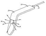
- FIG. 3is a close up view of pre-cut illuminator films with directional beams.
- FIG. 4is a close up view of pre-cut illuminator film with a combination diffuse and directional beam.
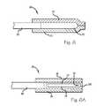
- FIG. 5is a cross-section of an optical fiber termination formed from optical films.
- FIG. 5 ais a cross-section of an alternative optical fiber termination formed from optical films.
- FIG. 6is a cross-section of an optical fiber termination formed from optical films with an air gap.
- FIG. 6 ais a cross-section of an alternative optical fiber termination formed from optical films with an air gap.
- FIG. 7is a cross-section of an optical fiber termination formed from optical films with a light guide section.
- FIG. 8is a perspective view of an illuminator assembly using a fiber optic ribbon cable and optical films.
- FIG. 9is a perspective view of an optical film illumination assembly on a surgical retractor.
- FIG. 10illustrates prismatic structures on optical film.
- Surgical illumination system 10 of FIG. 1includes surgical retractor 12 with handle 12 H, waveguide 14 and fiber optic light guide cable 16 , which is attached to any suitable light source.
- Waveguide 14functions to receive and conduct light from light guide cable 16 and the waveguide contains the light through total internal reflection. Without any surface interruptions, light energy contained in the waveguide would stay contained in the waveguide, subject to minor absorption, refraction and other losses as they occur over time.
- Stick-on illuminator film 17is made from an optical film that changes the refractive index of the area of waveguide 14 to which the film is attached. Stick-on illuminator film 17 is provided with tab 18 to facilitate handling of the illuminator film. When stick-on illuminator film 17 is attached to waveguide 14 , directional light 20 is allowed to escape and illuminate a surgical area of interest.
- Waveguide 14may be connected to an external light source, such as a xenon light source through fiber optic light guide cable 16 , or it may have an integrated light source, such as an integrated LED including drive electronics and battery. Alternatively, waveguide 14 may be attached to a portable light source, such as a portable LED light source.
- an external light sourcesuch as a xenon light source through fiber optic light guide cable 16
- an integrated light sourcesuch as an integrated LED including drive electronics and battery.
- waveguide 14may be attached to a portable light source, such as a portable LED light source.
- the shape of stick-on illuminator 17may be any suitable shape and the shape geometry may be determined, at least in part, by the desired illumination target.
- a circular precut sectionmay be more suitable for a round illumination target and a rectangular precut section may be suitable for a wide angle illumination target.
- Such suitable illumination target geometriesmay be combined to create a combined illumination target.
- a precut sectionmay include a rectangular portion for providing a percentage of the available light for wide angle illumination and a circular portion for providing a percentage of the available light for spot illumination.
- waveguide retractor 22 of FIG. 2serves as the mechanical retractor and the light waveguide and is attached to any suitable light source through fiber optic light guide cable 23 .
- stick-on illuminator film 24is not provided with a tab, and it also provides diffuse illumination 26 that may be suitable for illuminating a larger surgical area than stick-on illuminator film 17 of FIG. 1 .
- illumination 26may be hemispherical, but it may be preferred to reduce the amount of light be reflected back up into a surgeon's eyes.
- Waveguide retractor 22may be a rigid device formed of any suitable material, e.g., molded polycarbonate or acrylic, or may be a flexible device, e.g., molded silicone. Waveguide retractor 22 may be in any suitable shape, e.g., bar, tube, etc. and includes handle 22 H.
- FIG. 3provides a close-up view of surgical illuminator 28 showing distal end 29 of waveguide 30 .
- Directional stick-on illuminator films 32 and 34are shown with respective tabs 33 and 35 that also mark the direction of the respective directed light output 32 L and 34 L, i.e., the light output is in the direction opposite of the tabs.
- Tab 33 of stick-on illuminator film 32is pointed to the right, indicating that the direction of illumination output 32 L is to the left to illuminate area of interest 36 that is to the left of waveguide 30 .
- Tab 35 of stick-on illuminator film 34is pointed to the left, indicating that the direction of illumination output 34 L is to the right to illuminate a particular area of interest 37 that is to the right of waveguide 30 .
- combination pre-cut illuminator film 38incorporates diffuse and focused illumination features.
- Pre-cut, stick-on film element 38is attached to a light conducting waveguide such as waveguide 40 .
- Stick-on film element 38has a diffuse light output portion 42 that creates diffuse light 43 to illuminate a general surgical area and has a directed light output portion 44 that creates directed light 45 that illuminates a specific surgical area such as area 46 .
- Pre-cut, stick-on film element 38is fabricated using standard film converting techniques. Again, the user positions the waveguide, then applies the stick-on illuminator film, or the illuminator film may be pre-applied to the waveguide before positioning the waveguide into the surgical field.
- the diffuse output portionmay be designed to provide any pattern of diffuse light, e.g., lambertian, planar, curved, etc.
- the directed output portionmay be designed to provide any pattern of directed light, e.g., circular, polygonal, etc.
- the diffuse output portionmay even be constructed using two or more directional optical films providing two or more directional illumination outputs, e.g., a circular spot of light to the right of the waveguide midline and a square spot of light to the left of the waveguide midline.
- Optical termination 48 of FIG. 5is formed of laminated optical film elements such as film elements 49 and 50 at the end of any suitable light guide such as fiber optic cable 52 .
- Optical film 49is illustrated as the lower portion with adhesive layer 53 and preferably serves a reflective function sending light to the upper portion.
- Optical film 50is the transmissive upper portion with adhesive layer 55 and may operate in a focused light directing function or a light diffusing mode or both.
- adhesive layers 53 and 55are thick enough and have sufficient optical clarity to allow light from fiber 52 , which may be a fiber bundle or a fiber ribbon cable or other suitable arrangement of fibers, to propagate at least partially along the adhesive layers so that light exits substantially along output surface 54 of optical film 50 that extends beyond fiber 52 .
- the film layersmay be shortened as shown in FIG. 5A , showing alternative cable illuminator 58 which includes light cable 60 , upper light directing film 62 and lower light reflecting film 64 .
- Light exiting light cable 60encounters lower reflecting film 64 , causing the light to be directed toward upper light directing film 62 , which may be configured to deliver diffuse light such as light 65 , directed light such as light 66 or some combination thereof.
- upper light directing film 62may be configured to deliver diffuse light such as light 65 , directed light such as light 66 or some combination thereof.
- some lightmay shine out the end of illuminator 58 and may actually shine downward direction past lower light reflecting film 64 .
- lower light reflecting film 64may be replaced with another piece of upper light directing film 62 to convert the highly Gaussian distributed light from light cable 60 to a more diffuse distribution that may be more useful in a diagnostic or therapeutic application or in an application where light shining in more than one direction is desired.
- laminated optical termination 68is configured to engage any suitable light input structure such as an optical fiber bundle or a single core optical fiber or a length of polycarbonate, acrylic, silicone or other suitable light-conducting material such as light conduit or cable 70 .
- Light reflecting film 71directs light from light cable 70 above to light output film 72 , which may provide diffuse illumination, directional illumination or a combination thereof.
- an air chambersuch as air chamber 73 is created to allow all the light from light cable 70 above to be directed down the length of the optical film laminate structure created by joining films 71 above and 72 above along their edges.
- Films 71 above and 72 aboveare preferably cut in a rectangular shape, but may also be cut in any other suitable shape.
- air chamber 74 of laminated optical termination 76may be supported by a frame such as frame 77 made of a suitable material, e.g., plastic or metal, to help keep the air chamber open during use.
- Directing film 78 and reflecting film 79perform the same function as the respective films in FIG. 6 .
- Frame 77may have a reflective surface at end 77 E opposite of the light input from input cable 80 or may have a layer of reflective film 81 to help ensure that light only exits directing film 78 .
- laminated film terminator 82is sized to engage light input cable 84 , which is preferably a fiber optic ribbon with the fibers generally planar in a side by side orientation.
- Reflecting film 89serves to direct light toward output film 87 .
- Termination waveguide 88may be fabricated from any suitable optical material such as polycarbonate, acrylic or silicone or another layer of optical film. In this configuration, the thickness of termination waveguide 88 is at least the same thickness as light input cable 84 to help ensure that all light from light input cable 84 enters termination waveguide 88 .
- Termination waveguide 88may also incorporate optical structures, e.g., that are molded in or created via a hot stamp process that may help direct the light from light input cable 84 out to a surgical area to be illuminated.
- a laminated film terminationsuch as termination 90 of FIG. 8 engages a suitable light input element, for example, a fiber optic ribbon cable such as ribbon cable 92 .
- a fiber optic ribbon cablesuch as ribbon cable 92 .
- Output or top film 93 and reflective or bottom film 94are adhered together along terminator edges 90 E.
- fiber optic ribbon cable 92may have fibers extending the entire length of the laminated termination.
- the lightmay escape individual fibers where each fiber contacts top film 93 and/or bottom film 94 , or the fibers may be nicked or otherwise treated to allow light to escape the fibers directly without the need to contact either the top film or the bottom film.
- Fiber optic ribbon cable 92may be a bundle of fibers whose cut ends are arranged in a particular shape, e.g., the bundle may be round at the input connector and may be rectangular or some other shape at the film laminate end, it may be a ribbon cable where fibers are typically arranged side to side, or it may be a single core fiber.
- Laminated illuminator system 96 of FIG. 9includes laminated film termination 97 on light input cable 98 attached to a retractor such as retractor 99 having handle 99 H.
- Input connector 100serves to connect the illuminator system to a source of light.
- Light input cable 98conducts light from connector 100 to the film laminate structure 97 , which directs light 101 to a surgical area 102 to be illuminated.
- Adhesivemay be provided along light input cable 98 and/or film laminate structure 97 for attaching the illuminator film assembly to retractor 99 .
- a film illumination systemmay comprise one or more pre-cut sections of optical film, the pre-cut film sections including optical structures, for example, prismatic structures 1004 , for directing or focusing or diffusing light entering one side of the film 1002 as it exits the opposite side of the film 1002 .
- optical structuresfor example, prismatic structures 1004
Landscapes
- Health & Medical Sciences (AREA)
- Life Sciences & Earth Sciences (AREA)
- Surgery (AREA)
- Veterinary Medicine (AREA)
- Public Health (AREA)
- General Health & Medical Sciences (AREA)
- Animal Behavior & Ethology (AREA)
- Biomedical Technology (AREA)
- Molecular Biology (AREA)
- Engineering & Computer Science (AREA)
- Nuclear Medicine, Radiotherapy & Molecular Imaging (AREA)
- Heart & Thoracic Surgery (AREA)
- Medical Informatics (AREA)
- Pathology (AREA)
- Radiology & Medical Imaging (AREA)
- Optics & Photonics (AREA)
- Physics & Mathematics (AREA)
- Biophysics (AREA)
- Oral & Maxillofacial Surgery (AREA)
- Dentistry (AREA)
- Epidemiology (AREA)
- Surgical Instruments (AREA)
- Light Guides In General And Applications Therefor (AREA)
Abstract
Description
Claims (15)
Priority Applications (3)
| Application Number | Priority Date | Filing Date | Title |
|---|---|---|---|
| US13/366,140US8596847B2 (en) | 2006-06-13 | 2012-02-03 | Film illumination system |
| US14/068,971US9220401B2 (en) | 2006-06-13 | 2013-10-31 | Film illumination system |
| US14/948,048US20160074126A1 (en) | 2006-06-13 | 2015-11-20 | Film illumination system |
Applications Claiming Priority (4)
| Application Number | Priority Date | Filing Date | Title |
|---|---|---|---|
| US81339106P | 2006-06-13 | 2006-06-13 | |
| US11/818,090US7686492B2 (en) | 2006-06-13 | 2007-06-12 | Film illumination system |
| US12/750,581US8132949B2 (en) | 2006-06-13 | 2010-03-30 | Film illumination system |
| US13/366,140US8596847B2 (en) | 2006-06-13 | 2012-02-03 | Film illumination system |
Related Parent Applications (1)
| Application Number | Title | Priority Date | Filing Date |
|---|---|---|---|
| US12/750,581ContinuationUS8132949B2 (en) | 2006-06-13 | 2010-03-30 | Film illumination system |
Related Child Applications (1)
| Application Number | Title | Priority Date | Filing Date |
|---|---|---|---|
| US14/068,971ContinuationUS9220401B2 (en) | 2006-06-13 | 2013-10-31 | Film illumination system |
Publications (2)
| Publication Number | Publication Date |
|---|---|
| US20120136216A1 US20120136216A1 (en) | 2012-05-31 |
| US8596847B2true US8596847B2 (en) | 2013-12-03 |
Family
ID=38832503
Family Applications (5)
| Application Number | Title | Priority Date | Filing Date |
|---|---|---|---|
| US11/818,090Expired - Fee RelatedUS7686492B2 (en) | 2006-06-13 | 2007-06-12 | Film illumination system |
| US12/750,581Expired - Fee RelatedUS8132949B2 (en) | 2006-06-13 | 2010-03-30 | Film illumination system |
| US13/366,140Expired - Fee RelatedUS8596847B2 (en) | 2006-06-13 | 2012-02-03 | Film illumination system |
| US14/068,971Expired - Fee RelatedUS9220401B2 (en) | 2006-06-13 | 2013-10-31 | Film illumination system |
| US14/948,048AbandonedUS20160074126A1 (en) | 2006-06-13 | 2015-11-20 | Film illumination system |
Family Applications Before (2)
| Application Number | Title | Priority Date | Filing Date |
|---|---|---|---|
| US11/818,090Expired - Fee RelatedUS7686492B2 (en) | 2006-06-13 | 2007-06-12 | Film illumination system |
| US12/750,581Expired - Fee RelatedUS8132949B2 (en) | 2006-06-13 | 2010-03-30 | Film illumination system |
Family Applications After (2)
| Application Number | Title | Priority Date | Filing Date |
|---|---|---|---|
| US14/068,971Expired - Fee RelatedUS9220401B2 (en) | 2006-06-13 | 2013-10-31 | Film illumination system |
| US14/948,048AbandonedUS20160074126A1 (en) | 2006-06-13 | 2015-11-20 | Film illumination system |
Country Status (2)
| Country | Link |
|---|---|
| US (5) | US7686492B2 (en) |
| WO (1) | WO2007146314A2 (en) |
Cited By (17)
| Publication number | Priority date | Publication date | Assignee | Title |
|---|---|---|---|---|
| US20140057223A1 (en)* | 2006-06-13 | 2014-02-27 | Invuity, Inc. | Film illumination system |
| US9867602B2 (en) | 2015-02-05 | 2018-01-16 | Obp Medical Corporation | Illuminated surgical retractor |
| US9913577B2 (en) | 2010-09-28 | 2018-03-13 | Obp Medical Corporation | Speculum |
| US10278572B1 (en) | 2017-10-19 | 2019-05-07 | Obp Medical Corporation | Speculum |
| US10420538B2 (en) | 2015-02-05 | 2019-09-24 | Obp Medical Corporation | Illuminated surgical retractor |
| US10512519B2 (en) | 2018-02-20 | 2019-12-24 | Obp Medical Corporation | Illuminated medical devices |
| US10687793B2 (en) | 2017-07-18 | 2020-06-23 | Obp Medical Corporation | Minimally invasive no touch (MINT) procedure for harvesting the great saphenous vein (GSV) and venous hydrodissector and retractor for use during the MINT procedure |
| US10722621B2 (en) | 2016-07-11 | 2020-07-28 | Obp Medical Corporation | Illuminated suction device |
| US10799229B2 (en) | 2018-02-20 | 2020-10-13 | Obp Medical Corporation | Illuminated medical devices |
| USD904607S1 (en) | 2019-05-07 | 2020-12-08 | Obp Medical Corporation | Nasal retractor |
| US10881387B2 (en) | 2015-06-03 | 2021-01-05 | Obp Medical Corporation | Retractor |
| USD911521S1 (en) | 2019-02-19 | 2021-02-23 | Obp Medical Corporation | Handle for medical devices including surgical retractors |
| US10939899B2 (en) | 2015-06-03 | 2021-03-09 | Obp Medical Corporation | End cap assembly for retractor and other medical devices |
| US10952712B2 (en) | 2015-06-03 | 2021-03-23 | Obp Medical Corporation | Retractor |
| US10959609B1 (en) | 2020-01-31 | 2021-03-30 | Obp Medical Corporation | Illuminated suction device |
| US10966702B1 (en) | 2020-02-25 | 2021-04-06 | Obp Medical Corporation | Illuminated dual-blade retractor |
| US12318080B2 (en) | 2023-07-21 | 2025-06-03 | Coopersurgical, Inc. | Illuminated surgical retractor capable of hand-held operation and of being mounted to a fixed frame |
Families Citing this family (50)
| Publication number | Priority date | Publication date | Assignee | Title |
|---|---|---|---|---|
| US9216015B2 (en) | 2004-10-28 | 2015-12-22 | Vycor Medical, Inc. | Apparatus and methods for performing brain surgery |
| US20060287583A1 (en)* | 2005-06-17 | 2006-12-21 | Pool Cover Corporation | Surgical access instruments for use with delicate tissues |
| US8360970B2 (en)* | 2005-06-22 | 2013-01-29 | Vycor Medical, Inc. | Surgical access instruments for use with spinal or orthopedic surgery |
| US20080033251A1 (en)* | 2006-06-30 | 2008-02-07 | Ali Araghi | Surgical retractor and method of use |
| US8062217B2 (en)* | 2007-01-26 | 2011-11-22 | Theken Spine, Llc | Surgical retractor with removable blades and method of use |
| US20080183044A1 (en)* | 2007-01-26 | 2008-07-31 | Dennis Colleran | Flexible surgical retractor and method of use |
| US8088066B2 (en) | 2007-10-24 | 2012-01-03 | Invuity, Inc. | Blade insert illuminator |
| GB0800835D0 (en) | 2008-01-17 | 2008-02-27 | Cardioprec Ltd | Retractor |
| US11382711B2 (en) | 2008-08-13 | 2022-07-12 | Invuity, Inc. | Cyclo olefin polymer and copolymer medical devices |
| US8317693B2 (en)* | 2008-08-13 | 2012-11-27 | Invuity, Inc. | Cyclo olefin polymer and copolymer medical devices |
| US9282878B2 (en) | 2008-08-13 | 2016-03-15 | Invuity, Inc. | Cyclo olefin polymer and copolymer medical devices |
| US8992558B2 (en) | 2008-12-18 | 2015-03-31 | Osteomed, Llc | Lateral access system for the lumbar spine |
| US8292805B2 (en) | 2009-11-10 | 2012-10-23 | Invuity, Inc. | Illuminated suction apparatus |
| US8945003B2 (en)* | 2010-01-12 | 2015-02-03 | Tedan Surgical | Surgical retractor with curved rotating blades |
| KR101061695B1 (en) | 2010-01-15 | 2011-09-01 | (주)티디엠 | Detachable clip-type medical light fixture |
| GB201015746D0 (en) | 2010-09-21 | 2010-10-27 | Cardioprec Ltd | Optical switch |
| US9011323B2 (en)* | 2010-10-08 | 2015-04-21 | Invuity, Inc. | Method and apparatus for soft tissue retraction |
| US10292784B2 (en)* | 2010-12-10 | 2019-05-21 | Illumix Surgical Canada Inc. | Illuminating surgical device |
| US9757109B2 (en)* | 2010-12-10 | 2017-09-12 | Illumix Surgical Canada Inc. | Organic light emitting diode illuminated surgical retractor |
| KR20140069254A (en) | 2011-09-23 | 2014-06-09 | 인뷰이티, 인코포레이티드 | Illuminated and modular soft tissue retractor |
| US9622779B2 (en) | 2011-10-27 | 2017-04-18 | DePuy Synthes Products, Inc. | Method and devices for a sub-splenius / supra-levator scapulae surgical access technique |
| US9114202B1 (en)* | 2011-11-15 | 2015-08-25 | Bionix Development Corporation | Lighted suction device |
| US8899809B2 (en)* | 2012-01-30 | 2014-12-02 | Invuity, Inc. | Illuminated clip and methods of use |
| US20130197313A1 (en)* | 2012-01-31 | 2013-08-01 | Shaw P. Wan | Surgical retractor with light |
| KR102232361B1 (en)* | 2012-09-24 | 2021-03-25 | 인뷰이티 인코퍼레이티드 | Methods and apparatus for controlling optical properties of light |
| US20140121467A1 (en) | 2012-10-31 | 2014-05-01 | Invuity, Inc. | Methods and apparatus for simultaneous retraction and distraction of bone and soft tissue |
| US10039932B2 (en)* | 2012-11-20 | 2018-08-07 | Biolase, Inc. | Eyelid treatment device |
| USD938095S1 (en) | 2013-04-01 | 2021-12-07 | Pathy Medical, Llc | Lighting device |
| RU2705046C2 (en) | 2013-04-01 | 2019-11-01 | Винод В. ПАТХИ | Lighting device |
| US20140323811A1 (en)* | 2013-04-30 | 2014-10-30 | Invuity, Inc. | Methods and apparatus for retracting tissue |
| EP3142541A4 (en) | 2014-05-13 | 2017-04-26 | Vycor Medical, Inc. | Guidance system mounts for surgical introducers |
| EP3145385A4 (en)* | 2014-05-22 | 2018-02-14 | Invuity, Inc. | Medical device featuring cladded waveguide |
| GB2532239A (en)* | 2014-11-12 | 2016-05-18 | Clear Surgical Ltd | Retractor with improved light source, and light source for an improved retractor |
| JP6674952B2 (en)* | 2014-12-08 | 2020-04-01 | インブイティ・インコーポレイテッド | Method and apparatus for electrosurgical lighting and sensing |
| WO2016160529A1 (en)* | 2015-03-30 | 2016-10-06 | Invuity, Inc. | Malleable waveguide |
| JP2018521445A (en)* | 2015-04-10 | 2018-08-02 | スリーエム イノベイティブ プロパティズ カンパニー | Light guide with laminated extraction film |
| US10433960B1 (en) | 2015-05-07 | 2019-10-08 | Cardioprecision Limited | Method and system for transcatheter intervention |
| EP3331469B1 (en)* | 2015-08-05 | 2023-04-19 | Illumix Surgical Canada Inc. | Illuminating surgical device |
| WO2018039228A1 (en) | 2016-08-23 | 2018-03-01 | Stryker European Holdings I, Llc | Instrumentation for the implantation of spinal implants |
| DE102016219276B4 (en)* | 2016-10-05 | 2025-08-07 | Siemens Healthineers Ag | Medical imaging device with a light source for illuminating an examination area |
| US10376258B2 (en) | 2016-11-07 | 2019-08-13 | Vycor Medical, Inc. | Surgical introducer with guidance system receptacle |
| US12178469B2 (en) | 2016-11-07 | 2024-12-31 | Vycor Medical Inc. | Surgical introducer with guidance system receptacle |
| US10543016B2 (en) | 2016-11-07 | 2020-01-28 | Vycor Medical, Inc. | Surgical introducer with guidance system receptacle |
| WO2018140208A1 (en) | 2017-01-24 | 2018-08-02 | Medtronic Advanced Energy Llc | Modular lighted surgical retractor |
| USD846119S1 (en) | 2017-01-24 | 2019-04-16 | Medtronic Advanced Energy Llc | Lighted surgical retractor base |
| WO2019036048A2 (en) | 2017-08-17 | 2019-02-21 | Stryker European Holdings I, Llc | Lateral access bridges, shims and lighting including rod lighting |
| EP3545857B1 (en) | 2018-03-30 | 2024-01-03 | Stryker European Operations Holdings LLC | Lateral access retractor and core insertion |
| US11413029B2 (en) | 2018-10-24 | 2022-08-16 | Stryker European Operations Holdings Llc | Anterior to psoas instrumentation |
| US11564674B2 (en) | 2019-11-27 | 2023-01-31 | K2M, Inc. | Lateral access system and method of use |
| US12171419B2 (en) | 2021-10-06 | 2024-12-24 | K2M, Inc. | Offset Hohmann |
Citations (26)
| Publication number | Priority date | Publication date | Assignee | Title |
|---|---|---|---|---|
| US3638644A (en) | 1969-03-05 | 1972-02-01 | Michael Elbert | Illuminated surgical speculum |
| US3641332A (en) | 1969-10-30 | 1972-02-08 | Ebert Michael | Fiber optics illumination system |
| US3890960A (en) | 1973-01-19 | 1975-06-24 | Efrudec Vertriebsgesellschaft | Medical diagnostic inspection spatula |
| US4226228A (en) | 1978-11-02 | 1980-10-07 | Shin Hee J | Multiple joint retractor with light |
| GB2078526A (en) | 1980-06-21 | 1982-01-13 | Original Hanau Heraeus Gmbh | Improvements in or relating to surgical retractors |
| EP0101781A1 (en) | 1982-07-30 | 1984-03-07 | W.C. Heraeus GmbH | Retractor for surgical purposes |
| US4562832A (en) | 1984-01-21 | 1986-01-07 | Wilder Joseph R | Medical instrument and light pipe illumination assembly |
| US4592344A (en) | 1980-07-25 | 1986-06-03 | Scheer Peter M | Combination illuminator and lip and cheek expander |
| US4597030A (en) | 1985-01-31 | 1986-06-24 | American Hospital Supply Corporation | Surgical illuminator |
| US4605990A (en) | 1984-01-21 | 1986-08-12 | Wilder Joseph R | Surgical clip-on light pipe illumination assembly |
| US4643172A (en) | 1985-10-21 | 1987-02-17 | Taff Barry E | Luminescent tongue depressor |
| US4697578A (en) | 1981-07-17 | 1987-10-06 | Burgin Kermit H | Acrylooptic tongue depressor and handle therefor incorporating adjustable viewing optics |
| US4807599A (en) | 1987-05-08 | 1989-02-28 | Med-Struments, Inc. | Illuminating tongue depressor |
| US4842356A (en) | 1987-04-15 | 1989-06-27 | Kei Mori | Light ray radiation device for use in medical treatment of the nose and throat passages |
| US4961617A (en) | 1989-07-19 | 1990-10-09 | Ferrydon Shahidi | Fibre optic waveguide illuminating elements |
| US5035232A (en) | 1987-10-24 | 1991-07-30 | Aesculap Ag | Retractor |
| US5353786A (en) | 1992-01-24 | 1994-10-11 | Wilk Peter J | Surgical lighting method |
| US5355284A (en) | 1990-02-20 | 1994-10-11 | K. W. Muth Company, Inc. | Mirror assembly |
| US5807261A (en) | 1992-09-14 | 1998-09-15 | Sextant Medical Corporation | Noninvasive system for characterizing tissue in vivo |
| US6185356B1 (en) | 1995-06-27 | 2001-02-06 | Lumitex, Inc. | Protective cover for a lighting device |
| US20030169603A1 (en) | 2002-03-05 | 2003-09-11 | Luloh K. Peter | Apparatus and method for illuminating a field of view within an eye |
| US20040221375A1 (en) | 2003-02-03 | 2004-11-11 | Douglas Thomas D. A. | Helmet face shield |
| US20070208226A1 (en) | 2006-01-18 | 2007-09-06 | Spotlight Surgical, Inc. | Retractor illumination system |
| US7306559B2 (en) | 1997-07-02 | 2007-12-11 | Lumitex, Inc. | Illuminated surgical retractor |
| US20070293729A1 (en)* | 2006-05-26 | 2007-12-20 | Spotlight Surgical, Inc. | Blade insert illuminator |
| US20080002426A1 (en) | 2006-06-13 | 2008-01-03 | Spotlight Surgical, Inc. | Film illumination system |
- 2007
- 2007-06-12USUS11/818,090patent/US7686492B2/ennot_activeExpired - Fee Related
- 2007-06-13WOPCT/US2007/013829patent/WO2007146314A2/enactiveApplication Filing
- 2010
- 2010-03-30USUS12/750,581patent/US8132949B2/ennot_activeExpired - Fee Related
- 2012
- 2012-02-03USUS13/366,140patent/US8596847B2/ennot_activeExpired - Fee Related
- 2013
- 2013-10-31USUS14/068,971patent/US9220401B2/ennot_activeExpired - Fee Related
- 2015
- 2015-11-20USUS14/948,048patent/US20160074126A1/ennot_activeAbandoned
Patent Citations (29)
| Publication number | Priority date | Publication date | Assignee | Title |
|---|---|---|---|---|
| US3638644A (en) | 1969-03-05 | 1972-02-01 | Michael Elbert | Illuminated surgical speculum |
| US3641332A (en) | 1969-10-30 | 1972-02-08 | Ebert Michael | Fiber optics illumination system |
| US3890960A (en) | 1973-01-19 | 1975-06-24 | Efrudec Vertriebsgesellschaft | Medical diagnostic inspection spatula |
| US4226228A (en) | 1978-11-02 | 1980-10-07 | Shin Hee J | Multiple joint retractor with light |
| GB2078526A (en) | 1980-06-21 | 1982-01-13 | Original Hanau Heraeus Gmbh | Improvements in or relating to surgical retractors |
| US4592344A (en) | 1980-07-25 | 1986-06-03 | Scheer Peter M | Combination illuminator and lip and cheek expander |
| US4697578A (en) | 1981-07-17 | 1987-10-06 | Burgin Kermit H | Acrylooptic tongue depressor and handle therefor incorporating adjustable viewing optics |
| EP0101781A1 (en) | 1982-07-30 | 1984-03-07 | W.C. Heraeus GmbH | Retractor for surgical purposes |
| US4562832A (en) | 1984-01-21 | 1986-01-07 | Wilder Joseph R | Medical instrument and light pipe illumination assembly |
| US4605990A (en) | 1984-01-21 | 1986-08-12 | Wilder Joseph R | Surgical clip-on light pipe illumination assembly |
| US4597030A (en) | 1985-01-31 | 1986-06-24 | American Hospital Supply Corporation | Surgical illuminator |
| US4643172A (en) | 1985-10-21 | 1987-02-17 | Taff Barry E | Luminescent tongue depressor |
| US4842356A (en) | 1987-04-15 | 1989-06-27 | Kei Mori | Light ray radiation device for use in medical treatment of the nose and throat passages |
| US4807599A (en) | 1987-05-08 | 1989-02-28 | Med-Struments, Inc. | Illuminating tongue depressor |
| US5035232A (en) | 1987-10-24 | 1991-07-30 | Aesculap Ag | Retractor |
| US4961617A (en) | 1989-07-19 | 1990-10-09 | Ferrydon Shahidi | Fibre optic waveguide illuminating elements |
| US5355284A (en) | 1990-02-20 | 1994-10-11 | K. W. Muth Company, Inc. | Mirror assembly |
| US5353786A (en) | 1992-01-24 | 1994-10-11 | Wilk Peter J | Surgical lighting method |
| US5807261A (en) | 1992-09-14 | 1998-09-15 | Sextant Medical Corporation | Noninvasive system for characterizing tissue in vivo |
| US6185356B1 (en) | 1995-06-27 | 2001-02-06 | Lumitex, Inc. | Protective cover for a lighting device |
| US6504985B2 (en) | 1995-06-27 | 2003-01-07 | Lumitex, Inc. | Illuminated surgical retractor |
| US7306559B2 (en) | 1997-07-02 | 2007-12-11 | Lumitex, Inc. | Illuminated surgical retractor |
| US20030169603A1 (en) | 2002-03-05 | 2003-09-11 | Luloh K. Peter | Apparatus and method for illuminating a field of view within an eye |
| US20040221375A1 (en) | 2003-02-03 | 2004-11-11 | Douglas Thomas D. A. | Helmet face shield |
| US20070208226A1 (en) | 2006-01-18 | 2007-09-06 | Spotlight Surgical, Inc. | Retractor illumination system |
| US20070293729A1 (en)* | 2006-05-26 | 2007-12-20 | Spotlight Surgical, Inc. | Blade insert illuminator |
| US20080002426A1 (en) | 2006-06-13 | 2008-01-03 | Spotlight Surgical, Inc. | Film illumination system |
| US7686492B2 (en)* | 2006-06-13 | 2010-03-30 | Invuity, Inc. | Film illumination system |
| US8132949B2 (en)* | 2006-06-13 | 2012-03-13 | Invuity, Inc. | Film illumination system |
Non-Patent Citations (3)
| Title |
|---|
| International search report and written opinion dated Jan. 29, 2008 for PCT/US2007/013829. |
| Office action dated Apr. 9, 2009 for U.S. Appl. No. 11/818,090. |
| Office action dated Jul. 1, 2011 for U.S. Appl. No. 12/750,581. |
Cited By (39)
| Publication number | Priority date | Publication date | Assignee | Title |
|---|---|---|---|---|
| US20140057223A1 (en)* | 2006-06-13 | 2014-02-27 | Invuity, Inc. | Film illumination system |
| US9220401B2 (en)* | 2006-06-13 | 2015-12-29 | Invuity, Inc. | Film illumination system |
| US20160074126A1 (en)* | 2006-06-13 | 2016-03-17 | Invuity, Inc. | Film illumination system |
| US10368733B2 (en) | 2010-09-28 | 2019-08-06 | Obp Medical Corporation | Speculum |
| US9913577B2 (en) | 2010-09-28 | 2018-03-13 | Obp Medical Corporation | Speculum |
| US11744454B2 (en) | 2010-09-28 | 2023-09-05 | Obp Medical Corporation | Speculum |
| US12329370B2 (en) | 2015-02-05 | 2025-06-17 | Coopersurgical, Inc. | Illuminated surgical retractor |
| US12089829B2 (en) | 2015-02-05 | 2024-09-17 | Obp Surgical Corporation | Illuminated surgical retractor |
| US10420538B2 (en) | 2015-02-05 | 2019-09-24 | Obp Medical Corporation | Illuminated surgical retractor |
| US10420540B2 (en) | 2015-02-05 | 2019-09-24 | Obp Medical Corporation | Illuminated surgical retractor |
| US9867602B2 (en) | 2015-02-05 | 2018-01-16 | Obp Medical Corporation | Illuminated surgical retractor |
| US11197662B2 (en) | 2015-02-05 | 2021-12-14 | Obp Surgical Corporation | Illuminated surgical retractor |
| US11439379B2 (en) | 2015-02-05 | 2022-09-13 | Obp Surgical Corporation | Illuminated surgical retractor |
| US12201287B2 (en) | 2015-06-03 | 2025-01-21 | Coopersurgical, Inc. | Retractor |
| US10881387B2 (en) | 2015-06-03 | 2021-01-05 | Obp Medical Corporation | Retractor |
| US11622756B2 (en) | 2015-06-03 | 2023-04-11 | Obp Surgical Corporation | End cap assembly for retractor and other medical devices |
| US10939899B2 (en) | 2015-06-03 | 2021-03-09 | Obp Medical Corporation | End cap assembly for retractor and other medical devices |
| US10952712B2 (en) | 2015-06-03 | 2021-03-23 | Obp Medical Corporation | Retractor |
| US10966699B2 (en) | 2015-06-03 | 2021-04-06 | Obp Medical Corporation | Retractor |
| US10722621B2 (en) | 2016-07-11 | 2020-07-28 | Obp Medical Corporation | Illuminated suction device |
| US11717374B2 (en) | 2016-07-11 | 2023-08-08 | Obp Surgical Corporation | Illuminated suction device |
| US11540817B2 (en) | 2017-07-18 | 2023-01-03 | Obp Surgical Corporation | Minimally invasive no touch (MINT) procedure for harvesting the great saphenous vein (GSV) and venous hydrodissector and retractor for use during the mint procedure |
| US10687793B2 (en) | 2017-07-18 | 2020-06-23 | Obp Medical Corporation | Minimally invasive no touch (MINT) procedure for harvesting the great saphenous vein (GSV) and venous hydrodissector and retractor for use during the MINT procedure |
| US10441155B2 (en) | 2017-10-19 | 2019-10-15 | Obp Medical Corporation | Medical devices with battery removal |
| US10912455B2 (en) | 2017-10-19 | 2021-02-09 | Obp Medical Corporation | Medical devices with battery removal |
| US12383129B2 (en) | 2017-10-19 | 2025-08-12 | Coopersurgical, Inc. | Medical devices with battery removal |
| US10278572B1 (en) | 2017-10-19 | 2019-05-07 | Obp Medical Corporation | Speculum |
| US11253145B2 (en) | 2017-10-19 | 2022-02-22 | Obp Medical Corporation | Speculum |
| US10799229B2 (en) | 2018-02-20 | 2020-10-13 | Obp Medical Corporation | Illuminated medical devices |
| US11744568B2 (en) | 2018-02-20 | 2023-09-05 | Obp Surgical Corporation | Illuminated medical devices |
| US10512519B2 (en) | 2018-02-20 | 2019-12-24 | Obp Medical Corporation | Illuminated medical devices |
| USD911521S1 (en) | 2019-02-19 | 2021-02-23 | Obp Medical Corporation | Handle for medical devices including surgical retractors |
| USD904607S1 (en) | 2019-05-07 | 2020-12-08 | Obp Medical Corporation | Nasal retractor |
| US11617822B2 (en) | 2020-01-31 | 2023-04-04 | Obp Surgical Corporation | Illuminated suction device |
| US12246124B2 (en) | 2020-01-31 | 2025-03-11 | Coopersurgical, Inc. | Illuminated suction device |
| US10959609B1 (en) | 2020-01-31 | 2021-03-30 | Obp Medical Corporation | Illuminated suction device |
| US11622758B2 (en) | 2020-02-25 | 2023-04-11 | Obp Surgical Corporation | Illuminated dual-blade retractor |
| US10966702B1 (en) | 2020-02-25 | 2021-04-06 | Obp Medical Corporation | Illuminated dual-blade retractor |
| US12318080B2 (en) | 2023-07-21 | 2025-06-03 | Coopersurgical, Inc. | Illuminated surgical retractor capable of hand-held operation and of being mounted to a fixed frame |
Also Published As
| Publication number | Publication date |
|---|---|
| US7686492B2 (en) | 2010-03-30 |
| US9220401B2 (en) | 2015-12-29 |
| US20080002426A1 (en) | 2008-01-03 |
| US20140057223A1 (en) | 2014-02-27 |
| US8132949B2 (en) | 2012-03-13 |
| WO2007146314A3 (en) | 2008-04-10 |
| WO2007146314A2 (en) | 2007-12-21 |
| US20120136216A1 (en) | 2012-05-31 |
| US20160074126A1 (en) | 2016-03-17 |
| US20100249528A1 (en) | 2010-09-30 |
Similar Documents
| Publication | Publication Date | Title |
|---|---|---|
| US8596847B2 (en) | Film illumination system | |
| US12161301B2 (en) | Blade insert illuminator | |
| US9241617B2 (en) | Blade insert illuminator | |
| US9844364B2 (en) | Retractor illumination system | |
| US20050171408A1 (en) | Light delivery systems and applications thereof | |
| CN102164621A (en) | Cycloolefin polymers and copolymers for medical devices |
Legal Events
| Date | Code | Title | Description |
|---|---|---|---|
| STCF | Information on status: patent grant | Free format text:PATENTED CASE | |
| AS | Assignment | Owner name:SPOTLIGHT SURGICAL, INC., CALIFORNIA Free format text:ASSIGNMENT OF ASSIGNORS INTEREST;ASSIGNORS:VAYSER, ALEX;TRAUNER, KENNETH B.;GREY, THOMAS L.;SIGNING DATES FROM 20070802 TO 20070808;REEL/FRAME:032022/0429 Owner name:INVUITY, INC., CALIFORNIA Free format text:CHANGE OF NAME;ASSIGNOR:SPOTLIGHT SURGICAL, INC.;REEL/FRAME:032113/0681 Effective date:20071108 | |
| AS | Assignment | Owner name:HEALTHCARE ROYALTY PARTNERS II, L.P., CONNECTICUT Free format text:SECURITY AGREEMENT;ASSIGNOR:INVUITY, INC.;REEL/FRAME:032372/0240 Effective date:20140228 | |
| AS | Assignment | Owner name:INVUITY, INC., CALIFORNIA Free format text:MERGER;ASSIGNOR:INVUITY, INC.;REEL/FRAME:035819/0943 Effective date:20150528 | |
| AS | Assignment | Owner name:INVUITY, INC., CALIFORNIA Free format text:RELEASE BY SECURED PARTY;ASSIGNOR:HEALTHCARE ROYALTY PARTNERS II, L.P.;REEL/FRAME:042035/0801 Effective date:20170310 | |
| AS | Assignment | Owner name:MIDCAP FINANCIAL TRUST, AS AGENT, MARYLAND Free format text:SECURITY INTEREST (TERM LOAN);ASSIGNOR:INVUITY, INC.;REEL/FRAME:042053/0284 Effective date:20170310 Owner name:MIDCAP FINANCIAL TRUST, AS AGENT, MARYLAND Free format text:SECURITY INTEREST (REVOLVING LOAN);ASSIGNOR:INVUITY, INC.;REEL/FRAME:042052/0834 Effective date:20170310 | |
| FPAY | Fee payment | Year of fee payment:4 | |
| AS | Assignment | Owner name:INVUITY, INC., CALIFORNIA Free format text:RELEASE BY SECURED PARTY;ASSIGNOR:MIDCAP FINANCIAL TRUST, AS AGENT;REEL/FRAME:047292/0435 Effective date:20181023 Owner name:INVUITY, INC., CALIFORNIA Free format text:RELEASE BY SECURED PARTY;ASSIGNOR:MIDCAP FINANCIAL TRUST, AS AGENT;REEL/FRAME:047719/0034 Effective date:20181023 | |
| FEPP | Fee payment procedure | Free format text:ENTITY STATUS SET TO UNDISCOUNTED (ORIGINAL EVENT CODE: BIG.); ENTITY STATUS OF PATENT OWNER: LARGE ENTITY | |
| FEPP | Fee payment procedure | Free format text:MAINTENANCE FEE REMINDER MAILED (ORIGINAL EVENT CODE: REM.); ENTITY STATUS OF PATENT OWNER: LARGE ENTITY | |
| LAPS | Lapse for failure to pay maintenance fees | Free format text:PATENT EXPIRED FOR FAILURE TO PAY MAINTENANCE FEES (ORIGINAL EVENT CODE: EXP.); ENTITY STATUS OF PATENT OWNER: LARGE ENTITY | |
| STCH | Information on status: patent discontinuation | Free format text:PATENT EXPIRED DUE TO NONPAYMENT OF MAINTENANCE FEES UNDER 37 CFR 1.362 | |
| FP | Lapsed due to failure to pay maintenance fee | Effective date:20211203 |