US8596617B2 - Impact energy dissipation system - Google Patents
Impact energy dissipation systemDownload PDFInfo
- Publication number
- US8596617B2 US8596617B2US12/709,257US70925710AUS8596617B2US 8596617 B2US8596617 B2US 8596617B2US 70925710 AUS70925710 AUS 70925710AUS 8596617 B2US8596617 B2US 8596617B2
- Authority
- US
- United States
- Prior art keywords
- cable
- guardrail
- routing means
- impact
- bar member
- Prior art date
- Legal status (The legal status is an assumption and is not a legal conclusion. Google has not performed a legal analysis and makes no representation as to the accuracy of the status listed.)
- Active, expires
Links
Images


Classifications
- E—FIXED CONSTRUCTIONS
- E01—CONSTRUCTION OF ROADS, RAILWAYS, OR BRIDGES
- E01F—ADDITIONAL WORK, SUCH AS EQUIPPING ROADS OR THE CONSTRUCTION OF PLATFORMS, HELICOPTER LANDING STAGES, SIGNS, SNOW FENCES, OR THE LIKE
- E01F15/00—Safety arrangements for slowing, redirecting or stopping errant vehicles, e.g. guard posts or bollards; Arrangements for reducing damage to roadside structures due to vehicular impact
- E01F15/02—Continuous barriers extending along roads or between traffic lanes
- E01F15/025—Combinations of at least two of the barrier member types covered by E01F15/04 - E01F15/08, e.g. rolled steel section or plastic strip backed up by cable, safety kerb topped by rail barrier
- E—FIXED CONSTRUCTIONS
- E01—CONSTRUCTION OF ROADS, RAILWAYS, OR BRIDGES
- E01F—ADDITIONAL WORK, SUCH AS EQUIPPING ROADS OR THE CONSTRUCTION OF PLATFORMS, HELICOPTER LANDING STAGES, SIGNS, SNOW FENCES, OR THE LIKE
- E01F15/00—Safety arrangements for slowing, redirecting or stopping errant vehicles, e.g. guard posts or bollards; Arrangements for reducing damage to roadside structures due to vehicular impact
- E01F15/02—Continuous barriers extending along roads or between traffic lanes
- E01F15/06—Continuous barriers extending along roads or between traffic lanes essentially made of cables, nettings or the like
- E—FIXED CONSTRUCTIONS
- E01—CONSTRUCTION OF ROADS, RAILWAYS, OR BRIDGES
- E01F—ADDITIONAL WORK, SUCH AS EQUIPPING ROADS OR THE CONSTRUCTION OF PLATFORMS, HELICOPTER LANDING STAGES, SIGNS, SNOW FENCES, OR THE LIKE
- E01F15/00—Safety arrangements for slowing, redirecting or stopping errant vehicles, e.g. guard posts or bollards; Arrangements for reducing damage to roadside structures due to vehicular impact
- E01F15/14—Safety arrangements for slowing, redirecting or stopping errant vehicles, e.g. guard posts or bollards; Arrangements for reducing damage to roadside structures due to vehicular impact specially adapted for local protection, e.g. for bridge piers, for traffic islands
- E01F15/143—Protecting devices located at the ends of barriers
Definitions
- This inventionrelates to impact energy dissipation systems and in particular, though not solely, to guardrails and/or guardrail impact heads for use in road networks and/or vehicle road lanes requiring separation by a barrier.
- Existing highway guardrail end treatment systemsinclude: the breakaway cable terminal (BCT), the eccentric loader terminal (ELT), the modified eccentric loader terminal (MELT), the vehicle attenuating terminal (VAT), the extruder terminal (ET 2000 and ET plus), the slotted rail terminal (SRT), the sequential kinking terminal (SKT) and the flared energy absorbing terminal (FLEAT).
- Terminal endsthat is, the end facing oncoming traffic
- Terminal endsgenerally consist of one or more, often three, W shaped (in cross-section) guardrails supported by a series of both controlled release terminal (CRT) or frangible posts and standard highway guardrail posts.
- CRTcontrolled release terminal
- a cable assembly arrangementis utilised that anchors the end of the rail to the ground, transferring tensile load developed in a side-on impact by an errant vehicle to the ground anchor.
- the terminal endshave an impact head arrangement that will be the first part impacted by an errant vehicle during an end-on impact which is designed to spread or absorb some of the impact energy.
- Some terminal endssuch as the abovementioned ET, SKT and FLEAT, absorb the energy of the impacting vehicle during an end on impact by having an impact head that slides down the W shaped guardrails, extruding it and breaking away the support posts as it travels down the rails. All of the other abovementioned terminal ends work on the principal of various weakening devices in the posts and rails to allow an errant vehicle to penetrate the terminal end in a controlled manner and prevent the rails from spearing the vehicle or the vehicle from vaulting or jumping over a relatively stiff terminal end.
- guardrail terminal endsare considered to be gating, that is, if impacted between the impact head and the “length of need” (where the “length of need” is considered to be the distance from the terminal end to where the guardrail will redirect a vehicle during an angled impact) during an angled impact, the terminal end will gate and allow the errant vehicle to pass to the back side of the terminal end.
- this gating effectmay have undesirable or unsafe results, and preferably an improved or safer or varied energy absorbing system is utilised to control errant vehicle barrier/guardrail impacts.
- the inventionmay broadly be said to consist in an impact head for a guardrail comprising:
- a cable routing meanswhich forms a tortuous path through which a cable is adapted to be threaded.
- the cable routing means for use in the impact head according to the inventionmay be any member through which a cable may pass and that provides a tortuous path through which said cable may be threaded.
- the tortuous pathmay be any path that provides sufficient friction to slow down the movement of the impact head during a vehicle impact.
- the tortuous nature of the passage through the cable routing meansmay be provided by one or more turns through which a cable may be threaded.
- the tortuous nature of the passage through the cable routing meansmay be provided by one or more turns of greater than substantially 90° through which a cable may be threaded.
- the cable routing meansincludes at least one substantially 180° turn.
- the cable routing meansincludes at least one substantially S or Z-shaped turn.
- the cable routing meansmay be adapted so that in use and during a collision or impact with the impact head, the cable is forced through the cable routing means, where resistance to cable movement provided by the tortuous cable path substantially facilitates impact energy dissipation.
- the cable routing meansis adapted so that when a predetermined level of force is applied to the impact head the one or more cables are forced through the cable routing means, where resistance to cable movement provided by the tortuous cable path limits any movement of the impact head caused by the force.
- the cable routing meansmay include a member having two or more cable entry ports provided therein through which a cable may be threaded.
- the cable routing meanscomprises a bar member having a longitudinal axis and including a cable entry port adapted to allow a cable to pass directly therethrough when said bar member is in a first non-cable-routing orientation, and wherein upon rotation of said bar member through at least 90° about said longitudinal axis, a second cable-routing orientation is reached.
- the bar membermay be secured in the second orientation by locking means in the form of bolts, screws and the like.
- the cablemay be anchored at one point, pass through the impact head according to the invention and then be anchored at another point such that the impact head is substantially between the two anchor points.
- the cablesmay be anchored to any object capable of providing sufficient inertia to restrict cable movement relative to the ground.
- the cablesmay be either directly or indirectly anchored to the ground.
- the impact head according to the present inventionmay be manufactured from any resilient or impact resistant material or composite of materials of any nature.
- the impact head and/or the guardrailmay be constructed from steel.
- one or more cablesmay be threaded through the cable routing means. These cables may preferably be tensioned and anchored at one or more points. In those embodiments where the cable(s) is/are anchored, they may be preferably anchored at one end via a rail and/or a support post of the guardrail.
- the one or more cablesmay be anchored at one end in a position down-road of the proposed traffic flow away from the impact head and the other end(s) may be anchored to a rail and/or a support post substantially up-road of the said impact head.
- the cablemay be high-tensile steel.
- the tension of one or more cablesmay be adjusted so as to give a suitable resistance to movement.
- the present inventionalso provides a guardrail including:
- the at least one cablemay be located within recesses within the plurality of a slidably interconnected rails.
- the slidably connected railstelescope upon an impact substantially in-line with the longitudinal direction of the slidable rails.
- the railsare separated from the support posts by a spacer.
- frangible fastenersconnect a plurality of rails to one another and/or to said posts.
- the inventionmay broadly be said to consist in a guardrail comprising:
- the end of at least one cable located farthest from the cable routing meansis anchored to a rail and/or a support post.
- the impact headis mounted to a first support post.
- the impact headis mounted to a rail.
- the cable routing meansmay be mounted to a first support post or to a rail.
- the cable routing meansis connected to an end of a plurality of interconnected rails.
- rotation of the bar member from said first orientation to said second orientationensures that the cable follows a tortuous pathway.
- the present inventionalso relates to a method of constructing a guardrail including the steps of slidably interconnecting a plurality of rails and attaching them to posts, positioning an impact head according to the invention at one end of the slidably interconnected rails, threading at least one cable through the impact head and anchoring the cable to the ground.
- the method of constructing a guardrailmay include the steps of:
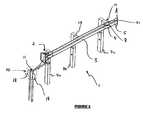
- FIGS. 1 a and 1 bare perspective views from the front or roadway side of one embodiment of a guardrail according to the present invention.
- FIGS. 2 a and 2 bare perspective views from the rear of the guardrail of FIGS. 1 a and 1 b.
- FIG. 3is an alternative embodiment of the guardrail of FIG. 1 a.
- FIG. 4is an alternative embodiment of the guardrail of FIG. 2 a.
- FIG. 5is a front elevation view of one embodiment of a cable routing means according to the present invention.
- FIG. 6Ais a cross sectional schematic plan view of the bar member of the cable routing means of FIG. 5 when in a non-cable routing orientation with the path of the cable indicated by arrow Y;
- FIG. 6Bis a cross sectional schematic plan view illustrating the rotation through which the bar member of the cable routing means of FIG. 6A moves to a second cable routing orientation with the path of the cable indicated by arrow Y.
- This inventionis designed to be a substantially non-gating guardrail, meaning that at any point along the side of the guardrail from the terminal end onwards, an impacting vehicle on an angled collision may be substantially redirected away from its initial impact trajectory. It is also designed to substantially absorb energy during an end on impact to the terminal end.
- Treatingis a term used within the guardrail industry to refer to sections of guardrail which are unable to withstand high impact side angle collisions, and significant guardrail deformation or ultimate failure or breakage may occur.
- FIGS. 1A and 1Bwill be referred together as FIG. 1 ; similarly FIGS. 2A and 2B will be referred to as FIG. 2 .
- the guardrail 1 shownhas been split into two sections for illustrative purposes only, and sections A and A′ in FIGS. 1 a and 1 b ; and the same sections are labelled B and B′ in FIGS. 2A and 2B should be joined to show an embodiment the guardrail according to the present invention.
- a guardrail 1with a cable routing means 2 at the terminal end.
- the cable routing means 2may form part of an impact head (where an impact head is an additional guardrail bumper used to initially absorb some impact energy).
- the cable routing means 2may be bolted to the first rail 3 , at the other end of which is connected an impact slider device 4 .
- the impact slider device 4may facilitate the sliding of the first rail over each subsequent rail, thereby providing substantial telescoping ability to the guardrail, ( 1 ) with each rail overlapping the next rail to enable this process during an end-on impact.
- First rail ( 3 )telescoping over second subsequent rail ( 5 ) and second subsequent rail ( 5 ) telescoping over further subsequent rail ( 6 ) during an end-on impact. It would be obvious to a person skilled in the art that any number of preceding rails could telescope over a further subsequent rail (not shown), therefore the number of telescoping rails should not be seen as being limiting.
- the impact slider assembly ( 4 )may substantially surround the first rail ( 3 ) and advantageously includes an impact slider panel ( 33 ), most clearly shown in FIG. 10 .
- the rails ( 3 , 5 , 6 )may be supported by upstanding CRT (controlled release terminal) ( 7 a , 7 b , 7 c , 7 d ) and/or frangible posts and/or posts of a predetermined failure load or any combination of these post types which will now be collectively referred to by designation ( 7 ).
- the rails ( 3 , 5 , 6 )may be directly attached (not shown) to the posts, ( 7 ) or alternatively may be indirectly attached via spacers ( 17 ) or similar block type arrangement.
- the impact slider assembly ( 4 )may also be used to detach or facilitate the disjointing or disconnection of a connection such as a frangible bolt ( 8 ) between a rail ( 3 , 5 , 6 ) and a CRT ( 7 ).
- a connectionsuch as a frangible bolt ( 8 ) between a rail ( 3 , 5 , 6 ) and a CRT ( 7 ).
- the impact slider assembly ( 4 )is a structural member of suitable strength that allows the bolts ( 8 ) (or similar connector) connecting rail ( 5 ) to posts ( 7 c,d,e ); or rail ( 5 ) to rail ( 3 ) or the next rail ( 6 ); to either be severed from the rail or pulled or bent free from the rail connection.
- the rails ( 3 , 5 , 6 )may be connected to each other separately from support post connections ( 8 ).
- the bolts ( 8 )may be made of materials such as plastics or high density plastic or other composite materials, or frangible bolts, which are more likely to fail and shear off from the post connection (or from the rail to rail connection) by an impact from the impact slider assembly ( 4 ), than a side angle impact with the guardrails ( 3 , 5 , 6 ). This may be an advantageous feature allowing the impact slider assembly ( 4 ) to operate and shear off post holding rail bolts ( 8 ), whilst at the same time providing resistance to side angle impacts and reducing the likelihood of the guardrail gating.
- a cable (or cables) 15 a , 15 bhas an end 10 which may be attached to a soil anchor assembly ( 9 ) or otherwise fixed adjacent (not shown) the impact head ( 24 ).
- the other cable end ( 11 a , 11 b )extends to a second anchor or fixed point, which may be a further soil anchor assembly (not shown), or alternatively, may be an anchoring assembly attached to a non-frangible support post (not shown) or non-telescoping rail ( 16 ).
- the cable ( 15 a , 15 b )may be anchored by cable brackets ( 13 a , 13 b ) to the posts ( 7 a - g ) or a non-telescoping rail ( 16 ) or by any suitable cable anchoring system, such as bolts and welds or the like.
- the soil anchor assembly ( 9 )may include a sunken post (or I-beam) with flares or winged portions ( 18 ) extending outwards from the post to engage with greater soil area and providing increased resistance to movement of the anchor assembly ( 9 ) as a result of an impact with the guardrail ( 1 ).
- FIGS. 1 and 2 of a guardrail ( 1 )consists of a soil anchoring system ( 9 ) at the impact head ( 24 ) end of the guardrail ( 1 ) and provides a means to attach two cables ( 15 a , 15 b ) thereto.
- the cables ( 15 a , 15 b )are preferably threaded in a substantially S-shape (or Z-shape), through the cable routing means ( 2 ), which may be a steel plate bolted to the impact head ( 24 ) (or first post 7 a ).
- up-roadwill for the purposes of this specification be used to describe a position on one side of a road that is located some distance further along that one side of the road in relation to a vehicle correctly travelling on said side of the road. It would be apparent that given this definition, that to vehicles travelling correctly on opposite sides of the same road, up-road will be in opposing directions.
- the railmay be a W-shaped extrusion, the lower portion of the W preferably forming the front or road side of the rail, the cable ( 15 a ,) being located in one channel formed by the W and cable ( 15 b ) being located in the other).
- the cables ( 15 a , 15 b )may extend until a point ( 11 a , 11 b ) where they may be anchored to the rail ( 13 a , 13 b ) (or post, or other anchoring means) at a post up-road of the cable routing means ( 2 ) using one or more cable brackets ( 13 a , 13 b ) or other connecting and/or cable fixing means.
- Such meansmay be screws, bolts, welded joints or other suitable devices enabling substantially secure cable anchoring.
- the cable ( 15 a , 15 b )may be tensioned, although this is not essential for the present invention to operate.
- the guardrail 24includes: at least one cable routing means through which a cable is threaded in a tortuous path and which thereby provides resistance to cable movement therethrough.
- the path of the cable through the cable routing meansincludes at least one substantially 180° turn, or is in a substantially S or Z-shape.
- the at least one cableis forced through the cable routing means ( 2 ), where resistance to cable movement substantially facilitates impact energy dissipation.
- the cable routing means ( 2 ), as most clearly illustrated in FIGS. 3 and 4 ,may be a planar bar member ( 25 ) adapted to receive and allow at least one cable ( 15 , 15 a ) to pass therethrough via cable entry ports (P 1 , P 2 ).
- the planar bar member ( 25 )being rotatable about its longitudinal axis between a non tortuous orientation, as shown in FIG. 6 a , and a tortuous orientation, as shown in FIG. 6 b .
- the tortuous orientationforming a tortuous cable path which provides resistance to cable movement therethrough, such as is illustrated in FIG. 6 b.
- a bar member ( 25 )can be provided with a cable entry port or ports (P 1 , P 2 ) adapted to receive and allow at least one cable to pass directly therethrough, when said bar member is in a first non-cable-routing orientation ( 26 ), the cable path indicated by arrow Y. Subsequently, upon rotation of the bar member ( 25 ) about its longitudinal axis (substantially perpendicular to the cables length) through at least 90°, a second cable-routing orientation ( 27 ) is reached.
- the bar member ( 25 )may be secured in the second orientation by locking means (not shown), such as by bolts or screws.
- the rotation of the bar member ( 25 ) from said first orientation ( 26 ) to the second orientation ( 27 )ensures that the at least one cable follows a tortuous pathway, the tortuous cable path indicated by arrow Y in FIG. 6 b .
- the rotation of the bar member ( 25 )may be undertaken, for example by a crowbar inserted into a slot ( 51 ) and then an angular or rotational force applied. This is illustrated more clearly in the schematic drawings of FIGS. 6 a and 6 b where the bar 25 rotates about pivot point 200 in the direction of arrow X to form the tortuous path.
- energy from a head on impact with the impact head ( 24 )is initially substantially absorbed by support post ( 7 a ), which may subsequently fail, preferably substantially at or near ground level.
- the first support post ( 7 a )would normally be impacted at or by the impact head ( 24 ), and absorb energy before preferably failing (that is, being broken).
- the impacting vehiclemay collide with the broken post which may result in more severe impact energy absorption (possibly resulting in vehicle occupant damage due to sudden movement arrest).
- the guardrail ( 1 )employs energy absorption/dissipation systems which substantially control an impacting objects momentum and directional motion.
- energymay be absorbed or dissipated by the friction between the cable ( 15 a , 15 b ) and cable routing means ( 2 ).
- the guardrail ( 1 )is impacted end on (that is, in the substantially longitudinal direction of the guardrail and impacting the impact head ( 24 ) initially)
- the whole of rail ( 3 ), the impact head ( 24 ), cable routing means ( 2 ) and the impact slider assembly or part thereof ( 4 )move in a telescoping manner over rail ( 5 ) and then subsequent up-road rails, such as rail ( 6 ).
- the cable routing means ( 2 )is attached to, or forms an integral part of an impact head ( 24 ), as the impact head ( 24 ) and cable routing means ( 2 ) move (as a result of an end-on impact with the impact head ( 1 )), up road from the cable anchor point ( 11 ), the cable routing means ( 2 ) is effectively forced to move along the cable(s) ( 15 a , 15 b ), whilst the cable(s) ( 15 , 15 a ) remain substantially stationary as a result of being fixed at each of their ends. In doing so, the cable is forced through a number of bending movements created by the routing configuration in the cable routing means ( 2 ).
- the cable ( 15 a , 15 b ) usedhas substantial resistance to flexing (such as steel cable), and energy is dissipated from the impact and imparted to energy used to bend the cable.
- the cable routing means ( 2 )moves along the cable(s) ( 15 and 15 a ), the cable is forced to run in surface-to-surface contact with the cable routing means ( 2 ), which preferably results in additional frictional energy dissipation.
- the cable routing means ( 2 )may be in the form of a sleeve (not shown) fitted around the cable ( 15 , 15 a ) which is snug around the cable and provides frictional resistance to relative movement of either the sleeve or cable.
- the friction created by the impact slider assembly ( 4 ) (and rails 3 , 5 , 6 ) telescoping over one another during an impact eventmay help to absorb energy.
- Energy from a side angle impact with the guardrail 1is absorbed by the flexion and/or deformation (whether by elastic or plastic deformation) of the rails ( 3 , 5 , 6 ), as well as by the tensile forces created in the cable(s) 15 , 15 a (which may help the rails to resist flexion and/or deformation).
- the impacting objectis redirected away from the guardrail 1 and the forces generated by the impact are distributed throughout the rails ( 3 , 5 , 6 ) and cables ( 15 a , 15 b ) either by deformation or tension generated in the cables ( 15 a , 15 b ) and subsequently redirected to the cable fixing point ( 11 , 11 a ).
- a number of support posts ( 7 a - 7 g )may be frangible or of a predetermined failure load which fail or substantially deform, consequently absorbing further impact energy.
- an objectsuch as a vehicle, involved in a side angle impact is substantially redirected away from the guardrail ( 1 ), and back onto the road, and the rail ( 3 , 5 , 6 ) is restrained from “gating” by the further tension created in the cables ( 15 a , 15 b ) by the impacts induced lateral cable ( 15 a , 15 b ) movement.
- the guardrail as described abovemay be utilised in applications where protective barriers are required to separate vehicle traffic flow from each other, or safety to pedestrians from vehicles, or even to protect vehicles running off roads. It is desirable that the guardrail as described provides a non-gating design and which re-directs an errant vehicle from its correct path back onto a road or at least away from pedestrians on a footpath.
- the guardrail as describedgoes at least some way toward facilitating a system for controllably slowing a vehicle during an end-on barrier impact, as well as some way towards preventing the guardrail from gating during a side angled impact. It is also preferable that the “length of need” is substantially reduced compared to various existing technologies, and may most preferably have a length of need of almost zero distance.
- the guardrail as describedmay be utilised to form a part of whole of a guardrail system, although this system in particular may be applied to the terminal ends of a required guardrail or barrier or be substantially retrofittable to existing guardrails.
Landscapes
- Engineering & Computer Science (AREA)
- Architecture (AREA)
- Civil Engineering (AREA)
- Structural Engineering (AREA)
- Aviation & Aerospace Engineering (AREA)
- Refuge Islands, Traffic Blockers, Or Guard Fence (AREA)
Abstract
Description
- a plurality of spaced apart support posts at least some of which have a predetermined failure load,
- a plurality of rails slidably interconnected and mounted directly or indirectly to said posts,
- at least one cable provided along at least a part of the length of said slidably interconnected rails wherein at least one end of said at least one cable is fixed in relation to the ground, and
- an impact head according to the present invention positioned at one end of the slidably interconnected rails and through which at least one cable is threaded.
- a plurality of spaced apart support posts, at least some of which have a predetermined failure load,
- a plurality of rails slidably interconnected and mounted directly or indirectly to said posts,
- at least one cable provided along at least a part of the length of said slidably interconnected rails wherein each end of said at least one cable is fixed in relation to the ground, and
- an impact head in accordance with the first aspect positional at one end of the slidably interconnected rails and through which at least one of said at least one cable is routed in said tortuous path.
- installing a plurality of support posts,
- a plurality of rails slidably interconnected and mounted directly or indirectly to said posts, and
- fixing at least one end of at least one cable to the ground, and
- positioning an impact head according to the present invention at one end of the slidably interconnected rails and threading at least one cable through it.
Claims (14)
Priority Applications (1)
| Application Number | Priority Date | Filing Date | Title |
|---|---|---|---|
| US12/709,257US8596617B2 (en) | 2006-11-06 | 2010-02-19 | Impact energy dissipation system |
Applications Claiming Priority (2)
| Application Number | Priority Date | Filing Date | Title |
|---|---|---|---|
| US57272206A | 2006-11-06 | 2006-11-06 | |
| US12/709,257US8596617B2 (en) | 2006-11-06 | 2010-02-19 | Impact energy dissipation system |
Related Parent Applications (1)
| Application Number | Title | Priority Date | Filing Date |
|---|---|---|---|
| US57272206AContinuation-In-Part | 2003-09-22 | 2006-11-06 |
Publications (2)
| Publication Number | Publication Date |
|---|---|
| US20100207087A1 US20100207087A1 (en) | 2010-08-19 |
| US8596617B2true US8596617B2 (en) | 2013-12-03 |
Family
ID=42559098
Family Applications (1)
| Application Number | Title | Priority Date | Filing Date |
|---|---|---|---|
| US12/709,257Active2027-06-06US8596617B2 (en) | 2006-11-06 | 2010-02-19 | Impact energy dissipation system |
Country Status (1)
| Country | Link |
|---|---|
| US (1) | US8596617B2 (en) |
Cited By (7)
| Publication number | Priority date | Publication date | Assignee | Title |
|---|---|---|---|---|
| US20170051461A1 (en)* | 2015-07-21 | 2017-02-23 | The Texas A&M University System | Tension End Treatment For Guardrail Safety System |
| US20190063020A1 (en)* | 2015-04-22 | 2019-02-28 | Neusch Innovations, Lp | Anti-ram passive vehicle barrier |
| US20190186092A1 (en)* | 2017-12-18 | 2019-06-20 | Neusch Innovations, Lp | Passive anti-ram vehicle barrier |
| US10378165B2 (en) | 2017-01-31 | 2019-08-13 | Lindsay Transportation Solutions, Inc. | Guardrail crash absorbing assembly |
| US10501901B2 (en) | 2017-02-23 | 2019-12-10 | Lindsay Transportation Solutions, Inc. | Guardrail crash absorbing assembly |
| US20240117579A1 (en)* | 2019-10-09 | 2024-04-11 | David Marshall HUDSON | Flexible tensioned crash barrier |
| US12037756B2 (en) | 2015-04-22 | 2024-07-16 | Neusch Innovations, Lp | Post and beam vehicle barrier |
Families Citing this family (4)
| Publication number | Priority date | Publication date | Assignee | Title |
|---|---|---|---|---|
| US8910455B2 (en) | 2010-03-19 | 2014-12-16 | Weihong Yang | Composite I-beam member |
| US8820033B2 (en) | 2010-03-19 | 2014-09-02 | Weihong Yang | Steel and wood composite structure with metal jacket wood studs and rods |
| NZ591857A (en)* | 2011-03-22 | 2013-09-27 | Axip Ltd | Energy Absorbing Apparatus |
| GB201421308D0 (en)* | 2014-12-01 | 2015-01-14 | Obex Systems Ltd | Energy absorption apparatus for road crash barrier |
Citations (91)
| Publication number | Priority date | Publication date | Assignee | Title |
|---|---|---|---|---|
| US1722994A (en)* | 1927-05-05 | 1929-08-06 | American Cable Co Inc | Hitch for wire rope |
| US1828349A (en) | 1930-12-26 | 1931-10-20 | Malleable Iron Fittings Co | Automatic compensating device for highway guard fence cables |
| US2244042A (en) | 1939-10-20 | 1941-06-03 | Logan Co Inc | Sheet metal hinge construction |
| US2561206A (en) | 1949-04-01 | 1951-07-17 | Kaspar Rudolf | Wood screen with lock joints |
| US2976923A (en) | 1958-09-25 | 1961-03-28 | Hirashiki James | Foldable traverse curtain and construction units therefor |
| US3204606A (en) | 1963-11-08 | 1965-09-07 | Ira B Parr | Articulated livestock panels |
| US3350039A (en) | 1965-10-18 | 1967-10-31 | Wilbur D Crater | Clutching means for launching and arresting aircraft and the like |
| US3537687A (en) | 1967-09-25 | 1970-11-03 | Philip Adelman | Garden fence and wall |
| US3617076A (en) | 1967-10-27 | 1971-11-02 | Unistrut Corp | Fastening clamp |
| US3738599A (en) | 1969-11-14 | 1973-06-12 | Borgs Fabriks Ab | Aircraft barrier net |
| US3776520A (en) | 1972-11-06 | 1973-12-04 | J P C Inc | Energy absorbing highway guardrail |
| US3866397A (en) | 1972-11-27 | 1975-02-18 | Robert L Koziol | Brush eradicator |
| US3912404A (en) | 1975-01-02 | 1975-10-14 | Herbert L Katt | Highway post construction |
| US3982734A (en) | 1975-06-30 | 1976-09-28 | Dynamics Research And Manufacturing, Inc. | Impact barrier and restraint |
| US4047702A (en)* | 1975-02-12 | 1977-09-13 | Snam Progetti S.P.A. | Device for absorbing impact energy |
| US4183317A (en) | 1977-10-12 | 1980-01-15 | Follick George E | Versatile all purpose barricade structures |
| US4222552A (en) | 1978-10-20 | 1980-09-16 | Matteo Sr George W | Highway guardrail cover |
| US4330106A (en) | 1979-05-02 | 1982-05-18 | Chisholm Douglas B | Guard rail construction |
| US4452431A (en)* | 1982-05-19 | 1984-06-05 | Energy Absorption Systems, Inc. | Restorable fender panel |
| US4498660A (en) | 1982-12-02 | 1985-02-12 | Union Carbide Canada Limited | Modular fence structure |
| US4655434A (en) | 1986-04-24 | 1987-04-07 | Southwest Research Institute | Energy absorbing guardrail terminal |
| US4674911A (en) | 1984-06-13 | 1987-06-23 | Energy Absorption Systems, Inc. | Energy absorbing pneumatic crash cushion |
| US4678166A (en) | 1986-04-24 | 1987-07-07 | Southwest Research Institute | Eccentric loader guardrail terminal |
| US4681302A (en) | 1983-12-02 | 1987-07-21 | Thompson Marion L | Energy absorbing barrier |
| US4730810A (en)* | 1985-01-14 | 1988-03-15 | Mecanroc | Protective barrier against falls of stones |
| US4739971A (en) | 1987-03-05 | 1988-04-26 | Ruane George W | Guard rail assembly |
| US4844424A (en) | 1987-12-21 | 1989-07-04 | Don Knudslien | Fence structure |
| US5022782A (en)* | 1989-11-20 | 1991-06-11 | Energy Absorption Systems, Inc. | Vehicle crash barrier |
| US5039066A (en)* | 1988-11-08 | 1991-08-13 | British Ropes Limited | Safety fences |
| US5118056A (en)* | 1991-03-22 | 1992-06-02 | Jeanise Dorothy J | Barricade apparatus |
| US5123773A (en) | 1990-10-18 | 1992-06-23 | Rose Enterprises Inc. | Stand-alone highway barrier |
| US5207302A (en) | 1990-12-31 | 1993-05-04 | Fatzer Ag | Shock absorbing structure for a stretched cable, particularly for cable retaining rock wall fences, rock fill retaining grids or fences, snow fences, and the like |
| FR2701046A1 (en) | 1993-02-02 | 1994-08-05 | Tss | Laterally movable lane separator |
| US5391016A (en) | 1992-08-11 | 1995-02-21 | The Texas A&M University System | Metal beam rail terminal |
| US5435524A (en) | 1993-12-06 | 1995-07-25 | Ingram; L. Howard | Impact fence |
| CA2167548A1 (en) | 1995-01-18 | 1996-07-19 | Wilson J. Lindsay | Anchor assembly for highway guardrail end terminal |
| WO1996029473A1 (en) | 1995-03-20 | 1996-09-26 | Gunnar Davidsen | A profile unit for cable crash barriers |
| US5609327A (en) | 1995-04-03 | 1997-03-11 | Amidon; William D. | Portable fence panel |
| US5664905A (en) | 1992-08-10 | 1997-09-09 | Alcan Aluminium Uk Limited | Fence |
| EP0816568A2 (en) | 1996-07-05 | 1998-01-07 | Sec Envel S.à.r.l. | Guardrails for roadways with provisions for temporary passage |
| US5729607A (en) | 1994-08-12 | 1998-03-17 | Neosoft A.G. | Non-linear digital communications system |
| US5762443A (en)* | 1996-02-26 | 1998-06-09 | Universal Safety Response, Inc. | Ground retractable automobile barrier |
| US5797591A (en) | 1997-04-25 | 1998-08-25 | Energy Absorption Systems, Inc. | Guardrail with improved ground anchor assembly |
| WO1998044203A1 (en) | 1997-04-02 | 1998-10-08 | Sicking Dean L | Sequential kinking guardrail terminal system |
| US5820110A (en) | 1997-03-11 | 1998-10-13 | B & R Erectors, Inc. | Self storing guard rail system for telescopic bleachers |
| US5851005A (en) | 1997-04-15 | 1998-12-22 | Muller; Franz M. | Energy absorption apparatus |
| AU705297B2 (en) | 1995-12-01 | 1999-05-20 | IF3 Pty Limited | Anchor for cables |
| EP0924348A2 (en) | 1997-12-15 | 1999-06-23 | Energy Absorption Systems, Inc. | Highway barrier and guardrail |
| WO1999032728A1 (en) | 1997-12-22 | 1999-07-01 | Autostrada Del Brennero S.P.A. | Safety barrier terminal for motorway guard-rail |
| US5921021A (en) | 1997-09-11 | 1999-07-13 | Coates; Carl | Lawn border and edging device |
| US6059491A (en) | 1997-11-14 | 2000-05-09 | Striefel; Richard R. | Portable barrier |
| US6065738A (en) | 1996-11-29 | 2000-05-23 | Brifen Limited | Anchor for cables |
| US6065894A (en) | 1995-07-10 | 2000-05-23 | Wasson; Lance David | Breakaway post connector |
| US6085458A (en) | 1997-12-31 | 2000-07-11 | Gau; Larry J. | Lawn edging |
| US6149134A (en) | 1998-10-01 | 2000-11-21 | Wisconsin Alumni Research Foundation | Composite material highway guardrail having high impact energy dissipation characteristics |
| US6173943B1 (en) | 1998-04-22 | 2001-01-16 | Energy Absorption Systems, Inc. | Guardrail with slidable impact-receiving element |
| US20010013596A1 (en) | 1994-11-07 | 2001-08-16 | Dean L. Sicking | Guardrail cutting terminal |
| US6290427B1 (en) | 1999-02-16 | 2001-09-18 | Carlos M. Ochoa | Guardrail beam with enhanced stability |
| EP1152104A2 (en) | 2000-04-18 | 2001-11-07 | UTD Incorporated | Releasable device and method |
| US20020025221A1 (en) | 2000-08-30 | 2002-02-28 | John Johnson | Modular barrier cushion system |
| US6398192B1 (en) | 1999-01-06 | 2002-06-04 | Trn Business Trust | Breakaway support post for highway guardrail end treatments |
| US6409417B1 (en) | 1999-02-03 | 2002-06-25 | Franz Muller | Safety road barrier end assembly with a gradual absorption of the impact energy |
| US6488268B1 (en) | 1997-05-09 | 2002-12-03 | Trn Business Trust | Breakaway support post for highway guardrail end treatments |
| WO2003064772A1 (en) | 2002-01-30 | 2003-08-07 | The Texas A & M University System | Cable guardrail release system |
| US20030222254A1 (en)* | 2002-05-28 | 2003-12-04 | Trn Business Trust | Cable safety system |
| US6719483B1 (en)* | 1998-11-27 | 2004-04-13 | Anders Welandsson | Collision safety device |
| US6729607B2 (en) | 2001-07-19 | 2004-05-04 | Texas A&M University System | Cable release anchor |
| FR2846673A1 (en) | 2002-11-06 | 2004-05-07 | Claude Alix Georges Pomero | Safety barrier for roadside has additional larger slide profile attached to existing mountings by bolting |
| US20040140460A1 (en) | 2001-08-29 | 2004-07-22 | Heimbecker Chad Garrett | Integrated cable guardrail system |
| US20050036832A1 (en) | 2003-08-12 | 2005-02-17 | Smith Jeffery D. | Crash attenuator with cable and cylinder arrangement for decelerating vehicles |
| US6863264B2 (en) | 2000-10-27 | 2005-03-08 | Vagverket | Cable barrier and method of mounting same |
| WO2005028757A1 (en) | 2003-09-22 | 2005-03-31 | Armorflex Limited | Guardrail |
| US20050077508A1 (en) | 2002-06-19 | 2005-04-14 | Bronstad Maurice E. | Crash cushions and other energy absorbing devices |
| US6902150B2 (en) | 2001-11-30 | 2005-06-07 | The Texas A&M University System | Steel yielding guardrail support post |
| US6926462B1 (en) | 2001-11-27 | 2005-08-09 | C.R.F. Societa Consortile Per Azioni | Retractable road barrier |
| US6948703B2 (en) | 2002-01-30 | 2005-09-27 | The Texas A&M University System | Locking hook bolt and method for using same |
| EP1612333A1 (en) | 2004-07-02 | 2006-01-04 | AB Varmforzinking | Post |
| US20060013650A1 (en) | 2002-03-14 | 2006-01-19 | Yoram Meidan | Crash barriers for roads and method for assembling same |
| EP1619308A1 (en) | 2004-07-06 | 2006-01-25 | Les Profiles Du Centre | Barrier gate for a longitudinal highway barrier |
| NZ528396A (en) | 2003-09-22 | 2006-02-24 | Armorflex Ltd | Guardrail |
| US20060054876A1 (en) | 2004-09-15 | 2006-03-16 | Energy Absorption Systems, Inc. | Crash cushion |
| US20060102883A1 (en) | 2004-09-29 | 2006-05-18 | Creative Pultrusions, Inc. | Pultruded composite guardrail |
| US20070102689A1 (en) | 2005-11-08 | 2007-05-10 | Alberson Dean C | Cable barrier guardrail system with steel yielding support posts |
| US7216854B2 (en) | 2004-02-20 | 2007-05-15 | Bryan Thomas R | Modular fence |
| US7234275B1 (en) | 2002-03-27 | 2007-06-26 | Safety By Design, Ltd. | Barrier and barrier system |
| US20070252124A1 (en) | 2006-04-27 | 2007-11-01 | Bryson Products Inc. | Guardrail System |
| US20080000062A1 (en) | 2006-06-29 | 2008-01-03 | Boltz David W | Crimp tool |
| US7445402B1 (en) | 2007-12-18 | 2008-11-04 | Chih-Hung Chen | Barrier plate for highways |
| US7537411B2 (en) | 2007-05-18 | 2009-05-26 | Yodock Jr Leo J | End connector for barrier devices |
| US20090146121A1 (en) | 2003-09-17 | 2009-06-11 | Hill & Smith Limited | Posts For Road Safety Barrier |
| US7785031B2 (en)* | 2002-02-07 | 2010-08-31 | Universal Safety Response, Inc. | Energy absorbing system |
- 2010
- 2010-02-19USUS12/709,257patent/US8596617B2/enactiveActive
Patent Citations (108)
| Publication number | Priority date | Publication date | Assignee | Title |
|---|---|---|---|---|
| US1722994A (en)* | 1927-05-05 | 1929-08-06 | American Cable Co Inc | Hitch for wire rope |
| US1828349A (en) | 1930-12-26 | 1931-10-20 | Malleable Iron Fittings Co | Automatic compensating device for highway guard fence cables |
| US2244042A (en) | 1939-10-20 | 1941-06-03 | Logan Co Inc | Sheet metal hinge construction |
| US2561206A (en) | 1949-04-01 | 1951-07-17 | Kaspar Rudolf | Wood screen with lock joints |
| US2976923A (en) | 1958-09-25 | 1961-03-28 | Hirashiki James | Foldable traverse curtain and construction units therefor |
| US3204606A (en) | 1963-11-08 | 1965-09-07 | Ira B Parr | Articulated livestock panels |
| US3350039A (en) | 1965-10-18 | 1967-10-31 | Wilbur D Crater | Clutching means for launching and arresting aircraft and the like |
| US3537687A (en) | 1967-09-25 | 1970-11-03 | Philip Adelman | Garden fence and wall |
| US3617076A (en) | 1967-10-27 | 1971-11-02 | Unistrut Corp | Fastening clamp |
| US3738599A (en) | 1969-11-14 | 1973-06-12 | Borgs Fabriks Ab | Aircraft barrier net |
| US3776520A (en) | 1972-11-06 | 1973-12-04 | J P C Inc | Energy absorbing highway guardrail |
| US3866397A (en) | 1972-11-27 | 1975-02-18 | Robert L Koziol | Brush eradicator |
| US3912404A (en) | 1975-01-02 | 1975-10-14 | Herbert L Katt | Highway post construction |
| US4047702A (en)* | 1975-02-12 | 1977-09-13 | Snam Progetti S.P.A. | Device for absorbing impact energy |
| US3982734A (en) | 1975-06-30 | 1976-09-28 | Dynamics Research And Manufacturing, Inc. | Impact barrier and restraint |
| US4183317A (en) | 1977-10-12 | 1980-01-15 | Follick George E | Versatile all purpose barricade structures |
| US4222552A (en) | 1978-10-20 | 1980-09-16 | Matteo Sr George W | Highway guardrail cover |
| US4330106A (en) | 1979-05-02 | 1982-05-18 | Chisholm Douglas B | Guard rail construction |
| US4452431A (en)* | 1982-05-19 | 1984-06-05 | Energy Absorption Systems, Inc. | Restorable fender panel |
| US4498660A (en) | 1982-12-02 | 1985-02-12 | Union Carbide Canada Limited | Modular fence structure |
| US4681302A (en) | 1983-12-02 | 1987-07-21 | Thompson Marion L | Energy absorbing barrier |
| US4674911A (en) | 1984-06-13 | 1987-06-23 | Energy Absorption Systems, Inc. | Energy absorbing pneumatic crash cushion |
| US4730810A (en)* | 1985-01-14 | 1988-03-15 | Mecanroc | Protective barrier against falls of stones |
| US4655434A (en) | 1986-04-24 | 1987-04-07 | Southwest Research Institute | Energy absorbing guardrail terminal |
| US4678166A (en) | 1986-04-24 | 1987-07-07 | Southwest Research Institute | Eccentric loader guardrail terminal |
| US4739971A (en) | 1987-03-05 | 1988-04-26 | Ruane George W | Guard rail assembly |
| US4844424A (en) | 1987-12-21 | 1989-07-04 | Don Knudslien | Fence structure |
| US5039066A (en)* | 1988-11-08 | 1991-08-13 | British Ropes Limited | Safety fences |
| US5022782A (en)* | 1989-11-20 | 1991-06-11 | Energy Absorption Systems, Inc. | Vehicle crash barrier |
| US5123773A (en) | 1990-10-18 | 1992-06-23 | Rose Enterprises Inc. | Stand-alone highway barrier |
| US5207302A (en) | 1990-12-31 | 1993-05-04 | Fatzer Ag | Shock absorbing structure for a stretched cable, particularly for cable retaining rock wall fences, rock fill retaining grids or fences, snow fences, and the like |
| US5118056A (en)* | 1991-03-22 | 1992-06-02 | Jeanise Dorothy J | Barricade apparatus |
| US5664905A (en) | 1992-08-10 | 1997-09-09 | Alcan Aluminium Uk Limited | Fence |
| US5391016A (en) | 1992-08-11 | 1995-02-21 | The Texas A&M University System | Metal beam rail terminal |
| FR2701046A1 (en) | 1993-02-02 | 1994-08-05 | Tss | Laterally movable lane separator |
| US5435524A (en) | 1993-12-06 | 1995-07-25 | Ingram; L. Howard | Impact fence |
| US5729607A (en) | 1994-08-12 | 1998-03-17 | Neosoft A.G. | Non-linear digital communications system |
| US20010013596A1 (en) | 1994-11-07 | 2001-08-16 | Dean L. Sicking | Guardrail cutting terminal |
| CA2167548A1 (en) | 1995-01-18 | 1996-07-19 | Wilson J. Lindsay | Anchor assembly for highway guardrail end terminal |
| US6299141B1 (en) | 1995-01-18 | 2001-10-09 | Trn Business Trust | Anchor assembly for highway guardrail end terminal |
| WO1996029473A1 (en) | 1995-03-20 | 1996-09-26 | Gunnar Davidsen | A profile unit for cable crash barriers |
| US5609327A (en) | 1995-04-03 | 1997-03-11 | Amidon; William D. | Portable fence panel |
| US6065894A (en) | 1995-07-10 | 2000-05-23 | Wasson; Lance David | Breakaway post connector |
| AU705297B2 (en) | 1995-12-01 | 1999-05-20 | IF3 Pty Limited | Anchor for cables |
| US5762443A (en)* | 1996-02-26 | 1998-06-09 | Universal Safety Response, Inc. | Ground retractable automobile barrier |
| EP0816568A2 (en) | 1996-07-05 | 1998-01-07 | Sec Envel S.à.r.l. | Guardrails for roadways with provisions for temporary passage |
| US6065738A (en) | 1996-11-29 | 2000-05-23 | Brifen Limited | Anchor for cables |
| US5820110A (en) | 1997-03-11 | 1998-10-13 | B & R Erectors, Inc. | Self storing guard rail system for telescopic bleachers |
| US6109597A (en) | 1997-04-02 | 2000-08-29 | Safety By Design, Inc. | Anchor cable release mechanism for a guardrail system |
| WO1998044203A1 (en) | 1997-04-02 | 1998-10-08 | Sicking Dean L | Sequential kinking guardrail terminal system |
| US5851005A (en) | 1997-04-15 | 1998-12-22 | Muller; Franz M. | Energy absorption apparatus |
| US5797591A (en) | 1997-04-25 | 1998-08-25 | Energy Absorption Systems, Inc. | Guardrail with improved ground anchor assembly |
| US6488268B1 (en) | 1997-05-09 | 2002-12-03 | Trn Business Trust | Breakaway support post for highway guardrail end treatments |
| US20020179894A1 (en) | 1997-05-09 | 2002-12-05 | Trn Business Trust | Breakaway support post for highway guardrail end treatments |
| US5921021A (en) | 1997-09-11 | 1999-07-13 | Coates; Carl | Lawn border and edging device |
| US6059491A (en) | 1997-11-14 | 2000-05-09 | Striefel; Richard R. | Portable barrier |
| EP0924348A2 (en) | 1997-12-15 | 1999-06-23 | Energy Absorption Systems, Inc. | Highway barrier and guardrail |
| US5967497A (en) | 1997-12-15 | 1999-10-19 | Energy Absorption Systems, Inc. | Highway barrier and guardrail |
| WO1999032728A1 (en) | 1997-12-22 | 1999-07-01 | Autostrada Del Brennero S.P.A. | Safety barrier terminal for motorway guard-rail |
| US6085458A (en) | 1997-12-31 | 2000-07-11 | Gau; Larry J. | Lawn edging |
| US6173943B1 (en) | 1998-04-22 | 2001-01-16 | Energy Absorption Systems, Inc. | Guardrail with slidable impact-receiving element |
| US6149134A (en) | 1998-10-01 | 2000-11-21 | Wisconsin Alumni Research Foundation | Composite material highway guardrail having high impact energy dissipation characteristics |
| US6719483B1 (en)* | 1998-11-27 | 2004-04-13 | Anders Welandsson | Collision safety device |
| US6619630B2 (en) | 1999-01-06 | 2003-09-16 | Trn Business Trust | Breakaway support post for highway guardrail end treatments |
| US6398192B1 (en) | 1999-01-06 | 2002-06-04 | Trn Business Trust | Breakaway support post for highway guardrail end treatments |
| US6409417B1 (en) | 1999-02-03 | 2002-06-25 | Franz Muller | Safety road barrier end assembly with a gradual absorption of the impact energy |
| US20010048846A1 (en) | 1999-02-16 | 2001-12-06 | Ochoa Carlos M. | Guardrail beam with enhanced stability |
| US6558067B2 (en) | 1999-02-16 | 2003-05-06 | Icom Engineering, Inc. | Guardrail beam with enhanced stability |
| US6290427B1 (en) | 1999-02-16 | 2001-09-18 | Carlos M. Ochoa | Guardrail beam with enhanced stability |
| EP1152104A2 (en) | 2000-04-18 | 2001-11-07 | UTD Incorporated | Releasable device and method |
| US20020025221A1 (en) | 2000-08-30 | 2002-02-28 | John Johnson | Modular barrier cushion system |
| US6863264B2 (en) | 2000-10-27 | 2005-03-08 | Vagverket | Cable barrier and method of mounting same |
| US6729607B2 (en) | 2001-07-19 | 2004-05-04 | Texas A&M University System | Cable release anchor |
| US20050077507A1 (en) | 2001-08-29 | 2005-04-14 | Heimbecker Chad Garrett | Integrated cable guardrail system |
| US20040140460A1 (en) | 2001-08-29 | 2004-07-22 | Heimbecker Chad Garrett | Integrated cable guardrail system |
| US6926462B1 (en) | 2001-11-27 | 2005-08-09 | C.R.F. Societa Consortile Per Azioni | Retractable road barrier |
| US6902150B2 (en) | 2001-11-30 | 2005-06-07 | The Texas A&M University System | Steel yielding guardrail support post |
| WO2003064772A1 (en) | 2002-01-30 | 2003-08-07 | The Texas A & M University System | Cable guardrail release system |
| US6932327B2 (en) | 2002-01-30 | 2005-08-23 | The Texas A&M University System | Cable guardrail release system |
| US6948703B2 (en) | 2002-01-30 | 2005-09-27 | The Texas A&M University System | Locking hook bolt and method for using same |
| US20060017048A1 (en) | 2002-01-30 | 2006-01-26 | The Texas A&M University System | Cable guardrail release system |
| US7785031B2 (en)* | 2002-02-07 | 2010-08-31 | Universal Safety Response, Inc. | Energy absorbing system |
| US7722282B2 (en) | 2002-03-14 | 2010-05-25 | Alexander SAGY | Crash barriers for roads |
| US20060013650A1 (en) | 2002-03-14 | 2006-01-19 | Yoram Meidan | Crash barriers for roads and method for assembling same |
| US7234275B1 (en) | 2002-03-27 | 2007-06-26 | Safety By Design, Ltd. | Barrier and barrier system |
| US20030222254A1 (en)* | 2002-05-28 | 2003-12-04 | Trn Business Trust | Cable safety system |
| US6962328B2 (en) | 2002-05-28 | 2005-11-08 | Trn Business Trust | Cable safety system |
| US20050077508A1 (en) | 2002-06-19 | 2005-04-14 | Bronstad Maurice E. | Crash cushions and other energy absorbing devices |
| FR2846673A1 (en) | 2002-11-06 | 2004-05-07 | Claude Alix Georges Pomero | Safety barrier for roadside has additional larger slide profile attached to existing mountings by bolting |
| US20050036832A1 (en) | 2003-08-12 | 2005-02-17 | Smith Jeffery D. | Crash attenuator with cable and cylinder arrangement for decelerating vehicles |
| US7086805B2 (en) | 2003-08-12 | 2006-08-08 | Sci Products Inc. | Crash attenuator with cable and cylinder arrangement for decelerating vehicles |
| US20050047862A1 (en) | 2003-08-12 | 2005-03-03 | Sci Products Inc. | Side panel |
| US20050063777A1 (en) | 2003-08-12 | 2005-03-24 | Sci Products Inc. | Apparatus for exerting a resisting force |
| US20090146121A1 (en) | 2003-09-17 | 2009-06-11 | Hill & Smith Limited | Posts For Road Safety Barrier |
| NZ528396A (en) | 2003-09-22 | 2006-02-24 | Armorflex Ltd | Guardrail |
| WO2005028757A1 (en) | 2003-09-22 | 2005-03-31 | Armorflex Limited | Guardrail |
| US7699293B2 (en)* | 2003-09-22 | 2010-04-20 | Armorflex Limited | Guardrail |
| US7216854B2 (en) | 2004-02-20 | 2007-05-15 | Bryan Thomas R | Modular fence |
| EP1612333A1 (en) | 2004-07-02 | 2006-01-04 | AB Varmforzinking | Post |
| EP1619308A1 (en) | 2004-07-06 | 2006-01-25 | Les Profiles Du Centre | Barrier gate for a longitudinal highway barrier |
| US20060054876A1 (en) | 2004-09-15 | 2006-03-16 | Energy Absorption Systems, Inc. | Crash cushion |
| US7396184B2 (en) | 2004-09-15 | 2008-07-08 | Energy Absorption Systems, Inc. | Crash cushion |
| US20060102883A1 (en) | 2004-09-29 | 2006-05-18 | Creative Pultrusions, Inc. | Pultruded composite guardrail |
| US20070102689A1 (en) | 2005-11-08 | 2007-05-10 | Alberson Dean C | Cable barrier guardrail system with steel yielding support posts |
| US20070252124A1 (en) | 2006-04-27 | 2007-11-01 | Bryson Products Inc. | Guardrail System |
| US20080000062A1 (en) | 2006-06-29 | 2008-01-03 | Boltz David W | Crimp tool |
| US7537411B2 (en) | 2007-05-18 | 2009-05-26 | Yodock Jr Leo J | End connector for barrier devices |
| US7445402B1 (en) | 2007-12-18 | 2008-11-04 | Chih-Hung Chen | Barrier plate for highways |
Cited By (10)
| Publication number | Priority date | Publication date | Assignee | Title |
|---|---|---|---|---|
| US20190063020A1 (en)* | 2015-04-22 | 2019-02-28 | Neusch Innovations, Lp | Anti-ram passive vehicle barrier |
| US11162234B2 (en)* | 2015-04-22 | 2021-11-02 | Neusch Innovations, Lp | Anti-ram passive vehicle barrier |
| US12037756B2 (en) | 2015-04-22 | 2024-07-16 | Neusch Innovations, Lp | Post and beam vehicle barrier |
| US20170051461A1 (en)* | 2015-07-21 | 2017-02-23 | The Texas A&M University System | Tension End Treatment For Guardrail Safety System |
| US10851503B2 (en)* | 2015-07-21 | 2020-12-01 | The Texas A&M University System | Tension end treatment for guardrail safety system |
| US10378165B2 (en) | 2017-01-31 | 2019-08-13 | Lindsay Transportation Solutions, Inc. | Guardrail crash absorbing assembly |
| US10501901B2 (en) | 2017-02-23 | 2019-12-10 | Lindsay Transportation Solutions, Inc. | Guardrail crash absorbing assembly |
| US20190186092A1 (en)* | 2017-12-18 | 2019-06-20 | Neusch Innovations, Lp | Passive anti-ram vehicle barrier |
| US11198980B2 (en)* | 2017-12-18 | 2021-12-14 | Neusch Innovations, Lp | Passive anti-ram vehicle barrier |
| US20240117579A1 (en)* | 2019-10-09 | 2024-04-11 | David Marshall HUDSON | Flexible tensioned crash barrier |
Also Published As
| Publication number | Publication date |
|---|---|
| US20100207087A1 (en) | 2010-08-19 |
Similar Documents
| Publication | Publication Date | Title |
|---|---|---|
| US7699293B2 (en) | Guardrail | |
| US8596617B2 (en) | Impact energy dissipation system | |
| US8424849B2 (en) | Guardrail | |
| EP2494111B1 (en) | Vehicle crash attenuator apparatus | |
| US8491216B2 (en) | Vehicle crash attenuator apparatus | |
| NZ528396A (en) | Guardrail | |
| AU2015258343A1 (en) | Impact slider assembly for guardrail | |
| AU2008201512A1 (en) | Guardrail | |
| NZ539397A (en) | Guardrail with impact slider assembly with first and second rails being gathered and retained via telescopic overlap | |
| NZ548116A (en) | Guardrail impact slider which gathers telescoping rails whilst maintaining strength of rails in a re-directing manner | |
| AU2012201477A1 (en) | Impact slider assembly for guardrail | |
| HK1125425A (en) | Guardrail | |
| NZ544397A (en) | Guardrail | |
| HK1125426A (en) | Guardrail | |
| ZA200603206B (en) | Guardrail | |
| AU2015258340A9 (en) | Guardrail | |
| HK1125426B (en) | Guardrail | |
| AU2012201479A1 (en) | Guardrail | |
| US20110095251A1 (en) | Vehicle crash attenuator apparatus |
Legal Events
| Date | Code | Title | Description |
|---|---|---|---|
| AS | Assignment | Owner name:ARMORFLEX LIMITED, NEW ZEALAND Free format text:ASSIGNMENT OF ASSIGNORS INTEREST;ASSIGNOR:JAMES, DALLAS;REEL/FRAME:024323/0820 Effective date:20100427 | |
| AS | Assignment | Owner name:AXIP LIMITED, NEW ZEALAND Free format text:ASSIGNMENT OF ASSIGNORS INTEREST;ASSIGNOR:ARMORFLEX LIMITED;REEL/FRAME:026117/0541 Effective date:20100920 | |
| STCF | Information on status: patent grant | Free format text:PATENTED CASE | |
| AS | Assignment | Owner name:VALMONT HIGHWAY TECHNOLOGY LIMITED, NEW ZEALAND Free format text:CHANGE OF NAME;ASSIGNOR:AXIP LIMITED;REEL/FRAME:032263/0871 Effective date:20131216 | |
| AS | Assignment | Owner name:VALMONT HIGHWAY TECHNOLOGY LIMITED, NEW ZEALAND Free format text:CHANGE OF ADDRESS;ASSIGNOR:VALMONT HIGHWAY TECHNOLOGY LIMITED;REEL/FRAME:032334/0559 Effective date:20090409 | |
| FPAY | Fee payment | Year of fee payment:4 | |
| MAFP | Maintenance fee payment | Free format text:PAYMENT OF MAINTENANCE FEE, 8TH YEAR, LARGE ENTITY (ORIGINAL EVENT CODE: M1552); ENTITY STATUS OF PATENT OWNER: LARGE ENTITY Year of fee payment:8 | |
| MAFP | Maintenance fee payment | Free format text:PAYMENT OF MAINTENANCE FEE, 12TH YEAR, LARGE ENTITY (ORIGINAL EVENT CODE: M1553); ENTITY STATUS OF PATENT OWNER: LARGE ENTITY Year of fee payment:12 |