US8594771B2 - Devices and methods for self-administered ECG examinations - Google Patents
Devices and methods for self-administered ECG examinationsDownload PDFInfo
- Publication number
- US8594771B2 US8594771B2US11/610,995US61099506AUS8594771B2US 8594771 B2US8594771 B2US 8594771B2US 61099506 AUS61099506 AUS 61099506AUS 8594771 B2US8594771 B2US 8594771B2
- Authority
- US
- United States
- Prior art keywords
- ecg
- sheet
- control circuit
- leads
- recording device
- Prior art date
- Legal status (The legal status is an assumption and is not a legal conclusion. Google has not performed a legal analysis and makes no representation as to the accuracy of the status listed.)
- Active, expires
Links
Images


Classifications
- A—HUMAN NECESSITIES
- A61—MEDICAL OR VETERINARY SCIENCE; HYGIENE
- A61B—DIAGNOSIS; SURGERY; IDENTIFICATION
- A61B5/00—Measuring for diagnostic purposes; Identification of persons
- A61B5/15—Devices for taking samples of blood
- A61B5/150007—Details
- A61B5/150015—Source of blood
- A61B5/150022—Source of blood for capillary blood or interstitial fluid
- A—HUMAN NECESSITIES
- A61—MEDICAL OR VETERINARY SCIENCE; HYGIENE
- A61B—DIAGNOSIS; SURGERY; IDENTIFICATION
- A61B5/00—Measuring for diagnostic purposes; Identification of persons
- A61B5/15—Devices for taking samples of blood
- A61B5/150007—Details
- A61B5/150374—Details of piercing elements or protective means for preventing accidental injuries by such piercing elements
- A61B5/150381—Design of piercing elements
- A61B5/150412—Pointed piercing elements, e.g. needles, lancets for piercing the skin
- A—HUMAN NECESSITIES
- A61—MEDICAL OR VETERINARY SCIENCE; HYGIENE
- A61B—DIAGNOSIS; SURGERY; IDENTIFICATION
- A61B5/00—Measuring for diagnostic purposes; Identification of persons
- A61B5/15—Devices for taking samples of blood
- A61B5/150007—Details
- A61B5/150763—Details with identification means
- A61B5/150786—Optical identification systems, e.g. bar codes, colour codes
- A—HUMAN NECESSITIES
- A61—MEDICAL OR VETERINARY SCIENCE; HYGIENE
- A61B—DIAGNOSIS; SURGERY; IDENTIFICATION
- A61B5/00—Measuring for diagnostic purposes; Identification of persons
- A61B5/15—Devices for taking samples of blood
- A61B5/150007—Details
- A61B5/150801—Means for facilitating use, e.g. by people with impaired vision; means for indicating when used correctly or incorrectly; means for alarming
- A61B5/150809—Means for facilitating use, e.g. by people with impaired vision; means for indicating when used correctly or incorrectly; means for alarming by audible feedback
- A—HUMAN NECESSITIES
- A61—MEDICAL OR VETERINARY SCIENCE; HYGIENE
- A61B—DIAGNOSIS; SURGERY; IDENTIFICATION
- A61B5/00—Measuring for diagnostic purposes; Identification of persons
- A61B5/15—Devices for taking samples of blood
- A61B5/150007—Details
- A61B5/150801—Means for facilitating use, e.g. by people with impaired vision; means for indicating when used correctly or incorrectly; means for alarming
- A61B5/150824—Means for facilitating use, e.g. by people with impaired vision; means for indicating when used correctly or incorrectly; means for alarming by visual feedback
- A—HUMAN NECESSITIES
- A61—MEDICAL OR VETERINARY SCIENCE; HYGIENE
- A61B—DIAGNOSIS; SURGERY; IDENTIFICATION
- A61B5/00—Measuring for diagnostic purposes; Identification of persons
- A61B5/15—Devices for taking samples of blood
- A61B5/150007—Details
- A61B5/150847—Communication to or from blood sampling device
- A61B5/15087—Communication to or from blood sampling device short range, e.g. between console and disposable
- A—HUMAN NECESSITIES
- A61—MEDICAL OR VETERINARY SCIENCE; HYGIENE
- A61B—DIAGNOSIS; SURGERY; IDENTIFICATION
- A61B5/00—Measuring for diagnostic purposes; Identification of persons
- A61B5/15—Devices for taking samples of blood
- A61B5/151—Devices specially adapted for taking samples of capillary blood, e.g. by lancets, needles or blades
- A61B5/15142—Devices intended for single use, i.e. disposable
- A—HUMAN NECESSITIES
- A61—MEDICAL OR VETERINARY SCIENCE; HYGIENE
- A61B—DIAGNOSIS; SURGERY; IDENTIFICATION
- A61B5/00—Measuring for diagnostic purposes; Identification of persons
- A61B5/15—Devices for taking samples of blood
- A61B5/157—Devices characterised by integrated means for measuring characteristics of blood
- A—HUMAN NECESSITIES
- A61—MEDICAL OR VETERINARY SCIENCE; HYGIENE
- A61B—DIAGNOSIS; SURGERY; IDENTIFICATION
- A61B5/00—Measuring for diagnostic purposes; Identification of persons
- A61B5/24—Detecting, measuring or recording bioelectric or biomagnetic signals of the body or parts thereof
- A61B5/25—Bioelectric electrodes therefor
- A61B5/26—Bioelectric electrodes therefor maintaining contact between the body and the electrodes by the action of the subjects, e.g. by placing the body on the electrodes or by grasping the electrodes
- A—HUMAN NECESSITIES
- A61—MEDICAL OR VETERINARY SCIENCE; HYGIENE
- A61B—DIAGNOSIS; SURGERY; IDENTIFICATION
- A61B5/00—Measuring for diagnostic purposes; Identification of persons
- A61B5/24—Detecting, measuring or recording bioelectric or biomagnetic signals of the body or parts thereof
- A61B5/25—Bioelectric electrodes therefor
- A61B5/279—Bioelectric electrodes therefor specially adapted for particular uses
- A61B5/28—Bioelectric electrodes therefor specially adapted for particular uses for electrocardiography [ECG]
- A—HUMAN NECESSITIES
- A61—MEDICAL OR VETERINARY SCIENCE; HYGIENE
- A61B—DIAGNOSIS; SURGERY; IDENTIFICATION
- A61B5/00—Measuring for diagnostic purposes; Identification of persons
- A61B5/24—Detecting, measuring or recording bioelectric or biomagnetic signals of the body or parts thereof
- A61B5/316—Modalities, i.e. specific diagnostic methods
- A61B5/318—Heart-related electrical modalities, e.g. electrocardiography [ECG]
- A61B5/332—Portable devices specially adapted therefor
- A—HUMAN NECESSITIES
- A61—MEDICAL OR VETERINARY SCIENCE; HYGIENE
- A61B—DIAGNOSIS; SURGERY; IDENTIFICATION
- A61B5/00—Measuring for diagnostic purposes; Identification of persons
- A61B5/24—Detecting, measuring or recording bioelectric or biomagnetic signals of the body or parts thereof
- A61B5/316—Modalities, i.e. specific diagnostic methods
- A61B5/318—Heart-related electrical modalities, e.g. electrocardiography [ECG]
- A61B5/333—Recording apparatus specially adapted therefor
- A61B5/335—Recording apparatus specially adapted therefor using integrated circuit memory devices
- A—HUMAN NECESSITIES
- A61—MEDICAL OR VETERINARY SCIENCE; HYGIENE
- A61B—DIAGNOSIS; SURGERY; IDENTIFICATION
- A61B5/00—Measuring for diagnostic purposes; Identification of persons
- A61B5/41—Detecting, measuring or recording for evaluating the immune or lymphatic systems
- A61B5/411—Detecting or monitoring allergy or intolerance reactions to an allergenic agent or substance
- A—HUMAN NECESSITIES
- A61—MEDICAL OR VETERINARY SCIENCE; HYGIENE
- A61B—DIAGNOSIS; SURGERY; IDENTIFICATION
- A61B2560/00—Constructional details of operational features of apparatus; Accessories for medical measuring apparatus
- A61B2560/04—Constructional details of apparatus
- A61B2560/0462—Apparatus with built-in sensors
- A61B2560/0468—Built-in electrodes
- A—HUMAN NECESSITIES
- A61—MEDICAL OR VETERINARY SCIENCE; HYGIENE
- A61B—DIAGNOSIS; SURGERY; IDENTIFICATION
- A61B5/00—Measuring for diagnostic purposes; Identification of persons
- A61B5/0002—Remote monitoring of patients using telemetry, e.g. transmission of vital signals via a communication network
- A61B5/0004—Remote monitoring of patients using telemetry, e.g. transmission of vital signals via a communication network characterised by the type of physiological signal transmitted
- A61B5/0006—ECG or EEG signals
Definitions
- inventive arrangementsrelate to diagnostic cardiology, and more specifically, to self-administering electrocardiogram (“ECG”) examinations at locations remote from traditional points-of-care.
- ECGelectrocardiogram
- inventive arrangementsFor illustrative, exemplary, representative, and non-limiting purposes, preferred embodiments of the inventive arrangements will be described in terms of cardiac monitoring. However, the inventive arrangements are not limited in this regard.
- syncopei.e., sudden loss of consciousness
- arrhythmiasi.e., abnormal rhythms
- electrical instability within the heartare particularly challenging for cardiologists to observe. These events can be of short duration and sudden onset, and they often occur infrequently.
- Early diagnosis of arrhythmiasis important, however, because there is a greater likelihood that a patient may suffer a heart failure, stroke, permanent damage, and/or death depending on how long a particular arrhythmia continues undetected and/or untreated.
- LQTSgenetic Long QT Syndrome
- Wolff-Parkinson-White Syndromeand Brugada Syndrome
- Brugada Syndromefor example, are genetic; others, such as drug-induced LQTS, can be acquired using certain pharmaceuticals.
- ECGselectrocardiograms
- a subject's heartTypically, electric leads are placed on the subject's body at specific locations, and the electrical activity resulting from the heart's polarization and depolarization is then recorded by each lead.
- the ECGproduces a distinctive waveform, often comprising a P-wave, QRS complex, and T-wave, which can then be analyzed to diagnose and/or assess the efficacy of a treatment, such as, for example, a particular drug therapy.
- portable ECG recordersare used to collect ECG data from patients after an initial ECG is taken at a physician's office, clinic, and/or other healthcare facility, likely using a traditional, on-site, non-ambulatory ECG recorder.
- ECG recordings from these portable devicescan be used to detect abnormalities in the electrical activity of a patient's heart, which can be caused, for example, by a patient's routine activities and/or heightened emotional and/or physical states.
- Such portable ECG recordersare constructed of two types.
- the first typeis a time-delayed system, which can analyze collected data after completing a collection phase.
- the second typeis a real-time system, which can analyze data in real-time or near real-time as it is recorded.
- the ECG signalsare typically received from a plurality of leads that are attached between electrodes running between various points on the patient's body and/or an associated unit worn about the patient's neck, waist, wrist, and/or the like.
- Electrodesrunning between various points on the patient's body and/or an associated unit worn about the patient's neck, waist, wrist, and/or the like.
- most, if not all, of the common portable, non-ambulatory devicesare bulky and interfere with patients' normal lives. As a result, patient compliance cannot be relied upon to ensure proper use of ECG recording devices.
- ECG recording deviceshave become available that can operate on tactile-sensing from fingers and/or thumbs and/or hands of a patient without requiring placing leads and/or electrodes all over the patient's body.
- Such devicesare often designed to be retained by patients long term, particularly as continuous-use monitors and/or recorders capable of displaying real-time results and/or subsequently transferring collected data to remote locations for time-delayed analysis.
- LQTSdescribes an abnormality of the heart's electrical system, predisposing certain affected persons to dangerous heart rhythms, e.g. Torsade de Pointes, which can lead to a sudden loss of consciousness and/or death.
- ECG recording devicescan be used to measure QT intervals and screen for LQTS.
- a patientwill take a particular medication for a particular period of time and then return to his or her physician's office, clinic, and/or other healthcare facility and/or the like that has a large, stand-alone ECG recorder.
- physician's office, clinic, and/or other healthcare facility and/or the likethat has a large, stand-alone ECG recorder.
- repeatedly returning to such a facilitycan be expensive, time consuming, and impractical, particularly when drug-monitored patient populations exceed tens and hundreds of thousands of participants.
- an improved portable ECG recording devicewould allow for inexpensive screening of students, athletes, and/or the like to look for heart problems at an early age, particularly in a manner which is generally unavailable today.
- MRSAMethycillin-Resistant Staphylococcus Aureus
- ECG recording devicethat can be produced inexpensively, in large quantities, and adapted for large-scale use outside a traditional ECG facility.
- Such devicesmay be customized for particular patients picking up particular prescriptions, as well as for aggregated and/or other generalized screening purposes. It is also desirable to provide ECG recording devices that can be returned to a central location for further review and analysis following ECG data collection activities.
- an electrocardiogram (“ECG”) recording devicecomprises a mailable base and electrode assembly engageable with the base to receive ECG signals during a self-administered ECG examination.
- the ECG recording devicecomprises the mailable base and means engageable with the base for receiving the ECG signals.
- an ECG recording methodcomprises providing the mailable base and electrode assembly.
- the ECG recording methodcomprises providing the mailable base and means engageable with the base for receiving the ECG signals.
- a single-use or limited-use ECG recording devicecomprises a disposable or reusable or recyclable base and the electrode assembly.
- an ECG methodcomprises providing the disposable or reusable or recyclable base and electrode assembly.
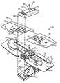
- FIG. 1is a perspective view of an ECG recording device and return mailer for returning the ECG recording device to a processing facility;
- FIG. 2is an exploded, perspective view of the ECG recording device of FIG. 1 ;
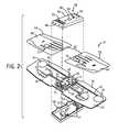
- FIG. 3is an exploded, perspective view of an alternative ECG recording device
- FIG. 4is a view showing collection of a fluid sample by an ECG recording device
- FIG. 5is a view illustrating positioning a subject's hands within an ECG recording device
- FIG. 6is a view illustrating positioning an ECG recording device on a subject's abdomen
- FIG. 7is a view illustrating communication of control units of an ECG recording device.
- FIG. 8is a high-level block diagram of a control circuit included as part of an ECG recording device.
- inventive arrangementswill be described in terms of cardiac monitoring equipment.
- inventive arrangementsare not limited in this regard.
- inventive arrangementsmay provide self-administering ECG examinations in patient-monitoring contexts, other contexts are also hereby contemplated, including various other consumer, industrial, radiological, and inspection systems, and/or the like.
- FIG. 1it depicts a portable, non-ambulatory, and non-invasive electrocardiogram (“ECG”) recording device 10 that can be used to monitor and/or record ECG waveforms from a patient (not shown), preferably at a location remote from the patient's physician's office, clinic, and/or other traditional ECG-equipped facility.
- the ECG recording device 10is dispensed, such as at a pharmacy and/or other outlet, for example, along with a return mailer 12 .
- the return mailer 12preferably contains a mailing address 14 and/or prepaid postage 16 .
- the return mailer 12also includes a bar code 17 and/or other similar tracking mechanism that can be used to identify the ECG recording device 10 when the ECG recording device 10 is returned to the mailing address 14 contained on the return mailer 12 .
- FIGS. 1-2illustrate a first embodiment of the ECG recording device 10 .
- the ECG recording device 10includes a base 18 , such as a flexible and/or semi-flexible base, such as formed from Mylar, extending on both sides of a control unit 19 centrally located thereabout.
- the base 18is flexible enough so as to conform to various body shapes and/or sizes, particularly as it is held against a subject's abdomen, as will be elaborated upon.
- the control unit 19includes an outer housing 48 that surrounds an internal control circuit 20 .
- the control circuit 20preferably includes a power source 22 , such as an ambient light receptor and/or battery, connected to a central processing unit (“CPU”) 24 and/or the like.
- the CPU 24is in electrical communication with a pair of first leads 26 and a pair of second leads 28 , each of which terminates at one or more respective contact pads 30 , 31 .
- the contact pads 30 , 31are each mounted on a top surface 32 of the base 18 .
- the base 18further includes a first sensor pad 34 and a second sensor pad 36 formed on a bottom surface 39 of the base 18 .
- the first sensor pad 34 and second sensor pad 36are electrically connected to the control circuit 20 by respective leads 40 , 42 .
- the control circuit 20further includes and/or is otherwise connected to a display 44 that allows the control circuit 20 to communicate messages to the patient.
- the control circuit 20further includes a push button 46 and/or the like that provides an input and/or output for the patient to communicate with the control circuit 20 .
- the control circuit 20is enclosed within the outer housing 48 , which further includes a top section 50 and opposing bottom section 52 .
- both the top section 50 and bottom section 52are formed from molded plastic and can include one or more interlocks 54 or the like that extend through one or more openings 55 formed in the base 18 to allow the top section 50 and the bottom section 52 to be secured to each other.
- the top section 50includes speaker openings 56 , a push button opening 58 , and/or a display window 60 , preferably in mating alignment with the control circuit 20 .
- the ECG recording device 10includes a first overlay 62 (e.g., right) and a second overlay 64 (e.g., left) that are each attachable to the base 18 to protect the control circuit 20 and leads 26 , 28 , 40 , and 42 , formed on the top surface 32 of the base 18 .
- a first overlay 62e.g., right
- a second overlay 64e.g., left
- both the first overlay 62 and second overlay 64are adhered to the base 18 using conventional techniques, such as an adhesive.
- the first overlay 62includes a graphic depiction 66 of a right hand of a patient while the second overlay 64 includes another graphic depiction 68 of a left hand of the patient.
- these graphic depictions 66 , 68serve as guides for positioning the patient's hands on the ECG recording device 10 .
- both the first overlay 62 and second overlay 64each include an elastic finger cuff 70 that engages a portion of the index finger or other of the respective right and left hands of the patient while recording an ECG signal.
- each finger cuff 70includes a pair of electrodes that contact opposite sides of the patient's index fingers.
- at least a portion of each finger cuff 70is made from a suitable electrically conductive material.
- the pair of electrodes within the finger cuffs 70contacts one of the contact pads 30 , 31 formed on the base 18 when the first overlay 62 and second overlay 64 are adhered to the base 18 . In this manner, electrical signals present on the skin of the patient can be detected and transferred to the CPU 24 through the first leads 26 and second leads 28 .
- first overlay 62 and second overlay 64are each shown including a finger cuff 70
- the finger cuffs 70could be replaced by tactile-sensing dry electrodes (not shown) formed on a top surface 65 of each of the overlays 62 , 64 .
- the electrodescould be contacted by the fingers of the patient's left and right hands during an ECG reading.
- the first leads 26 and second leads 28would be coupled to such sensing electrodes and deliver sensed electrical signals to the CPU 24 .
- FIG. 3also illustrates a second embodiment of the ECG recording device 10 .
- the ECG recording device 10uses eco-friendly packaging and components.
- the base 18can be formed from flexible, semi-flexible, foldable, rollable, and/or the like cotton fibers and cellulose paper, as compared to the Mylar base 18 previously described in FIGS. 1-2 .
- the leads 26 , 28 , 40 , and 42can be printed on the base 18 with electrically-conductive soy ink and/or the like on the top surface 32 of the base 18 .
- at least one or both of the first sensor pad 34 and second sensor pad 36can be likewise printed on the bottom surface 39 of the base 18 , again using electrically-conductive soy ink and/or the like.
- the outer housing 48 in the second embodiment in FIG. 3includes a cardboard top layer 72 and cardboard bottom layer 74 that protects the control circuit 20 .
- a cardboard spacer 76can also be mounted to the top surface 32 of the base 18 to provide the required spacing for the control circuit 20 .
- the first overlay 62 and second overlay 64are preferably formed from paper and include the finger cuffs 70 , which can be formed from elastic materials with embedded electrode leads.
- the electrode leads in each of the finger cuffs 70contact one of the contact pads 30 , 31 formed on the top surface 32 of the base 18 to relay the sensed signals to the control circuit 20 .
- the second embodiment shown thereinpreferably forms most or all of its other layers from cellulose (e.g., paper and/or cardboard and/or other recyclable materials and/or the like), while the circuitry is connected using the electrically-conductive soy ink and/or the like.
- the soluble cellulose materialcan separate from the electronic parts, such that the entire ECG recording device 10 , other than the control circuit 20 , can be re-used and/or otherwise recycled.
- the display 44is preferably operated to provide a visually recognizable indication to the patient or others of the status of a particular ECG reading, such as when an ECG session is required, when to start and/or stop an ECG session, how long to conduct a particular ECG session, a number of times an ECG session can be initiated using the ECG recording device 10 , and/or a quality measure of the strength or quality of a received ECG signal.
- the display 44can be used to indicate that the signal quality is sufficient and/or that the ECG reading is proceeding accordingly.
- the display 44could also be a LCD display or series of e.g. red-yellow-green indicator lights to signify the status of the ECG session. In such embodiments, the display 44 could change during the ECG reading to indicate the status thereof.
- the CPU 24could implement a counter (not shown) that can change after a successful ECG recording is taken and/or recorded using the ECG recording device 10 .
- a counterfor example, in a count-down counter, the counter could count down to zero (or a like threshold), and upon reaching same, indicate to the patient that no more ECG readings are required or obtainable using that particular configuration of the ECG recording device 10 .
- the ECG recording device 10can signal to the patient that the ECG recording device 10 should be returned to the healthcare facility and/or the like.
- the ECG recording device 10is placed into the return mailer 12 of FIG.
- the ECG recording device 10could also be returned to a pharmacy and/or other healthcare facility where it was received for such processing and/or other handling.
- FIG. 8it depicts a high-level block diagram of the control circuit 20 , which preferably includes an internal or otherwise self-contained power source 22 , such as an ambient light receptor and/or battery, which can power the internal components thereof (connections not shown).
- the CPU 24interacts with a memory 78 , which can be integrated with the base 18 or removable therefrom.
- the memory 78is removable from the base 18 , it can be returned to the central location in addition to, or instead of, the entire ECG recording device 10 for processing the collected ECG data.
- the CPU 24also preferably interacts with a user interface 80 , such as a tactile start button or other push button 46 , as well as an acquisition interface 82 .
- a user interface 80such as a tactile start button or other push button 46
- the contact pads 30 , 31are preferably in communication with the acquisition interface 82 , which can convert analog information received through the respective leads 26 , 28 into digital information that can be stored in the memory 78 .
- the acquisition interface 82can also receive analog information from the first sensor pad 34 and second sensor pad 36 through their respective leads 40 , 42 , which information can also be stored in the memory 78 after being converted into suitable digital form.
- the control circuit 20also includes an internal connector 84 that allows an external ECG processing system to be connected to the ECG recording device 10 once the ECG recording device 10 is returned to its specified location for analysis.
- the connector 84can also be utilized to program a number of desired ECG readings to be made by the ECG recording device 10 prior to returning the same, or downloading additional information, such as demographics and/or tracking information and/or the like, about the patient, to the ECG recording device 10 .
- the connector 84can implement technology such as “near field” or radio or infrared communications, such that it is not necessary to require actual physical connection to the ECG recording device 10 .
- the collected ECG datacan be transmitted to the ECG processing system wirelessly.
- the ECG recording device 10 with collected ECG datacan be sealed in a sterile plastic bag and then safely read by scanning the protected ECG recording device 10 using suitable wireless technology.
- the ECG recording device 10can also include a receptor, such a indentation 86 , for a sealable blood well, along with a small pin (not shown) used to draw blood from the finger of the patient.
- a receptorsuch as a indentation 86
- a small pin(not shown) used to draw blood from the finger of the patient.
- another input connector 88can also be provided within the outer housing 48 to provide a further connection point to the control circuit 20 , wherein, for example, a cable (not shown) with additional disposable leads (not shown) could be attached for obtaining additional information from the patient.
- additional leadscould allow, for example, screening of additional types of arrhythmic conditions, such as Brugada Syndrome, which requires leads V1, V2, and V3. Further, additional leads could also be utilized to detect acute myocardial infarction if, for example, a 12-lead reading was obtained. These additional leads could be standard ECG lead wires or a belt-style device that users could fit around the circumference of their chests to acquire the so-called “chest” leads of V1-V6, and/or other leads including those of a right side for a 15-lead ECG.
- the ECG recording device 10can also be preprogrammed to beep or the like when it is time, for example, to take an ECG reading. This would require including e.g. an audio device (not shown), such as a piezoelectric speaker or buzzer, within the control unit 19 , preferably operable in conjunction with the speaker openings 56 .
- an audio devicesuch as a piezoelectric speaker or buzzer
- inventive arrangementsfurther contemplate transmitting recorded ECG data back to a central receiving site without needing to mail back the ECG recording device 10 .
- further optional considerationscould include, for example, providing a speaker within the control unit 19 to allow for acoustically-driven transmissions.
- the userwould dial a telephone number from a telephone and place the phone mouthpiece over the speaker so that recorded data can be modulated at a normal voice frequency and demodulated at the central receiving site.
- a network connectioncould also be added to permit a network transfer of ECG data over a private or public network, such as the Internet, and then to the central site.
- datacould also be optionally encrypted by the ECG recording device 10 and/or other for data transmissions and/or the like.
- the ECG recording device 10In one use of the ECG recording device 10 , a patient picking up a prescription, such as from a pharmacy and/or the like, could be given the portable ECG recording device 10 , which can be pre-programmed to request a predetermined set of ECG readings from the patient at prescribed intervals based upon the patient's drug therapy, for example. In this embodiment, the ECG recording device would be intended to be used by the patient at home and/or other locations remote from traditional points-of-care.
- the patientmay first prick their finger with the pin included with the ECG recording device 10 and then deposit a blood sample within the indentation 86 shown in the figures, such as shown in FIG. 4 .
- the indentation 86can then be sealed to create a blood well such that genetic testing and/or other types of blood testing can be carried out on the blood sample within the well at a subsequent time. Multiple and/or other bodily fluids can also be received.
- each of the finger cuffs 70preferably includes a pair of electrodes that communicate with the control circuit 20 contained within the ECG recording device 10 .
- the display 44 and/or the likecan provide a status indication to the patient that the ECG recording device 10 is ready to operate and/or operating to record an ECG signal.
- the display 44can indicate that the reading is finished, prompting the patient to remove his or her hands from the finger cuffs 70 and/or remove the ECG recording device 10 from the patient's abdomen 92 .
- a counter within the control circuit 20can change until the counter reaches a pre-determined threshold, indicating no additional ECG readings are required.
- the ECG recording device 10can communicate to the patient either through the display 44 or through audible signals 94 transmitted by a speaker contained within the control unit 19 .
- the patientis preferably prompted to return the ECG recording device 10 , such as by U.S. mail and/or international mail and/or the like, using the return mailer 12 , to a central location for further analysis and/or processing. If desired, the patient can be notified when the central location receives the patient's ECG recording device 10 .
- the ECG data stored in the control circuit 20can be read, analyzed, and/or otherwise processed, and the patient and/or patient's physician and/or the like can be advised of the ECG results.
- the entire ECG recording device 10can be disposed of and/or otherwise recycled. In the case of the embodiment shown in FIG. 3 , for example, the entire ECG recording device 10 , other than the control circuit 20 , can also be reused and/or recycled.
- the system that reads the ECG data and/or programs the ECG recording device 10can also be programmed to call the patient on appropriate days to remind them to perform their ECG recording.
- the patientmay need to register at a secure website, for example. Registering at the website could also allow the patient to enter demographic and/or other health information about the patient, as well as any responses to other questions and/or provide other feedback.
- ECG recording device 10can be used with prescribed medication, it can also be provided in retail stores to allow individual consumers to acquire ECG data, which clinicians can then use to screen for cardiac problems.
- the ECG recording device 10can also be provided in schools and/or other community establishments and/or the like to enable ECG screenings, and it may also be useful in insurance evaluations and/or other applications as well.
- a portable, non-ambulatory, non-invasive, disposable ECG recording device 10which can be customized and operated in a simple matter by a patient undergoing a prescribed drug therapy.
- the devicecan also be designed to be produced in quantities for large-scale use at low cost and/or intended to convey time-delayed data retrospectively, and various components thereof can be branded and/or left anonymous, as needed and/or desired.
- the packaging of the ECG recording device 10can be integrated for shipment thereof to the central location for analyzing the ECG recordings and/or reporting to the patient and/or a clinician and/or the like.
- the ECG recording device 10can also be used in high-risk infection environments, without, for example, needing to clean and disinfect the same after every use.
Landscapes
- Health & Medical Sciences (AREA)
- Life Sciences & Earth Sciences (AREA)
- Engineering & Computer Science (AREA)
- Molecular Biology (AREA)
- Animal Behavior & Ethology (AREA)
- Pathology (AREA)
- Physics & Mathematics (AREA)
- Biomedical Technology (AREA)
- Heart & Thoracic Surgery (AREA)
- Medical Informatics (AREA)
- Veterinary Medicine (AREA)
- Surgery (AREA)
- Biophysics (AREA)
- General Health & Medical Sciences (AREA)
- Public Health (AREA)
- Hematology (AREA)
- Cardiology (AREA)
- Immunology (AREA)
- Vascular Medicine (AREA)
- Microelectronics & Electronic Packaging (AREA)
- Dermatology (AREA)
- Measurement And Recording Of Electrical Phenomena And Electrical Characteristics Of The Living Body (AREA)
- Measuring And Recording Apparatus For Diagnosis (AREA)
Abstract
Description
Claims (33)
Priority Applications (4)
| Application Number | Priority Date | Filing Date | Title |
|---|---|---|---|
| US11/610,995US8594771B2 (en) | 2005-12-28 | 2006-12-14 | Devices and methods for self-administered ECG examinations |
| JP2007311850AJP5207717B2 (en) | 2006-12-14 | 2007-12-03 | Equipment for self-managed ECG inspection |
| DE102007060551ADE102007060551A1 (en) | 2006-12-14 | 2007-12-13 | Electrocardiogram recording device for use in e.g. school has electrode assembly engaged with mailable base to receive one or more electrocardiogram signals from subject during self-administered electrocardiogram examination |
| CN200710306876.9ACN101254097B (en) | 2006-12-14 | 2007-12-14 | Devices and methods for self-administered ecg examinations |
Applications Claiming Priority (2)
| Application Number | Priority Date | Filing Date | Title |
|---|---|---|---|
| US11/319,640US20070149886A1 (en) | 2005-12-28 | 2005-12-28 | ECG recording device and method of use |
| US11/610,995US8594771B2 (en) | 2005-12-28 | 2006-12-14 | Devices and methods for self-administered ECG examinations |
Related Parent Applications (1)
| Application Number | Title | Priority Date | Filing Date |
|---|---|---|---|
| US11/319,640Continuation-In-PartUS20070149886A1 (en) | 2005-12-28 | 2005-12-28 | ECG recording device and method of use |
Publications (2)
| Publication Number | Publication Date |
|---|---|
| US20070149888A1 US20070149888A1 (en) | 2007-06-28 |
| US8594771B2true US8594771B2 (en) | 2013-11-26 |
Family
ID=39399991
Family Applications (1)
| Application Number | Title | Priority Date | Filing Date |
|---|---|---|---|
| US11/610,995Active2028-01-07US8594771B2 (en) | 2005-12-28 | 2006-12-14 | Devices and methods for self-administered ECG examinations |
Country Status (4)
| Country | Link |
|---|---|
| US (1) | US8594771B2 (en) |
| JP (1) | JP5207717B2 (en) |
| CN (1) | CN101254097B (en) |
| DE (1) | DE102007060551A1 (en) |
Cited By (3)
| Publication number | Priority date | Publication date | Assignee | Title |
|---|---|---|---|---|
| US20160095527A1 (en)* | 2014-10-01 | 2016-04-07 | Google Inc. | Electrocardiography device for garments |
| WO2020167154A1 (en)* | 2019-02-13 | 2020-08-20 | Vlaskalic Srdjan | Pocket-size folding device with integrated electrodes for recording, processing and transmission with three ecg leads |
| US20210244336A1 (en)* | 2010-06-08 | 2021-08-12 | Alivecor, Inc. | Medical packaging with integrated electrocardiogram sensor |
Families Citing this family (14)
| Publication number | Priority date | Publication date | Assignee | Title |
|---|---|---|---|---|
| US20120116176A1 (en)* | 2010-11-04 | 2012-05-10 | The Cleveland Clinic Foundation | Handheld boifeedback device and method for self-regulating at least one physiological state of a subject |
| GB2503055B (en)* | 2012-04-04 | 2018-08-29 | Cardiocity Ltd | Heart monitoring apparatus |
| US9332919B2 (en) | 2011-04-04 | 2016-05-10 | Cardiocity Limited | Heart monitoring apparatus |
| GB2489704B (en)* | 2011-04-04 | 2013-06-12 | Cardiocity Ltd | ECG mat |
| CN102327114B (en)* | 2011-06-07 | 2013-06-12 | 李钢坤 | Electrode protection device of draper-type electronic monitoring terminal |
| TWM432391U (en)* | 2012-01-04 | 2012-07-01 | Vicon Healthcare Int Inc | An improved device for collecting a physiological signal |
| CN103300843A (en)* | 2012-03-09 | 2013-09-18 | 深圳市倍泰健康测量分析技术有限公司 | Cell phone protection cover and physical parameter detector thereof |
| WO2014038212A1 (en)* | 2012-09-10 | 2014-03-13 | パナソニック株式会社 | Electronic machine, information processing device, information processing method, and program |
| TWI539931B (en)* | 2014-01-03 | 2016-07-01 | 緯創資通股份有限公司 | Electrocardiography detecting method and device thereof |
| ES2828723T3 (en) | 2015-02-27 | 2021-05-27 | Icentia Inc | Wearable Physiological Data Acquisition Device and Methods of Using It |
| RU169652U1 (en)* | 2015-09-14 | 2017-03-28 | Общество с ограниченной ответственностью "Найтек" | PORTABLE DEVICE FOR REGISTRATION OF ELECTROCARDIOGRAMS |
| US11786744B2 (en) | 2018-03-16 | 2023-10-17 | Zoll Medical Corporation | Wearable medical device for continuous heart monitoring with intermittent additional signal data provided via one or more touch-sensitive electrodes |
| RU2746036C1 (en)* | 2020-08-11 | 2021-04-06 | Валерий Геннадьевич Мужиков | Method for quantitative assessment of acupuncture channel activity, system and module for its implementation |
| US20230026212A1 (en)* | 2021-06-25 | 2023-01-26 | Spaulding Medical, LLC | Electrocardiogram electrode application system |
Citations (31)
| Publication number | Priority date | Publication date | Assignee | Title |
|---|---|---|---|---|
| US41804A (en) | 1864-03-01 | woolworth | ||
| FR2519856A1 (en) | 1982-01-20 | 1983-07-22 | Micro Med | Portable ECG appts. with memory utilisable by patient - has amplifier converters semiconductor memory and control circuit in box with external electrodes |
| JPS5944242A (en) | 1982-08-05 | 1984-03-12 | コントロン・ホ−ルデイング・アクチエンゲゼルシヤフト | Indivisual electrocardiograph recorder |
| US4531527A (en)* | 1982-04-23 | 1985-07-30 | Survival Technology, Inc. | Ambulatory monitoring system with real time analysis and telephone transmission |
| US5191891A (en)* | 1991-09-10 | 1993-03-09 | Ralin, Inc. | Portable ECG monitor/recorder |
| WO1994001040A1 (en) | 1992-07-13 | 1994-01-20 | Hertford Medical Limited | Heart monitoring apparatus |
| JPH07275217A (en) | 1994-04-11 | 1995-10-24 | Casio Comput Co Ltd | Electrocardiograph |
| JPH09117420A (en) | 1995-08-01 | 1997-05-06 | Arrigo Castelli | Pocket equipment that detects especially electric biologicalsignal that is electrocardiogram signal |
| JP2000083907A (en) | 1998-09-10 | 2000-03-28 | Matsushita Electric Ind Co Ltd | Electronic first aid kit and program recording medium |
| US6075150A (en) | 1998-01-26 | 2000-06-13 | Cv Therapeutics, Inc. | α-ketoamide inhibitors of 20S proteasome |
| JP2001149327A (en) | 2000-10-27 | 2001-06-05 | Pioneer Electronic Corp | Biological measuring device |
| US6244462B1 (en) | 1997-02-19 | 2001-06-12 | Cypak Ab | Medicament dispense sensing device |
| JP2001245863A (en) | 2000-03-06 | 2001-09-11 | Yutaka Totsuka | Card-type electrocardiograph |
| US6301502B1 (en) | 1997-03-07 | 2001-10-09 | Cardiac Science Inc. | Defibrillation system |
| JP2002501775A (en) | 1998-01-28 | 2002-01-22 | サニマト・ディフュージョン エス アー | ECG recording device |
| JP2002045343A (en) | 2000-08-01 | 2002-02-12 | Sanyo Electric Co Ltd | Vital sensor |
| JP2003070759A (en) | 2001-09-07 | 2003-03-11 | Toshio Asai | Portable electrocardiograph and methods of wearing and using the same |
| US6558320B1 (en) | 2000-01-20 | 2003-05-06 | Medtronic Minimed, Inc. | Handheld personal data assistant (PDA) with a medical device and method of using the same |
| US20030109772A1 (en)* | 2000-10-06 | 2003-06-12 | Mills Alexander K. | Method for noninvasive continuous determination of physiologic characteristics |
| US6580943B2 (en)* | 2000-06-29 | 2003-06-17 | Polar Electro Oy | ECG electrode structure and method for measuring ECG signal from a person in water |
| US20030167075A1 (en) | 2001-08-31 | 2003-09-04 | Randall Fincke | Automated external defibrillator (AED) system |
| US6701183B2 (en) | 2001-04-06 | 2004-03-02 | Lechnolgies, Llc | Long term atrial fibrillation monitor |
| US6730025B1 (en) | 1998-11-03 | 2004-05-04 | Harry Louis Platt | Hand held physiological signal acquisition device |
| CN2659055Y (en) | 2003-10-17 | 2004-11-24 | 葛武 | Mobile phone with electrocardio gram, blood pressure and temp. monitoring function |
| JP2005000468A (en) | 2003-06-13 | 2005-01-06 | Omron Healthcare Co Ltd | Electrocardiograph and its displaying method |
| US20050010087A1 (en)* | 2003-01-07 | 2005-01-13 | Triage Data Networks | Wireless, internet-based medical-diagnostic system |
| WO2005018447A1 (en) | 2003-08-20 | 2005-03-03 | Bosko Bojovic | Apparatus and method for cordless recording and telecommunication transmission of three special ecg leads and their processing |
| WO2006034291A2 (en) | 2004-09-21 | 2006-03-30 | Vivometrics, Inc. | Inductive plethysmographic sensors, monitors, and apparel |
| JP2006247075A (en) | 2005-03-10 | 2006-09-21 | Masafumi Matsumura | Bioelectric signal measuring device, and electrode apparatus |
| US20070100213A1 (en)* | 2005-10-27 | 2007-05-03 | Dossas Vasilios D | Emergency medical diagnosis and communications device |
| US7236818B2 (en) | 2001-10-12 | 2007-06-26 | Ge Medical Systems Information Technologies, Inc. | Handheld interpreting electrocardiograph |
- 2006
- 2006-12-14USUS11/610,995patent/US8594771B2/enactiveActive
- 2007
- 2007-12-03JPJP2007311850Apatent/JP5207717B2/enactiveActive
- 2007-12-13DEDE102007060551Apatent/DE102007060551A1/ennot_activeCeased
- 2007-12-14CNCN200710306876.9Apatent/CN101254097B/ennot_activeExpired - Fee Related
Patent Citations (36)
| Publication number | Priority date | Publication date | Assignee | Title |
|---|---|---|---|---|
| US41804A (en) | 1864-03-01 | woolworth | ||
| FR2519856A1 (en) | 1982-01-20 | 1983-07-22 | Micro Med | Portable ECG appts. with memory utilisable by patient - has amplifier converters semiconductor memory and control circuit in box with external electrodes |
| US4531527A (en)* | 1982-04-23 | 1985-07-30 | Survival Technology, Inc. | Ambulatory monitoring system with real time analysis and telephone transmission |
| JPS5944242A (en) | 1982-08-05 | 1984-03-12 | コントロン・ホ−ルデイング・アクチエンゲゼルシヤフト | Indivisual electrocardiograph recorder |
| US5191891A (en)* | 1991-09-10 | 1993-03-09 | Ralin, Inc. | Portable ECG monitor/recorder |
| WO1994001040A1 (en) | 1992-07-13 | 1994-01-20 | Hertford Medical Limited | Heart monitoring apparatus |
| JPH07275217A (en) | 1994-04-11 | 1995-10-24 | Casio Comput Co Ltd | Electrocardiograph |
| JPH09117420A (en) | 1995-08-01 | 1997-05-06 | Arrigo Castelli | Pocket equipment that detects especially electric biologicalsignal that is electrocardiogram signal |
| US5713365A (en) | 1995-08-01 | 1998-02-03 | Castelli; Arrigo | Pocket instrument for detecting an electric biological signal, in particular an electrocardiographic signal |
| US6244462B1 (en) | 1997-02-19 | 2001-06-12 | Cypak Ab | Medicament dispense sensing device |
| US6301502B1 (en) | 1997-03-07 | 2001-10-09 | Cardiac Science Inc. | Defibrillation system |
| US6075150A (en) | 1998-01-26 | 2000-06-13 | Cv Therapeutics, Inc. | α-ketoamide inhibitors of 20S proteasome |
| CN1289340A (en) | 1998-01-26 | 2001-03-28 | Cv治疗公司 | 20S proteasome alpha-ketoamide inhibitor |
| US6363274B1 (en)* | 1998-01-28 | 2002-03-26 | Sanimat Diffusion S.A. | Apparatus for recording an electrocardiogram |
| JP2002501775A (en) | 1998-01-28 | 2002-01-22 | サニマト・ディフュージョン エス アー | ECG recording device |
| JP2000083907A (en) | 1998-09-10 | 2000-03-28 | Matsushita Electric Ind Co Ltd | Electronic first aid kit and program recording medium |
| US20020115912A1 (en) | 1998-09-10 | 2002-08-22 | Kyoko Muraki | Electronic first aid kit, medium and information set |
| US6800059B2 (en) | 1998-09-10 | 2004-10-05 | Matsushita Electric Industrial Co., Ltd. | Vital sign box, medium, and information aggregation |
| US6730025B1 (en) | 1998-11-03 | 2004-05-04 | Harry Louis Platt | Hand held physiological signal acquisition device |
| US6558320B1 (en) | 2000-01-20 | 2003-05-06 | Medtronic Minimed, Inc. | Handheld personal data assistant (PDA) with a medical device and method of using the same |
| JP2001245863A (en) | 2000-03-06 | 2001-09-11 | Yutaka Totsuka | Card-type electrocardiograph |
| US6580943B2 (en)* | 2000-06-29 | 2003-06-17 | Polar Electro Oy | ECG electrode structure and method for measuring ECG signal from a person in water |
| JP2002045343A (en) | 2000-08-01 | 2002-02-12 | Sanyo Electric Co Ltd | Vital sensor |
| US20030109772A1 (en)* | 2000-10-06 | 2003-06-12 | Mills Alexander K. | Method for noninvasive continuous determination of physiologic characteristics |
| JP2001149327A (en) | 2000-10-27 | 2001-06-05 | Pioneer Electronic Corp | Biological measuring device |
| US6701183B2 (en) | 2001-04-06 | 2004-03-02 | Lechnolgies, Llc | Long term atrial fibrillation monitor |
| US20030167075A1 (en) | 2001-08-31 | 2003-09-04 | Randall Fincke | Automated external defibrillator (AED) system |
| JP2003070759A (en) | 2001-09-07 | 2003-03-11 | Toshio Asai | Portable electrocardiograph and methods of wearing and using the same |
| US7236818B2 (en) | 2001-10-12 | 2007-06-26 | Ge Medical Systems Information Technologies, Inc. | Handheld interpreting electrocardiograph |
| US20050010087A1 (en)* | 2003-01-07 | 2005-01-13 | Triage Data Networks | Wireless, internet-based medical-diagnostic system |
| JP2005000468A (en) | 2003-06-13 | 2005-01-06 | Omron Healthcare Co Ltd | Electrocardiograph and its displaying method |
| WO2005018447A1 (en) | 2003-08-20 | 2005-03-03 | Bosko Bojovic | Apparatus and method for cordless recording and telecommunication transmission of three special ecg leads and their processing |
| CN2659055Y (en) | 2003-10-17 | 2004-11-24 | 葛武 | Mobile phone with electrocardio gram, blood pressure and temp. monitoring function |
| WO2006034291A2 (en) | 2004-09-21 | 2006-03-30 | Vivometrics, Inc. | Inductive plethysmographic sensors, monitors, and apparel |
| JP2006247075A (en) | 2005-03-10 | 2006-09-21 | Masafumi Matsumura | Bioelectric signal measuring device, and electrode apparatus |
| US20070100213A1 (en)* | 2005-10-27 | 2007-05-03 | Dossas Vasilios D | Emergency medical diagnosis and communications device |
Non-Patent Citations (10)
| Title |
|---|
| "Ecg@home." HealthFrontier-web-based & wireless ECG/EKG cardiology. http://www.healthfrontier.com/Products/product-detail.cfm?productid=1, Dec. 14, 2006, p. 1-4. |
| http://www.dcbiomed.com/web/hanecg4.htm. |
| http://www.healthfrontier.com/Products/product-detail.cfm?productid=1. |
| http://www.lifesynccorp.com. |
| http://www.winhealth.co.uk/ECG.htm. |
| Office Action from corresponding U.S. Appl. No. 11/319,640, dated Jun. 25, 2008. |
| Search Report and Written Opinion from corresponding EP Application No. 06126333.1, dated Aug. 13, 2007. |
| Unofficial English translation of JP Office Action from corresponding JP Application No. 2006-349662, dated Mar. 27, 2012. |
| Unofficial English translation of JP Office Action from corresponding JP Application No. 2007-311850, dated Jul. 10, 2012. |
| Unofficial Translation of JPO Notice of Allowance from corresponding JP Application 2007-311850 dated Jan. 22, 2013. |
Cited By (6)
| Publication number | Priority date | Publication date | Assignee | Title |
|---|---|---|---|---|
| US20210244336A1 (en)* | 2010-06-08 | 2021-08-12 | Alivecor, Inc. | Medical packaging with integrated electrocardiogram sensor |
| US11872046B2 (en)* | 2010-06-08 | 2024-01-16 | Alivecor, Inc. | Medical packaging with integrated electrocardiogram sensor |
| US20160095527A1 (en)* | 2014-10-01 | 2016-04-07 | Google Inc. | Electrocardiography device for garments |
| US9662030B2 (en)* | 2014-10-01 | 2017-05-30 | Verily Life Sciences Llc | Electrocardiography device for garments |
| WO2020167154A1 (en)* | 2019-02-13 | 2020-08-20 | Vlaskalic Srdjan | Pocket-size folding device with integrated electrodes for recording, processing and transmission with three ecg leads |
| US11406311B2 (en) | 2019-02-13 | 2022-08-09 | Heartpal Tech Doo | Pocket-size folding device with integrated electrodes for recording, processing and transmission with three ECG leads |
Also Published As
| Publication number | Publication date |
|---|---|
| DE102007060551A1 (en) | 2008-06-19 |
| JP5207717B2 (en) | 2013-06-12 |
| US20070149888A1 (en) | 2007-06-28 |
| CN101254097B (en) | 2014-01-01 |
| CN101254097A (en) | 2008-09-03 |
| JP2008149127A (en) | 2008-07-03 |
Similar Documents
| Publication | Publication Date | Title |
|---|---|---|
| US8594771B2 (en) | Devices and methods for self-administered ECG examinations | |
| EP1803392B1 (en) | ECG recording device and method of use | |
| US20140073979A1 (en) | eCard ECG Monitor | |
| JP5203973B2 (en) | Non-invasive cardiac monitoring device and method of using continuously recorded cardiac data | |
| US8688189B2 (en) | Programmable ECG sensor patch | |
| EP0553372B1 (en) | Method and system for monitoring vital signs | |
| US8773258B2 (en) | Data collection module for a physiological data collection system | |
| US8626262B2 (en) | Physiological data collection system | |
| CN106419859A (en) | Wearable device for pulse reading | |
| EP1784126A2 (en) | Heart disease detection patch | |
| EP1933705A1 (en) | Ear-thermometer with ear identification | |
| JP2012500698A (en) | Method and system for supplying a patient identification beacon to a patient wearable sensor | |
| WO2008005015A1 (en) | Programmable ecg sensor patch | |
| GB2523880A (en) | Sensor | |
| Hunt et al. | Devices used for self-measurement of blood pressure: revised statement of the National High Blood Pressure Education Program | |
| KR20010096186A (en) | Integral medical diagnosis apparatus | |
| CN111543980A (en) | Electrocardiogram electrode device, electrocardiogram capturing device and electrocardiogram checking system | |
| CN100484464C (en) | Interactive device for home health care | |
| CN214157296U (en) | A family health all-in-one machine | |
| CN218474594U (en) | Wireless monitoring device | |
| WO2018001389A1 (en) | Implantable monitor | |
| CN213488862U (en) | Electrocardiogram electrode device and electrocardiogram capture device | |
| CN202223224U (en) | Portable electrocardiogram monitoring device and electrocardiogram monitoring system | |
| KR200202683Y1 (en) | Apparatus for collectting a singal of living body | |
| JPH0529686Y2 (en) |
Legal Events
| Date | Code | Title | Description |
|---|---|---|---|
| AS | Assignment | Owner name:GENERAL ELECTRIC COMPANY, NEW YORK Free format text:ASSIGNMENT OF ASSIGNORS INTEREST;ASSIGNORS:KOHLS, MARK ROBERT;ALME, SARAH BETH;VALIGA, RICHARD ANDREW;AND OTHERS;SIGNING DATES FROM 20061215 TO 20070131;REEL/FRAME:018850/0655 Owner name:GENERAL ELECTRIC COMPANY, NEW YORK Free format text:ASSIGNMENT OF ASSIGNORS INTEREST;ASSIGNORS:KOHLS, MARK ROBERT;ALME, SARAH BETH;VALIGA, RICHARD ANDREW;AND OTHERS;REEL/FRAME:018850/0655;SIGNING DATES FROM 20061215 TO 20070131 | |
| AS | Assignment | Owner name:GENERAL ELECTRIC COMPANY, NEW YORK Free format text:CORRECTIVE ASSIGNMENT TO CORRECT THE MIDDLE NAME SPELLING FOR ONE OF THE INVENTOR'S, ON A DOCUMENT PREVIOUSLY RECORDED ON REEL 018850, FRAME 0655;ASSIGNORS:KOHLS, MARK ROBERT;ALME, SARAH BETH;VALIGA, RICHARD ANDREW;AND OTHERS;REEL/FRAME:018928/0709;SIGNING DATES FROM 20061215 TO 20070219 Owner name:GENERAL ELECTRIC COMPANY, NEW YORK Free format text:CORRECTIVE ASSIGNMENT TO CORRECT THE MIDDLE NAME SPELLING FOR ONE OF THE INVENTOR'S, ON A DOCUMENT PREVIOUSLY RECORDED ON REEL 018850, FRAME 0655. ASSIGNOR(S) HEREBY CONFIRMS THE CORRECT SPELLING OF ASSIGNOR;ASSIGNORS:KOHLS, MARK ROBERT;ALME, SARAH BETH;VALIGA, RICHARD ANDREW;AND OTHERS;SIGNING DATES FROM 20061215 TO 20070219;REEL/FRAME:018928/0709 | |
| STCF | Information on status: patent grant | Free format text:PATENTED CASE | |
| CC | Certificate of correction | ||
| FPAY | Fee payment | Year of fee payment:4 | |
| MAFP | Maintenance fee payment | Free format text:PAYMENT OF MAINTENANCE FEE, 8TH YEAR, LARGE ENTITY (ORIGINAL EVENT CODE: M1552); ENTITY STATUS OF PATENT OWNER: LARGE ENTITY Year of fee payment:8 | |
| MAFP | Maintenance fee payment | Free format text:PAYMENT OF MAINTENANCE FEE, 12TH YEAR, LARGE ENTITY (ORIGINAL EVENT CODE: M1553); ENTITY STATUS OF PATENT OWNER: LARGE ENTITY Year of fee payment:12 | |
| AS | Assignment | Owner name:GE PRECISION HEALTHCARE LLC, WISCONSIN Free format text:NUNC PRO TUNC ASSIGNMENT;ASSIGNOR:GENERAL ELECTRIC COMPANY;REEL/FRAME:071225/0218 Effective date:20250505 |