US8594770B2 - Multispectral detection and presentation of an object's characteristics - Google Patents
Multispectral detection and presentation of an object's characteristicsDownload PDFInfo
- Publication number
- US8594770B2 US8594770B2US12/925,166US92516610AUS8594770B2US 8594770 B2US8594770 B2US 8594770B2US 92516610 AUS92516610 AUS 92516610AUS 8594770 B2US8594770 B2US 8594770B2
- Authority
- US
- United States
- Prior art keywords
- light
- wavelengths
- laser
- photo
- scan
- Prior art date
- Legal status (The legal status is an assumption and is not a legal conclusion. Google has not performed a legal analysis and makes no representation as to the accuracy of the status listed.)
- Active, expires
Links
Images


Classifications
- A—HUMAN NECESSITIES
- A61—MEDICAL OR VETERINARY SCIENCE; HYGIENE
- A61B—DIAGNOSIS; SURGERY; IDENTIFICATION
- A61B5/00—Measuring for diagnostic purposes; Identification of persons
- A61B5/0059—Measuring for diagnostic purposes; Identification of persons using light, e.g. diagnosis by transillumination, diascopy, fluorescence
- A61B5/0075—Measuring for diagnostic purposes; Identification of persons using light, e.g. diagnosis by transillumination, diascopy, fluorescence by spectroscopy, i.e. measuring spectra, e.g. Raman spectroscopy, infrared absorption spectroscopy
- A—HUMAN NECESSITIES
- A61—MEDICAL OR VETERINARY SCIENCE; HYGIENE
- A61B—DIAGNOSIS; SURGERY; IDENTIFICATION
- A61B5/00—Measuring for diagnostic purposes; Identification of persons
- A61B5/0059—Measuring for diagnostic purposes; Identification of persons using light, e.g. diagnosis by transillumination, diascopy, fluorescence
- A61B5/0077—Devices for viewing the surface of the body, e.g. camera, magnifying lens
- A—HUMAN NECESSITIES
- A61—MEDICAL OR VETERINARY SCIENCE; HYGIENE
- A61B—DIAGNOSIS; SURGERY; IDENTIFICATION
- A61B5/00—Measuring for diagnostic purposes; Identification of persons
- A61B5/0059—Measuring for diagnostic purposes; Identification of persons using light, e.g. diagnosis by transillumination, diascopy, fluorescence
- A61B5/0082—Measuring for diagnostic purposes; Identification of persons using light, e.g. diagnosis by transillumination, diascopy, fluorescence adapted for particular medical purposes
- A61B5/0088—Measuring for diagnostic purposes; Identification of persons using light, e.g. diagnosis by transillumination, diascopy, fluorescence adapted for particular medical purposes for oral or dental tissue
- A—HUMAN NECESSITIES
- A61—MEDICAL OR VETERINARY SCIENCE; HYGIENE
- A61B—DIAGNOSIS; SURGERY; IDENTIFICATION
- A61B5/00—Measuring for diagnostic purposes; Identification of persons
- A61B5/48—Other medical applications
- A61B5/4887—Locating particular structures in or on the body
- A—HUMAN NECESSITIES
- A61—MEDICAL OR VETERINARY SCIENCE; HYGIENE
- A61B—DIAGNOSIS; SURGERY; IDENTIFICATION
- A61B5/00—Measuring for diagnostic purposes; Identification of persons
- A61B5/48—Other medical applications
- A61B5/4887—Locating particular structures in or on the body
- A61B5/489—Blood vessels
- A—HUMAN NECESSITIES
- A61—MEDICAL OR VETERINARY SCIENCE; HYGIENE
- A61B—DIAGNOSIS; SURGERY; IDENTIFICATION
- A61B90/00—Instruments, implements or accessories specially adapted for surgery or diagnosis and not covered by any of the groups A61B1/00 - A61B50/00, e.g. for luxation treatment or for protecting wound edges
- A61B90/36—Image-producing devices or illumination devices not otherwise provided for
- A61B2090/364—Correlation of different images or relation of image positions in respect to the body
- A61B2090/366—Correlation of different images or relation of image positions in respect to the body using projection of images directly onto the body
- A—HUMAN NECESSITIES
- A61—MEDICAL OR VETERINARY SCIENCE; HYGIENE
- A61M—DEVICES FOR INTRODUCING MEDIA INTO, OR ONTO, THE BODY; DEVICES FOR TRANSDUCING BODY MEDIA OR FOR TAKING MEDIA FROM THE BODY; DEVICES FOR PRODUCING OR ENDING SLEEP OR STUPOR
- A61M5/00—Devices for bringing media into the body in a subcutaneous, intra-vascular or intramuscular way; Accessories therefor, e.g. filling or cleaning devices, arm-rests
- A61M5/42—Devices for bringing media into the body in a subcutaneous, intra-vascular or intramuscular way; Accessories therefor, e.g. filling or cleaning devices, arm-rests having means for desensitising skin, for protruding skin to facilitate piercing, or for locating point where body is to be pierced
- A61M5/427—Locating point where body is to be pierced, e.g. vein location means using ultrasonic waves, injection site templates
Definitions
- the present inventionrelates to improvements in multispectral imaging for determining the characteristics of an objects, and more particularly to improvements which are capable of providing imaging of internal structure through trans-illumination apparatus and techniques.
- the human visual systemis able to detect light in a range of wavelengths that are typically described as “visible light.” The longest wavelengths detected are red, the mid range is green and shortest wavelengths are blue. Long wavelength light such as infrared and short wavelength light such as ultraviolet are invisible to the human eye. The characteristics of an object that we can determine with the unaided eye are limited to those that can be detected in this spectrum. Furthermore, the trichromatic system used by the eye is broadband in nature and cannot see narrowband artifacts such as would be seen by a spectrophotometer.
- the AccuVein AV300detects a pattern of absorption and reflection in the infrared and re-projects that pattern as red. Given that hemoglobin absorbs infrared light to a greater degree than the surrounding tissue, the projected pattern can be used by a medical practitioner to identify the position of a vein to be used for venipuncture.
- the lightis captured and the processed image is displayed on a remote screen such as an LCD panel or through an eyepiece that is in line with the object.
- contrast enhancement productsact as color shifters. Just as the human eye would detect variations in absorption and reflection in the three colors it can see (red, green and blue), these contrast enhancers detect the variations at wavelengths outside the visible spectrum and display the corresponding pattern inside the visible spectrum.
- the inventioncan be further enhanced by combining some or all of these techniques to detect and project different characteristics of the object being scanned and projecting them back on the object.
- FIG. 1shows the different absorption spectrum for deoxygenated human hemoglobin and for oxygenated hemoglobin.
- FIG. 2shows a laser camera system having multiple frequency lasers for multispectral imaging applications.
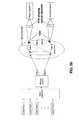
- FIG. 3Ashows the laser camera system of FIG. 2 , but with a pair of photo detectors positioned to avoid laser light reflected from the skin surface, and positioned for transillumination of an internal structure.
- FIG. 3Bshows the laser camera system of FIG. 3 , but where the photo detectors are configured to have their field-of-view restricted by optical elements, to areas of the skin of the body part that are not directly illuminated by the laser light.
- FIG. 4shows a 5 ⁇ 5 array of photo detectors.
- FIG. 5shows a photo detector ring with a circular array of photo detectors arranged around the body part to be penetrated to detect laser light scattered from an inner structure.
- FIG. 6shows a block diagram of a closed loop projection system capable of capturing images with high dynamic range.
- FIG. 7shows a flow chart illustrating the functioning of the system of FIG. 6 .
- FIG. 8shows a laser camera system for capturing images of a tooth.
- FIG. 9Ashows a color filter which limits the response of the photo detector.
- FIG. 9Bshows a first filter and a second filter being used to limit the response of the photo detector.
- FIG. 9Cshows the first and second filters of FIG. 9B with a pair of electronic shutters also being used to electro-optically limit the response of the photo detector.
- FIG. 9Dshows a grating being used to transmit light to three different color-resolved detectors.
- a laser cameraworks by emitting one or more laser beams and moving those beams in a pattern such that the beams cross over the area of an object of which an image is to be captured.
- a photo detector element in the cameracaptures the changes in light reflected from the object and uses that light change to create an image of the observed object.
- objectshould be read in this explanation as an object or as a group of objects (e.g., an apple or a still life that includes an apple).
- the pattern in which the beam is movedis unimportant as long as the position at which it strikes the object can be determined either directly or inferentially. Examples of patterns that can be used include raster and lissajous.
- the AccuVein AV300is a laser camera system that uses a single infrared laser scanned over the object (in this case the human body) to determine the position of hemoglobin as a proxy for the position of a vein.
- the deviceuses the general characteristic of hemoglobin in that it absorbs infrared light to a greater degree than surrounding tissue. As seen in FIG. 1 , there is a slightly different absorption spectrum for deoxygenated hemoglobin (as would be found in veins) and oxygenated hemoglobin (as would be found in arteries).
- the inventioncould detect the difference between a vein and an artery.
- the user interfacecould then use one or more of several techniques to indicate the type of hemoglobin detected.
- infrared wavelengthsto detect different types of hemoglobin are used for this illustrative example, there are many characteristics well know in the art that can be determined by the absorption spectrum of an object that the invention would be equally suited to.
- One embodiment of the inventionuses a one or more data capture techniques as discussed previously and provides user feedback by re-projecting a re-colored image back on to the area being scanned. Since it is possible for one or more of the wavelengths of light being captured to overlap with the wavelengths of light being projected it is necessary to implement one or more techniques to prevent the projected light from being confused with the detected light.
- asymmetrical detection and projectionallows a balance between the amount of time that might be needed for capture and the processing the captured information and the need to have a sufficiently high projection rate to provide a good user experience.
- Other asymmetrical combinationsare possible.
- An alternative embodiment of the inventionis one in which diffuse light of one or more wavelengths is emitted and then reflected by the object under study.
- a digital camera using technologysuch as CMOS or CCD sensors captures an image of the object being studied to determine the reflection/absorption spectrum of the object.
- the spectral characteristics of the objectcan be determined.
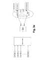
- FIG. 2shows a laser camera having multiple frequency lasers for multispectral imaging applications.
- Multiple lasersLaser Freq 1-Laser Freq N
- Theythen bounce off a biaxial moving mirror (or a separate X and Y mirror) to produce a two-dimensional projection pattern.
- the patterntravels along Path O to a Body Part.
- Some of the Laser Freq wavelengthspenetrate the Body Part and travel to the Internal Structure.
- the various Laser Freq wavelengthseach interact with the internal structure in differing ways (varying levels of absorption and reflections).
- the reflections of the Laser Frequencies 1-Nreturn to Photo Detector A and Photo Detector B along Path A and Path B respectively.
- the Photo Detectorsmay be, for example, a photo diode.
- each Laser Freq 1-Nis sequentially turned on for one frame of projection.
- the reflected light received at Photo Detectors A+B for that frameis then stored in a first frame memory location (not shown).
- a multispectral imageis stored in sequential frames of memory locations 1-N.
- a characteristic of the system shown in FIG. 2is that some portion of the projected Laser Freqs 1-N are reflected off the surface of the Body Part back to the Photo Detectors A+B.
- the reflections off the surface of the Body Partare essentially “noise” to the system.
- External structuressuch a hair, scars, curvature of the body part, differences in reflectivity of exterior regions of the Body Part, all have the effect of generating noise that detract from imaging the Internal Structure.
- Algorithmscan be written to help distinguish between the Internal Structure and the “noise”, however, such algorithms are rarely perfect.
- FIG. 3Ashows a system similar to that of FIG. 2 except that the Photo Detectors A and B are moved and are placed in a way that no light from lasers 1-N reflected from the surface of the skin can reach them. For example, they may be physically touching the skin of the Body Part ( FIG. 3A ).
- This type of systemwill be referred hereinafter as a transillumination laser system, wherein the Laser 1-N, upon hitting the Internal Structure, is then carried internal to the Body Part, with some portion of the light (shown as Path A and Path B) eventually hitting the Photo Detector A and/or B which are placed against the skin of the Body Part.
- the Laser Light that reaches Photo Detector A and/or Bvary as a function of the Internal Structure's absorption and reflection of the Laser Light.
- the presence of a highly absorptive tissue in the light pathwould decrease the signal generated by the Photo Detectors, while the presence of a highly scatterings tissue would increase it.
- the position of the Photo Detectorsdoes not need to be on the side opposite the output laser Path O.
- the Photo Detectorscan be placed anywhere on the Body Part, as long as sufficient internally carried light manages to reach the Photo Detectors.
- the Photo Detectorshave to be physically touching the skin of the Body Part. Instead, they may configured to have their Field-of-View (FOV) restricted to areas of the skin the Body Part which are not directly illuminated by lasers 1-N ( FIG. 3 b ).
- the FOVmay be shaped by lenses, Fresnel lenses, curved mirrors or other optical elements. Additionally, the FOV of the Photo Detectors does not have to be stationary. Instead, it can be moving synchronously with the scanning system in such manner that no light from lasers 1-N reflected from the surface of the skin can reach them.
- the transillumination laser system of FIG. 3 A/ FIG. 3BAs the intensity of the Laser 1-N is increased, none of reflections off the surface of the Body Part are projected onto Photo Detector A or B. Accordingly, the power of Laser 1-N can be significantly increased to allow for imaging of deeper Internal Structures without concern for saturation due to reflections off the surface of the Body Part. Further, surface artifacts such as hair and surface blemishes are largely ignored. Essentially, the transillumination system allows for a greater signal to noise separation between the internal structure (the signal) and the reflections occurring off the surface of the Body Part (the noise). This allows for a much higher contrast ratio image of the underlying Internal Structure. In both FIGS.
- a wide-band laserwhich emits light of different wavelength simultaneously, may be used.
- Such lasersare known to be constructed with active media been confined to an optical fiber with various doping elements with overlapping emission spectra.
- the pulsed lasers with ultra-short pulsesmay be used where the spectrum is broadened by the sidebands of the frequencies associated with the pulse duration.
- One example of such lasersis a mode-locked laser.
- identical Photo Detectors with broadband responsemay have color filters which limit the response of each Detector to a narrow band of wavelengths ( FIG. 9 ).
- the filtersmay be applied selectively, by moving or masking parts of the filter either mechanically ( FIG. 9 b ). or electro-optically ( FIG. 9 c ), using electronically-controlled optical elements such as LCD shutters.
- color-resolved Detectorsmay be used, where the light of different wavelength is directed toward different detector elements by a grating or other suitable optical element ( FIG. 9 d ).
- FIG. 4shows a 5 by 5 array of Photo Detectors.
- This array of Photo Detectorsis then placed in contact with the Body Part to receive the internally reflected Laser 1-N.
- the arraycan be placed anywhere on the Body Part except along optical Path O of FIG. 3 A/ FIG. 3B .
- a large array of Photo Detectorsincreases the photo detection area, thereby capturing more of the internally reflected light.
- the Photo Detector arraycan uniformly distribute the receiving Photo Detectors over area so that it more uniformly receives the internally reflected light. In this manner, “hot spots” associated with fewer Photo Detectors can be minimized.
- FIG. 5shows an embodiment wherein a Photo Detector Ring is placed around the Projected Area of the Laser 1-N. More specifically, it is a view from the perspective of the mirrors of FIG. 3 .
- the ringis placed against the surface of the Body Part in a position such that the Laser 1-N projected along Path O in FIG. 3 A/ FIG. 3B falls inside the inner edge of the Ring.
- the Lasers 1-Npenetrates into the Body Part and interacts with the Inner Structure.
- the Lasers 1-Nscatter inside the Body Part with a portion of the light being returned to the Photo Detector ring wherein it is detected.
- the detected lightcorresponds to the Inner Structure.
- Lasers 1-N scattering off the surface of the Body Partdo not reach the Photo Detectors on the Photo Detector ring, and therefore, do not interfere with the signal created when the Lasers 1-N interact with the Inner Structure. Accordingly, the power of the Lasers 1-N can be increased substantially to reach deeper Inner Structures without having the surface reflections creating “noise”.
- the Photo Detectorsare not shown with the electronics attaching them to a system.
- Such connectivity between the Photo Detectors and the systemcan be via a wired connection, a wireless connection, an optical connection, or any other transmission technique.
- the Photo Detector array of FIG. 4can be built into an armrest of a phlebotomy chair. In this case, when a person's arm is placed down on the armrest, the Photo Detectors are in contact with the skin.
- the photo array of FIG. 4can be a wireless patch which gets affixed with some type of temporary adhesive to the body part and which wireless communicates the output of the Photo Detectors to the system.
- transillumination laser systems described hereincan be utilized as a multispectral system for detecting bruising and erythema (which might indicate developing pressure ulcers).
- article http://www.laserfocusworld.com/display_article/368543/12/none/none/News/MEDICAL-IMAGING:-Real-time-multispectral-imager-promises-portable-diagnosidescribes a conventional CCD camera system for detection have a masked filter array for receiving images with the following frequencies of light 460, 525, 577 and 650 nm for detection of bruising or 540, 577, 650 and 970 for detection of erythema.
- a transillumination laser systemutilizing the frequencies, for example 460, 525, 540, 577, 650 and 970 nm can be configured as described in FIGS. 3 to 6 for the detection of both bruising and erythema.
- the CCD camera system describedis further limited in that the number of pixels of the CCD array gets reduced due to the masked filter. Accordingly, the density of the CCD imaging gets divided down by the number of frequencies in the mask.
- the laser systemdoes not have this limitation in that a complete frame can be taken with each frequency of laser light.
- the transillumination described hereinis applicable to the single frequency detection systems described in the parent applications hereto for the detection of blood vessels within a body.
- FIG. 6Described in FIG. 6 is a closed loop laser imaging system that is capable of capturing images with very high dynamic range.
- laser image capture systemsare described in which the projected laser light is provided by a raster scanned laser beam.
- the laser, scanning mirrors, photo diodes, mirror drivescan all be the same as previously described.
- the laser beam brightnessis controlled by a high speed DAC (digital to analog converter).
- This DACis capable of varying the intensity of the laser at a very high rate (hundreds to thousands of times in each horizontal scan).
- Each segment of a duration corresponding to a desired resolution of the imagewill be referred hereafter as a pixel.
- Each pixel of the imagehas a memory location in the Frame Memory Buffer.
- Each pixelhas a defined location on the object defined by a time slot in the frame.
- a Photo Detectorreceives the reflected light and provides a corresponding voltage to the Amplifier (DC coupled). The output is then provided to the Comparator (One Bit Logic Output) that in turn provides one bit of data. That one bit indicates whether the laser was “too bright” or “too dark” for that pixel. The result is then stored as Pixel brightness information and is updated with every frame. Stored pixel brightness is changed up or down depending on the Photo Detector bit. For maximum light contrast sensitivity, pixel data is always changed by at least one bit every frame. In this manner the closed loop projection image is constantly capturing.
- FIG. 7is a flow chart illustrating the functioning of the system of FIG. 6 .
- the systemrequires multiple frames to fully capture an image. For example, for 8 bits (255 shades), new image capture requires 8 frames. At 60 frames per second, that's 0.13 seconds to capture. After capture, image is maintained and updated with every frame. Since laser brightness (the DAC setting) is adjusted for each pixel, the reflected light for each pixel approaches one value. That value is the midpoint of the analog Photo Detector signal range. This scheme allows the highest contrast sensitivity and highest DC gain in the front end, because the analog signal approaches a flat line. Therefore the dynamic range of the system is not limited by the dynamic range or speed of the Photo Detector amplifier chain.
- the dynamic range of the systemwould be generally equal to the product of the bit resolutions of the laser driver and the ADC, while the number of frames needed to capture a full-resolution image will be equal to a dividend of the bit resolutions of the laser driver and the ADC.
- the time period during the top scan line of the imageis reserved for Laser calibration.
- the laseris driven to a defined maximum and then minimum brightness.
- minimum brightnessthe DC bias on the Photo Detector amplifier is adjusted to compensate for any change in ambient room lighting.
- FIG. 6describes a system with a single laser
- a multiple laser systemutilizing the closed loop projection method.
- Each frequency of lasercan be sequentially cycled for a frame.
- multiple photo detectorscan be filtered; each arranged to receive only one of the specific frequencies of laser light.
- each frequency of lightcan concurrently be processed as shown in FIG. 6 .
- red, green and blue laserscan be utilized, wherein each color has a corresponding Frame Buffer Memory. This would function as a color image capture device.
- a multispectral systemscan be build, utilizing the frequencies described above for detection of bruising and erythema. Further, any frequencies of laser can be utilized provided that the photo detectors are capable of receiving such frequencies.
- the information captured at one wavelengthmay be used to adjust the laser power of different wave-length.
- Such wavelength cross-couplingmay increase accuracy and/or shorten acquisition time of a multispectral closed loop laser imaging system.
- the multispectral laser system FIG. 2 , the Transillumination Laser System FIGS. 3 to 5 and the Closed Loop Projection system FIG. 6can be combined together in a single system so that the advantages of each are provided.
- the objectis a Body Part
- the multispectral laser system FIG. 2the Transillumination Laser System FIGS. 3 to 5 and the Closed Loop Projection system FIG. 6 can be utilized on objects other than Body Parts.
- theycan be used on metals for detecting stress fractures, or can be used on plastic parts for detecting imperfections.
- FIG. 8shows a Laser Camera for capturing images of teeth.
- the Laser Cameracan be designed as previously described in this application and the parent applications.
- a 1310 nm lasercan be utilized as the laser source for imaging. It is known that the frequency of 1310 nm partially passes through teeth. The presence of cavity or other abnormalities will interfere with the reflection of the light.
- the laser lightis transmitted in a raster pattern (or repetitive pattern) towards the teeth. Given that the tooth is relatively small, the laser beam is focused down to a very small spot size by the focusing lens within the Laser Camera. The maximum angle of the of transmitted pattern is made relatively small so that the light falls on a single tooth (or a small number of teeth).
- the Laser Cameracan be configured as a Transillumination Laser Camera, as previously described.
- a Photo Detector Insertcontaining multiple Photo Diodes, can be placed inside the mouth of the patient and pressed against the backside of the teeth.
- the Photo Detector Insertwill receive the laser light that is transmitted through the tooth.
- the Photo Detector Insertcan be molded out of a transmissive gummy material so that it can slightly adhere to the backside of the teeth and provides an optical path for the 1310 nm light that scatters within the tooth and passes the light to the Photo Diodes.
- the light which is received by the Photo Detector Insertis converted to a signal (circuit not shown) which is then communicated (either wired or wirelessly) to the Laser Camera where the results are clocked into an image memory. Once a frame of data is clocked into an image memory it can then be output on a Monitor where the user can view the image of the teeth.
- the Laser Cameracan be designed as a closed loop imaging system as describe previously in FIGS. 6 and 7 . Without the closed loop imaging system, if there are gaps between the teeth, the projected laser will pass through such gaps and saturate the Photo Detector Insert. The very high dynamic range provided by the closed loop imaging system will be beneficial in being able to pick out subtle details, such as cavities and cracks, that are directly next to the very bright spots caused by the gaps in the teeth. The laser power will be able to be substantially increased at specific pixels requiring more illumination, while being reduced requiring a lesser light source (such as the gaps in the teeth).
- the Laser Cameracan also be a multispectral camera as previously described, wherein the 1310 nm frequency is utilized with other frequency lasers for detecting other characteristics of the teeth.
Landscapes
- Health & Medical Sciences (AREA)
- Life Sciences & Earth Sciences (AREA)
- Physics & Mathematics (AREA)
- Surgery (AREA)
- General Health & Medical Sciences (AREA)
- Engineering & Computer Science (AREA)
- Biomedical Technology (AREA)
- Heart & Thoracic Surgery (AREA)
- Medical Informatics (AREA)
- Molecular Biology (AREA)
- Biophysics (AREA)
- Animal Behavior & Ethology (AREA)
- Pathology (AREA)
- Public Health (AREA)
- Veterinary Medicine (AREA)
- Vascular Medicine (AREA)
- Audiology, Speech & Language Pathology (AREA)
- Dentistry (AREA)
- Oral & Maxillofacial Surgery (AREA)
- Spectroscopy & Molecular Physics (AREA)
- Investigating Or Analysing Materials By Optical Means (AREA)
Abstract
Description
- 1. It is an object of the invention to use a laser camera to detect characteristics of an observed object based on the reflection and absorption of the laser light or based on the re-emission of absorbed light at a different wavelength than the incident light.
- 2. It is an object of the invention to use a single or multiple wavelengths of laser light to detect characteristics of an observed object based on the reflection and absorption of the laser light based or the re-emission of absorbed light at a different wavelength than the incident light.
- 3. It is an object of the invention to use multi-spectral imaging by capturing light from wavelengths beyond just the visible light range, such as infrared and UV. This allows extraction of additional information that the human eye fails to capture with its receptors for red, green and blue.
- 4. It is an object of the invention to use hyper-spectral imaging by capturing information from a plurality of wavelengths including and beyond the visible light range, such as infrared and UV. This allows extraction of additional information that the human eye fails to capture with its broadband receptors.
- 5. It is an object of the invention to detect characteristics of the observed object both of the surface of the observed object when it its opaque and of the surface and below the surface when the object is translucent.
- 6. It is an object of the invention to improve the quality of detection of characteristics of the observed object by iteratively varying in real time the intensity of the light emitted by the laser camera based on the previously detected characteristics of the observed object
- 7. It is an object of the invention to present detected characteristics of the observed object back on to the object itself or on to a display visible to the user of the device or both using contrast, color, false color, icons or text or a combination of these modalities.
- 8. It is an object of the invention to capture detected characteristics of the observed object for the purpose of record keeping or for the purpose of post processing or for the purposes of detecting changes and trends in the observed object or a combination of these purposes.
- 9. It is an object of the invention to combine the detected characteristics of the observed object with external sources of data for the purposes of refining and/or extending the meaning of the detected characteristics.
- 10. It is an object of the invention to improve the detection characteristics of the system by using transillumination.
- 11. It is an object of the invention to detect characteristics of many types of objects and materials including veins, arteries, teeth, metals and plastics.
- 1. By using more than one wavelength of light for analysis, additional characteristics about the object being scanned can be determined and then this additional information can be re-projected back on to the surface within the visible spectrum making these characteristics visible to a human either as a color-shifted image or as a false-color image. In this embodiment the device acts like a photo spectrometer that re-projects a visible image back on the object.
- 2. Contrast enhancement products rely on differential absorption and reflection of light (i.e. they detect contrast changes) and then re-project that contrast pattern. An alternative embodiment can also use florescence of the object being scanned by shining light of one wavelength on to the object and detecting light at another wavelength returned from the object and then this information being re-projected back on to the surface within the visible spectrum making these characteristics visible. In this embodiment the device acts like a spectroscope that re-projects a visible image back on the object.
- 3. This invention can further use florescence or color change of a material applied to the object being scanned that based on the characteristics of the object exhibits either a color change (and can therefore use contrast enhancement) or a florescence at one or more wavelengths of incident light.
- 1. Less reflection seen in either wavelength when compared to surrounding tissue? Position contains hemoglobin
- 2. Wavelength one reflection<wavelength two reflection? Position contains oxygenated hemoglobin
- 3. Wavelength one reflection>wavelength two reflection? Position contains deoxygenated hemoglobin
- 1. Project an image back on to the object that is scanned using a visible wavelength laser showing contrast changes between “hit” areas and surrounding areas
- 2. Project said areas using continuously variable brightness to track the contrast changes.
- 3. Project said areas using enhanced contrast to highlight the position of the detected hemoglobin
- 4. Project said areas using a color map (sometimes known as false color) where different colors represent different characteristics.
- 1. Detect for a short period (e.g., a pixel time) and project for a short period.
- 2. Detect for a scan line and project for a scan line.
- 3. Detect for multiple scan lines and project for a scan line.
- 4. Detect for a scan line and repeat project for multiple scan lines.
- 5. Detect for a frame and project for a frame
Claims (26)
Priority Applications (3)
| Application Number | Priority Date | Filing Date | Title |
|---|---|---|---|
| US12/925,166US8594770B2 (en) | 2006-06-29 | 2010-10-14 | Multispectral detection and presentation of an object's characteristics |
| US14/053,775US11051697B2 (en) | 2006-06-29 | 2013-10-15 | Multispectral detection and presentation of an object's characteristics |
| US16/911,487US11523739B2 (en) | 2006-06-29 | 2020-06-25 | Multispectral detection and presentation of an object's characteristics |
Applications Claiming Priority (7)
| Application Number | Priority Date | Filing Date | Title |
|---|---|---|---|
| US11/478,322US8478386B2 (en) | 2006-01-10 | 2006-06-29 | Practitioner-mounted micro vein enhancer |
| US11/700,729US8838210B2 (en) | 2006-06-29 | 2007-01-31 | Scanned laser vein contrast enhancer using a single laser |
| US11/807,359US8489178B2 (en) | 2006-06-29 | 2007-05-25 | Enhanced laser vein contrast enhancer with projection of analyzed vein data |
| US11/823,862US7983738B2 (en) | 2006-01-10 | 2007-06-28 | Three dimensional imaging of veins |
| US12/215,713US8730321B2 (en) | 2007-06-28 | 2008-06-27 | Automatic alignment of a contrast enhancement system |
| US27894809P | 2009-10-14 | 2009-10-14 | |
| US12/925,166US8594770B2 (en) | 2006-06-29 | 2010-10-14 | Multispectral detection and presentation of an object's characteristics |
Related Parent Applications (1)
| Application Number | Title | Priority Date | Filing Date |
|---|---|---|---|
| US11/478,322Continuation-In-PartUS8478386B2 (en) | 2006-01-01 | 2006-06-29 | Practitioner-mounted micro vein enhancer |
Related Child Applications (1)
| Application Number | Title | Priority Date | Filing Date |
|---|---|---|---|
| US14/053,775ContinuationUS11051697B2 (en) | 2006-06-29 | 2013-10-15 | Multispectral detection and presentation of an object's characteristics |
Publications (2)
| Publication Number | Publication Date |
|---|---|
| US20110112407A1 US20110112407A1 (en) | 2011-05-12 |
| US8594770B2true US8594770B2 (en) | 2013-11-26 |
Family
ID=43974701
Family Applications (3)
| Application Number | Title | Priority Date | Filing Date |
|---|---|---|---|
| US12/925,166Active2027-06-23US8594770B2 (en) | 2006-06-29 | 2010-10-14 | Multispectral detection and presentation of an object's characteristics |
| US14/053,775Active2026-08-25US11051697B2 (en) | 2006-06-29 | 2013-10-15 | Multispectral detection and presentation of an object's characteristics |
| US16/911,487Active2027-05-15US11523739B2 (en) | 2006-06-29 | 2020-06-25 | Multispectral detection and presentation of an object's characteristics |
Family Applications After (2)
| Application Number | Title | Priority Date | Filing Date |
|---|---|---|---|
| US14/053,775Active2026-08-25US11051697B2 (en) | 2006-06-29 | 2013-10-15 | Multispectral detection and presentation of an object's characteristics |
| US16/911,487Active2027-05-15US11523739B2 (en) | 2006-06-29 | 2020-06-25 | Multispectral detection and presentation of an object's characteristics |
Country Status (1)
| Country | Link |
|---|---|
| US (3) | US8594770B2 (en) |
Cited By (5)
| Publication number | Priority date | Publication date | Assignee | Title |
|---|---|---|---|---|
| US20140133729A1 (en)* | 2011-07-15 | 2014-05-15 | Koninklijke Philips N.V. | Image processing for spectral ct |
| WO2015120026A1 (en) | 2014-02-04 | 2015-08-13 | Medical Components, Inc. | Light based location and identification of implanted medical devices |
| US11037283B2 (en) | 2018-12-11 | 2021-06-15 | Samsung Electronics Co., Ltd. | Inspecting apparatus based on hyperspectral imaging |
| US11207024B2 (en)* | 2017-07-12 | 2021-12-28 | Boe Technology Group Co., Ltd. | Vascular imaging apparatus and vascular imaging method |
| US12303324B2 (en) | 2018-05-31 | 2025-05-20 | Faction Imaging Inc. | Method of medical imaging using multiple arrays |
Families Citing this family (6)
| Publication number | Priority date | Publication date | Assignee | Title |
|---|---|---|---|---|
| US9072426B2 (en)* | 2012-08-02 | 2015-07-07 | AccuVein, Inc | Device for detecting and illuminating vasculature using an FPGA |
| US10517483B2 (en)* | 2012-12-05 | 2019-12-31 | Accuvein, Inc. | System for detecting fluorescence and projecting a representative image |
| US9430846B2 (en) | 2013-04-19 | 2016-08-30 | Ge Aviation Systems Llc | Method of tracking objects using hyperspectral imagery |
| JP6127207B2 (en) | 2013-05-13 | 2017-05-10 | 執鼎医療科技(杭州)有限公司 | Blood vessel image positioning system |
| WO2014210226A1 (en)* | 2013-06-25 | 2014-12-31 | Public Service Solutions, Inc. | Side-scan infrared imaging devices |
| US20150119802A1 (en)* | 2013-10-28 | 2015-04-30 | Constantin Dumitrescu | Portable vein locating device |
Citations (100)
| Publication number | Priority date | Publication date | Assignee | Title |
|---|---|---|---|---|
| US3818129A (en) | 1971-06-30 | 1974-06-18 | Hitachi Ltd | Laser imaging device |
| FR2289149A1 (en) | 1974-11-04 | 1976-05-28 | Siemens Ag | DEVICE FOR PRECISELY AND RAPID LOCATION OF VESSELS CROSSED BY LIQUIDS IN THE HUMAN BODY AND FOR PRECISELY INTRODUCING A PUNCTURE CANNULA IN THESE VESSELS |
| US4182322A (en) | 1978-08-04 | 1980-01-08 | Miller Larry C | Head harness device |
| US4265227A (en) | 1979-10-03 | 1981-05-05 | The Hospital And Welfare Board Of Hillsborough County | Infant extremity positioner and illuminator |
| US4312357A (en) | 1976-12-03 | 1982-01-26 | Sinus Medical Equipment Ab | Transillumination diagnostic method and apparatus |
| US4321930A (en) | 1977-06-28 | 1982-03-30 | Duke University, Inc. | Apparatus for monitoring metabolism in body organs |
| US4495949A (en) | 1982-07-19 | 1985-01-29 | Spectrascan, Inc. | Transillumination method |
| US4502075A (en) | 1981-12-04 | 1985-02-26 | International Remote Imaging Systems | Method and apparatus for producing optical displays |
| US4619249A (en) | 1985-07-24 | 1986-10-28 | Kim Landry | Transcutaneous intravenous illuminator |
| US4669467A (en)* | 1985-03-22 | 1987-06-02 | Massachusetts Institute Of Technology | Mode mixer for a laser catheter |
| US4817622A (en) | 1986-07-22 | 1989-04-04 | Carl Pennypacker | Infrared imager for viewing subcutaneous location of vascular structures and method of use |
| US5214458A (en) | 1992-01-14 | 1993-05-25 | Matsubara Kenki Kogyo Kabushiki Kaisha | Display apparatus |
| US5261581A (en) | 1992-04-10 | 1993-11-16 | Harden Sr Ralph E | Holster for bow string release or tool |
| US5406070A (en) | 1993-12-16 | 1995-04-11 | International Business Machines Corporation | Method and apparatus for scanning an object and correcting image data using concurrently generated illumination data |
| US5423091A (en) | 1994-09-22 | 1995-06-13 | The Tram Corporation | Headband following a wearer's hairline |
| JPH0823501A (en) | 1994-07-11 | 1996-01-23 | Fujitsu General Ltd | Projection type image display device |
| US5519208A (en) | 1994-09-29 | 1996-05-21 | Esparza; Joel | Infrared aided method and apparatus for venous examination |
| US5541820A (en) | 1995-01-26 | 1996-07-30 | Mclaughlin; Michael K. | Combined lamp and movie projector |
| US5542421A (en)* | 1992-07-31 | 1996-08-06 | Frederick Erdman Association | Method and apparatus for cardiovascular diagnosis |
| US5603328A (en) | 1993-01-18 | 1997-02-18 | The State Of Israel, Ministry Of Defence, Armament Development Authority | Infra-red vascular angiography system |
| US5608210A (en) | 1994-09-29 | 1997-03-04 | Esparza; Joel | Infrared aided method and apparatus for venous examination |
| US5631976A (en) | 1994-04-29 | 1997-05-20 | International Business Machines Corporation | Object imaging system |
| US5678555A (en) | 1996-04-08 | 1997-10-21 | O'connell; Peter | Method of locating and marking veins |
| US5772593A (en) | 1995-07-12 | 1998-06-30 | Fuji Photo Film Co., Ltd. | Surgical operation aiding system |
| US5836877A (en) | 1997-02-24 | 1998-11-17 | Lucid Inc | System for facilitating pathological examination of a lesion in tissue |
| US5860967A (en) | 1993-07-21 | 1999-01-19 | Lucid, Inc. | Dermatological laser treatment system with electronic visualization of the area being treated |
| US5969754A (en)* | 1996-12-09 | 1999-10-19 | Zeman; Herbert D. | Contrast enhancing illuminator |
| US5982553A (en) | 1997-03-20 | 1999-11-09 | Silicon Light Machines | Display device incorporating one-dimensional grating light-valve array |
| US5988817A (en) | 1997-02-28 | 1999-11-23 | Rds Corporation | Multiprojection system |
| US5995856A (en) | 1995-11-22 | 1999-11-30 | Nellcor, Incorporated | Non-contact optical monitoring of physiological parameters |
| US6032070A (en) | 1995-06-07 | 2000-02-29 | University Of Arkansas | Method and apparatus for detecting electro-magnetic reflection from biological tissue |
| US6056692A (en) | 1998-07-08 | 2000-05-02 | Schwartz; John Q. | Apparatus and method for locating and marking blood vessels |
| US6061583A (en) | 1995-12-27 | 2000-05-09 | Sysmex Corporation And Ken Ishihara | Noninvasive blood analyzer |
| US6135599A (en) | 1999-03-26 | 2000-10-24 | Fang; Chen-Tai | Projection ornament |
| US6149644A (en) | 1998-02-17 | 2000-11-21 | Altralight, Inc. | Method and apparatus for epidermal treatment with computer controlled moving focused infrared light |
| US6178340B1 (en) | 1998-08-24 | 2001-01-23 | Eduardo Svetliza | Three-dimensional infrared imager for subcutaneous puncture and study of vascular network |
| US6230046B1 (en) | 1995-05-16 | 2001-05-08 | The United States Of America As Represented By The Secretary Of The Air Force | System and method for enhanced visualization of subcutaneous structures |
| US6251073B1 (en) | 1999-08-20 | 2001-06-26 | Novasonics, Inc. | Miniaturized ultrasound apparatus and method |
| US6263227B1 (en) | 1996-05-22 | 2001-07-17 | Moor Instruments Limited | Apparatus for imaging microvascular blood flow |
| US20010056237A1 (en)* | 1996-11-19 | 2001-12-27 | Cane Michael Roger | Method of and apparatus for investigating tissue histology |
| US6334850B1 (en) | 1997-11-19 | 2002-01-01 | Seiko Epson Corporation | Method of detecting pulse wave, method of detecting artery position, and pulse wave detecting apparatus |
| US20020016533A1 (en) | 2000-05-03 | 2002-02-07 | Marchitto Kevin S. | Optical imaging of subsurface anatomical structures and biomolecules |
| US6424858B1 (en) | 1998-11-12 | 2002-07-23 | John L. Williams | Apparatus and method for viewing vasculature of a human being |
| US20020118338A1 (en) | 2001-02-19 | 2002-08-29 | Yoshimi Kohayakawa | Ophthalmologic apparatus |
| US6463309B1 (en) | 2000-05-11 | 2002-10-08 | Hanna Ilia | Apparatus and method for locating vessels in a living body |
| US6464646B1 (en) | 1998-03-23 | 2002-10-15 | Veino-Med Ltd. | Instrument and method for locating and marking a hot spot in a person's body tissue |
| JP2002328428A (en) | 2001-05-01 | 2002-11-15 | Sony Corp | Projector and image projection system |
| US20030018271A1 (en) | 2001-07-02 | 2003-01-23 | Kimble Allan Wayne | Simplified and lightweight system for enhanced visualization of subcutaneous hemoglobin-containing structures |
| US6542246B1 (en) | 1998-11-20 | 2003-04-01 | Fuji Photo Film Co., Ltd. | Blood vessel imaging system |
| US6556858B1 (en) | 2000-01-19 | 2003-04-29 | Herbert D. Zeman | Diffuse infrared light imaging system |
| US6556854B1 (en) | 1998-11-20 | 2003-04-29 | Fuji Photo Film Co., Ltd. | Blood vessel imaging system using homodyne and heterodyne effects |
| US6648227B2 (en) | 2000-10-20 | 2003-11-18 | Symbol Technologies, Inc. | Scanning module for a bar code reader with a focusing lens |
| US20040022421A1 (en) | 2002-07-31 | 2004-02-05 | Fujitsu Limited | Processor with personal verification function and operating device |
| US6690964B2 (en) | 2000-07-12 | 2004-02-10 | Siemens Aktiengesellschaft | Method and device for visualization of positions and orientation of intracorporeally guided instruments during a surgical intervention |
| US6689075B2 (en) | 2000-08-25 | 2004-02-10 | Healthsouth Corporation | Powered gait orthosis and method of utilizing same |
| US6702749B2 (en) | 2001-07-24 | 2004-03-09 | Siemens Corporate Research, Inc. | Optical needle guide for ultrasound guided needle biopsy |
| US6782161B2 (en) | 2001-02-05 | 2004-08-24 | Derma Laser Inc. | Laser diode apparatus provided with an aiming beam and injection method therefor |
| JP2004237051A (en) | 2003-02-06 | 2004-08-26 | Ogawa Hiroteru | Blood vessel visualizing method and apparatus |
| US20040171923A1 (en) | 2002-12-06 | 2004-09-02 | Kalafut John F. | Devices, systems and methods for improving vessel access |
| US20050017924A1 (en) | 2002-12-20 | 2005-01-27 | Utt Steven W. | Display system having a three-dimensional convex display surface |
| US20050043596A1 (en) | 1996-07-12 | 2005-02-24 | Non-Invasive Technology, Inc., A Delaware Corporation | Optical examination device, system and method |
| US20050047134A1 (en) | 1997-08-26 | 2005-03-03 | Color Kinetics | Controlled lighting methods and apparatus |
| US6882875B1 (en) | 1997-09-29 | 2005-04-19 | Boston Scientific Corporation | Visible display for an interventional device |
| US20050113650A1 (en) | 2000-06-16 | 2005-05-26 | Christopher Pacione | System for monitoring and managing body weight and other physiological conditions including iterative and personalized planning, intervention and reporting capability |
| US20050135102A1 (en) | 2001-06-26 | 2005-06-23 | Allan Gardiner | Illuminator with peak wavelength variation |
| US20050141069A1 (en) | 2003-12-31 | 2005-06-30 | Wood Frederick F. | Method and apparatus for conserving power in a laser projection display |
| US6913202B2 (en) | 1999-06-07 | 2005-07-05 | Metrologic Instruments, Inc. | Planar laser illumination and imaging (PLIIM) engine |
| US20050157939A1 (en) | 2004-01-16 | 2005-07-21 | Mark Arsenault | Processes, products and systems for enhancing images of blood vessels |
| US20050161051A1 (en) | 2003-01-08 | 2005-07-28 | Cyberheart, Inc. | System for non-invasive heart treatment |
| US6923762B1 (en) | 2001-11-01 | 2005-08-02 | Frank C. Creaghan, Jr. | Venoscope apparatus |
| US20050174777A1 (en) | 2004-02-10 | 2005-08-11 | Rita Cooper | Sensor-activated audible story lamp |
| US20050175048A1 (en) | 2003-12-31 | 2005-08-11 | Symbol Technologies, Inc. | Method and apparatus for controllably reducing power delivered by a laser projection display |
| US20050215875A1 (en) | 2004-03-19 | 2005-09-29 | Sroy Khou | Method and device for locating position of veins on body |
| US20050281445A1 (en) | 2004-01-16 | 2005-12-22 | Ronald Marcotte | System and method for locating and accessing a blood vessel |
| US6980852B2 (en) | 2002-01-25 | 2005-12-27 | Subqiview Inc. | Film barrier dressing for intravascular tissue monitoring system |
| US20060025679A1 (en) | 2004-06-04 | 2006-02-02 | Viswanathan Raju R | User interface for remote control of medical devices |
| US20060058683A1 (en)* | 1999-08-26 | 2006-03-16 | Britton Chance | Optical examination of biological tissue using non-contact irradiation and detection |
| US20060081252A1 (en) | 2004-10-19 | 2006-04-20 | Wood Thomas J | Headgear |
| US20060103811A1 (en) | 2004-11-12 | 2006-05-18 | Hewlett-Packard Development Company, L.P. | Image projection system and method |
| US20060122515A1 (en) | 2000-01-19 | 2006-06-08 | Luminetx Corporation | Projection of subsurface structure onto an object's surface |
| US20060129038A1 (en) | 2004-12-14 | 2006-06-15 | Zelenchuk Alex R | Optical determination of in vivo properties |
| US20060129037A1 (en) | 2004-12-14 | 2006-06-15 | Kaufman Howard B | Optical determination of in vivo properties |
| US20060173351A1 (en) | 2005-01-03 | 2006-08-03 | Ronald Marcotte | System and method for inserting a needle into a blood vessel |
| US20060232660A1 (en) | 2002-07-02 | 2006-10-19 | Tomohiro Nakajima | Optical scanner and image forming apparatus |
| US20060253010A1 (en) | 2004-09-28 | 2006-11-09 | Donald Brady | Monitoring device, method and system |
| US20060271028A1 (en) | 2005-02-18 | 2006-11-30 | Palomar Medical Technologies, Inc. | Dermatological treatment device |
| US7158660B2 (en) | 2002-05-08 | 2007-01-02 | Gee Jr James W | Method and apparatus for detecting structures of interest |
| US20070016079A1 (en) | 2005-04-04 | 2007-01-18 | Freeman Jenny E | Hyperspectral imaging in diabetes and peripheral vascular disease |
| US20070115435A1 (en) | 2003-12-15 | 2007-05-24 | Koninklojke Philips Electronics N.V. | Projector and method of projecting an image having multiple image sizes |
| US7239909B2 (en) | 2000-01-19 | 2007-07-03 | Luminetx Technologies Corp. | Imaging system using diffuse infrared light |
| US7247832B2 (en) | 2005-09-09 | 2007-07-24 | Silicon Light Machines Corporation | Signal processing circuit and method using analog voltage signal to pulse width modulation conversion |
| US7283181B2 (en) | 2002-01-31 | 2007-10-16 | Hewlett-Packard Development Company, L.P. | Selectable color adjustment for image display |
| US7333213B2 (en) | 1998-05-28 | 2008-02-19 | The General Hospital Corporation | Confocal microscopy |
| US20080045841A1 (en) | 2006-06-29 | 2008-02-21 | Fred Wood | Scanned laser vein contrast enhancer |
| US20080147147A1 (en) | 2006-12-18 | 2008-06-19 | Medrad, Inc. | Vein locating device for vascular access procedures |
| US20080194930A1 (en) | 2007-02-09 | 2008-08-14 | Harris Melvyn L | Infrared-visible needle |
| US7608057B2 (en) | 1997-08-20 | 2009-10-27 | B. Braun Meisungen Ag | Protective device for an injection needle |
| US20100051808A1 (en) | 2007-10-19 | 2010-03-04 | Luminetx Corporation | Imaging System Using Infrared Light |
| US20100177184A1 (en) | 2007-02-14 | 2010-07-15 | Chrustie Medical Holdings, Inc. | System And Method For Projection of Subsurface Structure Onto An Object's Surface |
| US20100312120A1 (en) | 2008-07-18 | 2010-12-09 | Meier Joseph H | Handheld imaging devices and related methods |
Family Cites Families (197)
| Publication number | Priority date | Publication date | Assignee | Title |
|---|---|---|---|---|
| US2289149A (en)* | 1940-07-26 | 1942-07-07 | Westinghouse Electric & Mfg Co | Electrical relay |
| US3136310A (en) | 1960-01-18 | 1964-06-09 | Bausch & Lomb | Optical catheter |
| US3349762A (en) | 1964-10-21 | 1967-10-31 | Optics Technology Inc | Blood flow indicator and process |
| US3511227A (en) | 1967-02-27 | 1970-05-12 | Univ Utah | Measurement of blood flow using coherent radiation and doppler effect |
| US3527932A (en) | 1967-11-16 | 1970-09-08 | James J Thomas | Transilluminating flashlight |
| DE1927868C3 (en) | 1969-05-31 | 1975-06-05 | Siemens Ag, 1000 Berlin Und 8000 Muenchen | Device for the precise and rapid location of blood vessels or the like and for the accurate insertion of an injection cannula into these vessels |
| CH565423A5 (en) | 1974-03-07 | 1975-08-15 | Dreiding Andre | |
| US3984629A (en) | 1974-12-23 | 1976-10-05 | Rca Corporation | Flying spot scanner unaffected by ambient light |
| US4185808A (en) | 1975-02-10 | 1980-01-29 | Cbs Inc. | Connector hardware for percussive instruments |
| US4057784A (en) | 1976-09-27 | 1977-11-08 | Sperry Rand Corporation | Bi-directional scanner assembly |
| US4109647A (en) | 1977-03-16 | 1978-08-29 | The United States Of America As Represented By The Secretary Of The Department Of Health, Education And Welfare | Method of and apparatus for measurement of blood flow using coherent light |
| US4213678A (en) | 1977-09-29 | 1980-07-22 | Retina Foundation | Scanning ophthalmoscope for examining the fundus of the eye |
| US4162405A (en) | 1978-05-23 | 1979-07-24 | Britton Chance | Flying spot fluoro-meter for oxidized flavoprotein and reduced pyridine nucleotide |
| US4315318A (en) | 1978-12-26 | 1982-02-09 | Fuji Photo Film Co., Ltd. | Method and apparatus for processing a radiation image |
| US4393366A (en) | 1981-02-17 | 1983-07-12 | Eye-D Development Ii Ltd. | Rotating beam ocular identification apparatus and method |
| US4703758A (en) | 1982-09-30 | 1987-11-03 | Yoshiaki Omura | Non-invasive monitoring of blood flow and cerebral blood pressure using ultra miniature reflection type photoelectric plethysmographic sensors or ultrasonic doppler flow meter |
| JPS5994037A (en) | 1982-11-19 | 1984-05-30 | Shimadzu Corp | Apparatus for counting corpuscle |
| US4536790A (en) | 1982-11-26 | 1985-08-20 | Thomson-Csf Broadcast, Inc. | Apparatus and method for fluoroscopic imaging of a body |
| US4565968A (en) | 1983-02-16 | 1986-01-21 | Albert Macovski | Blood vessel projection imaging system using nuclear magnetic resonance |
| US4576175A (en) | 1983-09-06 | 1986-03-18 | Moshe Epstein | Biopsy attachment for ultrasonic probe |
| JPS60108043A (en) | 1983-11-18 | 1985-06-13 | キヤノン株式会社 | Blood vessel position indicating device |
| US4567896A (en) | 1984-01-20 | 1986-02-04 | Elscint, Inc. | Method and apparatus for calibrating a biopsy attachment for ultrasonic imaging apparatus |
| SE8400289D0 (en) | 1984-01-20 | 1984-01-20 | Perimed Kb | SET AND DEVICE FOR DETERMINATION OF THE BLOOD FLOOD IN THE EXTRA BLOCK CARTRIDGE OF A TISSUE |
| WO1985004088A1 (en) | 1984-03-20 | 1985-09-26 | Joseph Rice | Method and apparatus for the identification of individuals |
| IT1206462B (en) | 1984-08-07 | 1989-04-27 | Anic Spa | MULTI-WAVE LENGTH PULSED LIGHT PHOTOMETER FOR NON-INVASIVE MONITORING. |
| US4596254A (en) | 1984-12-18 | 1986-06-24 | Tsi Research Associates Limited Partnership | Laser Doppler flow monitor |
| US4697147A (en) | 1985-11-14 | 1987-09-29 | Metriflow, Inc. | Blood flow imaging using a CW NMR technique |
| DE3709709A1 (en) | 1986-03-25 | 1987-10-08 | Asahi Optical Co Ltd | AUXILIARY LIGHT PROJECTING DEVICE FOR A REMOVAL LOCKING SYSTEM |
| US4766299A (en) | 1986-03-28 | 1988-08-23 | Spectra-Physics, Inc. | Hand-mounted bar code reader |
| JPS6323645A (en) | 1986-05-27 | 1988-01-30 | 住友電気工業株式会社 | Reflection heating type oxymeter |
| US4901019A (en) | 1986-08-18 | 1990-02-13 | The General Hospital Corporation | Three-dimensional imaging |
| US4799103A (en) | 1986-10-10 | 1989-01-17 | Seton Health Care Foundation | Three-dimensional laser driven display apparatus |
| US5146923A (en) | 1986-12-18 | 1992-09-15 | Dhawan Atam P | Apparatus and method for skin lesion examination |
| AU608807B2 (en) | 1987-03-03 | 1991-04-18 | Hitoshi Fujii | Apparatus for monitoring bloodstream |
| US4861973A (en) | 1987-06-18 | 1989-08-29 | Spectra-Physics, Inc. | Optical scan pattern generating arrangement for a laser scanner |
| FR2617602B1 (en) | 1987-07-03 | 1989-10-20 | Thomson Csf | METHOD AND SYSTEM FOR PHOTON FREQUENCY MARKING TRANSILLUMINATION IMAGING |
| US4780919A (en) | 1987-10-20 | 1988-11-01 | Harrison Mildred B | Hospital bed |
| JPH0827235B2 (en)* | 1987-11-17 | 1996-03-21 | 倉敷紡績株式会社 | Spectroscopic method for measuring sugar concentration |
| US4846183A (en) | 1987-12-02 | 1989-07-11 | The Boc Group, Inc. | Blood parameter monitoring apparatus and methods |
| US4938205A (en) | 1988-05-27 | 1990-07-03 | The University Of Connecticut | Endoscope with traced raster and elemental photodetectors |
| US4899756A (en) | 1988-07-18 | 1990-02-13 | Sonek Jiri D | Articulated needle guide for ultrasound imaging and method of using same |
| US5090415A (en)* | 1989-02-14 | 1992-02-25 | Hamamatsu Photonics Kabushiki Kaisha | Examination apparatus |
| DE3916595A1 (en) | 1989-05-22 | 1990-11-29 | Boehringer Mannheim Gmbh | METHOD FOR NON-RADIOACTIVE MEASURING OF NUCLEIC ACID SYNTHESIS IN EUKARYONTIC CELLS |
| US5504316A (en) | 1990-05-08 | 1996-04-02 | Symbol Technologies, Inc. | Laser scanning system and scanning method for reading 1-D and 2-D barcode symbols |
| DE69025950T2 (en) | 1989-10-31 | 1996-09-05 | Gert Nilsson | ARRANGEMENT AND METHOD FOR MEASURING AND PRESENTING LIQUID FLOWS, IN PARTICULAR THE FLOW OF FLOW THROUGH A BODY ORGAN |
| US5074642A (en) | 1989-11-14 | 1991-12-24 | Hicks John W | Multifiber endoscope with fibers having different indices of refraction |
| US5103497A (en) | 1989-11-14 | 1992-04-07 | Hicks John W | Flying spot endoscope |
| US5716796A (en) | 1990-01-23 | 1998-02-10 | Medical Devices Corporation | Optical blood hemostatic analysis apparatus and method |
| US5184188A (en) | 1990-01-23 | 1993-02-02 | Medical Devices Corporation | Optical blood hemostatic analysis apparatus and method |
| US5222495A (en) | 1990-02-02 | 1993-06-29 | Angiomedics Ii, Inc. | Non-invasive blood analysis by near infrared absorption measurements using two closely spaced wavelengths |
| US5966230A (en) | 1990-05-29 | 1999-10-12 | Symbol Technologies, Inc. | Integrated scanner on a common substrate |
| JPH0442944A (en) | 1990-06-06 | 1992-02-13 | Matsushita Electron Corp | Semiconductor device |
| US6671540B1 (en)* | 1990-08-10 | 2003-12-30 | Daryl W. Hochman | Methods and systems for detecting abnormal tissue using spectroscopic techniques |
| US7077327B1 (en) | 1990-09-17 | 2006-07-18 | Metrologic Instruments, Inc. | System for reading bar code symbols using bar code readers having RF signal transmission links with base stations |
| US5371347A (en) | 1991-10-15 | 1994-12-06 | Gap Technologies, Incorporated | Electro-optical scanning system with gyrating scan head |
| WO1992013265A1 (en) | 1991-01-24 | 1992-08-06 | The University Of Maryland | Method and apparatus for multi-dimensional phase fluorescence lifetime imaging |
| US6006126A (en) | 1991-01-28 | 1999-12-21 | Cosman; Eric R. | System and method for stereotactic registration of image scan data |
| DE69227545T2 (en) | 1991-07-12 | 1999-04-29 | Robinson, Mark R., Albuquerque, N.Mex. | Oximeter for the reliable clinical determination of blood oxygen saturation in a fetus |
| US5436655A (en) | 1991-08-09 | 1995-07-25 | Olympus Optical Co., Ltd. | Endoscope apparatus for three dimensional measurement for scanning spot light to execute three dimensional measurement |
| US5418546A (en) | 1991-08-20 | 1995-05-23 | Mitsubishi Denki Kabushiki Kaisha | Visual display system and exposure control apparatus |
| DE4128744C1 (en) | 1991-08-29 | 1993-04-22 | Siemens Ag, 8000 Muenchen, De | |
| US5610387A (en) | 1992-05-15 | 1997-03-11 | Symbol Technologies, Inc. | Portable optical scanning system worn by a user for reading indicia of differing light reflectivity |
| JPH05228098A (en) | 1992-02-20 | 1993-09-07 | Asahi Optical Co Ltd | Thermoendoscope |
| US5756981A (en) | 1992-02-27 | 1998-05-26 | Symbol Technologies, Inc. | Optical scanner for reading and decoding one- and-two-dimensional symbologies at variable depths of field including memory efficient high speed image processing means and high accuracy image analysis means |
| DE69431518D1 (en) | 1993-03-31 | 2002-11-14 | Luma Corp | INFORMATION MANAGEMENT IN AN ENDOSCOPY SYSTEM |
| GB9306897D0 (en) | 1993-04-01 | 1993-05-26 | British Tech Group | Biometric identification of individuals |
| US5946220A (en) | 1993-08-25 | 1999-08-31 | Lemelson; Jerome H. | Computer operated material processing systems and method |
| US5598842A (en) | 1993-09-03 | 1997-02-04 | Toa Medical Electronics Co., Ltd. | Non-invasive blood analyzer and method using the same |
| US5747789A (en) | 1993-12-01 | 1998-05-05 | Dynamics Imaging, Inc. | Method for investigation of distribution of physiological components in human body tissues and apparatus for its realization |
| US5497769A (en) | 1993-12-16 | 1996-03-12 | I.S.S. (Usa) Inc. | Photosensor with multiple light sources |
| US5487740A (en) | 1994-03-02 | 1996-01-30 | Energy Life Systems Corporation | Laser device for ablation of human tissue |
| JPH07255847A (en) | 1994-03-25 | 1995-10-09 | Otax Kk | Blood vessel sensor |
| JP3263275B2 (en) | 1994-04-05 | 2002-03-04 | ザ リージェンツ オブ ザ ユニバーシティ オブ カリフォルニア | Apparatus for laser treatment of living tissue and laser treatment apparatus for flame-like nevus |
| USD362910S (en) | 1994-04-21 | 1995-10-03 | Creaghan Jr Frank C | Instrument for viewing subcutaneous venous structures |
| US5625458A (en) | 1994-11-10 | 1997-04-29 | Research Foundation Of City College Of New York | Method and system for imaging objects in turbid media using diffusive fermat photons |
| JPH08164123A (en) | 1994-12-15 | 1996-06-25 | Nikon Corp | Blood sampling device |
| US5735276A (en) | 1995-03-21 | 1998-04-07 | Lemelson; Jerome | Method and apparatus for scanning and evaluating matter |
| US5655530A (en) | 1995-08-09 | 1997-08-12 | Rio Grande Medical Technologies, Inc. | Method for non-invasive blood analyte measurement with improved optical interface |
| US6240309B1 (en) | 1995-10-06 | 2001-05-29 | Hitachi, Ltd. | Optical measurement instrument for living body |
| US5929443A (en) | 1995-12-18 | 1999-07-27 | The Research Foundation City College Of New York | Imaging of objects based upon the polarization or depolarization of light |
| US5719399A (en) | 1995-12-18 | 1998-02-17 | The Research Foundation Of City College Of New York | Imaging and characterization of tissue based upon the preservation of polarized light transmitted therethrough |
| JPH1020198A (en) | 1996-07-02 | 1998-01-23 | Olympus Optical Co Ltd | Near infrared microscope and microscope observation system using the same |
| US20010006426A1 (en) | 1996-07-18 | 2001-07-05 | Korea Institute Of Science And Technology | Holographic projection screen for displaying a three-dimensional color images and optical display system using the holographic screen |
| US5758650A (en) | 1996-09-30 | 1998-06-02 | Siemens Medical Systems, Inc. | Universal needle guide for ultrasonic transducers |
| US6122042A (en) | 1997-02-07 | 2000-09-19 | Wunderman; Irwin | Devices and methods for optically identifying characteristics of material objects |
| KR100259475B1 (en) | 1997-04-14 | 2000-06-15 | 최환수 | Method for the identification of individuals using the pattern of blood vessels |
| US6523955B1 (en) | 1997-07-07 | 2003-02-25 | Heinrich A. Eberl | Method for improving optic perceptive faculty by modifying the retinal image |
| US6142650A (en) | 1997-07-10 | 2000-11-07 | Brown; David C. | Laser flashlight |
| FR2766943B1 (en) | 1997-07-30 | 1999-10-15 | United Barcode Ind Scanner Tec | OPTOELECTRONIC DEVICE FOR MULTIDIRECTIONAL ACQUISITION OF PLANE OBJECT IMAGES, ESPECIALLY BAR CODES |
| US5947906A (en) | 1997-11-14 | 1999-09-07 | Dawson, Jr.; Fredric O. | Apparatus for enhanced visual venous examination |
| US6436655B1 (en) | 1998-02-09 | 2002-08-20 | Medical Devices Corporation | Rapid quantitative measurement of soluble fibrin in opaque body fluids |
| FR2775589B1 (en) | 1998-03-06 | 2000-04-28 | Cryonic Medical | SELF-CONTAINED, PORTABLE CRYOGENIC APPARATUS USING CARBONIC ANHYDRIDE IN LIQUID / SOLID PHASE |
| US6353753B1 (en) | 1998-05-05 | 2002-03-05 | Stephen Thomas Flock | Optical imaging of deep anatomic structures |
| US6083486A (en) | 1998-05-14 | 2000-07-04 | The General Hospital Corporation | Intramolecularly-quenched near infrared fluorescent probes |
| US6179260B1 (en) | 1998-06-10 | 2001-01-30 | N. Sean Ohanian | Device for coupling an IV stand to a patient transport |
| US6101036A (en) | 1998-06-23 | 2000-08-08 | Silicon Light Machines | Embossed diffraction grating alone and in combination with changeable image display |
| US6113536A (en) | 1998-09-30 | 2000-09-05 | A-Med Systems, Inc. | Device and method of attaching a blood pump and tubes to a surgical retractor |
| US6132379A (en) | 1998-11-04 | 2000-10-17 | Patacsil; Estelito G. | Method and apparatus for ultrasound guided intravenous cannulation |
| US6438396B1 (en) | 1998-11-05 | 2002-08-20 | Cytometrics, Inc. | Method and apparatus for providing high contrast imaging |
| US6272376B1 (en) | 1999-01-22 | 2001-08-07 | Cedars-Sinai Medical Center | Time-resolved, laser-induced fluorescence for the characterization of organic material |
| US6305804B1 (en) | 1999-03-25 | 2001-10-23 | Fovioptics, Inc. | Non-invasive measurement of blood component using retinal imaging |
| US7107116B2 (en)* | 1999-03-29 | 2006-09-12 | Genex Technologies, Inc. | Diffuse optical tomography system and method of use |
| JP2000316866A (en) | 1999-05-06 | 2000-11-21 | Yoshiko Sashide | Recognizing method and recognizing device for blood vessel |
| US6314311B1 (en) | 1999-07-28 | 2001-11-06 | Picker International, Inc. | Movable mirror laser registration system |
| US8494616B2 (en) | 2000-01-19 | 2013-07-23 | Christie Medical Holdings, Inc. | Method and apparatus for projection of subsurface structure onto an object's surface |
| GB0004351D0 (en) | 2000-02-25 | 2000-04-12 | Secr Defence | Illumination and imaging devices and methods |
| US7559895B2 (en) | 2000-07-07 | 2009-07-14 | University Of Pittsburgh-Of The Commonwealth System Of Higher Education | Combining tomographic images in situ with direct vision using a holographic optical element |
| US6599247B1 (en) | 2000-07-07 | 2003-07-29 | University Of Pittsburgh | System and method for location-merging of real-time tomographic slice images with human vision |
| US6845190B1 (en) | 2000-11-27 | 2005-01-18 | University Of Washington | Control of an optical fiber scanner |
| US7383076B2 (en) | 2000-11-27 | 2008-06-03 | The General Hospital Corporation | Fluorescence-mediated molecular tomography |
| DE10059070C1 (en) | 2000-11-28 | 2002-02-14 | Pulsion Medical Sys Ag | Device for determining tissue perfusion has source and expansion optics arranged in safety housing so only expanded beam of intensity within safety limits for persons near device emanates |
| US6819949B2 (en) | 2001-04-30 | 2004-11-16 | University Of Alabama In Huntsville | Method and apparatus for measuring blood oxygen saturation in a retinal vessel by separately detecting single pass optical signals |
| JP2002345953A (en) | 2001-05-28 | 2002-12-03 | Fusao Terada | Vein detector |
| WO2003009750A2 (en) | 2001-07-25 | 2003-02-06 | Sarnoff Corporation | System and method for determining brain oxygenation |
| US6813289B2 (en) | 2001-07-25 | 2004-11-02 | Innotech, Usa, Inc. | Portable laser device |
| WO2003019729A2 (en) | 2001-08-23 | 2003-03-06 | Hill-Rom Services, Inc. | Hospital bed equipment support apparatus |
| KR100438418B1 (en) | 2001-09-03 | 2004-07-02 | 주식회사 테크스피어 | Apparatus and the method for verification of blood vessel-patterns of the back of the hand for person identification |
| JP2003080604A (en) | 2001-09-10 | 2003-03-19 | Fuji Photo Film Co Ltd | Laminate shaping apparatus |
| US7113817B1 (en) | 2001-10-04 | 2006-09-26 | Wintec, Llc | Optical imaging of blood circulation velocities |
| US6689067B2 (en) | 2001-11-28 | 2004-02-10 | Siemens Corporate Research, Inc. | Method and apparatus for ultrasound guidance of needle biopsies |
| US6746402B2 (en) | 2002-01-02 | 2004-06-08 | E. Tuncay Ustuner | Ultrasound system and method |
| JP2005515487A (en) | 2002-01-04 | 2005-05-26 | ニューローケイ・エルエルシー | 3D image projection using retroreflective screen |
| EP1332718A1 (en) | 2002-02-01 | 2003-08-06 | Stichting Voor De Technische Wetenschappen | Laser doppler perfusion imaging using a CMOS image sensor |
| US6755789B2 (en) | 2002-02-05 | 2004-06-29 | Inceptio Medical Technologies, Llc | Ultrasonic vascular imaging system and method of blood vessel cannulation |
| CA2478085C (en) | 2002-03-08 | 2013-05-28 | University Of Virginia Patent Foundation | An intuitive ultrasonic imaging system and related method thereof |
| US20040004775A1 (en) | 2002-07-08 | 2004-01-08 | Turner Arthur Monroe | Resonant scanning mirror with inertially coupled activation |
| US20040015158A1 (en) | 2002-07-19 | 2004-01-22 | To-Mu Chen | Transilluminator device |
| WO2004012586A2 (en) | 2002-08-05 | 2004-02-12 | Infraredx, Inc. | Near-infrared spectroscopic analysis of blood vessel walls |
| CN100521542C (en)* | 2002-12-26 | 2009-07-29 | 富士通微电子株式会社 | SigmaDelta modulator of PLL circuit |
| US6719257B1 (en) | 2003-01-09 | 2004-04-13 | Tim L. Greene | Adjustable stop for telescoping tubes |
| US7158859B2 (en) | 2003-01-15 | 2007-01-02 | Intouch Technologies, Inc. | 5 degrees of freedom mobile robot |
| JP4236950B2 (en) | 2003-02-13 | 2009-03-11 | シスメックス株式会社 | Non-invasive living body measurement device |
| US7394919B2 (en) | 2004-06-01 | 2008-07-01 | Lumidigm, Inc. | Multispectral biometric imaging |
| US6899271B2 (en) | 2003-05-05 | 2005-05-31 | Symbol Technologies, Inc. | Arrangement for and method of collecting and displaying information in real time along a line of sight |
| JP4361314B2 (en) | 2003-05-12 | 2009-11-11 | 川澄化学工業株式会社 | Blood vessel projector |
| US20040237051A1 (en) | 2003-05-23 | 2004-11-25 | Clauson Todd A. | Dynamic menu reordering |
| US7599732B2 (en) | 2003-06-20 | 2009-10-06 | The Texas A&M University System | Method and system for near-infrared fluorescence contrast-enhanced imaging with area illumination and area detection |
| US7448995B2 (en) | 2003-06-23 | 2008-11-11 | Microvision, Inc. | Scanning endoscope |
| WO2005002425A2 (en) | 2003-07-02 | 2005-01-13 | U.S. Government As Represented By The Secretary Of The Army | Wearable tissue viability diagnostic unit |
| US7428997B2 (en) | 2003-07-29 | 2008-09-30 | Microvision, Inc. | Method and apparatus for illuminating a field-of-view and capturing an image |
| US7092087B2 (en) | 2003-09-16 | 2006-08-15 | Mississippi State University | Laser-induced breakdown spectroscopy for specimen analysis |
| EP1682002A4 (en) | 2003-10-15 | 2010-03-31 | Univ British Columbia | METHODS AND APPARATUS FOR URODYNAMIC ANALYSIS |
| WO2005053773A1 (en) | 2003-12-03 | 2005-06-16 | Thomas Chen | Blood vessel seeking method and vein seeking device |
| US7588541B2 (en) | 2003-12-10 | 2009-09-15 | Sonosite, Inc. | Method and system for positioning a medical device at one or more angles relative to an imaging probe |
| US7302174B2 (en) | 2003-12-31 | 2007-11-27 | Symbol Technologies, Inc. | Method and apparatus for capturing images using a color laser projection display |
| US20050168980A1 (en) | 2004-01-30 | 2005-08-04 | Dryden Paul E. | Vein locator |
| EP1566142A1 (en) | 2004-02-19 | 2005-08-24 | Nederlandse Organisatie Voor Toegepast-Natuurwetenschappelijk Onderzoek Tno | Imaging of buried structures |
| JP4636315B2 (en) | 2004-04-22 | 2011-02-23 | ソニー株式会社 | One-dimensional illumination device and image generation device |
| JP4772036B2 (en) | 2004-04-29 | 2011-09-14 | コーニンクレッカ フィリップス エレクトロニクス エヌ ヴィ | Apparatus and method for detecting blood flow |
| JP4982358B2 (en) | 2004-05-14 | 2012-07-25 | ジー.アイ.ヴュー リミテッド | An imaging device that looks in all and forward directions |
| TWI291122B (en) | 2004-06-11 | 2007-12-11 | Micro Nits Co Ltd | Array type optical sensor pointing system and its method |
| US20060020212A1 (en) | 2004-07-26 | 2006-01-26 | Tianning Xu | Portable vein locating device |
| US7431695B1 (en) | 2004-08-03 | 2008-10-07 | Venoscope, Llc | Neonatal transilluminator apparatus |
| US7227611B2 (en) | 2004-08-23 | 2007-06-05 | The Boeing Company | Adaptive and interactive scene illumination |
| US20060052690A1 (en) | 2004-09-08 | 2006-03-09 | Sirohey Saad A | Contrast agent imaging-driven health care system and method |
| US7846103B2 (en) | 2004-09-17 | 2010-12-07 | Medical Equipment Diversified Services, Inc. | Probe guide for use with medical imaging systems |
| JP2006102360A (en) | 2004-10-08 | 2006-04-20 | Matsushita Electric Ind Co Ltd | Biological information presentation device |
| WO2006039925A1 (en) | 2004-10-12 | 2006-04-20 | Vis-Flaget Aps | Method and product for flying of stretched flags |
| US20060100523A1 (en) | 2004-11-08 | 2006-05-11 | Ogle John S | Noninvasive blood vessel location device and method |
| US20060184040A1 (en) | 2004-12-09 | 2006-08-17 | Keller Kurtis P | Apparatus, system and method for optically analyzing a substrate |
| US7892225B2 (en)* | 2004-12-17 | 2011-02-22 | Technolas Perfect Vision Gmbh | Devices and methods for separating layers of materials having different ablation thresholds |
| US7371596B2 (en) | 2004-12-30 | 2008-05-13 | Semicube, Inc. | Parallel-beam scanning for surface patterning of materials |
| US7966051B2 (en) | 2005-01-11 | 2011-06-21 | Olympus Corporation | Fluorescent agent concentration measuring apparatus, dose control apparatus, administration system, fluorescent agent concentration measuring method, and dose control method |
| US8019624B2 (en) | 2005-03-09 | 2011-09-13 | Malone K Scott | Assessing athlete injuries |
| US7925332B2 (en) | 2005-05-13 | 2011-04-12 | Infrared Imaging Systems, Inc. | Disposable light source patch for enhanced visualization of subcutaneous structures |
| US7204424B2 (en) | 2005-05-31 | 2007-04-17 | Symbol Technologies, Inc. | Retro-reflective scanner having exit window with positive optical power |
| EP1743570B1 (en) | 2005-07-12 | 2009-02-18 | Sysmex Corporation | Non-invasive living body measuring device |
| US8032205B2 (en) | 2005-09-16 | 2011-10-04 | Mullani Nizar A | Transilluminator light shield |
| US7413311B2 (en) | 2005-09-29 | 2008-08-19 | Coherent, Inc. | Speckle reduction in laser illuminated projection displays having a one-dimensional spatial light modulator |
| US20070129634A1 (en) | 2005-10-17 | 2007-06-07 | Hickey Katherine M | Biomedical positioning and stabilization system |
| WO2007067163A1 (en) | 2005-11-23 | 2007-06-14 | University Of Washington | Scanning beam with variable sequential framing using interrupted scanning resonance |
| WO2007067720A2 (en) | 2005-12-06 | 2007-06-14 | Microvision, Inc. | Projection display with motion compensation |
| DE602006020618D1 (en) | 2005-12-22 | 2011-04-21 | Visen Medical Inc | COMBINED X-RAY AND OPTICAL TOMOGRAPHY IMAGING SYSTEM |
| US8478386B2 (en) | 2006-01-10 | 2013-07-02 | Accuvein Inc. | Practitioner-mounted micro vein enhancer |
| US20090171205A1 (en) | 2006-01-03 | 2009-07-02 | Koninklijke Philips Electronics N.V. | Method and system for locating blood vessels |
| US8649848B2 (en) | 2006-03-28 | 2014-02-11 | The United States Of America, As Represented By The Secretary Of The Air Force | Synchronization of illumination source and sensor for improved visualization of subcutaneous structures |
| WO2007115570A1 (en) | 2006-04-07 | 2007-10-18 | Novarix Ltd | Vein navigation device |
| US8187189B2 (en) | 2006-04-28 | 2012-05-29 | The Invention Science Fund I, Llc | Imaging via blood vessels |
| WO2008042346A2 (en) | 2006-09-28 | 2008-04-10 | Stryker Corporation | Medical equipment transfer arrangement |
| US7917193B2 (en) | 2006-10-11 | 2011-03-29 | The United States Of America As Represented By The Secretary Of The Air Force | Determining inserted catheter end location and orientation |
| USD566283S1 (en) | 2006-12-08 | 2008-04-08 | Luminetx Technologies Corporation | Vein imaging apparatus |
| US20080214940A1 (en) | 2007-03-02 | 2008-09-04 | Benaron David A | Medical imaging lens system, and method with high-efficiency light collection and collinear illumination |
| US20090018414A1 (en) | 2007-03-23 | 2009-01-15 | Mehrdad Toofan | Subcutanous Blood Vessels Imaging System |
| KR20100033371A (en) | 2007-05-07 | 2010-03-29 | 주식회사 이노제스트 | Apparatus and method for recognizing subcutaneous vein pattern |
| US8480662B2 (en) | 2007-08-22 | 2013-07-09 | Cardiac Pacemakers, Inc. | Systems and devices for photoablation |
| US8364246B2 (en) | 2007-09-13 | 2013-01-29 | Sure-Shot Medical Device, Inc. | Compact feature location and display system |
| US7792334B2 (en) | 2008-03-31 | 2010-09-07 | Immersion Corporation | Locating blood vessels |
| JP4517004B2 (en) | 2008-06-16 | 2010-08-04 | ノリー株式会社 | Injection needle guidance device |
| US8948851B2 (en) | 2009-01-20 | 2015-02-03 | The Trustees Of Dartmouth College | Method and apparatus for depth-resolved fluorescence, chromophore, and oximetry imaging for lesion identification during surgery |
| WO2010108038A2 (en) | 2009-03-18 | 2010-09-23 | University Of Utah Research Foundation | A microscopy system and method for creating three dimensional images using probe molecules |
| CN101859168A (en) | 2009-04-13 | 2010-10-13 | 鸿富锦精密工业(深圳)有限公司 | computer case |
| JP5326792B2 (en) | 2009-05-14 | 2013-10-30 | ソニー株式会社 | Vein imaging device, positional deviation interpolation method and program |
| US8498694B2 (en) | 2009-07-13 | 2013-07-30 | Entrotech, Inc. | Subcutaneous access device and related methods |
| US8509495B2 (en) | 2011-04-15 | 2013-08-13 | Xerox Corporation | Subcutaneous vein pattern detection via multi-spectral IR imaging in an identity verification system |
| US20140039309A1 (en) | 2012-04-26 | 2014-02-06 | Evena Medical, Inc. | Vein imaging systems and methods |
| US20140046291A1 (en) | 2012-04-26 | 2014-02-13 | Evena Medical, Inc. | Vein imaging systems and methods |
| US20140194747A1 (en) | 2012-05-01 | 2014-07-10 | Empire Technology Development Llc | Infrared scanner and projector to indicate cancerous cells |
- 2010
- 2010-10-14USUS12/925,166patent/US8594770B2/enactiveActive
- 2013
- 2013-10-15USUS14/053,775patent/US11051697B2/enactiveActive
- 2020
- 2020-06-25USUS16/911,487patent/US11523739B2/enactiveActive
Patent Citations (107)
| Publication number | Priority date | Publication date | Assignee | Title |
|---|---|---|---|---|
| US3818129A (en) | 1971-06-30 | 1974-06-18 | Hitachi Ltd | Laser imaging device |
| FR2289149A1 (en) | 1974-11-04 | 1976-05-28 | Siemens Ag | DEVICE FOR PRECISELY AND RAPID LOCATION OF VESSELS CROSSED BY LIQUIDS IN THE HUMAN BODY AND FOR PRECISELY INTRODUCING A PUNCTURE CANNULA IN THESE VESSELS |
| GB1507329A (en) | 1974-11-04 | 1978-04-12 | Siemens Ag | Device for locating a position on the skin of a patient below which position lies a vessel through which body fluid flows and for the introduction of a puncturing cannula into the vessel |
| US4312357A (en) | 1976-12-03 | 1982-01-26 | Sinus Medical Equipment Ab | Transillumination diagnostic method and apparatus |
| US4321930A (en) | 1977-06-28 | 1982-03-30 | Duke University, Inc. | Apparatus for monitoring metabolism in body organs |
| US4182322A (en) | 1978-08-04 | 1980-01-08 | Miller Larry C | Head harness device |
| US4265227A (en) | 1979-10-03 | 1981-05-05 | The Hospital And Welfare Board Of Hillsborough County | Infant extremity positioner and illuminator |
| US4502075A (en) | 1981-12-04 | 1985-02-26 | International Remote Imaging Systems | Method and apparatus for producing optical displays |
| US4495949A (en) | 1982-07-19 | 1985-01-29 | Spectrascan, Inc. | Transillumination method |
| US4669467A (en)* | 1985-03-22 | 1987-06-02 | Massachusetts Institute Of Technology | Mode mixer for a laser catheter |
| USRE33234E (en) | 1985-07-24 | 1990-06-19 | Kim Landry | Transcutaneous intravenous illuminator |
| US4619249A (en) | 1985-07-24 | 1986-10-28 | Kim Landry | Transcutaneous intravenous illuminator |
| US4817622A (en) | 1986-07-22 | 1989-04-04 | Carl Pennypacker | Infrared imager for viewing subcutaneous location of vascular structures and method of use |
| US5214458A (en) | 1992-01-14 | 1993-05-25 | Matsubara Kenki Kogyo Kabushiki Kaisha | Display apparatus |
| US5261581A (en) | 1992-04-10 | 1993-11-16 | Harden Sr Ralph E | Holster for bow string release or tool |
| US5542421A (en)* | 1992-07-31 | 1996-08-06 | Frederick Erdman Association | Method and apparatus for cardiovascular diagnosis |
| US5603328A (en) | 1993-01-18 | 1997-02-18 | The State Of Israel, Ministry Of Defence, Armament Development Authority | Infra-red vascular angiography system |
| US5860967A (en) | 1993-07-21 | 1999-01-19 | Lucid, Inc. | Dermatological laser treatment system with electronic visualization of the area being treated |
| US5406070A (en) | 1993-12-16 | 1995-04-11 | International Business Machines Corporation | Method and apparatus for scanning an object and correcting image data using concurrently generated illumination data |
| US5631976A (en) | 1994-04-29 | 1997-05-20 | International Business Machines Corporation | Object imaging system |
| JPH0823501A (en) | 1994-07-11 | 1996-01-23 | Fujitsu General Ltd | Projection type image display device |
| US5423091A (en) | 1994-09-22 | 1995-06-13 | The Tram Corporation | Headband following a wearer's hairline |
| US5519208A (en) | 1994-09-29 | 1996-05-21 | Esparza; Joel | Infrared aided method and apparatus for venous examination |
| US5608210A (en) | 1994-09-29 | 1997-03-04 | Esparza; Joel | Infrared aided method and apparatus for venous examination |
| US5541820A (en) | 1995-01-26 | 1996-07-30 | Mclaughlin; Michael K. | Combined lamp and movie projector |
| US6230046B1 (en) | 1995-05-16 | 2001-05-08 | The United States Of America As Represented By The Secretary Of The Air Force | System and method for enhanced visualization of subcutaneous structures |
| US6032070A (en) | 1995-06-07 | 2000-02-29 | University Of Arkansas | Method and apparatus for detecting electro-magnetic reflection from biological tissue |
| US5772593A (en) | 1995-07-12 | 1998-06-30 | Fuji Photo Film Co., Ltd. | Surgical operation aiding system |
| US5995856A (en) | 1995-11-22 | 1999-11-30 | Nellcor, Incorporated | Non-contact optical monitoring of physiological parameters |
| US6061583A (en) | 1995-12-27 | 2000-05-09 | Sysmex Corporation And Ken Ishihara | Noninvasive blood analyzer |
| US5678555A (en) | 1996-04-08 | 1997-10-21 | O'connell; Peter | Method of locating and marking veins |
| US6263227B1 (en) | 1996-05-22 | 2001-07-17 | Moor Instruments Limited | Apparatus for imaging microvascular blood flow |
| US20050043596A1 (en) | 1996-07-12 | 2005-02-24 | Non-Invasive Technology, Inc., A Delaware Corporation | Optical examination device, system and method |
| US20010056237A1 (en)* | 1996-11-19 | 2001-12-27 | Cane Michael Roger | Method of and apparatus for investigating tissue histology |
| US5969754A (en)* | 1996-12-09 | 1999-10-19 | Zeman; Herbert D. | Contrast enhancing illuminator |
| US5836877A (en) | 1997-02-24 | 1998-11-17 | Lucid Inc | System for facilitating pathological examination of a lesion in tissue |
| US5988817A (en) | 1997-02-28 | 1999-11-23 | Rds Corporation | Multiprojection system |
| US5982553A (en) | 1997-03-20 | 1999-11-09 | Silicon Light Machines | Display device incorporating one-dimensional grating light-valve array |
| US7608057B2 (en) | 1997-08-20 | 2009-10-27 | B. Braun Meisungen Ag | Protective device for an injection needle |
| US20100087787A1 (en) | 1997-08-20 | 2010-04-08 | Kevin Woehr | Protective device for an injection needle |
| US20050047134A1 (en) | 1997-08-26 | 2005-03-03 | Color Kinetics | Controlled lighting methods and apparatus |
| US6882875B1 (en) | 1997-09-29 | 2005-04-19 | Boston Scientific Corporation | Visible display for an interventional device |
| US6334850B1 (en) | 1997-11-19 | 2002-01-01 | Seiko Epson Corporation | Method of detecting pulse wave, method of detecting artery position, and pulse wave detecting apparatus |
| US6149644A (en) | 1998-02-17 | 2000-11-21 | Altralight, Inc. | Method and apparatus for epidermal treatment with computer controlled moving focused infrared light |
| US6464646B1 (en) | 1998-03-23 | 2002-10-15 | Veino-Med Ltd. | Instrument and method for locating and marking a hot spot in a person's body tissue |
| US7333213B2 (en) | 1998-05-28 | 2008-02-19 | The General Hospital Corporation | Confocal microscopy |
| US6056692A (en) | 1998-07-08 | 2000-05-02 | Schwartz; John Q. | Apparatus and method for locating and marking blood vessels |
| US6178340B1 (en) | 1998-08-24 | 2001-01-23 | Eduardo Svetliza | Three-dimensional infrared imager for subcutaneous puncture and study of vascular network |
| US6424858B1 (en) | 1998-11-12 | 2002-07-23 | John L. Williams | Apparatus and method for viewing vasculature of a human being |
| US6542246B1 (en) | 1998-11-20 | 2003-04-01 | Fuji Photo Film Co., Ltd. | Blood vessel imaging system |
| US6556854B1 (en) | 1998-11-20 | 2003-04-29 | Fuji Photo Film Co., Ltd. | Blood vessel imaging system using homodyne and heterodyne effects |
| US6135599A (en) | 1999-03-26 | 2000-10-24 | Fang; Chen-Tai | Projection ornament |
| US6913202B2 (en) | 1999-06-07 | 2005-07-05 | Metrologic Instruments, Inc. | Planar laser illumination and imaging (PLIIM) engine |
| US6251073B1 (en) | 1999-08-20 | 2001-06-26 | Novasonics, Inc. | Miniaturized ultrasound apparatus and method |
| US20060058683A1 (en)* | 1999-08-26 | 2006-03-16 | Britton Chance | Optical examination of biological tissue using non-contact irradiation and detection |
| US6556858B1 (en) | 2000-01-19 | 2003-04-29 | Herbert D. Zeman | Diffuse infrared light imaging system |
| US7239909B2 (en) | 2000-01-19 | 2007-07-03 | Luminetx Technologies Corp. | Imaging system using diffuse infrared light |
| US20060122515A1 (en) | 2000-01-19 | 2006-06-08 | Luminetx Corporation | Projection of subsurface structure onto an object's surface |
| US20050143662A1 (en)* | 2000-05-03 | 2005-06-30 | Rocky Mountain Biosystems, Inc. | Optical imaging of subsurface anatomical structures and biomolecules |
| US20020016533A1 (en) | 2000-05-03 | 2002-02-07 | Marchitto Kevin S. | Optical imaging of subsurface anatomical structures and biomolecules |
| US6889075B2 (en) | 2000-05-03 | 2005-05-03 | Rocky Mountain Biosystems, Inc. | Optical imaging of subsurface anatomical structures and biomolecules |
| US6463309B1 (en) | 2000-05-11 | 2002-10-08 | Hanna Ilia | Apparatus and method for locating vessels in a living body |
| US20050113650A1 (en) | 2000-06-16 | 2005-05-26 | Christopher Pacione | System for monitoring and managing body weight and other physiological conditions including iterative and personalized planning, intervention and reporting capability |
| US6690964B2 (en) | 2000-07-12 | 2004-02-10 | Siemens Aktiengesellschaft | Method and device for visualization of positions and orientation of intracorporeally guided instruments during a surgical intervention |
| US6689075B2 (en) | 2000-08-25 | 2004-02-10 | Healthsouth Corporation | Powered gait orthosis and method of utilizing same |
| US6648227B2 (en) | 2000-10-20 | 2003-11-18 | Symbol Technologies, Inc. | Scanning module for a bar code reader with a focusing lens |
| US6782161B2 (en) | 2001-02-05 | 2004-08-24 | Derma Laser Inc. | Laser diode apparatus provided with an aiming beam and injection method therefor |
| US20020118338A1 (en) | 2001-02-19 | 2002-08-29 | Yoshimi Kohayakawa | Ophthalmologic apparatus |
| JP2002328428A (en) | 2001-05-01 | 2002-11-15 | Sony Corp | Projector and image projection system |
| US20050135102A1 (en) | 2001-06-26 | 2005-06-23 | Allan Gardiner | Illuminator with peak wavelength variation |
| US20030018271A1 (en) | 2001-07-02 | 2003-01-23 | Kimble Allan Wayne | Simplified and lightweight system for enhanced visualization of subcutaneous hemoglobin-containing structures |
| US6702749B2 (en) | 2001-07-24 | 2004-03-09 | Siemens Corporate Research, Inc. | Optical needle guide for ultrasound guided needle biopsy |
| US6923762B1 (en) | 2001-11-01 | 2005-08-02 | Frank C. Creaghan, Jr. | Venoscope apparatus |
| US6980852B2 (en) | 2002-01-25 | 2005-12-27 | Subqiview Inc. | Film barrier dressing for intravascular tissue monitoring system |
| US7283181B2 (en) | 2002-01-31 | 2007-10-16 | Hewlett-Packard Development Company, L.P. | Selectable color adjustment for image display |
| US7158660B2 (en) | 2002-05-08 | 2007-01-02 | Gee Jr James W | Method and apparatus for detecting structures of interest |
| US20060232660A1 (en) | 2002-07-02 | 2006-10-19 | Tomohiro Nakajima | Optical scanner and image forming apparatus |
| US7359531B2 (en) | 2002-07-31 | 2008-04-15 | Fujitsu Limited | Processor with personal verification function and operating device |
| US20040022421A1 (en) | 2002-07-31 | 2004-02-05 | Fujitsu Limited | Processor with personal verification function and operating device |
| US20040171923A1 (en) | 2002-12-06 | 2004-09-02 | Kalafut John F. | Devices, systems and methods for improving vessel access |
| US20050017924A1 (en) | 2002-12-20 | 2005-01-27 | Utt Steven W. | Display system having a three-dimensional convex display surface |
| US20050161051A1 (en) | 2003-01-08 | 2005-07-28 | Cyberheart, Inc. | System for non-invasive heart treatment |
| JP2004237051A (en) | 2003-02-06 | 2004-08-26 | Ogawa Hiroteru | Blood vessel visualizing method and apparatus |
| US20070115435A1 (en) | 2003-12-15 | 2007-05-24 | Koninklojke Philips Electronics N.V. | Projector and method of projecting an image having multiple image sizes |
| US20050175048A1 (en) | 2003-12-31 | 2005-08-11 | Symbol Technologies, Inc. | Method and apparatus for controllably reducing power delivered by a laser projection display |
| US20050141069A1 (en) | 2003-12-31 | 2005-06-30 | Wood Frederick F. | Method and apparatus for conserving power in a laser projection display |
| US20050281445A1 (en) | 2004-01-16 | 2005-12-22 | Ronald Marcotte | System and method for locating and accessing a blood vessel |
| US20050157939A1 (en) | 2004-01-16 | 2005-07-21 | Mark Arsenault | Processes, products and systems for enhancing images of blood vessels |
| US20050174777A1 (en) | 2004-02-10 | 2005-08-11 | Rita Cooper | Sensor-activated audible story lamp |
| US20050215875A1 (en) | 2004-03-19 | 2005-09-29 | Sroy Khou | Method and device for locating position of veins on body |
| US20060025679A1 (en) | 2004-06-04 | 2006-02-02 | Viswanathan Raju R | User interface for remote control of medical devices |
| US20060253010A1 (en) | 2004-09-28 | 2006-11-09 | Donald Brady | Monitoring device, method and system |
| US20060081252A1 (en) | 2004-10-19 | 2006-04-20 | Wood Thomas J | Headgear |
| US20060103811A1 (en) | 2004-11-12 | 2006-05-18 | Hewlett-Packard Development Company, L.P. | Image projection system and method |
| US7225005B2 (en) | 2004-12-14 | 2007-05-29 | Intelligent Medical Devices, Inc. | Optical determination of in vivo properties |
| US20060129037A1 (en) | 2004-12-14 | 2006-06-15 | Kaufman Howard B | Optical determination of in vivo properties |
| US20060129038A1 (en) | 2004-12-14 | 2006-06-15 | Zelenchuk Alex R | Optical determination of in vivo properties |
| US20060173351A1 (en) | 2005-01-03 | 2006-08-03 | Ronald Marcotte | System and method for inserting a needle into a blood vessel |
| US20060271028A1 (en) | 2005-02-18 | 2006-11-30 | Palomar Medical Technologies, Inc. | Dermatological treatment device |
| US20070016079A1 (en) | 2005-04-04 | 2007-01-18 | Freeman Jenny E | Hyperspectral imaging in diabetes and peripheral vascular disease |
| US7247832B2 (en) | 2005-09-09 | 2007-07-24 | Silicon Light Machines Corporation | Signal processing circuit and method using analog voltage signal to pulse width modulation conversion |
| US20080045841A1 (en) | 2006-06-29 | 2008-02-21 | Fred Wood | Scanned laser vein contrast enhancer |
| US20080147147A1 (en) | 2006-12-18 | 2008-06-19 | Medrad, Inc. | Vein locating device for vascular access procedures |
| US20080194930A1 (en) | 2007-02-09 | 2008-08-14 | Harris Melvyn L | Infrared-visible needle |
| US20100177184A1 (en) | 2007-02-14 | 2010-07-15 | Chrustie Medical Holdings, Inc. | System And Method For Projection of Subsurface Structure Onto An Object's Surface |
| US20100051808A1 (en) | 2007-10-19 | 2010-03-04 | Luminetx Corporation | Imaging System Using Infrared Light |
| US20100312120A1 (en) | 2008-07-18 | 2010-12-09 | Meier Joseph H | Handheld imaging devices and related methods |
Non-Patent Citations (2)
| Title |
|---|
| Chris Wiklof, "Display Technology Spawns Laser Camera," LaserFocusWorld, Dec. 1, 2004, vol. 40, Issue 12, PennWell Corp., USA. |
| Nikbin, Darius, "IPMS Targets Colour Laser Projectors," Optics & Laser Europe, Mar. 2006, Issue 137, p. 11. |
Cited By (8)
| Publication number | Priority date | Publication date | Assignee | Title |
|---|---|---|---|---|
| US20140133729A1 (en)* | 2011-07-15 | 2014-05-15 | Koninklijke Philips N.V. | Image processing for spectral ct |
| US9547889B2 (en)* | 2011-07-15 | 2017-01-17 | Koninklijke Philips N.V. | Image processing for spectral CT |
| US10147168B2 (en) | 2011-07-15 | 2018-12-04 | Koninklijke Philips N.V. | Spectral CT |
| WO2015120026A1 (en) | 2014-02-04 | 2015-08-13 | Medical Components, Inc. | Light based location and identification of implanted medical devices |
| US11207024B2 (en)* | 2017-07-12 | 2021-12-28 | Boe Technology Group Co., Ltd. | Vascular imaging apparatus and vascular imaging method |
| US12303324B2 (en) | 2018-05-31 | 2025-05-20 | Faction Imaging Inc. | Method of medical imaging using multiple arrays |
| US12329569B2 (en) | 2018-05-31 | 2025-06-17 | Faction Imaging Inc. | Anatomical attachment device and associated method of use |
| US11037283B2 (en) | 2018-12-11 | 2021-06-15 | Samsung Electronics Co., Ltd. | Inspecting apparatus based on hyperspectral imaging |
Also Published As
| Publication number | Publication date |
|---|---|
| US11051697B2 (en) | 2021-07-06 |
| US20150105648A1 (en) | 2015-04-16 |
| US20110112407A1 (en) | 2011-05-12 |
| US11523739B2 (en) | 2022-12-13 |
| US20200323432A1 (en) | 2020-10-15 |
Similar Documents
| Publication | Publication Date | Title |
|---|---|---|
| US11523739B2 (en) | Multispectral detection and presentation of an object's characteristics | |
| US8255040B2 (en) | Micro vein enhancer | |
| US11109806B2 (en) | Three dimensional imaging of veins | |
| US12307731B2 (en) | Wearable device such as for glucose measurement | |
| CA2677217C (en) | Scanned laser vein contrast enhancer | |
| US20240397186A1 (en) | Hyperspectral imaging in a light deficient environment | |
| US20090018414A1 (en) | Subcutanous Blood Vessels Imaging System | |
| US20180125371A1 (en) | Scanned Laser Vein Contrast Enhancer Imaging in an Alternating Frame Mode | |
| CN114128243A (en) | Hyperspectral and fluorescence imaging using topological laser scanning in light-deficient environments | |
| US11533417B2 (en) | Laser scanning and tool tracking imaging in a light deficient environment | |
| US20090154886A1 (en) | Multi-zone scanned-beam imager | |
| US12193838B2 (en) | Scanned laser vein contrast enhancer with reduced laser intensity during scan line reversals | |
| US11737673B1 (en) | Systems for detecting carious lesions in teeth using short-wave infrared light | |
| US20200397240A1 (en) | Laser mapping with minimal area monolithic image sensor | |
| CA2529201A1 (en) | Method and device for recording and processing images of an object such as a tooth | |
| CN117561426A (en) | Encoded light for target imaging or analysis | |
| JP2000300568A (en) | Imaging apparatus for peripheral blood vessel | |
| US20230397878A1 (en) | Multifunctional device and methods for imaging surface/volume irregularities | |
| US12295744B2 (en) | Micro vein enhancer with two lasers and two optical detectors configured for removing surface topology | |
| US11638558B2 (en) | Micro vein enhancer |
Legal Events
| Date | Code | Title | Description |
|---|---|---|---|
| AS | Assignment | Owner name:AV DEVCO, LLC, TENNESSEE Free format text:ASSIGNMENT OF ASSIGNORS INTEREST;ASSIGNORS:LUCIANO, VINCENT;GOLDMAN, RON;WOOD, FRED;SIGNING DATES FROM 20101223 TO 20110104;REEL/FRAME:025645/0256 | |
| AS | Assignment | Owner name:ACCUVEIN, L.L.C., NEW YORK Free format text:ASSIGNMENT OF ASSIGNORS INTEREST;ASSIGNOR:AV DEVCO;REEL/FRAME:026562/0361 Effective date:20110707 | |
| AS | Assignment | Owner name:ACCUVEIN INC., NEW YORK Free format text:CHANGE OF NAME;ASSIGNOR:ACCUVEIN LLC;REEL/FRAME:027634/0206 Effective date:20110727 | |
| STCF | Information on status: patent grant | Free format text:PATENTED CASE | |
| AS | Assignment | Owner name:SILICON VALLEY BANK, MASSACHUSETTS Free format text:SECURITY AGREEMENT;ASSIGNOR:ACCUVEIN INC.;REEL/FRAME:032152/0953 Effective date:20140131 | |
| AS | Assignment | Owner name:SILICON VALLEY BANK, MASSACHUSETTS Free format text:FIRST AMENDMENT TO INTELLECTUAL PROPERTY SECURITY AGREEMENT;ASSIGNOR:ACCUVEIN INC.;REEL/FRAME:035232/0585 Effective date:20150318 | |
| AS | Assignment | Owner name:ACCUVEIN INC., TENNESSEE Free format text:RELEASE OF SECURITY INTEREST IN PATENTS;ASSIGNOR:SILICON VALLEY BANK;REEL/FRAME:035881/0803 Effective date:20150608 | |
| AS | Assignment | Owner name:ACCUV FUNDING LLC, DELAWARE Free format text:SECURITY INTEREST;ASSIGNOR:ACCUVEIN INC.;REEL/FRAME:035921/0562 Effective date:20150608 | |
| FPAY | Fee payment | Year of fee payment:4 | |
| AS | Assignment | Owner name:PERCEPTIVE CREDIT HOLDINGS, LP, NEW YORK Free format text:PATENT SECURITY AGREEMENT;ASSIGNOR:ACCUVEIN INC.;REEL/FRAME:045210/0305 Effective date:20180131 Owner name:ACCUVEIN INC., NEW YORK Free format text:TERMINATION OF INTELLECTUAL PROPERTY SECURITY AGREEMENT;ASSIGNOR:ACCUV FUNDING, LLC;REEL/FRAME:045210/0672 Effective date:20180131 | |
| MAFP | Maintenance fee payment | Free format text:PAYMENT OF MAINTENANCE FEE, 8TH YR, SMALL ENTITY (ORIGINAL EVENT CODE: M2552); ENTITY STATUS OF PATENT OWNER: SMALL ENTITY Year of fee payment:8 | |
| AS | Assignment | Owner name:ACCUVEIN, INC., NEW YORK Free format text:RELEASE BY SECURED PARTY;ASSIGNOR:PERCEPTIVE CREDIT HOLDINGS, LP;REEL/FRAME:057364/0785 Effective date:20210830 | |
| AS | Assignment | Owner name:COURAGE CREDIT OPPORTUNITIES FUND IV, L.P., DELAWARE Free format text:SECURITY INTEREST;ASSIGNOR:ACCUVEIN INC.;REEL/FRAME:059483/0143 Effective date:20210830 | |
| MAFP | Maintenance fee payment | Free format text:PAYMENT OF MAINTENANCE FEE, 12TH YR, SMALL ENTITY (ORIGINAL EVENT CODE: M2553); ENTITY STATUS OF PATENT OWNER: SMALL ENTITY Year of fee payment:12 |