US8594584B2 - Method and apparatus for tuning a communication device - Google Patents
Method and apparatus for tuning a communication deviceDownload PDFInfo
- Publication number
- US8594584B2 US8594584B2US13/108,463US201113108463AUS8594584B2US 8594584 B2US8594584 B2US 8594584B2US 201113108463 AUS201113108463 AUS 201113108463AUS 8594584 B2US8594584 B2US 8594584B2
- Authority
- US
- United States
- Prior art keywords
- antenna
- tunable
- communication device
- tuning
- matching network
- Prior art date
- Legal status (The legal status is an assumption and is not a legal conclusion. Google has not performed a legal analysis and makes no representation as to the accuracy of the status listed.)
- Active, expires
Links
- 238000004891communicationMethods0.000titleclaimsabstractdescription100
- 238000000034methodMethods0.000titleclaimsdescription85
- 230000008569processEffects0.000claimsdescription35
- 239000003990capacitorSubstances0.000claimsdescription17
- 230000005540biological transmissionEffects0.000claimsdescription6
- 238000005259measurementMethods0.000description20
- 238000005516engineering processMethods0.000description14
- 230000006870functionEffects0.000description11
- 230000015654memoryEffects0.000description11
- 230000008878couplingEffects0.000description7
- 238000010168coupling processMethods0.000description7
- 238000005859coupling reactionMethods0.000description7
- 238000012545processingMethods0.000description6
- 238000002955isolationMethods0.000description5
- 230000008859changeEffects0.000description4
- 238000001514detection methodMethods0.000description4
- 239000004065semiconductorSubstances0.000description4
- 238000013519translationMethods0.000description4
- 229910052454barium strontium titanateInorganic materials0.000description3
- 230000001413cellular effectEffects0.000description3
- 239000000203mixtureSubstances0.000description3
- 238000012986modificationMethods0.000description3
- 230000004048modificationEffects0.000description3
- 238000012935AveragingMethods0.000description2
- 230000003044adaptive effectEffects0.000description2
- 238000013459approachMethods0.000description2
- 238000013461designMethods0.000description2
- 230000000694effectsEffects0.000description2
- 230000007613environmental effectEffects0.000description2
- 238000003780insertionMethods0.000description2
- 230000037431insertionEffects0.000description2
- 239000004973liquid crystal related substanceSubstances0.000description2
- 238000012544monitoring processMethods0.000description2
- 230000004044responseEffects0.000description2
- 230000003068static effectEffects0.000description2
- 238000012546transferMethods0.000description2
- 238000010521absorption reactionMethods0.000description1
- 230000006978adaptationEffects0.000description1
- 238000003491arrayMethods0.000description1
- 230000033228biological regulationEffects0.000description1
- 239000000872bufferSubstances0.000description1
- 230000015556catabolic processEffects0.000description1
- 230000010267cellular communicationEffects0.000description1
- 230000001010compromised effectEffects0.000description1
- 238000006880cross-coupling reactionMethods0.000description1
- 230000006735deficitEffects0.000description1
- 238000006731degradation reactionMethods0.000description1
- 230000000593degrading effectEffects0.000description1
- 230000001419dependent effectEffects0.000description1
- 239000003989dielectric materialSubstances0.000description1
- 238000005562fadingMethods0.000description1
- 238000001914filtrationMethods0.000description1
- 230000007274generation of a signal involved in cell-cell signalingEffects0.000description1
- 238000012804iterative processMethods0.000description1
- 239000000463materialSubstances0.000description1
- 238000013178mathematical modelMethods0.000description1
- 230000007246mechanismEffects0.000description1
- 230000003287optical effectEffects0.000description1
- 238000005457optimizationMethods0.000description1
- 230000002093peripheral effectEffects0.000description1
- 230000010287polarizationEffects0.000description1
- 230000000644propagated effectEffects0.000description1
- 238000010845search algorithmMethods0.000description1
- 230000035945sensitivityEffects0.000description1
- 238000012883sequential measurementMethods0.000description1
- 239000007787solidSubstances0.000description1
- 238000006467substitution reactionMethods0.000description1
- 238000010408sweepingMethods0.000description1
Images


Classifications
- H—ELECTRICITY
- H01—ELECTRIC ELEMENTS
- H01Q—ANTENNAS, i.e. RADIO AERIALS
- H01Q5/00—Arrangements for simultaneous operation of antennas on two or more different wavebands, e.g. dual-band or multi-band arrangements
- H01Q5/50—Feeding or matching arrangements for broad-band or multi-band operation
- H—ELECTRICITY
- H01—ELECTRIC ELEMENTS
- H01Q—ANTENNAS, i.e. RADIO AERIALS
- H01Q1/00—Details of, or arrangements associated with, antennas
- H01Q1/50—Structural association of antennas with earthing switches, lead-in devices or lightning protectors
- H—ELECTRICITY
- H04—ELECTRIC COMMUNICATION TECHNIQUE
- H04B—TRANSMISSION
- H04B1/00—Details of transmission systems, not covered by a single one of groups H04B3/00 - H04B13/00; Details of transmission systems not characterised by the medium used for transmission
- H04B1/02—Transmitters
- H04B1/04—Circuits
- H04B1/0458—Arrangements for matching and coupling between power amplifier and antenna or between amplifying stages
- H—ELECTRICITY
- H04—ELECTRIC COMMUNICATION TECHNIQUE
- H04B—TRANSMISSION
- H04B1/00—Details of transmission systems, not covered by a single one of groups H04B3/00 - H04B13/00; Details of transmission systems not characterised by the medium used for transmission
- H04B1/06—Receivers
- H04B1/16—Circuits
- H04B1/18—Input circuits, e.g. for coupling to an antenna or a transmission line
- H—ELECTRICITY
- H04—ELECTRIC COMMUNICATION TECHNIQUE
- H04B—TRANSMISSION
- H04B1/00—Details of transmission systems, not covered by a single one of groups H04B3/00 - H04B13/00; Details of transmission systems not characterised by the medium used for transmission
- H04B1/38—Transceivers, i.e. devices in which transmitter and receiver form a structural unit and in which at least one part is used for functions of transmitting and receiving
- H04B1/40—Circuits
- H04B1/44—Transmit/receive switching
- H04B1/48—Transmit/receive switching in circuits for connecting transmitter and receiver to a common transmission path, e.g. by energy of transmitter
Definitions
- the present disclosurerelates generally to communication systems, and more specifically to a method and apparatus for tuning a communication device.
- Existing multi-frequency wireless devicese.g., radios
- An example of such a wireless devicecould be a mobile telephone that operates over a range of different frequencies, such as 800 MHz to 2200 MHz.
- the antennawill not radiate efficiently at all frequencies due to the nature of the design, and the power transfer between the antenna, the power amplifier, and the receiver in the radio will vary significantly.
- an antenna's performanceis impacted by its operating environment.
- multiple use casesexist for radio handsets, which include such conditions as the placement of the handset's antenna next to a user's head, or in the user's pocket or the covering of an antenna with a hand, can significantly impair wireless device efficiency.
- many existing radiosuse a simple circuit composed of fixed value components that are aimed at improving the power transfer from power amplifier to antenna, or from the antenna to the receiver, but since the components used are fixed in value there is always a compromise when attempting to cover multiple frequency bands and multiple use cases.
- FIG. 1depicts an illustrative embodiment of a communication device
- FIG. 2depicts an illustrative embodiment of a portion of a transceiver of the communication device of FIG. 1 ;
- FIGS. 3-4depict illustrative embodiments of a tunable matching network of the transceiver of FIG. 2 ;
- FIGS. 5-6depict illustrative embodiments of a tunable reactive element of the tunable matching network
- FIG. 7depicts an illustrative embodiment of a portion of a communication device
- FIG. 8depicts an illustrative embodiment of a portion of a multiple antenna communication device
- FIGS. 9-16depict illustrative embodiments of portions of communication devices
- FIG. 17depicts an exemplary method operating in portions of one or more of the devices of FIGS. 1-16 ;
- FIG. 18depicts an illustrative embodiment of a look-up table utilized by one or more of the devices of FIGS. 1-6 and the method of FIG. 17 ;
- FIG. 19depicts an exemplary diagrammatic representation of a machine in the form of a computer system within which a set of instructions, when executed, may cause the machine to perform any one or more of the methodologies disclosed herein.
- One or more of the exemplary embodiments described hereincan have an antenna with a tunable element attached to the radiating elements of the antenna.
- the tunable elementcan be of various types, such as a Passive Tunable Integrated Circuit (PTIC) having one or more electrically tunable capacitors.
- PTICPassive Tunable Integrated Circuit
- the antennacan be directly tuned over frequency, moving the resonant frequency of the radiating element. By doing so, the magnitude of the VSWR that the antenna presents to the transceiver, can be adjusted, and can be kept within a range that is easier to match to the transceiver.
- on-antenna tuningcan be combined with a tunable matching network such as positioned at a feed point of the antenna to achieve greater gains in total antenna efficiency as compared with utilizing either of these tuning methods separately.
- the tunable element on the antennacan be tuned using an open loop methodology, such as tuning it strictly as a function of the band/frequency that the transceiver is operating in.
- other criteriacan also be used in combination with, or in place of, the band/frequency information, including mechanical configuration (slide up/down) or other use cases, and other inputs, such as proximity detector status and accelerometer position information.
- the use casescan vary and can include speaker phone operation, flip open and so forth.
- the tunable element on the antennacan be tuned to place the RF voltage present at a measuring component in proximity to the antenna, such as a detector, within a preset range.
- the rangecan be determined based on knowledge of the power being transmitted by the handset's transceiver, and can be used to establish the input impedance of the antenna within a range of Voltage Standing Wave Ratio (VSWR) that would allow a tunable matching network, such as coupled at a feed point of the antenna, to improve the impedance match between the antenna and the transceiver.
- VSWRVoltage Standing Wave Ratio
- This embodimentcan incorporate two separate “loops” of a closed loop algorithm, allowing the tunable element of the antenna to be tuned in a closed loop algorithm utilizing feedback from a detector, and once that loop settled, then the tunable matching network can be tuned using information from a directional coupler and the detector.
- Another embodimentcan utilize information from a detector and a directional coupler in a combined closed loop algorithm.
- the algorithmcan simultaneously adjust the tunable element(s) on the antenna and the tunable matching network while also increasing the RF voltage detected at the detector subject to the constraints on return loss and other figure of merit parameters determined by the directional coupler inputs.
- One or more of such algorithmsare described in U.S. application Ser. No. 11/940,309 to Greene, the disclosure of which is hereby incorporated by reference.
- Another embodimentcan utilize information obtained from a detector and/or a directional coupler using one or more of the methodologies described in U.S. application Ser. No. 13/005,122 to Greene, the disclosure of which is hereby incorporated by reference.
- the methodologiescan include using the derivatives or slopes of the RF voltages at the detectors responsive to changes in the control signals to the tunable elements.
- detuning of a first antenna among a plurality of antennascan be performed in order to reduce coupling of the first antenna with one or more other antennas.
- the detuning of the first antennacan improve the performance of the one or more other antennas.
- One embodiment of the present disclosureentails a tuning system for a communication device having an antenna, the tuning system includes at least one first tunable element connected with at least one radiating element of the antenna for tuning the antenna where the adjusting of the at least one first tunable element is based on at least one of a use case associated with the communication device and location information associated with the communication device, and a matching network having at least one second tunable element coupled at a feed point of the antenna, wherein the matching network receives control signals for adjusting the at least one second tunable element to tune the matching network.
- One embodiment of the present disclosureentails a method including tuning an antenna of a communication device by adjusting at least one first tunable element of the communication device that is connected with at least one radiating element of the antenna where the adjusting of the at least one first tunable element is based on a use case associated with the communication device, and tuning a matching network of the communication device by adjusting at least one second tunable element of the matching network that is coupled between the antenna and a transceiver of the communication device, wherein the adjusting of the second tunable element is a closed loop process based on an operational parameter of the communication device.
- One embodiment of the present disclosureentails a tuning system that includes a memory and a controller.
- the controlleris programmed to receive antenna efficiency information associated with one or more antennas of a group of antennas of a communication device, receive antenna isolation information associated with one or more antennas of the group of antennas, and tune at least a portion of the group of antennas based on the antenna efficiency information and the antenna isolation information.
- the exemplary embodimentscan employ open loop tuning processes, such as at the on-antenna tunable element and/or at the matching network.
- the use casescan include a number of different states associated with the communication device, such as flip-open, flip-closed, slider-in, slider-out (e.g., Qwerty or numeric Keypad), speaker-phone on, speaker-phone off, hands-free operation, antenna up, antenna down, other communication modes on or off (e.g., Bluetooth/WiFi/GPS), particular frequency band, and/or transmit or receive mode.
- the use casecan be based on object or surface proximity detection (e.g., a user's hand or a table).
- the open loop processcan take into account other information, such as associated with a particular location (e.g., in a building or in a city surrounded by buildings), as well as an indication of being out of range.
- the exemplary embodimentscan utilize combinations of open loop and closed loop processes, such as tuning a tunable element based on both a use case and a measured operating parameter (e.g., measured by a detector in proximity to the antenna and/or measured by a directional coupler between the matching network and the transceiver).
- the tuningcan utilize one process and then switch to another process, such as using closed loop tuning and then switching to open loop tuning based on particular factors associated with the communication device.
- FIG. 1depicts an exemplary embodiment of a communication device 100 .
- the communication device 100can comprise a wireless transceiver 102 (herein having independent transmit and receive sections and having one or more antennas 145 (two of which are shown in this example)), a user interface (UI) 104 , a power supply 114 , and a controller 106 for managing operations thereof.
- the wireless transceiver 102can utilize short-range or long-range wireless access technologies such as Bluetooth, WiFi, Digital Enhanced Cordless Telecommunications (DECT), or cellular communication technologies, just to mention a few.
- Cellular technologiescan include, for example, CDMA-1 ⁇ , WCDMA, UMTS/HSDPA, GSM/GPRS, TDMA/EDGE, EV/DO, WiMAX, and next generation cellular wireless communication technologies as they arise.
- the UI 104can include a depressible or touch-sensitive keypad 108 with a navigation mechanism such as a roller ball, joystick, mouse, or navigation disk for manipulating operations of the communication device 100 .
- the keypad 108can be an integral part of a housing assembly of the communication device 100 or an independent device operably coupled thereto by a tethered wireline interface (such as a flex cable) or a wireless interface supporting for example Bluetooth.
- the keypad 108can represent a numeric dialing keypad commonly used by phones, and/or a Qwerty keypad with alphanumeric keys.
- the UI 104can further include a display 110 such as monochrome or color LCD (Liquid Crystal Display), OLED (Organic Light Emitting Diode) or other suitable display technology for conveying images to an end user of the communication device 100 .
- a display 110such as monochrome or color LCD (Liquid Crystal Display), OLED (Organic Light Emitting Diode) or other suitable display technology for conveying images to an end user of the communication device 100 .
- a display 110is a touch-sensitive display, a portion or all of the keypad 108 can be presented by way of the display.
- the power supply 114can utilize common power management technologies (such as replaceable batteries, supply regulation technologies, and charging system technologies) for supplying energy to the components of the communication device 100 to facilitate portable applications.
- the controller 106can utilize computing technologies such as a microprocessor and/or digital signal processor (DSP) with associated storage memory such a Flash, ROM, RAM, SRAM, DRAM or other like technologies.
- DSPdigital signal processor
- the communication device 100can utilize an on-antenna tuning element 150 , which can be directly connected with the radiating element(s), including high band (HB) and low band (LB) radiating elements and/or a portion of the radiating elements.
- Tuning elementscan be a number of components in a number of different configurations, including variable capacitors such as electrically tunable capacitors, although other tunable elements are also contemplated by the present disclosure including a semiconductor varactor, a micro-electro-mechanical systems (MEMS) varactor, a MEMS switched reactive element, a piezoelectric component or a semiconductor switched reactive element.
- MEMSmicro-electro-mechanical systems
- FIG. 2depicts an illustrative embodiment of a portion of the wireless transceiver 102 of the communication device 100 of FIG. 1 .
- the transmit and receive portions of the transceiver 102can include common amplifiers 201 , 203 coupled to a tunable matching network 202 and an impedance load 206 by way of a switch 204 .
- the load 206 in the present illustrationcan be an antenna as shown in FIG. 1 (herein antenna 206 ).
- a transmit signal in the form of a radio frequency (RF) signal (TX)can be directed to the amplifier 201 which amplifies the signal and directs the amplified signal to the antenna 206 by way of the tunable matching network 202 when switch 204 is enabled for a transmission session.
- RFradio frequency
- the receive portion of the transceiver 102can utilize a pre-amplifier 203 which amplifies signals received from the antenna 206 by way of the tunable matching network 202 when switch 204 is enabled for a receive session.
- a pre-amplifier 203which amplifies signals received from the antenna 206 by way of the tunable matching network 202 when switch 204 is enabled for a receive session.
- FIG. 2Other configurations of FIG. 2 are possible for other types of cellular access technologies such as CDMA. These undisclosed configurations are contemplated by the present disclosure.
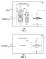
- FIGS. 3-4depict illustrative embodiments of the tunable matching network 202 of the transceiver 102 of FIG. 2 .
- the tunable matching network 202can comprise a control circuit 302 and a tunable reactive element 310 .
- the control circuit 302can comprise a DC-to-DC converter 304 , one or more digital to analog converters (DACs) 306 and one or more corresponding buffers 308 to amplify the voltage generated by each DAC.
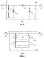
- the amplified signalcan be fed to one or more tunable reactive components 504 , 506 and 508 such as shown in FIG. 5 , which depicts a possible circuit configuration for the tunable reactive element 310 .
- the tunable reactive element 310includes three tunable capacitors 504 - 508 and an inductor 502 with a fixed inductance. Other circuit configurations are possible, and thereby contemplated by the present disclosure.
- the tunable capacitors 504 - 508can each utilize technology that enables tunability of the capacitance of said component.
- One embodiment of the tunable capacitors 504 - 508can utilize voltage or current tunable dielectric materials such as a composition of barium strontium titanate (BST).
- BSTbarium strontium titanate
- An illustration of a BST compositionis the Parascan® Tunable Capacitor.
- the tunable reactive element 310can utilize semiconductor varactors.
- Other present or next generation methods or material compositions that can support a means for a voltage or current tunable reactive elementare contemplated by the present disclosure.
- the DC-to-DC converter 304can receive a power signal such as 3 Volts from the power supply 114 of the communication device 100 in FIG. 1 .
- the DC-to-DC converter 304can use common technology to amplify this power signal to a higher range (e.g., 30 Volts) such as shown.
- the controller 106can supply digital signals to each of the DACs 306 by way of a control bus of “n” or more wires to individually control the capacitance of tunable capacitors 504 - 508 , thereby varying the collective reactance of the tunable matching network 202 .
- the control buscan be implemented with a two-wire common serial communications technology such as a Serial Peripheral Interface (SPI) bus.
- SPISerial Peripheral Interface
- the controller 106can submit serialized digital signals to configure each DAC in FIG. 3 or the switches of the tunable reactive element 404 of FIG. 4 .
- the control circuit 302 of FIG. 3can utilize common digital logic to implement the SPI bus and to direct digital signals supplied by the controller 106 to the DACs.
- the tunable matching network 202can comprise a control circuit 402 in the form of a decoder and a tunable reactive element 404 comprising switchable reactive elements such as shown in FIG. 6 .
- the controller 106can supply the control circuit 402 signals via the SPI bus which can be decoded with common Boolean or state machine logic to individually enable or disable the switching elements 602 .
- the switching elements 602can be implemented with semiconductor switches or micro-machined switches, such as utilized in micro-electromechanical systems (MEMS). By independently enabling and disabling the reactive elements (capacitor or inductor) of FIG. 6 with the switching elements 602 , the collective reactance of the tunable reactive element 404 can be varied.
- the tunability of the tunable matching networks 202 , 204provides the controller 106 a means to optimize performance parameters of the transceiver 102 such as, for example, but not limited to, transmitter power, transmitter efficiency, receiver sensitivity, power consumption of the communication device, a specific absorption rate (SAR) of energy by a human body, frequency band performance parameters, and so on.
- performance parameters of the transceiver 102such as, for example, but not limited to, transmitter power, transmitter efficiency, receiver sensitivity, power consumption of the communication device, a specific absorption rate (SAR) of energy by a human body, frequency band performance parameters, and so on.
- SARspecific absorption rate
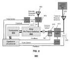
- FIG. 7depicts an exemplary embodiment of a portion of a communication device 700 (such as device 100 in FIG. 1 ) having a tunable matching network which can include, or otherwise be coupled with, a number of components such as a directional coupler, RF detectors, control circuitry and/or a tuner.
- the tunable matching networkcan include various other components in addition to, or in place of, the components shown, including components described above with respect to FIGS. 1-6 .
- a detector 702coupled to the RF line feeding the antenna 750 .
- a tunable matching network 775can be coupled to the antenna 750 and a transceiver 780 (or transmitter and/or receiver) for facilitating communication of signals between the communication device 700 and another device or system.
- the tunable matchcan be adjusted using all or a portion of the detectors for feedback to the tuning algorithm.
- Various algorithmscan be utilized for adjusting the matching network 750 , some of which are disclosed in U.S. Patent Application Publication No. 2009/0121963 filed on Nov. 14, 2007 by Greene, the disclosure of which is hereby incorporated by reference herein.
- the Greene applicationdescribes several methods utilizing Figures of Merit, which in this exemplary embodiment can be determined in whole or in part from measurements of the forward and reverse signals present at detector 701 .
- This exemplary embodimentcan also utilize detector 702 to further improve the ability of the tuning system to enable improved performance of the communication device.
- One embodiment of the algorithmcan utilize the inputs from detector 701 to establish a maximum return loss or VSWR for the matching network. This method can establish a range of impedances around the targeted impedance.
- This range of impedancesmay establish an acceptable level of performance.
- Input from detector 702can then be utilized to allow the algorithm to find an improved or best impedance within that acceptable range.
- the algorithmcould continue to modify the matching network 775 in order to increase the RF voltage detected at the antenna feed, while constraining the return loss (measured by detector 701 ) to stay within the target return loss.
- communication device 700can allow tuning for source impedances that are not 50 ohms. Additionally detector 702 allows the algorithm to minimize the insertion loss of the tunable match 775 .
- the tuning algorithmcan maintain the return loss while minimizing the current drain to determine desired tuning values.
- the tuning algorithmcan utilize various parameters for tuning the device, including output power of the transmitter, return loss, received power, current drain and/or transmitter linearity.
- Communication device 700can include one or more radiating elements 755 of the antenna 750 .
- One or more tunable elements 780can be connected directly with one or more of the radiating elements 755 to allow for tuning of the antenna 750 in conjunction with tuning of the matching network 775 .
- the tunable elements 780can be of various types as described herein, including electrically tunable capacitors.
- the number and configuration of the tunable elements 780can be varied based on a number of factors, including whether the tuning is an open loop or a closed loop process.
- all of the radiating elements 755have at least one tunable element 780 connected thereto to allow for tuning of the radiating element.
- only a portion of the radiating elements 755have a tunable element 780 connected thereto.
- FIG. 8depicts a portion of a communication device 800 (such as device 100 in FIG. 1 ) having tunable matching networks for use with a multiple antenna system.
- a communication device 800such as device 100 in FIG. 1
- there are two antennaswhich are a transmit/receive antenna 805 and a diversity reception antenna 820 .
- the antennascan be spatially diverse, pattern diverse, polarization diverse and/or adaptive array antennas.
- Tunable elements 880can be connected with radiating elements or a portion thereof of the antenna 805 .
- tunable elements 880can be connected with multiple antennas (not shown). Tunable elements 880 allow for tuning and/or detuning of one or more of the antennas, including in combination with the tuning of the matching networks 810 and/or 825 .
- the antennas of communication device 800can be part of a MIMO (multiple-input and multiple output) system.
- the multiple antennascan be utilized for improving communications, such as through switching or selecting techniques, including analyzing noise in the multiple signals and selecting the most appropriate signal.
- the multiple antennascan also be used with combining techniques where the signals can be added together, such as equal gain combining or maximal-ratio combining.
- Other techniques for utilizing multiple signals from multiple antennasare also contemplated by the exemplary embodiments, including dynamic systems that can adjust the particular techniques being utilized, such as selectively applying a switching technique and a combination technique.
- the particular position(s) of the antenna(s)can vary and can be selected based on a number of factors, including being in close enough proximity to couple RF energy with each other.
- Communication device 800can include a number of other components such as tunable matching networks which can include or otherwise be coupled with a number of components such as directional couplers, sensor ICs, bias control and other control ICs and tunable matching networks.
- the tunable matching networkscan include various other components in addition to, or in place of the components shown, including components described above with respect to FIGS. 1-7 .
- This examplealso includes a transceiver 850 of the communication device 800 that includes multiple receivers and/or transmitters for the multiple antennas 805 and 820 to serve the purpose of diversity reception.
- a first tunable matching network 810can be coupled at the input to the transmit/receive antenna 805 and a second tunable matching network 825 can be coupled to the input to the diversity reception antenna 820 .
- Both of these matching networks 810 and 825can be adjusted (e.g., tuned) to improve performance of the communication device 800 in response to changes in bands, frequencies of operation, physical use cases and/or proximity of the antennas 805 and 820 to the user or other objects which can affect the impedances presented by the antennas to the Front End Module (FEM) 860 and transceiver 850 .
- the feedback linecould be removed, such as by using the FEM to route these signals appropriately to perform these measurements (e.g., avoiding filtering out the signals).
- Tunable matching network 810can be adjusted using different methods and/or components, some of which were disclosed in U.S. Patent Application Publication No. 2009/0121963.
- a detector 830can be coupled to the device 800 so as to detect RF voltage present at the connection to the diversity reception antenna 820 . Received power levels at this point may be below ⁇ 50 dBm. Some detectors, such as a diode detector or a logarithmic amplifier, may not typically be adequate to detect such levels. However, since in this exemplary embodiment, the two antennas 805 and 820 are in the same device 800 and in proximity to each other, they can inherently couple RF energy from one antenna to the other.
- the communication device 800does not require this coupling, its presence can be utilized by the exemplary embodiments for the purposes of tuning the antenna matching networks.
- a predetermined relationship or offsetcan be applied to the matching network 825 in order to adjust the match to the receiver operating frequency.
- the tunable match on the transmit/receive antenna 805can be tuned similar to the technique described above with respect to FIG. 7 but instead of using detector 815 , detector 830 can be used to measure increases in transmitted RF power coupled to the diversity reception antenna 820 . As such, detector 815 (shown in broken lines in FIG. 8 ) can be removed from the device 800 , thereby reducing the cost and complexity. Thus, this example would tune both antennas utilizing only one detector (e.g., detector 830 ) coupled with one of the antennas (e.g., the diversity reception antenna 820 ) and without another detector coupled to the other antenna. This example relies upon a fairly constant coupling coefficient between the two antennas at any particular band, frequency and use case, and for any operation of the algorithm these may all be considered constant.
- tunable matching network 825can also be adjusted. By measuring the coupled transmitted power present at detector 830 , the tunable matching network 825 can be adjusted to increase coupled transmitter power seen at detector 830 .
- a predetermined relationship or offsetcan be applied to the matching network 825 in order to adjust the match to the receiver operating frequency.
- the tuning circuitscan be adjusted initially based on transmitter oriented metrics and then a predetermined relationship or offset can be applied to attain a desired tuning state for both transmitter and receiver operation.
- the operational metriccan be one or more of transmitter reflection loss, output power of the transmitter, current drain and/or transmitter linearity.
- TDMtime division multiplexed
- FDMfrequency division multiplexed
- a predetermined relationship(e.g., an offset, scaling factor, translation or other change or modification) can be applied to the adjustments of the variable components when switching from the transmit mode to the receive mode.
- This translationcan be a function of the values obtained while adjusting during the transmit time slot. The translation can then be removed upon return to the transmitter mode and the adjustment process is resumed.
- an adjustment or modification of the setting of the matching network in the form of a translation or some other functioncan be applied to the matching network during the receive time slot.
- the adjustmentcan be performed in multiple steps if the transmission and reception frequencies are far apart.
- a Figure of Meritcan be utilized that not only incorporates the transmit metrics, but also incorporates an element to attain a compromise between optimal transmitter and optimal receiver operation. This can be accomplished by identifying a target operation goal, such as a desired transmitter and receiver reflection loss and then identifying an operational setting that is a close compromise between the two.
- This embodimentthus can incorporate not only transmitter metrics but also tuning circuit settings or preferences into the algorithm. The tuning preferences can be empirically identified to ensure the desired operation.
- antenna 820would be receive only.
- the transceivercan transmit on antenna 805 and can receive on both antennas 805 and 820 .
- the communication device 800can obtain a metric indicating the performance of the tunable matching circuit at the receive frequency.
- the metriccan be used to tune the match to adjust the performance at the receive frequency. This can be done by measuring the level of the received signal using the receiver in the transceiver IC. This measurement is known as RSSI, received signal strength indicator.
- An RSSI measurementcan be very noisy and unstable due to highly variable impairments in the propagation channel, such as fading. These variations can be filtered using averaging. However, the amount of averaging necessary could make such a measurement prohibitively slow and not suitable as feedback for closed loop antenna tuning.
- the transmit signalis moderately coupled to the tunable match in the diversity path because the main antenna and the diversity antenna are located on the same communications device.
- the main antenna and the diversity antennamay only have 20 dB isolation in many cases.
- the transmit signal present at tunable match 825may be a much stronger and more stable signal than the receive signal present at tunable matching network 825 .
- the transmit signalcan be used to make reliable measurements that can be used for closed loop tuning.
- the transmit signalcan be measured using detector 830 .
- the detectorcan be placed between the tunable match and the transceiver. This is effectively the output of the tunable match.
- a directional coupleris not necessary for this measurement in this embodiment, and capacitive or resistive coupling may be used, as long as the detector has sufficient dynamic range.
- Other components and configurations of the componentscan also be utilized for the parameter detection, such as shown in U.S. Patent Publication No. 20090039976 by McKinzie, the disclosure of which is hereby incorporated by reference.
- maximizing the output voltage of a tunable matchcan be the equivalent to minimizing insertion loss, and for a lossless network it can be equivalent to minimizing mismatch loss.
- An alternative to using detector 830is to use the receiver itself (tuned to the transmit frequency) to measure the transmit signal. These are a few viable methods for measuring the transmit signal through the diversity tunable match. Other forms of signal detection are contemplated by the present disclosure.
- a complication with using the transmit signal for tuningcan be that it is at a different frequency than the receive signal and the objective of the tunable match in the diversity path is to adjust performance at the receive frequency.
- the tunable matching circuitis adjusted for reception performance based on transmission measurements.
- a tunable matchcan be optimized at the transmit frequency using measurements on the transmit signal and then the matching circuit can be adjusted using a predetermined relationship between the transmit settings and the receive settings to provide the desired performance at the receive frequency.
- one set of tuning valuescan be applied only during the measurement of the transmit signal.
- the other set of tuning valuesdesignated (C1RX, C2RX) can be applied in between the transmit slots, or just during the receive time slots allowing for alternate tuning during a slot which may be used to monitor other base stations or other networks.
- This embodimentdescribes two tunable capacitors, but this exemplary embodiment can apply to various numbers and types of tunable elements.
- the Rx tuning valuesare a function of the Tx tuning values. As the Tx values adaptively change throughout the iterative algorithm, the Rx values will also change, tracking the Tx values with a predetermined relationship.
- the Tx solutioncan converge at (C1TXopt, C2TXopt), and can be appropriately adjusted using the predetermined relationship to (C1RXopt, C2RXopt) to achieve the desired RX performance.
- the performance at the Rx frequencymay be degraded during the time that (C1TX, C2TX) is applied. It is desirable in this embodiment to perform the measurement as quickly as possible to minimize the Rx degradation caused by Tx tuning during the measurement.
- the Tx valuescan be applied for less than one percent of the time while still achieving adequate convergence time.
- the relationship between the TX and RX tuning solutionscan be dependent upon the bands of operation, and in the case where the receiver is tuned to monitor signals in an alternate band, then an alternate tuning solution (C1RX2, C2RX2) can be applied during that measurement.
- Another exemplary method for controlling the tuningcan be employed, which does not require setting the tunable capacitors to values optimized for transmission while performing the Tx measurement.
- the objectiveis to operate the tuning matching network at settings that optimize Rx performance. These settings are at capacitance values that are a specific amount away from the Tx optimum in a specific direction.
- An algorithmcan be utilized that will find this location in the capacitance plane without first needing to find the Tx optimum.
- the Tx levelcan change based on a number of circumstances, such as from power control commands in the transceiver or from variations in supply voltage, temperature, component tolerances, and so forth.
- a metric that can be useful in determining where the tuning matching network is operating relative to the Tx optimumis to utilize the slope, or derivative of the Tx level with respect to the value or setting of the tunable capacitors (or other types of tunable elements). If the RF voltage (Vout) present at the output of the tunable match at the TX frequency is determined, such as through use of a log detector, then the first derivatives are dVout/dC1 and dVout/dC2. These derivatives can be calculated using the finite difference of two sequential measurements. These slopes will be a function of the tunable capacitors. These slopes will not be a function of the absolute power level of the Tx signal since a log detector is being utilized.
- a log detector or its equivalentthe logarithm of the Tx voltage can be calculated prior to calculating the slope.
- the algorithmcan converge to a solution that is a specific amount away from the Tx optimum in a specific direction, in this case near the Rx optimum.
- a log detectoris a device having a logarithmic response.
- specifying the slopes alonewill not result in a unique solution (i.e., there may be multiple solutions).
- the algorithmcan resolve this situation by adding a PTC preference to the Figure of Merit.
- a tunable matchmay have many solutions that meet a Tx RL goal and a PTC preference can be included in the Figure of Merit to identify a solution that not only meets the Tx RL goal but also meets an Rx performance goal.
- a tunable matchmay have many solutions that meet a slope criteria and a PTC preference can be included in the Figure of Merit to identify a solution that not only meets the slope criteria but also meets an Rx performance goal.
- second derivatives(d 2 Vout/dC2dC1) can be utilized, which is dVout/dC2 differentiated with respect to C1.
- Specifying dVout/dC2 and d 2 Vout/dC2dC1can identify the correct or desired Rx solution from the multiple solutions.
- This exemplary methodcan include determining derivative information (e.g., one or more of a first derivative, and/or a second derivative, and/or etc.) associated with the RF voltage based on derivatives of the RF voltage and the variable capacitance values, and tuning the tunable matching network using the derivative information.
- Another exemplary embodimentcan use detector 830 of the communication device 800 in the diversity path as feedback to adjust tunable matching network 810 on the main antenna 805 .
- the tunable matching network 810 coupled with the main antennahas both transmit and receive signals, and can be optimized for Tx performance, Rx performance, and Duplex performance.
- Tx performanceVout can be maximized
- Rx solution and the Duplex solutiondVout can be included in the Figure of Merit.
- a PTC preferencemay be required to identify the optimal Rx solution but is not required to identify the optimal duplex solution, return loss, received power, current drain or transmitter linearity
- the Figure of Meritmay be constructed such that when it equals a certain value, or is minimized or maximized, the desired tuner settings are achieved.
- the Figure of Meritmay be used with a number of different optimization algorithms. For example, a more exhaustive approach may be used that evaluates the Figure of Merit at every combination of capacitor values.
- Other suitable algorithmscan also be utilized, including a simplex algorithm, a binary search algorithm, and/or a gradient algorithm.
- communication device 800can tune antennas 805 and 820 without using detectors 815 and 830 .
- the tunable matching network 810can be adjusted using several different methods, some of which were disclosed in U.S. Patent Application Publication US 2009/0121963. After the tunable matching network 810 is adjusted, the tunable matching network 825 can be adjusted. By monitoring the detector 801 coupled to the directional coupler 875 , the diversity match tuning state can be determined which adjusts the tunable matching network 825 to the transmit frequency.
- the diversity match tuning statecan be determined which tunes the diversity reception antenna 820 to the transmit frequency. This tuning state can minimize the return loss at the transmit frequency as measured at the directional coupler 875 . After finding this tuning state the tunable matching network 825 can then be adjusted (e.g., offset) appropriately for the receive frequency.
- communication device 900includes tunable element 902 for tuning antenna 901 .
- the tuningcan be in an open-loop manner, such as based on frequency and/or use case.
- Tunable element 902can be adjusted such that the antenna VSWR is in a range that can be reasonably matched by tunable matching network 908 .
- Tunable element 902can be adjusted in an open-loop manner to maximize rejection or attenuation at an unwanted frequency while maintaining the VSWR at the fundamental frequency in the range that can be reasonably matched by the tunable matching network 908 .
- the unwanted frequencymay be a harmonic or an interferer.
- Matching network 908can be tuned in a closed-loop manner, such as based on operational parameter(s) collected from detector 903 and/or directional coupler 905 having forward and reverse detectors 906 , 907 positioned between the matching network 908 and the transceiver 909 .
- communication device 1000includes tunable element 1002 for tuning antenna 1001 in an open-loop manner based on frequency and/or use case.
- Tunable element 1002can be tuned such that the antenna VSWR is in the range that can be reasonably matched by tunable matching network 1008 , and the on-antenna tuning can maximize rejection or attenuation at an unwanted frequency while maintaining a VSWR at the fundamental frequency in the range that can be reasonably matched by tunable matching network 1008 .
- the tunable matching networkcan be tuned based on metrics gathered from detector 1003 without utilizing measurements from any measuring device in between the matching network and the transceiver 1009 .
- communication device 1100includes tunable element 1102 for tuning antenna 1101 in a closed loop manner while also tuning the matching network 1108 in a closed-loop manner.
- a directional coupler 1105 having forward and reverse detectors 1106 , 1107can be connected between the matching network 1108 and a transceiver 1109 for obtaining operational parameter(s) for performing the closed loop tuning of element(s) 1102 and matching network 1108 .
- Tuningcan be performed in this embodiment without obtaining measurements from a measuring component in proximity to the antenna.
- communication device 1200includes tunable element 1202 for tuning antenna 1201 in a closed loop manner based on maintaining the RF voltage present at detector 1203 in a preset range relative to the transmit power. This can establish an antenna impedance that is in the range that can be reasonably matched by tunable matching network 1208 .
- Matching network 1208can be tuned in a closed loop manner based on operational parameter(s) obtained using directional coupler 1205 having forward and reverse detectors 1206 , 1207 coupled with the device 1200 between the matching network and the transceiver 1209 .
- communication device 1300includes tunable element 1302 for tuning antenna 1301 in a closed loop manner based on the RF voltage obtained at detector 1303 , such as maintaining the RF voltage in a preset range relative to the transmit power.
- Matching network 1308can be tuned in a closed loop manner based on operational parameter(s) obtained using detector 1303 without obtaining measurements from any measuring components coupled between the matching network 1308 and the transceiver 1309 .
- communication device 1400includes tunable element 1402 for tuning antenna 1401 in a closed loop manner by placing the antenna VSWR detected using directional coupler 1410 with forward and reverse detectors 1411 , 1412 in a preset range. This will establish an antenna VSWR that is in the range which can then be reasonably matched by tunable matching network 1408 . Within the acceptable range of the antenna VSWR, the solution can be biased using a tuning preference for on-antenna element 1402 to achieve a second criteria. Matching for the element 1402 can be performed at the Rx frequency and/or based on achieving linearity.
- the matching network 1408can be tuned in a closed loop manner based on operational parameter(s) obtained from the directional coupler 1405 having forward and reverse detectors 1406 , 1407 positioned between the matching network and the transceiver 1409 .
- communication device 1500includes tunable element 1502 for tuning antenna 1501 in a closed loop manner by placing the antenna VSWR detected using directional coupler 1510 with forward and reverse detectors 1511 , 1512 in a preset range. This will establish an antenna VSWR that is in the range which can then be reasonably matched by tunable matching network 1508 . Within the acceptable range of the antenna VSWR, the solution can be biased using a tuning preference for on-antenna tunable element 1502 to achieve a second criteria. Matching for the element 1502 can be performed at the Rx frequency and/or based on achieving linearity.
- the matching network 1508can be tuned in a closed loop manner based on operational parameter(s) obtained from the detector 1503 coupled in proximity to the antenna 1501 without obtaining measurements from any measuring component positioned between the matching network and the transceiver 1509 .
- communication device 1600includes an antenna 1601 that includes two radiating elements which cover different frequency ranges, tunable element 1602 and tunable element 1610 for tuning antenna 1601 .
- Tunable element 1602can primarily affect a first frequency range or band and tunable element 1610 can primarily affect the second frequency range or band of the antenna 1601 .
- Tunable element 1602can be adjusted in an open-loop manner based on frequency and/or use case. Tunable element 1602 can be adjusted such that the antenna VSWR as determined or otherwise estimated from metrics of the detector 1603 and with knowledge of the transmitter output power is in a range that can be reasonably matched by tunable matching network 1608 .
- Tunable element 1610can be adjusted in an open-loop manner to maximize rejection or attenuation at an unwanted frequency while maintaining a VSWR at the fundamental frequency in the range that can be reasonably matched by tunable matching network 1608 .
- the unwanted frequencymay be a harmonic, such as in the High Band, while the fundamental (TX & RX) frequencies can be in the Low Band.
- Matching network 1608can be tuned in a closed loop manner utilizing operational parameter(s) obtained from the directional coupler 1605 having forward and reverse detectors 1606 , 1607 coupled between the matching network and the transceiver 1609 .
- Another embodimentprovides for tuning one or more of the antennas of a communication device.
- simply maximizing the over the air efficiency of all the antennasmay not accomplish the best overall performance of the communication system.
- the isolation or de-correlation between antennas in a small handsetcan also be a key parameter in defining the overall performance in certain instances.
- a control method that considers the efficiency of both antennas and the isolation between themcan be advantageous.
- the antennascan be tuned so as to reduce coupling between the antennas without degrading the efficiency of either antenna, or to degrade efficiency minimally such that overall system performance is enhanced.
- the couplingmay be reduced or otherwise kept to a minimum in spite of antenna proximity.
- Other parameters other than antenna cross-couplingmay also be optimized to improve overall performance of the system, such as in a MIMO system where there can be simultaneously multiple output antennas and multiple input antennas.
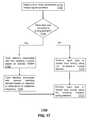
- FIG. 17depicts an exemplary method 1700 operating in portions of one or more of the devices of FIGS. 1-16 .
- Method 1700can be utilized with communication devices of various configurations, including multiple antenna devices.
- Method 1700can begin with step 1702 by detecting one or more parameters of the communication device, such as parameters associated with transmitting that are obtained through use of measuring components including a detector and/or a directional coupler.
- the number and positioning of the measuring componentscan vary and can be in proximity to the antenna and/or between a matching network and a transceiver.
- step 1704it can be determined whether there are multiple on-antenna tuning elements. If there are more than one such tuning elements then in step 1706 tuning elements associated with a radiating element(s) can be tuned based on a desired VSWR at a frequency of operation. In step 1708 , tuning elements associated with another radiating element(s) can be tuned based on a different factor, such as a rejection or attenuation of an unwanted frequency. If on the other hand, there is only one on-antenna tuning element and/or the tuning elements are only connected with one of the radiating elements of the antenna then method 1700 can proceed to step 1710 where the on-antenna tuning element(s) is tuned using an open loop and/or closed loop process.
- the open loop processcan utilize various factors to determine tuning, including use case, operating frequency, proximity information accelerometer/position information, and so forth.
- the closed loop processcan utilize various factors to determine tuning, including RF voltage, return loss, received power, current drain and/or transmitter linearity
- tuningcan be performed utilizing the matching network.
- the tuning of the matching networkcan be an open loop and/or closed loop process, including using one or more of the factors described above with respect to the open and closed loop processes that can tune the on-antenna tuning elements.
- the timing of the tuning utilizing the matching networkcan vary, including being performed simultaneously with tuning of the on-antenna tuning elements, after tuning of the on-antenna tuning elements and/or before tuning of the on-antenna tuning elements.
- Method 1700can be an iterative process that tunes the on-antenna tuning elements and/or the matching network.
- the tuning of the matching network(s)can be performed in combination with look-up tables such as shown in FIG. 18 .
- one or more desirable performance characteristics of a communication device 100can be defined in the form of Figures of Merits (FOMs), the communication device can be adapted to find a range of tuning states that achieve the desired FOMs by sweeping a mathematical model in fine increments to find global optimal performance with respect to the desired FOMs.
- look-up table 1800can be indexed (e.g., by the controller 106 of the communication device 100 of FIG. 1 ) during operation according to band and/or use case.
- detector 830may include a directional coupler for the diversity antenna to compensate for out-of-band impedance of the Rx filter that may create a very high standing wave on the feed line and put voltage nulls at unpredictable places on the line (including at the base of the antenna).
- combinations of open and closed loop processescan be utilized for tuning of one or more of the tunable elements of the antenna and/or the matching network.
- a tunable element of the antennacan be tuned in part with a closed loop process based on an operational parameter of the communication system and in part with an open loop process based on a use case and/or location information of the communication device.
- the use of closed loop and open loop processescan be alternated or otherwise arranged in being applied to a particular tunable element, such as initially applying an open loop process but then later applying a closed loop process, including switching from an open loop to a closed loop process based on operational parameters of the communication device.
- the matching networkcan be tuned in whole or in part using an open loop process, such as based on a use case provided in a look-up table and/or based on location information associated with the communication device.
- the exemplary embodimentscan employ open loop tuning processes, such as at the on-antenna tunable element and/or at the matching network.
- the use casescan include a number of different states or status associated with the communication device, such as flip-open, flip-closed, slider-in, slider-out (e.g., Qwerty or numeric Keypad), speaker-phone on, speaker-phone off, hands-free operation, antenna up, antenna down, other communication modes on or off (e.g., Bluetooth/WiFi/GPS), particular frequency band, and/or transmit or receive mode.
- the use casecan be based on object or surface proximity detection (e.g., a user's hand or a table).
- the open loop processcan take into account other information, such as associated with a particular location (e.g., in a building or in a city surrounded by buildings), as well as an indication of being out of range.
- the exemplary embodimentscan utilize combinations of open loop and closed loop processes, such as tuning a tunable element based on both a use case and a measured operating parameter (e.g., measured by a detector in proximity to the antenna and/or measured by a directional coupler between the matching network and the transceiver).
- the tuningcan utilize one process and then switch to another process, such as using closed loop tuning and then switching to open loop tuning based on particular factors associated with the communication device.
- the use casecan be based on the knowledge of transmitter power level setting and receiver received signal strength, current drain, accelerometer direction/orientation, and any other information that is available within the device (e.g., a handset, tablet, or other wireless communication device) indicative of operating modes or use case.
- Low Band (LB) radiating element(s) and High Band (HB) radiating element(s)can be utilized with the antenna, where at least one tunable element is associated with the LB radiating element is tuned based on a desired Voltage Standing Wave Ratio (VSWR) associated with the antenna, and wherein at least another tunable elements that is associated with the HB radiating element is tuned based on a different performance metric.
- the different performance metriccan be based on attenuation of an undesired frequency.
- the undesired frequencycan be a harmonic frequency or can be associated with an interferer.
- Methodologies and/or components that are described herein with respect to tuning of one tunable elementcan also be utilized with respect to tuning of other tunable elements.
- derivative information utilized for tuning the matching networkcan be used for tuning of on-antenna tunable elements.
- FIG. 19depicts an exemplary diagrammatic representation of a machine in the form of a computer system 1900 within which a set of instructions, when executed, may cause the machine to perform any one or more of the methodologies discussed above.
- the machineoperates as a standalone device.
- the machinemay be connected (e.g., using a network) to other machines.
- the machinemay operate in the capacity of a server or a client user machine in server-client user network environment, or as a peer machine in a peer-to-peer (or distributed) network environment.
- the machinemay comprise a server computer, a client user computer, a personal computer (PC), a tablet PC, a laptop computer, a desktop computer, a control system, a network router, switch or bridge, or any machine capable of executing a set of instructions (sequential or otherwise) that specify actions to be taken by that machine.
- a device of the present disclosureincludes broadly any electronic device that provides voice, video or data communication.
- the term “machine”shall also be taken to include any collection of machines that individually or jointly execute a set (or multiple sets) of instructions to perform any one or more of the methodologies discussed herein.
- the computer system 1900may include a processor 1902 (e.g., a central processing unit (CPU), a graphics processing unit (GPU, or both), a main memory 1904 and a static memory 1906 , which communicate with each other via a bus 1908 .
- the computer system 1900may further include a video display unit 1910 (e.g., a liquid crystal display (LCD), a flat panel, a solid state display, or a cathode ray tube (CRT)).
- the computer system 1900may include an input device 1912 (e.g., a keyboard), a cursor control device 1914 (e.g., a mouse), a disk drive unit 1916 , a signal generation device 1918 (e.g., a speaker or remote control) and a network interface device 1920 .
- an input device 1912e.g., a keyboard
- a cursor control device 1914e.g., a mouse
- a disk drive unit 1916e.g., a disk drive unit
- a signal generation device 1918e.g., a speaker or remote control
- the disk drive unit 1916may include a machine-readable medium 1922 on which is stored one or more sets of instructions (e.g., software 1924 ) embodying any one or more of the methodologies or functions described herein, including those methods illustrated above.
- the instructions 1924may also reside, completely or at least partially, within the main memory 1904 , the static memory 1906 , and/or within the processor 1902 during execution thereof by the computer system 1900 .
- the main memory 1904 and the processor 1902also may constitute machine-readable media.
- Dedicated hardware implementationsincluding, but not limited to, application specific integrated circuits, programmable logic arrays and other hardware devices can likewise be constructed to implement the methods described herein.
- Applicationsthat may include the apparatus and systems of various embodiments broadly include a variety of electronic and computer systems. Some embodiments implement functions in two or more specific interconnected hardware modules or devices with related control and data signals communicated between and through the modules, or as portions of an application-specific integrated circuit.
- the example systemis applicable to software, firmware, and hardware implementations.
- the methods described hereinare intended for operation as software programs running on a computer processor.
- software implementationscan include, but not limited to, distributed processing or component/object distributed processing, parallel processing, or virtual machine processing can also be constructed to implement the methods described herein.
- the present disclosurecontemplates a machine readable medium containing instructions 1924 , or that which receives and executes instructions 1924 from a propagated signal so that a device connected to a network environment 1926 can send or receive voice, video or data, and to communicate over the network 1926 using the instructions 1924 .
- the instructions 1924may further be transmitted or received over a network 1926 via the network interface device 1920 .
- machine-readable medium 1922is shown in an example embodiment to be a single medium, the term “machine-readable medium” should be taken to include a single medium or multiple media (e.g., a centralized or distributed database, and/or associated caches and servers) that store the one or more sets of instructions.
- the term “machine-readable medium”shall also be taken to include any medium that is capable of storing, encoding or carrying a set of instructions for execution by the machine and that cause the machine to perform any one or more of the methodologies of the present disclosure.
- machine-readable mediumshall accordingly be taken to include, but not be limited to: solid-state memories such as a memory card or other package that houses one or more read-only (non-volatile) memories, random access memories, or other re-writable (volatile) memories; magneto-optical or optical medium such as a disk or tape; and/or a digital file attachment to e-mail or other self-contained information archive or set of archives is considered a distribution medium equivalent to a tangible storage medium. Accordingly, the disclosure is considered to include any one or more of a machine-readable medium or a distribution medium, as listed herein and including art-recognized equivalents and successor media, in which the software implementations herein are stored.
- inventive subject mattermay be referred to herein, individually and/or collectively, by the term “invention” merely for convenience and without intending to voluntarily limit the scope of this application to any single invention or inventive concept if more than one is in fact disclosed.
- inventive conceptmerely for convenience and without intending to voluntarily limit the scope of this application to any single invention or inventive concept if more than one is in fact disclosed.
Landscapes
- Engineering & Computer Science (AREA)
- Computer Networks & Wireless Communication (AREA)
- Signal Processing (AREA)
- Transceivers (AREA)
Abstract
Description
Claims (22)
Priority Applications (13)
| Application Number | Priority Date | Filing Date | Title |
|---|---|---|---|
| US13/108,463US8594584B2 (en) | 2011-05-16 | 2011-05-16 | Method and apparatus for tuning a communication device |
| CA2835432ACA2835432C (en) | 2011-05-16 | 2012-05-15 | Method and apparatus for tuning a communication device |
| CA2836419ACA2836419C (en) | 2011-05-16 | 2012-05-15 | Method and apparatus for tuning a communication device |
| CN201280032857.0ACN103975482B (en) | 2011-05-16 | 2012-05-15 | Method and apparatus for tuning a communication device |
| EP17155774.7AEP3188309A1 (en) | 2011-05-16 | 2012-05-15 | Method and apparatus for tuning a communication device |
| EP12723569.5AEP2710672A1 (en) | 2011-05-16 | 2012-05-15 | Method and apparatus for tuning a communication device |
| EP12724250.1AEP2710669B1 (en) | 2011-05-16 | 2012-05-15 | Method and apparatus for tuning a communication device |
| PCT/US2012/037942WO2012158693A1 (en) | 2011-05-16 | 2012-05-15 | Method and apparatus for tuning a communication device |
| PCT/US2012/037943WO2012158694A1 (en) | 2011-05-16 | 2012-05-15 | Method and apparatus for tuning a communication device |
| CN201280032976.6ACN103931051B (en) | 2011-05-16 | 2012-05-15 | For the method and apparatus tuning communication equipment |
| TW101117467ATWI552535B (en) | 2011-05-16 | 2012-05-16 | Method and apparatus for tuning a communication device |
| US14/060,155US9716311B2 (en) | 2011-05-16 | 2013-10-22 | Method and apparatus for tuning a communication device |
| US15/632,021US10218070B2 (en) | 2011-05-16 | 2017-06-23 | Method and apparatus for tuning a communication device |
Applications Claiming Priority (1)
| Application Number | Priority Date | Filing Date | Title |
|---|---|---|---|
| US13/108,463US8594584B2 (en) | 2011-05-16 | 2011-05-16 | Method and apparatus for tuning a communication device |
Related Child Applications (1)
| Application Number | Title | Priority Date | Filing Date |
|---|---|---|---|
| US14/060,155ContinuationUS9716311B2 (en) | 2011-05-16 | 2013-10-22 | Method and apparatus for tuning a communication device |
Publications (2)
| Publication Number | Publication Date |
|---|---|
| US20120295554A1 US20120295554A1 (en) | 2012-11-22 |
| US8594584B2true US8594584B2 (en) | 2013-11-26 |
Family
ID=47175274
Family Applications (3)
| Application Number | Title | Priority Date | Filing Date |
|---|---|---|---|
| US13/108,463Active2032-03-22US8594584B2 (en) | 2011-05-16 | 2011-05-16 | Method and apparatus for tuning a communication device |
| US14/060,155Active2032-04-28US9716311B2 (en) | 2011-05-16 | 2013-10-22 | Method and apparatus for tuning a communication device |
| US15/632,021Active2031-06-13US10218070B2 (en) | 2011-05-16 | 2017-06-23 | Method and apparatus for tuning a communication device |
Family Applications After (2)
| Application Number | Title | Priority Date | Filing Date |
|---|---|---|---|
| US14/060,155Active2032-04-28US9716311B2 (en) | 2011-05-16 | 2013-10-22 | Method and apparatus for tuning a communication device |
| US15/632,021Active2031-06-13US10218070B2 (en) | 2011-05-16 | 2017-06-23 | Method and apparatus for tuning a communication device |
Country Status (2)
| Country | Link |
|---|---|
| US (3) | US8594584B2 (en) |
| TW (1) | TWI552535B (en) |
Cited By (53)
| Publication number | Priority date | Publication date | Assignee | Title |
|---|---|---|---|---|
| US20120331436A1 (en)* | 2011-09-06 | 2012-12-27 | Variable Z0, Ltd. | Variable z0 antenna device design system and method |
| US20130331042A1 (en)* | 2012-06-08 | 2013-12-12 | Qualcomm Incorporated | Control of transmit power and adjustment of antenna tuning network of a wireless device |
| US8896391B2 (en) | 2000-07-20 | 2014-11-25 | Blackberry Limited | Tunable microwave devices with auto-adjusting matching circuit |
| US8942657B2 (en) | 2006-01-14 | 2015-01-27 | Blackberry Limited | Adaptive matching network |
| US8948889B2 (en) | 2012-06-01 | 2015-02-03 | Blackberry Limited | Methods and apparatus for tuning circuit components of a communication device |
| US8957742B2 (en) | 2008-09-24 | 2015-02-17 | Blackberry Limited | Methods for tuning an adaptive impedance matching network with a look-up table |
| US9020446B2 (en) | 2009-08-25 | 2015-04-28 | Blackberry Limited | Method and apparatus for calibrating a communication device |
| US9026062B2 (en) | 2009-10-10 | 2015-05-05 | Blackberry Limited | Method and apparatus for managing operations of a communication device |
| US9119152B2 (en) | 2007-05-07 | 2015-08-25 | Blackberry Limited | Hybrid techniques for antenna retuning utilizing transmit and receive power information |
| US9130543B2 (en) | 2006-11-08 | 2015-09-08 | Blackberry Limited | Method and apparatus for adaptive impedance matching |
| US9231643B2 (en) | 2011-02-18 | 2016-01-05 | Blackberry Limited | Method and apparatus for radio antenna frequency tuning |
| US20160020732A1 (en)* | 2014-05-28 | 2016-01-21 | Skyworks Solutions, Inc. | Systems and methods related to switchable output stages in power amplifiers |
| US9246223B2 (en) | 2012-07-17 | 2016-01-26 | Blackberry Limited | Antenna tuning for multiband operation |
| US20160043776A1 (en)* | 2008-12-23 | 2016-02-11 | Keyssa, Inc. | Contactless replacement for cabled standards-based interfaces |
| US9263806B2 (en) | 2010-11-08 | 2016-02-16 | Blackberry Limited | Method and apparatus for tuning antennas in a communication device |
| US20160134016A1 (en)* | 2013-06-26 | 2016-05-12 | Cavendish Kinetics, Inc. | Antenna efficiency enhancement by active detuning of diversity antenna |
| US9350405B2 (en) | 2012-07-19 | 2016-05-24 | Blackberry Limited | Method and apparatus for antenna tuning and power consumption management in a communication device |
| US9362891B2 (en) | 2012-07-26 | 2016-06-07 | Blackberry Limited | Methods and apparatus for tuning a communication device |
| US9374113B2 (en) | 2012-12-21 | 2016-06-21 | Blackberry Limited | Method and apparatus for adjusting the timing of radio antenna tuning |
| US9386542B2 (en) | 2013-09-19 | 2016-07-05 | Google Technology Holdings, LLC | Method and apparatus for estimating transmit power of a wireless device |
| US9401750B2 (en) | 2010-05-05 | 2016-07-26 | Google Technology Holdings LLC | Method and precoder information feedback in multi-antenna wireless communication systems |
| US9413066B2 (en) | 2012-07-19 | 2016-08-09 | Blackberry Limited | Method and apparatus for beam forming and antenna tuning in a communication device |
| US9419581B2 (en) | 2006-11-08 | 2016-08-16 | Blackberry Limited | Adaptive impedance matching apparatus, system and method with improved dynamic range |
| US9450637B2 (en) | 2010-04-20 | 2016-09-20 | Blackberry Limited | Method and apparatus for managing interference in a communication device |
| US9473216B2 (en) | 2011-02-25 | 2016-10-18 | Blackberry Limited | Method and apparatus for tuning a communication device |
| US9478847B2 (en) | 2014-06-02 | 2016-10-25 | Google Technology Holdings LLC | Antenna system and method of assembly for a wearable electronic device |
| US9491007B2 (en) | 2014-04-28 | 2016-11-08 | Google Technology Holdings LLC | Apparatus and method for antenna matching |
| US9548716B2 (en) | 2010-03-22 | 2017-01-17 | Blackberry Limited | Method and apparatus for adapting a variable impedance network |
| US9549290B2 (en) | 2013-12-19 | 2017-01-17 | Google Technology Holdings LLC | Method and apparatus for determining direction information for a wireless device |
| US9591508B2 (en) | 2012-12-20 | 2017-03-07 | Google Technology Holdings LLC | Methods and apparatus for transmitting data between different peer-to-peer communication groups |
| US9647742B2 (en) | 2014-07-30 | 2017-05-09 | Google Technology Holdings LLC | Antenna architecture and operational method for RF test connector reduction |
| US9698748B2 (en) | 2007-04-23 | 2017-07-04 | Blackberry Limited | Adaptive impedance matching |
| US9716311B2 (en) | 2011-05-16 | 2017-07-25 | Blackberry Limited | Method and apparatus for tuning a communication device |
| US9735854B2 (en)* | 2016-01-18 | 2017-08-15 | Qorvo Us, Inc. | Systems for antenna swapping switching and methods of operation thereof |
| US9793972B1 (en) | 2016-04-04 | 2017-10-17 | Qorvo Us, Inc. | Multiple-input multiple-output (MIMO) antenna swapping circuit |
| US9813139B2 (en) | 2015-07-09 | 2017-11-07 | Mojoose, Inc. | Automatic RF antenna switching for an electronic communication device |
| US9813262B2 (en) | 2012-12-03 | 2017-11-07 | Google Technology Holdings LLC | Method and apparatus for selectively transmitting data using spatial diversity |
| US9853363B2 (en) | 2012-07-06 | 2017-12-26 | Blackberry Limited | Methods and apparatus to control mutual coupling between antennas |
| US9979531B2 (en) | 2013-01-03 | 2018-05-22 | Google Technology Holdings LLC | Method and apparatus for tuning a communication device for multi band operation |
| US10003393B2 (en) | 2014-12-16 | 2018-06-19 | Blackberry Limited | Method and apparatus for antenna selection |
| US10142728B2 (en) | 2008-12-23 | 2018-11-27 | Keyssa, Inc. | Contactless audio adapter, and methods |
| US10163574B2 (en) | 2005-11-14 | 2018-12-25 | Blackberry Limited | Thin films capacitors |
| US10229697B2 (en) | 2013-03-12 | 2019-03-12 | Google Technology Holdings LLC | Apparatus and method for beamforming to obtain voice and noise signals |
| USRE47412E1 (en) | 2007-11-14 | 2019-05-28 | Blackberry Limited | Tuning matching circuits for transmitter and receiver bands as a function of the transmitter metrics |
| US10305453B2 (en)* | 2017-09-11 | 2019-05-28 | Apple Inc. | Electronic device antennas having multiple operating modes |
| US10375221B2 (en) | 2015-04-30 | 2019-08-06 | Keyssa Systems, Inc. | Adapter devices for enhancing the functionality of other devices |
| US10404295B2 (en) | 2012-12-21 | 2019-09-03 | Blackberry Limited | Method and apparatus for adjusting the timing of radio antenna tuning |
| US20200088773A1 (en)* | 2018-09-17 | 2020-03-19 | Infineon Technologies Ag | RF Impedance Measurement and Tuning System |
| US10624091B2 (en) | 2011-08-05 | 2020-04-14 | Blackberry Limited | Method and apparatus for band tuning in a communication device |
| US11057130B2 (en) | 2017-01-02 | 2021-07-06 | Mojoose, Inc. | Automatic signal strength indicator and automatic antenna switch |
| US20220052721A1 (en)* | 2018-09-17 | 2022-02-17 | Bayerische Motoren Werke Aktiengesellschaft | Broadcast Receiving Device of a Motor Vehicle |
| US20230168722A1 (en)* | 2021-11-26 | 2023-06-01 | Intel Corporation | Mobile communication device |
| US11791852B2 (en) | 2021-04-12 | 2023-10-17 | Nxp Usa, Inc. | Antenna tuner for a beamforming antenna array |
Families Citing this family (54)
| Publication number | Priority date | Publication date | Assignee | Title |
|---|---|---|---|---|
| US8194451B2 (en) | 2007-11-29 | 2012-06-05 | Zeno Semiconductor, Inc. | Memory cells, memory cell arrays, methods of using and methods of making |
| US10403361B2 (en) | 2007-11-29 | 2019-09-03 | Zeno Semiconductor, Inc. | Memory cells, memory cell arrays, methods of using and methods of making |
| US8014200B2 (en) | 2008-04-08 | 2011-09-06 | Zeno Semiconductor, Inc. | Semiconductor memory having volatile and multi-bit, non-volatile functionality and methods of operating |
| US8626083B2 (en)* | 2011-05-16 | 2014-01-07 | Blackberry Limited | Method and apparatus for tuning a communication device |
| US9564676B2 (en)* | 2011-06-30 | 2017-02-07 | Google Technology Holdings LLC | System and methods for adaptive antenna optimization |
| US9106283B2 (en)* | 2011-11-07 | 2015-08-11 | Epcos Ag | Multi antenna communication device with improved tuning ability |
| US9144051B2 (en)* | 2012-02-15 | 2015-09-22 | Microchip Technology Incorporated | Proximity detection using an antenna and directional coupler switch |
| US9263793B2 (en)* | 2012-04-20 | 2016-02-16 | Ethertronics, Inc. | Multi-band communication system with isolation and impedance matching provision |
| US20130285873A1 (en)* | 2012-04-20 | 2013-10-31 | Ethertronics, Inc. | Multi-band communication system with isolation and impedance matching provision |
| US8972818B2 (en)* | 2012-10-05 | 2015-03-03 | Qualcomm Incorporated | Algorithm for optimal usage of external memory tuning sequence |
| EP2722996B1 (en) | 2012-10-22 | 2014-12-17 | BlackBerry Limited | Method and apparatus for radio frequency tuning utilizing a determined use case |
| US9871544B2 (en) | 2013-05-29 | 2018-01-16 | Microsoft Technology Licensing, Llc | Specific absorption rate mitigation |
| US10893488B2 (en) | 2013-06-14 | 2021-01-12 | Microsoft Technology Licensing, Llc | Radio frequency (RF) power back-off optimization for specific absorption rate (SAR) compliance |
| US9407335B2 (en) | 2013-08-06 | 2016-08-02 | Google Technology Holdings LLC | Method and wireless communication device for using an antenna as a sensor device in guiding selection of optimized tuning networks |
| CN203466294U (en)* | 2013-08-22 | 2014-03-05 | 深圳富泰宏精密工业有限公司 | Adjustable antenna and wireless communication device therewith |
| US9960791B2 (en) | 2013-12-12 | 2018-05-01 | Ethertronics, Inc. | RF integrated circuit with tunable component and memory |
| US10044095B2 (en) | 2014-01-10 | 2018-08-07 | Microsoft Technology Licensing, Llc | Radiating structure with integrated proximity sensing |
| US9813997B2 (en) | 2014-01-10 | 2017-11-07 | Microsoft Technology Licensing, Llc | Antenna coupling for sensing and dynamic transmission |
| US9595994B2 (en)* | 2014-02-10 | 2017-03-14 | Qualcomm Incorporated | Mode-based antenna tuning |
| US10141655B2 (en) | 2014-02-25 | 2018-11-27 | Ethertronics, Inc. | Switch assembly with integrated tuning capability |
| US9843307B2 (en) | 2014-05-12 | 2017-12-12 | Altair Semiconductor Ltd. | Passive automatic antenna tuning based on received-signal analysis |
| US9438279B2 (en)* | 2014-05-12 | 2016-09-06 | Altair Semiconductor Ltd. | Wireless device with adaptively-tunable electrically-small antennas |
| US9791490B2 (en)* | 2014-06-09 | 2017-10-17 | Apple Inc. | Electronic device having coupler for tapping antenna signals |
| US9769769B2 (en)* | 2014-06-30 | 2017-09-19 | Microsoft Technology Licensing, Llc | Detecting proximity using antenna feedback |
| US9785174B2 (en) | 2014-10-03 | 2017-10-10 | Microsoft Technology Licensing, Llc | Predictive transmission power control for back-off |
| AU2017100283B4 (en)* | 2014-10-03 | 2017-06-29 | Apple Inc. | Wireless electronic device with calibrated reflectometer |
| US9594147B2 (en) | 2014-10-03 | 2017-03-14 | Apple Inc. | Wireless electronic device with calibrated reflectometer |
| CN107078711A (en)* | 2014-10-14 | 2017-08-18 | 华为技术有限公司 | Systems and methods for suppressing leakage in full-duplex systems |
| US9871545B2 (en) | 2014-12-05 | 2018-01-16 | Microsoft Technology Licensing, Llc | Selective specific absorption rate adjustment |
| CN105789887B (en)* | 2014-12-17 | 2019-02-26 | 联芯科技有限公司 | The device and implementation method of mutual interference between a kind of reduction wireless radio frequency modules |
| EP3298653B1 (en) | 2015-05-18 | 2022-03-02 | Cavendish Kinetics, Inc. | Method and apparatus of maintaining constant antenna resonant frequency and impedance match in the presence of environmental changes and head/hand effect using variable reactance antenna aperture tuners |
| US10079432B2 (en)* | 2015-09-24 | 2018-09-18 | Honeywell International Inc. | Parameter scanned tunable antenna |
| US10013038B2 (en) | 2016-01-05 | 2018-07-03 | Microsoft Technology Licensing, Llc | Dynamic antenna power control for multi-context device |
| US10110261B2 (en)* | 2016-04-22 | 2018-10-23 | The Charles Stark Draper Laboratory, Inc. | Transceiver system to adapt to antenna de-tuning |
| US10431889B2 (en)* | 2016-04-22 | 2019-10-01 | The Charles Stark Draper Laboratory, Inc. | Low-loss compact transmit impedance matching tuning technique |
| US10312582B2 (en) | 2016-05-27 | 2019-06-04 | Futurewei Technologies, Inc. | Closed loop aperture tunable antenna |
| EP3514990B1 (en)* | 2016-10-11 | 2020-12-09 | Huawei Technologies Co., Ltd. | Radio frequency system |
| US10461406B2 (en) | 2017-01-23 | 2019-10-29 | Microsoft Technology Licensing, Llc | Loop antenna with integrated proximity sensing |
| US10224974B2 (en) | 2017-03-31 | 2019-03-05 | Microsoft Technology Licensing, Llc | Proximity-independent SAR mitigation |
| CN110463084A (en)* | 2017-03-31 | 2019-11-15 | 英特尔Ip公司 | Adjust the parameters of the receiver system |
| KR101919317B1 (en)* | 2017-09-07 | 2018-11-16 | 고려대학교 산학협력단 | MULTI-BAND SPNT SWITCH USING VARIABLE λ/4 TRANSMISSION LINE, AND SWITCH MATRIX AND TRANSMITTING AND RECEIVING SYSTEM COMORISING THE SPNT SWITCH |
| US11811138B2 (en) | 2018-02-22 | 2023-11-07 | University Of Massachusetts | Antenna hardware and control |
| US10736050B2 (en) | 2018-07-09 | 2020-08-04 | Honeywell International Inc. | Adjusting transmission power of an antenna based on an object causing path loss in a communication link |
| CN110911804B (en)* | 2018-09-17 | 2023-03-24 | 中兴通讯股份有限公司 | Antenna adjusting method and device and computer storage medium |
| KR102553982B1 (en) | 2018-09-19 | 2023-07-11 | 현대자동차주식회사 | Vehicle, control method thereof and antenna for vehicle |
| US10903915B1 (en)* | 2018-12-18 | 2021-01-26 | ZaiNar, Inc. | System for generating accurate reference signals for time-of-arrival based time synchronization |
| US11172380B2 (en)* | 2019-01-24 | 2021-11-09 | Apple Inc. | Systems and methods for real-time adaptive antenna frequency response optimization for multi-carrier wireless systems |
| EP3731339A1 (en) | 2019-04-23 | 2020-10-28 | NXP USA, Inc. | Impedance compensation system with microstrip and slotline coupling and controllable capacitance |
| FR3099968B1 (en)* | 2019-08-13 | 2021-07-23 | Tekcem | Method for automatic tuning of tunable passive antennas and a tuning unit, and apparatus for radio communication using this method |
| US11296670B2 (en)* | 2020-01-23 | 2022-04-05 | Qualcomm Incorporated | Impedance matching transceiver |
| IL310122A (en) | 2021-07-21 | 2024-03-01 | Ii Donald P Labriola | Compact portable frequency adjustable antenna |
| CN113783634B (en)* | 2021-08-25 | 2023-06-06 | Oppo广东移动通信有限公司 | Method and device for adjusting electromagnetic wave specific absorption rate, medium and electronic equipment |
| DE102021129836A1 (en)* | 2021-11-16 | 2023-05-17 | Diehl Metering Systems Gmbh | Procedure for antenna tuning |
| US20250300679A1 (en)* | 2024-03-20 | 2025-09-25 | Qualcomm Incorporated | Multi-stage impedance tuning in radio frequency transmitter |
Citations (297)
| Publication number | Priority date | Publication date | Assignee | Title |
|---|---|---|---|---|
| DE1614655U (en) | 1950-06-16 | 1950-10-12 | Accumulatoren Fabrik Orion G M | LIQUID-TIGHT SEALED SMALL ACCUMULATOR. |
| US2745067A (en) | 1951-06-28 | 1956-05-08 | True Virgil | Automatic impedance matching apparatus |
| US3117279A (en) | 1962-06-04 | 1964-01-07 | Collins Radio Co | Automatically controlled antenna tuning and loading system |
| US3160832A (en) | 1961-12-22 | 1964-12-08 | Collins Radio Co | Automatic coupling and impedance matching network |
| US3390337A (en) | 1966-03-15 | 1968-06-25 | Avco Corp | Band changing and automatic tuning apparatus for transmitter tau-pad output filter |
| US3443231A (en) | 1966-04-27 | 1969-05-06 | Gulf General Atomic Inc | Impedance matching system |
| US3509500A (en) | 1966-12-05 | 1970-04-28 | Avco Corp | Automatic digital tuning apparatus |
| US3571716A (en) | 1968-04-16 | 1971-03-23 | Motorola Inc | Electronically tuned antenna system |
| US3590385A (en) | 1969-07-25 | 1971-06-29 | Avco Corp | Semi-automatic tuning circuit for an antenna coupler |
| US3601717A (en) | 1969-11-20 | 1971-08-24 | Gen Dynamics Corp | System for automatically matching a radio frequency power output circuit to a load |
| US3794941A (en) | 1972-05-08 | 1974-02-26 | Hughes Aircraft Co | Automatic antenna impedance tuner including digital control circuits |
| US3919644A (en) | 1970-02-02 | 1975-11-11 | Gen Dynamics Corp | Automatic antenna coupler utilizing system for measuring the real part of the complex impedance or admittance presented by an antenna or other network |
| US3990024A (en) | 1975-01-06 | 1976-11-02 | Xerox Corporation | Microstrip/stripline impedance transformer |
| US3995237A (en) | 1974-10-15 | 1976-11-30 | Cincinnati Electronics Corporation | Automatic matching method and apparatus |
| US4186359A (en) | 1977-08-22 | 1980-01-29 | Tx Rx Systems Inc. | Notch filter network |
| US4201960A (en) | 1978-05-24 | 1980-05-06 | Motorola, Inc. | Method for automatically matching a radio frequency transmitter to an antenna |
| US4227256A (en) | 1978-01-06 | 1980-10-07 | Quadracast Systems, Inc. | AM Broadcast tuner with automatic gain control |
| US4383441A (en) | 1981-07-20 | 1983-05-17 | Ford Motor Company | Method for generating a table of engine calibration control values |
| US4476578A (en) | 1981-11-27 | 1984-10-09 | Thomson-Csf | Device for detecting the optimum anode load impedance of a tube transmitter in a high frequency transmission chain |
| US4493112A (en) | 1981-11-19 | 1985-01-08 | Rockwell International Corporation | Antenna tuner discriminator |
| US4777490A (en) | 1986-04-22 | 1988-10-11 | General Electric Company | Monolithic antenna with integral pin diode tuning |
| US4799066A (en) | 1985-07-26 | 1989-01-17 | The Marconi Company Limited | Impedance matching arrangement |
| US4965607A (en) | 1987-04-30 | 1990-10-23 | Br Communications, Inc. | Antenna coupler |
| US4980656A (en) | 1989-12-01 | 1990-12-25 | Motorola, Inc. | Active input impedance tuner for compensating for power loss |
| US5032805A (en) | 1989-10-23 | 1991-07-16 | The United States Of America As Represented By The Secretary Of The Army | RF phase shifter |
| US5142255A (en) | 1990-05-07 | 1992-08-25 | The Texas A&M University System | Planar active endfire radiating elements and coplanar waveguide filters with wide electronic tuning bandwidth |
| US5177670A (en) | 1991-02-08 | 1993-01-05 | Hitachi, Ltd. | Capacitor-carrying semiconductor module |
| US5195045A (en) | 1991-02-27 | 1993-03-16 | Astec America, Inc. | Automatic impedance matching apparatus and method |
| US5200826A (en) | 1990-06-21 | 1993-04-06 | Samsung Electronics Co., Ltd. | TV signal receiving double conversion television tuner system having automatic gain control provisions |
| US5212463A (en) | 1992-07-22 | 1993-05-18 | The United States Of America As Represented By The Secretary Of The Army | Planar ferro-electric phase shifter |
| US5243358A (en) | 1991-07-15 | 1993-09-07 | Ball Corporation | Directional scanning circular phased array antenna |
| US5258728A (en) | 1987-09-30 | 1993-11-02 | Fujitsu Ten Limited | Antenna circuit for a multi-band antenna |
| US5276912A (en) | 1990-02-06 | 1994-01-04 | Motorola, Inc. | Radio frequency power amplifier having variable output power |
| US5301358A (en) | 1988-12-05 | 1994-04-05 | Seiko Corp. | Automatic antenna tuning method and apparatus |
| US5307033A (en) | 1993-01-19 | 1994-04-26 | The United States Of America As Represented By The Secretary Of The Army | Planar digital ferroelectric phase shifter |
| US5310358A (en) | 1992-12-22 | 1994-05-10 | The Whitaker Corporation | Computer docking system |
| US5312790A (en) | 1993-06-09 | 1994-05-17 | The United States Of America As Represented By The Secretary Of The Army | Ceramic ferroelectric material |
| US5334958A (en) | 1993-07-06 | 1994-08-02 | The United States Of America As Represented By The Secretary Of The Army | Microwave ferroelectric phase shifters and methods for fabricating the same |
| US5371473A (en) | 1993-09-10 | 1994-12-06 | Hughes Aircraft Company | Thermally stable ALC for pulsed output amplifier |
| US5409889A (en) | 1993-05-03 | 1995-04-25 | Das; Satyendranath | Ferroelectric high Tc superconductor RF phase shifter |
| US5430417A (en) | 1991-07-05 | 1995-07-04 | Aft Advanced Ferrite Technology Gmbh | Tunable matching network |
| US5446447A (en) | 1994-02-16 | 1995-08-29 | Motorola, Inc. | RF tagging system including RF tags with variable frequency resonant circuits |
| US5448252A (en) | 1994-03-15 | 1995-09-05 | The United States Of America As Represented By The Secretary Of The Air Force | Wide bandwidth microstrip patch antenna |
| US5451914A (en) | 1994-07-05 | 1995-09-19 | Motorola, Inc. | Multi-layer radio frequency transformer |
| US5451567A (en) | 1994-03-30 | 1995-09-19 | Das; Satyendranath | High power ferroelectric RF phase shifter |
| US5457394A (en) | 1993-04-12 | 1995-10-10 | The Regents Of The University Of California | Impulse radar studfinder |
| US5472935A (en) | 1992-12-01 | 1995-12-05 | Yandrofski; Robert M. | Tuneable microwave devices incorporating high temperature superconducting and ferroelectric films |
| US5479139A (en) | 1995-04-19 | 1995-12-26 | The United States Of America As Represented By The Secretary Of The Army | System and method for calibrating a ferroelectric phase shifter |
| US5496795A (en) | 1994-08-16 | 1996-03-05 | Das; Satyendranath | High TC superconducting monolithic ferroelectric junable b and pass filter |
| US5502372A (en) | 1994-10-07 | 1996-03-26 | Hughes Aircraft Company | Microstrip diagnostic probe for thick metal flared notch and ridged waveguide radiators |
| US5524281A (en) | 1988-03-31 | 1996-06-04 | Wiltron Company | Apparatus and method for measuring the phase and magnitude of microwave signals |
| US5548837A (en) | 1994-03-28 | 1996-08-20 | Hess; Garry C. | Method and apparatus for producing diversity gain of a received signal |
| US5561407A (en) | 1995-01-31 | 1996-10-01 | The United States Of America As Represented By The Secretary Of The Army | Single substrate planar digital ferroelectric phase shifter |
| US5564086A (en) | 1993-11-29 | 1996-10-08 | Motorola, Inc. | Method and apparatus for enhancing an operating characteristic of a radio transmitter |
| US5589844A (en) | 1995-06-06 | 1996-12-31 | Flash Comm, Inc. | Automatic antenna tuner for low-cost mobile radio |
| US5593495A (en) | 1994-06-16 | 1997-01-14 | Sharp Kabushiki Kaisha | Method for manufacturing thin film of composite metal-oxide dielectric |
| US5635433A (en) | 1995-09-11 | 1997-06-03 | The United States Of America As Represented By The Secretary Of The Army | Ceramic ferroelectric composite material-BSTO-ZnO |
| US5635434A (en) | 1995-09-11 | 1997-06-03 | The United States Of America As Represented By The Secretary Of The Army | Ceramic ferroelectric composite material-BSTO-magnesium based compound |
| US5640042A (en) | 1995-12-14 | 1997-06-17 | The United States Of America As Represented By The Secretary Of The Army | Thin film ferroelectric varactor |
| US5679624A (en) | 1995-02-24 | 1997-10-21 | Das; Satyendranath | High Tc superconductive KTN ferroelectric time delay device |
| US5689219A (en) | 1994-06-30 | 1997-11-18 | Nokia Telecommunications Oy | Summing network |
| US5694134A (en) | 1992-12-01 | 1997-12-02 | Superconducting Core Technologies, Inc. | Phased array antenna system including a coplanar waveguide feed arrangement |
| US5693429A (en) | 1995-01-20 | 1997-12-02 | The United States Of America As Represented By The Secretary Of The Army | Electronically graded multilayer ferroelectric composites |
| US5699071A (en) | 1991-03-26 | 1997-12-16 | Sumitomo Chemical Company, Limited | Glass antenna system for automobile |
| US5766697A (en) | 1995-12-08 | 1998-06-16 | The United States Of America As Represented By The Secretary Of The Army | Method of making ferrolectric thin film composites |
| US5778308A (en) | 1994-05-25 | 1998-07-07 | Nokia Mobile Phones Limited | Adaptive antenna matching |
| US5777581A (en) | 1995-12-07 | 1998-07-07 | Atlantic Aerospace Electronics Corporation | Tunable microstrip patch antennas |
| US5786727A (en) | 1996-10-15 | 1998-07-28 | Motorola, Inc. | Multi-stage high efficiency linear power amplifier and method therefor |
| US5812943A (en) | 1995-09-01 | 1998-09-22 | Nec Corporation | High frequency band high temperature superconductor mixer antenna which allows a superconductor feed line to be used in a low frequency region |
| US5812572A (en) | 1996-07-01 | 1998-09-22 | Pacific Fiberoptics, Inc. | Intelligent fiberoptic transmitters and methods of operating and manufacturing the same |
| US5830591A (en) | 1996-04-29 | 1998-11-03 | Sengupta; Louise | Multilayered ferroelectric composite waveguides |
| US5846893A (en) | 1995-12-08 | 1998-12-08 | Sengupta; Somnath | Thin film ferroelectric composites and method of making |
| US5874926A (en) | 1996-03-11 | 1999-02-23 | Murata Mfg Co. Ltd | Matching circuit and antenna apparatus |
| US5880635A (en) | 1997-04-16 | 1999-03-09 | Sony Corporation | Apparatus for optimizing the performance of a power amplifier |
| US5886867A (en) | 1995-03-21 | 1999-03-23 | Northern Telecom Limited | Ferroelectric dielectric for integrated circuit applications at microwave frequencies |
| US5892482A (en) | 1996-12-06 | 1999-04-06 | Raytheon Company | Antenna mutual coupling neutralizer |
| US5929717A (en) | 1998-01-09 | 1999-07-27 | Lam Research Corporation | Method of and apparatus for minimizing plasma instability in an RF processor |
| US5963871A (en) | 1996-10-04 | 1999-10-05 | Telefonaktiebolaget Lm Ericsson | Retractable multi-band antennas |
| US5969582A (en) | 1997-07-03 | 1999-10-19 | Ericsson Inc. | Impedance matching circuit for power amplifier |
| US5982099A (en) | 1996-03-29 | 1999-11-09 | Lam Research Corporation | Method of and apparatus for igniting a plasma in an r.f. plasma processor |
| US5990766A (en) | 1996-06-28 | 1999-11-23 | Superconducting Core Technologies, Inc. | Electrically tunable microwave filters |
| EP0909024A3 (en) | 1997-10-07 | 1999-12-01 | Sharp Kabushiki Kaisha | Impedance matching device |
| US6009124A (en) | 1997-09-22 | 1999-12-28 | Intel Corporation | High data rate communications network employing an adaptive sectored antenna |
| US6020787A (en) | 1995-06-07 | 2000-02-01 | Motorola, Inc. | Method and apparatus for amplifying a signal |
| US6020795A (en) | 1997-05-19 | 2000-02-01 | Samsung Electronics Co., Ltd | Electrically controllable impedance matching device for use in RF amplifier |
| US6029075A (en) | 1997-04-17 | 2000-02-22 | Manoj K. Bhattacharygia | High Tc superconducting ferroelectric variable time delay devices of the coplanar type |
| US6045932A (en) | 1998-08-28 | 2000-04-04 | The Regents Of The Universitiy Of California | Formation of nonlinear dielectric films for electrically tunable microwave devices |
| US6061025A (en) | 1995-12-07 | 2000-05-09 | Atlantic Aerospace Electronics Corporation | Tunable microstrip patch antenna and control system therefor |
| US6074971A (en) | 1998-11-13 | 2000-06-13 | The United States Of America As Represented By The Secretary Of The Army | Ceramic ferroelectric composite materials with enhanced electronic properties BSTO-Mg based compound-rare earth oxide |
| US6096127A (en) | 1997-02-28 | 2000-08-01 | Superconducting Core Technologies, Inc. | Tuneable dielectric films having low electrical losses |
| US6101102A (en) | 1999-04-28 | 2000-08-08 | Raytheon Company | Fixed frequency regulation circuit employing a voltage variable dielectric capacitor |
| US6100733A (en) | 1998-06-09 | 2000-08-08 | Siemens Aktiengesellschaft | Clock latency compensation circuit for DDR timing |
| US6115585A (en) | 1996-08-07 | 2000-09-05 | Nokia Mobile Phones Limited | Antenna switching circuits for radio telephones |
| US6133883A (en) | 1998-11-17 | 2000-10-17 | Xertex Technologies, Inc. | Wide band antenna having unitary radiator/ground plane |
| US6172385B1 (en) | 1998-10-30 | 2001-01-09 | International Business Machines Corporation | Multilayer ferroelectric capacitor structure |
| EP1079296A2 (en) | 1999-08-06 | 2001-02-28 | Lucent Technologies Inc. | Electronically steerable embedded laptop computer antenna array |
| US6215644B1 (en) | 1999-09-09 | 2001-04-10 | Jds Uniphase Inc. | High frequency tunable capacitors |
| US6242989B1 (en) | 1998-09-12 | 2001-06-05 | Agere Systems Guardian Corp. | Article comprising a multi-port variable capacitor |
| US6281847B1 (en) | 1998-12-17 | 2001-08-28 | Southern Methodist University | Electronically steerable and direction finding microstrip array antenna |
| US6281748B1 (en) | 2000-01-14 | 2001-08-28 | Motorola, Inc. | Method of and apparatus for modulation dependent signal amplification |
| US20020008672A1 (en) | 1998-09-21 | 2002-01-24 | Tantivy Communications, Inc. | Adaptive antenna for use in wireless communication systems |
| US6343208B1 (en) | 1998-12-16 | 2002-01-29 | Telefonaktiebolaget Lm Ericsson (Publ) | Printed multi-band patch antenna |
| US20020030566A1 (en) | 1997-11-17 | 2002-03-14 | Bozler Carl O. | Microelecto-mechanical system actuator device and reconfigurable circuits utilizing same |
| US6377217B1 (en) | 1999-09-14 | 2002-04-23 | Paratek Microwave, Inc. | Serially-fed phased array antennas with dielectric phase shifters |
| US6377440B1 (en) | 2000-09-12 | 2002-04-23 | Paratek Microwave, Inc. | Dielectric varactors with offset two-layer electrodes |
| US6377142B1 (en) | 1998-10-16 | 2002-04-23 | Paratek Microwave, Inc. | Voltage tunable laminated dielectric materials for microwave applications |
| US6384785B1 (en) | 1995-05-29 | 2002-05-07 | Nippon Telegraph And Telephone Corporation | Heterogeneous multi-lamination microstrip antenna |
| US6404614B1 (en) | 2000-05-02 | 2002-06-11 | Paratek Microwave, Inc. | Voltage tuned dielectric varactors with bottom electrodes |
| US6408190B1 (en) | 1999-09-01 | 2002-06-18 | Telefonaktiebolaget Lm Ericsson (Publ) | Semi built-in multi-band printed antenna |
| US6414562B1 (en) | 1997-05-27 | 2002-07-02 | Motorola, Inc. | Circuit and method for impedance matching |
| US6415562B1 (en) | 1998-11-09 | 2002-07-09 | Benchmark Outdoor Products, Inc. | Artificial board |
| US20020109642A1 (en) | 1998-10-21 | 2002-08-15 | Walter Gee | Tuning circuit for edge-loaded nested resonant radiators that provides switching among several wide frequency bands |
| US20020118075A1 (en) | 1999-12-15 | 2002-08-29 | Mitsubishi Denki Kabushiki Kaisha | Impedance matching circuit and antenna apparatus using the same |
| US6452776B1 (en) | 2000-04-06 | 2002-09-17 | Intel Corporation | Capacitor with defect isolation and bypass |
| US6461930B2 (en) | 1998-06-19 | 2002-10-08 | Micron Technology, Inc. | Capacitor and method for forming the same |
| US6466774B1 (en) | 1998-07-21 | 2002-10-15 | Hitachi, Ltd. | Wireless handset |
| US20020167963A1 (en) | 2001-03-27 | 2002-11-14 | Mario Joa-Ng | Method and apparatus for spread spectrum medium access protocol with collision avoidance using controlled time of arrival |
| US6492883B2 (en) | 2000-11-03 | 2002-12-10 | Paratek Microwave, Inc. | Method of channel frequency allocation for RF and microwave duplexers |
| US20020187780A1 (en) | 2001-05-15 | 2002-12-12 | Novatel Wireless, Inc. | Systems and methods for intelligent inter-system handoff |
| US20020191703A1 (en) | 2001-03-23 | 2002-12-19 | Fuyun Ling | Method and apparatus for utilizing channel state information in a wireless communication system |
| US20020193088A1 (en) | 2001-06-19 | 2002-12-19 | Lg Electronics Inc. | Frequency matching method and apparatus for mobile systems |
| US6514895B1 (en) | 2000-06-15 | 2003-02-04 | Paratek Microwave, Inc. | Electronically tunable ceramic materials including tunable dielectric and metal silicate phases |
| US6525630B1 (en) | 1999-11-04 | 2003-02-25 | Paratek Microwave, Inc. | Microstrip tunable filters tuned by dielectric varactors |
| US6531936B1 (en) | 1998-10-16 | 2003-03-11 | Paratek Microwave, Inc. | Voltage tunable varactors and tunable devices including such varactors |
| US6535722B1 (en) | 1998-07-09 | 2003-03-18 | Sarnoff Corporation | Television tuner employing micro-electro-mechanically-switched tuning matrix |
| US6535076B2 (en) | 2001-05-15 | 2003-03-18 | Silicon Valley Bank | Switched charge voltage driver and method for applying voltage to tunable dielectric devices |
| US6538603B1 (en) | 2000-07-21 | 2003-03-25 | Paratek Microwave, Inc. | Phased array antennas incorporating voltage-tunable phase shifters |
| US20030060227A1 (en) | 2001-09-27 | 2003-03-27 | Sekine Shu-Ichi | Portable type radio equipment |
| US20030071300A1 (en) | 2001-03-30 | 2003-04-17 | Yukihiko Yashima | Tunable thin film capacitor |
| US6556102B1 (en) | 1999-11-18 | 2003-04-29 | Paratek Microwave, Inc. | RF/microwave tunable delay line |
| US6556814B1 (en) | 1999-07-22 | 2003-04-29 | Motorola, Inc. | Memory-based amplifier load adjust system |
| US6570462B2 (en) | 2000-11-08 | 2003-05-27 | Research In Motion Limited | Adaptive tuning device and method utilizing a surface acoustic wave device for tuning a wireless communication device |
| US20030114124A1 (en) | 2001-12-13 | 2003-06-19 | Mitsubishi Denki Kabushiki Kaisha | Transmission output power control device for use in a burst transmitter and control method |
| US6590541B1 (en) | 1998-12-11 | 2003-07-08 | Robert Bosch Gmbh | Half-loop antenna |
| US6590468B2 (en) | 2000-07-20 | 2003-07-08 | Paratek Microwave, Inc. | Tunable microwave devices with auto-adjusting matching circuit |
| US6597265B2 (en) | 2000-11-14 | 2003-07-22 | Paratek Microwave, Inc. | Hybrid resonator microstrip line filters |
| US20030142022A1 (en) | 2002-01-28 | 2003-07-31 | Nokia Corporation | Tunable patch antenna for wireless communication terminals |
| US6608603B2 (en) | 2001-08-24 | 2003-08-19 | Broadcom Corporation | Active impedance matching in communications systems |
| US6624786B2 (en) | 2000-06-01 | 2003-09-23 | Koninklijke Philips Electronics N.V. | Dual band patch antenna |
| US20030193997A1 (en) | 2001-01-26 | 2003-10-16 | Dent Paul W. | System and method for adaptive antenna impedance matching |
| US20030199286A1 (en) | 2002-04-17 | 2003-10-23 | D Du Toit Nicolaas | Smart radio incorporating Parascan® varactors embodied within an intelligent adaptive RF front end |
| US6640085B1 (en) | 1999-09-01 | 2003-10-28 | Xm Satellite Radio Inc. | Electronically steerable antenna array using user-specified location data for maximum signal reception based on elevation angle |
| US20030210206A1 (en) | 2002-05-09 | 2003-11-13 | Phillips James P. | Antenna with variably tuned parasitic element |
| US6657595B1 (en) | 2002-05-09 | 2003-12-02 | Motorola, Inc. | Sensor-driven adaptive counterpoise antenna system |
| US6661638B2 (en) | 2001-12-07 | 2003-12-09 | Avaya Technology Corp. | Capacitor employing both fringe and plate capacitance and method of manufacture thereof |
| US20030232607A1 (en) | 2002-03-25 | 2003-12-18 | Canon Kabushiki Kaisha | Wireless transmitter with reduced power consumption |
| US6670256B2 (en) | 2000-01-18 | 2003-12-30 | Micron Technology, Inc. | Metal oxynitride capacitor barrier layer |
| US20040009754A1 (en) | 2002-07-12 | 2004-01-15 | Smith Edward Lee | Apparatus and methods for tuning antenna impedance using transmitter and receiver parameters |
| US6710651B2 (en) | 2001-10-22 | 2004-03-23 | Kyocera Wireless Corp. | Systems and methods for controlling output power in a communication device |
| US6724890B1 (en) | 1998-11-24 | 2004-04-20 | Premisenet Incorporated | Adaptive transmission line impedance matching device and method |
| US6724611B1 (en) | 2000-03-29 | 2004-04-20 | Intel Corporation | Multi-layer chip capacitor |
| US20040090372A1 (en) | 2002-11-08 | 2004-05-13 | Nallo Carlo Di | Wireless communication device having multiband antenna |
| US6737179B2 (en) | 2000-06-16 | 2004-05-18 | Paratek Microwave, Inc. | Electronically tunable dielectric composite thick films and methods of making same |
| US20040100341A1 (en) | 2002-11-22 | 2004-05-27 | Luetzelschwab Roland C. | Mems-tuned high power, high efficiency, wide bandwidth power amplifier |
| US20040127178A1 (en) | 2002-12-30 | 2004-07-01 | Motorola, Inc. | Tunable duplexer |
| US20040137950A1 (en) | 2001-03-23 | 2004-07-15 | Thomas Bolin | Built-in, multi band, multi antenna system |
| US6765540B2 (en) | 2001-04-11 | 2004-07-20 | Kyocera Wireless Corp. | Tunable antenna matching circuit |
| US6774077B2 (en) | 2001-01-24 | 2004-08-10 | Paratek Microwave, Inc. | Electronically tunable, low-loss ceramic materials including a tunable dielectric phase and multiple metal oxide phases |
| US6795712B1 (en) | 2000-09-20 | 2004-09-21 | Skyworks Solutions, Inc. | System for allowing a TDMA/CDMA portable transceiver to operate with closed loop power control |
| US20040202399A1 (en) | 2001-10-26 | 2004-10-14 | Lake Shore Cryotronics, Inc. | System and method for measuring physical, chemical and biological stimuli using vertical cavity surface emitting lasers with integrated tuner |
| US20040257293A1 (en) | 2003-05-28 | 2004-12-23 | Ulrich Friedrich | Circuit arrangement with simplified input circuit for phase modulation in a backscattering transponder |
| US6839028B2 (en) | 2001-08-10 | 2005-01-04 | Southern Methodist University | Microstrip antenna employing width discontinuities |
| US20050007291A1 (en) | 2002-02-12 | 2005-01-13 | Jorge Fabrega-Sanchez | System and method for impedance matching an antenna to sub-bands in a communication band |
| US20050032488A1 (en) | 2001-03-21 | 2005-02-10 | Pehlke David R. | System and method for current-mode amplitude modulation |
| US20050032541A1 (en) | 2003-07-01 | 2005-02-10 | Li-Chun Wang | Method for data transmission rate adaptation |
| US20050042994A1 (en) | 1997-03-14 | 2005-02-24 | Kabushiki Kaisha Toshiba | Radio apparatus |
| US6862432B1 (en) | 1999-07-27 | 2005-03-01 | Lg Electronics Inc. | Antenna impedance matching device and method for a portable radio telephone |
| US6868260B2 (en) | 2000-03-18 | 2005-03-15 | Siemens Aktiengesellschaft | Radio station with optimized impedance |
| US20050059362A1 (en) | 2003-08-29 | 2005-03-17 | Nokia Corporation | Method and apparatus providing integrated load matching using adaptive power amplifier compensation |
| US20050085204A1 (en) | 2002-02-12 | 2005-04-21 | Gregory Poilasne | Full-duplex antenna system and method |
| US6888714B2 (en) | 1999-11-01 | 2005-05-03 | International Business Machines Corporation | Tuneable ferroelectric decoupling capacitor |
| US20050093624A1 (en) | 2001-10-22 | 2005-05-05 | Tim Forrester | Systems and methods for controlling output power in a communication device |
| US6905989B2 (en) | 2001-06-01 | 2005-06-14 | Paratek Microwave, Inc. | Tunable dielectric compositions including low loss glass |
| US6907234B2 (en) | 2001-10-26 | 2005-06-14 | Microsoft Corporation | System and method for automatically tuning an antenna |
| US20050130608A1 (en) | 2003-08-05 | 2005-06-16 | Forse Roger J. | Self-tuning variable impedance circuit for impedance matching of power amplifiers |
| US6920315B1 (en) | 2000-03-22 | 2005-07-19 | Ericsson Inc. | Multiple antenna impedance optimization |
| US6943078B1 (en) | 2000-08-31 | 2005-09-13 | Micron Technology, Inc. | Method and structure for reducing leakage current in capacitors |
| US6946847B2 (en) | 2002-02-08 | 2005-09-20 | Daihen Corporation | Impedance matching device provided with reactance-impedance table |
| US20050208960A1 (en) | 2004-02-10 | 2005-09-22 | Samsung Electronics Co., Ltd. | Apparatus and a method for distributing a transmission power in a cellular communications network |
| US6949442B2 (en) | 2003-05-05 | 2005-09-27 | Infineon Technologies Ag | Methods of forming MIM capacitors |
| US20050215204A1 (en) | 2004-03-29 | 2005-09-29 | Wallace Raymond C | Adaptive interference filtering |
| US6961368B2 (en) | 2001-01-26 | 2005-11-01 | Ericsson Inc. | Adaptive antenna optimization network |
| US6965837B2 (en) | 2002-10-18 | 2005-11-15 | Nokia Corporation | Method and arrangement for detecting load mismatch, and a radio device utilizing the same |
| US6964296B2 (en) | 2001-02-07 | 2005-11-15 | Modine Manufacturing Company | Heat exchanger |
| US20050264455A1 (en) | 2004-05-26 | 2005-12-01 | Nokia Corporation | Actively tunable planar antenna |
| US20050282503A1 (en) | 2004-06-21 | 2005-12-22 | M/A-Com, Inc. | Combined matching and filter circuit |
| US20060003537A1 (en) | 2002-04-25 | 2006-01-05 | Nishant Sinha | Methods for forming capacitor structures |
| US20060009165A1 (en) | 2004-07-09 | 2006-01-12 | Atmel Germany Gmbh | High frequency circuit |
| WO2006031170A1 (en) | 2004-09-13 | 2006-03-23 | Amc Centurion Ab | Antenna device and portable radio communication device comprising such an antenna device |
| US20060160501A1 (en) | 2000-07-20 | 2006-07-20 | Greg Mendolia | Tunable microwave devices with auto-adjusting matching circuit |
| US20060183442A1 (en)* | 2005-02-17 | 2006-08-17 | Henry Chang | Mobile station acquisition state antenna tuning systems and methods |
| US20060183433A1 (en) | 2005-02-15 | 2006-08-17 | Sony Corporation | Wireless communication apparatus |
| US7106715B1 (en) | 2001-11-16 | 2006-09-12 | Vixs Systems, Inc. | System for providing data to multiple devices and method thereof |
| US20060205368A1 (en) | 2005-03-14 | 2006-09-14 | Motorola, Inc. | Selecting an optimal antenna according to an operating state of a device |
| US7113614B2 (en) | 1993-11-18 | 2006-09-26 | Digimarc Corporation | Embedding auxiliary signals with multiple components into media signals |
| KR100645526B1 (en) | 2005-12-21 | 2006-11-15 | 주식회사 팬택 | Method for outputting signal using a plurality of antennas in mobile communication terminal and mobile communication terminal employing the method |
| US20060281423A1 (en) | 2004-10-15 | 2006-12-14 | Caimi Frank M | Methods and Apparatuses for Adaptively Controlling Antenna Parameters to Enhance Efficiency and Maintain Antenna Size Compactness |
| US7151411B2 (en) | 2004-03-17 | 2006-12-19 | Paratek Microwave, Inc. | Amplifier system and method |
| US20070013483A1 (en) | 2005-07-15 | 2007-01-18 | Allflex U.S.A. Inc. | Passive dynamic antenna tuning circuit for a radio frequency identification reader |
| US7176634B2 (en) | 2002-05-31 | 2007-02-13 | Tokyo Electron Limited | Coaxial type impedance matching device and impedance detecting method for plasma generation |
| US20070035458A1 (en) | 2005-08-09 | 2007-02-15 | Kabushiki Kaisha Toshiba | Antenna device and radio apparatus capable of multiband operation |
| US7180467B2 (en) | 2002-02-12 | 2007-02-20 | Kyocera Wireless Corp. | System and method for dual-band antenna matching |
| US20070042725A1 (en) | 2005-08-22 | 2007-02-22 | Gregory Poilasne | Systems and methods for tuning an antenna configuration in a mobile communication device |
| US20070042734A1 (en) | 2005-08-17 | 2007-02-22 | Samsung Electronics Co., Ltd. | Tuner and broadcasting signal receiver including the same |
| US20070063788A1 (en)* | 2005-09-22 | 2007-03-22 | Samsung Electronics Co., Ltd. | System and method for a digitally tunable impedance matching network |
| US20070080888A1 (en) | 2005-05-31 | 2007-04-12 | Farrokh Mohamadi | Control of an Integrated Beamforming Array Using Near-Field-Coupled or Far-Field-Coupled Commands |
| US20070082611A1 (en) | 2001-03-16 | 2007-04-12 | Terranova Domenic F | Wireless communication over a transducer device |
| US20070085609A1 (en) | 2005-09-30 | 2007-04-19 | Grigory Itkin | Transmitting arrangement and method for impedance matching |
| US20070111681A1 (en) | 2005-11-14 | 2007-05-17 | Alberth William P Jr | Transmit power allocation in wireless communication devices |
| US20070142014A1 (en) | 2005-12-19 | 2007-06-21 | Sony Ericsson Mobile Communications Ab | Devices, methods, and computer program products for controlling power transfer to an antenna in a wireless mobile terminal |
| US20070149146A1 (en) | 2005-12-14 | 2007-06-28 | Samsung Electronics Co., Ltd. | Apparatus for automatically matching frequency of antenna in wireless terminal and method of using the same |
| KR100740177B1 (en) | 2006-11-27 | 2007-07-16 | (주)카이로넷 | Method and apparatus for compensating mismatch of transmitter using nonlinear envelope detector |
| US20070184825A1 (en) | 2006-01-09 | 2007-08-09 | Han-Na Lim | Method and system for selecting a visited network to be used by a user equipment in a wireless communication system |
| US20070182636A1 (en) | 2006-02-06 | 2007-08-09 | Nokia Corporation | Dual band trace antenna for WLAN frequencies in a mobile phone |
| US20070194859A1 (en) | 2006-02-17 | 2007-08-23 | Samsung Electronics Co., Ltd. | System and method for a tunable impedance matching network |
| US20070197180A1 (en) | 2006-01-14 | 2007-08-23 | Mckinzie William E Iii | Adaptive impedance matching module (AIMM) control architectures |
| US20070200766A1 (en) | 2006-01-14 | 2007-08-30 | Mckinzie William E Iii | Adaptively tunable antennas and method of operation therefore |
| US7298329B2 (en) | 2001-08-31 | 2007-11-20 | The Trustees Of Columbia University In The City Of New York | Systems and methods for providing optimized patch antenna excitation for mutually coupled patches |
| US20070285326A1 (en) | 2006-01-14 | 2007-12-13 | Mckinzie William E | Adaptively tunable antennas incorporating an external probe to monitor radiated power |
| US20070293176A1 (en) | 2006-06-19 | 2007-12-20 | Motorola, Inc. | Estimation of CINR and RSSI in a wireless communication system |
| US7312118B2 (en) | 2002-11-27 | 2007-12-25 | Kabushiki Kaisha Toshiba | Semiconductor device and method of manufacturing the same |
| US20080007478A1 (en) | 2006-07-04 | 2008-01-10 | Samsung Electronics Co., Ltd. | Multiband antenna with removed coupling |
| US20080018541A1 (en) | 2006-07-24 | 2008-01-24 | Nokia Corporation | Cover antennas |
| US7332981B2 (en) | 2004-11-09 | 2008-02-19 | Daihen Corporation | Impedance matching apparatus for a plasma chamber comprising two separate storage units and three separate calculators |
| US7339527B2 (en) | 2002-11-20 | 2008-03-04 | Nokia Corporation | Controllable antenna arrangement |
| US20080055016A1 (en) | 2006-03-08 | 2008-03-06 | Wispry Inc. | Tunable impedance matching networks and tunable diplexer matching systems |
| WO2008030165A1 (en) | 2006-09-05 | 2008-03-13 | Buon Kiong Lau | Antenna system and method for operating an antenna system |
| US20080081670A1 (en) | 2006-09-28 | 2008-04-03 | Broadcom Corporation, A California Corporation | Multiple frequency antenna array for use with an RF transmitter or transceiver |
| US20080106350A1 (en) | 2006-11-08 | 2008-05-08 | Mckinzie William E | Adaptive impedance matching apparatus, system and method with improved dynamic range |
| US20080122723A1 (en) | 2006-09-22 | 2008-05-29 | Broadcom Corporation, A California Coporation | Programmable antenna with programmable impedance matching and methods for use therewith |
| US20080122553A1 (en) | 2006-11-08 | 2008-05-29 | Mckinzie William E | Adaptive impedance matching module |
| US20080129612A1 (en) | 2003-12-24 | 2008-06-05 | Nokia Corporation | Antenna for mobile communication terminals |
| US20080158076A1 (en) | 2006-12-28 | 2008-07-03 | Broadcom Corporation | Dynamically adjustable narrow bandwidth antenna for wide band systems |
| US7426373B2 (en) | 2005-01-11 | 2008-09-16 | The Boeing Company | Electrically tuned resonance circuit using piezo and magnetostrictive materials |
| US7427949B2 (en) | 2005-12-05 | 2008-09-23 | M/A-Com, Inc. | System and method of using absorber-walls for mutual coupling reduction between microstrip antennas or brick wall antennas |
| US20080261544A1 (en) | 2007-04-23 | 2008-10-23 | Guillaume Blin | Techniques for improved adaptive impedance matching |
| US20080274706A1 (en) | 2007-05-01 | 2008-11-06 | Guillaume Blin | Techniques for antenna retuning utilizing transmit power information |
| US20080300027A1 (en) | 2007-05-31 | 2008-12-04 | Weiping Dou | Systems and Techniques for Reducing Power Consumption in a Mobile Computing Device |
| US20080305749A1 (en) | 2007-06-07 | 2008-12-11 | Vishay Intertechnology, Inc | Digitally controlled antenna tuning circuit for radio frequency receivers |
| US7468638B1 (en) | 2006-06-20 | 2008-12-23 | Marvell International Ltd. | Transmit/receive switch device |
| US20090002077A1 (en) | 2007-06-29 | 2009-01-01 | Nader Rohani | Monolithic flexible power amplifier using integrated tunable matching networks |
| US20090027286A1 (en) | 2007-07-27 | 2009-01-29 | Kabushiki Kaisha Toshiba | Antenna apparatus and wireless device |
| US20090082017A1 (en) | 2007-09-21 | 2009-03-26 | Chang Henry S | Detecting the presence of multiple communication access technologies |
| US20090109880A1 (en) | 2007-10-31 | 2009-04-30 | Hong Teuk Kim | Impedance control apparatus and method for portable mobile communication terminal |
| US20090121963A1 (en) | 2007-11-14 | 2009-05-14 | Greene Matthew R | Tuning matching circuits for transmitter and receiver bands as a function of transmitter metrics |
| US7535080B2 (en) | 2005-06-30 | 2009-05-19 | Intel Corporation | Reducing parasitic mutual capacitances |
| US7539527B2 (en) | 2004-12-27 | 2009-05-26 | Lg Electronics Inc. | Apparatus and method for matching antenna of mobile communication terminal |
| US20090149136A1 (en) | 2007-12-05 | 2009-06-11 | Broadcom Corporation | Terminal with Programmable Antenna and Methods for use Therewith |
| US20090180403A1 (en) | 2008-01-11 | 2009-07-16 | Bogdan Tudosoiu | Multi-band and multi-mode radio frequency front-end module architecture |
| US20090184879A1 (en)* | 2006-04-28 | 2009-07-23 | Anders Derneryd | Method and Device for Coupling Cancellation of Closely Spaced Antennas |
| US20090215446A1 (en) | 2005-04-11 | 2009-08-27 | Wuri Andarmawanti Hapsari | Mobile Communication System and Mobile Unit |
| US20090231220A1 (en) | 2008-03-14 | 2009-09-17 | Qualcomm Incorporated | Adaptive tunable antennas for wireless devices |
| US7596357B2 (en) | 2004-02-27 | 2009-09-29 | Kyocera Corporation | High-frequency switching circuit, high-frequency module, and wireless communications device |
| US20090253385A1 (en) | 2008-04-08 | 2009-10-08 | Paul Wilkinson Dent | System and Method for Adaptive Antenna Impedance Matching |
| US20090264065A1 (en) | 2008-04-18 | 2009-10-22 | Ec Telecom Co., Ltd. | Circuit for compensating passband flatness, apparatus and method for compensating passband flatness |
| US20090278685A1 (en) | 2008-05-12 | 2009-11-12 | General Electric Company | Methods and systems for calibration of rfid sensors |
| US7633355B2 (en) | 2004-04-22 | 2009-12-15 | Panasonic Corporation | Variable matching circuit |
| WO2009155966A1 (en) | 2008-06-23 | 2009-12-30 | Nokia Corporation | Tunable antenna arrangement |
| US20090323582A1 (en) | 2006-10-26 | 2009-12-31 | Qualcomm Incorporated | Repeater techniques for multiple input multiple output utilizing beam formers |
| US20100041348A1 (en) | 2008-08-15 | 2010-02-18 | Sony Ericsson Mobile Communication Ab | Full closed loop auto antenna tuning for wireless communications |
| US7667663B2 (en) | 2007-02-15 | 2010-02-23 | Advanced Connectek, Inc. | Coupling antenna |
| US20100073103A1 (en) | 2008-09-24 | 2010-03-25 | Spears John H | Methods for tuning an adaptive impedance matching network with a look-up table |
| DE102008050743A1 (en) | 2008-10-08 | 2010-04-15 | Epcos Ag | Impedance matching circuit for adapting planar antennas |
| US7705692B2 (en) | 2005-04-07 | 2010-04-27 | Hitachi Metals, Ltd. | High-frequency circuit and communications apparatus comprising same |
| US20100105425A1 (en) | 2008-10-28 | 2010-04-29 | Ramanathan Asokan | Variable impedance matching network and method for the same |
| US7714676B2 (en) | 2006-11-08 | 2010-05-11 | Paratek Microwave, Inc. | Adaptive impedance matching apparatus, system and method |
| US7768400B2 (en) | 2005-06-25 | 2010-08-03 | Omni-Id Limited | Electromagnetic radiation decoupler |
| US7786819B2 (en) | 2007-08-31 | 2010-08-31 | Nokia Corporation | Apparatus comprising an antenna element, which efficiently performs at both a first resonant frequency band and a second resonant frequency band, method and computer program therefore |
| US20100232474A1 (en)* | 2007-03-14 | 2010-09-16 | Broadcom Corporation | Antenna system for use within a wireless communication device |
| US20100285836A1 (en) | 2008-01-10 | 2010-11-11 | Panasonic Corporation | Radio communication device |
| US20100304688A1 (en) | 2009-05-29 | 2010-12-02 | Infineon Technologies Ag | Minimizing Mutual Couping |
| US20100302106A1 (en) | 2009-05-29 | 2010-12-02 | Infineon Technologies Ag | Impedance Tuning of Transmitting and Receiving Antennas |
| US20110014879A1 (en) | 2009-07-17 | 2011-01-20 | Motorola, Inc. | Customized antenna arrangement |
| US20110012790A1 (en) | 2009-07-17 | 2011-01-20 | Research In Motion Limited | Multi-slot antenna and mobile device |
| US7907094B2 (en) | 2006-01-20 | 2011-03-15 | Panasonic Corporation | Portable terminal apparatus |
| US20110086600A1 (en) | 2009-10-09 | 2011-04-14 | Texas Instruments Incorporated | Method and apparatus for antenna tuning |
| US20110086630A1 (en) | 2009-10-10 | 2011-04-14 | Paratek Microwave, Inc. | Method and apparatus for managing operations of a communication device |
| US20110102290A1 (en) | 2007-08-30 | 2011-05-05 | Zlatoljub Milosavljevic | Adjustable multi-band antenna and methods |
| US20110105023A1 (en)* | 2009-10-29 | 2011-05-05 | Motorola, Inc. | Adaptive antenna tuning systems and methods |
| EP2328233A2 (en) | 2009-11-27 | 2011-06-01 | Fujitsu Limited | Antenna and radio communication apparatus |
| US20110133994A1 (en) | 2006-11-15 | 2011-06-09 | Heikki Korva | Internal multi-band antenna and methods |
| WO2011084716A1 (en) | 2009-12-21 | 2011-07-14 | Qualcomm Incorporated | Antenna selection based on measurements in a wireless device |
| US20110183628A1 (en) | 2007-03-19 | 2011-07-28 | Thomas Baker | Method and system for matching an integrated fm system to an antenna utilizing on-chip measurement of reflected signals |
| US20110183633A1 (en) | 2009-08-27 | 2011-07-28 | Isao Ohba | Antenna Apparatus and Communication Apparatus |
| US20110256857A1 (en) | 2010-04-20 | 2011-10-20 | Intersil Americas Inc. | Systems and Methods for Improving Antenna Isolation Using Signal Cancellation |
| US20110281532A1 (en) | 2010-05-12 | 2011-11-17 | Samsung Electronics Co. Ltd. | Apparatus and method for antenna matching in mobile device |
| US20110299438A1 (en) | 2010-06-03 | 2011-12-08 | Broadcom Corporation | Front end module with an antenna tuning unit |
| US8112043B2 (en) | 2008-04-11 | 2012-02-07 | Infineon Technologies Ag | Radio frequency communication devices and methods |
| US20120075159A1 (en) | 2010-09-29 | 2012-03-29 | Chia-Hao Chang | Antenna matching circuit control device |
| US20120094708A1 (en) | 2010-10-13 | 2012-04-19 | Samsung Electronics Co., Ltd. | Method and apparatus for optimizing radio frequency transmission performance in adaptation to network environment |
| US20120100802A1 (en) | 2009-04-10 | 2012-04-26 | Mohebbi Behzad B | Short-Range Cellular Booster |
| US8190109B2 (en) | 2009-10-14 | 2012-05-29 | Research In Motion Limited | Dynamic real-time calibration for antenna matching in a radio frequency transmitter system |
| WO2012085932A2 (en) | 2010-12-20 | 2012-06-28 | Muthukumar Prasad | Smart rf signal quality enhancement system for mobile device with active dynamic radiation pattern achieved by sensing device proximity environment with property, position, orientation, signal quality and operating modes |
| US20120214421A1 (en)* | 2011-02-18 | 2012-08-23 | Paratek Microwave, Inc. | Method and apparatus for radio antenna frequency tuning |
| US20120243579A1 (en) | 2011-03-22 | 2012-09-27 | Pravin Premakanthan | System and Method for Tuning an Antenna In a Wireless Communication Device |
| US20120295554A1 (en)* | 2011-05-16 | 2012-11-22 | Paratek Microwave, Inc. | Method and apparatus for tuning a communication device |
| US8320850B1 (en) | 2009-03-18 | 2012-11-27 | Rf Micro Devices, Inc. | Power control loop using a tunable antenna matching circuit |
Family Cites Families (197)
| Publication number | Priority date | Publication date | Assignee | Title |
|---|---|---|---|---|
| US3742279A (en) | 1971-02-10 | 1973-06-26 | Burroughs Corp | Segmented electrode display panel having closed structure |
| US3749491A (en) | 1972-02-07 | 1973-07-31 | Stromberg Datagraphix Inc | Microfiche duplicator |
| US4509019A (en) | 1983-01-27 | 1985-04-02 | At&T Bell Laboratories | Tunable active filter |
| JPH0277580A (en) | 1988-09-12 | 1990-03-16 | Sekisui Chem Co Ltd | Production of ceramic coated body |
| US4970478A (en) | 1989-06-14 | 1990-11-13 | Honeywell, Inc. | Matched microwave variable attenuator |
| FI83717C (en) | 1989-09-25 | 1991-08-12 | Nokia Mobile Phones Ltd | Procedure for tuning and compensating power levels in a radiophone |
| JPH03276901A (en) | 1990-03-27 | 1991-12-09 | Mitsubishi Electric Corp | Hybrid integrated circuit device |
| US5136478A (en) | 1990-08-03 | 1992-08-04 | Quadri Electronics Corporation | Solid electrolyte capacitor and method of making |
| JP3086512B2 (en) | 1990-11-14 | 2000-09-11 | エリクソン−ジーイー モービル コミュニケーションズ ホールディング インコーポレイテッド | Transmitter and its power amplifier circuit |
| US5216392A (en) | 1991-07-05 | 1993-06-01 | Motorola, Inc. | Automatically controlled varactor tuned matching networks for a crystal filter |
| US5583359A (en) | 1995-03-03 | 1996-12-10 | Northern Telecom Limited | Capacitor structure for an integrated circuit |
| DE19614655B4 (en) | 1996-04-13 | 2007-03-01 | Telefunken Radio Communication Systems Gmbh & Co. Kg | Antenna tuner |
| JPH09321526A (en) | 1996-05-27 | 1997-12-12 | Kokusai Electric Co Ltd | Adaptive array antenna |
| JPH10209722A (en) | 1997-01-20 | 1998-08-07 | Seiko Epson Corp | High frequency circuit and method of manufacturing the same |
| US5926751A (en) | 1997-02-19 | 1999-07-20 | Motorola, Inc. | Method and apparatus for receiving communication signals |
| DE19753932A1 (en) | 1997-12-05 | 1999-06-10 | Cit Alcatel | Method for determining the direction of reception by means of a group antenna, base station and radio system |
| US6628962B1 (en) | 1997-12-24 | 2003-09-30 | Mitsubishi Denki Kabushiki Kaisha | PDA antenna device for switching between antennae of a PDA unit based on detected use condition |
| US6125266A (en) | 1997-12-31 | 2000-09-26 | Nokia Mobile Phones Limited | Dual band architectures for mobile stations having transmitter linearization feedback |
| US5940030A (en) | 1998-03-18 | 1999-08-17 | Lucent Technologies, Inc. | Steerable phased-array antenna having series feed network |
| US5973568A (en) | 1998-06-01 | 1999-10-26 | Motorola Inc. | Power amplifier output module for dual-mode digital systems |
| US6133868A (en) | 1998-06-05 | 2000-10-17 | Metawave Communications Corporation | System and method for fully self-contained calibration of an antenna array |
| WO2000001030A1 (en) | 1998-06-26 | 2000-01-06 | Racal Antennas Limited | Signal coupling methods and arrangements |
| JP2000124066A (en) | 1998-10-13 | 2000-04-28 | Oki Electric Ind Co Ltd | Microchip capacitor and method of mounting thereof |
| TW396502B (en) | 1998-10-27 | 2000-07-01 | Prec Instr Devl Ctr Nsc Execut | capacitor containing amorphous and poly-crystalline ferroelectric films, its fabrication, and method for forming the amorphous ferroelectric film |
| US6266528B1 (en) | 1998-12-23 | 2001-07-24 | Arraycomm, Inc. | Performance monitor for antenna arrays |
| DE19902029A1 (en) | 1999-01-20 | 2000-07-27 | Philips Corp Intellectual Pty | Withstand voltage thin film capacitor with interdigital structure |
| US6064865A (en) | 1999-03-01 | 2000-05-16 | Ford Motor Company | Proportional diversity radio receiver system with dynamic noise-controlled antenna phasers |
| US6978126B1 (en) | 1999-06-07 | 2005-12-20 | Johnson Controls Technology Company | Transceiver with closed loop control of antenna tuning and power level |
| US6438360B1 (en) | 1999-07-22 | 2002-08-20 | Motorola, Inc. | Amplifier system with load control to produce an amplitude envelope |
| US6822312B2 (en) | 2000-04-07 | 2004-11-23 | Koninklijke Philips Electronics N.V. | Interdigitated multilayer capacitor structure for deep sub-micron CMOS |
| US8744384B2 (en) | 2000-07-20 | 2014-06-03 | Blackberry Limited | Tunable microwave devices with auto-adjusting matching circuit |
| EP1182778A1 (en) | 2000-07-21 | 2002-02-27 | Semiconductor Ideas to The Market (ItoM) BV | Receiver comprising a digitally controlled capacitor bank |
| US6906653B2 (en) | 2000-10-18 | 2005-06-14 | Linear Cell Design Co., Ltd. | Digital to analog converter with a weighted capacitive circuit |
| US6529088B2 (en) | 2000-12-26 | 2003-03-04 | Vistar Telecommunications Inc. | Closed loop antenna tuning system |
| US6989750B2 (en) | 2001-02-12 | 2006-01-24 | Symbol Technologies, Inc. | Radio frequency identification architecture |
| US7394430B2 (en) | 2001-04-11 | 2008-07-01 | Kyocera Wireless Corp. | Wireless device reconfigurable radiation desensitivity bracket systems and methods |
| US7224943B2 (en) | 2001-05-21 | 2007-05-29 | Nokia Corporation | Communication system and method using transmit diversity |
| US20020183013A1 (en) | 2001-05-25 | 2002-12-05 | Auckland David T. | Programmable radio frequency sub-system with integrated antennas and filters and wireless communication device using same |
| FR2831717A1 (en) | 2001-10-25 | 2003-05-02 | France Telecom | INTERFERENCE ELIMINATION METHOD AND SYSTEM FOR MULTISENSOR ANTENNA |
| US6683341B1 (en) | 2001-12-05 | 2004-01-27 | Agile Materials & Technologies, Inc. | Voltage-variable capacitor with increased current conducting perimeter |
| US6987493B2 (en) | 2002-04-15 | 2006-01-17 | Paratek Microwave, Inc. | Electronically steerable passive array antenna |
| US6922330B2 (en) | 2002-04-18 | 2005-07-26 | Medtronic, Inc. | Implantable medical device having flat electrolytic capacitor fabricated with laser welded anode sheets |
| US6914487B1 (en) | 2002-04-19 | 2005-07-05 | National Semiconductor Corporation | Method and system for providing power management in a radio frequency power amplifier using adaptive envelope tracking |
| US6747522B2 (en) | 2002-05-03 | 2004-06-08 | Silicon Laboratories, Inc. | Digitally controlled crystal oscillator with integrated coarse and fine control |
| JP4096294B2 (en) | 2002-05-14 | 2008-06-04 | 日本電気株式会社 | Mobile phone equipment |
| US6882245B2 (en) | 2002-06-05 | 2005-04-19 | Rf Stream Corporation | Frequency discrete LC filter bank |
| WO2003107704A1 (en) | 2002-06-13 | 2003-12-24 | Docomo Communications Laboratories Europe Gmbh | Proactive deployment of decision mechanisms for optimal handover |
| US20040232982A1 (en) | 2002-07-19 | 2004-11-25 | Ikuroh Ichitsubo | RF front-end module for wireless communication devices |
| DE10258805B4 (en) | 2002-12-16 | 2005-03-24 | Siemens Ag | Method for reducing the radiation exposure of an antenna |
| US6933893B2 (en) | 2002-12-27 | 2005-08-23 | Motorola, Inc. | Electronically tunable planar antenna and method of tuning the same |
| US7369828B2 (en) | 2003-02-05 | 2008-05-06 | Paratek Microwave, Inc. | Electronically tunable quad-band antennas for handset applications |
| TWI222212B (en) | 2003-03-17 | 2004-10-11 | Taiwan Semiconductor Mfg | Crown-type capacitor and its manufacturing method |
| US7280856B2 (en) | 2003-05-24 | 2007-10-09 | Samsung Electronics Co., Ltd. | Portable terminal having tuner for changing radiation pattern |
| JP2005130441A (en) | 2003-09-29 | 2005-05-19 | Mitsubishi Materials Corp | Wireless interface apparatus |
| US7039370B2 (en) | 2003-10-16 | 2006-05-02 | Flarion Technologies, Inc. | Methods and apparatus of providing transmit and/or receive diversity with multiple antennas in wireless communication systems |
| KR100980598B1 (en) | 2003-11-27 | 2010-09-07 | 가부시키가이샤 다이헨 | High frequency power supply system |
| JP4937495B2 (en) | 2003-12-25 | 2012-05-23 | 新光電気工業株式会社 | Capacitor device, electronic component mounting structure, and method of manufacturing capacitor device |
| US7218186B2 (en) | 2004-01-02 | 2007-05-15 | Scientific Components Corporation | Directional coupler |
| US7557507B2 (en) | 2004-01-05 | 2009-07-07 | Au Optronics Corporation | Electrode and method of manufacture |
| JP4525965B2 (en) | 2004-01-06 | 2010-08-18 | ルネサスエレクトロニクス株式会社 | Semiconductor device |
| WO2005074093A1 (en) | 2004-01-29 | 2005-08-11 | Bozidar Konjevic Lisac | Method and device for supplying a charge with electric energy recovery |
| TWI373925B (en) | 2004-02-10 | 2012-10-01 | Tridev Res L L C | Tunable resonant circuit, tunable voltage controlled oscillator circuit, tunable low noise amplifier circuit and method of tuning a resonant circuit |
| US7508898B2 (en) | 2004-02-10 | 2009-03-24 | Bitwave Semiconductor, Inc. | Programmable radio transceiver |
| US7747226B2 (en) | 2004-04-13 | 2010-06-29 | Sony Ericsson Mobile Communications Ab | Portable electronic devices including multi-mode matching circuits and methods of operating the same |
| US7109924B2 (en) | 2004-05-18 | 2006-09-19 | Sony Ericsson Mobile Communications Ab | Multi-band antenna systems including a plurality of separate low-band frequency antennas, wireless terminals and radiotelephones incorporating the same |
| US8385910B2 (en) | 2004-05-20 | 2013-02-26 | Qualcomm Incorporated | Systems and methods for testing signal processing control |
| JP4199697B2 (en) | 2004-05-31 | 2008-12-17 | パナソニック株式会社 | Portable radio |
| US7202821B2 (en) | 2004-06-18 | 2007-04-10 | Matsushita Electric Industrial Co., Ltd. | Antenna |
| DE102004036878B4 (en) | 2004-07-29 | 2008-04-10 | Dräger Safety AG & Co. KGaA | Method and device for radio transmission of signals generated close to the body |
| ATE470271T1 (en) | 2004-09-09 | 2010-06-15 | Epcos Ag | IMPROVEMENTS IN OR RELATING TO ANTENNA MATCHING IN VIDEO RECEIVER |
| US7274913B2 (en) | 2004-10-15 | 2007-09-25 | Broadcom Corporation | Transceiver system and method of using same |
| US8000737B2 (en) | 2004-10-15 | 2011-08-16 | Sky Cross, Inc. | Methods and apparatuses for adaptively controlling antenna parameters to enhance efficiency and maintain antenna size compactness |
| US7362266B2 (en) | 2004-12-07 | 2008-04-22 | Lockheed Martin Corporation | Mutual coupling method for calibrating a phased array |
| US7528674B2 (en) | 2005-01-31 | 2009-05-05 | Panasonic Corporation | Mobile radio apparatus capable of adaptive impedance matching |
| US8396431B2 (en) | 2005-02-17 | 2013-03-12 | Kyocera Corporation | Mobile station traffic state antenna tuning systems and methods |
| US7392092B2 (en) | 2005-02-28 | 2008-06-24 | Cardiac Pacemakers, Inc. | Method and apparatus for operating a diversity antenna system for communicating with implantable medical device |
| US7409197B2 (en) | 2005-03-31 | 2008-08-05 | Intel Corporation | Transceiver with receive path overload protection and method |
| US7132989B1 (en) | 2005-05-04 | 2006-11-07 | Kyocera Wireless Corp. | Apparatus, system, and method for adjusting antenna characteristics using tunable parasitic elements |
| JP4345719B2 (en) | 2005-06-30 | 2009-10-14 | ソニー株式会社 | ANTENNA DEVICE AND WIRELESS COMMUNICATION DEVICE |
| US7453114B2 (en) | 2005-08-05 | 2008-11-18 | Sbe, Inc. | Segmented end electrode capacitor and method of segmenting an end electrode of a capacitor |
| US8416745B2 (en) | 2005-08-22 | 2013-04-09 | Qualcomm Incorporated | Open-loop power adjustment for CQI repointing based on RL quality indicators |
| US7515575B1 (en) | 2005-08-26 | 2009-04-07 | Kineto Wireless, Inc. | Intelligent access point scanning with self-learning capability |
| US20080094149A1 (en) | 2005-09-22 | 2008-04-24 | Sungsung Electronics Co., Ltd. | Power amplifier matching circuit and method using tunable mems devices |
| US7592961B2 (en) | 2005-10-21 | 2009-09-22 | Sanimina-Sci Corporation | Self-tuning radio frequency identification antenna system |
| US8666445B2 (en) | 2005-10-25 | 2014-03-04 | Kyocera Corporation | Apparatus, system, and method for transmission antenna switching in a portable communication device |
| US7869186B2 (en) | 2005-11-14 | 2011-01-11 | Paratek Microwave, Inc. | High Q and low stress capacitor electrode array |
| US9406444B2 (en) | 2005-11-14 | 2016-08-02 | Blackberry Limited | Thin film capacitors |
| WO2007070508A2 (en) | 2005-12-13 | 2007-06-21 | Marcio Marc Abreu | Biologically fit wearable electronics apparatus and methods |
| US7697913B2 (en) | 2005-12-19 | 2010-04-13 | Delphi Technologies, Inc. | Dual tuner diversity for background processing and to reduce multipath distortion |
| US8199731B2 (en) | 2006-01-25 | 2012-06-12 | Motorola Mobility, Inc. | Method and apparatus for facilitating switched packet data services on multiple networks |
| US7548208B2 (en) | 2006-02-24 | 2009-06-16 | Palm, Inc. | Internal diversity antenna architecture |
| US7856228B2 (en) | 2006-02-28 | 2010-12-21 | At&T Mobility Ii Llc | Measurement, collection, distribution and reporting of atmospheric data |
| KR101229564B1 (en) | 2006-06-12 | 2013-02-04 | 삼성전자주식회사 | power control and scheduling method considering neighbor interference for communication systems |
| US8478344B2 (en) | 2006-06-21 | 2013-07-02 | Broadcom Corporation | Power recovery circuit based on partial standing waves |
| US7567782B2 (en) | 2006-07-28 | 2009-07-28 | Freescale Semiconductor, Inc. | Re-configurable impedance matching and harmonic filter system |
| US7760699B1 (en) | 2006-08-05 | 2010-07-20 | Sandeep Malik | System and method for efficient transmission of electronic information |
| US7873327B2 (en) | 2006-08-22 | 2011-01-18 | Alcatel-Lucent Usa Inc. | Method for adaptively controlling other cell interference |
| US8280323B2 (en) | 2006-10-11 | 2012-10-02 | Bae Systems Information And Electronic Systems Integration Inc. | Fuzzy logic control of an RF power amplifier for automatic self-tuning |
| KR100957348B1 (en) | 2006-10-16 | 2010-05-12 | 삼성전자주식회사 | Method and apparatus for performing handover by terminal operating in discontinuous reception mode in mobile communication system |
| AU2007312944A1 (en) | 2006-10-17 | 2008-04-24 | Altec Lansing Australia Pty Ltd | Configuring and connecting to a media wireless network |
| US20080111748A1 (en) | 2006-11-10 | 2008-05-15 | Dunn Doug L | Antenna system having plural selectable antenna feed points and method of operation thereof |
| JP4571988B2 (en) | 2007-01-19 | 2010-10-27 | パナソニック株式会社 | Array antenna device and wireless communication device |
| US20110043328A1 (en) | 2007-01-29 | 2011-02-24 | Fred Bassali | Advanced Vehicular Universal Transmitter Using Time Domain With Vehicle LocationLoggin System |
| US7409245B1 (en) | 2007-01-30 | 2008-08-05 | Cardiac Pacemakers, Inc. | Variable antenna matching network for an implantable antenna |
| JP2008278219A (en) | 2007-04-27 | 2008-11-13 | Toshiba Corp | Antenna device |
| US8213886B2 (en) | 2007-05-07 | 2012-07-03 | Paratek Microwave, Inc. | Hybrid techniques for antenna retuning utilizing transmit and receive power information |
| US20080285729A1 (en) | 2007-05-16 | 2008-11-20 | Jay Glasgow | Communication Modalities Management |
| JP2008287674A (en) | 2007-05-21 | 2008-11-27 | Olympus Corp | Information processor, client device, information processing system and service connection method |
| US8126410B2 (en) | 2007-06-07 | 2012-02-28 | Vishay Intertechnology, Inc. | Miniature sub-resonant multi-band VHF-UHF antenna |
| US8711102B2 (en) | 2007-06-15 | 2014-04-29 | Microsoft Corporation | Graphical communication user interface with graphical position user input mechanism for selecting a display image |
| US7830320B2 (en) | 2007-08-20 | 2010-11-09 | Ethertronics, Inc. | Antenna with active elements |
| US7768462B2 (en) | 2007-08-22 | 2010-08-03 | Apple Inc. | Multiband antenna for handheld electronic devices |
| US7982683B2 (en) | 2007-09-26 | 2011-07-19 | Ibiquity Digital Corporation | Antenna design for FM radio receivers |
| FI20075690A0 (en) | 2007-10-01 | 2007-10-01 | Nokia Corp | Signal pre-distortion in radio transmitters |
| WO2009066132A1 (en) | 2007-11-20 | 2009-05-28 | Nokia Corporation | User-executable antenna array calibration |
| US9024700B2 (en) | 2008-02-28 | 2015-05-05 | Peregrine Semiconductor Corporation | Method and apparatus for use in digitally tuning a capacitor in an integrated circuit device |
| PL2304843T3 (en) | 2008-06-26 | 2019-08-30 | Nokia Technologies Oy | An apparatus, method and computer program for wireless communication |
| US8350763B2 (en) | 2008-08-14 | 2013-01-08 | Rappaport Theodore S | Active antennas for multiple bands in wireless portable devices |
| CN101821902B (en) | 2008-09-11 | 2012-12-19 | 香港应用科技研究院有限公司 | System and method for improving antenna isolation using coupling elements |
| US8260207B2 (en) | 2008-09-30 | 2012-09-04 | Spidercloud Wireless, Inc. | Measuring communicating and using interference information |
| JP5260749B2 (en) | 2008-10-23 | 2013-08-14 | ザ プロクター アンド ギャンブル カンパニー | Material distribution system and manufacturing method thereof |
| US20100107067A1 (en) | 2008-10-27 | 2010-04-29 | Nokia Corporation | Input on touch based user interfaces |
| US8174341B2 (en) | 2008-12-01 | 2012-05-08 | Toyota Motor Engineering & Manufacturing North America, Inc. | Thin film based split resonator tunable metamaterial |
| JP4670970B2 (en) | 2009-01-28 | 2011-04-13 | ソニー株式会社 | Display input device |
| JP5412871B2 (en) | 2009-02-24 | 2014-02-12 | 富士通株式会社 | Antenna, radiation pattern switching method thereof, and wireless communication apparatus |
| US8803474B2 (en) | 2009-03-25 | 2014-08-12 | Qualcomm Incorporated | Optimization of wireless power devices |
| DE102009018648B4 (en) | 2009-04-23 | 2018-11-29 | Snaptrack, Inc. | Front end module with antenna tuner |
| US8135354B2 (en) | 2009-06-02 | 2012-03-13 | Symbol Technologies, Inc. | Method and system for chopped antenna impedance measurements with an RFID radio |
| US9143172B2 (en) | 2009-06-03 | 2015-09-22 | Qualcomm Incorporated | Tunable matching circuits for power amplifiers |
| BRPI1010612B1 (en) | 2009-06-10 | 2021-09-14 | Sun Patent Trust | TERMINAL APPLIANCE, BASE STATION APPLIANCE, COMMUNICATION METHOD, AND INTEGRATED CIRCUIT TO CONTROL A PROCESS |
| US9087281B2 (en) | 2009-06-12 | 2015-07-21 | Impinj, Inc. | Dual-frequency RFID tag with isolated inputs |
| CN101640949B (en) | 2009-06-29 | 2012-07-25 | 惠州Tcl移动通信有限公司 | Multi-antenna wireless transceiving device |
| US20110012792A1 (en) | 2009-07-17 | 2011-01-20 | Motorola, Inc. | Antenna arrangement for multimode communication device |
| JP5418042B2 (en) | 2009-07-27 | 2014-02-19 | 富士通株式会社 | COMMUNICATION CONTROL DEVICE, MOBILE TERMINAL DEVICE, AND RADIO COMMUNICATION METHOD |
| US8331254B2 (en) | 2009-07-29 | 2012-12-11 | Telefonaktiebolaget L M Ericsson (Publ) | Interference-aware resource assignment in communication systems |
| US7996035B2 (en) | 2009-08-17 | 2011-08-09 | Sony Corporation | Matching circuit for adaptive impedance matching in radio |
| US8472888B2 (en) | 2009-08-25 | 2013-06-25 | Research In Motion Rf, Inc. | Method and apparatus for calibrating a communication device |
| US8442457B2 (en) | 2009-09-08 | 2013-05-14 | Google Inc. | System and method for adaptive beamforming for specific absorption rate control |
| US8774743B2 (en) | 2009-10-14 | 2014-07-08 | Blackberry Limited | Dynamic real-time calibration for antenna matching in a radio frequency receiver system |
| EP2522074A1 (en) | 2009-11-09 | 2012-11-14 | Epcos AG | Impedance circuit and method for signal transformation |
| US8483632B2 (en) | 2009-11-13 | 2013-07-09 | Motorola Mobility Llc | Radiated power control systems and methods in wireless communication devices |
| US8774067B2 (en) | 2009-11-17 | 2014-07-08 | Nokia Corporation | Antenna impedance stabilization with stabilization load in second antenna circuitry |
| JP2011109539A (en) | 2009-11-19 | 2011-06-02 | Sony Corp | Radio communication terminal, communication method, and radio communication system |
| US8706053B2 (en) | 2009-11-19 | 2014-04-22 | Sony Corporation | Communications circuitry for an electronic device |
| JP5532847B2 (en) | 2009-11-20 | 2014-06-25 | 船井電機株式会社 | Multi-antenna device and portable device |
| US8543176B1 (en) | 2009-12-08 | 2013-09-24 | Cellco Partnership | Method and system for optimizing impedance match in a mobile communication device |
| KR101629519B1 (en) | 2010-01-22 | 2016-06-14 | 삼성전자주식회사 | Method and apparatus for scheduling resource allocation to contorl inter-cell interference in a cellular communication system |
| US20110195679A1 (en) | 2010-02-11 | 2011-08-11 | Qualcomm Incorporated | Ic component benchmarking without external references |
| WO2011102143A1 (en) | 2010-02-19 | 2011-08-25 | パナソニック株式会社 | Antenna device and portable wireless terminal equipped with same |
| GB201003456D0 (en) | 2010-03-02 | 2010-04-14 | Trw Ltd | Current sensor error compensation |
| US8803631B2 (en) | 2010-03-22 | 2014-08-12 | Blackberry Limited | Method and apparatus for adapting a variable impedance network |
| US9112277B2 (en) | 2010-03-23 | 2015-08-18 | Rf Micro Devices, Inc. | Adaptive antenna neutralization network |
| JP5901612B2 (en) | 2010-04-20 | 2016-04-13 | ブラックベリー リミテッド | Method and apparatus for managing interference in a communication device |
| US8294632B2 (en) | 2010-05-18 | 2012-10-23 | Sony Ericsson Mobile Communications Ab | Antenna interface circuits including tunable impedance matching networks, electronic devices incorporating the same, and methods of tuning antenna interface circuits |
| WO2011148225A1 (en) | 2010-05-24 | 2011-12-01 | Nokia Corporation | Apparatus, methods, computer programs and computer readable storage mediums for wireless communication |
| US8446318B2 (en) | 2010-06-22 | 2013-05-21 | Shirook Ali | Controlling a beamforming antenna using reconfigurable parasitic elements |
| US9083405B2 (en) | 2010-06-29 | 2015-07-14 | Telefonaktiebolaget L M Ericsson (Publ) | Uplink switched antenna transmit diversity method and apparatus |
| US8553563B2 (en) | 2010-08-13 | 2013-10-08 | Blackberry Limited | Methods and apparatus to limit reporting of neighbor cell measurements |
| CN201765685U (en) | 2010-08-19 | 2011-03-16 | 西北工业大学 | A Sensing Node Circuit Adapting to Multiple Types of Sensors |
| TWI407691B (en) | 2010-08-24 | 2013-09-01 | Htc Corp | Antenna module and impedance matching method thereof |
| US8712348B2 (en) | 2010-09-01 | 2014-04-29 | Samsung Electronics Co., Ltd. | Apparatus and method for controlling a tunable matching network in a wireless network |
| US20120084537A1 (en) | 2010-09-30 | 2012-04-05 | International Business Machines Corporation | System and method for execution based filtering of instructions of a processor to manage dynamic code optimization |
| WO2012047144A1 (en) | 2010-10-04 | 2012-04-12 | Telefonaktiebolaget L M Ericsson (Publ) | Acquisition of cell information for enhancing network operation in heterogeneous environment |
| KR20160104102A (en) | 2010-10-13 | 2016-09-02 | 에프코스 아게 | Antenna and rf front-end arrangement |
| US8947302B2 (en) | 2010-11-05 | 2015-02-03 | Apple Inc. | Antenna system with antenna swapping and antenna tuning |
| US9379454B2 (en) | 2010-11-08 | 2016-06-28 | Blackberry Limited | Method and apparatus for tuning antennas in a communication device |
| WO2012067622A1 (en) | 2010-11-19 | 2012-05-24 | Research In Motion Limited | Dynamic real-time calibration for antenna matching in a radio frequency receiver system |
| DE112010006030T5 (en) | 2010-11-25 | 2013-09-05 | Epcos Ag | Mobile communication device with improved antenna performance |
| US8587495B2 (en) | 2010-12-07 | 2013-11-19 | Motorola Solutions, Inc. | Multiple-input multiple-output (MIMO) antenna system |
| US8655286B2 (en) | 2011-02-25 | 2014-02-18 | Blackberry Limited | Method and apparatus for tuning a communication device |
| US9722324B2 (en) | 2011-03-15 | 2017-08-01 | Blackberry Limited | Method and apparatus to control mutual coupling and correlation for multi-antenna applications |
| US8626083B2 (en) | 2011-05-16 | 2014-01-07 | Blackberry Limited | Method and apparatus for tuning a communication device |
| TWI423601B (en) | 2011-05-30 | 2014-01-11 | Ralink Technology Corp | Rf processing circuit and wireless communication device using the same |
| WO2012176217A1 (en) | 2011-06-20 | 2012-12-27 | Muthukumar Prasad | Smart active antenna radiation pattern optimising system for mobile devices achieved by sensing device proximity environment with property, position, orientation, signal quality and operating modes |
| US8929838B2 (en) | 2011-06-30 | 2015-01-06 | Motorola Mobility Llc | System and methods for adaptive antenna optimization |
| US8712355B2 (en) | 2011-08-30 | 2014-04-29 | Motorola Mobility Llc | Antenna tuning on an impedance trajectory |
| US8502329B2 (en) | 2011-09-01 | 2013-08-06 | Solid State System Co., Ltd. | Micro-electro-mechanical systems (MEMS) device and method for fabricating the same |
| US9673520B2 (en) | 2011-09-28 | 2017-06-06 | Sony Corporation | Multi-band wireless terminals with multiple antennas along an end portion, and related multi-band antenna systems |
| US9583824B2 (en) | 2011-09-28 | 2017-02-28 | Sony Corporation | Multi-band wireless terminals with a hybrid antenna along an end portion, and related multi-band antenna systems |
| US8995936B2 (en) | 2011-11-14 | 2015-03-31 | Ethertronics, Inc. | Communication system with band, mode, impedance and linearization self-adjustment |
| US9331723B2 (en) | 2011-11-14 | 2016-05-03 | Blackberry Limited | Perturbation-based dynamic measurement of antenna impedance in real-time |
| US9041617B2 (en) | 2011-12-20 | 2015-05-26 | Apple Inc. | Methods and apparatus for controlling tunable antenna systems |
| US9331720B2 (en) | 2012-01-30 | 2016-05-03 | Qualcomm Incorporated | Combined directional coupler and impedance matching circuit |
| US9307489B2 (en) | 2012-02-20 | 2016-04-05 | Apple Inc. | Methods and apparatus for preferred data traffic (application) mode |
| US8773019B2 (en) | 2012-02-23 | 2014-07-08 | Mks Instruments, Inc. | Feedback control and coherency of multiple power supplies in radio frequency power delivery systems for pulsed mode schemes in thin film processing |
| US9281849B2 (en) | 2012-03-26 | 2016-03-08 | Google Technology Holdings LLC | Method and apparatus for compensating for phase shift in a communication device |
| US9203139B2 (en) | 2012-05-04 | 2015-12-01 | Apple Inc. | Antenna structures having slot-based parasitic elements |
| US8948889B2 (en) | 2012-06-01 | 2015-02-03 | Blackberry Limited | Methods and apparatus for tuning circuit components of a communication device |
| US9853363B2 (en) | 2012-07-06 | 2017-12-26 | Blackberry Limited | Methods and apparatus to control mutual coupling between antennas |
| EP3131157B1 (en) | 2012-07-17 | 2021-02-24 | NXP USA, Inc. | Antenna tuning for multiband operation |
| US9350405B2 (en) | 2012-07-19 | 2016-05-24 | Blackberry Limited | Method and apparatus for antenna tuning and power consumption management in a communication device |
| JP2014116883A (en) | 2012-12-12 | 2014-06-26 | Sony Corp | Antenna device and communication device |
| US10404295B2 (en) | 2012-12-21 | 2019-09-03 | Blackberry Limited | Method and apparatus for adjusting the timing of radio antenna tuning |
| US9374113B2 (en) | 2012-12-21 | 2016-06-21 | Blackberry Limited | Method and apparatus for adjusting the timing of radio antenna tuning |
| US9473194B2 (en) | 2014-02-27 | 2016-10-18 | Skywoods Solutions, Inc. | Systems, devices and methods related to radio-frequency step attenuators |
| US9438319B2 (en) | 2014-12-16 | 2016-09-06 | Blackberry Limited | Method and apparatus for antenna selection |
| US9762416B2 (en) | 2015-09-08 | 2017-09-12 | Abtum Inc. | Reflection coefficient reader |
- 2011
- 2011-05-16USUS13/108,463patent/US8594584B2/enactiveActive
- 2012
- 2012-05-16TWTW101117467Apatent/TWI552535B/enactive
- 2013
- 2013-10-22USUS14/060,155patent/US9716311B2/enactiveActive
- 2017
- 2017-06-23USUS15/632,021patent/US10218070B2/enactiveActive
Patent Citations (335)
| Publication number | Priority date | Publication date | Assignee | Title |
|---|---|---|---|---|
| DE1614655U (en) | 1950-06-16 | 1950-10-12 | Accumulatoren Fabrik Orion G M | LIQUID-TIGHT SEALED SMALL ACCUMULATOR. |
| US2745067A (en) | 1951-06-28 | 1956-05-08 | True Virgil | Automatic impedance matching apparatus |
| US3160832A (en) | 1961-12-22 | 1964-12-08 | Collins Radio Co | Automatic coupling and impedance matching network |
| US3117279A (en) | 1962-06-04 | 1964-01-07 | Collins Radio Co | Automatically controlled antenna tuning and loading system |
| US3390337A (en) | 1966-03-15 | 1968-06-25 | Avco Corp | Band changing and automatic tuning apparatus for transmitter tau-pad output filter |
| US3443231A (en) | 1966-04-27 | 1969-05-06 | Gulf General Atomic Inc | Impedance matching system |
| US3509500A (en) | 1966-12-05 | 1970-04-28 | Avco Corp | Automatic digital tuning apparatus |
| US3571716A (en) | 1968-04-16 | 1971-03-23 | Motorola Inc | Electronically tuned antenna system |
| US3590385A (en) | 1969-07-25 | 1971-06-29 | Avco Corp | Semi-automatic tuning circuit for an antenna coupler |
| US3601717A (en) | 1969-11-20 | 1971-08-24 | Gen Dynamics Corp | System for automatically matching a radio frequency power output circuit to a load |
| US3919644A (en) | 1970-02-02 | 1975-11-11 | Gen Dynamics Corp | Automatic antenna coupler utilizing system for measuring the real part of the complex impedance or admittance presented by an antenna or other network |
| US3794941A (en) | 1972-05-08 | 1974-02-26 | Hughes Aircraft Co | Automatic antenna impedance tuner including digital control circuits |
| US3995237A (en) | 1974-10-15 | 1976-11-30 | Cincinnati Electronics Corporation | Automatic matching method and apparatus |
| US3990024A (en) | 1975-01-06 | 1976-11-02 | Xerox Corporation | Microstrip/stripline impedance transformer |
| US4186359A (en) | 1977-08-22 | 1980-01-29 | Tx Rx Systems Inc. | Notch filter network |
| US4227256A (en) | 1978-01-06 | 1980-10-07 | Quadracast Systems, Inc. | AM Broadcast tuner with automatic gain control |
| US4201960A (en) | 1978-05-24 | 1980-05-06 | Motorola, Inc. | Method for automatically matching a radio frequency transmitter to an antenna |
| US4383441A (en) | 1981-07-20 | 1983-05-17 | Ford Motor Company | Method for generating a table of engine calibration control values |
| US4493112A (en) | 1981-11-19 | 1985-01-08 | Rockwell International Corporation | Antenna tuner discriminator |
| US4476578A (en) | 1981-11-27 | 1984-10-09 | Thomson-Csf | Device for detecting the optimum anode load impedance of a tube transmitter in a high frequency transmission chain |
| US4799066A (en) | 1985-07-26 | 1989-01-17 | The Marconi Company Limited | Impedance matching arrangement |
| US4777490A (en) | 1986-04-22 | 1988-10-11 | General Electric Company | Monolithic antenna with integral pin diode tuning |
| US4965607A (en) | 1987-04-30 | 1990-10-23 | Br Communications, Inc. | Antenna coupler |
| US5258728A (en) | 1987-09-30 | 1993-11-02 | Fujitsu Ten Limited | Antenna circuit for a multi-band antenna |
| US5524281A (en) | 1988-03-31 | 1996-06-04 | Wiltron Company | Apparatus and method for measuring the phase and magnitude of microwave signals |
| US5301358A (en) | 1988-12-05 | 1994-04-05 | Seiko Corp. | Automatic antenna tuning method and apparatus |
| US5032805A (en) | 1989-10-23 | 1991-07-16 | The United States Of America As Represented By The Secretary Of The Army | RF phase shifter |
| US4980656A (en) | 1989-12-01 | 1990-12-25 | Motorola, Inc. | Active input impedance tuner for compensating for power loss |
| US5276912A (en) | 1990-02-06 | 1994-01-04 | Motorola, Inc. | Radio frequency power amplifier having variable output power |
| US5142255A (en) | 1990-05-07 | 1992-08-25 | The Texas A&M University System | Planar active endfire radiating elements and coplanar waveguide filters with wide electronic tuning bandwidth |
| US5200826A (en) | 1990-06-21 | 1993-04-06 | Samsung Electronics Co., Ltd. | TV signal receiving double conversion television tuner system having automatic gain control provisions |
| US5177670A (en) | 1991-02-08 | 1993-01-05 | Hitachi, Ltd. | Capacitor-carrying semiconductor module |
| US5195045A (en) | 1991-02-27 | 1993-03-16 | Astec America, Inc. | Automatic impedance matching apparatus and method |
| US5699071A (en) | 1991-03-26 | 1997-12-16 | Sumitomo Chemical Company, Limited | Glass antenna system for automobile |
| US5430417A (en) | 1991-07-05 | 1995-07-04 | Aft Advanced Ferrite Technology Gmbh | Tunable matching network |
| US5243358A (en) | 1991-07-15 | 1993-09-07 | Ball Corporation | Directional scanning circular phased array antenna |
| US5212463A (en) | 1992-07-22 | 1993-05-18 | The United States Of America As Represented By The Secretary Of The Army | Planar ferro-electric phase shifter |
| US5472935A (en) | 1992-12-01 | 1995-12-05 | Yandrofski; Robert M. | Tuneable microwave devices incorporating high temperature superconducting and ferroelectric films |
| US5721194A (en) | 1992-12-01 | 1998-02-24 | Superconducting Core Technologies, Inc. | Tuneable microwave devices including fringe effect capacitor incorporating ferroelectric films |
| US5694134A (en) | 1992-12-01 | 1997-12-02 | Superconducting Core Technologies, Inc. | Phased array antenna system including a coplanar waveguide feed arrangement |
| US5310358A (en) | 1992-12-22 | 1994-05-10 | The Whitaker Corporation | Computer docking system |
| US5307033A (en) | 1993-01-19 | 1994-04-26 | The United States Of America As Represented By The Secretary Of The Army | Planar digital ferroelectric phase shifter |
| US5457394A (en) | 1993-04-12 | 1995-10-10 | The Regents Of The University Of California | Impulse radar studfinder |
| US5409889A (en) | 1993-05-03 | 1995-04-25 | Das; Satyendranath | Ferroelectric high Tc superconductor RF phase shifter |
| US5427988A (en) | 1993-06-09 | 1995-06-27 | The United States Of America As Represented By The Secretary Of The Army | Ceramic ferroelectric composite material - BSTO-MgO |
| US5312790A (en) | 1993-06-09 | 1994-05-17 | The United States Of America As Represented By The Secretary Of The Army | Ceramic ferroelectric material |
| US5486491A (en) | 1993-06-09 | 1996-01-23 | The United States Of America As Represented By The Secretary Of The Army | Ceramic ferroelectric composite material - BSTO-ZrO2 |
| US5334958A (en) | 1993-07-06 | 1994-08-02 | The United States Of America As Represented By The Secretary Of The Army | Microwave ferroelectric phase shifters and methods for fabricating the same |
| US5371473A (en) | 1993-09-10 | 1994-12-06 | Hughes Aircraft Company | Thermally stable ALC for pulsed output amplifier |
| US7113614B2 (en) | 1993-11-18 | 2006-09-26 | Digimarc Corporation | Embedding auxiliary signals with multiple components into media signals |
| US5564086A (en) | 1993-11-29 | 1996-10-08 | Motorola, Inc. | Method and apparatus for enhancing an operating characteristic of a radio transmitter |
| US5446447A (en) | 1994-02-16 | 1995-08-29 | Motorola, Inc. | RF tagging system including RF tags with variable frequency resonant circuits |
| US5448252A (en) | 1994-03-15 | 1995-09-05 | The United States Of America As Represented By The Secretary Of The Air Force | Wide bandwidth microstrip patch antenna |
| US5548837A (en) | 1994-03-28 | 1996-08-20 | Hess; Garry C. | Method and apparatus for producing diversity gain of a received signal |
| US5451567A (en) | 1994-03-30 | 1995-09-19 | Das; Satyendranath | High power ferroelectric RF phase shifter |
| US5778308A (en) | 1994-05-25 | 1998-07-07 | Nokia Mobile Phones Limited | Adaptive antenna matching |
| EP0685936B1 (en) | 1994-05-25 | 2003-09-24 | Nokia Corporation | Adaptive antenna matching |
| US5593495A (en) | 1994-06-16 | 1997-01-14 | Sharp Kabushiki Kaisha | Method for manufacturing thin film of composite metal-oxide dielectric |
| US5689219A (en) | 1994-06-30 | 1997-11-18 | Nokia Telecommunications Oy | Summing network |
| US5451914A (en) | 1994-07-05 | 1995-09-19 | Motorola, Inc. | Multi-layer radio frequency transformer |
| US5496795A (en) | 1994-08-16 | 1996-03-05 | Das; Satyendranath | High TC superconducting monolithic ferroelectric junable b and pass filter |
| US5502372A (en) | 1994-10-07 | 1996-03-26 | Hughes Aircraft Company | Microstrip diagnostic probe for thick metal flared notch and ridged waveguide radiators |
| US5693429A (en) | 1995-01-20 | 1997-12-02 | The United States Of America As Represented By The Secretary Of The Army | Electronically graded multilayer ferroelectric composites |
| US5561407A (en) | 1995-01-31 | 1996-10-01 | The United States Of America As Represented By The Secretary Of The Army | Single substrate planar digital ferroelectric phase shifter |
| US5679624A (en) | 1995-02-24 | 1997-10-21 | Das; Satyendranath | High Tc superconductive KTN ferroelectric time delay device |
| US5886867A (en) | 1995-03-21 | 1999-03-23 | Northern Telecom Limited | Ferroelectric dielectric for integrated circuit applications at microwave frequencies |
| US5479139A (en) | 1995-04-19 | 1995-12-26 | The United States Of America As Represented By The Secretary Of The Army | System and method for calibrating a ferroelectric phase shifter |
| US6384785B1 (en) | 1995-05-29 | 2002-05-07 | Nippon Telegraph And Telephone Corporation | Heterogeneous multi-lamination microstrip antenna |
| US5589844A (en) | 1995-06-06 | 1996-12-31 | Flash Comm, Inc. | Automatic antenna tuner for low-cost mobile radio |
| US6020787A (en) | 1995-06-07 | 2000-02-01 | Motorola, Inc. | Method and apparatus for amplifying a signal |
| US5812943A (en) | 1995-09-01 | 1998-09-22 | Nec Corporation | High frequency band high temperature superconductor mixer antenna which allows a superconductor feed line to be used in a low frequency region |
| US5635434A (en) | 1995-09-11 | 1997-06-03 | The United States Of America As Represented By The Secretary Of The Army | Ceramic ferroelectric composite material-BSTO-magnesium based compound |
| US5635433A (en) | 1995-09-11 | 1997-06-03 | The United States Of America As Represented By The Secretary Of The Army | Ceramic ferroelectric composite material-BSTO-ZnO |
| US5777581A (en) | 1995-12-07 | 1998-07-07 | Atlantic Aerospace Electronics Corporation | Tunable microstrip patch antennas |
| US6061025A (en) | 1995-12-07 | 2000-05-09 | Atlantic Aerospace Electronics Corporation | Tunable microstrip patch antenna and control system therefor |
| US5846893A (en) | 1995-12-08 | 1998-12-08 | Sengupta; Somnath | Thin film ferroelectric composites and method of making |
| US5766697A (en) | 1995-12-08 | 1998-06-16 | The United States Of America As Represented By The Secretary Of The Army | Method of making ferrolectric thin film composites |
| US5640042A (en) | 1995-12-14 | 1997-06-17 | The United States Of America As Represented By The Secretary Of The Army | Thin film ferroelectric varactor |
| US5874926A (en) | 1996-03-11 | 1999-02-23 | Murata Mfg Co. Ltd | Matching circuit and antenna apparatus |
| US5982099A (en) | 1996-03-29 | 1999-11-09 | Lam Research Corporation | Method of and apparatus for igniting a plasma in an r.f. plasma processor |
| US5830591A (en) | 1996-04-29 | 1998-11-03 | Sengupta; Louise | Multilayered ferroelectric composite waveguides |
| US5990766A (en) | 1996-06-28 | 1999-11-23 | Superconducting Core Technologies, Inc. | Electrically tunable microwave filters |
| US5812572A (en) | 1996-07-01 | 1998-09-22 | Pacific Fiberoptics, Inc. | Intelligent fiberoptic transmitters and methods of operating and manufacturing the same |
| US6115585A (en) | 1996-08-07 | 2000-09-05 | Nokia Mobile Phones Limited | Antenna switching circuits for radio telephones |
| US5963871A (en) | 1996-10-04 | 1999-10-05 | Telefonaktiebolaget Lm Ericsson | Retractable multi-band antennas |
| US5786727A (en) | 1996-10-15 | 1998-07-28 | Motorola, Inc. | Multi-stage high efficiency linear power amplifier and method therefor |
| US5892482A (en) | 1996-12-06 | 1999-04-06 | Raytheon Company | Antenna mutual coupling neutralizer |
| US6096127A (en) | 1997-02-28 | 2000-08-01 | Superconducting Core Technologies, Inc. | Tuneable dielectric films having low electrical losses |
| US20050042994A1 (en) | 1997-03-14 | 2005-02-24 | Kabushiki Kaisha Toshiba | Radio apparatus |
| US5880635A (en) | 1997-04-16 | 1999-03-09 | Sony Corporation | Apparatus for optimizing the performance of a power amplifier |
| US6029075A (en) | 1997-04-17 | 2000-02-22 | Manoj K. Bhattacharygia | High Tc superconducting ferroelectric variable time delay devices of the coplanar type |
| US6020795A (en) | 1997-05-19 | 2000-02-01 | Samsung Electronics Co., Ltd | Electrically controllable impedance matching device for use in RF amplifier |
| US20020145483A1 (en) | 1997-05-27 | 2002-10-10 | Bouisse Gerard Jean Louis | Circuit and method for impedance matching |
| US6414562B1 (en) | 1997-05-27 | 2002-07-02 | Motorola, Inc. | Circuit and method for impedance matching |
| US5969582A (en) | 1997-07-03 | 1999-10-19 | Ericsson Inc. | Impedance matching circuit for power amplifier |
| US6009124A (en) | 1997-09-22 | 1999-12-28 | Intel Corporation | High data rate communications network employing an adaptive sectored antenna |
| EP0909024A3 (en) | 1997-10-07 | 1999-12-01 | Sharp Kabushiki Kaisha | Impedance matching device |
| US20020030566A1 (en) | 1997-11-17 | 2002-03-14 | Bozler Carl O. | Microelecto-mechanical system actuator device and reconfigurable circuits utilizing same |
| US5929717A (en) | 1998-01-09 | 1999-07-27 | Lam Research Corporation | Method of and apparatus for minimizing plasma instability in an RF processor |
| US6100733A (en) | 1998-06-09 | 2000-08-08 | Siemens Aktiengesellschaft | Clock latency compensation circuit for DDR timing |
| US6461930B2 (en) | 1998-06-19 | 2002-10-08 | Micron Technology, Inc. | Capacitor and method for forming the same |
| US6535722B1 (en) | 1998-07-09 | 2003-03-18 | Sarnoff Corporation | Television tuner employing micro-electro-mechanically-switched tuning matrix |
| US6466774B1 (en) | 1998-07-21 | 2002-10-15 | Hitachi, Ltd. | Wireless handset |
| US6045932A (en) | 1998-08-28 | 2000-04-04 | The Regents Of The Universitiy Of California | Formation of nonlinear dielectric films for electrically tunable microwave devices |
| US6242989B1 (en) | 1998-09-12 | 2001-06-05 | Agere Systems Guardian Corp. | Article comprising a multi-port variable capacitor |
| US20020008672A1 (en) | 1998-09-21 | 2002-01-24 | Tantivy Communications, Inc. | Adaptive antenna for use in wireless communication systems |
| US6377142B1 (en) | 1998-10-16 | 2002-04-23 | Paratek Microwave, Inc. | Voltage tunable laminated dielectric materials for microwave applications |
| US6531936B1 (en) | 1998-10-16 | 2003-03-11 | Paratek Microwave, Inc. | Voltage tunable varactors and tunable devices including such varactors |
| US20020109642A1 (en) | 1998-10-21 | 2002-08-15 | Walter Gee | Tuning circuit for edge-loaded nested resonant radiators that provides switching among several wide frequency bands |
| US6172385B1 (en) | 1998-10-30 | 2001-01-09 | International Business Machines Corporation | Multilayer ferroelectric capacitor structure |
| US6415562B1 (en) | 1998-11-09 | 2002-07-09 | Benchmark Outdoor Products, Inc. | Artificial board |
| US6074971A (en) | 1998-11-13 | 2000-06-13 | The United States Of America As Represented By The Secretary Of The Army | Ceramic ferroelectric composite materials with enhanced electronic properties BSTO-Mg based compound-rare earth oxide |
| US6133883A (en) | 1998-11-17 | 2000-10-17 | Xertex Technologies, Inc. | Wide band antenna having unitary radiator/ground plane |
| US6724890B1 (en) | 1998-11-24 | 2004-04-20 | Premisenet Incorporated | Adaptive transmission line impedance matching device and method |
| US6590541B1 (en) | 1998-12-11 | 2003-07-08 | Robert Bosch Gmbh | Half-loop antenna |
| US6343208B1 (en) | 1998-12-16 | 2002-01-29 | Telefonaktiebolaget Lm Ericsson (Publ) | Printed multi-band patch antenna |
| US6281847B1 (en) | 1998-12-17 | 2001-08-28 | Southern Methodist University | Electronically steerable and direction finding microstrip array antenna |
| US6101102A (en) | 1999-04-28 | 2000-08-08 | Raytheon Company | Fixed frequency regulation circuit employing a voltage variable dielectric capacitor |
| US6556814B1 (en) | 1999-07-22 | 2003-04-29 | Motorola, Inc. | Memory-based amplifier load adjust system |
| US6862432B1 (en) | 1999-07-27 | 2005-03-01 | Lg Electronics Inc. | Antenna impedance matching device and method for a portable radio telephone |
| US20050130699A1 (en) | 1999-07-27 | 2005-06-16 | Kim Hong J. | Antenna impedance matching device and method for a portable radio telephone |
| EP1079296A2 (en) | 1999-08-06 | 2001-02-28 | Lucent Technologies Inc. | Electronically steerable embedded laptop computer antenna array |
| US6408190B1 (en) | 1999-09-01 | 2002-06-18 | Telefonaktiebolaget Lm Ericsson (Publ) | Semi built-in multi-band printed antenna |
| US6640085B1 (en) | 1999-09-01 | 2003-10-28 | Xm Satellite Radio Inc. | Electronically steerable antenna array using user-specified location data for maximum signal reception based on elevation angle |
| US6215644B1 (en) | 1999-09-09 | 2001-04-10 | Jds Uniphase Inc. | High frequency tunable capacitors |
| US6377217B1 (en) | 1999-09-14 | 2002-04-23 | Paratek Microwave, Inc. | Serially-fed phased array antennas with dielectric phase shifters |
| US6888714B2 (en) | 1999-11-01 | 2005-05-03 | International Business Machines Corporation | Tuneable ferroelectric decoupling capacitor |
| US6525630B1 (en) | 1999-11-04 | 2003-02-25 | Paratek Microwave, Inc. | Microstrip tunable filters tuned by dielectric varactors |
| US6556102B1 (en) | 1999-11-18 | 2003-04-29 | Paratek Microwave, Inc. | RF/microwave tunable delay line |
| US20020118075A1 (en) | 1999-12-15 | 2002-08-29 | Mitsubishi Denki Kabushiki Kaisha | Impedance matching circuit and antenna apparatus using the same |
| US6281748B1 (en) | 2000-01-14 | 2001-08-28 | Motorola, Inc. | Method of and apparatus for modulation dependent signal amplification |
| US6670256B2 (en) | 2000-01-18 | 2003-12-30 | Micron Technology, Inc. | Metal oxynitride capacitor barrier layer |
| US6868260B2 (en) | 2000-03-18 | 2005-03-15 | Siemens Aktiengesellschaft | Radio station with optimized impedance |
| EP1137192B1 (en) | 2000-03-18 | 2005-11-23 | Siemens Aktiengesellschaft | Radio station for transmitting signals |
| US6920315B1 (en) | 2000-03-22 | 2005-07-19 | Ericsson Inc. | Multiple antenna impedance optimization |
| US6724611B1 (en) | 2000-03-29 | 2004-04-20 | Intel Corporation | Multi-layer chip capacitor |
| US6452776B1 (en) | 2000-04-06 | 2002-09-17 | Intel Corporation | Capacitor with defect isolation and bypass |
| US6404614B1 (en) | 2000-05-02 | 2002-06-11 | Paratek Microwave, Inc. | Voltage tuned dielectric varactors with bottom electrodes |
| US6624786B2 (en) | 2000-06-01 | 2003-09-23 | Koninklijke Philips Electronics N.V. | Dual band patch antenna |
| US6514895B1 (en) | 2000-06-15 | 2003-02-04 | Paratek Microwave, Inc. | Electronically tunable ceramic materials including tunable dielectric and metal silicate phases |
| US6737179B2 (en) | 2000-06-16 | 2004-05-18 | Paratek Microwave, Inc. | Electronically tunable dielectric composite thick films and methods of making same |
| US6864757B2 (en) | 2000-07-20 | 2005-03-08 | Paratek Microwave, Inc. | Tunable microwave devices with auto-adjusting matching circuit |
| US7969257B2 (en) | 2000-07-20 | 2011-06-28 | Paratek Microwave, Inc. | Tunable microwave devices with auto-adjusting matching circuit |
| US7728693B2 (en) | 2000-07-20 | 2010-06-01 | Paratek Microwave, Inc. | Tunable microwave devices with auto-adjusting matching circuit |
| US6759918B2 (en) | 2000-07-20 | 2004-07-06 | Paratek Microwave, Inc. | Tunable microwave devices with auto-adjusting matching circuit |
| US6590468B2 (en) | 2000-07-20 | 2003-07-08 | Paratek Microwave, Inc. | Tunable microwave devices with auto-adjusting matching circuit |
| US7714678B2 (en) | 2000-07-20 | 2010-05-11 | Paratek Microwave, Inc. | Tunable microwave devices with auto-adjusting matching circuit |
| US7795990B2 (en) | 2000-07-20 | 2010-09-14 | Paratek Microwave, Inc. | Tunable microwave devices with auto-adjusting matching circuit |
| US20060160501A1 (en) | 2000-07-20 | 2006-07-20 | Greg Mendolia | Tunable microwave devices with auto-adjusting matching circuit |
| US6538603B1 (en) | 2000-07-21 | 2003-03-25 | Paratek Microwave, Inc. | Phased array antennas incorporating voltage-tunable phase shifters |
| US6943078B1 (en) | 2000-08-31 | 2005-09-13 | Micron Technology, Inc. | Method and structure for reducing leakage current in capacitors |
| US6377440B1 (en) | 2000-09-12 | 2002-04-23 | Paratek Microwave, Inc. | Dielectric varactors with offset two-layer electrodes |
| US6795712B1 (en) | 2000-09-20 | 2004-09-21 | Skyworks Solutions, Inc. | System for allowing a TDMA/CDMA portable transceiver to operate with closed loop power control |
| US6492883B2 (en) | 2000-11-03 | 2002-12-10 | Paratek Microwave, Inc. | Method of channel frequency allocation for RF and microwave duplexers |
| US6570462B2 (en) | 2000-11-08 | 2003-05-27 | Research In Motion Limited | Adaptive tuning device and method utilizing a surface acoustic wave device for tuning a wireless communication device |
| US6597265B2 (en) | 2000-11-14 | 2003-07-22 | Paratek Microwave, Inc. | Hybrid resonator microstrip line filters |
| US6774077B2 (en) | 2001-01-24 | 2004-08-10 | Paratek Microwave, Inc. | Electronically tunable, low-loss ceramic materials including a tunable dielectric phase and multiple metal oxide phases |
| US6845126B2 (en) | 2001-01-26 | 2005-01-18 | Telefonaktiebolaget L.M. Ericsson (Publ) | System and method for adaptive antenna impedance matching |
| US6961368B2 (en) | 2001-01-26 | 2005-11-01 | Ericsson Inc. | Adaptive antenna optimization network |
| US20030193997A1 (en) | 2001-01-26 | 2003-10-16 | Dent Paul W. | System and method for adaptive antenna impedance matching |
| US6964296B2 (en) | 2001-02-07 | 2005-11-15 | Modine Manufacturing Company | Heat exchanger |
| US20070082611A1 (en) | 2001-03-16 | 2007-04-12 | Terranova Domenic F | Wireless communication over a transducer device |
| US20050032488A1 (en) | 2001-03-21 | 2005-02-10 | Pehlke David R. | System and method for current-mode amplitude modulation |
| US20040137950A1 (en) | 2001-03-23 | 2004-07-15 | Thomas Bolin | Built-in, multi band, multi antenna system |
| US20020191703A1 (en) | 2001-03-23 | 2002-12-19 | Fuyun Ling | Method and apparatus for utilizing channel state information in a wireless communication system |
| US20020167963A1 (en) | 2001-03-27 | 2002-11-14 | Mario Joa-Ng | Method and apparatus for spread spectrum medium access protocol with collision avoidance using controlled time of arrival |
| US20030071300A1 (en) | 2001-03-30 | 2003-04-17 | Yukihiko Yashima | Tunable thin film capacitor |
| US20050082636A1 (en) | 2001-03-30 | 2005-04-21 | Kyocera Corporation | Tunable thin film capacitor |
| US6825818B2 (en) | 2001-04-11 | 2004-11-30 | Kyocera Wireless Corp. | Tunable matching circuit |
| US7221327B2 (en)* | 2001-04-11 | 2007-05-22 | Kyocera Wireless Corp. | Tunable matching circuit |
| US6859104B2 (en) | 2001-04-11 | 2005-02-22 | Kyocera Wireless Corp. | Tunable power amplifier matching circuit |
| US7009455B2 (en) | 2001-04-11 | 2006-03-07 | Kyocera Wireless Corp. | Tunable power amplifier matching circuit |
| US6765540B2 (en) | 2001-04-11 | 2004-07-20 | Kyocera Wireless Corp. | Tunable antenna matching circuit |
| US20020187780A1 (en) | 2001-05-15 | 2002-12-12 | Novatel Wireless, Inc. | Systems and methods for intelligent inter-system handoff |
| US6535076B2 (en) | 2001-05-15 | 2003-03-18 | Silicon Valley Bank | Switched charge voltage driver and method for applying voltage to tunable dielectric devices |
| US6905989B2 (en) | 2001-06-01 | 2005-06-14 | Paratek Microwave, Inc. | Tunable dielectric compositions including low loss glass |
| US20020193088A1 (en) | 2001-06-19 | 2002-12-19 | Lg Electronics Inc. | Frequency matching method and apparatus for mobile systems |
| US6839028B2 (en) | 2001-08-10 | 2005-01-04 | Southern Methodist University | Microstrip antenna employing width discontinuities |
| US6768472B2 (en) | 2001-08-24 | 2004-07-27 | Broadcom Corporation | Active impedance matching in communications systems |
| US6608603B2 (en) | 2001-08-24 | 2003-08-19 | Broadcom Corporation | Active impedance matching in communications systems |
| US7298329B2 (en) | 2001-08-31 | 2007-11-20 | The Trustees Of Columbia University In The City Of New York | Systems and methods for providing optimized patch antenna excitation for mutually coupled patches |
| EP1298810B8 (en) | 2001-09-27 | 2007-12-12 | Kabushiki Kaisha Toshiba | Portable type radio equipment |
| US20030060227A1 (en) | 2001-09-27 | 2003-03-27 | Sekine Shu-Ichi | Portable type radio equipment |
| US20050093624A1 (en) | 2001-10-22 | 2005-05-05 | Tim Forrester | Systems and methods for controlling output power in a communication device |
| US6710651B2 (en) | 2001-10-22 | 2004-03-23 | Kyocera Wireless Corp. | Systems and methods for controlling output power in a communication device |
| US7071776B2 (en) | 2001-10-22 | 2006-07-04 | Kyocera Wireless Corp. | Systems and methods for controlling output power in a communication device |
| US6907234B2 (en) | 2001-10-26 | 2005-06-14 | Microsoft Corporation | System and method for automatically tuning an antenna |
| US20040202399A1 (en) | 2001-10-26 | 2004-10-14 | Lake Shore Cryotronics, Inc. | System and method for measuring physical, chemical and biological stimuli using vertical cavity surface emitting lasers with integrated tuner |
| US7106715B1 (en) | 2001-11-16 | 2006-09-12 | Vixs Systems, Inc. | System for providing data to multiple devices and method thereof |
| US6661638B2 (en) | 2001-12-07 | 2003-12-09 | Avaya Technology Corp. | Capacitor employing both fringe and plate capacitance and method of manufacture thereof |
| US20030114124A1 (en) | 2001-12-13 | 2003-06-19 | Mitsubishi Denki Kabushiki Kaisha | Transmission output power control device for use in a burst transmitter and control method |
| US20030142022A1 (en) | 2002-01-28 | 2003-07-31 | Nokia Corporation | Tunable patch antenna for wireless communication terminals |
| US6946847B2 (en) | 2002-02-08 | 2005-09-20 | Daihen Corporation | Impedance matching device provided with reactance-impedance table |
| US7176845B2 (en) | 2002-02-12 | 2007-02-13 | Kyocera Wireless Corp. | System and method for impedance matching an antenna to sub-bands in a communication band |
| US7180467B2 (en) | 2002-02-12 | 2007-02-20 | Kyocera Wireless Corp. | System and method for dual-band antenna matching |
| US20050007291A1 (en) | 2002-02-12 | 2005-01-13 | Jorge Fabrega-Sanchez | System and method for impedance matching an antenna to sub-bands in a communication band |
| US20050085204A1 (en) | 2002-02-12 | 2005-04-21 | Gregory Poilasne | Full-duplex antenna system and method |
| US20030232607A1 (en) | 2002-03-25 | 2003-12-18 | Canon Kabushiki Kaisha | Wireless transmitter with reduced power consumption |
| US7107033B2 (en) | 2002-04-17 | 2006-09-12 | Paratek Microwave, Inc. | Smart radio incorporating Parascan® varactors embodied within an intelligent adaptive RF front end |
| US20030199286A1 (en) | 2002-04-17 | 2003-10-23 | D Du Toit Nicolaas | Smart radio incorporating Parascan® varactors embodied within an intelligent adaptive RF front end |
| US20060003537A1 (en) | 2002-04-25 | 2006-01-05 | Nishant Sinha | Methods for forming capacitor structures |
| US20030210206A1 (en) | 2002-05-09 | 2003-11-13 | Phillips James P. | Antenna with variably tuned parasitic element |
| US6657595B1 (en) | 2002-05-09 | 2003-12-02 | Motorola, Inc. | Sensor-driven adaptive counterpoise antenna system |
| US7176634B2 (en) | 2002-05-31 | 2007-02-13 | Tokyo Electron Limited | Coaxial type impedance matching device and impedance detecting method for plasma generation |
| US6993297B2 (en) | 2002-07-12 | 2006-01-31 | Sony Ericsson Mobile Communications Ab | Apparatus and methods for tuning antenna impedance using transmitter and receiver parameters |
| US20040009754A1 (en) | 2002-07-12 | 2004-01-15 | Smith Edward Lee | Apparatus and methods for tuning antenna impedance using transmitter and receiver parameters |
| US6965837B2 (en) | 2002-10-18 | 2005-11-15 | Nokia Corporation | Method and arrangement for detecting load mismatch, and a radio device utilizing the same |
| US20040090372A1 (en) | 2002-11-08 | 2004-05-13 | Nallo Carlo Di | Wireless communication device having multiband antenna |
| US7339527B2 (en) | 2002-11-20 | 2008-03-04 | Nokia Corporation | Controllable antenna arrangement |
| US20040100341A1 (en) | 2002-11-22 | 2004-05-27 | Luetzelschwab Roland C. | Mems-tuned high power, high efficiency, wide bandwidth power amplifier |
| US7312118B2 (en) | 2002-11-27 | 2007-12-25 | Kabushiki Kaisha Toshiba | Semiconductor device and method of manufacturing the same |
| US20040127178A1 (en) | 2002-12-30 | 2004-07-01 | Motorola, Inc. | Tunable duplexer |
| US6949442B2 (en) | 2003-05-05 | 2005-09-27 | Infineon Technologies Ag | Methods of forming MIM capacitors |
| US20040257293A1 (en) | 2003-05-28 | 2004-12-23 | Ulrich Friedrich | Circuit arrangement with simplified input circuit for phase modulation in a backscattering transponder |
| US20050032541A1 (en) | 2003-07-01 | 2005-02-10 | Li-Chun Wang | Method for data transmission rate adaptation |
| US20050130608A1 (en) | 2003-08-05 | 2005-06-16 | Forse Roger J. | Self-tuning variable impedance circuit for impedance matching of power amplifiers |
| US20050059362A1 (en) | 2003-08-29 | 2005-03-17 | Nokia Corporation | Method and apparatus providing integrated load matching using adaptive power amplifier compensation |
| US20080129612A1 (en) | 2003-12-24 | 2008-06-05 | Nokia Corporation | Antenna for mobile communication terminals |
| US20050208960A1 (en) | 2004-02-10 | 2005-09-22 | Samsung Electronics Co., Ltd. | Apparatus and a method for distributing a transmission power in a cellular communications network |
| US7596357B2 (en) | 2004-02-27 | 2009-09-29 | Kyocera Corporation | High-frequency switching circuit, high-frequency module, and wireless communications device |
| US7151411B2 (en) | 2004-03-17 | 2006-12-19 | Paratek Microwave, Inc. | Amplifier system and method |
| US20050215204A1 (en) | 2004-03-29 | 2005-09-29 | Wallace Raymond C | Adaptive interference filtering |
| US7633355B2 (en) | 2004-04-22 | 2009-12-15 | Panasonic Corporation | Variable matching circuit |
| US20050264455A1 (en) | 2004-05-26 | 2005-12-01 | Nokia Corporation | Actively tunable planar antenna |
| US20050282503A1 (en) | 2004-06-21 | 2005-12-22 | M/A-Com, Inc. | Combined matching and filter circuit |
| US20060009165A1 (en) | 2004-07-09 | 2006-01-12 | Atmel Germany Gmbh | High frequency circuit |
| WO2006031170A1 (en) | 2004-09-13 | 2006-03-23 | Amc Centurion Ab | Antenna device and portable radio communication device comprising such an antenna device |
| US20060281423A1 (en) | 2004-10-15 | 2006-12-14 | Caimi Frank M | Methods and Apparatuses for Adaptively Controlling Antenna Parameters to Enhance Efficiency and Maintain Antenna Size Compactness |
| US7332981B2 (en) | 2004-11-09 | 2008-02-19 | Daihen Corporation | Impedance matching apparatus for a plasma chamber comprising two separate storage units and three separate calculators |
| US7539527B2 (en) | 2004-12-27 | 2009-05-26 | Lg Electronics Inc. | Apparatus and method for matching antenna of mobile communication terminal |
| US7426373B2 (en) | 2005-01-11 | 2008-09-16 | The Boeing Company | Electrically tuned resonance circuit using piezo and magnetostrictive materials |
| US20060183433A1 (en) | 2005-02-15 | 2006-08-17 | Sony Corporation | Wireless communication apparatus |
| US20060183442A1 (en)* | 2005-02-17 | 2006-08-17 | Henry Chang | Mobile station acquisition state antenna tuning systems and methods |
| US20060205368A1 (en) | 2005-03-14 | 2006-09-14 | Motorola, Inc. | Selecting an optimal antenna according to an operating state of a device |
| US7705692B2 (en) | 2005-04-07 | 2010-04-27 | Hitachi Metals, Ltd. | High-frequency circuit and communications apparatus comprising same |
| US20090215446A1 (en) | 2005-04-11 | 2009-08-27 | Wuri Andarmawanti Hapsari | Mobile Communication System and Mobile Unit |
| US20070080888A1 (en) | 2005-05-31 | 2007-04-12 | Farrokh Mohamadi | Control of an Integrated Beamforming Array Using Near-Field-Coupled or Far-Field-Coupled Commands |
| US20110121079A1 (en) | 2005-06-25 | 2011-05-26 | Omni-Id Limited | Electromagnetic Radiation Decoupler |
| US7768400B2 (en) | 2005-06-25 | 2010-08-03 | Omni-Id Limited | Electromagnetic radiation decoupler |
| US7535080B2 (en) | 2005-06-30 | 2009-05-19 | Intel Corporation | Reducing parasitic mutual capacitances |
| US20070013483A1 (en) | 2005-07-15 | 2007-01-18 | Allflex U.S.A. Inc. | Passive dynamic antenna tuning circuit for a radio frequency identification reader |
| US20070035458A1 (en) | 2005-08-09 | 2007-02-15 | Kabushiki Kaisha Toshiba | Antenna device and radio apparatus capable of multiband operation |
| US20070042734A1 (en) | 2005-08-17 | 2007-02-22 | Samsung Electronics Co., Ltd. | Tuner and broadcasting signal receiver including the same |
| US20070042725A1 (en) | 2005-08-22 | 2007-02-22 | Gregory Poilasne | Systems and methods for tuning an antenna configuration in a mobile communication device |
| US7332980B2 (en) | 2005-09-22 | 2008-02-19 | Samsung Electronics Co., Ltd. | System and method for a digitally tunable impedance matching network |
| US20070063788A1 (en)* | 2005-09-22 | 2007-03-22 | Samsung Electronics Co., Ltd. | System and method for a digitally tunable impedance matching network |
| US20070085609A1 (en) | 2005-09-30 | 2007-04-19 | Grigory Itkin | Transmitting arrangement and method for impedance matching |
| US20070111681A1 (en) | 2005-11-14 | 2007-05-17 | Alberth William P Jr | Transmit power allocation in wireless communication devices |
| US7427949B2 (en) | 2005-12-05 | 2008-09-23 | M/A-Com, Inc. | System and method of using absorber-walls for mutual coupling reduction between microstrip antennas or brick wall antennas |
| US20070149146A1 (en) | 2005-12-14 | 2007-06-28 | Samsung Electronics Co., Ltd. | Apparatus for automatically matching frequency of antenna in wireless terminal and method of using the same |
| US20070142014A1 (en) | 2005-12-19 | 2007-06-21 | Sony Ericsson Mobile Communications Ab | Devices, methods, and computer program products for controlling power transfer to an antenna in a wireless mobile terminal |
| KR100645526B1 (en) | 2005-12-21 | 2006-11-15 | 주식회사 팬택 | Method for outputting signal using a plurality of antennas in mobile communication terminal and mobile communication terminal employing the method |
| US20070184825A1 (en) | 2006-01-09 | 2007-08-09 | Han-Na Lim | Method and system for selecting a visited network to be used by a user equipment in a wireless communication system |
| US20070200766A1 (en) | 2006-01-14 | 2007-08-30 | Mckinzie William E Iii | Adaptively tunable antennas and method of operation therefore |
| US20100085260A1 (en) | 2006-01-14 | 2010-04-08 | Mckinzie William E | Adaptively tunable antennas and method of operation therefore |
| US20070197180A1 (en) | 2006-01-14 | 2007-08-23 | Mckinzie William E Iii | Adaptive impedance matching module (AIMM) control architectures |
| US20070285326A1 (en) | 2006-01-14 | 2007-12-13 | Mckinzie William E | Adaptively tunable antennas incorporating an external probe to monitor radiated power |
| US7907094B2 (en) | 2006-01-20 | 2011-03-15 | Panasonic Corporation | Portable terminal apparatus |
| US20070182636A1 (en) | 2006-02-06 | 2007-08-09 | Nokia Corporation | Dual band trace antenna for WLAN frequencies in a mobile phone |
| US20070194859A1 (en) | 2006-02-17 | 2007-08-23 | Samsung Electronics Co., Ltd. | System and method for a tunable impedance matching network |
| US20080055016A1 (en) | 2006-03-08 | 2008-03-06 | Wispry Inc. | Tunable impedance matching networks and tunable diplexer matching systems |
| US20090184879A1 (en)* | 2006-04-28 | 2009-07-23 | Anders Derneryd | Method and Device for Coupling Cancellation of Closely Spaced Antennas |
| US20070293176A1 (en) | 2006-06-19 | 2007-12-20 | Motorola, Inc. | Estimation of CINR and RSSI in a wireless communication system |
| US7468638B1 (en) | 2006-06-20 | 2008-12-23 | Marvell International Ltd. | Transmit/receive switch device |
| US20080007478A1 (en) | 2006-07-04 | 2008-01-10 | Samsung Electronics Co., Ltd. | Multiband antenna with removed coupling |
| US20080018541A1 (en) | 2006-07-24 | 2008-01-24 | Nokia Corporation | Cover antennas |
| WO2008030165A1 (en) | 2006-09-05 | 2008-03-13 | Buon Kiong Lau | Antenna system and method for operating an antenna system |
| US20080122723A1 (en) | 2006-09-22 | 2008-05-29 | Broadcom Corporation, A California Coporation | Programmable antenna with programmable impedance matching and methods for use therewith |
| US20100053009A1 (en) | 2006-09-28 | 2010-03-04 | Broadcom Corporation | Multiple frequency antenna array for use with an rf transmitter or receiver |
| US20080081670A1 (en) | 2006-09-28 | 2008-04-03 | Broadcom Corporation, A California Corporation | Multiple frequency antenna array for use with an RF transmitter or transceiver |
| US20090323582A1 (en) | 2006-10-26 | 2009-12-31 | Qualcomm Incorporated | Repeater techniques for multiple input multiple output utilizing beam formers |
| US7535312B2 (en) | 2006-11-08 | 2009-05-19 | Paratek Microwave, Inc. | Adaptive impedance matching apparatus, system and method with improved dynamic range |
| US20080106350A1 (en) | 2006-11-08 | 2008-05-08 | Mckinzie William E | Adaptive impedance matching apparatus, system and method with improved dynamic range |
| US8217732B2 (en) | 2006-11-08 | 2012-07-10 | Paratek Microwave, Inc. | Method and apparatus for adaptive impedance matching |
| US8299867B2 (en) | 2006-11-08 | 2012-10-30 | Research In Motion Rf, Inc. | Adaptive impedance matching module |
| US20080122553A1 (en) | 2006-11-08 | 2008-05-29 | Mckinzie William E | Adaptive impedance matching module |
| US7714676B2 (en) | 2006-11-08 | 2010-05-11 | Paratek Microwave, Inc. | Adaptive impedance matching apparatus, system and method |
| US20110133994A1 (en) | 2006-11-15 | 2011-06-09 | Heikki Korva | Internal multi-band antenna and methods |
| KR100740177B1 (en) | 2006-11-27 | 2007-07-16 | (주)카이로넷 | Method and apparatus for compensating mismatch of transmitter using nonlinear envelope detector |
| US20080158076A1 (en) | 2006-12-28 | 2008-07-03 | Broadcom Corporation | Dynamically adjustable narrow bandwidth antenna for wide band systems |
| US7667663B2 (en) | 2007-02-15 | 2010-02-23 | Advanced Connectek, Inc. | Coupling antenna |
| US7949309B2 (en)* | 2007-03-14 | 2011-05-24 | Broadcom Corporation | Antenna system for use within a wireless communication device |
| US20100232474A1 (en)* | 2007-03-14 | 2010-09-16 | Broadcom Corporation | Antenna system for use within a wireless communication device |
| US20110183628A1 (en) | 2007-03-19 | 2011-07-28 | Thomas Baker | Method and system for matching an integrated fm system to an antenna utilizing on-chip measurement of reflected signals |
| US20080261544A1 (en) | 2007-04-23 | 2008-10-23 | Guillaume Blin | Techniques for improved adaptive impedance matching |
| US7917104B2 (en) | 2007-04-23 | 2011-03-29 | Paratek Microwave, Inc. | Techniques for improved adaptive impedance matching |
| US20080274706A1 (en) | 2007-05-01 | 2008-11-06 | Guillaume Blin | Techniques for antenna retuning utilizing transmit power information |
| US20080300027A1 (en) | 2007-05-31 | 2008-12-04 | Weiping Dou | Systems and Techniques for Reducing Power Consumption in a Mobile Computing Device |
| US20080305749A1 (en) | 2007-06-07 | 2008-12-11 | Vishay Intertechnology, Inc | Digitally controlled antenna tuning circuit for radio frequency receivers |
| US20090002077A1 (en) | 2007-06-29 | 2009-01-01 | Nader Rohani | Monolithic flexible power amplifier using integrated tunable matching networks |
| US20090027286A1 (en) | 2007-07-27 | 2009-01-29 | Kabushiki Kaisha Toshiba | Antenna apparatus and wireless device |
| US20110102290A1 (en) | 2007-08-30 | 2011-05-05 | Zlatoljub Milosavljevic | Adjustable multi-band antenna and methods |
| US7786819B2 (en) | 2007-08-31 | 2010-08-31 | Nokia Corporation | Apparatus comprising an antenna element, which efficiently performs at both a first resonant frequency band and a second resonant frequency band, method and computer program therefore |
| US20090082017A1 (en) | 2007-09-21 | 2009-03-26 | Chang Henry S | Detecting the presence of multiple communication access technologies |
| US20090109880A1 (en) | 2007-10-31 | 2009-04-30 | Hong Teuk Kim | Impedance control apparatus and method for portable mobile communication terminal |
| WO2009064968A1 (en) | 2007-11-14 | 2009-05-22 | Paratek Microwave, Inc. | Tuning matching circuits for transmitter and receiver bands as a function of transmitter metrics |
| US7991363B2 (en) | 2007-11-14 | 2011-08-02 | Paratek Microwave, Inc. | Tuning matching circuits for transmitter and receiver bands as a function of transmitter metrics |
| US20090121963A1 (en) | 2007-11-14 | 2009-05-14 | Greene Matthew R | Tuning matching circuits for transmitter and receiver bands as a function of transmitter metrics |
| US20090149136A1 (en) | 2007-12-05 | 2009-06-11 | Broadcom Corporation | Terminal with Programmable Antenna and Methods for use Therewith |
| US20100285836A1 (en) | 2008-01-10 | 2010-11-11 | Panasonic Corporation | Radio communication device |
| US20090180403A1 (en) | 2008-01-11 | 2009-07-16 | Bogdan Tudosoiu | Multi-band and multi-mode radio frequency front-end module architecture |
| US20090231220A1 (en) | 2008-03-14 | 2009-09-17 | Qualcomm Incorporated | Adaptive tunable antennas for wireless devices |
| US20090253385A1 (en) | 2008-04-08 | 2009-10-08 | Paul Wilkinson Dent | System and Method for Adaptive Antenna Impedance Matching |
| US8112043B2 (en) | 2008-04-11 | 2012-02-07 | Infineon Technologies Ag | Radio frequency communication devices and methods |
| US20090264065A1 (en) | 2008-04-18 | 2009-10-22 | Ec Telecom Co., Ltd. | Circuit for compensating passband flatness, apparatus and method for compensating passband flatness |
| US20090278685A1 (en) | 2008-05-12 | 2009-11-12 | General Electric Company | Methods and systems for calibration of rfid sensors |
| WO2009155966A1 (en) | 2008-06-23 | 2009-12-30 | Nokia Corporation | Tunable antenna arrangement |
| US20100041348A1 (en) | 2008-08-15 | 2010-02-18 | Sony Ericsson Mobile Communication Ab | Full closed loop auto antenna tuning for wireless communications |
| US20100073103A1 (en) | 2008-09-24 | 2010-03-25 | Spears John H | Methods for tuning an adaptive impedance matching network with a look-up table |
| DE102008050743A1 (en) | 2008-10-08 | 2010-04-15 | Epcos Ag | Impedance matching circuit for adapting planar antennas |
| US20100105425A1 (en) | 2008-10-28 | 2010-04-29 | Ramanathan Asokan | Variable impedance matching network and method for the same |
| US8320850B1 (en) | 2009-03-18 | 2012-11-27 | Rf Micro Devices, Inc. | Power control loop using a tunable antenna matching circuit |
| US20120100802A1 (en) | 2009-04-10 | 2012-04-26 | Mohebbi Behzad B | Short-Range Cellular Booster |
| US8170510B2 (en) | 2009-05-29 | 2012-05-01 | Intel Mobile Communications GmbH | Minimizing mutual coupling |
| US20100302106A1 (en) | 2009-05-29 | 2010-12-02 | Infineon Technologies Ag | Impedance Tuning of Transmitting and Receiving Antennas |
| US20100304688A1 (en) | 2009-05-29 | 2010-12-02 | Infineon Technologies Ag | Minimizing Mutual Couping |
| US20110014879A1 (en) | 2009-07-17 | 2011-01-20 | Motorola, Inc. | Customized antenna arrangement |
| US20110012790A1 (en) | 2009-07-17 | 2011-01-20 | Research In Motion Limited | Multi-slot antenna and mobile device |
| US20110183633A1 (en) | 2009-08-27 | 2011-07-28 | Isao Ohba | Antenna Apparatus and Communication Apparatus |
| US20110086600A1 (en) | 2009-10-09 | 2011-04-14 | Texas Instruments Incorporated | Method and apparatus for antenna tuning |
| US20110086630A1 (en) | 2009-10-10 | 2011-04-14 | Paratek Microwave, Inc. | Method and apparatus for managing operations of a communication device |
| US8190109B2 (en) | 2009-10-14 | 2012-05-29 | Research In Motion Limited | Dynamic real-time calibration for antenna matching in a radio frequency transmitter system |
| US20110105023A1 (en)* | 2009-10-29 | 2011-05-05 | Motorola, Inc. | Adaptive antenna tuning systems and methods |
| US8204446B2 (en)* | 2009-10-29 | 2012-06-19 | Motorola Mobility, Inc. | Adaptive antenna tuning systems and methods |
| EP2328233A2 (en) | 2009-11-27 | 2011-06-01 | Fujitsu Limited | Antenna and radio communication apparatus |
| WO2011084716A1 (en) | 2009-12-21 | 2011-07-14 | Qualcomm Incorporated | Antenna selection based on measurements in a wireless device |
| US20110256857A1 (en) | 2010-04-20 | 2011-10-20 | Intersil Americas Inc. | Systems and Methods for Improving Antenna Isolation Using Signal Cancellation |
| US20110281532A1 (en) | 2010-05-12 | 2011-11-17 | Samsung Electronics Co. Ltd. | Apparatus and method for antenna matching in mobile device |
| US20110299438A1 (en) | 2010-06-03 | 2011-12-08 | Broadcom Corporation | Front end module with an antenna tuning unit |
| US20120075159A1 (en) | 2010-09-29 | 2012-03-29 | Chia-Hao Chang | Antenna matching circuit control device |
| US20120094708A1 (en) | 2010-10-13 | 2012-04-19 | Samsung Electronics Co., Ltd. | Method and apparatus for optimizing radio frequency transmission performance in adaptation to network environment |
| WO2012085932A2 (en) | 2010-12-20 | 2012-06-28 | Muthukumar Prasad | Smart rf signal quality enhancement system for mobile device with active dynamic radiation pattern achieved by sensing device proximity environment with property, position, orientation, signal quality and operating modes |
| US20120214421A1 (en)* | 2011-02-18 | 2012-08-23 | Paratek Microwave, Inc. | Method and apparatus for radio antenna frequency tuning |
| US20120243579A1 (en) | 2011-03-22 | 2012-09-27 | Pravin Premakanthan | System and Method for Tuning an Antenna In a Wireless Communication Device |
| US20120295554A1 (en)* | 2011-05-16 | 2012-11-22 | Paratek Microwave, Inc. | Method and apparatus for tuning a communication device |
Non-Patent Citations (31)
| Title |
|---|
| "Method and Apparatus for Tuning a Communication Device", U.S. Appl. No. 13/108,463, filed May 16, 2011. |
| Bezooijen, A. et al., "A GSM/EDGE/WCDMA Adaptive Series-LC Matching Network Using RF-MEMS Switches", IEEE Journal of Solid-State Circuits, vol. 43, No. 10, Oct. 2008, 2259-2268. |
| Du Toit, "Tunable Microwave Devices With Auto Adjusting Matching Circuit", U.S. Appl. No. 13/302,617, filed Nov. 22, 2011. |
| Du Toit, "Tunable Microwave Devices With Auto-Adjusting Matching Circuit", U.S. Appl. No. 13/302,649, filed Nov. 22, 2011. |
| Greene, , "Method and Apparatus for Tuning a Communication Device", U.S. Appl. No. 13/108,589, filed May 16, 2011. |
| Hoirup, , "Method and Apparatus for Radio Antenna Frequency Tuning", U.S. Appl. No. 13/030,177, filed Feb. 18, 2011. |
| Huang, Libo et al., "Theoretical and experimental investigation of adaptive antenna impedance matching for multiband mobile phone applications", IEEE, Sep. 7, 2005, 13-17. |
| Hyun, S. , "Effects of strain on the dielectric properties of tunable dielectric SrTi03 thin films", Applied Physics Letters, 2004 American Institute of Physics. |
| Ida, I. et al., "An Adaptive Impedence Matching System and Its Application to Mobile Antennas", TENCON 2004, IEEE Region 10 Conference, See Abstract ad p. 544, Nov. 21-24, 2004, 543-547. |
| Manssen, "Method and Apparatus for Managing Interference in a Communication Device", U.S. Appl. No. 61/326,206; filed Apr. 20, 2010. |
| Manssen, "Method and Apparatus for Tuning Antennas in a Communication Device", U.S. Appl. No. 12/941,972, filed Nov. 8, 2010. |
| Manssen, "Method and Apparatus for Tuning Antennas in a Communication Device", U.S. Appl. No. 13/005,122, filed Jan. 12, 2011. |
| McKinzie, "Adaptive Impedance Matching Module (AIMM) Control Architectures", U.S. Appl. No. 13/293,544, filed Nov. 8, 2010. |
| McKinzie, "Adaptive Impedance Matching Module (AIMM) Control Architectures", U.S. Appl. No. 13/293,550, filed Nov. 10, 2011. |
| McKinzie, "Method and Apparatus for Adaptive Impedance Matching", U.S. Appl. No. 13/217,748, filed Aug. 25, 2011. |
| Mendolia, , "Method and Apparatus for Tuning a Communcation Device", U.S. Appl. No. 13/035,417, filed Feb. 25, 2011. |
| Paratek Microwave, Inc., , "Method and Appartus for Tuning Antennas in a Communication Device", International Application No. PCT/US11/59620; Filed Nov. 7, 2011. |
| Patent Cooperation Treaty, "International Search Report and Written Opinion", International Application No. PCT/US2010/046241, Mar. 2, 2011. |
| Patent Cooperation Treaty, "International Search Report and Written Opinion", International Application No. PCT/US2010/056413, Jul. 27, 2011. |
| Patent Cooperation Treaty, "International Search Report and Written Opinion", Nov. 16, 2011, International Application No. PCT/US/2011/038543. |
| Patent Cooperation Treaty, "International Search Report and Written Opinion", PCT Application No. PCT/US08/005085, Jul. 2, 2008. |
| Pervez, n. K. , "High Tunability barium strontium titanate thin films for RF circuit applications", Applied Physics Letters, 2004 American Institute of Physics. |
| Petit, Laurent, "MEMS-Switched Parasitic-Antenna Array for Radiation Pattern Diversity", IEEE Transactions on Antennas and Propagation, vol. 54, No. 9, Sep. 2009, 2624-2631. |
| Qiao, et al., "Antenna Impedance Mismatch Measurement and Correction for Adaptive COMA Transceivers", IEEE, 2005. |
| Qiao, et al., "Measurement of Antenna Load Impedance for Power Amplifiers", The Department of Electrical and Computer Engineering, University of California, San Diego, Sep. 13, 2004. |
| Spears, , "Method for Tuning an Adaptive Impedance Matching Network with a Look-Up Table", U.S. Appl. No. 13/297,951, filed Nov. 16, 2011. |
| Stemmer, Susanne , "Low-loss tunable capacitors fabricated directly on gold bottom electrodes", University of California Postprints 2006. |
| Taylor, T.R. , "Impact of thermal strain on the dielectric constant of sputtered barium strontium titanate thin films", Applied Physics Letters, 2002 American Institute of Physics. |
| Tombak, Ali , Tunable Barium Strontium Titanate Thin Film Capacitors for RF and Microwave Applications. IEEE Microwave and Wireles Components Letters, vol. 12, Jan. 2002. |
| Xu, Hongtao , "Tunable Microwave Integrated Circuits using BST Thin Film Capacitors with Device", Integrated Ferroelectrics, Department of Electrical Engineering and Computer Engineering, University of California, 2005. |
| Zuo, S., "Eigenmode Decoupling for Mimo Loop-Antenna Based on 180 Coupler", Progress in Electromagnetics Research Letters, vol. 26, Aug. 2011, 11-20. |
Cited By (95)
| Publication number | Priority date | Publication date | Assignee | Title |
|---|---|---|---|---|
| US9948270B2 (en) | 2000-07-20 | 2018-04-17 | Blackberry Limited | Tunable microwave devices with auto-adjusting matching circuit |
| US9768752B2 (en) | 2000-07-20 | 2017-09-19 | Blackberry Limited | Tunable microwave devices with auto-adjusting matching circuit |
| US9431990B2 (en) | 2000-07-20 | 2016-08-30 | Blackberry Limited | Tunable microwave devices with auto-adjusting matching circuit |
| US8896391B2 (en) | 2000-07-20 | 2014-11-25 | Blackberry Limited | Tunable microwave devices with auto-adjusting matching circuit |
| US10163574B2 (en) | 2005-11-14 | 2018-12-25 | Blackberry Limited | Thin films capacitors |
| US8942657B2 (en) | 2006-01-14 | 2015-01-27 | Blackberry Limited | Adaptive matching network |
| US10177731B2 (en) | 2006-01-14 | 2019-01-08 | Blackberry Limited | Adaptive matching network |
| US9853622B2 (en) | 2006-01-14 | 2017-12-26 | Blackberry Limited | Adaptive matching network |
| US9419581B2 (en) | 2006-11-08 | 2016-08-16 | Blackberry Limited | Adaptive impedance matching apparatus, system and method with improved dynamic range |
| US9130543B2 (en) | 2006-11-08 | 2015-09-08 | Blackberry Limited | Method and apparatus for adaptive impedance matching |
| US9722577B2 (en) | 2006-11-08 | 2017-08-01 | Blackberry Limited | Method and apparatus for adaptive impedance matching |
| US10020828B2 (en) | 2006-11-08 | 2018-07-10 | Blackberry Limited | Adaptive impedance matching apparatus, system and method with improved dynamic range |
| US10050598B2 (en) | 2006-11-08 | 2018-08-14 | Blackberry Limited | Method and apparatus for adaptive impedance matching |
| US9698748B2 (en) | 2007-04-23 | 2017-07-04 | Blackberry Limited | Adaptive impedance matching |
| US9119152B2 (en) | 2007-05-07 | 2015-08-25 | Blackberry Limited | Hybrid techniques for antenna retuning utilizing transmit and receive power information |
| USRE47412E1 (en) | 2007-11-14 | 2019-05-28 | Blackberry Limited | Tuning matching circuits for transmitter and receiver bands as a function of the transmitter metrics |
| USRE48435E1 (en) | 2007-11-14 | 2021-02-09 | Nxp Usa, Inc. | Tuning matching circuits for transmitter and receiver bands as a function of the transmitter metrics |
| US8957742B2 (en) | 2008-09-24 | 2015-02-17 | Blackberry Limited | Methods for tuning an adaptive impedance matching network with a look-up table |
| US9698758B2 (en) | 2008-09-24 | 2017-07-04 | Blackberry Limited | Methods for tuning an adaptive impedance matching network with a look-up table |
| US10142728B2 (en) | 2008-12-23 | 2018-11-27 | Keyssa, Inc. | Contactless audio adapter, and methods |
| US9525463B2 (en)* | 2008-12-23 | 2016-12-20 | Keyssa, Inc. | Contactless replacement for cabled standards-based interfaces |
| US9819397B2 (en)* | 2008-12-23 | 2017-11-14 | Keyssa, Inc. | Contactless replacement for cabled standards-based interfaces |
| US20170099082A1 (en)* | 2008-12-23 | 2017-04-06 | Keyssa, Inc. | Contactless replacement for cabled standards-based interfaces |
| US20180069598A1 (en)* | 2008-12-23 | 2018-03-08 | Keyssa, Inc. | Contactless replacement for cabled standards-based interfaces |
| US10236938B2 (en)* | 2008-12-23 | 2019-03-19 | Keyssa, Inc. | Contactless replacement for cabled standards-based interfaces |
| US10595124B2 (en) | 2008-12-23 | 2020-03-17 | Keyssa, Inc. | Full duplex contactless communication systems and methods for the use thereof |
| US20160043776A1 (en)* | 2008-12-23 | 2016-02-11 | Keyssa, Inc. | Contactless replacement for cabled standards-based interfaces |
| US9020446B2 (en) | 2009-08-25 | 2015-04-28 | Blackberry Limited | Method and apparatus for calibrating a communication device |
| US10659088B2 (en) | 2009-10-10 | 2020-05-19 | Nxp Usa, Inc. | Method and apparatus for managing operations of a communication device |
| US9026062B2 (en) | 2009-10-10 | 2015-05-05 | Blackberry Limited | Method and apparatus for managing operations of a communication device |
| US10263595B2 (en) | 2010-03-22 | 2019-04-16 | Blackberry Limited | Method and apparatus for adapting a variable impedance network |
| US10615769B2 (en) | 2010-03-22 | 2020-04-07 | Blackberry Limited | Method and apparatus for adapting a variable impedance network |
| US9742375B2 (en) | 2010-03-22 | 2017-08-22 | Blackberry Limited | Method and apparatus for adapting a variable impedance network |
| US9548716B2 (en) | 2010-03-22 | 2017-01-17 | Blackberry Limited | Method and apparatus for adapting a variable impedance network |
| US9608591B2 (en) | 2010-03-22 | 2017-03-28 | Blackberry Limited | Method and apparatus for adapting a variable impedance network |
| US9941922B2 (en) | 2010-04-20 | 2018-04-10 | Blackberry Limited | Method and apparatus for managing interference in a communication device |
| US9450637B2 (en) | 2010-04-20 | 2016-09-20 | Blackberry Limited | Method and apparatus for managing interference in a communication device |
| US9401750B2 (en) | 2010-05-05 | 2016-07-26 | Google Technology Holdings LLC | Method and precoder information feedback in multi-antenna wireless communication systems |
| US9263806B2 (en) | 2010-11-08 | 2016-02-16 | Blackberry Limited | Method and apparatus for tuning antennas in a communication device |
| US9379454B2 (en) | 2010-11-08 | 2016-06-28 | Blackberry Limited | Method and apparatus for tuning antennas in a communication device |
| US9935674B2 (en) | 2011-02-18 | 2018-04-03 | Blackberry Limited | Method and apparatus for radio antenna frequency tuning |
| US9698858B2 (en) | 2011-02-18 | 2017-07-04 | Blackberry Limited | Method and apparatus for radio antenna frequency tuning |
| US9231643B2 (en) | 2011-02-18 | 2016-01-05 | Blackberry Limited | Method and apparatus for radio antenna frequency tuning |
| US10979095B2 (en) | 2011-02-18 | 2021-04-13 | Nxp Usa, Inc. | Method and apparatus for radio antenna frequency tuning |
| US9473216B2 (en) | 2011-02-25 | 2016-10-18 | Blackberry Limited | Method and apparatus for tuning a communication device |
| US10218070B2 (en) | 2011-05-16 | 2019-02-26 | Blackberry Limited | Method and apparatus for tuning a communication device |
| US9716311B2 (en) | 2011-05-16 | 2017-07-25 | Blackberry Limited | Method and apparatus for tuning a communication device |
| US10624091B2 (en) | 2011-08-05 | 2020-04-14 | Blackberry Limited | Method and apparatus for band tuning in a communication device |
| US20140340278A1 (en)* | 2011-09-06 | 2014-11-20 | Variable Z0, Ltd. | Variable z0 antenna device design system and method |
| US8776002B2 (en)* | 2011-09-06 | 2014-07-08 | Variable Z0, Ltd. | Variable Z0 antenna device design system and method |
| US20120331436A1 (en)* | 2011-09-06 | 2012-12-27 | Variable Z0, Ltd. | Variable z0 antenna device design system and method |
| US8948889B2 (en) | 2012-06-01 | 2015-02-03 | Blackberry Limited | Methods and apparatus for tuning circuit components of a communication device |
| US9671765B2 (en) | 2012-06-01 | 2017-06-06 | Blackberry Limited | Methods and apparatus for tuning circuit components of a communication device |
| US20130331042A1 (en)* | 2012-06-08 | 2013-12-12 | Qualcomm Incorporated | Control of transmit power and adjustment of antenna tuning network of a wireless device |
| US9392558B2 (en)* | 2012-06-08 | 2016-07-12 | Qualcomm Incorporated | Control of transmit power and adjustment of antenna tuning network of a wireless device |
| US9853363B2 (en) | 2012-07-06 | 2017-12-26 | Blackberry Limited | Methods and apparatus to control mutual coupling between antennas |
| US9246223B2 (en) | 2012-07-17 | 2016-01-26 | Blackberry Limited | Antenna tuning for multiband operation |
| US9350405B2 (en) | 2012-07-19 | 2016-05-24 | Blackberry Limited | Method and apparatus for antenna tuning and power consumption management in a communication device |
| US9941910B2 (en) | 2012-07-19 | 2018-04-10 | Blackberry Limited | Method and apparatus for antenna tuning and power consumption management in a communication device |
| US9413066B2 (en) | 2012-07-19 | 2016-08-09 | Blackberry Limited | Method and apparatus for beam forming and antenna tuning in a communication device |
| US9362891B2 (en) | 2012-07-26 | 2016-06-07 | Blackberry Limited | Methods and apparatus for tuning a communication device |
| US9813262B2 (en) | 2012-12-03 | 2017-11-07 | Google Technology Holdings LLC | Method and apparatus for selectively transmitting data using spatial diversity |
| US10020963B2 (en) | 2012-12-03 | 2018-07-10 | Google Technology Holdings LLC | Method and apparatus for selectively transmitting data using spatial diversity |
| US9591508B2 (en) | 2012-12-20 | 2017-03-07 | Google Technology Holdings LLC | Methods and apparatus for transmitting data between different peer-to-peer communication groups |
| US10404295B2 (en) | 2012-12-21 | 2019-09-03 | Blackberry Limited | Method and apparatus for adjusting the timing of radio antenna tuning |
| US10700719B2 (en) | 2012-12-21 | 2020-06-30 | Nxp Usa, Inc. | Method and apparatus for adjusting the timing of radio antenna tuning |
| US9374113B2 (en) | 2012-12-21 | 2016-06-21 | Blackberry Limited | Method and apparatus for adjusting the timing of radio antenna tuning |
| US9768810B2 (en) | 2012-12-21 | 2017-09-19 | Blackberry Limited | Method and apparatus for adjusting the timing of radio antenna tuning |
| US9979531B2 (en) | 2013-01-03 | 2018-05-22 | Google Technology Holdings LLC | Method and apparatus for tuning a communication device for multi band operation |
| US10229697B2 (en) | 2013-03-12 | 2019-03-12 | Google Technology Holdings LLC | Apparatus and method for beamforming to obtain voice and noise signals |
| US10446929B2 (en)* | 2013-06-26 | 2019-10-15 | Cavendish Kinetics, Inc. | Antenna efficiency enhancement by active detuning of diversity antenna |
| US20160134016A1 (en)* | 2013-06-26 | 2016-05-12 | Cavendish Kinetics, Inc. | Antenna efficiency enhancement by active detuning of diversity antenna |
| US9386542B2 (en) | 2013-09-19 | 2016-07-05 | Google Technology Holdings, LLC | Method and apparatus for estimating transmit power of a wireless device |
| US9549290B2 (en) | 2013-12-19 | 2017-01-17 | Google Technology Holdings LLC | Method and apparatus for determining direction information for a wireless device |
| US9491007B2 (en) | 2014-04-28 | 2016-11-08 | Google Technology Holdings LLC | Apparatus and method for antenna matching |
| US10404219B2 (en) | 2014-05-28 | 2019-09-03 | Skyworks Solutions, Inc. | Front-end system having switchable amplifier output stage |
| US9954491B2 (en)* | 2014-05-28 | 2018-04-24 | Skyworks Solutions, Inc. | Systems and methods related to switchable output stages in power amplifiers |
| US20160020732A1 (en)* | 2014-05-28 | 2016-01-21 | Skyworks Solutions, Inc. | Systems and methods related to switchable output stages in power amplifiers |
| US9478847B2 (en) | 2014-06-02 | 2016-10-25 | Google Technology Holdings LLC | Antenna system and method of assembly for a wearable electronic device |
| US9647742B2 (en) | 2014-07-30 | 2017-05-09 | Google Technology Holdings LLC | Antenna architecture and operational method for RF test connector reduction |
| US10003393B2 (en) | 2014-12-16 | 2018-06-19 | Blackberry Limited | Method and apparatus for antenna selection |
| US10651918B2 (en) | 2014-12-16 | 2020-05-12 | Nxp Usa, Inc. | Method and apparatus for antenna selection |
| US10375221B2 (en) | 2015-04-30 | 2019-08-06 | Keyssa Systems, Inc. | Adapter devices for enhancing the functionality of other devices |
| US10764421B2 (en) | 2015-04-30 | 2020-09-01 | Keyssa Systems, Inc. | Adapter devices for enhancing the functionality of other devices |
| US9813139B2 (en) | 2015-07-09 | 2017-11-07 | Mojoose, Inc. | Automatic RF antenna switching for an electronic communication device |
| US9735854B2 (en)* | 2016-01-18 | 2017-08-15 | Qorvo Us, Inc. | Systems for antenna swapping switching and methods of operation thereof |
| US9793972B1 (en) | 2016-04-04 | 2017-10-17 | Qorvo Us, Inc. | Multiple-input multiple-output (MIMO) antenna swapping circuit |
| US11057130B2 (en) | 2017-01-02 | 2021-07-06 | Mojoose, Inc. | Automatic signal strength indicator and automatic antenna switch |
| US11843425B2 (en) | 2017-01-02 | 2023-12-12 | Mojoose, Inc. | Automatic signal strength indicator and automatic antenna switch |
| US10305453B2 (en)* | 2017-09-11 | 2019-05-28 | Apple Inc. | Electronic device antennas having multiple operating modes |
| US20200088773A1 (en)* | 2018-09-17 | 2020-03-19 | Infineon Technologies Ag | RF Impedance Measurement and Tuning System |
| US10816581B2 (en)* | 2018-09-17 | 2020-10-27 | Infineon Technologies Ag | RF impedance measurement and tuning system |
| US20220052721A1 (en)* | 2018-09-17 | 2022-02-17 | Bayerische Motoren Werke Aktiengesellschaft | Broadcast Receiving Device of a Motor Vehicle |
| US11791852B2 (en) | 2021-04-12 | 2023-10-17 | Nxp Usa, Inc. | Antenna tuner for a beamforming antenna array |
| US20230168722A1 (en)* | 2021-11-26 | 2023-06-01 | Intel Corporation | Mobile communication device |
Also Published As
| Publication number | Publication date |
|---|---|
| US20120295554A1 (en) | 2012-11-22 |
| US20170294712A1 (en) | 2017-10-12 |
| US9716311B2 (en) | 2017-07-25 |
| TWI552535B (en) | 2016-10-01 |
| TW201301783A (en) | 2013-01-01 |
| US10218070B2 (en) | 2019-02-26 |
| US20140049434A1 (en) | 2014-02-20 |
Similar Documents
| Publication | Publication Date | Title |
|---|---|---|
| US10218070B2 (en) | Method and apparatus for tuning a communication device | |
| US8626083B2 (en) | Method and apparatus for tuning a communication device | |
| US9263806B2 (en) | Method and apparatus for tuning antennas in a communication device | |
| CA2835432C (en) | Method and apparatus for tuning a communication device | |
| US9793610B2 (en) | Method and apparatus for radio frequency tuning utilizing a determined use case | |
| US9350405B2 (en) | Method and apparatus for antenna tuning and power consumption management in a communication device |
Legal Events
| Date | Code | Title | Description |
|---|---|---|---|
| AS | Assignment | Owner name:PARATEK MICROWAVE, INC., NEW HAMPSHIRE Free format text:ASSIGNMENT OF ASSIGNORS INTEREST;ASSIGNORS:GREENE, MATTHEW R.;MANSSEN, KEITH R.;MENDOLIA, GREGORY;SIGNING DATES FROM 20110517 TO 20110518;REEL/FRAME:026352/0749 | |
| AS | Assignment | Owner name:RESEARCH IN MOTION RF, INC., DELAWARE Free format text:CHANGE OF NAME;ASSIGNOR:PARATEK MICROWAVE, INC.;REEL/FRAME:028686/0432 Effective date:20120608 | |
| AS | Assignment | Owner name:RESEARCH IN MOTION CORPORATION, DELAWARE Free format text:ASSIGNMENT OF ASSIGNORS INTEREST;ASSIGNOR:RESEARCH IN MOTION RF, INC.;REEL/FRAME:030909/0908 Effective date:20130709 Owner name:BLACKBERRY LIMITED, ONTARIO Free format text:ASSIGNMENT OF ASSIGNORS INTEREST;ASSIGNOR:RESEARCH IN MOTION CORPORATION;REEL/FRAME:030909/0933 Effective date:20130710 | |
| STCF | Information on status: patent grant | Free format text:PATENTED CASE | |
| FPAY | Fee payment | Year of fee payment:4 | |
| AS | Assignment | Owner name:NXP USA, INC., TEXAS Free format text:ASSIGNMENT OF ASSIGNORS INTEREST;ASSIGNOR:BLACKBERRY LIMITED;REEL/FRAME:052095/0443 Effective date:20200228 | |
| MAFP | Maintenance fee payment | Free format text:PAYMENT OF MAINTENANCE FEE, 8TH YEAR, LARGE ENTITY (ORIGINAL EVENT CODE: M1552); ENTITY STATUS OF PATENT OWNER: LARGE ENTITY Year of fee payment:8 | |
| MAFP | Maintenance fee payment | Free format text:PAYMENT OF MAINTENANCE FEE, 12TH YEAR, LARGE ENTITY (ORIGINAL EVENT CODE: M1553); ENTITY STATUS OF PATENT OWNER: LARGE ENTITY Year of fee payment:12 |