US8594100B2 - Data frame forwarding using a distributed virtual bridge - Google Patents
Data frame forwarding using a distributed virtual bridgeDownload PDFInfo
- Publication number
- US8594100B2 US8594100B2US12/751,249US75124910AUS8594100B2US 8594100 B2US8594100 B2US 8594100B2US 75124910 AUS75124910 AUS 75124910AUS 8594100 B2US8594100 B2US 8594100B2
- Authority
- US
- United States
- Prior art keywords
- bridge
- data frame
- bridge element
- coupled
- data
- Prior art date
- Legal status (The legal status is an assumption and is not a legal conclusion. Google has not performed a legal analysis and makes no representation as to the accuracy of the status listed.)
- Active, expires
Links
Images


Classifications
- H—ELECTRICITY
- H04—ELECTRIC COMMUNICATION TECHNIQUE
- H04L—TRANSMISSION OF DIGITAL INFORMATION, e.g. TELEGRAPHIC COMMUNICATION
- H04L49/00—Packet switching elements
- H04L49/35—Switches specially adapted for specific applications
- H04L49/356—Switches specially adapted for specific applications for storage area networks
- H04L49/357—Fibre channel switches
- H—ELECTRICITY
- H04—ELECTRIC COMMUNICATION TECHNIQUE
- H04L—TRANSMISSION OF DIGITAL INFORMATION, e.g. TELEGRAPHIC COMMUNICATION
- H04L45/00—Routing or path finding of packets in data switching networks
- H04L45/66—Layer 2 routing, e.g. in Ethernet based MAN's
- H—ELECTRICITY
- H04—ELECTRIC COMMUNICATION TECHNIQUE
- H04L—TRANSMISSION OF DIGITAL INFORMATION, e.g. TELEGRAPHIC COMMUNICATION
- H04L49/00—Packet switching elements
- H04L49/70—Virtual switches
- H—ELECTRICITY
- H04—ELECTRIC COMMUNICATION TECHNIQUE
- H04L—TRANSMISSION OF DIGITAL INFORMATION, e.g. TELEGRAPHIC COMMUNICATION
- H04L49/00—Packet switching elements
- H04L49/35—Switches specially adapted for specific applications
- H04L49/354—Switches specially adapted for specific applications for supporting virtual local area networks [VLAN]
Definitions
- the present disclosurerelates generally to data communications, and more specifically, to data frame forwarding between blade server computers.
- Server computersmay compete for access to shared switches and other traffic routing resources. For example, contention for routing resources may exist when server computers are housed within racks for space and connectivity considerations, such as in a blade server computer arrangement.
- the server computersmay experience transmission bottlenecks and delays when forwarding data frames through centralized switches, such as shared top of rack switches.
- FIG. 1shows a conventional blade server computer system 100 .
- the system 100includes a plurality of server computers 106 - 125 housed within racks 102 , 104 and arranged into chassis 138 , 140 , 142 , and 144 .
- An illustrative server computer 106may include a half-width information technology enclosure (ITE) blade server computer.
- ITEhalf-width information technology enclosure
- Data frame communications between the server computers 106 - 125 housed within different chassis 138 , 140 , 142 , 144 or racks 102 , 104may be referred to as east-west connectivity.
- the server computer 111 of a first chassis 140may forward a data frame to the server computer 106 of another chassis 138 via a path 164 .
- the path 164includes a chassis switch 154 and a top of rack switch (TOR) 158 .
- the chassis switch 154 and the top of rack switch 158route the data frame based upon a media access control (MAC) address.
- MACmedia access control
- the server computer 111 of the rack 102forwards a data frame to the server computer 123 of the rack 104 , the data frame travels through paths 166 and 168 .
- the paths 166 and 168include the top of rack switch 158 , an end of rack switch (EOR) 162 , and a top of rack switch 160 .
- the top of rack switch 158is again used when the server computer 111 attempts north-south connectivity (i.e., internal to external data frame communication) through paths 166 and 170 . Because the data frames in the above examples are all routed through the top of rack switches 158 , 160 , a potential bottleneck scenario can result.
- an apparatus for forwarding data framesincludes a plurality of server computers and a distributed virtual bridge.
- the distributed virtual bridgeincludes a plurality of bridge elements coupled to the plurality of server computers and configured to forward a data frame between the plurality of server computers.
- the distributed virtual bridgefurther includes a controlling bridge coupled to the plurality of bridge elements.
- the controlling bridgeincludes a global forwarding table including address data accessible to the plurality of bridge elements.
- a method of forwarding a data frameincludes receiving a data frame at a distributed virtual bridge.
- the distributed virtual bridgeincludes a first bridge element coupled to a first server computer and a second bridge element coupled to the first bridge element and to a second server computer.
- the distributed virtual bridgefurther includes a controlling bridge coupled to the first bridge element and to the second bridge element.
- the controlling bridgeincludes a global forwarding table.
- the data frameis forwarded from the first bridge element to the second bridge element of the distributed virtual bridge using address data associated with the data frame.
- a method of forwarding a data frameincludes associating a virtual local area network with a data frame that includes address information.
- a logical networkis associated with the data frame, and the data frame is forwarded based upon the virtual local area network, the address information, and the logical network.
- the distributed virtual bridgeincludes a first bridge element coupled to a first server computer, a second bridge element coupled to the first bridge element and to a second server computer, and a controlling bridge coupled to the first bridge element and to the second bridge element.
- the controlling bridgeincludes a global forwarding table.
- the program codeis further configured to be executed by the processor to forward the data frame from the first bridge element to the second bridge element of the distributed virtual bridge using address data associated with the data frame.
- the program productfurther includes a computer readable medium bearing the program code.
- An embodimentmay facilitate lossless, point-to-point, in-order data frame delivery between bridge elements of a virtual distributed bridge.
- Fiber Channel over Ethernetmay be supported, and an embodiment of a system may be scalable to include hundreds or more server computers with direct connectivity. Data frames may be forwarded between different racks and chassis without traversing a top of rack switch.
- FIG. 1is a block diagram of a prior art computing system that includes racks of blade server computers;
- FIG. 2is a block diagram of an embodiment of a networked computing system configured to allow direct communication between server computers housed within different racks and chassis of blade server computers;
- FIG. 3is a diagram of a particular embodiment of a system configured to forward data frames using a distributed virtual bridge
- FIG. 4is a diagram of a data frame configured to be forwarded by the system of FIG. 3 ;
- FIG. 5is a diagram of a particular embodiment of a method to respond to error detection
- FIG. 6is a flow diagram of a first embodiment of a method of forwarding data
- FIG. 7is a flow diagram of a second embodiment of a method of forwarding data.
- FIG. 8is a flow diagram of a third embodiment of a method of forwarding data.
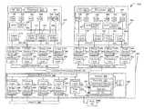
- FIG. 2is a block diagram of a first embodiment of a system 200 configured to provide improved data frame communication between blade server computers. Instead of relying upon numerous top of rack and chassis switches to forward data frames, the system 200 may include a distributed virtual bridge that allows a server computer to directly communicate with another server computer housed within a different rack or chassis.
- the server computersmay connect to one or more bridge elements that may access address data (e.g., MAC addresses) maintained at a controlling bridge.
- address datae.g., MAC addresses
- a bridge element of the distributed virtual bridgemay evaluate a forwarding cache for address data. If the address data is absent from the forwarding cache, the bridge element may send a message to a controlling bridge.
- the controlling bridgemay communicate the address data though other bridge elements to the requesting bridge element.
- the requesting bridge elementmay learn, or store, the address data within its forwarding cache.
- a distributed virtual bridge network 260may extend across server computers 206 - 225 , chassis 246 , 248 , 250 , 252 , and racks 202 , 204 to provide a multilayer hierarchy with data link layer (i.e., Layer 2) switching between the bridge elements.
- the system 200may provide a frame-based, Ethernet-like interface that facilitates lossless, point-to-point, in-order frame delivery between server computers 206 - 225 of different racks 202 , 204 or chassis 246 , 248 , 250 , 252 (i.e., east-west connectivity) without using a top of rack switch.
- the system 200further includes an end-of-rack switch 258 and input/output (I/O) server ITEs 258 , 261 that enable north-south connectivity.
- the I/O server ITEs 254 , 256may enable uplink connectivity to the external Ethernet network (or other network) for the server computers 206 - 225 housed within the racks 204 , 206 .
- An arrow 264 of FIG. 2represents direct east-west connectivity and the flow of data frames between server computers located in different racks 202 , 204 of the system 200 (e.g., without using a top of rack or chassis switch).
- An arrow 262represents direct east-west connectivity across different chassis 246 , 248 of the rack 202 .
- the system 200 of FIG. 2may thus enable direct connectivity between server computers of different racks or chassis without using a chassis or a top of rack switch.
- the direct connectivitymay facilitate faster processing with reduced contention for resources and increased data frame traffic flow.
- the system 200may further facilitate direct connectivity between server computers and at least one of Ethernet adapters and external Ethernet ports.
- the distributed nature of the system 200may further provide redundancy and fault tolerance.
- FIG. 3generally shows a computer system 300 configured to forward data frames using a distributed virtual bridge 308 .
- the computer system 300includes a first server computer 302 , a second server computer 304 , and an I/O blade device 306 that are coupled via the distributed virtual bridge 308 .
- the server computers 302 , 304 and the I/O blade device 406may be housed within separate chassis and racks.
- the distributed virtual bridge 308may be coupled to multiple adapters 310 , 312 , 314 , 316 , 318 , 320 , 322 , and 324 .
- the adapters 310 , 312 , 314 , 316 , 318 , 320 , 322 , and 324may be located within or may be coupled to the server computers 302 , 304 .
- the distributed virtual bridge 308may use multiple access points, or bridge elements 326 , 328 , 330 , and 332 - 340 to couple to the server computers 302 , 304 and the I/O blade device 306 .
- a microchip that includes the bridge elements 326 , 328 , 330 , and 332may be cabled or otherwise coupled to a port of the server computer 302 that includes the adapter 310 .
- the distributed virtual bridge 308may functionally supplant chassis switches and top of rack switches with a frame-based network fabric that functions in a similar fashion to an Ethernet network.
- One or more transport layer modules 382 , 384 , 386 , and 388 coupled to the bridge elements 326 , 328 , 330 , and 332may provide a frame-based, Ethernet-like interface to one or more integrated switch routers 342 .
- the transport layer module 382may be configured to deconstruct a transmission of data frames so that packet information may be evenly distributed across links to the local rack interconnect 390 .
- the data framesmay not be serialized upon leaving the transport layer module 382 .
- a receiving transport layer module 323may serialize the data frames to achieve reliable, in-order delivery. If data frame information is determined to be missing by the receiving transport layer module 323 , a process may be initiated by the transport layer module 323 to recover the missing data.
- the translation processmay be accomplished in hardware, which may provide a larger bandwidth and faster processing than software applications.
- the transport layer modules 382 , 384 , 386 , and 388 , the integrated switch router 342 , and a local rack interconnect network 390may combine to include an underlying lossless, point-to-point communication network (i.e., an integrated switch router network) between the server computers 302 , 304 and the I/O blade device 306 .
- the bridge elements 326 , 328 , 330 , and 332may function as data link layer (i.e., Layer 2) bridge forwarders within the distributed virtual bridge 308 .
- the bridge elements 326 , 328 , 330 , and 332may include learned (e.g., received and stored) cached address data used to forward data frames throughout the distributed virtual bridge 308 .
- the bridge element 326may query a controlling bridge 348 for the address data.
- the controlling bridge 348may include a global forwarding table 311 that includes stored address data.
- the stored address datamay be continuously updated by the bridge elements 326 , 328 , 330 , and 332 .
- a bridge element 326may send an update message to the controlling bridge 348 in response to learning an updated or new MAC address.
- a corresponding MAC address in the global forwarding table 311may be subsequently updated.
- the address data of the global forwarding table 311may be used to update the bridge elements 326 , 328 , 330 , and 332 .
- the controlling bridge 348may respond to a query from the bridge element 326 with requested address data.
- the bridge element 326may cache the received address data for future use.
- the first server computer 302may comprise a blade server computer, such as the server computer 206 shown in FIG. 2 .
- the first server computer 302may include one or more virtual machines (VMs) 350 , 352 , 354 , 356 , 358 , and 360 .
- VMsvirtual machines
- a virtual machinemay include a software implementation of a computer and may execute programs in a manner similar to a physical machine.
- FIG. 3shows an illustrative hypervisor 362 that is coupled to both the virtual machine 350 and the virtual machine 352 .
- the hypervisor 362may include platform virtualization software that allows multiple operating systems to run concurrently on the first server computer 302 .
- the hypervisor 362may include a hypervisor virtual bridge 364 that allows direct communication between the virtual machines 350 , 352 without having to traverse an external network.
- the hypervisor virtual bridge 364may register address information with the controlling bridge 348 .
- the server computer 302may include at least one processor 303 coupled to a memory 305 .
- the processor 303may represent one or more processors (e.g., microprocessors), and the memory 305 may represent random access memory (RAM) devices comprising the main storage of the server computer 302 , as well as supplemental levels of memory, e.g., cache memories, non-volatile or backup memories (e.g., programmable or flash memories), read-only memories, etc.
- the memory 305may be considered to include memory storage physically located in the server computer 302 or on another server computer 304 coupled to the server computer 302 via the distributed virtual bridge 308 .
- the server computer 302may operate under the control of an operating system (OS) 307 and may execute or otherwise rely upon various computer software applications, components, programs, objects, modules, and data structures, such as the virtual machines 350 , 352 , 354 , 356 , 358 , and 360 . Moreover, various applications, components, programs, objects, modules, etc. may also execute on one or more processors in another device coupled to the server computer 302 (e.g., in a distributed computing environment, where computing processes may be allocated to multiple server computer computers).
- OSoperating system
- the first server computer 302may include adapters 310 , 312 , 314 , and 316 , such as converged network adapters.
- a converged network adaptermay include a single root I/O virtualization (SR-IOV) adapter, such as a Peripheral Component Interconnect Express (PCIe) adapter that supports Converged Enhanced Ethernet (CEE).
- the adapters 310 , 312 , 314 , and 316may be used to implement a Fiber Channel over Ethernet (FCoE) protocol.
- FCoEFiber Channel over Ethernet
- Each adapter 310 , 312 , 314 , and 316may be coupled to one or more of the virtual machines 350 , 352 , 354 , 356 , 358 , and 360 .
- the adapters 310 , 312 , 314 , and 316may facilitate shared access of the virtual machines 350 , 352 , 354 , 356 , 358 , and 360 . While the adapters 310 , 312 , 314 , and 316 are shown in FIG. 3 as being included within the server computer 302 , adapters of another embodiment may include physically distinct devices that are separate from the server computers.
- Each adapter 310 , 312 , 314 , and 316may include a converged adapter virtual bridge 366 , 368 , 370 , and 372 .
- the converged adapter virtual bridges 366 , 368 , 370 , and 372may facilitate sharing of the adapters 310 , 312 , 314 , and 316 by coordinating access by the virtual machines 350 , 352 , 354 , 356 , 358 , and 360 .
- Each converged adapter virtual bridge 366 , 368 , 370 , and 372may recognize data flows included within its domain.
- a recognized domain addressmay be routed directly, without processing or storage outside of the domain of the particular converged adapter virtual bridge 366 , 368 , 370 , and 372 .
- Each adapter 310 , 312 , 314 , and 316may include one or more CEE transmit ports that couple to one of the bridge elements 326 , 328 , 330 , and 332 .
- the bridge elementsmay be co-located with the adapters, and the coupling between adapters and the bridge elements may not be Ethernet connections.
- the bridge elements 326 , 328 , 330 , and 332may be configured to forward data frames throughout the distributed virtual bridge 308 .
- the bridge elements 326 , 328 , 330 , and 332may thus function as access points for the distributed virtual bridge 308 by translating between Ethernet and the integrated switch router 342 .
- the bridge elements 326 , 328 , 330 , and 332may not include buffers and may support CEE at boundaries of the distributed virtual bridge 308 .
- the bridge elements 326 , 328 , 330 , and 332may include buffers.
- Each bridge element 326 , 328 , 330 , and 332 of the distributed virtual bridge 308may include a forwarding cache 374 , 376 , 378 , and 380 .
- a forwarding cache 374 , 376 , 378 , and 380may include a lookup table that comprises address data used to forward data frames that are received by the bridge elements 326 , 328 , 330 , and 332 .
- the bridge element 326may compare address data associated with a received data frame to the address data stored in the forwarding cache 374 .
- Illustrative address datamay include routing information, such as a routing key that includes bytes of the header data of the data frame.
- the routing keymay include at least one of a virtual local area network (VLAN) tag and a logical network identifier, as well as a MAC address.
- the MAC addressmay be generated and assigned by a Fiber Channel Forwarder (FCF) 313 , as set by an administrator or computing system.
- FCFFiber Channel Forwarder
- a VLAN tagmay indicate an assigned VLAN, which may be used to segregate traffic and to allow more than one uplink. There may be multiple VLANs on an uplink. Conventionally, each VLAN may use only one uplink port. That is, only one physical, uplink port at a given time may be used to forward a data frame associated with a particular VLAN. Through the use of logical networks, a VLAN may use multiple physical ports to forward traffic while maintaining traffic segregation. Link aggregation may be used to bundle several physical links to act as one uplink with higher bandwidth.
- a logical networkmay include a logically specified network portion of the distributed virtual bridge 308 . Multiple logical networks may be included within a single bridge element. As such, a logical network may provide an additional layer of traffic separation. When so configured, logical networks may allow different customers to use the same VLAN tag. The VLANs of each customer may remain segregated by virtue of the different logical networks.
- Each physical port (e.g., an adapter or Ethernet uplink) of the distributed virtual bridge 308may be associated with a single logical network. Each logical network may therefore have an uplink to the external Ethernet network. Where an uplink is an aggregated link, VLANs may be used to segregate traffic to multiple uplinks.
- a logical networkmay have distinct forwarding and traffic management resources.
- a bridge element 326may include flow control modules and queues that are assigned to a logical network. Communication between adapters associated with different logical networks may occur through an external network. No east-west traffic may be allowed between logical networks. A virtual machine may be moved to an adapter port associated with its current logical number to preserve connectivity.
- the forwarding cache 374may evaluate a VLAN tag of a routing key to forward a received data frame.
- the determined VLANmay be used to focus only on those entries of the forwarding cache 374 associated with the determined VLAN.
- the logical network identifier of the routing keymay be evaluated to further focus the address lookup operation on entries of the forwarding cache 374 that are associated with both the determined VLAN and the logical network determined from the logical network identifier.
- the forwarding caches 374 , 376 , 378 , and 380 of the distributed virtual bridge 308may have a format similar to the global forwarding table 311 of the controlling bridge 348 .
- the forwarding caches 374 , 376 , 378 , and 380may have smaller memory capacities than the global forwarding table 311 .
- the forwarding caches 374 , 376 , 378 , and 380may further be updated with address data learned from data frames that flow through the bridge elements 326 , 328 , 330 , and 332 .
- the address datamay additionally be updated with address data received from the global forwarding table 311 .
- Invalid or changed address datathat is updated within one or more of the forwarding caches 374 , 376 , 378 , and 380 of the bridge elements 326 , 328 , 330 , and 332 may be communicated to the global forwarding table 311 of the controlling bridge 348 .
- the bridge element 326may learn a new MAC address of a newly added device that is configured to receive from or send data to the distributed virtual bridge 308 .
- the bridge element 326may verify that a source MAC address included within a received data frame is allowed at a port by checking a list stored within a memory.
- the bridge element 326may send a registration message to the controlling bridge 348 to update the global forwarding table 311 with the verified MAC address.
- the bridge element 326may further store the MAC address within the forwarding cache 374 .
- the bridge element 326may identify a MAC address that is not frequently used the forwarding cache 374 . This MAC address may be removed from the forwarding cache 374 to make storage room for other MAC addresses.
- the bridge element 326may send an update message to the controlling bridge 348 to have the MAC address removed from the global forwarding table 311 .
- Address data stored within the global forwarding table 311may be communicated to one or more forwarding caches 374 , 376 , 378 , and 380 of the distributed virtual bridge 308 .
- the bridge element 326may receive a data frame that includes a destination MAC address that is not stored within the forwarding cache 374 .
- the bridge element 326may send a query to a bridge element 339 configured to access the controlling bridge 348 .
- the bridge element 339may search the global forwarding table 311 for address data associated with the destination MAC address. If found, the bridge element 339 may forward the MAC address through the distributed virtual bridge 308 to the querying bridge element 326 .
- the bridge element 326may store the MAC address as address data within the forwarding cache 374 .
- the address data included within the forwarding caches 374 , 376 , 378 , and 380 of the distributed virtual bridge 308may include both internal address information, as well as addresses that are external to the system 300 .
- Each of the bridge elements 326 , 328 , 330 , and 332may be connected to one or more transport layer modules 382 , 384 , 386 , and 388 .
- the transport layer modules 382 , 384 , 386 , and 388may include buffering used for attachment to the integrated switch router 342 .
- the transport layer modules 382 , 384 , 386 , and 388may further provide a frame-based, Ethernet-like interface to integrated switch router 342 .
- the transport layer modules 382 , 384 , 386 , and 388may each include a shared buffer used to transmit frames across the integrated switch router 342 . Additional buffers of the transport layer modules 382 , 384 , 386 , and 388 may be used to receive data frames from the integrated switch router 342 .
- the buffersmay be divided among different virtual lanes. Virtual lanes may include logically separated paths for data frame traffic flowing between a bridge element and a transport layer module. For example, there may be four virtual lanes between the bridge element 326 and the transport layer module 382 .
- the transport layer modules 382 , 384 , 386 , and 388may include logic to recover from faulty microchips and links between a source and a destination.
- the transport layer modules 382 , 384 , 386 , and 388may maintain a strict ordering of packets within the same virtual lane regardless of each data frame's path through the local rack interconnect network 390 and the computer system 300 .
- the integrated switch router 342may communicate with the transport layer modules 382 , 384 , 386 , and 388 and may facilitate routing and packet delivery to and from the local rack interconnect network 390 .
- the local rack interconnect network 390may include links to the bridge elements 326 , 328 , 330 , and 332 located within the same chassis and rack, as well as links to the bridge elements 333 - 340 in different chassis and racks.
- the local rack interconnect network 390may include point-to-point connections, or pipes, between bridge elements 326 , 328 , 330 , 332 , and 333 - 340 of the distributed virtual bridge 308 with no loss and with in-order frame delivery.
- the second server computer 304may include a server computer similar to the first server computer 302 and may be similar to the server computer 216 of FIG. 2 . As such, the second server computer 304 may be located within a different chassis and rack than the first server computer 302 . Similar to the first server computer 302 , the second server computer 304 may include a processor 399 coupled to a memory 397 and an operating system 395 . The second server computer 304 may further include virtual machines 355 , 357 , 359 , 361 , 363 , and 365 .
- a hypervisor 367may be coupled to the virtual machines 357 , 359 .
- the hypervisor 367may include a hypervisor virtual bridge 371 that allows direct communication between the virtual machines 357 , 359 .
- a hypervisor virtual bridge 373 of a hypervisor 369 coupled to the virtual machines 363 , 365may facilitate direct communication between the virtual machines 361 , 363 .
- the hypervisor virtual bridges 371 , 373may register address data with the controlling bridge 348 .
- the second server computer 304may also include one or more adapters 318 , 320 , 322 , and 324 , such as converged CEE network adapters.
- Each adapter 318 , 320 , 322 , and 324may be coupled to one or more of the virtual machines 355 , 357 , 359 , 361 , 363 , and 365 .
- the adapters 318 , 320 , 322 , and 324may each include a converged adapter virtual bridge 375 , 377 , 379 , and 381 .
- the converged adapter virtual bridges 375 , 377 , 379 , and 381may facilitate sharing of the adapters 318 , 320 , 322 , and 324 by coordinating virtual machine access.
- the adapters 318 , 320 , 322 , and 324may each couple to one or more of the bridge elements 334 , 336 , 338 , and 340 of the distributed virtual bridge 308 .
- Each adapter 318 , 320 , 322 , and 324may include one or more CEE transmit ports that couple to one of the bridge elements 334 , 336 , 338 , or 340 .
- Each bridge element 334 , 336 , 338 , and 340may include a forwarding cache 383 , 385 , 387 , and 389 that includes address data used to forward data frames that are received by the bridge elements 334 , 336 , 338 , and 340 .
- the bridge elements 334 , 336 , 338 , and 340may each be connected to one or more transport layer modules 315 , 317 , 319 , and 321 .
- the transport layer modules 315 , 317 , 319 , and 321may include buffering used for the attachment to the integrated switch router 346 .
- the transport layer modules 315 , 317 , 319 , and 321may further provide a frame-based, Ethernet-like interface to the integrated switch router 346 and may maintain packet ordering.
- a portion of the distributed virtual bridge 308 shown in FIG. 3 above the local rack interconnect network 390 as being associated with the first and second server computers 302 , 304may be referred to as a north portion.
- the bridge elements 326 , 328 , 330 , 332 , 334 , 336 , 338 , and 340may couple to the adapters 310 , 312 , 314 , 316 , 318 , 320 , 322 , and 324 .
- the I/O blade device 306may be the I/O server computer 258 of FIG. 2 . As such, the I/O blade device 306 may allow uplink connectivity to the external Ethernet 392 via an integrated switch router 342 that is coupled to the transport layer modules 323 , 325 , 327 , 329 , and 331 .
- the transport layer modules 323 , 325 , 327 , 329 , and 331may each couple to a bridge element 333 , 335 , 337 , and 339 .
- the bridge elements 333 , 335 , 337 , and 339may each include a forwarding cache 341 , 343 , 345 , and 347 .
- the I/O blade device 306may be categorized as being included within a south portion of the distributed virtual bridge 308 because the bridge elements 333 , 335 , 337 , and 339 of the I/O blade device 306 may be coupled to an uplink to the Ethernet 392 .
- the I/O blade device 306may include a memory 309 , an operating system 391 , and a processor 353 that includes the controlling bridge 348 .
- the bridge element 339may be coupled to the processor 353 via an Ethernet link connection 351 .
- the transport layer module 331may be coupled to a PCIe bus 344 that is coupled via a PCIe link connection 349 to the processor 353 and the controlling bridge 348 .
- the PCIe bus 344may also be coupled to a PCIe slot 393 .
- the controlling bridge 348may directly or indirectly communicate with, or otherwise be coupled to, the bridge elements 326 , 328 , 330 , and 332 - 340 and other controlling bridges (not shown) of the computer system 300 .
- the controlling bridge 348may include firmware executing on the processor 353 that manages the bridge elements 326 , 328 , 330 , and 332 - 340 .
- the controlling bridge 348may be configured to divide a workload between the bridge elements 326 , 328 , 330 , and 332 - 340 , as well as perform synchronization procedures and failover operations.
- the controlling bridge 348may include the Fiber Channel Forwarder 313 .
- the FCoE forwarder 313may include firmware that encapsulates and de-encapsulates fiber channel data frames (e.g., FCoE formatted data frames). FCoE may offer the capability to transport fiber channel payloads on top of an Ethernet network.
- the controlling bridge 348may additionally include the global forwarding table 311 .
- the global forwarding table 311may include address data (e.g., MAC addresses) that is registered and maintained through communication and cooperation with the bridge elements 326 , 328 , 330 , and 332 - 340 , and in some cases, the hypervisors 362 , 367 , and 369 .
- the global forwarding table 311may maintain MAC addresses that have been learned by a bridge element 326 .
- the bridge element 326may register the address with the controlling bridge 348 .
- the controlling bridge 348may update the global forwarding table 311 by adding the address to the global forwarding table 311 .
- a bridge element 326may cause the controlling bridge 348 to update the global forwarding table 311 by sending an update message to the controlling bridge 348 .
- the update messagemay cause the controlling bridge 348 to delete a MAC address that has been aged out by a bridge element 326 .
- a MAC addressmay further be deleted when the bridge element 326 has detected that the address data is no longer valid.
- a hypervisor virtual bridge 364may register MAC addresses or other address data with the controlling bridge 348 .
- the global forwarding table 311may include address data associated with addresses that are included within the system 300 , as well as addresses that are external to the system 300 .
- FIG. 3thus shows an embodiment of a system 300 that includes the distributed virtual bridge 308 configured for lossless, point-to-point, in-order data frame delivery.
- a portion of the distributed virtual bridge 308e.g., the bridge element 326 , the transport layer module 382 , and the integrated switch router 342 ) may be coupled directly to the server computer 302 .
- the system 300may support Fiber channel over Ethernet (FCoE) and may be scalable to include hundreds or more server computers with direct connectivity.
- a data framemay be forwarded directly between different racks and chassis without traversing a top of rack switch.
- FCoEFiber channel over Ethernet
- FIG. 4is an embodiment of an illustrative data frame 400 that may be forwarded by the system 300 of FIG. 3 .
- the data frame 400may include address data, such as MAC addresses (e.g., a source address 402 ) and a routing key used by the distributed virtual bridge 308 of FIG. 3 to forward the data frame 400 .
- MAC addressese.g., a source address 402
- routing keyused by the distributed virtual bridge 308 of FIG. 3 to forward the data frame 400 .
- the data frame 400may include a destination address 404 .
- the destination address 404 and the source address 402may comprise MAC addresses.
- MAC addressesare typically constructed by a Fiber Channel Forwarder, such as the Fiber Channel Forwarder 313 of FIG. 3 .
- An illustrative MAC addressmay include a combination of three-bytes of a destination identifier associated with a destination node (e.g., a MAC address of a server computer or virtual machine) with three-bytes of Fiber Channel (FC) mapping information assigned by the Fiber Channel Forwarder 313 .
- a MAC address of an embodimentmay include an Internet Protocol address.
- a logical network identifier 406may indicate a logical network associated with the data frame 400 .
- a logical networkmay be included to provide an additional layer of traffic separation.
- the logical network identifier 406may be assigned by an adapter or a bridge element that receives the data frame 400 .
- the logical network identifier 406may be included when the data frame 400 is generated. Forwarding of the data frame 400 may occur within the assigned logical network.
- a VLAN tag 408may indicate a VLAN assigned to the data frame 400 .
- the Ether Type 410 of the data frame 400may indicate a protocol of the payload 412 .
- the Ether Type 410may indicate that the protocol of the payload is FCoE or Internet Protocol.
- the Frame Check Sequence (FCS) 414may include a checksum added to the data frame 400 for error detection and correction.
- a bridge elementmay receive the data frame and look up a MAC address stored within a forwarding cache by reading the routing key 416 . Only those forwarding cache entries that are associated with the VLAN tag 408 may be searched within the forwarding cache. The logical network identifier 406 of the routing key 416 may be evaluated to further focus the address lookup operation of entries of the forwarding cache. The data frame 400 of FIG. 4 may thus be forwarded according to the logical network identifier 406 , the VLAN tag 408 , and the address data (e.g., the destination address 404 ).
- FIG. 5is an embodiment of a system 500 that depicts logical connectivity between a plurality of server computers 502 - 513 that are coupled to physical ports 514 - 522 via a distributed virtual bridge 524 .
- the connectivitymay be divided and segregated by assigning or otherwise associating VLANs 526 , 528 , 530 , 532 , 534 , 536 , 538 , 540 , 542 , and 544 and logical networks 546 and 548 to server computers 502 - 513 and ports 514 - 522 .
- Each of the server computers 502 - 513may be similar to the server computers 302 , 304 (e.g., blade server computers) shown in FIG. 3 .
- the distributed virtual bridge 524may be similar to the distributed virtual bridge 308 of FIG. 3 , and the physical ports 514 - 522 may be coupled to an Ethernet or other network, such as the Ethernet 392 of FIG. 3 .
- a first VLAN 526may be associated with the server computers 502 , 503 and the ports 514 - 517 . As such, only the server computers 502 , 503 may communicate using the first VLAN 526 over the ports 514 - 517 .
- the multiple ports 514 - 517may be used in parallel to form an aggregated link.
- a second VLAN 528 , a third VLAN 530 , a fourth VLAN 532 , and a fifth VLAN 534may share access to the port 518 .
- the second VLAN 528may be associated with the server computer 504 .
- the third VLAN 530may be associated with the server computer 505
- the fourth VLAN 532may be associated with the server computer 506 .
- the fifth VLAN 534may be associated with the server computer 507 .
- the server computer 508may be associated with six and seventh VLANs 536 .
- the VLANs 526 , 528 , 530 , 532 , 534 , and 536may be associated with a first logical network 546 .
- the server computers 502 - 508 and the ports 514 - 519may also be associated with the first logical network 546 .
- Data frames received by a bridge element of the distributed virtual bridge 524may include a logical network identifier that is used to route the data frame to the identified first logical network 546 .
- Data frames routed to the first logical network 546may be segregated from other logical networks (e.g., the second logical network 548 ).
- a VLAN tag of the data framemay identify a VLAN 526 associated with the identified logical network 546 .
- two customers using the same VLAN tag(e.g., “VLAN 1 ”) may achieve that the data frames are separately routed and segregated by using different logical network identifiers.
- the first VLAN 538 of a second logical network 548may be associated with the server computers 509 , 510 and the port 520 .
- the first VLAN 538may be associated with the same VLAN tag (e.g., “VLAN 1 ”) as the first VLAN 526 of the first logical network 546 .
- the second VLAN 540 and the third VLAN 542may share access to the port 521 .
- the second VLAN 540 of the second logical network 548may include the server computer 511 .
- the second VLAN 540 of the second logical network 548may include the same VLAN tag (e.g., “VLAN 2 ”) as the second VLAN 528 of the first logical network 546 .
- the third VLAN 542 of the second logical network 548may include the server computer 512
- the eighth VLAN 544may include the server computer 513 and the port 522 .
- FIG. 5thus shows a logical representation of segregated communications within a distributed virtual bridge 524 having VLANs 526 , 528 , 530 , 532 , 534 , and 536 and logical networks 546 , 548 .
- a data framemay be routed within the distributed virtual bridge 524 using a VLAN tag and a logical network identifier.
- the different networks 546 , 548may allow for a layer of traffic separation in addition to the VLANs 526 , 528 , 530 , 532 , 534 , and 536 .
- VLANs 528 , 540 having the same VLAN tagmay be used within the different logical networks 546 , 548 to preserve separate communication channels.
- FIG. 6is a flow diagram of an embodiment of a method of forwarding a data frame and is generally designated 600 .
- the method 600is performed by the system 300 of FIG. 3 .
- the method 600includes receiving a data frame at a distributed virtual bridge, at 602 .
- an illustrative distributed virtual bridge 308may include a first bridge element 326 coupled to a first server computer 302 .
- the distributed virtual bridge 308may further include a second bridge element 334 coupled to (e.g., in communication with) the first bridge element 326 and to a second server computer 304 .
- a controlling bridge 348 of the distributed virtual bridge 308may be coupled to the first bridge element 326 and to the second bridge element 334 .
- Address data associated with the data framemay be retrieved from a forwarding cache of the first bridge element or from a global forwarding table of the controlling bridge, at 604 .
- address datamay be retrieved from the forwarding cache 374 of the bridge element 326 or from the global forwarding table 311 of the controlling bridge 348 of FIG. 3 .
- a virtual local area network tag and a logical network identifiermay be retrieved from a data frame, at 606 .
- the bridge element 326 of FIG. 3may retrieve a local area network tag and a logical network identifier from an arriving data frame.
- the data framemay be forwarded from the first bridge element to the second bridge element of the distributed virtual bridge using the address data, the virtual local area network tag, and the logical network identifier, at 608 .
- the data framemay be forwarded from the bridge element 326 of FIG. 3 to the bridge element 334 of the distributed virtual bridge 308 using the address data, the virtual local area network tag, and the logical network identifier.
- FIG. 6thus shows a method 600 that facilitates lossless, point-to-point, in-order frame delivery of a data frame between bridge elements of a virtual distributed bridge.
- the data framemay be forwarded between different racks and chassis without traversing a top of rack switch.
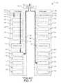
- FIG. 7is a flow diagram of an embodiment of a method of forwarding a data frame and is generally designated 700 .
- the method 700may be performed by the system 300 of FIG. 3 .
- the method 700includes associating a logical network with a virtual machine, at 702 .
- an administratormay assign a logical network identifier to a virtual machine, such as the virtual machine 350 of FIG. 3 .
- the assignmentmay result in communications sent from the virtual machine 350 being recognized and associated with the logical network identifier and corresponding logical network.
- a data framemay be received from the virtual machine at an adapter, at 704 .
- the adaptermay associate the logical network identifier with the data frame based upon the virtual machine, at 706 .
- the adapter 310may receive a data frame from the virtual machine 350 .
- the adapter 310may recognize that the data frame was received from the virtual machine 350 .
- the data framemay include a source address or other identifier in the data frame that indicates that the virtual machine 350 originated the data frame.
- the adapter 310may use the source address or other identifier in the data frame to look up or otherwise determine the logical identifier associated with the virtual machine 350 .
- the adapter 310may assign the determined logical identifier to the data frame.
- the data framemay be forwarded according to the logical network identifier, at 708 .
- the bridge element 326 of FIG. 3may forward the data frame throughout the distributed virtual bridge 308 and the system 300 using the logical network identifier.
- FIG. 7thus shows a method 700 that includes associating a logical network identifier with a data frame at an adapter.
- the associationmay occur automatically when the adapter recognizes the source of the data frame, such as a virtual machine associated with the logical network.
- the automatic associationmay allow segregation between different customers desiring to use the same VLAN tag.
- the method 700may further facilitate lossless, point-to-point communications with in-order frame delivery.
- FIG. 8is a flow diagram of another embodiment of a method of forwarding data frames and is generally designated 800 .
- the method 800is performed by the system 300 of FIG. 3 .
- the method 800includes associating a logical network with a bridge element, at 802 .
- an administratormay assign a logical network identifier to a bridge element, such as the bridge element 326 of FIG. 3 .
- the assignmentmay result in communications arriving at the bridge element 326 being associated with the logical network identifier and corresponding logical network.
- the data framemay be received at a port of the bridge element, at 804 .
- the data framemay be received at the bridge element 326 of FIG. 3 .
- the data framemay be associated with the logical identifier and corresponding logical network, at 806 .
- that data frame 400 of FIG. 4may be assigned the logical identifier 408 .
- the data framemay be forwarded according to the logical network identifier, at 808 .
- FIG. 8thus shows a method 800 that includes associating a logical network identifier with a data frame at a bridge element.
- the associationmay occur automatically when the data frame arrives at a port of the bridge element and may allow for a layer of data frame separation, in addition to that provided by VLANs.
- embodimentscan take the form of an entirely hardware embodiment, an entirely software embodiment, or an embodiment containing both hardware and software elements. Further, embodiments may take the form of a computer program product accessible from a computer-usable or computer-readable medium providing program code for use by or in connection with a computer or any instruction execution system.
- a computer-usable or computer readable mediumcan be any apparatus that can contain, store, or communicate the program for use by or in connection with the instruction execution system, apparatus, or device.
- the mediumcan be an electronic, magnetic, optical, electromagnetic, infrared, or semiconductor system (or apparatus or device).
- Examples of a computer-readable mediuminclude a semiconductor or solid state memory, magnetic tape, a removable computer diskette, a random access memory (RAM), a read-only memory (ROM), a rigid magnetic disk, and an optical disk.
- Examples of optical disksinclude compact disc-read only memory (CD-ROM), compact disc-read/write (CD-R/W) and DVD.
- a data processing system suitable for storing and/or executing program codewill include at least one processor coupled directly or indirectly to memory elements through a system bus.
- the memory elementscan include local memory employed during actual execution of the program code, bulk storage, and cache memories that provide temporary storage of at least some program code in order to reduce the number of times code must be retrieved from bulk storage during execution.
Landscapes
- Engineering & Computer Science (AREA)
- Computer Networks & Wireless Communication (AREA)
- Signal Processing (AREA)
- Data Exchanges In Wide-Area Networks (AREA)
Abstract
Description
Claims (20)
Priority Applications (1)
| Application Number | Priority Date | Filing Date | Title |
|---|---|---|---|
| US12/751,249US8594100B2 (en) | 2010-03-31 | 2010-03-31 | Data frame forwarding using a distributed virtual bridge |
Applications Claiming Priority (1)
| Application Number | Priority Date | Filing Date | Title |
|---|---|---|---|
| US12/751,249US8594100B2 (en) | 2010-03-31 | 2010-03-31 | Data frame forwarding using a distributed virtual bridge |
Publications (2)
| Publication Number | Publication Date |
|---|---|
| US20110243134A1 US20110243134A1 (en) | 2011-10-06 |
| US8594100B2true US8594100B2 (en) | 2013-11-26 |
Family
ID=44709622
Family Applications (1)
| Application Number | Title | Priority Date | Filing Date |
|---|---|---|---|
| US12/751,249Active2032-03-08US8594100B2 (en) | 2010-03-31 | 2010-03-31 | Data frame forwarding using a distributed virtual bridge |
Country Status (1)
| Country | Link |
|---|---|
| US (1) | US8594100B2 (en) |
Families Citing this family (23)
| Publication number | Priority date | Publication date | Assignee | Title |
|---|---|---|---|---|
| US8385356B2 (en)* | 2010-03-31 | 2013-02-26 | International Business Machines Corporation | Data frame forwarding using a multitiered distributed virtual bridge hierarchy |
| US8594100B2 (en) | 2010-03-31 | 2013-11-26 | International Business Machines Corporation | Data frame forwarding using a distributed virtual bridge |
| US8489763B2 (en) | 2010-04-20 | 2013-07-16 | International Business Machines Corporation | Distributed virtual bridge management |
| US8619796B2 (en) | 2010-04-22 | 2013-12-31 | International Business Machines Corporation | Forwarding data frames with a distributed fiber channel forwarder |
| US8571408B2 (en) | 2010-04-22 | 2013-10-29 | International Business Machines Corporation | Hardware accelerated data frame forwarding |
| US8369296B2 (en) | 2010-04-26 | 2013-02-05 | International Business Machines Corporation | Distributed link aggregation |
| US8644139B2 (en) | 2010-04-26 | 2014-02-04 | International Business Machines Corporation | Priority based flow control within a virtual distributed bridge environment |
| US8379642B2 (en) | 2010-04-26 | 2013-02-19 | International Business Machines Corporation | Multicasting using a multitiered distributed virtual bridge hierarchy |
| US8447909B2 (en)* | 2010-07-19 | 2013-05-21 | International Business Machines Corporation | Register access in distributed virtual bridge environment |
| WO2012090996A1 (en)* | 2010-12-28 | 2012-07-05 | 日本電気株式会社 | Information system, control device, virtual network provision method and program |
| JP5084972B1 (en)* | 2011-10-27 | 2012-11-28 | 三菱電機株式会社 | Programmable logic controller and network system |
| US8891535B2 (en) | 2012-01-18 | 2014-11-18 | International Business Machines Corporation | Managing a global forwarding table in a distributed switch |
| US8861400B2 (en) | 2012-01-18 | 2014-10-14 | International Business Machines Corporation | Requesting multicast membership information in a distributed switch in response to a miss event |
| US8917736B2 (en)* | 2012-12-19 | 2014-12-23 | International Business Machines Corporation | Unified system networking with PCIE-CEE tunneling |
| WO2014113451A1 (en)* | 2013-01-15 | 2014-07-24 | Intel Corporation | A rack assembly structure |
| US9584885B2 (en)* | 2013-05-10 | 2017-02-28 | Huawei Technologies Co., Ltd. | System and method for photonic switching |
| US10567308B1 (en)* | 2019-01-28 | 2020-02-18 | Dell Products L.P. | Virtual machine virtual fabric login system |
| GB2583962B (en) | 2019-05-16 | 2022-08-31 | Rockley Photonics Ltd | Routing protocol and distributed router |
| CN114531424B (en)* | 2020-10-31 | 2023-11-10 | 华为技术有限公司 | Service data transmission method, communication network, service receiving device and storage medium |
| CN112637135A (en)* | 2020-12-04 | 2021-04-09 | 同盾控股有限公司 | Method, device and system for host network isolation based on macvlan |
| CN115865787A (en)* | 2022-11-23 | 2023-03-28 | 厦门四信通信科技有限公司 | A new data distribution management method, device, equipment and storage medium |
| CN117714807B (en)* | 2023-07-05 | 2024-08-20 | 荣耀终端有限公司 | Playing method, device, storage medium and program product of network television service |
| CN117714375A (en)* | 2023-12-13 | 2024-03-15 | 天翼物联科技有限公司 | Method, system and medium for multiple data transmission and selective reception based on user mode |
Citations (86)
| Publication number | Priority date | Publication date | Assignee | Title |
|---|---|---|---|---|
| US5901140A (en) | 1993-10-23 | 1999-05-04 | International Business Machines Corporation | Selective congestion control mechanism for information networks |
| US20030037163A1 (en) | 2001-08-15 | 2003-02-20 | Atsushi Kitada | Method and system for enabling layer 2 transmission of IP data frame between user terminal and service provider |
| US20030236852A1 (en) | 2002-06-20 | 2003-12-25 | International Business Machines Corporation | Sharing network adapter among multiple logical partitions in a data processing system |
| US20040037279A1 (en) | 2002-08-23 | 2004-02-26 | David Zelig | Virtual private LAN service using a multicast protocol |
| US20040179476A1 (en) | 2003-03-10 | 2004-09-16 | Sung-Ha Kim | Apparatus and method for controlling a traffic switching operation based on a service class in an ethernet-based network |
| US6802068B1 (en) | 1996-10-16 | 2004-10-05 | International Business Machines Corporation | Addressless internetworking |
| US20040199698A1 (en) | 2003-04-03 | 2004-10-07 | Dell Products L.P. | Apparatus and method for refreshing a terminal display in a multiple information handling system environment |
| US6807172B1 (en)* | 1999-12-21 | 2004-10-19 | Cisco Technology, Inc. | Method and apparatus for learning and switching frames in a distributed network switch |
| US6980547B1 (en)* | 2000-10-31 | 2005-12-27 | Intel Corporation | Distributed switch/router silicon engine |
| US20060023708A1 (en) | 2004-07-30 | 2006-02-02 | Snively Robert N | Interfabric routing header for use with a backbone fabric |
| US7023857B1 (en) | 2000-09-12 | 2006-04-04 | Lucent Technologies Inc. | Method and apparatus of feedback control in a multi-stage switching system |
| US20060149886A1 (en) | 2005-01-05 | 2006-07-06 | Via Technologies, Inc. | Bus controller and bus control method for use in computer system |
| WO2006093929A2 (en) | 2005-02-28 | 2006-09-08 | Blade Network Technologies, Inc. | Blade server system with rack-switch |
| US7107360B1 (en) | 2001-07-24 | 2006-09-12 | Cisco Technology, Inc. | Network address translation in a gateway |
| US20060248158A1 (en) | 2003-05-30 | 2006-11-02 | Sam-Chul Ha | Home network system |
| US20060251067A1 (en) | 2004-10-22 | 2006-11-09 | Cisco Technology, Inc., A Corporation Of California | Fibre channel over ethernet |
| US7138733B2 (en)* | 2001-12-13 | 2006-11-21 | Hewlett-Packard Development Company, L.P. | Redundant data and power infrastructure for modular server components in a rack |
| US7167922B2 (en) | 2002-10-18 | 2007-01-23 | Nokia Corporation | Method and apparatus for providing automatic ingress filtering |
| US20070047536A1 (en) | 2005-09-01 | 2007-03-01 | Emulex Design & Manufacturing Corporation | Input/output router for storage networks |
| US20070067432A1 (en) | 2005-09-21 | 2007-03-22 | Toshiaki Tarui | Computer system and I/O bridge |
| US20070111414A1 (en) | 2001-09-28 | 2007-05-17 | Samir Chaudhry | A Vertical Replacement-Gate Silicon-On-Insulator Transistor |
| US20070147368A1 (en) | 2002-06-04 | 2007-06-28 | Fortinet, Inc. | Network packet steering via configurable association of processing resources and netmods or line interface ports |
| US20070184572A1 (en) | 2006-02-07 | 2007-08-09 | Texas Instruments, Incorporated | Semiconductive device fabricated using a raised layer to silicide the gate |
| US7281039B1 (en) | 1998-12-24 | 2007-10-09 | Redback Networks Inc. | Domain isolation through virtual network machines |
| US20070260910A1 (en) | 2006-04-04 | 2007-11-08 | Vinit Jain | Method and apparatus for propagating physical device link status to virtual devices |
| US20070266179A1 (en) | 2006-05-11 | 2007-11-15 | Emulex Communications Corporation | Intelligent network processor and method of using intelligent network processor |
| US20070268830A1 (en) | 2006-05-19 | 2007-11-22 | Cisco Technology, Inc. | Flow based flow control in an ethernet switch backplane |
| US20070299987A1 (en) | 2006-06-26 | 2007-12-27 | Ciena Corporation | Methods and systems for packet aggregation combining connection-oriented and connection-less techniques |
| US20080002579A1 (en)* | 2004-12-21 | 2008-01-03 | Fredrik Lindholm | Arrangement and a Method Relating to Flow of Packets in Communication Systems |
| US20080056300A1 (en) | 2006-09-01 | 2008-03-06 | Emulex Design & Manufacturing Corporation | Fibre channel over ethernet |
| US20080069100A1 (en)* | 2003-08-20 | 2008-03-20 | Weyman Raphael J | System and method for distributed multicast routing |
| US20080109565A1 (en) | 2006-11-02 | 2008-05-08 | Jasmin Ajanovic | PCI express enhancements and extensions |
| US20080159260A1 (en) | 2006-12-15 | 2008-07-03 | Brocade Communications Systems, Inc. | Fibre channel over ethernet frame |
| US20080159277A1 (en) | 2006-12-15 | 2008-07-03 | Brocade Communications Systems, Inc. | Ethernet over fibre channel |
| US20090037977A1 (en) | 2007-06-15 | 2009-02-05 | Nuova Systems, Inc. | Apparatus and method for applying network policy at a network device |
| US20090161692A1 (en) | 2007-12-19 | 2009-06-25 | Emulex Design & Manufacturing Corporation | High performance ethernet networking utilizing existing fibre channel fabric hba technology |
| US20090201928A1 (en) | 2008-02-13 | 2009-08-13 | Wai Chen | Methods for reliable multicasting in local peer group (LPG) based vehicle ad hoc networks |
| US20090213869A1 (en)* | 2008-02-26 | 2009-08-27 | Saravanakumar Rajendran | Blade switch |
| US20090245791A1 (en) | 2008-03-28 | 2009-10-01 | Patricia Ann Thaler | Method and System for Fibre Channel and Ethernet Interworking |
| US20090254677A1 (en) | 2008-04-08 | 2009-10-08 | Cisco Technology, Inc. | Discovery for fibre channel over ethernet devices |
| US20090265501A1 (en) | 2008-04-16 | 2009-10-22 | Hitachi, Ltd. | Computer system and method for monitoring an access path |
| US20090276526A1 (en) | 2008-05-01 | 2009-11-05 | Carlson Scott M | Access Control List Endpoint Implementation |
| US20090323518A1 (en) | 2005-07-07 | 2009-12-31 | Laurence Rose | Ring rapid spanning tree protocol |
| US20100036995A1 (en) | 2008-08-05 | 2010-02-11 | Hitachi, Ltd. | Computer system and bus assignment method |
| WO2010024993A1 (en) | 2008-08-29 | 2010-03-04 | Extreme Networks, Inc. | Improved convergence of multicast traffic |
| US20100067374A1 (en) | 2008-09-12 | 2010-03-18 | Cisco Technology, Inc., A Corporation Of California | Reducing Flooding in a Bridged Network |
| US20100085966A1 (en) | 2007-03-12 | 2010-04-08 | Allen Samuels | Systems and methods of using application and protocol specific parsing for compression |
| US20100107162A1 (en) | 2008-03-07 | 2010-04-29 | Aled Edwards | Routing across a virtual network |
| US20100128605A1 (en) | 2008-11-24 | 2010-05-27 | Emulex Design & Manufacturing Corporation | Method and system for controlling traffic over a computer network |
| US20100150174A1 (en) | 2008-12-17 | 2010-06-17 | Emulex Design & Manufacturing Corporation | Stateless Fibre Channel Sequence Acceleration for Fibre Channel Traffic Over Ethernet |
| US7751416B2 (en) | 2003-09-18 | 2010-07-06 | Cisco Technology, Inc. | Virtual network device |
| US7756027B1 (en) | 2007-06-13 | 2010-07-13 | Juniper Networks, Inc. | Automatic configuration of virtual network switches |
| US20100257263A1 (en) | 2009-04-01 | 2010-10-07 | Nicira Networks, Inc. | Method and apparatus for implementing and managing virtual switches |
| US20100257269A1 (en) | 2009-04-01 | 2010-10-07 | Vmware, Inc. | Method and System for Migrating Processes Between Virtual Machines |
| US7831759B2 (en) | 2006-02-07 | 2010-11-09 | International Business Machines Corporation | Method, apparatus, and computer program product for routing packets utilizing a unique identifier, included within a standard address, that identifies the destination host computer system |
| US7876746B1 (en) | 2006-06-21 | 2011-01-25 | Marvell International Ltd. | Remote management for network switches |
| US7889728B2 (en)* | 2007-03-26 | 2011-02-15 | Marvell Israel (Misl) Ltd. | System and method of modifying data packet tags |
| US20110055433A1 (en) | 2009-08-18 | 2011-03-03 | Kishore Karagada R | Communicating Between Host Computers and Peripheral Resources in an Input/Output (I/O) Virtualization System |
| US20110069710A1 (en) | 2009-09-22 | 2011-03-24 | Virtensys Limited | Switching Method |
| US20110085546A1 (en) | 2008-05-30 | 2011-04-14 | Telecom Italia S.P.A. | Method and devices for multicast distribution optimization |
| US20110085557A1 (en) | 2009-10-08 | 2011-04-14 | Brocade Communications Systems, Inc. | Partitioning of Switches and Fabrics into Logical Switches and Fabrics |
| US20110103391A1 (en) | 2009-10-30 | 2011-05-05 | Smooth-Stone, Inc. C/O Barry Evans | System and method for high-performance, low-power data center interconnect fabric |
| US20110153715A1 (en) | 2009-12-17 | 2011-06-23 | Microsoft Corporation | Lightweight service migration |
| US7992149B2 (en) | 2003-06-24 | 2011-08-02 | International Business Machines Corporation | Virtual machine connection to a tangible network |
| US20110243134A1 (en) | 2010-03-31 | 2011-10-06 | International Business Machines Corporation | Data Frame Forwarding Using a Distributed Virtual Bridge |
| US20110258340A1 (en) | 2010-04-20 | 2011-10-20 | International Business Machines Corporation | Distributed Virtual Bridge Management |
| US20110262134A1 (en) | 2010-04-22 | 2011-10-27 | International Business Machines Corporation | Hardware Accelerated Data Frame Forwarding |
| US20110264610A1 (en) | 2010-04-26 | 2011-10-27 | International Business Machines Corporation | Address Data Learning and Registration Within a Distributed Virtual Bridge |
| US20110261687A1 (en) | 2010-04-26 | 2011-10-27 | International Business Machines Corporation | Priority Based Flow Control Within a Virtual Distributed Bridge Environment |
| US20110261826A1 (en) | 2010-04-22 | 2011-10-27 | International Business Machines Corporation | Forwarding Data Frames With a Distributed Fiber Channel Forwarder |
| US8054832B1 (en) | 2008-12-30 | 2011-11-08 | Juniper Networks, Inc. | Methods and apparatus for routing between virtual resources based on a routing location policy |
| US8085791B1 (en) | 2006-09-08 | 2011-12-27 | Juniper Networks, Inc. | Using layer two control protocol (L2CP) for data plane MPLS within an L2 network access node |
| US20110320671A1 (en) | 2010-06-24 | 2011-12-29 | International Business Machines Corporation | Moving ownership of a device between compute elements |
| US8090805B1 (en) | 2004-02-17 | 2012-01-03 | Cisco Technology, Inc. | System and method for performing cascaded lookups to forward packets |
| US20120027014A1 (en) | 2009-03-06 | 2012-02-02 | Futurewei Technologies, Inc. | Transport Multiplexer-Mechanisms to Force Ethernet Traffic From One Domain to Be Switched in a Different (External) Domain |
| US20120036236A1 (en) | 2007-03-27 | 2012-02-09 | Amazon Technologies, Inc. | Configuring intercommunications between computing nodes |
| US8121126B1 (en) | 2006-09-08 | 2012-02-21 | Juniper Networks, Inc. | Layer two (L2) network access node having data plane MPLS |
| US8190960B1 (en) | 2007-12-13 | 2012-05-29 | Force10 Networks, Inc. | Guaranteed inter-process communication |
| US20120147743A1 (en) | 2010-12-08 | 2012-06-14 | Fujitsu Network Communications, Inc. | Dynamic connection admission control to enforce service level agreements in multicast networks |
| US20120209940A1 (en) | 2009-11-03 | 2012-08-16 | International Business Machines Corporation | Method for switching traffic between virtual machines |
| US20120236858A1 (en) | 2010-04-26 | 2012-09-20 | Armstrong William J | Multicasting using a multitiered distributed virtual bridge hierarchy |
| US8345536B1 (en) | 2009-01-29 | 2013-01-01 | Force10 Networks, Inc. | Multicast high availability enhancements for non-stop forwarding |
| US8358661B2 (en) | 2010-04-20 | 2013-01-22 | International Business Machines Corporation | Remote adapter configuration |
| US8369296B2 (en) | 2010-04-26 | 2013-02-05 | International Business Machines Corporation | Distributed link aggregation |
| US8385356B2 (en) | 2010-03-31 | 2013-02-26 | International Business Machines Corporation | Data frame forwarding using a multitiered distributed virtual bridge hierarchy |
| US20130117469A1 (en) | 2010-07-19 | 2013-05-09 | International Business Machines Corporation | Register access in distributed virtual bridge environment |
- 2010
- 2010-03-31USUS12/751,249patent/US8594100B2/enactiveActive
Patent Citations (94)
| Publication number | Priority date | Publication date | Assignee | Title |
|---|---|---|---|---|
| US5901140A (en) | 1993-10-23 | 1999-05-04 | International Business Machines Corporation | Selective congestion control mechanism for information networks |
| US6802068B1 (en) | 1996-10-16 | 2004-10-05 | International Business Machines Corporation | Addressless internetworking |
| US8271680B2 (en) | 1998-12-24 | 2012-09-18 | Ericsson Ab | Domain isolation through virtual network machines |
| US7281039B1 (en) | 1998-12-24 | 2007-10-09 | Redback Networks Inc. | Domain isolation through virtual network machines |
| US20110061094A1 (en) | 1998-12-24 | 2011-03-10 | William Salkewicz | Domain Isolation Through Virtual Network Machines |
| US6807172B1 (en)* | 1999-12-21 | 2004-10-19 | Cisco Technology, Inc. | Method and apparatus for learning and switching frames in a distributed network switch |
| US7023857B1 (en) | 2000-09-12 | 2006-04-04 | Lucent Technologies Inc. | Method and apparatus of feedback control in a multi-stage switching system |
| US6980547B1 (en)* | 2000-10-31 | 2005-12-27 | Intel Corporation | Distributed switch/router silicon engine |
| US7107360B1 (en) | 2001-07-24 | 2006-09-12 | Cisco Technology, Inc. | Network address translation in a gateway |
| US20030037163A1 (en) | 2001-08-15 | 2003-02-20 | Atsushi Kitada | Method and system for enabling layer 2 transmission of IP data frame between user terminal and service provider |
| US20070111414A1 (en) | 2001-09-28 | 2007-05-17 | Samir Chaudhry | A Vertical Replacement-Gate Silicon-On-Insulator Transistor |
| US7138733B2 (en)* | 2001-12-13 | 2006-11-21 | Hewlett-Packard Development Company, L.P. | Redundant data and power infrastructure for modular server components in a rack |
| US20070147368A1 (en) | 2002-06-04 | 2007-06-28 | Fortinet, Inc. | Network packet steering via configurable association of processing resources and netmods or line interface ports |
| US20030236852A1 (en) | 2002-06-20 | 2003-12-25 | International Business Machines Corporation | Sharing network adapter among multiple logical partitions in a data processing system |
| US20040037279A1 (en) | 2002-08-23 | 2004-02-26 | David Zelig | Virtual private LAN service using a multicast protocol |
| US7167922B2 (en) | 2002-10-18 | 2007-01-23 | Nokia Corporation | Method and apparatus for providing automatic ingress filtering |
| US20040179476A1 (en) | 2003-03-10 | 2004-09-16 | Sung-Ha Kim | Apparatus and method for controlling a traffic switching operation based on a service class in an ethernet-based network |
| US20040199698A1 (en) | 2003-04-03 | 2004-10-07 | Dell Products L.P. | Apparatus and method for refreshing a terminal display in a multiple information handling system environment |
| US20060248158A1 (en) | 2003-05-30 | 2006-11-02 | Sam-Chul Ha | Home network system |
| US7992149B2 (en) | 2003-06-24 | 2011-08-02 | International Business Machines Corporation | Virtual machine connection to a tangible network |
| US20080069100A1 (en)* | 2003-08-20 | 2008-03-20 | Weyman Raphael J | System and method for distributed multicast routing |
| US7751416B2 (en) | 2003-09-18 | 2010-07-06 | Cisco Technology, Inc. | Virtual network device |
| US8090805B1 (en) | 2004-02-17 | 2012-01-03 | Cisco Technology, Inc. | System and method for performing cascaded lookups to forward packets |
| US20060023708A1 (en) | 2004-07-30 | 2006-02-02 | Snively Robert N | Interfabric routing header for use with a backbone fabric |
| US20060251067A1 (en) | 2004-10-22 | 2006-11-09 | Cisco Technology, Inc., A Corporation Of California | Fibre channel over ethernet |
| US20080002579A1 (en)* | 2004-12-21 | 2008-01-03 | Fredrik Lindholm | Arrangement and a Method Relating to Flow of Packets in Communication Systems |
| US20060149886A1 (en) | 2005-01-05 | 2006-07-06 | Via Technologies, Inc. | Bus controller and bus control method for use in computer system |
| WO2006093929A2 (en) | 2005-02-28 | 2006-09-08 | Blade Network Technologies, Inc. | Blade server system with rack-switch |
| US8194534B2 (en) | 2005-02-28 | 2012-06-05 | International Business Machines Corporation | Blade server system with at least one rack-switch having multiple switches interconnected and configured for management and operation as a single virtual switch |
| US20080275975A1 (en) | 2005-02-28 | 2008-11-06 | Blade Network Technologies, Inc. | Blade Server System with at Least One Rack-Switch Having Multiple Switches Interconnected and Configured for Management and Operation as a Single Virtual Switch |
| US20090323518A1 (en) | 2005-07-07 | 2009-12-31 | Laurence Rose | Ring rapid spanning tree protocol |
| US20070047536A1 (en) | 2005-09-01 | 2007-03-01 | Emulex Design & Manufacturing Corporation | Input/output router for storage networks |
| US20070067432A1 (en) | 2005-09-21 | 2007-03-22 | Toshiaki Tarui | Computer system and I/O bridge |
| US20070184572A1 (en) | 2006-02-07 | 2007-08-09 | Texas Instruments, Incorporated | Semiconductive device fabricated using a raised layer to silicide the gate |
| US7831759B2 (en) | 2006-02-07 | 2010-11-09 | International Business Machines Corporation | Method, apparatus, and computer program product for routing packets utilizing a unique identifier, included within a standard address, that identifies the destination host computer system |
| US20070260910A1 (en) | 2006-04-04 | 2007-11-08 | Vinit Jain | Method and apparatus for propagating physical device link status to virtual devices |
| US20070266179A1 (en) | 2006-05-11 | 2007-11-15 | Emulex Communications Corporation | Intelligent network processor and method of using intelligent network processor |
| US20070268830A1 (en) | 2006-05-19 | 2007-11-22 | Cisco Technology, Inc. | Flow based flow control in an ethernet switch backplane |
| US7876746B1 (en) | 2006-06-21 | 2011-01-25 | Marvell International Ltd. | Remote management for network switches |
| US20070299987A1 (en) | 2006-06-26 | 2007-12-27 | Ciena Corporation | Methods and systems for packet aggregation combining connection-oriented and connection-less techniques |
| US20080056300A1 (en) | 2006-09-01 | 2008-03-06 | Emulex Design & Manufacturing Corporation | Fibre channel over ethernet |
| US8085791B1 (en) | 2006-09-08 | 2011-12-27 | Juniper Networks, Inc. | Using layer two control protocol (L2CP) for data plane MPLS within an L2 network access node |
| US8121126B1 (en) | 2006-09-08 | 2012-02-21 | Juniper Networks, Inc. | Layer two (L2) network access node having data plane MPLS |
| US20080109565A1 (en) | 2006-11-02 | 2008-05-08 | Jasmin Ajanovic | PCI express enhancements and extensions |
| US20080159277A1 (en) | 2006-12-15 | 2008-07-03 | Brocade Communications Systems, Inc. | Ethernet over fibre channel |
| US20080159260A1 (en) | 2006-12-15 | 2008-07-03 | Brocade Communications Systems, Inc. | Fibre channel over ethernet frame |
| US20100085966A1 (en) | 2007-03-12 | 2010-04-08 | Allen Samuels | Systems and methods of using application and protocol specific parsing for compression |
| US7889728B2 (en)* | 2007-03-26 | 2011-02-15 | Marvell Israel (Misl) Ltd. | System and method of modifying data packet tags |
| US20120036236A1 (en) | 2007-03-27 | 2012-02-09 | Amazon Technologies, Inc. | Configuring intercommunications between computing nodes |
| US7756027B1 (en) | 2007-06-13 | 2010-07-13 | Juniper Networks, Inc. | Automatic configuration of virtual network switches |
| US20090037977A1 (en) | 2007-06-15 | 2009-02-05 | Nuova Systems, Inc. | Apparatus and method for applying network policy at a network device |
| US8190960B1 (en) | 2007-12-13 | 2012-05-29 | Force10 Networks, Inc. | Guaranteed inter-process communication |
| US20090161692A1 (en) | 2007-12-19 | 2009-06-25 | Emulex Design & Manufacturing Corporation | High performance ethernet networking utilizing existing fibre channel fabric hba technology |
| WO2009085536A2 (en) | 2007-12-19 | 2009-07-09 | Emulex Design & Manufacturing Corporation | High performance ethernet networking utilizing existing fibre channel fabric hba |
| US20090201928A1 (en) | 2008-02-13 | 2009-08-13 | Wai Chen | Methods for reliable multicasting in local peer group (LPG) based vehicle ad hoc networks |
| US20090213869A1 (en)* | 2008-02-26 | 2009-08-27 | Saravanakumar Rajendran | Blade switch |
| US20100107162A1 (en) | 2008-03-07 | 2010-04-29 | Aled Edwards | Routing across a virtual network |
| US20090245791A1 (en) | 2008-03-28 | 2009-10-01 | Patricia Ann Thaler | Method and System for Fibre Channel and Ethernet Interworking |
| US20090252181A1 (en) | 2008-04-08 | 2009-10-08 | Cisco Technology, Inc. | Discovery for fibre channel over ethernet devices |
| US20090254677A1 (en) | 2008-04-08 | 2009-10-08 | Cisco Technology, Inc. | Discovery for fibre channel over ethernet devices |
| US20090265501A1 (en) | 2008-04-16 | 2009-10-22 | Hitachi, Ltd. | Computer system and method for monitoring an access path |
| US20090276526A1 (en) | 2008-05-01 | 2009-11-05 | Carlson Scott M | Access Control List Endpoint Implementation |
| US20110085546A1 (en) | 2008-05-30 | 2011-04-14 | Telecom Italia S.P.A. | Method and devices for multicast distribution optimization |
| US20100036995A1 (en) | 2008-08-05 | 2010-02-11 | Hitachi, Ltd. | Computer system and bus assignment method |
| WO2010024993A1 (en) | 2008-08-29 | 2010-03-04 | Extreme Networks, Inc. | Improved convergence of multicast traffic |
| US20100067374A1 (en) | 2008-09-12 | 2010-03-18 | Cisco Technology, Inc., A Corporation Of California | Reducing Flooding in a Bridged Network |
| US20100128605A1 (en) | 2008-11-24 | 2010-05-27 | Emulex Design & Manufacturing Corporation | Method and system for controlling traffic over a computer network |
| US20100150174A1 (en) | 2008-12-17 | 2010-06-17 | Emulex Design & Manufacturing Corporation | Stateless Fibre Channel Sequence Acceleration for Fibre Channel Traffic Over Ethernet |
| US8054832B1 (en) | 2008-12-30 | 2011-11-08 | Juniper Networks, Inc. | Methods and apparatus for routing between virtual resources based on a routing location policy |
| US8345536B1 (en) | 2009-01-29 | 2013-01-01 | Force10 Networks, Inc. | Multicast high availability enhancements for non-stop forwarding |
| US20120027014A1 (en) | 2009-03-06 | 2012-02-02 | Futurewei Technologies, Inc. | Transport Multiplexer-Mechanisms to Force Ethernet Traffic From One Domain to Be Switched in a Different (External) Domain |
| US20100257269A1 (en) | 2009-04-01 | 2010-10-07 | Vmware, Inc. | Method and System for Migrating Processes Between Virtual Machines |
| US20100257263A1 (en) | 2009-04-01 | 2010-10-07 | Nicira Networks, Inc. | Method and apparatus for implementing and managing virtual switches |
| US20110055433A1 (en) | 2009-08-18 | 2011-03-03 | Kishore Karagada R | Communicating Between Host Computers and Peripheral Resources in an Input/Output (I/O) Virtualization System |
| US20110069710A1 (en) | 2009-09-22 | 2011-03-24 | Virtensys Limited | Switching Method |
| US20110085557A1 (en) | 2009-10-08 | 2011-04-14 | Brocade Communications Systems, Inc. | Partitioning of Switches and Fabrics into Logical Switches and Fabrics |
| US20110103391A1 (en) | 2009-10-30 | 2011-05-05 | Smooth-Stone, Inc. C/O Barry Evans | System and method for high-performance, low-power data center interconnect fabric |
| US20120209940A1 (en) | 2009-11-03 | 2012-08-16 | International Business Machines Corporation | Method for switching traffic between virtual machines |
| US20110153715A1 (en) | 2009-12-17 | 2011-06-23 | Microsoft Corporation | Lightweight service migration |
| US20110243134A1 (en) | 2010-03-31 | 2011-10-06 | International Business Machines Corporation | Data Frame Forwarding Using a Distributed Virtual Bridge |
| US8385356B2 (en) | 2010-03-31 | 2013-02-26 | International Business Machines Corporation | Data frame forwarding using a multitiered distributed virtual bridge hierarchy |
| US20110258340A1 (en) | 2010-04-20 | 2011-10-20 | International Business Machines Corporation | Distributed Virtual Bridge Management |
| US8358661B2 (en) | 2010-04-20 | 2013-01-22 | International Business Machines Corporation | Remote adapter configuration |
| US20110262134A1 (en) | 2010-04-22 | 2011-10-27 | International Business Machines Corporation | Hardware Accelerated Data Frame Forwarding |
| US20110261826A1 (en) | 2010-04-22 | 2011-10-27 | International Business Machines Corporation | Forwarding Data Frames With a Distributed Fiber Channel Forwarder |
| US20120236858A1 (en) | 2010-04-26 | 2012-09-20 | Armstrong William J | Multicasting using a multitiered distributed virtual bridge hierarchy |
| US20110264610A1 (en) | 2010-04-26 | 2011-10-27 | International Business Machines Corporation | Address Data Learning and Registration Within a Distributed Virtual Bridge |
| US8369296B2 (en) | 2010-04-26 | 2013-02-05 | International Business Machines Corporation | Distributed link aggregation |
| US8379642B2 (en) | 2010-04-26 | 2013-02-19 | International Business Machines Corporation | Multicasting using a multitiered distributed virtual bridge hierarchy |
| US20110261687A1 (en) | 2010-04-26 | 2011-10-27 | International Business Machines Corporation | Priority Based Flow Control Within a Virtual Distributed Bridge Environment |
| US20110320671A1 (en) | 2010-06-24 | 2011-12-29 | International Business Machines Corporation | Moving ownership of a device between compute elements |
| US20130117469A1 (en) | 2010-07-19 | 2013-05-09 | International Business Machines Corporation | Register access in distributed virtual bridge environment |
| US8447909B2 (en) | 2010-07-19 | 2013-05-21 | International Business Machines Corporation | Register access in distributed virtual bridge environment |
| US20120147743A1 (en) | 2010-12-08 | 2012-06-14 | Fujitsu Network Communications, Inc. | Dynamic connection admission control to enforce service level agreements in multicast networks |
Non-Patent Citations (32)
| Title |
|---|
| Cisco Systems, "Integrating the Cisco Catalyst Blade Switch 3130 for Dell PowerEdge M1000e Blade Enclosure into the Cisco Data Center Network Architecture-Design Guide", Oct. 2007, retrieved from the Internet: http://cisco.com/en/US/prod/collateral/sw, 29 pages. |
| Hufferd, John L., "Proxy Based Shortcut", Huffered Enterprises, Oct. 7, 2009, 21 pages. |
| IBM Patent Application entitled "Data Frame Forwarding Using a Multitiered Distributed Virtual Bridge Hierarchy," filed Mar. 31, 2010 by William J. Armstrong et al. |
| U.S. Appl. No. 12/751,187; Non-Final Office Action dated May 30, 2012; 15 pages. |
| U.S. Appl. No. 12/751,187; Notice of Allowance dated Oct. 26, 2012; 7 pages. |
| U.S. Appl. No. 12/763,306; Non-Final Office Action dated Feb. 27, 2012; 20 pages. |
| U.S. Appl. No. 12/763,306; Notice of Allowance dated Aug. 1, 2012; 6 pages. |
| U.S. Appl. No. 12/763,306; Notice of Allowance dated Mar. 14, 2013; 5 pages. |
| U.S. Appl. No. 12/763,306; Notice of Allowance dated Nov. 14, 2012; 5 pages. |
| U.S. Appl. No. 12/763,323; Non-Final Rejection dated Mar. 28, 2012; 11 pages. |
| U.S. Appl. No. 12/763,323; Notice of Allowance dated Sep. 14, 2012; 7 pages. |
| U.S. Appl. No. 12/765,109; Final Office Action dated Jun. 29, 2012; 13 pages. |
| U.S. Appl. No. 12/765,109; Non-Final Office Action dated Feb. 8, 2013; 14 pages. |
| U.S. Appl. No. 12/765,109; Non-Final Office Action dated Mar. 9, 2012; 12 pages. |
| U.S. Appl. No. 12/765,128; Final Office Action dated Aug. 1, 2012; 12 pages. |
| U.S. Appl. No. 12/765,128; Non-Final Office Action dated Apr. 3, 2012; 12 pages. |
| U.S. Appl. No. 12/765,128; Notice of Allowance dated May 13, 2013; 6 pages. |
| U.S. Appl. No. 12/767,174; Non-Final Office Action dated Feb. 23, 2012; 12 pages. |
| U.S. Appl. No. 12/767,174; Notice of Allowance dated May 30, 2012; 5 pages. |
| U.S. Appl. No. 12/767,174; Notice of Allowance dated Oct. 5, 2012; 5 pages. |
| U.S. Appl. No. 12/767,481; Non-Final Office Action dated Feb. 22, 2012; 10 pages. |
| U.S. Appl. No. 12/767,481; Notice of Allowance dated Jun. 1, 2012; 5 pages. |
| U.S. Appl. No. 12/767,481; Notice of Allowance dated Oct. 11, 2012, 5 pages. |
| U.S. Appl. No. 12/767,506; Non-Final Office Action dated Jan. 18, 2013; 7 pages. |
| U.S. Appl. No. 12/767,543; Final Office Action dated May 30, 2013; 17 pages. |
| U.S. Appl. No. 12/767,543; Non-Final Office Action dated Oct. 22, 2012; 15 pages. |
| U.S. Appl. No. 12/839,099; Final Office Action dated Oct. 25, 2012; 8 pages. |
| U.S. Appl. No. 12/839,099; Non-Final Office Action dated Jul. 9, 2012; 7 pages. |
| U.S. Appl. No. 12/839,099; Notice of Allowance dated Jan. 11, 2013; 5 pages. |
| U.S. Appl. No. 13/352,952 entitled "Requesting Multicast Membership Information in a Distributed Switch in Response to a Miss Event", filed Jan. 18, 2012 by Debra L. Angst et al., 38 pages. |
| U.S. Appl. No. 13/352,973 entitled "Managing a Global Forwarding Table in a Distributed Switch", filed Jan. 18, 2012 by Debra L. Angst et al., 39 pages. |
| U.S. Appl. No. 13/485,766; Non-Final Office Action dated Dec. 13, 2012; 10 pages. |
Also Published As
| Publication number | Publication date |
|---|---|
| US20110243134A1 (en) | 2011-10-06 |
Similar Documents
| Publication | Publication Date | Title |
|---|---|---|
| US8594100B2 (en) | Data frame forwarding using a distributed virtual bridge | |
| US8385356B2 (en) | Data frame forwarding using a multitiered distributed virtual bridge hierarchy | |
| US8566257B2 (en) | Address data learning and registration within a distributed virtual bridge | |
| US8644139B2 (en) | Priority based flow control within a virtual distributed bridge environment | |
| US8369296B2 (en) | Distributed link aggregation | |
| US8594090B2 (en) | Multicasting using a multitiered distributed virtual bridge hierarchy | |
| US8358661B2 (en) | Remote adapter configuration | |
| US8489763B2 (en) | Distributed virtual bridge management | |
| US8856419B2 (en) | Register access in distributed virtual bridge environment | |
| US8619796B2 (en) | Forwarding data frames with a distributed fiber channel forwarder | |
| US12244496B2 (en) | IP-based forwarding of bridged and routed IP packets and unicast ARP | |
| US8571408B2 (en) | Hardware accelerated data frame forwarding | |
| US9838300B2 (en) | Temperature sensitive routing of data in a computer system | |
| US9215171B2 (en) | Hashing-based routing table management | |
| US20150381773A1 (en) | Dual-Homed External Network Access in a Distributed Internet Protocol (IP) Router | |
| US9219696B2 (en) | Increased efficiency of data payloads to data arrays accessed through registers in a distributed virtual bridge |
Legal Events
| Date | Code | Title | Description |
|---|---|---|---|
| AS | Assignment | Owner name:INTERNATIONAL BUSINESS MACHINES CORPORATION, NEW Y Free format text:ASSIGNMENT OF ASSIGNORS INTEREST;ASSIGNORS:ARMSTRONG, WILLIAM J.;BASSO, CLAUDE;ENGEBRETSEN, DAVID R.;AND OTHERS;SIGNING DATES FROM 20100303 TO 20100402;REEL/FRAME:024180/0822 | |
| STCF | Information on status: patent grant | Free format text:PATENTED CASE | |
| AS | Assignment | Owner name:ARUBA NETWORKS, INC., CALIFORNIA Free format text:ASSIGNMENT OF ASSIGNORS INTEREST;ASSIGNOR:INTERNATIONAL BUSINESS MACHINES CORPORATION;REEL/FRAME:033249/0051 Effective date:20140630 | |
| AS | Assignment | Owner name:HEWLETT-PACKARD DEVELOPMENT COMPANY, L.P., TEXAS Free format text:ASSIGNMENT OF ASSIGNORS INTEREST;ASSIGNOR:ARUBA NETWORKS, INC.;REEL/FRAME:035814/0518 Effective date:20150529 | |
| AS | Assignment | Owner name:ARUBA NETWORKS, INC., CALIFORNIA Free format text:ASSIGNMENT OF ASSIGNORS INTEREST;ASSIGNOR:HEWLETT-PACKARD DEVELOPMENT COMPANY, L.P.;REEL/FRAME:036379/0274 Effective date:20150807 | |
| FPAY | Fee payment | Year of fee payment:4 | |
| AS | Assignment | Owner name:HEWLETT PACKARD ENTERPRISE DEVELOPMENT LP, TEXAS Free format text:ASSIGNMENT OF ASSIGNORS INTEREST;ASSIGNOR:ARUBA NETWORKS, INC.;REEL/FRAME:045921/0055 Effective date:20171115 | |
| MAFP | Maintenance fee payment | Free format text:PAYMENT OF MAINTENANCE FEE, 8TH YEAR, LARGE ENTITY (ORIGINAL EVENT CODE: M1552); ENTITY STATUS OF PATENT OWNER: LARGE ENTITY Year of fee payment:8 | |
| MAFP | Maintenance fee payment | Free format text:PAYMENT OF MAINTENANCE FEE, 12TH YEAR, LARGE ENTITY (ORIGINAL EVENT CODE: M1553); ENTITY STATUS OF PATENT OWNER: LARGE ENTITY Year of fee payment:12 |