US8593982B1 - Method and system for optimizing a performance indicator log mask - Google Patents
Method and system for optimizing a performance indicator log maskDownload PDFInfo
- Publication number
- US8593982B1 US8593982B1US12/938,210US93821010AUS8593982B1US 8593982 B1US8593982 B1US 8593982B1US 93821010 AUS93821010 AUS 93821010AUS 8593982 B1US8593982 B1US 8593982B1
- Authority
- US
- United States
- Prior art keywords
- log
- performance indicator
- log mask
- communication system
- mask
- Prior art date
- Legal status (The legal status is an assumption and is not a legal conclusion. Google has not performed a legal analysis and makes no representation as to the accuracy of the status listed.)
- Expired - Fee Related, expires
Links
- 238000000034methodMethods0.000titleclaimsabstractdescription27
- 238000004891communicationMethods0.000claimsabstractdescription99
- 238000012545processingMethods0.000claimsabstractdescription51
- 238000012360testing methodMethods0.000description10
- 239000002609mediumSubstances0.000description5
- 239000006163transport mediaSubstances0.000description5
- 239000011521glassSubstances0.000description3
- 239000000463materialSubstances0.000description3
- 239000002184metalSubstances0.000description3
- 230000001960triggered effectEffects0.000description3
- 239000003570airSubstances0.000description2
- 238000002405diagnostic procedureMethods0.000description2
- 238000010586diagramMethods0.000description2
- 230000005540biological transmissionEffects0.000description1
- 230000001413cellular effectEffects0.000description1
- 238000013500data storageMethods0.000description1
- 238000011156evaluationMethods0.000description1
- 239000000835fiberSubstances0.000description1
- 230000006870functionEffects0.000description1
- 230000007774longtermEffects0.000description1
- 238000010295mobile communicationMethods0.000description1
- 230000003287optical effectEffects0.000description1
- 239000000523sampleSubstances0.000description1
Images


Classifications
- H—ELECTRICITY
- H04—ELECTRIC COMMUNICATION TECHNIQUE
- H04L—TRANSMISSION OF DIGITAL INFORMATION, e.g. TELEGRAPHIC COMMUNICATION
- H04L1/00—Arrangements for detecting or preventing errors in the information received
- H—ELECTRICITY
- H04—ELECTRIC COMMUNICATION TECHNIQUE
- H04L—TRANSMISSION OF DIGITAL INFORMATION, e.g. TELEGRAPHIC COMMUNICATION
- H04L1/00—Arrangements for detecting or preventing errors in the information received
- H04L1/20—Arrangements for detecting or preventing errors in the information received using signal quality detector
- H—ELECTRICITY
- H04—ELECTRIC COMMUNICATION TECHNIQUE
- H04L—TRANSMISSION OF DIGITAL INFORMATION, e.g. TELEGRAPHIC COMMUNICATION
- H04L1/00—Arrangements for detecting or preventing errors in the information received
- H04L1/24—Testing correct operation
- H—ELECTRICITY
- H04—ELECTRIC COMMUNICATION TECHNIQUE
- H04L—TRANSMISSION OF DIGITAL INFORMATION, e.g. TELEGRAPHIC COMMUNICATION
- H04L43/00—Arrangements for monitoring or testing data switching networks
- H04L43/50—Testing arrangements
- H—ELECTRICITY
- H04—ELECTRIC COMMUNICATION TECHNIQUE
- H04W—WIRELESS COMMUNICATION NETWORKS
- H04W24/00—Supervisory, monitoring or testing arrangements
Definitions
- a wireless communication systemmay provide communication between wireless devices, and/or between wireless and wired devices.
- diagnostic monitorsare available to capture information relevant to the performance of communication systems, configuration of such systems is complex, and improper configuration may lead to capturing too much or not enough information to efficiently and effectively evaluate the communication system.
- a method to generate a communication system performance indicator log maskincludes receiving, by a processing unit, a request for a performance indicator log mask associated with a performance indicator of a communication system, retrieving, by the processing unit, a plurality of log mask values associated with the performance indicator from a storage unit, and combining, by the processing unit, the plurality of log mask values to generate the performance indicator log mask.
- the systemincludes a processing unit, a storage unit coupled to the processing unit, a user interface coupled to the processing unit configured to receive user input and provide user output, and a communication system interface coupled to the processing unit configured to monitor a performance of the communication system.
- the processing unit of the systemmay be configured to receive a request for a log including data associated with a performance indicator of a plurality of performance indicators of the communication system, determine a performance indicator log mask based on the performance indicator, and collect the log comprising data associated with the performance indicator based on the performance indicator log mask.
- FIG. 1includes a schematic diagram of an exemplary embodiment of the present teachings.
- FIG. 2includes a flowchart illustrating a process of an exemplary embodiment of the present teachings.
- FIG. 3includes a flowchart illustrating a process of an exemplary embodiment of the present teachings.
- FIG. 4includes a schematic diagram of an exemplary embodiment of the present teachings.
- FIG. 5includes a flowchart illustrating a process of an exemplary embodiment of the present teachings.
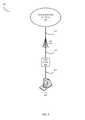
- FIG. 1illustrates a communication system 100 of an exemplary embodiment.
- Communication system 100includes a communication network 160 and a diagnostic system 110 coupled to communication network 160 through communication link 170 .
- diagnostic system 110receives a request for a performance indicator log mask associated with a performance indicator of communication network 160 .
- diagnostic system 110retrieves a plurality of log mask values associated with the performance indicator from an internal storage unit 130 and combines the plurality of log mask values to generate the requested performance indicator log mask.
- Diagnostic system 110may analyze the performance of the communication network 160 based on the performance indicator log mask, or may provide the performance indicator log mask to a user or to another device for further processing.
- Communication network 160may support one or more communication protocols, such as Code Division Multiple Access (CDMA), Evolution Data Only (EVDO), Worldwide Interoperability for Microwave Access (WiMAX), Global System for Mobile Communication (GSM), Long Term Evolution (LTE), Wireless Fidelity (WIFI), High Speed Packet Access (HSPA), or some other communication protocol.
- Communication link 170may be a wireless link which may use the air or space as its transport media and may use various protocols for communicating data, such as iDEN, CDMA, EVDO, WiMAX, GSM, LTE, WIFI, HSPA, or some other communication protocol.
- Communication link 170may also be a wired link which may use metal, glass, or some other material as the transport media and may use various protocols for communicating data, such as Internet Protocol (IP), Ethernet, or some other communication format. Communication link 170 may also be a combination of wireless and wired links.
- IPInternet Protocol
- Communication link 170may also be a combination of wireless and wired links.
- Diagnostic system 110includes processing unit 120 , user interface 140 , communication interface 150 , and storage unit 130 .
- Processing unit 120may include one or more processors and other circuitry that executes software retrieved from storage unit 130 or from an external storage unit (not shown). When executed by processing unit 120 , the software directs processing unit 120 to operate diagnostic system 110 as described herein.
- Processing unit 120may be mounted on a circuit board which may further hold storage unit 130 , communication interface 150 , user interface 140 , or portions thereof.
- Communication interface 150may include communication circuitry to interface wirelessly or in wired manner with communication network 160 .
- Communication circuitrymay include an amplifier, filter, RF modulator, signal processing circuitry and/or any other component which may allow the communication interface to communicate with the communications network via a wireless link, a fiber optic cable, a coax cable, or any other communication format.
- Communication interface 160may also include internal processing and storage circuitry, software, or some other communication device (not shown).
- User interface 140may include user input/output elements such as keyboard, keypad, display, touch-screen display, or a combination thereof. User interface 140 may also include user data input/output elements such as USB port, smart card reader, CD drive, infra red port, or a combination thereof.
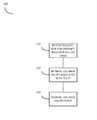
- FIG. 2illustrates a process 200 according to an exemplary embodiment for operating diagnostic system 110 .
- Processing unit 120receives a request for a key performance indicator (KPI) log mask ( 210 ).
- Processing unit 120communicates with storage unit 130 to retrieve a plurality of log mask values associated with the KPI of the request ( 220 ).
- Processing unit 120combines the plurality of log mask values to yield the requested KPI log mask value ( 230 ).
- KPIkey performance indicator
- the request for the KPI log maskmay be received by diagnostic system 110 from a user through user interface 140 , from communication network 160 through communication interface 150 , or may be generated by an internal process of the diagnostic system 110 .
- one or more log mask values of the plurality of log mask valuesmay be retrieved from sources other than storage unit 130 , such as an external storage (not shown) or another communication network (not shown).
- the resulting KPI log mask valuemay be used by the diagnostic system for further processing, may be provided to the user through user interface 140 , or may be provided to another user or device through communication interface 130 .
- FIG. 3illustrates a process 300 according to another exemplary embodiment for operating diagnostic system 110 .
- Processing unit 120receives a request for a key performance indicator (KPI) log mask ( 310 ).
- Processing unit 120communicates with storage unit 130 to retrieve a plurality of log codes associated with the KPI of the request ( 320 ).
- Processing unit 120communicates with storage unit 130 to further retrieve a plurality of log mask values associated with the plurality of log codes ( 330 ).
- Processing unit 120further communicates with storage unit 130 to also retrieve a user-defined log mask associated with the request ( 340 ).
- Processing unit 120combines the plurality of log mask values to yield the requested KPI log mask value.
- the log mask valuesare combined by performing, for example, a bit-wise ‘OR’ operation on the retrieved log masks ( 350 ).
- a user of the present embodimentmay request diagnostic system 110 a KPI, such as 1xRTT access attempts.
- the processing unit 120may retrieve from storage unit 130 a list of log codes associated with the KPI, such as access channel messages (log mask 0x02) and access probe information (log mask 0x08).
- the processing unit 120retrieves from storage unit 130 log masks associated with the log codes above and performs a bit-wise ‘OR’ operation to yield the desired KPI log mask. For the above log codes the resulting log mask is 0x0A (i.e., bit-wise ‘OR’ of 0x02 and 0x08).
- the user-defined log maskallows the user to limit or expand the amount of log messages that would be provided by that combination of log codes retrieved from storage unit 130 .
- a usermay not want to log a particular type of message triggered by a log mask of 0x0A, even though one or more of the retrieved log codes are associated with log masks which select the particular type of message.
- the usermay provide the log mask value of 0x02 which, when “XORed” with the retrieved log mask, would “zero” the bit at position 1 of the log mask (i.e., 0x02).
- a log recorded based on the resulting log maskwould not include messages triggered by a log mask of 0x02.
- the user-defined log maskmay be used to add types of log messages by configuring the diagnostic system to perform an “OR” operation when combining the user-defined log mask with the other “ORed” log masks. For example, if a user wishes to log a type of message triggered by a log mask of 0x0A, the user may provide the log mask value of 0x0A as the user-defined log mask and may instruct the diagnostic system to bit-wise “OR” the user-defined log mask to include messages. The operation would “one” the bits at positions 1 and 3 of the resulting log mask (i.e., 0x0A).
- the request for the KPI log maskmay be received from the user through user interface 140 , from communication network 160 through the communication interface 150 , or may be generated by an internal process of the diagnostic system 110 .
- one or more log mask values of the plurality of log mask valuesmay be retrieved from sources other than storage unit 130 , such as an external storage (not shown) or another communication network (not shown).
- the resulting KPI log mask valuemay be used by the diagnostic system for further processing, may be provided to the user through user interface 140 , or may be provided to another user or device through communication interface 130 .
- FIG. 4illustrates a communication system 400 of an exemplary embodiment.
- Communication system 400includes a wireless communication network 410 , an access node 420 , a test device 430 , and a personal computer 440 .
- Wireless communication network 410may support one or more communication protocols, such as CDMA, EVDO, WiMAX, GSM, LTE, WIFI, HSPA, or some other wireless communication protocol.
- Access node 420communicates with wireless communication network 410 over communication link 415 .
- Communication link 415may use metal, glass, air, space, or some other material as the transport media and may use various communication protocols, such as Internet Protocol (IP), Ethernet, or some other communication format—including combinations thereof.
- IPInternet Protocol
- Communication link 415could be a direct link or may include intermediate networks, systems, or devices.
- Access node 420may include access node radios and control equipment contained in a bade transceiver station (BTS), or cell site. However, an access node according to the present embodiment is not so limited and may be configured differently. Access node 420 may be used to provide a link between the carrier network 110 and various wireless devices, such as test device 430 , and may further provide connectively between wireless devices and other networks (not shown). Examples of external networks may be the Internet, a wide area network (WAN), a local area network (LAN), an intranet, another wireless communication network, or other type of packet-switch network.
- WANwide area network
- LANlocal area network
- intranetanother wireless communication network, or other type of packet-switch network.
- Test device 430is a wireless device of the type served by communication network 410 through access node 420 .
- Test device 430communicates with access node 420 over wireless link 425 , which may use the air or space as its transport media and may use various wireless communication protocols, such as iDEN, CDMA, EVDO, WiMAX, GSM, LTE, WIFI, HSPA, or some other wireless communication protocol.
- Test device 430may include any electronic device that may be used for voice and/or data communication over communication network 410 . Examples of test device 430 include, but are not limited to, cellular phones, personal digital assistants (PDAs), handheld devices, wireless modems, laptop computers, and personal computers.
- PDAspersonal digital assistants
- PC 440is a general purpose computer which may be configured to perform some or all functions of a diagnostic system described herein.
- General purpose computersare known in the art and generally include a user interface (e.g., monitor/display and keyboard), memory (e.g., RAM/ROM and hard disk drive), processing unit (e.g., one or more microprocessors), communication ports (e.g., USB), etc. . . . .
- a user interfacee.g., monitor/display and keyboard
- memorye.g., RAM/ROM and hard disk drive
- processing unite.g., one or more microprocessors
- communication portse.g., USB
- Communication link 435may use metal, glass, air, space, or some other material as the transport media and may use various communication protocols, such as Internet Protocol (IP), Ethernet, WIFI, Universal Serial Bus (USB), or some other communication format—including combinations thereof.
- IPInternet Protocol
- EthernetEthernet
- WIFIWireless Fidelity
- USBUniversal Serial Bus
- Communication link 435could be a direct link or may include intermediate networks, systems, or devices.
- FIG. 5illustrates a process 500 according to an exemplary embodiment for performing diagnostic tests using communication system 400 .
- PC 440is configured to execute software stored in its memory to perform diagnostic tests as described herein.
- a userenters a request for a key performance indicator (KPI) through PC 440 's user interface ( 510 ).
- PC 440 's processing unitreceives the request from the user interface ( 515 ) and communicates with memory to retrieve a plurality of log codes associated with the requested KPI ( 520 ).
- PC 440 's processing unitcommunicates with the memory to further retrieve a plurality of log mask values associated with the plurality of log codes ( 525 ).
- PC 440 's processing unitfurther communicates with memory to retrieve a user-defined log mask associated with the request ( 530 ).
- the user-defined log maskmay have been entered through the PC 440 's user interface and submitted with the request or may have been previously entered and stored in memory.
- the PC 440 's processing unitcombines the plurality of log mask values to yield the requested KPI log mask value.
- the log mask valuesare combined by performing a bit-wise ‘OR’ operation on the retrieved log masks ( 535 ).
- PC 440communicates with test device 430 and configures test device 430 to monitor communication network 410 and transmit communication network information to PC 440 ( 540 ).
- the test device 430may be configured to filter the information based on the KPI log mask (i.e., only log entries based on the KPI log mask), or may be configured to transmit all information to PC 440 and PC 440 filters the information based on the KPI log mask.
- PC 440records the filtered information in a log file ( 545 ) and may further process the recorded information to provide to the user a KPI value ( 550 ).
- the exemplary embodiments described hereincan be embodied as computer-readable codes on a tangible computer-readable recording medium.
- the tangible computer-readable recording mediumis any tangible storage device that can store data which can thereafter be read by a computer system. Examples of tangible computer-readable recording medium include, but are not limited to, read-only memory (ROM), random-access memory (RAM), CD-ROMs, magnetic tapes, floppy disks, and optical data storage devices.
- ROMread-only memory
- RAMrandom-access memory
- the exemplary embodiments described hereincan also be embodied as computer-readable codes embedded in communication signals transmitted through a transitory medium.
- the communication signalsmay include, for example, signals which modulate carrier waves transmitted through wired or wireless transmission paths.
Landscapes
- Engineering & Computer Science (AREA)
- Computer Networks & Wireless Communication (AREA)
- Signal Processing (AREA)
- Quality & Reliability (AREA)
- Debugging And Monitoring (AREA)
Abstract
Description
Claims (20)
Priority Applications (1)
| Application Number | Priority Date | Filing Date | Title |
|---|---|---|---|
| US12/938,210US8593982B1 (en) | 2010-11-02 | 2010-11-02 | Method and system for optimizing a performance indicator log mask |
Applications Claiming Priority (1)
| Application Number | Priority Date | Filing Date | Title |
|---|---|---|---|
| US12/938,210US8593982B1 (en) | 2010-11-02 | 2010-11-02 | Method and system for optimizing a performance indicator log mask |
Publications (1)
| Publication Number | Publication Date |
|---|---|
| US8593982B1true US8593982B1 (en) | 2013-11-26 |
Family
ID=49596687
Family Applications (1)
| Application Number | Title | Priority Date | Filing Date |
|---|---|---|---|
| US12/938,210Expired - Fee RelatedUS8593982B1 (en) | 2010-11-02 | 2010-11-02 | Method and system for optimizing a performance indicator log mask |
Country Status (1)
| Country | Link |
|---|---|
| US (1) | US8593982B1 (en) |
Cited By (1)
| Publication number | Priority date | Publication date | Assignee | Title |
|---|---|---|---|---|
| US9521052B1 (en)* | 2013-12-20 | 2016-12-13 | Vce Company, Llc | Methods, systems, and computer readable mediums for utilizing application programming interfaces for accessing key performance indicator information |
Citations (19)
| Publication number | Priority date | Publication date | Assignee | Title |
|---|---|---|---|---|
| US20030041046A1 (en) | 2001-07-28 | 2003-02-27 | Allison Michael S. | Method for extracting, filtering and separating events from system firmware and software |
| US20080004035A1 (en)* | 2004-01-27 | 2008-01-03 | Atkins Jeffrey B | Mobile Communications Network Monitoring Systems |
| US7349360B2 (en)* | 2003-05-19 | 2008-03-25 | Gaton Corporation | Ad-hoc network and method of routing communications in a communication network |
| US20080081632A1 (en) | 2006-09-29 | 2008-04-03 | Symbol Technologies, Inc. | Methods and apparatus for defining, storing, and identifying key performance indicators associated with an RF network |
| US7369511B2 (en)* | 2004-01-09 | 2008-05-06 | Kabushiki Kaisha Toshiba | Communication method, communication apparatus, and communication system |
| US7502350B2 (en)* | 2002-01-16 | 2009-03-10 | Sony Corporation | Communication apparatus, method and programs |
| US20090111382A1 (en) | 2007-10-26 | 2009-04-30 | Motorola, Inc. | Methods for scheduling collection of key performance indicators from elements in a communications network |
| US20090135731A1 (en)* | 2007-11-19 | 2009-05-28 | Qualcomm Incorporated | Diagnostic monitoring by a wireless device |
| US20090135817A1 (en)* | 2007-08-24 | 2009-05-28 | Assa Abloy Ab | Method for computing the entropic value of a dynamical memory system |
| US7593347B2 (en)* | 2003-12-29 | 2009-09-22 | Intel Corporation | Method and apparatus to exchange channel information |
| US7593356B1 (en)* | 2002-06-25 | 2009-09-22 | Cisco Systems, Inc. | Method and system for dynamically assigning channels across multiple access elements in a wireless LAN |
| US7613210B2 (en)* | 2006-03-26 | 2009-11-03 | Tanita Corporation | Measuring time management system, data transmitter-receiver and measuring time management method |
| US7630323B2 (en)* | 2004-03-11 | 2009-12-08 | Symbol Technologies, Inc. | Self-configuring wireless personal area network |
| US20090323542A1 (en)* | 2007-09-06 | 2009-12-31 | Tatsushi Aiba | Communication apparatus and communication method |
| US7804842B2 (en)* | 2003-09-17 | 2010-09-28 | Panasonic Corporation | Carrier sense multiple access method and wireless terminal apparatus |
| US20110026429A1 (en)* | 2008-04-11 | 2011-02-03 | Telefonaktiebolaget Lm Ericsson (Publ) | Network Coded Data Communication |
| US7940686B2 (en)* | 2005-02-09 | 2011-05-10 | Microsoft Corporation | Network performance tuner |
| US20110158110A1 (en)* | 2009-12-24 | 2011-06-30 | Robert Stacey | Method and system for multiband rate scaling |
| US20120057491A1 (en)* | 2009-04-27 | 2012-03-08 | Esa Tapani Tiirola | Method of Scheduling Transmissions in a Communication System |
- 2010
- 2010-11-02USUS12/938,210patent/US8593982B1/ennot_activeExpired - Fee Related
Patent Citations (20)
| Publication number | Priority date | Publication date | Assignee | Title |
|---|---|---|---|---|
| US20030041046A1 (en) | 2001-07-28 | 2003-02-27 | Allison Michael S. | Method for extracting, filtering and separating events from system firmware and software |
| US7502350B2 (en)* | 2002-01-16 | 2009-03-10 | Sony Corporation | Communication apparatus, method and programs |
| US7593356B1 (en)* | 2002-06-25 | 2009-09-22 | Cisco Systems, Inc. | Method and system for dynamically assigning channels across multiple access elements in a wireless LAN |
| US7349360B2 (en)* | 2003-05-19 | 2008-03-25 | Gaton Corporation | Ad-hoc network and method of routing communications in a communication network |
| US7804842B2 (en)* | 2003-09-17 | 2010-09-28 | Panasonic Corporation | Carrier sense multiple access method and wireless terminal apparatus |
| US7593347B2 (en)* | 2003-12-29 | 2009-09-22 | Intel Corporation | Method and apparatus to exchange channel information |
| US7369511B2 (en)* | 2004-01-09 | 2008-05-06 | Kabushiki Kaisha Toshiba | Communication method, communication apparatus, and communication system |
| US7830812B2 (en)* | 2004-01-27 | 2010-11-09 | Actix Limited | Monitoring system for a mobile communication network for traffic analysis using a hierarchial approach |
| US20080004035A1 (en)* | 2004-01-27 | 2008-01-03 | Atkins Jeffrey B | Mobile Communications Network Monitoring Systems |
| US7630323B2 (en)* | 2004-03-11 | 2009-12-08 | Symbol Technologies, Inc. | Self-configuring wireless personal area network |
| US7940686B2 (en)* | 2005-02-09 | 2011-05-10 | Microsoft Corporation | Network performance tuner |
| US7613210B2 (en)* | 2006-03-26 | 2009-11-03 | Tanita Corporation | Measuring time management system, data transmitter-receiver and measuring time management method |
| US20080081632A1 (en) | 2006-09-29 | 2008-04-03 | Symbol Technologies, Inc. | Methods and apparatus for defining, storing, and identifying key performance indicators associated with an RF network |
| US20090135817A1 (en)* | 2007-08-24 | 2009-05-28 | Assa Abloy Ab | Method for computing the entropic value of a dynamical memory system |
| US20090323542A1 (en)* | 2007-09-06 | 2009-12-31 | Tatsushi Aiba | Communication apparatus and communication method |
| US20090111382A1 (en) | 2007-10-26 | 2009-04-30 | Motorola, Inc. | Methods for scheduling collection of key performance indicators from elements in a communications network |
| US20090135731A1 (en)* | 2007-11-19 | 2009-05-28 | Qualcomm Incorporated | Diagnostic monitoring by a wireless device |
| US20110026429A1 (en)* | 2008-04-11 | 2011-02-03 | Telefonaktiebolaget Lm Ericsson (Publ) | Network Coded Data Communication |
| US20120057491A1 (en)* | 2009-04-27 | 2012-03-08 | Esa Tapani Tiirola | Method of Scheduling Transmissions in a Communication System |
| US20110158110A1 (en)* | 2009-12-24 | 2011-06-30 | Robert Stacey | Method and system for multiband rate scaling |
Cited By (1)
| Publication number | Priority date | Publication date | Assignee | Title |
|---|---|---|---|---|
| US9521052B1 (en)* | 2013-12-20 | 2016-12-13 | Vce Company, Llc | Methods, systems, and computer readable mediums for utilizing application programming interfaces for accessing key performance indicator information |
Similar Documents
| Publication | Publication Date | Title |
|---|---|---|
| EP4203542B1 (en) | Data transmission method and apparatus | |
| US11271823B2 (en) | Techniques for providing visualization and analysis of performance data | |
| CN105493514B (en) | Adaptive monitoring to cellular network | |
| US20190253329A1 (en) | Techniques for providing visualization and analysis of performance data | |
| US11228929B2 (en) | Selective user plane monitoring multiple monitoring probes when a serving gateway has multiple IP addresses | |
| CN105052076B (en) | A cloud computing-based network element management system and network element management method | |
| US10231143B2 (en) | Method and apparatus for use in MDT data collection | |
| KR20200004338A (en) | Method, terminal and network apparatus for determining transmission parameter of uplink signal | |
| US11044609B2 (en) | Method and device for integrity protection | |
| WO2018082397A1 (en) | Method and device for determining time domain resources for reference signal mapping | |
| US7346477B2 (en) | Testing a station's response to a reduction in wireless signal strength | |
| CN110999419B (en) | Antenna switching method and device | |
| EP3462676B1 (en) | Selective user plane monitoring using a single network monitoring probe | |
| CN104348655A (en) | Method and device for determining degree of safety and health of system | |
| WO2021013321A1 (en) | Apparatus, method, and computer program | |
| US20160065444A1 (en) | Anomaly detection based on combinations of cause value, message type, response time (gtp-c) | |
| CN103188709B (en) | A kind of method of testing of Intermodulation Interference, Apparatus and system | |
| US8593982B1 (en) | Method and system for optimizing a performance indicator log mask | |
| WO2019036851A1 (en) | Channel state information measurement and feedback method and related product | |
| CN111757344A (en) | Wireless network control optimization method and system | |
| US7599304B2 (en) | Testing a station's response to non-compliant wireless communication | |
| KR20200125607A (en) | Transmission method of downlink control information, terminal device and network device | |
| US20070201414A1 (en) | Testing a station's response to wireless communication in different modes | |
| CN110890950A (en) | Signal processing method, access network equipment and terminal equipment | |
| CN104040951A (en) | Method and apparatus for transmitting alarm-related information |
Legal Events
| Date | Code | Title | Description |
|---|---|---|---|
| AS | Assignment | Owner name:SPRINT SPECTRUM LP, KANSAS Free format text:ASSIGNMENT OF ASSIGNORS INTEREST;ASSIGNORS:WURTENBERGER, ANDREW M.;HYDE, CALEB S.;REEL/FRAME:025393/0188 Effective date:20101102 | |
| AS | Assignment | Owner name:DEUTSCHE BANK TRUST COMPANY AMERICAS, NEW YORK Free format text:GRANT OF FIRST PRIORITY AND JUNIOR PRIORITY SECURITY INTEREST IN PATENT RIGHTS;ASSIGNOR:SPRINT SPECTRUM L.P.;REEL/FRAME:041937/0632 Effective date:20170203 | |
| REMI | Maintenance fee reminder mailed | ||
| LAPS | Lapse for failure to pay maintenance fees | Free format text:PATENT EXPIRED FOR FAILURE TO PAY MAINTENANCE FEES (ORIGINAL EVENT CODE: EXP.) | |
| STCH | Information on status: patent discontinuation | Free format text:PATENT EXPIRED DUE TO NONPAYMENT OF MAINTENANCE FEES UNDER 37 CFR 1.362 | |
| FP | Lapsed due to failure to pay maintenance fee | Effective date:20171126 | |
| AS | Assignment | Owner name:SPRINT SPECTRUM L.P., KANSAS Free format text:TERMINATION AND RELEASE OF FIRST PRIORITY AND JUNIOR PRIORITY SECURITY INTEREST IN PATENT RIGHTS;ASSIGNOR:DEUTSCHE BANK TRUST COMPANY AMERICAS;REEL/FRAME:052313/0299 Effective date:20200401 |