US8593914B2 - Method and system for optically coupling a laser with a transducer in an energy assisted magnetic recording disk drive - Google Patents
Method and system for optically coupling a laser with a transducer in an energy assisted magnetic recording disk driveDownload PDFInfo
- Publication number
- US8593914B2 US8593914B2US12/976,770US97677010AUS8593914B2US 8593914 B2US8593914 B2US 8593914B2US 97677010 AUS97677010 AUS 97677010AUS 8593914 B2US8593914 B2US 8593914B2
- Authority
- US
- United States
- Prior art keywords
- alignment
- emitter
- laser
- slider
- waveguide
- Prior art date
- Legal status (The legal status is an assumption and is not a legal conclusion. Google has not performed a legal analysis and makes no representation as to the accuracy of the status listed.)
- Active, expires
Links
Images
Classifications
- G—PHYSICS
- G11—INFORMATION STORAGE
- G11B—INFORMATION STORAGE BASED ON RELATIVE MOVEMENT BETWEEN RECORD CARRIER AND TRANSDUCER
- G11B5/00—Recording by magnetisation or demagnetisation of a record carrier; Reproducing by magnetic means; Record carriers therefor
- G11B5/48—Disposition or mounting of heads or head supports relative to record carriers ; arrangements of heads, e.g. for scanning the record carrier to increase the relative speed
- G11B5/58—Disposition or mounting of heads or head supports relative to record carriers ; arrangements of heads, e.g. for scanning the record carrier to increase the relative speed with provision for moving the head for the purpose of maintaining alignment of the head relative to the record carrier during transducing operation, e.g. to compensate for surface irregularities of the latter or for track following
- G11B5/60—Fluid-dynamic spacing of heads from record-carriers
- G11B5/6005—Specially adapted for spacing from a rotating disc using a fluid cushion
- G11B5/6088—Optical waveguide in or on flying head
- G—PHYSICS
- G11—INFORMATION STORAGE
- G11B—INFORMATION STORAGE BASED ON RELATIVE MOVEMENT BETWEEN RECORD CARRIER AND TRANSDUCER
- G11B5/00—Recording by magnetisation or demagnetisation of a record carrier; Reproducing by magnetic means; Record carriers therefor
- G11B5/10—Structure or manufacture of housings or shields for heads
- G11B5/105—Mounting of head within housing or assembling of head and housing
- G—PHYSICS
- G11—INFORMATION STORAGE
- G11B—INFORMATION STORAGE BASED ON RELATIVE MOVEMENT BETWEEN RECORD CARRIER AND TRANSDUCER
- G11B5/00—Recording by magnetisation or demagnetisation of a record carrier; Reproducing by magnetic means; Record carriers therefor
- G11B5/127—Structure or manufacture of heads, e.g. inductive
- G11B5/31—Structure or manufacture of heads, e.g. inductive using thin films
- G11B5/3163—Fabrication methods or processes specially adapted for a particular head structure, e.g. using base layers for electroplating, using functional layers for masking, using energy or particle beams for shaping the structure or modifying the properties of the basic layers
- G11B5/3166—Testing or indicating in relation thereto, e.g. before the fabrication is completed
- G—PHYSICS
- G02—OPTICS
- G02B—OPTICAL ELEMENTS, SYSTEMS OR APPARATUS
- G02B6/00—Light guides; Structural details of arrangements comprising light guides and other optical elements, e.g. couplings
- G02B6/24—Coupling light guides
- G02B6/42—Coupling light guides with opto-electronic elements
- G02B6/4201—Packages, e.g. shape, construction, internal or external details
- G02B6/4219—Mechanical fixtures for holding or positioning the elements relative to each other in the couplings; Alignment methods for the elements, e.g. measuring or observing methods especially used therefor
- G02B6/422—Active alignment, i.e. moving the elements in response to the detected degree of coupling or position of the elements
- G02B6/4225—Active alignment, i.e. moving the elements in response to the detected degree of coupling or position of the elements by a direct measurement of the degree of coupling, e.g. the amount of light power coupled to the fibre or the opto-electronic element
- G—PHYSICS
- G11—INFORMATION STORAGE
- G11B—INFORMATION STORAGE BASED ON RELATIVE MOVEMENT BETWEEN RECORD CARRIER AND TRANSDUCER
- G11B5/00—Recording by magnetisation or demagnetisation of a record carrier; Reproducing by magnetic means; Record carriers therefor
- G11B2005/0002—Special dispositions or recording techniques
- G11B2005/0005—Arrangements, methods or circuits
- G11B2005/0021—Thermally assisted recording using an auxiliary energy source for heating the recording layer locally to assist the magnetization reversal
- Y—GENERAL TAGGING OF NEW TECHNOLOGICAL DEVELOPMENTS; GENERAL TAGGING OF CROSS-SECTIONAL TECHNOLOGIES SPANNING OVER SEVERAL SECTIONS OF THE IPC; TECHNICAL SUBJECTS COVERED BY FORMER USPC CROSS-REFERENCE ART COLLECTIONS [XRACs] AND DIGESTS
- Y10—TECHNICAL SUBJECTS COVERED BY FORMER USPC
- Y10T—TECHNICAL SUBJECTS COVERED BY FORMER US CLASSIFICATION
- Y10T29/00—Metal working
- Y10T29/49—Method of mechanical manufacture
- Y10T29/49002—Electrical device making
- Y10T29/4902—Electromagnet, transformer or inductor
- Y10T29/49021—Magnetic recording reproducing transducer [e.g., tape head, core, etc.]
- Y10T29/49032—Fabricating head structure or component thereof
- Y10T29/49036—Fabricating head structure or component thereof including measuring or testing
Definitions
- FIG. 1depicts a side view of portion of a conventional energy assisted magnetic recording (EAMR) disk drive 10 .
- the conventional EAMR disk drive 10includes a recording media 12 , a conventional slider 20 , and a conventional laser diode 30 that are typically attached to a suspension (not shown).
- the conventional slider 20has a leading edge 22 , a trailing edge 26 , and a back side 24 . Although termed “edges”, the leading edge 22 and trailing edge 26 are surfaces of the slider 20 . The leading edge 22 and trailing edge 26 are so termed because of the direction the conventional media 12 travels with respect to the EAMR transducer 28 . Other components that may be part of the conventional EAMR disk drive 10 are not shown.
- the conventional slider 20is typically attached to the suspension at its back side 24 .
- a conventional EAMR transducer 22is coupled with the slider 20 .
- the laser diode 30is coupled in proximity to the EAMR transducer 22 .
- Light from an emitter (not separately shown) on the conventional laser diode 30is provided to a grating (not shown) of conventional EAMR transducer 22 .
- the light from the laser diode 30 coupled into the gratingis then provided to a waveguide (not shown).
- the waveguidedirects the light toward the conventional media 12 , heating a small region of the conventional media 12 .
- the conventional EAMR transducer 22magnetically writes to the conventional media 12 in the region the conventional media 12 is heated.
- FIG. 2depicts a conventional method 50 for fabricating a portion of the conventional EAMR disk drive 10 .
- the emitter on the conventional laser diode 30is aligned to the grating on the conventional EAMR transducer 28 .
- the laser diode 30is then mounted, for example to the slider 20 or flexure (not shown), via step 54 .
- the EAMR headsmay then be separated, via step 56 .
- the substrate holding the EAMR transducers 28may be cleaved or otherwise cut into individual sliders 20 .
- the front side of the substrate, on which the EAMR transducer 28 is fabricatedbecomes the trailing edge 26 of the slider 20 .
- the EAMR headsmight be separated prior to the laser diode 30 being mounted. However, in both cases, the laser diode is mounted in proximity to the EAMR transducer 26 .
- the fabrication of the conventional drive 10may then be completed.
- the conventional EAMR head including the conventional slider 20 and conventional EAMR transducer 28may be mounted on a flexure and then in a disk drive.
- the conventional EAMR disk drive 10may function, manufacturing the conventional EAMR disk drive 10 at an acceptable cost and with sufficient optical efficiency may be problematic. More specifically, aligning the laser diode with the EAMR transducer 28 may be difficult. Passive alignment, which relies on preset features such as fiducials, can be relatively easily accomplished. However, the laser diode 30 may not be closely aligned with the EAMR transducer 28 after passive alignment. As a result, less of the optical energy from the laser diode may be coupled into the EAMR transducer 28 . The optical efficiency of the EAMR transducer 28 and, therefore, performance may be adversely affected.
- the EAMR headincludes a laser, a slider, and an EAMR transducer.
- the laserhas a main emitter and at least one alignment emitter.
- the sliderincludes at least one alignment waveguide, at least one output device, and an air-bearing surface (ABS).
- the alignment waveguide(s)are aligned with the alignment emitter(s).
- the EAMR transduceris coupled with the slider and includes a waveguide aligned with main emitter. The waveguide is for directing energy from the main emitter toward the ABS.
- FIG. 1depicts a side view of a conventional EAMR disk drive.
- FIG. 2is a flow chart depicting a conventional method for fabricating a conventional EAMR disk drive
- FIG. 3depicts an exemplary embodiment of a portion of an EAMR disk drive.
- FIG. 4depicts another exemplary embodiment of a portion of an EAMR disk drive.
- FIG. 5depicts another exemplary embodiment of a portion of an EAMR disk drive.
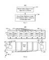
- FIG. 6depicts an exemplary embodiment of a method for fabricating an EAMR disk drive.
- FIG. 7depicts an exemplary embodiment of a method for actively aligning a slider and a laser in an EAMR disk drive.
- FIG. 8depicts an exemplary embodiment of a slider bar and a laser bar for EAMR disk drives.
- FIG. 9depicts another exemplary embodiment of a method for fabricating an EAMR disk drive.
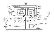
- FIG. 3is a diagram depicting a portion of an EAMR disk drive 100 .
- FIG. 3is not to scale. For simplicity not all portions of the EAMR disk drive 100 are shown.
- the disk drive 100is depicted in the context of particular components other and/or different components may be used.
- single components, such as lasers,are shown, multiple components may be used in other embodiments. Further, the arrangement of components may vary in different embodiments.
- the EAMR disk drive 100includes media (not shown) and an EAMR head 110 .
- the EAMR head 110includes a slider 104 , EAMR transducer 112 , alignment waveguide 120 , optional output device 130 , and laser 140 that is optically coupled with the EAMR transducer 112 .
- the laser 140is a laser diode that is coupled to the submount 150 . Although shown as coupled with the back side of the slider 104 , the laser 140 may be located elsewhere.
- the laser 140is a multi-emitter laser. In the embodiment shown, the laser 140 includes two emitters 142 and 144 . Main emitter 142 outputs laser beam 143 , while alignment emitter 144 provides laser beam 145 .
- the relevant portions of the emitters 142 and 144are separated by a distance, d.
- the spacing dis desired to be sufficiently large that one emitter 142 or 144 does not impact performance of the other emitter 144 or 142 , respectively. In some embodiments, this spacing is 10-20 microns. However, in other embodiments, particularly where the emitters may be independently powered, the emitters 142 and 144 may have a different spacing. For example, in some embodiments, the emitters 142 and 144 may be spaced apart by as little as 5 microns or less. In some embodiments, the main emitter 142 and alignment emitter 144 are configured to be powered independently.
- the alignment emitter 144might be on while the main emitter 142 is off, or vice versa. Further, the alignment emitter 144 and main emitter 142 might both be powered on. In other embodiments, the emitters 142 and 144 cannot be powered independently.
- the EAMR transducer 112typically includes components used to magnetically write to the media such as pole(s), shield(s), coil(s), an input grating, and, in some embodiments, a near-field transducer (NFT).
- the EAMR transducer 112also includes a waveguide 114 that is aligned with the main emitter 142 .
- the waveguide 114is aligned with the laser beam 143 of the main emitter 142 and directs energy in the laser beam 143 toward the ABS.
- energytypically in the form of light is emitted from the main emitter 142 and coupled into the waveguide 114 of the EAMR transducer 112 .
- a gratingmay be used to couple the energy from the main emitter 112 .
- the waveguide 112directs the energy toward an NFT (not shown) that resides at or near the ABA.
- the NFTcouples energy to the media. Coils (not shown) energize the pole (not shown), which magnetically writes to the heated
- the slider 104includes at least one alignment waveguide, at least one output device, and an ABS.
- a single alignment waveguide 120 and a single output device 130are shown.
- the alignment waveguide 120is aligned with the alignment emitter 144 .
- the alignment waveguide 120is also precisely spaced from the waveguide 114 .
- the alignment waveguide 120is the same distance from the waveguide 114 as the alignment emitter 144 is from the main emitter 142 .
- the alignment waveguide 120may be aligned with the laser beam 145 from the alignment emitter 144 when the waveguide 114 is aligned with the laser beam 143 from the main emitter 142 .
- the alignment waveguide 120directs energy in the laser beam 145 to the output device 130 .
- the alignment waveguide 120is identical to the waveguide 114 except in length and that the alignment waveguide 120 may terminate at the output device 130 .
- the output device 130couples the energy provided by the alignment waveguide 120 out. Thus, the energy from the alignment emitter 144 may be monitored through the output device 130 .
- the output device 130is an output grating.
- the slider 104also includes fiducial marks 116 . In the embodiment shown, fiducial marks 116 are only shown proximate to the alignment waveguide 120 . However, in other embodiments, the fiducial marks 116 may be located elsewhere.
- the alignment emitter 144 , alignment waveguide 120 , output device 130 and optional fiducial marks 116may be used in aligning the laser 140 with the slider 104 .
- the fiducial marks 116may be used to passively align the laser 140 with the slider 104 . More specifically, the fiducial marks 116 may be used in passively aligning the alignment emitter 144 with the alignment waveguide 120 . Thus, a rough alignment can be accomplished.
- the alignment emitter 144 , alignment waveguide 120 , and output device 120may be used to actively align the laser 140 with the slider 104 .
- the alignment emitter 144is energized during active alignment.
- the alignment waveguide 120directs the energy from the alignment emitter 144 to the output device 130 .
- the energy from the output device 130may be relatively easily monitored, for example via a photodetector (not shown). When the energy output by the output device 130 exceeds a threshold or is within a tolerance of a maximum, the alignment emitter 144 is sufficiently aligned with the alignment waveguide 120 .
- the distance between the alignment emitter 144 and the main emitter 142is substantially the same as the distance between the alignment waveguide 120 and the waveguide 114 .
- aligning the alignment emitter 144 with the alignment waveguide 120also aligns the waveguide 114 with the main emitter 142 . Consequently, the quality and ease of alignment of the laser 140 with the EAMR transducer 112 may be improved.
- the alignment laser 144may be independently powered. Thus, during operation of the EAMR disk drive, the alignment emitter 144 may be turned off while the main emitter 142 is used in magnetic recording. Thus, the benefits in alignment may be achieved via the alignment emitter 144 without adversely affecting later performance. Manufacturability and performance of the EAMR transducer 112 may thus be improved.
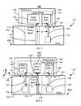
- FIG. 4is a diagram depicting a portion of an EAMR disk drive 100 ′.
- FIG. 4is not to scale. For simplicity not all portions of the EAMR disk drive 100 ′ are shown.
- the disk drive 100 ′is depicted in the context of particular components other and/or different components may be used.
- single components, such as lasersare shown, multiple components may be used in other embodiments. Further, the arrangement of components may vary in different embodiments.
- the EAMR disk drive 100 ′includes components analogous to those in the EAMR disk drive 100 .
- the EAMR disk drive 100 ′thus has an EAMR head 110 ′ including a slider 104 ′, EAMR transducer 112 ′, alignment waveguide 120 ′, output device 130 ′, and laser 140 ′ that is optically coupled with the EAMR transducer 112 ′.
- the laser 140 ′is a laser diode that is coupled to the submount 150 ′. Although shown as coupled with the back side of the slider 104 ′, the laser 140 ′ may be located elsewhere.
- the laser 140 ′is a multi-emitter laser. In the embodiment shown, the laser 140 ′ includes three emitters 142 ′, 144 ′, and 146 . Main emitter 142 ′ corresponds to the main emitter 142 .
- the main emitter 142 ′resides between alignment emitters 144 ′ and 146 .
- the alignment emitters 144 ′ and 146are separated from the main emitter 142 ′ by distances d 1 and d 2 , respectively.
- the spacings d 1 and d 2are desired to be sufficiently large that one emitter 142 ′, 144 ′, or 146 does not impact performance of the other emitters 142 ′, 144 ′, or 146 . In some embodiments, this spacing is 10-20 microns. However, in other embodiments, particularly where the emitters may be independently powered, the emitters 142 ′, 144 ′, and 146 may have a different spacing.
- the emitters 142 ′, 144 ′, and 146may be spaced apart by as little as 5 microns or less. In the embodiment shown, the spacings d 1 and d 2 are shown as different. In other embodiments, the spacing d 1 and d 2 may be the same.
- the main emitter 142 ′ and alignment emitters 144 ′ and 146are configured to be powered independently. For example, the alignment emitters 144 ′ and/or 146 might be on while the main emitter 142 ′ is off, or vice versa. Further, the alignment emitters 144 ′ and/or 146 and main emitter 142 ′ might both be powered on. In other embodiments, the emitters 142 ′, 144 ′, and 146 cannot be powered independently.
- the EAMR transducer 112 ′includes components used to magnetically write to the media such as pole(s), shield(s), coil(s), an input grating, and, in some embodiments, an NFT.
- the EAMR transducer 112 ′also includes a waveguide 114 ′ that is aligned with the main emitter 142 ′.
- the waveguide 114 ′is thus analogous to the waveguide 114 .
- the EAMR transducer 112 ′also functions in an analogous manner to the transducer 112 .
- the slider 104 ′includes alignment waveguides 120 ′ and 122 as well as output devices 130 ′ and 132 .
- the alignment waveguide 120 ′is aligned with the alignment emitter 144 ′.
- the alignment waveguide 122is aligned with alignment emitter 146 .
- the alignment waveguides 120 ′ and 122are also precisely spaced from the waveguide 114 ′.
- the alignment waveguides 120 ′ and 122are the same distances, d 1 and d 2 , from the waveguide 114 ′ as the alignment emitters 144 ′ and 146 are from the main emitter 142 ′.
- the alignment waveguides 120 ′ and 122direct energy in the laser beams 145 ′ and 147 to the output devices 130 ′ and 132 , respectively.
- the alignment waveguides 120 ′ and 122are identical to the waveguide 114 ′ except in length and that the alignment waveguides 120 ′ and 122 may terminate at the output device 130 ′ and 132 , respectively.
- the output devices 130 ′ and 132couple out the energy provided by the alignment waveguides 120 ′ and 122 , respectively.
- each of the output devices 130 ′ and 132is an output grating.
- the slider 104 ′also includes fiducial marks 116 ′ and 118 . In the embodiment shown, fiducial marks 116 ′ and 118 are only shown proximate to the alignment waveguides 120 ′ and 122 , respectively. However, in other embodiments, the fiducial marks 116 ′ and 118 may be located elsewhere.
- the alignment emitters 144 ′ and 146 , alignment waveguides 120 ′ and 122 , output devices 130 ′ and 132 , and optional fiducial marks 116 ′ and 118may be used in aligning the laser 140 ′ with the slider 104 ′.
- the fiducial marks 116 ′ and 118 ′may be used to passively align the laser 140 ′ with the slider 104 ′.
- the alignment emitters 144 and 146 , alignment waveguides 120 ′ and 122 , and output devices 120 ′ and 122may be used to actively align the laser 140 with the slider 104 . This may be accomplished in a manner analogous to that used for the EAMR disk drive 100 . However, two alignment waveguides 120 ′ and 122 are used.
- alignment in the y direction and the x direction as shown in FIG. 4may be improved.
- rotations in the x-y plane of the laser 140 ′ with respect to the slider 104 ′ around an axis close to the alignment waveguide 144 ′may be accounted for. Consequently, the quality and ease of alignment of the laser 140 ′ with the EAMR transducer 112 ′ may be improved.
- Manufacturability and performance of the EAMR transducer 112 ′may thus be improved.
- the alignment emitter 144 ′/ 146may be independently powered. Thus, the alignment emitters 144 ′ and 146 may be turned off during regular operation of the EAMR disk drive 100 ′. Thus, these improvements in alignment may be achieved without adversely affecting later performance.
- FIG. 5is a diagram depicting a portion of an EAMR disk drive 100 ′′.
- FIG. 5is not to scale. For simplicity not all portions of the EAMR disk drive 100 ′′ are shown.
- the disk drive 100 ′′is depicted in the context of particular components other and/or different components may be used.
- single components, such as lasersare shown, multiple components may be used in other embodiments. Further, the arrangement of components may vary in different embodiments.
- the EAMR disk drive 100 ′′includes components analogous to those in the EAMR disk drive 100 and 100 ′.
- the EAMR disk drive 100 ′′includes components 104 ′′, 110 ′′, 112 ′′, 114 ′′, 116 ′′, 118 ′, 120 ′′, 122 ′, 130 ′′, 132 ′, 140 ′′, 142 ′′, 143 ′′, 144 ′′, 145 ′′, 146 ′, 147 ′ and 150 ′′ correspond to the components 104 ′, 110 ′, 112 ′, 114 ′, 116 ′, 118 , 120 ′, 122 , 130 ′, 132 , 140 ′, 142 ′, 143 ′, 144 ′, 145 ′, 146 , 147 , and 150 , respectively.
- the alignment emitters 144 ′ and 146 ′are both on the same side of the main emitter 142 ′′.
- the alignment waveguides 120 ′′ and 122 ′are on the same side of the waveguide 114 ′′.
- the function of the EAMR transducer 112 ′′, main emitter 142 ′′, alignment emitters 144 ′′ and 146 ′, alignment waveguides 120 ′′ and 122 ′, and output devices 130 ′′ and 132 ′, respectively,are substantially the same as in the EAMR disk drive 100 ′. More specifically, use of the two alignment waveguides 120 ′′ and 122 ′ may improve alignment over the use of a single alignment waveguide.
- alignment in the y direction and the x direction as shown in FIG. 6may be improved.
- rotations in the x-y plane of the laser 140 ′ with respect to the slider 104 ′ around an axis close to the alignment waveguide 144 ′may be accounted for. Consequently, the quality and ease of alignment of the laser 140 ′ with the EAMR transducer 112 ′′ may be improved.
- Manufacturability and performance of the EAMR transducer 112 ′/may thus be improved.
- the alignment emitter 144 ′′/ 146 ′may be independently powered.
- the alignment emitters 144 ′′ and 146 ′may be turned off during regular operation of the EAMR disk drive 100 ′′.
- these improvements in alignmentmay be achieved without adversely affecting later performance.
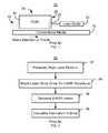
- FIG. 6depicts an exemplary embodiment of a method 200 of forming a portion of an EAMR disk drive. For simplicity, some steps may be omitted, combined, performed in parallel, performed in another sequence, and/or interleaved.
- the method 200is described in the context of the EAMR disk drives 100 / 100 ′/ 100 ′′. However, the method 200 may be used to fabricate other EAMR disk drives. In addition, the method 200 is described in the context of fabricating a single disk drive 100 / 100 ′/ 100 ′′. However, multiple transducers, sliders, and multiple disk drives may be fabricated substantially in parallel.
- the laser 140 / 140 ′/ 140 ′′is passively aligned with the slider 104 / 104 ′/ 104 ′′, via step 202 .
- step 202is performed using fiducials 116 / 116 ′/ 116 ′′ and 118 / 118 ′.
- another external lasermight be used.
- an external lasermight be optically coupled to the output 130 , 130 ′, 130 ′′, 132 , or 132 ′. In such a case, the light travels backwards along the waveguide 120 , 120 ′, 120 ′′, 122 , or 122 ′.
- the light from the external lasermay be detected at the input of the waveguide 120 , 120 ′, 120 ′′, 122 , or 122 ′. In essence, light from the external laser might be used as a fiducial mark. In either case, the alignment performed in step 202 is sufficient that light from the alignment emitter 144 , 144 ′, 144 ′′, 146 , and/or 146 ′ may be detected at the corresponding output 130 , 130 ′, 130 ′′, 132 , and/or 132 ′.
- a vertical separation between the alignment emitter 144 , 144 ′, 144 ′′, 146 , and/or 146 ′ and waveguide 120 , 120 ′, 120 ′′, 122 , and/or 122 ′, respectivelyis maintained during the passive alignment to improve the changes that the light in a divergent beam from the alignment emitter 312 and/or 314 may be detected.
- a rough alignment of the laser 140 / 140 ′/ 140 ′′ with the slider 104 / 140 ′/ 140 ′′may be achieved.
- the laser 140 / 140 ′/ 140 ′′is actively aligned with the EAMR transducer 112 / 112 ′/ 112 ′′, via step 204 . More specifically, the alignment laser 144 / 144 ′/ 144 ′′ and/or the alignment laser 146 / 146 ′ is energized while the power output by output device 130 / 130 ′/ 130 ′′ and/or 132 / 132 ′ is monitored. For example, a photodetector (not shown) might be used in step 204 to monitor the power output at the output device 130 / 130 ′/ 130 ′′ and/or 132 / 132 ′.
- the laser 140 / 140 ′/ 140 ′′is moved relative to the slider 104 / 104 ′/ 104 ′′ until the desired alignment is achieved. In some embodiments, this corresponds to the output power detected exceeding a threshold and/or being within a tolerance of a maximum expected power.
- the laser 140 / 140 ′/ 140 ′′′ and slider 104 / 104 ′/ 104 ′′are then affixed to each other, via step 206 .
- the EAMR disk drive 100 , 100 ′, and/or 100 ′′may be formed. Because active alignment may be easily performed, alignment may be improved. Further, the alignment emitter 144 ′/ 146 may be independently powered. Thus, the alignment emitters may be turned off during regular operation of the EAMR disk drive 100 ′′. Thus, these improvements in alignment may be achieved without adversely affecting later performance.
- FIG. 7depicts an exemplary embodiment of a method 210 for actively aligning a laser with a slider. For simplicity, some steps may be omitted, combined, performed in parallel, performed in another sequence, and/or interleaved.
- the method 210is described in the context of the EAMR disk drives 100 / 100 ′/ 100 ′′. However, the method 210 may be used to fabricate other EAMR disk drives. In addition, the method 210 is described in the context of fabricating a single disk drive 100 / 100 ′/ 100 ′′. However, multiple transducers, sliders, and multiple disk drives may be fabricated substantially in parallel.
- the method 210may commence after the laser 140 / 140 ′/ 140 ′′ and slider 104 / 104 ′/ 104 ′′ are roughly aligned, for example via a passive alignment described above. The method 210 may thus be used as part of the method 200 . Further, the method 210 commences after the alignment laser 144 / 144 ′/ 144 ′′ and/or the alignment laser 146 / 146 ′ is energized.
- An output signalis detected from the device 130 / 130 ′/ 130 ′′ and/or 132 / 132 ′, via step 212 .
- first lightis detected.
- the power output by output device 130 / 130 ′/ 130 ′′ and/or 132 / 132 ′is then monitored while the laser 140 / 140 ′/ 140 ′′ is moved relative to the slider 104 / 104 ′/ 104 ′′, via step 214 .
- a photodetector(not shown) might be used in step 214 to monitor the power output at the output device 130 / 130 ′/ 130 ′′ and/or 132 / 132 ′.
- Step 214continues until the output power detected is within a tolerance of a maximum expected power, or until the output power exceeds a threshold.
- the laser 140 / 140 ′/ 140 ′′′is then considered to be sufficiently closely aligned to the slider 104 / 104 ′/ 104 ′′.
- the components of, the EAMR disk drive 100 , 100 ′, and/or 100 ′′may be aligned. Because active alignment may be easily performed, alignment may be improved. Because the alignment emitter 144 ′/ 146 may be independently powered, this improvement may be achieved without adversely affecting later performance.
- the methods 200 and 210are described in the context of single EAMR heads 110 / 110 ′/ 110 ′′, individual sliders 104 / 104 ′/ 104 ′′, and single lasers 140 / 140 ′/ 140 ′′.
- the methods 200 and 210 and alignment lasers 144 / 144 ′/ 144 ′′ and alignment lasers 146 / 146 ′may be extended to higher level integration.
- laser bars and slider barsmay be used.
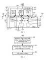
- FIG. 8is a diagram depicting a system 300 for aligning multiple EAMR heads. For clarity, FIG. 8 is not to scale.
- the system 300is depicted in the context of particular components, other and/or different components may be used.
- a particular number of lasers and slidersare shown on each bar, other numbers of lasers and/or sliders may reside on a bar. Further, the arrangement of components may vary in different embodiments.
- the system 300includes a laser bar 310 and a slider bar 320 .
- the laser bar 310includes multiple alignment emitters and multiple main emitters. In the embodiment shown, two alignment emitters 312 and 314 are used at the ends of the laser bar.
- the main emitters 316reside between the alignment emitters 312 and 314 .
- Each main emitter 316may correspond to an EAMR head being fabricated. However, in other embodiments, an alignment emitter may be provided for each main emitter 316 . In other embodiments, more alignment emitters may be provided, but their number will be less than the total number of main emitters 316 . Stated differently, it may not be necessary to provide an alignment emitter for each main emitter 316 . Further, six main emitters 316 are shown for simplicity. In other embodiments, another number of main emitters 316 may reside on a laser bar 310 .
- the slider bar 320includes multiple sliders. Each slider includes a waveguide 322 . Each waveguide may correspond to an EAMR head that has been fabricated. Thus, each waveguide 322 corresponds to a main emitter 316 . The spacing between and location of the waveguides 322 thus corresponds to the spacing between and position of the main emitters 312 . Further, waveguides 322 corresponding to six EAMR transducers are shown for simplicity. In other embodiments, another number of waveguides 322 and EAMR transducers may reside on a slider bar 320 . In addition, alignment waveguides 324 and 326 and corresponding output devices 325 and 328 are shown.
- an alignment waveguide 324 and 326corresponds to each alignment emitter 312 and 314 , respectively.
- the spacing between and position of the alignment waveguides 324 and 326thus corresponds to the spacing between and position of the alignment emitters 312 .
- bar-to-bar alignmentmay be carried out.
- active alignmentmay be more easily performed using the alignment emitters 312 / 314 and alignment waveguides 324 / 326 .
- the alignment in the x-y planemay be better achieved.
- additional alignment emitters and alignment waveguidesare included, the active alignment in the x-y plane may be performed even if there is a failure in one of the alignment emitters 312 / 314 or alignment waveguides 324 / 326 .
- fabrication of EAMR headsmay be improved.
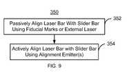
- FIG. 9depicts an exemplary embodiment of a method 350 for using an EAMR disk drive. For simplicity, some steps may be omitted, combined, performed in parallel, performed in another sequence, and/or interleaved.
- the method 350is described in the context of the system 300 . However, the method 350 may be used to fabricate other EAMR disk drives.
- step 352is performed using fiducials 323 and/or 327 .
- another external lasermight be used.
- an external lasermight be optically coupled to the output 325 and/or 328 . In such a case, the light travels backwards along the waveguide 324 and/or 326 .
- the light from the external lasermay be detected at the input of the waveguide 324 and/or 326 .
- the alignment performed in step 352is sufficient that light from the alignment emitter 312 and/or 314 may be detected at the corresponding output 325 and/or 328 , respectively.
- a separation between the laser bar 310 and slider bar 320is maintained during the passive alignment to improve the changes that the light in a divergent beam from the alignment emitter 312 and/or 314 may be detected. In step 352 , therefore, a rough alignment of the laser bar 310 with the slider bar 320 may be achieved.
- the laser bar 310is actively aligned with the slider bar 320 , via step 354 . More specifically, the alignment laser 312 and/or the alignment laser 314 are energized while the power output by output device 325 and/or 328 is monitored. For example, a photodetector (not shown) might be used in step 354 to monitor the power output at the output device 325 and/or 328 .
- the laser bar 310is moved relative to the slider bar 320 until the output power detected exceeds a threshold and/or is within a tolerance of a maximum expected power.
- the laser bar 310 and slider bar 320may then be affixed to each other.
- bar-to-bar active alignmentmay be more easily achieved. Because active alignment may be easily performed, alignment may be improved. Thus, fabrication and performance of the EAMR heads being formed may be improved.
Landscapes
- Engineering & Computer Science (AREA)
- Manufacturing & Machinery (AREA)
- Recording Or Reproducing By Magnetic Means (AREA)
- Adjustment Of The Magnetic Head Position Track Following On Tapes (AREA)
- Magnetic Heads (AREA)
- Optical Couplings Of Light Guides (AREA)
Abstract
Description
Claims (21)
Priority Applications (2)
| Application Number | Priority Date | Filing Date | Title |
|---|---|---|---|
| US12/976,770US8593914B2 (en) | 2010-12-22 | 2010-12-22 | Method and system for optically coupling a laser with a transducer in an energy assisted magnetic recording disk drive |
| CN201110448575.6ACN102543106B (en) | 2010-12-22 | 2011-12-22 | The method and system of laser instrument and sensor is coupled optically in energy assisted magnetic recording disk drive |
Applications Claiming Priority (1)
| Application Number | Priority Date | Filing Date | Title |
|---|---|---|---|
| US12/976,770US8593914B2 (en) | 2010-12-22 | 2010-12-22 | Method and system for optically coupling a laser with a transducer in an energy assisted magnetic recording disk drive |
Publications (2)
| Publication Number | Publication Date |
|---|---|
| US20120163137A1 US20120163137A1 (en) | 2012-06-28 |
| US8593914B2true US8593914B2 (en) | 2013-11-26 |
Family
ID=46316631
Family Applications (1)
| Application Number | Title | Priority Date | Filing Date |
|---|---|---|---|
| US12/976,770Active2031-11-14US8593914B2 (en) | 2010-12-22 | 2010-12-22 | Method and system for optically coupling a laser with a transducer in an energy assisted magnetic recording disk drive |
Country Status (2)
| Country | Link |
|---|---|
| US (1) | US8593914B2 (en) |
| CN (1) | CN102543106B (en) |
Cited By (136)
| Publication number | Priority date | Publication date | Assignee | Title |
|---|---|---|---|---|
| US8830628B1 (en) | 2009-02-23 | 2014-09-09 | Western Digital (Fremont), Llc | Method and system for providing a perpendicular magnetic recording head |
| US8842506B1 (en)* | 2013-08-27 | 2014-09-23 | HGST Netherlands B.V. | Heat-assisted magnetic recording (HAMR) disk drive with fly-height sensing |
| US8879207B1 (en) | 2011-12-20 | 2014-11-04 | Western Digital (Fremont), Llc | Method for providing a side shield for a magnetic recording transducer using an air bridge |
| US8883017B1 (en) | 2013-03-12 | 2014-11-11 | Western Digital (Fremont), Llc | Method and system for providing a read transducer having seamless interfaces |
| US8897102B1 (en) | 2013-04-02 | 2014-11-25 | Western Digital (Fremont), Llc | Method and system for measuring light delivery offsets in a heat assisted magnetic recording head |
| US8917581B1 (en) | 2013-12-18 | 2014-12-23 | Western Digital Technologies, Inc. | Self-anneal process for a near field transducer and chimney in a hard disk drive assembly |
| US8923102B1 (en) | 2013-07-16 | 2014-12-30 | Western Digital (Fremont), Llc | Optical grating coupling for interferometric waveguides in heat assisted magnetic recording heads |
| US8947985B1 (en) | 2013-07-16 | 2015-02-03 | Western Digital (Fremont), Llc | Heat assisted magnetic recording transducers having a recessed pole |
| US8953422B1 (en) | 2014-06-10 | 2015-02-10 | Western Digital (Fremont), Llc | Near field transducer using dielectric waveguide core with fine ridge feature |
| US8958271B1 (en)* | 2013-09-03 | 2015-02-17 | Seagate Technology Llc | Peg height of near-field transducers |
| US8958272B1 (en) | 2014-06-10 | 2015-02-17 | Western Digital (Fremont), Llc | Interfering near field transducer for energy assisted magnetic recording |
| US8970988B1 (en) | 2013-12-31 | 2015-03-03 | Western Digital (Fremont), Llc | Electric gaps and method for making electric gaps for multiple sensor arrays |
| US8971160B1 (en) | 2013-12-19 | 2015-03-03 | Western Digital (Fremont), Llc | Near field transducer with high refractive index pin for heat assisted magnetic recording |
| US8976635B1 (en) | 2014-06-10 | 2015-03-10 | Western Digital (Fremont), Llc | Near field transducer driven by a transverse electric waveguide for energy assisted magnetic recording |
| US8980109B1 (en) | 2012-12-11 | 2015-03-17 | Western Digital (Fremont), Llc | Method for providing a magnetic recording transducer using a combined main pole and side shield CMP for a wraparound shield scheme |
| US8982508B1 (en) | 2011-10-31 | 2015-03-17 | Western Digital (Fremont), Llc | Method for providing a side shield for a magnetic recording transducer |
| US8988825B1 (en) | 2014-02-28 | 2015-03-24 | Western Digital (Fremont, LLC | Method for fabricating a magnetic writer having half-side shields |
| US8984740B1 (en) | 2012-11-30 | 2015-03-24 | Western Digital (Fremont), Llc | Process for providing a magnetic recording transducer having a smooth magnetic seed layer |
| US8988812B1 (en) | 2013-11-27 | 2015-03-24 | Western Digital (Fremont), Llc | Multi-sensor array configuration for a two-dimensional magnetic recording (TDMR) operation |
| US8993217B1 (en) | 2013-04-04 | 2015-03-31 | Western Digital (Fremont), Llc | Double exposure technique for high resolution disk imaging |
| US8995087B1 (en) | 2006-11-29 | 2015-03-31 | Western Digital (Fremont), Llc | Perpendicular magnetic recording write head having a wrap around shield |
| US9001628B1 (en) | 2013-12-16 | 2015-04-07 | Western Digital (Fremont), Llc | Assistant waveguides for evaluating main waveguide coupling efficiency and diode laser alignment tolerances for hard disk |
| US8997832B1 (en) | 2010-11-23 | 2015-04-07 | Western Digital (Fremont), Llc | Method of fabricating micrometer scale components |
| US9001467B1 (en) | 2014-03-05 | 2015-04-07 | Western Digital (Fremont), Llc | Method for fabricating side shields in a magnetic writer |
| US9007879B1 (en) | 2014-06-10 | 2015-04-14 | Western Digital (Fremont), Llc | Interfering near field transducer having a wide metal bar feature for energy assisted magnetic recording |
| US9007719B1 (en) | 2013-10-23 | 2015-04-14 | Western Digital (Fremont), Llc | Systems and methods for using double mask techniques to achieve very small features |
| US9007725B1 (en) | 2014-10-07 | 2015-04-14 | Western Digital (Fremont), Llc | Sensor with positive coupling between dual ferromagnetic free layer laminates |
| US9013836B1 (en) | 2013-04-02 | 2015-04-21 | Western Digital (Fremont), Llc | Method and system for providing an antiferromagnetically coupled return pole |
| US9042057B1 (en) | 2013-01-09 | 2015-05-26 | Western Digital (Fremont), Llc | Methods for providing magnetic storage elements with high magneto-resistance using Heusler alloys |
| US9042058B1 (en) | 2013-10-17 | 2015-05-26 | Western Digital Technologies, Inc. | Shield designed for middle shields in a multiple sensor array |
| US9042051B2 (en) | 2013-08-15 | 2015-05-26 | Western Digital (Fremont), Llc | Gradient write gap for perpendicular magnetic recording writer |
| US9042052B1 (en) | 2014-06-23 | 2015-05-26 | Western Digital (Fremont), Llc | Magnetic writer having a partially shunted coil |
| US9042208B1 (en) | 2013-03-11 | 2015-05-26 | Western Digital Technologies, Inc. | Disk drive measuring fly height by applying a bias voltage to an electrically insulated write component of a head |
| US9042048B1 (en) | 2014-09-30 | 2015-05-26 | Western Digital (Fremont), Llc | Laser-ignited reactive HAMR bonding |
| US9053735B1 (en) | 2014-06-20 | 2015-06-09 | Western Digital (Fremont), Llc | Method for fabricating a magnetic writer using a full-film metal planarization |
| US9064527B1 (en) | 2013-04-12 | 2015-06-23 | Western Digital (Fremont), Llc | High order tapered waveguide for use in a heat assisted magnetic recording head |
| US9064507B1 (en) | 2009-07-31 | 2015-06-23 | Western Digital (Fremont), Llc | Magnetic etch-stop layer for magnetoresistive read heads |
| US9065043B1 (en) | 2012-06-29 | 2015-06-23 | Western Digital (Fremont), Llc | Tunnel magnetoresistance read head with narrow shield-to-shield spacing |
| US9064528B1 (en) | 2013-05-17 | 2015-06-23 | Western Digital Technologies, Inc. | Interferometric waveguide usable in shingled heat assisted magnetic recording in the absence of a near-field transducer |
| US9070381B1 (en) | 2013-04-12 | 2015-06-30 | Western Digital (Fremont), Llc | Magnetic recording read transducer having a laminated free layer |
| US9082423B1 (en) | 2013-12-18 | 2015-07-14 | Western Digital (Fremont), Llc | Magnetic recording write transducer having an improved trailing surface profile |
| US9087527B1 (en) | 2014-10-28 | 2015-07-21 | Western Digital (Fremont), Llc | Apparatus and method for middle shield connection in magnetic recording transducers |
| US9087534B1 (en) | 2011-12-20 | 2015-07-21 | Western Digital (Fremont), Llc | Method and system for providing a read transducer having soft and hard magnetic bias structures |
| US9093639B2 (en) | 2012-02-21 | 2015-07-28 | Western Digital (Fremont), Llc | Methods for manufacturing a magnetoresistive structure utilizing heating and cooling |
| US9104107B1 (en) | 2013-04-03 | 2015-08-11 | Western Digital (Fremont), Llc | DUV photoresist process |
| US9111558B1 (en) | 2014-03-14 | 2015-08-18 | Western Digital (Fremont), Llc | System and method of diffractive focusing of light in a waveguide |
| US9111564B1 (en) | 2013-04-02 | 2015-08-18 | Western Digital (Fremont), Llc | Magnetic recording writer having a main pole with multiple flare angles |
| US9111550B1 (en) | 2014-12-04 | 2015-08-18 | Western Digital (Fremont), Llc | Write transducer having a magnetic buffer layer spaced between a side shield and a write pole by non-magnetic layers |
| US9123362B1 (en) | 2011-03-22 | 2015-09-01 | Western Digital (Fremont), Llc | Methods for assembling an electrically assisted magnetic recording (EAMR) head |
| US9123358B1 (en) | 2012-06-11 | 2015-09-01 | Western Digital (Fremont), Llc | Conformal high moment side shield seed layer for perpendicular magnetic recording writer |
| US9123374B1 (en) | 2015-02-12 | 2015-09-01 | Western Digital (Fremont), Llc | Heat assisted magnetic recording writer having an integrated polarization rotation plate |
| US9123359B1 (en) | 2010-12-22 | 2015-09-01 | Western Digital (Fremont), Llc | Magnetic recording transducer with sputtered antiferromagnetic coupling trilayer between plated ferromagnetic shields and method of fabrication |
| US9135937B1 (en) | 2014-05-09 | 2015-09-15 | Western Digital (Fremont), Llc | Current modulation on laser diode for energy assisted magnetic recording transducer |
| US9135930B1 (en) | 2014-03-06 | 2015-09-15 | Western Digital (Fremont), Llc | Method for fabricating a magnetic write pole using vacuum deposition |
| US9142233B1 (en) | 2014-02-28 | 2015-09-22 | Western Digital (Fremont), Llc | Heat assisted magnetic recording writer having a recessed pole |
| US9147404B1 (en) | 2015-03-31 | 2015-09-29 | Western Digital (Fremont), Llc | Method and system for providing a read transducer having a dual free layer |
| US9147408B1 (en) | 2013-12-19 | 2015-09-29 | Western Digital (Fremont), Llc | Heated AFM layer deposition and cooling process for TMR magnetic recording sensor with high pinning field |
| US9153255B1 (en) | 2014-03-05 | 2015-10-06 | Western Digital (Fremont), Llc | Method for fabricating a magnetic writer having an asymmetric gap and shields |
| US9183854B2 (en) | 2014-02-24 | 2015-11-10 | Western Digital (Fremont), Llc | Method to make interferometric taper waveguide for HAMR light delivery |
| US9190085B1 (en) | 2014-03-12 | 2015-11-17 | Western Digital (Fremont), Llc | Waveguide with reflective grating for localized energy intensity |
| US9190079B1 (en) | 2014-09-22 | 2015-11-17 | Western Digital (Fremont), Llc | Magnetic write pole having engineered radius of curvature and chisel angle profiles |
| US9194692B1 (en) | 2013-12-06 | 2015-11-24 | Western Digital (Fremont), Llc | Systems and methods for using white light interferometry to measure undercut of a bi-layer structure |
| US9202493B1 (en) | 2014-02-28 | 2015-12-01 | Western Digital (Fremont), Llc | Method of making an ultra-sharp tip mode converter for a HAMR head |
| US9202480B2 (en) | 2009-10-14 | 2015-12-01 | Western Digital (Fremont), LLC. | Double patterning hard mask for damascene perpendicular magnetic recording (PMR) writer |
| US9214169B1 (en) | 2014-06-20 | 2015-12-15 | Western Digital (Fremont), Llc | Magnetic recording read transducer having a laminated free layer |
| US9214172B2 (en) | 2013-10-23 | 2015-12-15 | Western Digital (Fremont), Llc | Method of manufacturing a magnetic read head |
| US9213322B1 (en) | 2012-08-16 | 2015-12-15 | Western Digital (Fremont), Llc | Methods for providing run to run process control using a dynamic tuner |
| US9214165B1 (en) | 2014-12-18 | 2015-12-15 | Western Digital (Fremont), Llc | Magnetic writer having a gradient in saturation magnetization of the shields |
| US9230565B1 (en) | 2014-06-24 | 2016-01-05 | Western Digital (Fremont), Llc | Magnetic shield for magnetic recording head |
| US9236560B1 (en) | 2014-12-08 | 2016-01-12 | Western Digital (Fremont), Llc | Spin transfer torque tunneling magnetoresistive device having a laminated free layer with perpendicular magnetic anisotropy |
| US9245543B1 (en) | 2010-06-25 | 2016-01-26 | Western Digital (Fremont), Llc | Method for providing an energy assisted magnetic recording head having a laser integrally mounted to the slider |
| US9245562B1 (en) | 2015-03-30 | 2016-01-26 | Western Digital (Fremont), Llc | Magnetic recording writer with a composite main pole |
| US9245545B1 (en) | 2013-04-12 | 2016-01-26 | Wester Digital (Fremont), Llc | Short yoke length coils for magnetic heads in disk drives |
| US9251813B1 (en) | 2009-04-19 | 2016-02-02 | Western Digital (Fremont), Llc | Method of making a magnetic recording head |
| US9263067B1 (en) | 2013-05-29 | 2016-02-16 | Western Digital (Fremont), Llc | Process for making PMR writer with constant side wall angle |
| US9263071B1 (en) | 2015-03-31 | 2016-02-16 | Western Digital (Fremont), Llc | Flat NFT for heat assisted magnetic recording |
| US9269382B1 (en) | 2012-06-29 | 2016-02-23 | Western Digital (Fremont), Llc | Method and system for providing a read transducer having improved pinning of the pinned layer at higher recording densities |
| US9275657B1 (en) | 2013-08-14 | 2016-03-01 | Western Digital (Fremont), Llc | Process for making PMR writer with non-conformal side gaps |
| US9280990B1 (en) | 2013-12-11 | 2016-03-08 | Western Digital (Fremont), Llc | Method for fabricating a magnetic writer using multiple etches |
| US9287494B1 (en) | 2013-06-28 | 2016-03-15 | Western Digital (Fremont), Llc | Magnetic tunnel junction (MTJ) with a magnesium oxide tunnel barrier |
| US9286919B1 (en) | 2014-12-17 | 2016-03-15 | Western Digital (Fremont), Llc | Magnetic writer having a dual side gap |
| US9305583B1 (en) | 2014-02-18 | 2016-04-05 | Western Digital (Fremont), Llc | Method for fabricating a magnetic writer using multiple etches of damascene materials |
| US9312064B1 (en) | 2015-03-02 | 2016-04-12 | Western Digital (Fremont), Llc | Method to fabricate a magnetic head including ion milling of read gap using dual layer hard mask |
| US9318130B1 (en) | 2013-07-02 | 2016-04-19 | Western Digital (Fremont), Llc | Method to fabricate tunneling magnetic recording heads with extended pinned layer |
| US9336814B1 (en) | 2013-03-12 | 2016-05-10 | Western Digital (Fremont), Llc | Inverse tapered waveguide for use in a heat assisted magnetic recording head |
| US9343098B1 (en) | 2013-08-23 | 2016-05-17 | Western Digital (Fremont), Llc | Method for providing a heat assisted magnetic recording transducer having protective pads |
| US9343087B1 (en) | 2014-12-21 | 2016-05-17 | Western Digital (Fremont), Llc | Method for fabricating a magnetic writer having half shields |
| US9343086B1 (en) | 2013-09-11 | 2016-05-17 | Western Digital (Fremont), Llc | Magnetic recording write transducer having an improved sidewall angle profile |
| US9349392B1 (en) | 2012-05-24 | 2016-05-24 | Western Digital (Fremont), Llc | Methods for improving adhesion on dielectric substrates |
| US9349394B1 (en) | 2013-10-18 | 2016-05-24 | Western Digital (Fremont), Llc | Method for fabricating a magnetic writer having a gradient side gap |
| US9361913B1 (en) | 2013-06-03 | 2016-06-07 | Western Digital (Fremont), Llc | Recording read heads with a multi-layer AFM layer methods and apparatuses |
| US9361914B1 (en) | 2014-06-18 | 2016-06-07 | Western Digital (Fremont), Llc | Magnetic sensor with thin capping layer |
| US9368134B1 (en) | 2010-12-16 | 2016-06-14 | Western Digital (Fremont), Llc | Method and system for providing an antiferromagnetically coupled writer |
| US9384763B1 (en) | 2015-03-26 | 2016-07-05 | Western Digital (Fremont), Llc | Dual free layer magnetic reader having a rear bias structure including a soft bias layer |
| US9384765B1 (en) | 2015-09-24 | 2016-07-05 | Western Digital (Fremont), Llc | Method and system for providing a HAMR writer having improved optical efficiency |
| US9396743B1 (en) | 2014-02-28 | 2016-07-19 | Western Digital (Fremont), Llc | Systems and methods for controlling soft bias thickness for tunnel magnetoresistance readers |
| US9396742B1 (en) | 2012-11-30 | 2016-07-19 | Western Digital (Fremont), Llc | Magnetoresistive sensor for a magnetic storage system read head, and fabrication method thereof |
| US9406331B1 (en) | 2013-06-17 | 2016-08-02 | Western Digital (Fremont), Llc | Method for making ultra-narrow read sensor and read transducer device resulting therefrom |
| US9424866B1 (en) | 2015-09-24 | 2016-08-23 | Western Digital (Fremont), Llc | Heat assisted magnetic recording write apparatus having a dielectric gap |
| US9431047B1 (en) | 2013-05-01 | 2016-08-30 | Western Digital (Fremont), Llc | Method for providing an improved AFM reader shield |
| US9431039B1 (en) | 2013-05-21 | 2016-08-30 | Western Digital (Fremont), Llc | Multiple sensor array usable in two-dimensional magnetic recording |
| US9431038B1 (en) | 2015-06-29 | 2016-08-30 | Western Digital (Fremont), Llc | Method for fabricating a magnetic write pole having an improved sidewall angle profile |
| US9431032B1 (en) | 2013-08-14 | 2016-08-30 | Western Digital (Fremont), Llc | Electrical connection arrangement for a multiple sensor array usable in two-dimensional magnetic recording |
| US9431031B1 (en) | 2015-03-24 | 2016-08-30 | Western Digital (Fremont), Llc | System and method for magnetic transducers having multiple sensors and AFC shields |
| US9437251B1 (en) | 2014-12-22 | 2016-09-06 | Western Digital (Fremont), Llc | Apparatus and method having TDMR reader to reader shunts |
| US9441938B1 (en) | 2013-10-08 | 2016-09-13 | Western Digital (Fremont), Llc | Test structures for measuring near field transducer disc length |
| US9443541B1 (en) | 2015-03-24 | 2016-09-13 | Western Digital (Fremont), Llc | Magnetic writer having a gradient in saturation magnetization of the shields and return pole |
| US9449625B1 (en) | 2014-12-24 | 2016-09-20 | Western Digital (Fremont), Llc | Heat assisted magnetic recording head having a plurality of diffusion barrier layers |
| US9449621B1 (en) | 2015-03-26 | 2016-09-20 | Western Digital (Fremont), Llc | Dual free layer magnetic reader having a rear bias structure having a high aspect ratio |
| US9472216B1 (en) | 2015-09-23 | 2016-10-18 | Western Digital (Fremont), Llc | Differential dual free layer magnetic reader |
| US9484051B1 (en) | 2015-11-09 | 2016-11-01 | The Provost, Fellows, Foundation Scholars and the other members of Board, of the College of the Holy and Undivided Trinity of Queen Elizabeth near Dublin | Method and system for reducing undesirable reflections in a HAMR write apparatus |
| US9508363B1 (en) | 2014-06-17 | 2016-11-29 | Western Digital (Fremont), Llc | Method for fabricating a magnetic write pole having a leading edge bevel |
| US9508372B1 (en) | 2015-06-03 | 2016-11-29 | Western Digital (Fremont), Llc | Shingle magnetic writer having a low sidewall angle pole |
| US9508365B1 (en) | 2015-06-24 | 2016-11-29 | Western Digital (Fremont), LLC. | Magnetic reader having a crystal decoupling structure |
| US9530443B1 (en) | 2015-06-25 | 2016-12-27 | Western Digital (Fremont), Llc | Method for fabricating a magnetic recording device having a high aspect ratio structure |
| US9564150B1 (en) | 2015-11-24 | 2017-02-07 | Western Digital (Fremont), Llc | Magnetic read apparatus having an improved read sensor isolation circuit |
| US9595273B1 (en) | 2015-09-30 | 2017-03-14 | Western Digital (Fremont), Llc | Shingle magnetic writer having nonconformal shields |
| US9646639B2 (en) | 2015-06-26 | 2017-05-09 | Western Digital (Fremont), Llc | Heat assisted magnetic recording writer having integrated polarization rotation waveguides |
| US9666214B1 (en) | 2015-09-23 | 2017-05-30 | Western Digital (Fremont), Llc | Free layer magnetic reader that may have a reduced shield-to-shield spacing |
| US9721595B1 (en) | 2014-12-04 | 2017-08-01 | Western Digital (Fremont), Llc | Method for providing a storage device |
| US9740805B1 (en) | 2015-12-01 | 2017-08-22 | Western Digital (Fremont), Llc | Method and system for detecting hotspots for photolithographically-defined devices |
| US9741366B1 (en) | 2014-12-18 | 2017-08-22 | Western Digital (Fremont), Llc | Method for fabricating a magnetic writer having a gradient in saturation magnetization of the shields |
| US9754611B1 (en) | 2015-11-30 | 2017-09-05 | Western Digital (Fremont), Llc | Magnetic recording write apparatus having a stepped conformal trailing shield |
| US9767831B1 (en) | 2015-12-01 | 2017-09-19 | Western Digital (Fremont), Llc | Magnetic writer having convex trailing surface pole and conformal write gap |
| US9786301B1 (en) | 2014-12-02 | 2017-10-10 | Western Digital (Fremont), Llc | Apparatuses and methods for providing thin shields in a multiple sensor array |
| US9799351B1 (en) | 2015-11-30 | 2017-10-24 | Western Digital (Fremont), Llc | Short yoke length writer having assist coils |
| US9812155B1 (en) | 2015-11-23 | 2017-11-07 | Western Digital (Fremont), Llc | Method and system for fabricating high junction angle read sensors |
| US9830937B1 (en)* | 2016-01-22 | 2017-11-28 | Seagate Technology Llc | Horizontal cavity surface emitting laser assembly features for heat assisted magnetic recording |
| US9842615B1 (en) | 2015-06-26 | 2017-12-12 | Western Digital (Fremont), Llc | Magnetic reader having a nonmagnetic insertion layer for the pinning layer |
| US9858951B1 (en) | 2015-12-01 | 2018-01-02 | Western Digital (Fremont), Llc | Method for providing a multilayer AFM layer in a read sensor |
| US9881638B1 (en) | 2014-12-17 | 2018-01-30 | Western Digital (Fremont), Llc | Method for providing a near-field transducer (NFT) for a heat assisted magnetic recording (HAMR) device |
| US9902023B1 (en) | 2014-10-28 | 2018-02-27 | Western Digital (Fremont), Llc | Systems and devices for achieving high throughput attachment and sub-micron alignment of components |
| US9934811B1 (en) | 2014-03-07 | 2018-04-03 | Western Digital (Fremont), Llc | Methods for controlling stray fields of magnetic features using magneto-elastic anisotropy |
| US9953670B1 (en) | 2015-11-10 | 2018-04-24 | Western Digital (Fremont), Llc | Method and system for providing a HAMR writer including a multi-mode interference device |
| US10037770B1 (en) | 2015-11-12 | 2018-07-31 | Western Digital (Fremont), Llc | Method for providing a magnetic recording write apparatus having a seamless pole |
| US10074387B1 (en) | 2014-12-21 | 2018-09-11 | Western Digital (Fremont), Llc | Method and system for providing a read transducer having symmetric antiferromagnetically coupled shields |
Families Citing this family (20)
| Publication number | Priority date | Publication date | Assignee | Title |
|---|---|---|---|---|
| US8358565B2 (en)* | 2010-11-22 | 2013-01-22 | Tdk Corporation | Thermally-assisted magnetic recording head having dummy waveguides for light beam alignment |
| US8670295B1 (en)* | 2010-12-20 | 2014-03-11 | Western Digital (Fremont), Llc | Method and system for optically coupling a laser with a transducer in an energy assisted magnetic recording disk drive |
| US8749790B1 (en) | 2011-12-08 | 2014-06-10 | Western Digital (Fremont), Llc | Structure and method to measure waveguide power absorption by surface plasmon element |
| US8773664B1 (en)* | 2011-12-20 | 2014-07-08 | Western Digital (Fremont), Llc | Method and system for aligning substrates for direct laser coupling in an energy assisted magnetic recording head |
| US9291560B2 (en) | 2012-04-24 | 2016-03-22 | Seagate Technology Llc | Characterization of near field transducers |
| US8753903B1 (en) | 2012-05-22 | 2014-06-17 | Western Digital (Fremont), Llc | Methods and apparatuses for performing wafer level characterization of a plasmon element |
| US8681594B1 (en)* | 2012-09-28 | 2014-03-25 | Western Digital (Fremont), Llc | Method and system for improving laser alignment and optical transmission efficiency of an energy assisted magnetic recording head |
| US9431037B2 (en)* | 2013-03-12 | 2016-08-30 | Western Digitatl (Fremont), LLC | Systems and methods for monitoring the power of a light source utilized in energy-assisted magnetic recording |
| US9202487B2 (en) | 2013-04-10 | 2015-12-01 | Seagate Technology Llc | Light source alignment for heat assisted magnetic recording |
| US9613643B2 (en) | 2013-08-05 | 2017-04-04 | Seagate Technology Llc | Alignment of optical components |
| US9165591B2 (en) | 2013-08-07 | 2015-10-20 | Seagate Technology Llc | Grating based laser and power monitor for a heat-assisted magnetic recording device |
| US8923101B1 (en) | 2013-09-17 | 2014-12-30 | Seagate Technology Llc | Monolithically integrated laser diode and power monitor |
| US9042210B2 (en) | 2013-09-26 | 2015-05-26 | Seagate Technology Llc | Multi-purpose near-field transducer having a temperature coefficient of resistance |
| US9245553B2 (en)* | 2013-11-25 | 2016-01-26 | HGST Netherlands B.V. | Submount-integrated photodetector for monitoring a laser for a heat-assisted magnetic recording head |
| US9099145B1 (en)* | 2013-12-24 | 2015-08-04 | Western Digital (Fremont), Llc | High contrast alignment marker |
| US9218836B2 (en)* | 2014-02-28 | 2015-12-22 | Seagate Technology Llc | Heat assisted magnetic recording head having dual waveguides |
| US9691424B2 (en)* | 2015-03-24 | 2017-06-27 | Seagate Technology Llc | Bolometer for internal laser power monitoring in heat-assisted magnetic recording device |
| US9437226B1 (en)* | 2015-05-13 | 2016-09-06 | Sae Magnetics (H.K.) Ltd. | Method of testing thermally-assisted magnetic head |
| CN112912778B (en)* | 2018-06-03 | 2024-08-20 | 达斯特光子学公司 | Apparatus and method for aligning a laser unit and a waveguide unit |
| EP4208926A4 (en)* | 2020-08-04 | 2024-07-10 | Dustphotonics | ALIGNMENT OF A LASER CHIP AND ANOTHER CHIP USING A SELECTIVE COUPLER |
Citations (19)
| Publication number | Priority date | Publication date | Assignee | Title |
|---|---|---|---|---|
| US6744582B2 (en) | 2000-07-18 | 2004-06-01 | Fujitsu Limited | Thermal-assisted magnetic storage device and method for driving the reading/writing head thereof |
| US6747257B1 (en) | 2000-05-10 | 2004-06-08 | Infineon Technologies North America Corp. | Monolithic optical pickup and an assembly including the pickup with laser source(s) and optical detector(s) |
| US20060005216A1 (en) | 2004-06-30 | 2006-01-05 | Seagate Technology Llc | Transducer assembly for thermally assisted writing and read back in data storage devices |
| US20060233061A1 (en) | 2005-04-13 | 2006-10-19 | Seagate Technology Llc | Alignment features for heat assisted magnetic recording transducers |
| US20070081427A1 (en) | 2005-10-06 | 2007-04-12 | Samsung Electronics Co., Ltd. | Light delivery module and heat-assisted magnet recording head employing the same |
| US7310206B2 (en) | 2004-12-28 | 2007-12-18 | Sae Magnetics (H.K.) Ltd. | Magnetic thin film head with heat-assisted write section and hard disk drive incorporating same |
| US20080158730A1 (en) | 2006-12-08 | 2008-07-03 | Masaru Furukawa | Head stack assembly and information recording apparatus |
| US20080204916A1 (en) | 2007-02-22 | 2008-08-28 | Takuya Matsumoto | Thermally assisted magnetic recording head and magnetic recording apparatus |
| US20080316872A1 (en) | 2007-06-21 | 2008-12-25 | Junichiro Shimizu | Optical device integrated head |
| US7480214B2 (en) | 2003-12-08 | 2009-01-20 | Seagate Technology Llc | Efficient waveguide coupler for data recording transducer |
| US20090059411A1 (en) | 2007-08-28 | 2009-03-05 | Tdk Corporation | Semiconductor laser device structure, thermally assisted magnetic head, and method of manufacturing same |
| US7688689B2 (en) | 2004-02-26 | 2010-03-30 | Seagate Technology Llc | Head with optical bench for use in data storage devices |
| US7710686B2 (en) | 2006-01-11 | 2010-05-04 | Samsung Electronics Co., Ltd. | Heat-assisted magnetic recording head and method of manufacturing the same |
| US7724470B2 (en) | 2006-12-22 | 2010-05-25 | Hitachi Global Storage Technologies Netherlands B.V. | Thermally assisted recording of magnetic media using an optical resonant cavity and nano-pin power delivery device |
| US20100208378A1 (en) | 2009-02-17 | 2010-08-19 | Seagate Technology Llc | Bit Patterned Media With Embedded Near-Field Transducer |
| US20100208391A1 (en) | 2009-02-13 | 2010-08-19 | Seagate Technology Llc | Lapping Guides For Magnetic Recording Heads |
| US8012804B1 (en)* | 2009-12-23 | 2011-09-06 | Western Digital (Fremont), Llc | Method and system for mounting lasers on energy assisted magnetic recording heads |
| US8116171B1 (en)* | 2009-11-11 | 2012-02-14 | Western Digital (Fremont), Llc | Method and system for providing energy assisted magnetic recording disk drive using a vertical surface emitting laser |
| US8125856B1 (en)* | 2009-11-05 | 2012-02-28 | Western Digital (Fremont), Llc | Method and system for optically coupling a laser with a transducer in an energy assisted magnetic recording disk drive |
Family Cites Families (3)
| Publication number | Priority date | Publication date | Assignee | Title |
|---|---|---|---|---|
| US4630158A (en)* | 1983-04-08 | 1986-12-16 | Digital Equipment Corporation | Vertically loading head module for magnetic disk drive |
| EP0660306A1 (en)* | 1993-12-21 | 1995-06-28 | International Business Machines Corporation | Inner diameter disk drive head/slider load/unload device |
| US7791839B2 (en)* | 2006-09-14 | 2010-09-07 | Hitachi Global Storage Technologies Netherlands B.V. | Thermally-assisted perpendicular magnetic recording system with write pole surrounding an optical channel and having recessed pole tip |
- 2010
- 2010-12-22USUS12/976,770patent/US8593914B2/enactiveActive
- 2011
- 2011-12-22CNCN201110448575.6Apatent/CN102543106B/enactiveActive
Patent Citations (19)
| Publication number | Priority date | Publication date | Assignee | Title |
|---|---|---|---|---|
| US6747257B1 (en) | 2000-05-10 | 2004-06-08 | Infineon Technologies North America Corp. | Monolithic optical pickup and an assembly including the pickup with laser source(s) and optical detector(s) |
| US6744582B2 (en) | 2000-07-18 | 2004-06-01 | Fujitsu Limited | Thermal-assisted magnetic storage device and method for driving the reading/writing head thereof |
| US7480214B2 (en) | 2003-12-08 | 2009-01-20 | Seagate Technology Llc | Efficient waveguide coupler for data recording transducer |
| US7688689B2 (en) | 2004-02-26 | 2010-03-30 | Seagate Technology Llc | Head with optical bench for use in data storage devices |
| US20060005216A1 (en) | 2004-06-30 | 2006-01-05 | Seagate Technology Llc | Transducer assembly for thermally assisted writing and read back in data storage devices |
| US7310206B2 (en) | 2004-12-28 | 2007-12-18 | Sae Magnetics (H.K.) Ltd. | Magnetic thin film head with heat-assisted write section and hard disk drive incorporating same |
| US20060233061A1 (en) | 2005-04-13 | 2006-10-19 | Seagate Technology Llc | Alignment features for heat assisted magnetic recording transducers |
| US20070081427A1 (en) | 2005-10-06 | 2007-04-12 | Samsung Electronics Co., Ltd. | Light delivery module and heat-assisted magnet recording head employing the same |
| US7710686B2 (en) | 2006-01-11 | 2010-05-04 | Samsung Electronics Co., Ltd. | Heat-assisted magnetic recording head and method of manufacturing the same |
| US20080158730A1 (en) | 2006-12-08 | 2008-07-03 | Masaru Furukawa | Head stack assembly and information recording apparatus |
| US7724470B2 (en) | 2006-12-22 | 2010-05-25 | Hitachi Global Storage Technologies Netherlands B.V. | Thermally assisted recording of magnetic media using an optical resonant cavity and nano-pin power delivery device |
| US20080204916A1 (en) | 2007-02-22 | 2008-08-28 | Takuya Matsumoto | Thermally assisted magnetic recording head and magnetic recording apparatus |
| US20080316872A1 (en) | 2007-06-21 | 2008-12-25 | Junichiro Shimizu | Optical device integrated head |
| US20090059411A1 (en) | 2007-08-28 | 2009-03-05 | Tdk Corporation | Semiconductor laser device structure, thermally assisted magnetic head, and method of manufacturing same |
| US20100208391A1 (en) | 2009-02-13 | 2010-08-19 | Seagate Technology Llc | Lapping Guides For Magnetic Recording Heads |
| US20100208378A1 (en) | 2009-02-17 | 2010-08-19 | Seagate Technology Llc | Bit Patterned Media With Embedded Near-Field Transducer |
| US8125856B1 (en)* | 2009-11-05 | 2012-02-28 | Western Digital (Fremont), Llc | Method and system for optically coupling a laser with a transducer in an energy assisted magnetic recording disk drive |
| US8116171B1 (en)* | 2009-11-11 | 2012-02-14 | Western Digital (Fremont), Llc | Method and system for providing energy assisted magnetic recording disk drive using a vertical surface emitting laser |
| US8012804B1 (en)* | 2009-12-23 | 2011-09-06 | Western Digital (Fremont), Llc | Method and system for mounting lasers on energy assisted magnetic recording heads |
Cited By (159)
| Publication number | Priority date | Publication date | Assignee | Title |
|---|---|---|---|---|
| US8995087B1 (en) | 2006-11-29 | 2015-03-31 | Western Digital (Fremont), Llc | Perpendicular magnetic recording write head having a wrap around shield |
| US8830628B1 (en) | 2009-02-23 | 2014-09-09 | Western Digital (Fremont), Llc | Method and system for providing a perpendicular magnetic recording head |
| US9251813B1 (en) | 2009-04-19 | 2016-02-02 | Western Digital (Fremont), Llc | Method of making a magnetic recording head |
| US9064507B1 (en) | 2009-07-31 | 2015-06-23 | Western Digital (Fremont), Llc | Magnetic etch-stop layer for magnetoresistive read heads |
| US9202480B2 (en) | 2009-10-14 | 2015-12-01 | Western Digital (Fremont), LLC. | Double patterning hard mask for damascene perpendicular magnetic recording (PMR) writer |
| US9245543B1 (en) | 2010-06-25 | 2016-01-26 | Western Digital (Fremont), Llc | Method for providing an energy assisted magnetic recording head having a laser integrally mounted to the slider |
| US9672847B2 (en) | 2010-11-23 | 2017-06-06 | Western Digital (Fremont), Llc | Micrometer scale components |
| US8997832B1 (en) | 2010-11-23 | 2015-04-07 | Western Digital (Fremont), Llc | Method of fabricating micrometer scale components |
| US9159345B1 (en) | 2010-11-23 | 2015-10-13 | Western Digital (Fremont), Llc | Micrometer scale components |
| US9368134B1 (en) | 2010-12-16 | 2016-06-14 | Western Digital (Fremont), Llc | Method and system for providing an antiferromagnetically coupled writer |
| US9123359B1 (en) | 2010-12-22 | 2015-09-01 | Western Digital (Fremont), Llc | Magnetic recording transducer with sputtered antiferromagnetic coupling trilayer between plated ferromagnetic shields and method of fabrication |
| US9123362B1 (en) | 2011-03-22 | 2015-09-01 | Western Digital (Fremont), Llc | Methods for assembling an electrically assisted magnetic recording (EAMR) head |
| US8982508B1 (en) | 2011-10-31 | 2015-03-17 | Western Digital (Fremont), Llc | Method for providing a side shield for a magnetic recording transducer |
| US9087534B1 (en) | 2011-12-20 | 2015-07-21 | Western Digital (Fremont), Llc | Method and system for providing a read transducer having soft and hard magnetic bias structures |
| US8879207B1 (en) | 2011-12-20 | 2014-11-04 | Western Digital (Fremont), Llc | Method for providing a side shield for a magnetic recording transducer using an air bridge |
| US9093639B2 (en) | 2012-02-21 | 2015-07-28 | Western Digital (Fremont), Llc | Methods for manufacturing a magnetoresistive structure utilizing heating and cooling |
| US9349392B1 (en) | 2012-05-24 | 2016-05-24 | Western Digital (Fremont), Llc | Methods for improving adhesion on dielectric substrates |
| US9940950B2 (en) | 2012-05-24 | 2018-04-10 | Western Digital (Fremont), Llc | Methods for improving adhesion on dielectric substrates |
| US9123358B1 (en) | 2012-06-11 | 2015-09-01 | Western Digital (Fremont), Llc | Conformal high moment side shield seed layer for perpendicular magnetic recording writer |
| US9065043B1 (en) | 2012-06-29 | 2015-06-23 | Western Digital (Fremont), Llc | Tunnel magnetoresistance read head with narrow shield-to-shield spacing |
| US9269382B1 (en) | 2012-06-29 | 2016-02-23 | Western Digital (Fremont), Llc | Method and system for providing a read transducer having improved pinning of the pinned layer at higher recording densities |
| US9412400B2 (en) | 2012-06-29 | 2016-08-09 | Western Digital (Fremont), Llc | Tunnel magnetoresistance read head with narrow shield-to-shield spacing |
| US9213322B1 (en) | 2012-08-16 | 2015-12-15 | Western Digital (Fremont), Llc | Methods for providing run to run process control using a dynamic tuner |
| US9396742B1 (en) | 2012-11-30 | 2016-07-19 | Western Digital (Fremont), Llc | Magnetoresistive sensor for a magnetic storage system read head, and fabrication method thereof |
| US8984740B1 (en) | 2012-11-30 | 2015-03-24 | Western Digital (Fremont), Llc | Process for providing a magnetic recording transducer having a smooth magnetic seed layer |
| US8980109B1 (en) | 2012-12-11 | 2015-03-17 | Western Digital (Fremont), Llc | Method for providing a magnetic recording transducer using a combined main pole and side shield CMP for a wraparound shield scheme |
| US9042057B1 (en) | 2013-01-09 | 2015-05-26 | Western Digital (Fremont), Llc | Methods for providing magnetic storage elements with high magneto-resistance using Heusler alloys |
| US9042208B1 (en) | 2013-03-11 | 2015-05-26 | Western Digital Technologies, Inc. | Disk drive measuring fly height by applying a bias voltage to an electrically insulated write component of a head |
| US8883017B1 (en) | 2013-03-12 | 2014-11-11 | Western Digital (Fremont), Llc | Method and system for providing a read transducer having seamless interfaces |
| US9336814B1 (en) | 2013-03-12 | 2016-05-10 | Western Digital (Fremont), Llc | Inverse tapered waveguide for use in a heat assisted magnetic recording head |
| US8897102B1 (en) | 2013-04-02 | 2014-11-25 | Western Digital (Fremont), Llc | Method and system for measuring light delivery offsets in a heat assisted magnetic recording head |
| US9013836B1 (en) | 2013-04-02 | 2015-04-21 | Western Digital (Fremont), Llc | Method and system for providing an antiferromagnetically coupled return pole |
| US9111564B1 (en) | 2013-04-02 | 2015-08-18 | Western Digital (Fremont), Llc | Magnetic recording writer having a main pole with multiple flare angles |
| US9104107B1 (en) | 2013-04-03 | 2015-08-11 | Western Digital (Fremont), Llc | DUV photoresist process |
| US8993217B1 (en) | 2013-04-04 | 2015-03-31 | Western Digital (Fremont), Llc | Double exposure technique for high resolution disk imaging |
| US9064527B1 (en) | 2013-04-12 | 2015-06-23 | Western Digital (Fremont), Llc | High order tapered waveguide for use in a heat assisted magnetic recording head |
| US9245545B1 (en) | 2013-04-12 | 2016-01-26 | Wester Digital (Fremont), Llc | Short yoke length coils for magnetic heads in disk drives |
| US9070381B1 (en) | 2013-04-12 | 2015-06-30 | Western Digital (Fremont), Llc | Magnetic recording read transducer having a laminated free layer |
| US9431047B1 (en) | 2013-05-01 | 2016-08-30 | Western Digital (Fremont), Llc | Method for providing an improved AFM reader shield |
| US9064528B1 (en) | 2013-05-17 | 2015-06-23 | Western Digital Technologies, Inc. | Interferometric waveguide usable in shingled heat assisted magnetic recording in the absence of a near-field transducer |
| US9431039B1 (en) | 2013-05-21 | 2016-08-30 | Western Digital (Fremont), Llc | Multiple sensor array usable in two-dimensional magnetic recording |
| US9263067B1 (en) | 2013-05-29 | 2016-02-16 | Western Digital (Fremont), Llc | Process for making PMR writer with constant side wall angle |
| US9361913B1 (en) | 2013-06-03 | 2016-06-07 | Western Digital (Fremont), Llc | Recording read heads with a multi-layer AFM layer methods and apparatuses |
| US9406331B1 (en) | 2013-06-17 | 2016-08-02 | Western Digital (Fremont), Llc | Method for making ultra-narrow read sensor and read transducer device resulting therefrom |
| US9287494B1 (en) | 2013-06-28 | 2016-03-15 | Western Digital (Fremont), Llc | Magnetic tunnel junction (MTJ) with a magnesium oxide tunnel barrier |
| US9318130B1 (en) | 2013-07-02 | 2016-04-19 | Western Digital (Fremont), Llc | Method to fabricate tunneling magnetic recording heads with extended pinned layer |
| US8923102B1 (en) | 2013-07-16 | 2014-12-30 | Western Digital (Fremont), Llc | Optical grating coupling for interferometric waveguides in heat assisted magnetic recording heads |
| US8947985B1 (en) | 2013-07-16 | 2015-02-03 | Western Digital (Fremont), Llc | Heat assisted magnetic recording transducers having a recessed pole |
| US9431032B1 (en) | 2013-08-14 | 2016-08-30 | Western Digital (Fremont), Llc | Electrical connection arrangement for a multiple sensor array usable in two-dimensional magnetic recording |
| US9275657B1 (en) | 2013-08-14 | 2016-03-01 | Western Digital (Fremont), Llc | Process for making PMR writer with non-conformal side gaps |
| US9042051B2 (en) | 2013-08-15 | 2015-05-26 | Western Digital (Fremont), Llc | Gradient write gap for perpendicular magnetic recording writer |
| US9343098B1 (en) | 2013-08-23 | 2016-05-17 | Western Digital (Fremont), Llc | Method for providing a heat assisted magnetic recording transducer having protective pads |
| US8842506B1 (en)* | 2013-08-27 | 2014-09-23 | HGST Netherlands B.V. | Heat-assisted magnetic recording (HAMR) disk drive with fly-height sensing |
| US9396748B2 (en) | 2013-09-03 | 2016-07-19 | Seagate Technology Llc | Peg height of near-field transducers |
| US20150063087A1 (en)* | 2013-09-03 | 2015-03-05 | Seagate Technology Llc | Peg height of near-field transducers |
| US8958271B1 (en)* | 2013-09-03 | 2015-02-17 | Seagate Technology Llc | Peg height of near-field transducers |
| US9343086B1 (en) | 2013-09-11 | 2016-05-17 | Western Digital (Fremont), Llc | Magnetic recording write transducer having an improved sidewall angle profile |
| US9441938B1 (en) | 2013-10-08 | 2016-09-13 | Western Digital (Fremont), Llc | Test structures for measuring near field transducer disc length |
| US9042058B1 (en) | 2013-10-17 | 2015-05-26 | Western Digital Technologies, Inc. | Shield designed for middle shields in a multiple sensor array |
| US9349394B1 (en) | 2013-10-18 | 2016-05-24 | Western Digital (Fremont), Llc | Method for fabricating a magnetic writer having a gradient side gap |
| US9007719B1 (en) | 2013-10-23 | 2015-04-14 | Western Digital (Fremont), Llc | Systems and methods for using double mask techniques to achieve very small features |
| US9830936B2 (en) | 2013-10-23 | 2017-11-28 | Western Digital (Fremont), Llc | Magnetic read head with antiferromagentic layer |
| US9214172B2 (en) | 2013-10-23 | 2015-12-15 | Western Digital (Fremont), Llc | Method of manufacturing a magnetic read head |
| US8988812B1 (en) | 2013-11-27 | 2015-03-24 | Western Digital (Fremont), Llc | Multi-sensor array configuration for a two-dimensional magnetic recording (TDMR) operation |
| US9194692B1 (en) | 2013-12-06 | 2015-11-24 | Western Digital (Fremont), Llc | Systems and methods for using white light interferometry to measure undercut of a bi-layer structure |
| US9280990B1 (en) | 2013-12-11 | 2016-03-08 | Western Digital (Fremont), Llc | Method for fabricating a magnetic writer using multiple etches |
| US9001628B1 (en) | 2013-12-16 | 2015-04-07 | Western Digital (Fremont), Llc | Assistant waveguides for evaluating main waveguide coupling efficiency and diode laser alignment tolerances for hard disk |
| US9082423B1 (en) | 2013-12-18 | 2015-07-14 | Western Digital (Fremont), Llc | Magnetic recording write transducer having an improved trailing surface profile |
| US8917581B1 (en) | 2013-12-18 | 2014-12-23 | Western Digital Technologies, Inc. | Self-anneal process for a near field transducer and chimney in a hard disk drive assembly |
| US8971160B1 (en) | 2013-12-19 | 2015-03-03 | Western Digital (Fremont), Llc | Near field transducer with high refractive index pin for heat assisted magnetic recording |
| US9147408B1 (en) | 2013-12-19 | 2015-09-29 | Western Digital (Fremont), Llc | Heated AFM layer deposition and cooling process for TMR magnetic recording sensor with high pinning field |
| US8970988B1 (en) | 2013-12-31 | 2015-03-03 | Western Digital (Fremont), Llc | Electric gaps and method for making electric gaps for multiple sensor arrays |
| US9305583B1 (en) | 2014-02-18 | 2016-04-05 | Western Digital (Fremont), Llc | Method for fabricating a magnetic writer using multiple etches of damascene materials |
| US9183854B2 (en) | 2014-02-24 | 2015-11-10 | Western Digital (Fremont), Llc | Method to make interferometric taper waveguide for HAMR light delivery |
| US9396743B1 (en) | 2014-02-28 | 2016-07-19 | Western Digital (Fremont), Llc | Systems and methods for controlling soft bias thickness for tunnel magnetoresistance readers |
| US8988825B1 (en) | 2014-02-28 | 2015-03-24 | Western Digital (Fremont, LLC | Method for fabricating a magnetic writer having half-side shields |
| US9202493B1 (en) | 2014-02-28 | 2015-12-01 | Western Digital (Fremont), Llc | Method of making an ultra-sharp tip mode converter for a HAMR head |
| US9142233B1 (en) | 2014-02-28 | 2015-09-22 | Western Digital (Fremont), Llc | Heat assisted magnetic recording writer having a recessed pole |
| US9349393B2 (en) | 2014-03-05 | 2016-05-24 | Western Digital (Fremont), Llc | Magnetic writer having an asymmetric gap and shields |
| US9153255B1 (en) | 2014-03-05 | 2015-10-06 | Western Digital (Fremont), Llc | Method for fabricating a magnetic writer having an asymmetric gap and shields |
| US9001467B1 (en) | 2014-03-05 | 2015-04-07 | Western Digital (Fremont), Llc | Method for fabricating side shields in a magnetic writer |
| US9135930B1 (en) | 2014-03-06 | 2015-09-15 | Western Digital (Fremont), Llc | Method for fabricating a magnetic write pole using vacuum deposition |
| US9934811B1 (en) | 2014-03-07 | 2018-04-03 | Western Digital (Fremont), Llc | Methods for controlling stray fields of magnetic features using magneto-elastic anisotropy |
| US9495984B2 (en) | 2014-03-12 | 2016-11-15 | Western Digital (Fremont), Llc | Waveguide with reflective grating for localized energy intensity |
| US9190085B1 (en) | 2014-03-12 | 2015-11-17 | Western Digital (Fremont), Llc | Waveguide with reflective grating for localized energy intensity |
| US9111558B1 (en) | 2014-03-14 | 2015-08-18 | Western Digital (Fremont), Llc | System and method of diffractive focusing of light in a waveguide |
| US9135937B1 (en) | 2014-05-09 | 2015-09-15 | Western Digital (Fremont), Llc | Current modulation on laser diode for energy assisted magnetic recording transducer |
| US8976635B1 (en) | 2014-06-10 | 2015-03-10 | Western Digital (Fremont), Llc | Near field transducer driven by a transverse electric waveguide for energy assisted magnetic recording |
| US9007879B1 (en) | 2014-06-10 | 2015-04-14 | Western Digital (Fremont), Llc | Interfering near field transducer having a wide metal bar feature for energy assisted magnetic recording |
| US9159346B1 (en) | 2014-06-10 | 2015-10-13 | Western Digital (Fremont), Llc | Near field transducer using dielectric waveguide core with fine ridge feature |
| US8953422B1 (en) | 2014-06-10 | 2015-02-10 | Western Digital (Fremont), Llc | Near field transducer using dielectric waveguide core with fine ridge feature |
| US9311952B2 (en) | 2014-06-10 | 2016-04-12 | Western Digital (Fremont), Llc | Interfering near field transducer for energy assisted magnetic recording |
| US8958272B1 (en) | 2014-06-10 | 2015-02-17 | Western Digital (Fremont), Llc | Interfering near field transducer for energy assisted magnetic recording |
| US9508363B1 (en) | 2014-06-17 | 2016-11-29 | Western Digital (Fremont), Llc | Method for fabricating a magnetic write pole having a leading edge bevel |
| US9361914B1 (en) | 2014-06-18 | 2016-06-07 | Western Digital (Fremont), Llc | Magnetic sensor with thin capping layer |
| US9053735B1 (en) | 2014-06-20 | 2015-06-09 | Western Digital (Fremont), Llc | Method for fabricating a magnetic writer using a full-film metal planarization |
| US9214169B1 (en) | 2014-06-20 | 2015-12-15 | Western Digital (Fremont), Llc | Magnetic recording read transducer having a laminated free layer |
| US9042052B1 (en) | 2014-06-23 | 2015-05-26 | Western Digital (Fremont), Llc | Magnetic writer having a partially shunted coil |
| US9230565B1 (en) | 2014-06-24 | 2016-01-05 | Western Digital (Fremont), Llc | Magnetic shield for magnetic recording head |
| US9190079B1 (en) | 2014-09-22 | 2015-11-17 | Western Digital (Fremont), Llc | Magnetic write pole having engineered radius of curvature and chisel angle profiles |
| US9042048B1 (en) | 2014-09-30 | 2015-05-26 | Western Digital (Fremont), Llc | Laser-ignited reactive HAMR bonding |
| US9007725B1 (en) | 2014-10-07 | 2015-04-14 | Western Digital (Fremont), Llc | Sensor with positive coupling between dual ferromagnetic free layer laminates |
| US9902023B1 (en) | 2014-10-28 | 2018-02-27 | Western Digital (Fremont), Llc | Systems and devices for achieving high throughput attachment and sub-micron alignment of components |
| US9087527B1 (en) | 2014-10-28 | 2015-07-21 | Western Digital (Fremont), Llc | Apparatus and method for middle shield connection in magnetic recording transducers |
| US10297276B2 (en) | 2014-10-28 | 2019-05-21 | Western Digital (Fremont), Llc | Systems and devices for acheiving high throughput attachment and sub-micron alignment of components |
| US9786301B1 (en) | 2014-12-02 | 2017-10-10 | Western Digital (Fremont), Llc | Apparatuses and methods for providing thin shields in a multiple sensor array |
| US9111550B1 (en) | 2014-12-04 | 2015-08-18 | Western Digital (Fremont), Llc | Write transducer having a magnetic buffer layer spaced between a side shield and a write pole by non-magnetic layers |
| US9721595B1 (en) | 2014-12-04 | 2017-08-01 | Western Digital (Fremont), Llc | Method for providing a storage device |
| US9236560B1 (en) | 2014-12-08 | 2016-01-12 | Western Digital (Fremont), Llc | Spin transfer torque tunneling magnetoresistive device having a laminated free layer with perpendicular magnetic anisotropy |
| US9705072B2 (en) | 2014-12-08 | 2017-07-11 | Western Digital (Fremont), Llc | Spin transfer torque tunneling magnetoresistive device having a laminated free layer with perpendicular magnetic anisotropy |
| US10553241B2 (en) | 2014-12-17 | 2020-02-04 | Western Digital Technologies, Inc. | Near-field transducer (NFT) for a heat assisted magnetic recording (HAMR) device |
| US9881638B1 (en) | 2014-12-17 | 2018-01-30 | Western Digital (Fremont), Llc | Method for providing a near-field transducer (NFT) for a heat assisted magnetic recording (HAMR) device |
| US9286919B1 (en) | 2014-12-17 | 2016-03-15 | Western Digital (Fremont), Llc | Magnetic writer having a dual side gap |
| US9741366B1 (en) | 2014-12-18 | 2017-08-22 | Western Digital (Fremont), Llc | Method for fabricating a magnetic writer having a gradient in saturation magnetization of the shields |
| US9214165B1 (en) | 2014-12-18 | 2015-12-15 | Western Digital (Fremont), Llc | Magnetic writer having a gradient in saturation magnetization of the shields |
| US9343087B1 (en) | 2014-12-21 | 2016-05-17 | Western Digital (Fremont), Llc | Method for fabricating a magnetic writer having half shields |
| US10074387B1 (en) | 2014-12-21 | 2018-09-11 | Western Digital (Fremont), Llc | Method and system for providing a read transducer having symmetric antiferromagnetically coupled shields |
| US9437251B1 (en) | 2014-12-22 | 2016-09-06 | Western Digital (Fremont), Llc | Apparatus and method having TDMR reader to reader shunts |
| US9449625B1 (en) | 2014-12-24 | 2016-09-20 | Western Digital (Fremont), Llc | Heat assisted magnetic recording head having a plurality of diffusion barrier layers |
| US9123374B1 (en) | 2015-02-12 | 2015-09-01 | Western Digital (Fremont), Llc | Heat assisted magnetic recording writer having an integrated polarization rotation plate |
| US9312064B1 (en) | 2015-03-02 | 2016-04-12 | Western Digital (Fremont), Llc | Method to fabricate a magnetic head including ion milling of read gap using dual layer hard mask |
| US9443541B1 (en) | 2015-03-24 | 2016-09-13 | Western Digital (Fremont), Llc | Magnetic writer having a gradient in saturation magnetization of the shields and return pole |
| US9754613B2 (en) | 2015-03-24 | 2017-09-05 | Western Digital (Fremont), Llc | Method for AFC shields for multiple sensor magnetic transducers and magnetic transducers having multiple sensors and AFC shields |
| US10115419B2 (en) | 2015-03-24 | 2018-10-30 | Western Digital (Fremont), Llc | Method for AFC shields for multiple sensor magnetic transducers and magnetic transducers having multiple sensors and AFC shields |
| US9431031B1 (en) | 2015-03-24 | 2016-08-30 | Western Digital (Fremont), Llc | System and method for magnetic transducers having multiple sensors and AFC shields |
| US9384763B1 (en) | 2015-03-26 | 2016-07-05 | Western Digital (Fremont), Llc | Dual free layer magnetic reader having a rear bias structure including a soft bias layer |
| US9922672B1 (en) | 2015-03-26 | 2018-03-20 | Western Digital (Fremont), Llc | Dual free layer magnetic reader having a rear bias structure having a high aspect ratio |
| US9449621B1 (en) | 2015-03-26 | 2016-09-20 | Western Digital (Fremont), Llc | Dual free layer magnetic reader having a rear bias structure having a high aspect ratio |
| US9245562B1 (en) | 2015-03-30 | 2016-01-26 | Western Digital (Fremont), Llc | Magnetic recording writer with a composite main pole |
| US9263071B1 (en) | 2015-03-31 | 2016-02-16 | Western Digital (Fremont), Llc | Flat NFT for heat assisted magnetic recording |
| US9147404B1 (en) | 2015-03-31 | 2015-09-29 | Western Digital (Fremont), Llc | Method and system for providing a read transducer having a dual free layer |
| US9508372B1 (en) | 2015-06-03 | 2016-11-29 | Western Digital (Fremont), Llc | Shingle magnetic writer having a low sidewall angle pole |
| US9508365B1 (en) | 2015-06-24 | 2016-11-29 | Western Digital (Fremont), LLC. | Magnetic reader having a crystal decoupling structure |
| US9530443B1 (en) | 2015-06-25 | 2016-12-27 | Western Digital (Fremont), Llc | Method for fabricating a magnetic recording device having a high aspect ratio structure |
| US9842615B1 (en) | 2015-06-26 | 2017-12-12 | Western Digital (Fremont), Llc | Magnetic reader having a nonmagnetic insertion layer for the pinning layer |
| US10242700B2 (en) | 2015-06-26 | 2019-03-26 | Western Digital (Fremont), Llc | Magnetic reader having a nonmagnetic insertion layer for the pinning layer |
| US9646639B2 (en) | 2015-06-26 | 2017-05-09 | Western Digital (Fremont), Llc | Heat assisted magnetic recording writer having integrated polarization rotation waveguides |
| US9431038B1 (en) | 2015-06-29 | 2016-08-30 | Western Digital (Fremont), Llc | Method for fabricating a magnetic write pole having an improved sidewall angle profile |
| US9666214B1 (en) | 2015-09-23 | 2017-05-30 | Western Digital (Fremont), Llc | Free layer magnetic reader that may have a reduced shield-to-shield spacing |
| US9472216B1 (en) | 2015-09-23 | 2016-10-18 | Western Digital (Fremont), Llc | Differential dual free layer magnetic reader |
| US9424866B1 (en) | 2015-09-24 | 2016-08-23 | Western Digital (Fremont), Llc | Heat assisted magnetic recording write apparatus having a dielectric gap |
| US9384765B1 (en) | 2015-09-24 | 2016-07-05 | Western Digital (Fremont), Llc | Method and system for providing a HAMR writer having improved optical efficiency |
| US9595273B1 (en) | 2015-09-30 | 2017-03-14 | Western Digital (Fremont), Llc | Shingle magnetic writer having nonconformal shields |
| US9484051B1 (en) | 2015-11-09 | 2016-11-01 | The Provost, Fellows, Foundation Scholars and the other members of Board, of the College of the Holy and Undivided Trinity of Queen Elizabeth near Dublin | Method and system for reducing undesirable reflections in a HAMR write apparatus |
| US10381029B2 (en) | 2015-11-10 | 2019-08-13 | Western Digital (Fremont), Llc | Method and system for providing a HAMR writer including a multi-mode interference device |
| US9953670B1 (en) | 2015-11-10 | 2018-04-24 | Western Digital (Fremont), Llc | Method and system for providing a HAMR writer including a multi-mode interference device |
| US10037770B1 (en) | 2015-11-12 | 2018-07-31 | Western Digital (Fremont), Llc | Method for providing a magnetic recording write apparatus having a seamless pole |
| US9812155B1 (en) | 2015-11-23 | 2017-11-07 | Western Digital (Fremont), Llc | Method and system for fabricating high junction angle read sensors |
| US9564150B1 (en) | 2015-11-24 | 2017-02-07 | Western Digital (Fremont), Llc | Magnetic read apparatus having an improved read sensor isolation circuit |
| US9799351B1 (en) | 2015-11-30 | 2017-10-24 | Western Digital (Fremont), Llc | Short yoke length writer having assist coils |
| US10121495B2 (en) | 2015-11-30 | 2018-11-06 | Western Digital (Fremont), Llc | Magnetic recording write apparatus having a stepped conformal trailing shield |
| US9754611B1 (en) | 2015-11-30 | 2017-09-05 | Western Digital (Fremont), Llc | Magnetic recording write apparatus having a stepped conformal trailing shield |
| US9997177B2 (en) | 2015-12-01 | 2018-06-12 | Western Digital (Fremont), Llc | Magnetic writer having convex trailing surface pole and conformal write gap |
| US9740805B1 (en) | 2015-12-01 | 2017-08-22 | Western Digital (Fremont), Llc | Method and system for detecting hotspots for photolithographically-defined devices |
| US9767831B1 (en) | 2015-12-01 | 2017-09-19 | Western Digital (Fremont), Llc | Magnetic writer having convex trailing surface pole and conformal write gap |
| US9858951B1 (en) | 2015-12-01 | 2018-01-02 | Western Digital (Fremont), Llc | Method for providing a multilayer AFM layer in a read sensor |
| US10176833B1 (en) | 2016-01-22 | 2019-01-08 | Seagate Technology Llc | Horizontal cavity surface emitting laser integration features for heat assisted magnetic recording |
| US9830937B1 (en)* | 2016-01-22 | 2017-11-28 | Seagate Technology Llc | Horizontal cavity surface emitting laser assembly features for heat assisted magnetic recording |
| US10657994B1 (en) | 2016-01-22 | 2020-05-19 | Seagate Technology Llc | Horizontal cavity surface emitting laser integration features for heat assisted magnetic recording |
Also Published As
| Publication number | Publication date |
|---|---|
| CN102543106A (en) | 2012-07-04 |
| CN102543106B (en) | 2016-08-31 |
| US20120163137A1 (en) | 2012-06-28 |
Similar Documents
| Publication | Publication Date | Title |
|---|---|---|
| US8593914B2 (en) | Method and system for optically coupling a laser with a transducer in an energy assisted magnetic recording disk drive | |
| US8670295B1 (en) | Method and system for optically coupling a laser with a transducer in an energy assisted magnetic recording disk drive | |
| US8456963B1 (en) | Method and system for an energy assisted magnetic recording head having a suspension-mounted laser | |
| US8024748B1 (en) | Method and system for coupling a laser with a slider in an energy assisted magnetic recording disk drive | |
| US8310901B1 (en) | Method and system for providing separate write and optical modules in an energy assisted magnetic recording disk drive | |
| US8588039B1 (en) | Energy-assisted magnetic recording head having multiple cores of different lengths | |
| JP6041419B2 (en) | Head structure for thermal assist recording (TAR) disk drive | |
| US8322022B1 (en) | Method for providing an energy assisted magnetic recording head in a wafer packaging configuration | |
| US8422342B1 (en) | Energy assisted magnetic recording disk drive using a distributed feedback laser | |
| US8279719B1 (en) | Method and system for coupling a laser with a slider in an energy assisted magnetic recording disk drive | |
| US8681594B1 (en) | Method and system for improving laser alignment and optical transmission efficiency of an energy assisted magnetic recording head | |
| US8274867B2 (en) | Method for aligning the light source unit and the slider of thermally-assisted magnetic recording head | |
| US9431037B2 (en) | Systems and methods for monitoring the power of a light source utilized in energy-assisted magnetic recording | |
| US20100202256A1 (en) | Near-field light generating device including surface plasmon generating element | |
| US10061082B1 (en) | Splitter waveguide used to perform active alignment of light source on slider | |
| US8325570B1 (en) | Thermally-assisted magnetic recording head including a protruding member | |
| US7688684B2 (en) | Heat-assisted magnetic recording head and recording apparatus including the same | |
| US8861317B1 (en) | Heat assisted magnetic recording transducer having protective pads | |
| US8325568B2 (en) | Thermally-assisted magnetic recording head comprising characteristic clads | |
| US9953670B1 (en) | Method and system for providing a HAMR writer including a multi-mode interference device | |
| US9053716B1 (en) | Spot size converter with a plurality of branches for HAMR heads | |
| JP5397200B2 (en) | Thermally assisted magnetic head and recording / reproducing apparatus | |
| US9524740B2 (en) | Waveguide of a write head with reduced crosstrack width proximate a near-field transducer | |
| US8385160B2 (en) | Magnetic recording element used for thermally-assisted magnetic recording | |
| US9384765B1 (en) | Method and system for providing a HAMR writer having improved optical efficiency |
Legal Events
| Date | Code | Title | Description |
|---|---|---|---|
| AS | Assignment | Owner name:WESTERN DIGITAL (FREMONT), LLC, CALIFORNIA Free format text:ASSIGNMENT OF ASSIGNORS INTEREST;ASSIGNORS:WANG, LEI;LEE, SHING;SOCHAVA, SERGEI;AND OTHERS;SIGNING DATES FROM 20101223 TO 20110104;REEL/FRAME:025785/0912 | |
| STCF | Information on status: patent grant | Free format text:PATENTED CASE | |
| AS | Assignment | Owner name:JPMORGAN CHASE BANK, N.A., AS COLLATERAL AGENT, IL Free format text:SECURITY AGREEMENT;ASSIGNOR:WESTERN DIGITAL (FREMONT), LLC;REEL/FRAME:038710/0845 Effective date:20160512 Owner name:JPMORGAN CHASE BANK, N.A., AS COLLATERAL AGENT, IL Free format text:SECURITY AGREEMENT;ASSIGNOR:WESTERN DIGITAL (FREMONT), LLC;REEL/FRAME:038744/0755 Effective date:20160512 Owner name:U.S. BANK NATIONAL ASSOCIATION, AS COLLATERAL AGEN Free format text:SECURITY AGREEMENT;ASSIGNOR:WESTERN DIGITAL (FREMONT), LLC;REEL/FRAME:038744/0675 Effective date:20160512 | |
| FPAY | Fee payment | Year of fee payment:4 | |
| AS | Assignment | Owner name:WESTERN DIGITAL (FREMONT), LLC, CALIFORNIA Free format text:RELEASE BY SECURED PARTY;ASSIGNOR:U.S. BANK NATIONAL ASSOCIATION, AS COLLATERAL AGENT;REEL/FRAME:045501/0158 Effective date:20180227 | |
| AS | Assignment | Owner name:WESTERN DIGITAL TECHNOLOGIES, INC., CALIFORNIA Free format text:ASSIGNMENT OF ASSIGNORS INTEREST;ASSIGNOR:WESTERN DIGITAL (FREMONT), LLC;REEL/FRAME:050450/0582 Effective date:20190508 | |
| MAFP | Maintenance fee payment | Free format text:PAYMENT OF MAINTENANCE FEE, 8TH YEAR, LARGE ENTITY (ORIGINAL EVENT CODE: M1552); ENTITY STATUS OF PATENT OWNER: LARGE ENTITY Year of fee payment:8 | |
| AS | Assignment | Owner name:WESTERN DIGITAL TECHNOLOGIES, INC., CALIFORNIA Free format text:RELEASE OF SECURITY INTEREST AT REEL 038710 FRAME 0845;ASSIGNOR:JPMORGAN CHASE BANK, N.A.;REEL/FRAME:058965/0445 Effective date:20220203 Owner name:WESTERN DIGITAL (FREMONT), LLC, CALIFORNIA Free format text:RELEASE OF SECURITY INTEREST AT REEL 038710 FRAME 0845;ASSIGNOR:JPMORGAN CHASE BANK, N.A.;REEL/FRAME:058965/0445 Effective date:20220203 | |
| AS | Assignment | Owner name:JPMORGAN CHASE BANK, N.A., ILLINOIS Free format text:PATENT COLLATERAL AGREEMENT - A&R LOAN AGREEMENT;ASSIGNOR:WESTERN DIGITAL TECHNOLOGIES, INC.;REEL/FRAME:064715/0001 Effective date:20230818 Owner name:JPMORGAN CHASE BANK, N.A., ILLINOIS Free format text:PATENT COLLATERAL AGREEMENT - DDTL LOAN AGREEMENT;ASSIGNOR:WESTERN DIGITAL TECHNOLOGIES, INC.;REEL/FRAME:067045/0156 Effective date:20230818 | |
| MAFP | Maintenance fee payment | Free format text:PAYMENT OF MAINTENANCE FEE, 12TH YEAR, LARGE ENTITY (ORIGINAL EVENT CODE: M1553); ENTITY STATUS OF PATENT OWNER: LARGE ENTITY Year of fee payment:12 |