US8593280B2 - Security seal - Google Patents
Security sealDownload PDFInfo
- Publication number
- US8593280B2 US8593280B2US12/836,209US83620910AUS8593280B2US 8593280 B2US8593280 B2US 8593280B2US 83620910 AUS83620910 AUS 83620910AUS 8593280 B2US8593280 B2US 8593280B2
- Authority
- US
- United States
- Prior art keywords
- shaft
- housing
- circuit
- aperture
- block
- Prior art date
- Legal status (The legal status is an assumption and is not a legal conclusion. Google has not performed a legal analysis and makes no representation as to the accuracy of the status listed.)
- Active, expires
Links
Images


Classifications
- G—PHYSICS
- G09—EDUCATION; CRYPTOGRAPHY; DISPLAY; ADVERTISING; SEALS
- G09F—DISPLAYING; ADVERTISING; SIGNS; LABELS OR NAME-PLATES; SEALS
- G09F3/00—Labels, tag tickets, or similar identification or indication means; Seals; Postage or like stamps
- G09F3/02—Forms or constructions
- G09F3/03—Forms or constructions of security seals
- G09F3/0305—Forms or constructions of security seals characterised by the type of seal used
- G09F3/0317—Forms or constructions of security seals characterised by the type of seal used having bolt like sealing means
- G—PHYSICS
- G09—EDUCATION; CRYPTOGRAPHY; DISPLAY; ADVERTISING; SEALS
- G09F—DISPLAYING; ADVERTISING; SIGNS; LABELS OR NAME-PLATES; SEALS
- G09F3/00—Labels, tag tickets, or similar identification or indication means; Seals; Postage or like stamps
- G09F3/02—Forms or constructions
- G09F3/03—Forms or constructions of security seals
- G—PHYSICS
- G08—SIGNALLING
- G08B—SIGNALLING OR CALLING SYSTEMS; ORDER TELEGRAPHS; ALARM SYSTEMS
- G08B13/00—Burglar, theft or intruder alarms
- G08B13/02—Mechanical actuation
- G—PHYSICS
- G09—EDUCATION; CRYPTOGRAPHY; DISPLAY; ADVERTISING; SEALS
- G09F—DISPLAYING; ADVERTISING; SIGNS; LABELS OR NAME-PLATES; SEALS
- G09F3/00—Labels, tag tickets, or similar identification or indication means; Seals; Postage or like stamps
- G09F3/02—Forms or constructions
- G09F3/03—Forms or constructions of security seals
- G09F3/0305—Forms or constructions of security seals characterised by the type of seal used
- G09F3/0329—Forms or constructions of security seals characterised by the type of seal used having electronic sealing means
- G—PHYSICS
- G09—EDUCATION; CRYPTOGRAPHY; DISPLAY; ADVERTISING; SEALS
- G09F—DISPLAYING; ADVERTISING; SIGNS; LABELS OR NAME-PLATES; SEALS
- G09F3/00—Labels, tag tickets, or similar identification or indication means; Seals; Postage or like stamps
- G09F3/02—Forms or constructions
- G09F3/03—Forms or constructions of security seals
- G09F3/0376—Forms or constructions of security seals using a special technique to detect tampering, e.g. by ultrasonic or optical means
Definitions
- An electronic security seal(e-Seal) is disclosed.
- the e-Sealcan monitor the security of intermodal containers, and report tampers in real-time.
- the security monitoringcomplies with the ISO 17712 international standard for container security seals, adding electronic real-time reporting of tamper time and location as well as LED tamper indication to thwart undetected tampering.
- Advantages of the devices and techniques described hereincan include one or more of the following.
- the vertical shaftWhen a vertical shaft is inserted into a securing device, the vertical shaft can be held in place without a user having to hold the device in place. Therefore, the user can easily lock the device onto a container without needing an extra pair of hands.
- the devicecan be used in a variety of ways, such as to secure shipping containers that are shipped by ship or truck, secure large equipment, such as construction equipment, secure goods enclosed in an enclosure, such as under a canvas, secure goods that are not necessarily moving, or generally to secure valuable good.
- Sensitive electronics within the deviceare protected from the elements.
- a series of bafflescan allow any water that accumulates within the device to be collected and drained out from within the device.
- the fastenerless housingcannot be breached by simply removing a fastener. Physical tampering or breaching of the device can be observed. Consumable components of the device are relatively inexpensive. When an authorized person breaks the component that prevents access to the information stored by the device, replacing the components is therefore inexpensive.
- the deviceenables immediate notification of tampering or compromise of the device or goods secured by the device. Thus, while the device does not prevent all types of tampering with the goods or breach of the device, it is an indicative type device and provides a way of tracking where tampering or breach occurs. The device can determine whether an actual compromise of the device has occurred, rather than when a mere environmental shock has produced a false detection of tampering.
- the devicecan track the location of the goods as they move from one geographic region to the next. If tampering occurs, the location of the tampering may be determined from information on the device. Thus, in the event of tampering, insurance claims can be processed and paid out more quickly.
- the devicecan provide a higher level of security for valuable goods.
- FIG. 1is a plan view of the device with the locking compartment exposed.
- FIG. 2is an exploded view of part of the cross locking mechanism.
- FIG. 2Ais a side view of the cross locking mechanism.
- FIG. 2Bis a plan view of the cross locking mechanism.
- FIG. 2Cis a perspective view of the cross locking mechanism.
- FIG. 2Dis a view of the two shafts together as they seat in the cross locking mechanism.
- FIG. 3is an enlarged view of one of vertical shaft.
- FIG. 4is another plan view of the device with the locking compartment exposed.
- FIG. 5is an exploded view of part of the vertical shaft engaged with an interlocking cover.
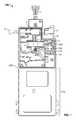
- FIG. 6is a plan view of the device with the locking compartment and electronic compartment exposed.
- FIG. 7is a plan view of the device in a closed and locked configuration.
- FIG. 8is a top view of the device.
- FIG. 9is a plan view of the device having the internal portions exposed and the locking shaft cut and removed.
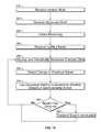
- FIG. 10is a flow diagram of steps performed by the device.
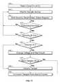
- FIG. 11is a flow diagram of a debounce method.
- FIGS. 12 and 15show a circuit board mounting mechanism.
- FIG. 13shows a grommet
- FIG. 14shows a washer
- FIG. 16is a perspective view of the horizontal shaft within a hasp on a container.
- FIGS. 17-18are side views of hybrid vertical shafts.
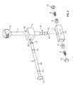
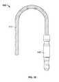
- FIG. 19is a side view of a cable device.
- FIG. 20is a plan view of the device in a closed and locked configuration using the cable.
- FIG. 21is a side view of the device in a closed and locked configuration using the cable.
- FIG. 22is a side view of a horizontal shaft.
- FIG. 23is a side view of a horizontal shaft with an indicative seal.
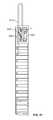
- FIG. 24is side view of a hybrid vertical shaft in a circuit with a contact block.
- FIG. 25is a circuit diagram.
- FIG. 26is a partial plan view of the device having the internal portions exposed in the locking compartment.
- Goodscan be secured, e.g., within a container, using a device that both cannot be opened without the opening being visibly or electronically detected and that is able to track the position of the device when device breach occurs.
- the trackingcan be performed by a global positioning system (GPS).
- GPSglobal positioning system
- One or more authorized entitiescan remotely obtain access to information obtained by the device electronics, such as receiving wireless transmissions from the device. However, the information may only be obtained by the authorized entities, or by unauthorized entities, using a wired communicator when a locking mechanism is released or the system is broken into. Such tampering is visibly and electronically discernible. Locking mechanisms described herein detect each time the device is accessed and thus only allow for authorized persons to obtain, modify or reset the data using a wired communicator without setting off any tampering alerts.
- a device 100 for high security lockingincludes both mechanical and electrical means for ensuring that the device 100 is not opened by others than those authorized to do so.
- a locking compartment 110houses the mechanical and electrical portions of the locking mechanisms. Inside of the locking compartment 110 is a cross block 3 that holds a vertical shaft 1 and a horizontal shaft 2 .
- the vertical shaft 1 and horizontal shaft 2are also referred to as a first shaft and a second shaft, respectively.
- the directions of the shaftsare relative and not determinative, e.g., the two shafts can be perpendicular, but need not have any particular orientation with respect to gravity.
- the vertical shaft 1 and horizontal shaft 2can each be rectilinear, solid, and rigid, that is, not easily bendable by a human without a tool.
- the vertical shaft 1 and horizontal shaft 2both extend from outside of the locking compartment 110 into the interior of the locking compartment 110 .
- the horizontal shaft 2performs the locking function and in some uses extends through apertures, e.g., on a container.
- the horizontal shaft 2is inserted into one or more holes on a lock of a container.
- a large end, e.g., a head, of the horizontal shaft 2 and a housing 225 in which the shaft is lockedprevent the shaft from sliding all the way through holes on the container (see, e.g., FIG. 16 ).
- both ends of the horizontal shaft 2extend outside of the locking compartment 110 . When the locking compartment 110 is closed and the horizontal shaft 2 is in place, the vertical shaft 1 cannot be removed from the device 100 without breaking some component of the device.
- the vertical shaft 1is part of an electrical circuit, e.g., an electrical loop, that is housed in the locking compartment 110 .
- the vertical shaft 1makes electrical contact with a component of the circuit inside the locking compartment 110 . Once the vertical shaft 1 is moved or the shaft 1 is cut, the electrical connection between the vertical shaft 1 and the component is broken, thereby opening the electrical circuit. The short causes the device to determine that a breach has occurred.
- the cross block 3has two apertures 32 , 36 , which each extend all the way through the cross block 3 .
- the apertures 32 , 36are each configured to hold the vertical and horizontal shafts 1 , 2 , respectively.
- one or both of the aperturesis a cylindrical aperture, although the apertures can have a different shape to them, such as rectangular, oval, elliptical or a polygonal.
- the two aperturesare open to one another within the cross block 3 .
- the aperturesare open to one another so that the vertical shaft 1 can be placed in the cross block 3 first and the horizontal shaft 2 inserted after the vertical shaft 1 and the vertical shaft does not prevent the horizontal shaft from be placed through the cross block 3 .
- both of the apertures 32 , 36are offset from a center of the cross block 3 .
- the cross block 3can be a rectangular block, although the shape of the block can be any other shape, so long as the block 3 fits into the appropriate location with in the locking compartment 110 .
- the cross block 3can be formed of a durable material, such as a metal, e.g., steel or aluminum, a ceramic or even a plastic.
- FIGS. 2A-2Cone implementation of a cross block 3 is shown.
- FIG. 2Ais a side view of the cross block 3 .
- the horizontal shaft 2rests in a recess 532 .
- FIG. 2Bshows a plan view of the cross block 3 .
- the vertical shaft 1fits into aperture 36 .
- FIG. 2Cshows a perspective view of the cross block 3 .
- the cross block shown in FIG. 2is similar to the cross block in FIG. 2C , however the recess 532 in FIG. 2C is covered to form aperture 32 in FIG. 2 .
- the recess 532intersects aperture 36 at region 510 .
- Region 510is where the horizontal shaft 2 rests in a notch 19 on the vertical shaft 1 , as described further with respect to FIG. 3 .
- the horizontal shaft 2When inserted through the cross block 3 , the horizontal shaft 2 extends through the cross block 3 approximately perpendicular to the vertical shaft 1 .
- the terms vertical and horizontalare used to indicate the relative orientation of the shafts in the figures and are not meant to be limiting.
- the horizontal shaft 2can be formed of any material that is both sturdy, e.g., cannot be broken by a human using bare hands, but easily broken by a human using a tool, such as a bolt cutter.
- the horizontal shaft 2is a bolt.
- the shaftcan be formed of a ceramic, a metal, or other suitable material. Referring back to FIG. 2 , the horizontal shaft 2 has a body 20 . In some implementations, at the end of the body 20 is a head 21 .
- the head 21has a width, diameter or circumference that is greater than a corresponding width, diameter or circumference of the body 20 .
- the horizontal shaft 2has one or more notched sections 23 , 25 .
- the notched sections 23 , 25facilitate the cutting or breaking of the horizontal shaft 2 .
- the notched sections 23 , 25can extend around the entire circumference of the shaft 2 . Although a single notched section may be sufficient, two or more notched sections provide multiple locations for breaking the vertical shaft 2 , for example, if one of the notched sections is not easily accessible to a cutting tool or if the first attempt to cut the shaft at a first notch is unsuccessful.
- a notchis not so far from its respective end of the shaft that the shaft can be positioned such that the notch can intersect with a notch in the vertical shaft (described below) when the horizontal shaft 2 is locked into place.
- the horizontal shaftalso has an end 27 configured to fit into a locking device (see locking barrel 4 in FIG. 1 ).
- the end 27can have circumferential grooves, ridges, bumps or other features that fit into the locking device and prevent the horizontal shaft 2 from being removed from the locking device.
- the end 27is pointed to a sharp or rounded point.
- the horizontal shaft 2 when in the cross block 3keeps the vertical shaft 1 from being removed from the cross block 3 .
- the vertical shaft 1has a notch 19 in which the horizontal shaft 2 rests.
- the notch 19is formed with a shear mitigation angle, such as an angle of between about 15 and 60, or between 12 and 18 degrees, for example, an angle of about 15 degrees from the plane of the body of the shaft 2 .
- the shear mitigation angleprevents the vertical shaft 1 from shearing the horizontal shaft 2 when the device is subjected to impact force such as hammering the device when it is secured onto a container hasp or during testing, such as ISO 17712 compliant impact and tensile tests.
- the depth and shape of the notchwhich is a circular notch, keeps both of the shafts in place within the cross block 3 .
- the horizontal shaft 2is squeezed between the cross block 3 and notch 19 .
- the engagement between the shafts 1 , 2 and the cross block 3increases. Without the shear mitigation angle, the horizontal shaft is simply “cut” by the edges of the notch on the vertical shaft and the vertical shaft can be disengaged and pulled out.
- the notchhas two areas. An inner region of the notch has a circular cross-section along the longitudinal axis of the shaft.
- the shear mitigation anglecan provide sufficient shear mitigation to the shaft that the shaft complies with the ISO 17712 standard.
- the notch 19is sufficiently deep and the horizontal shaft 2 is sized, e.g., is sufficiently small, that a enough of the horizontal shaft 2 can rest in the notch 19 and prevent the vertical shaft 1 from being pulled out of the cross block 3 once the horizontal shaft 2 is in place.
- the vertical shaft 1can have a diameter along most of its body that is between about 8 and 12 mm, such as between 8.5 and 11 mm, for example, about 10.5 mm.
- the vertical shaft 1has a head 12 .
- the head 12is the portion of the vertical shaft 1 that extends outside of the locking compartment 110 .
- the head 12has a greater width, circumference and/or diameter than the main body of the shaft 1 , which prevents the device 100 from falling out of position when locked onto a container.
- An insulated wire 18extends through the vertical shaft 1 .
- the insulated wire 18is connected in the head to the exterior of the shaft, such as through a conductive bridge 14 .
- the conductive bridge 14is formed of a conductive material, such as a metal, for example copper or brass. The insulation prevents the conductive wire from being in electrical contact with an external surface of the shaft 2 along the length of the wire.
- the exterior of the shaft, the conductive bridge and the insulated wireform a conductive path.
- an insulated portion 13that extends around the circumference of the vertical shaft 1 .
- the insulated portion 13is formed of an insulating material, such as a insulated fiber board or rubber.
- the insulated portion 13extends all the way through to the insulation of the conductive wire or to the wire.
- the wire 18is in conductive contact with a conductive end 22 of the shaft 1 that is on the other side of the insulated portion 13 from the head 12 and abuts the insulated portion 13 (see FIG. 2 ).
- the vertical shaft 1houses an open loop wire that forms a partial circuit, rather than the single insulated wire 18 , conductive bridge and exterior of the shaft forming a partial circuit.
- the vertical shaft 1can be solid and free of any gaps or hollow interior spaces.
- a notched segment 15between the insulated portion 13 and the head is a notched segment 15 .
- the notched segment 15sits within an indicative locking mechanism body 7 .
- At least two locking mechanism inserts 8are held against the vertical shaft 1 , such as within the notched segment 15 , by an indicative locking mechanism spring 9 and an indicative locking mechanism stopper 10 .
- the spring 9is between the insert 8 and the stopper 10 and holds the insert 8 tightly against the vertical shaft 1 .
- the locking mechanism body 7 , springs 9 , inserts 8 and stoppers 10hold the vertical shaft 1 in position, i.e., in electrical contact with the circuit, so that the housing 225 must be pulled off of the vertical shaft 1 with some measure of force.
- the spring tensionis sufficient to hold the vertical shaft 1 in place, but not so high that a user has difficulty in removing the shaft 1 from the housing 225 .
- the inserts 8are electrically conductive and can provide a connection to ground through an exterior of the vertical shaft 1 , exterior of the device and the container on which the device is located. The inserts 8 are in horizontal opposed alignment. Should vibration occur, which could momentary disconnect the vertical shaft, once the inserts are in place, the opposing inserts provide added compression and enhance electrical contact. This maintains the closed electrical loop and prevents any false tamper signals, as described below.
- the locking mechanism body 7has an aperture 37 for connecting to the circuit.
- the locking insertshave apertures for connecting to the circuit.
- the tip of the vertical shaft 1that is the end that is opposite from the head 12 , exposes the conductive wire that extends through the center of the shaft.
- the tipis a conductive piece electrically connected to the conductive wire.
- the end of vertical shaft 1is constructed similar to a TS connector.
- the tip of the vertical shaft 1is in electrical contact with a spring 11 .
- the spring 11provides shock absorption.
- the spring 11maintains the contact between the wire in the shaft 1 and the rest of the circuit.
- the horizontal shaft 2is locked into place by locking barrel 4 .
- the locking barrel 4is constructed so that it can be placed onto the end of the horizontal shaft 2 and stays in place even when a modest amount of pressure is applied to pull the locking barrel 4 away from the shaft 2 . However, if the locking barrel 4 is pulled away from the shaft 2 sufficiently hard, the components within the barrel 4 that grip the shaft break. Once broken, the locking barrel cannot hold itself on the shaft without, e.g., an adhesive. In some implementations, the internal components that grip the shaft 2 are brittle or frangible. In some implementations, a jaw lock type device inside the locking barrel 4 prevents the barrel from being pulled off the shaft once attached.
- the shaft 1when the vertical shaft 1 is in the device, the shaft 1 extends through an aperture 61 in an interlocking cover 6 .
- the deviceis formed so that the interlocking cover 6 , when not locked in place by the vertical shaft 1 , is moveable, such as slidably moveable, between an open and a closed configuration.
- the aperture in the interlocking cover 6is only large enough for the vertical shaft 1 to fit therethrough, i.e., the vertical shaft can fit through the aperture 61 to prevent horizontal movement of the cover 6 .
- the apertureis sufficiently small to prevent opening a chamber 114 that is covered by the cover 6 when the vertical shaft 1 is in place.
- the vertical shaft 1can only be inserted when the cover 6 is either not in the device or when the cover 6 is in a closed position.
- the locking barrel 4is positioned over the cover 6 and is sufficiently large enough to prevent access to the chamber 114 by breaching the cover 6 , such as by drilling through the cover.
- the cover 6can seal with the housing 225 of the device so that water cannot enter the chamber 114 covered by the cover 6 .
- the cover 6when closed covers the chamber 114 holding a connector 150 , which enables a user to physically connect to the device to download, upload or reset information.
- the connector 150can provide power access to the device as well as input and output access.
- the connector 150can be a waterproof connector, such as a 6 pin waterproof connector.
- a dust cover 140can be on the end of the connector 150 .
- a battery within the devicecan also be charged through the connector 150 .
- the batterycan be located, for example, in the electronics compartment 210 .
- the connector 150can be connected to ground, e.g., through the indicative locking mechanism body 7 .
- the electronics compartment 210can also house a circuit board 220 , such as a PCB.
- the PCBcan support a number of chips, including memory, a transmitter, a processor and a GPS device.
- the PCBcan be electrically connected to the connector 150 , ground, e.g., through indicative locking mechanism body 7 , and a switch 5 , described further below.
- the connection to the indicative locking mechanism body 7can be by a wire harness receptacle attached to the body with a contact screw. Because the PCB tends to be sensitive to vibration or jolts, a shock absorptive material can be placed between the circuit board 220 and the housing 225 .
- the PCBis mounted in a chamber on mounting posts.
- the absorptive materialcan be formed of a compliant material such as a rubber.
- a rubber grommet 501can cover a mounting post 502 and extend upwards through a mounting hole in the PCB.
- the grommet 501is a radially symmetric component with a T-shaped cross-section and an aperture 503 though it's axis of symmetry.
- a washer 506is an o-shaped ring. The washer 506 can sit on top of the PCB to cushion it from the top cover of the housing.
- the PCBis insulated from any direct vibration of the housing by a compliant material, such as rubber or PORON, which provides a high compression ratio.
- the washercan fit over the smaller section of the grommet and over a portion of the PCB.
- a side of the washer opposite to the PCBcan provide shock absorbing between the device cover and the PCB.
- a small section of the washerprovides horizontal shock absorbing to the PCB.
- the larger portion of the grommetprovides vertical shock absorbing to the bottom side of the PCB.
- the washeris formed of a high compression ratio material, the washer provides shock absorbing to the top surface of the PCB as well as absorbs any compression force on the cover, mitigating the transfer of force to the PCB. A total of four such mounting posts can be used.
- the shock absorbing materialseals the electronics compartment 210 off form the locking compartment 110 .
- wires extending from the locking compartment 110 into the electronics compartment 210are electrically connected to the circuit board 220 and extend through the shock absorbing material. This prevents any moisture that might enter the locking compartment 110 from entering the electronics compartment 210 and affecting the electronics.
- a separate washer or adhesivesuch as of a waterproof silicon material, seals the space between the wires and the aperture in the electronics compartment 210 that the wires lead through.
- the device 100is likely to be exposed to the elements, e.g., rain, snow, and high humidity from being at sea, and because the locking compartment 110 is not sealed off from the environment, water is likely to collect inside a chamber 114 of the locking compartment 110 at some point. Water can enter the chamber down the sides of vertical shaft 1 . Baffles 116 within the chamber 114 can direct water toward a bottom of the chamber 114 . The water can then exit out drainage apertures 124 leading to the outside of the device 100 .
- the device 100is generally in the upright position shown in FIG. 1 when in use.
- the baffles 116each have at least a downward sloping section 118 in addition to a generally horizontal portion 122 .
- the generally horizontal portion 122can be partially downward sloping, as well.
- baffles 116partially surround the one or more drainage apertures 124 .
- the baffles 116 surrounding the drainage apertures 124can prevent water from entering the device through the apertures.
- the baffles 116can also prevent the device being tampered with through the drainage apertures 124 .
- one or more of the baffles 116can extend most of the way around the drainage apertures 124 , such as at least 80% of the way, such as at least 90% of the way or so that water can move between the gap between the baffle and the housing, but an intruding device, such as a wire, cannot.
- the bafflesextend from an interior of a front wall 130 of the device (front wall shown in FIG. 7 ) to a back wall 132 of the device.
- a switch 5such as a micro switch, is part of the electrical circuit.
- the switchin some implementations is environmentally sealed. Insertion of the horizontal shaft 2 into the device 10 activates an actuator 52 of the switch 5 , closing the circuit. The activation of the actuator 52 is caused by the friction of the shaft 2 along the switch 5 . Removal of the horizontal shaft 2 deactivates the actuator 52 , opening the circuit.
- the switch 5can be connected to both the circuit board 220 , the locking body mechanism 7 , e.g., for ground, and to the internal wire of the vertical shaft 1 , e.g., through spring 11 .
- the housing 225 that forms the electronics compartment 210 and locking compartment 110cannot be opened, other than through the apertures where the shafts are inserted, the cover 6 or by destroying the integrity of the housing 225 .
- the housingis formed from more than one piece, the pieces being bonded together, such as by welding or with an epoxy, e.g., a water resistant epoxy.
- the housingis free of mechanical fasteners, such as screws, which might otherwise hold the pieces of the housing together to form the unit.
- the housing 225can be formed of a rigid material, such as a metal.
- the housing 225can protect the internal electronics (in an electronics compartment 210 ) from solids, such as dust. In some implementations, the housing 225 totally protects the internal electronics, e.g., the electronics with in the electronics chamber 210 from dust. The housing 225 can also protect the electronics from water, such as from low pressure jets of water or even against the effect of immersion of the device in water that is between 15 cm and 1 meter deep. In some implementations, the housing 225 includes an IP67 electronics chamber. The housing can have internal posts that maintain the structural integrity of the device. The posts, any welding and the housing in general can be MIL 810F compliant.
- the devicecan be impervious to environment shock, e.g., various weather conditions, fungus, salt, fog, sand, dust, acceleration, vibration and other potentially damaging circumstances.
- environment shocke.g., various weather conditions, fungus, salt, fog, sand, dust, acceleration, vibration and other potentially damaging circumstances.
- the exterior of the devicecan also include indicator lights, such as green, yellow or red LEDs that indicate a status of the device, such as a battery status, an in-use status or an open circuit status.
- a top view of the deviceshows a cover 90 , which fits around an extending piece on a container.
- Cover 90protects the vertical shaft, covering the exposed potion of the vertical shaft when the vertical shaft is secured onto a container.
- the cover 90can prevent a user from cutting the vertical shaft.
- the horizontal shaft 2when the horizontal shaft 2 is broken, such as at one of the notches 23 , the horizontal shaft 2 can be removed, opening the circuit at switch 5 . This allows for removal of the horizontal shaft 2 from the housing 225 .
- the vertical shaft 1is shown inserted into an aperture of a hasp 1500 of a container door 1510 .
- the aperture of the hasp 1500is sufficiently large to accommodate the shaft of the vertical shaft 1 .
- One potential problem with the hasp 1500 on the container dooris that the apertures in the two parts of the hasp do not always align well with one another. Lack of alignment can make it difficult to place a vertical shaft that is unbendable or entirely rigid through the two apertures.
- the hasp aperturescan also be misshapen from use over time. The hasp apertures can be too small for the vertical shaft to fit into or too thick for the shaft to seat properly in.
- Another potential problemis when the apertures in the hasp cause the vertical shaft to sit at an angle that makes attaching the rest of the device, e.g., the locking compartment, difficult or impossible.
- the locking compartmentmay not fit between the shaft and the container.
- some component of the container or haspprotrudes in such as way that makes putting the shaft through the hasp apertures difficult to impossible.
- a hybrid version of the vertical shaftincludes both rigid and flexible portions.
- the shaft body 530is connected to head 12 .
- the shaft body 530includes an upper rigid portion 535 that is directly contacting head 12 , a lower rigid portion 545 , which includes the notch 19 , and a flexible portion 550 between the upper rigid portion 535 and the lower rigid portion 545 .
- the diameter of the upper and lower rigid portionsis between about 8 and 12 mm, such as between 8.5 and 11 mm, for example, about 10.5 mm.
- the upper rigid portioncan be between 25 and 50 mm long, such as 25, 30, 35, or 43 mm long.
- the lower rigid portionis at least 70 mm long, such as about 75, 80 or 85 mm long.
- the flexible portion 550can be between 10 and 35 mm long, such as 15, 20, 25, or 30 mm long.
- the overall length of the shaftcan be less than about 175 mm long.
- the vertical shaft 1has the flexible portion 550 directly adjacent to the head 12 .
- the flexible portion 550connects to a rigid, but compliant portion 560 , which connects to the lower rigid portion 545 .
- the head 12 of the shaft 1is formed of an insulating material.
- the rigid but compliant portionis an insulating material.
- the flexible portionis formed of a wire rope, such as a steel rope.
- the vertical shafts having a flexible portioninclude an electrically conductive circuit.
- the circuitextends from the end of the shaft, through the lower rigid portion, through the flexible portion and into the head.
- the flexible portionis fabricated with an insulated core.
- One or more conductive wiresrun through a center of the insulated core. For example, one or two wires can form a loop within the head of the shaft.
- One of the wires or one end of a single wireis then conductively connected to the insulated wire in the lower rigid portion, which is then electrically connected to the end or tip of the shaft 1 .
- the other wireis conductively connected to the outer portion of the lower rigid portion.
- the two wires or wire portions in the flexible portioncontinue through the rigid, but compliant material.
- a flexible cable 600is used instead of an entirely rigid vertical shaft 1 .
- the cableincludes the lower rigid portion 545 (also just referred to as a shaft), similar to the hybrid implementations of the vertical shaft described above.
- a flexible portion 610is attached either directly to the lower rigid portion 545 or to a rigid, but compliant material, which is connected to the lower rigid portion 545 .
- the flexible portion 610has an insulated conductive core, such as with one or two conductive wires through the center of the flexible portion 610 . In instances with two conductive wires, a loop or conductive connector connects the two wires at an end of the flexible portion 610 that is opposite to the lower rigid portion 545 .
- the cable 600can be made as short or as long as desired.
- a long cablecan be used where the cable is wrapped around a container.
- a shorter cablecan be used to secure locking bars on a container or in any other situation where a shaft style shaft may not fit or be suitable to secure two parts of a container together.
- the cable 600can be used with a version of the housing 225 ′.
- the housing 225 ′is similar to the housing 225 described with respect to the rigid or hybrid vertical shaft 1 , but has an additional aperture for containing the end of the cable 600 .
- the lower rigid portion 545 of the cablefits into the housing 225 ′ in a similar manner as the rigid or hybrid vertical shaft.
- a part of the flexible portion 610extends out of the housing 225 ′ and back into the device body 101 ′ when locked into the device housing 225 ′.
- an end 620 of the cable opposite to the lower rigid portion 545extends out of the housing 225 ′.
- the extending endindicates that the cable is inserted sufficiently far into the device that it is locked into place. Also, because the end extending out of the device can pulled just a little ways out of the device or further out of the device, the length of cable that forms loop 630 is adjustable.
- an inverse incline mechanismsecures the cable in place once the horizontal shaft 2 is inserted into the device body 101 ′.
- the inverse incline mechanismincludes multiple components that work together, including a vertical bar 640 , a horizontal bar 645 and a spring activated incliner 650 .
- the horizontal shaft 2presses on the vertical bar 640 .
- the vertical bar 640in turn presses on horizontal bar 645 .
- the spring activated incliner 650tilts into a position that holds tight against the flexible portion 610 of the cable.
- the spring activated incliner 650is released and tilts into a position that allows the cable to be released from the device body 101 ′.
- the flexible portion 610 within the housing 225 ′is at the same electrical potential as housing 225 ′, even when an electrical potential is applied to the rigid portion of the cable or the wire within the cable.
- the inverse incline mechanismis connected to the electrical circuitry so that when the flexible portion 610 of the cable is removed from the housing 225 ′, such as by force, the inverse incline mechanism indicates a breach in the device. The breach is subsequently logged into the system.
- the horizontal shaft 2has an aperture 575 for accepting an indicative security device.
- the aperture 575extends through the horizontal shaft 2 , such as perpendicular to a main axis of the shaft.
- the aperture 575is placed between a notch 25 , e.g. the notch that is closest to the end 27 of the shaft 2 if the shaft includes multiple notches, and the end 27 of the shaft 2 .
- the aperture 575can be sized to accept a standard commercial indicative seal, such as a plastic seal.
- the indicative sealcan take the place of the locking barrel 4 , shown in FIG. 1 .
- an indicative seal 580when placed through the aperture 575 and closed locks the horizontal shaft in place. That is, assuming the shaft is inserted through the cross block 3 (as shown in FIG. 1 ), the indicative seal 580 prevents the horizontal shaft 2 from being pulled out of the cross block 3 , because the plastic seal 580 cannot fit through the aperture in the locking compartment 110 . Thus, the horizontal shaft 2 with the indicative seal 580 locks the vertical shaft in place. When the vertical shaft 1 is on a container, such as through apertures in a hasp, the horizontal shaft 2 with the indicative seal 580 locks the hasp on the container. This indicative seal 580 can be removed easier and faster by the authorized party to the transaction, than cutting the metal barrier horizontal shaft. However, the indicative seal 580 may not be in compliance with some industry standards and therefore may not be used in all instances. The horizontal shaft 2 cannot be removed without either breaking or breaching the indicative seal or breaking the horizontal shaft.
- the indicative seal 580can provide an even lower consumable part cost than the horizontal shaft 2 .
- the indicative sealincludes an identification or serial number. If tampered or removed by an unauthorized party, the lack of a seal or a seal without the correct identification or serial number can provide a visual indication of tampering, in addition to any electronically received indication of tampering.
- a vertical shaft 1is shown held by a cross block 3 against a second shaft 2 , which passes through a contact block 714 .
- An electrical pathis provided from a terminal 710 on the bottom of the contact block 714 .
- electrically conductive materialcontacts the exterior 2 of the second shaft.
- the contact block 714can either be formed entirely of the electrically conductive material or can include a portion that is formed entirely of the electrically conductive material.
- an electrically conductive plunger 725contacts the exterior of the horizontal shaft 2 .
- the optional conductive plunger 725 and portion of the horizontal shaft 2 that are within the contact block 714are indicated in phantom in the figure.
- the electrically conductive horizontal shaft 2contacts the electrically conductive exterior 702 of the vertical shaft 1 .
- the hybrid vertical shaft(see FIG. 17 ) is shown in FIG. 24
- the solid or non-flexible vertical shaft 1as shown in FIG. 2
- the vertical shaft 1provides an electrical path from the exterior 702 through to the conductive end 22 of the shaft.
- FIG. 25shows the equivalent circuit with the vertical shaft 1 and horizontal shaft 2 acting as switches to close the circuit for a secure seal or to open the circuit for a tampered seal.
- the contact block 714may provide higher reliability than a switch component, e.g., as shown in FIG. 1 , to sense the presence of the horizontal shaft 2 . In some implementations there are stabilization plungers in the contact block 714 to securely hold in place the horizontal shaft 2 .
- FIG. 26shows a possible implementation with the electrical circuit brought down with wires to a connector 730 for monitoring by a circuit board.
- the devicecan be used to secure a container to be shipped using the following method.
- a device that is ready for usehas the vertical and horizontal shafts removed.
- a userinserts the vertical shaft through the locking mechanism or aperture of the container.
- the vertical shaftis then received by the device (step 310 ). Inserting the vertical shaft closes part of the circuit connected the circuit board.
- the sliding coveris in the closed position, that is, the connector is covered when the vertical shaft is inserted.
- the covercannot be moved to the open position.
- the locking mechanism body, springs and insertsenable the automatic alignment of the vertical shaft to the cross block, the user need not hold the device in place once the vertical shaft is inserted. The user therefore has his or her hands free to insert the horizontal shaft.
- the userinserts the horizontal shaft, which is received into the housing (step 320 ). Inserting the horizontal shaft locks the vertical shaft in place. Inserting the horizontal shaft also closes the micro switch, which closes the circuit. Alternatively, two or more separate circuits can be connected to the circuit board and logic can activate only if both are closed. Once the horizontal shaft is in place, the circuit is closed and the monitoring is initiated (step 330 ). The user then locks the locking barrel onto the end of the horizontal shaft, thus, the horizontal shaft receives the locking barrel (step 340 ).
- the deviceis now ready to track the container and send messages to a receiver regarding the integrity of the device along with location information.
- the devicecan monitor and optionally send data packets on a periodic basis (step 350 ).
- the devicedetermines that periodic monitoring is not necessary when a receiver or transmitter is not within range.
- status informationcan be sent, such as one every hour, once every 20 minutes or more frequently, such as once every 5 minutes.
- the datacan be sent, e.g., using a network, such as a GSM, 2G or 3G network.
- the devicecan also receive messages wirelessly.
- the devicecan continuously monitor security regardless of whether it is in range of communications or not. Event, GPS location and other data can be stored in memory for later retrieval. If a breach is detected when out of range of communications, the breach information is stored and is reported when the device comes into range of communications.
- the electrical signal through the circuitcan change during monitoring. This change in electrical signal is detected (step 360 ).
- the change in electric signalcan be caused by an environmental shock or by a breach.
- An environmental shockcan be any hard bounce or hit taken by the device that temporarily causes a short in the circuit, e.g., when the spring loses contact with the conductive portion of the shaft.
- a breachcan occur when someone opens the device, either by removing one of the shafts or by cutting the vertical shaft, thereby opening the conductive loop of the circuit.
- the devicecan initiate a debouncing method to determine whether the change in electrical signal is a breach or a temporary short or opening caused by an environmental shock (step 370 ).
- the debouncing methoddetermines when the short is for such an insignificant length of time that an actual breach has not occurred. Rather, the contacts were merely jiggled out of place for a moment.
- the systemcan check to determine whether a breach has occurred by changing the electrical signal sent through the circuit.
- an exemplary debounce methodcan occur as follows.
- the secure state of the security circuit, or locked stateis represented by a closed electrical circuit or logic 1
- the non-secure statei.e., an open state or breach
- an open electrical circuit or logic 1Once secured, a change from secure to non-secure causes an interrupt to a microprocessor, and an open circuit is detected (step 400 ).
- the security state of 0is shifted into a status register, the number of debouncing samples needed is set to the sample length and a debouncing loop is entered.
- a waitis performed for the sample interval (step 401 ). After the wait, the state of the circuit is sampled, shifted as a bit into the sample register (step 402 ), then the number of samples taken are tested against the sample length to determine whether the samples are completed (step 403 ). If insufficient samples have been taken, then the sampling loop is repeated (step 401 ). When sufficient samples have been taken, the sample register is tested to determine whether the samples are all 1's or 0's, (step 404 ). If the sample register has not settled to a state of all 1's or all 0's, then the sampling loop (step 401 ) is repeated to take an additional sample, then retested for a settled state of all 1's or all 0's (step 404 ).
- the registeris tested for all 1's, meaning secure (step 405 ). If the settled sample register is not all 1's, e.g., all 0's, then a tamper is declared (step 408 ).
- the voltage through the security circuitis changed (step 406 ) for the purpose of testing for a splice attempt.
- the continuity of the security circuitis tested (step 407 ), with a secure status indicating that a tamper false alarm has been detected (step 409 ).
- a counter of tamper false alarmscan be incremented. If the security circuit continuity check following the voltage change fails, then a tamper attempt using a splice has been detected. A tamper is declared (step 408 ).
- the devicetransmits data regarding the breach, such as the occurrence itself, the time of the occurrence and the location, to a data collector (step 390 ).
- the location and tamper timecan also be recorded in the device, such as for later download.
- the data regarding the breachis immediately transmitted. “Immediately” may mean within 2 minutes, such as within 30 seconds.
- the breach datais transmitted once the device is within range of a receiver capable of receiving the data.
- an external signal on the deviceis changed to indicate the tamper. For example, a light, such as a red LED light may be lit.
- a receiver or an authoritycan use the device to determine whether the container has been tampered with or breached.
- a first inspectionis a visual inspection of the exterior of the device. The inspector will easily be able to determine whether the security status has detected a breach by observing the state of the LED indicators. The inspector can in addition determine if the device itself has been tampered with by observing whether the device has been drilled into, cut, or otherwise opened. As there are no user accessible screws or opening mechanisms, access to the internals of the device leaves an indication of such tampering.
- the horizontal shaftmay be cut and the horizontal and vertical shafts removed to remove the device for reuse.
- the vertical shaftis reusable and the horizontal shaft and locking barrel are inexpensive consumable parts which can be replaced when the device is put back into service.
Landscapes
- Engineering & Computer Science (AREA)
- Physics & Mathematics (AREA)
- General Physics & Mathematics (AREA)
- Computer Security & Cryptography (AREA)
- Theoretical Computer Science (AREA)
- Casings For Electric Apparatus (AREA)
- Burglar Alarm Systems (AREA)
- Details Of Rigid Or Semi-Rigid Containers (AREA)
- Lock And Its Accessories (AREA)
Abstract
Description
Claims (57)
Priority Applications (1)
| Application Number | Priority Date | Filing Date | Title |
|---|---|---|---|
| US12/836,209US8593280B2 (en) | 2009-07-14 | 2010-07-14 | Security seal |
Applications Claiming Priority (3)
| Application Number | Priority Date | Filing Date | Title |
|---|---|---|---|
| US22550809P | 2009-07-14 | 2009-07-14 | |
| US26379409P | 2009-11-23 | 2009-11-23 | |
| US12/836,209US8593280B2 (en) | 2009-07-14 | 2010-07-14 | Security seal |
Publications (2)
| Publication Number | Publication Date |
|---|---|
| US20110133932A1 US20110133932A1 (en) | 2011-06-09 |
| US8593280B2true US8593280B2 (en) | 2013-11-26 |
Family
ID=43449766
Family Applications (1)
| Application Number | Title | Priority Date | Filing Date |
|---|---|---|---|
| US12/836,209Active2031-12-10US8593280B2 (en) | 2009-07-14 | 2010-07-14 | Security seal |
Country Status (7)
| Country | Link |
|---|---|
| US (1) | US8593280B2 (en) |
| EP (1) | EP2454729A1 (en) |
| KR (1) | KR20120126059A (en) |
| CN (1) | CN103548071B (en) |
| IL (1) | IL217532A0 (en) |
| MY (1) | MY153581A (en) |
| WO (1) | WO2011008871A1 (en) |
Cited By (3)
| Publication number | Priority date | Publication date | Assignee | Title |
|---|---|---|---|---|
| US9142107B2 (en) | 2009-07-14 | 2015-09-22 | Deal Magic Inc. | Wireless tracking and monitoring electronic seal |
| US9177282B2 (en) | 2009-08-17 | 2015-11-03 | Deal Magic Inc. | Contextually aware monitoring of assets |
| US10354502B2 (en)* | 2015-12-07 | 2019-07-16 | For-U Technics Co., Ltd. | Container door electronic seal system |
Families Citing this family (14)
| Publication number | Priority date | Publication date | Assignee | Title |
|---|---|---|---|---|
| US8432274B2 (en) | 2009-07-31 | 2013-04-30 | Deal Magic, Inc. | Contextual based determination of accuracy of position fixes |
| US8314704B2 (en) | 2009-08-28 | 2012-11-20 | Deal Magic, Inc. | Asset tracking using alternative sources of position fix data |
| US8334773B2 (en) | 2009-08-28 | 2012-12-18 | Deal Magic, Inc. | Asset monitoring and tracking system |
| JP5088427B2 (en)* | 2011-03-02 | 2012-12-05 | 第一精工株式会社 | Electrical connector and electrical connector assembly |
| US8487768B2 (en)* | 2011-08-30 | 2013-07-16 | Chung-Shan Institute Of Science And Technology, Armaments Bureau, Ministry Of National Defense | Electronic seal equipped with a breakage-detecting circuit and method for sealing a door based on the same |
| US20140091781A1 (en)* | 2012-09-28 | 2014-04-03 | Hutchison International Ports Enterprises Limited | Security system |
| WO2014053551A1 (en)* | 2012-10-03 | 2014-04-10 | Oneseal Aps | Engagement lock for a container |
| EP2717242A1 (en)* | 2012-10-03 | 2014-04-09 | Oneseal A/S | Engagement lock for a container |
| CN102930779B (en)* | 2012-11-06 | 2018-04-06 | 群淂数码科技(上海)有限公司 | Disposable block electronic tag |
| US9423418B2 (en)* | 2013-02-25 | 2016-08-23 | Google Technology Holdings LLC | Capacitive sensor |
| US11775892B2 (en) | 2013-10-03 | 2023-10-03 | Crc R&D, Llc | Apparatus and method for freight delivery and pick-up |
| US10019878B2 (en)* | 2014-10-15 | 2018-07-10 | Cross Road Centers, Llc | Method, apparatus and systems for tracking freight |
| CN104992622A (en)* | 2015-07-21 | 2015-10-21 | 河南江雁电气有限公司 | Electronic seal |
| WO2019139862A1 (en)* | 2018-01-09 | 2019-07-18 | University Of Louisville Research Foundation, Inc. | Semiconducting materials with surrounding radial p-n diodes |
Citations (263)
| Publication number | Priority date | Publication date | Assignee | Title |
|---|---|---|---|---|
| US690191A (en) | 1901-08-14 | 1901-12-31 | John G Saxe | Lock. |
| US3688256A (en) | 1971-04-28 | 1972-08-29 | Threshold Eng Inc | Vehicle intrusion alarm system |
| US3848243A (en) | 1973-02-09 | 1974-11-12 | H Schirmer | Inductive reactance proximity alarm system for bulky movable objects |
| US3961323A (en) | 1971-02-22 | 1976-06-01 | American Multi-Lert Corporation | Cargo monitor apparatus and method |
| US3993987A (en) | 1975-03-03 | 1976-11-23 | Stevens Edward C | Locking device having an integral alarm system |
| US4118057A (en) | 1978-02-24 | 1978-10-03 | The United States Of America As Represented By The United States Department Of Energy | Reusable, tamper-indicating seal |
| US4233595A (en) | 1978-11-30 | 1980-11-11 | Christoph Emmerich Kg | Chain-type door latch and alarm |
| US4262284A (en) | 1978-06-26 | 1981-04-14 | Stieff Lorin R | Self-monitoring seal |
| US4300057A (en) | 1978-07-04 | 1981-11-10 | Hiperblock, S.A. | Anti-theft apparatus for vehicles |
| US4523186A (en) | 1982-08-12 | 1985-06-11 | The United States Of America As Represented By The United States Department Of Energy | Seal system with integral detector |
| US4556872A (en) | 1983-08-18 | 1985-12-03 | John F. Masoncup | Padlock with tamper alarm |
| US4627248A (en) | 1985-09-23 | 1986-12-09 | Sentry Lock Co., Inc. | Trailer door lock system |
| US4699408A (en) | 1985-09-06 | 1987-10-13 | Kesselman David A | Tamper deterrent assembly |
| US4729626A (en) | 1982-07-15 | 1988-03-08 | The Fiber-Lock Corporation | Self-locking fiber optic seal |
| US4736857A (en) | 1986-11-14 | 1988-04-12 | American Home Products Corporation | Tamper indicating closure |
| US4768816A (en) | 1983-04-14 | 1988-09-06 | Miner Enterprises Inc. | Means for sealing or locking a cam action door fastener |
| US4802700A (en) | 1987-11-09 | 1989-02-07 | Trans-Guard Industries, Inc. | Locking seal |
| US4811977A (en) | 1988-04-18 | 1989-03-14 | E. J. Brooks Company | Labeled security seal |
| US4816822A (en) | 1986-02-14 | 1989-03-28 | Ryan Instruments, Inc. | Remote environmental monitor system |
| US4924210A (en) | 1987-03-17 | 1990-05-08 | Omron Tateisi Electronics Company | Method of controlling communication in an ID system |
| US4946210A (en) | 1988-06-20 | 1990-08-07 | Stoffel Seals Corporation | Tamper resistant shackle seal |
| US4990890A (en) | 1988-05-02 | 1991-02-05 | Newby Lionel L | Vehicle security system |
| US4992789A (en) | 1989-10-31 | 1991-02-12 | Daniel Czerwinski | Marine lock and alarm apparatus |
| US5005883A (en) | 1990-05-24 | 1991-04-09 | E. J. Brooks Company | Tamper indicator for a locking seal |
| US5021610A (en) | 1990-01-04 | 1991-06-04 | Square D Company | Strain relief connection |
| US5099228A (en) | 1989-02-09 | 1992-03-24 | Marcia Israel | Electronic anti-theft merchandise tag having means for activating an alarm in response to an attempt to remove the tag from the merchandise |
| US5103207A (en) | 1989-10-20 | 1992-04-07 | Hitek-Protek Systems Incorporated | Taut wire sensing apparatus |
| US5120097A (en) | 1990-07-30 | 1992-06-09 | The Rel Corporation | Security seal |
| US5126746A (en) | 1991-07-08 | 1992-06-30 | The United States Of America As Represented By The United States Department Of Energy | Secure distance ranging by electronic means |
| US5151684A (en) | 1991-04-12 | 1992-09-29 | Johnsen Edward L | Electronic inventory label and security apparatus |
| US5189396A (en) | 1990-06-16 | 1993-02-23 | Anatoli Stobbe | Electronic seal |
| US5247564A (en) | 1990-10-24 | 1993-09-21 | Gte Mobile Communications Service Corp. | Adaptive vehicle alarm detection and reporting system |
| US5258741A (en) | 1990-05-18 | 1993-11-02 | Innovision Technologies Group, Inc. | Portable anti-theft alarm and locking device for vehicles |
| US5266925A (en) | 1991-09-30 | 1993-11-30 | Westinghouse Electric Corp. | Electronic identification tag interrogation method |
| US5284036A (en) | 1992-12-02 | 1994-02-08 | Rosenbaum Nathan B | Tamper-resistant security lock for cargo container doors |
| US5298884A (en) | 1992-10-16 | 1994-03-29 | Bi Incorporated | Tamper detection circuit and method for use with wearable transmitter tag |
| US5302954A (en) | 1987-12-04 | 1994-04-12 | Magellan Corporation (Australia) Pty. Ltd. | Identification apparatus and methods |
| US5406263A (en) | 1992-07-27 | 1995-04-11 | Micron Communications, Inc. | Anti-theft method for detecting the unauthorized opening of containers and baggage |
| US5427423A (en) | 1993-09-27 | 1995-06-27 | E. J. Brooks Company | Padlock security seal with internal bar code |
| US5483666A (en) | 1991-10-21 | 1996-01-09 | Matsushita Electric Industrial Co., Ltd. | Method for allocating channels in a microcellular system |
| US5491486A (en) | 1994-04-25 | 1996-02-13 | General Electric Company | Mobile tracking units employing motion sensors for reducing power consumption therein |
| EP0516611B1 (en) | 1991-05-02 | 1996-04-10 | GRUNDMANN SCHLIESSTECHNIK GESELLSCHAFT m.b.H. | Locking cylinder and key |
| US5515030A (en) | 1993-04-09 | 1996-05-07 | Nynex Science & Technology, Inc. | Electronic seal |
| US5525992A (en) | 1994-11-14 | 1996-06-11 | Texas Instruments Deutschland Gmbh | Method and system for conserving power in a recognition system |
| US5541604A (en) | 1993-09-03 | 1996-07-30 | Texas Instruments Deutschland Gmbh | Transponders, Interrogators, systems and methods for elimination of interrogator synchronization requirement |
| US5565858A (en) | 1994-09-14 | 1996-10-15 | Northrop Grumman Corporation | Electronic inventory system for stacked containers |
| US5587702A (en) | 1992-11-12 | 1996-12-24 | Chadfield; Garth R. | Padlock with tamper alarm |
| US5615247A (en) | 1994-10-11 | 1997-03-25 | Mills; Thomas O. | Security device for the protection of cargo transport containers |
| US5656996A (en) | 1996-03-13 | 1997-08-12 | Global Associates, Ltd. | Electronic security bonding device |
| US5727405A (en) | 1997-02-03 | 1998-03-17 | Cromwell; Daryl | Alarm padlock |
| US5752218A (en) | 1995-05-31 | 1998-05-12 | General Electric Company | Reduced-power GPS-based system for tracking multiple objects from a central location |
| US5758263A (en) | 1995-12-07 | 1998-05-26 | Rockwell International Corporation | Selection of communication channel in a digital cordless telephone |
| US5774876A (en) | 1996-06-26 | 1998-06-30 | Par Government Systems Corporation | Managing assets with active electronic tags |
| US5798460A (en) | 1994-06-20 | 1998-08-25 | Sony Corporation | Vibration sensor employing a flexible diaphragm and an electret film |
| US5815407A (en) | 1995-12-14 | 1998-09-29 | Motorola Inc. | Method and device for inhibiting the operation of an electronic device during take-off and landing of an aircraft |
| US5819569A (en) | 1996-08-29 | 1998-10-13 | Herdman; Rodrick A. | Lock with changeable warding positions |
| US5836002A (en) | 1995-06-01 | 1998-11-10 | Morstein; Jason | Anti-theft device |
| US5861810A (en) | 1996-09-27 | 1999-01-19 | Nguyen; Yung T. | System and method for providing crime victims updated information and emergency alert notices |
| US5946350A (en) | 1995-12-27 | 1999-08-31 | Matsushita Electric Industrial Co., Ltd. | Data receiving system using a decision feedback equalizer |
| US5959529A (en) | 1997-03-07 | 1999-09-28 | Kail, Iv; Karl A. | Reprogrammable remote sensor monitoring system |
| US6026690A (en) | 1994-06-20 | 2000-02-22 | Sony Corporation | Vibration sensor using the capacitance between a substrate and a flexible diaphragm |
| US6069563A (en) | 1996-03-05 | 2000-05-30 | Kadner; Steven P. | Seal system |
| US6075443A (en) | 1998-07-31 | 2000-06-13 | Sarnoff Corporation | Wireless tether |
| US6243005B1 (en) | 1998-08-03 | 2001-06-05 | Hi-F-Tek Ltd. | Self-locking seal |
| US6249252B1 (en) | 1996-09-09 | 2001-06-19 | Tracbeam Llc | Wireless location using multiple location estimators |
| US6265973B1 (en) | 1999-04-16 | 2001-07-24 | Transguard Industries, Inc. | Electronic security seal |
| US6292108B1 (en) | 1997-09-04 | 2001-09-18 | The Board Of Trustees Of The Leland Standford Junior University | Modular, wireless damage monitoring system for structures |
| US20010022558A1 (en) | 1996-09-09 | 2001-09-20 | Tracbeam Llc | Wireless location using signal fingerprinting |
| GB2368174A (en) | 2000-10-19 | 2002-04-24 | Encrypta Electronics Ltd | Security seal device with detatchable cable display indicating reopening |
| US6420971B1 (en) | 1999-06-23 | 2002-07-16 | Tripseal Limited | Electronic seal, methods and security system |
| US20020100300A1 (en)* | 2001-01-31 | 2002-08-01 | Rex Reeb | Automobile anti-theft system |
| US20020104013A1 (en) | 2001-02-01 | 2002-08-01 | Ohanes Ghazarian | Electronic vehicle product and personal monitoring |
| US20020111819A1 (en) | 2000-12-07 | 2002-08-15 | Savi Technology, Inc. | Supply chain visibility for real-time tracking of goods |
| US20020113704A1 (en)* | 2000-09-20 | 2002-08-22 | Hess Brian K. | Wireless transmitting security cable |
| US6496766B1 (en) | 1999-03-01 | 2002-12-17 | North Carolina State University | Crane monitoring and data retrieval systems and method |
| US6529131B2 (en) | 2001-06-13 | 2003-03-04 | Robert E. Wentworth | Electronic tether |
| US6571213B1 (en) | 1999-12-30 | 2003-05-27 | Pitney Bowes Inc. | Router utility for a parcel shipping system |
| US20030126024A1 (en) | 2001-12-27 | 2003-07-03 | Manugistics, Inc. | System and method for replenishment by purchase with attribute based planning |
| US20030137968A1 (en) | 2002-01-18 | 2003-07-24 | Lareau Neil William | Monitoring and tracking of assets by utilizing wireless communications |
| US20030146871A1 (en) | 1998-11-24 | 2003-08-07 | Tracbeam Llc | Wireless location using signal direction and time difference of arrival |
| US20030171948A1 (en) | 2002-02-13 | 2003-09-11 | United Parcel Service Of America, Inc. | Global consolidated clearance methods and systems |
| US20030195791A1 (en) | 1999-01-26 | 2003-10-16 | Waller Matthew A. | System, method and article of manufacture to determine and communicate redistributed product demand |
| US20030227392A1 (en) | 2002-01-11 | 2003-12-11 | Ebert Peter S. | Context-aware and real-time item tracking system architecture and scenarios |
| US20030233189A1 (en) | 2002-06-13 | 2003-12-18 | Hsiao Victor K. | Mobile-trailer tracking system and method |
| US6727817B2 (en) | 1998-09-11 | 2004-04-27 | Key-Trak, Inc. | Tamper detection and prevention for an object control and tracking system |
| US6736768B2 (en)* | 2000-11-02 | 2004-05-18 | Gambro Inc | Fluid separation devices, systems and/or methods using a fluid pressure driven and/or balanced approach |
| US20040100379A1 (en) | 2002-09-17 | 2004-05-27 | Hans Boman | Method and system for monitoring containers to maintain the security thereof |
| US20040113783A1 (en) | 2002-12-11 | 2004-06-17 | Millennium Information Systems, Llc | Container integrity management system |
| US20040113933A1 (en) | 2002-10-08 | 2004-06-17 | Northrop Grumman Corporation | Split and merge behavior analysis and understanding using Hidden Markov Models |
| US6753775B2 (en) | 2002-08-27 | 2004-06-22 | Hi-G-Tek Ltd. | Smart container monitoring system |
| US20040124977A1 (en) | 2001-03-06 | 2004-07-01 | Peter Biffar | Rule based proximity and time based tracking system |
| US20040126015A1 (en) | 2002-12-31 | 2004-07-01 | Hadell Per Anders | Container identification and tracking system |
| US6778083B2 (en)* | 2002-08-27 | 2004-08-17 | Hi-G-Tek Ltd. | Electronic locking seal |
| US6792353B2 (en) | 2000-09-26 | 2004-09-14 | American Gnc Corporation | Enhanced inertial measurement unit/global positioning system mapping and navigation process |
| US20040183673A1 (en) | 2003-01-31 | 2004-09-23 | Nageli Hans Peter | Portable detachable self-contained tracking unit for two-way satellite communication with a central server |
| US20040193466A1 (en) | 2003-03-27 | 2004-09-30 | Irena Kull | Method and process for managing a yard |
| US20040199411A1 (en) | 2003-04-04 | 2004-10-07 | Bertram Jeffrey Mark | Method and system for rebooking a passenger |
| US20040198386A1 (en) | 2002-01-16 | 2004-10-07 | Dupray Dennis J. | Applications for a wireless location gateway |
| US20040202154A1 (en) | 2000-08-31 | 2004-10-14 | Neoris Logistics, Inc. | Centralized system and method for optimally routing and tracking articles |
| US20040227630A1 (en) | 2003-04-09 | 2004-11-18 | Shannon David L. | Continuous security state tracking for intermodal containers transported through a global supply chain |
| US20040246130A1 (en) | 2003-04-09 | 2004-12-09 | Lambright Stephen J. | State monitoring of a container |
| US20040257225A1 (en) | 2003-06-17 | 2004-12-23 | Intelagents, Inc. | Global intelligent remote detection system |
| US20040266457A1 (en) | 1997-08-20 | 2004-12-30 | Dupray Dennis J. | Wireless location gateway and applications therefor |
| US20050055237A1 (en) | 2003-09-05 | 2005-03-10 | Sensitech Inc. | Using advanced shipping notification information for supply chain process analysis |
| US6879962B1 (en) | 1998-05-24 | 2005-04-12 | Joseph D. Smith | Logistics system and method |
| US20050091091A1 (en) | 2000-10-10 | 2005-04-28 | Inttra, Inc. | Common carrier system |
| US20050156736A1 (en) | 2003-05-13 | 2005-07-21 | Rajapakse Ravindra U. | Federated system for monitoring physical assets |
| US20050159883A1 (en) | 2004-01-16 | 2005-07-21 | Worldcom, Inc. | Method and system for tracked device location and route adherence via geofencing |
| US6927688B2 (en) | 2003-04-02 | 2005-08-09 | Caci International Inc. | Method for enabling communication and condition monitoring from inside of a sealed shipping container using impulse radio wireless techniques |
| US20050190097A1 (en) | 2004-03-01 | 2005-09-01 | Hsiongwei Hsu | Freight container monitoring system |
| US20050219037A1 (en) | 2004-04-02 | 2005-10-06 | Tao Huang | Cargo theft prevention method and system |
| US20050248454A1 (en) | 2004-05-06 | 2005-11-10 | Hanson Gregory R | Marine asset security and tracking (MAST) system |
| US6965313B1 (en) | 2001-04-24 | 2005-11-15 | Alarm.Com Inc. | System and method for connecting security systems to a wireless device |
| US20050256731A1 (en) | 2004-05-14 | 2005-11-17 | Mougey Vincent J | Methods and systems for postcode-to-postcode delivery interval and routing calculation |
| US6990335B1 (en) | 2004-11-18 | 2006-01-24 | Charles G. Shamoon | Ubiquitous connectivity and control system for remote locations |
| US20060047379A1 (en) | 2004-08-27 | 2006-03-02 | Schullian John M | Railcar transport telematics system |
| US20060054705A1 (en) | 2004-09-08 | 2006-03-16 | Georgia-Pacific Corporation | Package insert with integrated radio frequency transponder |
| US7035856B1 (en) | 2000-09-28 | 2006-04-25 | Nobuyoshi Morimoto | System and method for tracking and routing shipped items |
| US7044374B2 (en) | 2003-08-19 | 2006-05-16 | Southwest Airlines Co. | Mobile data reading system |
| US20060101897A1 (en) | 2004-11-12 | 2006-05-18 | Fanuc Ltd | Impact detection device |
| US7049963B2 (en) | 2003-04-09 | 2006-05-23 | Visible Assets, Inc. | Networked RF tag for tracking freight |
| US20060109109A1 (en) | 2004-11-19 | 2006-05-25 | Savi Technology, Inc. | Method and apparatus involving global positioning and long-range wireless link |
| WO2006053566A1 (en) | 2004-11-22 | 2006-05-26 | A.P. Møller-Mærsk A/S | Shipping container monitoring and tracking system |
| US20060116893A1 (en) | 2004-11-24 | 2006-06-01 | Carnes Joseph L | Apparatus and method of collecting and monitoring shipment data |
| US20060123766A1 (en)* | 2003-08-23 | 2006-06-15 | Saurer Gmbh & Co., Kg | Opening roller assembly for an open-end spinning machine |
| US7072668B2 (en) | 2001-05-22 | 2006-07-04 | Geospatial Technologies, Inc. | Durable global asset-tracking device and a method of using the same |
| US20060145837A1 (en) | 2004-12-17 | 2006-07-06 | United Parcel Of America, Inc. | Item-based monitoring systems and methods |
| US20060155591A1 (en) | 2005-01-10 | 2006-07-13 | Faheem Altaf | Systems, methods, and media for managing a travel itinerary |
| US7098784B2 (en) | 2003-09-03 | 2006-08-29 | System Planning Corporation | System and method for providing container security |
| US20060202824A1 (en) | 2005-02-04 | 2006-09-14 | Container Security Inc. | Electronic seal and method of shipping container tracking |
| US7113090B1 (en) | 2001-04-24 | 2006-09-26 | Alarm.Com Incorporated | System and method for connecting security systems to a wireless device |
| US20060229895A1 (en) | 2005-04-12 | 2006-10-12 | United Parcel Service Of America, Inc. | Next generation visibility package tracking |
| US20060232398A1 (en) | 2005-04-14 | 2006-10-19 | Nedblake Greydon W | System for personal possessions security |
| US20060238332A1 (en) | 2005-02-02 | 2006-10-26 | Carle Patrick F | Wireless integrated condition monitoring system |
| US7136830B1 (en) | 1999-07-20 | 2006-11-14 | World Factory, Inc. | Method of producing, selling, and distributing articles of manufacture through the automated aggregation of orders and the visual representation of standardized shipping volumes |
| US20060276201A1 (en) | 1996-09-09 | 2006-12-07 | Tracbeam Llc | Wireless location routing applications and archectiture therefor |
| US20060288744A1 (en) | 2005-06-28 | 2006-12-28 | William Smith | Alarm lock |
| US20070043538A1 (en) | 2000-06-16 | 2007-02-22 | Johnson Daniel T | Method and system of asset identification and tracking for enterprise asset management |
| US20070046459A1 (en) | 2005-08-31 | 2007-03-01 | Motorola, Inc. | Methods and apparatus for asset tracking |
| US20070056369A1 (en) | 2005-09-15 | 2007-03-15 | Jim Griffin | Apparatus and method for monitoring in-transit shipments |
| US7193557B1 (en) | 2003-04-29 | 2007-03-20 | Lockheed Martin Corporation | Random set-based cluster tracking |
| US7196621B2 (en) | 2002-05-07 | 2007-03-27 | Argo-Tech Corporation | Tracking system and associated method |
| US7212829B1 (en) | 2000-02-28 | 2007-05-01 | Chung Lau | Method and system for providing shipment tracking and notifications |
| US20070120381A1 (en) | 2005-11-15 | 2007-05-31 | Jakob Ehrensvard | Electronic tamper evident seal |
| CN1989513A (en) | 2004-05-24 | 2007-06-27 | 美国邮政服务公司 | Method and system for tracking assets in a transportation network |
| US20070150379A1 (en) | 2005-12-02 | 2007-06-28 | Vernaci Kathryn R | Method and system for real-time monitoring of part availability |
| US20070145130A1 (en) | 2005-12-02 | 2007-06-28 | Asd Specialty Healthcare, Inc. | Method and apparatus for pharmaceutical management and tracking |
| US7239238B2 (en) | 2004-03-30 | 2007-07-03 | E. J. Brooks Company | Electronic security seal |
| US20070182556A1 (en) | 2006-01-31 | 2007-08-09 | Wherenet Corp | System and method for tracking assets within a monitored environment |
| US7274332B1 (en) | 1996-09-09 | 2007-09-25 | Tracbeam Llc | Multiple evaluators for evaluation of a purality of conditions |
| US20070222674A1 (en) | 2006-03-24 | 2007-09-27 | Containertrac, Inc. | Automated asset positioning for location and inventory tracking using multiple positioning techniques |
| US20070222232A1 (en) | 2004-10-28 | 2007-09-27 | Assa Abloy Identification Technology Group Ab | Security sealing device comprising a rfid tag |
| US7275651B2 (en) | 2003-11-06 | 2007-10-02 | Morales Kevin L | Double-skin, low-profile, environmental, safety tank system |
| US20070247366A1 (en) | 2003-10-22 | 2007-10-25 | Smith Derek M | Wireless postion location and tracking system |
| US20070252696A1 (en) | 2006-05-01 | 2007-11-01 | Belisle Timothy F | Geo-location system, method and apparatus |
| US20070262861A1 (en) | 2006-05-15 | 2007-11-15 | Anderson Tommie K | Mobile asset tracking system and method |
| US20070285232A1 (en) | 2005-05-13 | 2007-12-13 | Karl Bohman | Method and system for arming a multi-layered security system |
| US20070287473A1 (en) | 1998-11-24 | 2007-12-13 | Tracbeam Llc | Platform and applications for wireless location and other complex services |
| US7315281B2 (en) | 2004-07-30 | 2008-01-01 | G2 Microsystems Pty. Ltd. | Location determination method and system for asset tracking devices |
| US20080006696A1 (en) | 2006-07-06 | 2008-01-10 | Ricoh Company, Ltd. | Programmatic control of RFID tags |
| US20080040244A1 (en) | 2006-08-08 | 2008-02-14 | Logcon Spec Ops, Inc. | Tracking and Managing Assets |
| US20080042809A1 (en) | 2006-08-18 | 2008-02-21 | Black & Decker Inc. | Asset monitoring system and portable security system therefor |
| US20080041124A1 (en) | 2006-07-26 | 2008-02-21 | Rudd Arturo V | Steel bar and padlock for a shipping container |
| US7336170B2 (en) | 2002-12-11 | 2008-02-26 | Hi-G-Tek Inc. | Tamper-resistant electronic seal |
| US7336152B2 (en) | 1999-12-16 | 2008-02-26 | Sirit Technologies Inc. | Method and system for tracking clustered items |
| NZ541176A (en) | 2005-07-08 | 2008-02-29 | Isis Secure New Zealand Ltd | Shipping container sealing assembly apparatus and method using security wire and RFID tag |
| US7350383B1 (en) | 2006-11-13 | 2008-04-01 | Ching-Hung Kuo | Electronic lock |
| US20080086391A1 (en) | 2006-10-05 | 2008-04-10 | Kurt Maynard | Impromptu asset tracking |
| US20080111693A1 (en) | 2006-11-15 | 2008-05-15 | Wherenet Corp. | Real-time location system using tag interrogator and embedded or fixed tag transmitters |
| US7382251B2 (en) | 2004-04-07 | 2008-06-03 | Commerceguard Ab | Method and system for arming a container security device without use of electronic reader |
| US20080133126A1 (en) | 2001-05-22 | 2008-06-05 | Tracbeam Llc | Wireless location routing applications and archectiture therefor |
| US7385529B2 (en) | 2004-06-14 | 2008-06-10 | Fittipaldi Logistics, Inc. | Dynamic and predictive information system and method for shipping assets and transport |
| US7385500B2 (en) | 2005-02-16 | 2008-06-10 | Igit Enterprises, Inc. | System and method for effectuating the acquisition and distribution of tracking data on mobile assets, including shipment containers used in freight transportation |
| US20080143516A1 (en) | 2006-12-18 | 2008-06-19 | Motorola, Inc. | Selectively sending notifications when an object tracking device is outside a range of an anchor beacon |
| US20080143604A1 (en) | 2006-12-18 | 2008-06-19 | Motorola, Inc. | Tracking device that conserves power using a sleep mode when proximate to an anchor beacon |
| US7391321B2 (en) | 2005-01-10 | 2008-06-24 | Terahop Networks, Inc. | Keyhole communication device for tracking and monitoring shipping container and contents thereof |
| US20080150698A1 (en) | 2006-12-26 | 2008-06-26 | G2 Microsystems, Inc. | Radio frequency identification tag with passive and active features |
| US7394361B1 (en) | 2005-01-10 | 2008-07-01 | Terahop Networks, Inc. | Keyhole communication device for tracking and monitoring shipping container and contents thereof |
| US20080157974A1 (en) | 2006-12-27 | 2008-07-03 | Gregory Jensen Boss | Method of disabling and enabling radio frequency identification after a predefined time period or event |
| US20080186166A1 (en) | 2000-06-30 | 2008-08-07 | Zhou Peter Y | Systems and Methods For Monitoring and Tracking |
| CN101251886A (en) | 2007-11-02 | 2008-08-27 | 淄博泰宝防伪技术产品有限公司 | Method for related using conventional false proof physical distribution data label and electronic label |
| US7423535B2 (en) | 2004-08-26 | 2008-09-09 | Avante International Technology, Inc. | Object monitoring, locating, and tracking method employing RFID devices |
| US20080224875A1 (en) | 2007-03-16 | 2008-09-18 | Promega Corporation | Rfid reader enclosure and man-o-war rfid reader system |
| US20080231459A1 (en) | 2007-03-23 | 2008-09-25 | Container Trac, Llc | Cargo Container Monitoring Device |
| US20080248813A1 (en) | 2007-04-06 | 2008-10-09 | Palm, Inc. | System and Methods for Obtaining Coarse Location for a Mobile Device |
| US20080252428A1 (en) | 2007-01-09 | 2008-10-16 | Robinson Thomas A | Association of Refrigerated Shipping Containers with Dispatch Orders |
| GB2448482A (en) | 2004-11-30 | 2008-10-22 | Advanced Security Design Ltd | Self-contained electronic apparatus with pseudo-random number generator |
| US20080281618A1 (en) | 2007-05-09 | 2008-11-13 | Jean-Francois Mermet | Method and system for the tracking of articles |
| US7467032B2 (en) | 2003-07-02 | 2008-12-16 | Quantum Engineering, Inc. | Method and system for automatically locating end of train devices |
| US20080309487A1 (en) | 2007-06-12 | 2008-12-18 | Trade-Van Information Services Co. | Container monitoring system and an electronic container lock |
| US7471203B2 (en) | 2005-04-26 | 2008-12-30 | Rf Code, Inc. | Tamper monitoring system and method |
| US7482920B2 (en) | 2001-01-23 | 2009-01-27 | Raymond Anthony Joao | Apparatus and method for providing shipment information |
| US20090030715A1 (en) | 2007-07-23 | 2009-01-29 | The Boeing Company | Travel Timer |
| US7498938B2 (en) | 2002-10-08 | 2009-03-03 | Henry B. Ulrich | Security intelligence tracking anti-terrorist system |
| US7499997B2 (en) | 2000-10-23 | 2009-03-03 | Schneider Logistics, Inc. | Method and system for interfacing with a shipping service |
| US20090060349A1 (en) | 2007-08-31 | 2009-03-05 | Fredrik Linaker | Determination Of Inventory Conditions Based On Image Processing |
| US20090083123A1 (en) | 2007-09-26 | 2009-03-26 | Haydn James Powell | Systems and methods for inventory level improvement by data simulation |
| US20090102660A1 (en) | 2007-09-24 | 2009-04-23 | Savi Technology, Inc. | Method and Apparatus for Tracking and Monitoring Containers |
| US20090121877A1 (en) | 2005-01-14 | 2009-05-14 | Matthew Henderson | Transponder bolt seal and a housing for a transponder |
| US7536321B2 (en) | 2004-01-30 | 2009-05-19 | Canon U.S.A., Inc. | Estimated time of arrival (ETA) systems and methods |
| US20090134999A1 (en) | 2007-11-26 | 2009-05-28 | Dobson Eric L | Integrated tracking, sensing, and security system for intermodal shipping containers |
| US20090135000A1 (en) | 2000-12-22 | 2009-05-28 | Terahop Networks, Inc. | Automatic and dynamic changing of class in class-based asset tracking and monitoring systems |
| US20090140886A1 (en) | 2007-12-03 | 2009-06-04 | International Truck Intellectual Property Company, Llc | Multiple geofence system for vehicles |
| US20090167536A1 (en) | 2005-09-09 | 2009-07-02 | Cecil Clark | Personal Safety System |
| US20090177394A1 (en) | 2008-01-08 | 2009-07-09 | International Business Machines Corporation | Method to identify the vessel a container is loaded on |
| US20090201169A1 (en) | 2008-02-07 | 2009-08-13 | Mark Iv Industries Corp. | Real-Time Location Systems and Methods |
| US20090216775A1 (en) | 2008-02-22 | 2009-08-27 | Marc Gregory Ratliff | Platform for real-time tracking and analysis |
| US20090234493A1 (en) | 2008-01-22 | 2009-09-17 | Walgreen Co. - Law Department | Targeted product distribution system and method |
| US7623033B2 (en) | 2006-06-16 | 2009-11-24 | Federal Express Corporation | Methods and systems for tracking items using a sensor web |
| US20090308000A1 (en) | 2008-05-12 | 2009-12-17 | Corcoran John F | High density storage facility |
| US20090316682A1 (en) | 2007-06-12 | 2009-12-24 | Twitchell Jr Robert W | Network watermark |
| US20090322510A1 (en) | 2008-05-16 | 2009-12-31 | Terahop Networks, Inc. | Securing, monitoring and tracking shipping containers |
| US20090326971A1 (en) | 2008-06-30 | 2009-12-31 | Ibm Corporation | Method for managing package delivery |
| US20100012653A1 (en) | 2006-12-05 | 2010-01-21 | Keith Ulrich | Container for sending objects and method for producing said container |
| US7652576B1 (en) | 2006-08-24 | 2010-01-26 | Onasset Intelligence, Inc. | Method and apparatus for locating and/or otherwise monitoring an ID tagged asset's condition |
| US7657468B1 (en) | 2002-10-22 | 2010-02-02 | PPI Technology Services, LP | Method for continuous asset verification |
| US20100039284A1 (en) | 2008-08-18 | 2010-02-18 | Sensormatic Electronics Corporation | Mobile wireless network for asset tracking and supply chain monitoring |
| US20100045436A1 (en) | 2008-08-21 | 2010-02-25 | Symbol Technologies, Inc. | Method for associating and rfid tag with a known region |
| US20100066501A1 (en) | 2006-12-05 | 2010-03-18 | Deutsche Post Ag | Method and system for monitoring a container |
| US20100066561A1 (en) | 2006-12-05 | 2010-03-18 | Deutsche Post Ag | Sensor transponder unit and method for operating it |
| US20100076902A1 (en) | 2008-01-04 | 2010-03-25 | National Air Cargo | Cargo tracking apparatus, system and method |
| US20100073229A1 (en) | 2008-09-10 | 2010-03-25 | Ganesh Pattabiraman | Wide Area Positioning System |
| US7688207B2 (en) | 2006-07-28 | 2010-03-30 | Abbott Laboratories Inc. | System for tracking vessels in automated laboratory analyzers by radio frequency identification |
| US20100090822A1 (en) | 2005-05-03 | 2010-04-15 | Palomar Technology, Llc | Trusted monitoring system and method |
| US20100095864A1 (en) | 2001-08-01 | 2010-04-22 | National Steel Car Limited | Rail road freight car with damped suspension |
| US7707076B1 (en) | 2002-10-22 | 2010-04-27 | PPI Technology Services, LP | System for continuous asset verification |
| US20100102964A1 (en) | 2008-10-28 | 2010-04-29 | Nortel Networks Limited | Mobile tag tracking system |
| US20100116932A1 (en) | 2004-11-23 | 2010-05-13 | Helou Jr Elie | Cargo aircraft |
| US20100141393A1 (en) | 2008-12-04 | 2010-06-10 | Isaac Sayo Daniel | System and method for group tracking |
| US20100141445A1 (en) | 2008-12-08 | 2010-06-10 | Savi Networks Inc. | Multi-Mode Commissioning/Decommissioning of Tags for Managing Assets |
| US20100145739A1 (en) | 2008-12-04 | 2010-06-10 | Avaya Inc. | Proxy-Based Reservation Scheduling System |
| US7746228B2 (en) | 2006-06-12 | 2010-06-29 | Sensenig Tim R | Passive container tracking device, system, and method |
| US7760103B2 (en) | 2001-10-26 | 2010-07-20 | Innovative American Technology, Inc. | Multi-stage system for verification of container contents |
| US20100238032A1 (en) | 2009-03-20 | 2010-09-23 | Paul Llewellyn Greene | Shipping container integrity device and system |
| US7822580B2 (en) | 2006-04-03 | 2010-10-26 | Metso Automation Oy | Method and a system for monitoring the condition and operation of periodically moving objects |
| US20100277280A1 (en) | 2009-05-01 | 2010-11-04 | Burkart Scott M | Systems and methods for relaying information with RFID tags |
| US20100312715A1 (en) | 2009-06-09 | 2010-12-09 | Fiserv, Inc. | Systems and Methods for Selecting Delivery Methods |
| US7853480B2 (en) | 2007-05-21 | 2010-12-14 | Amazon Technologies, Inc. | System and method for providing export services to merchants |
| US20110012731A1 (en) | 2009-07-14 | 2011-01-20 | Timothy Dirk Stevens | Wireless Tracking and Monitoring Electronic Seal |
| US20110025496A1 (en) | 2009-07-31 | 2011-02-03 | Cova Nicholas D | Contextual based determination of accuracy of position fixes |
| US20110046775A1 (en) | 2007-09-13 | 2011-02-24 | Lockheed Martin Corporation | Facility Wide Mixed Mail Sorting and/or Sequencing System and Components and Methods Thereof |
| US20110050423A1 (en) | 2009-08-28 | 2011-03-03 | Cova Nicholas D | Asset monitoring and tracking system |
| US20110050397A1 (en) | 2009-08-28 | 2011-03-03 | Cova Nicholas D | System for generating supply chain management statistics from asset tracking data |
| US20110050424A1 (en) | 2009-08-28 | 2011-03-03 | Savi Networks Llc | Asset tracking using alternative sources of position fix data |
| US20110054979A1 (en) | 2009-08-31 | 2011-03-03 | Savi Networks Llc | Physical Event Management During Asset Tracking |
| US7937244B2 (en) | 2004-02-02 | 2011-05-03 | United Parcel Service Of America, Inc. | System and method for evaluating a shipping route and a package under transport in the shipping route using an environmental sensor |
| US7936266B2 (en) | 2006-10-27 | 2011-05-03 | Maritime Container Security, Inc. | Shipping container seal monitoring device, system and method |
| US20110120199A1 (en) | 2007-08-09 | 2011-05-26 | Hi-G Tek | Monitorable sealing cable lock |
| US20110128143A1 (en) | 2008-07-18 | 2011-06-02 | Daniel Isaac S | System and method for countering terrorism by monitoring containers over international seas |
| US20110133888A1 (en) | 2009-08-17 | 2011-06-09 | Timothy Dirk Stevens | Contextually aware monitoring of assets |
| US7973536B2 (en) | 2004-07-15 | 2011-07-05 | Cooper Technologies Company | Traveling wave based relay protection |
| US7986238B2 (en) | 2006-05-02 | 2011-07-26 | E-Pia Co., Ltd. | Tracking location and realtime management system of a container using RF |
| US7990270B2 (en) | 2005-01-28 | 2011-08-02 | Kirsen Technologies Corporation Inc. | Transportation security system and associated methods |
| US20110266338A1 (en) | 2008-09-12 | 2011-11-03 | Babcock William J | Tag Communication, Identification, and Tracking Apparatus and System |
| US20110283750A1 (en) | 2010-04-30 | 2011-11-24 | Checkpoint Systems, Inc. | Security assembly for attachment to an object |
| US8068023B2 (en) | 2001-12-28 | 2011-11-29 | Dulin Jacques M | System for maintaining security of evidence throughout chain of custody |
| US8082094B2 (en) | 2007-06-21 | 2011-12-20 | Mitac Research (Shanghai) Ltd. | Navigation apparatus capable of correcting position data according to map matching position and method thereof |
| US20120009872A1 (en) | 2009-12-15 | 2012-01-12 | Lane T Randall | Temperature Tracking Device and Method Using Same |
| US20120058775A1 (en) | 2000-06-02 | 2012-03-08 | Tracbeam Llc | Services and applications for a communications network |
| US20120069131A1 (en) | 2010-05-28 | 2012-03-22 | Abelow Daniel H | Reality alternate |
| US20120182180A1 (en) | 2009-09-10 | 2012-07-19 | Thomas Wolf | Wide area positioning system |
| US8228192B2 (en) | 2008-05-30 | 2012-07-24 | Checkpoint Systems, Inc. | Cable lock closure with defeat prevention |
| US20120190380A1 (en) | 1996-09-09 | 2012-07-26 | Tracbeam Llc | Wireless location using network centric location estimators |
Family Cites Families (7)
| Publication number | Priority date | Publication date | Assignee | Title |
|---|---|---|---|---|
| US201200A (en)* | 1878-03-12 | Improvement in flying-machines | ||
| DK176084B1 (en)* | 2001-12-10 | 2006-04-24 | Servial Cc Aps | Locking arrangement for a door |
| CN2642955Y (en)* | 2003-09-07 | 2004-09-22 | 杨晓玲 | GPRS electronic seal |
| CN101120388B (en)* | 2005-01-14 | 2011-01-12 | 马修·亨德森 | Electronic seals, electronics and transponder devices |
| WO2007008656A1 (en)* | 2005-07-07 | 2007-01-18 | Brammall, Inc. | Anti-spin bolt seal |
| CN201044139Y (en)* | 2007-05-31 | 2008-04-02 | 淄博泰宝防伪技术产品有限公司 | Sealing for setting wireless radio frequency identification tag |
| CN101290729A (en)* | 2008-05-22 | 2008-10-22 | 王宏伟 | Sealing lock for container |
- 2010
- 2010-07-14KRKR1020127003726Apatent/KR20120126059A/ennot_activeWithdrawn
- 2010-07-14USUS12/836,209patent/US8593280B2/enactiveActive
- 2010-07-14EPEP10800491Apatent/EP2454729A1/ennot_activeWithdrawn
- 2010-07-14MYMYPI2011700183Apatent/MY153581A/enunknown
- 2010-07-14WOPCT/US2010/041994patent/WO2011008871A1/enactiveApplication Filing
- 2010-07-14CNCN201080031409.XApatent/CN103548071B/enactiveActive
- 2012
- 2012-01-15ILIL217532Apatent/IL217532A0/enunknown
Patent Citations (314)
| Publication number | Priority date | Publication date | Assignee | Title |
|---|---|---|---|---|
| US690191A (en) | 1901-08-14 | 1901-12-31 | John G Saxe | Lock. |
| US3961323A (en) | 1971-02-22 | 1976-06-01 | American Multi-Lert Corporation | Cargo monitor apparatus and method |
| US3688256A (en) | 1971-04-28 | 1972-08-29 | Threshold Eng Inc | Vehicle intrusion alarm system |
| US3848243A (en) | 1973-02-09 | 1974-11-12 | H Schirmer | Inductive reactance proximity alarm system for bulky movable objects |
| US3993987A (en) | 1975-03-03 | 1976-11-23 | Stevens Edward C | Locking device having an integral alarm system |
| US4118057A (en) | 1978-02-24 | 1978-10-03 | The United States Of America As Represented By The United States Department Of Energy | Reusable, tamper-indicating seal |
| US4262284A (en) | 1978-06-26 | 1981-04-14 | Stieff Lorin R | Self-monitoring seal |
| US4300057A (en) | 1978-07-04 | 1981-11-10 | Hiperblock, S.A. | Anti-theft apparatus for vehicles |
| US4233595A (en) | 1978-11-30 | 1980-11-11 | Christoph Emmerich Kg | Chain-type door latch and alarm |
| US4729626A (en) | 1982-07-15 | 1988-03-08 | The Fiber-Lock Corporation | Self-locking fiber optic seal |
| US4523186A (en) | 1982-08-12 | 1985-06-11 | The United States Of America As Represented By The United States Department Of Energy | Seal system with integral detector |
| US4768816A (en) | 1983-04-14 | 1988-09-06 | Miner Enterprises Inc. | Means for sealing or locking a cam action door fastener |
| US4556872A (en) | 1983-08-18 | 1985-12-03 | John F. Masoncup | Padlock with tamper alarm |
| US4699408A (en) | 1985-09-06 | 1987-10-13 | Kesselman David A | Tamper deterrent assembly |
| US4627248A (en) | 1985-09-23 | 1986-12-09 | Sentry Lock Co., Inc. | Trailer door lock system |
| US4816822A (en) | 1986-02-14 | 1989-03-28 | Ryan Instruments, Inc. | Remote environmental monitor system |
| US4736857A (en) | 1986-11-14 | 1988-04-12 | American Home Products Corporation | Tamper indicating closure |
| US4924210A (en) | 1987-03-17 | 1990-05-08 | Omron Tateisi Electronics Company | Method of controlling communication in an ID system |
| US4802700A (en) | 1987-11-09 | 1989-02-07 | Trans-Guard Industries, Inc. | Locking seal |
| US4802700B1 (en) | 1987-11-09 | 1996-10-01 | Transguard Ind Inc | Locking seal |
| US5302954A (en) | 1987-12-04 | 1994-04-12 | Magellan Corporation (Australia) Pty. Ltd. | Identification apparatus and methods |
| US4811977A (en) | 1988-04-18 | 1989-03-14 | E. J. Brooks Company | Labeled security seal |
| US4990890A (en) | 1988-05-02 | 1991-02-05 | Newby Lionel L | Vehicle security system |
| US4946210A (en) | 1988-06-20 | 1990-08-07 | Stoffel Seals Corporation | Tamper resistant shackle seal |
| US5099228A (en) | 1989-02-09 | 1992-03-24 | Marcia Israel | Electronic anti-theft merchandise tag having means for activating an alarm in response to an attempt to remove the tag from the merchandise |
| US5103207A (en) | 1989-10-20 | 1992-04-07 | Hitek-Protek Systems Incorporated | Taut wire sensing apparatus |
| US4992789A (en) | 1989-10-31 | 1991-02-12 | Daniel Czerwinski | Marine lock and alarm apparatus |
| US5021610A (en) | 1990-01-04 | 1991-06-04 | Square D Company | Strain relief connection |
| US5258741A (en) | 1990-05-18 | 1993-11-02 | Innovision Technologies Group, Inc. | Portable anti-theft alarm and locking device for vehicles |
| US5005883A (en) | 1990-05-24 | 1991-04-09 | E. J. Brooks Company | Tamper indicator for a locking seal |
| US5189396A (en) | 1990-06-16 | 1993-02-23 | Anatoli Stobbe | Electronic seal |
| US5120097A (en) | 1990-07-30 | 1992-06-09 | The Rel Corporation | Security seal |
| US5247564A (en) | 1990-10-24 | 1993-09-21 | Gte Mobile Communications Service Corp. | Adaptive vehicle alarm detection and reporting system |
| US5151684A (en) | 1991-04-12 | 1992-09-29 | Johnsen Edward L | Electronic inventory label and security apparatus |
| EP0516611B1 (en) | 1991-05-02 | 1996-04-10 | GRUNDMANN SCHLIESSTECHNIK GESELLSCHAFT m.b.H. | Locking cylinder and key |
| US5126746A (en) | 1991-07-08 | 1992-06-30 | The United States Of America As Represented By The United States Department Of Energy | Secure distance ranging by electronic means |
| US5266925A (en) | 1991-09-30 | 1993-11-30 | Westinghouse Electric Corp. | Electronic identification tag interrogation method |
| US5483666A (en) | 1991-10-21 | 1996-01-09 | Matsushita Electric Industrial Co., Ltd. | Method for allocating channels in a microcellular system |
| US5710973A (en) | 1991-10-21 | 1998-01-20 | Matsushita Electric Industrial Co., Ltd. | Method for allocating idle channels of a cellular mobile telephone system for use in a microcellular system |
| US5406263A (en) | 1992-07-27 | 1995-04-11 | Micron Communications, Inc. | Anti-theft method for detecting the unauthorized opening of containers and baggage |
| US5298884A (en) | 1992-10-16 | 1994-03-29 | Bi Incorporated | Tamper detection circuit and method for use with wearable transmitter tag |
| US5587702A (en) | 1992-11-12 | 1996-12-24 | Chadfield; Garth R. | Padlock with tamper alarm |
| US5284036A (en) | 1992-12-02 | 1994-02-08 | Rosenbaum Nathan B | Tamper-resistant security lock for cargo container doors |
| US5515030A (en) | 1993-04-09 | 1996-05-07 | Nynex Science & Technology, Inc. | Electronic seal |
| US5541604A (en) | 1993-09-03 | 1996-07-30 | Texas Instruments Deutschland Gmbh | Transponders, Interrogators, systems and methods for elimination of interrogator synchronization requirement |
| US5427423A (en) | 1993-09-27 | 1995-06-27 | E. J. Brooks Company | Padlock security seal with internal bar code |
| US5491486A (en) | 1994-04-25 | 1996-02-13 | General Electric Company | Mobile tracking units employing motion sensors for reducing power consumption therein |
| US5827965A (en) | 1994-06-20 | 1998-10-27 | Sony Corporation | Navigation device employing an electret vibration sensor |
| US6026690A (en) | 1994-06-20 | 2000-02-22 | Sony Corporation | Vibration sensor using the capacitance between a substrate and a flexible diaphragm |
| US5798460A (en) | 1994-06-20 | 1998-08-25 | Sony Corporation | Vibration sensor employing a flexible diaphragm and an electret film |
| US5565858A (en) | 1994-09-14 | 1996-10-15 | Northrop Grumman Corporation | Electronic inventory system for stacked containers |
| US5615247A (en) | 1994-10-11 | 1997-03-25 | Mills; Thomas O. | Security device for the protection of cargo transport containers |
| US5525992A (en) | 1994-11-14 | 1996-06-11 | Texas Instruments Deutschland Gmbh | Method and system for conserving power in a recognition system |
| USRE40642E1 (en) | 1995-05-31 | 2009-02-17 | General Electric Company | Reduced-power GPS-based system for tracking multiple objects from a central location |
| US5752218A (en) | 1995-05-31 | 1998-05-12 | General Electric Company | Reduced-power GPS-based system for tracking multiple objects from a central location |
| US5836002A (en) | 1995-06-01 | 1998-11-10 | Morstein; Jason | Anti-theft device |
| US5758263A (en) | 1995-12-07 | 1998-05-26 | Rockwell International Corporation | Selection of communication channel in a digital cordless telephone |
| US5815407A (en) | 1995-12-14 | 1998-09-29 | Motorola Inc. | Method and device for inhibiting the operation of an electronic device during take-off and landing of an aircraft |
| US5946350A (en) | 1995-12-27 | 1999-08-31 | Matsushita Electric Industrial Co., Ltd. | Data receiving system using a decision feedback equalizer |
| US6069563A (en) | 1996-03-05 | 2000-05-30 | Kadner; Steven P. | Seal system |
| US5656996A (en) | 1996-03-13 | 1997-08-12 | Global Associates, Ltd. | Electronic security bonding device |
| US5774876A (en) | 1996-06-26 | 1998-06-30 | Par Government Systems Corporation | Managing assets with active electronic tags |
| US5819569A (en) | 1996-08-29 | 1998-10-13 | Herdman; Rodrick A. | Lock with changeable warding positions |
| US8032153B2 (en) | 1996-09-09 | 2011-10-04 | Tracbeam Llc | Multiple location estimators for wireless location |
| US20080113672A1 (en) | 1996-09-09 | 2008-05-15 | Tracbeam Llc | Multiple location estimators for wireless location |
| US20060276201A1 (en) | 1996-09-09 | 2006-12-07 | Tracbeam Llc | Wireless location routing applications and archectiture therefor |
| US20030222820A1 (en) | 1996-09-09 | 2003-12-04 | Tracbeam Llc | Wireless location using hybrid techniques |
| US7903029B2 (en) | 1996-09-09 | 2011-03-08 | Tracbeam Llc | Wireless location routing applications and architecture therefor |
| US6249252B1 (en) | 1996-09-09 | 2001-06-19 | Tracbeam Llc | Wireless location using multiple location estimators |
| US7525484B2 (en) | 1996-09-09 | 2009-04-28 | Tracbeam Llc | Gateway and hybrid solutions for wireless location |
| US7274332B1 (en) | 1996-09-09 | 2007-09-25 | Tracbeam Llc | Multiple evaluators for evaluation of a purality of conditions |
| US20010022558A1 (en) | 1996-09-09 | 2001-09-20 | Tracbeam Llc | Wireless location using signal fingerprinting |
| US20120190380A1 (en) | 1996-09-09 | 2012-07-26 | Tracbeam Llc | Wireless location using network centric location estimators |
| US7298327B2 (en) | 1996-09-09 | 2007-11-20 | Tracbeam Llc | Geographic location using multiple location estimators |
| US20100234045A1 (en) | 1996-09-09 | 2010-09-16 | Tracbeam Llc | System and method for hybriding wireless location techniques |
| US7764231B1 (en) | 1996-09-09 | 2010-07-27 | Tracbeam Llc | Wireless location using multiple mobile station location techniques |
| US20080167049A1 (en) | 1996-09-09 | 2008-07-10 | Tracbeam Llc | Wireless location using signal fingerprinting and other location estimators |
| US5861810A (en) | 1996-09-27 | 1999-01-19 | Nguyen; Yung T. | System and method for providing crime victims updated information and emergency alert notices |
| US5861810C1 (en) | 1996-09-27 | 2001-02-27 | Interactive Systems Llc | System and method for providing crime victims updated informations and emergency alert notices |
| US5727405A (en) | 1997-02-03 | 1998-03-17 | Cromwell; Daryl | Alarm padlock |
| US5959529A (en) | 1997-03-07 | 1999-09-28 | Kail, Iv; Karl A. | Reprogrammable remote sensor monitoring system |
| US7714778B2 (en) | 1997-08-20 | 2010-05-11 | Tracbeam Llc | Wireless location gateway and applications therefor |
| US20040266457A1 (en) | 1997-08-20 | 2004-12-30 | Dupray Dennis J. | Wireless location gateway and applications therefor |
| US6292108B1 (en) | 1997-09-04 | 2001-09-18 | The Board Of Trustees Of The Leland Standford Junior University | Modular, wireless damage monitoring system for structures |
| US6879962B1 (en) | 1998-05-24 | 2005-04-12 | Joseph D. Smith | Logistics system and method |
| US6075443A (en) | 1998-07-31 | 2000-06-13 | Sarnoff Corporation | Wireless tether |
| US6243005B1 (en) | 1998-08-03 | 2001-06-05 | Hi-F-Tek Ltd. | Self-locking seal |
| US6727817B2 (en) | 1998-09-11 | 2004-04-27 | Key-Trak, Inc. | Tamper detection and prevention for an object control and tracking system |
| US8135413B2 (en) | 1998-11-24 | 2012-03-13 | Tracbeam Llc | Platform and applications for wireless location and other complex services |
| US20070287473A1 (en) | 1998-11-24 | 2007-12-13 | Tracbeam Llc | Platform and applications for wireless location and other complex services |
| US20030146871A1 (en) | 1998-11-24 | 2003-08-07 | Tracbeam Llc | Wireless location using signal direction and time difference of arrival |
| US20030195791A1 (en) | 1999-01-26 | 2003-10-16 | Waller Matthew A. | System, method and article of manufacture to determine and communicate redistributed product demand |
| US6496766B1 (en) | 1999-03-01 | 2002-12-17 | North Carolina State University | Crane monitoring and data retrieval systems and method |
| US6265973B1 (en) | 1999-04-16 | 2001-07-24 | Transguard Industries, Inc. | Electronic security seal |
| US6420971B1 (en) | 1999-06-23 | 2002-07-16 | Tripseal Limited | Electronic seal, methods and security system |
| US7136830B1 (en) | 1999-07-20 | 2006-11-14 | World Factory, Inc. | Method of producing, selling, and distributing articles of manufacture through the automated aggregation of orders and the visual representation of standardized shipping volumes |
| US7724138B2 (en) | 1999-12-16 | 2010-05-25 | Sirit Technologies Inc. | Method and system for tracking clustered items |
| US7336152B2 (en) | 1999-12-16 | 2008-02-26 | Sirit Technologies Inc. | Method and system for tracking clustered items |
| US6571213B1 (en) | 1999-12-30 | 2003-05-27 | Pitney Bowes Inc. | Router utility for a parcel shipping system |
| US7212829B1 (en) | 2000-02-28 | 2007-05-01 | Chung Lau | Method and system for providing shipment tracking and notifications |
| US20120058775A1 (en) | 2000-06-02 | 2012-03-08 | Tracbeam Llc | Services and applications for a communications network |
| US20070043538A1 (en) | 2000-06-16 | 2007-02-22 | Johnson Daniel T | Method and system of asset identification and tracking for enterprise asset management |
| US20080186166A1 (en) | 2000-06-30 | 2008-08-07 | Zhou Peter Y | Systems and Methods For Monitoring and Tracking |
| US20040202154A1 (en) | 2000-08-31 | 2004-10-14 | Neoris Logistics, Inc. | Centralized system and method for optimally routing and tracking articles |
| US20020113704A1 (en)* | 2000-09-20 | 2002-08-22 | Hess Brian K. | Wireless transmitting security cable |
| US6792353B2 (en) | 2000-09-26 | 2004-09-14 | American Gnc Corporation | Enhanced inertial measurement unit/global positioning system mapping and navigation process |
| US7035856B1 (en) | 2000-09-28 | 2006-04-25 | Nobuyoshi Morimoto | System and method for tracking and routing shipped items |
| US20050091091A1 (en) | 2000-10-10 | 2005-04-28 | Inttra, Inc. | Common carrier system |
| GB2368174A (en) | 2000-10-19 | 2002-04-24 | Encrypta Electronics Ltd | Security seal device with detatchable cable display indicating reopening |
| US7499997B2 (en) | 2000-10-23 | 2009-03-03 | Schneider Logistics, Inc. | Method and system for interfacing with a shipping service |
| US6736768B2 (en)* | 2000-11-02 | 2004-05-18 | Gambro Inc | Fluid separation devices, systems and/or methods using a fluid pressure driven and/or balanced approach |
| US7136832B2 (en) | 2000-12-07 | 2006-11-14 | Savi Technology, Inc. | Supply chain visibility for real-time tracking of goods |
| US20020111819A1 (en) | 2000-12-07 | 2002-08-15 | Savi Technology, Inc. | Supply chain visibility for real-time tracking of goods |
| US20090135000A1 (en) | 2000-12-22 | 2009-05-28 | Terahop Networks, Inc. | Automatic and dynamic changing of class in class-based asset tracking and monitoring systems |
| US7830852B2 (en) | 2000-12-22 | 2010-11-09 | Terahop Networks, Inc. | Automatic and dynamic changing of class in class-based asset tracking and monitoring systems |
| US20090146805A1 (en) | 2001-01-23 | 2009-06-11 | Raymond Anthony Joao | Apparatus and method for providing shipment information |
| US7482920B2 (en) | 2001-01-23 | 2009-01-27 | Raymond Anthony Joao | Apparatus and method for providing shipment information |
| US20020100300A1 (en)* | 2001-01-31 | 2002-08-01 | Rex Reeb | Automobile anti-theft system |
| US20020104013A1 (en) | 2001-02-01 | 2002-08-01 | Ohanes Ghazarian | Electronic vehicle product and personal monitoring |
| US20040124977A1 (en) | 2001-03-06 | 2004-07-01 | Peter Biffar | Rule based proximity and time based tracking system |
| US6965313B1 (en) | 2001-04-24 | 2005-11-15 | Alarm.Com Inc. | System and method for connecting security systems to a wireless device |
| US7113090B1 (en) | 2001-04-24 | 2006-09-26 | Alarm.Com Incorporated | System and method for connecting security systems to a wireless device |
| US7072668B2 (en) | 2001-05-22 | 2006-07-04 | Geospatial Technologies, Inc. | Durable global asset-tracking device and a method of using the same |
| US20080133126A1 (en) | 2001-05-22 | 2008-06-05 | Tracbeam Llc | Wireless location routing applications and archectiture therefor |
| US8082096B2 (en) | 2001-05-22 | 2011-12-20 | Tracbeam Llc | Wireless location routing applications and architecture therefor |
| US6529131B2 (en) | 2001-06-13 | 2003-03-04 | Robert E. Wentworth | Electronic tether |
| US20100095864A1 (en) | 2001-08-01 | 2010-04-22 | National Steel Car Limited | Rail road freight car with damped suspension |
| US7760103B2 (en) | 2001-10-26 | 2010-07-20 | Innovative American Technology, Inc. | Multi-stage system for verification of container contents |
| US7864061B2 (en) | 2001-10-26 | 2011-01-04 | Innovative American Technology, Inc. | Multi-stage system for verification of container contents |
| US20030126024A1 (en) | 2001-12-27 | 2003-07-03 | Manugistics, Inc. | System and method for replenishment by purchase with attribute based planning |
| US8068023B2 (en) | 2001-12-28 | 2011-11-29 | Dulin Jacques M | System for maintaining security of evidence throughout chain of custody |
| US20030227392A1 (en) | 2002-01-11 | 2003-12-11 | Ebert Peter S. | Context-aware and real-time item tracking system architecture and scenarios |
| US20090146832A1 (en) | 2002-01-11 | 2009-06-11 | Sap Ag | Context-aware and real-time item tracking system architecture and scenarios |
| US20040198386A1 (en) | 2002-01-16 | 2004-10-07 | Dupray Dennis J. | Applications for a wireless location gateway |
| US6972682B2 (en) | 2002-01-18 | 2005-12-06 | Georgia Tech Research Corporation | Monitoring and tracking of assets by utilizing wireless communications |
| US20030137968A1 (en) | 2002-01-18 | 2003-07-24 | Lareau Neil William | Monitoring and tracking of assets by utilizing wireless communications |
| US20030171948A1 (en) | 2002-02-13 | 2003-09-11 | United Parcel Service Of America, Inc. | Global consolidated clearance methods and systems |
| US7196621B2 (en) | 2002-05-07 | 2007-03-27 | Argo-Tech Corporation | Tracking system and associated method |
| US20030233189A1 (en) | 2002-06-13 | 2003-12-18 | Hsiao Victor K. | Mobile-trailer tracking system and method |
| US6778083B2 (en)* | 2002-08-27 | 2004-08-17 | Hi-G-Tek Ltd. | Electronic locking seal |
| US6753775B2 (en) | 2002-08-27 | 2004-06-22 | Hi-G-Tek Ltd. | Smart container monitoring system |
| US20040100379A1 (en) | 2002-09-17 | 2004-05-27 | Hans Boman | Method and system for monitoring containers to maintain the security thereof |
| US20040113933A1 (en) | 2002-10-08 | 2004-06-17 | Northrop Grumman Corporation | Split and merge behavior analysis and understanding using Hidden Markov Models |
| US7498938B2 (en) | 2002-10-08 | 2009-03-03 | Henry B. Ulrich | Security intelligence tracking anti-terrorist system |
| US7707076B1 (en) | 2002-10-22 | 2010-04-27 | PPI Technology Services, LP | System for continuous asset verification |
| US7657468B1 (en) | 2002-10-22 | 2010-02-02 | PPI Technology Services, LP | Method for continuous asset verification |
| US7336170B2 (en) | 2002-12-11 | 2008-02-26 | Hi-G-Tek Inc. | Tamper-resistant electronic seal |
| US20040113783A1 (en) | 2002-12-11 | 2004-06-17 | Millennium Information Systems, Llc | Container integrity management system |
| US7286683B2 (en) | 2002-12-31 | 2007-10-23 | Abb Ab | Container identification and tracking system |
| US20040126015A1 (en) | 2002-12-31 | 2004-07-01 | Hadell Per Anders | Container identification and tracking system |
| US20040183673A1 (en) | 2003-01-31 | 2004-09-23 | Nageli Hans Peter | Portable detachable self-contained tracking unit for two-way satellite communication with a central server |
| US20040193466A1 (en) | 2003-03-27 | 2004-09-30 | Irena Kull | Method and process for managing a yard |
| US6927688B2 (en) | 2003-04-02 | 2005-08-09 | Caci International Inc. | Method for enabling communication and condition monitoring from inside of a sealed shipping container using impulse radio wireless techniques |
| US20040199411A1 (en) | 2003-04-04 | 2004-10-07 | Bertram Jeffrey Mark | Method and system for rebooking a passenger |
| US20040246130A1 (en) | 2003-04-09 | 2004-12-09 | Lambright Stephen J. | State monitoring of a container |
| US7049963B2 (en) | 2003-04-09 | 2006-05-23 | Visible Assets, Inc. | Networked RF tag for tracking freight |
| US20040227630A1 (en) | 2003-04-09 | 2004-11-18 | Shannon David L. | Continuous security state tracking for intermodal containers transported through a global supply chain |
| US7193557B1 (en) | 2003-04-29 | 2007-03-20 | Lockheed Martin Corporation | Random set-based cluster tracking |
| US20050156736A1 (en) | 2003-05-13 | 2005-07-21 | Rajapakse Ravindra U. | Federated system for monitoring physical assets |
| US20040257225A1 (en) | 2003-06-17 | 2004-12-23 | Intelagents, Inc. | Global intelligent remote detection system |
| US7467032B2 (en) | 2003-07-02 | 2008-12-16 | Quantum Engineering, Inc. | Method and system for automatically locating end of train devices |
| US7044374B2 (en) | 2003-08-19 | 2006-05-16 | Southwest Airlines Co. | Mobile data reading system |
| US20060123766A1 (en)* | 2003-08-23 | 2006-06-15 | Saurer Gmbh & Co., Kg | Opening roller assembly for an open-end spinning machine |
| US20060255934A1 (en) | 2003-09-03 | 2006-11-16 | System Planning Corporation | System and method for providing container security |
| US7098784B2 (en) | 2003-09-03 | 2006-08-29 | System Planning Corporation | System and method for providing container security |
| US20050055237A1 (en) | 2003-09-05 | 2005-03-10 | Sensitech Inc. | Using advanced shipping notification information for supply chain process analysis |
| US7312752B2 (en) | 2003-10-22 | 2007-12-25 | Awarepoint Corporation | Wireless position location and tracking system |
| US20070247366A1 (en) | 2003-10-22 | 2007-10-25 | Smith Derek M | Wireless postion location and tracking system |
| US7275651B2 (en) | 2003-11-06 | 2007-10-02 | Morales Kevin L | Double-skin, low-profile, environmental, safety tank system |
| US20050159883A1 (en) | 2004-01-16 | 2005-07-21 | Worldcom, Inc. | Method and system for tracked device location and route adherence via geofencing |
| US7164986B2 (en) | 2004-01-16 | 2007-01-16 | Mci, Llc | Method and system for tracked device location and route adherence via geofencing |
| US7536321B2 (en) | 2004-01-30 | 2009-05-19 | Canon U.S.A., Inc. | Estimated time of arrival (ETA) systems and methods |
| US7937244B2 (en) | 2004-02-02 | 2011-05-03 | United Parcel Service Of America, Inc. | System and method for evaluating a shipping route and a package under transport in the shipping route using an environmental sensor |
| US7106244B2 (en) | 2004-03-01 | 2006-09-12 | Phalanx Group, Llc | Freight container monitoring system |
| US20050190097A1 (en) | 2004-03-01 | 2005-09-01 | Hsiongwei Hsu | Freight container monitoring system |
| US7239238B2 (en) | 2004-03-30 | 2007-07-03 | E. J. Brooks Company | Electronic security seal |
| US20050219037A1 (en) | 2004-04-02 | 2005-10-06 | Tao Huang | Cargo theft prevention method and system |
| US7382251B2 (en) | 2004-04-07 | 2008-06-03 | Commerceguard Ab | Method and system for arming a container security device without use of electronic reader |
| US20050248454A1 (en) | 2004-05-06 | 2005-11-10 | Hanson Gregory R | Marine asset security and tracking (MAST) system |
| US20050256731A1 (en) | 2004-05-14 | 2005-11-17 | Mougey Vincent J | Methods and systems for postcode-to-postcode delivery interval and routing calculation |
| CN1989513A (en) | 2004-05-24 | 2007-06-27 | 美国邮政服务公司 | Method and system for tracking assets in a transportation network |
| US7385529B2 (en) | 2004-06-14 | 2008-06-10 | Fittipaldi Logistics, Inc. | Dynamic and predictive information system and method for shipping assets and transport |
| US7973536B2 (en) | 2004-07-15 | 2011-07-05 | Cooper Technologies Company | Traveling wave based relay protection |
| US7315281B2 (en) | 2004-07-30 | 2008-01-01 | G2 Microsystems Pty. Ltd. | Location determination method and system for asset tracking devices |
| US7423535B2 (en) | 2004-08-26 | 2008-09-09 | Avante International Technology, Inc. | Object monitoring, locating, and tracking method employing RFID devices |
| US20060047379A1 (en) | 2004-08-27 | 2006-03-02 | Schullian John M | Railcar transport telematics system |
| US20060054705A1 (en) | 2004-09-08 | 2006-03-16 | Georgia-Pacific Corporation | Package insert with integrated radio frequency transponder |
| US20070222232A1 (en) | 2004-10-28 | 2007-09-27 | Assa Abloy Identification Technology Group Ab | Security sealing device comprising a rfid tag |
| US20060101897A1 (en) | 2004-11-12 | 2006-05-18 | Fanuc Ltd | Impact detection device |
| US7668532B2 (en) | 2004-11-18 | 2010-02-23 | Shamoon Charles G | Ubiquitous connectivity and control system for remote locations |
| US7643823B2 (en) | 2004-11-18 | 2010-01-05 | Shamoon Charles G | Ubiquitous connectivity and control system for remote locations |
| US20070155379A1 (en) | 2004-11-18 | 2007-07-05 | Charles Shamoon | Ubiquitous connectivity and control system for remote locations |
| US8064935B2 (en) | 2004-11-18 | 2011-11-22 | Charles G. Shamoon | Ubiquitous connectivity and control system for remote locations |
| US20070167179A1 (en) | 2004-11-18 | 2007-07-19 | Charles Shamoon | Ubiquitous connectivity and control system for remote locations |
| US20120094638A1 (en) | 2004-11-18 | 2012-04-19 | Shamoon Charles G | Ubiquitous connectivity and control system for remote locations |
| US7257397B2 (en) | 2004-11-18 | 2007-08-14 | Charles G. Shamoon | Ubiquitous connectivity and control system for remote locations |
| US6990335B1 (en) | 2004-11-18 | 2006-01-24 | Charles G. Shamoon | Ubiquitous connectivity and control system for remote locations |
| US20070115902A1 (en) | 2004-11-18 | 2007-05-24 | Charles Shamoon | Ubiquitous connectivity and control system for remote locations |
| US20060105760A1 (en) | 2004-11-18 | 2006-05-18 | Charles Shamoon | Ubiquitous connectivity and control system for remote locations |
| US20060109109A1 (en) | 2004-11-19 | 2006-05-25 | Savi Technology, Inc. | Method and apparatus involving global positioning and long-range wireless link |
| WO2006053566A1 (en) | 2004-11-22 | 2006-05-26 | A.P. Møller-Mærsk A/S | Shipping container monitoring and tracking system |
| US7339469B2 (en)* | 2004-11-22 | 2008-03-04 | Maersk Logistics Usa, Inc. | Shipping container monitoring and tracking system |
| US20080094209A1 (en) | 2004-11-22 | 2008-04-24 | Maersk Logistics Usa, Inc. | Shipping container monitoring and tracking system |
| US20100116932A1 (en) | 2004-11-23 | 2010-05-13 | Helou Jr Elie | Cargo aircraft |
| US20060116893A1 (en) | 2004-11-24 | 2006-06-01 | Carnes Joseph L | Apparatus and method of collecting and monitoring shipment data |
| GB2448482A (en) | 2004-11-30 | 2008-10-22 | Advanced Security Design Ltd | Self-contained electronic apparatus with pseudo-random number generator |
| US20060145837A1 (en) | 2004-12-17 | 2006-07-06 | United Parcel Of America, Inc. | Item-based monitoring systems and methods |
| US20060155591A1 (en) | 2005-01-10 | 2006-07-13 | Faheem Altaf | Systems, methods, and media for managing a travel itinerary |
| US7391321B2 (en) | 2005-01-10 | 2008-06-24 | Terahop Networks, Inc. | Keyhole communication device for tracking and monitoring shipping container and contents thereof |
| US7394361B1 (en) | 2005-01-10 | 2008-07-01 | Terahop Networks, Inc. | Keyhole communication device for tracking and monitoring shipping container and contents thereof |
| US20090121877A1 (en) | 2005-01-14 | 2009-05-14 | Matthew Henderson | Transponder bolt seal and a housing for a transponder |
| US7990270B2 (en) | 2005-01-28 | 2011-08-02 | Kirsen Technologies Corporation Inc. | Transportation security system and associated methods |
| US8164458B2 (en) | 2005-01-28 | 2012-04-24 | Systems Microtechnologies, Inc. | Transportation security system and associated methods |
| US20060238332A1 (en) | 2005-02-02 | 2006-10-26 | Carle Patrick F | Wireless integrated condition monitoring system |
| US20060202824A1 (en) | 2005-02-04 | 2006-09-14 | Container Security Inc. | Electronic seal and method of shipping container tracking |
| US7385500B2 (en) | 2005-02-16 | 2008-06-10 | Igit Enterprises, Inc. | System and method for effectuating the acquisition and distribution of tracking data on mobile assets, including shipment containers used in freight transportation |
| US20060229895A1 (en) | 2005-04-12 | 2006-10-12 | United Parcel Service Of America, Inc. | Next generation visibility package tracking |
| US20060232398A1 (en) | 2005-04-14 | 2006-10-19 | Nedblake Greydon W | System for personal possessions security |
| US7471203B2 (en) | 2005-04-26 | 2008-12-30 | Rf Code, Inc. | Tamper monitoring system and method |
| US20100090822A1 (en) | 2005-05-03 | 2010-04-15 | Palomar Technology, Llc | Trusted monitoring system and method |
| US20070285232A1 (en) | 2005-05-13 | 2007-12-13 | Karl Bohman | Method and system for arming a multi-layered security system |
| US20060288744A1 (en) | 2005-06-28 | 2006-12-28 | William Smith | Alarm lock |
| NZ541176A (en) | 2005-07-08 | 2008-02-29 | Isis Secure New Zealand Ltd | Shipping container sealing assembly apparatus and method using security wire and RFID tag |
| US20070046459A1 (en) | 2005-08-31 | 2007-03-01 | Motorola, Inc. | Methods and apparatus for asset tracking |
| US20090167536A1 (en) | 2005-09-09 | 2009-07-02 | Cecil Clark | Personal Safety System |
| US20070056369A1 (en) | 2005-09-15 | 2007-03-15 | Jim Griffin | Apparatus and method for monitoring in-transit shipments |
| US20070120381A1 (en) | 2005-11-15 | 2007-05-31 | Jakob Ehrensvard | Electronic tamper evident seal |
| US7616116B2 (en) | 2005-11-15 | 2009-11-10 | E. J. Brooks Company | Electronic tamper evident seal |
| US20070150379A1 (en) | 2005-12-02 | 2007-06-28 | Vernaci Kathryn R | Method and system for real-time monitoring of part availability |
| US20070145130A1 (en) | 2005-12-02 | 2007-06-28 | Asd Specialty Healthcare, Inc. | Method and apparatus for pharmaceutical management and tracking |
| US20070182556A1 (en) | 2006-01-31 | 2007-08-09 | Wherenet Corp | System and method for tracking assets within a monitored environment |
| US20070222674A1 (en) | 2006-03-24 | 2007-09-27 | Containertrac, Inc. | Automated asset positioning for location and inventory tracking using multiple positioning techniques |
| US7822580B2 (en) | 2006-04-03 | 2010-10-26 | Metso Automation Oy | Method and a system for monitoring the condition and operation of periodically moving objects |
| US20070252696A1 (en) | 2006-05-01 | 2007-11-01 | Belisle Timothy F | Geo-location system, method and apparatus |
| US7986238B2 (en) | 2006-05-02 | 2011-07-26 | E-Pia Co., Ltd. | Tracking location and realtime management system of a container using RF |
| US20070262861A1 (en) | 2006-05-15 | 2007-11-15 | Anderson Tommie K | Mobile asset tracking system and method |
| US7746228B2 (en) | 2006-06-12 | 2010-06-29 | Sensenig Tim R | Passive container tracking device, system, and method |
| US7623033B2 (en) | 2006-06-16 | 2009-11-24 | Federal Express Corporation | Methods and systems for tracking items using a sensor web |
| US20080006696A1 (en) | 2006-07-06 | 2008-01-10 | Ricoh Company, Ltd. | Programmatic control of RFID tags |
| US20080041124A1 (en) | 2006-07-26 | 2008-02-21 | Rudd Arturo V | Steel bar and padlock for a shipping container |
| US7688207B2 (en) | 2006-07-28 | 2010-03-30 | Abbott Laboratories Inc. | System for tracking vessels in automated laboratory analyzers by radio frequency identification |
| US20080040244A1 (en) | 2006-08-08 | 2008-02-14 | Logcon Spec Ops, Inc. | Tracking and Managing Assets |
| US20080042809A1 (en) | 2006-08-18 | 2008-02-21 | Black & Decker Inc. | Asset monitoring system and portable security system therefor |
| US7652576B1 (en) | 2006-08-24 | 2010-01-26 | Onasset Intelligence, Inc. | Method and apparatus for locating and/or otherwise monitoring an ID tagged asset's condition |
| US20080086391A1 (en) | 2006-10-05 | 2008-04-10 | Kurt Maynard | Impromptu asset tracking |
| US20110258930A1 (en) | 2006-10-27 | 2011-10-27 | Richard Hugh Francis | Shipping Container Seal Monitoring Device, System and Method |
| US7936266B2 (en) | 2006-10-27 | 2011-05-03 | Maritime Container Security, Inc. | Shipping container seal monitoring device, system and method |
| US7350383B1 (en) | 2006-11-13 | 2008-04-01 | Ching-Hung Kuo | Electronic lock |
| US20080111693A1 (en) | 2006-11-15 | 2008-05-15 | Wherenet Corp. | Real-time location system using tag interrogator and embedded or fixed tag transmitters |
| US20100066501A1 (en) | 2006-12-05 | 2010-03-18 | Deutsche Post Ag | Method and system for monitoring a container |
| US20100066561A1 (en) | 2006-12-05 | 2010-03-18 | Deutsche Post Ag | Sensor transponder unit and method for operating it |
| US20100012653A1 (en) | 2006-12-05 | 2010-01-21 | Keith Ulrich | Container for sending objects and method for producing said container |
| US20080143516A1 (en) | 2006-12-18 | 2008-06-19 | Motorola, Inc. | Selectively sending notifications when an object tracking device is outside a range of an anchor beacon |
| US20080143604A1 (en) | 2006-12-18 | 2008-06-19 | Motorola, Inc. | Tracking device that conserves power using a sleep mode when proximate to an anchor beacon |
| US7639131B2 (en) | 2006-12-18 | 2009-12-29 | Motorola, Inc. | Tracking device that conserves power using a sleep mode when proximate to an anchor beacon |
| US20080150698A1 (en) | 2006-12-26 | 2008-06-26 | G2 Microsystems, Inc. | Radio frequency identification tag with passive and active features |
| US20080157974A1 (en) | 2006-12-27 | 2008-07-03 | Gregory Jensen Boss | Method of disabling and enabling radio frequency identification after a predefined time period or event |
| US20080252428A1 (en) | 2007-01-09 | 2008-10-16 | Robinson Thomas A | Association of Refrigerated Shipping Containers with Dispatch Orders |
| US20080224875A1 (en) | 2007-03-16 | 2008-09-18 | Promega Corporation | Rfid reader enclosure and man-o-war rfid reader system |
| US20080231459A1 (en) | 2007-03-23 | 2008-09-25 | Container Trac, Llc | Cargo Container Monitoring Device |
| US20080248813A1 (en) | 2007-04-06 | 2008-10-09 | Palm, Inc. | System and Methods for Obtaining Coarse Location for a Mobile Device |
| US20080281618A1 (en) | 2007-05-09 | 2008-11-13 | Jean-Francois Mermet | Method and system for the tracking of articles |
| US7853480B2 (en) | 2007-05-21 | 2010-12-14 | Amazon Technologies, Inc. | System and method for providing export services to merchants |
| US20110289320A1 (en) | 2007-06-12 | 2011-11-24 | Twitchell Jr Robert W | Network watermark |
| US20090316682A1 (en) | 2007-06-12 | 2009-12-24 | Twitchell Jr Robert W | Network watermark |
| US20080309487A1 (en) | 2007-06-12 | 2008-12-18 | Trade-Van Information Services Co. | Container monitoring system and an electronic container lock |
| US7990947B2 (en) | 2007-06-12 | 2011-08-02 | Robert W. Twitchell, Jr. | Network watermark |
| US8082094B2 (en) | 2007-06-21 | 2011-12-20 | Mitac Research (Shanghai) Ltd. | Navigation apparatus capable of correcting position data according to map matching position and method thereof |
| US20090030715A1 (en) | 2007-07-23 | 2009-01-29 | The Boeing Company | Travel Timer |
| US20110120199A1 (en) | 2007-08-09 | 2011-05-26 | Hi-G Tek | Monitorable sealing cable lock |
| US20090060349A1 (en) | 2007-08-31 | 2009-03-05 | Fredrik Linaker | Determination Of Inventory Conditions Based On Image Processing |
| US20110046775A1 (en) | 2007-09-13 | 2011-02-24 | Lockheed Martin Corporation | Facility Wide Mixed Mail Sorting and/or Sequencing System and Components and Methods Thereof |
| US20090102660A1 (en) | 2007-09-24 | 2009-04-23 | Savi Technology, Inc. | Method and Apparatus for Tracking and Monitoring Containers |
| US20090102657A1 (en) | 2007-09-24 | 2009-04-23 | Savi Technology, Inc. | Method and Apparatus for Tracking and Monitoring Containers |
| US20090083123A1 (en) | 2007-09-26 | 2009-03-26 | Haydn James Powell | Systems and methods for inventory level improvement by data simulation |
| CN101251886A (en) | 2007-11-02 | 2008-08-27 | 淄博泰宝防伪技术产品有限公司 | Method for related using conventional false proof physical distribution data label and electronic label |
| US20090134999A1 (en) | 2007-11-26 | 2009-05-28 | Dobson Eric L | Integrated tracking, sensing, and security system for intermodal shipping containers |
| US20090135015A1 (en) | 2007-11-26 | 2009-05-28 | Dobson Eric L | Locking apparatus for shipping containers |
| US20090140886A1 (en) | 2007-12-03 | 2009-06-04 | International Truck Intellectual Property Company, Llc | Multiple geofence system for vehicles |
| US20100076902A1 (en) | 2008-01-04 | 2010-03-25 | National Air Cargo | Cargo tracking apparatus, system and method |
| US20090177394A1 (en) | 2008-01-08 | 2009-07-09 | International Business Machines Corporation | Method to identify the vessel a container is loaded on |
| US20090234493A1 (en) | 2008-01-22 | 2009-09-17 | Walgreen Co. - Law Department | Targeted product distribution system and method |
| US20090201169A1 (en) | 2008-02-07 | 2009-08-13 | Mark Iv Industries Corp. | Real-Time Location Systems and Methods |
| US20090216775A1 (en) | 2008-02-22 | 2009-08-27 | Marc Gregory Ratliff | Platform for real-time tracking and analysis |
| US20090308000A1 (en) | 2008-05-12 | 2009-12-17 | Corcoran John F | High density storage facility |
| US20090322510A1 (en) | 2008-05-16 | 2009-12-31 | Terahop Networks, Inc. | Securing, monitoring and tracking shipping containers |
| US8228192B2 (en) | 2008-05-30 | 2012-07-24 | Checkpoint Systems, Inc. | Cable lock closure with defeat prevention |
| US20090326971A1 (en) | 2008-06-30 | 2009-12-31 | Ibm Corporation | Method for managing package delivery |
| US20110128143A1 (en) | 2008-07-18 | 2011-06-02 | Daniel Isaac S | System and method for countering terrorism by monitoring containers over international seas |
| US20100039284A1 (en) | 2008-08-18 | 2010-02-18 | Sensormatic Electronics Corporation | Mobile wireless network for asset tracking and supply chain monitoring |
| US20100045436A1 (en) | 2008-08-21 | 2010-02-25 | Symbol Technologies, Inc. | Method for associating and rfid tag with a known region |
| US20100073229A1 (en) | 2008-09-10 | 2010-03-25 | Ganesh Pattabiraman | Wide Area Positioning System |
| US20110266338A1 (en) | 2008-09-12 | 2011-11-03 | Babcock William J | Tag Communication, Identification, and Tracking Apparatus and System |
| US8217785B2 (en) | 2008-10-28 | 2012-07-10 | Research In Motion Limited | Mobile tag tracking system |
| US20100102964A1 (en) | 2008-10-28 | 2010-04-29 | Nortel Networks Limited | Mobile tag tracking system |
| US20100141393A1 (en) | 2008-12-04 | 2010-06-10 | Isaac Sayo Daniel | System and method for group tracking |
| US20100145739A1 (en) | 2008-12-04 | 2010-06-10 | Avaya Inc. | Proxy-Based Reservation Scheduling System |
| US20100141445A1 (en) | 2008-12-08 | 2010-06-10 | Savi Networks Inc. | Multi-Mode Commissioning/Decommissioning of Tags for Managing Assets |
| US20100238032A1 (en) | 2009-03-20 | 2010-09-23 | Paul Llewellyn Greene | Shipping container integrity device and system |
| US20100277280A1 (en) | 2009-05-01 | 2010-11-04 | Burkart Scott M | Systems and methods for relaying information with RFID tags |
| US20100312715A1 (en) | 2009-06-09 | 2010-12-09 | Fiserv, Inc. | Systems and Methods for Selecting Delivery Methods |
| US20110012731A1 (en) | 2009-07-14 | 2011-01-20 | Timothy Dirk Stevens | Wireless Tracking and Monitoring Electronic Seal |
| US20110025496A1 (en) | 2009-07-31 | 2011-02-03 | Cova Nicholas D | Contextual based determination of accuracy of position fixes |
| US20110133888A1 (en) | 2009-08-17 | 2011-06-09 | Timothy Dirk Stevens | Contextually aware monitoring of assets |
| US20110050424A1 (en) | 2009-08-28 | 2011-03-03 | Savi Networks Llc | Asset tracking using alternative sources of position fix data |
| US20110050397A1 (en) | 2009-08-28 | 2011-03-03 | Cova Nicholas D | System for generating supply chain management statistics from asset tracking data |
| US20110050423A1 (en) | 2009-08-28 | 2011-03-03 | Cova Nicholas D | Asset monitoring and tracking system |
| US20120303498A1 (en) | 2009-08-28 | 2012-11-29 | Cova Nicholas D | Asset monitoring and tracking system |
| US20120310854A1 (en) | 2009-08-31 | 2012-12-06 | Cova Nicholas D | Physical Event Management During Asset Tracking |
| US20110054979A1 (en) | 2009-08-31 | 2011-03-03 | Savi Networks Llc | Physical Event Management During Asset Tracking |
| US20120182180A1 (en) | 2009-09-10 | 2012-07-19 | Thomas Wolf | Wide area positioning system |
| US20120009872A1 (en) | 2009-12-15 | 2012-01-12 | Lane T Randall | Temperature Tracking Device and Method Using Same |
| US20110283750A1 (en) | 2010-04-30 | 2011-11-24 | Checkpoint Systems, Inc. | Security assembly for attachment to an object |
| US20120069131A1 (en) | 2010-05-28 | 2012-03-22 | Abelow Daniel H | Reality alternate |
Non-Patent Citations (37)
| Title |
|---|
| "Hercules Zigbee e-Seal Bolt". Bolt eSeal Electronic Seals-TydenBrooks. Retrieved from the internet: URL, Aug. 2, 2012. 2 pages. |
| "Hercules Zigbee e-Seal Bolt". Bolt eSeal Electronic Seals—TydenBrooks. Retrieved from the internet: URL<URL: http://www.tydenbrooks.com/Products/Electronic-Seals/Bolt-eSeal.aspx>, Aug. 2, 2012. 2 pages. |
| Arning, F. et al. Vacoss 3, A Versatile and Tamper-Resistant Electronic Sealing System. Journal of the Institute of Nuclear Materials Management, Nuclear Materials Management Proceedings Issue vol. X 22nd Annual Meeting, vol. 10, pp. 360-364, Jul. 1981. |
| Bajikar, Sundeep. "Trusted Platform Module (TPM) based Security on Notebook PCs-White Paper", Jun. 20, 2002, Mobile Platforms Group, Intel Corporation. Retrieved from the internet: URL , Aug. 2, 2012. 20 pages. |
| Bajikar, Sundeep. "Trusted Platform Module (TPM) based Security on Notebook PCs—White Paper", Jun. 20, 2002, Mobile Platforms Group, Intel Corporation. Retrieved from the internet: URL <http://www.intel.com/design/mobile/platform/downloads/Trusted+Platform+Module+White+Paper. pdf>, Aug. 2, 2012. 20 pages. |
| Chin, Le-Pong, et al. "The Role of Electronic Container Seal (E-Seal) with RFID Technology in the Container Security Initiatives." Proceedings of the International Conference on MEMS, NANO and Smart Systems 2004. ICMENS. Aug. 25-27, 2004. pp. 116-120. |
| European Search Report; Dec. 3, 2012; European Patent Office (EPO); 10800498.7; 3 pages. |
| FAQ, Trusted Computing group-Developers. Retrieved from the Internet: URL, Oct. 19, 2010. 2 pages. |
| FAQ, Trusted Computing group—Developers. Retrieved from the Internet: URL<http://www.trustedcomputinggroup.org/faq/TPMFAQ/>, Oct. 19, 2010. 2 pages. |
| GlobalTrak, "GlobalTrak+ Asset Monitoring Unit," 2 pages. |
| GlobalTrak, "GlobalTrak+ Asset Monitoring Unit." GlobalTrak Product Brochure/Datasheet. Published Pre-Oct. 1, 2009. 2 pages. |
| International Preliminary Report on Patentability, PCT Application Serial No. PCT/US2009/067210, received Jun. 23, 2011, 8 pp. |
| International Preliminary Report on Patentability, PCT Application Serial No. PCT/US2010/041994 filed Jul. 14, 2010, received Jan. 17, 2012, 11 pp. |
| International Preliminary Report on Patentability, PCT Application Serial No. PCT/US2010/043795 filed Jul. 29, 2010, received Jan. 31, 2012, 9 pp. |
| International Preliminary Report on Patentability, PCT Application Serial No. PCT/US2010/045776 filed Aug. 17, 2010, received Feb. 21, 2012, 9 pp. |
| International Preliminary Report on Patentability, PCT Application Serial No. PCT/US2010/046640 filed Aug. 25, 2010, mailed Mar. 6, 2012, 8 pp. |
| International Preliminary Report on Patentability, PCT Application Serial No. PCT/US2010/046655, mailed Mar. 8, 2012, 8 pp. |
| International Preliminary Report on Patentability, PCT Application Serial No. PCT/US2010/047042 filed Aug. 27, 2010, received Feb. 28, 2012, 8 pp. |
| International Search Report and Written Opinion of the International Searching Authority, PCT Application Serial No. PCT/US2009/067210, received Feb. 4, 2010, 9 pp. |
| International Search Report and Written Opinion of the International Searching Authority, PCT Application Serial No. PCT/US2010/041994, Sep. 14, 2010, 12 pp. |
| International Search Report and Written Opinion of the International Searching Authority, PCT Application Serial No. PCT/US2010/042014 filed Jul. 14, 2010, Received Sep. 14, 2010, 8 pp. |
| International Search Report and Written Opinion of the International Searching Authority, PCT Application Serial No. PCT/US2010/043795 filed Jul. 29, 2010, received Sep. 17, 2010, 11 pp. |
| International Search Report and Written Opinion of the International Searching Authority, PCT Application Serial No. PCT/US2010/045776 filed Aug. 17, 2010, received Oct. 8, 2010, 14 pp. |
| International Search Report and Written Opinion of the International Searching Authority, PCT Application Serial No. PCT/US2010/046640 filed Aug. 25, 2010, mailed Oct. 18, 2010, 9 pp. |
| International Search Report and Written Opinion of the International Searching Authority, PCT Application Serial No. PCT/US2010/046655, mailed Oct. 20, 2010, 9 pp. |
| International Search Report and Written Opinion of the International Searching Authority, PCT Application Serial No. PCT/US2010/047042 filed Aug. 27, 2010, received Dec. 27, 2010, 11 pp. |
| InternationaPreliminary Report on Patentability, PCT Application Serial No. PCT/US2010/042014 filed Jul. 14, 2010, Received Jan. 17, 2012, 7 pp. |
| Kupperman, D. et al. Ceramic Tamper-Revealing Seals. Department of Energy, Argonne National Lab., IL., 12 pages, Jan. 1991. |
| Liaw, M. and Cova, N., "Data Quality Delivered," A Savi Networks White Paper, copyright 2006, 19 pages. |
| Maersk Line, "Maersk Line Shipping Containers Worldwide". Retrieved from internet: URL<http://www.maerskline.com/link/?page=brochure&path=/our-services/our-e-commerce-services/maerskline.com/the-shipping-process/tracking>, dated Aug. 19, 2009. 7 pages. |
| Martinez, R. et al. New Design of the VACOSS-S/MIVS Interface System. Department of Energy, Sandia National Labs., Albuquerque, NM., 14 pages, 1991. |
| Reid Simmons et al., "Learning to Predict Driver Route and Destination Intent" , Sep. 17-20, 2006, Proceedings of the 2006 IEEE Intelligent Transportation System Conference, pp. 127-132. |
| Siror, Joseph, et al. "Impact of RFID Technology on Tracking of Export Goods in Kenya." From Journal of Convergence Information Technology, vol. 5, No. 9. Nov. 2010. pp. 190-200. |
| U.S. Appl. No. 13/569,862, filed Aug. 8, 2012, Cova et al. |
| U.S. Appl. No. 13/569,884, filed Aug. 8, 2012, Cova et al. |
| U.S. Appl. No. 13/655,202, filed Oct. 18, 2012, 23 pages. |
| Written Opinion by Hungarian Intellectual Property Office; Dec. 6, 2012; Singapore; 201201127-6; 7 pages. |
Cited By (3)
| Publication number | Priority date | Publication date | Assignee | Title |
|---|---|---|---|---|
| US9142107B2 (en) | 2009-07-14 | 2015-09-22 | Deal Magic Inc. | Wireless tracking and monitoring electronic seal |
| US9177282B2 (en) | 2009-08-17 | 2015-11-03 | Deal Magic Inc. | Contextually aware monitoring of assets |
| US10354502B2 (en)* | 2015-12-07 | 2019-07-16 | For-U Technics Co., Ltd. | Container door electronic seal system |
Also Published As
| Publication number | Publication date |
|---|---|
| EP2454729A1 (en) | 2012-05-23 |
| CN103548071B (en) | 2016-10-26 |
| KR20120126059A (en) | 2012-11-20 |
| WO2011008871A1 (en) | 2011-01-20 |
| CN103548071A (en) | 2014-01-29 |
| IL217532A0 (en) | 2012-02-29 |
| MY153581A (en) | 2015-02-27 |
| US20110133932A1 (en) | 2011-06-09 |
Similar Documents
| Publication | Publication Date | Title |
|---|---|---|
| US8593280B2 (en) | Security seal | |
| US7239238B2 (en) | Electronic security seal | |
| US7936266B2 (en) | Shipping container seal monitoring device, system and method | |
| TW200532591A (en) | Method and system for monitoring containers to maintain the security thereof | |
| US20140091781A1 (en) | Security system | |
| US7938459B2 (en) | Bolt-type seal lock having locking body and separate mounting housing with electronics for wireless communications | |
| US9206624B2 (en) | Electronic cable lock system | |
| US20080186163A1 (en) | Self contained container tracking device | |
| US7044512B1 (en) | Bar seal for shipping container | |
| US7380846B1 (en) | Bar seal for container | |
| RU2522955C1 (en) | Cylinder lock with integrated alarm | |
| US7154394B2 (en) | Hidden security device and container using the same | |
| US20140091931A1 (en) | Container Monitoring Device with Cable Lock and Remote Sensor Pods | |
| JP6889174B2 (en) | How to install seal bolts and seal bolts | |
| US11151849B2 (en) | Cargo door seal protector with GPS tracker | |
| US20070080802A1 (en) | Tamper & intrusion detection device | |
| WO2009098670A2 (en) | Tamper evident seal |
Legal Events
| Date | Code | Title | Description |
|---|---|---|---|
| AS | Assignment | Owner name:ENVOTECH NETWORK SDN BHD (657306-W), MALAYSIA Free format text:ASSIGNMENT OF ASSIGNORS INTEREST;ASSIGNOR:TAN, CHIN TONG;REEL/FRAME:028864/0979 Effective date:20100713 Owner name:SAVI TECHNOLOGY, INC., VIRGINIA Free format text:ASSIGNMENT OF ASSIGNORS INTEREST;ASSIGNORS:STEVENS, TIMOTHY DIRK;NUNES, GARY;REEL/FRAME:028864/0967 Effective date:20120807 Owner name:DEAL MAGIC, INC., WASHINGTON Free format text:ASSIGNMENT OF ASSIGNORS INTEREST;ASSIGNORS:STEVENS, TIMOTHY DIRK;NUNES, GARY;REEL/FRAME:028864/0967 Effective date:20120807 | |
| STCF | Information on status: patent grant | Free format text:PATENTED CASE | |
| FEPP | Fee payment procedure | Free format text:PAT HOLDER CLAIMS SMALL ENTITY STATUS, ENTITY STATUS SET TO SMALL (ORIGINAL EVENT CODE: LTOS); ENTITY STATUS OF PATENT OWNER: SMALL ENTITY | |
| AS | Assignment | Owner name:SAVI TECHNOLOGY, INC., VIRGINIA Free format text:ASSIGNMENT OF ASSIGNORS INTEREST;ASSIGNOR:DEAL MAGIC INC.;REEL/FRAME:038797/0113 Effective date:20160518 | |
| FEPP | Fee payment procedure | Free format text:PAYOR NUMBER ASSIGNED (ORIGINAL EVENT CODE: ASPN); ENTITY STATUS OF PATENT OWNER: SMALL ENTITY | |
| FPAY | Fee payment | Year of fee payment:4 | |
| MAFP | Maintenance fee payment | Free format text:PAYMENT OF MAINTENANCE FEE, 8TH YR, SMALL ENTITY (ORIGINAL EVENT CODE: M2552); ENTITY STATUS OF PATENT OWNER: SMALL ENTITY Year of fee payment:8 | |
| MAFP | Maintenance fee payment | Free format text:PAYMENT OF MAINTENANCE FEE, 12TH YR, SMALL ENTITY (ORIGINAL EVENT CODE: M2553); ENTITY STATUS OF PATENT OWNER: SMALL ENTITY Year of fee payment:12 |