US8591815B2 - Measuring device and methods for use therewith - Google Patents
Measuring device and methods for use therewithDownload PDFInfo
- Publication number
- US8591815B2 US8591815B2US13/108,621US201113108621AUS8591815B2US 8591815 B2US8591815 B2US 8591815B2US 201113108621 AUS201113108621 AUS 201113108621AUS 8591815 B2US8591815 B2US 8591815B2
- Authority
- US
- United States
- Prior art keywords
- potential
- current
- test equipment
- electrode
- cell
- Prior art date
- Legal status (The legal status is an assumption and is not a legal conclusion. Google has not performed a legal analysis and makes no representation as to the accuracy of the status listed.)
- Expired - Lifetime, expires
Links
Images


Classifications
- G—PHYSICS
- G01—MEASURING; TESTING
- G01N—INVESTIGATING OR ANALYSING MATERIALS BY DETERMINING THEIR CHEMICAL OR PHYSICAL PROPERTIES
- G01N27/00—Investigating or analysing materials by the use of electric, electrochemical, or magnetic means
- G01N27/26—Investigating or analysing materials by the use of electric, electrochemical, or magnetic means by investigating electrochemical variables; by using electrolysis or electrophoresis
- G01N27/28—Electrolytic cell components
- G01N27/30—Electrodes, e.g. test electrodes; Half-cells
- G01N27/327—Biochemical electrodes, e.g. electrical or mechanical details for in vitro measurements
- G01N27/3271—Amperometric enzyme electrodes for analytes in body fluids, e.g. glucose in blood
- G01N27/3273—Devices therefor, e.g. test element readers, circuitry
- G—PHYSICS
- G01—MEASURING; TESTING
- G01N—INVESTIGATING OR ANALYSING MATERIALS BY DETERMINING THEIR CHEMICAL OR PHYSICAL PROPERTIES
- G01N27/00—Investigating or analysing materials by the use of electric, electrochemical, or magnetic means
- G—PHYSICS
- G01—MEASURING; TESTING
- G01N—INVESTIGATING OR ANALYSING MATERIALS BY DETERMINING THEIR CHEMICAL OR PHYSICAL PROPERTIES
- G01N27/00—Investigating or analysing materials by the use of electric, electrochemical, or magnetic means
- G01N27/26—Investigating or analysing materials by the use of electric, electrochemical, or magnetic means by investigating electrochemical variables; by using electrolysis or electrophoresis
- G01N27/28—Electrolytic cell components
- G01N27/30—Electrodes, e.g. test electrodes; Half-cells
- G01N27/327—Biochemical electrodes, e.g. electrical or mechanical details for in vitro measurements
- G01N27/3271—Amperometric enzyme electrodes for analytes in body fluids, e.g. glucose in blood
- G01N27/3272—Test elements therefor, i.e. disposable laminated substrates with electrodes, reagent and channels
- G—PHYSICS
- G01—MEASURING; TESTING
- G01N—INVESTIGATING OR ANALYSING MATERIALS BY DETERMINING THEIR CHEMICAL OR PHYSICAL PROPERTIES
- G01N27/00—Investigating or analysing materials by the use of electric, electrochemical, or magnetic means
- G01N27/26—Investigating or analysing materials by the use of electric, electrochemical, or magnetic means by investigating electrochemical variables; by using electrolysis or electrophoresis
- G01N27/403—Cells and electrode assemblies
- G—PHYSICS
- G11—INFORMATION STORAGE
- G11C—STATIC STORES
- G11C7/00—Arrangements for writing information into, or reading information out from, a digital store
- G—PHYSICS
- G01—MEASURING; TESTING
- G01N—INVESTIGATING OR ANALYSING MATERIALS BY DETERMINING THEIR CHEMICAL OR PHYSICAL PROPERTIES
- G01N27/00—Investigating or analysing materials by the use of electric, electrochemical, or magnetic means
- G01N27/26—Investigating or analysing materials by the use of electric, electrochemical, or magnetic means by investigating electrochemical variables; by using electrolysis or electrophoresis
- G01N27/28—Electrolytic cell components
- G01N27/30—Electrodes, e.g. test electrodes; Half-cells
- G01N27/327—Biochemical electrodes, e.g. electrical or mechanical details for in vitro measurements
- G01N27/3271—Amperometric enzyme electrodes for analytes in body fluids, e.g. glucose in blood
- G—PHYSICS
- G01—MEASURING; TESTING
- G01N—INVESTIGATING OR ANALYSING MATERIALS BY DETERMINING THEIR CHEMICAL OR PHYSICAL PROPERTIES
- G01N33/00—Investigating or analysing materials by specific methods not covered by groups G01N1/00 - G01N31/00
- G01N33/48—Biological material, e.g. blood, urine; Haemocytometers
- G01N33/50—Chemical analysis of biological material, e.g. blood, urine; Testing involving biospecific ligand binding methods; Immunological testing
Definitions
- Electrochemical reactionsmay be used to measure quantities and concentrations in solutions.
- FIG. 1is a schematic diagram of an electrochemical interface apparatus, also known as a potentiostat, for a standard three-electrode configuration.
- Electrochemical cell 39has a reference electrode 37 , a counter electrode 36 , and a working electrode 38 .
- the cell 39contains a substance being analyzed as well as a reagent selected for its utility.
- the reagentforms part of an electrochemical reaction. It will be appreciated that there are other circuits that can accomplish the functions described here, and that this is only one embodiment thereof.
- a voltageis applied to the cell at 36 , based upon a voltage input provided at input 34 .
- This voltage at 34is defined relative to a ground potential 40 . In some embodiments this is a known voltage. More generally, in a three-electrode system, the voltage at 36 assumes whatever value is needed to make sure that the potential difference between 37 and 38 is substantially equal to the potential difference between 34 and 40 .
- Amplifier 35preferably an operational amplifier, is used to provide gain as needed and to provide isolation between the input 34 and the electrodes 36 and 37 .
- the gainis a unity voltage gain and the chief function of the amplifier 35 is to provide a high-impedance input at 34 and to provide sufficient drive to work with whatever impedance is encountered at electrode 36 .
- Working electrode 38carries such current.
- a selector 31selects a resistor from a resistor bank 30 , to select a current range for measurement of this current.
- Amplifier 32preferably an operational amplifier, forms part of a circuit by which an output voltage at 33 is indicative of the current through the electrode 38 .
- the output voltage at 33is proportional to the product of the current at 38 and the selected resistor.
- bloodsuch as human blood is introduced into the cell.
- a reagent in the cellcontributes to a chemical reaction involving blood glucose.
- a constant and known voltage at 34is maintained.
- the output voltage at 33is logged and the logged data are analyzed to arrive at a measurement of the total current that flowed during a defined measurement interval. (Typically this interval is such that the reaction is carried out to completion, although in some embodiments the desired measurements may be made without a need for the reaction to be carried out to completion.) In this way the glucose level in the blood may be measured.
- the input at 34may preferably be other than constant.
- the input at 34may be a waveform selected to optimize certain measurements.
- the analog output of a digital to analog convertermay be desirably connected at input 34 , for example.
- an “amperometric” measurementa term chosen to connote that current through the reaction cell is what is being measured.
- the measured potentialis a function of (among other things) the concentration of an analyte. Stating the same point in different terms, this circuit does not and cannot yield a signal that is independent of concentration of the analyte.
- FIG. 3shows an improvement upon the previously described apparatus.
- an ideal voltmeter 42is provided which can measure the potential across the electrodes 41 , 38 .
- Switch 44is provided which is opened when the potential is to be measured. In this way the cell 39 is “floating” as to at least one of its electrodes, permitting a voltage measurement that is unaffected by signals at the amplifier 35 .
- the switch 44may be a mechanical switch (e.g. a relay) or an FET (field-effect transistor) switch, or a solid-state switch. In a simple case the switch opens to an open circuit; more generally it could open to a very high resistance.
- a mechanical switche.g. a relay
- FETfield-effect transistor
- FIG. 1is a schematic diagram of an electrochemical interface apparatus, also known as a potentiostat, for a standard three-electrode configuration.
- FIG. 2shows an arrangement in which the counter electrode and the reference electrode are combined into a single electrode 41 .
- FIG. 3shows an improvement upon the previously described apparatus according to the invention
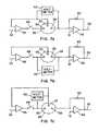
- FIGS. 4 a and 4 bshow embodiments in which two switches are used rather than the single switch of FIG. 3 .
- FIGS. 4 c and 4 dshow embodiments in which one switch is used to effect the isolation.
- FIGS. 5 a , 5 b , and 5 cshow a three-electrode cell system in which it is possible to introduce voltage measurements by providing three switches.
- FIGS. 6 a , 6 b and 6 cshow a three-electrode cell system in which two switches are employed.
- FIGS. 7 a , 7 b , and 7 cshow a three-electrode cell system in which it is possible to introduce voltage measurements by providing one switch.
- FIGS. 8 a , 8 b , and 8 cshow a three-electrode cell system in which another way is shown to introduce voltage measurements by providing one switch.
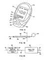
- FIG. 9is a test instrument 70 in side view.
- FIG. 10shows an exemplary schematic diagram of a measurement system according to the invention, in greater detail than in the previous figures.
- FIG. 11is a perspective view of a test instrument 70 .
- FIG. 12shows a strip having the ability to serve as an optical waveguide.
- FIG. 13shows a functional block 62 which can be the analysis circuit of any of the previously discussed figures.
- FIG. 14shows how, with proper use of analog switches, the number of operational amplifiers may be reduced to as few as two.
- FIGS. 4 a and 4 bshow embodiments in which two switches are used rather than the single switch of FIG. 3 . In each embodiment, two switches are opened to isolate the cell for purposes of voltage measurement by means of voltmeter 42 .
- switches 45 , 46are opened to isolate the two-electrode cell 39 from the output of amplifier 35 and from the feedback path to the inverting input of amplifier 35 .
- switches 44 , 47are opened to isolate the two-electrode cell 39 at both the electrode 41 and the electrode 38 .
- FIGS. 4 c and 4 dshow embodiments in which one switch is used to effect the isolation. In each embodiment, a single switch is opened to isolate the cell for purposes of voltage measurement by means of voltmeter 42 .
- switch 46is opened to isolate the two-electrode cell 39 from the output of amplifier 35 .
- switch 47is opened to isolate the two-electrode cell 39 at the electrode 38 .
- a single feedback resistor 43is shown for simplicity, and is meant to represent the selector 31 and the current-range resistors 30 .
- switch 46isolates the electrode 36 from the output of amplifier 35
- switch 45isolates the electrode 37 from the feedback path of amplifier 35
- switch 47isolates the electrode 38 from the amperometric circuitry 32 . In this way all three electrodes of the cell 39 are “floating” relative to other circuitry.
- the voltage being measuredis between the reference electrode 37 and the working electrode 38 ( FIG. 5 a ), or between the counter electrode 36 and the working electrode 38 ( FIG. 5 b ), or between the reference electrode 37 and the counter electrode 36 ( FIG. 5 c ).
- switch 45isolates the electrode 37 from the feedback path of amplifier 35 .
- switch 47isolates the electrode 38 from the amperometric circuitry 32 .
- switch 46isolates the electrode 36 from the output of amplifier 35 .
- a voltmeterto measure voltages.
- the voltage being measuredis between the reference electrode 37 and the working electrode 38 ( FIG. 6 a ), or between the counter electrode 36 and the working electrode 38 ( FIG. 6 b ), or between the reference electrode 37 and the counter electrode 36 ( FIG. 6 c ).
- the voltmeter 42instead of being connected to electrode 38 , could be connected instead to ground (which is one of the inputs of amplifier 32 ).
- switch 46isolates the electrode 36 from the output of amplifier 35 .
- the voltage being measuredis between the reference electrode 37 and the working electrode 38 ( FIG. 7 a ), or between the counter electrode 36 and the working electrode 38 ( FIG. 7 b ), or between the reference electrode 37 and the counter electrode 36 ( FIG. 7 c ).
- switch 47isolates the electrode 38 from the amperometric circuitry of amplifier 32 .
- the voltage being measuredis between the reference electrode 37 and the working electrode 38 ( FIG. 8 a ), or between the counter electrode 36 and the working electrode 38 ( FIG. 8 b ), or between the reference electrode 37 and the counter electrode 36 ( FIG. 8 c ).
- FIG. 10shows an exemplary schematic diagram of a measurement system according to the invention, in greater detail than in the previous figures, and corresponding most closely to the embodiment of FIG. 3 .
- Resistor bank 30may be seen, which together with selector 31 permits selecting feedback resistor values for amplifier 32 .
- the output at 33is a voltage indicative of the current passing through working electrode 38 .
- Selector 31 in this embodimentis a single-pole double-throw switch with selectable sources S 1 , S 2 and a destination D, controlled by control input IN, connected to control line 53 .
- Two-electrode cell 39may be seen in FIG. 10 , with electrode 41 serving as combined counter electrode and reference electrode.
- Integrated circuit 50 of FIG. 10contains four switches.
- One of the switches of circuit 50is a switch 55 at pins 8 , 6 , 7 (input 4 , source 4 , and drain 4 respectively).
- This switch 55corresponds to switch 44 in FIG. 3 , and isolates the electrode 41 from the driver of amplifier 35 .
- amplifier 51When the switch 55 is opened, it is possible to use amplifier 51 as a voltmeter, measuring the voltage between inverting pin 2 and noninverting pin 3 , thereby measuring the voltage between the two electrodes 38 , 41 of the cell 39 .
- the voltage at output 52is proportional to the voltage measured at the inputs of amplifier 51 .
- the opening and closing of the switch 55is controlled by control line 54 .
- control line 54It should also be appreciated that with appropriate switching, as discussed below, it is possible to use a smaller number of amplifiers in a way that fulfills the roles of both the amperometric circuitry and the potentiometic circuitry.
- FIG. 10What is shown in FIG. 10 is thus a powerful and versatile analysis circuit that permits at some times measuring voltage across the electrodes of an electrochemical cell, and that permits at other times performing amperometric measurements across those same electrodes. This permits an automated means of switching between modes.
- the apparatusdiffers from prior-art electrochemical analytic instruments which can operate in a potentiostat (amperometic) mode or in a galvanostat (potentiometic) mode, but which require a human operator to make a manual selection of one mode or the other.
- the apparatus of FIG. 10can also monitor voltage during an amperometric measurement if certain switches are closed. In other words, the amperometric and potentiometric measurements need not be at exclusive times.
- amperometric and potentiometric modesneed not be at fixed and predetermined times, but can instead be performed dynamically depending upon predetermined criteria.
- a measurementcould initially be an amperometric measurement, with the apparatus switching to potentiometric measurement after detection of some particular event in the course of the amperometric measurement.
- FIG. 13what is shown is a functional block 62 which can be the analysis circuit of any of the previously discussed figures.
- a voltage input 34may be seen as well as an output 33 indicative of current in an amperometric measurement.
- the functional block 62may comprise a three-terminal reaction cell 39 or a two-terminal reaction cell 39 as described in connection with the previously discussed figures.
- a voltage output 52 indicative of voltage measured by a voltmeter 42may be omitted for clarity in FIG. 13 .
- one or two or three switchesare used to isolate the cell 39 to permit potential (voltage) measurement.
- input 34is connected to a digital-to-analog converter (DAC) 60 which receives a digital input 61 .
- DACdigital-to-analog converter
- the DACis a fast and accurate DAC, generating complex waveforms as a function of time at the output 63 which is in turn connected with the input 34 of the block 62 .
- the DACcan be a less expensive circuit.
- itmay turn out that it can be a simple resistor ladder connected to discrete outputs from a controller.
- a pulse-width-modulated output from a controllercan be used to charge or discharge a capacitor, giving rise to a desired output at 63 and thus an input at 34 .
- Such a circuitmay be seen for example in co-pending application Ser. No. 10/907,806, which application is incorporated herein by reference for all purposes.
- reaction cells 39for example ramps and sinusoids.
- the benefits of the inventionfor example the use of automatically controlled switching between amperometric and potentiometic modes, and the use of time-variant voltage inputs for the amperometric measurements, offer themselves not only for the glucose measurement mentioned above, but for myriad other measurements including blood chemistry and urine chemistry measurements, as well as immunoassays, cardiac monitoring, and coagulation analysis.
- FIG. 11what is shown is a perspective view of a test instrument 70 .
- a display 71provides information to a user, and pushbuttons 78 , 79 , 80 permit inputs by the user.
- Display 71is preferably a liquid-crystal display but other technologies may also be employed.
- Large seven-segment digits 72permit a large portrayal of an important number such as a blood glucose level.
- a rectangular array of low-resolution circles or other areascan show, in a rough way, qualitative information. This may include hematocrit level, a multi-day history trend graph, a filling rate, a temperature, a battery life, or memory/voice-message space remaining.
- the arraycan also be used to show “progress bars” which help the human user to appreciate that progress is being made in a particular analysis.
- the arraymay be fifteen circles wide and six rows high.
- one way to use the displayis to show a very rough bar graph in which the horizontal axis represents the passage of time and in which the vertical axis represents a quantity of interest. For each time interval there may be none, one, two, or three, four, five, or six circles turned on, starting from the bottom of the array.
- Another way to use the displayis to show a very rough bar graph with between none and fifteen circles turned on, starting at the left edge of the array.
- a modest number of circlesmay be used in a flexible way to show quantitative information in two different ways.
- the circlesare preferably addressed individually by means of respective traces to a connector at an edge of the liquid-crystal display. Alternatively they may addressed by row and column electrodes.
- the number of circles in a rowmay be fifteen.
- FIG. 9what is shown is a test instrument 70 in side view.
- a test strip 90containing an electrochemical cell 39 (omitted for clarity in FIG. 9 ), is inserted into the test instrument 70 by means of movement to the right in FIG. 9 .
- the user of the test instrument 70may have difficulty inserting the test strip 90 into the instrument 70 . This may happen because the user has limited hand-eye coordination or limited fine-motor control. Alternatively, this may happen because the user is in a place that is not well lit, for example while camping and at night. In either case, the user can benefit from a light-emitting diode (LED) 91 which is used to light up the area of the test strip 90 . There is a connector 93 into which the strip 90 is inserted, and the LED 91 is preferably illuminated before the strip 90 is inserted.
- LEDlight-emitting diode
- the usercan illuminate the LED before inserting the strip. This may be done by pressing a button, for example. This may cast light along path 92 , illuminating the tip of the strip. It may also cast light upon the connector 93 , or both.
- the strip 90 as shown in FIG. 12may have the ability (due to being partly or largely transparent) to serve as an optical waveguide. For example many adhesives usable in the manufacture of such strips are transparent. Light can pass along the length of the strip as shown at 95 , emitted at the end as shown at 96 . In this way it is possible to illuminate the lanced area (the area that has been pricked to produce a drop of blood) so that the tip of the strip 90 can be readily guided to the location of the drop of blood.
- the lanced areathe area that has been pricked to produce a drop of blood
- the light-transmitting section of the strip 90may be substantially transparent, or may be fluorescent or phosphorescent, so that the strip lights up and is easy to see.
- FIG. 14a circuit requiring only two operational amplifiers 122 , 137 is shown.
- Operational amplifier 122serves as a unity-gain amplifier (buffer) applying voltage V 2 to the working electrode 120 .
- Pulse-width-modulated control line 123turns transistors 124 , 125 on and off to develop some desired voltage through low-pass filter network 126 .
- This developed voltage V 2is measured at line 127 , which in a typical case goes to an analog-to-digital converter for example at a microcontroller, all omitted for clarity in FIG. 14 .
- switch 133is open and switches 134 and 132 are closed.
- a reference voltage VREF at 136develops a voltage V 1 ( 135 ) which is measured, preferably by means of an analog-to-digital converter omitted for clarity in FIG. 14 .
- This voltageis provided to an input of amplifier 137 , and defines the voltage presented to the electrode 121 .
- the voltage developed at 128is, during this phase, indicative of the current through the reaction cell 130 .
- switch 133is closed and switches 134 and 132 are opened. In this way the potential at the electrode 121 is made available to the amplifier 137 and from there to the sense line 128 .
- the voltage developed at line 128is indicative of the voltage at the electrode 121
- the voltage at electrode 120is defined by the voltage at 127 , and in this way it is possible to measure the potential difference between the electrodes 120 , 121 .
- an apparatus used with a reaction cellhaving a first electrode and a second electrode.
- a voltage sourceprovides a controllable voltage to the first electrode and a voltage sensor senses voltage provided to the first electrode.
- An amplifieris coupled with the second electrode by way of a switch means.
- the switch meansis switchable between first and second positions, the switch means in the first position disposing the amplifier to measure current through the second electrode, thereby measuring current through the reaction cell.
- the switch means in the second positiondisposes the amplifier to measure voltage present at the second electrode.
- the switch means in an exemplary embodimentcomprises first, second, and third analog switches, the first analog switch connecting the second electrode and an inverting input of the amplifier, the second analog switch connecting the second electrode and a non-inverting input of the amplifier, the third analog switch connecting the non-inverting input of the amplifier and a reference voltage.
- the first positionis defined by the first and third switches being closed and the second switch being open, while the second position is defined by the first and third switches being open and the second switch being closed.
- a low-pass filter 129is provided to smooth the signal at line 128 .
Landscapes
- Health & Medical Sciences (AREA)
- Life Sciences & Earth Sciences (AREA)
- Chemical & Material Sciences (AREA)
- General Health & Medical Sciences (AREA)
- Immunology (AREA)
- Electrochemistry (AREA)
- Analytical Chemistry (AREA)
- Biochemistry (AREA)
- Chemical Kinetics & Catalysis (AREA)
- General Physics & Mathematics (AREA)
- Physics & Mathematics (AREA)
- Pathology (AREA)
- Molecular Biology (AREA)
- Hematology (AREA)
- Biophysics (AREA)
- Investigating Or Analysing Biological Materials (AREA)
- Investigating Or Analyzing Materials By The Use Of Electric Means (AREA)
- Investigating Or Analysing Materials By The Use Of Chemical Reactions (AREA)
- Measurement Of The Respiration, Hearing Ability, Form, And Blood Characteristics Of Living Organisms (AREA)
Abstract
Description
Claims (26)
Priority Applications (6)
| Application Number | Priority Date | Filing Date | Title |
|---|---|---|---|
| US13/108,621US8591815B2 (en) | 2004-05-30 | 2011-05-16 | Measuring device and methods for use therewith |
| US13/790,822US8852510B2 (en) | 2004-05-30 | 2013-03-08 | Measuring device and methods for use therewith |
| US14/088,993US9097651B2 (en) | 2004-05-30 | 2013-11-25 | Measuring device and methods for use therewith |
| US14/473,182US9267910B2 (en) | 2004-05-30 | 2014-08-29 | Measuring device and methods for use therewith |
| US14/816,786US9709519B2 (en) | 2004-05-30 | 2015-08-03 | Measuring device and methods for use therewith |
| US15/623,662US10983083B2 (en) | 2004-05-30 | 2017-06-15 | Measuring device and methods for use therewith |
Applications Claiming Priority (4)
| Application Number | Priority Date | Filing Date | Title |
|---|---|---|---|
| US52159204P | 2004-05-30 | 2004-05-30 | |
| US59428505P | 2005-03-25 | 2005-03-25 | |
| US10/907,790US7964146B2 (en) | 2004-05-30 | 2005-04-15 | Measuring device and methods for use therewith |
| US13/108,621US8591815B2 (en) | 2004-05-30 | 2011-05-16 | Measuring device and methods for use therewith |
Related Parent Applications (1)
| Application Number | Title | Priority Date | Filing Date |
|---|---|---|---|
| US10/907,790ContinuationUS7964146B2 (en) | 2004-05-30 | 2005-04-15 | Measuring device and methods for use therewith |
Related Child Applications (2)
| Application Number | Title | Priority Date | Filing Date |
|---|---|---|---|
| US13/790,822DivisionUS8852510B2 (en) | 2004-05-30 | 2013-03-08 | Measuring device and methods for use therewith |
| US14/088,993ContinuationUS9097651B2 (en) | 2004-05-30 | 2013-11-25 | Measuring device and methods for use therewith |
Publications (2)
| Publication Number | Publication Date |
|---|---|
| US20110267028A1 US20110267028A1 (en) | 2011-11-03 |
| US8591815B2true US8591815B2 (en) | 2013-11-26 |
Family
ID=35355929
Family Applications (8)
| Application Number | Title | Priority Date | Filing Date |
|---|---|---|---|
| US10/907,790Active2030-03-19US7964146B2 (en) | 2004-05-30 | 2005-04-15 | Measuring device and methods for use therewith |
| US13/108,621Expired - LifetimeUS8591815B2 (en) | 2004-05-30 | 2011-05-16 | Measuring device and methods for use therewith |
| US13/108,682AbandonedUS20110215004A1 (en) | 2004-05-30 | 2011-05-16 | Measuring device and methods for use therewith |
| US13/790,822Expired - LifetimeUS8852510B2 (en) | 2004-05-30 | 2013-03-08 | Measuring device and methods for use therewith |
| US14/088,993Expired - LifetimeUS9097651B2 (en) | 2004-05-30 | 2013-11-25 | Measuring device and methods for use therewith |
| US14/473,182Expired - LifetimeUS9267910B2 (en) | 2004-05-30 | 2014-08-29 | Measuring device and methods for use therewith |
| US14/816,786Expired - LifetimeUS9709519B2 (en) | 2004-05-30 | 2015-08-03 | Measuring device and methods for use therewith |
| US15/623,662Active2026-12-01US10983083B2 (en) | 2004-05-30 | 2017-06-15 | Measuring device and methods for use therewith |
Family Applications Before (1)
| Application Number | Title | Priority Date | Filing Date |
|---|---|---|---|
| US10/907,790Active2030-03-19US7964146B2 (en) | 2004-05-30 | 2005-04-15 | Measuring device and methods for use therewith |
Family Applications After (6)
| Application Number | Title | Priority Date | Filing Date |
|---|---|---|---|
| US13/108,682AbandonedUS20110215004A1 (en) | 2004-05-30 | 2011-05-16 | Measuring device and methods for use therewith |
| US13/790,822Expired - LifetimeUS8852510B2 (en) | 2004-05-30 | 2013-03-08 | Measuring device and methods for use therewith |
| US14/088,993Expired - LifetimeUS9097651B2 (en) | 2004-05-30 | 2013-11-25 | Measuring device and methods for use therewith |
| US14/473,182Expired - LifetimeUS9267910B2 (en) | 2004-05-30 | 2014-08-29 | Measuring device and methods for use therewith |
| US14/816,786Expired - LifetimeUS9709519B2 (en) | 2004-05-30 | 2015-08-03 | Measuring device and methods for use therewith |
| US15/623,662Active2026-12-01US10983083B2 (en) | 2004-05-30 | 2017-06-15 | Measuring device and methods for use therewith |
Country Status (9)
| Country | Link |
|---|---|
| US (8) | US7964146B2 (en) |
| EP (2) | EP3141899A1 (en) |
| JP (1) | JP2008501115A (en) |
| KR (1) | KR101214001B1 (en) |
| CN (1) | CN102323309B (en) |
| AU (2) | AU2005250661B2 (en) |
| CA (2) | CA2565549C (en) |
| NO (1) | NO20066083L (en) |
| WO (1) | WO2005119234A2 (en) |
Cited By (1)
| Publication number | Priority date | Publication date | Assignee | Title |
|---|---|---|---|---|
| US20150083587A1 (en)* | 2004-05-30 | 2015-03-26 | Agamatrix, Inc. | Measuring Device and Methods for Use Therewith |
Families Citing this family (105)
| Publication number | Priority date | Publication date | Assignee | Title |
|---|---|---|---|---|
| US6036924A (en) | 1997-12-04 | 2000-03-14 | Hewlett-Packard Company | Cassette of lancet cartridges for sampling blood |
| US6391005B1 (en) | 1998-03-30 | 2002-05-21 | Agilent Technologies, Inc. | Apparatus and method for penetration with shaft having a sensor for sensing penetration depth |
| DE10057832C1 (en) | 2000-11-21 | 2002-02-21 | Hartmann Paul Ag | Blood analysis device has syringe mounted in casing, annular mounting carrying needles mounted behind test strip and being swiveled so that needle can be pushed through strip and aperture in casing to take blood sample |
| US8641644B2 (en) | 2000-11-21 | 2014-02-04 | Sanofi-Aventis Deutschland Gmbh | Blood testing apparatus having a rotatable cartridge with multiple lancing elements and testing means |
| US7344507B2 (en) | 2002-04-19 | 2008-03-18 | Pelikan Technologies, Inc. | Method and apparatus for lancet actuation |
| US8337419B2 (en) | 2002-04-19 | 2012-12-25 | Sanofi-Aventis Deutschland Gmbh | Tissue penetration device |
| EP1395185B1 (en) | 2001-06-12 | 2010-10-27 | Pelikan Technologies Inc. | Electric lancet actuator |
| JP4209767B2 (en) | 2001-06-12 | 2009-01-14 | ペリカン テクノロジーズ インコーポレイテッド | Self-optimized cutting instrument with adaptive means for temporary changes in skin properties |
| US9226699B2 (en) | 2002-04-19 | 2016-01-05 | Sanofi-Aventis Deutschland Gmbh | Body fluid sampling module with a continuous compression tissue interface surface |
| AU2002344825A1 (en) | 2001-06-12 | 2002-12-23 | Pelikan Technologies, Inc. | Method and apparatus for improving success rate of blood yield from a fingerstick |
| JP4272051B2 (en) | 2001-06-12 | 2009-06-03 | ペリカン テクノロジーズ インコーポレイテッド | Blood sampling apparatus and method |
| US9795747B2 (en) | 2010-06-02 | 2017-10-24 | Sanofi-Aventis Deutschland Gmbh | Methods and apparatus for lancet actuation |
| US9427532B2 (en) | 2001-06-12 | 2016-08-30 | Sanofi-Aventis Deutschland Gmbh | Tissue penetration device |
| US7981056B2 (en) | 2002-04-19 | 2011-07-19 | Pelikan Technologies, Inc. | Methods and apparatus for lancet actuation |
| WO2002101359A2 (en) | 2001-06-12 | 2002-12-19 | Pelikan Technologies, Inc. | Integrated blood sampling analysis system with multi-use sampling module |
| US7041068B2 (en) | 2001-06-12 | 2006-05-09 | Pelikan Technologies, Inc. | Sampling module device and method |
| US7749174B2 (en) | 2001-06-12 | 2010-07-06 | Pelikan Technologies, Inc. | Method and apparatus for lancet launching device intergrated onto a blood-sampling cartridge |
| US7344894B2 (en) | 2001-10-16 | 2008-03-18 | Agilent Technologies, Inc. | Thermal regulation of fluidic samples within a diagnostic cartridge |
| US8260393B2 (en) | 2003-07-25 | 2012-09-04 | Dexcom, Inc. | Systems and methods for replacing signal data artifacts in a glucose sensor data stream |
| US8010174B2 (en) | 2003-08-22 | 2011-08-30 | Dexcom, Inc. | Systems and methods for replacing signal artifacts in a glucose sensor data stream |
| US7297122B2 (en) | 2002-04-19 | 2007-11-20 | Pelikan Technologies, Inc. | Method and apparatus for penetrating tissue |
| US7901362B2 (en) | 2002-04-19 | 2011-03-08 | Pelikan Technologies, Inc. | Method and apparatus for penetrating tissue |
| US8267870B2 (en) | 2002-04-19 | 2012-09-18 | Sanofi-Aventis Deutschland Gmbh | Method and apparatus for body fluid sampling with hybrid actuation |
| US7582099B2 (en) | 2002-04-19 | 2009-09-01 | Pelikan Technologies, Inc | Method and apparatus for penetrating tissue |
| US9795334B2 (en) | 2002-04-19 | 2017-10-24 | Sanofi-Aventis Deutschland Gmbh | Method and apparatus for penetrating tissue |
| US9248267B2 (en) | 2002-04-19 | 2016-02-02 | Sanofi-Aventis Deustchland Gmbh | Tissue penetration device |
| US7674232B2 (en) | 2002-04-19 | 2010-03-09 | Pelikan Technologies, Inc. | Method and apparatus for penetrating tissue |
| US7371247B2 (en) | 2002-04-19 | 2008-05-13 | Pelikan Technologies, Inc | Method and apparatus for penetrating tissue |
| US7524293B2 (en) | 2002-04-19 | 2009-04-28 | Pelikan Technologies, Inc. | Method and apparatus for penetrating tissue |
| US7232451B2 (en) | 2002-04-19 | 2007-06-19 | Pelikan Technologies, Inc. | Method and apparatus for penetrating tissue |
| US7563232B2 (en) | 2002-04-19 | 2009-07-21 | Pelikan Technologies, Inc. | Method and apparatus for penetrating tissue |
| US7491178B2 (en) | 2002-04-19 | 2009-02-17 | Pelikan Technologies, Inc. | Method and apparatus for penetrating tissue |
| US7648468B2 (en) | 2002-04-19 | 2010-01-19 | Pelikon Technologies, Inc. | Method and apparatus for penetrating tissue |
| US7141058B2 (en) | 2002-04-19 | 2006-11-28 | Pelikan Technologies, Inc. | Method and apparatus for a body fluid sampling device using illumination |
| US7331931B2 (en) | 2002-04-19 | 2008-02-19 | Pelikan Technologies, Inc. | Method and apparatus for penetrating tissue |
| US7229458B2 (en) | 2002-04-19 | 2007-06-12 | Pelikan Technologies, Inc. | Method and apparatus for penetrating tissue |
| US7717863B2 (en) | 2002-04-19 | 2010-05-18 | Pelikan Technologies, Inc. | Method and apparatus for penetrating tissue |
| US8221334B2 (en) | 2002-04-19 | 2012-07-17 | Sanofi-Aventis Deutschland Gmbh | Method and apparatus for penetrating tissue |
| US7547287B2 (en) | 2002-04-19 | 2009-06-16 | Pelikan Technologies, Inc. | Method and apparatus for penetrating tissue |
| US7291117B2 (en) | 2002-04-19 | 2007-11-06 | Pelikan Technologies, Inc. | Method and apparatus for penetrating tissue |
| US8702624B2 (en) | 2006-09-29 | 2014-04-22 | Sanofi-Aventis Deutschland Gmbh | Analyte measurement device with a single shot actuator |
| US7909778B2 (en) | 2002-04-19 | 2011-03-22 | Pelikan Technologies, Inc. | Method and apparatus for penetrating tissue |
| US7374544B2 (en) | 2002-04-19 | 2008-05-20 | Pelikan Technologies, Inc. | Method and apparatus for penetrating tissue |
| US7410468B2 (en) | 2002-04-19 | 2008-08-12 | Pelikan Technologies, Inc. | Method and apparatus for penetrating tissue |
| US7892183B2 (en) | 2002-04-19 | 2011-02-22 | Pelikan Technologies, Inc. | Method and apparatus for body fluid sampling and analyte sensing |
| US9314194B2 (en) | 2002-04-19 | 2016-04-19 | Sanofi-Aventis Deutschland Gmbh | Tissue penetration device |
| US8579831B2 (en) | 2002-04-19 | 2013-11-12 | Sanofi-Aventis Deutschland Gmbh | Method and apparatus for penetrating tissue |
| US8784335B2 (en) | 2002-04-19 | 2014-07-22 | Sanofi-Aventis Deutschland Gmbh | Body fluid sampling device with a capacitive sensor |
| US7481776B2 (en) | 2002-04-19 | 2009-01-27 | Pelikan Technologies, Inc. | Method and apparatus for penetrating tissue |
| US7976476B2 (en) | 2002-04-19 | 2011-07-12 | Pelikan Technologies, Inc. | Device and method for variable speed lancet |
| US7708701B2 (en) | 2002-04-19 | 2010-05-04 | Pelikan Technologies, Inc. | Method and apparatus for a multi-use body fluid sampling device |
| US8574895B2 (en) | 2002-12-30 | 2013-11-05 | Sanofi-Aventis Deutschland Gmbh | Method and apparatus using optical techniques to measure analyte levels |
| US7850621B2 (en) | 2003-06-06 | 2010-12-14 | Pelikan Technologies, Inc. | Method and apparatus for body fluid sampling and analyte sensing |
| WO2006001797A1 (en) | 2004-06-14 | 2006-01-05 | Pelikan Technologies, Inc. | Low pain penetrating |
| EP1635700B1 (en) | 2003-06-13 | 2016-03-09 | Sanofi-Aventis Deutschland GmbH | Apparatus for a point of care device |
| US20080119703A1 (en) | 2006-10-04 | 2008-05-22 | Mark Brister | Analyte sensor |
| US20190357827A1 (en) | 2003-08-01 | 2019-11-28 | Dexcom, Inc. | Analyte sensor |
| US20140121989A1 (en) | 2003-08-22 | 2014-05-01 | Dexcom, Inc. | Systems and methods for processing analyte sensor data |
| US8282576B2 (en) | 2003-09-29 | 2012-10-09 | Sanofi-Aventis Deutschland Gmbh | Method and apparatus for an improved sample capture device |
| EP1680014A4 (en) | 2003-10-14 | 2009-01-21 | Pelikan Technologies Inc | METHOD AND DEVICE FOR A VARIABLE USER INTERFACE |
| US8364231B2 (en) | 2006-10-04 | 2013-01-29 | Dexcom, Inc. | Analyte sensor |
| EP2301428B1 (en) | 2003-12-09 | 2016-11-30 | Dexcom, Inc. | Signal processing for continuous analyte sensor |
| US8668656B2 (en) | 2003-12-31 | 2014-03-11 | Sanofi-Aventis Deutschland Gmbh | Method and apparatus for improving fluidic flow and sample capture |
| US7822454B1 (en) | 2005-01-03 | 2010-10-26 | Pelikan Technologies, Inc. | Fluid sampling device with improved analyte detecting member configuration |
| WO2006011062A2 (en) | 2004-05-20 | 2006-02-02 | Albatros Technologies Gmbh & Co. Kg | Printable hydrogel for biosensors |
| WO2005120365A1 (en) | 2004-06-03 | 2005-12-22 | Pelikan Technologies, Inc. | Method and apparatus for a fluid sampling device |
| US8652831B2 (en) | 2004-12-30 | 2014-02-18 | Sanofi-Aventis Deutschland Gmbh | Method and apparatus for analyte measurement test time |
| US7547382B2 (en) | 2005-04-15 | 2009-06-16 | Agamatrix, Inc. | Determination of partial fill in electrochemical strips |
| US7964089B2 (en) | 2005-04-15 | 2011-06-21 | Agamatrix, Inc. | Analyte determination method and analyte meter |
| US7774038B2 (en) | 2005-12-30 | 2010-08-10 | Medtronic Minimed, Inc. | Real-time self-calibrating sensor system and method |
| US7438694B2 (en)* | 2006-03-07 | 2008-10-21 | Agamatrix, Inc. | Lancing device |
| US8257651B2 (en)* | 2006-03-16 | 2012-09-04 | Agamatrix, Inc. | Analyte meter with rotatable user interface |
| US8162968B2 (en)* | 2006-04-10 | 2012-04-24 | Agamatrix, Inc. | Lancing device |
| WO2008049074A2 (en)* | 2006-10-18 | 2008-04-24 | Agamatrix, Inc. | Error detection in analyte measurements based on measurement of system resistance |
| JP5027819B2 (en)* | 2006-11-30 | 2012-09-19 | パナソニック株式会社 | Blood test equipment |
| WO2008085251A1 (en)* | 2007-01-05 | 2008-07-17 | Bayer Healthcare Llc | Electrochemical test sensor with light guide |
| US7794658B2 (en) | 2007-07-25 | 2010-09-14 | Lifescan, Inc. | Open circuit delay devices, systems, and methods for analyte measurement |
| EP2584044B1 (en) | 2007-07-26 | 2015-04-22 | Agamatrix, Inc. | Electrochemical analyte detections apparatus and method |
| EP2265324B1 (en) | 2008-04-11 | 2015-01-28 | Sanofi-Aventis Deutschland GmbH | Integrated analyte measurement system |
| KR20140117698A (en)* | 2008-07-07 | 2014-10-07 | 아가매트릭스, 인코포레이티드 | Integrated blood glucose measurement device |
| US8465977B2 (en)* | 2008-07-22 | 2013-06-18 | Roche Diagnostics Operations, Inc. | Method and apparatus for lighted test strip |
| US9375169B2 (en) | 2009-01-30 | 2016-06-28 | Sanofi-Aventis Deutschland Gmbh | Cam drive for managing disposable penetrating member actions with a single motor and motor and control system |
| US20100249965A1 (en)* | 2009-03-31 | 2010-09-30 | Agamatrix, Inc. | Integrated Blood Glucose Measurement Device |
| US8965476B2 (en) | 2010-04-16 | 2015-02-24 | Sanofi-Aventis Deutschland Gmbh | Tissue penetration device |
| US8431408B2 (en) | 2010-10-15 | 2013-04-30 | Roche Diagnostics Operations, Inc. | Handheld diabetes managing device with light pipe for enhanced illumination |
| EP2672263B1 (en)* | 2011-02-02 | 2022-05-04 | PHC Holdings Corporation | Biological sample measuring device |
| EP2697650B1 (en) | 2011-04-15 | 2020-09-30 | Dexcom, Inc. | Advanced analyte sensor calibration and error detection |
| KR20190026948A (en) | 2011-07-27 | 2019-03-13 | 아가매트릭스, 인코포레이티드 | Reagents for electrochemical test strips |
| CN104380094B (en)* | 2012-03-08 | 2018-07-20 | 帕克-汉尼芬公司 | Analyte sensing device |
| US8894262B2 (en) | 2013-03-11 | 2014-11-25 | Roche Diagnostic Operations, Inc. | Blood glucose test strip illumination device and method |
| GB2513157B (en)* | 2013-04-17 | 2016-01-06 | Lifescan Scotland Ltd | Hand-held test meter with display illumination adjustment circuit block |
| US9442089B2 (en) | 2013-12-23 | 2016-09-13 | Lifescan Scotland Limited | Analyte meter test strip detection |
| US10036709B2 (en) | 2014-05-20 | 2018-07-31 | Roche Diabetes Care, Inc. | BG meter illuminated test strip |
| US9632059B2 (en)* | 2015-09-03 | 2017-04-25 | Ashwin-Ushas Corporation, Inc. | Potentiostat/galvanostat with digital interface |
| US12109032B1 (en) | 2017-03-11 | 2024-10-08 | Biolinq Incorporated | Methods for achieving an isolated electrical interface between an anterior surface of a microneedle structure and a posterior surface of a support structure |
| US11045142B1 (en) | 2017-04-29 | 2021-06-29 | Biolinq, Inc. | Heterogeneous integration of silicon-fabricated solid microneedle sensors and CMOS circuitry |
| EP3399308B1 (en)* | 2017-05-05 | 2023-06-07 | NeoSense Technologies AB | Oxygen sensor |
| CN109655752B (en)* | 2018-12-22 | 2021-03-16 | 北京工业大学 | A three-electrode metal-air battery test mold with positive anti-fluctuation interference |
| JP7567175B2 (en)* | 2020-03-02 | 2024-10-16 | 富士通オプティカルコンポーネンツ株式会社 | Optical device and optical device test method |
| SE2251496A1 (en) | 2020-07-29 | 2022-12-20 | Biolinq Incorporated | Continuous analyte monitoring system with microneedle array |
| EP3945313A1 (en)* | 2020-07-30 | 2022-02-02 | Fundacio Institut de Bioenginyeria de Catalunya | Electrochemical sensor systems for sensing analytical reactions and biological operations and methods |
| CN114813883B (en)* | 2021-01-20 | 2024-10-15 | 浙江亿联康医疗科技有限公司 | Method for measuring reaction current of electrochemical sensor |
| CA3184224A1 (en) | 2021-05-08 | 2022-11-17 | Joshua Ray Windmiller | Fault detection for microneedle array based continuous analyte monitoring device |
| US11846600B2 (en)* | 2021-09-01 | 2023-12-19 | Cirrus Logic Inc. | Circuitry for analyte measurement |
| US12336816B2 (en) | 2023-02-02 | 2025-06-24 | Biolinq Incorporated | Method for improved sensor sensitivity of a microneedle-based continuous analyte monitoring system |
Citations (20)
| Publication number | Priority date | Publication date | Assignee | Title |
|---|---|---|---|---|
| SU978027A1 (en) | 1978-03-06 | 1982-11-30 | Всесоюзный Научно-Исследовательский И Конструкторский Институт Научного Приборостроения | Device for electrochemical investigations |
| US4752740A (en) | 1986-05-19 | 1988-06-21 | Steininger Jacques M | Electronic water chemistry analysis device with linear bargraph readouts |
| US4798655A (en) | 1987-03-19 | 1989-01-17 | Howard Diamond | Multiparameter analytical electrode structure and method of measurement |
| US5108564A (en) | 1988-03-15 | 1992-04-28 | Tall Oak Ventures | Method and apparatus for amperometric diagnostic analysis |
| US5124661A (en) | 1990-07-23 | 1992-06-23 | I-Stat Corporation | Reusable test unit for simulating electrochemical sensor signals for quality assurance of portable blood analyzer instruments |
| DE4100727A1 (en) | 1991-01-09 | 1992-07-16 | Klein Karl Dittmar Dr | Measuring analyte concn. with enzyme electrode sensor - by applying voltage pulse to disturb equilibrium, then measuring rate of relaxation, esp. useful in medicine and bio-technology |
| US5540828A (en) | 1987-06-08 | 1996-07-30 | Yacynych; Alexander | Method for making electrochemical sensors and biosensors having a polymer modified surface |
| JPH11235196A (en) | 1998-02-20 | 1999-08-31 | Kdk Corp | Biosensor system |
| US6251260B1 (en) | 1998-08-24 | 2001-06-26 | Therasense, Inc. | Potentiometric sensors for analytic determination |
| US6391558B1 (en) | 1997-03-18 | 2002-05-21 | Andcare, Inc. | Electrochemical detection of nucleic acid sequences |
| WO2002053024A2 (en) | 2001-01-03 | 2002-07-11 | Microlife Intellectual Property Gmbh | A system for measuring at least one body parameter, a blood pressure monitor and a medical thermometer |
| WO2002077633A1 (en) | 2001-03-23 | 2002-10-03 | The Regents Of The University Of California | Open circuit potential amperometry and voltammetry |
| US20030064525A1 (en) | 1997-12-22 | 2003-04-03 | Liess Martin Dieter | Meter |
| WO2003046538A1 (en) | 2001-11-26 | 2003-06-05 | Ischemia Technologies, Inc. | Electrochemical detection of ischemia |
| WO2003056314A2 (en) | 2001-12-22 | 2003-07-10 | Roche Diagnostics Gmbh | Analysis system for determining an analyte concentration, taking into consideration sample- and analyte-independent light-intensity changes |
| WO2003060154A2 (en) | 2002-01-15 | 2003-07-24 | Agamatrix, Inc. | Method and apparatus for processing electrochemical signals |
| WO2003069304A2 (en) | 2002-02-10 | 2003-08-21 | Agamatrix, Inc | Method and apparatus for assay of electrochemical properties |
| US20040146863A1 (en) | 2001-06-11 | 2004-07-29 | Pisharody Sobha M. | Electronic detection of biological molecules using thin layers |
| WO2005022143A2 (en) | 2003-08-21 | 2005-03-10 | Agamatrix, Inc. | Method and apparatus for assay of electrochemical properties |
| US6933153B1 (en) | 1997-09-15 | 2005-08-23 | Vlaamse Instelling Voor Technologish Onderzoek | Metal ion specific capacity affinity sensor |
Family Cites Families (13)
| Publication number | Priority date | Publication date | Assignee | Title |
|---|---|---|---|---|
| US3646814A (en)* | 1970-09-16 | 1972-03-07 | Us Navy | Pressure detector |
| US4001103A (en)* | 1974-05-07 | 1977-01-04 | Energetics Science, Inc. | Device for the detection and measurement of NO and NO2 gases |
| US4628463A (en)* | 1984-03-05 | 1986-12-09 | Georgia Tech. Research Institute | Rapid-sweep electrochemical detector for chemical analysis of flow streams |
| US5096669A (en)* | 1988-09-15 | 1992-03-17 | I-Stat Corporation | Disposable sensing device for real time fluid analysis |
| DE4025088A1 (en)* | 1990-08-08 | 1992-02-13 | Vaw Ver Aluminium Werke Ag | CATHODICAL CORROSION PROTECTION FOR AN ALUMINUM CONTAINING SUBSTRATE |
| US5251126A (en) | 1990-10-29 | 1993-10-05 | Miles Inc. | Diabetes data analysis and interpretation method |
| US5375610A (en)* | 1992-04-28 | 1994-12-27 | University Of New Hampshire | Apparatus for the functional assessment of human activity |
| DE4415896A1 (en) | 1994-05-05 | 1995-11-09 | Boehringer Mannheim Gmbh | Analysis system for monitoring the concentration of an analyte in the blood of a patient |
| US5695949A (en) | 1995-04-07 | 1997-12-09 | Lxn Corp. | Combined assay for current glucose level and intermediate or long-term glycemic control |
| DE19626377A1 (en)* | 1996-07-01 | 1998-01-08 | Dunkel Otto Gmbh | Contact device for the electrical connection of a printed circuit board to a liquid crystal display plate |
| US6514460B1 (en)* | 1999-07-28 | 2003-02-04 | Abbott Laboratories | Luminous glucose monitoring device |
| US7964146B2 (en)* | 2004-05-30 | 2011-06-21 | Agamatrix, Inc. | Measuring device and methods for use therewith |
| US20070000778A1 (en)* | 2005-06-30 | 2007-01-04 | Chung Yuan Christian University | Multi-parameter sensor with readout circuit |
- 2005
- 2005-04-15USUS10/907,790patent/US7964146B2/enactiveActive
- 2005-05-20CACA2565549Apatent/CA2565549C/ennot_activeExpired - Lifetime
- 2005-05-20AUAU2005250661Apatent/AU2005250661B2/ennot_activeExpired
- 2005-05-20CACA2934732Apatent/CA2934732C/ennot_activeExpired - Lifetime
- 2005-05-20JPJP2007514250Apatent/JP2008501115A/enactivePending
- 2005-05-20WOPCT/IB2005/051641patent/WO2005119234A2/ennot_activeApplication Discontinuation
- 2005-05-20EPEP16194235.4Apatent/EP3141899A1/enactivePending
- 2005-05-20EPEP05738406.7Apatent/EP1751545B1/ennot_activeExpired - Lifetime
- 2005-05-20CNCN201110214013.5Apatent/CN102323309B/ennot_activeExpired - Lifetime
- 2006
- 2006-11-29KRKR1020067025163Apatent/KR101214001B1/ennot_activeExpired - Fee Related
- 2006-12-29NONO20066083Apatent/NO20066083L/enunknown
- 2010
- 2010-07-08AUAU2010202887Apatent/AU2010202887A1/ennot_activeAbandoned
- 2011
- 2011-05-16USUS13/108,621patent/US8591815B2/ennot_activeExpired - Lifetime
- 2011-05-16USUS13/108,682patent/US20110215004A1/ennot_activeAbandoned
- 2013
- 2013-03-08USUS13/790,822patent/US8852510B2/ennot_activeExpired - Lifetime
- 2013-11-25USUS14/088,993patent/US9097651B2/ennot_activeExpired - Lifetime
- 2014
- 2014-08-29USUS14/473,182patent/US9267910B2/ennot_activeExpired - Lifetime
- 2015
- 2015-08-03USUS14/816,786patent/US9709519B2/ennot_activeExpired - Lifetime
- 2017
- 2017-06-15USUS15/623,662patent/US10983083B2/enactiveActive
Patent Citations (23)
| Publication number | Priority date | Publication date | Assignee | Title |
|---|---|---|---|---|
| SU978027A1 (en) | 1978-03-06 | 1982-11-30 | Всесоюзный Научно-Исследовательский И Конструкторский Институт Научного Приборостроения | Device for electrochemical investigations |
| US4752740A (en) | 1986-05-19 | 1988-06-21 | Steininger Jacques M | Electronic water chemistry analysis device with linear bargraph readouts |
| US4798655A (en) | 1987-03-19 | 1989-01-17 | Howard Diamond | Multiparameter analytical electrode structure and method of measurement |
| US5540828A (en) | 1987-06-08 | 1996-07-30 | Yacynych; Alexander | Method for making electrochemical sensors and biosensors having a polymer modified surface |
| US5108564A (en) | 1988-03-15 | 1992-04-28 | Tall Oak Ventures | Method and apparatus for amperometric diagnostic analysis |
| US5124661A (en) | 1990-07-23 | 1992-06-23 | I-Stat Corporation | Reusable test unit for simulating electrochemical sensor signals for quality assurance of portable blood analyzer instruments |
| DE4100727A1 (en) | 1991-01-09 | 1992-07-16 | Klein Karl Dittmar Dr | Measuring analyte concn. with enzyme electrode sensor - by applying voltage pulse to disturb equilibrium, then measuring rate of relaxation, esp. useful in medicine and bio-technology |
| US6391558B1 (en) | 1997-03-18 | 2002-05-21 | Andcare, Inc. | Electrochemical detection of nucleic acid sequences |
| US6933153B1 (en) | 1997-09-15 | 2005-08-23 | Vlaamse Instelling Voor Technologish Onderzoek | Metal ion specific capacity affinity sensor |
| US20030064525A1 (en) | 1997-12-22 | 2003-04-03 | Liess Martin Dieter | Meter |
| JPH11235196A (en) | 1998-02-20 | 1999-08-31 | Kdk Corp | Biosensor system |
| US6251260B1 (en) | 1998-08-24 | 2001-06-26 | Therasense, Inc. | Potentiometric sensors for analytic determination |
| WO2002053024A2 (en) | 2001-01-03 | 2002-07-11 | Microlife Intellectual Property Gmbh | A system for measuring at least one body parameter, a blood pressure monitor and a medical thermometer |
| WO2002077633A1 (en) | 2001-03-23 | 2002-10-03 | The Regents Of The University Of California | Open circuit potential amperometry and voltammetry |
| US20040146863A1 (en) | 2001-06-11 | 2004-07-29 | Pisharody Sobha M. | Electronic detection of biological molecules using thin layers |
| WO2003046538A1 (en) | 2001-11-26 | 2003-06-05 | Ischemia Technologies, Inc. | Electrochemical detection of ischemia |
| WO2003056314A2 (en) | 2001-12-22 | 2003-07-10 | Roche Diagnostics Gmbh | Analysis system for determining an analyte concentration, taking into consideration sample- and analyte-independent light-intensity changes |
| US20050054082A1 (en) | 2001-12-22 | 2005-03-10 | Rudolf Pachl | Analysis system for determining an analyte concentration, taking into consideration sample-and analyte-independent light-intensity changes |
| WO2003060154A2 (en) | 2002-01-15 | 2003-07-24 | Agamatrix, Inc. | Method and apparatus for processing electrochemical signals |
| US20030178322A1 (en) | 2002-01-15 | 2003-09-25 | Iyengar Sridhar G. | Method and apparatus for processing electrochemical signals |
| WO2003069304A2 (en) | 2002-02-10 | 2003-08-21 | Agamatrix, Inc | Method and apparatus for assay of electrochemical properties |
| US20050069892A1 (en) | 2002-02-10 | 2005-03-31 | Iyengar Sridhar G. | Method and apparatus for assay of electrochemical properties |
| WO2005022143A2 (en) | 2003-08-21 | 2005-03-10 | Agamatrix, Inc. | Method and apparatus for assay of electrochemical properties |
Non-Patent Citations (1)
| Title |
|---|
| Roth et al., Characterization of charge storage in redox-active self=assembled monolayers, LANGMUIR, 2002, pp. 4030-4040, vol. 18, No. 10, XP002951267, USSBL 0743-7463. |
Cited By (5)
| Publication number | Priority date | Publication date | Assignee | Title |
|---|---|---|---|---|
| US20150083587A1 (en)* | 2004-05-30 | 2015-03-26 | Agamatrix, Inc. | Measuring Device and Methods for Use Therewith |
| US20160033441A1 (en)* | 2004-05-30 | 2016-02-04 | Agamatrix, Inc. | Measuring device and methods for use therewith |
| US9267910B2 (en)* | 2004-05-30 | 2016-02-23 | Agamatrix, Inc. | Measuring device and methods for use therewith |
| US9709519B2 (en)* | 2004-05-30 | 2017-07-18 | Agamatrix, Inc. | Measuring device and methods for use therewith |
| US10983083B2 (en) | 2004-05-30 | 2021-04-20 | Agamatrix, Inc. | Measuring device and methods for use therewith |
Also Published As
| Publication number | Publication date |
|---|---|
| JP2008501115A (en) | 2008-01-17 |
| US9097651B2 (en) | 2015-08-04 |
| CA2934732C (en) | 2019-04-23 |
| US20160033441A1 (en) | 2016-02-04 |
| EP1751545B1 (en) | 2016-10-19 |
| AU2005250661B2 (en) | 2010-08-19 |
| AU2005250661A1 (en) | 2005-12-15 |
| US7964146B2 (en) | 2011-06-21 |
| CA2565549C (en) | 2016-07-19 |
| US10983083B2 (en) | 2021-04-20 |
| US20170350847A1 (en) | 2017-12-07 |
| US20050265094A1 (en) | 2005-12-01 |
| WO2005119234A3 (en) | 2006-07-20 |
| US20150083587A1 (en) | 2015-03-26 |
| NO20066083L (en) | 2006-12-29 |
| CA2565549A1 (en) | 2005-12-15 |
| AU2010202887A1 (en) | 2010-07-29 |
| WO2005119234A2 (en) | 2005-12-15 |
| WO2005119234B1 (en) | 2006-10-19 |
| US20140151222A1 (en) | 2014-06-05 |
| CN102323309B (en) | 2014-12-17 |
| US20110267028A1 (en) | 2011-11-03 |
| CN102323309A (en) | 2012-01-18 |
| US8852510B2 (en) | 2014-10-07 |
| US9267910B2 (en) | 2016-02-23 |
| EP1751545A2 (en) | 2007-02-14 |
| US20140001046A1 (en) | 2014-01-02 |
| KR20070027568A (en) | 2007-03-09 |
| CA2934732A1 (en) | 2005-12-15 |
| EP3141899A1 (en) | 2017-03-15 |
| US20110215004A1 (en) | 2011-09-08 |
| KR101214001B1 (en) | 2012-12-20 |
| US9709519B2 (en) | 2017-07-18 |
Similar Documents
| Publication | Publication Date | Title |
|---|---|---|
| US10983083B2 (en) | Measuring device and methods for use therewith | |
| US20050276133A1 (en) | Measuring device and methods for use therewith | |
| US8030942B2 (en) | Method and apparatus for providing stable voltage to analytical system | |
| KR100540849B1 (en) | Device for quantitative analysis of biomaterials | |
| EP1279033B1 (en) | Electrochemical biosensor test strip with recognition electrode and readout meter using this test strip | |
| CA2444094C (en) | Analyte test instrument having improved versatility | |
| CN101432620B (en) | Underfill detection system for electrochemical biosensor | |
| KR100911927B1 (en) | Measuring device for analysis of biomaterials using colorimetric method | |
| HK1112505A (en) | Measuring device and methods for use therewith | |
| CN101023350A (en) | Measuring equipment and methods for use therewith | |
| US20040003998A1 (en) | Electrophoresis separation apparatus |
Legal Events
| Date | Code | Title | Description |
|---|---|---|---|
| AS | Assignment | Owner name:AGAMATRIX, INC., NEW HAMPSHIRE Free format text:ASSIGNMENT OF ASSIGNORS INTEREST;ASSIGNORS:HARDING, IAN;IYENGAR, SRIDHAR G.;WEI, BAOGUO;AND OTHERS;REEL/FRAME:026458/0604 Effective date:20050524 | |
| STCF | Information on status: patent grant | Free format text:PATENTED CASE | |
| CC | Certificate of correction | ||
| FEPP | Fee payment procedure | Free format text:PAT HOLDER NO LONGER CLAIMS SMALL ENTITY STATUS, ENTITY STATUS SET TO UNDISCOUNTED (ORIGINAL EVENT CODE: STOL); ENTITY STATUS OF PATENT OWNER: LARGE ENTITY | |
| AS | Assignment | Owner name:MIDCAP FINANCIAL TRUST, MARYLAND Free format text:SECURITY INTEREST;ASSIGNOR:AGAMATRIX, INC.;REEL/FRAME:037405/0728 Effective date:20151223 | |
| FPAY | Fee payment | Year of fee payment:4 | |
| AS | Assignment | Owner name:PROSPECT CAPITAL CORPORATION, NEW YORK Free format text:PATENT SECURITY AGREEMENT;ASSIGNOR:AGAMATRIX, INC.;REEL/FRAME:044063/0828 Effective date:20170929 Owner name:AGAMATRIX, INC., NORTH CAROLINA Free format text:RELEASE BY SECURED PARTY;ASSIGNOR:MIDCAP FINANCIAL TRUST;REEL/FRAME:044034/0372 Effective date:20170929 | |
| AS | Assignment | Owner name:AGAMATRIX, INC., NEW HAMPSHIRE Free format text:CORRECTIVE ASSIGNMENT TO CORRECT THE ASSIGNEE ADDRESS PREVIOUSLY RECORDED AT REEL: 044034 FRAME: 0372. ASSIGNOR(S) HEREBY CONFIRMS THE RELEASE OF SECURITY INTEREST;ASSIGNOR:MIDCAP FINANCIAL TRUST;REEL/FRAME:044391/0941 Effective date:20170929 | |
| MAFP | Maintenance fee payment | Free format text:PAYMENT OF MAINTENANCE FEE, 8TH YEAR, LARGE ENTITY (ORIGINAL EVENT CODE: M1552); ENTITY STATUS OF PATENT OWNER: LARGE ENTITY Year of fee payment:8 | |
| AS | Assignment | Owner name:AGAMATRIX, INC., NEW HAMPSHIRE Free format text:RELEASE OF PATENT SECURITY AGREEMENT;ASSIGNOR:PROSPECT CAPITAL CORPORATION, AS COLLATERAL AGENT;REEL/FRAME:063604/0749 Effective date:20230505 | |
| MAFP | Maintenance fee payment | Free format text:PAYMENT OF MAINTENANCE FEE, 12TH YEAR, LARGE ENTITY (ORIGINAL EVENT CODE: M1553); ENTITY STATUS OF PATENT OWNER: LARGE ENTITY Year of fee payment:12 |