US8591634B2 - Method and equipment for selectively collecting process effluent - Google Patents
Method and equipment for selectively collecting process effluentDownload PDFInfo
- Publication number
- US8591634B2 US8591634B2US13/009,400US201113009400AUS8591634B2US 8591634 B2US8591634 B2US 8591634B2US 201113009400 AUS201113009400 AUS 201113009400AUS 8591634 B2US8591634 B2US 8591634B2
- Authority
- US
- United States
- Prior art keywords
- effluent
- gas
- line
- chemical process
- desired gas
- Prior art date
- Legal status (The legal status is an assumption and is not a legal conclusion. Google has not performed a legal analysis and makes no representation as to the accuracy of the status listed.)
- Active, expires
Links
Images


Classifications
- C—CHEMISTRY; METALLURGY
- C01—INORGANIC CHEMISTRY
- C01B—NON-METALLIC ELEMENTS; COMPOUNDS THEREOF; METALLOIDS OR COMPOUNDS THEREOF NOT COVERED BY SUBCLASS C01C
- C01B23/00—Noble gases; Compounds thereof
- B—PERFORMING OPERATIONS; TRANSPORTING
- B01—PHYSICAL OR CHEMICAL PROCESSES OR APPARATUS IN GENERAL
- B01D—SEPARATION
- B01D53/00—Separation of gases or vapours; Recovering vapours of volatile solvents from gases; Chemical or biological purification of waste gases, e.g. engine exhaust gases, smoke, fumes, flue gases, aerosols
- B01D53/02—Separation of gases or vapours; Recovering vapours of volatile solvents from gases; Chemical or biological purification of waste gases, e.g. engine exhaust gases, smoke, fumes, flue gases, aerosols by adsorption, e.g. preparative gas chromatography
- B01D53/04—Separation of gases or vapours; Recovering vapours of volatile solvents from gases; Chemical or biological purification of waste gases, e.g. engine exhaust gases, smoke, fumes, flue gases, aerosols by adsorption, e.g. preparative gas chromatography with stationary adsorbents
- B—PERFORMING OPERATIONS; TRANSPORTING
- B01—PHYSICAL OR CHEMICAL PROCESSES OR APPARATUS IN GENERAL
- B01D—SEPARATION
- B01D53/00—Separation of gases or vapours; Recovering vapours of volatile solvents from gases; Chemical or biological purification of waste gases, e.g. engine exhaust gases, smoke, fumes, flue gases, aerosols
- B01D53/34—Chemical or biological purification of waste gases
- B01D53/73—After-treatment of removed components
- B—PERFORMING OPERATIONS; TRANSPORTING
- B01—PHYSICAL OR CHEMICAL PROCESSES OR APPARATUS IN GENERAL
- B01D—SEPARATION
- B01D2256/00—Main component in the product gas stream after treatment
- B01D2256/18—Noble gases
- B—PERFORMING OPERATIONS; TRANSPORTING
- B01—PHYSICAL OR CHEMICAL PROCESSES OR APPARATUS IN GENERAL
- B01D—SEPARATION
- B01D2258/00—Sources of waste gases
- B01D2258/02—Other waste gases
- B01D2258/0216—Other waste gases from CVD treatment or semi-conductor manufacturing
- B—PERFORMING OPERATIONS; TRANSPORTING
- B01—PHYSICAL OR CHEMICAL PROCESSES OR APPARATUS IN GENERAL
- B01D—SEPARATION
- B01D2259/00—Type of treatment
- B01D2259/40—Further details for adsorption processes and devices
- B01D2259/402—Further details for adsorption processes and devices using two beds
- Y—GENERAL TAGGING OF NEW TECHNOLOGICAL DEVELOPMENTS; GENERAL TAGGING OF CROSS-SECTIONAL TECHNOLOGIES SPANNING OVER SEVERAL SECTIONS OF THE IPC; TECHNICAL SUBJECTS COVERED BY FORMER USPC CROSS-REFERENCE ART COLLECTIONS [XRACs] AND DIGESTS
- Y10—TECHNICAL SUBJECTS COVERED BY FORMER USPC
- Y10T—TECHNICAL SUBJECTS COVERED BY FORMER US CLASSIFICATION
- Y10T137/00—Fluid handling
- Y10T137/7722—Line condition change responsive valves
- Y10T137/7837—Direct response valves [i.e., check valve type]
Definitions
- Etchant gases from semiconductor processingare known to be recovered because of global warming potential. See U.S. Pat. No. 7,258,725.
- Xenon sensorsare known. See US2006/00211421.
- the present inventionis an apparatus for recovering a desired gas from the effluent of a chemical process reactor that utilizes two or more gas compositions in sequence, comprising;
- the present inventionis also a process for recovering a desired gas from the effluent of a chemical process reactor that utilizes two or more gas compositions in sequence, comprising;
- FIG. 1is a schematic illustration of an embodiment of the present invention for collecting a desired gas in a discrete manner from a chemical process reactor effluent.
- FIG. 2is a partial section of FIG. 1 showing an alternate valve arrangement using three-way valve 20 A.
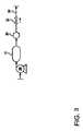
- FIG. 3is a partial section of FIG. 1 showing an embodiment with a buffer tank 31 downstream of the compressor 28 and upstream of the guard bed 30 .
- An alternate approachis to utilize an onboard sensor after the chemical process reactor, such as in the effluent line from the chemical process reactor.
- the sensorwould detect the presense of the species of interest, such as a desired gas exemplified by xenon, and activate the process controller to initiate recovery or collection of such gas.
- Actuation of the automatic valveis controlled by logic based on measurement of key process parameters.
- the systemincludes process equipment that provides vacuum and capacity needed to collect and store the desired gas. Such equipment creates an appropriate level of capacity, such that a steady flow of desired gas contained in an effluent gas can be metered into an enrichment system, such as a vacuum swing adsorption system (VSA), temperature swing adsorption system (TSA), or pressure swing adsorption system (PSA).
- VSAvacuum swing adsorption system
- TSAtemperature swing adsorption system
- PSApressure swing adsorption system
- the methodcomprises a system for monitoring/measuring the process parameters, logic for control, an automatic valve to divert the gas when selected, a check valve, a vacuum system, and storage volume.
- the interfaceoperates by utilizing a pressure difference between the recovery gas manifold or recovery line and the normal waste gas manifold or effluent line after the process pumps/compressors.
- an automatic valvesuch as a solenoid valve is opened. The reduced pressure within the recovery line forces closure of a check valve in the effluent line.
- the systemalso contains process logic to selectively signal when the species of interest or desired gas is present, as well as to shut-off flow, if the species of interest or desired gas is not present, or another species is present that could cause disruptions to the downstream recovery system.
- the process logiccan also compensate for the time required for the species of interest or desired gas, such as xenon, to travel from the chemical process reactor to the recovery line or automatic valve. This is accomplished by an adjustable delay in the opening and closing of the automatic valve.
- the interface with the chemical process reactormay comprise a tee to tap into the effluent line, a shutoff valve, an analytical port (optional), a flex line to reduce vibrational coupling and stresses, a pressure gauge (optional), solenoid valve, and a manual shutoff valve to enable isolation of the chemical process reactor from the recovery system.
- Effluent gas from semiconductor or chemical process reactor, such as etchingtypically are diluted at the process pump and then transferred through a gas manifold or effluent line after the pump into a common effluent gas manifold that eventually goes to an abatement or scrubbing system.
- This comingling of effluent gaseseventually dilutes the process effluent compositions and the desired gas of interest, making it very difficult to efficiently process to remove the species of interest or desired gas for recovery.
- the desired gas of interestbe segregated from the other effluent streams prior to arrival in the common header. For this to be accomplished the desired gas of interest is diverted towards the recovery system between the process chambers and entrance to the common header.
- this diversionmust be performed in a manner that prevents any interference with the flow of process gases through the chemical process reactor. Such disruptions could cause failures in the manufacturing process that could lead to yield losses.
- the waste gas collection systemshould be transparent to the chemical process reactor. This invention enables efficient and timely transfer of effluent gas, which contains the species of interest or desired gas for recovery. Furthermore, it performs this transfer in a manner that essentially does not interfere with the processing within the chemical process reactor.
- Another problem this collection apparatus solvesis that it enables collection of gas streams or desired gas simultaneously from many process chambers, that may only be processing with the desired gas of interest in an intermittent manner.
- the interfaceperforms this function by receiving signals from any chemical process reactor or its effluent line and determining when the desired gas of interest for recovery is present in the effluent gas stream. Furthermore, if there happens to be species which the recovery system does not want to accept during intervals of the process, it is possible to program it via additional signals from the chemical process reactor and pre-determined timing to discriminate against these portions of the effluent stream from being diverted to the recovery system.
- the normal flow of process gasis through the chemical process reactor to a process pump located on the effluent line of the chemical process reactor.
- These pumpscan be many types, including: turbomolecular, cryogenic, and diffusion type pumps to achieve high vacuums.
- These pumpsare then backed up using mechanical pumps, which compress the effluent gas for exhausting.
- nitrogen dilutionis typically performed to lower the flammability limits of the effluent gas, to dilute the effluent gas below lethal dose levels (LDLs), to help cool the process pump as it operates, as well as to seal the pumps to prevent leaks. There may be other reasons for adding nitrogen dilution.
- LDLslethal dose levels
- the effluent gasthen traverses through a gas manifold to a larger exhaust gas manifold, where effluent gases from many processes comingle.
- a gas manifoldIn order to efficiently recover high valued species, such as desired gases exemplified by xenon, from an effluent gas, it is desirable to divert the effluent gas containing the species of interest or desired gas away from this collection manifold and towards the recovery system.
- the reasons for performing this diversioninclude: presence of species of interest (desired gas) at high enough concentrations to enable efficient recovery, reduction of contaminants from other processes that could poison or reduce collection efficiency, and reduction of the overall volume of effluent gas to the recovery system to a volume more manageable for the size of the recovery system.
- the challenge to placing a diversion system onto the effluent line of a chemical process reactoris that the diversion system should not compromise the process underway within the chemical process reactor(s). Any interference with gas flow has the potential to disrupt pressures, gas flow, and pumping efficiencies. These could lead to process disruptions, which could result in loss of product yield. Thus, it is desirable that the reactor interface perform in a transparent manner to the chemical process reactor.
- Another challengeis that oftentimes chemical process reactors perform many types of duties. Some of these may include the species (desired gas) desired for recovery, and at other times the species of interest (desired gas) may not be part of the effluent gas stream. During these times, it is not desirable to collect and process the effluent gas, because it can lead to inefficiencies.
- This reactor interface inventionaddresses each of the aforementioned challenges for enabling efficient recovery of desired gas from a process effluent gas stream.
- the method pursued in this inventionattached the interface upstream to a ball check valve located on the atmospheric side of the exhaust effluent pump.
- the effluent gasflows from the pump at a pressure slightly above atmospheric pressure (0.04 psig).
- This ball check valveonly enables flow of gas in the direction from the exhaust pump to the effluent gas manifold.
- the reactor interfaceis connected in via a tee in between the process pump and the ball check valve.
- the interfaceconsists of pressure gauge (optional), an automatic (solenoid or pneumatically actuated) valve, and a shut-off valve to enable safe closure of the line from the recovery system, when maintenance is required.
- An electrical reactor interface controlleris attached to the automatic (solenoid, etc.) valve to open/close the valve, when effluent gas containing the species (desired gas) to be recovered is present within the effluent stream.
- a shutoff valve, analytical port, and flex hosingmay be attached to the tee to facilitate servicing and to reduce vibrational coupling between the chemical process reactor and the recovery system.
- a compressoris present on the recovery gas line.
- the pressure within the recovery lineis held at a pressure below the normal discharge pressure of the exhaust effluent pump, typically the recovery line is at less that 1 atmosphere.
- the automatic (solenoid, etc.) valveWhen the automatic (solenoid, etc.) valve is activated open to begin gas diversion to the recovery system, the reduced pressure causes the ball check valve to shut gas flow off to the primary effluent gas manifold, and divert it to the recovery gas manifold system. Process effluent gas then flows out of the exhaust effluent pump and towards the recovery system for processing.
- the process signalis given to stop flow of gas to the recovery system, this releases the ball within the ball check valve and enables flow of gas again from the chemical process reactors to the effluent gas manifold.
- the materials of construction of the reactor interfaceshould able to withstand process temperatures up to 100° C. This is preferable, because the temperature of the effluent gas as it departs the vacuum pump may be close to this temperature.
- the electronic controlleris equipped with process logic capability that enables shut-off of the gas diversion, when these species are present. This can be done in a number of ways, including; the use of process sensors and on-line process analyzers. Another methodology adopted is the use of process signals from the chemical process reactor and comparison against a threshold to determine when these species are present. Using a combination of signals from the chemical process reactor and analytical is another approach to addressing this issue. Signals from the effluent line are also possible.
- two or more gas compositionsare introduced in a prescribe sequence through an inlet 11 into a semiconductor chemical process reactor 10 to assist in the performance of various steps of semiconductor fabrication, including etching of a semiconductor substrate 14 mounted on a platen 12 and/or cleaning of the inside surface of the reactor 10 of by-product inadvertent depositions.
- the substrate 14may be one or more semiconductor wafers such as a “boat” or carrier of a series of wafers stacked on their edge.
- the substrate 14is introduced into the reactor 10 through a load lock 15 from a load chamber 16 .
- the reactor 10 and the inlet 11can be controlled and or monitored by signal connections 99 and 98 to a process controller 94 .
- the process controllercan monitor the reactor 10 through signal connection 99 , adjust its temperature, control plasma conditions and maintain pressures to set parameters.
- the flow of various gas compositionscan be monitored and/or controlled by signal connection 98 to the process controller 94 , such that a sequence of gas compositions are introduced into the reactor 10 through the inlet 11 , including at least one gas composition containing a desired gas in elemental form or molecular form.
- a sequence of gas compositionsare introduced into the reactor 10 through the inlet 11 , including at least one gas composition containing a desired gas in elemental form or molecular form.
- An examplewould be the introduction of xenon difluoride, as an etch gas, where the xenon difluoride is decomposed under the conditions in the reactor 10 , and the xenon is desired to be recovered for reuse and recycling, as a desired gas in the effluent of the reactor 10 .
- Effluent from the reactor 10can pass through an optional second load lock 17 into a exhaust effluent pump/compressor 19 and an effluent line 18 .
- the effluentcontinues through a check valve 20 that prevents backflow of effluent towards the reactor 10 .
- the check valve 20is set with a minimum cracking pressure, which represents the pressure at which it will open to allow flow and below which it will close to prevent backflow toward the reactor 10 .
- a three-way valve 20 Ashown in FIG. 2 , could also be employed to divert the effluent gas towards the recovery system.
- This method for diverting the waste gasmay not be preferred to the check valve approach, because there exists the possibility that pressure spikes could occur in the effluent line, which could impact the pressure within the process reactor. However, for processes that are not as sensitive to changes in pressure and flow, this method for diversion may be acceptable.
- Effluent that passes through the check valve 20is sent in line 22 to an abatement, scrubbing and vent system 23 to decompose, burn or sorb toxic, hazardous, corrosive or global warming gases, before the residual effluent gases are vented.
- a recovery line 24is connected to the effluent line 18 upstream of the check valve 20 .
- the recovery line 24is controlled by an automatic valve 26 , which may be a pneumatic actuated valve or an electric solenoid valve or similar automatic valve capable of operating upon a pneumatic, electrical or other signal sent by a recovery system process controller 104 , which may not necessarily be connected to the process controller 94 , such recovery system process controller communicating with the automatic valve 26 through signal connection 95 .
- Process controller 94 and recovery process controller 104can be discrete or their functionality may be combined in one controller for various embodiments of the present invention.
- the recovery linecan be vibration isolated form the effluent line 18 by a flexible line section 21 that prevents vibrations from being transmitted either from the effluent line to the recovery line 24 or from the recovery line 24 to the effluent line 18 .
- Recovery linecan also be manually closed off from the effluent line, for instance for service, my manual shutoff valve 25 .
- a compressor 28is situated in the recovery line 24 to remove effluent from the effluent line 18 when automatic valve 26 is open.
- the compressor 28is capable of reducing the pressure of the recovery line 24 and thus the effluent line 18 , so that check valve 20 closes.
- the pressure differential across check valve 20must be higher than the cracking pressure of the check valve 20 . In this manner the entire effluent gas flow in effluent line 18 may be diverted into recover line 24 .
- This timing, sequence and delayed, phased time to discretely remove and recover the desired gas from the effluent's overall substantially continuous flowis monitored and/or controlled by the process controller 94 through its signal connections 96 , 98 and 99 and the recovery system process controller 104 and its signal connection 95 to the automatic valve 26 .
- these controllersmay be discrete or their functions combined in one controller. Monitoring the composition of the effluent stream is also possible.
- a buffer tank 31is situated downstream of compressor 28 and upstream of guard bed 30 .
- the buffer tank 31moderates any pressure variances as different reactors 10 feed the desired gas to line 24 , so that the beds 40 and 42 see feed gas of a substantially constant pressure.
- the desired gasthen passes through a check valve 32 in line 34 and is alternately subjected to selective sorptive separation in parallel switching sorptive separation beds 40 and 42 , alternatively on feed sorption and countercurrent depressurization and purge by alternate passage through one of either valve 36 or 38 .
- xenonbeing the desired gas in a carrier gas of nitrogen
- the nitrogenis typically least strongly adsorbed on adsorbents, such as: activated carbon, zeolites and aluminas and passes through the beds 40 or 42 unadsorbed, while the xenon is adsorbed on the adsorbent in the beds 40 and 42 .
- xenonis further compressed in additional compressor 78 and can be recycled to the reactor 10 , taken to further processing or stored in one or more storage containers 90 and 92 through check valve 84 and, alternately and respectively, valves 86 and 88 .
- the other containeris being removed for remote processing and an empty container is being connected to line 82 to be filled when the remaining container is full.
- desired gassuch as xenon
- desired gascan be desorbed from the beds 40 and 42 by a carrier gas, such as inert gases, exemplified by nitrogen introduced through line 58 and alternatively valves 60 or 62 , depending on which bed 40 or 42 is on depressurization mode to purge the desired gas from the sorbent in the beds 40 and 42 .
- carrier gassuch as inert gases
- the unrecovered and unsorbed gas constituents of the gas mixtureare removed through valves 48 and 50 , respectively, to be returned in line 52 , valve 54 and line 56 to the effluent line 22 to be treated in the abatement and vent system 23 to decompose, burn or sorb toxic, hazardous, corrosive or global warming gases, before the residual effluent gases are vented.
Landscapes
- Chemical & Material Sciences (AREA)
- Engineering & Computer Science (AREA)
- Analytical Chemistry (AREA)
- General Chemical & Material Sciences (AREA)
- Oil, Petroleum & Natural Gas (AREA)
- Chemical Kinetics & Catalysis (AREA)
- Organic Chemistry (AREA)
- Inorganic Chemistry (AREA)
- Health & Medical Sciences (AREA)
- Biomedical Technology (AREA)
- Environmental & Geological Engineering (AREA)
- Treating Waste Gases (AREA)
- Separation Of Gases By Adsorption (AREA)
- Drying Of Semiconductors (AREA)
- Separation By Low-Temperature Treatments (AREA)
Abstract
Description
- (a) a chemical process reactor provided with one or more lines for introducing two or more separate gas compositions into the chemical process reactor;
- (b) a process controller for controlling the introduction of the separate gas compositions in the chemical process reactor;
- (c) an effluent line from the chemical process reactor capable of removing effluents of the two or more separate gas compositions introduced into the chemical process reactor;
- (d) a check valve in the effluent line allowing removal of the effluent from the chemical process reactor and preventing any substantial flow of effluent to the chemical process reactor;
- (e) a recovery line capable of removing a desired gas from the effluent line;
- (f) an automatic valve in the recovery line;
- (g) a process controller capable of controlling introduction of two or more gas compositions in sequence into the chemical process controller and capable of controlling the operation of the automatic valve in the recovery line so that the automatic valve is open during at least a portion of the time when the desired gas is in the effluent line as a part of a gas composition, where the process controller is capable of generating and receiving process signals by signal connections with the chemical process reactor and the automatic valve; and,
- (h) a compressor in the recovery line capable of removing the desired gas from the effluent line in sufficient flow to close the check valve in the effluent line.
- (a) Introducing two or more gas compositions in sequence into the chemical process reactor, including the desired gas, through an inlet to the chemical process reactor;
- (b) Removing an effluent from the chemical process reactor including the two or more gas compositions and the desired gas in sequence in an effluent line;
- (c) Passing the effluent through a check valve having a crack pressure setting;
- (d) Removing a portion of the effluent from the effluent line upstream of the check valve, which portion of the effluent contains a substantial portion of the desired gas, wherein the removal closes the check valve, such removal conducted through a recovery line controlled by an automatic valve;
- (e) Controlling the operation of the automatic valve by a process controller in signal communication with the automatic valve, wherein the process controller at least monitors the introduction of the two or more gas compositions into the chemical process reactor or its inlet by signal communication with one or more of the chemical process reactor or its inlet; and,
- (f) Opening the automatic valve to recover the gas composition containing the desired gas from the effluent line during at least a portion of the time when the desired gas is in the effluent line as a part of a gas composition.
Claims (20)
Priority Applications (14)
| Application Number | Priority Date | Filing Date | Title |
|---|---|---|---|
| US13/009,400US8591634B2 (en) | 2010-01-28 | 2011-01-19 | Method and equipment for selectively collecting process effluent |
| TW100102924ATWI426953B (en) | 2010-01-28 | 2011-01-26 | Method and equipment for selectively collecting process effluent |
| MYPI2015002446AMY173411A (en) | 2010-01-28 | 2011-01-27 | Method and equipment for selectively collecting process effluent gases |
| IL210911AIL210911A (en) | 2010-01-28 | 2011-01-27 | Method and equipment for selectively collecting process effluent |
| MYPI2011000387AMY158399A (en) | 2010-01-28 | 2011-01-27 | Method and equipment for selectively collecting process effluent |
| JP2011015633AJP5209745B2 (en) | 2010-01-28 | 2011-01-27 | Method and apparatus for selectively collecting process emissions |
| EP12158815.6AEP2463012B1 (en) | 2010-01-28 | 2011-01-28 | Method and equipment for selectively collecting process effluent gases |
| SG2011006632ASG173297A1 (en) | 2010-01-28 | 2011-01-28 | Method and equipment for selectively collecting process effluent |
| CN201410407628.3ACN104147892B (en) | 2010-01-28 | 2011-01-28 | Method and equipment for selectively collecting process effluent |
| KR1020110009080AKR101284728B1 (en) | 2010-01-28 | 2011-01-28 | Method and equipment for selectively collecting process effluent |
| EP11152611.7AEP2353698B1 (en) | 2010-01-28 | 2011-01-28 | Method and equipment for selectively collecting gaseous process effluent |
| CN201110034896.1ACN102139181B (en) | 2010-01-28 | 2011-01-28 | Method and apparatus for selectively collecting process effluent |
| JP2012279442AJP5731468B2 (en) | 2010-01-28 | 2012-12-21 | Method and apparatus for selectively collecting process emissions |
| KR1020130031595AKR101630724B1 (en) | 2010-01-28 | 2013-03-25 | Method and equipment for selectively collecting process effluent |
Applications Claiming Priority (2)
| Application Number | Priority Date | Filing Date | Title |
|---|---|---|---|
| US29894910P | 2010-01-28 | 2010-01-28 | |
| US13/009,400US8591634B2 (en) | 2010-01-28 | 2011-01-19 | Method and equipment for selectively collecting process effluent |
Publications (2)
| Publication Number | Publication Date |
|---|---|
| US20120012201A1 US20120012201A1 (en) | 2012-01-19 |
| US8591634B2true US8591634B2 (en) | 2013-11-26 |
Family
ID=44262521
Family Applications (1)
| Application Number | Title | Priority Date | Filing Date |
|---|---|---|---|
| US13/009,400Active2031-05-20US8591634B2 (en) | 2010-01-28 | 2011-01-19 | Method and equipment for selectively collecting process effluent |
Country Status (9)
| Country | Link |
|---|---|
| US (1) | US8591634B2 (en) |
| EP (2) | EP2463012B1 (en) |
| JP (2) | JP5209745B2 (en) |
| KR (2) | KR101284728B1 (en) |
| CN (2) | CN102139181B (en) |
| IL (1) | IL210911A (en) |
| MY (2) | MY173411A (en) |
| SG (1) | SG173297A1 (en) |
| TW (1) | TWI426953B (en) |
Cited By (31)
| Publication number | Priority date | Publication date | Assignee | Title |
|---|---|---|---|---|
| US9352269B2 (en) | 2011-03-01 | 2016-05-31 | Exxonmobil Upstream Research Company | Apparatus and systems having a rotary valve assembly and swing adsorption processes related thereto |
| US9358493B2 (en) | 2011-03-01 | 2016-06-07 | Exxonmobil Upstream Research Company | Apparatus and systems having an encased adsorbent contactor and swing adsorption processes related thereto |
| US9675925B2 (en) | 2014-07-25 | 2017-06-13 | Exxonmobil Upstream Research Company | Apparatus and system having a valve assembly and swing adsorption processes related thereto |
| US9713787B2 (en) | 2014-12-10 | 2017-07-25 | Exxonmobil Upstream Research Company | Adsorbent-incorporated polymer fibers in packed bed and fabric contactors, and methods and devices using same |
| US9744521B2 (en) | 2014-12-23 | 2017-08-29 | Exxonmobil Upstream Research Company | Structured adsorbent beds, methods of producing the same and uses thereof |
| US9751041B2 (en) | 2015-05-15 | 2017-09-05 | Exxonmobil Upstream Research Company | Apparatus and system for swing adsorption processes related thereto |
| US9861929B2 (en) | 2015-05-15 | 2018-01-09 | Exxonmobil Upstream Research Company | Apparatus and system for swing adsorption processes related thereto |
| US10040022B2 (en) | 2015-10-27 | 2018-08-07 | Exxonmobil Upstream Research Company | Apparatus and system for swing adsorption processes related thereto |
| US10080991B2 (en) | 2015-09-02 | 2018-09-25 | Exxonmobil Upstream Research Company | Apparatus and system for swing adsorption processes related thereto |
| US10220345B2 (en) | 2015-09-02 | 2019-03-05 | Exxonmobil Upstream Research Company | Apparatus and system for swing adsorption processes related thereto |
| US10220346B2 (en) | 2015-10-27 | 2019-03-05 | Exxonmobil Upstream Research Company | Apparatus and system for swing adsorption processes related thereto |
| US10322365B2 (en) | 2015-10-27 | 2019-06-18 | Exxonmobil Upstream Reseach Company | Apparatus and system for swing adsorption processes related thereto |
| US10328382B2 (en) | 2016-09-29 | 2019-06-25 | Exxonmobil Upstream Research Company | Apparatus and system for testing swing adsorption processes |
| US10427089B2 (en) | 2016-05-31 | 2019-10-01 | Exxonmobil Upstream Research Company | Apparatus and system for swing adsorption processes |
| US10427091B2 (en) | 2016-05-31 | 2019-10-01 | Exxonmobil Upstream Research Company | Apparatus and system for swing adsorption processes |
| US10427088B2 (en) | 2016-03-18 | 2019-10-01 | Exxonmobil Upstream Research Company | Apparatus and system for swing adsorption processes related thereto |
| US10434458B2 (en) | 2016-08-31 | 2019-10-08 | Exxonmobil Upstream Research Company | Apparatus and system for swing adsorption processes related thereto |
| US10549230B2 (en) | 2016-12-21 | 2020-02-04 | Exxonmobil Upstream Research Company | Self-supporting structures having active materials |
| US10603626B2 (en) | 2016-09-01 | 2020-03-31 | Exxonmobil Upstream Research Company | Swing adsorption processes using zeolite structures |
| US10675615B2 (en) | 2014-11-11 | 2020-06-09 | Exxonmobil Upstream Research Company | High capacity structures and monoliths via paste imprinting |
| US10710053B2 (en) | 2016-12-21 | 2020-07-14 | Exxonmobil Upstream Research Company | Self-supporting structures having active materials |
| US10744449B2 (en) | 2015-11-16 | 2020-08-18 | Exxonmobil Upstream Research Company | Adsorbent materials and methods of adsorbing carbon dioxide |
| US11053584B2 (en)* | 2013-11-05 | 2021-07-06 | Taiwan Semiconductor Manufacturing Company Limited | System and method for supplying a precursor for an atomic layer deposition (ALD) process |
| US11318410B2 (en) | 2018-12-21 | 2022-05-03 | Exxonmobil Upstream Research Company | Flow modulation systems, apparatus, and methods for cyclical swing adsorption |
| US11331620B2 (en) | 2018-01-24 | 2022-05-17 | Exxonmobil Upstream Research Company | Apparatus and system for swing adsorption processes |
| US11376545B2 (en) | 2019-04-30 | 2022-07-05 | Exxonmobil Upstream Research Company | Rapid cycle adsorbent bed |
| US11408869B2 (en) | 2016-10-14 | 2022-08-09 | Shell Usa, Inc. | Method and apparatus for quantitatively analyzing a gaseous process stream |
| US11413567B2 (en) | 2018-02-28 | 2022-08-16 | Exxonmobil Upstream Research Company | Apparatus and system for swing adsorption processes |
| US11433346B2 (en) | 2019-10-16 | 2022-09-06 | Exxonmobil Upstream Research Company | Dehydration processes utilizing cationic zeolite RHO |
| US11655910B2 (en) | 2019-10-07 | 2023-05-23 | ExxonMobil Technology and Engineering Company | Adsorption processes and systems utilizing step lift control of hydraulically actuated poppet valves |
| TWI844022B (en)* | 2021-09-21 | 2024-06-01 | 日商國際電氣股份有限公司 | Substrate processing device, semiconductor device manufacturing method and program |
Families Citing this family (18)
| Publication number | Priority date | Publication date | Assignee | Title |
|---|---|---|---|---|
| US8591634B2 (en)* | 2010-01-28 | 2013-11-26 | Air Products And Chemicals, Inc. | Method and equipment for selectively collecting process effluent |
| US8795411B2 (en) | 2011-02-07 | 2014-08-05 | Air Products And Chemicals, Inc. | Method for recovering high-value components from waste gas streams |
| CN103090190B (en)* | 2013-01-31 | 2014-06-25 | 北京七星华创电子股份有限公司 | Chemical liquid distribution system |
| US10892132B2 (en) | 2013-10-03 | 2021-01-12 | Versum Materials Us, Llc | System and method for xenon recovery |
| US9649590B2 (en)* | 2014-01-13 | 2017-05-16 | Versum Materials Us, Llc | System and method for gas recovery and reuse |
| JP6175471B2 (en)* | 2015-10-30 | 2017-08-02 | 日本エア・リキード株式会社 | Neon recovery and purification system and neon recovery and purification method |
| EP3426981B1 (en)* | 2016-03-31 | 2022-04-20 | Inventys Thermal Technologies Inc. | Combustion system incorporating temperature swing adsorptive gas separation |
| JP7020951B2 (en) | 2018-02-09 | 2022-02-16 | 東京エレクトロン株式会社 | Plasma processing system and plasma processing method |
| CN109173582A (en)* | 2018-09-28 | 2019-01-11 | 安徽节源环保科技有限公司 | A kind of processing system of sludge foul gas |
| JP7198676B2 (en)* | 2019-01-21 | 2023-01-04 | 株式会社荏原製作所 | Rare gas recovery system and rare gas recovery method |
| US11557462B2 (en) | 2019-03-13 | 2023-01-17 | Kla Corporation | Collecting and recycling rare gases in semiconductor processing equipment |
| JP7317555B2 (en)* | 2019-04-12 | 2023-07-31 | オルガノ株式会社 | Gas separation device and gas separation method |
| KR102368202B1 (en)* | 2020-02-19 | 2022-03-02 | (주)한양기술공업 | System and method for gas capture |
| WO2021167218A1 (en)* | 2020-02-19 | 2021-08-26 | (주)한양기술공업 | Gas collecting system and gas collecting method |
| KR102325324B1 (en)* | 2020-07-30 | 2021-11-11 | (주) 리더스앤글로벌 | Residual process gas exhaust apparatus and method for exhausting residual process gas using the same |
| US11603313B2 (en)* | 2021-05-11 | 2023-03-14 | Praxair Technology, Inc. | Method for pretreating and recovering a rare gas from a gas contaminant stream exiting an etch chamber |
| JP7487165B2 (en)* | 2021-12-28 | 2024-05-20 | 大陽日酸株式会社 | Pressure swing adsorption gas separation method and pressure swing adsorption gas separation device |
| FR3133412B1 (en)* | 2022-03-14 | 2025-05-02 | Rafaut | AERONAUTICAL GAS DISTRIBUTION DEVICE |
Citations (36)
| Publication number | Priority date | Publication date | Assignee | Title |
|---|---|---|---|---|
| US3101261A (en)* | 1960-04-12 | 1963-08-20 | Exxon Research Engineering Co | Process for the recovery of hydrogen from hydrocarbon gas streams |
| US3212236A (en)* | 1960-04-20 | 1965-10-19 | Exxon Research Engineering Co | Process for the recovery of hydrogen from a methane-hydrogen gas stream |
| US3225518A (en)* | 1964-06-10 | 1965-12-28 | Exxon Research Engineering Co | Closed system heatless dryer |
| US4045191A (en)* | 1972-05-11 | 1977-08-30 | Union Carbide Corporation | Radioactive krypton gas separation |
| US4077780A (en) | 1976-10-20 | 1978-03-07 | Union Carbide Corporation | Recovery of hydrogen and nitrogen from ammonia plant purge gas |
| US4270938A (en)* | 1978-12-04 | 1981-06-02 | Airco, Inc. | Processes for decontaminating nuclear process off-gas streams |
| US4715868A (en)* | 1985-07-01 | 1987-12-29 | Mcgill Incorporated | Vapor recovery system |
| JPS6475024A (en) | 1987-09-16 | 1989-03-20 | Nippon Oxygen Co Ltd | Process for separation by adsorption |
| US5368067A (en)* | 1993-03-23 | 1994-11-29 | The United States Of America As Represented By The Administrator Of The National Aeronautics And Space Administration | Gas storage and recovery system |
| US5536300A (en)* | 1994-10-21 | 1996-07-16 | Nitrotec Corporation | Natural gas enrichment process |
| EP0983791A1 (en) | 1997-12-01 | 2000-03-08 | Nippon Sanso Corporation | Method and apparatus for recovering rare gas |
| EP1060774A1 (en) | 1999-06-14 | 2000-12-20 | Air Products And Chemicals, Inc. | Purification of gases |
| US6277173B1 (en) | 1998-06-18 | 2001-08-21 | Fujitsu Limited | System and method for discharging gas |
| JP2003164720A (en) | 2001-12-04 | 2003-06-10 | Nippon Sanso Corp | Gas supply method and apparatus |
| US6605134B2 (en) | 2000-09-22 | 2003-08-12 | Nippon Sanso Corporation | Method and apparatus for collecting rare gas |
| JP2003311148A (en) | 2002-04-19 | 2003-11-05 | Nippon Sanso Corp | Adsorbent and gas purification method and apparatus |
| US20030221555A1 (en) | 2002-05-31 | 2003-12-04 | Golden Timothy Christopher | Purification of gas streams using composite adsorbent |
| EP1417995A1 (en) | 2002-10-30 | 2004-05-12 | Air Products And Chemicals, Inc. | Process and device for adsorption of nitrous oxide from a feed gas stream |
| JP2005103400A (en) | 2003-09-29 | 2005-04-21 | Taiyo Nippon Sanso Corp | Gas supply method and apparatus |
| JP2005246137A (en) | 2004-03-01 | 2005-09-15 | Taiyo Nippon Sanso Corp | Gas separation method and apparatus |
| US20050235828A1 (en) | 2004-04-27 | 2005-10-27 | Taiyo Nippon Sanso Corporation | Process for recovering rare gases using gas-recovering container |
| JP2005349332A (en) | 2004-06-11 | 2005-12-22 | Taiyo Nippon Sanso Corp | Gas separation method and apparatus |
| US20060021421A1 (en) | 2002-05-01 | 2006-02-02 | Air Products And Chemicals, Inc. | Monitoring medical gas xenon concentration using ultrasonic gas analyser |
| JP2006061831A (en) | 2004-08-26 | 2006-03-09 | Taiyo Nippon Sanso Corp | Pressure fluctuation adsorption type gas separation method and apparatus |
| US20060107831A1 (en)* | 2004-11-24 | 2006-05-25 | Karwacki Eugene J Jr | Xenon recovery system |
| US7169210B2 (en) | 2001-07-31 | 2007-01-30 | Praxair Technology, Inc. | Control system for helium recovery |
| JP2007021447A (en) | 2005-07-21 | 2007-02-01 | Taiyo Nippon Sanso Corp | Gas use equipment and exhaust gas separation method |
| WO2007055035A1 (en) | 2005-11-14 | 2007-05-18 | Taiyo Nippon Sanso Corporation | Pressure fluctuation adsorption method and apparatus |
| US7261763B2 (en) | 2003-07-17 | 2007-08-28 | The Boc Group, Inc. | Method for the recovery and recycle of helium and chlorine |
| US7294172B2 (en) | 2001-07-31 | 2007-11-13 | Praxair Technology, Inc. | Helium recovery |
| US20090185969A1 (en) | 2008-01-22 | 2009-07-23 | Lose Niels | Helium recovery from semiconductor cluster tools |
| US20100180892A1 (en)* | 2002-11-20 | 2010-07-22 | Air Products And Chemicals, Inc. | Volume Flow Controller |
| US20100294127A1 (en)* | 2006-08-28 | 2010-11-25 | Ric Investments, Llc | Oxygen concentration system and method |
| US20110138877A1 (en)* | 2009-12-15 | 2011-06-16 | Mccauley Edward B | Helium Reclamation Systems and Methods for a Gas Chromatograph |
| US20110204089A1 (en)* | 2008-01-16 | 2011-08-25 | Robert Walter Shettle | Improvements to gas recovery system |
| US20120079939A1 (en) | 2010-09-30 | 2012-04-05 | Air Products And Chemicals, Inc. | Recovering of xenon by adsorption process |
Family Cites Families (4)
| Publication number | Priority date | Publication date | Assignee | Title |
|---|---|---|---|---|
| JP2001000837A (en)* | 1999-06-23 | 2001-01-09 | Nippon Sanso Corp | Exhaust gas treatment equipment for semiconductor manufacturing equipment |
| JP2002177766A (en)* | 2000-12-18 | 2002-06-25 | Pearl Kogyo Kk | Atmospheric pressure plasma treating device provided with unit for recovering/reusing inert gas |
| US7509125B2 (en) | 2005-03-18 | 2009-03-24 | Research In Motion Limited | Method for scanning wireless frequencies |
| US8591634B2 (en)* | 2010-01-28 | 2013-11-26 | Air Products And Chemicals, Inc. | Method and equipment for selectively collecting process effluent |
- 2011
- 2011-01-19USUS13/009,400patent/US8591634B2/enactiveActive
- 2011-01-26TWTW100102924Apatent/TWI426953B/enactive
- 2011-01-27MYMYPI2015002446Apatent/MY173411A/enunknown
- 2011-01-27ILIL210911Apatent/IL210911A/enactiveIP Right Grant
- 2011-01-27JPJP2011015633Apatent/JP5209745B2/enactiveActive
- 2011-01-27MYMYPI2011000387Apatent/MY158399A/enunknown
- 2011-01-28KRKR1020110009080Apatent/KR101284728B1/enactiveActive
- 2011-01-28SGSG2011006632Apatent/SG173297A1/enunknown
- 2011-01-28EPEP12158815.6Apatent/EP2463012B1/enactiveActive
- 2011-01-28CNCN201110034896.1Apatent/CN102139181B/enactiveActive
- 2011-01-28EPEP11152611.7Apatent/EP2353698B1/enactiveActive
- 2011-01-28CNCN201410407628.3Apatent/CN104147892B/enactiveActive
- 2012
- 2012-12-21JPJP2012279442Apatent/JP5731468B2/enactiveActive
- 2013
- 2013-03-25KRKR1020130031595Apatent/KR101630724B1/enactiveActive
Patent Citations (47)
| Publication number | Priority date | Publication date | Assignee | Title |
|---|---|---|---|---|
| US3101261A (en)* | 1960-04-12 | 1963-08-20 | Exxon Research Engineering Co | Process for the recovery of hydrogen from hydrocarbon gas streams |
| US3212236A (en)* | 1960-04-20 | 1965-10-19 | Exxon Research Engineering Co | Process for the recovery of hydrogen from a methane-hydrogen gas stream |
| US3225518A (en)* | 1964-06-10 | 1965-12-28 | Exxon Research Engineering Co | Closed system heatless dryer |
| US4045191A (en)* | 1972-05-11 | 1977-08-30 | Union Carbide Corporation | Radioactive krypton gas separation |
| US4077780A (en) | 1976-10-20 | 1978-03-07 | Union Carbide Corporation | Recovery of hydrogen and nitrogen from ammonia plant purge gas |
| US4270938A (en)* | 1978-12-04 | 1981-06-02 | Airco, Inc. | Processes for decontaminating nuclear process off-gas streams |
| US4715868A (en)* | 1985-07-01 | 1987-12-29 | Mcgill Incorporated | Vapor recovery system |
| JPS6475024A (en) | 1987-09-16 | 1989-03-20 | Nippon Oxygen Co Ltd | Process for separation by adsorption |
| US5368067A (en)* | 1993-03-23 | 1994-11-29 | The United States Of America As Represented By The Administrator Of The National Aeronautics And Space Administration | Gas storage and recovery system |
| US5536300A (en)* | 1994-10-21 | 1996-07-16 | Nitrotec Corporation | Natural gas enrichment process |
| US6217633B1 (en)* | 1997-12-01 | 2001-04-17 | Nippon Sanso Corporation | Method and apparatus for recovering rare gas |
| EP0983791A1 (en) | 1997-12-01 | 2000-03-08 | Nippon Sanso Corporation | Method and apparatus for recovering rare gas |
| US6277173B1 (en) | 1998-06-18 | 2001-08-21 | Fujitsu Limited | System and method for discharging gas |
| EP1060774A1 (en) | 1999-06-14 | 2000-12-20 | Air Products And Chemicals, Inc. | Purification of gases |
| JP2001046827A (en) | 1999-06-14 | 2001-02-20 | Air Prod And Chem Inc | Method for removing water, carbon dioxide and carbon contained in gas stream |
| US6605134B2 (en) | 2000-09-22 | 2003-08-12 | Nippon Sanso Corporation | Method and apparatus for collecting rare gas |
| US7169210B2 (en) | 2001-07-31 | 2007-01-30 | Praxair Technology, Inc. | Control system for helium recovery |
| US7294172B2 (en) | 2001-07-31 | 2007-11-13 | Praxair Technology, Inc. | Helium recovery |
| JP2003164720A (en) | 2001-12-04 | 2003-06-10 | Nippon Sanso Corp | Gas supply method and apparatus |
| US7258725B2 (en) | 2001-12-04 | 2007-08-21 | Taiyo Nippon Sanso Corporation | Gas supplying method and system |
| US20050109419A1 (en) | 2001-12-04 | 2005-05-26 | Tadahiro Ohmi | Gas supplying method and system |
| JP2003311148A (en) | 2002-04-19 | 2003-11-05 | Nippon Sanso Corp | Adsorbent and gas purification method and apparatus |
| US20060021421A1 (en) | 2002-05-01 | 2006-02-02 | Air Products And Chemicals, Inc. | Monitoring medical gas xenon concentration using ultrasonic gas analyser |
| JP2004000975A (en) | 2002-05-31 | 2004-01-08 | Air Products & Chemicals Inc | Method for removing water and carbon dioxide from feed gas stream |
| US20030221555A1 (en) | 2002-05-31 | 2003-12-04 | Golden Timothy Christopher | Purification of gas streams using composite adsorbent |
| JP2004148315A (en) | 2002-10-30 | 2004-05-27 | Air Products & Chemicals Inc | Process and device for removing nitrous oxide from feed gas stream |
| EP1417995A1 (en) | 2002-10-30 | 2004-05-12 | Air Products And Chemicals, Inc. | Process and device for adsorption of nitrous oxide from a feed gas stream |
| US20100180892A1 (en)* | 2002-11-20 | 2010-07-22 | Air Products And Chemicals, Inc. | Volume Flow Controller |
| US7261763B2 (en) | 2003-07-17 | 2007-08-28 | The Boc Group, Inc. | Method for the recovery and recycle of helium and chlorine |
| JP2005103400A (en) | 2003-09-29 | 2005-04-21 | Taiyo Nippon Sanso Corp | Gas supply method and apparatus |
| JP2005246137A (en) | 2004-03-01 | 2005-09-15 | Taiyo Nippon Sanso Corp | Gas separation method and apparatus |
| US20050235828A1 (en) | 2004-04-27 | 2005-10-27 | Taiyo Nippon Sanso Corporation | Process for recovering rare gases using gas-recovering container |
| JP2005349332A (en) | 2004-06-11 | 2005-12-22 | Taiyo Nippon Sanso Corp | Gas separation method and apparatus |
| JP2006061831A (en) | 2004-08-26 | 2006-03-09 | Taiyo Nippon Sanso Corp | Pressure fluctuation adsorption type gas separation method and apparatus |
| US20060107831A1 (en)* | 2004-11-24 | 2006-05-25 | Karwacki Eugene J Jr | Xenon recovery system |
| US7285154B2 (en)* | 2004-11-24 | 2007-10-23 | Air Products And Chemicals, Inc. | Xenon recovery system |
| JP2007021447A (en) | 2005-07-21 | 2007-02-01 | Taiyo Nippon Sanso Corp | Gas use equipment and exhaust gas separation method |
| US20090107331A1 (en) | 2005-11-14 | 2009-04-30 | Tatsushi Urakami | Method and Apparatus for Pressure Swing Adsorption |
| JP2007130611A (en) | 2005-11-14 | 2007-05-31 | Taiyo Nippon Sanso Corp | Pressure fluctuation adsorption gas separation method and separation apparatus |
| WO2007055035A1 (en) | 2005-11-14 | 2007-05-18 | Taiyo Nippon Sanso Corporation | Pressure fluctuation adsorption method and apparatus |
| US20100294127A1 (en)* | 2006-08-28 | 2010-11-25 | Ric Investments, Llc | Oxygen concentration system and method |
| US20110204089A1 (en)* | 2008-01-16 | 2011-08-25 | Robert Walter Shettle | Improvements to gas recovery system |
| US20090185969A1 (en) | 2008-01-22 | 2009-07-23 | Lose Niels | Helium recovery from semiconductor cluster tools |
| US20110138877A1 (en)* | 2009-12-15 | 2011-06-16 | Mccauley Edward B | Helium Reclamation Systems and Methods for a Gas Chromatograph |
| US8308854B2 (en)* | 2009-12-15 | 2012-11-13 | Thermo Finnigan Llc | Helium reclamation systems and methods for a gas chromatograph |
| US20120079939A1 (en) | 2010-09-30 | 2012-04-05 | Air Products And Chemicals, Inc. | Recovering of xenon by adsorption process |
| JP2012087044A (en) | 2010-09-30 | 2012-05-10 | Air Products & Chemicals Inc | Recovering of xenon by adsorption process |
Non-Patent Citations (1)
| Title |
|---|
| U.S. Appl. No. 61/388,279, filed Sep. 30, 2010 entitled Recovering of Xenon by Adsorption Process with Andrew David Johnson as the first named inventor. |
Cited By (50)
| Publication number | Priority date | Publication date | Assignee | Title |
|---|---|---|---|---|
| US9358493B2 (en) | 2011-03-01 | 2016-06-07 | Exxonmobil Upstream Research Company | Apparatus and systems having an encased adsorbent contactor and swing adsorption processes related thereto |
| US9352269B2 (en) | 2011-03-01 | 2016-05-31 | Exxonmobil Upstream Research Company | Apparatus and systems having a rotary valve assembly and swing adsorption processes related thereto |
| US10016715B2 (en) | 2011-03-01 | 2018-07-10 | Exxonmobil Upstream Research Company | Apparatus and systems having an encased adsorbent contactor and swing adsorption processes related thereto |
| US11053584B2 (en)* | 2013-11-05 | 2021-07-06 | Taiwan Semiconductor Manufacturing Company Limited | System and method for supplying a precursor for an atomic layer deposition (ALD) process |
| US9675925B2 (en) | 2014-07-25 | 2017-06-13 | Exxonmobil Upstream Research Company | Apparatus and system having a valve assembly and swing adsorption processes related thereto |
| US10675615B2 (en) | 2014-11-11 | 2020-06-09 | Exxonmobil Upstream Research Company | High capacity structures and monoliths via paste imprinting |
| US9713787B2 (en) | 2014-12-10 | 2017-07-25 | Exxonmobil Upstream Research Company | Adsorbent-incorporated polymer fibers in packed bed and fabric contactors, and methods and devices using same |
| US10464009B2 (en) | 2014-12-10 | 2019-11-05 | Exxonmobil Upstream Research Company | Adsorbent-incorporated polymer fibers in packed bed and fabric contactors, and methods and devices using same |
| US9744521B2 (en) | 2014-12-23 | 2017-08-29 | Exxonmobil Upstream Research Company | Structured adsorbent beds, methods of producing the same and uses thereof |
| US10512893B2 (en) | 2014-12-23 | 2019-12-24 | Exxonmobil Upstream Research Company | Structured adsorbent beds, methods of producing the same and uses thereof |
| US9861929B2 (en) | 2015-05-15 | 2018-01-09 | Exxonmobil Upstream Research Company | Apparatus and system for swing adsorption processes related thereto |
| US9751041B2 (en) | 2015-05-15 | 2017-09-05 | Exxonmobil Upstream Research Company | Apparatus and system for swing adsorption processes related thereto |
| US10080991B2 (en) | 2015-09-02 | 2018-09-25 | Exxonmobil Upstream Research Company | Apparatus and system for swing adsorption processes related thereto |
| US10080992B2 (en) | 2015-09-02 | 2018-09-25 | Exxonmobil Upstream Research Company | Apparatus and system for swing adsorption processes related thereto |
| US10124286B2 (en) | 2015-09-02 | 2018-11-13 | Exxonmobil Upstream Research Company | Apparatus and system for swing adsorption processes related thereto |
| US10220345B2 (en) | 2015-09-02 | 2019-03-05 | Exxonmobil Upstream Research Company | Apparatus and system for swing adsorption processes related thereto |
| US10293298B2 (en) | 2015-09-02 | 2019-05-21 | Exxonmobil Upstream Research Company | Apparatus and system for combined temperature and pressure swing adsorption processes related thereto |
| US10040022B2 (en) | 2015-10-27 | 2018-08-07 | Exxonmobil Upstream Research Company | Apparatus and system for swing adsorption processes related thereto |
| US10322365B2 (en) | 2015-10-27 | 2019-06-18 | Exxonmobil Upstream Reseach Company | Apparatus and system for swing adsorption processes related thereto |
| US10220346B2 (en) | 2015-10-27 | 2019-03-05 | Exxonmobil Upstream Research Company | Apparatus and system for swing adsorption processes related thereto |
| US10744449B2 (en) | 2015-11-16 | 2020-08-18 | Exxonmobil Upstream Research Company | Adsorbent materials and methods of adsorbing carbon dioxide |
| US12059647B2 (en) | 2015-11-16 | 2024-08-13 | ExxonMobil Technology and Engineering Company | Adsorbent materials and methods of adsorbing carbon dioxide |
| US12042761B2 (en) | 2015-11-16 | 2024-07-23 | ExxonMobil Technology and Engineering Company | Adsorbent materials and methods of adsorbing carbon dioxide |
| US11642619B2 (en) | 2015-11-16 | 2023-05-09 | Georgia Tech Research Corporation | Adsorbent materials and methods of adsorbing carbon dioxide |
| US10427088B2 (en) | 2016-03-18 | 2019-10-01 | Exxonmobil Upstream Research Company | Apparatus and system for swing adsorption processes related thereto |
| US11260339B2 (en) | 2016-03-18 | 2022-03-01 | Exxonmobil Upstream Research Company | Apparatus and system for swing adsorption processes related thereto |
| US10427089B2 (en) | 2016-05-31 | 2019-10-01 | Exxonmobil Upstream Research Company | Apparatus and system for swing adsorption processes |
| US10427091B2 (en) | 2016-05-31 | 2019-10-01 | Exxonmobil Upstream Research Company | Apparatus and system for swing adsorption processes |
| US11033854B2 (en) | 2016-05-31 | 2021-06-15 | Exxonmobil Upstream Research Company | Apparatus and system for swing adsorption processes |
| US11033852B2 (en) | 2016-05-31 | 2021-06-15 | Exxonmobil Upstream Research Company | Apparatus and system for swing adsorption processes |
| US10434458B2 (en) | 2016-08-31 | 2019-10-08 | Exxonmobil Upstream Research Company | Apparatus and system for swing adsorption processes related thereto |
| US11110388B2 (en) | 2016-08-31 | 2021-09-07 | Exxonmobil Upstream Research Company | Apparatus and system for swing adsorption processes related thereto |
| US10603626B2 (en) | 2016-09-01 | 2020-03-31 | Exxonmobil Upstream Research Company | Swing adsorption processes using zeolite structures |
| US11318413B2 (en) | 2016-09-01 | 2022-05-03 | Exxonmobil Upstream Research Company | Swing adsorption processes using zeolite structures |
| US10328382B2 (en) | 2016-09-29 | 2019-06-25 | Exxonmobil Upstream Research Company | Apparatus and system for testing swing adsorption processes |
| US11408869B2 (en) | 2016-10-14 | 2022-08-09 | Shell Usa, Inc. | Method and apparatus for quantitatively analyzing a gaseous process stream |
| US11774420B2 (en) | 2016-10-14 | 2023-10-03 | Shell Usa, Inc. | Method and apparatus for quantitatively analyzing a gaseous process stream |
| US10710053B2 (en) | 2016-12-21 | 2020-07-14 | Exxonmobil Upstream Research Company | Self-supporting structures having active materials |
| US10549230B2 (en) | 2016-12-21 | 2020-02-04 | Exxonmobil Upstream Research Company | Self-supporting structures having active materials |
| US11148091B2 (en) | 2016-12-21 | 2021-10-19 | Exxonmobil Upstream Research Company | Self-supporting structures having active materials |
| US11707729B2 (en) | 2016-12-21 | 2023-07-25 | ExxonMobil Technology and Engineering Company | Self-supporting structures having active materials |
| US11857913B2 (en) | 2018-01-24 | 2024-01-02 | ExxonMobil Technology and Engineering Company | Apparatus and system for swing adsorption processes |
| US11331620B2 (en) | 2018-01-24 | 2022-05-17 | Exxonmobil Upstream Research Company | Apparatus and system for swing adsorption processes |
| US12172122B2 (en) | 2018-01-24 | 2024-12-24 | ExxonMobil Technology and Engineering Company | Apparatus and system for swing adsorption processes |
| US11413567B2 (en) | 2018-02-28 | 2022-08-16 | Exxonmobil Upstream Research Company | Apparatus and system for swing adsorption processes |
| US11318410B2 (en) | 2018-12-21 | 2022-05-03 | Exxonmobil Upstream Research Company | Flow modulation systems, apparatus, and methods for cyclical swing adsorption |
| US11376545B2 (en) | 2019-04-30 | 2022-07-05 | Exxonmobil Upstream Research Company | Rapid cycle adsorbent bed |
| US11655910B2 (en) | 2019-10-07 | 2023-05-23 | ExxonMobil Technology and Engineering Company | Adsorption processes and systems utilizing step lift control of hydraulically actuated poppet valves |
| US11433346B2 (en) | 2019-10-16 | 2022-09-06 | Exxonmobil Upstream Research Company | Dehydration processes utilizing cationic zeolite RHO |
| TWI844022B (en)* | 2021-09-21 | 2024-06-01 | 日商國際電氣股份有限公司 | Substrate processing device, semiconductor device manufacturing method and program |
Also Published As
| Publication number | Publication date |
|---|---|
| EP2353698A1 (en) | 2011-08-10 |
| SG173297A1 (en) | 2011-08-29 |
| CN104147892A (en) | 2014-11-19 |
| TWI426953B (en) | 2014-02-21 |
| EP2353698A8 (en) | 2011-10-19 |
| CN102139181B (en) | 2014-09-17 |
| KR101630724B1 (en) | 2016-06-16 |
| JP2013128120A (en) | 2013-06-27 |
| JP2012124447A (en) | 2012-06-28 |
| KR101284728B1 (en) | 2013-07-17 |
| EP2463012A1 (en) | 2012-06-13 |
| IL210911A (en) | 2014-09-30 |
| CN102139181A (en) | 2011-08-03 |
| MY173411A (en) | 2020-01-22 |
| EP2353698B1 (en) | 2017-04-26 |
| JP5209745B2 (en) | 2013-06-12 |
| KR20110088465A (en) | 2011-08-03 |
| TW201134544A (en) | 2011-10-16 |
| US20120012201A1 (en) | 2012-01-19 |
| KR20130041020A (en) | 2013-04-24 |
| JP5731468B2 (en) | 2015-06-10 |
| CN104147892B (en) | 2017-04-12 |
| EP2463012B1 (en) | 2017-12-27 |
| MY158399A (en) | 2016-10-14 |
| IL210911A0 (en) | 2011-06-30 |
Similar Documents
| Publication | Publication Date | Title |
|---|---|---|
| US8591634B2 (en) | Method and equipment for selectively collecting process effluent | |
| US6605134B2 (en) | Method and apparatus for collecting rare gas | |
| KR101534650B1 (en) | Method and system for recovering high-value components from waste gas streams adsorption | |
| WO2000014782A1 (en) | Feed device for large amount of semiconductor process gas | |
| JP2019195758A (en) | Gas separator and gas separation method | |
| JP6084830B2 (en) | Perfluorocompound exhaust gas detoxification treatment apparatus and method | |
| JP2020006324A (en) | Gas separator and gas separation method | |
| JP2005199223A (en) | Recovery method and recovery device of gasoline vapor | |
| US8226744B2 (en) | Repressurization of a VSA treating a gas mixture comprising a fuel | |
| CN104291284A (en) | Ultrapure argon online purification system and method | |
| WO2007076867A1 (en) | Filter to filter equalization | |
| US20250288942A1 (en) | Gas recovery device and recovery method | |
| JP2006088001A (en) | Concentration method of volatile organic gas and volatile organic gas concentration device | |
| EP1972370A1 (en) | Emission gas treating apparatus | |
| KR100559254B1 (en) | Apparatus and method for concentrating oxygen at high concentration | |
| EP4188582A1 (en) | A noble gas recovery system | |
| CA2858873A1 (en) | Devices and methods for reducing oxygen infiltration | |
| JP2003071235A (en) | Method for separating flammable organic solvent in gas to be treated |
Legal Events
| Date | Code | Title | Description |
|---|---|---|---|
| AS | Assignment | Owner name:AIR PRODUCTS AND CHEMICALS, INC., PENNSYLVANIA Free format text:ASSIGNMENT OF ASSIGNORS INTEREST;ASSIGNORS:WINCHESTER, DAVID CHARLES;BOSCO, MATTHEW JOHN;KLEIN, GERALD W.;AND OTHERS;SIGNING DATES FROM 20110228 TO 20110309;REEL/FRAME:025938/0529 | |
| STCF | Information on status: patent grant | Free format text:PATENTED CASE | |
| AS | Assignment | Owner name:CITIBANK, N.A., AS COLLATERAL AGENT, DELAWARE Free format text:PATENT SECURITY AGREEMENT;ASSIGNOR:VERSUM MATERIALS US, LLC;REEL/FRAME:040503/0442 Effective date:20160930 | |
| FPAY | Fee payment | Year of fee payment:4 | |
| AS | Assignment | Owner name:VERSUM MATERIALS US, LLC, ARIZONA Free format text:ASSIGNMENT OF ASSIGNORS INTEREST;ASSIGNOR:AIR PRODUCTS AND CHEMICALS, INC.;REEL/FRAME:041772/0733 Effective date:20170214 | |
| AS | Assignment | Owner name:VERSUM MATERIALS US, LLC, ARIZONA Free format text:RELEASE BY SECURED PARTY;ASSIGNOR:CITIBANK, N.A., AS AGENT;REEL/FRAME:050647/0001 Effective date:20191007 | |
| MAFP | Maintenance fee payment | Free format text:PAYMENT OF MAINTENANCE FEE, 8TH YEAR, LARGE ENTITY (ORIGINAL EVENT CODE: M1552); ENTITY STATUS OF PATENT OWNER: LARGE ENTITY Year of fee payment:8 | |
| MAFP | Maintenance fee payment | Free format text:PAYMENT OF MAINTENANCE FEE, 12TH YEAR, LARGE ENTITY (ORIGINAL EVENT CODE: M1553); ENTITY STATUS OF PATENT OWNER: LARGE ENTITY Year of fee payment:12 |