US8591546B2 - Interspinous process implant having a thread-shaped wing and method of implantation - Google Patents
Interspinous process implant having a thread-shaped wing and method of implantationDownload PDFInfo
- Publication number
- US8591546B2 US8591546B2US13/313,391US201113313391AUS8591546B2US 8591546 B2US8591546 B2US 8591546B2US 201113313391 AUS201113313391 AUS 201113313391AUS 8591546 B2US8591546 B2US 8591546B2
- Authority
- US
- United States
- Prior art keywords
- implant
- section
- wing
- distal
- spacer
- Prior art date
- Legal status (The legal status is an assumption and is not a legal conclusion. Google has not performed a legal analysis and makes no representation as to the accuracy of the status listed.)
- Active, expires
Links
- XDTMQSROBMDMFD-UHFFFAOYSA-NC1CCCCC1Chemical compoundC1CCCCC1XDTMQSROBMDMFD-UHFFFAOYSA-N0.000description1
Images


Classifications
- A—HUMAN NECESSITIES
- A61—MEDICAL OR VETERINARY SCIENCE; HYGIENE
- A61F—FILTERS IMPLANTABLE INTO BLOOD VESSELS; PROSTHESES; DEVICES PROVIDING PATENCY TO, OR PREVENTING COLLAPSING OF, TUBULAR STRUCTURES OF THE BODY, e.g. STENTS; ORTHOPAEDIC, NURSING OR CONTRACEPTIVE DEVICES; FOMENTATION; TREATMENT OR PROTECTION OF EYES OR EARS; BANDAGES, DRESSINGS OR ABSORBENT PADS; FIRST-AID KITS
- A61F2/00—Filters implantable into blood vessels; Prostheses, i.e. artificial substitutes or replacements for parts of the body; Appliances for connecting them with the body; Devices providing patency to, or preventing collapsing of, tubular structures of the body, e.g. stents
- A61F2/02—Prostheses implantable into the body
- A61F2/30—Joints
- A61F2/44—Joints for the spine, e.g. vertebrae, spinal discs
- A61F2/442—Intervertebral or spinal discs, e.g. resilient
- A61F2/4425—Intervertebral or spinal discs, e.g. resilient made of articulated components
- A—HUMAN NECESSITIES
- A61—MEDICAL OR VETERINARY SCIENCE; HYGIENE
- A61B—DIAGNOSIS; SURGERY; IDENTIFICATION
- A61B17/00—Surgical instruments, devices or methods
- A61B17/16—Instruments for performing osteoclasis; Drills or chisels for bones; Trepans
- A61B17/17—Guides or aligning means for drills, mills, pins or wires
- A61B17/1739—Guides or aligning means for drills, mills, pins or wires specially adapted for particular parts of the body
- A61B17/1757—Guides or aligning means for drills, mills, pins or wires specially adapted for particular parts of the body for the spine
- A—HUMAN NECESSITIES
- A61—MEDICAL OR VETERINARY SCIENCE; HYGIENE
- A61B—DIAGNOSIS; SURGERY; IDENTIFICATION
- A61B17/00—Surgical instruments, devices or methods
- A61B17/56—Surgical instruments or methods for treatment of bones or joints; Devices specially adapted therefor
- A61B17/58—Surgical instruments or methods for treatment of bones or joints; Devices specially adapted therefor for osteosynthesis, e.g. bone plates, screws or setting implements
- A61B17/68—Internal fixation devices, including fasteners and spinal fixators, even if a part thereof projects from the skin
- A61B17/70—Spinal positioners or stabilisers, e.g. stabilisers comprising fluid filler in an implant
- A61B17/7062—Devices acting on, attached to, or simulating the effect of, vertebral processes, vertebral facets or ribs ; Tools for such devices
- A61B17/7068—Devices comprising separate rigid parts, assembled in situ, to bear on each side of spinous processes; Tools therefor
- A—HUMAN NECESSITIES
- A61—MEDICAL OR VETERINARY SCIENCE; HYGIENE
- A61F—FILTERS IMPLANTABLE INTO BLOOD VESSELS; PROSTHESES; DEVICES PROVIDING PATENCY TO, OR PREVENTING COLLAPSING OF, TUBULAR STRUCTURES OF THE BODY, e.g. STENTS; ORTHOPAEDIC, NURSING OR CONTRACEPTIVE DEVICES; FOMENTATION; TREATMENT OR PROTECTION OF EYES OR EARS; BANDAGES, DRESSINGS OR ABSORBENT PADS; FIRST-AID KITS
- A61F2/00—Filters implantable into blood vessels; Prostheses, i.e. artificial substitutes or replacements for parts of the body; Appliances for connecting them with the body; Devices providing patency to, or preventing collapsing of, tubular structures of the body, e.g. stents
- A61F2/02—Prostheses implantable into the body
- A61F2/30—Joints
- A61F2/44—Joints for the spine, e.g. vertebrae, spinal discs
- A61F2/441—Joints for the spine, e.g. vertebrae, spinal discs made of inflatable pockets or chambers filled with fluid, e.g. with hydrogel
- A—HUMAN NECESSITIES
- A61—MEDICAL OR VETERINARY SCIENCE; HYGIENE
- A61F—FILTERS IMPLANTABLE INTO BLOOD VESSELS; PROSTHESES; DEVICES PROVIDING PATENCY TO, OR PREVENTING COLLAPSING OF, TUBULAR STRUCTURES OF THE BODY, e.g. STENTS; ORTHOPAEDIC, NURSING OR CONTRACEPTIVE DEVICES; FOMENTATION; TREATMENT OR PROTECTION OF EYES OR EARS; BANDAGES, DRESSINGS OR ABSORBENT PADS; FIRST-AID KITS
- A61F2/00—Filters implantable into blood vessels; Prostheses, i.e. artificial substitutes or replacements for parts of the body; Appliances for connecting them with the body; Devices providing patency to, or preventing collapsing of, tubular structures of the body, e.g. stents
- A61F2/02—Prostheses implantable into the body
- A61F2/30—Joints
- A61F2002/30001—Additional features of subject-matter classified in A61F2/28, A61F2/30 and subgroups thereof
- A61F2002/30108—Shapes
- A61F2002/30199—Three-dimensional shapes
- A61F2002/30289—Three-dimensional shapes helically-coiled
- A—HUMAN NECESSITIES
- A61—MEDICAL OR VETERINARY SCIENCE; HYGIENE
- A61F—FILTERS IMPLANTABLE INTO BLOOD VESSELS; PROSTHESES; DEVICES PROVIDING PATENCY TO, OR PREVENTING COLLAPSING OF, TUBULAR STRUCTURES OF THE BODY, e.g. STENTS; ORTHOPAEDIC, NURSING OR CONTRACEPTIVE DEVICES; FOMENTATION; TREATMENT OR PROTECTION OF EYES OR EARS; BANDAGES, DRESSINGS OR ABSORBENT PADS; FIRST-AID KITS
- A61F2/00—Filters implantable into blood vessels; Prostheses, i.e. artificial substitutes or replacements for parts of the body; Appliances for connecting them with the body; Devices providing patency to, or preventing collapsing of, tubular structures of the body, e.g. stents
- A61F2/02—Prostheses implantable into the body
- A61F2/30—Joints
- A61F2002/30001—Additional features of subject-matter classified in A61F2/28, A61F2/30 and subgroups thereof
- A61F2002/30108—Shapes
- A61F2002/30199—Three-dimensional shapes
- A61F2002/30291—Three-dimensional shapes spirally-coiled, i.e. having a 2D spiral cross-section
Definitions
- FIG. 5Ais a perspective view of a frame from an alternative embodiment of an implant in accordance the present invention.
Landscapes
- Health & Medical Sciences (AREA)
- Orthopedic Medicine & Surgery (AREA)
- Life Sciences & Earth Sciences (AREA)
- Surgery (AREA)
- Neurology (AREA)
- Engineering & Computer Science (AREA)
- Biomedical Technology (AREA)
- General Health & Medical Sciences (AREA)
- Veterinary Medicine (AREA)
- Heart & Thoracic Surgery (AREA)
- Public Health (AREA)
- Animal Behavior & Ethology (AREA)
- Molecular Biology (AREA)
- Medical Informatics (AREA)
- Nuclear Medicine, Radiotherapy & Molecular Imaging (AREA)
- Oral & Maxillofacial Surgery (AREA)
- Dentistry (AREA)
- Cardiology (AREA)
- Transplantation (AREA)
- Vascular Medicine (AREA)
- Chemical & Material Sciences (AREA)
- Dispersion Chemistry (AREA)
- Prostheses (AREA)
Abstract
Description
This application is a continuation of prior application Ser. No. 11/378,892, filed Mar. 17, 2006, and claims the benefit of U.S. Provisional Patent Application No. 60/663,922 entitled “Interspinous Process Implant Having A Thread-Shaped Wing And Method Of Implantation,” filed Mar. 21, 2005, both of which are incorporated herein by reference.
This U.S. Patent Application incorporates by reference all of the following co-pending applications and issued patents:
U.S. Pat. No. 7,695,513 entitled “Distractible Interspinous Process Implant and Method of Implantation,” issued Apr. 13, 2010;
U.S. Pat. No. 6,419,676, entitled “Spine Distraction Implant and Method,” issued Jul. 16, 2002 to Zucherman, et al.;
U.S. Pat. No. 6,451,019, entitled “Supplemental Spine Fixation Device and Method,” issued Sep. 17, 2002 to Zucherman, et al.;
U.S. Pat. No. 6,582,433, entitled “Spine Fixation Device and Method,” issued Jun. 24, 2003 to Yun;
U.S. Pat. No. 6,652,527, entitled “Supplemental Spine Fixation Device and Method,” issued Nov. 25, 2003 to Zucherman, et al;
U.S. Pat. No. 6,695,842, entitled “Interspinous Process Distraction System and Method with Positionable Wing and Method,” issued Feb. 24, 2004 to Zucherman, et al;
U.S. Pat. No. 6,699,246, entitled “Spine Distraction Implant,” issued Mar. 2, 2004 to Zucherman, et al; and
U.S. Pat. No. 6,712,819, entitled “Mating Insertion Instruments for Spinal Implants and Methods of Use,” issued Mar. 30, 2004 to Zucherman, et al.
This invention relates to interspinous process implants.
The spinal column is a bio-mechanical structure composed primarily of ligaments, muscles, vertebrae and intervertebral disks. The bio-mechanical functions of the spine include: (1) support of the body, which involves the transfer of the weight and the bending movements of the head, trunk and arms to the pelvis and legs, (2) complex physiological motion between these parts, and (3) protection of the spinal cord and the nerve roots.
As the present society ages, it is anticipated that there will be an increase in adverse spinal conditions which are characteristic of older people. By way of example only, with aging comes an increase in spinal stenosis (including, but not limited to, central canal and lateral stenosis), and facet arthropathy. Spinal stenosis results in a reduction foraminal area (i.e., the available space for the passage of nerves and blood vessels) which compresses the cervical nerve roots and causes radicular pain. Humpreys, S. C. et al.,Flexion and traction effect on C5-C6foraminal space, Arch. Phys. Med. Rehabil., vol. 79 at 1105 (September 1998). Another symptom of spinal stenosis is myelopathy, which results in neck pain and muscle weakness. Id. Extension and ipsilateral rotation of the neck further reduces the foraminal area and contributes to pain, nerve root compression and neural injury. Id.; Yoo, J. U. et al.,Effect of cervical spine motion on the neuroforaminal dimensions of human cervical spine, Spine, vol. 17 at 1131 (Nov. 10, 1992). In contrast, neck flexion increases the foraminal area. Humpreys, S. C. et al., at 1105.
Pain associated with stenosis can be relieved by medication and/or surgery. It is desirable to eliminate the need for major surgery for all individuals, and in particular, for the elderly.
Accordingly, a need exists to develop spine implants that alleviate pain caused by spinal stenosis and other such conditions caused by damage to, or degeneration of, the spine. Such implants would distract, or increase the space between, the vertebrae to increase the foraminal area and reduce pressure on the nerves and blood vessels of the spine.
A further need exists for development of a minimally invasive surgical implantation method for spine implants that preserves the physiology of the spine.
Further, a need exists for an implant that accommodates the distinct anatomical structures of the spine, minimizes further trauma to the spine, and obviates the need for invasive methods of surgical implantation. Additionally, a need exists to address adverse spinal conditions that are exacerbated by spinal extension and/or flexion.
Interspinous Implants
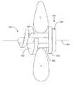
As can be seen, thespacer 120 can be teardrop-shaped in cross-section perpendicular to alongitudinal axis 125 of theimplant 100. In this way, the shape of thespacer 120 can roughly conform to a wedge-shaped space, or a portion of the space, between adjacent spinous processes within which theimplant 100 is to be positioned. As shown inFIG. 1A , the spacer120 (and the first wing108) is shaped to accommodate the anatomical form or contour of spinous processes (and/or laminae) of the C6 and C7 vertebrae for placement between such spinous processes (i.e., the C6-C7 motion segment). The same shape or variations of this shape can be used to accommodate other motion segments, for example in the thoracic or lumbar regions. In other embodiments thespacer 120 can have alternative shapes such as circular, wedge, oval, ovoid, football, and rectangular with rounded corners, and other shapes. The shape of thespacer 120 can be selected for a particular patient so that the physician can position theimplant 100 as close as possible to the anterior portion of the surface of the spinous process. The shape selected for thespacer 120 can affect the contact surface area of theimplant 100 and the spinous processes that are to be subject to distraction. Increasing the contact surface area between theimplant 100 and the spinous processes can distribute a load force between the spinous frame and theimplant 100.
Thefirst wing 130 is likewise teardrop-shaped in cross-section perpendicular to alongitudinal axis 125 of thespacer 120 anddistraction guide 110. The dimensions of thefirst wing 130 can be larger than that of thespacer 120, particularly along the axis of the spine, and can limit or block lateral displacement of theimplant 100 in the direction of insertion along thelongitudinal axis 125. As with thespacer 120, thefirst wing 130 can have other cross-sectional shapes, such as elliptical, wedge, circular, oval, ovoid, football, and rectangular with rounded corners and other shapes.
Theimplant 100 ofFIG. 1A further includes an adjustable wing160 (also referred to herein as a second wing) separate from thedistraction guide 110, thespacer 120 and thefirst wing 130. Thesecond wing 160 is connectable with the distraction guide110 (and/or the spacer120) once theimplant 100 is positioned between adjacent spinous processes. Thesecond wing 160, similar to thefirst wing 130, can limit or block lateral displacement of theimplant 100, however displacement is limited or blocked in the direction opposite insertion. When both thefirst wing 130 and thesecond wing 160 are connected with theimplant 100 and theimplant 100 is positioned between adjacent spinous processes, a portion of the spinous processes can be sandwiched between thefirst wing 130 and thesecond wing 160, limiting displacement along thelongitudinal axis 125. As can be seen, thesecond wing 160 can be teardrop-shaped in cross-section. Alip 180 defining aspace 170 through thesecond wing 160 allows thesecond wing 160 to pass over thedistraction guide 110 to meet and connect with thedistraction guide 110 and/or thespacer 120. Thesecond wing 160 is then secured to thedistraction guide 110 and/or thespacer 120. Thesecond wing 160, can be designed to be interference-fit onto thespacer 120 or a portion of thedistraction guide 110 adjacent to thespacer 120. Where thesecond wing 160 is interference-fit, there is no additional attachment device to fasten thesecond wing 160 relative to the remainder of theimplant 100.
Alternatively, various fasteners can be used to secure thesecond wing 160 relative to the remainder of theimplant 100. For example,FIG. 1A illustrates an embodiment of animplant 100 including a teardrop-shapedsecond wing 160 having atongue 158 at the posterior end of thesecond wing 160. Abore 155 is disposed through thetongue 158, and is aligned with acorresponding bore 156 on thespacer 120 when thesecond wing 160 is brought into position by surgical insertion relative to the rest of theimplant 100. A threadedscrew 154 can be inserted through the aligned bores155,156 in a posterior-anterior direction to secure thesecond wing 160 to thespacer 120. The direction of insertion from a posterior to an anterior direction has thescrew 154 engaging thebores implant 100 along a direction that is generally perpendicular to thelongitudinal axis 125. This orientation is most convenient when the physician is required to use ascrew 154 to secure thesecond wing 160 to the rest of theimplant 100. Thesecond wing 160 can further be secured to thespacer 120 by some other mechanism, for example such as a flexible hinge (not shown) with a protrusion that engages an indentation of one of thedistraction guide 110 and thespacer 120. Alternatively, thesecond wing 160 can be secured to one of thedistraction guide 110 and thespacer 120 by still some other mechanism.
Thedistraction guide 210 includes a tip from which thedistraction guide 210 expands, the tip having a diameter sufficiently small such that the tip can pierce an opening in an interspinous ligament and/or can be inserted into a small initial dilated opening. The diameter and/or cross-sectional area of thedistraction guide 210 gradually increases until it is substantially similar to the diameter of thespacer 220. The tapered front end eases the ability of a physician to urge theimplant 200 between adjacent spinous processes. When urging the main body of theimplant 200 between adjacent spinous processes, the front end of thedistraction guide 210 distracts the adjacent spinous processes and dilates the interspinous ligament so that a space between the adjacent spinous processes is approximately the diameter of thespacer 220.
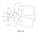
As shown inFIG. 1B , thespacer 220 is elliptically shaped in cross-section, and can swivel so that thespacer 220 can self-align relative to the uneven surfaces of the spinous processes. Self-alignment can ensure that compressive loads are distributed across the surface of the bone. As contemplated in Zucherman '842, thespacer 220 can have, for example, a diameter of six millimeters, eight millimeters, ten millimeters, twelve millimeters and fourteen millimeters. These diameters refer to the height by which thespacer 220 distracts and maintains apart the spinous process. For an elliptically shapedspacer 220, the selected height (i.e., diameter) is the minor dimension measurement across the ellipse. The major dimension is transverse to the alignment of the spinous process, one above the other.
Thefirst wing 230 has alower portion 231 and anupper portion 232. Theupper portion 232 is shaped to accommodate the anatomical form or contour of spinous processes (and/or laminae) of the L4 (for an L4-L5 placement) or L5 (for an L5-S1 placement) vertebra. The same shape or variations of this shape can be used to accommodate other motion segments, such as motion segments in the cervical and thoracic regions. Thelower portion 231 can also be rounded to accommodate the spinous processes. Thelower portion 231 andupper portion 232 of thefirst wing 230 act as a stop mechanism when theimplant 200 is inserted between adjacent spinous processes. Theimplant 200 cannot be inserted beyond the surfaces of thefirst wing 230. Additionally, once theimplant 200 is inserted, thefirst wing 230 can prevent some side-to-side, or posterior-to-anterior movement of theimplant 200.
As with theimplant 100 ofFIG. 1A , theimplant 200 ofFIG. 1B further includes asecond wing 260. Similar to thefirst wing 230, thesecond wing 260 includes alower portion 261 and anupper portion 262 sized and/or shaped to accommodate the anatomical form or contour of the spinous processes and/or lamina. Thesecond wing 260 can be secured to the main body of theimplant 200 with afastener 254. Thesecond wing 260 also has analignment tab 268. When thesecond wing 260 is initially placed on the main body of theimplant 200, thealignment tab 268 engages thealignment track 203. Thealignment tab 268 slides within thealignment track 203 and helps to maintain theadjustable wing 260 substantially parallel with thefirst wing 230. When the main body of theimplant 200 is inserted into the patient and thesecond wing 260 has been attached, displacement along thelongitudinal axis 225 in either the direction of insertion or the direction opposite insertion can be limited or blocked. Further, thesecond wing 260 also can prevent some side-to-side, or posterior-to-anterior movement.
For both theimplant 100 ofFIG. 1A and theimplant 200 ofFIG. 1B , where asecond wing implant implant implant second wing implant implant first wing second wing second wing
Implants Having a Lead-In Screw
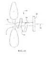
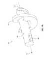
Referring toFIGS. 2A through 3C ,implants 300 and methods for positioning such implants in accordance with the present invention can include, in an embodiment, aframe 302 having acentral body 304 extending along alongitudinal axis 325 of theimplant 300. Thecentral body 304 can include adistraction guide 306 at a proximal end of thecentral body 304. Thedistraction guide 306 can have a tapered shape so that thedistraction guide 306 can pierce and/or distract an interspinous ligament associated with the targeted motion segment. Afirst wing 330 extends from a distal end of thecentral body 304 and acts to limit or block movement of theimplant 300 along thelongitudinal axis 325 in the direction of insertion.
A substantially thread-shaped lead-in screw (also referred to herein as a second wing)360 extends from the periphery of thecentral body 304 distally located relative to thedistraction guide 306. For example, the second wing can be helically shaped, wherein a helical shape is generally a three-dimensional curve that lies on a cylinder or a cone, so that its angle to a plane perpendicular to the axis is constant. Helical shapes as described herein need not lie along a constant angle, but rather can lie along an angle that varies. A helical shape need only include a curve that has a gap361 (also referred to herein as a groove) between overlapping surfaces such that structures related to the adjacent spinous processes and the spinous processes can pass within thegroove 361. It is to be understood that a lead-in screw shape other than helical is within the spirit and scope of the invention. For example, a shape with a constant diameter thread, or with different or constant thread pitches can be used. Generally and preferably thesecond wing 360 can have an outer diameter that steadily increases from near the proximal end of thecentral body 304 distally toward thefirst wing 330. Thesecond wing 360 terminates so that a spacer320 (FIG. 2B ) can be arranged between thesecond wing 360 and thefirst wing 330. The helical shape of thesecond wing 360 can facilitate implantation between adjacentspinous processes 2,4 (shown inFIGS. 3A-3E ) from one or more incisions formed on one side of an interspinous ligament6 extending between the adjacentspinous processes
Implantation can be accomplished in such embodiments as described above by initially piercing or distracting the interspinous ligament6 with thedistraction guide 306, and subsequently rotating thecentral body 304. One or both of the interspinous ligament6 and the adjacentspinous processes groove 361 of the helically shapedsecond wing 360 as thecentral body 304 is rotated and thecentral body 304 is drawn or urged along thelongitudinal axis 325 in the direction of insertion. The interspinous ligament6 and/or associatedspinous processes groove 361 and therefore along thecentral body 304, causing thesecond wing 360 to be positioned, when theimplant 300 is seated, at an opposite side of the interspinous ligament6 from thefirst wing 330 such that the interspinous ligament6 is disposed between thefirst wing 330 and thesecond wing 360 along thelongitudinal axis 325. Arranging the interspinous ligament6, and/or the associatedspinous processes first wing 330 and thesecond wing 360 limits or blocks movement along thelongitudinal axis 325.
In some embodiments, thedistraction guide 306 can have a generally conical shape, rather than a wedge-shape as described above in reference toFIGS. 1A and 1B . Where thedistraction guide 306 includes a wedge-shape, rotation of thecentral body 304 can cause thedistraction guide 306 to distract the adjacentspinous processes distraction guide 306.
Referring toFIG. 2A , as with thedistraction guide 306, thefirst wing 330 has a rounded shape, having substantially the same minor and major dimension. Thefirst wing 330 is shaped so that thefirst wing 330 can rotate along with thecentral body 304 while minifying interference from surrounding structures. Further, the rounded shape of thefirst wing 330 can accommodate slots as described below, while providing a surface to contact the adjacentspinous processes longitudinal axis 325 in the direction of insertion. However, in other embodiments, thefirst wing 330 need not have a rounded shape.
Thefirst wing 330 can include one or more slots to receive aspacer 320 so that thespacer 320 can be arranged over thecentral body 304 between thesecond wing 360 and thefirst wing 330. As shown, thefirst wing 330 includes twoslots slots spacer 320. Theslots central body 304, so that when aspacer 320 is urged through theslots spacer 320 abuts thecentral body 304, thereby allowing a portion of a load to be transferred to thecentral body 304. In other embodiments, one or more slots can be disposed through thefirst wing 330 and can be shaped as desired, such that the one or more slots having the same or different geometries.
As can be seen, thetop portion 322 and thebottom portion 324 include respective lead-intissue expanders 321,323 (also referred to herein as distraction guides). The distraction guides321,323 for thetop portion 322 and thebottom portion 324 can taper at the proximal end of thespacer 320, thereby allowing thedistraction guide 306 to distract one or both of the adjacentspinous processes
As can be seen, thetop portion 322 and thebottom portion 324, taken together in cross-section perpendicular to alongitudinal axis 325, can have a split teardrop shape, similar to a cross-section of thespacer 120 ofFIG. 1A . In this way, the shape of thespacer 320 can roughly conform to a wedge-shaped space, or a portion of the space, between adjacent spinous processes within which theimplant 300 is to be positioned. The same shape or variations of this shape can be used to accommodate different motion segments and/or different patients, as described above. In other embodiments thespacer 320 can have alternative shapes such as circular, elliptical, wedge, oval, ovoid, football, and rectangular with rounded corners, and other shapes. The shape of thespacer 320 can be selected for a particular patient so that the physician can position theimplant 300 as close as possible to the anterior portion of the surface of the spinous process. The shape selected for thespacer 320 can affect the contact surface area of theimplant 300 and the spinous processes that are to be subject to distraction. Increasing the contact surface area between theimplant 300 and the spinous processes can distribute a load force between the spinous frame and theimplant 300.
Thetop portion 322 and thebottom portion 324 extend from abase 326 and are fixed in relative position by thebase 326. As can be seen, thebottom portion 324 extends farther than thetop portion 322. As will be described in further detail below, thetop portion 322 is truncated in length along thelongitudinal axis 325 relative to thebottom portion 324 to avoid contacting thesecond wing 360 which in the embodiment shown inFIG. 2A spirals to a termination point at the upper surface of thecentral body 304. An additional advantage with the truncatedtop portion 322 is that the spinous processes are distracted more gradually, first with thebottom portion 324 and then with thetop portion 322 as thespacer 320 is inserted into theframe 302. The base326 can have a length along thelongitudinal axis 325 as desired, and preferably having a length sufficient to support thetop portion 322 and thebottom portion 324 in an at least semi-rigid position relative to one another. The base326 can include acavity 329 for receiving one or both of an insertion tool and a fastener (not shown). Thecavity 329 can correspond to a threadedcavity 309 disposed in thecentral body 304 so that, for example, theframe 302 and thespacer 320 can be fixedly attached, with by way of example only a screw, once thespacer 320 is seated.
Referring toFIGS. 3D and 3E , once theframe 304 is arranged as desired, thetop portion 322 and thebottom portion 324 can be positioned within the correspondingslots central body 304 so that thetop portion 322 andbottom portion 324 further distract the interspinous ligament6 and/or the adjacentspinous processes spacer 320 can be urged in the direction of insertion until thebase 326 is seated against thefirst wing 330. In a preferred embodiment, thetop portion 322 and thebottom portion 324 can be arranged so that thetop portion 322 andbottom portion 324 are approximately in contact or near-contact with thesecond wing 360, so that thespacer 320 fully supports a load applied by the adjacentspinous processes
As can further be seen, the base326 can include acavity 329 that in an embodiment is a bore having a diameter larger than a diameter of acorresponding cavity 309 of thefirst wing 330. Such a feature can be receive an insertion tool (not shown) for assisting in implantation, or such a feature can receive a fastener (not shown), such as a screw or bolt to secure thespacer 320 to theframe 302. Abore 329 having a larger diameter than thecavity 309 of theframe 302 can allow a head of the fastener to be received so that the head does not extend beyond a distal face of thebase 326. In other embodiments, the base326 can include one or more additional cavities for receiving lock pins, or other features of an insertion tool (not shown), for example as described in U.S. Pat. No. 6,712,819, entitled “Mating Insertion Instruments for Spinal Implants and Methods of Use,” issued Mar. 30, 2004 to Zucherman, et al.
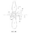
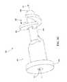
Referring now toFIGS. 5A through 5C , an alternative embodiment of animplant 400 in accordance with an embodiment of the present invention is shown.FIG. 5A is a perspective view of theframe 402 including acentral body 404 having adistraction guide 406 at a proximal end, and analignment protrusion 408 at a distal end. As can be seen, thesecond wing 460 is similar to thesecond wing 460 described above. Thealignment protrusion 408 extends from thecentral body 404 to align aspacer 420 as thespacer 420 is arranged over thecentral body 404, and to prevent thespacer 420 from subsequently rotating relative to theframe 402 once implanted. Thus, thealignment protrusion 408 corresponds to a notch427 within thespacer 420 within which thecentral body 404 is partially disposed.
As above, thespacer 420 can have a cross-section perpendicular to thelongitudinal axis 425 that is teardrop-shaped, similar to a cross-section of thespacer FIGS. 1A and 2A . In this way, the shape of thespacer 420 can roughly conform to a wedge-shaped space, or a portion of the space, between adjacentspinous processes implant 400 is to be positioned. The same shape or variations of this shape can be used to accommodate different motion segments and/or different patients, as described above. In other embodiments thespacer 420 can have alternative shapes such as circular, elliptical, wedge, oval, ovoid, football, and rectangular with rounded corners, and other shapes. The shape of thespacer 420 can be selected for a particular patient so that the physician can position theimplant 400 as close as possible to the anterior portion of the surface of thespinous process spacer 420 can affect the contact surface area of theimplant 400 and thespinous processes implant 400 and thespinous processes implant 400.
Thespacer 420 ofFIG. 5B extends from afirst wing 430 integrally formed or connected with thespacer 420. As can be seen, a proximal end of thespacer 420 varies in length, extending farther near the bottom section of thespacer 420 to correspond roughly with the helical shape of thesecond wing 460, thereby avoiding contacting thesecond wing 460 which in the embodiment shown inFIG. 5A spirals to a termination point at the upper surface of thecentral body 404. As above, once theframe 404 is arranged as desired, thespacer 420 can be positioned over thecentral body 404 and urged over thecentral body 404 so that thespacer 420 further distracts the interspinous ligament and/or the adjacent spinous processes. Thespacer 320 can be urged in the direction of insertion until thecentral body 404 is seated within thebore 428. In a preferred embodiment, the shape of the proximal end of thespacer 420 is shaped such that when seated, the proximal end is approximately in contact or near-contact with thesecond wing 460, so that thespacer 420 fully supports a load applied by the adjacent spinous processes, without slippage.
Thefirst wing 430 can have a depth along thelongitudinal axis 425 as desired, and a width such that thefirst wing 430 can contact one or both of the adjacentspinous processes implant 400 in the direction of insertion along thelongitudinal axis 425. As shown, thefirst wing 430 has a rounded shape, having substantially the same minor and major dimension. Unlike the embodiment of theimplant 300 ofFIGS. 2A-2C , thefirst wing 430 need not rotate to properly arrange thesecond wing 460, therefore thefirst wing 430 need not have a round shape, where it is desired that thesecond wing 460 have some other shape. For example, thefirst wing 430 can include a shape similar to that shown inFIG. 1B . Thefirst wing 430 can include a cavity429 for receiving one or both of an insertion tool (not shown). Further, thecentral body 404 can optionally include a cavity409 so that, for example, theframe 402, thespacer 420, and thefirst wing 430 can be fixedly attached once thespacer 420 is seated.
In some embodiments ofsystems including implants FIGS. 2A-5C , multipledifferent spacers single frame spacer central body 304 extending from afirst wing 330, the distance between the outer peripheries of the twoslots central body 404 having analignment protrusion 408, a series ofspacer 420 can have varying dimensions and/or shapes, and can have similarlysized cavities 428 to receive thecentral body 404. As can be readily understood from this description, a system in accordance with embodiments of the present invention can include aframe spacers
As mentioned above, implants, and systems and methods for positioning such implants between spinous processes in accordance with the present invention are not meant to be limited to embodiments as described above and otherwise herein, but rather are meant to include all such implants that utilize a wing having a major dimension larger than a major dimension of a space between spinous processes, wherein the wing can be appropriately positioned by rotating the implant while urging the implant in a direction of insertion. Myriad different variations may be readily apparent to one of ordinary skill in the art. For example, as shown inFIGS. 7A through 7C , in still another embodiment of an implant500 in accordance with the present invention, theframe 502 can include an innercentral body 504 disposed within an outercentral body 505, with a proximal portion of asecond wing 560 being connected with, or extending from the innercentral body 504, and the distal portion of thesecond wing 560 being connected with, or extending from the outercentral body 505. Once theframe 502 is arranged as desired, such that the interspinous ligament is disposed between afirst wing 330 and thesecond wing 560, the innercentral body 504 can be shifted to a position more fully received in the outercentral body 505 so that thesecond wing 560 collapses, reducing the space occupied by thesecond wing 560.
In such embodiments as shown inFIGS. 7A through 7C , thesecond wing 560 can be made from a more ductile material so that thesecond wing 560 can be readily collapsed. Alternatively, thesecond wing 560 can be made from a shape memory material, for example such as Nitinol, so that once the frame is positioned thesecond wing 560 collapses, urging the innercentral body 504 to shift within the outercentral body 505. Additionally thesecond wing 560 can be made in two parts, one part fastened to the innercentral body 504, and one part fastened to the outercentral body 505. When the innercentral body 504 is more fully received into the outercentral body 505, the portion of thesecond wing 560 secure to the innercentral body 504 becomes nested in the portion of thesecond wing 560 connected to the outercentral body 505.
As shown inFIG. 8 , in a still further embodiment an implant600 in accordance with the present invention can include adistraction guide 606 that tapers more gradually, so that the adjacent spinous processes and/or related tissues are distracted as the lead-inscrew 660 is rotated and urged toward a direction of insertion, as described above.
In still further embodiments, the spacer need not be fixed, but rather can be rotatably disposed over the central body. For example, the spacer can include an alignment notch, as described above with reference toFIG. 1B , so that when the central body is rotated, thereby threading the adjacent spinous processes and related structures within the groove of the thread-shaped wing and positioning the thread-shaped wing on an opposite side of the adjacent spinous processes, the spacer can be held in a fixed position. By fixing the spacer in position, the spacer can be arranged as desired between the adjacent spinous processes. Once the implant is positioned between adjacent spinous processes, the rotatable spacer can be released to conform within the space between spinous processes. These and other variations are within the scope of the invention as contemplated.
Materials for use in Implants of the Present Invention
In some embodiments, the implant, and components of the implant (i.e., the spacer, the frame) can be fabricated from medical grade metals such as titanium, stainless steel, cobalt chrome, and alloys thereof, or other suitable implant material having similar high strength and biocompatible properties. Additionally, the implant can be at least partially fabricated from a shape memory metal, for example Nitinol, which is a combination of titanium and nickel. Such materials are typically radiopaque, and appear during x-ray imaging, and other types of imaging. Implants in accordance with the present invention, and/or portions thereof can also be fabricated from somewhat flexible and/or deflectable material. In these embodiments, the implant and/or portions thereof can be fabricated in whole or in part from medical grade biocompatible polymers, copolymers, blends, and composites of polymers. A copolymer is a polymer derived from more than one species of monomer. A polymer composite is a heterogeneous combination of two or more materials, wherein the constituents are not miscible, and therefore exhibit an interface between one another. A polymer blend is a macroscopically homogeneous mixture of two or more different species of polymer. Many polymers, copolymers, blends, and composites of polymers are radiolucent and do not appear during x-ray or other types of imaging. Implants comprising such materials can provide a physician with a less obstructed view of the spine under imaging, than with an implant comprising radiopaque materials entirely. However, the implant need not comprise any radiolucent materials.
One group of biocompatible polymers is the polyaryletherketone group which has several members including polyetheretherketone (PEEK), and polyetherketoneketone (PEKK). PEEK is proven as a durable material for implants, and meets the criterion of biocompatibility. Medical grade PEEK is available from Victrex Corporation of Lancashire, Great Britain under the product name PEEK-OPTIMA. Medical grade PEKK is available from Oxford Performance Materials under the name OXPEKK, and also from CoorsTek under the name BioPEKK. These medical grade materials are also available as reinforced polymer resins, such reinforced resins displaying even greater material strength. In an embodiment, the implant can be fabricated from PEEK 450G, which is an unfilled PEEK approved for medical implantation available from Victrex. Other sources of this material include Gharda located in Panoli, India. PEEK 450G has the following approximate properties:
| Property | Value | ||
| Density | 1.3 | g/cc | ||
| Rockwell M | 99 | |||
| Rockwell R | 126 | |||
| Tensile Strength | 97 | MPa | ||
| Modulus of Elasticity | 3.5 | GPa | ||
| Flexural Modulus | 4.1 | GPa | ||
PEEK 450G has appropriate physical and mechanical properties and is suitable for carrying and spreading a physical load between the adjacent spinous processes. The implant and/or portions thereof can be formed by extrusion, injection, compression molding and/or machining techniques.
It should be noted that the material selected can also be filled. Fillers can be added to a polymer, copolymer, polymer blend, or polymer composite to reinforce a polymeric material. Fillers are added to modify properties such as mechanical, optical, and thermal properties. For example, carbon fibers can be added to reinforce polymers mechanically to enhance strength for certain uses, such as for load bearing devices. In some embodiments, other grades of PEEK are available and contemplated for use in implants in accordance with the present invention, such as 30% glass-filled or 30% carbon-filled grades, provided such materials are cleared for use in implantable devices by the FDA, or other regulatory body. Glass-filled PEEK reduces the expansion rate and increases the flexural modulus of PEEK relative to unfilled PEEK. The resulting product is known to be ideal for improved strength, stiffness, or stability. Carbon-filled PEEK is known to have enhanced compressive strength and stiffness, and a lower expansion rate relative to unfilled PEEK. Carbon-filled PEEK also offers wear resistance and load carrying capability.
As will be appreciated, other suitable similarly biocompatible thermoplastic or thermoplastic polycondensate materials that resist fatigue, have good memory, are flexible, and/or deflectable, have very low moisture absorption, and good wear and/or abrasion resistance, can be used without departing from the scope of the invention. As mentioned, the implant can be comprised of polyetherketoneketone (PEKK). Other material that can be used include polyetherketone (PEK), polyetherketoneetherketoneketone (PEKEKK), polyetheretherketoneketone (PEEKK), and generally a polyaryletheretherketone. Further, other polyketones can be used as well as other thermoplastics. Reference to appropriate polymers that can be used in the implant can be made to the following documents, all of which are incorporated herein by reference. These documents include: PCT Publication WO 02/02158 A1, dated Jan. 10, 2002, entitled “Bio-Compatible Polymeric Materials;” PCT Publication WO 02/00275 A1, dated Jan. 3, 2002, entitled “Bio-Compatible Polymeric Materials;” and, PCT Publication WO 02/00270 A1, dated Jan. 3, 2002, entitled “Bio-Compatible Polymeric Materials.” Other materials such as Bionate®, polycarbonate urethane, available from the Polymer Technology Group, Berkeley, Calif., may also be appropriate because of the good oxidative stability, biocompatibility, mechanical strength and abrasion resistance. Other thermoplastic materials and other high molecular weight polymers can be used.
Methods for Implanting Interspinous Implants
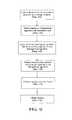
A minimally invasive surgical method for implanting animplant 300 in the cervical spine is disclosed and taught herein. In this method, as shown inFIG. 9 , preferably aguide wire 680 is inserted through aplacement network 690 into the neck of the implant recipient. Theguide wire 680 is used to locate where theimplant 300 is to be placed relative to the cervical spine, including the spinous processes. Once theguide wire 680 is positioned with the aid of imaging techniques, an incision is made on the side of the neck so that animplant 300 in accordance with an embodiment of the present invention, can be positioned in the neck thorough an incision and along a line that is about perpendicular to theguide wire 680 and directed at the end of theguide wire 680. Aframe 302 of theimplant 300 is inserted into the neck of the patient. Theframe 302 includes adistraction guide 306 extending from the proximal end of acentral body 304 and afirst wing 330 extending from the distal end of thecentral body 304. Theframe 302 further includes a helical-shapedsecond wing 360 extending distally from thedistraction guide 306 some distance along thecentral body 304. Preferably during insertion, thedistraction guide 306 pierces or separates the tissue without severing the tissue. Theframe 302 can be arranged so that thesecond wing 360 extending from thecentral body 304 is in contact or near contact with the interspinous ligament. Theframe 302 is then rotated in a direction so that the spiraling extension of thesecond wing 360 “grows” and theframe 302 is urged forward such that the adjacent spinous processes fit within a groove between spiraled surfaces of thesecond wing 360. Theframe 302 is continuously rotated until thesecond wing 360 has passed the adjacentspinous processes
Theframe 302 can be further rotated untilslots first wing 330 are arranged as desired between the adjacentspinous processes frame 302 is satisfactorily positioned, aspacer 320 can be mated with theframe 302 so that anupper portion 322 and alower portion 324 of thespacer 320 is received through therespective slot central body 304 for example where thefirst wing 330 extends from thespacer 320 rather than extending form the central body304). Thespacer 320 can be inserted along a line that is generally colinear with the line over which theframe 302 is inserted. The anatomy of the neck is such that it is most convenient and minimally invasive to enter the neck from the side with respect to theframe 302 and thespacer 320.
Further, a minimally invasive surgical method for implanting animplant 300 in the lumbar spine is disclosed and taught herein. In this method, as shown in the flowchart ofFIG. 10 , preferably a unilateral incision can be made using a posterior-anterior approach. The unilateral incision can be made, for example, at a location some distance to the right of an axis along thespinous process 2,4 (Step102). The incision can be enlarged, and a distraction tool can be positioned within the incision so that the proximal end of the distraction tool can access an exposed side of the interspinous ligament6. The distraction tool can be urged through the interspinous ligament6 and distracted, thereby distracting the interspinous ligament6 so as to receive the implant300 (Step104). Once the interspinous ligament6 is sufficiently distracted, the distraction tool can be disengaged and removed from the incision.
Once the distraction tool has been removed from the incision, theframe 302 can be positioned at the dilated opening, and thedistraction guide 306 of theframe 302 can be urged through the dilated opening (Step106). As above, theframe 302 can be arranged so that thesecond wing 360 extending from thecentral body 304 is in near contact with the interspinous ligament6. Theframe 302 is then rotated in direction so that the spiraling extension of thesecond wing 360 “grows”, and theframe 302 urged forward such that the adjacentspinous processes frame 302 is continuously rotated until thesecond wing 360 has passed the adjacentspinous processes
Theframe 300 can be further rotated until theslots frame 302 is free to rotate so that the load can be distributed more evenly over the surface of the spinous processes. Once theframe 302 is satisfactorily positioned, aspacer 320 can be inserted withslots first wing 330 extending from the distal end of the central body304 (or simply received over the central body for example where the first wing extends from the spacer). Thespacer 320 can be inserted along a line that is generally colinear with the line over which theframe 302 is inserted (Step110). The remaining tools can be removed from the incision, and the incision can be closed. Preferably during insertion, the distraction end pierces or separates the tissue without severing the tissue (Step112).
The foregoing description of the present invention have been presented for purposes of illustration and description. It is not intended to be exhaustive or to limit the invention to the precise forms disclosed. Many modifications and variations will be apparent to practitioners skilled in this art. The embodiments were chosen and described in order to best explain the principles of the invention and its practical application, thereby enabling others skilled in the art to understand the invention for various embodiments and with various modifications as are suited to the particular use contemplated. It is intended that the scope of the invention be defined by the following claims and their equivalents.
Claims (19)
1. A spinal implant adapted to be inserted into an interspinous space between adjacent spinous processes, comprising:
a proximal section, a central section, and a distal section disposed sequentially along a longitudinal axis, the central section includes a top section and a bottom section;
the distal section having a thread-like structure spiraling about a portion of the distal section such that the top section of the central portion is non-threaded a distance shorter than the bottom section of the central portion, the thread-like structure defining an outermost portion thereof relative to the longitudinal axis, such that the outermost portion is configured to engage the spinous process to limit movement of the implant;
the distal section terminating in a distal tip disposed distally of the thread-like structure and defining a distal-most portion of the implant;
the distal tip tapering inward in a distal direction;
the central section sized and configured to engage the adjacent spinous processes when the implant is disposed through the interspinous space between the adjacent spinous processes; and
the proximal section having a wing that extends farther outward relative to the longitudinal axis than all portions of the central section.
2. The implant ofclaim 1 wherein the distal tip is rounded.
3. The implant ofclaim 1 wherein the distal section includes a first portion movable between an expanded configuration and a collapsed configuration; the first portion disposed proximally of the distal tip.
4. The implant ofclaim 1 wherein the implant comprises Nitinol and a biocompatible polymer.
5. The implant ofclaim 4 wherein the biocompatible polymer is PEEK.
6. The implant ofclaim 1 wherein the thread-like structure extends a constant distance from the longitudinal axis.
7. The implant ofclaim 1 wherein the thread-like structure is helical.
8. The implant ofclaim 1 wherein the implant includes a longitudinally extending cavity.
9. The implant ofclaim 1 wherein the implant comprises a main body that includes the wing and a spacer slidably mated to the main body through the wing.
10. The implant ofclaim 9 , wherein the spacer includes a top portion and a bottom portion being longer than the top portion such that the bottom portion of the spacer fits into the non-threaded bottom section of the central portion and the top portion fits into the non-threaded top section of the central portion.
11. The implant ofclaim 1 wherein the thread-like structure is adapted to guide the implant between the spinous processes so that the implant is selectively disposed through the interspinous space.
12. A spinal implant adapted to be inserted into an interspinous space between adjacent spinous processes, comprising:
a proximal section, a central section, and a distal section disposed sequentially along a longitudinal axis, the central section includes a top section and a bottom section;
the distal section having an external helical groove spiraling about a portion of the distal section such that the top section of the central portion includes a flat surface shorter than a flat surface of the bottom section of the central portion;
the distal section terminating in a distal tip disposed distally of the groove and defining a distal-most portion of the implant;
the distal tip tapering inward in a distal direction;
the proximal section having a flange that extends farther outward relative to the longitudinal axis than all portions of the central section; wherein the flange is sized and configured to limit distal displacement of the implant when the implant is disposed through the interspinous space between the adjacent spinous processes;
wherein the distal section includes a first portion movable between an expanded configuration and a collapsed configuration;
the first portion disposed proximally of the distal tip;
wherein the first portion, in the expanded configuration, is sized and configured to limit proximal displacement of the implant when the implant is disposed through the interspinous space between the adjacent spinous processes; and
wherein the distal section, when the first portion is in the expanded configuration, extends farther outward from the longitudinal axis than all portions of the central section.
13. The implant ofclaim 12 wherein the distal tip is rounded.
14. The implant ofclaim 12 wherein the groove has a constant depth.
15. The implant ofclaim 12 wherein the implant includes a longitudinally extending cavity.
16. The implant ofclaim 12 wherein the implant comprises a main body that includes the flange and a spacer slidably mated to the main body through the flange.
17. The implant ofclaim 16 , wherein the spacer includes a top portion and a bottom portion being longer than the top portion of the spacer such that the bottom portion of the spacer fits into the flat surface of the bottom section of the central section and the top portion fits into the flat surface of the top section of the central section.
18. The implant ofclaim 12 wherein a portion of the distal section disposed proximal to the distal tip, and comprising the groove, is adapted to guide the implant between the spinous processes so that the implant is selectively disposed through the interspinous space.
19. A spinal implant adapted to be inserted into an interspinous space between adjacent spinous processes, comprising:
a proximal section, a central section, a main body and a distal section disposed sequentially along a longitudinal axis;
the distal section having a thread-like structure defining an outermost portion thereof relative to the longitudinal axis;
the distal section terminating in a distal tip disposed distally of the thread-like structure and defining a distal-most portion of the implant;
the distal tip tapering inward in a distal direction; the central section sized and configured to engage the adjacent spinous processes when the implant is disposed through the interspinous space between the adjacent spinous processes;
the proximal section having a wing that extends farther outward relative to the longitudinal axis than all portions of the central section; and
a spacer slidably mated to the main body through the wing.
Priority Applications (1)
| Application Number | Priority Date | Filing Date | Title |
|---|---|---|---|
| US13/313,391US8591546B2 (en) | 2005-03-21 | 2011-12-07 | Interspinous process implant having a thread-shaped wing and method of implantation |
Applications Claiming Priority (3)
| Application Number | Priority Date | Filing Date | Title |
|---|---|---|---|
| US66392205P | 2005-03-21 | 2005-03-21 | |
| US11/378,892US8147548B2 (en) | 2005-03-21 | 2006-03-17 | Interspinous process implant having a thread-shaped wing and method of implantation |
| US13/313,391US8591546B2 (en) | 2005-03-21 | 2011-12-07 | Interspinous process implant having a thread-shaped wing and method of implantation |
Related Parent Applications (1)
| Application Number | Title | Priority Date | Filing Date |
|---|---|---|---|
| US11/378,892ContinuationUS8147548B2 (en) | 2002-10-29 | 2006-03-17 | Interspinous process implant having a thread-shaped wing and method of implantation |
Publications (2)
| Publication Number | Publication Date |
|---|---|
| US20120083843A1 US20120083843A1 (en) | 2012-04-05 |
| US8591546B2true US8591546B2 (en) | 2013-11-26 |
Family
ID=37024163
Family Applications (3)
| Application Number | Title | Priority Date | Filing Date |
|---|---|---|---|
| US11/378,892Active2029-11-12US8147548B2 (en) | 2002-10-29 | 2006-03-17 | Interspinous process implant having a thread-shaped wing and method of implantation |
| US11/923,738Active2029-12-16US8273107B2 (en) | 2005-03-21 | 2007-10-25 | Interspinous process implant having a thread-shaped wing and method of implantation |
| US13/313,391Active2026-05-05US8591546B2 (en) | 2005-03-21 | 2011-12-07 | Interspinous process implant having a thread-shaped wing and method of implantation |
Family Applications Before (2)
| Application Number | Title | Priority Date | Filing Date |
|---|---|---|---|
| US11/378,892Active2029-11-12US8147548B2 (en) | 2002-10-29 | 2006-03-17 | Interspinous process implant having a thread-shaped wing and method of implantation |
| US11/923,738Active2029-12-16US8273107B2 (en) | 2005-03-21 | 2007-10-25 | Interspinous process implant having a thread-shaped wing and method of implantation |
Country Status (7)
| Country | Link |
|---|---|
| US (3) | US8147548B2 (en) |
| EP (1) | EP1868537B1 (en) |
| JP (1) | JP4861404B2 (en) |
| KR (1) | KR20080040619A (en) |
| CN (1) | CN101146495B (en) |
| AU (1) | AU2006227004B2 (en) |
| WO (1) | WO2006102428A1 (en) |
Families Citing this family (71)
| Publication number | Priority date | Publication date | Assignee | Title |
|---|---|---|---|---|
| US7763074B2 (en) | 2004-10-20 | 2010-07-27 | The Board Of Trustees Of The Leland Stanford Junior University | Systems and methods for posterior dynamic stabilization of the spine |
| US8277488B2 (en) | 2004-10-20 | 2012-10-02 | Vertiflex, Inc. | Interspinous spacer |
| US9119680B2 (en) | 2004-10-20 | 2015-09-01 | Vertiflex, Inc. | Interspinous spacer |
| US8273108B2 (en) | 2004-10-20 | 2012-09-25 | Vertiflex, Inc. | Interspinous spacer |
| US8613747B2 (en) | 2004-10-20 | 2013-12-24 | Vertiflex, Inc. | Spacer insertion instrument |
| US9023084B2 (en) | 2004-10-20 | 2015-05-05 | The Board Of Trustees Of The Leland Stanford Junior University | Systems and methods for stabilizing the motion or adjusting the position of the spine |
| US8167944B2 (en) | 2004-10-20 | 2012-05-01 | The Board Of Trustees Of The Leland Stanford Junior University | Systems and methods for posterior dynamic stabilization of the spine |
| US8945183B2 (en) | 2004-10-20 | 2015-02-03 | Vertiflex, Inc. | Interspinous process spacer instrument system with deployment indicator |
| US9161783B2 (en) | 2004-10-20 | 2015-10-20 | Vertiflex, Inc. | Interspinous spacer |
| US8128662B2 (en) | 2004-10-20 | 2012-03-06 | Vertiflex, Inc. | Minimally invasive tooling for delivery of interspinous spacer |
| US8317864B2 (en) | 2004-10-20 | 2012-11-27 | The Board Of Trustees Of The Leland Stanford Junior University | Systems and methods for posterior dynamic stabilization of the spine |
| US8409282B2 (en) | 2004-10-20 | 2013-04-02 | Vertiflex, Inc. | Systems and methods for posterior dynamic stabilization of the spine |
| US8425559B2 (en) | 2004-10-20 | 2013-04-23 | Vertiflex, Inc. | Systems and methods for posterior dynamic stabilization of the spine |
| US8012207B2 (en) | 2004-10-20 | 2011-09-06 | Vertiflex, Inc. | Systems and methods for posterior dynamic stabilization of the spine |
| US8123807B2 (en) | 2004-10-20 | 2012-02-28 | Vertiflex, Inc. | Systems and methods for posterior dynamic stabilization of the spine |
| US8152837B2 (en) | 2004-10-20 | 2012-04-10 | The Board Of Trustees Of The Leland Stanford Junior University | Systems and methods for posterior dynamic stabilization of the spine |
| US8123782B2 (en) | 2004-10-20 | 2012-02-28 | Vertiflex, Inc. | Interspinous spacer |
| US9055981B2 (en) | 2004-10-25 | 2015-06-16 | Lanx, Inc. | Spinal implants and methods |
| US8241330B2 (en) | 2007-01-11 | 2012-08-14 | Lanx, Inc. | Spinous process implants and associated methods |
| EP2219538B1 (en) | 2004-12-06 | 2022-07-06 | Vertiflex, Inc. | Spacer insertion instrument |
| US8221462B2 (en)* | 2005-08-01 | 2012-07-17 | Globus Medical, Inc. | Interspinous internal fixation/distraction device |
| JP4797174B2 (en)* | 2005-08-11 | 2011-10-19 | 国立大学法人神戸大学 | A minimally invasive implant for the purpose of enlargement between spinous processes and a method for percutaneously expanding between spinous processes using the same |
| PL377136A1 (en) | 2005-09-19 | 2007-04-02 | Lfc Spółka Z Ograniczoną Odpowiedzialnością | Intervertebral space implant |
| WO2007087535A2 (en)* | 2006-01-23 | 2007-08-02 | Pioneer Surgical Technology, Inc. | Interlaminar stabilizing system |
| GB0605960D0 (en)* | 2006-03-24 | 2006-05-03 | Galley Geoffrey H | Expandable spinal prosthesis |
| US8845726B2 (en) | 2006-10-18 | 2014-09-30 | Vertiflex, Inc. | Dilator |
| US9265532B2 (en) | 2007-01-11 | 2016-02-23 | Lanx, Inc. | Interspinous implants and methods |
| US9247968B2 (en) | 2007-01-11 | 2016-02-02 | Lanx, Inc. | Spinous process implants and associated methods |
| WO2008098054A2 (en) | 2007-02-06 | 2008-08-14 | Pioneer Surgical Technology, Inc. | Intervertebral implant devices and methods for insertion thereof |
| US7842074B2 (en) | 2007-02-26 | 2010-11-30 | Abdou M Samy | Spinal stabilization systems and methods of use |
| US9545267B2 (en)* | 2007-03-26 | 2017-01-17 | Globus Medical, Inc. | Lateral spinous process spacer |
| AU2008241447B2 (en) | 2007-04-16 | 2014-03-27 | Vertiflex, Inc. | Interspinous spacer |
| US8142479B2 (en) | 2007-05-01 | 2012-03-27 | Spinal Simplicity Llc | Interspinous process implants having deployable engagement arms |
| US8070779B2 (en)* | 2007-06-04 | 2011-12-06 | K2M, Inc. | Percutaneous interspinous process device and method |
| US8308767B2 (en) | 2007-09-19 | 2012-11-13 | Pioneer Surgical Technology, Inc. | Interlaminar stabilization system |
| US20090118833A1 (en)* | 2007-11-05 | 2009-05-07 | Zimmer Spine, Inc. | In-situ curable interspinous process spacer |
| AU2009206098B2 (en) | 2008-01-15 | 2014-10-30 | Vertiflex, Inc. | Interspinous spacer |
| US8252029B2 (en)* | 2008-02-21 | 2012-08-28 | Zimmer Gmbh | Expandable interspinous process spacer with lateral support and method for implantation |
| US8523910B2 (en)* | 2008-04-22 | 2013-09-03 | Globus Medical, Inc. | Lateral spinous process spacer |
| US8192466B2 (en)* | 2008-08-27 | 2012-06-05 | Alphatec Spine, Inc. | Conical interspinous apparatus and a method of performing interspinous distraction |
| US8172878B2 (en)* | 2008-08-27 | 2012-05-08 | Yue James J | Conical interspinous apparatus and a method of performing interspinous distraction |
| WO2010045491A1 (en)* | 2008-10-15 | 2010-04-22 | Replication Medical, Inc. | Swellable interspinous stabilization implant |
| US9861399B2 (en) | 2009-03-13 | 2018-01-09 | Spinal Simplicity, Llc | Interspinous process implant having a body with a removable end portion |
| US8945184B2 (en)* | 2009-03-13 | 2015-02-03 | Spinal Simplicity Llc. | Interspinous process implant and fusion cage spacer |
| US9757164B2 (en) | 2013-01-07 | 2017-09-12 | Spinal Simplicity Llc | Interspinous process implant having deployable anchor blades |
| DE102009048697A1 (en) | 2009-10-08 | 2011-04-14 | Appelt, Andreas, Dr. med. | Backbone distraction implant has screw which has external thread and is screwed from sides between rear vertebra extensions of backbone of people |
| US8740948B2 (en) | 2009-12-15 | 2014-06-03 | Vertiflex, Inc. | Spinal spacer for cervical and other vertebra, and associated systems and methods |
| DE102010000231A1 (en) | 2010-01-27 | 2011-07-28 | Aesculap AG, 78532 | Implant for the mutual support of spinous processes of adjacent vertebral bodies and surgical system |
| DE102010000230A1 (en) | 2010-01-27 | 2011-07-28 | Aesculap AG, 78532 | Surgical instruments |
| WO2011111301A1 (en)* | 2010-03-09 | 2011-09-15 | 国立大学法人神戸大学 | Inter-spinous process implant |
| EP2637582B1 (en)* | 2010-11-12 | 2017-08-23 | Aesculap AG | Spinal fixation system |
| US8496689B2 (en) | 2011-02-23 | 2013-07-30 | Farzad Massoudi | Spinal implant device with fusion cage and fixation plates and method of implanting |
| US8425560B2 (en) | 2011-03-09 | 2013-04-23 | Farzad Massoudi | Spinal implant device with fixation plates and lag screws and method of implanting |
| US11812923B2 (en) | 2011-10-07 | 2023-11-14 | Alan Villavicencio | Spinal fixation device |
| WO2013075053A1 (en) | 2011-11-17 | 2013-05-23 | Vertiflex Inc. | Interspinous spacers and associated methods of use and manufacture |
| WO2013167731A1 (en) | 2012-05-11 | 2013-11-14 | Aesculap Ag | Implant for stabilizing spinous processes |
| US9233225B2 (en) | 2012-11-10 | 2016-01-12 | Curvo Medical, Inc. | Coaxial bi-directional catheter |
| US9549666B2 (en) | 2012-11-10 | 2017-01-24 | Curvo Medical, Inc. | Coaxial micro-endoscope |
| US9675303B2 (en) | 2013-03-15 | 2017-06-13 | Vertiflex, Inc. | Visualization systems, instruments and methods of using the same in spinal decompression procedures |
| AU2015256024B2 (en) | 2014-05-07 | 2020-03-05 | Vertiflex, Inc. | Spinal nerve decompression systems, dilation systems, and methods of using the same |
| US9814496B2 (en) | 2015-09-15 | 2017-11-14 | Hydra Medical, LLC | Interspinous stabilization implant |
| US10335207B2 (en) | 2015-12-29 | 2019-07-02 | Nuvasive, Inc. | Spinous process plate fixation assembly |
| WO2018009671A1 (en) | 2016-07-07 | 2018-01-11 | Stern Mark S | Spinous laminar clamp assembly |
| WO2019051260A1 (en) | 2017-09-08 | 2019-03-14 | Pioneer Surgical Technology, Inc. | Intervertebral implants, instruments, and methods |
| USD907771S1 (en) | 2017-10-09 | 2021-01-12 | Pioneer Surgical Technology, Inc. | Intervertebral implant |
| PL4132392T3 (en) | 2020-04-08 | 2025-01-20 | Diametros Medical S.R.L. | INTERSPINOUS SPINAL DISTRACTOR |
| EP4240460A4 (en) | 2020-11-09 | 2024-05-08 | Agile Devices, Inc. | CATHETER CONTROL DEVICES |
| WO2023158581A1 (en) | 2022-02-15 | 2023-08-24 | Boston Scientific Neuromodulation Corporation | Interspinous spacer and systems utilizing the interspinous spacer |
| US12133664B2 (en) | 2022-12-13 | 2024-11-05 | Spinal Simplicity, Llc | Medical implant |
| US12433646B2 (en) | 2023-02-21 | 2025-10-07 | Boston Scientific Neuromodulation Corporation | Interspinous spacer with actuator locking arrangements and methods and systems |
| US12390340B2 (en) | 2023-03-15 | 2025-08-19 | Boston Scientific Neuromodulation Corporation | Interspinous spacer with a range of deployment positions and methods and systems |
Citations (417)
| Publication number | Priority date | Publication date | Assignee | Title |
|---|---|---|---|---|
| US624969A (en) | 1899-05-16 | Peter peterson | ||
| US1153797A (en) | 1915-04-29 | 1915-09-14 | Jules Emile Kegreisz | Expansion-anchor. |
| US1516347A (en) | 1923-08-30 | 1924-11-18 | Pataky Anton | Coupling pin |
| US1870942A (en) | 1928-05-26 | 1932-08-09 | Gynex Corp | Syringe |
| US2077804A (en) | 1936-05-19 | 1937-04-20 | Morrison Gordon Monroe | Device for treating fractures of the neck of the femur |
| US2299308A (en) | 1941-08-15 | 1942-10-20 | Russell A Creighton | Self-locking spike |
| US2485531A (en) | 1948-01-13 | 1949-10-18 | Dzus William | Surgical toggle bolt |
| US2607370A (en) | 1948-07-13 | 1952-08-19 | Oscar F Anderson | Pipe plug |
| US2677369A (en) | 1952-03-26 | 1954-05-04 | Fred L Knowles | Apparatus for treatment of the spinal column |
| US2685877A (en) | 1952-03-20 | 1954-08-10 | Dobelle Martin | Femoral head prosthesis |
| US3065659A (en) | 1959-09-28 | 1962-11-27 | Superior Concrete Accessories | Expansion bolt |
| US3108595A (en) | 1960-08-08 | 1963-10-29 | Alfred P Overment | Retention catheter |
| US3397699A (en) | 1966-05-05 | 1968-08-20 | Gerald C. Kohl | Retaining catheter having resiliently biased wing flanges |
| US3426364A (en) | 1966-08-25 | 1969-02-11 | Colorado State Univ Research F | Prosthetic appliance for replacing one or more natural vertebrae |
| US3648691A (en) | 1970-02-24 | 1972-03-14 | Univ Colorado State Res Found | Method of applying vertebral appliance |
| US3779239A (en) | 1971-03-13 | 1973-12-18 | Fischer Artur | Connector for fractured bones |
| US4011602A (en) | 1975-10-06 | 1977-03-15 | Battelle Memorial Institute | Porous expandable device for attachment to bone tissue |
| DE2821678A1 (en) | 1978-05-12 | 1979-11-22 | Sulzer Ag | IMPLANT THAT CAN BE INSERTED BETWEEN NEIGHBORING Vertebrae |
| US4237875A (en) | 1979-02-23 | 1980-12-09 | Towmotor Corporation | Dynamic intramedullary compression nailing |
| US4257409A (en) | 1978-04-14 | 1981-03-24 | Kazimierz Bacal | Device for treatment of spinal curvature |
| US4274324A (en) | 1978-04-18 | 1981-06-23 | Giannuzzi Louis | Hollow wall screw anchor |
| US4289123A (en) | 1980-03-31 | 1981-09-15 | Dunn Harold K | Orthopedic appliance |
| US4327736A (en) | 1979-11-20 | 1982-05-04 | Kanji Inoue | Balloon catheter |
| SU988281A1 (en) | 1981-06-26 | 1983-01-15 | За витель | Vertical column fixing device |
| US4401112A (en) | 1980-09-15 | 1983-08-30 | Rezaian Seyed M | Spinal fixator |
| US4499636A (en) | 1983-05-06 | 1985-02-19 | Nifco Inc. | Removable two-piece retaining means |
| US4519100A (en) | 1982-09-30 | 1985-05-28 | Orthopedic Equipment Co. Inc. | Distal locking intramedullary nail |
| US4553273A (en) | 1983-11-23 | 1985-11-19 | Henry Ford Hospital | Vertebral body prosthesis and spine stabilizing method |
| US4554914A (en) | 1983-10-04 | 1985-11-26 | Kapp John P | Prosthetic vertebral body |
| US4573454A (en) | 1984-05-17 | 1986-03-04 | Hoffman Gregory A | Spinal fixation apparatus |
| US4592341A (en) | 1984-05-23 | 1986-06-03 | Olympus Optical Co., Ltd. | Method and apparatus for guiding prosthesis |
| US4599086A (en) | 1985-06-07 | 1986-07-08 | Doty James R | Spine stabilization device and method |
| US4604995A (en) | 1984-03-30 | 1986-08-12 | Stephens David C | Spinal stabilizer |
| US4611582A (en) | 1983-12-27 | 1986-09-16 | Wisconsin Alumni Research Foundation | Vertebral clamp |
| US4632101A (en) | 1985-01-31 | 1986-12-30 | Yosef Freedland | Orthopedic fastener |
| US4636217A (en) | 1985-04-23 | 1987-01-13 | Regents Of The University Of Minnesota | Anterior spinal implant |
| US4646998A (en) | 1981-11-20 | 1987-03-03 | Clairson International Corporation | Wall-mounted shelf support clip |
| US4657550A (en) | 1984-12-21 | 1987-04-14 | Daher Youssef H | Buttressing device usable in a vertebral prosthesis |
| US4662808A (en) | 1985-10-02 | 1987-05-05 | Lee-Rowan Company | Wall anchor |
| US4686970A (en) | 1983-12-15 | 1987-08-18 | A. W. Showell (Surgicraft) Limited | Devices for spinal fixation |
| US4704057A (en) | 1976-09-15 | 1987-11-03 | Mechanical Plastics Corp. | Fastening element |
| US4721103A (en) | 1985-01-31 | 1988-01-26 | Yosef Freedland | Orthopedic device |
| US4759769A (en) | 1987-02-12 | 1988-07-26 | Health & Research Services Inc. | Artificial spinal disc |
| US4759670A (en) | 1986-06-16 | 1988-07-26 | Phillips Plastics Corporation | Multi-purpose two-piece plastic fastener |
| US4787378A (en) | 1986-09-08 | 1988-11-29 | Sodhi Jitendra S | Self-retaining nail for fracture of neck of femur |
| US4822226A (en) | 1983-08-08 | 1989-04-18 | Kennedy Arvest G | Wing nut retainer and extractor |
| US4827918A (en) | 1985-08-15 | 1989-05-09 | Sven Olerud | Fixing instrument for use in spinal surgery |
| FR2623085A1 (en) | 1987-11-16 | 1989-05-19 | Breard Francis | SURGICAL IMPLANT FOR LIMITING THE RELATIVE MOVEMENT OF VERTEBRATES |
| US4834600A (en) | 1988-08-25 | 1989-05-30 | Lemke Stuart H | Fastener assembly |
| SU1484348A1 (en) | 1987-03-04 | 1989-06-07 | Белорусский научно-исследовательский институт травматологии и ортопедии | Spinal column fixing device |
| FR2625097A1 (en) | 1987-12-23 | 1989-06-30 | Cote Sarl | INTER-EPINEUS PROSTHESIS COMPOSED IN A SEMI-ELASTIC MATERIAL AND COMPRISING A TRANSFILING EYE AT ITS END AND INTER-SPINOUS CUSHIONETS |
| US4863476A (en) | 1986-08-29 | 1989-09-05 | Shepperd John A N | Spinal implant |
| US4886405A (en) | 1989-01-27 | 1989-12-12 | Blomberg Ingvar M | Wall mounting device |
| US4892545A (en) | 1988-07-14 | 1990-01-09 | Ohio Medical Instrument Company, Inc. | Vertebral lock |
| US4913144A (en) | 1988-08-03 | 1990-04-03 | D.A.O. S.R.L. | Adjustable staple |
| US4931055A (en) | 1986-05-30 | 1990-06-05 | John Bumpus | Distraction rods |
| US4932975A (en) | 1989-10-16 | 1990-06-12 | Vanderbilt University | Vertebral prosthesis |
| US4969887A (en) | 1986-09-08 | 1990-11-13 | Sodhi Jitendra S | Self-retaining nail kit for repairing a fractured neck of femur |
| DE3922044A1 (en) | 1989-07-05 | 1991-02-07 | Richter Turtur Matthias Dr | Treatment of fractured vertebra - by instrument which avoids any force on intact adjacent to vertebrae |
| US5000166A (en) | 1988-04-27 | 1991-03-19 | Sulzer Brothers Limited | Implant kit for stabilizing regions of a spine |
| DE4012622C1 (en) | 1990-04-20 | 1991-07-18 | Eska Medical Luebeck Medizintechnik Gmbh & Co, 2400 Luebeck, De | Two-part metal vertebra implant - has parts locked by two toothed racks, pre-stressed by elastic cushion between both implant parts |
| US5035712A (en) | 1989-06-16 | 1991-07-30 | Ordev B.V. | Self-adjusting prosthesis attachment |
| US5047055A (en) | 1990-12-21 | 1991-09-10 | Pfizer Hospital Products Group, Inc. | Hydrogel intervertebral disc nucleus |
| US5059193A (en) | 1989-11-20 | 1991-10-22 | Spine-Tech, Inc. | Expandable spinal implant and surgical method |
| US5092866A (en) | 1989-02-03 | 1992-03-03 | Breard Francis H | Flexible inter-vertebral stabilizer as well as process and apparatus for determining or verifying its tension before installation on the spinal column |
| US5098433A (en) | 1989-04-12 | 1992-03-24 | Yosef Freedland | Winged compression bolt orthopedic fastener |
| US5171278A (en) | 1991-02-22 | 1992-12-15 | Madhavan Pisharodi | Middle expandable intervertebral disk implants |
| FR2681525A1 (en) | 1991-09-19 | 1993-03-26 | Medical Op | Device for flexible or semi-rigid stabilisation of the spine, in particular of the human spine, by a posterior route |
| US5201734A (en) | 1988-12-21 | 1993-04-13 | Zimmer, Inc. | Spinal locking sleeve assembly |
| US5267999A (en) | 1991-05-15 | 1993-12-07 | Sven Olerud | Clamp for use in spinal surgery |
| US5290312A (en) | 1991-09-03 | 1994-03-01 | Alphatec | Artificial vertebral body |
| US5306275A (en) | 1992-12-31 | 1994-04-26 | Bryan Donald W | Lumbar spine fixation apparatus and method |
| US5306310A (en) | 1991-08-27 | 1994-04-26 | Man Ceramics Gmbh | Vertebral prosthesis |
| US5312405A (en) | 1992-07-06 | 1994-05-17 | Zimmer, Inc. | Spinal rod coupler |
| US5316422A (en) | 1992-06-01 | 1994-05-31 | Qualcomm Incorporated | Blind fastener |
| FR2700941A1 (en) | 1993-02-03 | 1994-08-05 | Felman Daniel | Monobloc interspinal intervertebral fixation implant |
| FR2703239A1 (en) | 1993-03-30 | 1994-10-07 | Brio Bio Rhone Implant Medical | Pin for interspinal prosthesis |
| US5356423A (en) | 1991-01-04 | 1994-10-18 | American Medical Systems, Inc. | Resectable self-expanding stent |
| US5360430A (en) | 1993-07-29 | 1994-11-01 | Lin Chih I | Intervertebral locking device |
| US5366455A (en) | 1988-11-04 | 1994-11-22 | Surgicraft Limited | Pedicle engaging means |
| US5370697A (en) | 1992-04-21 | 1994-12-06 | Sulzer Medizinaltechnik Ag | Artificial intervertebral disk member |
| FR2707864A1 (en) | 1993-07-23 | 1995-01-27 | Taylor Jean | Surgical clamp for tensioning an osteosynthesis ligament |
| US5390683A (en) | 1991-02-22 | 1995-02-21 | Pisharodi; Madhavan | Spinal implantation methods utilizing a middle expandable implant |
| US5395370A (en) | 1991-10-18 | 1995-03-07 | Pina Vertriebs Ag | Vertebral compression clamp for surgical repair to damage to the spine |
| US5401269A (en) | 1992-03-13 | 1995-03-28 | Waldemar Link Gmbh & Co. | Intervertebral disc endoprosthesis |
| US5403316A (en) | 1993-12-02 | 1995-04-04 | Danek Medical, Inc. | Triangular construct for spinal fixation |
| US5415661A (en) | 1993-03-24 | 1995-05-16 | University Of Miami | Implantable spinal assist device |
| US5437674A (en) | 1992-08-25 | 1995-08-01 | Alexandre Worcel | Osteosynthesis device |
| US5437672A (en) | 1992-11-12 | 1995-08-01 | Alleyne; Neville | Spinal cord protection device |
| US5439463A (en) | 1993-11-12 | 1995-08-08 | Lin; Chih-I | Spinal clamping device |
| FR2717675A1 (en) | 1994-03-24 | 1995-09-29 | Taylor Jean | Shock-absorbing spacer block for location between adjacent vertebrae implanted during spinal surgery |
| US5454812A (en) | 1993-11-12 | 1995-10-03 | Lin; Chih-I | Spinal clamping device having multiple distance adjusting strands |
| US5456689A (en) | 1993-10-13 | 1995-10-10 | Arnold J. Kresch | Method and device for tissue resection |
| US5458638A (en) | 1989-07-06 | 1995-10-17 | Spine-Tech, Inc. | Non-threaded spinal implant |
| US5458641A (en) | 1993-09-08 | 1995-10-17 | Ramirez Jimenez; Juan J. | Vertebral body prosthesis |
| US5480442A (en) | 1993-06-24 | 1996-01-02 | Man Ceramics Gmbh | Fixedly adjustable intervertebral prosthesis |
| FR2722088A1 (en) | 1994-07-08 | 1996-01-12 | Cahlik Marc Andre | Surgical implant for stabilising intervertebral spaces |
| FR2722087A1 (en) | 1994-07-08 | 1996-01-12 | Cahlik Marc Andre | Surgical implant for limiting relative movement of vertebrae |
| US5496318A (en) | 1993-01-08 | 1996-03-05 | Advanced Spine Fixation Systems, Inc. | Interspinous segmental spine fixation device |
| FR2724554A1 (en) | 1994-09-16 | 1996-03-22 | Voydeville Gilles | Fastening for artificial ligaments of inter-vertebral prosthesis |
| FR2725892A1 (en) | 1994-10-21 | 1996-04-26 | Felman Daniel | Vertebral implant insertion process using shape memory material |
| US5518498A (en) | 1992-10-09 | 1996-05-21 | Angiomed Ag | Stent set |
| US5540689A (en) | 1990-05-22 | 1996-07-30 | Sanders; Albert E. | Apparatus for securing a rod adjacent to a bone |
| FR2730156A1 (en) | 1995-02-03 | 1996-08-09 | Textile Hi Tec | Inter-spinal wedge implant useful esp. for vertebral prosthesis |
| US5554191A (en) | 1994-01-26 | 1996-09-10 | Biomat | Intersomatic vertebral cage |
| FR2731643A1 (en) | 1995-03-16 | 1996-09-20 | Jbs Sa | ANGULAR SCREWDRIVER DEVICE FOR SCREWING IN AND SCREWING DIFFICULT ACCESSIBLE SCREWS, PARTICULARLY IN THE SURGICAL FIELD |
| US5562662A (en) | 1993-01-04 | 1996-10-08 | Danek Medical Inc. | Spinal fixation system and method |
| US5562735A (en) | 1992-11-09 | 1996-10-08 | Hospital For Joint Diseases | Spinal stabilization system and improved method |
| US5571192A (en) | 1994-07-02 | 1996-11-05 | Heinrich Ulrich | Prosthetic vertebral implant |
| US5609634A (en) | 1992-07-07 | 1997-03-11 | Voydeville; Gilles | Intervertebral prosthesis making possible rotatory stabilization and flexion/extension stabilization |
| US5609635A (en) | 1988-06-28 | 1997-03-11 | Michelson; Gary K. | Lordotic interbody spinal fusion implants |
| US5628756A (en) | 1993-01-06 | 1997-05-13 | Smith & Nephew Richards Inc. | Knotted cable attachment apparatus formed of braided polymeric fibers |
| US5630816A (en) | 1995-05-01 | 1997-05-20 | Kambin; Parviz | Double barrel spinal fixation system and method |
| US5645599A (en) | 1994-07-26 | 1997-07-08 | Fixano | Interspinal vertebral implant |
| US5653762A (en) | 1994-03-18 | 1997-08-05 | Pisharodi; Madhavan | Method of stabilizing adjacent vertebrae with rotating, lockable, middle-expanded intervertebral disk stabilizer |
| US5653763A (en) | 1996-03-29 | 1997-08-05 | Fastenetix, L.L.C. | Intervertebral space shape conforming cage device |
| US5658335A (en) | 1995-03-09 | 1997-08-19 | Cohort Medical Products Group, Inc. | Spinal fixator |
| US5665122A (en) | 1995-01-31 | 1997-09-09 | Kambin; Parviz | Expandable intervertebral cage and surgical method |
| US5674295A (en) | 1994-10-17 | 1997-10-07 | Raymedica, Inc. | Prosthetic spinal disc nucleus |
| US5676702A (en) | 1994-12-16 | 1997-10-14 | Tornier S.A. | Elastic disc prosthesis |
| US5683463A (en) | 1993-08-06 | 1997-11-04 | Advanced Technical Fabrication | Intersomatic vertebral column implant |
| US5685826A (en) | 1990-11-05 | 1997-11-11 | General Surgical Innovations, Inc. | Mechanically expandable arthroscopic retractors and method of using the same |
| US5690649A (en) | 1995-12-05 | 1997-11-25 | Li Medical Technologies, Inc. | Anchor and anchor installation tool and method |
| US5693100A (en) | 1991-02-22 | 1997-12-02 | Pisharodi; Madhavan | Middle expandable intervertebral disk implant |
| US5702391A (en) | 1995-05-16 | 1997-12-30 | Lin; Chih-I | Intervertebral fusion device |
| US5702395A (en) | 1992-11-10 | 1997-12-30 | Sofamor S.N.C. | Spine osteosynthesis instrumentation for an anterior approach |
| US5702452A (en) | 1995-01-23 | 1997-12-30 | Sofamor S.N.C. | Spinal osteosynthesis device with median hook and vertebral anchoring support |
| US5702455A (en) | 1996-07-03 | 1997-12-30 | Saggar; Rahul | Expandable prosthesis for spinal fusion |
| US5707390A (en) | 1990-03-02 | 1998-01-13 | General Surgical Innovations, Inc. | Arthroscopic retractors |
| US5716416A (en) | 1996-09-10 | 1998-02-10 | Lin; Chih-I | Artificial intervertebral disk and method for implanting the same |
| US5723013A (en) | 1995-02-06 | 1998-03-03 | Jbs S.A. | Spacer implant for substituting missing vertebrae |
| US5725341A (en) | 1997-01-08 | 1998-03-10 | Hofmeister; Oskar | Self fusing fastener |
| US5743914A (en) | 1996-06-06 | 1998-04-28 | Skiba; Jeffry B. | Bone screw |
| US5746762A (en) | 1996-06-24 | 1998-05-05 | Bass; Lawrence S. | Device and method for surgical flap dissection |
| US5749916A (en) | 1997-01-21 | 1998-05-12 | Spinal Innovations | Fusion implant |
| US5755797A (en) | 1993-04-21 | 1998-05-26 | Sulzer Medizinaltechnik Ag | Intervertebral prosthesis and a process for implanting such a prosthesis |
| US5800547A (en) | 1994-08-20 | 1998-09-01 | Schafer Micomed Gmbh | Ventral intervertebral implant |
| US5810815A (en) | 1996-09-20 | 1998-09-22 | Morales; Jose A. | Surgical apparatus for use in the treatment of spinal deformities |
| US5827285A (en) | 1996-12-12 | 1998-10-27 | Bramlet; Dale G. | Multipiece interfragmentary fixation assembly |
| US5836948A (en) | 1997-01-02 | 1998-11-17 | Saint Francis Medical Technologies, Llc | Spine distraction implant and method |
| US5849004A (en) | 1996-07-17 | 1998-12-15 | Bramlet; Dale G. | Surgical anchor |
| US5860977A (en) | 1997-01-02 | 1999-01-19 | Saint Francis Medical Technologies, Llc | Spine distraction implant and method |
| EP0767636B1 (en) | 1994-05-11 | 1999-01-20 | Jean Taylor | Vertebral implant |
| US5941881A (en) | 1998-01-09 | 1999-08-24 | Medidea, Llc | Bone fastening apparatus and related procedures |
| FR2775183A1 (en) | 1998-02-20 | 1999-08-27 | Jean Taylor | INTER-SPINOUS PROSTHESIS |
| US5976186A (en) | 1994-09-08 | 1999-11-02 | Stryker Technologies Corporation | Hydrogel intervertebral disc nucleus |
| US5980523A (en) | 1998-01-08 | 1999-11-09 | Jackson; Roger | Transverse connectors for spinal rods |
| US6022376A (en) | 1997-06-06 | 2000-02-08 | Raymedica, Inc. | Percutaneous prosthetic spinal disc nucleus and method of manufacture |
| US6048342A (en) | 1997-01-02 | 2000-04-11 | St. Francis Medical Technologies, Inc. | Spine distraction implant |
| US6068630A (en) | 1997-01-02 | 2000-05-30 | St. Francis Medical Technologies, Inc. | Spine distraction implant |
| EP1004276A1 (en) | 1996-12-18 | 2000-05-31 | ESKA Implants GmbH & Co. | Prophylactic implant for protecting bone segments affected by osteoporosis against fractures |
| US6093207A (en) | 1994-03-18 | 2000-07-25 | Pisharodi; Madhavan | Middle expanded, removable intervertebral disk stabilizer disk |
| US6102922A (en) | 1995-09-22 | 2000-08-15 | Kirk Promotions Limited | Surgical method and device for reducing the food intake of patient |
| US6126691A (en) | 1996-06-18 | 2000-10-03 | Mount Sinai Hospital Corporation | Bone prosthesis fixation device and methods of using same |
| US6126689A (en) | 1998-06-15 | 2000-10-03 | Expanding Concepts, L.L.C. | Collapsible and expandable interbody fusion device |
| US6127597A (en) | 1997-03-07 | 2000-10-03 | Discotech N.V. | Systems for percutaneous bone and spinal stabilization, fixation and repair |
| US6132464A (en) | 1994-06-24 | 2000-10-17 | Paulette Fairant | Vertebral joint facets prostheses |
| US6190413B1 (en) | 1998-04-16 | 2001-02-20 | Ulrich Gmbh & Co. Kg | Vertebral implant |
| US6190414B1 (en) | 1996-10-31 | 2001-02-20 | Surgical Dynamics Inc. | Apparatus for fusion of adjacent bone structures |
| US6214037B1 (en) | 1999-03-18 | 2001-04-10 | Fossa Industries, Llc | Radially expanding stent |
| US6214050B1 (en) | 1999-05-11 | 2001-04-10 | Donald R. Huene | Expandable implant for inter-bone stabilization and adapted to extrude osteogenic material, and a method of stabilizing bones while extruding osteogenic material |
| FR2799948A1 (en) | 1999-10-22 | 2001-04-27 | Transco Esquisse | Connecting bar esp for lumbar arthrodesis has lateral rod fixings and central anchor for interspinal prosthesis |
| US6245107B1 (en) | 1999-05-28 | 2001-06-12 | Bret A. Ferree | Methods and apparatus for treating disc herniation |
| WO2001054598A1 (en) | 1998-03-06 | 2001-08-02 | Disc-O-Tech Medical Technologies, Ltd. | Expanding bone implants |
| US20010016743A1 (en) | 1997-01-02 | 2001-08-23 | St. Francis Medical Technologies, Inc. | Spine distraction implant and method |
| US6293949B1 (en) | 2000-03-01 | 2001-09-25 | Sdgi Holdings, Inc. | Superelastic spinal stabilization system and method |
| EP1138268A1 (en) | 2000-03-21 | 2001-10-04 | Cousin Biotech (S.A.S.) | Device for the fixation of an interspinous wedge on the sacrum |
| US20010049527A1 (en) | 2000-02-16 | 2001-12-06 | Cragg Andrew H. | Methods and apparatus for performing therapeutic procedures in the spine |
| US6336930B1 (en) | 2000-03-07 | 2002-01-08 | Zimmer, Inc. | Polymer filled bone plate |
| US6348053B1 (en) | 1996-11-12 | 2002-02-19 | Triage Medical, Inc. | Bone fixation device |
| US6352537B1 (en) | 1998-09-17 | 2002-03-05 | Electro-Biology, Inc. | Method and apparatus for spinal fixation |
| US6364883B1 (en) | 2001-02-23 | 2002-04-02 | Albert N. Santilli | Spinous process clamp for spinal fusion and method of operation |
| US6371987B1 (en) | 1998-04-23 | 2002-04-16 | Medinorm Ag Medizintechnische Produkte | Device for connecting vertebrae of the vertebral column |
| US6375682B1 (en) | 2001-08-06 | 2002-04-23 | Lewis W. Fleischmann | Collapsible, rotatable and expandable spinal hydraulic prosthetic device |
| FR2816197A1 (en) | 2000-11-07 | 2002-05-10 | Jean Taylor | Interspinal prosthesis is X-shaped and is made from flexible material, two arms being compressed together and held in position by clip to introduce prosthesis |
| US6402751B1 (en) | 1995-06-06 | 2002-06-11 | Sdgi Holdings, Inc. | Device for linking adjacent rods in spinal instrumentation |
| US6402750B1 (en) | 2000-04-04 | 2002-06-11 | Spinlabs, Llc | Devices and methods for the treatment of spinal disorders |
| US6419704B1 (en) | 1999-10-08 | 2002-07-16 | Bret Ferree | Artificial intervertebral disc replacement methods and apparatus |
| US6419703B1 (en) | 2001-03-01 | 2002-07-16 | T. Wade Fallin | Prosthesis for the replacement of a posterior element of a vertebra |
| US6432130B1 (en) | 2000-04-20 | 2002-08-13 | Scimed Life Systems, Inc. | Fully sheathed balloon expandable stent delivery system |
| US6436140B1 (en) | 1998-08-28 | 2002-08-20 | Sofamor S.N.C. | Expandable interbody fusion cage and method for insertion |
| US6440169B1 (en) | 1998-02-10 | 2002-08-27 | Dimso | Interspinous stabilizer to be fixed to spinous processes of two vertebrae |
| US6447513B1 (en) | 1998-10-30 | 2002-09-10 | Ian Ross Griggs | Fixation device |
| US6447546B1 (en) | 2000-08-11 | 2002-09-10 | Dale G. Bramlet | Apparatus and method for fusing opposing spinal vertebrae |
| US6451019B1 (en) | 1998-10-20 | 2002-09-17 | St. Francis Medical Technologies, Inc. | Supplemental spine fixation device and method |
| US20020143331A1 (en) | 1998-10-20 | 2002-10-03 | Zucherman James F. | Inter-spinous process implant and method with deformable spacer |
| US6511508B1 (en) | 2000-08-04 | 2003-01-28 | Environmental Robots, Inc. | Surgical correction of human eye refractive errors by active composite artificial muscle implants |
| US6520991B2 (en) | 1999-05-11 | 2003-02-18 | Donald R. Huene | Expandable implant for inter-vertebral stabilization, and a method of stabilizing vertebrae |
| US20030040746A1 (en) | 2001-07-20 | 2003-02-27 | Mitchell Margaret E. | Spinal stabilization system and method |
| US6527803B1 (en) | 1998-06-23 | 2003-03-04 | Dimso (Distribution Medicale Du Sud-Ouest) | Intersomatic spine implant having anchoring elements |
| US20030045940A1 (en) | 2001-08-24 | 2003-03-06 | Robert Eberlein | Artificial intervertebral disc |
| JP2003079649A (en) | 2001-09-12 | 2003-03-18 | Pentax Corp | Atlas fixation spacer |
| US20030065330A1 (en) | 1998-10-20 | 2003-04-03 | St. Francis Medical Technologies, Inc. | Deflectable spacer for use as an interspinous process implant and method |
| EP1302169A1 (en) | 2001-10-12 | 2003-04-16 | DePuy Acromed, Inc. | Spinal polyaxial cross connector |
| US6554833B2 (en) | 1998-10-26 | 2003-04-29 | Expanding Orthopedics, Inc. | Expandable orthopedic device |
| US6572653B1 (en) | 2001-12-07 | 2003-06-03 | Rush E. Simonson | Vertebral implant adapted for posterior insertion |
| US6582433B2 (en) | 2001-04-09 | 2003-06-24 | St. Francis Medical Technologies, Inc. | Spine fixation device and method |
| US6582467B1 (en) | 2000-10-31 | 2003-06-24 | Vertelink Corporation | Expandable fusion cage |
| US6592585B2 (en) | 1998-07-06 | 2003-07-15 | Solco Surgical Instruments Co., Ltd. | Spine fixing apparatus |
| WO2003057055A1 (en) | 2001-12-27 | 2003-07-17 | Osteotech Inc. | Orthopedic/neurosurgical system and method for securing vertebral bone facets |
| EP1330987A1 (en) | 2002-01-28 | 2003-07-30 | Biomet Merck France | Interspinous vertebral implant |
| US20030153915A1 (en) | 2002-02-08 | 2003-08-14 | Showa Ika Kohgyo Co., Ltd. | Vertebral body distance retainer |
| US20030176925A1 (en) | 2002-03-15 | 2003-09-18 | Francois Paponneau | Vertebral body spacer having variable wedged endplates |
| US6645207B2 (en) | 2000-05-08 | 2003-11-11 | Robert A. Dixon | Method and apparatus for dynamized spinal stabilization |
| US6669729B2 (en) | 2002-03-08 | 2003-12-30 | Kingsley Richard Chin | Apparatus and method for the replacement of posterior vertebral elements |
| US20040010312A1 (en) | 2002-07-09 | 2004-01-15 | Albert Enayati | Intervertebral prosthesis |
| US20040010316A1 (en) | 2002-03-30 | 2004-01-15 | Lytton William | Intervertebral device and method of use |
| US6685742B1 (en) | 2002-11-12 | 2004-02-03 | Roger P. Jackson | Articulated anterior expandable spinal fusion cage system |
| US6695842B2 (en) | 1997-10-27 | 2004-02-24 | St. Francis Medical Technologies, Inc. | Interspinous process distraction system and method with positionable wing and method |
| US6709435B2 (en) | 2002-03-20 | 2004-03-23 | A-Spine Holding Group Corp. | Three-hooked device for fixing spinal column |
| US20040064094A1 (en) | 2001-12-17 | 2004-04-01 | Toby Freyman | Catheter for endoluminal delivery of therapeutic agents that minimizes loss of therapeutic |
| US6723126B1 (en) | 2002-11-01 | 2004-04-20 | Sdgi Holdings, Inc. | Laterally expandable cage |
| US6730126B2 (en) | 2000-11-13 | 2004-05-04 | Frank H. Boehm, Jr. | Device and method for lumbar interbody fusion |
| US20040087947A1 (en) | 2002-08-28 | 2004-05-06 | Roy Lim | Minimally invasive expanding spacer and method |
| US6733531B1 (en) | 2000-10-20 | 2004-05-11 | Sdgi Holdings, Inc. | Anchoring devices and implants for intervertebral disc augmentation |
| US6733534B2 (en) | 2002-01-29 | 2004-05-11 | Sdgi Holdings, Inc. | System and method for spine spacing |
| US6736818B2 (en) | 1999-11-11 | 2004-05-18 | Synthes (U.S.A.) | Radially expandable intramedullary nail |
| US20040097931A1 (en) | 2002-10-29 | 2004-05-20 | Steve Mitchell | Interspinous process and sacrum implant and method |
| US6743257B2 (en) | 2000-12-19 | 2004-06-01 | Cortek, Inc. | Dynamic implanted intervertebral spacer |
| US20040106995A1 (en) | 2000-07-12 | 2004-06-03 | Regis Le Couedic | Shock-absorbing intervertebral implant |
| WO2004047689A1 (en) | 2002-11-21 | 2004-06-10 | Sdgi Holdings, Inc. | Systems and techniques for intravertebral spinal stablization with expandable devices |
| WO2004047691A1 (en) | 2002-11-21 | 2004-06-10 | Sdgi Holdings, Inc. | Systems and techniques for interbody spinal stablization with expandable devices |
| US20040117017A1 (en) | 2001-03-13 | 2004-06-17 | Denis Pasquet | Self locking fixable intervertebral implant |
| US6758863B2 (en) | 2000-10-25 | 2004-07-06 | Sdgi Holdings, Inc. | Vertically expanding intervertebral body fusion device |
| US20040133204A1 (en) | 2001-01-27 | 2004-07-08 | Davies John Bruce Clayfield | Expandable bone nails |
| US6761720B1 (en) | 1999-10-15 | 2004-07-13 | Spine Next | Intervertebral implant |
| US6770096B2 (en) | 1999-07-01 | 2004-08-03 | Spinevision S.A. | Interbody spinal stabilization cage and spinal stabilization method |
| US20040158248A1 (en) | 2001-09-06 | 2004-08-12 | Ginn Richard S. | Apparatus and methods for treating spinal discs |
| US20040167625A1 (en) | 1999-01-27 | 2004-08-26 | Disc-O-Tech Orthopedic Technologies Inc. | Spacer filler |
| US6783530B1 (en) | 1999-10-22 | 2004-08-31 | Expanding Orthopedics Inc. | Expandable orthopedic device |
| US20040172029A1 (en) | 1996-02-03 | 2004-09-02 | Karl-Dieter Lerch | Device for postoperative fixation back into the cranium of a plug of bone removed therefrom during a surgical operation |
| US20040186577A1 (en) | 2003-01-29 | 2004-09-23 | Ferree Bret A. | In situ artificaial disc replacements and other prosthetic components |
| WO2004084743A1 (en) | 2003-03-28 | 2004-10-07 | Smart Hospital S.R.L. | Interlaminar vertebral prosthesis |
| WO2004084768A2 (en) | 2003-03-20 | 2004-10-07 | Medtronic Inc. | Expandable spherical spinal implant |
| US20040199255A1 (en) | 2001-08-20 | 2004-10-07 | Claude Mathieu | Interspinal prosthesis |
| US20040260397A1 (en) | 1999-08-18 | 2004-12-23 | Lambrecht Greg H. | Method of defect closure in anulus fibrosus |
| WO2004110300A2 (en) | 2001-07-25 | 2004-12-23 | Disc Orthopaedic Technologies Inc. | Deformable tools and implants |
| US20050010293A1 (en) | 2003-05-22 | 2005-01-13 | Zucherman James F. | Distractible interspinous process implant and method of implantation |
| WO2005009300A1 (en) | 2003-07-24 | 2005-02-03 | Byung-Kwan Choi | Prosthesis for vertebra |
| WO2005011507A1 (en) | 2003-08-04 | 2005-02-10 | Dewei Zou | A dilator for forming a cavity within the vertebral body |
| US20050033434A1 (en) | 2003-08-06 | 2005-02-10 | Sdgi Holdings, Inc. | Posterior elements motion restoring device |
| US20050049590A1 (en) | 2003-03-07 | 2005-03-03 | Neville Alleyne | Spinal implant with securement spikes |
| US20050056292A1 (en) | 1999-08-05 | 2005-03-17 | Cooper Joel D. | Devices for maintaining patency of surgically created channels in tissue |
| US20050075634A1 (en) | 2002-10-29 | 2005-04-07 | Zucherman James F. | Interspinous process implant with radiolucent spacer and lead-in tissue expander |
| US20050085814A1 (en) | 2003-10-21 | 2005-04-21 | Sherman Michael C. | Dynamizable orthopedic implants and their use in treating bone defects |
| WO2005044118A1 (en) | 2003-10-24 | 2005-05-19 | Cousin Biotech, S.A.S. | Inter-blade support |
| WO2005048856A1 (en) | 2003-11-10 | 2005-06-02 | Umc Utrecht Holding B.V. | Expandable implant for treating fractured and/or collapsed bone |
| US6905512B2 (en) | 1998-12-14 | 2005-06-14 | Phoenix Biomedical Corporation | System for stabilizing the vertebral column including deployment instruments and variable expansion inserts therefore |
| US20050165398A1 (en)* | 2004-01-26 | 2005-07-28 | Reiley Mark A. | Percutaneous spine distraction implant systems and methods |
| US20050203512A1 (en) | 2004-03-09 | 2005-09-15 | Depuy Spine, Inc. | Posterior process dynamic spacer |
| US20050203519A1 (en) | 2004-03-09 | 2005-09-15 | Jurgen Harms | Rod-like element for application in spinal or trauma surgery, and stabilization device with such a rod-like element |
| US20050203624A1 (en) | 2004-03-06 | 2005-09-15 | Depuy Spine, Inc. | Dynamized interspinal implant |
| US6946000B2 (en) | 2000-12-22 | 2005-09-20 | Spine Next | Intervertebral implant with deformable wedge |
| US20050228391A1 (en) | 2004-04-05 | 2005-10-13 | Levy Mark M | Expandable bone device |
| US20050245937A1 (en)* | 2004-04-28 | 2005-11-03 | St. Francis Medical Technologies, Inc. | System and method for insertion of an interspinous process implant that is rotatable in order to retain the implant relative to the spinous processes |
| WO2005110258A1 (en) | 2004-05-17 | 2005-11-24 | Wooridul Spine Health Institute Co. | Spine insert |
| US20050261768A1 (en) | 2004-05-21 | 2005-11-24 | Trieu Hai H | Interspinous spacer |
| US20050267579A1 (en) | 1999-10-22 | 2005-12-01 | Reiley Mark A | Implantable device for facet joint replacement |
| US20050273166A1 (en) | 2004-06-08 | 2005-12-08 | Sweeney Patrick J | Expandable spinal stabilization device |
| US20050288672A1 (en) | 2003-05-23 | 2005-12-29 | Nuvasive, Inc. | Devices to prevent spinal extension |
| US6981975B2 (en) | 2002-02-02 | 2006-01-03 | Sdgi Holdings, Inc. | Method for inserting a spinal fusion implant having deployable bone engaging projections |
| US20060004447A1 (en) | 2004-06-30 | 2006-01-05 | Depuy Spine, Inc. | Adjustable posterior spinal column positioner |
| US20060004455A1 (en) | 2004-06-09 | 2006-01-05 | Alain Leonard | Methods and apparatuses for bone restoration |
| US20060015181A1 (en) | 2004-07-19 | 2006-01-19 | Biomet Merck France (50% Interest) | Interspinous vertebral implant |
| US20060047282A1 (en) | 2004-08-30 | 2006-03-02 | Vermillion Technologies, Llc | Implant for correction of spinal deformity |
| US7011685B2 (en) | 2003-11-07 | 2006-03-14 | Impliant Ltd. | Spinal prostheses |
| US20060064165A1 (en) | 2004-09-23 | 2006-03-23 | St. Francis Medical Technologies, Inc. | Interspinous process implant including a binder and method of implantation |
| US20060085074A1 (en) | 2004-10-18 | 2006-04-20 | Kamshad Raiszadeh | Medical device systems for the spine |
| US20060085069A1 (en) | 2004-10-20 | 2006-04-20 | The Board Of Trustees Of The Leland Stanford Junior University | Systems and methods for posterior dynamic stabilization of the spine |
| US20060084985A1 (en) | 2004-10-20 | 2006-04-20 | The Board Of Trustees Of The Leland Stanford Junior University | Systems and methods for posterior dynamic stabilization of the spine |
| US20060084988A1 (en) | 2004-10-20 | 2006-04-20 | The Board Of Trustees Of The Leland Stanford Junior University | Systems and methods for posterior dynamic stabilization of the spine |
| US20060084987A1 (en) | 2004-10-20 | 2006-04-20 | Kim Daniel H | Systems and methods for posterior dynamic stabilization of the spine |
| US20060084983A1 (en) | 2004-10-20 | 2006-04-20 | The Board Of Trustees Of The Leland Stanford Junior University | Systems and methods for posterior dynamic stabilization of the spine |
| US20060085070A1 (en) | 2004-10-20 | 2006-04-20 | Vertiflex, Inc. | Systems and methods for posterior dynamic stabilization of the spine |
| US20060089654A1 (en) | 2004-10-25 | 2006-04-27 | Lins Robert E | Interspinous distraction devices and associated methods of insertion |
| US20060089719A1 (en) | 2004-10-21 | 2006-04-27 | Trieu Hai H | In situ formation of intervertebral disc implants |
| US20060095136A1 (en) | 2004-11-03 | 2006-05-04 | Mcluen Design, Inc. | Bone fusion device |
| US7041136B2 (en) | 2000-11-29 | 2006-05-09 | Facet Solutions, Inc. | Facet joint replacement |
| US20060106381A1 (en) | 2004-11-18 | 2006-05-18 | Ferree Bret A | Methods and apparatus for treating spinal stenosis |
| US20060106397A1 (en) | 2004-10-25 | 2006-05-18 | Lins Robert E | Interspinous distraction devices and associated methods of insertion |
| US7048736B2 (en) | 2002-05-17 | 2006-05-23 | Sdgi Holdings, Inc. | Device for fixation of spinous processes |
| US20060111728A1 (en) | 2004-10-05 | 2006-05-25 | Abdou M S | Devices and methods for inter-vertebral orthopedic device placement |
| US20060116690A1 (en) | 2004-02-12 | 2006-06-01 | Pagano Paul J | Surgical instrumentation and method for treatment of a spinal structure |
| US20060122620A1 (en) | 2004-10-20 | 2006-06-08 | The Board Of Trustees Of The Leland Stanford Junior University | Systems and methods for stabilizing the motion or adjusting the position of the spine |
| US20060129239A1 (en) | 2004-12-13 | 2006-06-15 | Kwak Seungkyu D | Artificial facet joint device having a compression spring |
| WO2006064356A1 (en) | 2004-12-16 | 2006-06-22 | Doellinger Horst | Implant for the treatment of lumbar spinal canal stenosis |
| US20060136060A1 (en) | 2002-09-10 | 2006-06-22 | Jean Taylor | Posterior vertebral support assembly |
| US20060142858A1 (en) | 2004-12-16 | 2006-06-29 | Dennis Colleran | Expandable implants for spinal disc replacement |
| US7070598B2 (en) | 2002-06-25 | 2006-07-04 | Sdgi Holdings, Inc. | Minimally invasive expanding spacer and method |
| US20060149242A1 (en) | 2004-12-17 | 2006-07-06 | Gary Kraus | Spinal stabilization systems supplemented with diagnostically opaque materials |
| US7081120B2 (en) | 1999-04-26 | 2006-07-25 | Sdgi Holdings, Inc. | Instrumentation and method for delivering an implant into a vertebral space |
| US7087055B2 (en) | 2002-06-25 | 2006-08-08 | Sdgi Holdings, Inc. | Minimally invasive expanding spacer and method |
| US20060182515A1 (en) | 2005-02-17 | 2006-08-17 | Illinois Tool Works Inc. | Heavy duty toggle bolt fastener for accommodating long screws and having properly positioned toggle nut component |
| US20060184247A1 (en) | 2005-02-17 | 2006-08-17 | Edidin Avram A | Percutaneous spinal implants and methods |
| US20060184248A1 (en) | 2005-02-17 | 2006-08-17 | Edidin Avram A | Percutaneous spinal implants and methods |
| US7097654B1 (en) | 2000-01-03 | 2006-08-29 | Yosef Freedland | Flip-wing tissue retainer |
| US20060195102A1 (en) | 2005-02-17 | 2006-08-31 | Malandain Hugues F | Apparatus and method for treatment of spinal conditions |
| US7101375B2 (en) | 1997-01-02 | 2006-09-05 | St. Francis Medical Technologies, Inc. | Spine distraction implant |
| US20060217726A1 (en) | 2003-02-19 | 2006-09-28 | Sdgi Holdings, Inc. | Interspinous device for impeding the movements of two sucessive vertebrae, and method for making a pad designed for it |
| US20060224241A1 (en) | 2005-03-31 | 2006-10-05 | Life Spine, Llc | Expandable spinal interbody and intravertebral body devices |
| US20060224159A1 (en) | 2005-03-31 | 2006-10-05 | Sdgi Holdings, Inc. | Intervertebral prosthetic device for spinal stabilization and method of implanting same |
| US20060235532A1 (en) | 2003-01-20 | 2006-10-19 | Abbott Spine | Unit for treatment of the degeneration of an intervertebral disc |
| US20060235387A1 (en) | 2005-04-15 | 2006-10-19 | Sdgi Holdings, Inc. | Transverse process/laminar spacer |
| US20060241613A1 (en) | 2005-04-12 | 2006-10-26 | Sdgi Holdings, Inc. | Implants and methods for inter-transverse process dynamic stabilization of a spinal motion segment |
| US20060241643A1 (en) | 2002-06-25 | 2006-10-26 | Roy Lim | Minimally invasive expanding spacer and method |
| US20060241601A1 (en) | 2005-04-08 | 2006-10-26 | Trautwein Frank T | Interspinous vertebral and lumbosacral stabilization devices and methods of use |
| US20060241757A1 (en) | 2005-03-31 | 2006-10-26 | Sdgi Holdings, Inc. | Intervertebral prosthetic device for spinal stabilization and method of manufacturing same |
| US20060247623A1 (en) | 2005-04-29 | 2006-11-02 | Sdgi Holdings, Inc. | Local delivery of an active agent from an orthopedic implant |
| US20060247640A1 (en) | 2005-04-29 | 2006-11-02 | Sdgi Holdings, Inc. | Spinous process stabilization devices and methods |
| US20060264938A1 (en) | 2005-03-21 | 2006-11-23 | St. Francis Medical Technologies, Inc. | Interspinous process implant having deployable wing and method of implantation |
| US20060265074A1 (en) | 2004-10-21 | 2006-11-23 | Manoj Krishna | Posterior spinal arthroplasty-development of a new posteriorly inserted artificial disc, a new anteriorly inserted artifical disc and an artificial facet joint |
| US20060271049A1 (en) | 2005-04-18 | 2006-11-30 | St. Francis Medical Technologies, Inc. | Interspinous process implant having deployable wings and method of implantation |
| US20060282075A1 (en) | 2005-06-10 | 2006-12-14 | Depuy Spine, Inc. | Posterior dynamic stabilization x-device |
| US20060293662A1 (en) | 2005-06-13 | 2006-12-28 | Boyer Michael L Ii | Spinous process spacer |
| US20060293663A1 (en) | 2005-04-21 | 2006-12-28 | Spine Wave, Inc. | Dynamic stabilization system for the spine |
| US20070005064A1 (en) | 2005-06-27 | 2007-01-04 | Sdgi Holdings | Intervertebral prosthetic device for spinal stabilization and method of implanting same |
| US7163558B2 (en) | 2001-11-30 | 2007-01-16 | Abbott Spine | Intervertebral implant with elastically deformable wedge |
| US20070032790A1 (en) | 2005-08-05 | 2007-02-08 | Felix Aschmann | Apparatus for treating spinal stenosis |
| DE202006018978U1 (en) | 2006-12-08 | 2007-02-15 | Aesculap Ag & Co. Kg | Implant for dorsal stabilizing of a human or animal spinal column has a fastening device for attaching to spinous processes of adjacent vertebrae in a spinal column |
| US20070043362A1 (en) | 2005-02-17 | 2007-02-22 | Malandain Hugues F | Percutaneous spinal implants and methods |
| US20070043363A1 (en) | 2005-02-17 | 2007-02-22 | Malandain Hugues F | Percutaneous spinal implants and methods |
| US20070049935A1 (en) | 2005-02-17 | 2007-03-01 | Edidin Avram A | Percutaneous spinal implants and methods |
| US20070073289A1 (en) | 2005-09-27 | 2007-03-29 | Depuy Spine, Inc. | Posterior dynamic stabilization systems and methods |
| WO2007034516A1 (en) | 2005-09-21 | 2007-03-29 | Sintea Biotech S.P.A. | Device, kit and method for intervertebral stabilization |
| US7201751B2 (en) | 1997-01-02 | 2007-04-10 | St. Francis Medical Technologies, Inc. | Supplemental spine fixation device |
| US20070100340A1 (en) | 2005-10-27 | 2007-05-03 | Sdgi Holdings, Inc. | Intervertebral prosthetic device for spinal stabilization and method of implanting same |
| WO2007052975A1 (en) | 2005-11-03 | 2007-05-10 | Dong-Kyu Chin | Fixing device for spinous process |
| US7217293B2 (en) | 2003-11-21 | 2007-05-15 | Warsaw Orthopedic, Inc. | Expandable spinal implant |
| US20070123861A1 (en) | 2005-11-10 | 2007-05-31 | Sdgi Holdings, Inc. | Intervertebral prosthetic device for spinal stabilization and method of implanting same |
| US20070142915A1 (en) | 2004-10-20 | 2007-06-21 | Moti Altarac | Systems and methods for posterior dynamic stabilization of the spine |
| US20070151116A1 (en) | 2005-07-12 | 2007-07-05 | Malandain Hugues F | Measurement instrument for percutaneous surgery |
| US20070162000A1 (en) | 2005-11-22 | 2007-07-12 | Richard Perkins | Adjustable spinous process spacer device and method of treating spinal stenosis |
| US20070167945A1 (en) | 2006-01-18 | 2007-07-19 | Sdgi Holdings, Inc. | Intervertebral prosthetic device for spinal stabilization and method of manufacturing same |
| US20070173823A1 (en) | 2006-01-18 | 2007-07-26 | Sdgi Holdings, Inc. | Intervertebral prosthetic device for spinal stabilization and method of implanting same |
| US20070173822A1 (en) | 2006-01-13 | 2007-07-26 | Sdgi Holdings, Inc. | Use of a posterior dynamic stabilization system with an intradiscal device |
| US20070191834A1 (en) | 2006-01-27 | 2007-08-16 | Sdgi Holdings, Inc. | Artificial spinous process for the sacrum and methods of use |
| US20070191837A1 (en) | 2006-01-27 | 2007-08-16 | Sdgi Holdings, Inc. | Interspinous devices and methods of use |
| US20070191833A1 (en) | 2006-01-27 | 2007-08-16 | Sdgi Holdings, Inc. | Spinal implants including a sensor and methods of use |
| US20070191838A1 (en) | 2006-01-27 | 2007-08-16 | Sdgi Holdings, Inc. | Interspinous devices and methods of use |
| US20070198091A1 (en) | 2005-12-06 | 2007-08-23 | Boyer Michael L | Facet joint prosthesis |
| US20070225807A1 (en) | 2005-02-17 | 2007-09-27 | Phan Christopher U | Percutaneous spinal implants and methods |
| US20070225810A1 (en) | 2006-03-23 | 2007-09-27 | Dennis Colleran | Flexible cage spinal implant |
| US20070233084A1 (en) | 2006-01-25 | 2007-10-04 | Spinemedica Corporation | Implantable spinous process prosthetic devices, including cuffs, and methods of fabricating same |
| US20070233068A1 (en) | 2006-02-22 | 2007-10-04 | Sdgi Holdings, Inc. | Intervertebral prosthetic assembly for spinal stabilization and method of implanting same |
| US20070233074A1 (en) | 2006-03-16 | 2007-10-04 | Sdgi Holdings, Inc. | Expandable device for insertion between anatomical structures and a procedure utilizing same |
| US20070233089A1 (en) | 2006-02-17 | 2007-10-04 | Endius, Inc. | Systems and methods for reducing adjacent level disc disease |
| US20070233081A1 (en) | 2004-05-11 | 2007-10-04 | Denis Pasquet | Self-Locking Device for Fastening an Intervertebral Implant |
| US20070233076A1 (en) | 2006-03-31 | 2007-10-04 | Sdgi Holdings, Inc. | Methods and instruments for delivering interspinous process spacers |
| US20070250060A1 (en) | 2006-04-24 | 2007-10-25 | Sdgi Holdings, Inc. | Expandable device for insertion between anatomical structures and a procedure utilizing same |
| EP1854433A1 (en) | 1999-10-22 | 2007-11-14 | Archus Orthopedics Inc. | Facet arthroplasty devices and methods |
| US20070270827A1 (en) | 2006-04-28 | 2007-11-22 | Warsaw Orthopedic, Inc | Adjustable interspinous process brace |
| US20070270825A1 (en) | 2006-04-28 | 2007-11-22 | Sdgi Holdings, Inc. | Expandable interspinous process implant and method of installing same |
| US20070270823A1 (en) | 2006-04-28 | 2007-11-22 | Sdgi Holdings, Inc. | Multi-chamber expandable interspinous process brace |
| US20070270824A1 (en) | 2006-04-28 | 2007-11-22 | Warsaw Orthopedic, Inc. | Interspinous process brace |
| US20070270874A1 (en) | 2006-04-24 | 2007-11-22 | Sdgi Holdings, Inc. | Surgical distraction device and procedure |
| US20070270834A1 (en) | 2006-05-04 | 2007-11-22 | Sdgi Holdings, Inc. | Expandable device for insertion between anatomical structures and a procedure utilizing same |
| US20070270829A1 (en) | 2006-04-28 | 2007-11-22 | Sdgi Holdings, Inc. | Molding device for an expandable interspinous process implant |
| US20070270828A1 (en) | 2006-04-28 | 2007-11-22 | Sdgi Holdings, Inc. | Interspinous process brace |
| US20070270826A1 (en) | 2006-04-28 | 2007-11-22 | Sdgi Holdings, Inc. | Interosteotic implant |
| US20070276496A1 (en) | 2006-05-23 | 2007-11-29 | Sdgi Holdings, Inc. | Surgical spacer with shape control |
| US20070276497A1 (en) | 2006-05-23 | 2007-11-29 | Sdgi Holdings. Inc. | Surgical spacer |
| US20070272259A1 (en) | 2006-05-23 | 2007-11-29 | Sdgi Holdings, Inc. | Surgical procedure for inserting a device between anatomical structures |
| US20070276493A1 (en) | 2005-02-17 | 2007-11-29 | Malandain Hugues F | Percutaneous spinal implants and methods |
| US20070276368A1 (en) | 2006-05-23 | 2007-11-29 | Sdgi Holdings, Inc. | Systems and methods for adjusting properties of a spinal implant |
| US20070276369A1 (en) | 2006-05-26 | 2007-11-29 | Sdgi Holdings, Inc. | In vivo-customizable implant |
| US20070282443A1 (en) | 1997-03-07 | 2007-12-06 | Disc-O-Tech Medical Technologies Ltd. | Expandable element |
| US7306628B2 (en) | 2002-10-29 | 2007-12-11 | St. Francis Medical Technologies | Interspinous process apparatus and method with a selectably expandable spacer |
| US20080021460A1 (en) | 2006-07-20 | 2008-01-24 | Warsaw Orthopedic Inc. | Apparatus for insertion between anatomical structures and a procedure utilizing same |
| US20080021457A1 (en) | 2006-07-05 | 2008-01-24 | Warsaw Orthopedic Inc. | Zygapophysial joint repair system |
| US7335203B2 (en) | 2003-02-12 | 2008-02-26 | Kyphon Inc. | System and method for immobilizing adjacent spinous processes |
| US20080058934A1 (en) | 2005-02-17 | 2008-03-06 | Malandain Hugues F | Percutaneous spinal implants and methods |
| US20080114357A1 (en) | 2006-11-15 | 2008-05-15 | Warsaw Orthopedic, Inc. | Inter-transverse process spacer device and method for use in correcting a spinal deformity |
| US20080114358A1 (en) | 2006-11-13 | 2008-05-15 | Warsaw Orthopedic, Inc. | Intervertebral Prosthetic Assembly for Spinal Stabilization and Method of Implanting Same |
| US20080114456A1 (en) | 2006-11-15 | 2008-05-15 | Warsaw Orthopedic, Inc. | Spinal implant system |
| US20080147190A1 (en) | 2006-12-14 | 2008-06-19 | Warsaw Orthopedic, Inc. | Interspinous Process Devices and Methods |
| US20080161818A1 (en) | 2005-02-08 | 2008-07-03 | Henning Kloss | Spinous Process Distractor |
| US20080167685A1 (en) | 2007-01-05 | 2008-07-10 | Warsaw Orthopedic, Inc. | System and Method For Percutanously Curing An Implantable Device |
| US20080177306A1 (en) | 2004-10-25 | 2008-07-24 | Lanx, Inc. | Spinal implants and methods |
| US20080183218A1 (en) | 2007-01-31 | 2008-07-31 | Nuvasive, Inc. | System and Methods for Spinous Process Fusion |
| US20080183209A1 (en) | 2005-09-23 | 2008-07-31 | Spinal Kinetics, Inc. | Spinal Stabilization Device |
| US20080183211A1 (en) | 2007-01-11 | 2008-07-31 | Lanx, Llc | Spinous process implants and associated methods |
| US20080195152A1 (en) | 2004-10-20 | 2008-08-14 | Moti Altarac | Interspinous spacer |
| US20080215094A1 (en) | 2005-06-28 | 2008-09-04 | Jean Taylor | Equipment for Surgical Treatment of Two Vertebrae |
| US20080234824A1 (en) | 2007-02-06 | 2008-09-25 | Youssef Jim A | Interspinous dynamic stabilization implant and method of implanting |
| US20080243250A1 (en) | 2007-03-26 | 2008-10-02 | Seifert Jody L | Lateral Spinous Process Spacer |
| EP1982664A1 (en) | 2007-04-19 | 2008-10-22 | Zimmer GmbH | Interspinous spacer |
| US7445637B2 (en) | 2001-08-08 | 2008-11-04 | Jean Taylor | Vertebra stabilizing assembly |
| US20080281360A1 (en) | 2007-05-10 | 2008-11-13 | Shannon Marlece Vittur | Spinous process implants and methods |
| US20080281361A1 (en) | 2007-05-10 | 2008-11-13 | Shannon Marlece Vittur | Posterior stabilization and spinous process systems and methods |
| US20080281359A1 (en) | 2007-01-29 | 2008-11-13 | Abdou M S | Spinal stabilization systems and methods of use |
| US7458981B2 (en) | 2004-03-09 | 2008-12-02 | The Board Of Trustees Of The Leland Stanford Junior University | Spinal implant and method for restricting spinal flexion |
| US20090062915A1 (en) | 2007-08-27 | 2009-03-05 | Andrew Kohm | Spinous-process implants and methods of using the same |
| US20090099610A1 (en) | 2007-10-12 | 2009-04-16 | Donald Johnson | Methods of stabilizing the sacroiliac joint |
| US20090105773A1 (en) | 2007-10-23 | 2009-04-23 | Warsaw Orthopedic, Inc. | Method and apparatus for insertion of an interspinous process device |
| US20090105766A1 (en) | 2007-01-19 | 2009-04-23 | Matthew Thompson | Systems, Devices and Methods for the Correction of Spinal Deformities |
| WO2009083583A1 (en) | 2008-01-03 | 2009-07-09 | Andrea Fontanella | Percutaneous interspinous process spacer |
| WO2009098536A1 (en) | 2008-02-07 | 2009-08-13 | Giuseppe Calvosa | Interspinous vertebral distractor for percutaneous implantation |
| US7582106B2 (en) | 2000-06-23 | 2009-09-01 | Warsaw Orthopedic, Inc. | Formable orthopedic fixation system with cross linking |
| US20090234389A1 (en) | 2008-03-11 | 2009-09-17 | Fong-Ying Chuang | Interspinous spinal fixation apparatus |
| US20090240283A1 (en) | 2008-03-18 | 2009-09-24 | Warsaw Orthopedic, Inc. | Implants and methods for inter-spinous process dynamic stabilization of a spinal motion segment |
| US7604652B2 (en) | 2005-10-11 | 2009-10-20 | Impliant Ltd. | Spinal prosthesis |
| US20090264927A1 (en) | 2008-04-14 | 2009-10-22 | Howard Joeseph Ginsberg | Spinous process stabilization device and method |
| US20090270918A1 (en) | 2005-04-08 | 2009-10-29 | David Attia | Surgical Intervertebral Implant Forming a Swivel Joint |
| US7621950B1 (en) | 1999-01-27 | 2009-11-24 | Kyphon Sarl | Expandable intervertebral spacer |
| US20090292316A1 (en) | 2007-05-01 | 2009-11-26 | Harold Hess | Interspinous process implants having deployable engagement arms |
| US20090326538A1 (en) | 2006-12-15 | 2009-12-31 | Sennett Andrew R | Devices and methods for fracture reduction |
| US7641673B2 (en) | 2000-07-25 | 2010-01-05 | Zimmer Spine, S.A.S. | Flexible linking piece for stabilising the spine |
| US20100036419A1 (en) | 2008-08-08 | 2010-02-11 | Alphatec Spine, Inc. | Spinous process device and method of use |
| US20100121379A1 (en) | 2006-01-27 | 2010-05-13 | U.S. Spinal Technologies, Llc | Pedicle and non-pedicle based interspinous and lateral spacers |
| US20100191241A1 (en) | 2008-06-06 | 2010-07-29 | Mccormack Bruce M | Vertebral joint implants and delivery tools |
| US7771456B2 (en) | 2004-08-13 | 2010-08-10 | Synthes Usa, Llc | Interspinous implant |
| US20100204732A1 (en) | 2007-09-14 | 2010-08-12 | Felix Aschmann | Interspinous spacer |
| US7862615B2 (en) | 2005-08-04 | 2011-01-04 | Scient'x | Intervertebral implant with two shapes |
| US20110054531A1 (en) | 2007-01-11 | 2011-03-03 | Andrew Lamborne | Spinous process implants, instruments, and methods |
| US7901430B2 (en) | 1999-09-20 | 2011-03-08 | Nuvasive, Inc. | Annulotomy closure device and related methods |
| US20110144692A1 (en) | 2008-08-13 | 2011-06-16 | Synthes Usa, Llc | Interspinous spacer assembly |
| US20110166600A1 (en) | 2007-01-11 | 2011-07-07 | Lanx, Inc. | Interspinsous implants and methods |
Family Cites Families (8)
| Publication number | Priority date | Publication date | Assignee | Title |
|---|---|---|---|---|
| US241613A (en)* | 1881-05-17 | Duncan h | ||
| US293663A (en)* | 1884-02-19 | Moyery | ||
| US161818A (en)* | 1875-04-06 | Improvement in machines for tefcsomsng chair-rounds | ||
| US43362A (en)* | 1864-06-28 | Improvement in steam-engines | ||
| US270834A (en)* | 1883-01-16 | Chaelej z | ||
| US162000A (en)* | 1875-04-13 | Improvement in sash-fasteners | ||
| JP2606035Y2 (en)* | 1993-12-24 | 2000-09-11 | 京セラ株式会社 | Spine correction plate device |
| US5720312A (en)* | 1995-05-30 | 1998-02-24 | Chris Scheuermann | Collapsible shelter, and methods of constructing and utilizing same |
- 2006
- 2006-03-17USUS11/378,892patent/US8147548B2/enactiveActive
- 2006-03-21JPJP2008503136Apatent/JP4861404B2/ennot_activeExpired - Fee Related
- 2006-03-21WOPCT/US2006/010434patent/WO2006102428A1/enactiveApplication Filing
- 2006-03-21EPEP06739290Apatent/EP1868537B1/ennot_activeNot-in-force
- 2006-03-21CNCN2006800089080Apatent/CN101146495B/ennot_activeExpired - Fee Related
- 2006-03-21AUAU2006227004Apatent/AU2006227004B2/ennot_activeCeased
- 2006-03-21KRKR1020077024292Apatent/KR20080040619A/ennot_activeCeased
- 2007
- 2007-10-25USUS11/923,738patent/US8273107B2/enactiveActive
- 2011
- 2011-12-07USUS13/313,391patent/US8591546B2/enactiveActive
Patent Citations (455)
| Publication number | Priority date | Publication date | Assignee | Title |
|---|---|---|---|---|
| US624969A (en) | 1899-05-16 | Peter peterson | ||
| US1153797A (en) | 1915-04-29 | 1915-09-14 | Jules Emile Kegreisz | Expansion-anchor. |
| US1516347A (en) | 1923-08-30 | 1924-11-18 | Pataky Anton | Coupling pin |
| US1870942A (en) | 1928-05-26 | 1932-08-09 | Gynex Corp | Syringe |
| US2077804A (en) | 1936-05-19 | 1937-04-20 | Morrison Gordon Monroe | Device for treating fractures of the neck of the femur |
| US2299308A (en) | 1941-08-15 | 1942-10-20 | Russell A Creighton | Self-locking spike |
| US2485531A (en) | 1948-01-13 | 1949-10-18 | Dzus William | Surgical toggle bolt |
| US2607370A (en) | 1948-07-13 | 1952-08-19 | Oscar F Anderson | Pipe plug |
| US2685877A (en) | 1952-03-20 | 1954-08-10 | Dobelle Martin | Femoral head prosthesis |
| US2677369A (en) | 1952-03-26 | 1954-05-04 | Fred L Knowles | Apparatus for treatment of the spinal column |
| US3065659A (en) | 1959-09-28 | 1962-11-27 | Superior Concrete Accessories | Expansion bolt |
| US3108595A (en) | 1960-08-08 | 1963-10-29 | Alfred P Overment | Retention catheter |
| US3397699A (en) | 1966-05-05 | 1968-08-20 | Gerald C. Kohl | Retaining catheter having resiliently biased wing flanges |
| US3426364A (en) | 1966-08-25 | 1969-02-11 | Colorado State Univ Research F | Prosthetic appliance for replacing one or more natural vertebrae |
| US3648691A (en) | 1970-02-24 | 1972-03-14 | Univ Colorado State Res Found | Method of applying vertebral appliance |
| US3779239A (en) | 1971-03-13 | 1973-12-18 | Fischer Artur | Connector for fractured bones |
| US4011602A (en) | 1975-10-06 | 1977-03-15 | Battelle Memorial Institute | Porous expandable device for attachment to bone tissue |
| US4704057A (en) | 1976-09-15 | 1987-11-03 | Mechanical Plastics Corp. | Fastening element |
| US4257409A (en) | 1978-04-14 | 1981-03-24 | Kazimierz Bacal | Device for treatment of spinal curvature |
| US4274324A (en) | 1978-04-18 | 1981-06-23 | Giannuzzi Louis | Hollow wall screw anchor |
| DE2821678A1 (en) | 1978-05-12 | 1979-11-22 | Sulzer Ag | IMPLANT THAT CAN BE INSERTED BETWEEN NEIGHBORING Vertebrae |
| US4237875A (en) | 1979-02-23 | 1980-12-09 | Towmotor Corporation | Dynamic intramedullary compression nailing |
| US4327736A (en) | 1979-11-20 | 1982-05-04 | Kanji Inoue | Balloon catheter |
| US4289123A (en) | 1980-03-31 | 1981-09-15 | Dunn Harold K | Orthopedic appliance |
| US4401112A (en) | 1980-09-15 | 1983-08-30 | Rezaian Seyed M | Spinal fixator |
| SU988281A1 (en) | 1981-06-26 | 1983-01-15 | За витель | Vertical column fixing device |
| US4646998A (en) | 1981-11-20 | 1987-03-03 | Clairson International Corporation | Wall-mounted shelf support clip |
| US4519100A (en) | 1982-09-30 | 1985-05-28 | Orthopedic Equipment Co. Inc. | Distal locking intramedullary nail |
| US4499636A (en) | 1983-05-06 | 1985-02-19 | Nifco Inc. | Removable two-piece retaining means |
| US4822226A (en) | 1983-08-08 | 1989-04-18 | Kennedy Arvest G | Wing nut retainer and extractor |
| US4554914A (en) | 1983-10-04 | 1985-11-26 | Kapp John P | Prosthetic vertebral body |
| US4553273A (en) | 1983-11-23 | 1985-11-19 | Henry Ford Hospital | Vertebral body prosthesis and spine stabilizing method |
| US4686970A (en) | 1983-12-15 | 1987-08-18 | A. W. Showell (Surgicraft) Limited | Devices for spinal fixation |
| US4611582A (en) | 1983-12-27 | 1986-09-16 | Wisconsin Alumni Research Foundation | Vertebral clamp |
| US4604995A (en) | 1984-03-30 | 1986-08-12 | Stephens David C | Spinal stabilizer |
| US4573454A (en) | 1984-05-17 | 1986-03-04 | Hoffman Gregory A | Spinal fixation apparatus |
| US4592341A (en) | 1984-05-23 | 1986-06-03 | Olympus Optical Co., Ltd. | Method and apparatus for guiding prosthesis |
| US4657550A (en) | 1984-12-21 | 1987-04-14 | Daher Youssef H | Buttressing device usable in a vertebral prosthesis |
| US4632101A (en) | 1985-01-31 | 1986-12-30 | Yosef Freedland | Orthopedic fastener |
| US4721103A (en) | 1985-01-31 | 1988-01-26 | Yosef Freedland | Orthopedic device |
| US4636217A (en) | 1985-04-23 | 1987-01-13 | Regents Of The University Of Minnesota | Anterior spinal implant |
| US4599086A (en) | 1985-06-07 | 1986-07-08 | Doty James R | Spine stabilization device and method |
| US4827918A (en) | 1985-08-15 | 1989-05-09 | Sven Olerud | Fixing instrument for use in spinal surgery |
| US4662808A (en) | 1985-10-02 | 1987-05-05 | Lee-Rowan Company | Wall anchor |
| US4931055A (en) | 1986-05-30 | 1990-06-05 | John Bumpus | Distraction rods |
| US4759670A (en) | 1986-06-16 | 1988-07-26 | Phillips Plastics Corporation | Multi-purpose two-piece plastic fastener |
| US4863476A (en) | 1986-08-29 | 1989-09-05 | Shepperd John A N | Spinal implant |
| US4787378A (en) | 1986-09-08 | 1988-11-29 | Sodhi Jitendra S | Self-retaining nail for fracture of neck of femur |
| US4969887A (en) | 1986-09-08 | 1990-11-13 | Sodhi Jitendra S | Self-retaining nail kit for repairing a fractured neck of femur |
| US4759769A (en) | 1987-02-12 | 1988-07-26 | Health & Research Services Inc. | Artificial spinal disc |
| SU1484348A1 (en) | 1987-03-04 | 1989-06-07 | Белорусский научно-исследовательский институт травматологии и ортопедии | Spinal column fixing device |
| FR2623085A1 (en) | 1987-11-16 | 1989-05-19 | Breard Francis | SURGICAL IMPLANT FOR LIMITING THE RELATIVE MOVEMENT OF VERTEBRATES |
| US5011484A (en) | 1987-11-16 | 1991-04-30 | Breard Francis H | Surgical implant for restricting the relative movement of vertebrae |
| EP0322334B1 (en) | 1987-12-23 | 1992-02-26 | Cremascoli France | Prosthesis implanted between vertebral spinous processes |
| FR2625097A1 (en) | 1987-12-23 | 1989-06-30 | Cote Sarl | INTER-EPINEUS PROSTHESIS COMPOSED IN A SEMI-ELASTIC MATERIAL AND COMPRISING A TRANSFILING EYE AT ITS END AND INTER-SPINOUS CUSHIONETS |
| US5000166A (en) | 1988-04-27 | 1991-03-19 | Sulzer Brothers Limited | Implant kit for stabilizing regions of a spine |
| US5609635A (en) | 1988-06-28 | 1997-03-11 | Michelson; Gary K. | Lordotic interbody spinal fusion implants |
| US4892545A (en) | 1988-07-14 | 1990-01-09 | Ohio Medical Instrument Company, Inc. | Vertebral lock |
| US4913144A (en) | 1988-08-03 | 1990-04-03 | D.A.O. S.R.L. | Adjustable staple |
| US4834600A (en) | 1988-08-25 | 1989-05-30 | Lemke Stuart H | Fastener assembly |
| US5366455A (en) | 1988-11-04 | 1994-11-22 | Surgicraft Limited | Pedicle engaging means |
| US5201734A (en) | 1988-12-21 | 1993-04-13 | Zimmer, Inc. | Spinal locking sleeve assembly |
| US4886405A (en) | 1989-01-27 | 1989-12-12 | Blomberg Ingvar M | Wall mounting device |
| US5092866A (en) | 1989-02-03 | 1992-03-03 | Breard Francis H | Flexible inter-vertebral stabilizer as well as process and apparatus for determining or verifying its tension before installation on the spinal column |
| US5098433A (en) | 1989-04-12 | 1992-03-24 | Yosef Freedland | Winged compression bolt orthopedic fastener |
| US5035712A (en) | 1989-06-16 | 1991-07-30 | Ordev B.V. | Self-adjusting prosthesis attachment |
| DE3922044A1 (en) | 1989-07-05 | 1991-02-07 | Richter Turtur Matthias Dr | Treatment of fractured vertebra - by instrument which avoids any force on intact adjacent to vertebrae |
| US5458638A (en) | 1989-07-06 | 1995-10-17 | Spine-Tech, Inc. | Non-threaded spinal implant |
| US4932975A (en) | 1989-10-16 | 1990-06-12 | Vanderbilt University | Vertebral prosthesis |
| US5059193A (en) | 1989-11-20 | 1991-10-22 | Spine-Tech, Inc. | Expandable spinal implant and surgical method |
| US5707390A (en) | 1990-03-02 | 1998-01-13 | General Surgical Innovations, Inc. | Arthroscopic retractors |
| US5888196A (en) | 1990-03-02 | 1999-03-30 | General Surgical Innovations, Inc. | Mechanically expandable arthroscopic retractors |
| DE4012622C1 (en) | 1990-04-20 | 1991-07-18 | Eska Medical Luebeck Medizintechnik Gmbh & Co, 2400 Luebeck, De | Two-part metal vertebra implant - has parts locked by two toothed racks, pre-stressed by elastic cushion between both implant parts |
| US5540689A (en) | 1990-05-22 | 1996-07-30 | Sanders; Albert E. | Apparatus for securing a rod adjacent to a bone |
| US5685826A (en) | 1990-11-05 | 1997-11-11 | General Surgical Innovations, Inc. | Mechanically expandable arthroscopic retractors and method of using the same |
| US5047055A (en) | 1990-12-21 | 1991-09-10 | Pfizer Hospital Products Group, Inc. | Hydrogel intervertebral disc nucleus |
| US5356423A (en) | 1991-01-04 | 1994-10-18 | American Medical Systems, Inc. | Resectable self-expanding stent |
| US5693100A (en) | 1991-02-22 | 1997-12-02 | Pisharodi; Madhavan | Middle expandable intervertebral disk implant |
| US5390683A (en) | 1991-02-22 | 1995-02-21 | Pisharodi; Madhavan | Spinal implantation methods utilizing a middle expandable implant |
| US5171278A (en) | 1991-02-22 | 1992-12-15 | Madhavan Pisharodi | Middle expandable intervertebral disk implants |
| US5267999A (en) | 1991-05-15 | 1993-12-07 | Sven Olerud | Clamp for use in spinal surgery |
| US5306310A (en) | 1991-08-27 | 1994-04-26 | Man Ceramics Gmbh | Vertebral prosthesis |
| US5290312A (en) | 1991-09-03 | 1994-03-01 | Alphatec | Artificial vertebral body |
| FR2681525A1 (en) | 1991-09-19 | 1993-03-26 | Medical Op | Device for flexible or semi-rigid stabilisation of the spine, in particular of the human spine, by a posterior route |
| US5395370A (en) | 1991-10-18 | 1995-03-07 | Pina Vertriebs Ag | Vertebral compression clamp for surgical repair to damage to the spine |
| US5401269A (en) | 1992-03-13 | 1995-03-28 | Waldemar Link Gmbh & Co. | Intervertebral disc endoprosthesis |
| US5370697A (en) | 1992-04-21 | 1994-12-06 | Sulzer Medizinaltechnik Ag | Artificial intervertebral disk member |
| US5316422A (en) | 1992-06-01 | 1994-05-31 | Qualcomm Incorporated | Blind fastener |
| US5312405A (en) | 1992-07-06 | 1994-05-17 | Zimmer, Inc. | Spinal rod coupler |
| US5609634A (en) | 1992-07-07 | 1997-03-11 | Voydeville; Gilles | Intervertebral prosthesis making possible rotatory stabilization and flexion/extension stabilization |
| US5437674A (en) | 1992-08-25 | 1995-08-01 | Alexandre Worcel | Osteosynthesis device |
| US5518498A (en) | 1992-10-09 | 1996-05-21 | Angiomed Ag | Stent set |
| US5562735A (en) | 1992-11-09 | 1996-10-08 | Hospital For Joint Diseases | Spinal stabilization system and improved method |
| US5702395A (en) | 1992-11-10 | 1997-12-30 | Sofamor S.N.C. | Spine osteosynthesis instrumentation for an anterior approach |
| US5437672A (en) | 1992-11-12 | 1995-08-01 | Alleyne; Neville | Spinal cord protection device |
| US5306275A (en) | 1992-12-31 | 1994-04-26 | Bryan Donald W | Lumbar spine fixation apparatus and method |
| US5562662A (en) | 1993-01-04 | 1996-10-08 | Danek Medical Inc. | Spinal fixation system and method |
| US5628756A (en) | 1993-01-06 | 1997-05-13 | Smith & Nephew Richards Inc. | Knotted cable attachment apparatus formed of braided polymeric fibers |
| US5496318A (en) | 1993-01-08 | 1996-03-05 | Advanced Spine Fixation Systems, Inc. | Interspinous segmental spine fixation device |
| FR2700941A1 (en) | 1993-02-03 | 1994-08-05 | Felman Daniel | Monobloc interspinal intervertebral fixation implant |
| US5415661A (en) | 1993-03-24 | 1995-05-16 | University Of Miami | Implantable spinal assist device |
| FR2703239A1 (en) | 1993-03-30 | 1994-10-07 | Brio Bio Rhone Implant Medical | Pin for interspinal prosthesis |
| US5755797A (en) | 1993-04-21 | 1998-05-26 | Sulzer Medizinaltechnik Ag | Intervertebral prosthesis and a process for implanting such a prosthesis |
| US5480442A (en) | 1993-06-24 | 1996-01-02 | Man Ceramics Gmbh | Fixedly adjustable intervertebral prosthesis |
| FR2707864A1 (en) | 1993-07-23 | 1995-01-27 | Taylor Jean | Surgical clamp for tensioning an osteosynthesis ligament |
| US5360430A (en) | 1993-07-29 | 1994-11-01 | Lin Chih I | Intervertebral locking device |
| US5683463A (en) | 1993-08-06 | 1997-11-04 | Advanced Technical Fabrication | Intersomatic vertebral column implant |
| US5458641A (en) | 1993-09-08 | 1995-10-17 | Ramirez Jimenez; Juan J. | Vertebral body prosthesis |
| US5456689A (en) | 1993-10-13 | 1995-10-10 | Arnold J. Kresch | Method and device for tissue resection |
| US5454812A (en) | 1993-11-12 | 1995-10-03 | Lin; Chih-I | Spinal clamping device having multiple distance adjusting strands |
| US5439463A (en) | 1993-11-12 | 1995-08-08 | Lin; Chih-I | Spinal clamping device |
| US5403316A (en) | 1993-12-02 | 1995-04-04 | Danek Medical, Inc. | Triangular construct for spinal fixation |
| US5554191A (en) | 1994-01-26 | 1996-09-10 | Biomat | Intersomatic vertebral cage |
| US6093207A (en) | 1994-03-18 | 2000-07-25 | Pisharodi; Madhavan | Middle expanded, removable intervertebral disk stabilizer disk |
| US5653762A (en) | 1994-03-18 | 1997-08-05 | Pisharodi; Madhavan | Method of stabilizing adjacent vertebrae with rotating, lockable, middle-expanded intervertebral disk stabilizer |
| FR2717675A1 (en) | 1994-03-24 | 1995-09-29 | Taylor Jean | Shock-absorbing spacer block for location between adjacent vertebrae implanted during spinal surgery |
| EP0767636B1 (en) | 1994-05-11 | 1999-01-20 | Jean Taylor | Vertebral implant |
| US6132464A (en) | 1994-06-24 | 2000-10-17 | Paulette Fairant | Vertebral joint facets prostheses |
| US5571192A (en) | 1994-07-02 | 1996-11-05 | Heinrich Ulrich | Prosthetic vertebral implant |
| FR2722087A1 (en) | 1994-07-08 | 1996-01-12 | Cahlik Marc Andre | Surgical implant for limiting relative movement of vertebrae |
| FR2722088A1 (en) | 1994-07-08 | 1996-01-12 | Cahlik Marc Andre | Surgical implant for stabilising intervertebral spaces |
| US5645599A (en) | 1994-07-26 | 1997-07-08 | Fixano | Interspinal vertebral implant |
| US5800547A (en) | 1994-08-20 | 1998-09-01 | Schafer Micomed Gmbh | Ventral intervertebral implant |
| US5976186A (en) | 1994-09-08 | 1999-11-02 | Stryker Technologies Corporation | Hydrogel intervertebral disc nucleus |
| FR2724554A1 (en) | 1994-09-16 | 1996-03-22 | Voydeville Gilles | Fastening for artificial ligaments of inter-vertebral prosthesis |
| US5674295A (en) | 1994-10-17 | 1997-10-07 | Raymedica, Inc. | Prosthetic spinal disc nucleus |
| FR2725892A1 (en) | 1994-10-21 | 1996-04-26 | Felman Daniel | Vertebral implant insertion process using shape memory material |
| US5676702A (en) | 1994-12-16 | 1997-10-14 | Tornier S.A. | Elastic disc prosthesis |
| US5702452A (en) | 1995-01-23 | 1997-12-30 | Sofamor S.N.C. | Spinal osteosynthesis device with median hook and vertebral anchoring support |
| US5665122A (en) | 1995-01-31 | 1997-09-09 | Kambin; Parviz | Expandable intervertebral cage and surgical method |
| FR2730156A1 (en) | 1995-02-03 | 1996-08-09 | Textile Hi Tec | Inter-spinal wedge implant useful esp. for vertebral prosthesis |
| US5723013A (en) | 1995-02-06 | 1998-03-03 | Jbs S.A. | Spacer implant for substituting missing vertebrae |
| US5658335A (en) | 1995-03-09 | 1997-08-19 | Cohort Medical Products Group, Inc. | Spinal fixator |
| FR2731643A1 (en) | 1995-03-16 | 1996-09-20 | Jbs Sa | ANGULAR SCREWDRIVER DEVICE FOR SCREWING IN AND SCREWING DIFFICULT ACCESSIBLE SCREWS, PARTICULARLY IN THE SURGICAL FIELD |
| US5630816A (en) | 1995-05-01 | 1997-05-20 | Kambin; Parviz | Double barrel spinal fixation system and method |
| US5702391A (en) | 1995-05-16 | 1997-12-30 | Lin; Chih-I | Intervertebral fusion device |
| US6402751B1 (en) | 1995-06-06 | 2002-06-11 | Sdgi Holdings, Inc. | Device for linking adjacent rods in spinal instrumentation |
| US6102922A (en) | 1995-09-22 | 2000-08-15 | Kirk Promotions Limited | Surgical method and device for reducing the food intake of patient |
| US5690649A (en) | 1995-12-05 | 1997-11-25 | Li Medical Technologies, Inc. | Anchor and anchor installation tool and method |
| US20040172029A1 (en) | 1996-02-03 | 2004-09-02 | Karl-Dieter Lerch | Device for postoperative fixation back into the cranium of a plug of bone removed therefrom during a surgical operation |
| US5653763A (en) | 1996-03-29 | 1997-08-05 | Fastenetix, L.L.C. | Intervertebral space shape conforming cage device |
| US5743914A (en) | 1996-06-06 | 1998-04-28 | Skiba; Jeffry B. | Bone screw |
| US6126691A (en) | 1996-06-18 | 2000-10-03 | Mount Sinai Hospital Corporation | Bone prosthesis fixation device and methods of using same |
| US5746762A (en) | 1996-06-24 | 1998-05-05 | Bass; Lawrence S. | Device and method for surgical flap dissection |
| US5702455A (en) | 1996-07-03 | 1997-12-30 | Saggar; Rahul | Expandable prosthesis for spinal fusion |
| US5849004A (en) | 1996-07-17 | 1998-12-15 | Bramlet; Dale G. | Surgical anchor |
| US5716416A (en) | 1996-09-10 | 1998-02-10 | Lin; Chih-I | Artificial intervertebral disk and method for implanting the same |
| US5810815A (en) | 1996-09-20 | 1998-09-22 | Morales; Jose A. | Surgical apparatus for use in the treatment of spinal deformities |
| US6190414B1 (en) | 1996-10-31 | 2001-02-20 | Surgical Dynamics Inc. | Apparatus for fusion of adjacent bone structures |
| US6348053B1 (en) | 1996-11-12 | 2002-02-19 | Triage Medical, Inc. | Bone fixation device |
| US5827285A (en) | 1996-12-12 | 1998-10-27 | Bramlet; Dale G. | Multipiece interfragmentary fixation assembly |
| EP1004276A1 (en) | 1996-12-18 | 2000-05-31 | ESKA Implants GmbH & Co. | Prophylactic implant for protecting bone segments affected by osteoporosis against fractures |
| US5860977A (en) | 1997-01-02 | 1999-01-19 | Saint Francis Medical Technologies, Llc | Spine distraction implant and method |
| US20010016743A1 (en) | 1997-01-02 | 2001-08-23 | St. Francis Medical Technologies, Inc. | Spine distraction implant and method |
| US6074390A (en) | 1997-01-02 | 2000-06-13 | St. Francis Medical Technologies, Inc. | Spine distraction implant and method |
| US6048342A (en) | 1997-01-02 | 2000-04-11 | St. Francis Medical Technologies, Inc. | Spine distraction implant |
| US6500178B2 (en) | 1997-01-02 | 2002-12-31 | St. Francis Medical Technologies, Inc. | Spine distraction implant and method |
| US6514256B2 (en) | 1997-01-02 | 2003-02-04 | St. Francis Medical Technologies, Inc. | Spine distraction implant and method |
| US6699246B2 (en) | 1997-01-02 | 2004-03-02 | St. Francis Medical Technologies, Inc. | Spine distraction implant |
| US6068630A (en) | 1997-01-02 | 2000-05-30 | St. Francis Medical Technologies, Inc. | Spine distraction implant |
| US7201751B2 (en) | 1997-01-02 | 2007-04-10 | St. Francis Medical Technologies, Inc. | Supplemental spine fixation device |
| US7101375B2 (en) | 1997-01-02 | 2006-09-05 | St. Francis Medical Technologies, Inc. | Spine distraction implant |
| US5836948A (en) | 1997-01-02 | 1998-11-17 | Saint Francis Medical Technologies, Llc | Spine distraction implant and method |
| US5725341A (en) | 1997-01-08 | 1998-03-10 | Hofmeister; Oskar | Self fusing fastener |
| US5749916A (en) | 1997-01-21 | 1998-05-12 | Spinal Innovations | Fusion implant |
| US20070282443A1 (en) | 1997-03-07 | 2007-12-06 | Disc-O-Tech Medical Technologies Ltd. | Expandable element |
| EP1011464B1 (en) | 1997-03-07 | 2008-01-23 | Disc-O-Tech Medical Technologies, Ltd. | Systems for percutaneous bone and spinal stabilization, fixation and repair |
| US6127597A (en) | 1997-03-07 | 2000-10-03 | Discotech N.V. | Systems for percutaneous bone and spinal stabilization, fixation and repair |
| EP1905392A1 (en) | 1997-03-07 | 2008-04-02 | Disc-O-Tech Medical Technologies, Ltd. | System for percutaneous bone and spinal stabilization, fixation and repair |
| US6022376A (en) | 1997-06-06 | 2000-02-08 | Raymedica, Inc. | Percutaneous prosthetic spinal disc nucleus and method of manufacture |
| US6695842B2 (en) | 1997-10-27 | 2004-02-24 | St. Francis Medical Technologies, Inc. | Interspinous process distraction system and method with positionable wing and method |
| US5980523A (en) | 1998-01-08 | 1999-11-09 | Jackson; Roger | Transverse connectors for spinal rods |
| US5941881A (en) | 1998-01-09 | 1999-08-24 | Medidea, Llc | Bone fastening apparatus and related procedures |
| US6440169B1 (en) | 1998-02-10 | 2002-08-27 | Dimso | Interspinous stabilizer to be fixed to spinous processes of two vertebrae |
| US6626944B1 (en) | 1998-02-20 | 2003-09-30 | Jean Taylor | Interspinous prosthesis |
| FR2775183A1 (en) | 1998-02-20 | 1999-08-27 | Jean Taylor | INTER-SPINOUS PROSTHESIS |
| WO2001054598A1 (en) | 1998-03-06 | 2001-08-02 | Disc-O-Tech Medical Technologies, Ltd. | Expanding bone implants |
| US6190413B1 (en) | 1998-04-16 | 2001-02-20 | Ulrich Gmbh & Co. Kg | Vertebral implant |
| US6371987B1 (en) | 1998-04-23 | 2002-04-16 | Medinorm Ag Medizintechnische Produkte | Device for connecting vertebrae of the vertebral column |
| US6126689A (en) | 1998-06-15 | 2000-10-03 | Expanding Concepts, L.L.C. | Collapsible and expandable interbody fusion device |
| US6527803B1 (en) | 1998-06-23 | 2003-03-04 | Dimso (Distribution Medicale Du Sud-Ouest) | Intersomatic spine implant having anchoring elements |
| US6592585B2 (en) | 1998-07-06 | 2003-07-15 | Solco Surgical Instruments Co., Ltd. | Spine fixing apparatus |
| US6436140B1 (en) | 1998-08-28 | 2002-08-20 | Sofamor S.N.C. | Expandable interbody fusion cage and method for insertion |
| US7431735B2 (en) | 1998-08-28 | 2008-10-07 | Sofamor S.N.C. | Expandable interbody fusion cage |
| US6352537B1 (en) | 1998-09-17 | 2002-03-05 | Electro-Biology, Inc. | Method and apparatus for spinal fixation |
| US20030065330A1 (en) | 1998-10-20 | 2003-04-03 | St. Francis Medical Technologies, Inc. | Deflectable spacer for use as an interspinous process implant and method |
| US6451019B1 (en) | 1998-10-20 | 2002-09-17 | St. Francis Medical Technologies, Inc. | Supplemental spine fixation device and method |
| US20020143331A1 (en) | 1998-10-20 | 2002-10-03 | Zucherman James F. | Inter-spinous process implant and method with deformable spacer |
| US6554833B2 (en) | 1998-10-26 | 2003-04-29 | Expanding Orthopedics, Inc. | Expandable orthopedic device |
| US6447513B1 (en) | 1998-10-30 | 2002-09-10 | Ian Ross Griggs | Fixation device |
| US6905512B2 (en) | 1998-12-14 | 2005-06-14 | Phoenix Biomedical Corporation | System for stabilizing the vertebral column including deployment instruments and variable expansion inserts therefore |
| US7621950B1 (en) | 1999-01-27 | 2009-11-24 | Kyphon Sarl | Expandable intervertebral spacer |
| EP1148851B1 (en) | 1999-01-27 | 2006-05-24 | Disc-O-Tech Medical Technologies, Ltd. | Expandable element delivery system |
| EP1552797A2 (en) | 1999-01-27 | 2005-07-13 | Disc-O-Tech Medical Technologies, Ltd. | Expandable intervertebral spacer |
| EP1148850B1 (en) | 1999-01-27 | 2005-04-20 | Disc-O-Tech Medical Technologies, Ltd. | Expandable intervertebral spacer |
| US7097648B1 (en) | 1999-01-27 | 2006-08-29 | Disc-O-Tech Medical Technologies Ltd. | Expandable element delivery system |
| US20040167625A1 (en) | 1999-01-27 | 2004-08-26 | Disc-O-Tech Orthopedic Technologies Inc. | Spacer filler |
| US20050143827A1 (en) | 1999-01-27 | 2005-06-30 | Disco-O-Tech Medical Technologies Ltd. | Expandable intervertebral spacer |
| US6214037B1 (en) | 1999-03-18 | 2001-04-10 | Fossa Industries, Llc | Radially expanding stent |
| US7081120B2 (en) | 1999-04-26 | 2006-07-25 | Sdgi Holdings, Inc. | Instrumentation and method for delivering an implant into a vertebral space |
| US6520991B2 (en) | 1999-05-11 | 2003-02-18 | Donald R. Huene | Expandable implant for inter-vertebral stabilization, and a method of stabilizing vertebrae |
| US6214050B1 (en) | 1999-05-11 | 2001-04-10 | Donald R. Huene | Expandable implant for inter-bone stabilization and adapted to extrude osteogenic material, and a method of stabilizing bones while extruding osteogenic material |
| US6245107B1 (en) | 1999-05-28 | 2001-06-12 | Bret A. Ferree | Methods and apparatus for treating disc herniation |
| US6770096B2 (en) | 1999-07-01 | 2004-08-03 | Spinevision S.A. | Interbody spinal stabilization cage and spinal stabilization method |
| US20050056292A1 (en) | 1999-08-05 | 2005-03-17 | Cooper Joel D. | Devices for maintaining patency of surgically created channels in tissue |
| US20040260397A1 (en) | 1999-08-18 | 2004-12-23 | Lambrecht Greg H. | Method of defect closure in anulus fibrosus |
| US7901430B2 (en) | 1999-09-20 | 2011-03-08 | Nuvasive, Inc. | Annulotomy closure device and related methods |
| US6419704B1 (en) | 1999-10-08 | 2002-07-16 | Bret Ferree | Artificial intervertebral disc replacement methods and apparatus |
| US6761720B1 (en) | 1999-10-15 | 2004-07-13 | Spine Next | Intervertebral implant |
| FR2799948A1 (en) | 1999-10-22 | 2001-04-27 | Transco Esquisse | Connecting bar esp for lumbar arthrodesis has lateral rod fixings and central anchor for interspinal prosthesis |
| US6783530B1 (en) | 1999-10-22 | 2004-08-31 | Expanding Orthopedics Inc. | Expandable orthopedic device |
| EP1854433A1 (en) | 1999-10-22 | 2007-11-14 | Archus Orthopedics Inc. | Facet arthroplasty devices and methods |
| US20050267579A1 (en) | 1999-10-22 | 2005-12-01 | Reiley Mark A | Implantable device for facet joint replacement |
| US6736818B2 (en) | 1999-11-11 | 2004-05-18 | Synthes (U.S.A.) | Radially expandable intramedullary nail |
| US7097654B1 (en) | 2000-01-03 | 2006-08-29 | Yosef Freedland | Flip-wing tissue retainer |
| US20010049527A1 (en) | 2000-02-16 | 2001-12-06 | Cragg Andrew H. | Methods and apparatus for performing therapeutic procedures in the spine |
| US6293949B1 (en) | 2000-03-01 | 2001-09-25 | Sdgi Holdings, Inc. | Superelastic spinal stabilization system and method |
| US6336930B1 (en) | 2000-03-07 | 2002-01-08 | Zimmer, Inc. | Polymer filled bone plate |
| EP1138268A1 (en) | 2000-03-21 | 2001-10-04 | Cousin Biotech (S.A.S.) | Device for the fixation of an interspinous wedge on the sacrum |
| US20050049708A1 (en) | 2000-04-04 | 2005-03-03 | Atkinson Robert E. | Devices and methods for the treatment of spinal disorders |
| US6835205B2 (en) | 2000-04-04 | 2004-12-28 | Spinalabs, Llc | Devices and methods for the treatment of spinal disorders |
| US6402750B1 (en) | 2000-04-04 | 2002-06-11 | Spinlabs, Llc | Devices and methods for the treatment of spinal disorders |
| US6432130B1 (en) | 2000-04-20 | 2002-08-13 | Scimed Life Systems, Inc. | Fully sheathed balloon expandable stent delivery system |
| US6645207B2 (en) | 2000-05-08 | 2003-11-11 | Robert A. Dixon | Method and apparatus for dynamized spinal stabilization |
| US7582106B2 (en) | 2000-06-23 | 2009-09-01 | Warsaw Orthopedic, Inc. | Formable orthopedic fixation system with cross linking |
| US20040106995A1 (en) | 2000-07-12 | 2004-06-03 | Regis Le Couedic | Shock-absorbing intervertebral implant |
| US7238204B2 (en) | 2000-07-12 | 2007-07-03 | Abbott Spine | Shock-absorbing intervertebral implant |
| US7641673B2 (en) | 2000-07-25 | 2010-01-05 | Zimmer Spine, S.A.S. | Flexible linking piece for stabilising the spine |
| US6511508B1 (en) | 2000-08-04 | 2003-01-28 | Environmental Robots, Inc. | Surgical correction of human eye refractive errors by active composite artificial muscle implants |
| US6447546B1 (en) | 2000-08-11 | 2002-09-10 | Dale G. Bramlet | Apparatus and method for fusing opposing spinal vertebrae |
| US6733531B1 (en) | 2000-10-20 | 2004-05-11 | Sdgi Holdings, Inc. | Anchoring devices and implants for intervertebral disc augmentation |
| US6758863B2 (en) | 2000-10-25 | 2004-07-06 | Sdgi Holdings, Inc. | Vertically expanding intervertebral body fusion device |
| US6582467B1 (en) | 2000-10-31 | 2003-06-24 | Vertelink Corporation | Expandable fusion cage |
| FR2816197A1 (en) | 2000-11-07 | 2002-05-10 | Jean Taylor | Interspinal prosthesis is X-shaped and is made from flexible material, two arms being compressed together and held in position by clip to introduce prosthesis |
| US6730126B2 (en) | 2000-11-13 | 2004-05-04 | Frank H. Boehm, Jr. | Device and method for lumbar interbody fusion |
| US7041136B2 (en) | 2000-11-29 | 2006-05-09 | Facet Solutions, Inc. | Facet joint replacement |
| US6743257B2 (en) | 2000-12-19 | 2004-06-01 | Cortek, Inc. | Dynamic implanted intervertebral spacer |
| US6946000B2 (en) | 2000-12-22 | 2005-09-20 | Spine Next | Intervertebral implant with deformable wedge |
| US20040133204A1 (en) | 2001-01-27 | 2004-07-08 | Davies John Bruce Clayfield | Expandable bone nails |
| US6364883B1 (en) | 2001-02-23 | 2002-04-02 | Albert N. Santilli | Spinous process clamp for spinal fusion and method of operation |
| US6419703B1 (en) | 2001-03-01 | 2002-07-16 | T. Wade Fallin | Prosthesis for the replacement of a posterior element of a vertebra |
| US6902580B2 (en) | 2001-03-01 | 2005-06-07 | Facet Solutions, Inc. | Prosthesis for the replacement of a posterior element of a vertebra |
| US20040117017A1 (en) | 2001-03-13 | 2004-06-17 | Denis Pasquet | Self locking fixable intervertebral implant |
| US7087083B2 (en) | 2001-03-13 | 2006-08-08 | Abbott Spine | Self locking fixable intervertebral implant |
| US6582433B2 (en) | 2001-04-09 | 2003-06-24 | St. Francis Medical Technologies, Inc. | Spine fixation device and method |
| US20030040746A1 (en) | 2001-07-20 | 2003-02-27 | Mitchell Margaret E. | Spinal stabilization system and method |
| WO2004110300A2 (en) | 2001-07-25 | 2004-12-23 | Disc Orthopaedic Technologies Inc. | Deformable tools and implants |
| US20060271061A1 (en) | 2001-07-25 | 2006-11-30 | Disc-O-Tech, Ltd. | Deformable tools and implants |
| US6375682B1 (en) | 2001-08-06 | 2002-04-23 | Lewis W. Fleischmann | Collapsible, rotatable and expandable spinal hydraulic prosthetic device |
| US7445637B2 (en) | 2001-08-08 | 2008-11-04 | Jean Taylor | Vertebra stabilizing assembly |
| US20040199255A1 (en) | 2001-08-20 | 2004-10-07 | Claude Mathieu | Interspinal prosthesis |
| US7442208B2 (en) | 2001-08-20 | 2008-10-28 | Synthes (U.S.A.) | Interspinal prosthesis |
| US20030045940A1 (en) | 2001-08-24 | 2003-03-06 | Robert Eberlein | Artificial intervertebral disc |
| US20040158248A1 (en) | 2001-09-06 | 2004-08-12 | Ginn Richard S. | Apparatus and methods for treating spinal discs |
| JP2003079649A (en) | 2001-09-12 | 2003-03-18 | Pentax Corp | Atlas fixation spacer |
| US20080097446A1 (en) | 2001-09-25 | 2008-04-24 | Reiley Mark A | Prostheses, Systems and Methods for Replacement of Natural Facet Joints With Artificial Facet Joint Surfaces |
| EP1302169A1 (en) | 2001-10-12 | 2003-04-16 | DePuy Acromed, Inc. | Spinal polyaxial cross connector |
| US7163558B2 (en) | 2001-11-30 | 2007-01-16 | Abbott Spine | Intervertebral implant with elastically deformable wedge |
| US6572653B1 (en) | 2001-12-07 | 2003-06-03 | Rush E. Simonson | Vertebral implant adapted for posterior insertion |
| US20040064094A1 (en) | 2001-12-17 | 2004-04-01 | Toby Freyman | Catheter for endoluminal delivery of therapeutic agents that minimizes loss of therapeutic |
| WO2003057055A1 (en) | 2001-12-27 | 2003-07-17 | Osteotech Inc. | Orthopedic/neurosurgical system and method for securing vertebral bone facets |
| EP1330987A1 (en) | 2002-01-28 | 2003-07-30 | Biomet Merck France | Interspinous vertebral implant |
| US6733534B2 (en) | 2002-01-29 | 2004-05-11 | Sdgi Holdings, Inc. | System and method for spine spacing |
| US6981975B2 (en) | 2002-02-02 | 2006-01-03 | Sdgi Holdings, Inc. | Method for inserting a spinal fusion implant having deployable bone engaging projections |
| US20030153915A1 (en) | 2002-02-08 | 2003-08-14 | Showa Ika Kohgyo Co., Ltd. | Vertebral body distance retainer |
| US6669729B2 (en) | 2002-03-08 | 2003-12-30 | Kingsley Richard Chin | Apparatus and method for the replacement of posterior vertebral elements |
| US20030176925A1 (en) | 2002-03-15 | 2003-09-18 | Francois Paponneau | Vertebral body spacer having variable wedged endplates |
| US6709435B2 (en) | 2002-03-20 | 2004-03-23 | A-Spine Holding Group Corp. | Three-hooked device for fixing spinal column |
| US20040010316A1 (en) | 2002-03-30 | 2004-01-15 | Lytton William | Intervertebral device and method of use |
| US7048736B2 (en) | 2002-05-17 | 2006-05-23 | Sdgi Holdings, Inc. | Device for fixation of spinous processes |
| US7087055B2 (en) | 2002-06-25 | 2006-08-08 | Sdgi Holdings, Inc. | Minimally invasive expanding spacer and method |
| US20060241643A1 (en) | 2002-06-25 | 2006-10-26 | Roy Lim | Minimally invasive expanding spacer and method |
| US7070598B2 (en) | 2002-06-25 | 2006-07-04 | Sdgi Holdings, Inc. | Minimally invasive expanding spacer and method |
| US20040010312A1 (en) | 2002-07-09 | 2004-01-15 | Albert Enayati | Intervertebral prosthesis |
| US20040087947A1 (en) | 2002-08-28 | 2004-05-06 | Roy Lim | Minimally invasive expanding spacer and method |
| US20060136060A1 (en) | 2002-09-10 | 2006-06-22 | Jean Taylor | Posterior vertebral support assembly |
| US7306628B2 (en) | 2002-10-29 | 2007-12-11 | St. Francis Medical Technologies | Interspinous process apparatus and method with a selectably expandable spacer |
| US20050075634A1 (en) | 2002-10-29 | 2005-04-07 | Zucherman James F. | Interspinous process implant with radiolucent spacer and lead-in tissue expander |
| US20040097931A1 (en) | 2002-10-29 | 2004-05-20 | Steve Mitchell | Interspinous process and sacrum implant and method |
| US6723126B1 (en) | 2002-11-01 | 2004-04-20 | Sdgi Holdings, Inc. | Laterally expandable cage |
| US6685742B1 (en) | 2002-11-12 | 2004-02-03 | Roger P. Jackson | Articulated anterior expandable spinal fusion cage system |
| US20040133280A1 (en) | 2002-11-21 | 2004-07-08 | Trieu Hai H. | Systems and techniques for interbody spinal stabilization with expandable devices |
| WO2004047689A1 (en) | 2002-11-21 | 2004-06-10 | Sdgi Holdings, Inc. | Systems and techniques for intravertebral spinal stablization with expandable devices |
| WO2004047691A1 (en) | 2002-11-21 | 2004-06-10 | Sdgi Holdings, Inc. | Systems and techniques for interbody spinal stablization with expandable devices |
| US20060235532A1 (en) | 2003-01-20 | 2006-10-19 | Abbott Spine | Unit for treatment of the degeneration of an intervertebral disc |
| US20040186577A1 (en) | 2003-01-29 | 2004-09-23 | Ferree Bret A. | In situ artificaial disc replacements and other prosthetic components |
| US7335203B2 (en) | 2003-02-12 | 2008-02-26 | Kyphon Inc. | System and method for immobilizing adjacent spinous processes |
| US20060217726A1 (en) | 2003-02-19 | 2006-09-28 | Sdgi Holdings, Inc. | Interspinous device for impeding the movements of two sucessive vertebrae, and method for making a pad designed for it |
| US20050049590A1 (en) | 2003-03-07 | 2005-03-03 | Neville Alleyne | Spinal implant with securement spikes |
| WO2004084768A2 (en) | 2003-03-20 | 2004-10-07 | Medtronic Inc. | Expandable spherical spinal implant |
| US20060271044A1 (en) | 2003-03-28 | 2006-11-30 | Piero Petrini | Interlaminar vertebral prosthesis |
| WO2004084743A1 (en) | 2003-03-28 | 2004-10-07 | Smart Hospital S.R.L. | Interlaminar vertebral prosthesis |
| US20050010298A1 (en)* | 2003-05-22 | 2005-01-13 | St. Francis Medical Technologies, Inc. | Cervical interspinous process distraction implant and method of implantation |
| US20050010293A1 (en) | 2003-05-22 | 2005-01-13 | Zucherman James F. | Distractible interspinous process implant and method of implantation |
| US20050288672A1 (en) | 2003-05-23 | 2005-12-29 | Nuvasive, Inc. | Devices to prevent spinal extension |
| WO2005009300A1 (en) | 2003-07-24 | 2005-02-03 | Byung-Kwan Choi | Prosthesis for vertebra |
| WO2005011507A1 (en) | 2003-08-04 | 2005-02-10 | Dewei Zou | A dilator for forming a cavity within the vertebral body |
| US20050033434A1 (en) | 2003-08-06 | 2005-02-10 | Sdgi Holdings, Inc. | Posterior elements motion restoring device |
| US7377942B2 (en) | 2003-08-06 | 2008-05-27 | Warsaw Orthopedic, Inc. | Posterior elements motion restoring device |
| US20050085814A1 (en) | 2003-10-21 | 2005-04-21 | Sherman Michael C. | Dynamizable orthopedic implants and their use in treating bone defects |
| WO2005044118A1 (en) | 2003-10-24 | 2005-05-19 | Cousin Biotech, S.A.S. | Inter-blade support |
| US7011685B2 (en) | 2003-11-07 | 2006-03-14 | Impliant Ltd. | Spinal prostheses |
| WO2005048856A1 (en) | 2003-11-10 | 2005-06-02 | Umc Utrecht Holding B.V. | Expandable implant for treating fractured and/or collapsed bone |
| US7217293B2 (en) | 2003-11-21 | 2007-05-15 | Warsaw Orthopedic, Inc. | Expandable spinal implant |
| US20050165398A1 (en)* | 2004-01-26 | 2005-07-28 | Reiley Mark A. | Percutaneous spine distraction implant systems and methods |
| US20060116690A1 (en) | 2004-02-12 | 2006-06-01 | Pagano Paul J | Surgical instrumentation and method for treatment of a spinal structure |
| US20050203624A1 (en) | 2004-03-06 | 2005-09-15 | Depuy Spine, Inc. | Dynamized interspinal implant |
| US7458981B2 (en) | 2004-03-09 | 2008-12-02 | The Board Of Trustees Of The Leland Stanford Junior University | Spinal implant and method for restricting spinal flexion |
| US20050203512A1 (en) | 2004-03-09 | 2005-09-15 | Depuy Spine, Inc. | Posterior process dynamic spacer |
| US20050203519A1 (en) | 2004-03-09 | 2005-09-15 | Jurgen Harms | Rod-like element for application in spinal or trauma surgery, and stabilization device with such a rod-like element |
| US20050228391A1 (en) | 2004-04-05 | 2005-10-13 | Levy Mark M | Expandable bone device |
| US20050245937A1 (en)* | 2004-04-28 | 2005-11-03 | St. Francis Medical Technologies, Inc. | System and method for insertion of an interspinous process implant that is rotatable in order to retain the implant relative to the spinous processes |
| US20070233081A1 (en) | 2004-05-11 | 2007-10-04 | Denis Pasquet | Self-Locking Device for Fastening an Intervertebral Implant |
| WO2005110258A1 (en) | 2004-05-17 | 2005-11-24 | Wooridul Spine Health Institute Co. | Spine insert |
| US20050261768A1 (en) | 2004-05-21 | 2005-11-24 | Trieu Hai H | Interspinous spacer |
| US20050273166A1 (en) | 2004-06-08 | 2005-12-08 | Sweeney Patrick J | Expandable spinal stabilization device |
| US20060004455A1 (en) | 2004-06-09 | 2006-01-05 | Alain Leonard | Methods and apparatuses for bone restoration |
| US20060004447A1 (en) | 2004-06-30 | 2006-01-05 | Depuy Spine, Inc. | Adjustable posterior spinal column positioner |
| US20060015181A1 (en) | 2004-07-19 | 2006-01-19 | Biomet Merck France (50% Interest) | Interspinous vertebral implant |
| US7771456B2 (en) | 2004-08-13 | 2010-08-10 | Synthes Usa, Llc | Interspinous implant |
| US20060047282A1 (en) | 2004-08-30 | 2006-03-02 | Vermillion Technologies, Llc | Implant for correction of spinal deformity |
| US20060064165A1 (en) | 2004-09-23 | 2006-03-23 | St. Francis Medical Technologies, Inc. | Interspinous process implant including a binder and method of implantation |
| US20060111728A1 (en) | 2004-10-05 | 2006-05-25 | Abdou M S | Devices and methods for inter-vertebral orthopedic device placement |
| US20060085074A1 (en) | 2004-10-18 | 2006-04-20 | Kamshad Raiszadeh | Medical device systems for the spine |
| US20060084988A1 (en) | 2004-10-20 | 2006-04-20 | The Board Of Trustees Of The Leland Stanford Junior University | Systems and methods for posterior dynamic stabilization of the spine |
| US20060084985A1 (en) | 2004-10-20 | 2006-04-20 | The Board Of Trustees Of The Leland Stanford Junior University | Systems and methods for posterior dynamic stabilization of the spine |
| US20070142915A1 (en) | 2004-10-20 | 2007-06-21 | Moti Altarac | Systems and methods for posterior dynamic stabilization of the spine |
| US20060084987A1 (en) | 2004-10-20 | 2006-04-20 | Kim Daniel H | Systems and methods for posterior dynamic stabilization of the spine |
| US20060084983A1 (en) | 2004-10-20 | 2006-04-20 | The Board Of Trustees Of The Leland Stanford Junior University | Systems and methods for posterior dynamic stabilization of the spine |
| US20060122620A1 (en) | 2004-10-20 | 2006-06-08 | The Board Of Trustees Of The Leland Stanford Junior University | Systems and methods for stabilizing the motion or adjusting the position of the spine |
| US20060085069A1 (en) | 2004-10-20 | 2006-04-20 | The Board Of Trustees Of The Leland Stanford Junior University | Systems and methods for posterior dynamic stabilization of the spine |
| US20060085070A1 (en) | 2004-10-20 | 2006-04-20 | Vertiflex, Inc. | Systems and methods for posterior dynamic stabilization of the spine |
| US20080195152A1 (en) | 2004-10-20 | 2008-08-14 | Moti Altarac | Interspinous spacer |
| US20080221685A9 (en) | 2004-10-20 | 2008-09-11 | Moti Altarac | Systems and methods for posterior dynamic stabilization of the spine |
| US20060089719A1 (en) | 2004-10-21 | 2006-04-27 | Trieu Hai H | In situ formation of intervertebral disc implants |
| US20060265074A1 (en) | 2004-10-21 | 2006-11-23 | Manoj Krishna | Posterior spinal arthroplasty-development of a new posteriorly inserted artificial disc, a new anteriorly inserted artifical disc and an artificial facet joint |
| US20060089654A1 (en) | 2004-10-25 | 2006-04-27 | Lins Robert E | Interspinous distraction devices and associated methods of insertion |
| US20060106397A1 (en) | 2004-10-25 | 2006-05-18 | Lins Robert E | Interspinous distraction devices and associated methods of insertion |
| US20080177306A1 (en) | 2004-10-25 | 2008-07-24 | Lanx, Inc. | Spinal implants and methods |
| US20060095136A1 (en) | 2004-11-03 | 2006-05-04 | Mcluen Design, Inc. | Bone fusion device |
| US20060106381A1 (en) | 2004-11-18 | 2006-05-18 | Ferree Bret A | Methods and apparatus for treating spinal stenosis |
| US20060129239A1 (en) | 2004-12-13 | 2006-06-15 | Kwak Seungkyu D | Artificial facet joint device having a compression spring |
| WO2006064356A1 (en) | 2004-12-16 | 2006-06-22 | Doellinger Horst | Implant for the treatment of lumbar spinal canal stenosis |
| US20060142858A1 (en) | 2004-12-16 | 2006-06-29 | Dennis Colleran | Expandable implants for spinal disc replacement |
| US20060149242A1 (en) | 2004-12-17 | 2006-07-06 | Gary Kraus | Spinal stabilization systems supplemented with diagnostically opaque materials |
| US20080161818A1 (en) | 2005-02-08 | 2008-07-03 | Henning Kloss | Spinous Process Distractor |
| US20060195102A1 (en) | 2005-02-17 | 2006-08-31 | Malandain Hugues F | Apparatus and method for treatment of spinal conditions |
| US20060184247A1 (en) | 2005-02-17 | 2006-08-17 | Edidin Avram A | Percutaneous spinal implants and methods |
| US20080058934A1 (en) | 2005-02-17 | 2008-03-06 | Malandain Hugues F | Percutaneous spinal implants and methods |
| US20070225807A1 (en) | 2005-02-17 | 2007-09-27 | Phan Christopher U | Percutaneous spinal implants and methods |
| US20060182515A1 (en) | 2005-02-17 | 2006-08-17 | Illinois Tool Works Inc. | Heavy duty toggle bolt fastener for accommodating long screws and having properly positioned toggle nut component |
| US20070049935A1 (en) | 2005-02-17 | 2007-03-01 | Edidin Avram A | Percutaneous spinal implants and methods |
| US20070043362A1 (en) | 2005-02-17 | 2007-02-22 | Malandain Hugues F | Percutaneous spinal implants and methods |
| US7927354B2 (en) | 2005-02-17 | 2011-04-19 | Kyphon Sarl | Percutaneous spinal implants and methods |
| US20070043363A1 (en) | 2005-02-17 | 2007-02-22 | Malandain Hugues F | Percutaneous spinal implants and methods |
| US20060184248A1 (en) | 2005-02-17 | 2006-08-17 | Edidin Avram A | Percutaneous spinal implants and methods |
| US20070276493A1 (en) | 2005-02-17 | 2007-11-29 | Malandain Hugues F | Percutaneous spinal implants and methods |
| US7611316B2 (en) | 2005-02-17 | 2009-11-03 | Illinois Tool Works Inc. | Heavy duty toggle bolt fastener for accommodating long screws and having properly positioned toggle nut component |
| US7749252B2 (en) | 2005-03-21 | 2010-07-06 | Kyphon Sarl | Interspinous process implant having deployable wing and method of implantation |
| US20070010813A1 (en) | 2005-03-21 | 2007-01-11 | St. Francis Medical Technologies, Inc. | Interspinous process implant having deployable wing and method of implantation |
| US20060264938A1 (en) | 2005-03-21 | 2006-11-23 | St. Francis Medical Technologies, Inc. | Interspinous process implant having deployable wing and method of implantation |
| US20060224241A1 (en) | 2005-03-31 | 2006-10-05 | Life Spine, Llc | Expandable spinal interbody and intravertebral body devices |
| US20060241757A1 (en) | 2005-03-31 | 2006-10-26 | Sdgi Holdings, Inc. | Intervertebral prosthetic device for spinal stabilization and method of manufacturing same |
| US20060224159A1 (en) | 2005-03-31 | 2006-10-05 | Sdgi Holdings, Inc. | Intervertebral prosthetic device for spinal stabilization and method of implanting same |
| US20090270918A1 (en) | 2005-04-08 | 2009-10-29 | David Attia | Surgical Intervertebral Implant Forming a Swivel Joint |
| US20060241601A1 (en) | 2005-04-08 | 2006-10-26 | Trautwein Frank T | Interspinous vertebral and lumbosacral stabilization devices and methods of use |
| US20060241613A1 (en) | 2005-04-12 | 2006-10-26 | Sdgi Holdings, Inc. | Implants and methods for inter-transverse process dynamic stabilization of a spinal motion segment |
| US20060235387A1 (en) | 2005-04-15 | 2006-10-19 | Sdgi Holdings, Inc. | Transverse process/laminar spacer |
| US20060271049A1 (en) | 2005-04-18 | 2006-11-30 | St. Francis Medical Technologies, Inc. | Interspinous process implant having deployable wings and method of implantation |
| US20060293663A1 (en) | 2005-04-21 | 2006-12-28 | Spine Wave, Inc. | Dynamic stabilization system for the spine |
| US20100211101A1 (en) | 2005-04-29 | 2010-08-19 | Warsaw Orthopedic, Inc. | Spinous Process Stabilization Devices and Methods |
| US20060247623A1 (en) | 2005-04-29 | 2006-11-02 | Sdgi Holdings, Inc. | Local delivery of an active agent from an orthopedic implant |
| US20060247640A1 (en) | 2005-04-29 | 2006-11-02 | Sdgi Holdings, Inc. | Spinous process stabilization devices and methods |
| US20060282075A1 (en) | 2005-06-10 | 2006-12-14 | Depuy Spine, Inc. | Posterior dynamic stabilization x-device |
| US20060282079A1 (en) | 2005-06-10 | 2006-12-14 | Depuy Spine, Inc. | Posterior dynamic stabilization systems and methods |
| US7658752B2 (en) | 2005-06-10 | 2010-02-09 | DePay Spine, Inc. | Posterior dynamic stabilization x-device |
| US20060293662A1 (en) | 2005-06-13 | 2006-12-28 | Boyer Michael L Ii | Spinous process spacer |
| US20070005064A1 (en) | 2005-06-27 | 2007-01-04 | Sdgi Holdings | Intervertebral prosthetic device for spinal stabilization and method of implanting same |
| US20080215094A1 (en) | 2005-06-28 | 2008-09-04 | Jean Taylor | Equipment for Surgical Treatment of Two Vertebrae |
| US20070151116A1 (en) | 2005-07-12 | 2007-07-05 | Malandain Hugues F | Measurement instrument for percutaneous surgery |
| US7862615B2 (en) | 2005-08-04 | 2011-01-04 | Scient'x | Intervertebral implant with two shapes |
| US20070032790A1 (en) | 2005-08-05 | 2007-02-08 | Felix Aschmann | Apparatus for treating spinal stenosis |
| WO2007034516A1 (en) | 2005-09-21 | 2007-03-29 | Sintea Biotech S.P.A. | Device, kit and method for intervertebral stabilization |
| US20080183209A1 (en) | 2005-09-23 | 2008-07-31 | Spinal Kinetics, Inc. | Spinal Stabilization Device |
| US20070073289A1 (en) | 2005-09-27 | 2007-03-29 | Depuy Spine, Inc. | Posterior dynamic stabilization systems and methods |
| US7604652B2 (en) | 2005-10-11 | 2009-10-20 | Impliant Ltd. | Spinal prosthesis |
| US20070100340A1 (en) | 2005-10-27 | 2007-05-03 | Sdgi Holdings, Inc. | Intervertebral prosthetic device for spinal stabilization and method of implanting same |
| WO2007052975A1 (en) | 2005-11-03 | 2007-05-10 | Dong-Kyu Chin | Fixing device for spinous process |
| US20070123861A1 (en) | 2005-11-10 | 2007-05-31 | Sdgi Holdings, Inc. | Intervertebral prosthetic device for spinal stabilization and method of implanting same |
| US20070162000A1 (en) | 2005-11-22 | 2007-07-12 | Richard Perkins | Adjustable spinous process spacer device and method of treating spinal stenosis |
| US20070198091A1 (en) | 2005-12-06 | 2007-08-23 | Boyer Michael L | Facet joint prosthesis |
| US20070173822A1 (en) | 2006-01-13 | 2007-07-26 | Sdgi Holdings, Inc. | Use of a posterior dynamic stabilization system with an intradiscal device |
| US20070167945A1 (en) | 2006-01-18 | 2007-07-19 | Sdgi Holdings, Inc. | Intervertebral prosthetic device for spinal stabilization and method of manufacturing same |
| US20070173823A1 (en) | 2006-01-18 | 2007-07-26 | Sdgi Holdings, Inc. | Intervertebral prosthetic device for spinal stabilization and method of implanting same |
| US20070233084A1 (en) | 2006-01-25 | 2007-10-04 | Spinemedica Corporation | Implantable spinous process prosthetic devices, including cuffs, and methods of fabricating same |
| US20070191834A1 (en) | 2006-01-27 | 2007-08-16 | Sdgi Holdings, Inc. | Artificial spinous process for the sacrum and methods of use |
| US20100121379A1 (en) | 2006-01-27 | 2010-05-13 | U.S. Spinal Technologies, Llc | Pedicle and non-pedicle based interspinous and lateral spacers |
| US20070191838A1 (en) | 2006-01-27 | 2007-08-16 | Sdgi Holdings, Inc. | Interspinous devices and methods of use |
| US20070191833A1 (en) | 2006-01-27 | 2007-08-16 | Sdgi Holdings, Inc. | Spinal implants including a sensor and methods of use |
| US20070191837A1 (en) | 2006-01-27 | 2007-08-16 | Sdgi Holdings, Inc. | Interspinous devices and methods of use |
| US20070233089A1 (en) | 2006-02-17 | 2007-10-04 | Endius, Inc. | Systems and methods for reducing adjacent level disc disease |
| US20070233068A1 (en) | 2006-02-22 | 2007-10-04 | Sdgi Holdings, Inc. | Intervertebral prosthetic assembly for spinal stabilization and method of implanting same |
| US20070233074A1 (en) | 2006-03-16 | 2007-10-04 | Sdgi Holdings, Inc. | Expandable device for insertion between anatomical structures and a procedure utilizing same |
| US20070225810A1 (en) | 2006-03-23 | 2007-09-27 | Dennis Colleran | Flexible cage spinal implant |
| US20070233076A1 (en) | 2006-03-31 | 2007-10-04 | Sdgi Holdings, Inc. | Methods and instruments for delivering interspinous process spacers |
| US20070250060A1 (en) | 2006-04-24 | 2007-10-25 | Sdgi Holdings, Inc. | Expandable device for insertion between anatomical structures and a procedure utilizing same |
| US20070270874A1 (en) | 2006-04-24 | 2007-11-22 | Sdgi Holdings, Inc. | Surgical distraction device and procedure |
| US20070270825A1 (en) | 2006-04-28 | 2007-11-22 | Sdgi Holdings, Inc. | Expandable interspinous process implant and method of installing same |
| US20070270823A1 (en) | 2006-04-28 | 2007-11-22 | Sdgi Holdings, Inc. | Multi-chamber expandable interspinous process brace |
| US20070270824A1 (en) | 2006-04-28 | 2007-11-22 | Warsaw Orthopedic, Inc. | Interspinous process brace |
| US20070270826A1 (en) | 2006-04-28 | 2007-11-22 | Sdgi Holdings, Inc. | Interosteotic implant |
| US20070270829A1 (en) | 2006-04-28 | 2007-11-22 | Sdgi Holdings, Inc. | Molding device for an expandable interspinous process implant |
| US20070270828A1 (en) | 2006-04-28 | 2007-11-22 | Sdgi Holdings, Inc. | Interspinous process brace |
| US20070270827A1 (en) | 2006-04-28 | 2007-11-22 | Warsaw Orthopedic, Inc | Adjustable interspinous process brace |
| US20070270834A1 (en) | 2006-05-04 | 2007-11-22 | Sdgi Holdings, Inc. | Expandable device for insertion between anatomical structures and a procedure utilizing same |
| US20070276497A1 (en) | 2006-05-23 | 2007-11-29 | Sdgi Holdings. Inc. | Surgical spacer |
| US20070276368A1 (en) | 2006-05-23 | 2007-11-29 | Sdgi Holdings, Inc. | Systems and methods for adjusting properties of a spinal implant |
| US20070276496A1 (en) | 2006-05-23 | 2007-11-29 | Sdgi Holdings, Inc. | Surgical spacer with shape control |
| US20070272259A1 (en) | 2006-05-23 | 2007-11-29 | Sdgi Holdings, Inc. | Surgical procedure for inserting a device between anatomical structures |
| US20070276369A1 (en) | 2006-05-26 | 2007-11-29 | Sdgi Holdings, Inc. | In vivo-customizable implant |
| US20080021457A1 (en) | 2006-07-05 | 2008-01-24 | Warsaw Orthopedic Inc. | Zygapophysial joint repair system |
| US20080021460A1 (en) | 2006-07-20 | 2008-01-24 | Warsaw Orthopedic Inc. | Apparatus for insertion between anatomical structures and a procedure utilizing same |
| US20080114358A1 (en) | 2006-11-13 | 2008-05-15 | Warsaw Orthopedic, Inc. | Intervertebral Prosthetic Assembly for Spinal Stabilization and Method of Implanting Same |
| US20080114456A1 (en) | 2006-11-15 | 2008-05-15 | Warsaw Orthopedic, Inc. | Spinal implant system |
| US20080114357A1 (en) | 2006-11-15 | 2008-05-15 | Warsaw Orthopedic, Inc. | Inter-transverse process spacer device and method for use in correcting a spinal deformity |
| DE202006018978U1 (en) | 2006-12-08 | 2007-02-15 | Aesculap Ag & Co. Kg | Implant for dorsal stabilizing of a human or animal spinal column has a fastening device for attaching to spinous processes of adjacent vertebrae in a spinal column |
| US20080147190A1 (en) | 2006-12-14 | 2008-06-19 | Warsaw Orthopedic, Inc. | Interspinous Process Devices and Methods |
| US20090326538A1 (en) | 2006-12-15 | 2009-12-31 | Sennett Andrew R | Devices and methods for fracture reduction |
| US20080167685A1 (en) | 2007-01-05 | 2008-07-10 | Warsaw Orthopedic, Inc. | System and Method For Percutanously Curing An Implantable Device |
| US20110054531A1 (en) | 2007-01-11 | 2011-03-03 | Andrew Lamborne | Spinous process implants, instruments, and methods |
| US20080183211A1 (en) | 2007-01-11 | 2008-07-31 | Lanx, Llc | Spinous process implants and associated methods |
| US20110166600A1 (en) | 2007-01-11 | 2011-07-07 | Lanx, Inc. | Interspinsous implants and methods |
| US20090105766A1 (en) | 2007-01-19 | 2009-04-23 | Matthew Thompson | Systems, Devices and Methods for the Correction of Spinal Deformities |
| US20080281359A1 (en) | 2007-01-29 | 2008-11-13 | Abdou M S | Spinal stabilization systems and methods of use |
| US20080183218A1 (en) | 2007-01-31 | 2008-07-31 | Nuvasive, Inc. | System and Methods for Spinous Process Fusion |
| US20080234824A1 (en) | 2007-02-06 | 2008-09-25 | Youssef Jim A | Interspinous dynamic stabilization implant and method of implanting |
| US20080243250A1 (en) | 2007-03-26 | 2008-10-02 | Seifert Jody L | Lateral Spinous Process Spacer |
| EP1982664A1 (en) | 2007-04-19 | 2008-10-22 | Zimmer GmbH | Interspinous spacer |
| US20080262617A1 (en) | 2007-04-19 | 2008-10-23 | Zimmer Gmbh | Interspinous spacer |
| US20090292316A1 (en) | 2007-05-01 | 2009-11-26 | Harold Hess | Interspinous process implants having deployable engagement arms |
| US20080281360A1 (en) | 2007-05-10 | 2008-11-13 | Shannon Marlece Vittur | Spinous process implants and methods |
| US20080281361A1 (en) | 2007-05-10 | 2008-11-13 | Shannon Marlece Vittur | Posterior stabilization and spinous process systems and methods |
| US20090062915A1 (en) | 2007-08-27 | 2009-03-05 | Andrew Kohm | Spinous-process implants and methods of using the same |
| US20100204732A1 (en) | 2007-09-14 | 2010-08-12 | Felix Aschmann | Interspinous spacer |
| US20090099610A1 (en) | 2007-10-12 | 2009-04-16 | Donald Johnson | Methods of stabilizing the sacroiliac joint |
| US20090105773A1 (en) | 2007-10-23 | 2009-04-23 | Warsaw Orthopedic, Inc. | Method and apparatus for insertion of an interspinous process device |
| WO2009083276A1 (en) | 2008-01-03 | 2009-07-09 | Andrea Fontanella | Percutaneous interspinous process spacer |
| WO2009083583A1 (en) | 2008-01-03 | 2009-07-09 | Andrea Fontanella | Percutaneous interspinous process spacer |
| WO2009098536A1 (en) | 2008-02-07 | 2009-08-13 | Giuseppe Calvosa | Interspinous vertebral distractor for percutaneous implantation |
| US20090234389A1 (en) | 2008-03-11 | 2009-09-17 | Fong-Ying Chuang | Interspinous spinal fixation apparatus |
| US20090240283A1 (en) | 2008-03-18 | 2009-09-24 | Warsaw Orthopedic, Inc. | Implants and methods for inter-spinous process dynamic stabilization of a spinal motion segment |
| US20090264927A1 (en) | 2008-04-14 | 2009-10-22 | Howard Joeseph Ginsberg | Spinous process stabilization device and method |
| US20100191241A1 (en) | 2008-06-06 | 2010-07-29 | Mccormack Bruce M | Vertebral joint implants and delivery tools |
| US20100036419A1 (en) | 2008-08-08 | 2010-02-11 | Alphatec Spine, Inc. | Spinous process device and method of use |
| US20110144692A1 (en) | 2008-08-13 | 2011-06-16 | Synthes Usa, Llc | Interspinous spacer assembly |
Non-Patent Citations (61)
| Title |
|---|
| "Wallis Operative Technique: Surgical Procedure for Treatment of Degenerative Disc Disease (DDD) of Lumbar Spine," date unknown, pp. 1-24, Spine Next, an Abbott Laboratories company, Bordeaux, France. |
| Anasetti et al., "Spine Stability After Implantation of an Interspinous Device: An In Vitro and Finite Element Biomechanical Study," J. Neurosurg. Spine, Nov. 2010, vol. 13, pp. 568-575. |
| Bellini et al., "Biomechanics of the Lumbar Spine After Dynamic Stabilization," J. Spinal Discord Tech., 2006, vol. 00, No. 00, pp. 1-7. |
| Benzel et al., "Posterior Cervical Interspinous Compression Wiring and Fusion for Mid to Low Cervical Spinal Injuries," J. Neurosurg., Jun. 1989, pp. 893-899, vol. 70. |
| Bini et al., "Minimally Invasive Treatment of Moderate Lumbar Spinal Stenosis with the Superion® Interspinous Spacer," The Open Orthopaedics Journal, May 27, 2011, pp. 361-367, vol. 5. |
| Buric et al., "DIAM Device for Low Back Pain in Degenerative Disc Disease 24 Months Follow-up," Advances in Minimally Invasive Surgery and Therapy for Spine and Nerves, Alexandre et al., eds., 2011, pp. 177-182, Spinger-Verlat/Wien. |
| Caserta et al., "Elastic Stabilization Alone or Combined with Rigid Fusion in Spinal Surgery: a Biomechanical Study and Clinical Experience Based on 82 Cases," Eur. Spine J., Oct. 2002, pp. S192- S197, vol. 11, Suppl. 2. |
| Christie et al., "Dynamic Interspinous Process Technology," SPINE, 2005, pp. S73-S78, vol. 30, No. 16S. |
| Cousin Biotech, Dispositif Intervertébral Amortissant, Jun. 1998, pp. 1-4. |
| Dickman et al., "The Interspinous Method of Posterior Atlantoaxial Arthrodesis," J. Neurosurg., Feb. 1991, pp. 190-198, vol. 74. |
| Dubois et al., "Dynamic Neutralization: A New Concept for Restabilization of the Spine," Lumbar Segmental Insability, Szpalski et al., eds., 1999, pp. 233-240, Lippincott Williams & Wilkins, Philadelphia, Pennsylvania. |
| Ebara et al., "Inoperative Measurement of Lumbar Spinal Instability," Spine, 1992, pp. S44-S50, vol. 17, No. 3S. |
| Fassio et al., "Treatment of Degenerative Lumbar Spinal Instability L4-L5 by Interspinous Ligamentoplasty," Rachis, Dec. 1991, pp. 465-474, vol. 3, No. 6. |
| Fassio, "Mise au Point Sur la Ligamentoplastie Inter-Epineuse Lombaire Dans les Instabilites," Mafîtrise Orthopédique, Jul. 1993, pp. 18, No. 25. |
| Garner et al., "Development and Preclinical Testing of a New Tension-Band Device for the Spine: the Loop System," Eur. Spine J., Aug. 7, 2002, pp. S186-S191, vol. 11, Suppl. 2. |
| Guang et al., "Interspinous Process Segmental Instrumentation with Bone-Button-Wire for Correction of Scoliosis," Chinese Medical J., 1990, pp. 721-725, vol. 103. |
| Guizzardi et al., "The Use of DIAM (Interspinous Stress-Breaker Device) in the Prevention of Chronic Low Back Pain in Young Patients Operated on for Large Dimension Lumbar Disc Herniation," 12th Eur. Cong. Neurosurg., Sep. 7-12, 2003, pp. 835-839, Port. |
| Hambly et al., "Tension Band Wiring-Bone Grafting for Spondylolysis and Spondylolisthesis," SPINE, 1989, pp. 455-460, vol. 14, No. 4. |
| Kiwerski, "Rehabilitation of Patients with Thoracic Spine Injury Treated by Spring Alloplasty," Int. J. Rehab. Research, 1983, pp. 469-474, vol. 6, No. 4. |
| Kramer et al., "Intervetertebral Disk Diseases: Causes, Diagnosis, Treatment and Prophylaxis," pp. 244-249, Medical, 1990. |
| Laudet et al., "Comportement Bio-Mécanique D'Un Ressort Inter-Apophysaire Vertébral Postérieur Analyse Expérimentale Due Comportement Discal En Compression Et En Flexion/Extension," Rachis, 1993, vol. 5, No. 2. |
| Mah et al., "Threaded K-Wire Spinous Process Fixation of the Axis for Modified Gallie Fusion in Children and Adolescents," J. Pediatric Othopaedics, 1989, pp. 675-679, vol. 9. |
| Mariottini et al., "Preliminary Results of a Soft Novel Lumbar Intervertebral Prothesis (DIAM) in the Degenerative Spinal Pathology," Acta Neurochir., Adv. Peripheral Nerve Surg. and Minimal Invas. Spinal Surg., 2005, pp. 129-131, vol. 92, Suppl. |
| McDonnell et al., "Posterior Atlantoaxial Fusion: Indications and Techniques," Techniques in Spinal Fusion and Stabilization, Hitchon et al., eds., 1995, pp. 92-106, Ch. 9, Thieme, New York. |
| Minns et al., "Preliminary Design and Experimental Studies of a Novel Soft Implant for Correcting Sagittal Plane Instability in the Lumbar Spine," SPINE, 1997, pp. 1819-1825, vol. 22, No. 16. |
| Müller, "Restauration Dynamique de la Stabilité Rachidienne," Tiré de la Sulzer Technical Review, Jan. 1999, Sulzer Management Ltd, Winterthur, Switzerland. |
| Pennal et al., "Stenosis of the Lumbar Spinal Canal," Clinical Neurosurgery: Proceedings of the Congress of Neurological Surgeons, St. Louis, Missouri, 1970, Tindall et al., eds., 1971, Ch. 6, pp. 86-105, vol. 18. |
| Petrini et al., "Analisi Di Un'Esperienza Clinica Con Un Impianto Posteriore Ammortizzante," S.O.T.I.M.I. Società di Ortopedia e Traumatologia dell'Italia Meridionale e Insulare 90° Congresso, Jun. 21-23, 2001, Paestum. |
| Petrini et al., "Stabilizzazione Elastica," Patologia Degenerative del Rachide Lombare, Oct. 5-6, 2001, Rimini. |
| Phillips et al., "Biomechanics of Posterior Dynamic Stabiling Device (DIAM) After Facetectomy and Disectomy," the Spine Journal, 2006, vol. 6, pp. 714-722. |
| Porter, "Spinal Stenosis and Neurogenic Claudication," SPINE, Sep. 1, 1996, pp. 2046-2052, vol. 21, No. 17. |
| Pupin et al., "Clinical Experience with a Posterior Shock-Absorbing Implant in Lumbar Spine," World Spine 1: First Interdisciplinary World Congress on Spinal Surgery and Related Disciplines, Aug. 27-Sep. 1, 2000, Berlin, Germany. |
| Rengachary et al., "Cervical Spine Stabilization with Flexible, Multistrand Cable System," Techniques in Spinal Fusion and Stabilization, Hitchon et al., eds., 1995, pp. 79-81, Ch. 7, Thieme, New York. |
| Richards et al., "The Treatment Mechanism of an Interspinous Process Implant for Lumbar Neurogenic Intermittent Claudication," SPINE, 2005, pp. 744-749, vol. 30, No. 7. |
| Schiavone et al., "The Use of Disc Assistance Prosthesis (DIAM) in Degenerative Lumbar Pathology: Indications, Technique, Results," Italian J. Spinal Disorders, 2003, pp. 213-220, vol. 3, No. 2. |
| Schlegel et al., "The Role of Distraction in Improving the Space Available in the Lumbar Stenotic Canal and Foramen," SPINE, 1994, pp. 2041-2047, vol. 19, No. 18. |
| Senegas et al., "Le Recalibrage du Canal Lombaire, Alternative à la Laminectomie dans le Traitement des Sténoses du Canal Lombaire," Revue de Chirurgie Orthopédique, 1988, pp. 15-22. |
| Senegas et al., "Stabilisation Lombaire Souple," Instabilité Vertébrates Lombaires, Gastambide, ed., 1995, pp. 122-132, Expansion Scientifique Française, Paris, France. |
| Senegas, "La Ligamentoplastie Inter Vertébrate Lombaire, Alternative a L'Arthrodèse," La Revue de Medécine Orthopédique, Jun. 1990, pp. 33-35, No. 20. |
| Senegas, "La Ligamentoplastie Intervertébrale, Alternative à L'arthrodèse dans le Traitement des Instabilités Dégénératives," Acta Othopaedica Belgica, 1991, pp. 221-226, vol. 57, Suppl. I. |
| Senegas, "Mechanical Supplementation by Non-Rigid Fixation in Degenerative Intervertebral Lumbar Segments: the Wallis System," Eur. Spine J., 2002, p. S164-S169, vol. 11, Suppl. 2. |
| Senegas, "Rencontre," Maîtrise Orthopédique, May 1995, pp. 1-3, No. 44. |
| Serhan, "Spinal Implants: Past, Present, and Future," 19th International IEEE/EMBS Conference, Oct. 30-Nov. 2, 1997, pp. 2636-2639, Chicago, Illinois. |
| Spadea et al., "Interspinous Fusion for the Treatment of Herniated Intervertebral Discs: Utilizing a Lumbar Spinous Process as a Bone Graft," Annals of Surgery, 1952, pp. 982-986, vol. 136, No. 6. |
| Taylor et al., "Analyse d'une expérience clinique d'un implant postérieur amortissant," Rachis Revue de Pathologie Vertébrale, Oct./Nov. 1999, vol. 11, No. 4-5, Gieda Inter Rachis. |
| Taylor et al., "Device for Intervertebral Assisted Motion: Technique and Intial Results," 22 Neurosurg. Focus, Jan. 2007, vol. 22, No. 1, pp. 1-6. |
| Taylor et al., "Technical and Anatomical Considerations for the Placement of a Posterior Interspinous Stabilizer," 2004, pp. 1-10, Medtronic Sofamor Danek USA, Inc., Memphis, Tennessee. |
| Taylor, "Biomechanical Requirements for the Posterior Control of the Centers of Rotation," Swiss Spine Institute International Symposium: Progress in Spinal Fixation, Jun. 21-22, 2002, pp. 1-2, Swiss Spine Institute, Bern, Switzerland. |
| Taylor, "Non-Fusion Technologies of the Posterior Column: A New Posterior Shock Absorber," International Symposium on Intervertebral Disc Replacement and Non-Fusion-Technology, May 3-5, 2001, Spine Arthroplasty. |
| Taylor, "Présentation à un an d'un dispositif amortissant d'assistance discale," 5èmes journées Avances & Controverses en pathologie rachidienne, Oct. 1-2, 1998, Faculté Libre de Médecine de Lille. |
| Tsuji et al., "Ceramic Interspinous Block (CISB) Assisted Anterior Interbody Fusion," J. Spinal Disorders, 1990, pp. 77-86, vol. 3, No. 1. |
| Vangilder, "Interspinous, Laminar, and Facet Posterior Cervical Bone Fusions," Techniques in Spinal Fusion and Stabilization, Hitchon et al., eds., 1995, pp. 135-146, Ch. 13, Thieme, New York. |
| Voydeville et al., "Experimental Lumbar Instability and Artificial Ligament," Eur. J. Orthop. Surg. Traumatol., Jul. 15, 2000, pp. 167-176, vol. 10. |
| Voydeville et al., "Lumbar Instability Treated by Intervertebral Ligamentoplasty with Smooth Wedges," Orthopédie Traumatologie, 1992, pp. 259-264, vol. 2, No. 4. |
| Waldemar Link, "Spinal Surgery: Instrumentation and Implants for Spinal Surgery," 1981, Link America Inc., New Jersey. |
| Wilke et al., "Biomedical Effect of Different Lumbar Interspinous Implants on Flexibilty and Intradiscal Pressure," Eur Spine J., Vo. 17, published online Jun. 27, 2008, pp. 1049-1056. |
| Wiltse et al., "The Treatment of Spinal Stenosis," Clinical Orthopaedics and Related Research, Urist, ed., Mar.-Apr. 1976, pp. 83-91, No. 115. |
| Wisneski et al., "Decompressive Surgery for Lumbar Spinal Stenosis," Seminars in Spine Surgery, Wiesel, ed., Jun. 1994, pp. 116-123, vol. 6, No. 2. |
| Zdeblick et al., "Two-Point Fixation of the Lumbar Spine Differential Stability in Rotation," SPINE, 1991, pp. S298-S301, vol. 16, No. 6, Supplement. |
| Zhao et al., "Efficacy of the Dynamic Interspinous Assisted Motion System in Clinical Treatment of Degenerative Lumbar Disease," Chin. Med. J., 2010, vol. 123, No. 21, pp. 2974-2977. |
| Zucherman et al., "Clinical Efficacy of Spinal Instrumentation in Lumbar Degenerative Disc Disease," Spine, Jul. 1992, pp. 834-837, vol. 17, No. 7. |
Also Published As
| Publication number | Publication date |
|---|---|
| AU2006227004A2 (en) | 2006-09-28 |
| AU2006227004B2 (en) | 2012-02-23 |
| US20120083843A1 (en) | 2012-04-05 |
| US20080046086A1 (en) | 2008-02-21 |
| AU2006227004A1 (en) | 2006-09-28 |
| KR20080040619A (en) | 2008-05-08 |
| EP1868537B1 (en) | 2012-05-16 |
| EP1868537A4 (en) | 2009-11-04 |
| JP2008532731A (en) | 2008-08-21 |
| WO2006102428A1 (en) | 2006-09-28 |
| CN101146495A (en) | 2008-03-19 |
| CN101146495B (en) | 2010-06-09 |
| US8147548B2 (en) | 2012-04-03 |
| JP4861404B2 (en) | 2012-01-25 |
| EP1868537A1 (en) | 2007-12-26 |
| US8273107B2 (en) | 2012-09-25 |
| US20060265066A1 (en) | 2006-11-23 |
Similar Documents
| Publication | Publication Date | Title |
|---|---|---|
| US8591546B2 (en) | Interspinous process implant having a thread-shaped wing and method of implantation | |
| US7749252B2 (en) | Interspinous process implant having deployable wing and method of implantation | |
| US8070778B2 (en) | Interspinous process implant with slide-in distraction piece and method of implantation | |
| US7959652B2 (en) | Interspinous process implant having deployable wings and method of implantation | |
| US7549999B2 (en) | Interspinous process distraction implant and method of implantation | |
| US8097019B2 (en) | Systems and methods for in situ assembly of an interspinous process distraction implant | |
| US8092535B2 (en) | Interspinous process implants and methods of use | |
| US20060271194A1 (en) | Interspinous process implant having deployable wing as an adjunct to spinal fusion and method of implantation | |
| US20060264939A1 (en) | Interspinous process implant with slide-in distraction piece and method of implantation |
Legal Events
| Date | Code | Title | Description |
|---|---|---|---|
| STCF | Information on status: patent grant | Free format text:PATENTED CASE | |
| FPAY | Fee payment | Year of fee payment:4 | |
| MAFP | Maintenance fee payment | Free format text:PAYMENT OF MAINTENANCE FEE, 8TH YEAR, LARGE ENTITY (ORIGINAL EVENT CODE: M1552); ENTITY STATUS OF PATENT OWNER: LARGE ENTITY Year of fee payment:8 | |
| FEPP | Fee payment procedure | Free format text:MAINTENANCE FEE REMINDER MAILED (ORIGINAL EVENT CODE: REM.); ENTITY STATUS OF PATENT OWNER: LARGE ENTITY |