US8591541B2 - Vein filter - Google Patents
Vein filterDownload PDFInfo
- Publication number
- US8591541B2 US8591541B2US13/433,500US201213433500AUS8591541B2US 8591541 B2US8591541 B2US 8591541B2US 201213433500 AUS201213433500 AUS 201213433500AUS 8591541 B2US8591541 B2US 8591541B2
- Authority
- US
- United States
- Prior art keywords
- filter
- struts
- region
- strut
- vessel
- Prior art date
- Legal status (The legal status is an assumption and is not a legal conclusion. Google has not performed a legal analysis and makes no representation as to the accuracy of the status listed.)
- Expired - Lifetime
Links
Images


Classifications
- A—HUMAN NECESSITIES
- A61—MEDICAL OR VETERINARY SCIENCE; HYGIENE
- A61F—FILTERS IMPLANTABLE INTO BLOOD VESSELS; PROSTHESES; DEVICES PROVIDING PATENCY TO, OR PREVENTING COLLAPSING OF, TUBULAR STRUCTURES OF THE BODY, e.g. STENTS; ORTHOPAEDIC, NURSING OR CONTRACEPTIVE DEVICES; FOMENTATION; TREATMENT OR PROTECTION OF EYES OR EARS; BANDAGES, DRESSINGS OR ABSORBENT PADS; FIRST-AID KITS
- A61F2/00—Filters implantable into blood vessels; Prostheses, i.e. artificial substitutes or replacements for parts of the body; Appliances for connecting them with the body; Devices providing patency to, or preventing collapsing of, tubular structures of the body, e.g. stents
- A61F2/01—Filters implantable into blood vessels
- A61F2/0105—Open ended, i.e. legs gathered only at one side
- A—HUMAN NECESSITIES
- A61—MEDICAL OR VETERINARY SCIENCE; HYGIENE
- A61F—FILTERS IMPLANTABLE INTO BLOOD VESSELS; PROSTHESES; DEVICES PROVIDING PATENCY TO, OR PREVENTING COLLAPSING OF, TUBULAR STRUCTURES OF THE BODY, e.g. STENTS; ORTHOPAEDIC, NURSING OR CONTRACEPTIVE DEVICES; FOMENTATION; TREATMENT OR PROTECTION OF EYES OR EARS; BANDAGES, DRESSINGS OR ABSORBENT PADS; FIRST-AID KITS
- A61F2/00—Filters implantable into blood vessels; Prostheses, i.e. artificial substitutes or replacements for parts of the body; Appliances for connecting them with the body; Devices providing patency to, or preventing collapsing of, tubular structures of the body, e.g. stents
- A61F2/01—Filters implantable into blood vessels
- A61F2/011—Instruments for their placement or removal
- A—HUMAN NECESSITIES
- A61—MEDICAL OR VETERINARY SCIENCE; HYGIENE
- A61F—FILTERS IMPLANTABLE INTO BLOOD VESSELS; PROSTHESES; DEVICES PROVIDING PATENCY TO, OR PREVENTING COLLAPSING OF, TUBULAR STRUCTURES OF THE BODY, e.g. STENTS; ORTHOPAEDIC, NURSING OR CONTRACEPTIVE DEVICES; FOMENTATION; TREATMENT OR PROTECTION OF EYES OR EARS; BANDAGES, DRESSINGS OR ABSORBENT PADS; FIRST-AID KITS
- A61F2/00—Filters implantable into blood vessels; Prostheses, i.e. artificial substitutes or replacements for parts of the body; Appliances for connecting them with the body; Devices providing patency to, or preventing collapsing of, tubular structures of the body, e.g. stents
- A61F2/82—Devices providing patency to, or preventing collapsing of, tubular structures of the body, e.g. stents
- A61F2/848—Devices providing patency to, or preventing collapsing of, tubular structures of the body, e.g. stents having means for fixation to the vessel wall, e.g. barbs
- A—HUMAN NECESSITIES
- A61—MEDICAL OR VETERINARY SCIENCE; HYGIENE
- A61B—DIAGNOSIS; SURGERY; IDENTIFICATION
- A61B17/00—Surgical instruments, devices or methods
- A61B17/22—Implements for squeezing-off ulcers or the like on inner organs of the body; Implements for scraping-out cavities of body organs, e.g. bones; for invasive removal or destruction of calculus using mechanical vibrations; for removing obstructions in blood vessels, not otherwise provided for
- A61B17/221—Gripping devices in the form of loops or baskets for gripping calculi or similar types of obstructions
- A61B2017/2215—Gripping devices in the form of loops or baskets for gripping calculi or similar types of obstructions having an open distal end
- A—HUMAN NECESSITIES
- A61—MEDICAL OR VETERINARY SCIENCE; HYGIENE
- A61F—FILTERS IMPLANTABLE INTO BLOOD VESSELS; PROSTHESES; DEVICES PROVIDING PATENCY TO, OR PREVENTING COLLAPSING OF, TUBULAR STRUCTURES OF THE BODY, e.g. STENTS; ORTHOPAEDIC, NURSING OR CONTRACEPTIVE DEVICES; FOMENTATION; TREATMENT OR PROTECTION OF EYES OR EARS; BANDAGES, DRESSINGS OR ABSORBENT PADS; FIRST-AID KITS
- A61F2/00—Filters implantable into blood vessels; Prostheses, i.e. artificial substitutes or replacements for parts of the body; Appliances for connecting them with the body; Devices providing patency to, or preventing collapsing of, tubular structures of the body, e.g. stents
- A61F2/01—Filters implantable into blood vessels
- A61F2002/016—Filters implantable into blood vessels made from wire-like elements
- A—HUMAN NECESSITIES
- A61—MEDICAL OR VETERINARY SCIENCE; HYGIENE
- A61F—FILTERS IMPLANTABLE INTO BLOOD VESSELS; PROSTHESES; DEVICES PROVIDING PATENCY TO, OR PREVENTING COLLAPSING OF, TUBULAR STRUCTURES OF THE BODY, e.g. STENTS; ORTHOPAEDIC, NURSING OR CONTRACEPTIVE DEVICES; FOMENTATION; TREATMENT OR PROTECTION OF EYES OR EARS; BANDAGES, DRESSINGS OR ABSORBENT PADS; FIRST-AID KITS
- A61F2/00—Filters implantable into blood vessels; Prostheses, i.e. artificial substitutes or replacements for parts of the body; Appliances for connecting them with the body; Devices providing patency to, or preventing collapsing of, tubular structures of the body, e.g. stents
- A61F2/01—Filters implantable into blood vessels
- A61F2002/018—Filters implantable into blood vessels made from tubes or sheets of material, e.g. by etching or laser-cutting
- A—HUMAN NECESSITIES
- A61—MEDICAL OR VETERINARY SCIENCE; HYGIENE
- A61F—FILTERS IMPLANTABLE INTO BLOOD VESSELS; PROSTHESES; DEVICES PROVIDING PATENCY TO, OR PREVENTING COLLAPSING OF, TUBULAR STRUCTURES OF THE BODY, e.g. STENTS; ORTHOPAEDIC, NURSING OR CONTRACEPTIVE DEVICES; FOMENTATION; TREATMENT OR PROTECTION OF EYES OR EARS; BANDAGES, DRESSINGS OR ABSORBENT PADS; FIRST-AID KITS
- A61F2/00—Filters implantable into blood vessels; Prostheses, i.e. artificial substitutes or replacements for parts of the body; Appliances for connecting them with the body; Devices providing patency to, or preventing collapsing of, tubular structures of the body, e.g. stents
- A61F2/82—Devices providing patency to, or preventing collapsing of, tubular structures of the body, e.g. stents
- A61F2/848—Devices providing patency to, or preventing collapsing of, tubular structures of the body, e.g. stents having means for fixation to the vessel wall, e.g. barbs
- A61F2002/8483—Barbs
- A—HUMAN NECESSITIES
- A61—MEDICAL OR VETERINARY SCIENCE; HYGIENE
- A61F—FILTERS IMPLANTABLE INTO BLOOD VESSELS; PROSTHESES; DEVICES PROVIDING PATENCY TO, OR PREVENTING COLLAPSING OF, TUBULAR STRUCTURES OF THE BODY, e.g. STENTS; ORTHOPAEDIC, NURSING OR CONTRACEPTIVE DEVICES; FOMENTATION; TREATMENT OR PROTECTION OF EYES OR EARS; BANDAGES, DRESSINGS OR ABSORBENT PADS; FIRST-AID KITS
- A61F2220/00—Fixations or connections for prostheses classified in groups A61F2/00 - A61F2/26 or A61F2/82 or A61F9/00 or A61F11/00 or subgroups thereof
- A61F2220/0008—Fixation appliances for connecting prostheses to the body
- A61F2220/0016—Fixation appliances for connecting prostheses to the body with sharp anchoring protrusions, e.g. barbs, pins, spikes
- A—HUMAN NECESSITIES
- A61—MEDICAL OR VETERINARY SCIENCE; HYGIENE
- A61F—FILTERS IMPLANTABLE INTO BLOOD VESSELS; PROSTHESES; DEVICES PROVIDING PATENCY TO, OR PREVENTING COLLAPSING OF, TUBULAR STRUCTURES OF THE BODY, e.g. STENTS; ORTHOPAEDIC, NURSING OR CONTRACEPTIVE DEVICES; FOMENTATION; TREATMENT OR PROTECTION OF EYES OR EARS; BANDAGES, DRESSINGS OR ABSORBENT PADS; FIRST-AID KITS
- A61F2230/00—Geometry of prostheses classified in groups A61F2/00 - A61F2/26 or A61F2/82 or A61F9/00 or A61F11/00 or subgroups thereof
- A61F2230/0002—Two-dimensional shapes, e.g. cross-sections
- A61F2230/0028—Shapes in the form of latin or greek characters
- A61F2230/005—Rosette-shaped, e.g. star-shaped
- A—HUMAN NECESSITIES
- A61—MEDICAL OR VETERINARY SCIENCE; HYGIENE
- A61F—FILTERS IMPLANTABLE INTO BLOOD VESSELS; PROSTHESES; DEVICES PROVIDING PATENCY TO, OR PREVENTING COLLAPSING OF, TUBULAR STRUCTURES OF THE BODY, e.g. STENTS; ORTHOPAEDIC, NURSING OR CONTRACEPTIVE DEVICES; FOMENTATION; TREATMENT OR PROTECTION OF EYES OR EARS; BANDAGES, DRESSINGS OR ABSORBENT PADS; FIRST-AID KITS
- A61F2230/00—Geometry of prostheses classified in groups A61F2/00 - A61F2/26 or A61F2/82 or A61F9/00 or A61F11/00 or subgroups thereof
- A61F2230/0063—Three-dimensional shapes
- A61F2230/0073—Quadric-shaped
- A61F2230/008—Quadric-shaped paraboloidal
- A—HUMAN NECESSITIES
- A61—MEDICAL OR VETERINARY SCIENCE; HYGIENE
- A61F—FILTERS IMPLANTABLE INTO BLOOD VESSELS; PROSTHESES; DEVICES PROVIDING PATENCY TO, OR PREVENTING COLLAPSING OF, TUBULAR STRUCTURES OF THE BODY, e.g. STENTS; ORTHOPAEDIC, NURSING OR CONTRACEPTIVE DEVICES; FOMENTATION; TREATMENT OR PROTECTION OF EYES OR EARS; BANDAGES, DRESSINGS OR ABSORBENT PADS; FIRST-AID KITS
- A61F2250/00—Special features of prostheses classified in groups A61F2/00 - A61F2/26 or A61F2/82 or A61F9/00 or A61F11/00 or subgroups thereof
- A61F2250/0058—Additional features; Implant or prostheses properties not otherwise provided for
- A61F2250/0059—Additional features; Implant or prostheses properties not otherwise provided for temporary
Definitions
- This applicationrelates to a vascular filter and more particularly to a vein filter for capturing blood clots within the vessel.
- pulmonary embolismPassage of blood clots to the lungs is known as pulmonary embolism. These clots typically originate in the veins of the lower limbs and can migrate through the vascular system to the lungs where they can obstruct blood flow and therefore interfere with oxygenation of the blood. Pulmonary embolisms can also cause shock and even death.
- blood thinning medicatione.g. anticoagulants such as Heparin, or sodium warfarin
- anticoagulantssuch as Heparin
- sodium warfarincan be given to the patient.
- these medicationshave limited use since they may not be able to be administered to patients after surgery or stroke or given to patients with high risk of internal bleeding. Also, this medication approach is not always effective in preventing recurring blood clots.
- a mechanical barrier in the inferior vena cavaIn the form of filters and are typically inserted through either the femoral vein in the patient's leg or the right jugular vein in the patient's neck or arm under local anesthesia. The filters are then advanced intravascularly to the inferior vena cava where they are expanded to block migration of the blood clots from the lower portion of the body to the heart and lungs.
- filteris composed of coiled wires such as disclosed in U.S. Pat. Nos. 5,893,869 and 6,059,825.
- Another type of filterconsists of legs with free ends having anchors for embedding in the vessel wall to hold the filter. These filters are disclosed, for example, in U.S. Pat. Nos. 4,688,553, 4,781,173, 4,832,055, and 5,059,205, 5,984,947 and 6,007,558.
- Another type of filteris disclosed in U.S. Pat. No. 6,214,025 consisting of wires twisted together to form a cylindrical anchoring portion conforming to the inner vessel wall surface to exert a radial force and a conical filtering portion.
- vein filtersSeveral factors have to be considered in designing vein filters.
- One factoris that the filter needs to be securely anchored within the vessel wall, while avoiding traumatic engagement and damage to the wall as well as damage to the neighboring abdominal aorta.
- Another factoris that the filter must be collapsible to a sufficiently small size to be easily maneuvered and atraumatically advanced intravascularly to the inferior vena cava or other target vessel.
- the filtershould direct the blood clots to the center of the vessel to improve dissolution of the clot within the vessel by the blood flow.
- vein filterthat satisfies the foregoing parameters. Namely, such vein filter would advantageously have sufficient anchoring force to retain the filter within the vessel while providing atraumatic contact with the vessel wall, would have a minimized insertion (collapsed) profile to facilitate delivery through the vascular system to the surgical site, and would enable migration of the captured blood clots to the center of the vessel. Moreover, it would also be advantageous to provide a filter that could simplify insertion through the femoral or the right jugular vein or arm into the inferior vena cava.
- the need for a vein filter in many patientsis temporary.
- the filterwould advantageously strike the balance of having structure to provide sufficient anchoring while enabling atraumatic removal from the vessel after a period of time. It would further be advantageous if the filter could be removed minimally invasively, e.g. intravascularly.
- the present inventionprovides in one aspect a vessel filter comprising a first region and a second region, the filter movable between a collapsed position for delivery to the vessel and an expanded position for placement within the vessel.
- the first regionhas a filter portion having a converging region to direct particles toward the center of the filter and includes a plurality of spaced apart filter struts.
- the strutseach have a strut width defined as a distance between a first wall and a second wall.
- a plurality of hooksare at the second region, each of the hooks having a vessel penetrating tip, positioned on a distal end portion of the strut, and having a width greater than the width of the strut from which it extends such that the penetrating tip portion of the hook extends radially beyond the first wall.
- the hookshave a curved end surface.
- the hookincludes a heel extending at an angle to a longitudinal axis of the strut.
- the penetrating tipextends in a direction toward the first region and the heel extends in an opposite direction.
- the filteris preferably formed from a laser cut tube and composed of shape memory material.
- the filterincludes a retrieval hook having a cutout exposing an internal annular surface, the annular surface dimensioned to receive a portion of a retrieval sheath.
- connecting filter strutsextend at an angle from the filter struts to join adjacent filter struts.
- the hooksinclude a plurality of teeth extending in an opposite direction of the penetrating tip.
- the heelextends radially beyond the second wall of the respective strut.
- the vessel filtercomprises a body made from a single tube, the tube cut to create a plurality of elongated struts forming a filter region and a mounting region of greater transverse dimension.
- the mounting regionincludes a plurality of vessel engaging hooks, each of the hooks having a penetrating tip pointing in a direction toward the filter region, a plurality of teeth for engaging the vessel, and a heel extending beyond the teeth in a direction opposite the direction of the penetrating tip.
- the penetrating tipextends substantially parallel to the longitudinal axis of the strut.
- the heel of the hookextends at an angle to the longitudinal axis of the struts in the mounting region. In one embodiment, the heel of adjacent vessel engaging hooks terminate axially spaced. In one embodiment, the heel of one hook is longitudinally aligned with the penetrating tip of an adjacent hook.
- the present inventionprovides in another aspect a vessel filter comprising a first region and a second region, the filter movable between a collapsed position for delivery to the vessel and an expanded position for placement within the vessel.
- the first regionhas a filter portion having a converging region to direct particles toward the center of the filter, the first region including a plurality of spaced apart filter struts, the struts each having a strut width defined as a distance between a first wall and a second wall.
- a plurality of hooksare provided at the second region, each hook having a vessel penetrating tip and a heel, the penetrating tip of one hook longitudinally aligned with a portion of the heel of an adjacent hook.
- the hookhas a third and fourth wall and a second width defined between the third and fourth walls, the second width greater than the width of the strut from which it extends such that the penetrating tip portion of the hook extends radially beyond the first wall.
- the heel of the hookextends beyond the second wall of the strut.
- the strutcan have a reduced diameter area transitioning into the hook, the reduced area providing a space to accommodate a heel of an adjacent hook.
- the penetrating tip of the hookpoints toward the first region.
- the heelhas a width less than the width of the respective strut.
- the hookcan have a heel that extends at an angle to the longitudinal axis.
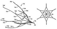
- FIG. 1is a perspective view of a first embodiment of the vein filter of the present invention in the collapsed configuration
- FIG. 2is an enlarged side view of a portion of the vein filter of FIG. 1 ;
- FIG. 3is a perspective view of the vein filter of FIG. 1 in an expanded configuration
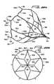
- FIG. 4Ais a side view of the vein filter of FIG. 1 in another expanded configuration
- FIG. 4Bis a front view of the vein filter of FIG. 4 in the expanded configuration
- FIG. 5is a side view of the vein filter of FIG. 3 in the expanded configuration
- FIG. 6Ais a close up view of a portion of the struts showing one embodiment of anchoring elements having pointed ends;
- FIG. 6Bis a close up view of a portion of one of the struts showing another embodiment of anchoring elements in the form of hemispherical cutouts;
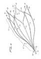
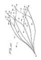
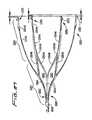
- FIG. 7is a perspective view of an alternate embodiment of the vein filter of the present invention shown in the expanded configuration
- FIG. 8is a side view of the vein filter of FIG. 7 ;
- FIG. 9is a side view of a portion of the vein filter of FIG. 7 shown in the collapsed configuration
- FIG. 10is a perspective view of another alternate embodiment of the vein filter of the present invention shown in the expanded configuration
- FIG. 11Ais a perspective view of yet another alternate embodiment of the vein filter of the present invention shown in the expanded configuration
- FIG. 11Bis a view similar to FIG. 11A showing an alternate embodiment of the hooks
- FIG. 11Cis a view similar to FIG. 11A showing another alternate embodiment of the hooks
- FIG. 11Dis a view similar to FIG. 11A showing yet another alternate embodiment of the filter of the present invention.
- FIG. 11Eis a perspective view of the filter of FIG. 11D in the collapsed position
- FIG. 11Fis an enlarged view of the retention hooks of FIG. 11D ;
- FIG. 11Gis a perspective view of an alternate embodiment of the filter of FIG. 7 having the retention hooks of FIG. 11D ;
- FIG. 11His an enlarged view of the retention hooks of FIG. 11G in the collapsed position
- FIG. 12Ais a close up perspective view of an alternate embodiment of an end of the filter having a series of cutouts to receive a retrieval snare;
- FIG. 12Bis a close up perspective view of an alternate embodiment of an end of the filter having cutouts to receive a retrieval snare;
- FIG. 12Cis a side view of the embodiment of FIG. 12B showing a retrieval snare placed in one of the cutouts between the coils;
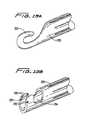
- FIG. 13Ais a close up perspective view of another alternate embodiment of an end of the filter having a hook to receive a retrieval snare;
- FIG. 13Bis a perspective view of an end of the filter illustrating another alternate embodiment of the hook to receive a retrieval snare;
- FIGS. 13C and 13Dare perspective and top views, respectively, of an alternate embodiment of the hook to receive a retrieval snare
- FIG. 13Eis a top view of an alternate embodiment of the hook of FIG. 13C ;
- FIGS. 13F and 13Gare perspective and side views, respectively, of another alternate embodiment of the hook to receive a retrieval snare
- FIGS. 13H-13Jare side views showing the method steps for engaging the hook of FIG. 13F for removing the filter utilizing a retrieval snare when the snare approaches from one orientation;
- FIGS. 13K-13Nare side views showing the method steps for engaging the hook of FIG. 13F for removing the filter utilizing a retrieval snare when the snare approaches from an orientation opposite the orientation of FIG. 13H ;
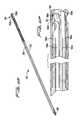
- FIGS. 14 , 15 and 16illustrate delivery and placement of the vessel filter of FIG. 1 in the inferior vena cava
- FIG. 14illustrates initial insertion of the delivery sheath through the femoral vein
- FIG. 15illustrates the delivery sheath being advanced toward the inferior vena cava just below (upstream) the juncture of the renal arteries
- FIG. 16illustrates the delivery sheath fully withdrawn to place the filter in the expanded placement configuration in the inferior vena cava
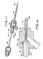
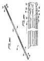
- FIG. 17is a perspective view of one embodiment of a delivery system for the vein filter
- FIG. 18is an exploded view of the delivery system of FIG. 17 ;
- FIG. 19is a cross-sectional view showing the engagement of the interlocking rails of the cartridge with the hub;
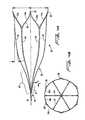
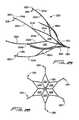
- FIG. 20Ais a perspective view of an alternate embodiment of the filter of the present invention having interconnecting struts in the filter portion, the filter shown in the expanded configuration;
- FIG. 20Bis a front view of the filter of FIG. 20A ;
- FIG. 20Cis a side view of the filter of FIG. 20A ;
- FIG. 20Dis a perspective view of the filter of FIG. 20A shown in the collapsed configuration
- FIG. 20Eis an enlarged view of an end portion of the filter of FIG. 20D showing the retention hooks;
- FIG. 20Fis an enlarged developed view of the end portion of the filter of FIG. 20D showing the axial relationship of the retention hooks;
- FIG. 21is a perspective view of another alternate embodiment of the filter having interconnecting struts in the filter portion;
- FIG. 22Ais a perspective view of another alternate embodiment of the filter of the present invention having interconnecting struts in the filter portion and in the mounting portion;
- FIGS. 22B and 22Care front and side views, respectively of the filter of FIG. 22A ;
- FIG. 22Dis a perspective view of the filter of FIG. 22A shown in the collapsed configuration
- FIG. 22Eis an enlarged view of an end region of the filter of FIG. 22D in the collapsed configuration
- FIG. 23is a perspective view of another alternate embodiment of the vein filter of the present invention in the collapsed configuration for delivery;
- FIG. 24is a close up perspective view of the retention hooks of the filter of FIG. 23 in the collapsed position
- FIG. 25is a perspective view of the vein filter of FIG. 23 in the expanded configuration
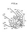
- FIG. 26is a front view of the filter of FIG. 25 ;
- FIG. 27is a side view of the filter of FIG. 25 showing the axial spacing of the retention hooks.
- FIG. 28is an enlarged developed view of the end portion of the filter of FIG. 27 .
- vein filter of the present inventionfor placement within the inferior vena cava to capture blood clots or other particles which could otherwise pass to the lungs.
- the filteris movable from a low profile collapsed configuration to facilitate insertion through the delivery sheath to a larger expanded placement configuration to enable atraumatic engagement with the vessel walls to secure (mount) the filter within the inferior vena cava.
- the filteris preferably substantially bell-shaped and preferably has a flared or mounting region (portion/section) and a filtering region (portion/section).
- the filtering portionhas inwardly directed struts, terminating in a converging region, thereby directing particles toward the central axis of the filter. By directing the particles to the center, they will be exposed to greater blood flow which improves dissolution of the particles.
- the other portionincreases in transverse dimension to form a flared region.
- the flareprovides less contact area than a straight region, resulting in less tissue ingrowth to facilitate removal of the filter if desired.
- the flarealso reduces the chance of vessel distortion if inserted into a curved vena cava.
- the filteris designated generally by reference numeral 10 and is shown in a collapsed configuration for delivery.
- Filter 10is preferably formed from a single tube 11 .
- the filter 10is composed of shape memory material, such as Nitinol, a nickel titanium alloy, or elgiloy, however, other materials such as stainless steel are also contemplated.
- a plurality of cutouts 12are formed in the filter 10 , preferably by laser cutting although other techniques are contemplated. In the illustrated embodiment, six elongated cutouts are formed, creating six strips or struts 14 of substantially uniform width separated by the cutouts 12 and extending from tubular portion 18 .
- the collapsed configuration of filter 10reduces the overall profile to facilitate delivery to the site.
- the diameter or transverse dimension of filter 10 in the collapsed configurationis represented by reference D 1 and preferably is about 2 mm and more preferably about 1.7 mm. Other dimensions are also contemplated.
- the diameter or transverse dimensions of the filter in the expanded placement configurationse.g. FIGS. 4A and 5 ) is greater than the diameter or transverse dimension D 1 in the collapsed (delivery) configuration.
- the filteris thus preferably dimensioned for insertion through a 6 French delivery system and through a 6 French catheter.
- FIGS. 3-5illustrate the expanded placement configuration of the filter 10 .
- Filter 10is generally bell-shaped in configuration.
- Filter 10has a flared region 17 and a converging region 21 at the filtering section 19 .
- the transverse dimension of the filter at flared (or mounting/anchoring) region 17is thus greater than the transverse dimension at filtering section 19 .
- the filtercan expand to a diameter D 2 shown in FIG. 5 .
- the filterexpands to a smaller diameter, e.g. D 3 , shown in FIG. 4 .
- Diameters (or transverse dimensions) D 2 -D 3preferably range from about 18 mm to about 32 mm, depending on the internal diameter of the vessel wall as will be explained in more detail below. Other dimensions are also contemplated.
- the elongated struts 14are spaced apart as shown and extend at an angle away from the longitudinal axis L of filter 10 in region 17 to provide a flare. Preferably, this angle or taper is about 10°, although other dimensions are contemplated.
- the struts 14curve or bend inwardly (region 23 ) toward the longitudinal axis and then extend inwardly at an angle to the tubular portion 18 , thereby forming an angle with the longitudinal axis.
- the six struts 14when expanded, are shown spaced approximately 60 degrees apart. It is also contemplated that a fewer or greater number of struts could be provided and spacing other than 60 degrees be provided.
- each elongated strut 14has an outer surface 20 for engagement with the vessel wall to retain the filter 10 in position in the vessel. This region is angled with respect to the longitudinal axis.
- the outer surface 20 of struts 14could be roughened to enhance engagement.
- a plurality of atraumatic tabs, barbs or other penetrating memberscan extend from the outer surface 20 of the struts 14 to engage the vessel wall to retain the filter.
- FIGS. 6A and 6Bshow examples of such retention features.
- the filterhas a series of hemispherical cutouts 152 formed along the length of the struts 154 forming pointed edges 156 to engage the vessel wall.
- the cutouts 152can be formed along the length of the strut 154 or alternatively be formed only along a portion of the length.
- the cutoutscan also be formed on fewer than all the struts.
- the filterhas anchoring elements 162 formed by cutouts 163 at the ends of the struts 164 .
- Anchoring elements 162have pointed ends 165 .
- the anchoring elements 162 and their pointed ends 165are aligned with the struts 164 , substantially parallel with the longitudinal axis of the filter to maintain a reduced profile.
- the pointed ends 165face outwardly as shown in FIG. 6A .
- Anchoring elements 162can be placed in the end regions of the strut or in other locations. The anchoring elements can also be placed in the opposite direction shown.
- the struts 174 of filter 170terminate in hooks 172 which extend substantially perpendicular from the strut. Hooks extend from the substantially V-shaped region 179 formed by the joining of connecting struts 174 a , 174 b .
- struts 184 of filter 180also terminate in substantially perpendicular hooks 182 , however this arrangement is achieved by torquing the connecting struts 184 a , 184 b at the curved region 185 so the hooks bend out of the plane.
- hooks 182extend from V-shaped region 189 formed by the connecting struts 184 a , 184 b .
- the hooks 192 of filter 190lie in the plane of the connecting struts 194 a , 194 b , flush with the width surface “w” of the V-shaped region 199 of connecting struts 194 a , 194 b.
- the hooks 302lie in the same plane as the connecting struts 304 a , 304 B of struts 310 as in FIG. 11B ; however the hooks of filter 301 are of two different sizes. More specifically, a first set of hooks 302 a is larger than a second set of hooks 302 b .
- hooks 302 aare formed so that they occupy a region equivalent to the transverse dimension of two adjacent struts.
- hook 302 aoccupies a region (dimension) of four connecting struts while smaller hook 302 b would only occupy the region (dimension) of two connecting struts.
- Smaller hooks 302 bare spaced axially inwardly with respect to larger hooks 302 a to minimize the collapsed profile (transverse dimension) of the filter when collapsed for insertion.
- smaller hooks 302 boccupy the space created by the larger hooks 302 a so they can be considered as nesting within larger hooks 306 a .
- each hook 302 bhas an outer surface 307 which conforms (follows the contour) to an inner surface 309 of a hook 306 a .
- the penetrating tips 306 a , 306 b in hooks 302 a , 302 brespectively, penetrate the tissue to retain the filter, preferably temporarily.
- hooks 172 , 182 , 192 , 302can be used with any of the disclosed embodiments (see e.g. FIG. 11G ). Such hooks can also be formed or placed on fewer than all the struts.
- the filtering section of filter 10 at a first end of the filteris designated generally by reference numeral 19 and includes the converging region 21 .
- Filtering section 19extends from the flared region 17 , and extends toward the central longitudinal axis L of the filter 10 and converges at portion 32 into tubular portion 18 .
- struts 14bend inwardly (region 23 ), then extend radially inwardly toward the tubular portion 18 , and transition to the tubular portion 18 .
- the tubular portion 18 and converging region 19 of the filter 10are spaced both axially outwardly and radially inwardly from the bend regions 23 of the strut 14 .
- aaxially outwardly
- radially inwardlyis represented by arrow “b” in FIG. 4A .
- the filteris designed to direct particles to the center of the filter and vessel. (Trapping the particles at the center rather than the edges of the filter is more desirable because there is less blood flow at the edges of the vessel and greater blood flow at the center to better dissolve the particles.)
- the non-labeled strutscan have the same configurations.
- each strut 14is divided into two connecting strut portions 14 a , 14 b .
- each strut portion 14 a , 14 bis about one half the width of the undivided strut 14 , although other widths are contemplated.
- the strut portions 14 a , 14 b of each divided strut 14extend in opposite directions and include a curved region 25 as the strut portions 14 a , 14 b each extend toward respective strut portion 14 a or 14 b of an adjacent strut.
- strut portions 14 a , 14 bform connecting portions to connect adjacent struts 14 as connecting strut 14 a of one strut is connected to connecting strut 14 b of an adjacent strut.
- Connecting strut portion 14 a on one strut and portion 14 b of another strutconverge at end region 29 of the filter and form a substantially V-shaped region.
- Six such V-shaped end portionsare preferably formed, each portion connecting adjacent struts. Note that although all six struts 14 are shown interconnected, it is also contemplated that fewer than all the struts can be interconnected.
- the filter 10can be viewed as having a filtering section 19 at a first end extending from the tubular portion 18 .
- each of the struts 14emerges from the tubular portion 18 at an angle that extends outwardly away from the center to transition to curved portions 23 .
- the curved portions 23extend outwardly away from the longitudinal axis forming a flare or region of progressively increasing transverse dimension.
- the struts 14are interconnected by connecting struts 14 a , 14 b that curve inwardly toward the connecting strut 14 a or 14 b of an adjacent strut to form a substantially V-shaped end portion.
- FIGS. 4A and 5illustrate by way of example two possible expanded dimensions of the filter; FIG. 4A showing expansion to a smaller dimension occurring in smaller diameter vessels and FIG. 5 showing expansion to a larger dimension occurring in larger diameter vessels.
- the filter tube of the embodiments described hereinis preferably made of shape memory metal material, such as Nitinol, a nickel titanium alloy.
- shape memory metal materialsuch as Nitinol, a nickel titanium alloy.
- the memorized configuration of the filter 10is shown in FIG. 1 .
- cold salinecan be injected into the delivery sheath or catheter 100 and around the filter 10 in its collapsed position within the delivery sheath 100 .
- This shape memory materialcharacteristically exhibits rigidity in the austenitic state and more flexibility in the martensitic state.
- the cold salinemaintains the temperature dependent filter 10 in a relatively softer condition as it is in the martensitic state within the sheath. This facilitates the exit of filter 10 from the sheath 100 as frictional contact between the filter 10 and the inner surface of the sheath would otherwise occur if the filter was maintained in a rigid, i.e. austenitic, condition.
- the filteris no longer cooled and is exposed to the warmer body temperature, which causes the filter 10 to return towards its austenitic memorized configuration.
- the filter 10(and other filters described herein) can be inserted through the jugular vein in the neck of the patient or through the femoral vein in the leg of the patient or the arm.
- the filterscan also be placed in the superior vena cava.
- FIGS. 14-16illustrate delivery and placement of the filter 10 , by way of example, in the inferior vena cava.
- Delivery catheter 100is inserted through the femoral vein “f” and advanced through the iliac arteries into the inferior vena cava. Delivery catheter would be withdrawn once the tip of the sheath is adjacent the structure so that withdrawal of the sheath would place the filter in the desired location of FIG. 16 .
- Tubing 104 and valve assembly 106enable saline injection.
- Delivery catheter 100is withdrawn to enable filter 10 to be warmed by body temperature to transition to the expanded placement configuration.
- the other filters described hereincould be inserted in the same manner. Note it is implanted in the orientation such that filter section 19 is downstream of the flared section 17 . This enables blood clots or other particles to be directed to the center of the filter section by the angled struts.
- the direction of insertione.g. upstream or downstream direction, will determine how the filter is to be positioned in the delivery catheter.
- the strut widthcan vary.
- the strutscan be wider at the flared region than at the filtering portion. This is preferably achieved by removing material to create the thinner portions. These thinner portions increase the flexibility of the filter for forming the angled and curved portions upon deployment.
- the filtercan have struts which are thinner, rather than wider, at the flared region, than at the angled and curved regions of the filtering portion. This would provide more stability at the curved regions.
- the adjustment of the widthsis designed to strike a balance between stability and flexibility of the various regions of the filter.
- other width variationsare contemplated such as making multiple width changes within each strut and/or in different struts.
- FIGS. 7-9illustrate an alternate embodiment of the filter, designated by reference numeral 110 .
- Filter 110is similar to filter 10 except for end region 121 . That is, like filter 10 , filter 110 has a filtering region 119 which extends from the flared (anchoring/mounting) region 117 , and extends toward the central longitudinal axis L of the filter 110 and converges at portion 132 into tubular portion 118 . Struts 114 bend inwardly toward the longitudinal axis of the filter 10 at region 123 . For clarity, not all of these sections of each strut 114 are labeled in the drawing, it being understood that the non-labeled struts can have the same configurations.
- the flared region 117 as in filter 10is of an angle preferably about 8 degrees although other angles are contemplated.
- the end region 121 of filter 110 where the struts 114 interconnectdiffers from filter 10 .
- the struts 114are interconnected by connecting strut portions 114 a , 114 b that curve outwardly away from the central axis and then inwardly toward each other to form a substantially V-shaped end portion 127 .
- the connecting strutsare joined to connecting struts of adjacent struts 114 (region 125 ).
- a closed geometric shape 133is formed as shown.
- the closed shape as shownis substantially oval in configuration, although other shapes are contemplated.
- each connecting adjacent strutssix such closed geometric shapes are preferably formed, each connecting adjacent struts, although fewer closed shapes are contemplated if fewer than all the struts are interconnected. Also, the length of the region 125 where the struts are joined can be shorter or longer than that shown, thereby changing the configuration of the closed geometric shape (e.g. making it longer or shorter).
- each strut 114divides into two connecting strut portions 114 a , 114 b which initially extend outwardly from each other. As each strut extends outwardly, the strut portion 114 a joins the strut portion 114 b of an adjacent strut at region 125 . After this joined region 125 , the strut portions 114 a and 114 b which emanate from the same strut extend inwardly towards each other and are joined at their ends into a substantially V-shaped end, designated by reference numeral 127 .
- FIG. 9The collapsed configuration of filter 110 is shown in FIG. 9 with cutouts 112 forming six struts 114 . Regions 113 illustrate where struts 114 divide.
- filter 150resembles filter 10 of FIG. 1 except for the additional connecting struts or ribs 152 .
- These ribsincrease the stability of the filter 150 .
- the two ribs 152extend from adjacent struts 154 and curve inwardly towards each other and are joined at region 156 (forming a V-like connection).
- the ribs 152can be arranged so they are axially aligned as in FIG. 10 or alternatively can be staggered i.e. spaced axially (not shown).
- the ribscan be placed between fewer than all the struts and the ribs can be utilized with any of the foregoing embodiments.
- Struts 154divide into connecting struts 154 a , 154 b in the embodiment of FIG. 1 .
- FIGS. 11G and 11Hillustrate an alternate embodiment of the filter of FIG. 7 having the hooks of filter 301 of FIG. 11D .
- Filter 350like filter 110 , has struts 354 which are interconnected by connecting strut portions 354 a , 354 b that curve outwardly then inwardly toward each other to form V-shaped portions 357 , terminating in hooks 356 .
- large hooks 356 aalternate with axially offset smaller hooks 356 b and are identical to hooks 306 a , 306 b of FIG. 11D .
- the ribscould curve radially outward near their tips, thus contacting the vessel wall and acting as a retaining mechanism.
- FIG. 20Aillustrates an alternate embodiment of the filter of the present invention.
- the strutsare interconnected at the filtering region rather than at the flared mounting (anchoring) region. This creates closed geometric shapes at the filtering region to enhance the clot capturing capability of the filter. Also, by providing the interconnection more forward (downstream) in the filter, i.e. in the filtering region (filtration zone), linear movement of the filter is facilitated to enhance removal of the filter.
- bell-shaped filter 700has a filtering region 719 and a flared anchoring (mounting) region 721 of greater transverse dimension.
- Flared region 721is preferably at an angle of about 8 degrees to about 14 degrees with respect to the longitudinal axis of the filter, although other angles are contemplated.
- the transverse dimensionincreases towards the anchoring end of the filter 700 so that as in the other embodiments disclosed herein, the terminal end of the filter at region 719 has a smaller transverse dimension than at the opposing terminal end at region 721 .
- the filtering region 719extends from the flared region 721 toward the longitudinal axis of the filter 700 and converges at portion 732 into tubular portion 718 at the filter end portion of filter 700 .
- Filtering region 719has six struts 714 curving outwardly from tubular portion 718 .
- Each filter strut or strut portion 714extends radially from tubular portion 718 and divides into two connecting filter struts or strut portions 714 a , 714 b (preferably of equal width) that angle way from each other (in different directions) to extend to the connecting strut portion of an adjacent strut 714 .
- connecting strut portion 714 a of one strut 714interconnects with the connecting strut portion 714 b of an adjacent strut at joining region 714 d .
- This forms closed geometric shapes 725preferably substantially diamond shaped in configuration.
- struts 714divide into connecting struts 714 a , 714 b of half the width, other dimensions are contemplated.
- strut portions 714 a , 714 bAfter convergence of strut portions 714 a , 714 b at joining region 714 d , it transitions into elongated mounting strut portions 714 c which form flared mounting or anchoring region 721 .
- the length of the strut portions 714 c in the anchoring region 721can vary, with increased/decreased length increasing the flexibility/rigidity of the struts.
- the thickness of the strut portionscan also vary to affect flexibility/rigidity.
- the strut portions 714 cterminate in hooks 740 a , 740 b similar to hooks 302 a , 302 b of FIG. 11D . That is, hooks 740 a and 740 b lie in the plane of the struts 714 c and hooks 740 a are larger than hooks 740 b , formed so they occupy a region equivalent to the transverse dimension of two adjacent struts. Smaller hooks 740 b nest within larger hooks 740 a as described above in conjunction with hooks 302 a , 302 b .
- hooks 740 bare spaced axially (inwardly) of hooks 740 a as well as spaced axially with respect to each other as represented by the arrows in FIG. 20F designating the three different distances E 1 , E 2 and E 3 in the developed view, presented for ease of understanding since the hooks are formed from a tube.
- Other hook designscould alternatively be provided, including the various hook embodiments described herein.
- the tubular portion 718is preferably in the form of a retrieval hook as described herein with respect to the other embodiments, and preferably in the form of retrieval hook 290 of FIG. 13F .
- Other retrieval structurecan also be utilized.
- the filteris designated generally by reference numeral 800 and has a filtering region 819 and a flared anchoring (mounting) region 821 .
- the filter 800differs from filter 700 in the additional joining regions of the connecting struts. More specifically, filter struts 814 extend radially from tubular portion 818 , in a similar manner as struts 714 of FIG. 20A . Struts 814 divide into connecting struts or strut portions 814 a , 814 b , extending in different directions, and then join at first joining regions 814 c to a connecting strut of an adjacent strut 814 .
- connecting struts or strut portions 814 f , 814 gextend in different directions, away from each other, to connect to another adjacent strut 814 f or 814 g at second joining regions 814 d .
- the mounting struts or strut portions 814 hextend longitudinally to form the flared mounting or anchoring region 821 .
- the interconnecting strutspreferably form a first set of substantially diamond shaped closed geometric shapes 830 as shown and a second set of substantially hexagonal shaped closed geometric shapes 832 . Other shapes are contemplated as are a different number of struts 814 , interconnecting struts, and closed geometric shapes. For clarity, not all identical parts are labeled in the drawings.
- hooks 840 a , 840 b as shownare identical to hooks 740 a , 740 b of FIG. 20 .
- Retrieval hook 850 at the tubular end portion 818 of the filtering end portion of filter 800is preferably identical to retrieval hook 750 of filter 700 .
- Other hook designs and retrieval structurecould alternatively be utilized.
- FIGS. 23-28illustrate an alternate embodiment of the filter of the present invention, designated generally by reference numeral 1010 .
- Filter 1010is substantially identical to filter 700 of FIGS. 20A-20E except for the retention hooks.
- Filter 1010has struts interconnected in the filtering region and not in the flared mounting (anchoring) region as in filter 700 . This creates closed geometric shapes at the filtering region to enhance the clot capturing capability of the filter.
- the mounting regionis devoid of such closed geometric shapes as it is devoid of interconnecting or connecting struts. This facilitates removal.
- Filter 1010is substantially bell shaped and has a filtering region 1012 and a flared anchoring (mounting) region 1024 of greater transverse dimension. Flared region 1024 is preferably at an angle of about 8 degrees with respect to the longitudinal axis of the filter, although other angles are contemplated. In this flared region 1024 , the transverse dimension increases towards the anchoring end of the filter 1010 so that as in the other embodiments disclosed herein, the terminal end of the filter at region 1019 has a smaller transverse dimension than at the opposing terminal end at region 1021 .
- the filtering region 1012extends from the flared region 1024 toward the longitudinal axis of the filter 1010 and converges at portion 1022 into tubular portion 1018 at the filter end portion of filter 1010 .
- Filtering region 1019preferably has six struts 1014 curving outwardly from tubular portion 1018 .
- Each filter strut or strut portion 1014extends radially from tubular portion 1018 and divides into two connecting (interconnecting) filter struts or strut portions 1014 a , 1014 b (preferably of equal width) that angle way from each other (in different directions) to extend to the connecting strut portion of an adjacent strut 1014 .
- connecting strut portion 1014 a of one strut 1014interconnects with the connecting strut portion 1014 b of an adjacent strut at joining region 1014 d .
- This forms closed geometric shapes 1025preferably substantially diamond shaped in configuration, although other shapes are contemplated.
- struts 1014divide into connecting struts 1014 a , 1014 b of half the width, other dimensions are contemplated.
- strut portions 1014 a , 1014 bAfter convergence of strut portions 1014 a , 1014 b at joining region 1014 d , it transitions into elongated mounting strut portions 1014 c which form flared mounting or anchoring region 1024 .
- the length of the strut portions 1014 c in the anchoring region 1024can vary, with increased/decreased length increasing the flexibility/rigidity of the struts.
- the thickness of the strut portionscan also vary to affect flexibility/rigidity.
- the strut portions 1014 cterminate in hook portions 1030 .
- Hook portions 1030 in this embodimentare preferably of substantially the same size.
- the hook portions or the struts from which they extendhave different lengths so that the distalmost end of the hook portions 1030 terminate at different axial positions. Stated another way, the hooks are staggered in an axial direction so the struts terminate at different points.
- FIG. 28illustrates the six different distances, in the developed view, presented for ease of understanding since the hooks are formed from a tube.
- Hook portions 1030lie in the plane of a distal portion 1014 d of the struts 1014 c . That is, the distal portion 1014 d of the strut 1014 c twists out of the plane of the remaining portion of the strut, with the hooks lying in the plane of the distal portion.
- Hook portions 1030includes a hook 1032 having a penetrating tip 1034 preferably pointing toward a proximal portion (filter region) of the filter 1010 .
- a top wall 1036 of the hook 1032has a slight step 1038 .
- the penetrating tip 1034extends about a curved wall 1039 .
- the penetrating tip 1034 in the illustrated embodimentextends substantially parallel to a longitudinal axis L 1 of the struts portion 1050 .
- Opposite the curved wall 1039 on hook 1032are a plurality of teeth 1040 , with points or edges facing in a distal direction, opposite the direction of the penetrating tip 1034 .
- Teeth 1040engage the vessel wall to provide additional retention to prevent movement of the implanted filter in the caudal direction.
- a heel 1044is formed on a distal end of the hook portion 1030 , terminating in a curved surface 1046 and extending distally beyond the hook 1032 . Heel 1044 extends past the hook 1032 to function as a stop to prevent the filter strut portions from going through the vessel wall.
- Hook portion 1030also has a reduced width dimension Z 1 which transition from the strut 1014 d to the hook 1032 . For clarity, only some of the hooks and hook portions are labeled in FIG. 28 .
- hook portions 1030somewhat nest within an adjacent hook portion. More specifically, the strut of portion 1030 has a reduced area 1049 (with width dimension Z 1 ) which forms a gap 1045 to receive a portion of heel 1044 of an adjacent hook portion 1030 . In this configuration, a portion of the heel 1044 of the hook portion 1030 is in general longitudinal alignment with a penetrating tip 1034 of an adjacent hook as described below.
- the strut 1014 d at the reduced area portion 1049has a first wall 1052 and a second wall 1054 forming a width Z 1 defined as the distance or space between the walls 1052 , 1054 .
- the strut 1014 d adjacent the reduced area 1049has a first wall 1056 and a second wall 1058 , forming a width Z 2 , defined as the distance or space between walls 1056 , 1058 .
- Line S 1represents this first wall 1056 of strut 1014 d .
- the hook 1032has a height Z 3 greater than height Z 2 such that it extends widthwise beyond the height of the first wall 1052 .
- width Z 1could be between about 0.013 inches to about 0.019 inches, and preferably about 0.016 inches
- width Z 2could be between about 0.025 inches to about 0.035 inches, and preferably about 0.030 inches
- width Z 3could be about 0.035 inches to about 0.045 inches, and preferably about 0.040 inches
- width Z 4 at the heel 1044could be between about 0.011 inches to about 0.017 inches, and preferably about 0.014 inches. It should be understood that other dimensions are also contemplated.
- Line S 3represents the second wall 1058 extrapolated in a proximal direction.
- the heel 1044extends widthwise beyond the line S 3 and width of the second wall 1054 .
- Wall 1058also includes a slight indentation 1055 to accommodate the penetrating tip portion 1034 of the adjacent hook 1032 .
- the tubular portion 1018is preferably in the form of a retrieval hook as described herein with respect to the other embodiments, and preferably in the form of retrieval hook 290 of FIG. 13F .
- Other retrieval structurecan also be utilized.
- FIG. 22illustrates an alternate embodiment of the filter of the present invention.
- the strutsare interconnected at the filtering region (filtration zone) and at the flared mounting (anchoring) region. These interconnecting struts at the filtering region enhance the clot capturing capability of the filter.
- the interconnection at the mounting regionenhances the stability of the filter and the vessel retention capability by reducing the flexibility of the struts.
- bell-shaped filter 900has a filtering region 919 and a flared anchoring (mounting) region 921 of greater transverse dimension.
- Flared region 921is preferably at an angle of about 8 degrees with respect to the longitudinal axis of the filter, although other angles are contemplated.
- the transverse dimensionincreases towards the anchoring end of the filter 900 so the terminal end of the filter at region 919 has a smaller transverse dimension than the opposing terminal end at region 921 .
- the filtering region 919extends from the flared region 921 toward the longitudinal axis of the filter 900 and converges at portion 932 into tubular portion 918 at the filter end portion of filter 900 .
- Filtering region 919has six struts 914 curving outwardly from tubular portion 918 .
- Each elongated filter strut or strut portion 914extends radially from tubular portion 918 and divides into two connecting filter struts or strut portions 914 a , 914 b (preferably of equal width) that angle way from each other (in different directions) to extend to the connecting strut portion of an adjacent strut 914 .
- connecting strut portion 914 a of one strut 914interconnects with the connecting strut portion 914 b of an adjacent strut at joining region 914 d .
- This forms closed geometric shapes 925preferably substantially diamond shaped in configuration.
- struts 914can divide into connecting struts 914 a , 914 b of half the width, other dimensions are contemplated such as equal to the width.
- each strut 914 cdivides into two connecting mounting strut portions 914 e , 914 f .
- Each strut portion 914 e , 914 fcan be one half the width of the undivided strut 14 , although other widths are contemplated such as equal to the width.
- the strut portions 914 e , 914 f of each divided strut 914 cextend in opposite directions and include a curved region as the strut portions 914 e , 914 f each extend toward respective strut portion 914 e or 914 f of an adjacent strut. That is, strut portions 914 e , 914 f form connecting portions to connect adjacent struts 914 c as connecting strut 914 e of one strut is connected to connecting strut 914 f of an adjacent strut.
- End region 929has an elongated region (or hook strut) 931 and preferably terminates in hooks described below. Note that although all six mounting struts 914 are shown interconnected, it is also contemplated that fewer than all the struts can be interconnected.
- the elongated strutshave a first angled region of interconnecting (connecting) struts 914 a , 914 b in the filtering region 919 and a second angled region of interconnecting (connecting) struts 914 e , 914 f in the mounting region 921 .
- the region of the interconnecting struts in the first regionhas a transverse dimension less than the transverse dimension of the region having the interconnecting struts in the mounting region.
- the filter strut portions and mounting strut portionseach divide into connecting struts of half the width.
- the filter struts and mounting strutsare also bifurcated, however the width of the connecting strut is increased so it is greater than one half the width of the struts and can for instance be equal to the width of the strut.
- Such bifurcation with increased widthis also applicable to the other embodiments of the filter described herein. Bifurcation with decreased width is also contemplated.
- the strut portions 914 cterminate in hooks 940 a , 940 b similar to hooks 302 a , 302 b of FIG. 11D . That is, hooks 940 a and 940 b lie in the plane of the struts 914 and hooks 940 a are larger than hooks 940 b , formed so they occupy a region equivalent to the transverse dimension of two adjacent struts. Smaller hooks 940 b nest within larger hooks 940 a in the same manner as described above in conjunction with hooks 302 a , 302 b .
- hooks 940 bare spaced axially (inwardly) of hooks 940 a as well as spaced axially with respect to each other in the same manner as described with respect to hooks 740 b of filter 700 and illustrated in FIG. 20F showing the three different distances E 1 , E 2 and E 3 in the developed view.
- Other hook designscould alternatively be provided, including the various hook embodiments described herein.
- the tubular portion 918is preferably in the form of a retrieval hook 950 as described herein with respect to the other embodiments, and preferably in the form of retrieval hook 290 of FIG. 13F .
- Other retrieval structurecan also be utilized.
- Filters 700 , 800 and 900are preferably manufactured from a cut tube, preferably laser cut. Therefore, as in the other embodiments described herein, terms such as interconnected, connected, joined, etc., are used for ease of description, it being understood that preferably these portions are integral as they are preferably formed from a single tube. Also, mounting struts and filter struts used to describe the various embodiments disclosed herein can be considered as mounting strut “portions” or “sections” and filter strut “portions” or “sections” of the same struts if the filter is formed integrally, e.g. from a cut tube.
- the foregoing filterscan be inserted through the femoral vein or alternatively through the internal jugular vein. It can be removed from access through the internal jugular vein or femoral vein.
- Various methodscan be used to remove the filter such as those described in commonly assigned application Ser. No. 09/911,097, filed Jul. 23, 2001, now published application 2002-0193827-A1, published Dec. 19, 2001, the entire contents of which is incorporated herein by reference, including for example, slotted hooks, graspers, etc.
- a recess or cutoutcan also be provided at the tubular end portions to receive a snare or other device for removal.
- a hook 222 at tubular portion 220is illustrated in the embodiment of FIG. 13A and is configured to receive a snare.
- FIG. 13Billustrates another embodiment of a hook.
- Hook 232 formed in tubular portion 230forms a cutout 234 for receiving a snare or other removal device.
- the snarecan surround and grasp both ears 235 .
- the gap 237 between the ears 235also enables a retrieval snare to lie in the gap 237 to surround and grasp one of the two ears 235 .
- hook 272is similar to hook 232 of FIG. 13B in that it has two ears 275 with a gap 277 therebetween. However it differs in that it has a bottom cutout 278 formed between walls 279 . It also differs in that surfaces 274 of ears 275 are rounded and outer proximal walls 278 a angle outwardly (proximally) to curved peak 276 then angle inwardly (wall 278 b ) to provide a smoother transition into the retrieval sheath. Thus, two angled transitions are provided.
- the side walls 284 extending into ears 285 of hook 282angle inwardly toward the longitudinal axis. Consequently, there are three angled transitions: 1) an angled transition in a first direction formed by angled walls 288 a which angle proximally outwardly from the edge 285 a of ears 285 to the curved peak 285 b (the proximal end of the hook is designated generally by reference numeral 283 ); 2) an angled transition in a second direction formed by angled walls 288 b which angle distally outwardly from curved peak 285 b ; and 3 ) an angled transition formed by walls 284 which angle proximally inwardly as walls 284 come closer together toward the proximal end.
- FIGS. 13F and 13Gillustrate another alternate embodiment of the retrieval hook of the present invention.
- Thisis the retrieval hook shown in conjunction with filter 301 of the embodiment of FIGS. 11D and 11G .
- Hook 290has a curved hook 292 at the proximalmost end.
- This hook 292is configured to receive a retrieval snare or other retrieval device.
- a portion of the wall of the hook 290is cut out to expose the annular interior surface 294 . That is, being formed from a laser cut tube, a wall portion is removed to expose curved inner wall surface 294 .
- This annular interior surface 294extends from radiused region 295 to proximalmost edge 296 .
- the interior surface 294can be considered to have an interior surface 294 a at the radiused region 295 and an interior surface 295 b at the hook 292 .
- the interior surface 294 baccommodates a portion of a tubular snare sheath. That is, the outer wall of the snare sheath (tube) can partially fit within the cut out region 293 . This enhances removal as the snare pulls the filter hook into collinear arrangement with the sheath tube. This can be appreciated by reference to FIGS. 13H-13J discussed below.
- the radiused region 295spaced axially (distal) from the hook 292 , includes a radiused or curved edge defined by radiused side walls 297 a , 297 c and top wall 297 b .
- the angled side walls 297 a , 297 cform camming surfaces to direct the hook 290 and filter into the retrieval sheath. This can be appreciated by reference to FIGS. 13K-13N discussed below.
- the hookcan be formed in other ways to provide an interior annular surface to function in a similar manner as surface 294 , i.e. to receive the snare tube.
- retrieval hookscan be used with any of the filters described herein.
- the snare 502is part of a retrieval system which includes a snare sheath or tube 504 through which the snare 502 extends.
- the distal wall 503 of snare sheath 504provides for cinching of the snare 502 .
- the snare sheath 504is inserted through retrieval sheath 510 . When the filter is pulled into the retrieval sheath 510 it is collapsed for removal.
- preferably cold salineis injected during the removal process to cool the sheath to transition to a softer martensitic state to facilitate removal.
- the snare sheath 504fits into the cut out region 293 as its outer wall conforms to the inner wall surface 294 b of hook 292 .
- the hook 290 and snare sheath 504become substantially collinear as shown in FIG. 13I .
- This collinear arrangementfacilitates retraction into the retrieval sheath 510 as it reduces the likelihood of a wall of the hook getting caught on the distal edge 512 of the retrieval sheath 510 , thus providing a smoother transition into the sheath as shown in FIG. 13J .
- FIGS. 13K-13Nillustrate the retrieval steps when the snare approaches from the opposite orientation of FIG. 13H , i.e. below the hook as viewed in the orientation of FIG. 13K .
- the wall 297 bcontacts the edge 512 of retrieval sheath 510 and due to the radiused walls 297 a , 297 c (depending on the side of contact), the hook is cammed downwardly (in the orientation of FIG. 13M ) into the retrieval sheath 510 as shown in FIG. 13N .
- Thisprovides a smooth transition into the retrieval sheath 510 as it reduces the likelihood of the hook being caught on the sheath edge.
- FIG. 12Aillustrates another embodiment having a series of recesses 210 along the length of the tubular portion 212 . This enables the tubular portion 212 to be grasped at several locations along its length, facilitating grasping of the filter for removal. These multiple recesses or cutouts 210 are axially spaced as shown.
- the end of the tubular portion 240has a series of axially spaced cutouts 242 which form a coil-like engagement structure.
- This engagement structureprovides multiple engagement areas for a retrieval (removal) device, such as a retrieval snare, for grasping the filter as the device can for instance be cinched in any of the spaces (formed by the cutouts) between the turns 246 in the helical coil.
- FIG. 12Cshows a snare 300 placed in one of the cutouts 242 .
- cold salinecan be injected onto the implanted filter to change the temperature of the filter to move it to a relatively softer condition to facilitate the filter being drawn in to the retrieval sheath. That is, injection of cold saline will cause the filter to approach its martensitic state, bringing the filter to a more flexible condition.
- the flexible conditionfacilitates the collapse and withdrawal of the filter into the retrieval sheath, by decreasing the frictional contact between the filter and the inner surface of the retrieval sheath.
- the delivery system 600includes a hub 602 , a cartridge 604 containing the filter, a pusher 606 and a wire 608 extending through the pusher 606 .
- the wire 608extends through the cartridge 604 and through the length of tube 603 to maintain a separation of the hooks, e.g. hooks 402 of filter 350 of FIG. 11G , during insertion of the delivery system and delivery of the filter.
- the cartridge 604is removably attached to the hub 602 , preferably by a snap-fit although other modes of attachment are also contemplated.
- the cartridgepreferably has markings (not shown) on the outer surface to indicate a femoral or jugular direction so the user knows the orientation to attach the cartridge 604 to hub 602 .
- advancement of the pusher 604advances the filter from the cartridge and through tube 603 as the distal edge of the pusher 604 abuts the proximal end of the filter, with the wire 608 (e.g., a Nitinol wire) preventing entanglement of the retention hooks.
- the wire 608also provides support (stability) for the pusher 604 as the pusher 604 is advanced over the wire 608 .
- the filteris forced out of the distal end of the tube, where it is no longer cooled by saline and is warmed by body temperature to return toward its memorized configuration.
- a locking mechanismcan be provided such as the mechanism of FIG. 19 .
- the cartridge 604has a pair of locking rails 612 a , 612 b , each including a respective recess 614 a , 614 b .
- the hub 602contains a detent 620 as shown.
- the recess 614 a of the locking rails 612 ais retained by the detent 620 . This locks the cartridge 604 to the hub 602 during use, preventing unwanted separation of the cartridge 604 from the hub 602 .
- the cartridgeis inserted so that recess 614 b of rail 612 b engages detent 620 of hub 602 .
- the filterscan be inserted in other regions of the body.
- any of the aforedescribed filterscan have mounting sections of varying thickness.
- the foregoing filterscan be made of materials other than shape memory material.
Landscapes
- Health & Medical Sciences (AREA)
- Engineering & Computer Science (AREA)
- Biomedical Technology (AREA)
- Life Sciences & Earth Sciences (AREA)
- Transplantation (AREA)
- Oral & Maxillofacial Surgery (AREA)
- Heart & Thoracic Surgery (AREA)
- Vascular Medicine (AREA)
- Cardiology (AREA)
- Animal Behavior & Ethology (AREA)
- General Health & Medical Sciences (AREA)
- Public Health (AREA)
- Veterinary Medicine (AREA)
- Surgical Instruments (AREA)
- Prostheses (AREA)
- External Artificial Organs (AREA)
Abstract
Description
Claims (6)
Priority Applications (3)
| Application Number | Priority Date | Filing Date | Title |
|---|---|---|---|
| US13/433,500US8591541B2 (en) | 2004-01-22 | 2012-03-29 | Vein filter |
| US14/076,181US9526604B2 (en) | 2004-01-22 | 2013-11-09 | Vessel filter |
| US15/358,985US10639139B2 (en) | 2004-01-22 | 2016-11-22 | Vein filter |
Applications Claiming Priority (9)
| Application Number | Priority Date | Filing Date | Title |
|---|---|---|---|
| US53837904P | 2004-01-22 | 2004-01-22 | |
| US10/805,796US7338512B2 (en) | 2004-01-22 | 2004-03-22 | Vein filter |
| US57227404P | 2004-05-18 | 2004-05-18 | |
| US10/889,429US7704266B2 (en) | 2004-01-22 | 2004-07-12 | Vein filter |
| US81820206P | 2006-06-30 | 2006-06-30 | |
| US11/801,547US7976562B2 (en) | 2004-01-22 | 2007-05-10 | Method of removing a vein filter |
| US11/978,821US8366736B2 (en) | 2004-01-22 | 2007-10-30 | Vein filter |
| US12/770,508US8162972B2 (en) | 2004-01-22 | 2010-04-29 | Vein filter |
| US13/433,500US8591541B2 (en) | 2004-01-22 | 2012-03-29 | Vein filter |
Related Parent Applications (1)
| Application Number | Title | Priority Date | Filing Date |
|---|---|---|---|
| US12/770,508ContinuationUS8162972B2 (en) | 2004-01-22 | 2010-04-29 | Vein filter |
Related Child Applications (1)
| Application Number | Title | Priority Date | Filing Date |
|---|---|---|---|
| US14/076,181ContinuationUS9526604B2 (en) | 2004-01-22 | 2013-11-09 | Vessel filter |
Publications (2)
| Publication Number | Publication Date |
|---|---|
| US20120184986A1 US20120184986A1 (en) | 2012-07-19 |
| US8591541B2true US8591541B2 (en) | 2013-11-26 |
Family
ID=44342999
Family Applications (4)
| Application Number | Title | Priority Date | Filing Date |
|---|---|---|---|
| US12/770,508Expired - LifetimeUS8162972B2 (en) | 2004-01-22 | 2010-04-29 | Vein filter |
| US13/433,500Expired - LifetimeUS8591541B2 (en) | 2004-01-22 | 2012-03-29 | Vein filter |
| US14/076,181Expired - Fee RelatedUS9526604B2 (en) | 2004-01-22 | 2013-11-09 | Vessel filter |
| US15/358,985Expired - LifetimeUS10639139B2 (en) | 2004-01-22 | 2016-11-22 | Vein filter |
Family Applications Before (1)
| Application Number | Title | Priority Date | Filing Date |
|---|---|---|---|
| US12/770,508Expired - LifetimeUS8162972B2 (en) | 2004-01-22 | 2010-04-29 | Vein filter |
Family Applications After (2)
| Application Number | Title | Priority Date | Filing Date |
|---|---|---|---|
| US14/076,181Expired - Fee RelatedUS9526604B2 (en) | 2004-01-22 | 2013-11-09 | Vessel filter |
| US15/358,985Expired - LifetimeUS10639139B2 (en) | 2004-01-22 | 2016-11-22 | Vein filter |
Country Status (4)
| Country | Link |
|---|---|
| US (4) | US8162972B2 (en) |
| EP (1) | EP2382945B1 (en) |
| CA (1) | CA2734482C (en) |
| ES (1) | ES2402899T3 (en) |
Cited By (1)
| Publication number | Priority date | Publication date | Assignee | Title |
|---|---|---|---|---|
| US20140066972A1 (en)* | 2004-01-22 | 2014-03-06 | Rex Medical, L.P. | Vessel filter |
Families Citing this family (26)
| Publication number | Priority date | Publication date | Assignee | Title |
|---|---|---|---|---|
| US7314477B1 (en) | 1998-09-25 | 2008-01-01 | C.R. Bard Inc. | Removable embolus blood clot filter and filter delivery unit |
| US9204956B2 (en) | 2002-02-20 | 2015-12-08 | C. R. Bard, Inc. | IVC filter with translating hooks |
| US7704267B2 (en) | 2004-08-04 | 2010-04-27 | C. R. Bard, Inc. | Non-entangling vena cava filter |
| US12115057B2 (en) | 2005-05-12 | 2024-10-15 | C.R. Bard, Inc. | Tubular filter |
| US8613754B2 (en) | 2005-05-12 | 2013-12-24 | C. R. Bard, Inc. | Tubular filter |
| CA2607580C (en) | 2005-05-12 | 2016-12-20 | C.R. Bard Inc. | Removable embolus blood clot filter |
| WO2007021340A1 (en) | 2005-08-09 | 2007-02-22 | C.R. Bard Inc | Embolus blood clot filter and delivery system |
| US9131999B2 (en) | 2005-11-18 | 2015-09-15 | C.R. Bard Inc. | Vena cava filter with filament |
| WO2007133366A2 (en) | 2006-05-02 | 2007-11-22 | C. R. Bard, Inc. | Vena cava filter formed from a sheet |
| US9326842B2 (en) | 2006-06-05 | 2016-05-03 | C. R . Bard, Inc. | Embolus blood clot filter utilizable with a single delivery system or a single retrieval system in one of a femoral or jugular access |
| WO2009032834A1 (en) | 2007-09-07 | 2009-03-12 | Crusader Medical Llc | Percutaneous permanent retrievable vascular filter |
| US8795318B2 (en)* | 2007-09-07 | 2014-08-05 | Merit Medical Systems, Inc. | Percutaneous retrievable vascular filter |
| US20120035647A1 (en)* | 2008-12-17 | 2012-02-09 | Rainer Bregulla | Body lumen filters with large surface area anchors |
| US8734480B2 (en) | 2011-08-05 | 2014-05-27 | Merit Medical Systems, Inc. | Vascular filter |
| US8740931B2 (en) | 2011-08-05 | 2014-06-03 | Merit Medical Systems, Inc. | Vascular filter |
| CN104023656B (en)* | 2011-12-05 | 2017-02-15 | Pi-R-方形有限公司 | Calcium deposits in broken heart valves |
| EP2816969B1 (en) | 2012-02-23 | 2018-06-13 | Merit Medical Systems, Inc. | Vascular filter |
| EP3030194B1 (en) | 2013-08-09 | 2019-03-13 | Merit Medical Systems, Inc. | Vascular filter delivery systems |
| US10010398B2 (en) | 2013-10-01 | 2018-07-03 | Cook Medical Technologies Llc | Filter device, system, and method |
| ES2614488T3 (en) | 2014-03-15 | 2017-05-31 | Argon Medical Devices, Inc. | Vein filter |
| US10159556B2 (en) | 2014-05-02 | 2018-12-25 | Argon Medical Devices, Inc. | Method of inserting a vein filter |
| GB2530313B (en)* | 2014-09-19 | 2016-09-14 | Cook Medical Technologies Llc | Spring lock implantable vascular device |
| US11331103B2 (en)* | 2018-03-29 | 2022-05-17 | Boston Scientific Scimed, Inc. | Occlusive medical device with fixation members |
| CN109248006B (en)* | 2018-09-25 | 2020-12-18 | 上海形状记忆合金材料有限公司 | a vena cava filter |
| US20210393277A1 (en)* | 2020-06-18 | 2021-12-23 | Neuravi Limited | Catheter mouth designs |
| DE102022114379A1 (en) | 2022-06-08 | 2023-12-14 | Acandis Gmbh | Medical device and manufacturing process |
Citations (195)
| Publication number | Priority date | Publication date | Assignee | Title |
|---|---|---|---|---|
| US3744492A (en) | 1971-04-07 | 1973-07-10 | S Leibinsohn | Drip chamber |
| US3952747A (en) | 1974-03-28 | 1976-04-27 | Kimmell Jr Garman O | Filter and filter insertion instrument |
| US4266815A (en) | 1978-07-03 | 1981-05-12 | Smiths Industries Limited | Connectors |
| US4425908A (en) | 1981-10-22 | 1984-01-17 | Beth Israel Hospital | Blood clot filter |
| US4494531A (en) | 1982-12-06 | 1985-01-22 | Cook, Incorporated | Expandable blood clot filter |
| US4512338A (en) | 1983-01-25 | 1985-04-23 | Balko Alexander B | Process for restoring patency to body vessels |
| DE3429850A1 (en) | 1984-05-12 | 1986-02-20 | Ing. Walter Hengst GmbH & Co KG, 4400 Münster | Improved blood filter for insertion into veins |
| US4619246A (en) | 1984-05-23 | 1986-10-28 | William Cook, Europe A/S | Collapsible filter basket |
| US4643184A (en) | 1982-09-29 | 1987-02-17 | Mobin Uddin Kazi | Embolus trap |
| US4688553A (en) | 1984-11-29 | 1987-08-25 | L. G. Medical S.A. | Filter, particularly for trapping blood clots |
| US4727873A (en) | 1984-04-17 | 1988-03-01 | Mobin Uddin Kazi | Embolus trap |
| FR2567405B1 (en) | 1984-07-12 | 1988-08-12 | Lefebvre Jean Marie | MEDICAL FILTER |
| US4781177A (en) | 1986-11-17 | 1988-11-01 | Promed | Blood clots filtering device |
| US4793348A (en) | 1986-11-15 | 1988-12-27 | Palmaz Julio C | Balloon expandable vena cava filter to prevent migration of lower extremity venous clots into the pulmonary circulation |
| US4817600A (en) | 1987-05-22 | 1989-04-04 | Medi-Tech, Inc. | Implantable filter |
| US4832055A (en) | 1988-07-08 | 1989-05-23 | Palestrant Aubrey M | Mechanically locking blood clot filter |
| US4957501A (en) | 1987-12-31 | 1990-09-18 | Biomat, S.A.R.L. | Anti-embolic filter |
| US4990156A (en) | 1988-06-21 | 1991-02-05 | Lefebvre Jean Marie | Filter for medical use |
| US4994069A (en) | 1988-11-02 | 1991-02-19 | Target Therapeutics | Vaso-occlusion coil and method |
| US5059205A (en) | 1989-09-07 | 1991-10-22 | Boston Scientific Corporation | Percutaneous anti-migration vena cava filter |
| US5133733A (en) | 1989-11-28 | 1992-07-28 | William Cook Europe A/S | Collapsible filter for introduction in a blood vessel of a patient |
| US5152777A (en) | 1989-01-25 | 1992-10-06 | Uresil Corporation | Device and method for providing protection from emboli and preventing occulsion of blood vessels |
| US5234458A (en) | 1990-06-15 | 1993-08-10 | Antheor | Filter device intended to prevent embolisms |
| US5300086A (en) | 1990-01-19 | 1994-04-05 | Pierre Gory | Device with a locating member for removably implanting a blood filter in a vein of the human body |
| US5324304A (en) | 1992-06-18 | 1994-06-28 | William Cook Europe A/S | Introduction catheter set for a collapsible self-expandable implant |
| US5344427A (en) | 1992-08-07 | 1994-09-06 | Celsa L.G. (Societe Anonyme) | Filter with triangular fingers |
| US5350398A (en) | 1991-05-13 | 1994-09-27 | Dusan Pavcnik | Self-expanding filter for percutaneous insertion |
| US5370657A (en) | 1993-03-26 | 1994-12-06 | Scimed Life Systems, Inc. | Recoverable thrombosis filter |
| US5375612A (en) | 1992-04-07 | 1994-12-27 | B. Braun Celsa | Possibly absorbable blood filter |
| US5382261A (en) | 1992-09-01 | 1995-01-17 | Expandable Grafts Partnership | Method and apparatus for occluding vessels |
| US5383887A (en) | 1992-12-28 | 1995-01-24 | Celsa Lg | Device for selectively forming a temporary blood filter |
| US5405377A (en) | 1992-02-21 | 1995-04-11 | Endotech Ltd. | Intraluminal stent |
| US5531788A (en) | 1989-10-09 | 1996-07-02 | Foundation Pour L'avenir Pour La Recherche Medicale Appliquee | Anti-Pulmonary embolism filter |
| US5591197A (en) | 1995-03-14 | 1997-01-07 | Advanced Cardiovascular Systems, Inc. | Expandable stent forming projecting barbs and method for deploying |
| US5601595A (en) | 1994-10-25 | 1997-02-11 | Scimed Life Systems, Inc. | Remobable thrombus filter |
| US5634942A (en) | 1994-04-21 | 1997-06-03 | B. Braun Celsa | Assembly comprising a blood filter for temporary or definitive use and a device for implanting it |
| US5681347A (en) | 1995-05-23 | 1997-10-28 | Boston Scientific Corporation | Vena cava filter delivery system |
| US5683411A (en) | 1994-04-06 | 1997-11-04 | William Cook Europe A/S | Medical article for implantation into the vascular system of a patient |
| US5690671A (en) | 1994-12-13 | 1997-11-25 | Micro Interventional Systems, Inc. | Embolic elements and methods and apparatus for their delivery |
| US5709704A (en) | 1994-11-30 | 1998-01-20 | Boston Scientific Corporation | Blood clot filtering |
| US5725552A (en) | 1994-07-08 | 1998-03-10 | Aga Medical Corporation | Percutaneous catheter directed intravascular occlusion devices |
| US5733329A (en) | 1996-12-30 | 1998-03-31 | Target Therapeutics, Inc. | Vaso-occlusive coil with conical end |
| US5733294A (en) | 1996-02-28 | 1998-03-31 | B. Braun Medical, Inc. | Self expanding cardiovascular occlusion device, method of using and method of making the same |
| US5755790A (en) | 1995-04-14 | 1998-05-26 | B. Braun Celsa | Intraluminal medical device |
| US5755779A (en) | 1995-12-07 | 1998-05-26 | Horiguchi; Sachio | Blood stream adjuster |
| US5776162A (en) | 1997-01-03 | 1998-07-07 | Nitinol Medical Technologies, Inc. | Vessel implantable shape memory appliance with superelastic hinged joint |
| US5782748A (en) | 1996-07-10 | 1998-07-21 | Symbiosis Corporation | Endoscopic surgical instruments having detachable proximal and distal portions |
| US5795322A (en) | 1995-04-10 | 1998-08-18 | Cordis Corporation | Catheter with filter and thrombus-discharge device |
| US5800457A (en) | 1997-03-05 | 1998-09-01 | Gelbfish; Gary A. | Intravascular filter and associated methodology |
| US5810874A (en) | 1996-02-22 | 1998-09-22 | Cordis Corporation | Temporary filter catheter |
| US5836968A (en) | 1996-07-17 | 1998-11-17 | Nitinol Medical Technologies, Inc. | Removable embolus blood clot filter |
| US5853420A (en) | 1994-04-21 | 1998-12-29 | B. Braun Celsa | Assembly comprising a blood filter for temporary or definitive use and device for implanting it, corresponding filter and method of implanting such a filter |
| US5893869A (en) | 1997-02-19 | 1999-04-13 | University Of Iowa Research Foundation | Retrievable inferior vena cava filter system and method for use thereof |
| US5895410A (en) | 1997-09-12 | 1999-04-20 | B. Braun Medical, Inc. | Introducer for an expandable vascular occlusion device |
| US5895398A (en) | 1996-02-02 | 1999-04-20 | The Regents Of The University Of California | Method of using a clot capture coil |
| US5911717A (en) | 1997-03-17 | 1999-06-15 | Precision Vascular Systems, Inc. | Catheter deliverable thrombogenic apparatus and method |
| US5938683A (en)* | 1994-01-10 | 1999-08-17 | Bentex Trading S.A. | Endovascular filter with flat fixing branches |
| US5968071A (en) | 1997-01-03 | 1999-10-19 | B. Braun Celsa | Blood filtering device having improved permeability |
| US5976172A (en) | 1996-07-03 | 1999-11-02 | Cordis Corporation | Retractable temporary vena cava filter |
| US5984947A (en) | 1998-05-04 | 1999-11-16 | Scimed Life Systems, Inc. | Removable thrombus filter |
| US6007558A (en) | 1998-09-25 | 1999-12-28 | Nitinol Medical Technologies, Inc. | Removable embolus blood clot filter |
| US6013093A (en) | 1995-11-28 | 2000-01-11 | Boston Scientific Corporation | Blood clot filtering |
| US6036702A (en) | 1997-04-23 | 2000-03-14 | Vascular Science Inc. | Medical grafting connectors and fasteners |
| US6042598A (en) | 1997-05-08 | 2000-03-28 | Embol-X Inc. | Method of protecting a patient from embolization during cardiac surgery |
| US6059825A (en) | 1992-03-05 | 2000-05-09 | Angiodynamics, Inc. | Clot filter |
| US6063113A (en) | 1995-06-13 | 2000-05-16 | William Cook Europe Aps | Device for implantation in a vessel or hollow organ lumen |
| US6066158A (en) | 1996-07-25 | 2000-05-23 | Target Therapeutics, Inc. | Mechanical clot encasing and removal wire |
| US6080178A (en) | 1999-04-20 | 2000-06-27 | Meglin; Allen J. | Vena cava filter |
| US6093196A (en) | 1998-02-05 | 2000-07-25 | Olympus Optical Co., Ltd. | Basket type grasping tool for surgery |
| US6093199A (en) | 1998-08-05 | 2000-07-25 | Endovascular Technologies, Inc. | Intra-luminal device for treatment of body cavities and lumens and method of use |
| US6096052A (en) | 1998-07-08 | 2000-08-01 | Ovion, Inc. | Occluding device and method of use |
| US6099549A (en) | 1998-07-03 | 2000-08-08 | Cordis Corporation | Vascular filter for controlled release |
| US6117154A (en) | 1995-11-07 | 2000-09-12 | Embol-X, Inc. | Cannula with associated filter and methods of use during cardiac surgery |
| US6123715A (en) | 1994-07-08 | 2000-09-26 | Amplatz; Curtis | Method of forming medical devices; intravascular occlusion devices |
| US6126673A (en) | 1993-10-01 | 2000-10-03 | Boston Scientific Corporation | Vena cava filter |
| US6146404A (en) | 1999-09-03 | 2000-11-14 | Scimed Life Systems, Inc. | Removable thrombus filter |
| US6152946A (en) | 1998-03-05 | 2000-11-28 | Scimed Life Systems, Inc. | Distal protection device and method |
| US6168579B1 (en) | 1999-08-04 | 2001-01-02 | Scimed Life Systems, Inc. | Filter flush system and methods of use |
| US6168603B1 (en) | 1995-02-02 | 2001-01-02 | Boston Scientific Corporation | Surgical extractor |
| US6171328B1 (en) | 1999-11-09 | 2001-01-09 | Embol-X, Inc. | Intravascular catheter filter with interlocking petal design and methods of use |
| US6171327B1 (en) | 1999-02-24 | 2001-01-09 | Scimed Life Systems, Inc. | Intravascular filter and method |
| US6179851B1 (en) | 1996-07-17 | 2001-01-30 | Scimed Life Systems, Inc. | Guiding catheter for positioning a medical device within an artery |
| US6179859B1 (en) | 1999-07-16 | 2001-01-30 | Baff Llc | Emboli filtration system and methods of use |
| US6187025B1 (en) | 1999-09-09 | 2001-02-13 | Noble-Met, Ltd. | Vascular filter |
| US6214025B1 (en) | 1994-11-30 | 2001-04-10 | Boston Scientific Corporation | Self-centering, self-expanding and retrievable vena cava filter |
| US6217600B1 (en) | 2000-01-26 | 2001-04-17 | Scimed Life Systems, Inc. | Thrombus filter with break-away anchor members |
| US6231581B1 (en) | 1998-12-16 | 2001-05-15 | Boston Scientific Corporation | Implantable device anchors |
| US6231589B1 (en) | 1999-03-22 | 2001-05-15 | Microvena Corporation | Body vessel filter |
| US6235044B1 (en) | 1999-08-04 | 2001-05-22 | Scimed Life Systems, Inc. | Percutaneous catheter and guidewire for filtering during ablation of mycardial or vascular tissue |
| US6241746B1 (en) | 1998-06-29 | 2001-06-05 | Cordis Corporation | Vascular filter convertible to a stent and method |
| US6245012B1 (en) | 1999-03-19 | 2001-06-12 | Nmt Medical, Inc. | Free standing filter |
| US6251122B1 (en) | 1999-09-02 | 2001-06-26 | Scimed Life Systems, Inc. | Intravascular filter retrieval device and method |
| US6267776B1 (en) | 1999-05-03 | 2001-07-31 | O'connell Paul T. | Vena cava filter and method for treating pulmonary embolism |
| US6273901B1 (en) | 1999-08-10 | 2001-08-14 | Scimed Life Systems, Inc. | Thrombosis filter having a surface treatment |
| US6280457B1 (en) | 1999-06-04 | 2001-08-28 | Scimed Life Systems, Inc. | Polymer covered vaso-occlusive devices and methods of producing such devices |
| US6280451B1 (en) | 1997-10-01 | 2001-08-28 | Scimed Life Systems, Inc. | Releasable basket |
| US6290721B1 (en) | 1992-03-31 | 2001-09-18 | Boston Scientific Corporation | Tubular medical endoprostheses |
| US6328755B1 (en) | 1998-09-24 | 2001-12-11 | Scimed Life Systems, Inc. | Filter delivery device |
| US6331184B1 (en) | 1999-12-10 | 2001-12-18 | Scimed Life Systems, Inc. | Detachable covering for an implantable medical device |
| US6331183B1 (en) | 1998-09-24 | 2001-12-18 | Scimed Life Systems, Inc. | Basket filter |
| US6342063B1 (en) | 2000-01-26 | 2002-01-29 | Scimed Life Systems, Inc. | Device and method for selectively removing a thrombus filter |
| US6342062B1 (en) | 1998-09-24 | 2002-01-29 | Scimed Life Systems, Inc. | Retrieval devices for vena cava filter |
| US6344041B1 (en) | 1996-07-26 | 2002-02-05 | David Kupiecki | Aneurysm closure device assembly |
| US6355051B1 (en) | 1999-03-04 | 2002-03-12 | Bioguide Consulting, Inc. | Guidewire filter device |
| US6368338B1 (en) | 1999-03-05 | 2002-04-09 | Board Of Regents, The University Of Texas | Occlusion method and apparatus |
| US6383205B1 (en) | 1997-09-30 | 2002-05-07 | Target Therapeutics, Inc. | Mechanical clot treatment device with distal filter |
| US20020058911A1 (en) | 1999-05-07 | 2002-05-16 | Paul Gilson | Support frame for an embolic protection device |
| US6402771B1 (en) | 1999-12-23 | 2002-06-11 | Guidant Endovascular Solutions | Snare |
| US6436120B1 (en) | 1999-04-20 | 2002-08-20 | Allen J. Meglin | Vena cava filter |
| US6436121B1 (en) | 2001-04-30 | 2002-08-20 | Paul H. Blom | Removable blood filter |
| US20020116024A1 (en) | 2001-02-20 | 2002-08-22 | Uresil Corporation | Blood clot filtering system |
| US6443972B1 (en) | 1997-11-19 | 2002-09-03 | Cordis Europa N.V. | Vascular filter |
| US6443971B1 (en) | 1999-12-21 | 2002-09-03 | Advanced Cardiovascular Systems, Inc. | System for, and method of, blocking the passage of emboli through a vessel |
| US6447530B1 (en) | 1996-11-27 | 2002-09-10 | Scimed Life Systems, Inc. | Atraumatic anchoring and disengagement mechanism for permanent implant device |
| US6458139B1 (en) | 1999-06-21 | 2002-10-01 | Endovascular Technologies, Inc. | Filter/emboli extractor for use in variable sized blood vessels |
| US6468290B1 (en) | 2000-06-05 | 2002-10-22 | Scimed Life Systems, Inc. | Two-planar vena cava filter with self-centering capabilities |
| US6482222B1 (en) | 2000-07-11 | 2002-11-19 | Rafael Medical Technologies Inc. | Intravascular filter |
| US20020193828A1 (en) | 2001-06-14 | 2002-12-19 | Cook Incorporated | Endovascular filter |
| US20020193827A1 (en) | 2001-06-18 | 2002-12-19 | Rex Medical | Removable vein filter |
| US6527962B1 (en) | 1999-11-26 | 2003-03-04 | B. Braun Medical | Blood filter having legs and centering elements integrally manufactured |
| US6537294B1 (en) | 2000-10-17 | 2003-03-25 | Advanced Cardiovascular Systems, Inc. | Delivery systems for embolic filter devices |
| US6540767B1 (en) | 2000-02-08 | 2003-04-01 | Scimed Life Systems, Inc. | Recoilable thrombosis filtering device and method |
| US6551342B1 (en) | 2001-08-24 | 2003-04-22 | Endovascular Technologies, Inc. | Embolic filter |
| US6562058B2 (en) | 2001-03-02 | 2003-05-13 | Jacques Seguin | Intravascular filter system |
| US6589265B1 (en) | 2000-10-31 | 2003-07-08 | Endovascular Technologies, Inc. | Intrasaccular embolic device |
| US20030130680A1 (en) | 2002-01-07 | 2003-07-10 | Scott Russell | Releasable and retrievable vascular filter system |
| US6599307B1 (en) | 2001-06-29 | 2003-07-29 | Advanced Cardiovascular Systems, Inc. | Filter device for embolic protection systems |
| US6605102B1 (en) | 1994-07-08 | 2003-08-12 | Ev3, Inc. | Intravascular trap and method of trapping particles in bodily fluids |
| US20030195555A1 (en) | 1999-11-08 | 2003-10-16 | Ev3 Sunnyvale, Inc., A California Corporation | Implant retrieval system |
| US20030208253A1 (en) | 2002-05-01 | 2003-11-06 | Ted Beyer | Blood clot filter |
| US20030208227A1 (en) | 2000-08-04 | 2003-11-06 | John Thomas | Temporary vascular filters and methods |
| US6652558B2 (en) | 2000-10-20 | 2003-11-25 | Angiodynamics, Inc. | Convertible blood clot filter |
| US6656202B2 (en) | 2000-07-14 | 2003-12-02 | Advanced Cardiovascular Systems, Inc. | Embolic protection systems |
| US6660021B1 (en) | 1999-12-23 | 2003-12-09 | Advanced Cardiovascular Systems, Inc. | Intravascular device and system |
| US6695878B2 (en) | 2000-06-26 | 2004-02-24 | Rex Medical, L.P. | Vascular device for valve leaflet apposition |
| US20040044361A1 (en) | 1998-11-06 | 2004-03-04 | Frazier Andrew G.C. | Detachable atrial appendage occlusion balloon |
| US20040073252A1 (en) | 2001-02-20 | 2004-04-15 | Mark Goldberg | Blood clot filtering system |
| US20040093017A1 (en) | 2002-11-06 | 2004-05-13 | Nmt Medical, Inc. | Medical devices utilizing modified shape memory alloy |
| WO2004049973A1 (en) | 2002-11-29 | 2004-06-17 | Vascular Interventional Technologies Inc. | Embolus blood clot filter |
| US20040158273A1 (en) | 2003-02-07 | 2004-08-12 | Scimed Life Systems, Inc. | Low profile IVC filter |
| US6793665B2 (en) | 2001-06-18 | 2004-09-21 | Rex Medical, L.P. | Multiple access vein filter |
| US20040186510A1 (en) | 2003-03-18 | 2004-09-23 | Scimed Life Systems, Inc. | Embolic protection ivc filter |
| US20040186556A1 (en) | 2002-12-24 | 2004-09-23 | Novostent Corporation | Vascular prosthesis and methods of use |
| US20040215230A1 (en) | 2003-04-28 | 2004-10-28 | Frazier Andrew G. C. | Left atrial appendage occlusion device with active expansion |
| US20040230220A1 (en) | 2003-02-11 | 2004-11-18 | Cook Incorporated | Removable vena cava filter |
| US20050004596A1 (en) | 2001-06-18 | 2005-01-06 | Mcguckin James F. | Vein filter |
| US20050015111A1 (en) | 2001-06-18 | 2005-01-20 | Mcguckin James F. | Vein filter |
| US20050027314A1 (en) | 2003-07-30 | 2005-02-03 | Scimed Life Systems, Inc. | Self-centering blood clot filter |
| US20050043757A1 (en) | 2000-06-12 | 2005-02-24 | Michael Arad | Medical devices formed from shape memory alloys displaying a stress-retained martensitic state and method for use thereof |
| WO2005034764A1 (en) | 2003-09-12 | 2005-04-21 | Nmt Medical, Inc. | Device and methods for preventing formation of thrombi in the left atrial appendage |
| US6890340B2 (en) | 2001-11-29 | 2005-05-10 | Medtronic Vascular, Inc. | Apparatus for temporary intraluminal protection |
| US20050165442A1 (en) | 2004-01-22 | 2005-07-28 | Thinnes John H.Jr. | Vein filter |
| US20050182439A1 (en) | 2004-02-13 | 2005-08-18 | Scimed Life Systems, Inc | Centering intravascular filters and devices and methods for deploying and retrieving intravascular filters |
| US6932831B2 (en) | 2001-07-13 | 2005-08-23 | B. Braun Medical Sas | Vascular protection system |
| US20050234503A1 (en) | 1998-09-25 | 2005-10-20 | Ravenscroft Adrian C | Removeable embolus blood clot filter and filter delivery unit |
| US20050251199A1 (en) | 2004-04-16 | 2005-11-10 | Osborne Thomas A | Removable vena cava filter with anchoring feature for reduced trauma |
| US20050267514A1 (en) | 2004-04-16 | 2005-12-01 | Osborne Thomas A | Removable vena cava filter |
| US6972025B2 (en) | 2003-11-18 | 2005-12-06 | Scimed Life Systems, Inc. | Intravascular filter with bioabsorbable centering element |
| US20050277977A1 (en) | 2004-06-10 | 2005-12-15 | Thornton Sally C | Invertible intravascular filter |
| US20050288704A1 (en) | 2004-06-25 | 2005-12-29 | Angiodynamics, Inc. | Retrievable blood clot filter |
| US6989021B2 (en)* | 2002-10-31 | 2006-01-24 | Cordis Corporation | Retrievable medical filter |
| US6994092B2 (en) | 1999-11-08 | 2006-02-07 | Ev3 Sunnyvale, Inc. | Device for containing embolic material in the LAA having a plurality of tissue retention structures |
| US20060030875A1 (en) | 2004-08-04 | 2006-02-09 | Tessmer Alexander W | Non-entangling vena cava filter |
| US7011094B2 (en) | 2001-03-02 | 2006-03-14 | Emphasys Medical, Inc. | Bronchial flow control devices and methods of use |
| US20060058832A1 (en) | 2002-12-12 | 2006-03-16 | Andreas Melzer | Vessel filter |
| US20060079928A1 (en) | 2004-09-29 | 2006-04-13 | Angiodynamics, Inc. | Permanent blood clot filter with capability of being retrieved |
| US20060079930A1 (en) | 2004-09-27 | 2006-04-13 | Mcguckin James F Jr | Vein filter |
| US7037321B2 (en) | 1996-02-23 | 2006-05-02 | Memory Medical Systems, Inc. | Medical device with slotted memory metal tube |
| US20060095068A1 (en) | 2004-11-03 | 2006-05-04 | Wasdyke Joel M | Retrievable vena cava filter |
| US20060100660A1 (en) | 2004-11-08 | 2006-05-11 | Cook Incorporated | Blood clot filter configured for a wire guide |
| US20060106417A1 (en) | 2004-11-12 | 2006-05-18 | Tessmer Alexander W | Filter delivery system |
| US20060149295A1 (en) | 2003-01-31 | 2006-07-06 | Fleming Iii James A | Filter retrieval catheter system, and methods |
| US20060178695A1 (en) | 2005-02-04 | 2006-08-10 | Decant Leonard J Jr | Vascular filter with sensing capability |
| US7097651B2 (en) | 2001-09-06 | 2006-08-29 | Advanced Cardiovascular Systems, Inc. | Embolic protection basket |
| US20060206138A1 (en) | 2005-03-09 | 2006-09-14 | Eidenschink Tracee E | Intravascular filter assembly |
| EP1707233A2 (en) | 1996-02-02 | 2006-10-04 | Transvascular, Inc. | Apparatus for blocking flow through blood vessels |
| US20070005095A1 (en) | 2004-04-16 | 2007-01-04 | Osborne Thomas A | Removable vena cava filter having inwardly positioned anchoring hooks in collapsed configuration |
| US20070032816A1 (en) | 2005-04-04 | 2007-02-08 | B.Braun Medical | Removable Filter Head |
| US7232462B2 (en) | 2004-03-31 | 2007-06-19 | Cook Incorporated | Self centering delivery catheter |
| US20070173885A1 (en) | 2006-01-20 | 2007-07-26 | Angiodynamics, Inc. | Retrievable blood clot filter |
| US7316708B2 (en) | 2002-12-05 | 2008-01-08 | Cardiac Dimensions, Inc. | Medical device delivery system |
| US7338512B2 (en) | 2004-01-22 | 2008-03-04 | Rex Medical, L.P. | Vein filter |
| US20080188887A1 (en) | 2007-02-07 | 2008-08-07 | Stanley Batiste | Removable vascular filter and method of filter placement |
| US20080221609A1 (en) | 2004-01-22 | 2008-09-11 | Mcguckin James F | Vein filter |
| US20080275486A1 (en) | 2007-05-01 | 2008-11-06 | Clifford Dwyer | Extended duration medical filter |
| US7534251B2 (en) | 2003-02-11 | 2009-05-19 | Boston Scientific Scimed, Inc. | Retrievable IVC filter |
| US20090198270A1 (en) | 2008-01-11 | 2009-08-06 | Mcguckin Jr James F | Vein Filter |
| US7572289B2 (en)* | 2004-01-27 | 2009-08-11 | Med Institute, Inc. | Anchoring barb for attachment to a medical prosthesis |
| US20100049239A1 (en) | 2004-01-22 | 2010-02-25 | Rex Medical, Lp | Vein Filter |
| US20100049238A1 (en) | 2006-12-19 | 2010-02-25 | C.R. Bard, Inc. | Inferior vena cava filter with stability features |
| US20100106178A1 (en) | 2008-10-29 | 2010-04-29 | Obermiller F Joseph | Vascular plugs |
| US7867245B2 (en) | 2004-02-09 | 2011-01-11 | The United States Of America As Represented By The Department Of Health And Human Services | Venous filters |
| US7875018B2 (en) | 2001-06-07 | 2011-01-25 | Cardiac Pacemakers, Inc. | Method for manipulating an adjustable shape guide catheter |
| EP1880693B1 (en) | 2006-07-18 | 2011-04-13 | Cordis Corporation | Twisted anchoring barb for stent of abdominal aortic aneurysm (AAA) device |
| US8029529B1 (en) | 2005-01-19 | 2011-10-04 | C. R. Bard, Inc. | Retrievable filter |
Family Cites Families (21)
| Publication number | Priority date | Publication date | Assignee | Title |
|---|---|---|---|---|
| US4781173A (en) | 1985-06-28 | 1988-11-01 | Juha Ven | Evaporating device and electric supply station provided with such an evaporating device |
| FR2660189B1 (en) | 1990-03-28 | 1992-07-31 | Lefebvre Jean Marie | DEVICE INTENDED TO BE IMPLANTED IN A VESSEL WITH SIDE LEGS WITH ANTAGONIST TEETH. |
| JP2573612Y2 (en) | 1991-12-30 | 1998-06-04 | ハナコメディカル株式会社 | Filter for thrombus filtration |
| US6232044B1 (en) | 1993-11-30 | 2001-05-15 | Raytheon Company | Infrared chopper using binary diffractive optics |
| US5704910A (en) | 1995-06-05 | 1998-01-06 | Nephros Therapeutics, Inc. | Implantable device and use therefor |
| US6096199A (en) | 1995-11-13 | 2000-08-01 | Dana Corporation | Oil filter cartridge with temperature sensitive bypass valve |
| WO1998023322A1 (en)* | 1996-11-27 | 1998-06-04 | Boston Scientific Corporation | Atraumatic anchoring and disengagement mechanism for permanent implant device |
| DE19853498A1 (en) | 1997-11-19 | 1999-07-01 | Bernd Kempkens | Floor covering pattern cutter |
| NL1007584C2 (en) | 1997-11-19 | 1999-05-20 | Cordis Europ | Vena cava filter. |
| AU2736901A (en) | 1999-12-23 | 2001-07-03 | Percusurge, Inc. | Strut design for an occlusion device |
| AU2001241603A1 (en)* | 2000-02-23 | 2001-09-03 | Boston Scientific Limited | Intravascular filtering devices and methods |
| US6953476B1 (en) | 2000-03-27 | 2005-10-11 | Neovasc Medical Ltd. | Device and method for treating ischemic heart disease |
| WO2002032496A1 (en) | 2000-10-18 | 2002-04-25 | Nmt Medical, Inc. | Over-the-wire interlock attachment/detachment mechanism |
| US20030065345A1 (en) | 2001-09-28 | 2003-04-03 | Kevin Weadock | Anastomosis devices and methods for treating anastomotic sites |
| US6932931B2 (en) | 2001-12-04 | 2005-08-23 | Callaway Golf Company | Process for forming and removing a golf ball core or intermediate ball assembly |
| US20030181942A1 (en) | 2002-01-25 | 2003-09-25 | Sutton Gregg S. | Atrial appendage blood filtration systems |
| US8162972B2 (en)* | 2004-01-22 | 2012-04-24 | Rex Medical, Lp | Vein filter |
| US7976562B2 (en)* | 2004-01-22 | 2011-07-12 | Rex Medical, L.P. | Method of removing a vein filter |
| US8353926B2 (en) | 2004-04-15 | 2013-01-15 | Cordis Corporation | Long-term retrievable medical filter |
| ITMO20040129A1 (en) | 2004-05-25 | 2004-08-25 | G A M A H S S R L | BLOOD VESSEL FILTER. |
| EP1894543B1 (en) | 2006-08-29 | 2012-03-21 | Rex Medical, L.P. | Vein filter |
- 2010
- 2010-04-29USUS12/770,508patent/US8162972B2/ennot_activeExpired - Lifetime
- 2011
- 2011-03-22CACA2734482Apatent/CA2734482C/enactiveActive
- 2011-04-18EPEP11162807Apatent/EP2382945B1/enactiveActive
- 2011-04-18ESES11162807Tpatent/ES2402899T3/enactiveActive
- 2012
- 2012-03-29USUS13/433,500patent/US8591541B2/ennot_activeExpired - Lifetime
- 2013
- 2013-11-09USUS14/076,181patent/US9526604B2/ennot_activeExpired - Fee Related
- 2016
- 2016-11-22USUS15/358,985patent/US10639139B2/ennot_activeExpired - Lifetime
Patent Citations (212)
| Publication number | Priority date | Publication date | Assignee | Title |
|---|---|---|---|---|
| US3744492A (en) | 1971-04-07 | 1973-07-10 | S Leibinsohn | Drip chamber |
| US3952747A (en) | 1974-03-28 | 1976-04-27 | Kimmell Jr Garman O | Filter and filter insertion instrument |
| US4266815A (en) | 1978-07-03 | 1981-05-12 | Smiths Industries Limited | Connectors |
| US4425908A (en) | 1981-10-22 | 1984-01-17 | Beth Israel Hospital | Blood clot filter |
| US4643184A (en) | 1982-09-29 | 1987-02-17 | Mobin Uddin Kazi | Embolus trap |
| US4494531A (en) | 1982-12-06 | 1985-01-22 | Cook, Incorporated | Expandable blood clot filter |
| US4512338A (en) | 1983-01-25 | 1985-04-23 | Balko Alexander B | Process for restoring patency to body vessels |
| US4727873A (en) | 1984-04-17 | 1988-03-01 | Mobin Uddin Kazi | Embolus trap |
| DE3429850A1 (en) | 1984-05-12 | 1986-02-20 | Ing. Walter Hengst GmbH & Co KG, 4400 Münster | Improved blood filter for insertion into veins |
| US4619246A (en) | 1984-05-23 | 1986-10-28 | William Cook, Europe A/S | Collapsible filter basket |
| FR2567405B1 (en) | 1984-07-12 | 1988-08-12 | Lefebvre Jean Marie | MEDICAL FILTER |
| US4688553A (en) | 1984-11-29 | 1987-08-25 | L. G. Medical S.A. | Filter, particularly for trapping blood clots |
| US4793348A (en) | 1986-11-15 | 1988-12-27 | Palmaz Julio C | Balloon expandable vena cava filter to prevent migration of lower extremity venous clots into the pulmonary circulation |
| US4781177A (en) | 1986-11-17 | 1988-11-01 | Promed | Blood clots filtering device |
| US4817600A (en) | 1987-05-22 | 1989-04-04 | Medi-Tech, Inc. | Implantable filter |
| US4957501A (en) | 1987-12-31 | 1990-09-18 | Biomat, S.A.R.L. | Anti-embolic filter |
| US4990156A (en) | 1988-06-21 | 1991-02-05 | Lefebvre Jean Marie | Filter for medical use |
| US4832055A (en) | 1988-07-08 | 1989-05-23 | Palestrant Aubrey M | Mechanically locking blood clot filter |
| US4994069A (en) | 1988-11-02 | 1991-02-19 | Target Therapeutics | Vaso-occlusion coil and method |
| US5152777A (en) | 1989-01-25 | 1992-10-06 | Uresil Corporation | Device and method for providing protection from emboli and preventing occulsion of blood vessels |
| US5059205A (en) | 1989-09-07 | 1991-10-22 | Boston Scientific Corporation | Percutaneous anti-migration vena cava filter |
| US5531788A (en) | 1989-10-09 | 1996-07-02 | Foundation Pour L'avenir Pour La Recherche Medicale Appliquee | Anti-Pulmonary embolism filter |
| US5133733A (en) | 1989-11-28 | 1992-07-28 | William Cook Europe A/S | Collapsible filter for introduction in a blood vessel of a patient |
| US5300086A (en) | 1990-01-19 | 1994-04-05 | Pierre Gory | Device with a locating member for removably implanting a blood filter in a vein of the human body |
| US5234458A (en) | 1990-06-15 | 1993-08-10 | Antheor | Filter device intended to prevent embolisms |
| US5350398A (en) | 1991-05-13 | 1994-09-27 | Dusan Pavcnik | Self-expanding filter for percutaneous insertion |
| US5626605A (en) | 1991-12-30 | 1997-05-06 | Scimed Life Systems, Inc. | Thrombosis filter |
| US5405377A (en) | 1992-02-21 | 1995-04-11 | Endotech Ltd. | Intraluminal stent |
| US6059825A (en) | 1992-03-05 | 2000-05-09 | Angiodynamics, Inc. | Clot filter |
| US6290721B1 (en) | 1992-03-31 | 2001-09-18 | Boston Scientific Corporation | Tubular medical endoprostheses |
| US5375612A (en) | 1992-04-07 | 1994-12-27 | B. Braun Celsa | Possibly absorbable blood filter |
| US5324304A (en) | 1992-06-18 | 1994-06-28 | William Cook Europe A/S | Introduction catheter set for a collapsible self-expandable implant |
| US5344427A (en) | 1992-08-07 | 1994-09-06 | Celsa L.G. (Societe Anonyme) | Filter with triangular fingers |
| US5382261A (en) | 1992-09-01 | 1995-01-17 | Expandable Grafts Partnership | Method and apparatus for occluding vessels |
| US5383887A (en) | 1992-12-28 | 1995-01-24 | Celsa Lg | Device for selectively forming a temporary blood filter |
| US5370657A (en) | 1993-03-26 | 1994-12-06 | Scimed Life Systems, Inc. | Recoverable thrombosis filter |
| US6126673A (en) | 1993-10-01 | 2000-10-03 | Boston Scientific Corporation | Vena cava filter |
| US5938683A (en)* | 1994-01-10 | 1999-08-17 | Bentex Trading S.A. | Endovascular filter with flat fixing branches |
| US5683411A (en) | 1994-04-06 | 1997-11-04 | William Cook Europe A/S | Medical article for implantation into the vascular system of a patient |
| US5853420A (en) | 1994-04-21 | 1998-12-29 | B. Braun Celsa | Assembly comprising a blood filter for temporary or definitive use and device for implanting it, corresponding filter and method of implanting such a filter |
| US6193739B1 (en) | 1994-04-21 | 2001-02-27 | B. Braun Celsa | Assembly comprising a blood filter for temporary or definitive use and a device for implanting it, corresponding filter and method of implanting such a filter |
| US5634942A (en) | 1994-04-21 | 1997-06-03 | B. Braun Celsa | Assembly comprising a blood filter for temporary or definitive use and a device for implanting it |
| US6123715A (en) | 1994-07-08 | 2000-09-26 | Amplatz; Curtis | Method of forming medical devices; intravascular occlusion devices |
| US5725552A (en) | 1994-07-08 | 1998-03-10 | Aga Medical Corporation | Percutaneous catheter directed intravascular occlusion devices |
| US6605102B1 (en) | 1994-07-08 | 2003-08-12 | Ev3, Inc. | Intravascular trap and method of trapping particles in bodily fluids |
| US6447531B1 (en) | 1994-07-08 | 2002-09-10 | Aga Medical Corporation | Method of forming medical devices; intravascular occlusion devices |
| US5746767A (en) | 1994-10-25 | 1998-05-05 | Scimed Life Systems, Inc. | Removable thrombus filter |
| US5601595A (en) | 1994-10-25 | 1997-02-11 | Scimed Life Systems, Inc. | Remobable thrombus filter |
| US5709704A (en) | 1994-11-30 | 1998-01-20 | Boston Scientific Corporation | Blood clot filtering |
| US6214025B1 (en) | 1994-11-30 | 2001-04-10 | Boston Scientific Corporation | Self-centering, self-expanding and retrievable vena cava filter |
| US6165198A (en) | 1994-12-13 | 2000-12-26 | Medtronic, Inc. | Embolic elements and methods and apparatus for their delivery |
| US5690671A (en) | 1994-12-13 | 1997-11-25 | Micro Interventional Systems, Inc. | Embolic elements and methods and apparatus for their delivery |
| US6168603B1 (en) | 1995-02-02 | 2001-01-02 | Boston Scientific Corporation | Surgical extractor |
| US5591197A (en) | 1995-03-14 | 1997-01-07 | Advanced Cardiovascular Systems, Inc. | Expandable stent forming projecting barbs and method for deploying |
| US5795322A (en) | 1995-04-10 | 1998-08-18 | Cordis Corporation | Catheter with filter and thrombus-discharge device |
| US5755790A (en) | 1995-04-14 | 1998-05-26 | B. Braun Celsa | Intraluminal medical device |
| US6165179A (en) | 1995-05-23 | 2000-12-26 | Boston Scientific Corporation | Vena cava delivery system |
| US5681347A (en) | 1995-05-23 | 1997-10-28 | Boston Scientific Corporation | Vena cava filter delivery system |
| US6063113A (en) | 1995-06-13 | 2000-05-16 | William Cook Europe Aps | Device for implantation in a vessel or hollow organ lumen |
| US6235045B1 (en) | 1995-11-07 | 2001-05-22 | Embol-X, Inc. | Cannula with associated filter and methods of use |
| US6117154A (en) | 1995-11-07 | 2000-09-12 | Embol-X, Inc. | Cannula with associated filter and methods of use during cardiac surgery |
| US6013093A (en) | 1995-11-28 | 2000-01-11 | Boston Scientific Corporation | Blood clot filtering |
| US5755779A (en) | 1995-12-07 | 1998-05-26 | Horiguchi; Sachio | Blood stream adjuster |
| US5895398A (en) | 1996-02-02 | 1999-04-20 | The Regents Of The University Of California | Method of using a clot capture coil |
| EP1707233A2 (en) | 1996-02-02 | 2006-10-04 | Transvascular, Inc. | Apparatus for blocking flow through blood vessels |
| US5810874A (en) | 1996-02-22 | 1998-09-22 | Cordis Corporation | Temporary filter catheter |
| US7037321B2 (en) | 1996-02-23 | 2006-05-02 | Memory Medical Systems, Inc. | Medical device with slotted memory metal tube |
| US5733294A (en) | 1996-02-28 | 1998-03-31 | B. Braun Medical, Inc. | Self expanding cardiovascular occlusion device, method of using and method of making the same |
| US5976172A (en) | 1996-07-03 | 1999-11-02 | Cordis Corporation | Retractable temporary vena cava filter |
| US5782748A (en) | 1996-07-10 | 1998-07-21 | Symbiosis Corporation | Endoscopic surgical instruments having detachable proximal and distal portions |
| US5836968A (en) | 1996-07-17 | 1998-11-17 | Nitinol Medical Technologies, Inc. | Removable embolus blood clot filter |
| US6179851B1 (en) | 1996-07-17 | 2001-01-30 | Scimed Life Systems, Inc. | Guiding catheter for positioning a medical device within an artery |
| US6066158A (en) | 1996-07-25 | 2000-05-23 | Target Therapeutics, Inc. | Mechanical clot encasing and removal wire |
| US6344041B1 (en) | 1996-07-26 | 2002-02-05 | David Kupiecki | Aneurysm closure device assembly |
| US6447530B1 (en) | 1996-11-27 | 2002-09-10 | Scimed Life Systems, Inc. | Atraumatic anchoring and disengagement mechanism for permanent implant device |
| US5733329A (en) | 1996-12-30 | 1998-03-31 | Target Therapeutics, Inc. | Vaso-occlusive coil with conical end |
| US5968071A (en) | 1997-01-03 | 1999-10-19 | B. Braun Celsa | Blood filtering device having improved permeability |
| US5776162A (en) | 1997-01-03 | 1998-07-07 | Nitinol Medical Technologies, Inc. | Vessel implantable shape memory appliance with superelastic hinged joint |
| US5893869A (en) | 1997-02-19 | 1999-04-13 | University Of Iowa Research Foundation | Retrievable inferior vena cava filter system and method for use thereof |
| US5800457A (en) | 1997-03-05 | 1998-09-01 | Gelbfish; Gary A. | Intravascular filter and associated methodology |
| US5911717A (en) | 1997-03-17 | 1999-06-15 | Precision Vascular Systems, Inc. | Catheter deliverable thrombogenic apparatus and method |
| US6036702A (en) | 1997-04-23 | 2000-03-14 | Vascular Science Inc. | Medical grafting connectors and fasteners |
| US6042598A (en) | 1997-05-08 | 2000-03-28 | Embol-X Inc. | Method of protecting a patient from embolization during cardiac surgery |
| US5895410A (en) | 1997-09-12 | 1999-04-20 | B. Braun Medical, Inc. | Introducer for an expandable vascular occlusion device |
| US6383205B1 (en) | 1997-09-30 | 2002-05-07 | Target Therapeutics, Inc. | Mechanical clot treatment device with distal filter |
| US6280451B1 (en) | 1997-10-01 | 2001-08-28 | Scimed Life Systems, Inc. | Releasable basket |
| US6443972B1 (en) | 1997-11-19 | 2002-09-03 | Cordis Europa N.V. | Vascular filter |
| US6093196A (en) | 1998-02-05 | 2000-07-25 | Olympus Optical Co., Ltd. | Basket type grasping tool for surgery |
| US6152946A (en) | 1998-03-05 | 2000-11-28 | Scimed Life Systems, Inc. | Distal protection device and method |
| US5984947A (en) | 1998-05-04 | 1999-11-16 | Scimed Life Systems, Inc. | Removable thrombus filter |
| US6241746B1 (en) | 1998-06-29 | 2001-06-05 | Cordis Corporation | Vascular filter convertible to a stent and method |
| US6099549A (en) | 1998-07-03 | 2000-08-08 | Cordis Corporation | Vascular filter for controlled release |
| US6096052A (en) | 1998-07-08 | 2000-08-01 | Ovion, Inc. | Occluding device and method of use |
| US6093199A (en) | 1998-08-05 | 2000-07-25 | Endovascular Technologies, Inc. | Intra-luminal device for treatment of body cavities and lumens and method of use |
| US6328755B1 (en) | 1998-09-24 | 2001-12-11 | Scimed Life Systems, Inc. | Filter delivery device |
| US6342062B1 (en) | 1998-09-24 | 2002-01-29 | Scimed Life Systems, Inc. | Retrieval devices for vena cava filter |
| US6331183B1 (en) | 1998-09-24 | 2001-12-18 | Scimed Life Systems, Inc. | Basket filter |
| US6258026B1 (en) | 1998-09-25 | 2001-07-10 | Nitinol Medical Technologies, Inc. | Removable embolus blood clot filter and filter delivery unit |
| US20050234503A1 (en) | 1998-09-25 | 2005-10-20 | Ravenscroft Adrian C | Removeable embolus blood clot filter and filter delivery unit |
| US6007558A (en) | 1998-09-25 | 1999-12-28 | Nitinol Medical Technologies, Inc. | Removable embolus blood clot filter |
| US20040044361A1 (en) | 1998-11-06 | 2004-03-04 | Frazier Andrew G.C. | Detachable atrial appendage occlusion balloon |
| US6231581B1 (en) | 1998-12-16 | 2001-05-15 | Boston Scientific Corporation | Implantable device anchors |
| US6171327B1 (en) | 1999-02-24 | 2001-01-09 | Scimed Life Systems, Inc. | Intravascular filter and method |
| US6355051B1 (en) | 1999-03-04 | 2002-03-12 | Bioguide Consulting, Inc. | Guidewire filter device |
| US6368338B1 (en) | 1999-03-05 | 2002-04-09 | Board Of Regents, The University Of Texas | Occlusion method and apparatus |
| US6245012B1 (en) | 1999-03-19 | 2001-06-12 | Nmt Medical, Inc. | Free standing filter |
| US6231589B1 (en) | 1999-03-22 | 2001-05-15 | Microvena Corporation | Body vessel filter |
| US6080178A (en) | 1999-04-20 | 2000-06-27 | Meglin; Allen J. | Vena cava filter |
| US6436120B1 (en) | 1999-04-20 | 2002-08-20 | Allen J. Meglin | Vena cava filter |
| US6517559B1 (en) | 1999-05-03 | 2003-02-11 | O'connell Paul T. | Blood filter and method for treating vascular disease |
| US6267776B1 (en) | 1999-05-03 | 2001-07-31 | O'connell Paul T. | Vena cava filter and method for treating pulmonary embolism |
| US20020058911A1 (en) | 1999-05-07 | 2002-05-16 | Paul Gilson | Support frame for an embolic protection device |
| US6280457B1 (en) | 1999-06-04 | 2001-08-28 | Scimed Life Systems, Inc. | Polymer covered vaso-occlusive devices and methods of producing such devices |
| US6458139B1 (en) | 1999-06-21 | 2002-10-01 | Endovascular Technologies, Inc. | Filter/emboli extractor for use in variable sized blood vessels |
| US6179859B1 (en) | 1999-07-16 | 2001-01-30 | Baff Llc | Emboli filtration system and methods of use |
| US6235044B1 (en) | 1999-08-04 | 2001-05-22 | Scimed Life Systems, Inc. | Percutaneous catheter and guidewire for filtering during ablation of mycardial or vascular tissue |
| US6168579B1 (en) | 1999-08-04 | 2001-01-02 | Scimed Life Systems, Inc. | Filter flush system and methods of use |
| US6273901B1 (en) | 1999-08-10 | 2001-08-14 | Scimed Life Systems, Inc. | Thrombosis filter having a surface treatment |
| US6251122B1 (en) | 1999-09-02 | 2001-06-26 | Scimed Life Systems, Inc. | Intravascular filter retrieval device and method |
| US6146404A (en) | 1999-09-03 | 2000-11-14 | Scimed Life Systems, Inc. | Removable thrombus filter |
| US6187025B1 (en) | 1999-09-09 | 2001-02-13 | Noble-Met, Ltd. | Vascular filter |
| US6994092B2 (en) | 1999-11-08 | 2006-02-07 | Ev3 Sunnyvale, Inc. | Device for containing embolic material in the LAA having a plurality of tissue retention structures |
| US20030195555A1 (en) | 1999-11-08 | 2003-10-16 | Ev3 Sunnyvale, Inc., A California Corporation | Implant retrieval system |
| US6171328B1 (en) | 1999-11-09 | 2001-01-09 | Embol-X, Inc. | Intravascular catheter filter with interlocking petal design and methods of use |
| US6527962B1 (en) | 1999-11-26 | 2003-03-04 | B. Braun Medical | Blood filter having legs and centering elements integrally manufactured |
| US6331184B1 (en) | 1999-12-10 | 2001-12-18 | Scimed Life Systems, Inc. | Detachable covering for an implantable medical device |
| US6443971B1 (en) | 1999-12-21 | 2002-09-03 | Advanced Cardiovascular Systems, Inc. | System for, and method of, blocking the passage of emboli through a vessel |
| US6660021B1 (en) | 1999-12-23 | 2003-12-09 | Advanced Cardiovascular Systems, Inc. | Intravascular device and system |
| US6402771B1 (en) | 1999-12-23 | 2002-06-11 | Guidant Endovascular Solutions | Snare |
| US6217600B1 (en) | 2000-01-26 | 2001-04-17 | Scimed Life Systems, Inc. | Thrombus filter with break-away anchor members |
| US6342063B1 (en) | 2000-01-26 | 2002-01-29 | Scimed Life Systems, Inc. | Device and method for selectively removing a thrombus filter |
| US6540767B1 (en) | 2000-02-08 | 2003-04-01 | Scimed Life Systems, Inc. | Recoilable thrombosis filtering device and method |
| US6468290B1 (en) | 2000-06-05 | 2002-10-22 | Scimed Life Systems, Inc. | Two-planar vena cava filter with self-centering capabilities |
| US20050043757A1 (en) | 2000-06-12 | 2005-02-24 | Michael Arad | Medical devices formed from shape memory alloys displaying a stress-retained martensitic state and method for use thereof |
| US6695878B2 (en) | 2000-06-26 | 2004-02-24 | Rex Medical, L.P. | Vascular device for valve leaflet apposition |
| US6482222B1 (en) | 2000-07-11 | 2002-11-19 | Rafael Medical Technologies Inc. | Intravascular filter |
| US6656202B2 (en) | 2000-07-14 | 2003-12-02 | Advanced Cardiovascular Systems, Inc. | Embolic protection systems |
| US20030208227A1 (en) | 2000-08-04 | 2003-11-06 | John Thomas | Temporary vascular filters and methods |
| US6537294B1 (en) | 2000-10-17 | 2003-03-25 | Advanced Cardiovascular Systems, Inc. | Delivery systems for embolic filter devices |
| US6652558B2 (en) | 2000-10-20 | 2003-11-25 | Angiodynamics, Inc. | Convertible blood clot filter |
| US6589265B1 (en) | 2000-10-31 | 2003-07-08 | Endovascular Technologies, Inc. | Intrasaccular embolic device |
| US20020116024A1 (en) | 2001-02-20 | 2002-08-22 | Uresil Corporation | Blood clot filtering system |
| US6506205B2 (en) | 2001-02-20 | 2003-01-14 | Mark Goldberg | Blood clot filtering system |
| US20040073252A1 (en) | 2001-02-20 | 2004-04-15 | Mark Goldberg | Blood clot filtering system |
| US7011094B2 (en) | 2001-03-02 | 2006-03-14 | Emphasys Medical, Inc. | Bronchial flow control devices and methods of use |
| US6562058B2 (en) | 2001-03-02 | 2003-05-13 | Jacques Seguin | Intravascular filter system |
| US6436121B1 (en) | 2001-04-30 | 2002-08-20 | Paul H. Blom | Removable blood filter |
| US7875018B2 (en) | 2001-06-07 | 2011-01-25 | Cardiac Pacemakers, Inc. | Method for manipulating an adjustable shape guide catheter |
| US20020193828A1 (en) | 2001-06-14 | 2002-12-19 | Cook Incorporated | Endovascular filter |
| US20050015111A1 (en) | 2001-06-18 | 2005-01-20 | Mcguckin James F. | Vein filter |
| US6783538B2 (en) | 2001-06-18 | 2004-08-31 | Rex Medical, L.P | Removable vein filter |
| US6793665B2 (en) | 2001-06-18 | 2004-09-21 | Rex Medical, L.P. | Multiple access vein filter |
| US20020193827A1 (en) | 2001-06-18 | 2002-12-19 | Rex Medical | Removable vein filter |
| US20050004596A1 (en) | 2001-06-18 | 2005-01-06 | Mcguckin James F. | Vein filter |
| US6599307B1 (en) | 2001-06-29 | 2003-07-29 | Advanced Cardiovascular Systems, Inc. | Filter device for embolic protection systems |
| US6932831B2 (en) | 2001-07-13 | 2005-08-23 | B. Braun Medical Sas | Vascular protection system |
| US6551342B1 (en) | 2001-08-24 | 2003-04-22 | Endovascular Technologies, Inc. | Embolic filter |
| US7097651B2 (en) | 2001-09-06 | 2006-08-29 | Advanced Cardiovascular Systems, Inc. | Embolic protection basket |
| US6890340B2 (en) | 2001-11-29 | 2005-05-10 | Medtronic Vascular, Inc. | Apparatus for temporary intraluminal protection |
| US20030130680A1 (en) | 2002-01-07 | 2003-07-10 | Scott Russell | Releasable and retrievable vascular filter system |
| US6958074B2 (en) | 2002-01-07 | 2005-10-25 | Cordis Corporation | Releasable and retrievable vascular filter system |
| US20030208253A1 (en) | 2002-05-01 | 2003-11-06 | Ted Beyer | Blood clot filter |
| US6989021B2 (en)* | 2002-10-31 | 2006-01-24 | Cordis Corporation | Retrievable medical filter |
| US20040093017A1 (en) | 2002-11-06 | 2004-05-13 | Nmt Medical, Inc. | Medical devices utilizing modified shape memory alloy |
| US20050267515A1 (en)* | 2002-11-29 | 2005-12-01 | Vascular Interventional Technologies Inc. | Embolus blood clot filter |
| WO2004049973A1 (en) | 2002-11-29 | 2004-06-17 | Vascular Interventional Technologies Inc. | Embolus blood clot filter |
| US7316708B2 (en) | 2002-12-05 | 2008-01-08 | Cardiac Dimensions, Inc. | Medical device delivery system |
| US20060058832A1 (en) | 2002-12-12 | 2006-03-16 | Andreas Melzer | Vessel filter |
| US20040186556A1 (en) | 2002-12-24 | 2004-09-23 | Novostent Corporation | Vascular prosthesis and methods of use |
| US20060149295A1 (en) | 2003-01-31 | 2006-07-06 | Fleming Iii James A | Filter retrieval catheter system, and methods |
| US20040158273A1 (en) | 2003-02-07 | 2004-08-12 | Scimed Life Systems, Inc. | Low profile IVC filter |
| US20040230220A1 (en) | 2003-02-11 | 2004-11-18 | Cook Incorporated | Removable vena cava filter |
| US7534251B2 (en) | 2003-02-11 | 2009-05-19 | Boston Scientific Scimed, Inc. | Retrievable IVC filter |
| US20040186510A1 (en) | 2003-03-18 | 2004-09-23 | Scimed Life Systems, Inc. | Embolic protection ivc filter |
| US20040215230A1 (en) | 2003-04-28 | 2004-10-28 | Frazier Andrew G. C. | Left atrial appendage occlusion device with active expansion |
| US20050027314A1 (en) | 2003-07-30 | 2005-02-03 | Scimed Life Systems, Inc. | Self-centering blood clot filter |
| WO2005034764A1 (en) | 2003-09-12 | 2005-04-21 | Nmt Medical, Inc. | Device and methods for preventing formation of thrombi in the left atrial appendage |
| US6972025B2 (en) | 2003-11-18 | 2005-12-06 | Scimed Life Systems, Inc. | Intravascular filter with bioabsorbable centering element |
| US20100049239A1 (en) | 2004-01-22 | 2010-02-25 | Rex Medical, Lp | Vein Filter |
| US7704266B2 (en)* | 2004-01-22 | 2010-04-27 | Rex Medical, L.P. | Vein filter |
| US20080221609A1 (en) | 2004-01-22 | 2008-09-11 | Mcguckin James F | Vein filter |
| US7338512B2 (en) | 2004-01-22 | 2008-03-04 | Rex Medical, L.P. | Vein filter |
| US20050165442A1 (en) | 2004-01-22 | 2005-07-28 | Thinnes John H.Jr. | Vein filter |
| US7572289B2 (en)* | 2004-01-27 | 2009-08-11 | Med Institute, Inc. | Anchoring barb for attachment to a medical prosthesis |
| US7867245B2 (en) | 2004-02-09 | 2011-01-11 | The United States Of America As Represented By The Department Of Health And Human Services | Venous filters |
| US7323003B2 (en) | 2004-02-13 | 2008-01-29 | Boston Scientific Scimed, Inc. | Centering intravascular filters and devices and methods for deploying and retrieving intravascular filters |
| US20050182439A1 (en) | 2004-02-13 | 2005-08-18 | Scimed Life Systems, Inc | Centering intravascular filters and devices and methods for deploying and retrieving intravascular filters |
| US7232462B2 (en) | 2004-03-31 | 2007-06-19 | Cook Incorporated | Self centering delivery catheter |
| US20050251199A1 (en) | 2004-04-16 | 2005-11-10 | Osborne Thomas A | Removable vena cava filter with anchoring feature for reduced trauma |
| US20050267514A1 (en) | 2004-04-16 | 2005-12-01 | Osborne Thomas A | Removable vena cava filter |
| US20070005095A1 (en) | 2004-04-16 | 2007-01-04 | Osborne Thomas A | Removable vena cava filter having inwardly positioned anchoring hooks in collapsed configuration |
| US20050277977A1 (en) | 2004-06-10 | 2005-12-15 | Thornton Sally C | Invertible intravascular filter |
| US20050288704A1 (en) | 2004-06-25 | 2005-12-29 | Angiodynamics, Inc. | Retrievable blood clot filter |
| US20060030875A1 (en) | 2004-08-04 | 2006-02-09 | Tessmer Alexander W | Non-entangling vena cava filter |
| US20060079930A1 (en) | 2004-09-27 | 2006-04-13 | Mcguckin James F Jr | Vein filter |
| US20070088381A1 (en) | 2004-09-27 | 2007-04-19 | Mcguckin James F Jr | Vein filter |
| US7279000B2 (en) | 2004-09-29 | 2007-10-09 | Angiodynamics Inc | Permanent blood clot filter with capability of being retrieved |
| US20060079928A1 (en) | 2004-09-29 | 2006-04-13 | Angiodynamics, Inc. | Permanent blood clot filter with capability of being retrieved |
| US20060095068A1 (en) | 2004-11-03 | 2006-05-04 | Wasdyke Joel M | Retrievable vena cava filter |
| US20060100660A1 (en) | 2004-11-08 | 2006-05-11 | Cook Incorporated | Blood clot filter configured for a wire guide |
| US20060106417A1 (en) | 2004-11-12 | 2006-05-18 | Tessmer Alexander W | Filter delivery system |
| US8029529B1 (en) | 2005-01-19 | 2011-10-04 | C. R. Bard, Inc. | Retrievable filter |
| US20060178695A1 (en) | 2005-02-04 | 2006-08-10 | Decant Leonard J Jr | Vascular filter with sensing capability |
| US20060206138A1 (en) | 2005-03-09 | 2006-09-14 | Eidenschink Tracee E | Intravascular filter assembly |
| US20070032816A1 (en) | 2005-04-04 | 2007-02-08 | B.Braun Medical | Removable Filter Head |
| US20070173885A1 (en) | 2006-01-20 | 2007-07-26 | Angiodynamics, Inc. | Retrievable blood clot filter |
| EP1880693B1 (en) | 2006-07-18 | 2011-04-13 | Cordis Corporation | Twisted anchoring barb for stent of abdominal aortic aneurysm (AAA) device |
| US20100049238A1 (en) | 2006-12-19 | 2010-02-25 | C.R. Bard, Inc. | Inferior vena cava filter with stability features |
| US20080188887A1 (en) | 2007-02-07 | 2008-08-07 | Stanley Batiste | Removable vascular filter and method of filter placement |
| US20080275486A1 (en) | 2007-05-01 | 2008-11-06 | Clifford Dwyer | Extended duration medical filter |
| US20090198270A1 (en) | 2008-01-11 | 2009-08-06 | Mcguckin Jr James F | Vein Filter |
| US20100106178A1 (en) | 2008-10-29 | 2010-04-29 | Obermiller F Joseph | Vascular plugs |
Non-Patent Citations (5)
| Title |
|---|
| B. Braun Medical. Inc. Vena Tech(TM) Vena Cava Filters, Feb. 2000. |
| B. Braun Medical. Inc. Vena Tech™ Vena Cava Filters, Feb. 2000. |
| Cordis Corporation, TrapEase(TM) Permanent Vena Cava Filter. "A Small, Easy and Versatile System for Optimal Pulmonary Emboli Prevention", 2000 (4 pages). |
| Cordis Corporation, TrapEase™ Permanent Vena Cava Filter. "A Small, Easy and Versatile System for Optimal Pulmonary Emboli Prevention", 2000 (4 pages). |
| Gianturco-Roehm, Bird's Nest® Vena Cava Filter. |
Cited By (3)
| Publication number | Priority date | Publication date | Assignee | Title |
|---|---|---|---|---|
| US20140066972A1 (en)* | 2004-01-22 | 2014-03-06 | Rex Medical, L.P. | Vessel filter |
| US9526604B2 (en)* | 2004-01-22 | 2016-12-27 | Argon Medical Devices, Inc. | Vessel filter |
| US10639139B2 (en) | 2004-01-22 | 2020-05-05 | Argon Medical Devices, Inc. | Vein filter |
Also Published As
| Publication number | Publication date |
|---|---|
| US20170071719A1 (en) | 2017-03-16 |
| CA2734482C (en) | 2018-02-13 |
| CA2734482A1 (en) | 2011-10-29 |
| US20120184986A1 (en) | 2012-07-19 |
| EP2382945A3 (en) | 2011-11-23 |
| US9526604B2 (en) | 2016-12-27 |
| US8162972B2 (en) | 2012-04-24 |
| US10639139B2 (en) | 2020-05-05 |
| EP2382945B1 (en) | 2013-01-16 |
| ES2402899T3 (en) | 2013-05-10 |
| US20100312269A1 (en) | 2010-12-09 |
| EP2382945A2 (en) | 2011-11-02 |
| US20140066972A1 (en) | 2014-03-06 |
Similar Documents
| Publication | Publication Date | Title |
|---|---|---|
| US10639139B2 (en) | Vein filter | |
| US9763766B2 (en) | Vein filter | |
| US8696700B2 (en) | Vein filter | |
| US7338512B2 (en) | Vein filter | |
| US8920458B2 (en) | Vein filter | |
| US8062326B2 (en) | Vein filter | |
| US20150012034A1 (en) | Vein filter |
Legal Events
| Date | Code | Title | Description |
|---|---|---|---|
| STCF | Information on status: patent grant | Free format text:PATENTED CASE | |
| AS | Assignment | Owner name:ARGON MEDICAL DEVICES, INC., TEXAS Free format text:ASSIGNMENT OF ASSIGNORS INTEREST;ASSIGNOR:REX MEDICAL, L.P.;REEL/FRAME:037472/0151 Effective date:20151223 | |
| AS | Assignment | Owner name:REX MEDICAL, L.P., PENNSYLVANIA Free format text:ASSIGNMENT OF ASSIGNORS INTEREST;ASSIGNORS:MCGUCKIN, JAMES F., JR;BRESSLER, JAMES E.;THINNES, JOHN H.;AND OTHERS;SIGNING DATES FROM 20100715 TO 20100802;REEL/FRAME:037575/0790 | |
| AS | Assignment | Owner name:HEALTHCARE FINANCIAL SOLUTIONS, LLC, AS ADMINISTRA Free format text:FIRST LIEN PATENT SECURITY AGREEMENT;ASSIGNOR:ARGON MEDICAL DEVICES, INC.;REEL/FRAME:037703/0001 Effective date:20151223 | |
| AS | Assignment | Owner name:HEALTHCARE FINANCIAL SOLUTIONS, LLC, AS ADMINISTRA Free format text:SECOND LIEN PATENT SECURITY AGREEMENT;ASSIGNOR:ARGON MEDICAL DEVICES, INC.;REEL/FRAME:037827/0460 Effective date:20151223 | |
| FPAY | Fee payment | Year of fee payment:4 | |
| AS | Assignment | Owner name:MANAN MEDICAL PRODUCTS, INC., ILLINOIS Free format text:RELEASE OF FIRST LIEN PATENT SECURITY AGREEMENTS RECORDED AT REEL/FRAME 037703/0001, 037702/0592, 037702/0580, AND 037702/0497;ASSIGNOR:HEALTHCARE FINANCIAL SOLUTIONS, LLC, AS ADMINISTRATIVE AGENT;REEL/FRAME:045130/0706 Effective date:20180123 Owner name:LUTHER MEDICAL PRODUCTS, INC., ILLINOIS Free format text:RELEASE OF FIRST LIEN PATENT SECURITY AGREEMENTS RECORDED AT REEL/FRAME 037703/0001, 037702/0592, 037702/0580, AND 037702/0497;ASSIGNOR:HEALTHCARE FINANCIAL SOLUTIONS, LLC, AS ADMINISTRATIVE AGENT;REEL/FRAME:045130/0706 Effective date:20180123 Owner name:ARGON MEDICAL DEVICES, INC., ILLINOIS Free format text:RELEASE OF FIRST LIEN PATENT SECURITY AGREEMENTS RECORDED AT REEL/FRAME 037703/0001, 037702/0592, 037702/0580, AND 037702/0497;ASSIGNOR:HEALTHCARE FINANCIAL SOLUTIONS, LLC, AS ADMINISTRATIVE AGENT;REEL/FRAME:045130/0706 Effective date:20180123 Owner name:MEDICAL DEVICE TECHNOLOGIES, INC., ILLINOIS Free format text:RELEASE OF FIRST LIEN PATENT SECURITY AGREEMENTS RECORDED AT REEL/FRAME 037703/0001, 037702/0592, 037702/0580, AND 037702/0497;ASSIGNOR:HEALTHCARE FINANCIAL SOLUTIONS, LLC, AS ADMINISTRATIVE AGENT;REEL/FRAME:045130/0706 Effective date:20180123 Owner name:PROMEX TECHNOLOGIES, LLC, ILLINOIS Free format text:RELEASE OF FIRST LIEN PATENT SECURITY AGREEMENTS RECORDED AT REEL/FRAME 037703/0001, 037702/0592, 037702/0580, AND 037702/0497;ASSIGNOR:HEALTHCARE FINANCIAL SOLUTIONS, LLC, AS ADMINISTRATIVE AGENT;REEL/FRAME:045130/0525 Effective date:20180123 Owner name:PROMEX TECHNOLOGIES, LLC, ILLINOIS Free format text:RELEASE OF FIRST LIEN PATENT SECURITY AGREEMENTS RECORDED AT REEL/FRAME 037703/0001, 037702/0592, 037702/0580, AND 037702/0497;ASSIGNOR:HEALTHCARE FINANCIAL SOLUTIONS, LLC, AS ADMINISTRATIVE AGENT;REEL/FRAME:045130/0706 Effective date:20180123 Owner name:ARGON MEDICAL DEVICES, INC., ILLINOIS Free format text:RELEASE OF FIRST LIEN PATENT SECURITY AGREEMENTS RECORDED AT REEL/FRAME 037703/0001, 037702/0592, 037702/0580, AND 037702/0497;ASSIGNOR:HEALTHCARE FINANCIAL SOLUTIONS, LLC, AS ADMINISTRATIVE AGENT;REEL/FRAME:045130/0525 Effective date:20180123 Owner name:MEDICAL DEVICE TECHNOLOGIES, INC., ILLINOIS Free format text:RELEASE OF FIRST LIEN PATENT SECURITY AGREEMENTS RECORDED AT REEL/FRAME 037703/0001, 037702/0592, 037702/0580, AND 037702/0497;ASSIGNOR:HEALTHCARE FINANCIAL SOLUTIONS, LLC, AS ADMINISTRATIVE AGENT;REEL/FRAME:045130/0525 Effective date:20180123 Owner name:MANAN MEDICAL PRODUCTS, INC., ILLINOIS Free format text:RELEASE OF FIRST LIEN PATENT SECURITY AGREEMENTS RECORDED AT REEL/FRAME 037703/0001, 037702/0592, 037702/0580, AND 037702/0497;ASSIGNOR:HEALTHCARE FINANCIAL SOLUTIONS, LLC, AS ADMINISTRATIVE AGENT;REEL/FRAME:045130/0525 Effective date:20180123 Owner name:MEDICAL DEVICE TECHNOLOGIES, INC., ILLINOIS Free format text:RELEASE OF SECOND LIEN PATENT SECURITY AGREEMENTS RECORDED AT REEL/FRAME 037827/0460, 037827/0526, 037827/0764, AND 037827/0882;ASSIGNOR:HEALTHCARE FINANCIAL SOLUTIONS, LLC, AS ADMINISTRATIVE AGENT;REEL/FRAME:045130/0906 Effective date:20180123 Owner name:ARGON MEDICAL DEVICES, INC., ILLINOIS Free format text:RELEASE OF SECOND LIEN PATENT SECURITY AGREEMENTS RECORDED AT REEL/FRAME 037827/0460, 037827/0526, 037827/0764, AND 037827/0882;ASSIGNOR:HEALTHCARE FINANCIAL SOLUTIONS, LLC, AS ADMINISTRATIVE AGENT;REEL/FRAME:045130/0906 Effective date:20180123 Owner name:LUTHER MEDICAL PRODUCTS, INC., ILLINOIS Free format text:RELEASE OF SECOND LIEN PATENT SECURITY AGREEMENTS RECORDED AT REEL/FRAME 037827/0460, 037827/0526, 037827/0764, AND 037827/0882;ASSIGNOR:HEALTHCARE FINANCIAL SOLUTIONS, LLC, AS ADMINISTRATIVE AGENT;REEL/FRAME:045130/0906 Effective date:20180123 Owner name:PROMEX TECHNOLOGIES, LLC, ILLINOIS Free format text:RELEASE OF SECOND LIEN PATENT SECURITY AGREEMENTS RECORDED AT REEL/FRAME 037827/0460, 037827/0526, 037827/0764, AND 037827/0882;ASSIGNOR:HEALTHCARE FINANCIAL SOLUTIONS, LLC, AS ADMINISTRATIVE AGENT;REEL/FRAME:045130/0906 Effective date:20180123 Owner name:MANAN MEDICAL PRODUCTS, INC., ILLINOIS Free format text:RELEASE OF SECOND LIEN PATENT SECURITY AGREEMENTS RECORDED AT REEL/FRAME 037827/0460, 037827/0526, 037827/0764, AND 037827/0882;ASSIGNOR:HEALTHCARE FINANCIAL SOLUTIONS, LLC, AS ADMINISTRATIVE AGENT;REEL/FRAME:045130/0906 Effective date:20180123 | |
| AS | Assignment | Owner name:UBS AG, STAMFORD BRANCH, AS COLLATERAL AGENT, CONNECTICUT Free format text:SECOND LIEN PATENT SECURITY AGREEMENT;ASSIGNORS:ARGON MEDICAL DEVICES, INC.;MEDICAL DEVICE TECHNOLOGIES, INC.;MANAN MEDICAL PRODUCTS, INC.;REEL/FRAME:046127/0602 Effective date:20180123 Owner name:UBS AG, STAMFORD BRANCH, AS COLLATERAL AGENT, CONNECTICUT Free format text:FIRST LIEN PATENT SECURITY AGREEMENT;ASSIGNORS:ARGON MEDICAL DEVICES, INC.;MEDICAL DEVICE TECHNOLOGIES, INC.;MANAN MEDICAL PRODUCTS, INC.;REEL/FRAME:046127/0748 Effective date:20180123 Owner name:UBS AG, STAMFORD BRANCH, AS COLLATERAL AGENT, CONN Free format text:FIRST LIEN PATENT SECURITY AGREEMENT;ASSIGNORS:ARGON MEDICAL DEVICES, INC.;MEDICAL DEVICE TECHNOLOGIES, INC.;MANAN MEDICAL PRODUCTS, INC.;REEL/FRAME:046127/0748 Effective date:20180123 Owner name:UBS AG, STAMFORD BRANCH, AS COLLATERAL AGENT, CONN Free format text:SECOND LIEN PATENT SECURITY AGREEMENT;ASSIGNORS:ARGON MEDICAL DEVICES, INC.;MEDICAL DEVICE TECHNOLOGIES, INC.;MANAN MEDICAL PRODUCTS, INC.;REEL/FRAME:046127/0602 Effective date:20180123 | |
| AS | Assignment | Owner name:ARGON MEDICAL DEVICES, INC., ILLINOIS Free format text:TERMINATION AND RELEASE OF FIRST LIEN SECURITY INTEREST IN PATENTS;ASSIGNOR:UBS AG, STAMFORD BRANCH, AS COLLATERAL AGENT;REEL/FRAME:050375/0599 Effective date:20190912 Owner name:MANAN MEDICAL PRODUCTS, INC., ILLINOIS Free format text:TERMINATION AND RELEASE OF SECOND LIEN SECURITY INTEREST IN PATENTS;ASSIGNOR:UBS AG, STAMFORD BRANCH, AS COLLATERAL AGENT;REEL/FRAME:050375/0620 Effective date:20190912 Owner name:ARGON MEDICAL DEVICES, INC., ILLINOIS Free format text:TERMINATION AND RELEASE OF SECOND LIEN SECURITY INTEREST IN PATENTS;ASSIGNOR:UBS AG, STAMFORD BRANCH, AS COLLATERAL AGENT;REEL/FRAME:050375/0620 Effective date:20190912 Owner name:MANAN MEDICAL PRODUCTS, INC., ILLINOIS Free format text:TERMINATION AND RELEASE OF FIRST LIEN SECURITY INTEREST IN PATENTS;ASSIGNOR:UBS AG, STAMFORD BRANCH, AS COLLATERAL AGENT;REEL/FRAME:050375/0599 Effective date:20190912 Owner name:MEDICAL DEVICE TECHNOLOGIES, INC., ILLINOIS Free format text:TERMINATION AND RELEASE OF SECOND LIEN SECURITY INTEREST IN PATENTS;ASSIGNOR:UBS AG, STAMFORD BRANCH, AS COLLATERAL AGENT;REEL/FRAME:050375/0620 Effective date:20190912 Owner name:MEDICAL DEVICE TECHNOLOGIES, INC., ILLINOIS Free format text:TERMINATION AND RELEASE OF FIRST LIEN SECURITY INTEREST IN PATENTS;ASSIGNOR:UBS AG, STAMFORD BRANCH, AS COLLATERAL AGENT;REEL/FRAME:050375/0599 Effective date:20190912 | |
| MAFP | Maintenance fee payment | Free format text:PAYMENT OF MAINTENANCE FEE, 8TH YEAR, LARGE ENTITY (ORIGINAL EVENT CODE: M1552); ENTITY STATUS OF PATENT OWNER: LARGE ENTITY Year of fee payment:8 | |
| AS | Assignment | Owner name:ARGON MEDICAL DEVICES, INC., TEXAS Free format text:CHANGE OF OWNER/ASSIGNEE ADDRESS;ASSIGNOR:ARGON MEDICAL DEVICES, INC.;REEL/FRAME:062437/0600 Effective date:20230119 | |
| AS | Assignment | Owner name:HSBC BANK USA, NATIONAL ASSOCIATION, AS COLLATERAL AGENT, NEW YORK Free format text:SECURITY INTEREST;ASSIGNORS:ARGON MEDICAL DEVICES, INC.;MEDICAL DEVICE TECHNOLOGIES, INC.;MANAN MEDICAL PRODUCTS, INC.;REEL/FRAME:065612/0206 Effective date:20190912 | |
| AS | Assignment | Owner name:HSBC BANK USA, NATIONAL ASSOCIATION, AS COLLATERAL AGENT, NEW YORK Free format text:SECURITY INTEREST;ASSIGNORS:ARGON MEDICAL DEVICES, INC.;MEDICAL DEVICE TECHNOLOGIES, INC.;MANAN MEDICAL PRODUCTS, INC.;REEL/FRAME:066816/0020 Effective date:20240318 | |
| AS | Assignment | Owner name:MANAN MEDICAL PRODUCTS, INC., TEXAS Free format text:RELEASE BY SECURED PARTY;ASSIGNOR:HSBC BANK USA, NATIONAL ASSOCIATION, AS COLLATERAL AGENT;REEL/FRAME:066883/0812 Effective date:20240318 Owner name:MEDICAL DEVICE TECHNOLOGIES, INC., TEXAS Free format text:RELEASE BY SECURED PARTY;ASSIGNOR:HSBC BANK USA, NATIONAL ASSOCIATION, AS COLLATERAL AGENT;REEL/FRAME:066883/0812 Effective date:20240318 Owner name:ARGON MEDICAL DEVICES, INC., TEXAS Free format text:RELEASE BY SECURED PARTY;ASSIGNOR:HSBC BANK USA, NATIONAL ASSOCIATION, AS COLLATERAL AGENT;REEL/FRAME:066883/0812 Effective date:20240318 | |
| FEPP | Fee payment procedure | Free format text:MAINTENANCE FEE REMINDER MAILED (ORIGINAL EVENT CODE: REM.); ENTITY STATUS OF PATENT OWNER: LARGE ENTITY |