US8591465B2 - Device for administering an injectable product - Google Patents
Device for administering an injectable productDownload PDFInfo
- Publication number
- US8591465B2 US8591465B2US11/417,518US41751806AUS8591465B2US 8591465 B2US8591465 B2US 8591465B2US 41751806 AUS41751806 AUS 41751806AUS 8591465 B2US8591465 B2US 8591465B2
- Authority
- US
- United States
- Prior art keywords
- plunger rod
- plunger
- drive direction
- spring
- product
- Prior art date
- Legal status (The legal status is an assumption and is not a legal conclusion. Google has not performed a legal analysis and makes no representation as to the accuracy of the status listed.)
- Active, expires
Links
Images


Classifications
- A—HUMAN NECESSITIES
- A61—MEDICAL OR VETERINARY SCIENCE; HYGIENE
- A61M—DEVICES FOR INTRODUCING MEDIA INTO, OR ONTO, THE BODY; DEVICES FOR TRANSDUCING BODY MEDIA OR FOR TAKING MEDIA FROM THE BODY; DEVICES FOR PRODUCING OR ENDING SLEEP OR STUPOR
- A61M5/00—Devices for bringing media into the body in a subcutaneous, intra-vascular or intramuscular way; Accessories therefor, e.g. filling or cleaning devices, arm-rests
- A61M5/178—Syringes
- A61M5/20—Automatic syringes, e.g. with automatically actuated piston rod, with automatic needle injection, filling automatically
- A61M5/2033—Spring-loaded one-shot injectors with or without automatic needle insertion
- A—HUMAN NECESSITIES
- A61—MEDICAL OR VETERINARY SCIENCE; HYGIENE
- A61M—DEVICES FOR INTRODUCING MEDIA INTO, OR ONTO, THE BODY; DEVICES FOR TRANSDUCING BODY MEDIA OR FOR TAKING MEDIA FROM THE BODY; DEVICES FOR PRODUCING OR ENDING SLEEP OR STUPOR
- A61M5/00—Devices for bringing media into the body in a subcutaneous, intra-vascular or intramuscular way; Accessories therefor, e.g. filling or cleaning devices, arm-rests
- A61M5/178—Syringes
- A61M5/20—Automatic syringes, e.g. with automatically actuated piston rod, with automatic needle injection, filling automatically
- A61M2005/2006—Having specific accessories
- A61M2005/2013—Having specific accessories triggering of discharging means by contact of injector with patient body
- A—HUMAN NECESSITIES
- A61—MEDICAL OR VETERINARY SCIENCE; HYGIENE
- A61M—DEVICES FOR INTRODUCING MEDIA INTO, OR ONTO, THE BODY; DEVICES FOR TRANSDUCING BODY MEDIA OR FOR TAKING MEDIA FROM THE BODY; DEVICES FOR PRODUCING OR ENDING SLEEP OR STUPOR
- A61M5/00—Devices for bringing media into the body in a subcutaneous, intra-vascular or intramuscular way; Accessories therefor, e.g. filling or cleaning devices, arm-rests
- A61M5/178—Syringes
- A61M5/20—Automatic syringes, e.g. with automatically actuated piston rod, with automatic needle injection, filling automatically
- A61M2005/206—With automatic needle insertion
- A—HUMAN NECESSITIES
- A61—MEDICAL OR VETERINARY SCIENCE; HYGIENE
- A61M—DEVICES FOR INTRODUCING MEDIA INTO, OR ONTO, THE BODY; DEVICES FOR TRANSDUCING BODY MEDIA OR FOR TAKING MEDIA FROM THE BODY; DEVICES FOR PRODUCING OR ENDING SLEEP OR STUPOR
- A61M5/00—Devices for bringing media into the body in a subcutaneous, intra-vascular or intramuscular way; Accessories therefor, e.g. filling or cleaning devices, arm-rests
- A61M5/178—Syringes
- A61M5/20—Automatic syringes, e.g. with automatically actuated piston rod, with automatic needle injection, filling automatically
- A61M2005/2073—Automatic syringes, e.g. with automatically actuated piston rod, with automatic needle injection, filling automatically preventing premature release, e.g. by making use of a safety lock
- A—HUMAN NECESSITIES
- A61—MEDICAL OR VETERINARY SCIENCE; HYGIENE
- A61M—DEVICES FOR INTRODUCING MEDIA INTO, OR ONTO, THE BODY; DEVICES FOR TRANSDUCING BODY MEDIA OR FOR TAKING MEDIA FROM THE BODY; DEVICES FOR PRODUCING OR ENDING SLEEP OR STUPOR
- A61M5/00—Devices for bringing media into the body in a subcutaneous, intra-vascular or intramuscular way; Accessories therefor, e.g. filling or cleaning devices, arm-rests
- A61M5/178—Syringes
- A61M5/24—Ampoule syringes, i.e. syringes with needle for use in combination with replaceable ampoules or carpules, e.g. automatic
- A—HUMAN NECESSITIES
- A61—MEDICAL OR VETERINARY SCIENCE; HYGIENE
- A61M—DEVICES FOR INTRODUCING MEDIA INTO, OR ONTO, THE BODY; DEVICES FOR TRANSDUCING BODY MEDIA OR FOR TAKING MEDIA FROM THE BODY; DEVICES FOR PRODUCING OR ENDING SLEEP OR STUPOR
- A61M5/00—Devices for bringing media into the body in a subcutaneous, intra-vascular or intramuscular way; Accessories therefor, e.g. filling or cleaning devices, arm-rests
- A61M5/178—Syringes
- A61M5/31—Details
- A61M5/32—Needles; Details of needles pertaining to their connection with syringe or hub; Accessories for bringing the needle into, or holding the needle on, the body; Devices for protection of needles
- A61M5/3202—Devices for protection of the needle before use, e.g. caps
- A—HUMAN NECESSITIES
- A61—MEDICAL OR VETERINARY SCIENCE; HYGIENE
- A61M—DEVICES FOR INTRODUCING MEDIA INTO, OR ONTO, THE BODY; DEVICES FOR TRANSDUCING BODY MEDIA OR FOR TAKING MEDIA FROM THE BODY; DEVICES FOR PRODUCING OR ENDING SLEEP OR STUPOR
- A61M5/00—Devices for bringing media into the body in a subcutaneous, intra-vascular or intramuscular way; Accessories therefor, e.g. filling or cleaning devices, arm-rests
- A61M5/178—Syringes
- A61M5/31—Details
- A61M5/32—Needles; Details of needles pertaining to their connection with syringe or hub; Accessories for bringing the needle into, or holding the needle on, the body; Devices for protection of needles
- A61M5/3205—Apparatus for removing or disposing of used needles or syringes, e.g. containers; Means for protection against accidental injuries from used needles
- A61M5/321—Means for protection against accidental injuries by used needles
- A61M5/3243—Means for protection against accidental injuries by used needles being axially-extensible, e.g. protective sleeves coaxially slidable on the syringe barrel
- A61M5/326—Fully automatic sleeve extension, i.e. in which triggering of the sleeve does not require a deliberate action by the user
Definitions
- the inventionrelates to devices for administering, injecting, delivering or dispensing substances, and to methods of making and using such devices. More particularly, it relates to a device for administering an injectable product wherein the device may be an automatic injector.
- Injection devices of the type to which the invention relatesare known from DE 198 22 031 B and U.S. Pat. No. 4,031,893. Both documents describe automatic injectors.
- a mechanical sequence controllerensures that once the device has been triggered, the injection cannula is inserted through the skin to the desired depth in a first phase and the product to be injected is not dispensed and administered until a subsequent second phase.
- the injection device disclosed in U.S. Pat. No. 4,031,893does not have such a sequence controller.
- a drive mechanismapplies pressure to push a plunger disposed in a container filled with the product, and both the container and hence also the injection cannula and the plunger in the container are pushed in a forward direction due to static friction.
- the insertion and dispensing proceduresdo not, therefore, take place exactly sequentially and instead also take place simultaneously to a certain extent.
- the plunger of the respective devicesis driven forwards by means of a plunger rod and a spring acting on the plunger rod in the forward-drive (or injection or delivery) direction of the plunger.
- the springis accommodated in a drive cup and pushes the cup against a proximal end of the plunger rod.
- the springdirectly surrounds the plunger rod and pushes in the forward direction against a shoulder of the plunger rod which projects radially outwards.
- the plunger rodis either fixedly connected to the plunger directly or is connected to an intermediate piece fixedly connected to the plunger, which serves as an adapter for adapting to different filling levels of the container.
- the present inventionprovides a way of shortening devices for administering an injectable product.
- the present inventioncomprises a device for administering an injectable product comprising a housing, a displaceable product container accommodated by the housing, a plunger in the container so that the plunger can be displaced in a forward-drive direction to administer the product, a plunger rod acting on the plunger in the forward-drive direction and having a releasable retained position, and a spring acting on the plunger rod in the forward-drive direction, the plunger rod releaseably held in the retained position in a retaining engagement against the force of the spring, wherein the spring projects into the container in the retained position.
- the present inventioncomprises a device for administering an injectable product comprising a housing, a container for the product mounted or carried by the housing and incorporating a plunger, a plunger rod and a spring acting on the plunger rod.
- a forward-drive directionwhich also might be thought of as the injection or delivery direction
- the productis dispensed from the container.
- the springacts on the plunger rod in the forward-drive direction.
- the plunger rod and the springare constituent components of a drive unit for the plunger or constitute such a drive unit on their own.
- the devicemay also have an injection cannula, which points in the forward-drive direction.
- the deviceWhen the device is in an initial state, for example immediately before administering a product, the device is “armed”, i.e. the spring is tensed, and the plunger rod is held in a retained position in a retaining engagement against the force of the tensed spring.
- the retaining engagementmay be effected directly between the housing and the plunger rod or, in some preferred embodiments, between these two components but initially via one or more transmitting elements.
- the retaining engagementis releasable.
- the springextends into the container and does so not just during the dispensing movement but already when the device is in an initial state prior to triggering the drive unit.
- the plungerdoes not usually terminate in a flat arrangement with what is the rear edge of the container by reference to the forward-drive direction, which means that a space is left free between the plunger rear face and the rear edge of the container.
- the present inventionmakes use of this space as a means of accommodating at least a part of the axial length of the spring extending in the forward-drive direction.
- the overall axial length of the devicecan be made shorter by the length by which the spring projects beyond the rear edge of the container in the forward-drive direction when the plunger rod is already in the retained position. If the plunger terminates in a flat arrangement with the rear container edge, it follows that the plunger will form a cavity into which the spring and accordingly also the plunger rod project.
- the device of the present inventionmay be any injection device, including, for example, in some preferred embodiments, an injection pen. Since the spring acts on the plunger rod in the forward-drive direction, a user of the device does not have to effect the dispensing movement, i.e., the forward-drive movement of the plunger rod and the plunger. The user merely has to trigger the drive unit, which then automatically drives the plunger in the forward-drive direction.
- the deviceis an automatic injector, which, when triggered, not only automatically effects the dispensing movement but also an insertion movement in the forward-drive direction for an injection cannula connected to the product container.
- the injectorneed not necessarily have an injection cannula. It would also be conceivable to administer the product by way of a so-called pressure injection.
- the drive unitmay incorporate an additional spring, which acts as an injection spring and causes the piercing movement of the injection cannula, whereas the other spring fulfils the function of a dispensing spring which causes the dispensing movement, i.e., the forward drive of the plunger in the container.
- said springis an injection and dispensing spring in one.
- the device in accordance with the present inventionis used for self-administering products.
- Applications or usesinclude, for example, diabetes treatment, osteoporosis therapy and treatment with growth hormones.
- the injectable productis insulin, an osteoporosis preparation or a growth hormone, for example.
- the plunger rodmay be fixedly connected to the plunger and, in others, it pushes loosely against the plunger rear face.
- ithas a ram, by means of which it pushes against the plunger rear face when effecting the dispensing movement, thereby moving the plunger in the forward-drive direction.
- the springmay be supported against the rear face of the ram.
- the ramshould form the front end of the plunger rod and is slim, in some embodiments having a thickness of less than 2 mm.
- the springis supported directly on the rear face of the ram, so that its front end is spaced back from the plunger rear face by only the thickness of the ram when the ram is pushing against the plunger rear face.
- the ramis already in contact with the plunger rear face when the plunger is in the retained position.
- the plunger rodguides the spring axially.
- the springmay surround the plunger rod.
- the plunger rodsurrounds the spring.
- the plunger rodis a sleeve, which may be circular cylindrical, with a sleeve exterior which may be discontinuous but continuously smooth.
- a shoulderis provided on a front end of the sleeve, projecting radially inwardly from the sleeve exterior, against which the spring is supported in the forward-drive direction, and which also forms said ram. Accordingly, the shoulder should form the front end of the sleeve exterior.
- the shouldermay form a base of the sleeve, which in this instance is cup-shaped.
- annular shouldermay also be provided in the form of a circumferentially extending annular shoulder. It may take the form of a web projecting radially inwards and, in such an embodiment, several of the shoulders project radially inwardly from the sleeve exterior in order to support the spring as uniformly as possible around the sleeve periphery.
- the plunder rodhas a retaining shoulder, which is in a retaining engagement with a complementary shoulder of the housing or a support structure disposed between the housing and the plunger rod.
- the retaining shouldermay be in abutting contact with the complementary shoulder in the forward-drive direction directly or indirectly via a transmitting mechanism, such as a ball bearing or a cylindrical pin or several such bodies, for example.
- the retaining shoulderis provided in the form of a conically shaped widening of the plunger rod.
- the plunger rodmerges with the widening at its rear end. If the plunger rod is a sleeve, as in some preferred embodiments, it advantageously extends in a funnel-shaped arrangement forming the widening, i.e., it forms an axial, short open funnel at its rear edge.
- the plunger rodis therefore a sleeve, the front end of which forms an inwardly protruding shoulder in the form of a closed base or an annular shoulder.
- the plunger rodis also provided with at least one generally circumferentially extending, retaining shoulder, as mentioned above, in other preferred embodiments.
- several individual retaining shouldersmay be distributed around the periphery of the sleeve.
- the shoulderserving as a support for the spring and also the ram project outwards from the shaft portion of the sleeve.
- the springsurrounds the sleeve.
- the retaining shouldermay project radially inwardly beyond the sleeve shaft at the oppositely lying end of the sleeve, in order to establish a retaining engagement with a complementary shoulder projecting into the sleeve, in which case the retaining engagement between the shoulders is that where the sleeve surrounds the spring.
- the present inventioncomprises an administering device incorporating a plunger rod in the form of a sleeve, wherein the spring does not necessarily project into the product container.
- the plunger rod provided in the form of a sleevemay be made in a single piece from a metallic or other suitable material. in some preferred embodiments, it is made from a semi-finished product by re-shaping.
- a suitable semi-finished productwould be tubes, for example, which can be cut to the appropriate length for the plunger rod by means of a cutting process to form tube pieces.
- the shoulder on which the spring is supported and, if provided, also the retaining shoulder,is or are formed by re-shaping a tube piece end or both tube piece ends.
- a shoulder projecting radially outwards and also a shoulder projecting radially inwards from the sleeve shaftcan be obtained by a bending process using a die.
- Another suitable forming processwould be deep-drawing, in which case the semi-finished product would be a plate-type semi-finished product.
- the semi-finished productwould be a plate-type semi-finished product.
- a cup-shaped plunger rod with a shoulder extending round the open end of the cupcan be produced by deep-drawing in particular.
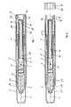
- FIG. 1depicts one embodiment of an injection device in accordance with the present invention, an automatic injector in an initial state, in which a drive unit of the injector is tensed and secured,
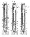
- FIG. 2shows injection device of FIG. 1 with the drive unit tensed but unlocked
- FIG. 3shows the injection device of FIG. 1 positioned on an injection site directly before piercing by an injection cannula
- FIG. 4illustrates injection device of FIG. 1 immediately after piercing by the injection cannula and immediately before dispensing the product
- FIG. 5shows the injection device of FIG. 1 with the inserted injection cannula after dispensing the product
- FIG. 6shows the injection device of FIG. 1 after use
- FIG. 7illustrates a proximal or rear part of a modified automatic injector in accordance with the present invention.
- FIG. 1illustrates an embodiment of an injection device in accordance with the present invention, wherein the device is an automatic injector.
- the injectoris depicted in section through a longitudinal plane, which has a central axis of symmetry L of the injector, which is referred to below as longitudinal axis L.
- a casing structure 1forms a main part of a housing of the injector.
- the casing structure 1serves as a means of holding the injector and mounting its components.
- the casing structure 1is a circular cylindrical sleeve with the longitudinal axis L as its axis of symmetry.
- a support structureis accommodated in the casing structure 1 , which can be displaced relative to the casing structure 1 along the longitudinal axis L.
- the support structurecomprises two parts and consists of a distal part 5 and a proximal part 7 , which are connected to one another so that they are unable to move axially relative to one another.
- the support structure as a wholeis a generally hollow cylinder in the embodiment illustrated, but other configuration are possible.
- a container 2 filled with an injectable productis accommodated in the support structure so as to be axially displaceable relative to the support structure in a forward-drive direction V.
- the container 2is an ampoule.
- the productis in the container 2 , mounted between an outlet which the container 2 has at an end disposed at the front end (which also may be thought of as the injection, delivery, distal or needle or cannula carrying end) by reference to the forward-drive direction, and a plunger 3 , which is accommodated in the container 2 so that it can slide axially.
- Attached to the front end of the container 2is an injection cannula 4 , pointing in the forward-drive direction V.
- a dispensing movement of the plunger 3 in the forward-drive direction Vforces the product out of the container 2 and then dispenses it through the injection cannula 4 .
- the dispensing movement of the plunger 3is generated by means of a drive unit.
- the drive unitconsists of a mechanical spring 15 and a plunger rod 16 .
- the plunger rod 16forms a ram 17 , by means of which it pushes against the plunger 3 in the forward-drive direction V.
- the plunger rod 16has assumed an axial retained position, in which it is retained against the force of the tensed spring 15 acting in the forward-drive direction V. To this end, the plunger rod 16 is in a retaining engagement with the support structure.
- the support structureis in turn prevented from moving in the forward-drive direction V relative to the casing structure 1 due to a form fit.
- the form fitexists between a front edge of the proximal part 7 and a shoulder projecting inwardly from a casing internal surface of the casing structure 1 .
- a spring 22presses the support structure into this abutting contact with the casing structure 1 .
- the retaining engagement of the plunger rod 16exists directly between a retaining shoulder 18 of the plunger rod 16 and a complementary shoulder 8 a of the proximal part 7 of the support structure. At its proximal (or rear) end, the plunger rod 16 mergers into a wider conical region constituting the retaining shoulder 18 .
- the sleeve-shaped proximal part 7is axially slotted so that tab-type retaining elements 8 are formed, each with a free proximal end.
- the retaining elements 8are able to bend elastically.
- Each of the retaining elements 8forms one of the complementary shoulders 8 a for the retaining shoulder 18 at its free proximal end.
- the complementary shoulders 8 alie facing the retaining shoulder in the forward-drive direction.
- the retaining shoulder 18sits in direct abutting contact with the complementary shoulders 8 a.
- the blocking mechanism 10is connected to the casing structure 1 so that it can not be displaced axially. In the exemplary embodiment illustrated, it is inserted in the casing structure 1 through the open proximal end of the casing structure 1 and latches with the casing structure 1 .
- the blocking mechanism 10is a sleeve body and surrounds the retaining elements 8 and blocks the retaining elements 8 in the retaining engagement, insofar as it prevents the retaining elements 8 from flexing radially outwards under the pressure exerted by the spring 15 via the retaining shoulder 18 .
- the retaining elements 8are thicker radially towards the exterior at their free proximal ends, so that they are bent against a radially facing, oppositely lying blocking surface of the blocking mechanism 10 radially inwards into the retaining engagement.
- the blocking surfaceis a casing internal face of the blocking mechanism 10 .
- the spring 15a compression spring in the illustrated embodiment, is placed under pressure between a proximal spring support 9 and the ram 17 , which therefore forms a distal spring support.
- the spring 15extends from the proximal spring support 9 into the proximally open container 2 and projects virtually as far as the plunger 3 . Its distal end is spaced axially apart from the rear face of the plunger 3 by only the thickness of the ram 17 .
- the ram 17in turn forms a thin, flat base of the plunger rod 16 pointing radially towards the longitudinal axis L.
- the spring 15is therefore applied as closely as possible against the plunger in order to obtain a drive unit and ultimately an injector with as short as possible an axial length.
- the ram 17ideally has a thickness which is precisely that needed to support the tensed spring 15 .
- the lower limit for the thickness of the spring support formed by the ram 17may, therefore, be pre-defined solely by the actual strength needed and a bit extra needed for safety reasons.
- the plunger rod 16is a metal sleeve. With a slimmer wall thickness, metal sleeves are stronger than plastic parts.
- the spring 15 lying against the sleeve shaft of the plunger rod 16 and guided by the sleeve shaftmay be of a correspondingly thicker design.
- the spring stiffness and hence the spring force exerted during the forward-driving actionmay advantageously be higher than is the case with thick-walled sleeves.
- sleeves with a slimmer wall thicknessmay be preferred for the plunger rod 16 .
- the plunger rod 16may be designed with a correspondingly larger external circumference. If the hollow cross-section of the container 2 exceeds a specific size, the plunger rod may 16 may also be a plastic sleeve in the embodiment where a sleeve is used.
- the plunger rod 16is a metal sleeve deep-drawn from a plate-type semi-finished product. It extends axially from the plunger 3 almost as far as the spring support 9 , and is spaced apart from the spring support 9 by only the axial distance needed for the engagement of the complementary shoulders 8 a . When the spring 15 is in the tensed state, the spring 15 and the plunger rod 16 are therefore essentially of the same axial length.
- the spring support 9 in the form of the sleeve baseconstitutes the end of the support structure.
- the housing of the injector formed by the casing structure 1 and the blocking mechanism 10are terminated by a locking element 13 , which, in the embodiment illustrated as an example, is a locking cap.
- the locking element 13is detachably secured to the blocking mechanism 10 by means of a catch system. It can be removed by the user by hand in order to unlock the injector and thus “arm it” in readiness for administering the product.
- an axially projecting web 14 of the locking element 13prolongs the blocking surface of the blocking mechanism 10 in the proximal direction.
- FIG. 2illustrates the automatic injector in the unlocked and hence “armed” state after the locking element 13 has been removed.
- Removing the locking element 13exposes a recess 11 of the blocking mechanism 10 .
- the recess 11is formed proximally in an axial extension of the blocking surface of the blocking mechanism 10 .
- the blocking mechanism 10becomes wider in the forward-drive direction V from its blocking surface via a shoulder 12 into the recess 11 .
- the shoulder 12forms an abrupt transition from a distal portion forming the blocking surface to a proximal portion of the blocking mechanism 10 forming the recess 11 .
- the web 14 of the locking element 13is an annular web, which fills the portion of the blocking mechanism 10 forming the recess 11 up to the radial height of the blocking surface in the fitted state.
- the support structure as a wholecan be displaced relative to the casing structure 1 and the blocking mechanism 10 can be moved in the direction opposite the forward-drive direction V so that the retaining elements 8 move with their free proximal ends behind the shoulder 12 into the recess 11 , where they can be moved radially outwards out of the retaining engagement.
- the travel length l of the backwards movement needed to achieve thisis pre-defined by an abutment surface of the blocking mechanism 10 pointing in the forward-drive direction V and an axially facing complementary abutment surface of the proximal part 7 pointing in the direction opposite the forward-drive direction V.
- a needle guard 21projects into the casing structure 1 , which is likewise open.
- the casing structure 1provides a mount for or carries the needle guard 21 so that it can be axially displaced.
- the spring 22which is supported on the casing structure 1 on the one hand and on the needle guard 21 on the other, biases the needle guard into a distal position relative to the casing structure 1 .
- the spring 22therefore pushes the needle guard 21 against a stop formed by the support structure.
- the support structurehas an outwardly bendable blocking element 6 , integrally formed from the distal part 5 in the form of a sort of tongue projecting in the forward-drive direction V.
- the purpose of the blocking element 6after administering the product, is to block the needle guard 21 in its protective position, i.e., in its distal or forward position relative to the casing structure 1 , and thus protect the user from the injection cannula 4 .
- a cannula cover 20is placed on the distal end of the container 2 and over the injection cannula 4 .
- the cannula cover 20positions the container 2 in the support structure and has the requisite stiffness for this purpose. Furthermore, it helps keeps the injection cannula sterile. On the other hand, however, its axial stiffness is not so great that it could hamper or even prevent the forward driving action of the container 2 in the support structure once the injector has been triggered.
- the needle cover 20may be an axially flexible rubber sleeve or a bellows, for example.
- the injectormay be issued to the user in the initial state, the state as sold, illustrated in FIG. 1 .
- the container 2is filled with exactly the quantity of product required for one injection beforehand.
- the drive unitis loaded, i.e., the plunger rod 16 is disposed in the retaining engagement and the spring 15 is tensed.
- the userBy removing the locking element 13 from the blocking mechanism 10 , the user unlocks the injector, which is then in the unlocked state illustrated in FIG. 2 .
- the injector together with the needle guard 20is placed vertically on the skin at the desired injection site and pressed against the skin.
- the casing structure 1serves as a manual grip for this purpose.
- the needle guard 21is moved against the force of the spring 22 deeper into the casing structure 1 in a first phase of the contact pressure.
- the needle guard 21 and the support structureare jointly moved opposite the forward-drive direction V relative to the casing structure 1 .
- the retaining elements 8slide on the blocking surface of the blocking mechanism 10 in the proximal direction, finally reaching the region of the recess 11 .
- the relative movementis restricted by the support structure coming into contact with the blocking mechanism 10 .
- the retaining elements 8flex radially outwards into the recess 11 due to the force exerted by the spring 15 via the retaining shoulder 18 so that the retaining engagement is released.
- the flexing movement of the retaining elements 8is assisted by their natural elastic rebound forces.
- the retaining shoulder 18 and/or the complementary shoulders 8 apoint at an angle to the longitudinal axis L so that they are able to slide on one another as soon as the retaining elements 8 are able to flex into the recess 11 .
- Jammingis at least prevented by an inclined contour of the retaining shoulder 18 and/or the complementary shoulders 8 a.
- FIG. 3illustrates the injector in the state immediately after the retaining engagement has been released and before the onset of the forward-driving movement of the plunger rod 16 .
- the plunger rod 16switches due to the pressure of spring 15 immediately from this transition state to the forward-driving movement.
- the support structureis retained in its proximal position relative to the casing structure 1 due to the contact pressure of the injector on the skin.
- the plunger rod 16presses against the plunger 3 with its ram 17 . Due to the static friction between the plunger 3 and the container 2 , the container 2 moves in the support structure in the forward-drive direction V.
- the injection cannula 4moves in conjunction with the container 2 , piercing the cannula cover 20 during the course of this piercing movement, so that it is then inserted in the skin and, in some preferred embodiments, the tissue underneath the skin.
- the container 2is pushed past the blocking element 6 and is bent outwards as a result.
- the cannula cover 20is also compressed.
- the cannula cover 20restricts the piercing movement and hence the penetration depth of the injection cannula 4 .
- FIG. 4illustrates the injector after the piercing movement but before the product has been dispensed.
- the piercing movement of the plunger rod 16switches to the dispensing movement during which the product is dispensed at the latest after the injection cannula 4 has completed the piercing movement.
- the piercing movement of the injection cannula 4is terminated before the plunger 3 starts the dispensing movement.
- the plunge rod 16causes both movements due to its own forward-drive movement.
- the spring 15constitutes a piercing and dispensing spring.
- FIG. 5illustrates the injector after the container 2 has been completely emptied, i.e., after the dispensing process has been terminated but before the injection cannula 4 has been pulled out of the tissue.
- the needle guard 21moves in the forward-drive direction V relative to the casing structure 1 due to the force of the spring 22 .
- the needle guard 21is moved in the forward-drive direction V back in front of the blocking element 6 by means of a stop shoulder.
- the blocking element 6 and the relevant stop shoulder of the needle guard 21then lie axially opposite one another so that the blocking element 6 prevents the needle guard 21 from being retracted again and blocks the needle guard 21 in its protective position.
- FIG. 6illustrates the injector after use with the blocked needle guard 21 .
- the injectormay be designed as a disposable device and is disposed of once it has been used.
- FIG. 7illustrates the proximal portion of a modified automatic injector, which differs from the injection device illustrated in FIGS. 1 to 6 due to the ram of the plunger rod 16 and the retaining engagement between the plunger rod 16 and the support structure.
- the ram 17 ′ of the modified embodimentillustrated as an example, is not formed by the sleeve shaft of the plunger rod 16 as a continuous base, but as a peripheral annular shoulder.
- the plunger rod 16 of the modified embodimentis again a metal sleeve. However, it is made by re-shaping a tubular piece.
- the sleeve shaftis the tubular piece in its not warped form.
- the ram 17 ′ and the retaining shoulder 18are respectively formed by a bending process, the ram 17 ′ by pressing on a hollow die and the retaining shoulder by pressing against a widening die.
- the retaining engagementis not obtained between the retaining shoulder 18 and the support structure but by means of one, or in the embodiment illustrated, by several transmitting elements 19 .
- the transmitting elements 19might be ball bearings or cylindrical pins, for example, which are pressed in the forward-drive direction V by the spring 15 via the retaining shoulder 18 against a complementary shoulder of the support structure.
- the retaining engagementis released in the same way as that of the device illustrated in FIGS. 1 to 6 , the only difference being that it is the transmitting elements 19 which flex into the recess 11 of the blocking mechanism 10 rather than a retaining element 8 formed by the support structure.
Landscapes
- Health & Medical Sciences (AREA)
- Vascular Medicine (AREA)
- Engineering & Computer Science (AREA)
- Anesthesiology (AREA)
- Biomedical Technology (AREA)
- Heart & Thoracic Surgery (AREA)
- Hematology (AREA)
- Life Sciences & Earth Sciences (AREA)
- Animal Behavior & Ethology (AREA)
- General Health & Medical Sciences (AREA)
- Public Health (AREA)
- Veterinary Medicine (AREA)
- Infusion, Injection, And Reservoir Apparatuses (AREA)
Abstract
Description
Claims (23)
Applications Claiming Priority (4)
| Application Number | Priority Date | Filing Date | Title |
|---|---|---|---|
| DE10351594.1 | 2003-11-05 | ||
| DE10351594ADE10351594A1 (en) | 2003-11-05 | 2003-11-05 | Device for the administration of an injectable product |
| DE10351594 | 2003-11-05 | ||
| PCT/CH2004/000645WO2005044344A1 (en) | 2003-11-05 | 2004-10-28 | Device for the administration of an injectable product |
Related Parent Applications (1)
| Application Number | Title | Priority Date | Filing Date |
|---|---|---|---|
| PCT/CH2004/000645ContinuationWO2005044344A1 (en) | 2003-11-05 | 2004-10-28 | Device for the administration of an injectable product |
Publications (2)
| Publication Number | Publication Date |
|---|---|
| US20060264830A1 US20060264830A1 (en) | 2006-11-23 |
| US8591465B2true US8591465B2 (en) | 2013-11-26 |
Family
ID=34559341
Family Applications (1)
| Application Number | Title | Priority Date | Filing Date |
|---|---|---|---|
| US11/417,518Active2027-12-09US8591465B2 (en) | 2003-11-05 | 2006-05-04 | Device for administering an injectable product |
Country Status (7)
| Country | Link |
|---|---|
| US (1) | US8591465B2 (en) |
| EP (1) | EP1684830A1 (en) |
| JP (1) | JP2007509657A (en) |
| CN (1) | CN1878587A (en) |
| AU (1) | AU2004286732B2 (en) |
| DE (1) | DE10351594A1 (en) |
| WO (1) | WO2005044344A1 (en) |
Cited By (34)
| Publication number | Priority date | Publication date | Assignee | Title |
|---|---|---|---|---|
| US9415176B1 (en) | 2015-01-22 | 2016-08-16 | West Pharmaceutical Services, Inc. | Autoinjector having an end-of-dose visual indicator |
| US9511189B2 (en) | 2011-09-02 | 2016-12-06 | Unitract Syringe Pty Ltd | Insertion mechanism for a drug delivery pump |
| US9707335B2 (en) | 2011-09-02 | 2017-07-18 | Unitract Syringe Pty Ltd | Drive mechanism for drug delivery pumps with integrated status indication |
| US9707337B2 (en) | 2011-09-13 | 2017-07-18 | Unitract Syringe Pty Ltd | Sterile fluid pathway connection to drug containers for drug delivery pumps |
| US9737655B2 (en) | 2013-08-23 | 2017-08-22 | Unitract Syringe Pty Ltd | Integrated pierceable seal fluid pathway connection and drug containers for drug delivery pumps |
| US9802030B2 (en) | 2013-01-25 | 2017-10-31 | Unl Holdings Llc | Integrated sliding seal fluid pathway connection and drug containers for drug delivery pumps |
| US9814832B2 (en) | 2011-09-02 | 2017-11-14 | Unl Holdings Llc | Drive mechanism for drug delivery pumps with integrated status indication |
| US9925336B2 (en) | 2008-05-20 | 2018-03-27 | Avant Medical Corp. | Cassette for a hidden injection needle |
| US9974904B2 (en) | 2008-05-20 | 2018-05-22 | Avant Medical Corp. | Autoinjector system |
| US9999727B2 (en) | 2011-09-02 | 2018-06-19 | Unl Holdings Llc | Drive mechanism for drug delivery pumps with integrated status indication |
| US10092706B2 (en) | 2011-04-20 | 2018-10-09 | Amgen Inc. | Autoinjector apparatus |
| US10092703B2 (en) | 2013-03-15 | 2018-10-09 | Amgen Inc. | Drug cassette, autoinjector, and autoinjector system |
| US10251996B2 (en) | 2012-08-29 | 2019-04-09 | Unl Holdings Llc | Variable rate controlled delivery drive mechanisms for drug delivery pumps |
| US10357619B1 (en) | 2018-02-08 | 2019-07-23 | Chalbourne Brasington | Auto-injection device |
| US10492990B2 (en) | 2013-03-15 | 2019-12-03 | Amgen Inc. | Drug cassette, autoinjector, and autoinjector system |
| US10549044B2 (en) | 2016-06-09 | 2020-02-04 | Becton, Dickinson And Company | Spacer assembly for drug delivery system |
| US10603445B2 (en) | 2016-06-09 | 2020-03-31 | Becton, Dickinson And Company | Needle actuator assembly for drug delivery system |
| US10639422B2 (en) | 2008-07-23 | 2020-05-05 | Avant Medical Corp. | System and method for an injection using a syringe needle |
| USD886986S1 (en) | 2013-03-12 | 2020-06-09 | Unl Holdings Llc | Drug delivery pump |
| US10751476B2 (en) | 2016-06-09 | 2020-08-25 | Becton, Dickinson And Company | Actuator assembly for drug delivery system |
| US10792432B2 (en) | 2016-06-09 | 2020-10-06 | Becton, Dickinson And Company | Drive assembly and spacer for drug delivery system |
| USD898908S1 (en) | 2012-04-20 | 2020-10-13 | Amgen Inc. | Pharmaceutical product cassette for an injection device |
| US10806855B2 (en) | 2014-09-29 | 2020-10-20 | Unl Holdings Llc | Rigid needle insertion mechanism for a drug delivery pump |
| WO2021067208A1 (en)* | 2019-09-30 | 2021-04-08 | Amgen Inc. | Drug delivery device |
| US11033676B2 (en) | 2016-08-08 | 2021-06-15 | Unl Holdings Llc | Drug delivery device and method for connecting a fluid flowpath |
| US11173244B2 (en) | 2011-09-02 | 2021-11-16 | Unl Holdings Llc | Drive mechanism for drug delivery pumps with integrated status indication |
| US11207384B2 (en)* | 2017-06-01 | 2021-12-28 | Eli Lilly And Company | Rapid-acting insulin compositions |
| US11266792B2 (en) | 2019-10-28 | 2022-03-08 | FGC Holdings Limited | Single use safety needle guard |
| US11357918B2 (en) | 2017-10-16 | 2022-06-14 | Becton, Dickinson And Company | Spacer assembly for drug delivery device |
| US11623051B2 (en) | 2003-09-17 | 2023-04-11 | E3D Agricultural Cooperative Association Ltd. | Automatic injection device |
| US11850401B2 (en) | 2018-06-08 | 2023-12-26 | Antares Pharma, Inc. | Auto-insert injector |
| US12097357B2 (en) | 2008-09-15 | 2024-09-24 | West Pharma. Services IL, Ltd. | Stabilized pen injector |
| US12208245B2 (en) | 2019-09-30 | 2025-01-28 | Amgen Inc. | Drug delivery device |
| US12440625B2 (en) | 2020-09-29 | 2025-10-14 | Amgen Inc. | Drug delivery device |
Families Citing this family (31)
| Publication number | Priority date | Publication date | Assignee | Title |
|---|---|---|---|---|
| US9486581B2 (en)* | 2002-09-11 | 2016-11-08 | Becton, Dickinson And Company | Injector device with force lock-out and injection rate limiting mechanisms |
| CH696421A5 (en) | 2003-12-18 | 2007-06-15 | Tecpharma Licensing Ag | Autoinjector with arresting the drug container. |
| GB0427891D0 (en)* | 2004-12-21 | 2005-01-19 | Owen Mumford Ltd | Skin pricking apparatus |
| FR2899482A1 (en)* | 2006-04-11 | 2007-10-12 | Becton Dickinson France Soc Pa | Automatic medicament/product injection device for patient, has safety shield coupled to housing, and provided in active state at end of needle insertion step before which product/medicament injection step is not started |
| CA2653401A1 (en) | 2006-05-29 | 2007-12-06 | Novo Nordisk A/S | Mechanism for injection device |
| EP2129414A1 (en)* | 2007-03-22 | 2009-12-09 | Tecpharma Licensing AG | Injection device having trigger safety devices |
| DE102007030327A1 (en) | 2007-06-29 | 2009-01-02 | Tecpharma Licensing Ag | Injection device with a spring for a needle protection sleeve |
| DE102007031630B3 (en)* | 2007-07-06 | 2008-12-24 | Lts Lohmann Therapie-Systeme Ag | Disposable injector with at least one support rod |
| DE102007031714A1 (en)* | 2007-07-06 | 2009-01-08 | Lts Lohmann Therapie-Systeme Ag | Disposable injector with at least one push rod and a cap |
| DE102008003105A1 (en)* | 2008-01-01 | 2009-07-02 | Lts Lohmann Therapie-Systeme Ag | Disposable injector with manually operated piston and a two-chamber system |
| GB0801874D0 (en)* | 2008-02-01 | 2008-03-12 | Liversidge Barry P | Injection device |
| DE102008037310B4 (en)* | 2008-08-11 | 2023-11-16 | Ypsomed Ag | Automatic injection device for administering a fixed dose |
| GB0814747D0 (en)* | 2008-08-13 | 2008-09-17 | Owen Mumford Ltd | Autoinjection devices |
| DE102008048595A1 (en)* | 2008-09-23 | 2010-04-01 | Lts Lohmann Therapie-Systeme Ag | Disposable injector with high injection safety |
| US8979807B2 (en)* | 2008-09-29 | 2015-03-17 | Becton Dickinson France | Automatic injection device with audible indicator of completed injection |
| WO2010035057A1 (en)* | 2008-09-29 | 2010-04-01 | Becton Dickinson France | Autoinjector with audible indication of completed delivery |
| DE102008063519A1 (en)* | 2008-12-18 | 2010-07-01 | Lts Lohmann Therapie-Systeme Ag | Disposable injector with a flexurally elastic metal housing |
| DE102008063518A1 (en) | 2008-12-18 | 2010-07-01 | Lts Lohmann Therapie-Systeme Ag | Pumpable disposable injector with a flexurally elastic housing |
| DE102008063517A1 (en) | 2008-12-18 | 2010-07-01 | Lts Lohmann Therapie-Systeme Ag | Disposable injector with a flexurally elastic housing II |
| JP5732039B2 (en) | 2009-03-20 | 2015-06-10 | アンタレス・ファーマ・インコーポレーテッド | Hazardous drug injection system |
| EP2583708B1 (en)* | 2010-03-31 | 2023-02-22 | SHL Medical AG | Medicament delivery device comprising feedback signalling means |
| EP2624882B1 (en) | 2010-10-06 | 2021-04-28 | Ypsomed AG | Locking and retaining mechanism for the needle guard sleeve of an injection device |
| CA2922441C (en)* | 2013-08-29 | 2018-07-17 | Carebay Europe Ltd | Medicament delivery device |
| US10799634B2 (en) | 2014-11-12 | 2020-10-13 | Novo Nordisk A/S | Method of manufacturing one of a range of autoinjectors |
| WO2017017229A1 (en)* | 2015-07-30 | 2017-02-02 | F+K Innovationen Gmbh & Co.Kg | Syringe |
| JP6883577B2 (en)* | 2015-11-19 | 2021-06-09 | ノボ・ノルデイスク・エー/エス | Shielded needle cannula |
| FR3057169B1 (en)* | 2016-10-11 | 2022-04-01 | Crossject | INJECTION NOZZLE FOR NEEDLELESS INJECTION DEVICE |
| AT519383B1 (en) | 2016-10-27 | 2018-09-15 | Pharma Consult Gmbh | Injection device, in particular autoinjector, for the simultaneous delivery of several drugs |
| RU2708948C1 (en)* | 2019-04-02 | 2019-12-12 | Акционерное общество "Конструкторское бюро химавтоматики" (АО КБХА) | Hydraulic needle-less injector |
| WO2021067990A1 (en)* | 2019-09-30 | 2021-04-08 | Amgen Inc. | Drug delivery device |
| CN113117191A (en)* | 2021-05-13 | 2021-07-16 | 深圳惠迈智能科技有限公司 | Automatic injection pen |
Citations (6)
| Publication number | Priority date | Publication date | Assignee | Title |
|---|---|---|---|---|
| US4316463A (en)* | 1981-01-26 | 1982-02-23 | Vac-O-Cast, Inc. | Corrosive protected hypodermic module |
| US5695472A (en)* | 1993-05-27 | 1997-12-09 | Washington Biotech Corporation | Modular automatic or manual emergency medicine injection system |
| WO2002047746A1 (en)* | 2000-12-14 | 2002-06-20 | Shl Medical Ab | Auto-injector |
| WO2003070296A2 (en) | 2002-02-15 | 2003-08-28 | Antares Pharma, Inc. | Injector with bypass channel |
| US20030171717A1 (en) | 2000-06-08 | 2003-09-11 | Gianrico Farrugia | Automated injection device for administration of liquid medicament |
| US6805686B1 (en)* | 2003-05-06 | 2004-10-19 | Abbott Laboratories | Autoinjector with extendable needle protector shroud |
Family Cites Families (12)
| Publication number | Priority date | Publication date | Assignee | Title |
|---|---|---|---|---|
| US2784773A (en) | 1953-11-23 | 1957-03-12 | David L Rowland | Weatherproof cushion |
| GB1206340A (en)* | 1966-06-13 | 1970-09-23 | Secr Defence | Improvements in or relating to hypodermic injection apparatus |
| DE1957833A1 (en)* | 1968-11-21 | 1970-07-02 | Maurice Steiner | Injection syringe, especially injection syringe handled by the patient himself |
| BE755224A (en)* | 1969-08-25 | 1971-02-24 | Philips Nv | INJECTION SYRINGE |
| US4258713A (en)* | 1979-07-23 | 1981-03-31 | Wardlaw Stephen C | Automatic disposable hypodermic syringe |
| DE3916454A1 (en) | 1989-05-20 | 1990-11-22 | Gerhard Kuehnemuth | Cushion for garden chair - consists of layers of padding between textile sheets sewn together around their edges |
| HU200699B (en)* | 1989-07-05 | 1990-08-28 | Gyula Erdelyi | Neddleless hypodermic syringe particularly for blinds and poor-sighted persons |
| US5868711A (en)* | 1991-04-29 | 1999-02-09 | Board Of Regents, The University Of Texas System | Implantable intraosseous device for rapid vascular access |
| FR2733155B1 (en)* | 1995-04-18 | 1997-09-19 | Tebro | RECHARGEABLE SELF-INJECTOR |
| DE19822031C2 (en)* | 1998-05-15 | 2000-03-23 | Disetronic Licensing Ag | Auto injection device |
| FR2815543B1 (en)* | 2000-10-19 | 2003-10-24 | Sedat | SELF-INJECTION SYRINGE OF AN EXTEMPORANEOUS MIXTURE |
| DE10206910A1 (en)* | 2002-02-19 | 2003-09-04 | Disetronic Licensing Ag | Device for administering an injectable product |
- 2003
- 2003-11-05DEDE10351594Apatent/DE10351594A1/ennot_activeWithdrawn
- 2004
- 2004-10-28CNCNA2004800327817Apatent/CN1878587A/enactivePending
- 2004-10-28EPEP04789818Apatent/EP1684830A1/ennot_activeWithdrawn
- 2004-10-28WOPCT/CH2004/000645patent/WO2005044344A1/enactiveApplication Filing
- 2004-10-28JPJP2006537028Apatent/JP2007509657A/ennot_activeCeased
- 2004-10-28AUAU2004286732Apatent/AU2004286732B2/ennot_activeCeased
- 2006
- 2006-05-04USUS11/417,518patent/US8591465B2/enactiveActive
Patent Citations (7)
| Publication number | Priority date | Publication date | Assignee | Title |
|---|---|---|---|---|
| US4316463A (en)* | 1981-01-26 | 1982-02-23 | Vac-O-Cast, Inc. | Corrosive protected hypodermic module |
| US5695472A (en)* | 1993-05-27 | 1997-12-09 | Washington Biotech Corporation | Modular automatic or manual emergency medicine injection system |
| US20030171717A1 (en) | 2000-06-08 | 2003-09-11 | Gianrico Farrugia | Automated injection device for administration of liquid medicament |
| WO2002047746A1 (en)* | 2000-12-14 | 2002-06-20 | Shl Medical Ab | Auto-injector |
| US20040039336A1 (en)* | 2000-12-14 | 2004-02-26 | Mikael Amark | Auto-injector |
| WO2003070296A2 (en) | 2002-02-15 | 2003-08-28 | Antares Pharma, Inc. | Injector with bypass channel |
| US6805686B1 (en)* | 2003-05-06 | 2004-10-19 | Abbott Laboratories | Autoinjector with extendable needle protector shroud |
Cited By (66)
| Publication number | Priority date | Publication date | Assignee | Title |
|---|---|---|---|---|
| US11623051B2 (en) | 2003-09-17 | 2023-04-11 | E3D Agricultural Cooperative Association Ltd. | Automatic injection device |
| US10864324B2 (en) | 2008-05-20 | 2020-12-15 | Avant Medical Corp. | Autoinjector system |
| US10792426B2 (en) | 2008-05-20 | 2020-10-06 | Avant Medical Corp. | Autoinjector system |
| US11883633B2 (en) | 2008-05-20 | 2024-01-30 | Avant Medical Corp. | Autoinjector system |
| US9925336B2 (en) | 2008-05-20 | 2018-03-27 | Avant Medical Corp. | Cassette for a hidden injection needle |
| US9974904B2 (en) | 2008-05-20 | 2018-05-22 | Avant Medical Corp. | Autoinjector system |
| US12186535B2 (en) | 2008-07-23 | 2025-01-07 | Avant Medical Corp. | System and method for an injection using a syringe needle |
| US11724032B2 (en) | 2008-07-23 | 2023-08-15 | Avant Medical Corp. | System and method for an injection using a syringe needle |
| US10639422B2 (en) | 2008-07-23 | 2020-05-05 | Avant Medical Corp. | System and method for an injection using a syringe needle |
| US12097357B2 (en) | 2008-09-15 | 2024-09-24 | West Pharma. Services IL, Ltd. | Stabilized pen injector |
| US11986643B2 (en) | 2011-04-20 | 2024-05-21 | Amgen Inc. | Autoinjector apparatus |
| US10918805B2 (en) | 2011-04-20 | 2021-02-16 | Amgen Inc. | Autoinjector apparatus |
| US10092706B2 (en) | 2011-04-20 | 2018-10-09 | Amgen Inc. | Autoinjector apparatus |
| US11419990B2 (en) | 2011-04-20 | 2022-08-23 | Amgen Inc. | Autoinjector apparatus |
| US12350480B2 (en) | 2011-04-20 | 2025-07-08 | Amgen Inc. | Autoinjector apparatus |
| US10806854B2 (en) | 2011-09-02 | 2020-10-20 | Unl Holdings Llc | Insertion mechanism for a drug delivery pump |
| US9999727B2 (en) | 2011-09-02 | 2018-06-19 | Unl Holdings Llc | Drive mechanism for drug delivery pumps with integrated status indication |
| US10322231B2 (en) | 2011-09-02 | 2019-06-18 | UNL Holdings | Drive mechanism for drug delivery pumps with integrated status indication |
| US10549029B2 (en) | 2011-09-02 | 2020-02-04 | Unl Holdings Llc | Drive mechanism for drug delivery pumps with integrated status indication |
| US9814832B2 (en) | 2011-09-02 | 2017-11-14 | Unl Holdings Llc | Drive mechanism for drug delivery pumps with integrated status indication |
| US11173244B2 (en) | 2011-09-02 | 2021-11-16 | Unl Holdings Llc | Drive mechanism for drug delivery pumps with integrated status indication |
| US10918788B2 (en) | 2011-09-02 | 2021-02-16 | Unl Holdings Llc | Drive mechanism for drug delivery pumps with integrated status indication |
| US9511189B2 (en) | 2011-09-02 | 2016-12-06 | Unitract Syringe Pty Ltd | Insertion mechanism for a drug delivery pump |
| US9707335B2 (en) | 2011-09-02 | 2017-07-18 | Unitract Syringe Pty Ltd | Drive mechanism for drug delivery pumps with integrated status indication |
| US11484644B2 (en) | 2011-09-13 | 2022-11-01 | Unl Holdings Llc | Sterile fluid pathway connection to drug containers for drug delivery pumps |
| US9707337B2 (en) | 2011-09-13 | 2017-07-18 | Unitract Syringe Pty Ltd | Sterile fluid pathway connection to drug containers for drug delivery pumps |
| US10369274B2 (en) | 2011-09-13 | 2019-08-06 | Unl Holdings Llc | Sterile fluid pathway connection to drug containers for drug delivery pumps |
| USD898908S1 (en) | 2012-04-20 | 2020-10-13 | Amgen Inc. | Pharmaceutical product cassette for an injection device |
| USD1076075S1 (en) | 2012-04-20 | 2025-05-20 | Amgen Inc. | Pharmaceutical product cassette for an injection device |
| US10251996B2 (en) | 2012-08-29 | 2019-04-09 | Unl Holdings Llc | Variable rate controlled delivery drive mechanisms for drug delivery pumps |
| US10933189B2 (en) | 2012-08-29 | 2021-03-02 | Unl Holdings Llc | Variable rate controlled delivery drive mechanisms for drug delivery pumps |
| US10994114B2 (en) | 2013-01-25 | 2021-05-04 | Unl Holdings Llc | Integrated sliding seal fluid pathway connection and drug containers for drug delivery pumps |
| US9802030B2 (en) | 2013-01-25 | 2017-10-31 | Unl Holdings Llc | Integrated sliding seal fluid pathway connection and drug containers for drug delivery pumps |
| USD886986S1 (en) | 2013-03-12 | 2020-06-09 | Unl Holdings Llc | Drug delivery pump |
| US10492990B2 (en) | 2013-03-15 | 2019-12-03 | Amgen Inc. | Drug cassette, autoinjector, and autoinjector system |
| US10092703B2 (en) | 2013-03-15 | 2018-10-09 | Amgen Inc. | Drug cassette, autoinjector, and autoinjector system |
| US11020537B2 (en) | 2013-03-15 | 2021-06-01 | Amgen Inc. | Drug cassette, autoinjector, and autoinjector system |
| US11944798B2 (en) | 2013-03-15 | 2024-04-02 | Amgen Inc. | Drug cassette, autoinjector, and autoinjector system |
| US10786629B2 (en) | 2013-03-15 | 2020-09-29 | Amgen Inc. | Drug cassette, autoinjector, and autoinjector system |
| US9737655B2 (en) | 2013-08-23 | 2017-08-22 | Unitract Syringe Pty Ltd | Integrated pierceable seal fluid pathway connection and drug containers for drug delivery pumps |
| US11040135B2 (en) | 2013-08-23 | 2021-06-22 | Unl Holdings Llc | Integrated pierceable seal fluid pathway connection and drug containers for drug delivery pumps |
| US10806855B2 (en) | 2014-09-29 | 2020-10-20 | Unl Holdings Llc | Rigid needle insertion mechanism for a drug delivery pump |
| US9415176B1 (en) | 2015-01-22 | 2016-08-16 | West Pharmaceutical Services, Inc. | Autoinjector having an end-of-dose visual indicator |
| US11857769B2 (en) | 2016-06-09 | 2024-01-02 | Becton, Dickinson And Company | Drive assembly and spacer for drug delivery system |
| US11904148B2 (en) | 2016-06-09 | 2024-02-20 | Becton, Dickinson And Company | Actuator assembly for drug delivery system |
| US11654248B2 (en) | 2016-06-09 | 2023-05-23 | Becton, Dickinson And Company | Needle actuator assembly for drug delivery system |
| US10751476B2 (en) | 2016-06-09 | 2020-08-25 | Becton, Dickinson And Company | Actuator assembly for drug delivery system |
| US12329950B2 (en) | 2016-06-09 | 2025-06-17 | Becton, Dickinson And Company | Needle actuator assembly for drug delivery system |
| US10792432B2 (en) | 2016-06-09 | 2020-10-06 | Becton, Dickinson And Company | Drive assembly and spacer for drug delivery system |
| US10603445B2 (en) | 2016-06-09 | 2020-03-31 | Becton, Dickinson And Company | Needle actuator assembly for drug delivery system |
| US12053620B2 (en) | 2016-06-09 | 2024-08-06 | Becton, Dickinson And Company | Spacer assembly for drug delivery system |
| US10549044B2 (en) | 2016-06-09 | 2020-02-04 | Becton, Dickinson And Company | Spacer assembly for drug delivery system |
| US11033676B2 (en) | 2016-08-08 | 2021-06-15 | Unl Holdings Llc | Drug delivery device and method for connecting a fluid flowpath |
| US11207384B2 (en)* | 2017-06-01 | 2021-12-28 | Eli Lilly And Company | Rapid-acting insulin compositions |
| US12201817B2 (en) | 2017-10-16 | 2025-01-21 | Becton, Dickinson And Company | Spacer assembly for drug delivery device |
| US11357918B2 (en) | 2017-10-16 | 2022-06-14 | Becton, Dickinson And Company | Spacer assembly for drug delivery device |
| US10357619B1 (en) | 2018-02-08 | 2019-07-23 | Chalbourne Brasington | Auto-injection device |
| US11850401B2 (en) | 2018-06-08 | 2023-12-26 | Antares Pharma, Inc. | Auto-insert injector |
| US12208245B2 (en) | 2019-09-30 | 2025-01-28 | Amgen Inc. | Drug delivery device |
| WO2021067208A1 (en)* | 2019-09-30 | 2021-04-08 | Amgen Inc. | Drug delivery device |
| US12311151B2 (en) | 2019-09-30 | 2025-05-27 | Amgen Inc. | Drug delivery device |
| US11878149B2 (en) | 2019-09-30 | 2024-01-23 | Amgen Inc. | Drug delivery device |
| US11266792B2 (en) | 2019-10-28 | 2022-03-08 | FGC Holdings Limited | Single use safety needle guard |
| US12280248B2 (en) | 2019-10-28 | 2025-04-22 | FGC Holdings Limited | Single use safety needle guard |
| US11833337B2 (en) | 2019-10-28 | 2023-12-05 | FGC Holdings Limited | Single use safety needle guard |
| US12440625B2 (en) | 2020-09-29 | 2025-10-14 | Amgen Inc. | Drug delivery device |
Also Published As
| Publication number | Publication date |
|---|---|
| WO2005044344A1 (en) | 2005-05-19 |
| US20060264830A1 (en) | 2006-11-23 |
| AU2004286732A1 (en) | 2005-05-19 |
| JP2007509657A (en) | 2007-04-19 |
| DE10351594A1 (en) | 2005-06-16 |
| AU2004286732B2 (en) | 2009-05-14 |
| EP1684830A1 (en) | 2006-08-02 |
| CN1878587A (en) | 2006-12-13 |
Similar Documents
| Publication | Publication Date | Title |
|---|---|---|
| US8591465B2 (en) | Device for administering an injectable product | |
| EP1755708B1 (en) | Injection device | |
| US7749195B2 (en) | Administration device with an insertion mechanism and a delivery mechanism | |
| AU2004286736B2 (en) | Device for the administration of an injectable product | |
| US9446196B2 (en) | Auto-injector | |
| JP5990189B2 (en) | Automatic syringe | |
| EP2067496B1 (en) | Medical injector | |
| US6428528B2 (en) | Needle assisted jet injector | |
| JP5990188B2 (en) | Automatic syringe | |
| JP6080775B2 (en) | Automatic syringe | |
| EP1100566A1 (en) | Loading mechanism for medical injector assembly | |
| US20060224117A1 (en) | System for administering an injectable product | |
| JP2025102808A (en) | Dosing device for dosing a liquid | |
| EP4487887A1 (en) | Drive spring and needle cover spring for an injection device | |
| EP4616888A1 (en) | Safety mechanism for a drug delivery device | |
| CN116897060A (en) | Injection device | |
| KR20200118095A (en) | Injection device for injecting a composition contained within a medical container | |
| HK1212267B (en) | Injection device | |
| HK1156556B (en) | Injection device |
Legal Events
| Date | Code | Title | Description |
|---|---|---|---|
| AS | Assignment | Owner name:TECPHARMA LICENSING AG, SWITZERLAND Free format text:ASSIGNMENT OF ASSIGNORS INTEREST;ASSIGNOR:HOMMANN, EDGAR;REEL/FRAME:017968/0796 Effective date:20060621 | |
| STCF | Information on status: patent grant | Free format text:PATENTED CASE | |
| FPAY | Fee payment | Year of fee payment:4 | |
| AS | Assignment | Owner name:YPSOMED AG, SWITZERLAND Free format text:ASSIGNMENT OF ASSIGNORS INTEREST;ASSIGNOR:TECPHARMA LICESNING AG;REEL/FRAME:052984/0805 Effective date:20200617 | |
| AS | Assignment | Owner name:YPSOMED AG, SWITZERLAND Free format text:CORRECTIVE ASSIGNMENT TO CORRECT THE ASSIGNOR FROM TECPHARMA LICESNING AG TO TECPHARMA LICENSING AG PREVIOUSLY RECORDED ON REEL 052984 FRAME 0805. ASSIGNOR(S) HEREBY CONFIRMS THE THE ASSIGNMENT OF ASSIGNORS INTEREST;ASSIGNOR:TECPHARMA LICENSING AG;REEL/FRAME:053309/0648 Effective date:20200617 | |
| MAFP | Maintenance fee payment | Free format text:PAYMENT OF MAINTENANCE FEE, 8TH YEAR, LARGE ENTITY (ORIGINAL EVENT CODE: M1552); ENTITY STATUS OF PATENT OWNER: LARGE ENTITY Year of fee payment:8 | |
| FEPP | Fee payment procedure | Free format text:MAINTENANCE FEE REMINDER MAILED (ORIGINAL EVENT CODE: REM.); ENTITY STATUS OF PATENT OWNER: LARGE ENTITY |