US8591460B2 - Steerable catheter and dilator and system and method for implanting a heart implant - Google Patents
Steerable catheter and dilator and system and method for implanting a heart implantDownload PDFInfo
- Publication number
- US8591460B2 US8591460B2US12/510,929US51092909AUS8591460B2US 8591460 B2US8591460 B2US 8591460B2US 51092909 AUS51092909 AUS 51092909AUS 8591460 B2US8591460 B2US 8591460B2
- Authority
- US
- United States
- Prior art keywords
- catheter
- shaft
- steerable
- region
- actuator
- Prior art date
- Legal status (The legal status is an assumption and is not a legal conclusion. Google has not performed a legal analysis and makes no representation as to the accuracy of the status listed.)
- Active, expires
Links
Images


Classifications
- A—HUMAN NECESSITIES
- A61—MEDICAL OR VETERINARY SCIENCE; HYGIENE
- A61M—DEVICES FOR INTRODUCING MEDIA INTO, OR ONTO, THE BODY; DEVICES FOR TRANSDUCING BODY MEDIA OR FOR TAKING MEDIA FROM THE BODY; DEVICES FOR PRODUCING OR ENDING SLEEP OR STUPOR
- A61M25/00—Catheters; Hollow probes
- A61M25/01—Introducing, guiding, advancing, emplacing or holding catheters
- A61M25/0105—Steering means as part of the catheter or advancing means; Markers for positioning
- A61M25/0133—Tip steering devices
- A61M25/0147—Tip steering devices with movable mechanical means, e.g. pull wires
- A—HUMAN NECESSITIES
- A61—MEDICAL OR VETERINARY SCIENCE; HYGIENE
- A61F—FILTERS IMPLANTABLE INTO BLOOD VESSELS; PROSTHESES; DEVICES PROVIDING PATENCY TO, OR PREVENTING COLLAPSING OF, TUBULAR STRUCTURES OF THE BODY, e.g. STENTS; ORTHOPAEDIC, NURSING OR CONTRACEPTIVE DEVICES; FOMENTATION; TREATMENT OR PROTECTION OF EYES OR EARS; BANDAGES, DRESSINGS OR ABSORBENT PADS; FIRST-AID KITS
- A61F2/00—Filters implantable into blood vessels; Prostheses, i.e. artificial substitutes or replacements for parts of the body; Appliances for connecting them with the body; Devices providing patency to, or preventing collapsing of, tubular structures of the body, e.g. stents
- A61F2/02—Prostheses implantable into the body
- A61F2/24—Heart valves ; Vascular valves, e.g. venous valves; Heart implants, e.g. passive devices for improving the function of the native valve or the heart muscle; Transmyocardial revascularisation [TMR] devices; Valves implantable in the body
- A61F2/2442—Annuloplasty rings or inserts for correcting the valve shape; Implants for improving the function of a native heart valve
- A61F2/2466—Delivery devices therefor
- A—HUMAN NECESSITIES
- A61—MEDICAL OR VETERINARY SCIENCE; HYGIENE
- A61M—DEVICES FOR INTRODUCING MEDIA INTO, OR ONTO, THE BODY; DEVICES FOR TRANSDUCING BODY MEDIA OR FOR TAKING MEDIA FROM THE BODY; DEVICES FOR PRODUCING OR ENDING SLEEP OR STUPOR
- A61M25/00—Catheters; Hollow probes
- A61M25/0043—Catheters; Hollow probes characterised by structural features
- A61M25/005—Catheters; Hollow probes characterised by structural features with embedded materials for reinforcement, e.g. wires, coils, braids
- A61M25/0053—Catheters; Hollow probes characterised by structural features with embedded materials for reinforcement, e.g. wires, coils, braids having a variable stiffness along the longitudinal axis, e.g. by varying the pitch of the coil or braid
- A—HUMAN NECESSITIES
- A61—MEDICAL OR VETERINARY SCIENCE; HYGIENE
- A61M—DEVICES FOR INTRODUCING MEDIA INTO, OR ONTO, THE BODY; DEVICES FOR TRANSDUCING BODY MEDIA OR FOR TAKING MEDIA FROM THE BODY; DEVICES FOR PRODUCING OR ENDING SLEEP OR STUPOR
- A61M25/00—Catheters; Hollow probes
- A61M25/01—Introducing, guiding, advancing, emplacing or holding catheters
- A61M25/0105—Steering means as part of the catheter or advancing means; Markers for positioning
- A61M25/0133—Tip steering devices
- A61M25/0136—Handles therefor
- A—HUMAN NECESSITIES
- A61—MEDICAL OR VETERINARY SCIENCE; HYGIENE
- A61M—DEVICES FOR INTRODUCING MEDIA INTO, OR ONTO, THE BODY; DEVICES FOR TRANSDUCING BODY MEDIA OR FOR TAKING MEDIA FROM THE BODY; DEVICES FOR PRODUCING OR ENDING SLEEP OR STUPOR
- A61M25/00—Catheters; Hollow probes
- A61M25/01—Introducing, guiding, advancing, emplacing or holding catheters
- A61M25/0105—Steering means as part of the catheter or advancing means; Markers for positioning
- A61M25/0133—Tip steering devices
- A61M25/0141—Tip steering devices having flexible regions as a result of using materials with different mechanical properties
- A—HUMAN NECESSITIES
- A61—MEDICAL OR VETERINARY SCIENCE; HYGIENE
- A61B—DIAGNOSIS; SURGERY; IDENTIFICATION
- A61B17/00—Surgical instruments, devices or methods
- A61B17/34—Trocars; Puncturing needles
- A61B17/3478—Endoscopic needles, e.g. for infusion
- A—HUMAN NECESSITIES
- A61—MEDICAL OR VETERINARY SCIENCE; HYGIENE
- A61B—DIAGNOSIS; SURGERY; IDENTIFICATION
- A61B17/00—Surgical instruments, devices or methods
- A61B17/00234—Surgical instruments, devices or methods for minimally invasive surgery
- A61B2017/00238—Type of minimally invasive operation
- A61B2017/00243—Type of minimally invasive operation cardiac
- A61B2017/00247—Making holes in the wall of the heart, e.g. laser Myocardial revascularization
- A—HUMAN NECESSITIES
- A61—MEDICAL OR VETERINARY SCIENCE; HYGIENE
- A61B—DIAGNOSIS; SURGERY; IDENTIFICATION
- A61B17/00—Surgical instruments, devices or methods
- A61B17/00234—Surgical instruments, devices or methods for minimally invasive surgery
- A61B2017/00238—Type of minimally invasive operation
- A61B2017/00278—Transorgan operations, e.g. transgastric
- A—HUMAN NECESSITIES
- A61—MEDICAL OR VETERINARY SCIENCE; HYGIENE
- A61B—DIAGNOSIS; SURGERY; IDENTIFICATION
- A61B17/00—Surgical instruments, devices or methods
- A61B17/00234—Surgical instruments, devices or methods for minimally invasive surgery
- A61B2017/00292—Surgical instruments, devices or methods for minimally invasive surgery mounted on or guided by flexible, e.g. catheter-like, means
- A61B2017/003—Steerable
- A—HUMAN NECESSITIES
- A61—MEDICAL OR VETERINARY SCIENCE; HYGIENE
- A61B—DIAGNOSIS; SURGERY; IDENTIFICATION
- A61B17/00—Surgical instruments, devices or methods
- A61B17/34—Trocars; Puncturing needles
- A61B2017/348—Means for supporting the trocar against the body or retaining the trocar inside the body
- A61B2017/3482—Means for supporting the trocar against the body or retaining the trocar inside the body inside
- A61B2017/3484—Anchoring means, e.g. spreading-out umbrella-like structure
- A61B2017/3488—Fixation to inner organ or inner body tissue
- A—HUMAN NECESSITIES
- A61—MEDICAL OR VETERINARY SCIENCE; HYGIENE
- A61B—DIAGNOSIS; SURGERY; IDENTIFICATION
- A61B18/00—Surgical instruments, devices or methods for transferring non-mechanical forms of energy to or from the body
- A61B2018/00315—Surgical instruments, devices or methods for transferring non-mechanical forms of energy to or from the body for treatment of particular body parts
- A61B2018/00345—Vascular system
- A61B2018/00351—Heart
- A61B2018/00392—Transmyocardial revascularisation
- A—HUMAN NECESSITIES
- A61—MEDICAL OR VETERINARY SCIENCE; HYGIENE
- A61F—FILTERS IMPLANTABLE INTO BLOOD VESSELS; PROSTHESES; DEVICES PROVIDING PATENCY TO, OR PREVENTING COLLAPSING OF, TUBULAR STRUCTURES OF THE BODY, e.g. STENTS; ORTHOPAEDIC, NURSING OR CONTRACEPTIVE DEVICES; FOMENTATION; TREATMENT OR PROTECTION OF EYES OR EARS; BANDAGES, DRESSINGS OR ABSORBENT PADS; FIRST-AID KITS
- A61F2/00—Filters implantable into blood vessels; Prostheses, i.e. artificial substitutes or replacements for parts of the body; Appliances for connecting them with the body; Devices providing patency to, or preventing collapsing of, tubular structures of the body, e.g. stents
- A61F2/02—Prostheses implantable into the body
- A61F2/24—Heart valves ; Vascular valves, e.g. venous valves; Heart implants, e.g. passive devices for improving the function of the native valve or the heart muscle; Transmyocardial revascularisation [TMR] devices; Valves implantable in the body
- A61F2/2442—Annuloplasty rings or inserts for correcting the valve shape; Implants for improving the function of a native heart valve
- A61F2/246—Devices for obstructing a leak through a native valve in a closed condition
- A—HUMAN NECESSITIES
- A61—MEDICAL OR VETERINARY SCIENCE; HYGIENE
- A61M—DEVICES FOR INTRODUCING MEDIA INTO, OR ONTO, THE BODY; DEVICES FOR TRANSDUCING BODY MEDIA OR FOR TAKING MEDIA FROM THE BODY; DEVICES FOR PRODUCING OR ENDING SLEEP OR STUPOR
- A61M25/00—Catheters; Hollow probes
- A61M25/01—Introducing, guiding, advancing, emplacing or holding catheters
- A61M25/0105—Steering means as part of the catheter or advancing means; Markers for positioning
- A61M25/0133—Tip steering devices
- A61M2025/0161—Tip steering devices wherein the distal tips have two or more deflection regions
- A—HUMAN NECESSITIES
- A61—MEDICAL OR VETERINARY SCIENCE; HYGIENE
- A61M—DEVICES FOR INTRODUCING MEDIA INTO, OR ONTO, THE BODY; DEVICES FOR TRANSDUCING BODY MEDIA OR FOR TAKING MEDIA FROM THE BODY; DEVICES FOR PRODUCING OR ENDING SLEEP OR STUPOR
- A61M25/00—Catheters; Hollow probes
- A61M25/01—Introducing, guiding, advancing, emplacing or holding catheters
- A61M25/06—Body-piercing guide needles or the like
- A61M25/0662—Guide tubes
- A61M2025/0681—Systems with catheter and outer tubing, e.g. sheath, sleeve or guide tube
- A—HUMAN NECESSITIES
- A61—MEDICAL OR VETERINARY SCIENCE; HYGIENE
- A61M—DEVICES FOR INTRODUCING MEDIA INTO, OR ONTO, THE BODY; DEVICES FOR TRANSDUCING BODY MEDIA OR FOR TAKING MEDIA FROM THE BODY; DEVICES FOR PRODUCING OR ENDING SLEEP OR STUPOR
- A61M25/00—Catheters; Hollow probes
- A61M25/0043—Catheters; Hollow probes characterised by structural features
- A61M25/005—Catheters; Hollow probes characterised by structural features with embedded materials for reinforcement, e.g. wires, coils, braids
- A—HUMAN NECESSITIES
- A61—MEDICAL OR VETERINARY SCIENCE; HYGIENE
- A61M—DEVICES FOR INTRODUCING MEDIA INTO, OR ONTO, THE BODY; DEVICES FOR TRANSDUCING BODY MEDIA OR FOR TAKING MEDIA FROM THE BODY; DEVICES FOR PRODUCING OR ENDING SLEEP OR STUPOR
- A61M25/00—Catheters; Hollow probes
- A61M25/10—Balloon catheters
- A—HUMAN NECESSITIES
- A61—MEDICAL OR VETERINARY SCIENCE; HYGIENE
- A61M—DEVICES FOR INTRODUCING MEDIA INTO, OR ONTO, THE BODY; DEVICES FOR TRANSDUCING BODY MEDIA OR FOR TAKING MEDIA FROM THE BODY; DEVICES FOR PRODUCING OR ENDING SLEEP OR STUPOR
- A61M29/00—Dilators with or without means for introducing media, e.g. remedies
- A61M29/02—Dilators made of swellable material
Definitions
- the present disclosurerelates to the repair and/or correction of dysfunctional heart valves, and more particularly pertains to heart valve implants and systems and methods for delivery and implementation of the same.
- a human hearthas four chambers, the left and right atrium and the left and right ventricles.
- the chambers of the heartalternately expand and contract to pump blood through the vessels of the body.
- the cycle of the heartincludes the simultaneous contraction of the left and right atria, passing blood from the atria to the left and right ventricles.
- the left and right ventriclesthen simultaneously contract forcing blood from the heart and through the vessels of the body.
- the heartalso includes a check valve at the upstream end of each chamber to ensure that blood flows in the correct direction through the body as the heart chambers expand and contract. These valves may become damaged, or otherwise fail to function properly, resulting in their inability to properly close when the downstream chamber contracts. Failure of the valves to properly close may allow blood to flow backward through the valve resulting in decreased blood flow and lower blood pressure.
- Mitral regurgitationis a common variety of heart valve dysfunction or insufficiency. Mitral regurgitation occurs when the mitral valve separating the left coronary atrium and the left ventricle fails to properly close. As a result, upon contraction of the left ventricle blood may leak or flow from the left ventricle back into the left atrium, rather than being forced through the aorta. Any disorder that weakens or damages the mitral valve can prevent it from closing properly, thereby causing leakage or regurgitation. Mitral regurgitation is considered to be chronic when the condition persists rather than occurring for only a short period of time.
- mitral regurgitationmay result in a decrease in blood flow through the body (cardiac output).
- Correction of mitral regurgitationtypically requires surgical intervention.
- Surgical valve repair or replacementmay be carried out as an open heart procedure. The repair or replacement surgery may last in the range of about three to five hours, and may be carried out with the patient under general anesthesia. The nature of the surgical procedure requires the patient to be placed on a heart-lung machine. Because of the severity/complexity/danger associated with open heart surgical procedures, corrective surgery for mitral regurgitation is typically not recommended until the patient's ejection fraction drops below 60% and/or the left ventricle is larger than 45 mm at rest.
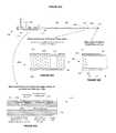
- FIG. 1illustrates a perspective view of an embodiment of a transseptal catheter in the right atrium consistent with the present disclosure
- FIG. 2illustrates a perspective view of an embodiment of a guide wire advanced into the superior vena cava consistent with the present disclosure
- FIG. 3illustrates a perspective view of an embodiment of a catheter advanced into the superior vena cava consistent with the present disclosure
- FIG. 4illustrates a perspective view of an embodiment of a catheter tip against the fossa ovalis consistent with the present disclosure
- FIG. 5illustrates a perspective view of an embodiment of a catheter tenting the fossa ovalis consistent with the present disclosure
- FIG. 6illustrates a perspective view of an embodiment of a needle puncturing the fossa ovalis consistent with the present disclosure
- FIG. 7illustrates a perspective view of an embodiment of a transseptal catheter punctured through the fossa ovalis consistent with the present disclosure
- FIG. 8illustrates a perspective view of an embodiment of a transseptal catheter in the left atrium with the needle removed consistent with the present disclosure
- FIG. 9illustrates a perspective view of an embodiment of a rail advanced into the right atrium through the transseptal catheter consistent with the present disclosure
- FIG. 10illustrates a perspective view of an embodiment of a sheath and dilator removed with a rail in the right atrium consistent with the present disclosure
- FIG. 11illustrates a perspective view of an embodiment of a dilator advanced to the left atrium consistent with the present disclosure
- FIG. 12illustrates a perspective view of one embodiment of a dilator consistent with the present disclosure
- FIG. 13Aillustrates a perspective view of an embodiment of a dilator consistent with the present disclosure
- FIG. 13Billustrates a close-up of one embodiment of the tip of the dilator shown in FIG. 13A consistent with the present disclosure
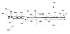
- FIG. 14Aillustrates a perspective view of a yet another embodiment of a dilator consistent with the present disclosure
- FIG. 14Billustrates a perspective view of one embodiment of the dilator shown in a deflected or retracted position consistent with the present disclosure
- FIG. 14Cillustrates a perspective view of one embodiment of the dilator shown in an inflated or expanded position consistent with the present disclosure
- FIG. 15illustrates a perspective view of a dilator in the inflated or expanded position located in the left atrium consistent with the present disclosure
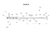
- FIG. 16illustrates a perspective view of a dilator in the inflated or expanded position located in the left atrium prior to passing through the mitral valve consistent with the present disclosure
- FIG. 17illustrates a perspective view of a dilator located in the left ventricle consistent with the present disclosure
- FIG. 18illustrates a perspective view of an embodiment of a steerable catheter advanced over the dilator in the left ventricle consistent with the present disclosure
- FIG. 19illustrates a perspective view of one embodiment of a steerable catheter consistent with the present disclosure
- FIGS. 20A-Dillustrate various views of another embodiment of a steerable catheter consistent with the present disclosure
- FIG. 21illustrates a perspective view of an embodiment of a steerable catheter in a non-deflected position consistent with the present disclosure
- FIG. 22illustrates a perspective view of an embodiment of a steerable catheter with the distal tip in a deflected position consistent with the present disclosure
- FIG. 23illustrates a perspective view of an embodiment of a steerable catheter with the proximal tip in a deflected position consistent with the present disclosure
- FIG. 24illustrates a perspective view of an embodiment of a steerable catheter with the distal tip and the proximal tip in a deflected position consistent with the present disclosure
- FIG. 25illustrates a perspective view of an embodiment of a steerable catheter advanced in the left ventricle with an implant loaded consistent with the present disclosure
- FIG. 26illustrates a perspective view of an embodiment of a steerable catheter being aimed or aligned with the implant site consistent with the present disclosure
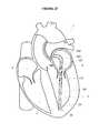
- FIG. 27illustrates a perspective view of an embodiment of a steerable catheter advanced to the implant site consistent with the present disclosure
- FIGS. 28-30illustrate one embodiment of a withdrawal sequence for a steerable catheter consistent with the present disclosure.
- the present disclosurerelates to a system and method of implanting a heart implant.
- the system and method according to one embodiment of the present disclosuremay be used to implant a heart valve implant which may suitably be used in connection with the treatment, diagnostics and/or correction of a dysfunctional or inoperative heart valve.
- a heart valve implantconsistent with the present disclosure is the treatment of mitral valve regurgitation.
- the heart valve implant hereinis described in terms of a mitral valve implant, such as may be used in treating mitral valve regurgitation as described in U.S. patent application Ser. No. 11/258,828 filed Oct. 26, 2005 and U.S. patent application Ser. No. 12/209,686 filed Sep.
- a heart valve implant consistent with the present disclosuremay be employed for treating, diagnosing and/or correcting other dysfunctional or inoperative heart valves.
- the present disclosureshould not, therefore, be construed as being limited to use as a mitral valve implant.
- the system and method according to the present disclosuremay be used to implant heart implants configured to be used in connection with the treatment, diagnostics and/or correction of other heart conditions.
- the system and method consistent with the present disclosuremay be used to implant a regurgitation implant configured to induce a controlled regurgitation in a heart valve (such as, but not limited to, a mitral heart valve), for example, in a manner that is generally consistent with advanced disease of the heart.
- the regurgitation implantmay include a regurgitation implant as described in U.S. patent Ser. No. 11/940,724 filed Nov. 15, 2007 and U.S. patent application Ser. No. 12/209,686 filed Sep. 12, 2008, both of which are fully incorporated herein by reference.
- a heart implant consistent with the present disclosuremay comprise a heart valve implant configured to interact with at least a portion of an existing heart valve to prevent and/or reduce regurgitation.
- a portion of one or more cusps of the heart valvemay interact with, engage, and/or seal against at least a portion of the heart valve implant when the heart valve is in a closed condition.
- the interaction, engagement and/or sealing between at least a portion of at least one cusp and at least a portion of the heart valve implantmay reduce and/or eliminate regurgitation in a heart valve, for example, providing insufficient sealing, including only a single cusp, e.g., following removal of a diseased and/or damaged cusp, and/or having a ruptured cordae.
- a heart valve implant consistent with the present disclosuremay be used in connection with various additional and/or alternative defects and/or deficiencies.
- the system and methodmay generally comprise placing a guide wire into the left ventricle and advancing a mitral valve implant through a delivery catheter and into the left ventricle.
- a guide wiremay be initially placed into the left atrium of the heart, for example, by way of transseptal puncture of the heart from the right atrium through the fossa ovalis into the left atrium.
- a dilatormay then be advanced along the guide wire to the left atrium and may be passed through the mitral valve into the left ventricle.
- the dilatormay include a balloon which may be inflated to facilitate passing the dilator through the mitral valve without damaging the mitral valve or becoming entangled in the mitral valve.
- a steerable cathetermay then be advanced along the dilator into the left ventrical.
- the steerable cathetermay be positioned within the left ventrical to the approximate location in which the implant will be secured.
- the implantmay then be advanced through the steerable catheter and secured to the native cardiac tissue.
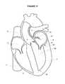
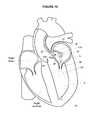
- FIG. 1a cross-sectional schematic view of a portion of a four chamber heart 1 is illustrated.
- the outflow tracts of the right and left ventricles 2 , 3are not shown in order to better illustrate the septum 4 between the right and left atria 5 , 6 .
- the inferior vena cava (IVC) 7 and superior vena cava (SVC) 8communicate with the right atrium 5 which is separated from the left atrium 6 by the intra-atrial septum 4 .
- IVCinferior vena cava
- SVCsuperior vena cava
- a guide wire 10may be advanced up the IVC 7 and into the right atrium 5 .
- the guide wire 10may include any guide wire configured to be advanced up the IVC 7 and into the right atrium 5 .
- the guide wire 10may be the same as the delivery guide wire discussed herein; however, the guide wire 10 may also be separate and distinct from the delivery guide wire.
- access to the right atrium 5may be accomplished by way of the Seldinger wire technique.
- the right femoral vein(not shown) may be accessed with a hollow needle (not shown) and a guide wire 10 may be inserted. The needle may be removed and a dilator 16 may be inserted over the guide wire 10 .
- the sheath 18 of a catheter 20(such as, but not limited to, a Mullins catheter or the like) having a pre-bent region 21 proximate the distal tip 23 of the catheter 20 may be inserted over the dilator 16 .
- the sheath 18 , dilator 16 , catheter 20 and guide wire 10may then be advanced up the IVC 7 through the opening 22 into the right atrium 5 as generally illustrated in FIG. 1 .
- the guide wire 10may be advanced out of the distal tip 23 of the dilator 16 , sheath 18 and/or catheter 20 as generally shown in FIG. 2 .
- the guide wire 10may be at least partially advanced into the SVC 8 as generally illustrated in FIG. 2 and the distal tip 23 of the catheter 20 may then be at least partially advanced along the guide wire 10 into the SVC 8 as generally illustrated in FIG. 3 .
- the SVC 8is a thin-walled vein, it may be advantageous to place the guide wire 10 in the SVC 8 and then advance the catheter 20 along the guide wire 10 since the spring-tipped atraumatic guide wire 10 reduces the potential for damaging the SVC 8 compared to the catheter 20 and dilator 16 .
- the guide wire 10may be retracted into the dilator 16 and the catheter 20 may be retracted (i.e., pulled downward) such that the pre-bent portion 21 of the sheath 18 facilitates guiding the distal tip 23 to the fossa ovalis 9 as generally illustrated in FIG. 4 .
- the sheath 18may be retracted proximally, dragging the distal tip 23 along the intra-atrial septum 4 until the distal tip 23 is positioned proximate to the fossa ovalis 9 .
- the position of the sheath 18 relative to the fossa ovalis 9may be confirmed by gently pushing the sheath 18 distally against the intra-atrial septum 4 to “tent” the fossa ovalis 9 as generally illustrated in FIG. 5 .
- the “tenting” of the fossa ovalis 9may be seen on ICE, fluoroscopy or the like.
- the guide wire 10may be removed from the catheter 20 and a transseptal needle 26 may be advanced through the catheter 20 towards the distal end 23 of the catheter 20 as generally shown in FIG. 6 .
- the position of the catheter 20may optionally be confirmed (for example, but not limited to, by “tenting”) and the transseptal needle 26 may be advanced out of the distal tip 23 to form a puncture 28 through the fossa ovalis 9 and into the left atrium 6 .
- the sheath 16 , dilator 28 and catheter 20may than be advanced through the puncture 28 of the fossa ovalis 9 and into the left atrium 6 as generally shown in FIG. 7 .
- the needle 26may be removed from the catheter 20 as generally shown in FIG. 8 .
- a delivery guide wire 30may be advanced through the catheter 20 until at least a portion of the distal tip 32 of the delivery guide wire 30 extends from the distal tip 23 of the catheter 20 and into the left atrium 6 as generally illustrated in FIG. 9 .
- the dilator 16 and the sheath 18may be removed, leaving just the delivery guide wire 30 in the left atrium 6 as generally illustrated in FIG. 10 .
- the delivery guide wire 30may be used as a guide for advancing other devices into the heart 1 , and ultimately, into the left ventricle 3 . Accordingly to at least one embodiment, the delivery guide wire 30 may be sufficiently stiff to resist undesirable bending and/or kinking and to resist undesirable movement of the distal tip 32 .
- the delivery guide wire 30may comprise a stiff, 0.018′′ diameter guide wire having a stiffness of approximately 19,900,000 psi. The stiffness of the delivery guide wire 30 was determined as follows.
- This stiffness of the delivery guide wire 30may therefore be approximately 19,900,000 psi.
- the delivery guide wire 30may have a stiffness greater than or less than 19,900,000 psi.
- the delivery guide wire 30may include a typical 0.018′′ guide wire (for example a 0.018′′ angled standard exchange guide wire made by Merit Medical Systems of South Jordan, Utah, Model H20STDA18260EX which was determined to have a stiffness of approximately 1,360,000 psi based on the same methodology). In either embodiment, the delivery guide wire 30 may have a diameter greater than or less than 0.018′′.
- a dilator 34may be advanced over the delivery guide wire 30 into the left atrium 6 .
- the dilator 34may be configured to pass through the mitral valve 61 into the left ventricle 3 without damaging the mitral valve 61 or becoming entangled in the mitral valve 61 (for example, the cusps 66 , the chordae and/or papillary muscles 68 of the mitral valve 61 ).
- the dilator 34 of the present disclosuremay be used to eliminate the rail as disclosed in U.S. patent application Ser. No. 12/209,686 filed Sep. 12, 2008.
- system and method disclosed in the present disclosure(and in particular the dilator 34 ) is not inconsistent with the system and method in U.S. patent application Ser. No. 12/209,686, and as such, the system and method disclosed in the present disclosure (including the dilator 34 ) may be used in conjunction with the system and method in U.S. patent application Ser. No. 12/209,686.
- the dilator 34 amay include define at least one lumen 94 configured to receive at least a portion of the delivery guide wire 30 .
- the lumen 94may have an internal diameter of approximately 0.038′′.
- the dilator 34 amay also comprise a shaft 96 including a tapered tip region 98 .
- the shaft 96may comprise a plurality of segments or portions having different stiffness or hardness to produce the desired overall curvature.
- the shaft 96may be formed from one or more suitable polymers such as, but not limited to, a polyether block amide.
- the shaft 96may have a constant inner and/or outer diameter and may be made from different materials to provide the various stiffness or hardness. Alternatively, or in addition, the shaft 96 may have different inner and/or outer diameters and may be made from one or more materials.
- the various stiffness or hardness of the shaft 96may be provided by varying the thickness of the shaft 96 at the different segments or portions. The different hardness of the segments may provide differing degrees of bending stiffness to the dilator 34 a which may facilitate advancing the dilator 34 a into and/or out of the left ventricle 3 .
- the dilator 34 amay comprise four different segments 97 a , 97 b , 97 c and 97 d .
- the first segment 97 amay be disposed proximate the distal end region 98 .
- the first segment 97 amay optionally include the tapered distal tip 98 and may have a length of approximately 6 inches.
- the tapered distal tip 98may be provided to facilitate advancing the tip 98 into the percutaneous puncture site in the groin as the dilator 34 a is introduced over the delivery guide wire 30 .
- the first segment 97 amay be formed of PEBAXTM 3533 having a durometer of 35 D.
- the second segment 97 bmay be adjacent to the first segment 97 a and may have a length of approximately 1.5 inches.
- the second segment 97 bmay be formed of PEBAXTM 2533 having a durometer of 25 D.
- the third segment 97 cmay be adjacent to the second segment 97 b and may have a length of approximately 2 inches.
- the third segment 97 cmay be formed of PEBAXTM 3533 having a durometer of 35 D.
- the forth segment 97 dmay be adjacent to the third segment 97 c and may have a length of approximately 42.5 inches.
- the forth segment 97 dmay be formed of PEBAXTM 7233 having a durometer of 72 D.
- the various lengths and hardness described above for the segments 97 a - 97 dmay be adjusted or changed depending upon the circumstances of its intended use. For example, patients with larger and/or smaller hearts may require one or more of the segments to be harder or softer.
- An important aspect of the segments 97 a - 97 dis that the softest segment is the second segment 97 b .
- the second segment 97 bis disposed approximately 6 inches from the tapered distal tip 98 .
- the location of the second segment 97 bmay generally correspond to the of the transseptal puncture site 13 where the curvature of the dilator 34 a may be greatest.
- the dilator 34may include a deflectable tip 98 a configured to allow the user to bend the distal region 109 of the dilator 34 b .
- the deflectable tip 98 amay facilitate advancement of the dilator 34 b through the mitral valve 61 may allowing the user to generally aim the tip 98 towards the mitral valve 61 .
- the dilator 34 bmay include a handle assembly 102 coupled to a proximal end 104 of the shaft 96 a .
- the shaft 96 amay include a plurality of segments, for example, the segments 97 a - 97 d described above.
- One or more deflecting wires 106may be coupled to the distal end region 109 of the shaft 96 a , for example, as generally illustrated in FIG. 13B .
- the defecting wire 106may optionally be disposed in a second lumen 113 disposed along the length of the shaft 96 a . Additional defecting wires 106 (not shown) may be provided in one or more additional lumens.
- the defecting wire 106may be coupled to the handle assembly 102 such that the distal tip 98 a may be bent as desired.
- the handle assembly 102may include at least one knob, slider or the like 115 coupled to the defecting wire 106 such that actuation of the knob 115 may result in movement of the distal tip 98 a .
- the knob 115may be coupled to the defecting wire 106 and may pull the defecting wire 106 generally towards the handle assembly 102 causing the distal tip 98 a to bend to one side.
- the handle assembly 102may also optionally include one or more valves or fittings.
- the handle assembly 102may include a fitting 111 (such as, but not limited to, a Luer lock fitting or the like) configured to allow the lumen 97 to be flushed.
- the handle assembly 102may also optionally include a valve 112 (such as, but not limited to, a hemostasis valve) configured to seal with the delivery guide wire 30 (not shown).
- the lumen 97may have various diameters along the length of the shaft 96 a .
- the lumen 97may have a smaller diameter proximate the distal tip 98 a compared to the remainder of the shaft 96 a .
- the lumen 97 proximate the tip 98 amay be slightly larger than the diameter of the delivery guide wire 30 (for example, but not limited to, slightly larger than 0.018′′) such that the dilator 34 a tracks well over the delivery guide wire 30 .
- the remainder of the lumen 97may have a larger diameter configured to reduce drag as the dilator 34 a is advanced over the delivery guide wire 30 .
- the dilator 34 cmay comprise an expandable device 114 (such as, but not limited to a balloon or the like) configured to facilitate advancement of the dilator 34 c through the mitral valve 61 without damaging the mitral valve 61 or becoming entangled in the mitral valve 61 (for example, the cusps 66 , the chordae and/or papillary muscles 68 of the mitral valve 61 ).
- the expanding portion 114may be disposed proximate the distal end region 109 of the shaft 96 b , for example, substantially adjacent to the tapered tip 98 a .
- the expanding portion 114may be fluidly coupled to an expanding medium such as, but not limited to, a gas and/or liquid which may expand and/or enlarge the expanding portion 114 from the deflated or retracted position as generally illustrated in FIG. 14B to the inflated or expanded position as generally illustrated in FIG. 14A .
- the expanding mediummay include carbon dioxide CO2 gas and/or saline.
- contrast mediamay be introduced into the expanding portion 114 to allow the expanding portion 114 to be more easily visually located using fluoroscopy or the like. The contrast media may coat the inside surface of the expanding portion 114 .
- the expanding mediummay be introduced through a fitting 111 .
- the expanding mediummay be coupled to the expanding portion 114 by way of the lumen 116 a as generally illustrated in FIG. 14C .
- the delivery guide wire 30may be received in the lumen 97 when the dilator 34 c is expanded.
- the expanding mediummay be coupled to the expanding portion 114 by way of a separate passageway (i.e., a passageway different from the lumen 97 configured to receive the delivery guide wire 30 ). This passageway may be the same lumen as the steering wire 106 is housed in, provided there is enough room for the expansion medium to pass around the steering wire.
- the expanding portion 114may include a resiliently expandable/collapsible material such as, but not limited to, silicone, YulexTM or the like which may be selectively collapsed and/or expanded.
- the expanding portion 114may be bonded to the shaft 96 b of the dilator 34 c and may include one or more passageways, aperture or lumen 116 fluidly coupled to the lumen 97 to allow the expansion medium to expand/collapse the expanding portion 114 .
- the diameter of the expanding portion 114should be small enough in the first or retracted/collapsed position to be advanced over the delivery guide wire 30 to the left atrium 6 and large enough when in the second or expanded/inflated position to be advanced through the cusps 66 and chordae 68 of the mitral valve 61 to reduce the potential of damaging the heart 1 and/or getting entangled within the mitral valve 61 .
- the shaft 97may have an outer diameter of approximately 0.062′′ (e.g., a 5 Fr) and a length of approximately 110 cm or greater.
- the expanding portion 114may diameter of approximately 0.100′′ in the first position and a diameter of approximately 15 mm to approximately 20 mm cm in the second position with a length of approximately 8 to approximately 10 mm.
- the dilator 34 cmay optionally include a deflectable tip 98 a configured to allow the user to bend the distal region 109 of the dilator 34 b as generally described herein.
- the dilator 34 cmay also optionally include one or more radiopaque markers 118 a - 118 n , for example, disposed about the distal end region 109 .
- the position markers 118 a - 118 nmay be spaced evenly along the shaft 97 (such as, but not limited to, approximately 2 cm intervals from the distal tip 98 a ) and may be used to verify the position of the dilator 34 c and/or for sizing the implant to be delivered.
- the dilator 34 consistent with the present disclosuremay have an overall length (i.e., from the distal tip 98 to the handle assembly 102 of approximately 145 cm or less. However, the length and/or the diameter of the dilator 34 may depend upon the introduction site as well as the intended patient's physiology.
- the dilator 34may be advanced over the delivery guide wire 30 proximate to the tip 32 of the delivery guide wire 30 .
- the tip 32may still extend beyond the tip 98 of the dilator 34 to protect the atrial wall from perforation.
- the expanding portion 114may be expanded as generally illustrated.
- the dilator 34may aimed generally towards the mitral valve 61 as generally illustrated in FIG. 16 .
- the tip 98may be bent or curved by actuating one or more knobs or the like (not shown) to move one or more deflecting wires as discussed herein.
- the tip 32 of the delivery guide wire 30may optionally be retracted into the lumen 97 of the dilator 34 to increase the flexibility of the distal tip region 109 .
- the curvature of the dilator 34may be confirmed using fluoroscopic and/or echo guidance techniques or the like.
- the contrast media and/or the radiopaque markersmay be used.
- the distal end region 109 of the dilator 34may be advanced through the mitral valve 61 .
- the dilator 34may be advanced through the mitral valve without either the deflectable tip 98 and/or the expandable portion 114 ; however, the use of one or more of the deflectable tip 98 and/or the expandable portion 114 may reduce the potential of damaging the heart 1 and/or getting entangled within the mitral valve 61 .
- the second segment 97 b of the shaft 96may generally correspond to the location of the bend or curve of the dilator 34 proximate the transseptal puncture site 13 .
- the necessary curvature of the dilator 34 between the transseptal puncture site 13 and the left ventricle 3is relatively sharp.
- the tip 32 of the delivery guide wire 30may be still located inside the lumen 97 of the dilator 34 back in the left atrium 6 generally where it was located in FIG. 16 .
- the dilator 34may not yet be aimed or directed at the intended implantation site at this point. Instead, it is only important that the distal end region 109 of the dilator 34 is through the mitral valve 61 without damaging and/or entangling the cusps 66 and the chordae/papillary muscles 68 .
- the expandable portion 114may be retracted/deflated and a steerable catheter 200 may be advanced over the dilator 34 into the left ventricle 3 proximate to the distal end region 109 of the dilator 34 .
- the steerable catheter 200may define at least one lumen 202 configured receive the dilator 34 as generally illustrated.
- the lumen 202may also be configured to receive an implant (not shown) such as, but not limited to, a mitral valve implant as generally disclosed in U.S. patent Ser. No. 11/940,724 filed Nov. 15, 2007 and U.S. patent application Ser. No. 12/209,686 filed Sep. 12, 2008, both of which are fully incorporated herein by reference.
- the steerable catheter 200may also be configured to be selectively curved or bent to facilitate aiming of the distal tip 204 for securing the implant and/or facilitate removal of the steerable catheter 200 .
- the steerable catheter 200 amay include shaft 206 defining at least one lumen 202 .
- the lumen 202may be configured to receive the dilator 34 and/or an implant (not shown).
- the shaft 206may also include a plurality of segments or portions 208 a - 208 n having different hardness or stiffness to produce the desired overall curvature.
- the shaft 206may be formed from one or more suitable polymers such as, but not limited to, a polyether block amide.
- the shaft 206may have a constant inner and/or outer diameter and may be made from different materials to provide the various stiffness or hardness.
- the shaft 206may have different inner and/or outer diameters and may be made from one or more materials.
- the various stiffness or hardness of the shaft 206may be provided by varying the thickness of the shaft 206 at the different segments or portions.
- the different hardness of the segmentsmay provide differing degrees of bending stiffness to the steerable catheter 200 a which may facilitate advancing the steerable catheter 200 a into and/or out of the left ventricle 3 as well as aiming or alignment of the steerable catheter 200 a.
- the steerable catheter 200 amay comprise three different segments 208 a , 208 b and 208 n .
- the first segment 208 amay be disposed proximate the distal tip 204 .
- the first segment 208 amay optionally include the tapered tip 209 and may have a length of approximately 8 inches.
- the tapered tip 209may be provided to facilitate advancing the steerable catheter 200 a into the percutaneous puncture site in the groin and over the dilator 34 .
- the first segment 208 amay be formed of PEBAXTM 2533 having a durometer of 25 D and may have a length of approximately 4 to 6 inches.
- the second segment 208 bmay be adjacent to the first segment 208 a and may have a length of approximately 2.5 inches.
- the second segment 208 bmay be formed of PEBAXTM 4033 having a durometer of 40 D.
- the third segment 208 nmay be adjacent to the second segment 208 b and may have a length sufficiently long to extend beyond the access incision.
- the third segment 208 nmay be formed of PEBAXTM 7233 having a durometer of 72 D.
- the various lengths and hardness described above for the segments 208 a - 208 nmay be adjusted or changed depending upon the circumstances of its intended use. For example, patients with larger and/or smaller hearts may require one or more of the segments to be longer or short.
- An important aspect of the segments 208 a - 208 nis that the softest segment is the first segment 208 a . Also, the second segment 208 b is disposed approximately 4 to 6 inches from the distal tip 209 .
- the length of the first segment 208 amay generally correspond to the length between the transseptal puncture site 13 and the implantation site (e.g., the apex) in the left ventricle 3 where the curvature of the steerable catheter 200 a may be greatest.
- the steerable catheter 200 amay also include a first steering device 210 .
- the first steering device 210may include a pull ring or the like which may be disposed about 1.5-4 inches from the distal end of the tip 209 .
- the exact length of the first steering device 210 from the tip 209may depend on the size of the patient's heart which may vary quite a bit depending on, among other things, the degree of regurgitation. For example, patients with functional mitral regurgitation often have dilated cardiomyopathy (enlarged left ventricle).
- the first steering device 210may be located 2 inches from the tip 209 .
- the steerable catheter 200 amay optionally include at least a second steering device 212 .
- the second steering device 212may include a pull ring or the like which may be disposed proximate to the distal end of the tip 209 .
- the second or more steering devices 212may be provided to facilitate curving or bending of the steerable catheter 200 a .
- the first and second steerable devices 210 , 212may be configured to reduce drag during withdrawal and may also facilitate alignment or aiming of the tip 209 within the left ventricle 3 .
- the first and second steerable devices 210 , 212may also facilitate advancement of the steerable catheter 200 a over the dilator 34 , through the transseptal puncture site 13 , and through the left atrium 6 and down into the left ventricle 3 .
- the first and/or second steerable devices 210 , 212may be coupled to a handle assembly 214 which may be disposed about a proximal end 216 of the shaft 206 .
- the handle assembly 214may include one or more fittings and/or valves.
- the handle assembly 214may include a valve 215 (for example, but not limited to, a hemostasis valve or the like) and/or a fitting 217 (for example, but not limited to, a luer lock fitting or the like).
- the handle assembly 214may also include one or more actuation devices 218 a - 218 n (such as, but not limited to, knobs, sliders, or the like) coupled to the first and second steerable devices 210 , 212 .
- the actuation devices 218 a - nmay be configured to place the first and second steerable devices 210 , 212 under tension, therefore causing the shaft 206 to deflect (e.g., curve or bend).
- the steerable catheter 200 bmay include actuation devices 218 a - n coupled to the first and/or second steerable devices 210 , 212 by way of one or more wires or the like 220 disposed along at least a portion of the shaft 206 as generally illustrated in FIGS. 20A-20D .
- the actuation devices 218 a - nmay be slide distally and/or proximally within the handle assembly 214 to increase or decrease the tension placed on the wires 220 .
- the tension in the wires 220may asymmetrically urge/pull the first and/or second steerable devices 210 , 212 (e.g., the first and/or second pull rings) to one side causing the shaft 206 to defect or curve where the wires 220 are coupled to the first and/or second steerable devices 210 , 212 .
- the shaft 206may optionally include an inner layer 230 configured to provide a substantially seamless inner surface of the lumen 202 .
- the inner layer 230may also be configured to reduce and/or minimize surface friction.
- the inner layer 230may include PTFE or the like.
- the shaft 206may also include another layer 232 configured to provide the desired stiffness.
- the layer 232may include PebaxTM or the like.
- the shaft 206may include three or more sections configured to provide kink resistance, pushability, and/or flexibility.
- the shaft 206may include a reinforced section 234 disposed between the first steering device 210 and the second steering device 212 .
- the reinforced section 234may be configured to provide increased flexibility, which may facilitate navigating the shaft 206 to the left ventricle 3 and configured to provide increased kink resistance.
- the reinforced section 234may be spiral reinforced and may have a length of 1-3 inches.
- the shaft 206may also optionally include spiral reinforced section 236 (as generally illustrated in FIGS. 19 and 20C ).
- the spiral reinforced section 236may extend from the first steering device 210 towards the handle assembly 214 for about 7.5 inches.
- the spiral reinforced section 236may be configured to provide kink resistance when deflecting the shaft 206 using the first and/or second steerable devices 210 , 212 .
- a kink in the shaft 206may reduce the ability of the user to locate the distal tip 209 within the left ventricle 3 and may also increase the force needed to push the implant through the lumen 202 during deployment.
- the shaft 206may also optionally include a braided reinforced section 238 .
- the braided reinforced section 238may extend from the proximal end of the spiral reinforced section 236 to the handle assembly 214 .
- the braided reinforced section 238may be configured to increase the pushability and torsional strength of the shaft 206 while reducing and/or minimizing kinking. Increasing the pushability and torsional strength and preventing kinking may be important since the length of the shaft 206 from the groin (where the steerable catheter 204 may be introduced) to the left ventricle 3 may be fairly long and involve tortuous anatomy.
- FIGS. 21-24the effects of actuating the first and/or second steerable devices 210 , 212 on the shaft 206 are generally illustrated.
- FIG. 21generally illustrates one embodiment of a steerable catheter 202 a in which the shaft 206 is unbiased.
- FIG. 22generally illustrates deflection of the distal region 240 .
- a usermay actuate the second actuation device 218 n (for example, but not limited to, by sliding the second actuation device 218 n generally in the direction of arrow A) causing the second steerable device 212 to deflect the shaft 206 in a region 240 proximate the second steerable device 212 .
- the second steerable device 212may cause the shaft 206 to deflect and/or bend in a region 240 between the second steerable device 212 and the handle assembly 214 .
- the second steerable device 212may generally cause the shaft 206 to deflect and/or bend in a region 240 between the second steerable device 212 and the first steerable device 210 .
- the second steerable device 212may generally cause the shaft 206 to deflect and/or bend up to approximately 180 degrees, though angles of curvature greater than 180 degrees are also possible depending on flexibility of the shaft 206 as well as the effects of the shaft 206 needing to bend passively to accommodate the patient's anatomy.
- the radius of the curvaturemay be 1.0 inches to 2.0 inches, for example, 1.25 inches to 1.75 inches.
- FIG. 23generally illustrates deflection of the proximal region 242 .
- a usermay actuate the first actuation device 218 a (for example, but not limited to, by sliding the first actuation device 218 a generally in the direction of arrow B) causing the first steerable device 210 to deflect the shaft 206 in a region 242 proximate the first steerable device 210 .
- the first steerable device 210may cause the shaft 206 to deflect and/or bend in a region 242 between the first steerable device 210 and the handle assembly 214 .
- the first steerable device 210may generally cause the shaft 206 to deflect and/or bend up to approximately 180 degrees, though angles of curvature greater than 180 degrees are also possible depending on flexibility of the shaft 206 as well as the effects of the shaft 206 needing to bend passively to accommodate the patient's anatomy.
- the radius of the curvaturemay be 1.0 inches to 2.0 inches, for example, 1.25 inches to 1.75 inches.
- the first and second steerable devices 210 , 212may generally cause the shaft 206 to deflect and/or bend up to approximately 180 degrees, though angles of curvature greater than 180 degrees are also possible depending on flexibility of the shaft 206 as well as the effects of the shaft 206 needing to bend passively to accommodate the patient's anatomy.
- the radius of the curvaturemay be 1.0 inches to 2.0 inches, for example, 1.25 inches to 1.75 inches, however, the exact range of the radius may depend upon the location of the first and second steerable devices 210 , 212 as well as the flexibility of the regions 240 , 242 .
- the dilator 34has been removed from the steerable catheter 200 and the implant (not shown) may be advanced through the lumen 202 proximate to the distal end 219 .
- the usermay aim and/or align the distal end segment and/or distal tip 219 of the steerable catheter 200 to the desired location within the left ventricle 3 where it is desired to anchor or secure the implant by deflecting the shaft 206 in the region 242 as generally illustrated by the arrows in FIG. 26 representing the deflection of the steerable catheter 200 .
- Fluoroscopic and/or echo guidancemay be used to facilitate aiming of the steerable catheter 200 within the left ventricle 3 .
- the location of the first steerable actuator 210 and the region 242 along the shaft 206may generally correspond to the position of the shaft 206 within the left atrium 6 and/or the left ventricle 3 proximate to the mitral valve 61 .
- the proximal ring 210would reside somewhere between the annulus of the valve and the valve leaflets. This would provide for the distal section 234 to be pointed relatively straight at the desired anchor location.
- the differing lengths of the first section 234may compensate for the variations in the patients' valve to apex length, although anchoring directly in the apex may not always be the desired location. In FIG. 26 the illustrated bend in the catheter may be closer to the valve.
- the implant 110may be anchored and/or secured to the native tissue.
- the implant 110may include a shaft 120 coupled to a spacer 122 and an anchoring device 124 as generally illustrated in FIG. 27 and described in U.S. patent Ser. No. 11/940,724 filed Nov. 15, 2007 and U.S. patent application Ser. No. 12/209,686 filed Sep. 12, 2008, both of which are fully incorporated herein by reference.
- the implant 110may include any other device configured to be received within the lumen 202 of the delivery catheter and/or delivered to the heart 1 .
- the implant 110may optionally be advanced through the lumen 202 of steerable catheter 200 using a pusher 280 or the like. Securing the implant 110 to the tissue may depend upon the specifics of the design of the implant 110 .
- the implant 110may be secured to the tissue using one or more screws (for example, but not limited to, helical screws or the like), tines, and/or sutures (such as, but not limited to, one or more sutures formed, at least in part, of a shape memory alloy).
- the steerable catheter 200may be removed from the left ventricle 3 and ultimately from the heart 1 and the patient's body. According to one embodiment, the steerable catheter 200 may be removed by urging the steerable catheter 200 proximally (i.e., away from the left ventricle 3 ).
- the first steering actuator 210may be used to minimize the force applied against the implant 110 by the steerable catheter 200 as the implant 110 exits the lumen 202 of the steerable catheter 200 . If the force applied to the implant 110 by the steerable catheter 200 as the implant 110 exits the lumen 202 of the steerable catheter 200 is too great, damage may occur to the heart 1 proximate to the implant site and/or the implant 110 may be accidentally pulled out and/or disconnected from the tissue.
- the force applied to the implant 110 by the steerable catheter 200 as the implant 110 exits the lumen 202 of the steerable catheter 200may be further reduced with the aid of the second or more steerable actuators 212 .
- FIGS. 28-30one embodiment generally illustrating the deflection withdrawal sequence of a steerable catheter 200 having at least a first and a second steerable actuator 210 , 212 is shown.
- FIG. 28generally illustrates one embodiment of the steerable catheter 200 .
- the implant 110(not shown) has been secured to the tissue.
- the second steerable actuator 212is illustrated in the “straight” position (i.e., the second steerable actuator 212 is not urging the shaft 206 of the steerable catheter 200 ).
- the region 240 between the second steerable actuator 212 and the first steerable actuator 210(for example, but not limited, the distal most 3 inches of the shaft 206 ) is over the implant 110 from the apex 36 of the left ventricle 3 up to the mitral valve 61 .
- the first steerable actuator 210is in the bent or curved position to deflect the shaft 206 in order to accommodate the curve or bend from the mitral valve 60 , through the transseptal puncture site 13 , and into the right atrium 5 .
- the region 240 of the steerable catheter 200may start to encounter the curvature in the left atrium 6 between the mitral valve 61 and the transseptal puncture site 13 .
- the second actuation device 212may be actuated to deflect the region 240 of the shaft 206 of the steerable catheter 200 as generally illustrated in FIG. 29 . Deflecting the region 240 of the shaft 206 may reduce drag of the steerable catheter 200 on the implant 110 and may also reduce the likelihood of dislodging the implant 110 from the tissue.
- the usermay also un-bend the region 242 of the shaft 206 as the region 242 is moving through the transseptal puncture site 13 and into a region of reduced curvature.
- the second actuation device 212may be un-bent to un-bend the region 240 of the shaft 206 as it moves through the transseptal puncture site 13 as generally illustrated in FIG. 30 .
- both regions 240 , 242 of the shaft 206may be somewhat curved passively by the anatomy alone.
- the present disclosuremay include a steerable catheter including a first steerable actuator disposed 1.5-4 inches from the distal tip of the shaft.
- the first steerable actuatormay include, but is not limited to, a pull ring or the like.
- the steerable catheter having a first steerable actuatormay facilitate aiming or positioning the tip of the steerable catheter to the desired location within the left ventricle.
- the first steerable actuatormay also reduce the force exerted on the implant by the shaft when removing steerable catheter from the left ventricle and may also reduce damage to the heart by allowing the shaft to better conform to the geometries of the pathway.
- the steerable cathetermay optionally include at least a second steerable actuator in addition to the first steerable actuator.
- the second steerable actuatormay include, but is not limited to, a pull ring or the like which may be positioned proximate to the distal tip of the shaft.
- the second steerable actuatormay further reduce the force exerted on the implant by the shaft when removing steerable catheter from the left ventricle and may also reduce damage to the heart by allowing the shaft to better conform to the geometries of the pathway.
- the first and/or second steerable actuatorsmay also facilitate advancing the steerable catheter over a dilator through the tortuous pathway of the transseptal route to the left ventricle.
- the present disclosuremay also include a dilator having a plurality of segments having different hardness or stiffness.
- the different segmentsmay improve the ability of the steerable catheter to be inserted over the dilator through the tortuous pathway of the transseptal route to the left ventricle.
- the dilatormay include four segments wherein the softest segment is located approximately 6 inches from the distal tip.
- the dilatormay optionally include an expandable device (such as, but not limited to, a balloon or the like) disposed proximate the distal tip.
- the expandable devicemay facilitate advancing the dilator through the mitral valve without damaging the mitral valve (for example, damaging and/or becoming entangled in the cusps and/or papillary muscles).
- the dilatormay also optionally include a deflectable tip.
- the deflectable tipmay improve the general control of the dilator as it is advanced over a guide wire the transseptal route to the left atrium.
- the deflectable tipmay also allow the expandable device to be aimed towards the mitral valve, further facilitating the advancement to the dilator through the mitral valve.
- An implant consistent with the present disclosuremay also comprise other embodiments, for example, but not limited to, one or more of the implants as described in U.S. patent application Ser. Nos. 11/258,828 filed Oct. 26, 2005 and entitled HEART VALVE IMPLANT; 11/940,724 filed on Nov. 15, 2007 and entitled HEART REGURGITATION METHOD AND APPARATUS; 11/748,121 filed on May 14, 2007 and entitled BALLOON MITRAL SPACER; 11/748,138 filed on May 14, 2007 and entitled SOLID CONSTRUCT MITRAL SPACER; 11/940,674 filed on Nov.
- the steerable catheter and/or dilator disclosed hereinmay be used to deliver an implant.
- a heart valve implant consistent with the present disclosuremay be used in the treatment mitral valve regurgitation.
- the heart valve implant as well as its associated methodsmay also suitably be employed in other applications, e.g., as an implant associated with one of the other valves of the heart, etc.
- the present disclosureshould not, therefore, be construed as being limited to use for reducing and/or preventing regurgitation of the mitral valve.
- the present disclosureis not intended to be limited to an apparatus, system or method which must satisfy one or more of any stated or implied object or feature of the present disclosure and should not be limited to the preferred, exemplary, or primary embodiment(s) described herein.
- the foregoing description of the present disclosurehas been presented for purposes of illustration and description. It is not intended to be exhaustive or to limit the invention to the precise form disclosed. Obvious modifications or variations are possible in light of the above teachings. The embodiments were chosen and described to provide the best illustration of the principles of the present disclosure and its practical application to thereby enable one of ordinary skill in the art to utilize the present disclosure in various embodiments and with various modifications as is suited to the particular use contemplated. All such modifications and variations are within the scope of the present disclosure when interpreted in accordance with breadth to which it is fairly, legally and equitably entitled.
Landscapes
- Health & Medical Sciences (AREA)
- Life Sciences & Earth Sciences (AREA)
- Engineering & Computer Science (AREA)
- Animal Behavior & Ethology (AREA)
- Veterinary Medicine (AREA)
- Public Health (AREA)
- Biomedical Technology (AREA)
- Heart & Thoracic Surgery (AREA)
- General Health & Medical Sciences (AREA)
- Anesthesiology (AREA)
- Hematology (AREA)
- Pulmonology (AREA)
- Biophysics (AREA)
- Cardiology (AREA)
- Mechanical Engineering (AREA)
- Oral & Maxillofacial Surgery (AREA)
- Transplantation (AREA)
- Vascular Medicine (AREA)
- Prostheses (AREA)
- Surgical Instruments (AREA)
Abstract
Description
- Where:
- n=a constant that is equal to 4 if both ends of the column are clamped and cannot move or rotate.
- E=Modulus of elasticity of the material (psi)
- I=Moment of inertia (in4)
For a circular cross-section the moment of inertia is:
Substituting for I in the first equation for Pcrleads to:
And solving for the modulus leads to:
This stiffness of the
Claims (22)
Priority Applications (4)
| Application Number | Priority Date | Filing Date | Title |
|---|---|---|---|
| US12/510,929US8591460B2 (en) | 2008-06-13 | 2009-07-28 | Steerable catheter and dilator and system and method for implanting a heart implant |
| EP10804952.9AEP2459266B1 (en) | 2009-07-28 | 2010-07-27 | Steerable catheter and dilator and system for implanting a heart implant |
| PCT/US2010/043360WO2011014496A1 (en) | 2009-07-28 | 2010-07-27 | Steerable catheter and dilator and system and method for implanting a heart implant |
| US14/090,418US20140276395A1 (en) | 2008-06-13 | 2013-11-26 | Steerable Catheter and Dilator and System and Method for Implanting a Heart Implant |
Applications Claiming Priority (3)
| Application Number | Priority Date | Filing Date | Title |
|---|---|---|---|
| US6134308P | 2008-06-13 | 2008-06-13 | |
| US12/209,686US9259317B2 (en) | 2008-06-13 | 2008-09-12 | System and method for implanting a heart implant |
| US12/510,929US8591460B2 (en) | 2008-06-13 | 2009-07-28 | Steerable catheter and dilator and system and method for implanting a heart implant |
Related Parent Applications (1)
| Application Number | Title | Priority Date | Filing Date |
|---|---|---|---|
| US12/209,686Continuation-In-PartUS9259317B2 (en) | 2005-10-26 | 2008-09-12 | System and method for implanting a heart implant |
Related Child Applications (1)
| Application Number | Title | Priority Date | Filing Date |
|---|---|---|---|
| US14/090,418ContinuationUS20140276395A1 (en) | 2008-06-13 | 2013-11-26 | Steerable Catheter and Dilator and System and Method for Implanting a Heart Implant |
Publications (2)
| Publication Number | Publication Date |
|---|---|
| US20100022948A1 US20100022948A1 (en) | 2010-01-28 |
| US8591460B2true US8591460B2 (en) | 2013-11-26 |
Family
ID=43529668
Family Applications (2)
| Application Number | Title | Priority Date | Filing Date |
|---|---|---|---|
| US12/510,929Active2031-03-25US8591460B2 (en) | 2008-06-13 | 2009-07-28 | Steerable catheter and dilator and system and method for implanting a heart implant |
| US14/090,418AbandonedUS20140276395A1 (en) | 2008-06-13 | 2013-11-26 | Steerable Catheter and Dilator and System and Method for Implanting a Heart Implant |
Family Applications After (1)
| Application Number | Title | Priority Date | Filing Date |
|---|---|---|---|
| US14/090,418AbandonedUS20140276395A1 (en) | 2008-06-13 | 2013-11-26 | Steerable Catheter and Dilator and System and Method for Implanting a Heart Implant |
Country Status (3)
| Country | Link |
|---|---|
| US (2) | US8591460B2 (en) |
| EP (1) | EP2459266B1 (en) |
| WO (1) | WO2011014496A1 (en) |
Cited By (50)
| Publication number | Priority date | Publication date | Assignee | Title |
|---|---|---|---|---|
| US9693865B2 (en) | 2013-01-09 | 2017-07-04 | 4 Tech Inc. | Soft tissue depth-finding tool |
| US20170266003A1 (en)* | 2014-07-30 | 2017-09-21 | Mitraltech Ltd. | Articulatable prosthetic valve |
| US9801720B2 (en) | 2014-06-19 | 2017-10-31 | 4Tech Inc. | Cardiac tissue cinching |
| US9907681B2 (en) | 2013-03-14 | 2018-03-06 | 4Tech Inc. | Stent with tether interface |
| US9907547B2 (en) | 2014-12-02 | 2018-03-06 | 4Tech Inc. | Off-center tissue anchors |
| US9974651B2 (en) | 2015-02-05 | 2018-05-22 | Mitral Tech Ltd. | Prosthetic valve with axially-sliding frames |
| US9987132B1 (en) | 2016-08-10 | 2018-06-05 | Mitraltech Ltd. | Prosthetic valve with leaflet connectors |
| US10022114B2 (en) | 2013-10-30 | 2018-07-17 | 4Tech Inc. | Percutaneous tether locking |
| US10052095B2 (en) | 2013-10-30 | 2018-08-21 | 4Tech Inc. | Multiple anchoring-point tension system |
| US10058323B2 (en) | 2010-01-22 | 2018-08-28 | 4 Tech Inc. | Tricuspid valve repair using tension |
| US10154903B2 (en) | 2016-08-01 | 2018-12-18 | Cardiovalve Ltd. | Minimally-invasive delivery systems |
| USD841813S1 (en) | 2017-08-03 | 2019-02-26 | Cardiovalve Ltd. | Prosthetic heart valve element |
| US10226341B2 (en) | 2011-08-05 | 2019-03-12 | Cardiovalve Ltd. | Implant for heart valve |
| US10238491B2 (en) | 2010-01-22 | 2019-03-26 | 4Tech Inc. | Tricuspid valve repair using tension |
| US10245143B2 (en) | 2011-08-05 | 2019-04-02 | Cardiovalve Ltd. | Techniques for percutaneous mitral valve replacement and sealing |
| US10368988B2 (en) | 2016-11-09 | 2019-08-06 | Medtronic Vascular, Inc. | Valve delivery system having an integral displacement component for managing chordae tendineae in situ and methods of use thereof |
| US10390952B2 (en) | 2015-02-05 | 2019-08-27 | Cardiovalve Ltd. | Prosthetic valve with flexible tissue anchor portions |
| US10405978B2 (en) | 2010-01-22 | 2019-09-10 | 4Tech Inc. | Tricuspid valve repair using tension |
| US10493248B2 (en) | 2016-11-09 | 2019-12-03 | Medtronic Vascular, Inc. | Chordae tendineae management devices for use with a valve prosthesis delivery system and methods of use thereof |
| US10512456B2 (en) | 2010-07-21 | 2019-12-24 | Cardiovalve Ltd. | Techniques for percutaneous mitral valve replacement and sealing |
| US10531866B2 (en) | 2016-02-16 | 2020-01-14 | Cardiovalve Ltd. | Techniques for providing a replacement valve and transseptal communication |
| US10575948B2 (en) | 2017-08-03 | 2020-03-03 | Cardiovalve Ltd. | Prosthetic heart valve |
| US10631982B2 (en) | 2013-01-24 | 2020-04-28 | Cardiovale Ltd. | Prosthetic valve and upstream support therefor |
| US10716668B2 (en) | 2017-04-05 | 2020-07-21 | Medtronic, Inc. | Delivery system with anchoring nosecone and method of delivery |
| US10806574B2 (en) | 2017-11-20 | 2020-10-20 | Medtronic Vascular, Inc. | Delivery systems having a temporary valve and methods of use |
| US10888421B2 (en) | 2017-09-19 | 2021-01-12 | Cardiovalve Ltd. | Prosthetic heart valve with pouch |
| US10925728B2 (en) | 2018-02-22 | 2021-02-23 | Medtronic Vascular, Inc. | Prosthetic heart valve delivery systems and methods |
| US11026791B2 (en) | 2018-03-20 | 2021-06-08 | Medtronic Vascular, Inc. | Flexible canopy valve repair systems and methods of use |
| US20210220131A1 (en)* | 2019-02-27 | 2021-07-22 | Synecor Llc | Transseptal delivery system and methods for therapeutic devices of the aortic valve |
| US11071846B2 (en) | 2017-09-14 | 2021-07-27 | Medtronic Vascular, Inc. | Deflection catheter for aiding in bending of a catheter |
| US11109964B2 (en) | 2010-03-10 | 2021-09-07 | Cardiovalve Ltd. | Axially-shortening prosthetic valve |
| US11135060B2 (en) | 2017-08-24 | 2021-10-05 | Medtronic Vascular, Inc. | Transseptal delivery systems having a deflecting segment and methods of use |
| US11141268B2 (en) | 2009-12-08 | 2021-10-12 | Cardiovalve Ltd. | Prosthetic heart valve with upper and lower skirts |
| US11246704B2 (en) | 2017-08-03 | 2022-02-15 | Cardiovalve Ltd. | Prosthetic heart valve |
| US11285003B2 (en) | 2018-03-20 | 2022-03-29 | Medtronic Vascular, Inc. | Prolapse prevention device and methods of use thereof |
| US11291547B2 (en) | 2011-08-05 | 2022-04-05 | Cardiovalve Ltd. | Leaflet clip with collars |
| US11344410B2 (en) | 2011-08-05 | 2022-05-31 | Cardiovalve Ltd. | Implant for heart valve |
| US11382746B2 (en) | 2017-12-13 | 2022-07-12 | Cardiovalve Ltd. | Prosthetic valve and delivery tool therefor |
| US11612482B2 (en) | 2019-03-06 | 2023-03-28 | Medtronic, Inc. | Trans-septal delivery system and methods of use |
| US11633277B2 (en) | 2018-01-10 | 2023-04-25 | Cardiovalve Ltd. | Temperature-control during crimping of an implant |
| US11653910B2 (en) | 2010-07-21 | 2023-05-23 | Cardiovalve Ltd. | Helical anchor implantation |
| US11684474B2 (en) | 2018-01-25 | 2023-06-27 | Edwards Lifesciences Corporation | Delivery system for aided replacement valve recapture and repositioning post-deployment |
| US11793633B2 (en) | 2017-08-03 | 2023-10-24 | Cardiovalve Ltd. | Prosthetic heart valve |
| US11832829B2 (en) | 2017-04-20 | 2023-12-05 | Medtronic, Inc. | Stabilization of a transseptal delivery device |
| US11925554B1 (en) | 2022-10-07 | 2024-03-12 | Vantis Vascular, Inc. | Method and apparatus for antegrade transcatheter valve repair or implantation |
| US11964091B1 (en)* | 2023-10-10 | 2024-04-23 | Vantis Vascular, Inc. | Method and apparatus for catheter-based extracorporeal membrane oxygenation (ECMO) |
| US12029646B2 (en) | 2017-08-03 | 2024-07-09 | Cardiovalve Ltd. | Prosthetic heart valve |
| US12226564B1 (en) | 2023-10-10 | 2025-02-18 | Vantis Vascular, Inc. | Method and apparatus for catheter-based extracorporeal membrane oxygenation (ECMO) |
| US20250186669A1 (en)* | 2023-10-10 | 2025-06-12 | Vantis Vascular, Inc. | Method and apparatus for catheter-based extracorporeal membrane oxygenation (ecmo) |
| US12357459B2 (en) | 2020-12-03 | 2025-07-15 | Cardiovalve Ltd. | Transluminal delivery system |
Families Citing this family (112)
| Publication number | Priority date | Publication date | Assignee | Title |
|---|---|---|---|---|
| US7780723B2 (en) | 2005-06-13 | 2010-08-24 | Edwards Lifesciences Corporation | Heart valve delivery system |
| US9259317B2 (en) | 2008-06-13 | 2016-02-16 | Cardiosolutions, Inc. | System and method for implanting a heart implant |
| US8778017B2 (en) | 2005-10-26 | 2014-07-15 | Cardiosolutions, Inc. | Safety for mitral valve implant |
| US8852270B2 (en) | 2007-11-15 | 2014-10-07 | Cardiosolutions, Inc. | Implant delivery system and method |
| US8216302B2 (en) | 2005-10-26 | 2012-07-10 | Cardiosolutions, Inc. | Implant delivery and deployment system and method |
| US8092525B2 (en)* | 2005-10-26 | 2012-01-10 | Cardiosolutions, Inc. | Heart valve implant |
| US7785366B2 (en) | 2005-10-26 | 2010-08-31 | Maurer Christopher W | Mitral spacer |
| US8449606B2 (en) | 2005-10-26 | 2013-05-28 | Cardiosolutions, Inc. | Balloon mitral spacer |
| US8932348B2 (en) | 2006-05-18 | 2015-01-13 | Edwards Lifesciences Corporation | Device and method for improving heart valve function |
| AU2007266448B2 (en) | 2006-06-01 | 2013-07-18 | Edwards Lifesciences Corporation | Prosthetic insert for improving heart valve function |
| US8480730B2 (en) | 2007-05-14 | 2013-07-09 | Cardiosolutions, Inc. | Solid construct mitral spacer |
| US8597347B2 (en) | 2007-11-15 | 2013-12-03 | Cardiosolutions, Inc. | Heart regurgitation method and apparatus |
| US8808345B2 (en) | 2008-12-31 | 2014-08-19 | Medtronic Ardian Luxembourg S.A.R.L. | Handle assemblies for intravascular treatment devices and associated systems and methods |
| US10856978B2 (en) | 2010-05-20 | 2020-12-08 | Jenavalve Technology, Inc. | Catheter system |
| US9248262B2 (en) | 2010-08-31 | 2016-02-02 | Vibha Agarwal | Vascular dilator for controlling blood flow in a blood vessel |
| CA2822381C (en) | 2010-12-23 | 2019-04-02 | Foundry Newco Xii, Inc. | System for mitral valve repair and replacement |
| US8430864B2 (en)* | 2011-02-16 | 2013-04-30 | Biosense Webster, Inc. | Catheter with multiple deflections |
| JP5872692B2 (en) | 2011-06-21 | 2016-03-01 | トゥエルヴ, インコーポレイテッド | Artificial therapy device |
| EP4101399B1 (en) | 2011-08-05 | 2025-04-09 | Route 92 Medical, Inc. | System for treatment of acute ischemic stroke |
| US10779855B2 (en) | 2011-08-05 | 2020-09-22 | Route 92 Medical, Inc. | Methods and systems for treatment of acute ischemic stroke |
| US11202704B2 (en) | 2011-10-19 | 2021-12-21 | Twelve, Inc. | Prosthetic heart valve devices, prosthetic mitral valves and associated systems and methods |
| US9655722B2 (en) | 2011-10-19 | 2017-05-23 | Twelve, Inc. | Prosthetic heart valve devices, prosthetic mitral valves and associated systems and methods |
| JP6133309B2 (en) | 2011-10-19 | 2017-05-24 | トゥエルヴ, インコーポレイテッド | Prosthetic heart valve device |
| EA201400478A1 (en) | 2011-10-19 | 2014-10-30 | Твелв, Инк. | DEVICES, SYSTEMS AND METHODS OF PROTESIZING THE HEART VALVE |
| US9763780B2 (en) | 2011-10-19 | 2017-09-19 | Twelve, Inc. | Devices, systems and methods for heart valve replacement |
| US9039757B2 (en) | 2011-10-19 | 2015-05-26 | Twelve, Inc. | Prosthetic heart valve devices, prosthetic mitral valves and associated systems and methods |
| US8945025B2 (en) | 2011-12-30 | 2015-02-03 | St. Jude Medical, Atrial Fibrillation Division, Inc. | Catheter with atraumatic tip |
| EP2816966B1 (en)* | 2012-02-22 | 2023-10-25 | Veran Medical Technologies, Inc. | Steerable surgical catheter comprising a biopsy device at the distal end portion thereof |
| US9579198B2 (en) | 2012-03-01 | 2017-02-28 | Twelve, Inc. | Hydraulic delivery systems for prosthetic heart valve devices and associated methods |
| US9474605B2 (en) | 2012-05-16 | 2016-10-25 | Edwards Lifesciences Corporation | Devices and methods for reducing cardiac valve regurgitation |
| US8961594B2 (en) | 2012-05-31 | 2015-02-24 | 4Tech Inc. | Heart valve repair system |
| US10179009B2 (en) | 2012-08-07 | 2019-01-15 | Ahmad Abdul-Karim | Needleless transseptal access device and methods |
| US9232998B2 (en) | 2013-03-15 | 2016-01-12 | Cardiosolutions Inc. | Trans-apical implant systems, implants and methods |
| US9289297B2 (en) | 2013-03-15 | 2016-03-22 | Cardiosolutions, Inc. | Mitral valve spacer and system and method for implanting the same |
| US12426922B2 (en) | 2013-04-15 | 2025-09-30 | Transseptal Solutions Ltd. | Fossa ovalis penetration catheter |
| US9545265B2 (en) | 2013-04-15 | 2017-01-17 | Transseptal Solutions Ltd. | Fossa ovalis penetration using balloons |
| US9700351B2 (en) | 2013-04-15 | 2017-07-11 | Transseptal Solutions Ltd. | Fossa ovalis penetration |
| US9788858B2 (en) | 2013-04-15 | 2017-10-17 | Transseptal Solutions Ltd. | Fossa ovalis penetration using probing elements |
| AU2014268631B2 (en) | 2013-05-20 | 2019-08-01 | Twelve, Inc. | Implantable heart valve devices, mitral valve repair devices and associated systems and methods |
| WO2014201452A1 (en) | 2013-06-14 | 2014-12-18 | Cardiosolutions, Inc. | Mitral valve spacer and system and method for implanting the same |
| CN105682726B (en) | 2013-08-07 | 2020-01-03 | 贝利斯医疗公司 | Method and apparatus for puncturing tissue |
| WO2015063580A2 (en) | 2013-10-30 | 2015-05-07 | 4Tech Inc. | Multiple anchoring-point tension system |
| US20150126852A1 (en)* | 2013-11-01 | 2015-05-07 | Covidien Lp | Positioning catheter |
| US9265512B2 (en) | 2013-12-23 | 2016-02-23 | Silk Road Medical, Inc. | Transcarotid neurovascular catheter |
| EP2896387A1 (en) | 2014-01-20 | 2015-07-22 | Mitricares | Heart valve anchoring device |
| EP2918249B1 (en) | 2014-03-14 | 2020-04-29 | Venus MedTech (HangZhou), Inc. | Supraclavicular catheter system for transseptal access to the left atrium and left ventricle |
| US10383729B2 (en) | 2014-09-29 | 2019-08-20 | The Provost, Fellows Foundation Scholars, and The Other Members of the Board, of the College of The Holy and Undivided Trinity of Queen Elizabeth Near Dublin (TCD) | Heart valve treatment device and method |
| US10500371B2 (en) | 2014-10-14 | 2019-12-10 | Transseptal Solutions Ltd. | Fossa ovalis penetration |
| EP3247310A4 (en)* | 2015-01-20 | 2018-07-18 | Keystone Heart Ltd. | Intravascular devices and delivery systems and uses thereof |
| WO2016118522A1 (en)* | 2015-01-21 | 2016-07-28 | Medtronic Inc. | Prosthetic valve sizer and assembly including same |
| US11065019B1 (en) | 2015-02-04 | 2021-07-20 | Route 92 Medical, Inc. | Aspiration catheter systems and methods of use |
| CN119949953A (en) | 2015-02-04 | 2025-05-09 | 92号医疗公司 | Intravascular access system, dilator and system including dilator |
| US10426497B2 (en) | 2015-07-24 | 2019-10-01 | Route 92 Medical, Inc. | Anchoring delivery system and methods |
| US9668674B2 (en) | 2015-03-03 | 2017-06-06 | Transseptal Solutions Ltd. | Measurement of appendage openings |
| US9706982B2 (en) | 2015-03-03 | 2017-07-18 | Transseptal Solutions Ltd. | Treatment of appendage openings |
| EP3270825B1 (en) | 2015-03-20 | 2020-04-22 | JenaValve Technology, Inc. | Heart valve prosthesis delivery system |
| US10327933B2 (en)* | 2015-04-28 | 2019-06-25 | Cook Medical Technologies Llc | Medical cannulae, delivery systems and methods |
| US10238490B2 (en) | 2015-08-21 | 2019-03-26 | Twelve, Inc. | Implant heart valve devices, mitral valve repair devices and associated systems and methods |
| US10398503B2 (en) | 2015-10-14 | 2019-09-03 | Transseptal Soulutions Ltd. | Fossa ovalis penetration |
| US10583270B2 (en) | 2016-03-14 | 2020-03-10 | Covidien Lp | Compound curve navigation catheter |
| WO2017189276A1 (en) | 2016-04-29 | 2017-11-02 | Medtronic Vascular Inc. | Prosthetic heart valve devices with tethered anchors and associated systems and methods |
| US20200078554A1 (en)* | 2016-05-18 | 2020-03-12 | Daniel Ezra Walzman | Trans-radial access endovascular catheter and method of use |
| US11660121B2 (en) | 2016-10-18 | 2023-05-30 | East End Medical Llc | Transseptal insertion device |
| WO2018098210A1 (en)* | 2016-11-22 | 2018-05-31 | Synecor Llc | Guidewireless transseptal delivery system for therapeutic devices of the mitral valve |
| CN110392591B (en) | 2017-01-10 | 2022-06-03 | 92号医疗公司 | Aspiration catheter system and method of use |
| US10653523B2 (en)* | 2017-01-19 | 2020-05-19 | 4C Medical Technologies, Inc. | Systems, methods and devices for delivery systems, methods and devices for implanting prosthetic heart valves |
| US10864350B2 (en) | 2017-01-20 | 2020-12-15 | Route 92 Medical, Inc. | Single operator intracranial medical device delivery systems and methods of use |
| US10561495B2 (en) | 2017-01-24 | 2020-02-18 | 4C Medical Technologies, Inc. | Systems, methods and devices for two-step delivery and implantation of prosthetic heart valve |
| WO2018138658A1 (en) | 2017-01-27 | 2018-08-02 | Jenavalve Technology, Inc. | Heart valve mimicry |
| US12029647B2 (en) | 2017-03-07 | 2024-07-09 | 4C Medical Technologies, Inc. | Systems, methods and devices for prosthetic heart valve with single valve leaflet |
| US10575950B2 (en) | 2017-04-18 | 2020-03-03 | Twelve, Inc. | Hydraulic systems for delivering prosthetic heart valve devices and associated methods |
| US10433961B2 (en) | 2017-04-18 | 2019-10-08 | Twelve, Inc. | Delivery systems with tethers for prosthetic heart valve devices and associated methods |
| US10702378B2 (en) | 2017-04-18 | 2020-07-07 | Twelve, Inc. | Prosthetic heart valve device and associated systems and methods |
| US10792151B2 (en) | 2017-05-11 | 2020-10-06 | Twelve, Inc. | Delivery systems for delivering prosthetic heart valve devices and associated methods |
| US10646338B2 (en) | 2017-06-02 | 2020-05-12 | Twelve, Inc. | Delivery systems with telescoping capsules for deploying prosthetic heart valve devices and associated methods |
| US10709591B2 (en) | 2017-06-06 | 2020-07-14 | Twelve, Inc. | Crimping device and method for loading stents and prosthetic heart valves |
| US12036113B2 (en) | 2017-06-14 | 2024-07-16 | 4C Medical Technologies, Inc. | Delivery of heart chamber prosthetic valve implant |
| US10786352B2 (en) | 2017-07-06 | 2020-09-29 | Twelve, Inc. | Prosthetic heart valve devices and associated systems and methods |
| US10729541B2 (en) | 2017-07-06 | 2020-08-04 | Twelve, Inc. | Prosthetic heart valve devices and associated systems and methods |
| WO2019055154A2 (en)* | 2017-08-06 | 2019-03-21 | Synecor Llc | Systems and methods for transseptal delivery of therapeutic devices of the heart |
| EP3672675A1 (en)* | 2017-08-24 | 2020-07-01 | Tricares SAS | Double steerable sheath and method for deployment of a medical device |
| US11141145B2 (en) | 2017-08-25 | 2021-10-12 | Edwards Lifesciences Corporation | Devices and methods for securing a tissue anchor |
| KR102137994B1 (en)* | 2017-12-15 | 2020-07-28 | 주식회사 오에스와이메드 | Steerable catater |
| US10799350B2 (en) | 2018-01-05 | 2020-10-13 | Edwards Lifesciences Corporation | Percutaneous implant retrieval connector and method |
| EP3720389B1 (en) | 2018-01-22 | 2024-07-03 | Edwards Lifesciences Corporation | Heart shape preserving anchor |
| JP7300455B2 (en) | 2018-02-09 | 2023-06-29 | ザ プロボースト,フェローズ,ファンデーション スカラーズ,アンド ジ アザー メンバーズ オブ ボード,オブ ザ カレッジ オブ ザ ホーリー アンド アンディバイデッド トリニティ オブ クイーン エリザベス ニア ダブリン | heart valve therapy device |
| JP7616642B2 (en) | 2018-05-17 | 2025-01-17 | ルート92メディカル・インコーポレイテッド | Suction catheter system and method of use |
| US11007061B2 (en) | 2018-05-24 | 2021-05-18 | Edwards Lifesciences Corporation | Adjustable percutaneous heart valve repair system |
| US11857441B2 (en) | 2018-09-04 | 2024-01-02 | 4C Medical Technologies, Inc. | Stent loading device |
| US11135421B2 (en) | 2019-02-07 | 2021-10-05 | Synecor Llc | Conduit for transseptal passage of devices to the aorta |
| US11559669B2 (en)* | 2019-04-04 | 2023-01-24 | Medtronic, Inc. | Cannula delivery catheter and procedure method |
| US11452628B2 (en) | 2019-04-15 | 2022-09-27 | 4C Medical Technologies, Inc. | Loading systems for collapsible prosthetic heart valve devices and methods thereof |
| CA3141251A1 (en) | 2019-06-11 | 2020-12-17 | East End Medical, Llc | Directional balloon transseptal insertion device for medical procedures with improved transseptal puncture system with puncture member balloon seal |
| CA3148739A1 (en) | 2019-08-05 | 2021-02-11 | Croivalve Ltd. | Apparatus and methods for treating a defective cardiac valve |
| EP4017573A1 (en)* | 2019-08-22 | 2022-06-29 | Edwards Lifesciences Corporation | Rotateable dilator and delivery systems |
| EP4017384A1 (en) | 2019-08-22 | 2022-06-29 | Edwards Lifesciences Corporation | Puncture needles |
| US11339576B2 (en) | 2019-09-17 | 2022-05-24 | Daltile Corporation | Floor element for forming a floor covering and a floor covering |
| US11559961B2 (en) | 2019-09-17 | 2023-01-24 | Daltile Corporation | Pressing equipment, a plant and a method for forming a floor element |
| AU2020349508A1 (en) | 2019-09-20 | 2022-04-14 | East End Medical, Llc | Directional balloon transseptal insertion device for medical procedures with improved transseptal puncture system with puncture member balloon seal |
| AU2020357991A1 (en) | 2019-10-04 | 2022-04-21 | East End Medical, Llc | Directional balloon transseptal insertion device for medical procedures with improved handle |
| CR20220218A (en) | 2019-11-14 | 2022-08-22 | Edwards Lifesciences Corp | Transcatheter medical implant delivery |
| US11931253B2 (en) | 2020-01-31 | 2024-03-19 | 4C Medical Technologies, Inc. | Prosthetic heart valve delivery system: ball-slide attachment |
| US12133797B2 (en) | 2020-01-31 | 2024-11-05 | 4C Medical Technologies, Inc. | Prosthetic heart valve delivery system: paddle attachment feature |
| US12082792B2 (en) | 2020-02-25 | 2024-09-10 | Boston Scientific Medical Device Limited | Systems and methods for creating a puncture between aorta and the left atrium |
| US11986209B2 (en) | 2020-02-25 | 2024-05-21 | Boston Scientific Medical Device Limited | Methods and devices for creation of communication between aorta and left atrium |
| US12053375B2 (en) | 2020-03-05 | 2024-08-06 | 4C Medical Technologies, Inc. | Prosthetic mitral valve with improved atrial and/or annular apposition and paravalvular leakage mitigation |
| US11992403B2 (en) | 2020-03-06 | 2024-05-28 | 4C Medical Technologies, Inc. | Devices, systems and methods for improving recapture of prosthetic heart valve device with stent frame having valve support with inwardly stent cells |
| CA3189765A1 (en)* | 2020-07-20 | 2022-01-27 | Boston Scientific Medical Device Limited | Hybrid transseptal dilator and methods of using the same |
| WO2022076893A1 (en) | 2020-10-09 | 2022-04-14 | Route 92 Medical, Inc. | Aspiration catheter systems and methods of use |
| US20220370121A1 (en)* | 2021-05-20 | 2022-11-24 | Biosense Webster (Israel) Ltd. | Tissue puncture using high articulation microcatheter and electrically active guidewire |
| WO2022270247A1 (en)* | 2021-06-21 | 2022-12-29 | テルモ株式会社 | Dilator and catheter assembly |
| WO2025136693A1 (en)* | 2023-12-21 | 2025-06-26 | Edwards Lifesciences Corporation | Delivery apparatus for a prosthetic heart valve |
Citations (175)
| Publication number | Priority date | Publication date | Assignee | Title |
|---|---|---|---|---|
| US2549731A (en) | 1944-12-18 | 1951-04-17 | Vincent E Wattley | Flexible test prod |
| US2625967A (en) | 1949-12-19 | 1953-01-20 | Illinois Tool Works | Screw-holding and screw-driving tool |
| US3197788A (en) | 1962-04-23 | 1965-08-03 | Inst Of Medical Sciences | Prosthetic valve for cardiac surgery |
| US3445916A (en) | 1967-04-19 | 1969-05-27 | Rudolf R Schulte | Method for making an anatomical check valve |
| US3551913A (en) | 1968-04-02 | 1971-01-05 | Donald P Shiley | Heart valve prosthesis with guard structure |
| US3586029A (en) | 1969-06-16 | 1971-06-22 | Aero Flow Dynamics Inc | Apparatus for automatically controlling fluid flow according to predetermined volumetric proportions |
| US3589392A (en) | 1969-05-05 | 1971-06-29 | Louis C Meyer | Split leaflet check valve for cardiac surgery and the like |
| GB1264472A (en) | 1969-09-25 | 1972-02-23 | ||
| GB1268484A (en) | 1968-06-28 | 1972-03-29 | Brian John Bellhouse | Improvements relating to non-return valves particularly as prosthetics |
| US3671979A (en) | 1969-09-23 | 1972-06-27 | Univ Utah | Catheter mounted artificial heart valve for implanting in close proximity to a defective natural heart valve |
| US3689942A (en) | 1969-11-28 | 1972-09-12 | Richard K Rapp | Prosthetic heart valve |
| US3714671A (en) | 1970-11-30 | 1973-02-06 | Cutter Lab | Tissue-type heart valve with a graft support ring or stent |
| US3739402A (en) | 1970-10-15 | 1973-06-19 | Cutter Lab | Bicuspid fascia lata valve |
| GB1388064A (en) | 1971-03-16 | 1975-03-19 | Univ Minnesota | Heart valve |
| US3983581A (en) | 1975-01-20 | 1976-10-05 | William W. Angell | Heart valve stent |
| US4079468A (en) | 1976-01-01 | 1978-03-21 | Domingo Santo Liotta | Low profile gluteraldehyde-fixed porcine aortic prosthetic device |
| US4084268A (en) | 1976-04-22 | 1978-04-18 | Shiley Laboratories, Incorporated | Prosthetic tissue heart valve |
| US4259753A (en) | 1979-03-16 | 1981-04-07 | Liotta Domingo S | Frame support for cardiac tissue valves |
| US4291420A (en) | 1973-11-09 | 1981-09-29 | Medac Gesellschaft Fur Klinische Spezialpraparate Mbh | Artificial heart valve |
| US4297749A (en) | 1977-04-25 | 1981-11-03 | Albany International Corp. | Heart valve prosthesis |
| US4439185A (en) | 1981-10-21 | 1984-03-27 | Advanced Cardiovascular Systems, Inc. | Inflating and deflating device for vascular dilating catheter assembly |
| US4535757A (en) | 1982-03-12 | 1985-08-20 | Webster Wilton W Jr | Autoinflatable catheter |
| US4597767A (en) | 1982-12-15 | 1986-07-01 | Andrew Lenkei | Split leaflet heart valve |
| EP0125393B1 (en) | 1980-11-03 | 1987-12-09 | Shiley Incorporated | Prosthetic heart valve |
| US4865030A (en) | 1987-01-21 | 1989-09-12 | American Medical Systems, Inc. | Apparatus for removal of objects from body passages |
| US4960424A (en) | 1988-06-30 | 1990-10-02 | Grooters Ronald K | Method of replacing a defective atrio-ventricular valve with a total atrio-ventricular valve bioprosthesis |
| US5002067A (en) | 1989-08-23 | 1991-03-26 | Medtronic, Inc. | Medical electrical lead employing improved penetrating electrode |
| US5217484A (en) | 1991-06-07 | 1993-06-08 | Marks Michael P | Retractable-wire catheter device and method |
| US5222973A (en) | 1992-03-09 | 1993-06-29 | Sharpe Endosurgical Corporation | Endoscopic grasping tool surgical instrument |
| US5261916A (en) | 1991-12-12 | 1993-11-16 | Target Therapeutics | Detachable pusher-vasoocclusive coil assembly with interlocking ball and keyway coupling |
| US5304195A (en) | 1991-12-12 | 1994-04-19 | Target Therapeutics, Inc. | Detachable pusher-vasoocclusive coil assembly with interlocking coupling |
| US5308357A (en) | 1992-08-21 | 1994-05-03 | Microsurge, Inc. | Handle mechanism for manual instruments |
| US5318589A (en) | 1992-04-15 | 1994-06-07 | Microsurge, Inc. | Surgical instrument for endoscopic surgery |
| US5350397A (en) | 1992-11-13 | 1994-09-27 | Target Therapeutics, Inc. | Axially detachable embolic coil assembly |
| US5397351A (en) | 1991-05-13 | 1995-03-14 | Pavcnik; Dusan | Prosthetic valve for percutaneous insertion |
| US5411552A (en) | 1990-05-18 | 1995-05-02 | Andersen; Henning R. | Valve prothesis for implantation in the body and a catheter for implanting such valve prothesis |
| US5415667A (en) | 1990-06-07 | 1995-05-16 | Frater; Robert W. M. | Mitral heart valve replacements |
| US5462527A (en)* | 1993-06-29 | 1995-10-31 | C.R. Bard, Inc. | Actuator for use with steerable catheter |
| US5509428A (en) | 1994-05-31 | 1996-04-23 | Dunlop; Richard W. | Method and apparatus for the creation of tricuspid regurgitation |
| US5582607A (en) | 1994-09-09 | 1996-12-10 | Carbomedics, Inc. | Heart valve prosthesis rotator with bendable shaft and drive mechanism |
| US5611800A (en) | 1994-02-15 | 1997-03-18 | Alphatec Manufacturing, Inc. | Spinal fixation system |
| US5634936A (en) | 1995-02-06 | 1997-06-03 | Scimed Life Systems, Inc. | Device for closing a septal defect |
| US5638827A (en) | 1994-02-01 | 1997-06-17 | Symbiosis Corporation | Super-elastic flexible jaws assembly for an endoscopic multiple sample bioptome |
| US5649949A (en) | 1996-03-14 | 1997-07-22 | Target Therapeutics, Inc. | Variable cross-section conical vasoocclusive coils |
| US5653712A (en) | 1995-10-02 | 1997-08-05 | Stern; Howard G. | Intramedullary bone groover |
| US5665100A (en) | 1989-12-05 | 1997-09-09 | Yoon; Inbae | Multifunctional instrument with interchangeable operating units for performing endoscopic procedures |
| US5776075A (en) | 1996-08-09 | 1998-07-07 | Symbiosis Corporation | Endoscopic bioptome jaw assembly having three or more jaws and an endoscopic instrument incorporating same |
| US5792179A (en) | 1996-07-16 | 1998-08-11 | Sideris; Eleftherios B. | Retrievable cardiac balloon placement |
| US5797958A (en) | 1989-12-05 | 1998-08-25 | Yoon; Inbae | Endoscopic grasping instrument with scissors |
| US5814098A (en) | 1995-06-07 | 1998-09-29 | St. Jude Medical, Inc. | Adjustable sizing apparatus |
| US5840081A (en) | 1990-05-18 | 1998-11-24 | Andersen; Henning Rud | System and method for implanting cardiac valves |
| US5895391A (en) | 1996-09-27 | 1999-04-20 | Target Therapeutics, Inc. | Ball lock joint and introducer for vaso-occlusive member |
| US5928224A (en) | 1997-01-24 | 1999-07-27 | Hearten Medical, Inc. | Device for the treatment of damaged heart valve leaflets and methods of using the device |
| US5957865A (en) | 1997-09-25 | 1999-09-28 | Merit Medical Systems, Inc. | Flexible catheter guidewire |
| US5957949A (en) | 1997-05-01 | 1999-09-28 | World Medical Manufacturing Corp. | Percutaneous placement valve stent |
| US5989242A (en) | 1995-06-26 | 1999-11-23 | Trimedyne, Inc. | Therapeutic appliance releasing device |
| US5993474A (en) | 1996-06-11 | 1999-11-30 | Asahi Kogaku Kogyo Kabushiki Kaisha | Treatment accessory for endoscope |
| US6090096A (en) | 1997-04-23 | 2000-07-18 | Heartport, Inc. | Antegrade cardioplegia catheter and method |
| US6152144A (en) | 1998-11-06 | 2000-11-28 | Appriva Medical, Inc. | Method and device for left atrial appendage occlusion |
| US6217610B1 (en) | 1994-07-29 | 2001-04-17 | Edwards Lifesciences Corporation | Expandable annuloplasty ring |
| US20010007956A1 (en) | 1996-12-31 | 2001-07-12 | Brice Letac | Valve prosthesis for implantation in body channels |
| US6283127B1 (en) | 1992-12-03 | 2001-09-04 | Wesley D. Sterman | Devices and methods for intracardiac procedures |
| US6283995B1 (en) | 1999-04-15 | 2001-09-04 | Sulzer Carbomedics Inc. | Heart valve leaflet with scalloped free margin |
| US6287339B1 (en) | 1999-05-27 | 2001-09-11 | Sulzer Carbomedics Inc. | Sutureless heart valve prosthesis |
| US6332893B1 (en) | 1997-12-17 | 2001-12-25 | Myocor, Inc. | Valve to myocardium tension members device and method |
| US6358277B1 (en) | 2000-06-21 | 2002-03-19 | The International Heart Institute Of Montana Foundation | Atrio-ventricular valvular device |
| US20020042651A1 (en) | 2000-06-30 | 2002-04-11 | Liddicoat John R. | Method and apparatus for performing a procedure on a cardiac valve |
| US20020058995A1 (en) | 1991-07-16 | 2002-05-16 | Stevens John H. | Endovascular aortic valve replacement |
| US20020077566A1 (en) | 1998-02-13 | 2002-06-20 | Gilbert S. Laroya | Placing a guide member into a heart chamber through a coronary vessel and delivering devices for placing the coronary vessel in communication with the heart chamber |
| US20020081553A1 (en) | 1999-07-19 | 2002-06-27 | Tramonte Silvano Umberto | Dental endosseous implant |
| US6415693B1 (en) | 2000-08-12 | 2002-07-09 | Stryker Trauma Gmbh | Sleeve-shaped device to retain screws while these are turned into an object such as a bone by means of a screw driver |
| US6419695B1 (en) | 2000-05-22 | 2002-07-16 | Shlomo Gabbay | Cardiac prosthesis for helping improve operation of a heart valve |
| US6440132B1 (en) | 2000-05-24 | 2002-08-27 | Roger P. Jackson | Open head bone screw closure with threaded boss |
| US6454798B1 (en) | 2000-12-21 | 2002-09-24 | Sulzer Carbomedics Inc. | Polymer heart valve with helical coaption surface |
| US6461382B1 (en) | 2000-09-22 | 2002-10-08 | Edwards Lifesciences Corporation | Flexible heart valve having moveable commissures |
| US6482228B1 (en) | 2000-11-14 | 2002-11-19 | Troy R. Norred | Percutaneous aortic valve replacement |
| US20020183838A1 (en) | 2001-03-29 | 2002-12-05 | Liddicoat John R. | Method and apparatus for improving mitral valve function |
| US20020188170A1 (en) | 2001-04-27 | 2002-12-12 | Santamore William P. | Prevention of myocardial infarction induced ventricular expansion and remodeling |
| US6508825B1 (en) | 1997-02-28 | 2003-01-21 | Lumend, Inc. | Apparatus for treating vascular occlusions |
| US20030040792A1 (en) | 2000-09-12 | 2003-02-27 | Shlomo Gabbay | Heart valve prosthesis and sutureless implantation of a heart valve prosthesis |
| US20030105519A1 (en) | 1997-09-04 | 2003-06-05 | Roland Fasol | Artificial chordae replacement |
| EP1323438A2 (en) | 2001-12-19 | 2003-07-02 | VASCOR, Inc. | Back-flow limiting valve member |
| US20030130731A1 (en) | 2002-01-09 | 2003-07-10 | Myocor, Inc. | Devices and methods for heart valve treatment |
| US6592606B2 (en) | 2001-08-31 | 2003-07-15 | Advanced Cardiovascular Systems, Inc. | Hinged short cage for an embolic protection device |
| US20030139751A1 (en) | 2000-01-25 | 2003-07-24 | Bacchus Vascular Inc. | Apparatus and methods for clot dissolution |
| US20030144574A1 (en) | 2001-12-19 | 2003-07-31 | Heilman Marlin S. | Method and apparatus for providing limited back-flow in a blood pump during a non-pumping state |
| US20030181945A1 (en) | 2002-03-15 | 2003-09-25 | Nmt Medical, Inc. | Coupling system useful in placement of implants |
| US20030199975A1 (en) | 2000-05-22 | 2003-10-23 | Shlomo Gabbay | Low invasive implantable cardiac prosthesis and method for helping improve operation of a heart valve |
| US20030208203A1 (en) | 2002-05-06 | 2003-11-06 | Roy Lim | Minimally invasive instruments and methods for inserting implants |
| US20030212453A1 (en) | 2002-05-08 | 2003-11-13 | Cardiac Dimensions, Inc. | Body lumen device anchor, device and assembly |
| US6652578B2 (en) | 1999-12-31 | 2003-11-25 | Abps Venture One, Ltd. | Endoluminal cardiac and venous valve prostheses and methods of manufacture and delivery thereof |
| US6673100B2 (en) | 2001-05-25 | 2004-01-06 | Cordis Neurovascular, Inc. | Method and device for retrieving embolic coils |
| US6682559B2 (en) | 2000-01-27 | 2004-01-27 | 3F Therapeutics, Inc. | Prosthetic heart valve |
| US20040034366A1 (en) | 1999-11-08 | 2004-02-19 | Ev3 Sunnyvale, Inc., A California Corporation | Device for containing embolic material in the LAA having a plurality of tissue retention structures |
| US6695866B1 (en) | 1998-07-15 | 2004-02-24 | St. Jude Medical, Inc. | Mitral and tricuspid valve repair |
| US20040044402A1 (en) | 2002-09-03 | 2004-03-04 | M.I. Tech Co., Ltd. | Stent and method for manufacturing the same |
| US20040088047A1 (en) | 2000-02-02 | 2004-05-06 | Paul A. Spence | Heart valve repair apparatus and methods |
| US20040106989A1 (en) | 2002-07-03 | 2004-06-03 | Wilson Robert F. | Leaflet reinforcement for regurgitant valves |
| US6746404B2 (en) | 2000-12-18 | 2004-06-08 | Biosense, Inc. | Method for anchoring a medical device between tissue |
| US20040122512A1 (en) | 2002-10-10 | 2004-06-24 | The Cleveland Clinic Foundation | Method and apparatus for replacing a mitral valve with a stentless bioprosthetic valve |
| US20040127981A1 (en) | 2000-09-20 | 2004-07-01 | Ample Medical, Inc. | Devices, systems, and methods for retaining a native heart valve leaflet |
| US6767362B2 (en) | 2000-04-06 | 2004-07-27 | Edwards Lifesciences Corporation | Minimally-invasive heart valves and methods of use |
| US20040148020A1 (en) | 2002-11-12 | 2004-07-29 | Vidlund Robert M. | Devices and methods for heart valve treatment |
| US20040181256A1 (en) | 2003-03-14 | 2004-09-16 | Glaser Erik N. | Collet-based delivery system |
| US6805711B2 (en) | 2000-06-02 | 2004-10-19 | 3F Therapeutics, Inc. | Expandable medical implant and percutaneous delivery |
| US20040210307A1 (en) | 2003-04-18 | 2004-10-21 | Alexander Khairkhahan | Percutaneous transcatheter heart valve replacement |
| US20040210304A1 (en) | 1999-11-17 | 2004-10-21 | Corevalve, S.A. | Prosthetic valve for transluminal delivery |
| US20040225353A1 (en) | 2003-05-05 | 2004-11-11 | Rex Medical | Percutaneous aortic valve |
| US20040225354A1 (en) | 2003-04-30 | 2004-11-11 | Medtronic Vascular, Inc. | Percutaneously delivered temporary valve Assembly |
| US6821297B2 (en) | 2000-02-02 | 2004-11-23 | Robert V. Snyders | Artificial heart valve, implantation instrument and method therefor |
| US6830585B1 (en) | 2003-01-14 | 2004-12-14 | 3F Therapeutics, Inc. | Percutaneously deliverable heart valve and methods of implantation |
| US6830584B1 (en) | 1999-11-17 | 2004-12-14 | Jacques Seguin | Device for replacing a cardiac valve by percutaneous route |
| US20050021056A1 (en) | 1999-04-09 | 2005-01-27 | Evalve, Inc. | Leaflet structuring |
| US6849081B2 (en) | 1994-12-22 | 2005-02-01 | Scimed Life Systems, Inc. | Implant delivery assembly with expandable coupling/decoupling mechanism |
| US20050038509A1 (en) | 2003-08-14 | 2005-02-17 | Ashe Kassem Ali | Valve prosthesis including a prosthetic leaflet |
| US20050038508A1 (en) | 2003-08-13 | 2005-02-17 | Shlomo Gabbay | Implantable cardiac prosthesis for mitigating prolapse of a heart valve |
| US20050065591A1 (en) | 2004-10-08 | 2005-03-24 | Scimed Life Systems, Inc. | Endoprosthesis delivery system |
| US20050070999A1 (en) | 2000-02-02 | 2005-03-31 | Spence Paul A. | Heart valve repair apparatus and methods |
| US20050075727A1 (en) | 2001-10-29 | 2005-04-07 | Wheatley David John | Mitral valve prosthesis |
| US20050090824A1 (en) | 2003-10-22 | 2005-04-28 | Endius Incorporated | Method and surgical tool for inserting a longitudinal member |
| US6896700B2 (en) | 2003-06-06 | 2005-05-24 | Tamkang University | Tri-leaflet mechanical heart valve |
| US20050131451A1 (en) | 2003-11-12 | 2005-06-16 | Phase-One Medical Llp | Medical device anchor and delivery system |
| US20050159810A1 (en) | 2004-01-15 | 2005-07-21 | Farzan Filsoufi | Devices and methods for repairing cardiac valves |
| US20050222488A1 (en) | 2003-10-01 | 2005-10-06 | Ample Medical, Inc. | Devices, systems, and methods for reshaping a heart valve annulus |
| US6971998B2 (en) | 2000-04-05 | 2005-12-06 | Biocardia, Inc. | Implant delivery catheter system and methods for its use |
| US20050288786A1 (en) | 2004-05-07 | 2005-12-29 | Nmt Medical, Inc. | Closure device with hinges |
| US20060025855A1 (en) | 2004-05-05 | 2006-02-02 | Lashinski Randall T | Translumenally implantable heart valve with multiple chamber formed in place support |
| US20060058871A1 (en) | 2004-09-14 | 2006-03-16 | Edwards Lifesciences, Ag | Device and method for treatment of heart valve regurgitation |
| US7018406B2 (en) | 1999-11-17 | 2006-03-28 | Corevalve Sa | Prosthetic valve for transluminal delivery |
| US20060129025A1 (en) | 2002-06-27 | 2006-06-15 | Levine Robert A | Systems for and methods of atrioventricular valve regurgitation and reversing ventricular remodeling |
| WO2006064490A1 (en) | 2004-12-15 | 2006-06-22 | Mednua Limited | A medical device suitable for use in treatment of a valve |
| US7070618B2 (en) | 2000-10-25 | 2006-07-04 | Viacor, Inc. | Mitral shield |
| US20060155326A1 (en) | 2001-03-05 | 2006-07-13 | Tyco Healthcare Group Lp | Surgical grasping instrument |
| US20060195185A1 (en) | 2005-02-28 | 2006-08-31 | Ernest Lane | Two piece heart valves including multiple lobe valves and methods for implanting them |
| WO2006091597A1 (en) | 2005-02-22 | 2006-08-31 | Cardiofocus, Inc. | Deflectable sheath catheters |
| US7101395B2 (en) | 2002-06-12 | 2006-09-05 | Mitral Interventions, Inc. | Method and apparatus for tissue connection |
| US20060199995A1 (en) | 2005-03-02 | 2006-09-07 | Venkataramana Vijay | Percutaneous cardiac ventricular geometry restoration device and treatment for heart failure |
| US7112219B2 (en) | 2002-11-12 | 2006-09-26 | Myocor, Inc. | Devices and methods for heart valve treatment |
| US20060229708A1 (en) | 2005-02-07 | 2006-10-12 | Powell Ferolyn T | Methods, systems and devices for cardiac valve repair |
| US20060241745A1 (en) | 2005-04-21 | 2006-10-26 | Solem Jan O | Blood flow controlling apparatus |
| US20060253072A1 (en) | 2005-04-22 | 2006-11-09 | Accessclosure, Inc. | Apparatus and methods for sealing a puncture in tissue |
| WO2006127509A2 (en) | 2005-05-20 | 2006-11-30 | Mayo Foundation For Medical Education And Research | Devices and methods for reducing cardiac valve regurgitation |
| US20060293698A1 (en) | 2005-06-28 | 2006-12-28 | Medtronic Vascular, Inc. | Retainer device for mitral valve leaflets |
| US20070049980A1 (en) | 2005-08-30 | 2007-03-01 | Zielinski Todd M | Trans-septal pressure sensor |
| US7189199B2 (en) | 1997-01-02 | 2007-03-13 | Myocor, Inc. | Methods and devices for improving cardiac function in hearts |
| US20070093890A1 (en) | 2005-10-26 | 2007-04-26 | Eliasen Kenneth A | Heart valve implant |
| US20070118151A1 (en) | 2005-11-21 | 2007-05-24 | The Brigham And Women's Hospital, Inc. | Percutaneous cardiac valve repair with adjustable artificial chordae |
| WO2007078772A1 (en) | 2005-12-15 | 2007-07-12 | The Cleveland Clinic Foundation | Apparatus and method for treating a regurgitant valve |
| US20070167981A1 (en) | 2005-12-22 | 2007-07-19 | Nmt Medical, Inc. | Catch members for occluder devices |
| US20070185571A1 (en) | 2006-02-06 | 2007-08-09 | The Cleveland Clinic Foundation | Apparatus and method for treating a regurgitant valve |
| US20070198050A1 (en) | 2006-02-22 | 2007-08-23 | Phase One Medica, Llc | Medical implant device |
| US20070213578A1 (en) | 1999-08-09 | 2007-09-13 | Alexander Khairkhahan | System for improving cardiac function |
| US20070232981A1 (en) | 2005-11-10 | 2007-10-04 | Phase One Medical Llc | Catheter device |
| US20070239154A1 (en) | 2006-03-24 | 2007-10-11 | Micardia Corporation | Activation device for dynamic ring manipulation |
| US20070255399A1 (en) | 2005-10-26 | 2007-11-01 | Eliasen Kenneth A | Balloon Mitral Spacer |
| US20070265700A1 (en) | 2005-10-26 | 2007-11-15 | Eliasen Kenneth A | Safety for Mitral Valve Plug |
| WO2007100409A3 (en) | 2005-12-15 | 2007-11-22 | Georgia Tech Res Inst | Systems and methods to control the dimension of a heart valve |
| WO2007140470A2 (en) | 2006-06-01 | 2007-12-06 | Edwards Lifesciences Corporation | Prosthetic insert for improving heart valve function |
| US20070293943A1 (en) | 2006-06-15 | 2007-12-20 | Mednua Limited | Medical device suitable for use in treatment of a valve |
| WO2007064810A3 (en) | 2005-11-29 | 2008-01-17 | Subramaniam C Krishnan | Method and apparatus for detecting and achieving closure of patent foramen ovale |
| US20080125861A1 (en) | 2002-11-15 | 2008-05-29 | Webler William E | Valve aptation assist device |
| US7381210B2 (en) | 2003-03-14 | 2008-06-03 | Edwards Lifesciences Corporation | Mitral valve repair system and method for use |
| WO2008079828A2 (en) | 2006-12-20 | 2008-07-03 | Onset Medical Corporation | Expandable trans-septal sheath |
| US20080183105A1 (en) | 2005-07-19 | 2008-07-31 | Stout Medical Group, L.P. | Anatomical measurement tool |
| US20080288061A1 (en) | 2007-05-14 | 2008-11-20 | Maurer Christopher W | Solid Construct Mitral Spacer |
| US20090043382A1 (en) | 2005-10-26 | 2009-02-12 | Cardiosolutions, Inc. | Mitral Spacer |
| US20090048668A1 (en) | 2008-06-13 | 2009-02-19 | Cardiosolutions, Inc. | System and Method for Implanting a Heart Implant |
| US20090105814A1 (en) | 2007-10-19 | 2009-04-23 | Adam Groothuis | Method and system for plicating tissue in a minimally invasive medical procedure for the treatment of mitral valve regurgitation |
| WO2009053952A2 (en) | 2007-10-26 | 2009-04-30 | Mednua Limited | A medical device for use in treatment of a valve |
| US20090131849A1 (en) | 2007-11-15 | 2009-05-21 | Cardiosolutions, Inc. | Heart regurgitation method and apparatus |
| US20090132033A1 (en) | 2007-11-15 | 2009-05-21 | Cardiosolutions, Inc. | Implant Delivery System and Method |
| US20090163934A1 (en) | 1999-04-09 | 2009-06-25 | Evalve, Inc. | Detachment mechanism for implantable fixation devices |
| US20090240326A1 (en) | 2005-10-26 | 2009-09-24 | Cardiosolutions | Implant Delivery and Deployment System and Method |
| US7657326B2 (en) | 2006-11-08 | 2010-02-02 | Cardiac Pacemakers, Inc. | Cardiac lead with a retractable helix |
| US7753949B2 (en) | 2007-02-23 | 2010-07-13 | The Trustees Of The University Of Pennsylvania | Valve prosthesis systems and methods |
Family Cites Families (12)
| Publication number | Priority date | Publication date | Assignee | Title |
|---|---|---|---|---|
| US5766151A (en)* | 1991-07-16 | 1998-06-16 | Heartport, Inc. | Endovascular system for arresting the heart |
| WO1995010322A1 (en)* | 1993-10-15 | 1995-04-20 | Ep Technologies, Inc. | Creating complex lesion patterns in body tissue |
| US5640955A (en)* | 1995-02-14 | 1997-06-24 | Daig Corporation | Guiding introducers for use in the treatment of accessory pathways around the mitral valve using a retrograde approach |
| US7226467B2 (en)* | 1999-04-09 | 2007-06-05 | Evalve, Inc. | Fixation device delivery catheter, systems and methods of use |
| US20040102804A1 (en)* | 1999-08-10 | 2004-05-27 | Chin Albert K. | Apparatus and methods for endoscopic surgical procedures |
| US7497844B2 (en)* | 2000-03-31 | 2009-03-03 | Medtronic, Inc. | System and method for positioning implantable medical devices within coronary veins |
| US7056294B2 (en) | 2000-04-13 | 2006-06-06 | Ev3 Sunnyvale, Inc | Method and apparatus for accessing the left atrial appendage |
| US20050256452A1 (en)* | 2002-11-15 | 2005-11-17 | Demarchi Thomas | Steerable vascular sheath |
| US7056314B1 (en)* | 2003-05-30 | 2006-06-06 | Pacesetter, Inc. | Steerable obturator |
| US7591813B2 (en)* | 2003-10-01 | 2009-09-22 | Micrus Endovascular Corporation | Long nose manipulatable catheter |
| US8142470B2 (en)* | 2005-12-01 | 2012-03-27 | Atritech, Inc. | Method for accessing the left atrial appendage with a balloon-tipped transeptal sheath |
| US20070270679A1 (en)* | 2006-05-17 | 2007-11-22 | Duy Nguyen | Deflectable variable radius catheters |
- 2009
- 2009-07-28USUS12/510,929patent/US8591460B2/enactiveActive
- 2010
- 2010-07-27EPEP10804952.9Apatent/EP2459266B1/enactiveActive
- 2010-07-27WOPCT/US2010/043360patent/WO2011014496A1/enactiveApplication Filing
- 2013
- 2013-11-26USUS14/090,418patent/US20140276395A1/ennot_activeAbandoned
Patent Citations (211)
| Publication number | Priority date | Publication date | Assignee | Title |
|---|---|---|---|---|
| US2549731A (en) | 1944-12-18 | 1951-04-17 | Vincent E Wattley | Flexible test prod |
| US2625967A (en) | 1949-12-19 | 1953-01-20 | Illinois Tool Works | Screw-holding and screw-driving tool |
| US3197788A (en) | 1962-04-23 | 1965-08-03 | Inst Of Medical Sciences | Prosthetic valve for cardiac surgery |
| US3445916A (en) | 1967-04-19 | 1969-05-27 | Rudolf R Schulte | Method for making an anatomical check valve |
| US3551913A (en) | 1968-04-02 | 1971-01-05 | Donald P Shiley | Heart valve prosthesis with guard structure |
| GB1268484A (en) | 1968-06-28 | 1972-03-29 | Brian John Bellhouse | Improvements relating to non-return valves particularly as prosthetics |
| US3589392A (en) | 1969-05-05 | 1971-06-29 | Louis C Meyer | Split leaflet check valve for cardiac surgery and the like |
| US3586029A (en) | 1969-06-16 | 1971-06-22 | Aero Flow Dynamics Inc | Apparatus for automatically controlling fluid flow according to predetermined volumetric proportions |
| US3671979A (en) | 1969-09-23 | 1972-06-27 | Univ Utah | Catheter mounted artificial heart valve for implanting in close proximity to a defective natural heart valve |
| GB1264472A (en) | 1969-09-25 | 1972-02-23 | ||
| US3689942A (en) | 1969-11-28 | 1972-09-12 | Richard K Rapp | Prosthetic heart valve |
| US3739402A (en) | 1970-10-15 | 1973-06-19 | Cutter Lab | Bicuspid fascia lata valve |
| US3714671A (en) | 1970-11-30 | 1973-02-06 | Cutter Lab | Tissue-type heart valve with a graft support ring or stent |
| GB1388064A (en) | 1971-03-16 | 1975-03-19 | Univ Minnesota | Heart valve |
| US4291420A (en) | 1973-11-09 | 1981-09-29 | Medac Gesellschaft Fur Klinische Spezialpraparate Mbh | Artificial heart valve |
| US3983581A (en) | 1975-01-20 | 1976-10-05 | William W. Angell | Heart valve stent |
| US4079468A (en) | 1976-01-01 | 1978-03-21 | Domingo Santo Liotta | Low profile gluteraldehyde-fixed porcine aortic prosthetic device |
| US4084268A (en) | 1976-04-22 | 1978-04-18 | Shiley Laboratories, Incorporated | Prosthetic tissue heart valve |
| US4297749A (en) | 1977-04-25 | 1981-11-03 | Albany International Corp. | Heart valve prosthesis |
| US4259753A (en) | 1979-03-16 | 1981-04-07 | Liotta Domingo S | Frame support for cardiac tissue valves |
| EP0125393B1 (en) | 1980-11-03 | 1987-12-09 | Shiley Incorporated | Prosthetic heart valve |
| US4439185A (en) | 1981-10-21 | 1984-03-27 | Advanced Cardiovascular Systems, Inc. | Inflating and deflating device for vascular dilating catheter assembly |
| US4535757A (en) | 1982-03-12 | 1985-08-20 | Webster Wilton W Jr | Autoinflatable catheter |
| US4597767A (en) | 1982-12-15 | 1986-07-01 | Andrew Lenkei | Split leaflet heart valve |
| US4865030A (en) | 1987-01-21 | 1989-09-12 | American Medical Systems, Inc. | Apparatus for removal of objects from body passages |
| US4960424A (en) | 1988-06-30 | 1990-10-02 | Grooters Ronald K | Method of replacing a defective atrio-ventricular valve with a total atrio-ventricular valve bioprosthesis |
| US5002067A (en) | 1989-08-23 | 1991-03-26 | Medtronic, Inc. | Medical electrical lead employing improved penetrating electrode |
| US5797958A (en) | 1989-12-05 | 1998-08-25 | Yoon; Inbae | Endoscopic grasping instrument with scissors |
| US5665100A (en) | 1989-12-05 | 1997-09-09 | Yoon; Inbae | Multifunctional instrument with interchangeable operating units for performing endoscopic procedures |
| US6168614B1 (en) | 1990-05-18 | 2001-01-02 | Heartport, Inc. | Valve prosthesis for implantation in the body |
| US5840081A (en) | 1990-05-18 | 1998-11-24 | Andersen; Henning Rud | System and method for implanting cardiac valves |
| US5411552A (en) | 1990-05-18 | 1995-05-02 | Andersen; Henning R. | Valve prothesis for implantation in the body and a catheter for implanting such valve prothesis |
| US5415667A (en) | 1990-06-07 | 1995-05-16 | Frater; Robert W. M. | Mitral heart valve replacements |
| US5397351A (en) | 1991-05-13 | 1995-03-14 | Pavcnik; Dusan | Prosthetic valve for percutaneous insertion |
| US5217484A (en) | 1991-06-07 | 1993-06-08 | Marks Michael P | Retractable-wire catheter device and method |
| US20020058995A1 (en) | 1991-07-16 | 2002-05-16 | Stevens John H. | Endovascular aortic valve replacement |
| US5261916A (en) | 1991-12-12 | 1993-11-16 | Target Therapeutics | Detachable pusher-vasoocclusive coil assembly with interlocking ball and keyway coupling |
| US5304195A (en) | 1991-12-12 | 1994-04-19 | Target Therapeutics, Inc. | Detachable pusher-vasoocclusive coil assembly with interlocking coupling |
| US5222973A (en) | 1992-03-09 | 1993-06-29 | Sharpe Endosurgical Corporation | Endoscopic grasping tool surgical instrument |
| US5318589A (en) | 1992-04-15 | 1994-06-07 | Microsurge, Inc. | Surgical instrument for endoscopic surgery |
| US5308357A (en) | 1992-08-21 | 1994-05-03 | Microsurge, Inc. | Handle mechanism for manual instruments |
| US6190373B1 (en) | 1992-11-13 | 2001-02-20 | Scimed Life Systems, Inc. | Axially detachable embolic coil assembly |
| US5350397A (en) | 1992-11-13 | 1994-09-27 | Target Therapeutics, Inc. | Axially detachable embolic coil assembly |
| US5891130A (en) | 1992-11-13 | 1999-04-06 | Target Therapeutics, Inc. | Axially detachable embolic coil assembly |
| US6283127B1 (en) | 1992-12-03 | 2001-09-04 | Wesley D. Sterman | Devices and methods for intracardiac procedures |
| US5462527A (en)* | 1993-06-29 | 1995-10-31 | C.R. Bard, Inc. | Actuator for use with steerable catheter |
| US5638827A (en) | 1994-02-01 | 1997-06-17 | Symbiosis Corporation | Super-elastic flexible jaws assembly for an endoscopic multiple sample bioptome |
| US5611800A (en) | 1994-02-15 | 1997-03-18 | Alphatec Manufacturing, Inc. | Spinal fixation system |
| US5509428A (en) | 1994-05-31 | 1996-04-23 | Dunlop; Richard W. | Method and apparatus for the creation of tricuspid regurgitation |
| US6217610B1 (en) | 1994-07-29 | 2001-04-17 | Edwards Lifesciences Corporation | Expandable annuloplasty ring |
| US5582607A (en) | 1994-09-09 | 1996-12-10 | Carbomedics, Inc. | Heart valve prosthesis rotator with bendable shaft and drive mechanism |
| US6849081B2 (en) | 1994-12-22 | 2005-02-01 | Scimed Life Systems, Inc. | Implant delivery assembly with expandable coupling/decoupling mechanism |
| US5634936A (en) | 1995-02-06 | 1997-06-03 | Scimed Life Systems, Inc. | Device for closing a septal defect |
| US5814098A (en) | 1995-06-07 | 1998-09-29 | St. Jude Medical, Inc. | Adjustable sizing apparatus |
| US5989242A (en) | 1995-06-26 | 1999-11-23 | Trimedyne, Inc. | Therapeutic appliance releasing device |
| US5653712A (en) | 1995-10-02 | 1997-08-05 | Stern; Howard G. | Intramedullary bone groover |
| US5649949A (en) | 1996-03-14 | 1997-07-22 | Target Therapeutics, Inc. | Variable cross-section conical vasoocclusive coils |
| US5993474A (en) | 1996-06-11 | 1999-11-30 | Asahi Kogaku Kogyo Kabushiki Kaisha | Treatment accessory for endoscope |
| US5792179A (en) | 1996-07-16 | 1998-08-11 | Sideris; Eleftherios B. | Retrievable cardiac balloon placement |
| US5776075A (en) | 1996-08-09 | 1998-07-07 | Symbiosis Corporation | Endoscopic bioptome jaw assembly having three or more jaws and an endoscopic instrument incorporating same |
| US5895391A (en) | 1996-09-27 | 1999-04-20 | Target Therapeutics, Inc. | Ball lock joint and introducer for vaso-occlusive member |
| US20010007956A1 (en) | 1996-12-31 | 2001-07-12 | Brice Letac | Valve prosthesis for implantation in body channels |
| US20010010017A1 (en) | 1996-12-31 | 2001-07-26 | Brice Letac | Alve prosthesis for implantation in body channels |
| US7189199B2 (en) | 1997-01-02 | 2007-03-13 | Myocor, Inc. | Methods and devices for improving cardiac function in hearts |
| US5928224A (en) | 1997-01-24 | 1999-07-27 | Hearten Medical, Inc. | Device for the treatment of damaged heart valve leaflets and methods of using the device |
| US6508825B1 (en) | 1997-02-28 | 2003-01-21 | Lumend, Inc. | Apparatus for treating vascular occlusions |
| US6090096A (en) | 1997-04-23 | 2000-07-18 | Heartport, Inc. | Antegrade cardioplegia catheter and method |
| US5957949A (en) | 1997-05-01 | 1999-09-28 | World Medical Manufacturing Corp. | Percutaneous placement valve stent |
| US20030105519A1 (en) | 1997-09-04 | 2003-06-05 | Roland Fasol | Artificial chordae replacement |
| US5957865A (en) | 1997-09-25 | 1999-09-28 | Merit Medical Systems, Inc. | Flexible catheter guidewire |
| US6332893B1 (en) | 1997-12-17 | 2001-12-25 | Myocor, Inc. | Valve to myocardium tension members device and method |
| US20060195012A1 (en) | 1997-12-17 | 2006-08-31 | Myocor, Inc. | Valve to myocardium tension members device and method |
| US20040127983A1 (en) | 1997-12-17 | 2004-07-01 | Myocor, Inc. | Valve to myocardium tension members device and method |
| US20020077566A1 (en) | 1998-02-13 | 2002-06-20 | Gilbert S. Laroya | Placing a guide member into a heart chamber through a coronary vessel and delivering devices for placing the coronary vessel in communication with the heart chamber |
| US6695866B1 (en) | 1998-07-15 | 2004-02-24 | St. Jude Medical, Inc. | Mitral and tricuspid valve repair |
| US6152144A (en) | 1998-11-06 | 2000-11-28 | Appriva Medical, Inc. | Method and device for left atrial appendage occlusion |
| US20050033446A1 (en) | 1999-04-09 | 2005-02-10 | Evalve, Inc. A California Corporation | Methods and apparatus for cardiac valve repair |
| US20090163934A1 (en) | 1999-04-09 | 2009-06-25 | Evalve, Inc. | Detachment mechanism for implantable fixation devices |
| US20050021056A1 (en) | 1999-04-09 | 2005-01-27 | Evalve, Inc. | Leaflet structuring |
| US6283995B1 (en) | 1999-04-15 | 2001-09-04 | Sulzer Carbomedics Inc. | Heart valve leaflet with scalloped free margin |
| US6287339B1 (en) | 1999-05-27 | 2001-09-11 | Sulzer Carbomedics Inc. | Sutureless heart valve prosthesis |
| US20020081553A1 (en) | 1999-07-19 | 2002-06-27 | Tramonte Silvano Umberto | Dental endosseous implant |
| US20070213578A1 (en) | 1999-08-09 | 2007-09-13 | Alexander Khairkhahan | System for improving cardiac function |
| US20040034366A1 (en) | 1999-11-08 | 2004-02-19 | Ev3 Sunnyvale, Inc., A California Corporation | Device for containing embolic material in the LAA having a plurality of tissue retention structures |
| US20040210304A1 (en) | 1999-11-17 | 2004-10-21 | Corevalve, S.A. | Prosthetic valve for transluminal delivery |
| US6830584B1 (en) | 1999-11-17 | 2004-12-14 | Jacques Seguin | Device for replacing a cardiac valve by percutaneous route |
| US7018406B2 (en) | 1999-11-17 | 2006-03-28 | Corevalve Sa | Prosthetic valve for transluminal delivery |
| US6652578B2 (en) | 1999-12-31 | 2003-11-25 | Abps Venture One, Ltd. | Endoluminal cardiac and venous valve prostheses and methods of manufacture and delivery thereof |
| US20030139751A1 (en) | 2000-01-25 | 2003-07-24 | Bacchus Vascular Inc. | Apparatus and methods for clot dissolution |
| US6682559B2 (en) | 2000-01-27 | 2004-01-27 | 3F Therapeutics, Inc. | Prosthetic heart valve |
| US6911043B2 (en) | 2000-01-27 | 2005-06-28 | 3F Therapeutics, Inc. | Prosthetic heart value |
| US20060149368A1 (en) | 2000-02-02 | 2006-07-06 | Spence Paul A | Heart valve repair apparatus and methods |
| US6821297B2 (en) | 2000-02-02 | 2004-11-23 | Robert V. Snyders | Artificial heart valve, implantation instrument and method therefor |
| US20050070999A1 (en) | 2000-02-02 | 2005-03-31 | Spence Paul A. | Heart valve repair apparatus and methods |
| US20040088047A1 (en) | 2000-02-02 | 2004-05-06 | Paul A. Spence | Heart valve repair apparatus and methods |
| US6971998B2 (en) | 2000-04-05 | 2005-12-06 | Biocardia, Inc. | Implant delivery catheter system and methods for its use |
| US20060084943A1 (en) | 2000-04-05 | 2006-04-20 | Biocardia, Inc. | Implant delivery catheter system and methods for its use |
| US6767362B2 (en) | 2000-04-06 | 2004-07-27 | Edwards Lifesciences Corporation | Minimally-invasive heart valves and methods of use |
| US20030033009A1 (en) | 2000-05-22 | 2003-02-13 | Shlomo Gabbay | Cardiac prosthesis for helping improve operation of a heat valve |
| US7374572B2 (en) | 2000-05-22 | 2008-05-20 | Shlomo Gabbay | Method for helping improve operation of a heart valve |
| US6419695B1 (en) | 2000-05-22 | 2002-07-16 | Shlomo Gabbay | Cardiac prosthesis for helping improve operation of a heart valve |
| US20030199975A1 (en) | 2000-05-22 | 2003-10-23 | Shlomo Gabbay | Low invasive implantable cardiac prosthesis and method for helping improve operation of a heart valve |
| US6869444B2 (en) | 2000-05-22 | 2005-03-22 | Shlomo Gabbay | Low invasive implantable cardiac prosthesis and method for helping improve operation of a heart valve |
| US6440132B1 (en) | 2000-05-24 | 2002-08-27 | Roger P. Jackson | Open head bone screw closure with threaded boss |
| US6805711B2 (en) | 2000-06-02 | 2004-10-19 | 3F Therapeutics, Inc. | Expandable medical implant and percutaneous delivery |
| US6358277B1 (en) | 2000-06-21 | 2002-03-19 | The International Heart Institute Of Montana Foundation | Atrio-ventricular valvular device |
| US20020042651A1 (en) | 2000-06-30 | 2002-04-11 | Liddicoat John R. | Method and apparatus for performing a procedure on a cardiac valve |
| US6769434B2 (en) | 2000-06-30 | 2004-08-03 | Viacor, Inc. | Method and apparatus for performing a procedure on a cardiac valve |
| US6415693B1 (en) | 2000-08-12 | 2002-07-09 | Stryker Trauma Gmbh | Sleeve-shaped device to retain screws while these are turned into an object such as a bone by means of a screw driver |
| US20030040792A1 (en) | 2000-09-12 | 2003-02-27 | Shlomo Gabbay | Heart valve prosthesis and sutureless implantation of a heart valve prosthesis |
| US20040127981A1 (en) | 2000-09-20 | 2004-07-01 | Ample Medical, Inc. | Devices, systems, and methods for retaining a native heart valve leaflet |
| US6461382B1 (en) | 2000-09-22 | 2002-10-08 | Edwards Lifesciences Corporation | Flexible heart valve having moveable commissures |
| US7070618B2 (en) | 2000-10-25 | 2006-07-04 | Viacor, Inc. | Mitral shield |
| US6482228B1 (en) | 2000-11-14 | 2002-11-19 | Troy R. Norred | Percutaneous aortic valve replacement |
| US6746404B2 (en) | 2000-12-18 | 2004-06-08 | Biosense, Inc. | Method for anchoring a medical device between tissue |
| US6454798B1 (en) | 2000-12-21 | 2002-09-24 | Sulzer Carbomedics Inc. | Polymer heart valve with helical coaption surface |
| US20060155326A1 (en) | 2001-03-05 | 2006-07-13 | Tyco Healthcare Group Lp | Surgical grasping instrument |
| US20020183838A1 (en) | 2001-03-29 | 2002-12-05 | Liddicoat John R. | Method and apparatus for improving mitral valve function |
| US20020188170A1 (en) | 2001-04-27 | 2002-12-12 | Santamore William P. | Prevention of myocardial infarction induced ventricular expansion and remodeling |
| US6673100B2 (en) | 2001-05-25 | 2004-01-06 | Cordis Neurovascular, Inc. | Method and device for retrieving embolic coils |
| US6592606B2 (en) | 2001-08-31 | 2003-07-15 | Advanced Cardiovascular Systems, Inc. | Hinged short cage for an embolic protection device |
| US20050075727A1 (en) | 2001-10-29 | 2005-04-07 | Wheatley David John | Mitral valve prosthesis |
| EP1323438A2 (en) | 2001-12-19 | 2003-07-02 | VASCOR, Inc. | Back-flow limiting valve member |
| US20030144574A1 (en) | 2001-12-19 | 2003-07-31 | Heilman Marlin S. | Method and apparatus for providing limited back-flow in a blood pump during a non-pumping state |
| US6764510B2 (en) | 2002-01-09 | 2004-07-20 | Myocor, Inc. | Devices and methods for heart valve treatment |
| US7077862B2 (en) | 2002-01-09 | 2006-07-18 | Myocor, Inc. | Devices and methods for heart valve treatment |
| US20030130731A1 (en) | 2002-01-09 | 2003-07-10 | Myocor, Inc. | Devices and methods for heart valve treatment |
| US7678145B2 (en) | 2002-01-09 | 2010-03-16 | Edwards Lifesciences Llc | Devices and methods for heart valve treatment |
| US20040243229A1 (en) | 2002-01-09 | 2004-12-02 | Myocor, Inc. | Devices and methods for heart valve treatment |
| US20080195200A1 (en) | 2002-01-09 | 2008-08-14 | Myocor, Inc. | Devices and methods for heart valve treatment |
| US20030181945A1 (en) | 2002-03-15 | 2003-09-25 | Nmt Medical, Inc. | Coupling system useful in placement of implants |
| US7344553B2 (en) | 2002-03-15 | 2008-03-18 | Nmt Medical, Inc. | Coupling system useful in placement of implants |
| US20030208203A1 (en) | 2002-05-06 | 2003-11-06 | Roy Lim | Minimally invasive instruments and methods for inserting implants |
| US20030212453A1 (en) | 2002-05-08 | 2003-11-13 | Cardiac Dimensions, Inc. | Body lumen device anchor, device and assembly |
| US7101395B2 (en) | 2002-06-12 | 2006-09-05 | Mitral Interventions, Inc. | Method and apparatus for tissue connection |
| US20060129025A1 (en) | 2002-06-27 | 2006-06-15 | Levine Robert A | Systems for and methods of atrioventricular valve regurgitation and reversing ventricular remodeling |
| US20040106989A1 (en) | 2002-07-03 | 2004-06-03 | Wilson Robert F. | Leaflet reinforcement for regurgitant valves |
| US20040044402A1 (en) | 2002-09-03 | 2004-03-04 | M.I. Tech Co., Ltd. | Stent and method for manufacturing the same |
| US20040122512A1 (en) | 2002-10-10 | 2004-06-24 | The Cleveland Clinic Foundation | Method and apparatus for replacing a mitral valve with a stentless bioprosthetic valve |
| US20040148020A1 (en) | 2002-11-12 | 2004-07-29 | Vidlund Robert M. | Devices and methods for heart valve treatment |
| US7247134B2 (en) | 2002-11-12 | 2007-07-24 | Myocor, Inc. | Devices and methods for heart valve treatment |
| US7112219B2 (en) | 2002-11-12 | 2006-09-26 | Myocor, Inc. | Devices and methods for heart valve treatment |
| US7404824B1 (en) | 2002-11-15 | 2008-07-29 | Advanced Cardiovascular Systems, Inc. | Valve aptation assist device |
| US20080125861A1 (en) | 2002-11-15 | 2008-05-29 | Webler William E | Valve aptation assist device |
| US20080125860A1 (en) | 2002-11-15 | 2008-05-29 | Webler William E | Valve aptation assist device |
| US6830585B1 (en) | 2003-01-14 | 2004-12-14 | 3F Therapeutics, Inc. | Percutaneously deliverable heart valve and methods of implantation |
| US20040181256A1 (en) | 2003-03-14 | 2004-09-16 | Glaser Erik N. | Collet-based delivery system |
| US7381210B2 (en) | 2003-03-14 | 2008-06-03 | Edwards Lifesciences Corporation | Mitral valve repair system and method for use |
| US20040210307A1 (en) | 2003-04-18 | 2004-10-21 | Alexander Khairkhahan | Percutaneous transcatheter heart valve replacement |
| US20040225354A1 (en) | 2003-04-30 | 2004-11-11 | Medtronic Vascular, Inc. | Percutaneously delivered temporary valve Assembly |
| US6974476B2 (en) | 2003-05-05 | 2005-12-13 | Rex Medical, L.P. | Percutaneous aortic valve |
| US20040225353A1 (en) | 2003-05-05 | 2004-11-11 | Rex Medical | Percutaneous aortic valve |
| US6896700B2 (en) | 2003-06-06 | 2005-05-24 | Tamkang University | Tri-leaflet mechanical heart valve |
| US20050038508A1 (en) | 2003-08-13 | 2005-02-17 | Shlomo Gabbay | Implantable cardiac prosthesis for mitigating prolapse of a heart valve |
| US7160322B2 (en) | 2003-08-13 | 2007-01-09 | Shlomo Gabbay | Implantable cardiac prosthesis for mitigating prolapse of a heart valve |
| US20050038509A1 (en) | 2003-08-14 | 2005-02-17 | Ashe Kassem Ali | Valve prosthesis including a prosthetic leaflet |
| US20050222488A1 (en) | 2003-10-01 | 2005-10-06 | Ample Medical, Inc. | Devices, systems, and methods for reshaping a heart valve annulus |
| US20050090824A1 (en) | 2003-10-22 | 2005-04-28 | Endius Incorporated | Method and surgical tool for inserting a longitudinal member |
| US7056286B2 (en) | 2003-11-12 | 2006-06-06 | Adrian Ravenscroft | Medical device anchor and delivery system |
| US20050131451A1 (en) | 2003-11-12 | 2005-06-16 | Phase-One Medical Llp | Medical device anchor and delivery system |
| US20050159810A1 (en) | 2004-01-15 | 2005-07-21 | Farzan Filsoufi | Devices and methods for repairing cardiac valves |
| US20060025855A1 (en) | 2004-05-05 | 2006-02-02 | Lashinski Randall T | Translumenally implantable heart valve with multiple chamber formed in place support |
| US20050288786A1 (en) | 2004-05-07 | 2005-12-29 | Nmt Medical, Inc. | Closure device with hinges |
| US20060058871A1 (en) | 2004-09-14 | 2006-03-16 | Edwards Lifesciences, Ag | Device and method for treatment of heart valve regurgitation |
| US20050065591A1 (en) | 2004-10-08 | 2005-03-24 | Scimed Life Systems, Inc. | Endoprosthesis delivery system |
| WO2006064490A1 (en) | 2004-12-15 | 2006-06-22 | Mednua Limited | A medical device suitable for use in treatment of a valve |
| US20060178700A1 (en) | 2004-12-15 | 2006-08-10 | Martin Quinn | Medical device suitable for use in treatment of a valve |
| US20060229708A1 (en) | 2005-02-07 | 2006-10-12 | Powell Ferolyn T | Methods, systems and devices for cardiac valve repair |
| WO2006091597A1 (en) | 2005-02-22 | 2006-08-31 | Cardiofocus, Inc. | Deflectable sheath catheters |
| US20060195185A1 (en) | 2005-02-28 | 2006-08-31 | Ernest Lane | Two piece heart valves including multiple lobe valves and methods for implanting them |
| US20060199995A1 (en) | 2005-03-02 | 2006-09-07 | Venkataramana Vijay | Percutaneous cardiac ventricular geometry restoration device and treatment for heart failure |
| WO2006111391A1 (en) | 2005-04-21 | 2006-10-26 | Edwards Lifesciences Ag | A blood flow controlling apparatus |
| US20060241745A1 (en) | 2005-04-21 | 2006-10-26 | Solem Jan O | Blood flow controlling apparatus |
| US20060253072A1 (en) | 2005-04-22 | 2006-11-09 | Accessclosure, Inc. | Apparatus and methods for sealing a puncture in tissue |
| US20090131880A1 (en) | 2005-05-20 | 2009-05-21 | Mayo Foundation For Medical Education And Research | Device And Methods For Reducing Cardiac Valve Regurgitation |
| WO2006127509A2 (en) | 2005-05-20 | 2006-11-30 | Mayo Foundation For Medical Education And Research | Devices and methods for reducing cardiac valve regurgitation |
| US20060293698A1 (en) | 2005-06-28 | 2006-12-28 | Medtronic Vascular, Inc. | Retainer device for mitral valve leaflets |
| US20080183105A1 (en) | 2005-07-19 | 2008-07-31 | Stout Medical Group, L.P. | Anatomical measurement tool |
| US20070049980A1 (en) | 2005-08-30 | 2007-03-01 | Zielinski Todd M | Trans-septal pressure sensor |
| US8092525B2 (en) | 2005-10-26 | 2012-01-10 | Cardiosolutions, Inc. | Heart valve implant |
| US20120143320A1 (en) | 2005-10-26 | 2012-06-07 | Cardiosolutions, Inc. | Heart Valve Implant |
| US20070265700A1 (en) | 2005-10-26 | 2007-11-15 | Eliasen Kenneth A | Safety for Mitral Valve Plug |
| US20100324668A1 (en) | 2005-10-26 | 2010-12-23 | Cardiosolutions, Inc. | Mitral Spacer |
| US20090240326A1 (en) | 2005-10-26 | 2009-09-24 | Cardiosolutions | Implant Delivery and Deployment System and Method |
| US20090043382A1 (en) | 2005-10-26 | 2009-02-12 | Cardiosolutions, Inc. | Mitral Spacer |
| US20070255399A1 (en) | 2005-10-26 | 2007-11-01 | Eliasen Kenneth A | Balloon Mitral Spacer |
| US20070093890A1 (en) | 2005-10-26 | 2007-04-26 | Eliasen Kenneth A | Heart valve implant |
| US8216302B2 (en) | 2005-10-26 | 2012-07-10 | Cardiosolutions, Inc. | Implant delivery and deployment system and method |
| US7785366B2 (en) | 2005-10-26 | 2010-08-31 | Maurer Christopher W | Mitral spacer |
| US20070232981A1 (en) | 2005-11-10 | 2007-10-04 | Phase One Medical Llc | Catheter device |
| US20070118151A1 (en) | 2005-11-21 | 2007-05-24 | The Brigham And Women's Hospital, Inc. | Percutaneous cardiac valve repair with adjustable artificial chordae |
| WO2007064810A3 (en) | 2005-11-29 | 2008-01-17 | Subramaniam C Krishnan | Method and apparatus for detecting and achieving closure of patent foramen ovale |
| WO2007078772A1 (en) | 2005-12-15 | 2007-07-12 | The Cleveland Clinic Foundation | Apparatus and method for treating a regurgitant valve |
| US20070198082A1 (en) | 2005-12-15 | 2007-08-23 | The Cleveland Clinic Foundation | Apparatus and method for treating a regurgitant valve |
| WO2007100409A3 (en) | 2005-12-15 | 2007-11-22 | Georgia Tech Res Inst | Systems and methods to control the dimension of a heart valve |
| US20070167981A1 (en) | 2005-12-22 | 2007-07-19 | Nmt Medical, Inc. | Catch members for occluder devices |
| US20070185571A1 (en) | 2006-02-06 | 2007-08-09 | The Cleveland Clinic Foundation | Apparatus and method for treating a regurgitant valve |
| US20070198050A1 (en) | 2006-02-22 | 2007-08-23 | Phase One Medica, Llc | Medical implant device |
| US20070239154A1 (en) | 2006-03-24 | 2007-10-11 | Micardia Corporation | Activation device for dynamic ring manipulation |
| WO2007140470A2 (en) | 2006-06-01 | 2007-12-06 | Edwards Lifesciences Corporation | Prosthetic insert for improving heart valve function |
| US20070282429A1 (en) | 2006-06-01 | 2007-12-06 | Hauser David L | Prosthetic insert for improving heart valve function |
| US20070293943A1 (en) | 2006-06-15 | 2007-12-20 | Mednua Limited | Medical device suitable for use in treatment of a valve |
| US7657326B2 (en) | 2006-11-08 | 2010-02-02 | Cardiac Pacemakers, Inc. | Cardiac lead with a retractable helix |
| WO2008079828A2 (en) | 2006-12-20 | 2008-07-03 | Onset Medical Corporation | Expandable trans-septal sheath |
| US7753949B2 (en) | 2007-02-23 | 2010-07-13 | The Trustees Of The University Of Pennsylvania | Valve prosthesis systems and methods |
| US20080288061A1 (en) | 2007-05-14 | 2008-11-20 | Maurer Christopher W | Solid Construct Mitral Spacer |
| US20090105814A1 (en) | 2007-10-19 | 2009-04-23 | Adam Groothuis | Method and system for plicating tissue in a minimally invasive medical procedure for the treatment of mitral valve regurgitation |
| WO2009053952A2 (en) | 2007-10-26 | 2009-04-30 | Mednua Limited | A medical device for use in treatment of a valve |
| US20090131849A1 (en) | 2007-11-15 | 2009-05-21 | Cardiosolutions, Inc. | Heart regurgitation method and apparatus |
| US20090132033A1 (en) | 2007-11-15 | 2009-05-21 | Cardiosolutions, Inc. | Implant Delivery System and Method |
| US20090048668A1 (en) | 2008-06-13 | 2009-02-19 | Cardiosolutions, Inc. | System and Method for Implanting a Heart Implant |
Non-Patent Citations (256)
| Title |
|---|
| "French catheter scale chart" http://en.wikipedia.org/wiki/French—catheter—scale—chart, Dec. 20, 2006, 1 page. |
| "General Physical Properties of PVA Sponge (values are not guaranteed)", Ceiba Technologies, http://www.ceibatech.com/PVASpongeDate.htm, Dec. 20, 2006 3 pages. |
| "PVA Datasheet", www.sponge-pva.com/data.htm, Dec. 20, 2006, 2 pages. |
| "PVA Sponge W (wet) & D (dry)", Ceiba Technologies, http://www.ceibatech.com/PVASpongeW&D.htm, Dec. 20, 2007 5 pages. |
| "Vinylec® Resins", http://www.2spi.com/catalog/submat/vinylec-physical.html, Dec. 20, 2006, 1 page. |
| A first for MiCardia's Dynoplasty, Medical Device Daily, Feb. 19, 2009, vol. 13, No. 32, 1 page. |
| Acar et al., Areva: Multicenter Randomized Comparison of Low-Dose Versus Standard-Dose Anticoagulation in Patients With Mechanical Prosthetic Heart Valves, Circulation, Nov. 1, 1996, 2107-12, vol. 94, No. 9. |
| Acker et al., Mitral valve surgery in heart failure: Insights from the Acorn Clinical Trial, Surgery for Acquired Cardiovascular Disease, The Journal of Thoracic and Cardiovascular Surgery, Sep. 2006, 568-577.e4, vol. 132, No. 3. |
| Babaliaros et al., Emerging Applications for Transseptal Left Heart Catheterization—Old Techniques for New Procedures, Journal of the American College of Cardiology, Jun. 3, 2008, 2116-22, vol. 51, No. 22. |
| Bailey et al, "Closed Intracardiac Tactile Surgery" Jul. 1952 (pp. 1-24). |
| Bailey et al, "Surgical Repair of Mitral Insufficiency" Feb. 1951 (pp. 125-137 ). |
| Bailey et al., "The Surgical Correction of Mitral Insufficiency by the Use of Pericardial Grafts" Dec. 1954 (pp. 551-627). |
| Balzer et al., Real-time transesophageal three-dimensional echocardiography for guidance of percutaneous cardiac interventions: first experience, Clinical Research in Cardiology, May 29, 2008, 565-574, vol. 97, No. 9. |
| Benichoux et al., "A Method of Surgical Correction of Mitral Insufficiency" 1955 (pp. 148-158). |
| Blalock, "A Consideration of Some of the Problems in Cardiovascular Surgery" Jun. 1951 (pp. 543-571). |
| B-Lundqvist et al., Transseptal Left Heart Catheterization: A Review of 278 Studies, Clin. Cardiol., Jan. 1986, 21-26, vol. 9. |
| Bonow et al., ACC/AHA 2006 Guidelines for the Management of Patients With Valvular Heart Disease: Executive Summary, Circulation—Journal of the American Heart Association, Downloaded from circ.ahajournals.org, Jul. 31, 2008, 449-527. |
| Borrie, "Mitral Insufficiency: Experimental Circular Suture Around the Artioventricular Ring" 1955 (pp. 687-697). |
| Braunberger et al., Very Long-Term Results (More Than 20 Years) of Valve Repair With Carpentier's Techniques in Nonrheumatic Mitral Valve Insufficiency, Downloaded from circ.ahajournals.org, Aug. 26, 2008, I-8-I-11. |
| Bryan et al., Prospective randomized comparison of CarboMedics and St. Jude Medical bileaflet mechanical heart valve prostheses: Ten-year follow-up, The Journal of Thoracic and Cardiovascular Surgery, Mar. 2007, 614-622.e2, vol. 133, No. 3. |
| Burkhoff et al., A randomized multicenter clinical study to evaluate the safety and efficacy of the TandemHeart percutaneous ventricular assist device versus conventional therapy with intraaortic balloon pumping for treatment of cardiogenic shock, American Heart Journal, Sep. 2006, 469.e1-469.e8, vol. 152, No. 3. |
| Byrne et al, Percutaneous Mitral Annular Reduction Provides Continued Benefit in an Ovine Model of Dilated Cardiomyopathy, Downloaded from circ.ahajournals.org, Aug. 26, 2008, 3088-92. |
| Canadian Office Action dated Sep. 18, 2012 issued in Canadian Patent Application No. 2,627,517, 2 pages. |
| Carlson et al., Lead Perforation: Incidence in Registries, Pace Industry Viewpoint, Jan. 2008, 13-15, vol. 31. |
| Carpentier et al., Reconstructive surgery of mitral valve incompetence Ten-year appraisal, The Journal of Thoracic and Cardiovascular Surgery, Mar. 1980, 338-348, vol. 79, No. 3. |
| Carter et al. "Surgical Treatment of Mitral Insufficiency" 1953 (pp. 574-583). |
| Casselman et al., Mitral Valve Surgery Can Now Routinely Be Performed Endoscopically, Downloaded from circ. ahajoumals.org, Aug. 26, 2008, II-48-II-54. |
| Cauchemez et al., High-Flow Perfusion of Sheaths for Prevention of Thromboembolic Complications During Complex Catheter Ablation in the Left Atrium, Journal of Cardiovascular Electrophysiology, Mar. 2004, 276-283, vol. 15, No. 3. |
| Clinical Trials.gov, Comparing the Effectiveness of a Mitral Valve Repair Procedure in Combination With Coronary Artery Bypass Grafting (CABG) Versus CABG Alone in People with Moderate Ischemic Mitral Regurgitation, http://clinicaltrials.gov/ct2/show/record/NCT00806988?term=mitral+repair&rank=7, Feb. 24, 2009, 1-3. |
| Clinical Trials.gov, Safety and Efficacy Study of the PTMA Device to Reduce Mitral Valve Regurgitation in Patients With Heart Failure (PTOLEMY2Canada), http://clinicaltrials.gov/ct2/show/study/NCT00815386?term=Viacor&rank=3, 1-3. |
| Clinical Trials.gov, Study of Safety and Efficacy of the Percutaneous Reduction of Mitral Valve Regurgitation in Heart Failure Patients (PTOLEMY-2), http://clinicaltrials.gov/ct2/show/NCT00787293?term=Viacor&rank=5, 1-2. |
| ClinicalTrials.gov, Aachen Safety and Efficacy of the Percutaneous Transvenous Mitral Annuloplasty Device to Reduce Mitral Regurgitation (PTOLEMY), http://clinicaltrials.gov/ct2/show/NCT00572091?term=mitral+regurgitation&rank=2, Aug. 25, 2008, 1-3. |
| ClinicalTrials.gov, Feasibility Study of a Percutaneous Mitral Valve Repair System., http://clinicaltrials.gov/ct2/show/NCT00209339?term=mitral+valve&rank=3, Aug. 25, 2008, 1-4. |
| ClinicalTrials.gov, Montreal Safety and Efficacy of the Percutaneous Transvenous Mitral Annuloplasty Device (PTOLEMY), http://clinicaltrials.gov/ct2/show/NCT00571610?term=mitral+regurgitation&rank=13, Aug. 25, 2008, 1-4. |
| ClinicalTrials.gov, Pivotal Study of a Percutaneous Mitral Valve Repair System, http://clinicaltrials.gov/ct2/show/NCT00209274?term=mitral+valve&rank=1, Aug. 25, 2008, 1-4. |
| ClinicalTrials.gov, RESTOR-MV: Randomized Evaluation of a Surgical Treatment for Off-Pump Repair of the Mitral Valve, http://clinicaltrials.gov/ct2/show/NCT00120276?term=myocor&rank=1, Aug. 25, 2008, 1-5. |
| ClinicalTrials.gov, Safety and Efficacy of the Percutaneous Transvenous Mitral Annuloplasty Device to Reduce Mitral Regurgitation (PTOLEMY), http://clinicaltrials.gov/ct2/show/NCT00568230?term=mitral+valve&rank=53, Aug. 25, 2008, 1-3. |
| ClinicalTrials.gov, VIVID-Valvular and Ventricular Improvement Via iCoapsys Delivery—Feasibility Study, http://clinicaltrials.gov/ct2/show/NCT00512005?term=mitral+valve&rank=12, Aug. 25, 2008, 1-4. |
| Cohen, Trans-Septal Technique for Tandemheart Insertion, Lenox Hill Heart and Vascular Institute of New York, Barcelona May 22-May 25, 2007, 18 pages. |
| Corbisiero et al., Does Size Really Matter? A Comparison of the Riata Lead Family Based on Size and Its Relation to Performance, Pace, Jun. 2008, vol. 31, 722-726. |
| Crabtree et al., Recurrent Mitral Regurgitation and Risk Factors for Early and Late Mortality After Mitral Valve Repair for Functional Ischemic Mitral Regurgitation, The Society of Thoracic Surgeons , 2008, 1537-43, 85. |
| Criber et al., Early Experience With Percutaneous Transcatheter Implantation of Heart Valve Prosthesis for the Treatment of End-Stage Inoperable Patients With Calcific Aortic Stenosis, Journal of the American College of Cardiology, Feb. 18, 2004, 698-703, vol. 43, No. 4. |
| Criber et al., Treatment of Calcific Aortic Stenosis With the Percutaneous Heart Valve-Mid-Term Follow-Up From the Initial Feasibility Studies: The French Experience, Journal of the American College of Cardiology, Mar. 21, 2006, vol. 47, No. 6, 1241-1223. |
| Danik et al., Timing of delayed perforation with the St. Jude Riata lead: A single-center experience and a review of the literature, Heart Rhythm Society, Dec. 2008, vol. 5, No. 12, 1667-1672. |
| De Bonis et al., Similar long-term results of mitral valve repair for anterior compared with posterior leaflet prolapse, The Journal of Thoracic and Cardiovascular Surgery, Feb. 2006, 364-370, vol. 131, No. 2. |
| De Simone et al., A clinical study of annular geometry and dynamics in patients with ischemic mitral regurgitation: new insights into asymmetrical ring annuloplasty, European Journal of Cardio-thoracic Surgery, 2006, 355-361, 29. |
| Del Valle-Fern ández et al., Transcatheter heart valves for the treatment of aortic stenosis: state-of-the-art, Minerva Cardioangiologica, Oct. 2008, vol. 56, No. 5, 543-556. |
| Deloche et al., Valve repair with Carpentier techniques The second decade, The Journal of Thoracic and Cardiovascular Surgery, Jun. 1990, 990-1002, vol. 99, No. 6. |
| Detaint et al., Surgical Correction of Mitral Regurgitation in the Elderly—Outcomes and Recent Improvements, Downloaded from circ.ahajournals.org, Aug. 26, 2008, 265-272. |
| Douthitt, Cardiac Dimensions® Inc. Receives CE Mark for CARILLON(TM)Mitral Contour System(TM), Cardiac Dimensions-News, htpp://www.cardiacdimensions.com/usa/press-release-2-4-09.html, downloaded Feb. 24, 2009, 1-2. |
| Douthitt, Cardiac Dimensions® Inc. Receives CE Mark for CARILLON™Mitral Contour System™, Cardiac Dimensions—News, htpp://www.cardiacdimensions.com/usa/press-release-2-4-09.html, downloaded Feb. 24, 2009, 1-2. |
| Dubreuil et al., Percutaneous Mitral Valve Annuloplasty for Ischemic Mitral Regurgitation: First in Man Experience With a Tempory Implant, Catheterization and Cardiovascular Interventions, 2007, 1053-61, 69. |
| Duffy et al., Feasibility and Short-Term Efficacy of Percutaneous Mitral Annular Reduction for the Therapy of Funcitonal Mitral Regurgitation in Patients With Heart Failure, Catheterization and Cardiovascular Interventions, 2006, 205-210, 68. |
| Dvorin, Endovalve Inc., Pioneering percutaneous mitral valve replacement., Start-Up Windhover's Review of Emerging Medical Ventures, Jun./Jul. 2006, vol. 11, No. 7, 1-2. |
| Eisenhauer et al., Closure of Prosthetic Paravalvular Mitral Regurgitation With the Gianturco-Grifka Vascular Occlusion Device, Catheterization and Cardiovascular Interventions, 2001, 5 pages,vol. 54. |
| Eltchaninoff, Clinical results of percutaneous aortic valve implantation, Euro PCR07, Cribier-Edwards, 30 pages. |
| Epstein et al., Embolic Complications Associated With Radiofrequency Catheter Ablation, The American Journal of Cardiology, Mar. 15, 1996, 655-658, vol. 77. |
| Epstein et al., Gross and Microscopic Pathological Changes Associated With Nonthoracotomy Implantable Defibrillator Leads, Downloaded from circ.ahajournals.org, Jul. 23, 2008, 1517-24. |
| European Examination Report dated Aug. 11, 2011 issued in European Patent No. 08 755 418.4, 3 pages. |
| European Examination Report dated Aug. 4, 2011 issued in European Patent No. 06 816 336.9, 3 pages. |
| European Intent to Grant dated Feb. 22, 2013 issued in European Patent Application No. 08 755 418.4, 7 pages. |
| European Search Report dated Jul. 12, 1984 cited in EP0125393. |
| European Search Report dated Mar. 6, 2013 issued in European Patent Application No. 10804952.9, 8 pages. |
| Evalve reports 1st MitraClip treatments in the Netherlands, Medical Device Daily, Feb. 19, 2009, vol. 13, No. 32, 2 pages. |
| Extended European Search Report dated Dec. 1, 2010 issued in European Patent Application No. 08755426.7, 6 pages. |
| Extended European Search Report dated Dec. 14, 2010 issued in European Patent Application No. 06816336.9, 7 pages. |
| Extended European search report dated Nov. 30, 2010 issued in European Patent Application No. 08755418.4, 7 pages. |
| Extended European search report dated Nov. 30, 2010 issued in European Patent Application No. 08849442.2, 6 pages. |
| Extended European search report dated Nov. 30, 2010 issued in European Patent Application No. 08850467.5, 6 pages. |
| Fagundes et al., Safety of Single Transseptal Puncture for Ablation of Atrial Fibrillation: Retrospective Study from a Large Cohort of Patients, Journal of Cardiovascular Electrophysiology, Dec. 2007, 1277-81, vol. 18, No. 12. |
| Feldman et al., Patient selection for percutaneous mitral valve repair: insight from early clinical trial applications, Nature Clinical Practice Cardiovascular Medicine, Feb. 2008, 84-90, vol. 5, No. 2. |
| Feldman et al., Percutaneous Mitral Valve Repair Using the Edge-to-Edge Technique—Six-Month Results of the Everest Phase I Clinical Trial, Journal of the American College of Cardiology, Dec. 6, 2005, 2134-40, vol. 46, No. 11. |
| Fernandez et al., Early and late-phase events after valve replacement with the St. Jude Medical prosthesis in 1200 patients, The Journal of Thoracic and Cardiovascular Surgery, Feb. 1994, 394-407, vol. 107, No. 2. |
| Final Office Action dated Jun. 19, 2013 issued in U.S. Appl. No. 11/748,147, 10 pages. |
| Final Office Action dated Mar. 13, 2013 issued in U.S. Appl. No. 11/748,147, 10 pages. |
| Fitts et al., Fluoroscopy-Guided Femoral Artery Puncture Reduces the Risk of PCI-Related Vascular Complications, Journal of Interventional Cardiology, vol. 21, No. 3, 2008, 273-278. |
| Fukuda et al., Maintenance of Geometric Alterations Associated with Percutaneous Mitral Valve Repair: Real-Time Three-Dimensional Echocardiographic Assessment in an Ovine Model, J. Heart Valve Dis, May 2008, vol. 17, No. 3, 276-282. |
| Gelsomino et al., Left ventricular diastolic function after restrictive mitral ring annuloplasty in chronic ischemic mitral regurgitation and its predictive value on outcome and recurrence of regurgitation, International Journal of Cardiology, vol. 132, 2009, 419-428. |
| Geyfman et al., Cardiac Tamponade as Complication of Active-Fixation Atrial Lead Perforations: Proposed Mechanism and Management Algorithm, PACE, Apr. 2007, vol. 30, 498-501. |
| Gillinov et al., Durability of Mitral Valve Repair for Degenerative Disease, The Journal of Thoracic and Cardiovascular Surgery, Nov. 1998, 734-743, vol. 116, No. 5. |
| Glenn et al, "The Surgical Treatment of Mitral Insufficiency: the Fate of Vascularized Transchamber Intracardiac Graft" Apr. 1955 (pp. 510-518). |
| Glenn et al., "The Implantation of a Vascularized Graft in the Chambers of the Heart" 1954 (pp. 5-11). |
| Glenn et al., "The Surgical Treatment of Mitral Insufficiency with Particular Reference to the Application of a Vertically Suspended Graft" Jul. 1956 (pp. 59-77). |
| Glover, et al., "The Fate of Intracardiac Pericardial Grafts as Applied to the Closure of Septal Defects and to the Relief of Mitral Insufficiency" 1952 (pp. 178-185). |
| Gorman et al., Surgical Therapy for Mitral Regurgitation: The Key to Preventing Heart Failure?, Prevention of Heart Failure After Myocardial Infarction, 2008, 211-215. |
| Grossi et al., Intraoperative Effects of the Coapsys Annuloplasty System in a Randomized Evaluation (RESTOR-MV) of Functional Ischemic Mitral Regurgitation, The Society of Thoracic Surgeons, 2005, 1706-11, 80. |
| Grossi et al., Late Results of Mitral Valve Reconstruction in the Elderly, The Society of Thoracic Surgeons, 2000, 1224-6, 70. |
| Grossi et al., Minimally Invasive Mitral Valve Surgery: A 6-Year Experience With 714 Patients, The Society of Thoracic Surgeons, 2002, 660-4, 74. |
| Harken et al, "The Surgical Correction of Mitral Insufficiency" The Journal of Thoracic Surgery 1954 (pp. 604-627). |
| Harken et al., "The Surgical Correction of Mitral Insufficienty" Surgical Forum 1954 (pp. 4-7). |
| Harper, Evalve Announces Enrollment Completion of the Everest Randomized Study, http://www.evalveinc.com/europe/press/17.html, downloaded Feb. 24, 2009, 1-3. |
| Harper, Two-Year Follow-Up Data Demonstrates Preservation of Adequate Mitral Valve Area in Patients Treated with the MitraClip®-system, http://www.evalveinc.com/europe/press/21.html, downloaded Feb. 24, 2009, 1-3. |
| Henderson et al., "The Surgical Treatment of Mitral Insufficiency" Jun. 1953 (pp. 858-868). |
| Hendren et al., Mitral Valve Repair for Ischemic Mitral Insufficiency, The Society of Thoracic Surgeons, 1991, 1246-52, 52. |
| Heupler et al., Infection Prevention Guidelines for Cardiac Catheterization Laboratories, Catheterization and Cardiovascular Diagnosis, 1992, 260-263, 25. |
| Hourihan et al., Transcatheter Umbrella Closure of Valvular and Paravalvular Leaks, American College of Cardiology, Nov. 15, 1992, 7 pages, vol. 20, No. 6. |
| Hung et al., 3D Echocardiography: A Review of the Current Status and Future Directions, ASE Position Paper, Journal of the American Society of Echocardiography, Mar. 2007, 213-233. |
| Hung et al., A Novel Approach for Reducing Ischemic Mitral Regurgitation by Injection of a Polymer of Reverse Remodel and Reposition Displaced Papillary Muscles, Circulation-Journal of the American Heart Association, Sep. 30, 2008, Downloaded from circ.ahajournals.org at National Insthealth Lib on Feb. 25, 2009, S262-S269. |
| Hung et al., Mechanism of Dynamic Regurgitant Orifice Area Variation of Functional Mitral Regurgitation-Physiologic Insights From the Proximal Flow Convergence Technique, Journal of the American College of Cardiology, Feb. 1999, vol. 33, No. 2, 538-545. |
| Hvass et al., Papillary Muscle Sling: A New Functional Approach to Mitral Repair in Patients With Ischemic Left Ventricular Dysfunction and Functional Mitral Regurgitation, The Society of Thoracic Surgeons, 2003, 809-11, 75. |
| Hytowitz, First U.S. Patients Enrolled In The Realism Continued Access Study, evalve, http://www.evalveinc.com/europe/press/22/html, downloaded Feb. 24, 2009, 2 pages. |
| Ibrahim et al., The St. Jude Medical prosthesis—A thirteen-year experience, The Journal of Thoracic and Cardiovascular Surgery, Aug. 1994, 221-230, vol. 108, No. 2. |
| Intent to Grant dated Jan. 2, 2013 issued in European Patent Application No. 06816336.9, 7 pages. |
| International Preliminary Report on Patentability dated Jan. 31, 2012 issued in PCT Patent Application No. PCT/US2010/043360, 7 pages. |
| International Search and Written Opinion mailed May 11, 2007 filed in corresponding PCT patent application PCT/US06/39011(8 pages). |
| International Search Report and Written Opinion dated Apr. 2, 2009 issued in PCT Application No. PCT/US08/83574, 8 pages. |
| International Search Report and Written Opinion dated Aug. 11, 2009 issued in PCT Application No. PCT/US2009/046995, 11 pages. |
| International Search Report and Written Opinion dated Feb. 25, 2009 issued in PCT Application No. PCT/US08/83570, 13 pages. |
| International Search Report and Written Opinion dated Jan. 16, 2009 issued in PCT Application No. PCT/US08/83497, 10 pages. |
| International Search Report and Written Opinion dated Jul. 6, 2010 issued in PCT Patent Application No. PCT/US2010/032764, 9 pages. |
| International Search Report and Written Opinion dated Sep. 21, 2010 issued in PCT Patent Application No. PCT/US2010/043360, 9 pages. |
| International Search Report and Written Opinion dated Sep. 22, 2008 issued in PCT Application No. PCT/US08/63560, 11 pages. |
| International Search Report and Written Opinion dated Sep. 29, 2008 issued in PCT Application No. PCT/US08/63568, 12 pages. |
| Iskandar et al., Tricuspid Valve Malfunction and Ventricular Pacemaker Lead: Case Report and Review of the Literature, Echocardiography: A Jrnl of CV Ultrasound & Allied Tech., 2006, 692-697, vol. 23, No. 8. |
| Jilaihawi et al., Percutaneous Aortic Valve Replacement in Patients with Challenging Aortoiliofemoral Access, Catheterization and Cardiovascular Interventions, 2008, vol. 72, 885-890. |
| Johns et al., Mitral Insufficiency: the Experimental Use of a Mobile Polyvinyl sponge Prosthesis: Sep. 1954 (pp. 335-341). |
| Jovin et al., Atrial Fibrillation and Mitral Valve Repair, Pace, Aug. 2008, vol. 31, 1057-1063. |
| Kahlert et al., Direct Assessment of Size and Shape of Noncircular Vena Contracta Area in Functional Versus Organic Mitral Regurgitation Using Real-Time Three-Dimensional Echocardiography, Valvular Heart Disease, Journal of the American Society of Echocardiography, Aug. 2008, vol. 21, No. 8, 912-921. |
| Kasegawa et al., Mitral Valve Repair for Anterior Leaflet Prolapse With Expanded Polytetrafluoroethylene Sutures, The Society of Thoracic Surgeons, 2006, 1625-31, 81. |
| Kaye et al., Feasibility and Short-Term Efficacy of Percutaneous Mitral Annular Reduction for the Therapy of Heart Failure-Induced Mitral Regurgitation, Downloaded from circ.ahajournals.org, Aug. 26, 2008, 1795-97. |
| Kempfert et al., Minimally invasive off-pump valve-in-a-valve implantation: the atrial transcatheter approach for re-operative mitral valve replacement, European Heart Journal, 2008, vol. 29, 2382-2387. |
| Kerensky, Complications of Cardiac Catheterization and Strategies to Reduce Risks, Diagnostic and Therapeutic Cardiac Catheterization, 1998, Chapter 8, 91-105. |
| Kerensky, Complications of Cardiac Catheterization and Strategies to Reduce Risks, Diagnostic and Therapeutic Cardiac Catheterization-Third Edition-Chapter 8, 1998, 17 pages. |
| Kodali et al., Transcatheter Valve Repair and Replacement, Downloaded from arjournals.annualreviews.org by National Institute of Health Library on Feb. 25, 2009, 14 pages. |
| Koertke et al., INR Self-Management Permits Lower Anticoagulation Levels After Mechanical Heart Valve Replacement, downloaded from circ.ahajournals.org, Aug. 26, 2008, II-75-II-78. |
| Kratz et al., St. Jude Prosthesis for Aortic and Mitral Valve Replacement: A Ten-Year Experience, The Society of Thoracic Surgeons, 1993, 462-8, 56. |
| Kron et al., Surgical Relocation of the Posterior Papillary Muscle in Chronic Ischemic Mitral Regurgitation, The Society of Thoracic Surgeons, 2002, 600-1, 74. |
| Kuck et al., Best of Structural Heart Disease Abstracts, TCT-124, The American Journal of Cardiology, Oct. 20-25, 2007, 58L. |
| Kuwahara et al., Mechanism of Recurrent/Persistent Ischemic/Functional Mitral Regurgitation in the Chronic Phase After Surgical Annuloplasty—Importance of Augmented Posterior Leaflet Tethering, Circulation, Jul. 4, 2006, I-529-I-534. |
| Kwan et al., Geometric Differences of the Mitral Apparatus Between Ischemic and Dilated Cardiomyopathy With Significant Mitral Regurgitation-Real-Time Three-Dimensional Echocardiography Study, Circulation, Mar. 4, 2003, 1135-1140. |
| Laskey et al., Multivariable Model for Prediction of Risk of Significant Complication During Diagnostic Cardiac Catheterization, Catheterization and Cardiovascular Diagnosis, 1993, 185-190, 30. |
| Lee et al., Mitral Valve Reconstruction: Experience Related to Early and Late Mortality and Reoperation, J Heart Valve Dis, Nov. 2005, 715-721, vol. 14, No. 6. |
| Leung et al., Percutaneous Mitral Valve Repair-An overview of the current devices and techniques, Coronory/Cardiac Interventions-Endovascular Today, Oct. 2006, 26-33. |
| Levine et al., Mechanistic Insights into Functional Mitral Regurgitation, Valvular Heart Disease, 2009, 125-129. |
| Liddicoat et al., Percutaneous Mitral Valve Repair: A Feasibility Study in an Ovine Model of Acute Ischemic Mitral Regurgitation, Catheterization and Cardiovascular Interventions, 2003, 410-416, 60. |
| Lim et al., Percutaneous Transthoracic Ventricular Puncture for Diagnostic and Interventional Catheterization, Catheterization and Cardiovascular Interventions, 2008, 915-918, 71. |
| Lin et al., Severe Symptomatic Tricuspid Valve Regurgitation Due to Permanent Pacemaker or Implantable Cardioverter-Defibrillator Leads, Journal of the American College of Cardiology, May 17, 2005, 1672-5, vol. 45, No. 10. |
| Little et al., Three-Dimensional Ultrasound Imaging Model of Mitral Valve Regurgitation: Design and Evaluation, Ultrasound in Medicine and Biology, 2008, vol. 34, No. 4, 647-654. |
| Llaneras et al., Large Animal Model of Ischemic Mitral Regurgitation, The Society of Thoracic Surgeons-Ischemic Mitral Insufficiency, 1994, vol. 57, 432-439. |
| Lozonschi et al., Transapical Mitral Valved Stent Implantation, The Society of Thoracic Surgeons, 2008, 745-8, 86. |
| Mack, Percutaneous Therapies For Mitral Regurgitation: Where Do We Stand and Where Are We Going? Do Current Devices Really Represent a Step Forward Compared to Surgery?, 2007 Heart Valve Summit, Jun. 7, 2007, 59 pages. |
| Magne et al., Ischemic Mitral Regurgitation: A Complex Multifaceted Disease, Cardiology, 2009, vol. 112, 244-259. |
| Maleki et al., Intracardiac Ultrasound Detection of Thrombus on Transseptal Sheath: Incidence, Treatment, and Prevention, Journal of Cardiovascular Electrophysiology, Jun. 2005, 561-565, vol. 16, No. 6. |
| Maniu et al., Acute and Chronic Reduction of Functional Mitral Regurgitation in Experimental Heart Failure by Percutaneous Mitral Annuloplasty, Journal of the American College of Cardiology, Oct. 19, 2004, 1652-61, vol. 44, No. 8. |
| Matthews, Anatomy of the Heart, Definitions Cardiology Explained and Presented by Robert Matthews, MD, http://www.rjmatthewsmd.com/Definitions/anatomy—ofthe—heart.htm, printed Jul. 28, 2008, 265 pages. |
| McClure et al., Early and late outcomes in minimally invasive mitral valve repair: An eleven-year experience in 707 patients, Acquired Cardiovascular Disease, The Journal of Thoracic and Cardiovascular Surgery, Jan. 2009, vol. 137, No. 1, 70-75. |
| McGee et al., Recurrent mitral regurgitation after annuloplasty for functional ischemic mitral regurgitation, Surgery for Acquired Cardiovascular Disease, The Journal of Thoracic and Cardiovascular Surgery, Dec. 2004, 916-924.e4, vol. 128, No. 6. |
| Mehra et al., Surgery for Severe Mitral Regurgitation and Left Ventricular Failure: What Do We Really Know?, Journal of Cardiac Failure, Mar. 2008, 145-150. vol. 14, No. 2. |
| Menicanti et al., Functional Ischemic Mitral Regurgitation in Anterior Ventricular Remodeling: Results of Surgical Ventricular Restoration with and Without Mitral Repair, Heart Failure Reviews, 2004, 317-327, 9. |
| Messas et al., Efficacy of Chordal Cutting to Relieve Chronic Persistent Ischemic Mitral Regurgitation, Circulation, Sep. 9, 2003, II-111-II-115. |
| Meurin et al., Thromboembolic events early after mitral valve repair: Incidence and predictive factors, International Journal of Cardiology, 2008, 45-52, 126. |
| Mirable et al., What are the characteristics of patients with severe, symptomatic, mitral regurgitation who are denied surgery?, The European Society of Cardiology, 2007, 1358-65, 28. |
| Mishra et al., Coapsys Mitral Annuloplasty for Chronic Functional Ischemic Mitral Regurgitation: 1-Year Results, The Society of Thoracic Surgeons, 2006, 42-46, 81. |
| Mitchell et al., Complications, Cardiac catheterization and coronary intervention, Chapter 9, 2008, 238-270. |
| Modi et al., Minimally invasive mitral valve surgery: a systematic review and meta-analysis, European Journal of Cardio-Thoracic Surgery, 2008, vol. 34, 943-952. |
| Moore, et al., "Unsuitability of Transventricular Autogenous Slings for Diminishing Valvular Insufficiency" Feb. 1953 (pp. 173-182). |
| Morgan et al., Left Heart Catheterization by Direct Ventricular Puncture: Withstanding the Test of Time, Catheterization and Cardiovascular Diagnosis, 1989, 87-90, 16. |
| Moscucci et al., Coil Embolization of a Periprosthetic Mitral Valve Leak Associated With Severe Hemolytic Anemia, Images in Cardiovascular Medicine, American Heart Association, Inc., 2001, 2 pages, vol. 104. |
| Mullens, Aortic valve dilation, Cardiac Catheterization in Congenital Heart Disease; Pediatric and Adult, 2006, Chapter 19, pp. 487-489, 5 pages, Blackwell Futura, USA. |
| Mullens, Flow directed catheters ("floating" balloon catheters), Cardiac Catheterization in Congenital Heart Disease; Pediatric and Adult, 2006, Chapter 7, pp. 213-221, 9 pages, Blackwell Futura, USA. |
| Mullens, Foreign body removal, Cardiac Catheterization in Congenital Heart Disease; Pediatric and Adult, 2006, Chapter 12, pp. 350-377, 30 pages, Blackwell Futura, USA. |
| Mullens, Vascular access, Cardiac Catheterization in Congenital Heart Disease; Pediatric and Adult, 2006, Chapter 4, pp. 115-117, 5 pages, Blackwell Futura, USA. |
| Murday et al., A Prospective Controlled Trial of St. Jude Versus Starr Edwards Aortic and Mitral Valve Prostheses, The Society of Thoracic Surgeons, 2003, 66-74, 76. |
| Myers, Jr., et al., Color Doppler Velocity Accuracy Proximal to Regurgitant Orifices: Influence of Orifice Aspect Ratio, Ultrasound in Medicine and Biology, 1999, vol. 25, No. 5, 771-792. |
| Nifong et al., Robotic mitral valve surgery: A United States multicenter trial, The Journal of Thoracic and Cardiovascular Surgery, Jun. 2005, 1395-1404, vol. 129, No. 6. |
| Ning et al., Live three-dimensional transesophageal echocardiography in mitral valve surgery, Chinese Medical Journal, 2008, vol. 121, No. 20, 2037-2041. |
| Notice of Allowance dated Apr. 11, 2013 issued in U.S. Appl. No. 13/545,927, 12 pages. |
| Notice of Allowance dated Aug. 12, 2013 issued in U.S. Appl. No. 11/940,724, 26 pages. |
| Notice of Allowance dated Dec. 14, 2011 issued in U.S. Appl. No. 12/431,399, 12 pages. |
| Notice of Allowance dated Jan. 9, 2013 issued in U.S. Appl. No. 11/748,121, 7 pages. |
| Notice of Allowance dated Jul. 1, 2010 issued in U.S. Appl. No. 11/940,674, 6 pages. |
| Notice of Allowance dated Jul. 20, 2012 issued in U.S. Appl. No. 11/748,121, 10 pages. |
| Notice of Allowance dated Jul. 8, 2013 issued in Canadian Patent Application No. 2,627,517, 1 page. |
| Notice of Allowance dated Jun. 3, 2013 issued in U.S. Appl. No. 12/872,228, 7 pages. |
| Notice of Allowance dated Mar. 8, 2013 issued in U.S. Appl. No. 11/748,138, 9 pages. |
| Notice of Allowance dated Oct. 31, 2011 issued in U.S. Appl. No. 11/258,828, 10 pages. |
| Noto et al., Cardiac Catheterization 1990: A Report of the Registry of the Society for Cardiac Angiography and Interventions (SCA&I), Catheterization and Cardiovascular Diagnosis, 1991, 75-83, 24. |
| Nötzold et al., Microemboli in aortic valve replacement, Future Drugs Ltd, Expert Rev. Cardiovasc. Ther., vol. 4, No. 6, 2006, 853-859. |
| Ohlow et al., Incidence and outcome of femoral vascular complications among 18,165 patients undergoing cardiac catheterisation, International Journal of Cardiology, 2008, 1-6. |
| Onundarson et al., Warfarin anticoagulation intensity in specialist-based and in computer-assisted dosing practice, International Journal of Laboratory Hematology, 2008, vol. 30, 382-389. |
| Otsuji et al., Insights From Three-Dimensional Echocardiography Into the Mechanism of Functional Mitral Regurgitation-Direct In Vivo Demonstration of Altered Leaflet Tethering Geometry, Circulation, Sep. 16, 1997, vol. 96, No. 6, 1999-2008. |
| Pai et al., Effect of Atrial Fibrillation on the Dynamics of Mitral Annular Area, J. Heart Valve Dis., Jan. 2003, vol. 12, No. 1, 31-37. |
| Palacios et al., Safety and Feasibility of Acute Percutaneous Septal Sinus Shortening: First-In-Human Experience, Catheterization and Cardiovascular Interventions, 2007, vol. 69, 513-518. |
| Paniagua et al., First Human Case of Retrograde Transcatheter Implantation of an Aortic Valve Prosthesis, Texas Heart Institute Journal, Transcatheter Aortic Valve Prosthesis, 2005, vol. 32, No. 3, 393-398. |
| Pedersen et al., iCoapsys Mitral Valve Repair System: Percutaneous Implantation in an Animal Model, Catheterization and Cardiovascular Interventions, 2008, 125-131, 72. |
| Piazza et al., Transcatheter Mitral Valve Repair for Functional Mitral Regurgitation: Coronary Sinus Approach, Journal of Interventional Cardiology, 2007, 495-508, vol. 20, No. 6. |
| Preliminary Report on Patentability dated Nov. 1, 2011 issued in PCT Patent Application No. PCT/US2010/032764, 4 pages. |
| Prifti et al., Ischemic Mitral Valve Regurgitation Grade II-III: Correction in Patients with Impaired Left Ventricular Function undergoing Simultaneous Coronary Revascularization, J Heart Valve Dis, Nov. 2001, 754-762, vol. 10, No. 6. |
| Rashkind et al. Nonsurgical closure of patent ductus arteriosus: clinical application of the Rashkind PDA Occluder System, Therapy and Prevention-Congenital Heart Disease, Mar. 1987, 10 pages, vol. 75, No. 3. |
| Richardson et al., Is a port-access mitral valve repair superior to the sternotomy approach in accelerating postoperative recovery?, Interactive CardioVascular and Thoracic Surgery, Downloaded from icvts.ctsnetjournals.org, Aug. 26, 2008, 670-683, 7. |
| Rinaldi et al., Best of Structural Heart Disease Abstracts, TCT-123, The American Journal of Cardiology, Oct. 20-25, 2007, 57L. |
| Rodés-Cabau et al., Feasibility and Initial Results of Percutaneous Aortic Valve Implantation Including Selection of the Transfemoral or Transapical Approach in Patients With Severe Aortic Stenosis, The American Journal of Cardiology, 2008, 1240-1246. |
| Ruiz, New Percutaneous Approaches for Mitral Regurgitation, Lenox Hill Heart and Vascular Institute of New York, May 13-16, 2008, 26 pages. |
| Rumel et al., Section On Cardiovascular Diseases—The Correction of Mitral Insufficiency With a Trans-Valvular Polyvinyl Formalinized Plastic (Ivalon) Sponge Prosthesis, American College of Chest Physicians, Apr. 1958, Downloaded from chestjournal.org, Jul. 23, 2008, 401-413. |
| Ryhänen et al., In vivo biocompatibility evaluation of nickel-titanium shape memory metal alloy: Muscle and perineural tissue responses and encapsule membrane thickness, Muscle and Perineural Tissue Response to Nitinol, Jan. 19, 1998, pp. 481-488. |
| Ryhänen et al., Invivo biocompatibility evaluation of nickel-titanium shape memory metal alloy: Muscle and perineural tissue responses and encapsule membrane thickness, Muscle and Perineural Tissue Response to Nitinol, Received Aug. 11, 1997; accepted Jan. 19, 1998, 8 pages. |
| Sakakibara, "A Surgical Approach to the Correction of Mitral Insufficienty" Aug. 1955 (pp. 196-203). |
| Satpathy et al., Delayed Defibrillator Lead Perforation: An Increasing Phenomenon, Pace, Jan. 2008, vol. 31, 10-12. |
| Schofer, Percutaneous MVR: Clinical Evaluation-The Carillon Experience, EuroPCR 2007, Barcelona, Spain, May 22-25, 2007, 35 pages. |
| Schwammenthal et al., Dynamics of Mitral Regurgitant Flow and Orifice Area-Physiologic Application of the Proximal Flow Convergence Method: Clinical Data and Experimental Testing, Circulation, Jul. 1994, vol. 90, No. 1, 307-322. |
| Seeburger et al., Minimal invasive mitral valve repair for mitral regurgitation: results of 1339 consecutive patients, European Journal of Cardio-thoracic Surgery, 2008, 1-6. |
| Siminiak et al., Best of Structural Heart Disease Abstracts, TCT-125, The American Journal of Cardiology, Oct. 20-25, 2007, 58L. |
| Southard et al., Current Catheter-Based Treatments of Functional Mitral Regurgitation, Cardiac Interventions Today, Jun. 2007, 41-44. |
| Spencer, Viacor, Inc. Announces First Patient Treated in PTOLEMY-2 Study, http://www.viacorinc.com/viacor-news. html, Nov. 14, 2008, downloaded Feb. 24, 2009, 2 pages. |
| SPI-Chem(TM) Vinylec® (Formvar®) Resins, http://www.2spi.com/catalog/submat/formvar-resins.shtml, Dec. 20, 2006, 5 pages. |
| SPI-Chem™ Vinylec® (Formvar®) Resins, http://www.2spi.com/catalog/submat/formvar-resins.shtml, Dec. 20, 2006, 5 pages. |
| Sterlinski et al., Subacute cardiac perforations associated with active fixation leads, Clinical Research Leads and Lead Extraction, Europace, 2009, vol. 11, 206-212. |
| Sterliński et al., Subacute cardiac perforations associated with active fixation leads, Clinical Research Leads and Lead Extraction, Europace, 2009, vol. 11, 206-212. |
| Supplemental Notice of Allowability dated May 2, 2013 issued in U.S. Appl. No. 13/545,927, 5 pages. |
| Svensson et al., United States Feasibility Study of Transcatheter Insertion of a Stented Aortic Valve by the Left Ventricular Apex, The Society of Thoracic Surgeons, 2008, 46-55, 86. |
| Toledano et al., Mitral regurgitation: Determinants for referral for cardiac surgery by Canadian cardiologists, Can J. Cardiol, Mar. 1, 2007, 209-214, vol. 23, No. 3. |
| Tops et al., Percutaneous Valve Procedures: An Update, Curr Probl Cardiol, Aug. 2008, 417-426. |
| Trippel et al, "Reinforced Ivalon Sponge as an Aortic Prosthesis", Annals of Surgery, Feb. 1960, vol. 151, No. 2, pp. 216-224. |
| Turakhia et al., Rates and severity of perforation from implantable cardioverter-defibrillator leads: A 4-year study, J Interv Card Electrophysiol, 2009, vol. 24, 47-52. |
| U.S. Notice of Allowance dated Mar. 8, 2012 issued in U.S. Appl. No. 12/872,228, 7 pages. |
| U.S. Notice of Allowance dated Nov. 21, 2012, issued in U.S. Appl. No. 11/748,121, 8 pages. |
| U.S. Office Action dated Apr. 4, 2011 issued in U.S. Appl. No. 11/940,724, 65 pages. |
| U.S. Office Action dated Aug. 29, 2011 issued in U.S. Appl. No. 11/940,694, 11 pages. |
| U.S. Office Action dated Aug. 30, 2010 issued in U.S. Appl. No. 11/748,138, 9 pages. |
| U.S. Office Action dated Aug. 31, 2010 issued in U.S. Appl. No. 11/748,121, 11 pages. |
| U.S. Office Action dated Dec. 15, 2009 issued in U.S. Appl. No. 11/258,828, 12 pages. |
| U.S. Office Action dated Dec. 21, 2011, issued in U.S. Appl. No. 11/748,121, 9 pages. |
| U.S. Office Action dated Feb. 15, 2012 issued in U.S. Appl. No. 11/940,694, 9 pages. |
| U.S. Office Action dated Feb. 4, 2010 issued in U.S. Appl. No. 11/748,138, 58 pages. |
| U.S. Office Action dated Jan. 14, 2010 issued in U.S. Appl. No. 11/940,674, 59 pages. |
| U.S. Office Action dated Jan. 18, 2012 issued in U.S. Appl. No. 11/940,724, 10 pages. |
| U.S. Office Action dated Jan. 25, 2010 issued in U.S. Appl. No. 11/748,121, 9 pages. |
| U.S. Office Action dated Jan. 8, 2010 issued in U.S. Appl. No. 11/748,147, 63 pages. |
| U.S. Office Action dated Jul. 20, 2010 issued in U.S. Appl. No. 11/748,147, 15 pages. |
| U.S. Office Action dated Jul. 8, 2009 issued in U.S. Appl. No. 11/258,828, 7 pages. |
| U.S. Office Action dated Jun. 2, 2010 issued in U.S. Appl. No. 12/209,686, 15 pages. |
| U.S. Office Action dated Jun. 20, 2012 issued in U.S. Appl. No. 11/940,694, 9 pages. |
| U.S. Office Action dated Jun. 21, 2012 issued in U.S. Appl. No. 11/748,147, 29 pages. |
| U.S. Office Action dated Jun. 28, 2010 issued in U.S. Appl. No. 11/258,828, 14 pages. |
| U.S. Office Action dated Mar. 21, 2011 issued in U.S. Appl. No. 11/258,828, 22 pages. |
| U.S. Office Action dated Mar. 29, 2011 issued in U.S. Appl. No. 11/748,121, 14 pages. |
| U.S. Office Action dated Nov. 3, 2011 issued in U.S. Appl. No. 12/872,228, 8 pages. |
| U.S. Office Action dated Oct. 9, 2012, issued in U.S. Appl. No. 12,872,228, 7 pages. |
| U.S. Office Action dated Sep. 29, 2009 issued in U.S. Appl. No. 12/209,686, 9 pages. |
| Vahanian, Coronary Sinus and Direct Annuloplasty Percutaneous Mitral Valve Repair, Innovations in Cardiovascular Interventions, Dec. 7-9, 2008, Tel-Aviv, Israel, 45 pages. |
| Vahanian, Edwards MONARC system—Evolution Interim Results, 31 pages. |
| Vahanian, Overview on Percutaneous Mitral Valve Technology, Euro PCR07, Transcatheter Valve Symposium, Barcelona, May 22-25, 2007, 29 pages. |
| Vahanian, The Cardiologist's Perspective on the Future of Percutaneous Mitral Valve Repair, Euro PCR07, 53 pages. |
| Van Gelder et al., Diagnosis and Management of Indavertently Placed Pacing and ICD Leads in the Left Ventricle: A Multicenter Experience and Review of the Literature, Pace, May 2000, vol. 23, 877-883. |
| Vranckx et al., The TandemHeart®, percutaneous transseptal left ventricular assist device: a safeguard in high-risk percutaneous coronary interventions. The six-year Rotterdam experience, Clinical research EuroInterv., 2008, vol. 4, 331-337. |
| Walther et al., Transapical minimally invasive aortic valve implantation; the initial 50 patients, European Journal of Cardio-thoracic Surgery, 2008, 983-988, 33. |
| Webb et al., Percutaneous Mitral Annuloplasty With the MONARC System: Preliminary Results From the Evolution Trial, TCT-103, The American Journal of Cardiology, Oct. 22-27, 2006, 49M. |
| Webb et al., Percutaneous Transvenous Mitral Annuloplasty—Initial Human Experience with Device Implantation in the Coronary Sinus, downloaded from circ.ahajournals.org, Aug. 26, 2008, 851-855. |
| Webster et al., Impact of transvenous ventricular pacing leads on tricuspid regurgitation in pediatric and congenital heart disease patients, J Interv Card Electrophysiol, 2008, 65-68, 21. |
| Wolf et al., Solid and gaseous cerebral micorembolization after biologic and mechanical aortic valve replacement: Investigation with multirange and multifrequency transcranial Doppler ultrasound, The Journal of Thoracic and Cardiovascular Surgery, Mar. 2008, vol. 135, No. 3, 512-520. |
| Xiangming et al., In Vivo Characterization of Attachment Safety Between Cardiac Pacing Lead and Canine Heart Muscle, Acta Mechanica Solida Sinica, Sep. 2007, vol. 20, No. 3, 189-197. |
| Yamaura et al., Geometrical Demonstration and Three-Dimensional Quantitative Analysis of the Mitral Valve With Real-Time Three-Dimensional Echocardiography: Novel Anatomical Image Creation System, J Echocardiogr, 2004, vol. 2, No. 4, 99-104. |
| Ye et al., Six-month outcome of transapical transcatheter aortic valve implantation in the initial seven patients, European Journal of Cardio-thoracic Surgery, 2007, 16-21, 31. |
| Yosefy et al., Proximal Flow Convergence Region as Assessed by Real-time 3-Dimensional Echocardiography: Challenging the Hemispheric Assumption, Journal of the American Society of Echocardiography, Apr. 2007, vol., No. 4, 389-396. |
| Yoshida, et al., Assessment of Left-to-Right Atrial Shunting After Percutaneous Mitral Valvuloplasty by Transesophageal Color Doppler Flow-Mapping, Circulation, Dec. 1989, 1521-1526, vol. 80, No. 6. |
| Zhou et al., Thromboembolic Complications of Cardiac Radiofrequency Catheter Ablation: A Review of the Reported Incidence, Pathogenesis and Current Research Directions, Journal of Cardiovascular Electrophysiology, Apr. 1999, 611-620, vol. 10, No. 4. |
Cited By (131)
| Publication number | Priority date | Publication date | Assignee | Title |
|---|---|---|---|---|
| US11141268B2 (en) | 2009-12-08 | 2021-10-12 | Cardiovalve Ltd. | Prosthetic heart valve with upper and lower skirts |
| US11351026B2 (en) | 2009-12-08 | 2022-06-07 | Cardiovalve Ltd. | Rotation-based anchoring of an implant |
| US11839541B2 (en) | 2009-12-08 | 2023-12-12 | Cardiovalve Ltd. | Prosthetic heart valve with upper skirt |
| US10058323B2 (en) | 2010-01-22 | 2018-08-28 | 4 Tech Inc. | Tricuspid valve repair using tension |
| US10433963B2 (en) | 2010-01-22 | 2019-10-08 | 4Tech Inc. | Tissue anchor and delivery tool |
| US10405978B2 (en) | 2010-01-22 | 2019-09-10 | 4Tech Inc. | Tricuspid valve repair using tension |
| US10238491B2 (en) | 2010-01-22 | 2019-03-26 | 4Tech Inc. | Tricuspid valve repair using tension |
| US11109964B2 (en) | 2010-03-10 | 2021-09-07 | Cardiovalve Ltd. | Axially-shortening prosthetic valve |
| US12167963B2 (en) | 2010-03-10 | 2024-12-17 | Cardiovalve Ltd. | Method for use at a heart valve |
| US10531872B2 (en) | 2010-07-21 | 2020-01-14 | Cardiovalve Ltd. | Valve prosthesis configured for deployment in annular spacer |
| US12310575B2 (en) | 2010-07-21 | 2025-05-27 | Cardiovalve Ltd. | Helical anchor implantation |
| US10925595B2 (en) | 2010-07-21 | 2021-02-23 | Cardiovalve Ltd. | Valve prosthesis configured for deployment in annular spacer |
| US11426155B2 (en) | 2010-07-21 | 2022-08-30 | Cardiovalve Ltd. | Helical anchor implantation |
| US11969163B2 (en) | 2010-07-21 | 2024-04-30 | Cardiovalve Ltd. | Valve prosthesis configured for deployment in annular spacer |
| US10512456B2 (en) | 2010-07-21 | 2019-12-24 | Cardiovalve Ltd. | Techniques for percutaneous mitral valve replacement and sealing |
| US11653910B2 (en) | 2010-07-21 | 2023-05-23 | Cardiovalve Ltd. | Helical anchor implantation |
| US11864995B2 (en) | 2011-08-05 | 2024-01-09 | Cardiovalve Ltd. | Implant for heart valve |
| US11344410B2 (en) | 2011-08-05 | 2022-05-31 | Cardiovalve Ltd. | Implant for heart valve |
| US10702385B2 (en) | 2011-08-05 | 2020-07-07 | Cardiovalve Ltd. | Implant for heart valve |
| US11291547B2 (en) | 2011-08-05 | 2022-04-05 | Cardiovalve Ltd. | Leaflet clip with collars |
| US11291546B2 (en) | 2011-08-05 | 2022-04-05 | Cardiovalve Ltd. | Leaflet clip with collars |
| US12396848B2 (en) | 2011-08-05 | 2025-08-26 | Cardiovalve Ltd. | Method for use at a heart valve |
| US11291545B2 (en) | 2011-08-05 | 2022-04-05 | Cardiovalve Ltd. | Implant for heart valve |
| US10245143B2 (en) | 2011-08-05 | 2019-04-02 | Cardiovalve Ltd. | Techniques for percutaneous mitral valve replacement and sealing |
| US11369469B2 (en) | 2011-08-05 | 2022-06-28 | Cardiovalve Ltd. | Method for use at a heart valve |
| US11951005B2 (en) | 2011-08-05 | 2024-04-09 | Cardiovalve Ltd. | Implant for heart valve |
| US11517436B2 (en) | 2011-08-05 | 2022-12-06 | Cardiovalve Ltd. | Implant for heart valve |
| US11690712B2 (en) | 2011-08-05 | 2023-07-04 | Cardiovalve Ltd. | Clip-secured implant for heart valve |
| US10226341B2 (en) | 2011-08-05 | 2019-03-12 | Cardiovalve Ltd. | Implant for heart valve |
| US11517429B2 (en) | 2011-08-05 | 2022-12-06 | Cardiovalve Ltd. | Apparatus for use at a heart valve |
| US9693865B2 (en) | 2013-01-09 | 2017-07-04 | 4 Tech Inc. | Soft tissue depth-finding tool |
| US10449050B2 (en) | 2013-01-09 | 2019-10-22 | 4 Tech Inc. | Soft tissue depth-finding tool |
| US9788948B2 (en) | 2013-01-09 | 2017-10-17 | 4 Tech Inc. | Soft tissue anchors and implantation techniques |
| US11135059B2 (en) | 2013-01-24 | 2021-10-05 | Cardiovalve Ltd. | Prosthetic valve and upstream support therefor |
| US11844691B2 (en) | 2013-01-24 | 2023-12-19 | Cardiovalve Ltd. | Partially-covered prosthetic valves |
| US10835377B2 (en) | 2013-01-24 | 2020-11-17 | Cardiovalve Ltd. | Rolled prosthetic valve support |
| US10631982B2 (en) | 2013-01-24 | 2020-04-28 | Cardiovale Ltd. | Prosthetic valve and upstream support therefor |
| US9907681B2 (en) | 2013-03-14 | 2018-03-06 | 4Tech Inc. | Stent with tether interface |
| US10052095B2 (en) | 2013-10-30 | 2018-08-21 | 4Tech Inc. | Multiple anchoring-point tension system |
| US10022114B2 (en) | 2013-10-30 | 2018-07-17 | 4Tech Inc. | Percutaneous tether locking |
| US9801720B2 (en) | 2014-06-19 | 2017-10-31 | 4Tech Inc. | Cardiac tissue cinching |
| US10524910B2 (en)* | 2014-07-30 | 2020-01-07 | Mitraltech Ltd. 3 Ariel Sharon Avenue | Articulatable prosthetic valve |
| US10492908B2 (en) | 2014-07-30 | 2019-12-03 | Cardiovalve Ltd. | Anchoring of a prosthetic valve |
| US11872130B2 (en) | 2014-07-30 | 2024-01-16 | Cardiovalve Ltd. | Prosthetic heart valve implant |
| US12053380B2 (en) | 2014-07-30 | 2024-08-06 | Cardiovalve Ltd. | Anchoring of a prosthetic valve |
| US11701225B2 (en) | 2014-07-30 | 2023-07-18 | Cardiovalve Ltd. | Delivery of a prosthetic valve |
| US20170266003A1 (en)* | 2014-07-30 | 2017-09-21 | Mitraltech Ltd. | Articulatable prosthetic valve |
| US9907547B2 (en) | 2014-12-02 | 2018-03-06 | 4Tech Inc. | Off-center tissue anchors |
| US11793635B2 (en) | 2015-02-05 | 2023-10-24 | Cardiovalve Ltd. | Prosthetic valve with angularly offset frames |
| US10695177B2 (en) | 2015-02-05 | 2020-06-30 | Cardiovalve Ltd. | Prosthetic valve with aligned inner and outer frames |
| US10449047B2 (en) | 2015-02-05 | 2019-10-22 | Cardiovalve Ltd. | Prosthetic heart valve with compressible frames |
| US10849748B2 (en) | 2015-02-05 | 2020-12-01 | Cardiovalve Ltd. | Prosthetic valve delivery system with independently-movable capsule portions |
| US11793638B2 (en) | 2015-02-05 | 2023-10-24 | Cardiovalve Ltd. | Prosthetic valve with pivoting tissue anchor portions |
| US10864078B2 (en) | 2015-02-05 | 2020-12-15 | Cardiovalve Ltd. | Prosthetic valve with separably-deployable valve body and tissue anchors |
| US10888422B2 (en) | 2015-02-05 | 2021-01-12 | Cardiovalve Ltd. | Prosthetic valve with flexible tissue anchor portions |
| US9974651B2 (en) | 2015-02-05 | 2018-05-22 | Mitral Tech Ltd. | Prosthetic valve with axially-sliding frames |
| US10918481B2 (en) | 2015-02-05 | 2021-02-16 | Cardiovalve Ltd. | Techniques for deployment of a prosthetic valve |
| US10758344B2 (en) | 2015-02-05 | 2020-09-01 | Cardiovalve Ltd. | Prosthetic valve with angularly offset frames |
| US12396851B2 (en) | 2015-02-05 | 2025-08-26 | Cardiovalve Ltd. | Prosthetic valve with arms and flanges |
| US10463487B2 (en) | 2015-02-05 | 2019-11-05 | Cardiovalve Ltd. | Prosthetic valve delivery system with independently-movable capsule portions |
| US10973636B2 (en) | 2015-02-05 | 2021-04-13 | Cardiovalve Ltd. | Prosthetic valve with tissue anchors free from lateral interconnections |
| US10426610B2 (en) | 2015-02-05 | 2019-10-01 | Cardiovalve Ltd. | Prosthetic valve with radially-deflectable tissue anchors |
| US11672658B2 (en) | 2015-02-05 | 2023-06-13 | Cardiovalve Ltd. | Prosthetic valve with aligned inner and outer frames |
| US10463488B2 (en) | 2015-02-05 | 2019-11-05 | Cardiovalve Ltd. | Prosthetic valve with separably-deployable valve body and tissue anchors |
| US10736742B2 (en) | 2015-02-05 | 2020-08-11 | Cardiovalve Ltd. | Prosthetic valve with atrial arms |
| US11801135B2 (en) | 2015-02-05 | 2023-10-31 | Cardiovalve Ltd. | Techniques for deployment of a prosthetic valve |
| US10722360B2 (en) | 2015-02-05 | 2020-07-28 | Cardiovalve Ltd. | Prosthetic valve with radially-deflectable tissue anchors |
| US11534298B2 (en) | 2015-02-05 | 2022-12-27 | Cardiovalve Ltd. | Prosthetic valve with s-shaped tissue anchors |
| US10507105B2 (en) | 2015-02-05 | 2019-12-17 | Cardiovalve Ltd. | Prosthetic valve with tissue anchors free from lateral interconnections |
| US10524903B2 (en) | 2015-02-05 | 2020-01-07 | Cardiovalve Ltd. | Prosthetic valve with aligned inner and outer frames |
| US10390952B2 (en) | 2015-02-05 | 2019-08-27 | Cardiovalve Ltd. | Prosthetic valve with flexible tissue anchor portions |
| US10357360B2 (en) | 2015-02-05 | 2019-07-23 | Cardiovalve Ltd. | Prosthetic valve with aligned inner and outer frames |
| US10682227B2 (en) | 2015-02-05 | 2020-06-16 | Cardiovalve Ltd. | Prosthetic valve with pivoting tissue anchor portions |
| US10667908B2 (en) | 2015-02-05 | 2020-06-02 | Cardiovalve Ltd. | Prosthetic valve with S-shaped tissue anchors |
| US10531866B2 (en) | 2016-02-16 | 2020-01-14 | Cardiovalve Ltd. | Techniques for providing a replacement valve and transseptal communication |
| US11937795B2 (en) | 2016-02-16 | 2024-03-26 | Cardiovalve Ltd. | Techniques for providing a replacement valve and transseptal communication |
| US11298117B2 (en) | 2016-02-16 | 2022-04-12 | Cardiovalve Ltd. | Techniques for providing a replacement valve and transseptal communication |
| US12053379B2 (en) | 2016-08-01 | 2024-08-06 | Cardiovalve Ltd. | Minimally-invasive delivery systems |
| US10952850B2 (en) | 2016-08-01 | 2021-03-23 | Cardiovalve Ltd. | Minimally-invasive delivery systems |
| US10154903B2 (en) | 2016-08-01 | 2018-12-18 | Cardiovalve Ltd. | Minimally-invasive delivery systems |
| US10426614B2 (en) | 2016-08-01 | 2019-10-01 | Cardiovalve Ltd. | Minimally-invasive delivery systems |
| US11779458B2 (en) | 2016-08-10 | 2023-10-10 | Cardiovalve Ltd. | Prosthetic valve with leaflet connectors |
| US10779939B2 (en) | 2016-08-10 | 2020-09-22 | Cardiovalve Ltd. | Prosthetic valve with leaflet connectors |
| US10856975B2 (en) | 2016-08-10 | 2020-12-08 | Cardiovalve Ltd. | Prosthetic valve with concentric frames |
| US9987132B1 (en) | 2016-08-10 | 2018-06-05 | Mitraltech Ltd. | Prosthetic valve with leaflet connectors |
| US10098732B1 (en) | 2016-08-10 | 2018-10-16 | Cardiovalve Ltd. | Prosthetic valve with leaflet connectors |
| US11273034B2 (en) | 2016-11-09 | 2022-03-15 | Medtronic Vascular, Inc. | Valve delivery system having an integral displacement component for managing chordae tendineae in situ and methods of use thereof |
| US10493248B2 (en) | 2016-11-09 | 2019-12-03 | Medtronic Vascular, Inc. | Chordae tendineae management devices for use with a valve prosthesis delivery system and methods of use thereof |
| US11986388B2 (en) | 2016-11-09 | 2024-05-21 | Medtronic Vascular, Inc. | Valve delivery system having an integral displacement component for managing chordae tendineae in situ and methods of use thereof |
| US11464946B2 (en) | 2016-11-09 | 2022-10-11 | Medtronic Vascular, Inc. | Chordae tendineae management devices for use with a valve prosthesis delivery system and methods of use thereof |
| US10368988B2 (en) | 2016-11-09 | 2019-08-06 | Medtronic Vascular, Inc. | Valve delivery system having an integral displacement component for managing chordae tendineae in situ and methods of use thereof |
| US11534299B2 (en) | 2017-04-05 | 2022-12-27 | Medtronic, Inc. | Delivery system with anchoring nosecone and method of delivery |
| US10716668B2 (en) | 2017-04-05 | 2020-07-21 | Medtronic, Inc. | Delivery system with anchoring nosecone and method of delivery |
| US11832829B2 (en) | 2017-04-20 | 2023-12-05 | Medtronic, Inc. | Stabilization of a transseptal delivery device |
| US11246704B2 (en) | 2017-08-03 | 2022-02-15 | Cardiovalve Ltd. | Prosthetic heart valve |
| US11571298B2 (en) | 2017-08-03 | 2023-02-07 | Cardiovalve Ltd. | Prosthetic valve with appendages |
| USD841813S1 (en) | 2017-08-03 | 2019-02-26 | Cardiovalve Ltd. | Prosthetic heart valve element |
| US11793633B2 (en) | 2017-08-03 | 2023-10-24 | Cardiovalve Ltd. | Prosthetic heart valve |
| US12232958B2 (en) | 2017-08-03 | 2025-02-25 | Cardiovalve Ltd. | Prosthetic heart valve |
| US12090048B2 (en) | 2017-08-03 | 2024-09-17 | Cardiovalve Ltd. | Prosthetic heart valve |
| US12064347B2 (en) | 2017-08-03 | 2024-08-20 | Cardiovalve Ltd. | Prosthetic heart valve |
| USD841812S1 (en) | 2017-08-03 | 2019-02-26 | Cardiovalve Ltd. | Prosthetic heart valve element |
| US10575948B2 (en) | 2017-08-03 | 2020-03-03 | Cardiovalve Ltd. | Prosthetic heart valve |
| US10537426B2 (en) | 2017-08-03 | 2020-01-21 | Cardiovalve Ltd. | Prosthetic heart valve |
| US12029646B2 (en) | 2017-08-03 | 2024-07-09 | Cardiovalve Ltd. | Prosthetic heart valve |
| US11135060B2 (en) | 2017-08-24 | 2021-10-05 | Medtronic Vascular, Inc. | Transseptal delivery systems having a deflecting segment and methods of use |
| US11071846B2 (en) | 2017-09-14 | 2021-07-27 | Medtronic Vascular, Inc. | Deflection catheter for aiding in bending of a catheter |
| US10888421B2 (en) | 2017-09-19 | 2021-01-12 | Cardiovalve Ltd. | Prosthetic heart valve with pouch |
| US10806574B2 (en) | 2017-11-20 | 2020-10-20 | Medtronic Vascular, Inc. | Delivery systems having a temporary valve and methods of use |
| US11833044B2 (en) | 2017-11-20 | 2023-12-05 | Medtronic Vascular, Inc. | Delivery systems having a temporary valve and methods of use |
| US11872131B2 (en) | 2017-12-13 | 2024-01-16 | Cardiovalve Ltd. | Prosthetic valve and delivery tool therefor |
| US11382746B2 (en) | 2017-12-13 | 2022-07-12 | Cardiovalve Ltd. | Prosthetic valve and delivery tool therefor |
| US11633277B2 (en) | 2018-01-10 | 2023-04-25 | Cardiovalve Ltd. | Temperature-control during crimping of an implant |
| US11872124B2 (en) | 2018-01-10 | 2024-01-16 | Cardiovalve Ltd. | Temperature-control during crimping of an implant |
| US11684474B2 (en) | 2018-01-25 | 2023-06-27 | Edwards Lifesciences Corporation | Delivery system for aided replacement valve recapture and repositioning post-deployment |
| US10925728B2 (en) | 2018-02-22 | 2021-02-23 | Medtronic Vascular, Inc. | Prosthetic heart valve delivery systems and methods |
| US11931261B2 (en) | 2018-03-20 | 2024-03-19 | Medtronic Vascular, Inc. | Prolapse prevention device and methods of use thereof |
| US11701228B2 (en) | 2018-03-20 | 2023-07-18 | Medtronic Vascular, Inc. | Flexible canopy valve repair systems and methods of use |
| US12343257B2 (en) | 2018-03-20 | 2025-07-01 | Medtronic Vascular, Inc. | Prolapse prevention device and methods of use thereof |
| US11285003B2 (en) | 2018-03-20 | 2022-03-29 | Medtronic Vascular, Inc. | Prolapse prevention device and methods of use thereof |
| US11026791B2 (en) | 2018-03-20 | 2021-06-08 | Medtronic Vascular, Inc. | Flexible canopy valve repair systems and methods of use |
| US20210220131A1 (en)* | 2019-02-27 | 2021-07-22 | Synecor Llc | Transseptal delivery system and methods for therapeutic devices of the aortic valve |
| US11612482B2 (en) | 2019-03-06 | 2023-03-28 | Medtronic, Inc. | Trans-septal delivery system and methods of use |
| US12357459B2 (en) | 2020-12-03 | 2025-07-15 | Cardiovalve Ltd. | Transluminal delivery system |
| US12186189B2 (en) | 2022-10-07 | 2025-01-07 | Vantis Vascular, Inc. | Method and apparatus for antegrade transcatheter valve repair or implantation |
| US12390328B2 (en) | 2022-10-07 | 2025-08-19 | Vantis Vascular, Inc. | Method and apparatus for antegrade transcatheter valve repair or implantation |
| US11925554B1 (en) | 2022-10-07 | 2024-03-12 | Vantis Vascular, Inc. | Method and apparatus for antegrade transcatheter valve repair or implantation |
| US12226564B1 (en) | 2023-10-10 | 2025-02-18 | Vantis Vascular, Inc. | Method and apparatus for catheter-based extracorporeal membrane oxygenation (ECMO) |
| US20250186669A1 (en)* | 2023-10-10 | 2025-06-12 | Vantis Vascular, Inc. | Method and apparatus for catheter-based extracorporeal membrane oxygenation (ecmo) |
| US12390572B2 (en)* | 2023-10-10 | 2025-08-19 | Vantis Vascular, Inc. | Method and apparatus for catheter-based extracorporeal membrane oxygenation (ECMO) |
| US11964091B1 (en)* | 2023-10-10 | 2024-04-23 | Vantis Vascular, Inc. | Method and apparatus for catheter-based extracorporeal membrane oxygenation (ECMO) |
Also Published As
| Publication number | Publication date |
|---|---|
| US20100022948A1 (en) | 2010-01-28 |
| EP2459266A4 (en) | 2013-04-03 |
| EP2459266B1 (en) | 2020-09-02 |
| WO2011014496A1 (en) | 2011-02-03 |
| EP2459266A1 (en) | 2012-06-06 |
| US20140276395A1 (en) | 2014-09-18 |
Similar Documents
| Publication | Publication Date | Title |
|---|---|---|
| US8591460B2 (en) | Steerable catheter and dilator and system and method for implanting a heart implant | |
| US9289297B2 (en) | Mitral valve spacer and system and method for implanting the same | |
| US9980812B2 (en) | Mitral valve spacer and system and method for implanting the same | |
| US9259317B2 (en) | System and method for implanting a heart implant | |
| JP5198431B2 (en) | Annuloplasty device with helical anchor | |
| CN106061437B (en) | System and method for transcatheter treatment of valve regurgitation | |
| EP2858599B1 (en) | Device for percutaneous valve annuloplasty | |
| EP2667823B1 (en) | Coaptation enhancement implant and system | |
| US9364637B2 (en) | Transcatheter balloon-assisted mitral valve navigation device and method | |
| US20080058722A1 (en) | Stiffening Support Catheter and Methods for Using the Same | |
| JP2017518137A (en) | Mitral valve implant for the treatment of valvular reflux | |
| EP3763328B1 (en) | A medical arrangement for introducing an object into an anatomical target position | |
| US20220273435A1 (en) | A medical arrangement for introducing an object into an anatomical target position |
Legal Events
| Date | Code | Title | Description |
|---|---|---|---|
| AS | Assignment | Owner name:CARDIOSOLUTIONS, INC., MASSACHUSETTS Free format text:ASSIGNMENT OF ASSIGNORS INTEREST;ASSIGNORS:WILSON, JONATHAN E.;ST. JOHN, ROBERT J.;CONLEY, ERIC W.;REEL/FRAME:023350/0292 Effective date:20090826 | |
| STCF | Information on status: patent grant | Free format text:PATENTED CASE | |
| FPAY | Fee payment | Year of fee payment:4 | |
| FEPP | Fee payment procedure | Free format text:MAINTENANCE FEE REMINDER MAILED (ORIGINAL EVENT CODE: REM.); ENTITY STATUS OF PATENT OWNER: SMALL ENTITY | |
| FEPP | Fee payment procedure | Free format text:7.5 YR SURCHARGE - LATE PMT W/IN 6 MO, SMALL ENTITY (ORIGINAL EVENT CODE: M2555); ENTITY STATUS OF PATENT OWNER: SMALL ENTITY | |
| MAFP | Maintenance fee payment | Free format text:PAYMENT OF MAINTENANCE FEE, 8TH YR, SMALL ENTITY (ORIGINAL EVENT CODE: M2552); ENTITY STATUS OF PATENT OWNER: SMALL ENTITY Year of fee payment:8 | |
| FEPP | Fee payment procedure | Free format text:MAINTENANCE FEE REMINDER MAILED (ORIGINAL EVENT CODE: REM.); ENTITY STATUS OF PATENT OWNER: SMALL ENTITY | |
| FEPP | Fee payment procedure | Free format text:11.5 YR SURCHARGE- LATE PMT W/IN 6 MO, SMALL ENTITY (ORIGINAL EVENT CODE: M2556); ENTITY STATUS OF PATENT OWNER: SMALL ENTITY | |
| MAFP | Maintenance fee payment | Free format text:PAYMENT OF MAINTENANCE FEE, 12TH YR, SMALL ENTITY (ORIGINAL EVENT CODE: M2553); ENTITY STATUS OF PATENT OWNER: SMALL ENTITY Year of fee payment:12 |