US8591253B1 - Cable compression connectors - Google Patents
Cable compression connectorsDownload PDFInfo
- Publication number
- US8591253B1 US8591253B1US13/948,897US201313948897AUS8591253B1US 8591253 B1US8591253 B1US 8591253B1US 201313948897 AUS201313948897 AUS 201313948897AUS 8591253 B1US8591253 B1US 8591253B1
- Authority
- US
- United States
- Prior art keywords
- connector
- coaxial cable
- outer conductor
- connector structure
- inner conductor
- Prior art date
- Legal status (The legal status is an assumption and is not a legal conclusion. Google has not performed a legal analysis and makes no representation as to the accuracy of the status listed.)
- Active
Links
Images


Classifications
- H—ELECTRICITY
- H01—ELECTRIC ELEMENTS
- H01R—ELECTRICALLY-CONDUCTIVE CONNECTIONS; STRUCTURAL ASSOCIATIONS OF A PLURALITY OF MUTUALLY-INSULATED ELECTRICAL CONNECTING ELEMENTS; COUPLING DEVICES; CURRENT COLLECTORS
- H01R24/00—Two-part coupling devices, or either of their cooperating parts, characterised by their overall structure
- H01R24/38—Two-part coupling devices, or either of their cooperating parts, characterised by their overall structure having concentrically or coaxially arranged contacts
- H01R24/40—Two-part coupling devices, or either of their cooperating parts, characterised by their overall structure having concentrically or coaxially arranged contacts specially adapted for high frequency
- H01R24/56—Two-part coupling devices, or either of their cooperating parts, characterised by their overall structure having concentrically or coaxially arranged contacts specially adapted for high frequency specially adapted to a specific shape of cables, e.g. corrugated cables, twisted pair cables, cables with two screens or hollow cables
- H—ELECTRICITY
- H01—ELECTRIC ELEMENTS
- H01R—ELECTRICALLY-CONDUCTIVE CONNECTIONS; STRUCTURAL ASSOCIATIONS OF A PLURALITY OF MUTUALLY-INSULATED ELECTRICAL CONNECTING ELEMENTS; COUPLING DEVICES; CURRENT COLLECTORS
- H01R9/00—Structural associations of a plurality of mutually-insulated electrical connecting elements, e.g. terminal strips or terminal blocks; Terminals or binding posts mounted upon a base or in a case; Bases therefor
- H01R9/03—Connectors arranged to contact a plurality of the conductors of a multiconductor cable, e.g. tapping connections
- H01R9/05—Connectors arranged to contact a plurality of the conductors of a multiconductor cable, e.g. tapping connections for coaxial cables
- H01R9/0524—Connection to outer conductor by action of a clamping member, e.g. screw fastening means
- H—ELECTRICITY
- H01—ELECTRIC ELEMENTS
- H01R—ELECTRICALLY-CONDUCTIVE CONNECTIONS; STRUCTURAL ASSOCIATIONS OF A PLURALITY OF MUTUALLY-INSULATED ELECTRICAL CONNECTING ELEMENTS; COUPLING DEVICES; CURRENT COLLECTORS
- H01R2103/00—Two poles
Definitions
- Coaxial cableis used to transmit radio frequency (RF) signals in various applications, such as connecting radio transmitters and receivers with their antennas, computer network connections, and distributing cable television signals.
- Coaxial cabletypically comprises an inner conductor, an insulating layer surrounding the inner conductor, an outer conductor surrounding the insulating layer, and a protective jacket surrounding the outer conductor.
- Each type of coaxial cablehas a characteristic impedance which is the opposition to signal flow in the coaxial cable.
- the impedance of a coaxial cabledepends on its dimensions and the materials used in its manufacture.
- a coaxial cablecan be tuned to a specific impedance by controlling the diameters of the inner and outer conductors and the dielectric constant of the insulating layer.
- All of the components of a coaxial systemshould have the same impedance in order to reduce internal reflections at connections between components. Such reflections increase signal loss and can result in the reflected signal reaching a receiver with a slight delay from the original.
- Two sections of a coaxial cable in which it can be difficult to maintain a consistent impedanceare the terminal sections on either end of the cable to which connectors are attached.
- the attachment of some field-installable compression connectorsrequires the removal of a section of the insulating layer at the terminal end of the coaxial cable in order to insert a support structure of the compression connector between the inner conductor and the outer conductor.
- the support structure of the compression connectorprevents the collapse of the outer conductor when the compression connector applies pressure to the outside of the outer conductor.
- the dielectric constant of the support structureoften differs from the dielectric constant of the insulating layer that the support structure replaces, which changes the impedance of the terminal ends of the coaxial cable. This change in the impedance at the terminal ends of the coaxial cable causes increased internal reflections, which results in increased signal loss.
- PIMpassive intermodulation
- coaxial cableis employed on a cellular communications tower
- unacceptably high levels of PIM in terminal sections of the coaxial cable and resulting interfering RF signalscan disrupt communication between sensitive receiver and transmitter equipment on the tower and lower powered cellular devices. Disrupted communication can result in dropped calls or severely limited data rates, for example, which can result in dissatisfied customers and customer churn.
- each particular cellular communication tower in a cellular networkgenerally requires various custom lengths of coaxial cable, necessitating the selection of various standard-length jumper cables that is each generally longer than needed, resulting in wasted cable.
- employing a longer length of cable than is neededresults in increased insertion loss in the cable.
- excessive cable lengthtakes up more space on the tower.
- factory testing of factory-installed soldered or welded connectors for compliance with impedance matching and PIM standardsoften reveals a relatively high percentage of noncompliant connectors.
- example embodiments of the present inventionrelate to coaxial cable connectors.
- the example coaxial cable connectors disclosed hereinimprove impedance matching in coaxial cable terminations, thus reducing internal reflections and resulting signal loss associated with inconsistent impedance. Further, the example coaxial cable connectors disclosed herein also improve mechanical and electrical contacts in coaxial cable terminations, which reduces passive intermodulation (PIM) levels and associated creation of interfering RF signals that emanate from the coaxial cable terminations.
- PIMpassive intermodulation
- a coaxial cable connectorfor terminating a coaxial cable.
- the coaxial cablecomprises an inner conductor, an insulating layer surrounding the inner conductor, an outer conductor surrounding the insulating layer, and a jacket surrounding the outer conductor.
- the coaxial cable connectorcomprises an internal connector structure, an external connector structure, and a conductive pin.
- the external connector structurecooperates with the internal connector structure to define a cylindrical gap that is configured to receive an increased-diameter cylindrical section of the outer conductor.
- the external connector structureis configured to be clamped around the increased-diameter cylindrical section so as to radially compress the increased-diameter cylindrical section between the external connector structure and the internal connector structure.
- a contact force between the conductive pin and the inner conductoris configured to increase.
- a connector for terminating a corrugated coaxial cablecomprises an inner conductor, an insulating layer surrounding the inner conductor, a corrugated outer conductor having peaks and valleys and surrounding the insulating layer, and a jacket surrounding the corrugated outer conductor.
- the connectorcomprises a mandrel, a clamp, and a conductive pin.
- the mandrelhas a cylindrical outside surface with a diameter that is greater than an inside diameter of valleys of the corrugated outer conductor.
- the clamphas a cylindrical inside surface that surrounds the cylindrical outside surface of the mandrel and cooperates with the mandrel to define a cylindrical gap.
- the cylindrical gapis configured to receive an increased-diameter cylindrical section of the corrugated outer conductor.
- the cylindrical inside surfaceis configured to be clamped around the increased-diameter cylindrical section so as to radially compress the increased-diameter cylindrical section between the clamp and the mandrel.
- a contact force between the conductive pin and the inner conductoris configured to increase.
- a connector for terminating a smooth-walled coaxial cablecomprises an inner conductor, an insulating layer surrounding the inner conductor, a smooth-walled outer conductor surrounding the insulating layer, and a jacket surrounding the smooth-walled outer conductor.
- the connectorcomprises a mandrel, a clamp, and a conductive pin.
- the mandrelhas a cylindrical outside surface with a diameter that is greater than an inside diameter of the smooth-walled outer conductor.
- the clamphas a cylindrical inside surface that surrounds the cylindrical outside surface of the mandrel and cooperates with the mandrel to define a cylindrical gap.
- the cylindrical gapis configured to receive an increased-diameter cylindrical section of the smooth-walled outer conductor.
- the cylindrical inside surfaceis configured to be clamped around the increased-diameter cylindrical section so as to radially compress the increased-diameter cylindrical section between the clamp and the mandrel.
- a contact force between the conductive pin and the inner conductoris configured to increase.
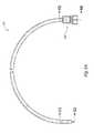
- FIG. 1Ais a perspective view of an example corrugated coaxial cable terminated on one end with an example compression connector
- FIG. 1Bis a perspective view of a portion of the example corrugated coaxial cable of FIG. 1A , the perspective view having portions of each layer of the example corrugated coaxial cable cut away;
- FIG. 1Cis a perspective view of a portion of an alternative corrugated coaxial cable, the perspective view having portions of each layer of the alternative corrugated coaxial cable cut away;
- FIG. 1Dis a cross-sectional side view of a terminal end of the example corrugated coaxial cable of FIG. 1A after having been prepared for termination with the example compression connector of FIG. 1A ;
- FIG. 2Ais a perspective view of the example compression connector of FIG. 1A ;
- FIG. 2Bis an exploded view of the example compression connector of FIG. 2A ;
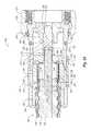
- FIG. 2Cis a cross-sectional side view of the example compression connector of FIG. 2A ;
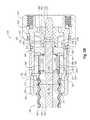
- FIG. 3Ais a cross-sectional side view of the terminal end of the example corrugated coaxial cable of FIG. 1D after having been inserted into the example compression connector of FIG. 2C , with the example compression connector being in an open position;
- FIG. 3Bis a cross-sectional side view of the terminal end of the example corrugated coaxial cable of FIG. 1D after having been inserted into the example compression connector of FIG. 3A , with the example compression connector being in an engaged position;
- FIG. 3Cis a cross-sectional side view of the terminal end of the example corrugated coaxial cable of FIG. 1D after having been inserted into another example compression, with the example compression connector being in an open position;
- FIG. 3Dis a cross-sectional side view of the terminal end of the example corrugated coaxial cable of FIG. 1D after having been inserted into the example compression connector of FIG. 3C , with the example compression connector being in an engaged position;
- FIG. 4Ais a chart of passive intermodulation (PIM) in a prior art coaxial cable compression connector
- FIG. 4Bis a chart of PIM in the example compression connector of FIG. 3B ;
- FIG. 5Ais a perspective view of an example smooth-walled coaxial cable terminated on one end with another example compression connector
- FIG. 5Bis a perspective view of a portion of the example smooth-walled coaxial cable of FIG. 5A , the perspective view having portions of each layer of the coaxial cable cut away;
- FIG. 5Cis a perspective view of a portion of an alternative smooth-walled coaxial cable, the perspective view having portions of each layer of the alternative coaxial cable cut away;
- FIG. 5Dis a cross-sectional side view of a terminal end of the example smooth-walled coaxial cable of FIG. 5A after having been prepared for termination with the example compression connector of FIG. 5A ;
- FIG. 6Ais a cross-sectional side view of the terminal end of the example smooth-walled coaxial cable of FIG. 5D after having been inserted into the example compression connector of FIG. 5A , with the example compression connector being in an open position;
- FIG. 6Bis a cross-sectional side view of the terminal end of the example smooth-walled coaxial cable of FIG. 5D after having been inserted into the example compression connector of FIG. 6A , with the example compression connector being in an engaged position;
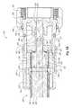
- FIG. 7Ais a perspective view of another example compression connector
- FIG. 7Bis an exploded view of the example compression connector of FIG. 7A ;
- FIG. 7Cis a cross-sectional side view of the example compression connector of FIG. 7A after having a terminal end of another example corrugated coaxial cable inserted into the example compression connector, with the example compression connector being in an open position;
- FIG. 7Dis a cross-sectional side view of the example compression connector of FIG. 7A after having the terminal end of the example corrugated coaxial cable of FIG. 7C inserted into the example compression connector, with the example compression connector being in an engaged position.
- Example embodiments of the present inventionrelate to coaxial cable connectors.
- the same reference numberswill be used throughout the drawings to refer to the same or like parts.
- These embodimentsare described in sufficient detail to enable those skilled in the art to practice the invention.
- Other embodimentsmay be utilized and structural, logical and electrical changes may be made without departing from the scope of the present invention.
- the various embodiments of the inventionalthough different, are not necessarily mutually exclusive.
- a particular feature, structure, or characteristic described in one embodimentmay be included within other embodiments.
- the following detailed descriptionis, therefore, not to be taken in a limiting sense, and the scope of the present invention is defined only by the appended claims, along with the full scope of equivalents to which such claims are entitled.
- the example coaxial cable 100has 50 Ohms of impedance and is a 1 ⁇ 2′′ series corrugated coaxial cable. It is understood, however, that these cable characteristics are example characteristics only, and that the example compression connectors disclosed herein can also benefit coaxial cables with other impedance, dimension, and shape characteristics.
- the example coaxial cable 100is terminated on the right side of FIG. 1A with an example compression connector 200 .
- the example compression connector 200is disclosed in FIG. 1A as a male compression connector, it is understood that the compression connector 200 can instead be configured as a female compression connector (not shown).
- the coaxial cable 100generally comprises an inner conductor 102 surrounded by an insulating layer 104 , a corrugated outer conductor 106 surrounding the insulating layer 104 , and a jacket 108 surrounding the corrugated outer conductor 106 .
- the phrase “surrounded by”refers to an inner layer generally being encased by an outer layer. However, it is understood that an inner layer may be “surrounded by” an outer layer without the inner layer being immediately adjacent to the outer layer. The term “surrounded by” thus allows for the possibility of intervening layers.
- the inner conductor 102is positioned at the core of the example coaxial cable 100 and may be configured to carry a range of electrical current (amperes) and/or RF/electronic digital signals.
- the inner conductor 102can be formed from copper, copper-clad aluminum (CCA), copper-clad steel (CCS), or silver-coated copper-clad steel (SCCCS), although other conductive materials are also possible.
- the inner conductor 102can be formed from any type of conductive metal or alloy.
- the inner conductor 102 of FIG. 1Bis clad, it could instead have other configurations such as solid, stranded, corrugated, plated, or hollow, for example.
- the insulating layer 104surrounds the inner conductor 102 , and generally serves to support the inner conductor 102 and insulate the inner conductor 102 from the outer conductor 106 .
- a bonding agentsuch as a polymer, may be employed to bond the insulating layer 104 to the inner conductor 102 .
- the insulating layer 104is formed from a foamed material such as, but not limited to, a foamed polymer or fluoropolymer.
- the insulating layer 104can be formed from foamed polyethylene (PE).
- the corrugated outer conductor 106surrounds the insulating layer 104 , and generally serves to minimize the ingress and egress of high frequency electromagnetic radiation to/from the inner conductor 102 .
- high frequency electromagnetic radiationis radiation with a frequency that is greater than or equal to about 50 MHz.
- the corrugated outer conductor 106can be formed from solid copper, solid aluminum, copper-clad aluminum (CCA), although other conductive materials are also possible.
- CCAcopper-clad aluminum
- the corrugated configuration of the corrugated outer conductor 106with peaks and valleys, enables the coaxial cable 100 to be flexed more easily than cables with smooth-walled outer conductors.
- the jacket 108surrounds the corrugated outer conductor 106 , and generally serves to protect the internal components of the coaxial cable 100 from external contaminants, such as dust, moisture, and oils, for example. In a typical embodiment, the jacket 108 also functions to limit the bending radius of the cable to prevent kinking, and functions to protect the cable (and its internal components) from being crushed or otherwise misshapen from an external force.
- the jacket 108can be formed from a variety of materials including, but not limited to, polyethylene (PE), high-density polyethylene (HDPE), low-density polyethylene (LDPE), linear low-density polyethylene (LLDPE), rubberized polyvinyl chloride (PVC), or some combination thereof. The actual material used in the formation of the jacket 108 might be indicated by the particular application/environment contemplated.
- an alternative coaxial cable 100 ′comprises an alternative insulating layer 104 ′ composed of a spiral-shaped spacer that enables the inner conductor 102 to be generally separated from the corrugated outer conductor 106 by air.
- the spiral-shaped spacer of the alternative insulating layer 104 ′may be formed from polyethylene or polypropylene, for example.
- the combined dielectric constant of the spiral-shaped spacer and the air in the alternative insulating layer 104 ′would be sufficient to insulate the inner conductor 102 from the corrugated outer conductor 106 in the alternative coaxial cable 100 ′.
- the example compression connector 200 disclosed hereincan similarly benefit the alternative coaxial cable 100 ′.
- a terminal end of the coaxial cable 100is disclosed after having been prepared for termination with the example compression connector 200 , disclosed in FIGS. 1 A and 2 A- 3 B.
- the terminal end of the coaxial cable 100comprises a first section 110 , a second section 112 , a cored-out section 114 , and an increased-diameter cylindrical section 116 .
- the jacket 108 , corrugated outer conductor 106 , and insulating layer 104have been stripped away from the first section 110 .
- the jacket 108has been stripped away from the second section 112 .
- the insulating layer 104has been cored out from the cored out section 114 .
- the diameter of a portion of the corrugated outer conductor 106 that surrounds the cored-out section 114has been increased so as to create the increased-diameter cylindrical section 116 of the outer conductor 106 .
- cylindricalrefers to a component having a section or surface with a substantially uniform diameter throughout the length of the section or surface. It is understood, therefore, that a “cylindrical” section or surface may have minor imperfections or irregularities in the roundness or consistency throughout the length of the section or surface. It is further understood that a “cylindrical” section or surface may have an intentional distribution or pattern of features, such as grooves or teeth, but nevertheless on average has a substantially uniform diameter throughout the length of the section or surface.
- This increasing of the diameter of the corrugated outer conductor 106can be accomplished using any of the tools disclosed in co-pending U.S. patent application Ser. No. 12/753,729, titled “COAXIAL CABLE PREPARATION TOOLS,” filed Apr. 2, 2010 and incorporated herein by reference in its entirety.
- this increasing of the diameter of the corrugated outer conductor 106can be accomplished using other tools, such as a common pipe expander.
- the increased-diameter cylindrical section 116can be fashioned by increasing a diameter of one or more of the valleys 106 a of the corrugated outer conductor 106 that surround the cored-out section 114 .
- the diameters of one or more of the valleys 106 acan be increased until they are equal to the diameters of the peaks 106 b , resulting in the increased-diameter cylindrical section 116 disclosed in FIG. 1D .
- the diameter of the increased-diameter cylindrical section 116 of the outer conductor 106can be greater than the diameter of the peaks 106 b of the example corrugated coaxial cable 100 .
- the diameter of the increased-diameter cylindrical section 116 of the outer conductor 106can be greater than the diameter of the valleys 106 a but less than the diameter of the peaks 106 b.
- the increased-diameter cylindrical section 116 of the corrugated outer conductor 106has a substantially uniform diameter throughout the length of the increased-diameter cylindrical section 116 . It is understood that the length of the increased-diameter cylindrical section 116 should be sufficient to allow a force to be directed inward on the increased-diameter cylindrical section 116 , once the corrugated coaxial cable 100 is terminated with the example compression connector 200 , with the inwardly-directed force having primarily a radial component and having substantially no axial component.
- the increased-diameter cylindrical section 116 of the corrugated outer conductor 106has a length greater than the distance 118 spanning the two adjacent peaks 106 b of the corrugated outer conductor 106 . More particularly, the length of the increased-diameter cylindrical section 116 is thirty three times the thickness 120 of the outer conductor 106 . It is understood, however, that the length of the increased-diameter cylindrical section 116 could be any length from two times the thickness 120 of the outer conductor 106 upward. It is further understood that the tools and/or processes that fashion the increased-diameter cylindrical section 116 may further create increased-diameter portions of the corrugated outer conductor 106 that are not cylindrical.
- the preparation of the terminal section of the example corrugated coaxial cable 100 disclosed in FIG. 1Dcan be accomplished by employing the example method 400 disclosed in co-pending U.S. patent application Ser. No. 12/753,742, titled “PASSIVE INTERMODULATION AND IMPEDANCE MANAGEMENT IN COAXIAL CABLE TERMINATIONS,” filed Apr. 2, 2010 and incorporated herein by reference in its entirety.
- the insulating layer 104is shown in FIG. 1D as extending all the way to the top of the peaks 106 b of the corrugated outer conductor 106 , it is understood that an air gap may exist between the insulating layer 104 and the top of the peaks 106 b .
- the jacket 108is shown in the FIG. 1D as extending all the way to the bottom of the valleys 106 a of the corrugated outer conductor 106 , it is understood that an air gap may exist between the jacket 108 and the bottom of the valleys 106 a.
- corrugated outer conductor 106can be either annular corrugated outer conductor, as disclosed in the figures, or can be helical corrugated outer conductor (not shown).
- the example compression connectors disclosed hereincan similarly benefit a coaxial cable with a helical corrugated outer conductor (not shown).
- the example compression connector 200comprises a connector nut 210 , a first o-ring seal 220 , a connector body 230 , a second o-ring seal 240 , a third o-ring seal 250 , an insulator 260 , a conductive pin 270 , a driver 280 , a mandrel 290 , a clamp 300 , a clamp ring 310 , a jacket seal 320 , and a compression sleeve 330 .
- the connector nut 210is connected to the connector body 230 via an annular flange 232 .
- the insulator 260positions and holds the conductive pin 270 within the connector body 230 .
- the conductive pin 270comprises a pin portion 272 at one end and a collet portion 274 at the other end.
- the collet portion 274comprises fingers 278 separated by slots 279 .
- the slots 279are configured to narrow or close as the compression connector 200 is moved from an open position (as disclosed in FIG. 3A ) to an engaged position (as disclosed in FIG. 3B ), as discussed in greater detail below.
- the collet portion 274is configured to receive and surround an inner conductor of a coaxial cable.
- the driver 280is positioned inside connector body 230 between the collet portion 274 of the conductive pin 270 and the mandrel 290 .
- the mandrel 290abuts the clamp 300 .
- the clamp 300abuts the clamp ring 310 , which abuts the jacket seal 320 , both of which are positioned within the compression sleeve 330 .
- the mandrel 290is an example of an internal connector structure as at least a portion of the mandrel 290 is configured to be positioned internal to a coaxial cable.
- the clamp 300is an example of an external connector structure as at least a portion of the clamp 300 is configured to be positioned external to a coaxial cable.
- the mandrel 290has a cylindrical outside surface 292 that is surrounded by a cylindrical inside surface 302 of the clamp 300 .
- the cylindrical outside surface 292cooperates with the cylindrical inside surface 302 to define a cylindrical gap 340 .
- the mandrel 290further has an inwardly-tapering outside surface 294 adjacent to one end of the cylindrical outside surface 292 , as well as an annular flange 296 adjacent to the other end of the cylindrical outside surface 292 .
- the clamp 300defines a slot 304 running the length of the clamp 300 .
- the slot 304is configured to narrow or close as the compression connector 200 is moved from an open position (as disclosed in FIG. 3A ) to an engaged position (as disclosed in FIG. 3B ), as discussed in greater detail below.
- the clamp 300further has an outwardly-tapering surface 306 adjacent to the cylindrical inside surface 302 .
- the clamp 300further has an inwardly-tapering outside transition surface 308 .
- portions of these surfacesmay be non-cylindrical.
- portions of these surfacesmay include steps, grooves, or ribs in order achieve mechanical and electrical contact with the increased-diameter cylindrical section 116 of the example coaxial cable 100 .
- the outside surface of the mandrel 290may include a rib that corresponds to a cooperating groove included on the inside surface of the clamp 300 .
- the compression of the increased-diameter cylindrical section 116 between the mandrel 290 and the clamp 300will cause the rib of the mandrel 290 to deform the increased-diameter cylindrical section 116 into the cooperating groove of the clamp 300 .
- Thiscan result in improved mechanical and/or electrical contact between the clamp 300 , the increased-diameter cylindrical section 116 , and the mandrel 290 .
- the locations of the rib and the cooperating groovecan also be reversed.
- the surfaces of the rib and the cooperating groovecan be cylindrical surfaces.
- multiple rib/cooperating groove pairsmay be included on the mandrel 290 and/or the clamp 300 . Therefore, the outside surface of the mandrel 290 and the inside surface of the clamp 300 are not limited to the configurations disclosed in the figures.
- FIG. 3Adiscloses the example compression connector 200 in an initial open position
- FIG. 3Bdiscloses the example compression connector 200 after having been moved into an engaged position.
- the terminal end of the corrugated coaxial cable 100 of FIG. 1Dcan be inserted into the example compression connector 200 through the compression sleeve 330 .
- the increased-diameter cylindrical section 116 of the outer conductor 106is received into the cylindrical gap 304 defined between the cylindrical outside surface 292 of the mandrel 290 and the cylindrical inside surface 302 of the clamp 300 .
- the jacket seal 320surrounds the jacket 108 of the corrugated coaxial cable 100 , and the inner conductor 102 is received into the collet portion 274 of the conductive pin 270 such that the conductive pin 270 is mechanically and electrically contacting the inner conductor 102 .
- the diameter 298 of the cylindrical outside surface 292 of the mandrel 290is greater than the smallest diameter 122 of the corrugated outer conductor 106 , which is the inside diameter of the valleys 106 a of the outer conductor 106 .
- FIG. 3Bdiscloses the example compression connector 200 after having been moved into an engaged position.
- the example compression connector 200is moved into the engaged position by sliding the compression sleeve 330 along the connector body 230 toward the connector nut 210 .
- the inside of the compression sleeve 330slides over the outside of the connector body 230 until a shoulder 332 of the compression sleeve 330 abuts a shoulder 234 of the connector body 230 .
- a distal end 334 of the compression sleeve 330compresses the third o-ring seal 250 into an annular groove 236 defined in the connector body 230 , thus sealing the compression sleeve 330 to the connector body 230 .
- a shoulder 336 of the compression sleeve 330axially biases against the jacket seal 320 , which axially biases against the clamp ring 310 , which axially forces the inwardly-tapering outside transition surface 308 of the clamp 300 against an outwardly-tapering inside surface 238 of the connector body 230 .
- the clamp 300is radially forced into the smaller diameter connector body 230 , which radially compresses the clamp 300 and thus reduces the outer diameter of the clamp 300 by narrowing or closing the slot 304 (see FIG. 2B ).
- the cylindrical inside surface 302 of the clamp 300is clamped around the increased-diameter cylindrical section 116 of the outer conductor 106 so as to radially compress the increased-diameter cylindrical section 116 between the cylindrical inside surface 302 of the clamp 300 and the cylindrical outside surface 292 of the mandrel 290 .
- the clamp 300axially biases against the annular flange 296 of the mandrel 290 , which axially biases against the conductive pin 270 , which axially forces the conductive pin 270 into the insulator 260 until a shoulder 276 of the collet portion 274 abuts a shoulder 262 of the insulator 260 .
- the fingers 278 of the collet portion 274are radially contracted around the inner conductor 102 by narrowing or closing the slots 279 (see FIG. 2B ).
- This radial contraction of the conductive pin 270results in an increased contact force between the conductive pin 270 and the inner conductor 102 , and can also result in some deformation of the inner conductor 102 , the insulator 260 , and/or the fingers 278 .
- the term “contact force”is the combination of the net friction and the net normal force between the surfaces of two components. This contracting configuration increases the reliability of the mechanical and electrical contact between the conductive pin 270 and the inner conductor 102 .
- the pin portion 272 of the conductive pin 270extends past the insulator 260 in order to engage a corresponding conductor of a female connector that is engaged with the connector nut 210 (not shown).
- FIGS. 3C and 3Daspects of another example compression connector 200 ′′ are disclosed.
- FIG. 3Cdiscloses the example compression connector 200 ′′ in an initial open position
- FIG. 3Ddiscloses the example compression connector 200 ′′ after having been moved into an engaged position.
- the example compression connector 200 ′′is identical to the example compression connector 200 in FIGS. 1 A and 2 A- 3 B, except that the example compression connector 200 ′′ has a modified insulator 260 ′′ and a modified conductive pin 270 ′′.
- the diameter of the portion of the inner conductor 102 that is configured to be received into the collet portion 274 ′′can be reduced.
- This additional diameter-reduction in the inner conductor 102enables the collet portion 274 ′′ to be modified to have the same or similar outside diameter as the pin portion 272 (excluding the taper at the tip of the pin portion 272 ), instead of the enlarged diameter of the collet portion 274 disclosed in FIGS. 3A and 3B .
- the outside diameter of the collet portion 274 ′′is substantially equal to the outside diameter of the inner conductor.
- This additional diameter-reduction in the inner conductor 102thus enables the outside diameter of the inner conductor 102 , through which the RF signal travels, to remain substantially constant at the transition between the inner conductor 102 and the conductive pin 270 ′′. Since impedance is a function of the diameter of the inner conductor, as discussed in greater detail below, this additional diameter-reduction in the inner conductor 102 can further improve impedance matching between the coaxial cable 100 and the compression connector 200 ′′.
- the distal end 239 of the connector body 230axially biases against the clamp ring 310 , which axially biases against the jacket seal 320 until a shoulder 312 of the clamp ring 310 abuts a shoulder 338 of the compression sleeve 330 .
- the axial force of the shoulder 336 of the compression sleeve 330 combined with the opposite axial force of the clamp ring 310axially compresses the jacket seal 320 causing the jacket seal 320 to become shorter in length and thicker in width.
- the thickened width of the jacket seal 320causes the jacket seal 320 to press tightly against the jacket 108 of the corrugated coaxial cable 100 , thus sealing the compression sleeve 330 to the jacket 108 of the corrugated coaxial cable 100 .
- the narrowest inside diameter 322 of the jacket seal 320which is equal to the outside diameter 124 of the valleys of jacket 108 , is less than the sum of the diameter 298 of the cylindrical outside surface 292 of the mandrel 290 plus two times the average thickness of the jacket 108 .
- the mandrel 290 and the clamp 300are both formed from metal, which makes the mandrel 290 and the clamp 300 relatively sturdy.
- two separate electrically conductive pathsexist between the outer conductor 106 and the connector body 230 . Although these two paths merge where the clamp 300 makes contact with the annular flange 296 of the mandrel 290 , as disclosed in FIG. 3B , it is understood that these paths may alternatively be separated by creating a substantial gap between the clamp 300 and the annular flange 296 . This substantial gap may further be filled or partially filled with an insulating material, such as a plastic washer for example, to better ensure electrical isolation between the clamp 300 and the annular flange 296 .
- an insulating materialsuch as a plastic washer for example
- the thickness of the metal inserted portion of the mandrel 290is about equal to the difference between the inside diameter of the peaks 106 b ( FIG. 1D ) of the corrugated outer conductor 106 and the inside diameter of the valleys 106 a ( FIG. 1D ) of the corrugated outer conductor 106 . It is understood, however, that the thickness of the metal inserted portion of the mandrel 290 could be greater than or less than the thickness disclosed in FIGS. 3A and 3B .
- one of the mandrel 290 or the clamp 300can alternatively be formed from a non-metal material such as polyetherimide (PEI) or polycarbonate, or from a metal/non-metal composite material such as a selectively metal-plated PEI or polycarbonate material.
- a selectively metal-plated mandrel 290 or clamp 300may be metal-plated at contact surfaces where the mandrel 290 or the clamp 300 makes contact with another component of the compression connector 200 .
- bridge platingsuch as one or more metal traces, can be included between these metal-plated contact surfaces in order to ensure electrical continuity between the contact surfaces. It is understood that only one of these two components needs to be formed from metal or from a metal/non-metal composite material in order to create a single electrically conductive path between the outer conductor 106 and the connector body 230 .
- the increased-diameter cylindrical section 116 of the outer conductor 106enables the inserted portion of the mandrel 290 to be relatively thick and to be formed from a material with a relatively high dielectric constant and still maintain favorable impedance characteristics. Also disclosed in FIGS. 3A and 3B , the metal inserted portion of the mandrel 290 has an inside diameter that is about equal to the inside diameter 122 of the valleys 106 a of the corrugated outer conductor 106 . It is understood, however, that the inside diameter of the metal inserted portion of the mandrel 290 could be greater than or less than the inside diameter disclosed in FIGS. 3A and 3B .
- the metal inserted portion of the mandrel 290can have an inside diameter that is about equal to an average diameter of the valleys 106 a and the peaks 106 b ( FIG. 1D ) of the corrugated outer conductor 106 .
- the mandrel 290replaces the material from which the insulating layer 104 is formed in the cored-out section 114 .
- This replacementchanges the dielectric constant of the material positioned between the inner conductor 102 and the outer conductor 106 in the cored-out section 114 . Since the impedance of the coaxial cable 100 is a function of the diameters of the inner and outer conductors 102 and 106 and the dielectric constant of the insulating layer 104 , in isolation this change in the dielectric constant would alter the impedance of the cored-out section 114 of the coaxial cable 100 .
- mandrel 290is formed from a material that has a significantly different dielectric constant from the dielectric constant of the insulating layer 104 , this change in the dielectric constant would, in isolation, significantly alter the impedance of the cored-out section 114 of the coaxial cable 100 .
- the increase of the diameter of the outer conductor 106 of the increased-diameter cylindrical section 116is configured to compensate for the difference in the dielectric constant between the removed insulating layer 104 and the inserted portion of the mandrel 290 in the cored-out section 114 . Accordingly, the increase of the diameter of the outer conductor 106 in the increased-diameter cylindrical section 116 enables the impedance of the cored-out section 114 to remain about equal to the impedance of the remainder of the coaxial cable 100 , thus reducing internal reflections and resulting signal loss associated with inconsistent impedance.
- the impedance z of the coaxial cable 100can be determined using Equation (1):
- ⁇is the dielectric constant of the material between the inner and outer conductors 102 and 106
- ⁇ OUTERis the effective inside diameter of the corrugated outer conductor 106
- ⁇ INNERis the outside diameter of the inner conductor 102 .
- the impedance z of the example coaxial cable 100should be maintained at 50 Ohms.
- the impedance z of the coaxial cableis formed at 50 Ohms by forming the example coaxial cable 100 with the following characteristics:
- the inside diameter of the cored-out section 114 of the outer conductor 106 ⁇ OUTER of 0.458 inchesis effectively replaced by the inside diameter of the mandrel 290 of 0.440 inches in order to maintain the impedance z of the cored-out section 114 of the coaxial cable 100 at 50 Ohms, with the following characteristics:
- the increase of the diameter of the outer conductor 106enables the mandrel 290 to be formed from metal and effectively replace the inside diameter of the cored-out section 114 of the outer conductor ⁇ OUTER . Further, the increase of the diameter of the outer conductor 106 also enables the mandrel 290 to alternatively be formed from a non-metal material having a dielectric constant that does not closely match the dielectric constant of the material from which the insulating layer 104 is formed.
- the particular increased diameter of the increased-diameter cylindrical section 116correlates to the shape and type of material from which the mandrel 290 is formed. It is understood that any change to the shape and/or material of the mandrel 290 may require a corresponding change to the diameter of the increased-diameter cylindrical section 116 .
- the increased diameter of the increased-diameter cylindrical section 116also facilitates an increase in the thickness of the mandrel 290 .
- the increased diameter of the increased-diameter cylindrical section 116also enables the mandrel 290 to be formed from a relatively sturdy material such as metal.
- the relatively sturdy mandrel 290in combination with the cylindrical configuration of the increased diameter cylindrical section 116 , enables a relative increase in the amount of radial force that can be directed inward on the increased-diameter cylindrical section 116 without collapsing the increased-diameter cylindrical section 116 or the mandrel 290 .
- the cylindrical configuration of the increased-diameter cylindrical section 116enables the inwardly-directed force to have primarily a radial component and have substantially no axial component, thus removing any dependency on a continuing axial force which can tend to decrease over time under extreme weather and temperature conditions. It is understood, however, that in addition to the primarily radial component directed to the increased-diameter cylindrical section 116 , the example compression connector 200 may additionally include one or more structures that exert an inwardly-directed force having an axial component on another section or sections of the outer conductor 106 .
- This relative increase in the amount of force that can be directed inward on the increased-diameter cylindrical section 116increases the security of the mechanical and electrical contacts between the mandrel 290 , the increased-diameter cylindrical section 116 , and the clamp 300 . Further, the contracting configuration of the insulator 260 and the conductive pin 270 increases the security of the mechanical and electrical contacts between the conductive pin 270 and the inner conductor 102 .
- FIG. 4Adiscloses a chart 350 showing the results of PIM testing performed on a coaxial cable that was terminated using a prior art compression connector.
- the PIM testing that produced the results in the chart 350was performed under dynamic conditions with impulses and vibrations applied to the prior art compression connector during the testing.
- the PIM levels of the prior art compression connectorwere measured on signals F1 and F2 to significantly vary across frequencies 1870-1910 MHz.
- the PIM levels of the prior art compression connectorfrequently exceeded a minimum acceptable industry standard of ⁇ 155 dBc.
- FIG. 4Bdiscloses a chart 375 showing the results of PIM testing performed on the coaxial cable 100 that was terminated using the example compression connector 200 .
- the PIM testing that produced the results in the chart 375was also performed under dynamic conditions with impulses and vibrations applied to the example compression connector 200 during the testing.
- the PIM levels of the example compression 200were measured on signals F1 and F2 to vary significantly less across frequencies 1870-1910 MHz. Further, the PIM levels of the example compression connector 200 remained well below the minimum acceptable industry standard of ⁇ 155 dBc.
- These superior PIM levels of the example compression connector 200are due at least in part to the cylindrical configurations of the increased-diameter cylindrical section 116 , the cylindrical outside surface 292 of the mandrel 290 , and the cylindrical inside surface 302 of the clamp 300 , as well as the contracting configuration of the insulator 260 and the conductive pin 270 .
- the relatively low PIM levels achieved using the example compression connector 200surpass the minimum acceptable level of ⁇ 155 dBc, thus reducing these interfering RF signals.
- the example field-installable compression connector 200enables coaxial cable technicians to perform terminations of coaxial cable in the field that have sufficiently low levels of PIM to enable reliable 4G wireless communication.
- the example field installable compression connector 200exhibits impedance matching and PIM characteristics that match or exceed the corresponding characteristics of less convenient factory-installed soldered or welded connectors on pre-fabricated jumper cables.
- a single design of the example compression connector 200can be field-installed on various manufacturers' coaxial cables despite slight differences in the cable dimensions between manufacturers. For example, even though each manufacturer's 1 ⁇ 2′′ series corrugated coaxial cable has a slightly different sinusoidal period length, valley diameter, and peak diameter in the corrugated outer conductor, the preparation of these disparate corrugated outer conductors to have a substantially identical increased-diameter cylindrical section 116 , as disclosed herein, enables each of these disparate cables to be terminated using a single compression connector 200 . Therefore, the design of the example compression connector 200 avoids the hassle of having to employ a different connector design for each different manufacturer's corrugated coaxial cable.
- the design of the various components of the example compression connector 200is simplified over prior art compression connectors. This simplified design enables these components to be manufactured and assembled into the example compression connector 200 more quickly and less expensively.
- the example coaxial cable 400also has 50 Ohms of impedance and is a 1 ⁇ 2′′ series smooth-walled coaxial cable. It is understood, however, that these cable characteristics are example characteristics only, and that the example compression connectors disclosed herein can also benefit coaxial cables with other impedance, dimension, and shape characteristics.
- the example coaxial cable 400is also terminated on the right side of FIG. 5A with an example compression connector 200 ′ that is identical to the example compression connector 200 in FIGS. 1 A and 2 A- 3 B, except that the example compression connector 200 ′ has a different jacket seal, as shown and discussed below in connection with FIGS. 6A and 6B .
- the example coaxial cable 400could be configured to be terminated with the example compression connector 200 instead of the example compression connector 200 ′.
- the jacket seal of the example compression connector 200can function to seal both types of cable. Therefore, a single compression connector can be used to terminate both types of cable.
- the coaxial cable 400generally comprises an inner conductor 402 surrounded by an insulating layer 404 , a smooth-walled outer conductor 406 surrounding the insulating layer 404 , and a jacket 408 surrounding the smooth-walled outer conductor 406 .
- the inner conductor 402 and insulating layer 404are identical in form and function to the inner conductor 102 and insulating layer 104 , respectively, of the example coaxial cable 100 .
- the smooth-walled outer conductor 406 and jacket 408are identical in form and function to the corrugated outer conductor 106 and jacket 108 , respectively, of the example coaxial cable 400 , except that the outer conductor 406 and jacket 408 are smooth walled instead of corrugated.
- the smooth-walled configuration of the outer conductor 406enables the coaxial cable 400 to be generally more rigid than cables with corrugated outer conductors.
- an alternative coaxial cable 400 ′comprises an alternative insulating layer 404 ′ composed of a spiral-shaped spacer that is identical in form and function to the alternative insulating layer 104 ′ of FIG. 1C . Accordingly, the example compression connector 200 ′ disclosed herein can similarly benefit the alternative coaxial cable 400 ′.
- a terminal end of the coaxial cable 400is disclosed after having been prepared for termination with the example compression connector 200 ′, disclosed in FIGS. 5 A and 6 A- 6 B.
- the terminal end of the coaxial cable 400comprises a first section 410 , a second section 412 , a cored-out section 414 , and an increased-diameter cylindrical section 416 .
- the jacket 408 , smooth-walled outer conductor 406 , and insulating layer 404have been stripped away from the first section 410 .
- the jacket 408has been stripped away from the second section 412 .
- the insulating layer 404has been cored out from the cored out section 414 .
- the diameter of a portion of the smooth-walled outer conductor 406 that surrounds the cored-out section 414has been increased so as to create the increased-diameter cylindrical section 416 of the outer conductor 406 .
- This increasing of the diameter of the smooth-walled outer conductor 406can be accomplished as discussed above in connection with the increasing of the diameter of the corrugated outer conductor 106 in FIG. 1D .
- the increased-diameter cylindrical section 416 of the smooth-walled outer conductor 406has a substantially uniform diameter throughout the length of the section 416 .
- the length of the increased-diameter cylindrical section 416should be sufficient to allow a force to be directed inward on the increased-diameter cylindrical section 416 , once the smooth-walled coaxial cable 400 is terminated with the example compression connector 200 ′, with the inwardly directed force having primarily a radial component and having substantially no axial component.
- the length of the increased-diameter cylindrical section 416is thirty-three times the thickness 418 of the outer conductor 406 . It is understood, however, that the length of the increased-diameter cylindrical section 416 could be any length from two times the thickness 418 of the outer conductor 406 upward. It is further understood that the tools and/or processes that fashion the increased-diameter cylindrical section 416 may further create increased diameter portions of the smooth-walled outer conductor 406 that are not cylindrical.
- the preparation of the terminal section of the example smooth-walled coaxial cable 400 disclosed in FIG. 5Dcan be accomplished as discussed above in connection with the example corrugated coaxial cable 100 .
- FIGS. 6A and 6Baspects of the operation of the example compression connector 200 ′ are disclosed.
- FIG. 6Adiscloses the example compression connector 200 ′ in an initial open position
- FIG. 6Bdiscloses the example compression connector 200 ′ after having been moved into an engaged position.
- the terminal end of the smooth-walled coaxial cable 400 of FIG. 5Dcan be inserted into the example compression connector 200 ′ through the compression sleeve 330 .
- the increased-diameter cylindrical section 416 of the outer conductor 406is received into the cylindrical gap 304 defined between the cylindrical outside surface 292 of the mandrel 290 and the cylindrical inside surface 302 of the clamp 300 .
- the jacket seal 320 ′surrounds the jacket 408 of the smooth-walled coaxial cable 400 , and the inner conductor 402 is received into the collet portion 274 of the conductive pin 270 such that the conductive pin 270 is mechanically and electrically contacting the inner conductor 402 .
- the diameter 298 of the cylindrical outside surface 292 of the mandrel 290is greater than the smallest diameter 420 of the smooth-walled outer conductor 406 , which is the inside diameter of the outer conductor 406 .
- the jacket seal 320 ′has an inside diameter 322 ′ that is less than the sum of the diameter 298 of the cylindrical outside surface 292 of the mandrel 290 plus two times the thickness of the jacket 408 .
- FIG. 6Bdiscloses the example compression connector 200 ′ after having been moved into an engaged position.
- the example compression connector 200 ′is moved into an engaged position in an identical fashion as discussed above in connection with the example compression connector 200 in FIGS. 3A and 3B .
- the clamp 300is radially compressed by the axial force exerted on the compression sleeve 330 and the cylindrical inside surface 302 of the clamp 300 is clamped around the increased diameter cylindrical section 416 of the outer conductor 406 so as to radially compress the increased-diameter cylindrical section 416 between the cylindrical inside surface 302 of the clamp 300 and the cylindrical outside surface 292 of the mandrel 290 .
- the compression connector 200 ′As the compression connector 200 ′ is moved into the engaged position, the axial force of the shoulder 336 of the compression sleeve 330 combined with the opposite axial force of the clamp ring 310 axially compresses the jacket seal 320 ′ causing the jacket seal 320 ′ to become shorter in length and thicker in width.
- the thickened width of the jacket seal 320 ′causes the jacket seal 320 ′ to press tightly against the jacket 408 of the smooth-walled coaxial cable 400 , thus sealing the compression sleeve 330 to the jacket 408 of the smooth-walled coaxial cable 400 .
- the narrowest inside diameter 322 ′ of the jacket seal 320 ′which is equal to the outside diameter 124 ′ of the jacket 408 , is less than the sum of the diameter 298 of the cylindrical outside surface 292 of the mandrel 290 plus two times the thickness of the jacket 408 .
- the termination of the smooth-walled coaxial cable 400 using the example compression connector 200 ′enables the impedance of the cored-out section 414 to remain about equal to the impedance of the remainder of the coaxial cable 400 , thus reducing internal reflections and resulting signal loss associated with inconsistent impedance.
- the termination of the smooth-walled coaxial cable 400 using the example compression connector 200 ′enables improved mechanical and electrical contacts between the mandrel 290 , the increased-diameter cylindrical section 416 , and the clamp 290 , as well as between the inner conductor 402 and the conductive pin 270 , which reduces the PIM levels and associated creation of interfering RF signals that emanate from the example compression connector 200 ′.
- the example compression connector 500is configured to terminate either smooth-walled or corrugated 50 Ohm 7 ⁇ 8′′ series coaxial cable. Further, although the example compression connector 500 is disclosed in FIG. 7A as a female compression connector, it is understood that the compression connector 500 can instead be configured as a male compression connector (not shown).
- the example compression connector 500comprises a connector body 510 , a first o-ring seal 520 , a second o-ring seal 525 , a first insulator 530 , a conductive pin 540 , a guide 550 , a second insulator 560 , a mandrel 590 , a clamp 600 , a clamp ring 610 , a jacket seal 620 , and a compression sleeve 630 .
- the connector body 510 , first o-ring seal 520 , second o-ring seal 525 mandrel 590 , clamp 600 , clamp ring 610 , jacket seal 620 , and compression sleeve 630function similarly to the connector body 230 , second o-ring seal, third o-ring seal 250 , mandrel 290 , clamp 300 , clamp ring 310 , jacket seal 320 , and compression sleeve 330 , respectively.
- the first insulator 530 , conductive pin 540 , guide 550 , and second insulator 560function similarly to the insulator 13 , pin 14 , guide 15 , and insulator 16 disclosed in U.S. Pat. No. 7,527,512, titled “CABLE CONNECTOR EXPANDING CONTACT,” which issued May 5, 2009 and is incorporated herein by reference in its entirety.
- the conductive pin 540comprises a plurality of fingers 542 separated by a plurality of slots 544 .
- the guide 550comprises a plurality of corresponding tabs 552 that correspond to the plurality of slots 544 .
- Each finger 542comprises a ramped portion 546 (see FIG. 7C ) on an underside of the finger 542 which is configured to interact with a ramped portion 554 of the guide 550 .
- the second insulator 560is press fit into a groove 592 formed in the mandrel 590 .
- FIG. 7Cdiscloses the example compression connector in an open position.
- FIG. 7Ddiscloses the example compression connector 500 in an engaged position.
- a terminal end of an example corrugated coaxial cable 700can be inserted into the example compression connector 500 through the compression sleeve 630 .
- the example compression connector 500can also be employed in connection with a smooth-walled coaxial cable (not shown). Once inserted, portions of the guide 550 and the conductive pin 540 can slide easily into the hollow inner conductor 702 of the coaxial cable 700 .
- the conductive pin 540is forced into the inner conductor 702 beyond the ramped portions 554 of the guide 550 due to the interaction of the tabs 552 and the second insulator 560 , which causes the conductive pin 540 to slide with respect to the guide 550 .
- This sliding actionforces the fingers 542 to radially expand due to the ramped portions 546 interacting with the ramped portion 554 .
- This radial expansion of the conductive pin 540results in an increased contact force between the conductive pin 540 and the inner conductor 702 , and can also result in some deformation of the inner conductor 702 , the guide 550 , and/or the fingers 542 .
- This expanding configurationincreases the reliability of the mechanical and electrical contact between the conductive pin 540 and the inner conductor 702 .
- the termination of the corrugated coaxial cable 700 using the example compression connector 500enables the impedance of the cored-out section 714 of the cable 700 to remain about equal to the impedance of the remainder of the cable 700 , thus reducing internal reflections and resulting signal loss associated with inconsistent impedance. Further, the termination of the corrugated coaxial cable 700 using the example compression connector 500 enables improved mechanical and electrical contacts between the mandrel 590 , the increased-diameter cylindrical section 716 , and the clamp 600 , as well as between the inner conductor 702 and the conductive pin 540 , which reduces the PIM levels and associated creation of interfering RF signals that emanate from the example compression connector 500 .
Landscapes
- Coupling Device And Connection With Printed Circuit (AREA)
Abstract
Description
where ∈ is the dielectric constant of the material between the inner and
Claims (51)
Priority Applications (1)
| Application Number | Priority Date | Filing Date | Title |
|---|---|---|---|
| US13/948,897US8591253B1 (en) | 2010-04-02 | 2013-07-23 | Cable compression connectors |
Applications Claiming Priority (4)
| Application Number | Priority Date | Filing Date | Title |
|---|---|---|---|
| US12/753,735US7934954B1 (en) | 2010-04-02 | 2010-04-02 | Coaxial cable compression connectors |
| US13/093,937US8388375B2 (en) | 2010-04-02 | 2011-04-26 | Coaxial cable compression connectors |
| US13/784,499US8708737B2 (en) | 2010-04-02 | 2013-03-04 | Cable connectors having a jacket seal |
| US13/948,897US8591253B1 (en) | 2010-04-02 | 2013-07-23 | Cable compression connectors |
Related Parent Applications (2)
| Application Number | Title | Priority Date | Filing Date |
|---|---|---|---|
| US13/093,937ContinuationUS8388375B2 (en) | 2010-04-02 | 2011-04-26 | Coaxial cable compression connectors |
| US13/784,499ContinuationUS8708737B2 (en) | 2010-04-02 | 2013-03-04 | Cable connectors having a jacket seal |
Publications (2)
| Publication Number | Publication Date |
|---|---|
| US8591253B1true US8591253B1 (en) | 2013-11-26 |
| US20130316575A1 US20130316575A1 (en) | 2013-11-28 |
Family
ID=43903256
Family Applications (7)
| Application Number | Title | Priority Date | Filing Date |
|---|---|---|---|
| US12/753,735ActiveUS7934954B1 (en) | 2010-04-02 | 2010-04-02 | Coaxial cable compression connectors |
| US13/093,937ActiveUS8388375B2 (en) | 2010-04-02 | 2011-04-26 | Coaxial cable compression connectors |
| US13/784,499ActiveUS8708737B2 (en) | 2010-04-02 | 2013-03-04 | Cable connectors having a jacket seal |
| US13/948,897ActiveUS8591253B1 (en) | 2010-04-02 | 2013-07-23 | Cable compression connectors |
| US13/963,344ActiveUS8602818B1 (en) | 2010-04-02 | 2013-08-09 | Compression connector for cables |
| US13/963,544ActiveUS8591254B1 (en) | 2010-04-02 | 2013-08-09 | Compression connector for cables |
| US14/200,605Expired - Fee RelatedUS8956184B2 (en) | 2010-04-02 | 2014-03-07 | Coaxial cable connector |
Family Applications Before (3)
| Application Number | Title | Priority Date | Filing Date |
|---|---|---|---|
| US12/753,735ActiveUS7934954B1 (en) | 2010-04-02 | 2010-04-02 | Coaxial cable compression connectors |
| US13/093,937ActiveUS8388375B2 (en) | 2010-04-02 | 2011-04-26 | Coaxial cable compression connectors |
| US13/784,499ActiveUS8708737B2 (en) | 2010-04-02 | 2013-03-04 | Cable connectors having a jacket seal |
Family Applications After (3)
| Application Number | Title | Priority Date | Filing Date |
|---|---|---|---|
| US13/963,344ActiveUS8602818B1 (en) | 2010-04-02 | 2013-08-09 | Compression connector for cables |
| US13/963,544ActiveUS8591254B1 (en) | 2010-04-02 | 2013-08-09 | Compression connector for cables |
| US14/200,605Expired - Fee RelatedUS8956184B2 (en) | 2010-04-02 | 2014-03-07 | Coaxial cable connector |
Country Status (6)
| Country | Link |
|---|---|
| US (7) | US7934954B1 (en) |
| CN (2) | CN202205994U (en) |
| CA (1) | CA2795254A1 (en) |
| DE (2) | DE202011000776U1 (en) |
| TW (1) | TW201140953A (en) |
| WO (1) | WO2011123828A2 (en) |
Cited By (4)
| Publication number | Priority date | Publication date | Assignee | Title |
|---|---|---|---|---|
| US20130183856A1 (en)* | 2012-01-12 | 2013-07-18 | John Mezzalingua Associates, Inc. | Center conductor engagement mechanism |
| US20130203287A1 (en)* | 2012-02-06 | 2013-08-08 | John Mezzalingua Associates, Inc. | Port assembly connector for engaging a coaxial cable and an outer conductor |
| US20130224993A1 (en)* | 2011-03-25 | 2013-08-29 | Ppc Broadband, Inc. | Coaxial cable connector |
| US20140127941A1 (en)* | 2012-11-08 | 2014-05-08 | Yueh-Chiung Lu | Aluminum tube coaxial cable connector |
Families Citing this family (88)
| Publication number | Priority date | Publication date | Assignee | Title |
|---|---|---|---|---|
| US8113875B2 (en) | 2008-09-30 | 2012-02-14 | Belden Inc. | Cable connector |
| US9017101B2 (en) | 2011-03-30 | 2015-04-28 | Ppc Broadband, Inc. | Continuity maintaining biasing member |
| US8287320B2 (en) | 2009-05-22 | 2012-10-16 | John Mezzalingua Associates, Inc. | Coaxial cable connector having electrical continuity member |
| US9570845B2 (en) | 2009-05-22 | 2017-02-14 | Ppc Broadband, Inc. | Connector having a continuity member operable in a radial direction |
| EP2438655A1 (en)* | 2009-06-05 | 2012-04-11 | Andrew LLC | Slip ring contact coaxial connector |
| US7934954B1 (en) | 2010-04-02 | 2011-05-03 | John Mezzalingua Associates, Inc. | Coaxial cable compression connectors |
| US8468688B2 (en) | 2010-04-02 | 2013-06-25 | John Mezzalingua Associates, LLC | Coaxial cable preparation tools |
| US9166306B2 (en) | 2010-04-02 | 2015-10-20 | John Mezzalingua Associates, LLC | Method of terminating a coaxial cable |
| US8177582B2 (en) | 2010-04-02 | 2012-05-15 | John Mezzalingua Associates, Inc. | Impedance management in coaxial cable terminations |
| TWI549386B (en) | 2010-04-13 | 2016-09-11 | 康寧吉伯特公司 | Coaxial connector with inhibited ingress and improved grounding |
| DE102010014981A1 (en)* | 2010-04-14 | 2011-10-20 | Pfisterer Kontaktsysteme Gmbh | Device for electrically connecting a cable, in particular plug connection part |
| US8454385B2 (en)* | 2010-06-22 | 2013-06-04 | John Mezzalingua Associates, LLC | Coaxial cable connector with strain relief clamp |
| US8337229B2 (en) | 2010-11-11 | 2012-12-25 | John Mezzalingua Associates, Inc. | Connector having a nut-body continuity element and method of use thereof |
| US8157588B1 (en) | 2011-02-08 | 2012-04-17 | Belden Inc. | Cable connector with biasing element |
| US8366481B2 (en) | 2011-03-30 | 2013-02-05 | John Mezzalingua Associates, Inc. | Continuity maintaining biasing member |
| US9711917B2 (en) | 2011-05-26 | 2017-07-18 | Ppc Broadband, Inc. | Band spring continuity member for coaxial cable connector |
| US9203167B2 (en) | 2011-05-26 | 2015-12-01 | Ppc Broadband, Inc. | Coaxial cable connector with conductive seal |
| US8591244B2 (en) | 2011-07-08 | 2013-11-26 | Ppc Broadband, Inc. | Cable connector |
| US20130072057A1 (en) | 2011-09-15 | 2013-03-21 | Donald Andrew Burris | Coaxial cable connector with integral radio frequency interference and grounding shield |
| US8727807B2 (en)* | 2011-10-28 | 2014-05-20 | Tyco Electronics Corporation | Coaxial connector |
| US9124010B2 (en)* | 2011-11-30 | 2015-09-01 | Ppc Broadband, Inc. | Coaxial cable connector for securing cable by axial compression |
| US9136654B2 (en) | 2012-01-05 | 2015-09-15 | Corning Gilbert, Inc. | Quick mount connector for a coaxial cable |
| US9083113B2 (en)* | 2012-01-11 | 2015-07-14 | John Mezzalingua Associates, LLC | Compression connector for clamping/seizing a coaxial cable and an outer conductor |
| US8859899B2 (en)* | 2012-02-10 | 2014-10-14 | Itt Manufacturing Enterprises, Llc | Electrical connector for cables |
| US9136629B2 (en)* | 2012-07-19 | 2015-09-15 | Holland Electronics, Llc | Moving part coaxial cable connectors |
| US9923308B2 (en) | 2012-04-04 | 2018-03-20 | Holland Electronics, Llc | Coaxial connector with plunger |
| US9130288B2 (en) | 2012-07-19 | 2015-09-08 | Holland Electronics, Llc | Moving part coaxial cable connector |
| US9627814B2 (en) | 2012-04-04 | 2017-04-18 | Holland Electronics Llc | Moving part coaxial connectors |
| DE102012107406A1 (en)* | 2012-08-10 | 2014-05-15 | Endress + Hauser Gmbh + Co. Kg | Connection device with shielding contact |
| US9257780B2 (en) | 2012-08-16 | 2016-02-09 | Ppc Broadband, Inc. | Coaxial cable connector with weather seal |
| CN102801063B (en)* | 2012-08-16 | 2015-11-25 | 中航光电科技股份有限公司 | Connecting cable radio frequency (RF) coaxial connector |
| CN202855959U (en)* | 2012-08-27 | 2013-04-03 | 常州安费诺福洋通信设备有限公司 | One-body type crimping connector |
| US9312609B2 (en)* | 2012-10-11 | 2016-04-12 | John Mezzalingua Associates, LLC | Coaxial cable device and method involving weld and mate connectivity |
| US9384872B2 (en)* | 2012-10-11 | 2016-07-05 | John Mezzalingua Associates, LLC | Coaxial cable device and method involving weld connectivity |
| US9633765B2 (en)* | 2012-10-11 | 2017-04-25 | John Mezzalingua Associates, LLC | Coaxial cable device having a helical outer conductor and method for effecting weld connectivity |
| US9287659B2 (en) | 2012-10-16 | 2016-03-15 | Corning Optical Communications Rf Llc | Coaxial cable connector with integral RFI protection |
| CN105284015B (en) | 2013-05-20 | 2019-03-08 | 康宁光电通信Rf有限责任公司 | Coaxial cable connector with whole RFI protection |
| US9793624B2 (en)* | 2013-12-24 | 2017-10-17 | Ppc Broadband, Inc. | Connector having an inner conductor engager |
| AR099038A1 (en) | 2014-01-08 | 2016-06-22 | General Cable Tech Corp | COVERED AIR CONDUCTOR |
| EP3097612B1 (en)* | 2014-01-20 | 2018-08-22 | Schneider Electric IT Corporation | Busbar connector assembly and securing method thereof |
| US9484646B2 (en)* | 2014-01-21 | 2016-11-01 | Ppc Broadband, Inc. | Cable connector structured for reassembly and method thereof |
| US9510489B2 (en)* | 2014-02-23 | 2016-11-29 | Cinch Connectivity Solutions, Inc. | High isolation grounding device |
| EP3108543B1 (en)* | 2014-02-23 | 2020-03-25 | Cinch Connectivity Solutions, Inc. | High isolation grounding device |
| US9653823B2 (en)* | 2014-05-19 | 2017-05-16 | Ppc Broadband, Inc. | Connector having installation-responsive compression |
| US9419388B2 (en)* | 2014-05-30 | 2016-08-16 | Ppc Broadband, Inc. | Transition device for coaxial cables |
| GB2530708B (en)* | 2014-07-11 | 2020-02-12 | Hughes Electronics Ltd | A low PIM passive connection system for cellular networks |
| EP3195329A4 (en)* | 2014-08-05 | 2018-03-07 | General Cable Technologies Corporation | Fluoro copolymer coatings for overhead conductors |
| WO2016073309A1 (en) | 2014-11-03 | 2016-05-12 | Corning Optical Communications Rf Llc | Coaxial cable connector with integral rfi protection |
| US9633761B2 (en)* | 2014-11-25 | 2017-04-25 | John Mezzalingua Associates, LLC | Center conductor tip |
| CN104466348A (en)* | 2014-12-10 | 2015-03-25 | 安徽蓝麦通信科技有限公司 | Low-intermodulation antenna feeder connector |
| DE202015000750U1 (en)* | 2015-01-30 | 2015-02-25 | Rosenberger Hochfrequenztechnik Gmbh & Co. Kg | Connector assembly with compensation sleeve |
| US9647384B2 (en)* | 2015-02-09 | 2017-05-09 | Commscope Technologies Llc | Back body for coaxial connector |
| US10033122B2 (en) | 2015-02-20 | 2018-07-24 | Corning Optical Communications Rf Llc | Cable or conduit connector with jacket retention feature |
| US10418760B2 (en)* | 2015-06-10 | 2019-09-17 | Ppc Broadband, Inc. | Coaxial cable connector having an outer conductor engager |
| US11217948B2 (en)* | 2015-06-10 | 2022-01-04 | Ppc Broadband, Inc. | Connector for engaging an outer conductor of a coaxial cable |
| US9711918B2 (en)* | 2015-06-10 | 2017-07-18 | Ppc Broadband, Inc. | Coaxial cable connector having an outer conductor engager |
| US10431942B2 (en)* | 2015-06-10 | 2019-10-01 | Ppc Broadband, Inc. | Coaxial cable connector having an outer conductor engager |
| CN104934814B (en)* | 2015-06-30 | 2017-04-05 | 北京无线电计量测试研究所 | A kind of high temperature resistant no-welding type connector for radio-frequency coaxial cable |
| US10211547B2 (en)* | 2015-09-03 | 2019-02-19 | Corning Optical Communications Rf Llc | Coaxial cable connector |
| US20170110224A1 (en)* | 2015-10-16 | 2017-04-20 | New Green Co., Ltd. | Cable fixator |
| CA3004844C (en) | 2015-11-13 | 2022-06-28 | General Cable Technologies Corporation | Cables coated with fluorocopolymer coatings |
| US9525220B1 (en) | 2015-11-25 | 2016-12-20 | Corning Optical Communications LLC | Coaxial cable connector |
| US9583933B1 (en) | 2015-12-17 | 2017-02-28 | Itt Manufacturing Enterprises Llc | Mineral insulated cable terminations |
| US10128594B2 (en) | 2015-12-22 | 2018-11-13 | Biosense Webster (Israel) Ltd. | Connectors having three-dimensional surfaces |
| US9905956B2 (en)* | 2015-12-22 | 2018-02-27 | Biosense Webster (Israel) Ltd. | Preventing unwanted contact between terminals |
| CN106981795B (en)* | 2016-01-15 | 2020-07-31 | 康普技术有限责任公司 | Cable-connector assembly with heat shrink sleeve |
| EP3242359B1 (en)* | 2016-05-04 | 2019-07-17 | MD Elektronik GmbH | Cable |
| CN105870738A (en)* | 2016-06-12 | 2016-08-17 | 镇江华浩通信器材有限公司 | Novel N type radio frequency coaxial connector for protecting cable welding position |
| CN108574145B (en)* | 2017-03-08 | 2021-06-29 | 康普技术有限责任公司 | Corrugated Cable Coaxial Connector |
| US10490915B2 (en)* | 2017-06-07 | 2019-11-26 | Mitas Electronics, Llc | Gaussian chamber cable direct connector |
| CN107800009B (en)* | 2017-09-28 | 2023-09-29 | 江苏亨鑫科技有限公司 | Quick installation mechanism of radio frequency coaxial cable connector |
| WO2019074470A1 (en) | 2017-10-09 | 2019-04-18 | Keysight Technologies, Inc. | Hybrid coaxial cable fabrication |
| US10205268B1 (en)* | 2017-12-21 | 2019-02-12 | Aptiv Technologies Limited | Electrical connector having cable seals providing electromagnetic shielding |
| JP6954170B2 (en)* | 2018-02-15 | 2021-10-27 | 株式会社オートネットワーク技術研究所 | Terminal |
| WO2019183644A1 (en) | 2018-03-23 | 2019-09-26 | Ppc Broadband, Inc. | Flexible fiber node connector |
| US11695237B2 (en)* | 2018-04-17 | 2023-07-04 | John Mezzalingua Associates, LLC | Annular abutment/alignment guide for cable connectors |
| CN108736202A (en)* | 2018-07-16 | 2018-11-02 | 浙江德通科技有限公司 | Novel coaxial cable connector |
| CN108777392B (en)* | 2018-08-07 | 2021-03-16 | 江苏亨鑫科技有限公司 | High-reliability radio frequency coaxial connector capable of being quickly disassembled and assembled |
| EP3935694B1 (en)* | 2019-03-08 | 2024-04-03 | Huber+Suhner Ag | Coaxial connector and cable assembly |
| CN112510434A (en)* | 2019-09-16 | 2021-03-16 | 康普技术有限责任公司 | Coaxial connector with axially floating inner contact |
| JP7379085B2 (en)* | 2019-10-25 | 2023-11-14 | タイコエレクトロニクスジャパン合同会社 | Crimp structure |
| CN112787182A (en)* | 2019-11-05 | 2021-05-11 | 康普技术有限责任公司 | Cable connector and cable assembly |
| CN111900572B (en)* | 2020-06-15 | 2021-12-28 | 上海航天科工电器研究院有限公司 | Radio frequency connector matched with ultra-flexible threaded cable for multiple waterproof intermodulation stabilization |
| CN111834841B (en)* | 2020-06-15 | 2021-11-19 | 上海航天科工电器研究院有限公司 | Radio frequency connector adapted to waveform cable |
| CN112201977B (en)* | 2020-09-27 | 2022-04-26 | 中天射频电缆有限公司 | Mounting structure of cable leakage connector and cable leakage connector |
| WO2023064648A1 (en)* | 2021-10-12 | 2023-04-20 | Commscope Technologies Llc | Coaxial connector assemblies |
| CN115452226B (en)* | 2022-10-05 | 2023-12-19 | 大连理工大学 | Cable force recognition algorithm considering semi-rigid constraint at two ends |
| CN116381292B (en)* | 2023-06-05 | 2023-08-01 | 广东电网有限责任公司珠海供电局 | A single-core cable characteristic impedance measurement fixture, measurement system and measurement method |
Citations (223)
| Publication number | Priority date | Publication date | Assignee | Title |
|---|---|---|---|---|
| US2258737A (en) | 1939-01-19 | 1941-10-14 | Emi Ltd | Plug and socket connection |
| US2785384A (en) | 1955-02-23 | 1957-03-12 | Liquidometer Corp | Moisture proof means for connecting a coaxial cable to a fitting |
| US3022482A (en) | 1956-06-12 | 1962-02-20 | Bird Electronic Corp | Coaxial line transition section and method of making same |
| US3076169A (en) | 1959-04-21 | 1963-01-29 | Kenneth L Blaisdell | Coaxial cable connectors |
| US3184706A (en) | 1962-09-27 | 1965-05-18 | Itt | Coaxial cable connector with internal crimping structure |
| US3221290A (en) | 1963-03-21 | 1965-11-30 | Amp Inc | Coaxial connector featuring an improved seal |
| US3275913A (en) | 1964-11-20 | 1966-09-27 | Lrc Electronics Inc | Variable capacitor |
| US3297979A (en) | 1965-01-05 | 1967-01-10 | Amp Inc | Crimpable coaxial connector |
| US3321732A (en) | 1965-05-14 | 1967-05-23 | Amp Inc | Crimp type coaxial connector assembly |
| US3355698A (en) | 1965-04-28 | 1967-11-28 | Amp Inc | Electrical connector |
| US3372364A (en) | 1965-09-10 | 1968-03-05 | Amp Inc | Coaxial connector |
| US3406373A (en) | 1966-07-26 | 1968-10-15 | Amp Inc | Coaxial connector assembly |
| US3498647A (en) | 1967-12-01 | 1970-03-03 | Karl H Schroder | Connector for coaxial tubes or cables |
| US3539976A (en) | 1968-01-04 | 1970-11-10 | Amp Inc | Coaxial connector with controlled characteristic impedance |
| US3581269A (en) | 1969-03-11 | 1971-05-25 | Bell Telephone Labor Inc | Connector for coaxial cable |
| US3629792A (en) | 1969-01-28 | 1971-12-21 | Bunker Ramo | Wire seals |
| US3671926A (en) | 1970-08-03 | 1972-06-20 | Lindsay Specialty Prod Ltd | Coaxial cable connector |
| US3671922A (en) | 1970-08-07 | 1972-06-20 | Bunker Ramo | Push-on connector |
| US3678446A (en) | 1970-06-02 | 1972-07-18 | Atomic Energy Commission | Coaxial cable connector |
| US3686623A (en) | 1968-11-26 | 1972-08-22 | Bunker Ramo | Coaxial cable connector plug |
| US3710005A (en) | 1970-12-31 | 1973-01-09 | Mosley Electronics Inc | Electrical connector |
| US3744011A (en) | 1971-10-28 | 1973-07-03 | Itt | Coaxial cable connector |
| US3757279A (en) | 1972-05-15 | 1973-09-04 | Jerrold Electronics Corp | Tor diameters electrical connector operable for diverse coaxial cable center conduc |
| US3764959A (en) | 1972-07-18 | 1973-10-09 | Astrolab | Universal coaxial cable connector |
| US3845453A (en) | 1973-02-27 | 1974-10-29 | Bendix Corp | Snap-in contact assembly for plug and jack type connectors |
| US3879102A (en) | 1973-12-10 | 1975-04-22 | Gamco Ind Inc | Entrance connector having a floating internal support sleeve |
| US3915539A (en) | 1971-05-20 | 1975-10-28 | C S Antennas Ltd | Coaxial connectors |
| US3936132A (en) | 1973-01-29 | 1976-02-03 | Bunker Ramo Corporation | Coaxial electrical connector |
| US3963321A (en) | 1973-08-25 | 1976-06-15 | Felten & Guilleaume Kabelwerke Ag | Connector arrangement for coaxial cables |
| US3985418A (en) | 1974-07-12 | 1976-10-12 | Georg Spinner | H.F. cable socket |
| US4035054A (en) | 1975-12-05 | 1977-07-12 | Kevlin Manufacturing Company | Coaxial connector |
| US4046451A (en) | 1976-07-08 | 1977-09-06 | Andrew Corporation | Connector for coaxial cable with annularly corrugated outer conductor |
| US4047291A (en) | 1973-08-03 | 1977-09-13 | Georg Spinner | Method of reshaping tubular conductor sheath |
| US4053200A (en) | 1975-11-13 | 1977-10-11 | Bunker Ramo Corporation | Cable connector |
| US4059330A (en) | 1976-08-09 | 1977-11-22 | John Schroeder | Solderless prong connector for coaxial cable |
| US4126372A (en) | 1976-06-25 | 1978-11-21 | Bunker Ramo Corporation | Outer conductor attachment apparatus for coaxial connector |
| US4156554A (en) | 1978-04-07 | 1979-05-29 | International Telephone And Telegraph Corporation | Coaxial cable assembly |
| US4168921A (en) | 1975-10-06 | 1979-09-25 | Lrc Electronics, Inc. | Cable connector or terminator |
| US4173385A (en) | 1978-04-20 | 1979-11-06 | Bunker Ramo Corporation | Watertight cable connector |
| US4227765A (en) | 1979-02-12 | 1980-10-14 | Raytheon Company | Coaxial electrical connector |
| US4280749A (en) | 1979-10-25 | 1981-07-28 | The Bendix Corporation | Socket and pin contacts for coaxial cable |
| US4305638A (en) | 1977-09-21 | 1981-12-15 | Bunker Ramo Corporation | Coaxial connector with gasketed sealing cylinder |
| US4339166A (en) | 1980-06-19 | 1982-07-13 | Dayton John P | Connector |
| US4346958A (en) | 1980-10-23 | 1982-08-31 | Lrc Electronics, Inc. | Connector for co-axial cable |
| US4354721A (en) | 1980-12-31 | 1982-10-19 | Amerace Corporation | Attachment arrangement for high voltage electrical connector |
| US4373767A (en) | 1980-09-22 | 1983-02-15 | Cairns James L | Underwater coaxial connector |
| EP0010567B1 (en) | 1978-06-23 | 1983-05-11 | Richard Hirschmann Radiotechnisches Werk | High-frequency plug connector for a coaxial cable |
| US4400050A (en) | 1981-05-18 | 1983-08-23 | Gilbert Engineering Co., Inc. | Fitting for coaxial cable |
| US4408821A (en) | 1979-07-09 | 1983-10-11 | Amp Incorporated | Connector for semi-rigid coaxial cable |
| US4408822A (en) | 1980-09-22 | 1983-10-11 | Delta Electronic Manufacturing Corp. | Coaxial connectors |
| US4421377A (en) | 1980-09-25 | 1983-12-20 | Georg Spinner | Connector for HF coaxial cable |
| US4444453A (en) | 1981-10-02 | 1984-04-24 | The Bendix Corporation | Electrical connector |
| US4456324A (en) | 1981-08-20 | 1984-06-26 | Radiall Industrie | Interior conductor support for high frequency and microwave coaxial lines |
| US4484792A (en) | 1981-12-30 | 1984-11-27 | Chabin Corporation | Modular electrical connector system |
| US4491685A (en) | 1983-05-26 | 1985-01-01 | Armex Cable Corporation | Cable connector |
| US4533191A (en) | 1983-11-21 | 1985-08-06 | Burndy Corporation | IDC termination having means to adapt to various conductor sizes |
| US4545637A (en) | 1982-11-24 | 1985-10-08 | Huber & Suhner Ag | Plug connector and method for connecting same |
| US4557546A (en) | 1983-08-18 | 1985-12-10 | Sealectro Corporation | Solderless coaxial connector |
| US4575274A (en) | 1983-03-02 | 1986-03-11 | Gilbert Engineering Company Inc. | Controlled torque connector assembly |
| US4583811A (en) | 1983-03-29 | 1986-04-22 | Raychem Corporation | Mechanical coupling assembly for a coaxial cable and method of using same |
| US4596435A (en) | 1984-03-26 | 1986-06-24 | Adams-Russell Co., Inc. | Captivated low VSWR high power coaxial connector |
| US4600263A (en) | 1984-02-17 | 1986-07-15 | Itt Corporation | Coaxial connector |
| US4614390A (en) | 1984-12-12 | 1986-09-30 | Amp Incorporated | Lead sealing assembly |
| US4645281A (en) | 1985-02-04 | 1987-02-24 | Lrc Electronics, Inc. | BNC security shield |
| US4650228A (en) | 1983-09-14 | 1987-03-17 | Raychem Corporation | Heat-recoverable coupling assembly |
| US4655159A (en) | 1985-09-27 | 1987-04-07 | Raychem Corp. | Compression pressure indicator |
| US4660921A (en) | 1985-11-21 | 1987-04-28 | Lrc Electronics, Inc. | Self-terminating coaxial connector |
| US4668043A (en) | 1985-01-16 | 1987-05-26 | M/A-Com Omni Spectra, Inc. | Solderless connectors for semi-rigid coaxial cable |
| US4674818A (en) | 1984-10-22 | 1987-06-23 | Raychem Corporation | Method and apparatus for sealing a coaxial cable coupling assembly |
| US4676577A (en) | 1985-03-27 | 1987-06-30 | John Mezzalingua Associates, Inc. | Connector for coaxial cable |
| US4684201A (en) | 1985-06-28 | 1987-08-04 | Allied Corporation | One-piece crimp-type connector and method for terminating a coaxial cable |
| US4691976A (en) | 1986-02-19 | 1987-09-08 | Lrc Electronics, Inc. | Coaxial cable tap connector |
| US4738009A (en) | 1983-03-04 | 1988-04-19 | Lrc Electronics, Inc. | Coaxial cable tap |
| US4746305A (en) | 1986-09-17 | 1988-05-24 | Taisho Electric Industrial Co. Ltd. | High frequency coaxial connector |
| US4747786A (en) | 1984-10-25 | 1988-05-31 | Matsushita Electric Works, Ltd. | Coaxial cable connector |
| US4755152A (en) | 1986-11-14 | 1988-07-05 | Tele-Communications, Inc. | End sealing system for an electrical connection |
| US4789355A (en) | 1987-04-24 | 1988-12-06 | Noel Lee | Electrical compression connector |
| US4804338A (en) | 1987-03-20 | 1989-02-14 | Sigmaform Corporation | Backshell assembly and method |
| US4806116A (en) | 1988-04-04 | 1989-02-21 | Abram Ackerman | Combination locking and radio frequency interference shielding security system for a coaxial cable connector |
| US4813886A (en) | 1987-04-10 | 1989-03-21 | Eip Microwave, Inc. | Microwave distribution bar |
| US4824401A (en) | 1987-03-13 | 1989-04-25 | Georg Spinner | Connector for coaxial lines with corrugated outer conductor or for corrugated waveguide tubes |
| US4824400A (en) | 1987-03-13 | 1989-04-25 | Georg Spinner | Connector for a coaxial line with corrugated outer conductor or a corrugated waveguide tube |
| US4834675A (en) | 1988-10-13 | 1989-05-30 | Lrc Electronics, Inc. | Snap-n-seal coaxial connector |
| US4854893A (en) | 1987-11-30 | 1989-08-08 | Pyramid Industries, Inc. | Coaxial cable connector and method of terminating a cable using same |
| US4857014A (en) | 1987-08-14 | 1989-08-15 | Robert Bosch Gmbh | Automotive antenna coaxial conversion plug-receptacle combination element |
| US4869679A (en) | 1988-07-01 | 1989-09-26 | John Messalingua Assoc. Inc. | Cable connector assembly |
| US4892275A (en) | 1988-10-31 | 1990-01-09 | John Mezzalingua Assoc. Inc. | Trap bracket assembly |
| US4902246A (en) | 1988-10-13 | 1990-02-20 | Lrc Electronics | Snap-n-seal coaxial connector |
| US4906207A (en) | 1989-04-24 | 1990-03-06 | W. L. Gore & Associates, Inc. | Dielectric restrainer |
| US4917631A (en) | 1988-12-02 | 1990-04-17 | Uti Corporation | Microwave connector |
| US4923412A (en) | 1987-11-30 | 1990-05-08 | Pyramid Industries, Inc. | Terminal end for coaxial cable |
| US4925403A (en) | 1988-10-11 | 1990-05-15 | Gilbert Engineering Company, Inc. | Coaxial transmission medium connector |
| US4929188A (en) | 1989-04-13 | 1990-05-29 | M/A-Com Omni Spectra, Inc. | Coaxial connector assembly |
| US4973265A (en) | 1988-07-21 | 1990-11-27 | White Products B.V. | Dismountable coaxial coupling |
| US4990104A (en) | 1990-05-31 | 1991-02-05 | Amp Incorporated | Snap-in retention system for coaxial contact |
| US4990106A (en) | 1989-06-12 | 1991-02-05 | John Mezzalingua Assoc. Inc. | Coaxial cable end connector |
| US4990105A (en) | 1990-05-31 | 1991-02-05 | Amp Incorporated | Tapered lead-in insert for a coaxial contact |
| US5002503A (en) | 1989-09-08 | 1991-03-26 | Viacom International, Inc., Cable Division | Coaxial cable connector |
| US5011432A (en) | 1989-05-15 | 1991-04-30 | Raychem Corporation | Coaxial cable connector |
| US5021010A (en) | 1990-09-27 | 1991-06-04 | Gte Products Corporation | Soldered connector for a shielded coaxial cable |
| US5024606A (en) | 1989-11-28 | 1991-06-18 | Ming Hwa Yeh | Coaxial cable connector |
| US5037328A (en) | 1990-05-31 | 1991-08-06 | Amp Incorporated | Foldable dielectric insert for a coaxial contact |
| US5062804A (en) | 1989-11-24 | 1991-11-05 | Alcatel Cit | Metal housing for an electrical connector |
| US5066248A (en) | 1991-02-19 | 1991-11-19 | Lrc Electronics, Inc. | Manually installable coaxial cable connector |
| US5073129A (en) | 1989-06-12 | 1991-12-17 | John Mezzalingua Assoc. Inc. | Coaxial cable end connector |
| US5083943A (en) | 1989-11-16 | 1992-01-28 | Amphenol Corporation | Catv environmental f-connector |
| US5127853A (en) | 1989-11-08 | 1992-07-07 | Raychem Corporation | Feedthrough coaxial cable connector |
| US5131862A (en) | 1991-03-01 | 1992-07-21 | Mikhail Gershfeld | Coaxial cable connector ring |
| US5137471A (en) | 1990-07-06 | 1992-08-11 | Amphenol Corporation | Modular plug connector and method of assembly |
| US5141451A (en) | 1991-05-22 | 1992-08-25 | Gilbert Engineering Company, Inc. | Securement means for coaxial cable connector |
| US5154636A (en) | 1991-01-15 | 1992-10-13 | Andrew Corporation | Self-flaring connector for coaxial cable having a helically corrugated outer conductor |
| US5166477A (en) | 1991-05-28 | 1992-11-24 | General Electric Company | Cable and termination for high voltage and high frequency applications |
| US5181161A (en) | 1989-04-21 | 1993-01-19 | Nec Corporation | Signal reproducing apparatus for optical recording and reproducing equipment with compensation of crosstalk from nearby tracks and method for the same |
| US5195906A (en) | 1991-12-27 | 1993-03-23 | Production Products Company | Coaxial cable end connector |
| US5205761A (en) | 1991-08-16 | 1993-04-27 | Molex Incorporated | Shielded connector assembly for coaxial cables |
| US5207602A (en) | 1989-06-09 | 1993-05-04 | Raychem Corporation | Feedthrough coaxial cable connector |
| US5217391A (en) | 1992-06-29 | 1993-06-08 | Amp Incorporated | Matable coaxial connector assembly having impedance compensation |
| US5217393A (en) | 1992-09-23 | 1993-06-08 | Augat Inc. | Multi-fit coaxial cable connector |
| US5269701A (en) | 1992-03-03 | 1993-12-14 | The Whitaker Corporation | Method for applying a retention sleeve to a coaxial cable connector |
| US5283853A (en) | 1992-02-14 | 1994-02-01 | John Mezzalingua Assoc. Inc. | Fiber optic end connector |
| US5284449A (en) | 1993-05-13 | 1994-02-08 | Amphenol Corporation | Connector for a conduit with an annularly corrugated outer casing |
| US5295864A (en) | 1993-04-06 | 1994-03-22 | The Whitaker Corporation | Sealed coaxial connector |
| US5316494A (en) | 1992-08-05 | 1994-05-31 | The Whitaker Corporation | Snap on plug connector for a UHF connector |
| US5322454A (en) | 1992-10-29 | 1994-06-21 | Specialty Connector Company, Inc. | Connector for helically corrugated conduit |
| US5338225A (en) | 1993-05-27 | 1994-08-16 | Cabel-Con, Inc. | Hexagonal crimp connector |
| US5340332A (en) | 1991-12-10 | 1994-08-23 | Nakajima Tsushinki Kogyo Co., Ltd. | Coaxial cable connector |
| US5342218A (en) | 1991-03-22 | 1994-08-30 | Raychem Corporation | Coaxial cable connector with mandrel spacer and method of preparing coaxial cable |
| US5352134A (en) | 1993-06-21 | 1994-10-04 | Cabel-Con, Inc. | RF shielded coaxial cable connector |
| US5354217A (en) | 1993-06-10 | 1994-10-11 | Andrew Corporation | Lightweight connector for a coaxial cable |
| US5371821A (en) | 1991-06-12 | 1994-12-06 | John Mezzalingua Assoc. Inc. | Fiber optic cable end connector having a sealing grommet |
| US5393244A (en) | 1994-01-25 | 1995-02-28 | John Mezzalingua Assoc. Inc. | Twist-on coaxial cable end connector with internal post |
| US5431583A (en) | 1994-01-24 | 1995-07-11 | John Mezzalingua Assoc. Inc. | Weather sealed male splice adaptor |
| US5435745A (en) | 1994-05-31 | 1995-07-25 | Andrew Corporation | Connector for coaxial cable having corrugated outer conductor |
| US5455548A (en) | 1994-02-28 | 1995-10-03 | General Signal Corporation | Broadband rigid coaxial transmission line |
| US5456614A (en) | 1994-01-25 | 1995-10-10 | John Mezzalingua Assoc., Inc. | Coaxial cable end connector with signal seal |
| US5456611A (en) | 1993-10-28 | 1995-10-10 | The Whitaker Corporation | Mini-UHF snap-on plug |
| US5466173A (en) | 1992-05-29 | 1995-11-14 | Down; William J. | Longitudinally compressible coaxial cable connector |
| US5470257A (en) | 1994-09-12 | 1995-11-28 | John Mezzalingua Assoc. Inc. | Radial compression type coaxial cable end connector |
| US5494454A (en) | 1992-03-26 | 1996-02-27 | Johnsen; Kare | Contact housing for coupling to a coaxial cable |
| US5501616A (en) | 1994-03-21 | 1996-03-26 | Holliday; Randall A. | End connector for coaxial cable |
| US5518420A (en) | 1993-06-01 | 1996-05-21 | Spinner Gmbh Elektrotechnische Fabrik | Electrical connector for a corrugated coaxial cable |
| US5525076A (en) | 1994-11-29 | 1996-06-11 | Gilbert Engineering | Longitudinally compressible coaxial cable connector |
| US5542861A (en) | 1991-11-21 | 1996-08-06 | Itt Corporation | Coaxial connector |
| US5548088A (en) | 1992-02-14 | 1996-08-20 | Itt Industries, Limited | Electrical conductor terminating arrangements |
| US5561900A (en) | 1993-05-14 | 1996-10-08 | The Whitaker Corporation | Method of attaching coaxial connector to coaxial cable |
| US5571028A (en) | 1995-08-25 | 1996-11-05 | John Mezzalingua Assoc., Inc. | Coaxial cable end connector with integral moisture seal |
| US5586910A (en) | 1995-08-11 | 1996-12-24 | Amphenol Corporation | Clamp nut retaining feature |
| US5598132A (en) | 1996-01-25 | 1997-01-28 | Lrc Electronics, Inc. | Self-terminating coaxial connector |
| US5607325A (en) | 1995-06-15 | 1997-03-04 | Astrolab, Inc. | Connector for coaxial cable |
| US5619015A (en) | 1994-07-21 | 1997-04-08 | Daimler-Benz Aerospace Airbus Gmbh | Electrical cable with a bend retaining jacket capable of conforming to a substantial installation curve |
| US5651698A (en) | 1995-12-08 | 1997-07-29 | Augat Inc. | Coaxial cable connector |
| US5651699A (en) | 1994-03-21 | 1997-07-29 | Holliday; Randall A. | Modular connector assembly for coaxial cables |
| US5662489A (en) | 1995-06-12 | 1997-09-02 | Stirling Connectors Inc. | Electrical coupling with mating tapers for coaxial cable housings |
| US5667405A (en) | 1994-03-21 | 1997-09-16 | Holliday; Randall A. | Coaxial cable connector for CATV systems |
| DE29800824U1 (en) | 1998-01-19 | 1998-03-12 | Huber & Suhner Ag, Herisau | Connector on a coaxial cable with a screwed corrugated outer conductor |
| US5785554A (en) | 1996-03-28 | 1998-07-28 | Ohshiro; Yoshio | Coaxial connector |
| US5795188A (en) | 1996-03-28 | 1998-08-18 | Andrew Corporation | Connector kit for a coaxial cable, method of attachment and the resulting assembly |
| US5863220A (en) | 1996-11-12 | 1999-01-26 | Holliday; Randall A. | End connector fitting with crimping device |
| US5938474A (en) | 1997-12-10 | 1999-08-17 | Radio Frequency Systems, Inc. | Connector assembly for a coaxial cable |
| US5957724A (en) | 1997-05-12 | 1999-09-28 | Itt Manufacturing Enterprises, Inc. | Coax plug insulator |
| US5975951A (en) | 1998-06-08 | 1999-11-02 | Gilbert Engineering Co., Inc. | F-connector with free-spinning nut and O-ring |
| US5984723A (en) | 1996-09-14 | 1999-11-16 | Spinner Gmbh Elektrtechnische Fabrik | Connector for coaxial cable |
| US5993254A (en) | 1997-07-11 | 1999-11-30 | Spinner Gmbh Elektrotechnische Fabrik | Connector for coaxial cables with improved contact-making between connector head and outer cable connector |
| US5997350A (en) | 1998-06-08 | 1999-12-07 | Gilbert Engineering Co., Inc. | F-connector with deformable body and compression ring |
| US6019636A (en) | 1998-10-20 | 2000-02-01 | Eagle Comtronics, Inc. | Coaxial cable connector |
| US6027373A (en) | 1992-02-14 | 2000-02-22 | Itt Manufacturing Enterprises, Inc. | Electrical connectors |
| US6034325A (en) | 1997-09-16 | 2000-03-07 | Thomas & Betts Corporation | Connector for armored electrical cable |
| US6036237A (en) | 1996-05-09 | 2000-03-14 | Parker-Hannifin Corporation | Coupling for corrugated tubing |
| USRE36700E (en) | 1996-05-15 | 2000-05-16 | Centerpin Technology, Inc. | Coaxial cable connector |
| US6080015A (en) | 1997-05-21 | 2000-06-27 | See Sprl | Method for connecting coaxial cables and connector for that purpose |
| US6089912A (en) | 1996-10-23 | 2000-07-18 | Thomas & Betts International, Inc. | Post-less coaxial cable connector |
| US6089913A (en) | 1996-11-12 | 2000-07-18 | Holliday; Randall A. | End connector and crimping tool for coaxial cable |
| US6146197A (en) | 1998-02-28 | 2000-11-14 | Holliday; Randall A. | Watertight end connector for coaxial cable |
| US6159046A (en) | 1999-07-12 | 2000-12-12 | Wong; Shen-Chia | End connector and guide tube for a coaxial cable |
| US6168455B1 (en) | 1999-08-30 | 2001-01-02 | Rally Manufacturing, Inc. | Coaxial cable connector |
| US6217380B1 (en) | 1999-06-08 | 2001-04-17 | Commscope Inc. Of North Carolina | Connector for different sized coaxial cables and related methods |
| US6293004B1 (en) | 1998-09-09 | 2001-09-25 | Randall A. Holliday | Lengthwise compliant crimping tool |
| US20010051448A1 (en) | 2000-05-10 | 2001-12-13 | Olivier Gonzales | Device for connecting a coaxial cable to a printed circuit card |
| US6396367B1 (en) | 1999-04-22 | 2002-05-28 | Rosenberger Hochfrequenztechnik Gmbh & Co. | Coaxial connector |
| US6409536B1 (en) | 1999-09-22 | 2002-06-25 | Mitsubishi Cable Industries, Ltd. | Connector structure |
| JP2002373743A (en) | 2001-06-15 | 2002-12-26 | Sanyo Electric Co Ltd | Coaxial connector |
| US6536103B1 (en) | 2000-08-24 | 2003-03-25 | Holland Electronics, Llc | Tool for installing a coaxial cable connector |
| US6551136B2 (en) | 2001-09-20 | 2003-04-22 | Adc Telecommunications, Inc. | Closed end coaxial connector |
| US6607398B2 (en) | 2000-04-17 | 2003-08-19 | Corning Gilbert Incorporated | Connector for a coaxial cable with corrugated outer conductor |
| US6634906B1 (en) | 2002-04-01 | 2003-10-21 | Min Hwa Yeh | Coaxial connector |
| US6648683B2 (en) | 2001-05-03 | 2003-11-18 | Timothy L. Youtsey | Quick connector for a coaxial cable |
| US6667440B2 (en) | 2002-03-06 | 2003-12-23 | Commscope Properties, Llc | Coaxial cable jumper assembly including plated outer conductor and associated methods |
| EP0918370B1 (en) | 1997-11-24 | 2004-01-28 | Rosenberger Hochfrequenztechnik GmbH & Co. | Coaxial cable |
| US6733336B1 (en) | 2003-04-03 | 2004-05-11 | John Mezzalingua Associates, Inc. | Compression-type hard-line connector |
| US6780052B2 (en) | 2002-12-04 | 2004-08-24 | John Mezzalingua Associates, Inc. | Compression connector for coaxial cable and method of installation |
| US6808415B1 (en) | 2004-01-26 | 2004-10-26 | John Mezzalingua Associates, Inc. | Clamping and sealing mechanism with multiple rings for cable connector |
| US6808417B2 (en) | 2002-04-05 | 2004-10-26 | Autonetworks Technologies, Ltd. | Coaxial connector |
| US6840803B2 (en) | 2003-02-13 | 2005-01-11 | Andrew Corporation | Crimp connector for corrugated cable |
| US20050159043A1 (en) | 2004-01-16 | 2005-07-21 | Andrew Corporation | Connector and Coaxial Cable with Outer Conductor Cylindrical Section Axial Compression Connection |
| US7011546B2 (en) | 2003-09-09 | 2006-03-14 | Commscope Properties, Llc | Coaxial connector with enhanced insulator member and associated methods |
| US7029304B2 (en) | 2004-02-04 | 2006-04-18 | John Mezzalingua Associates, Inc. | Compression connector with integral coupler |
| US7104839B2 (en) | 2004-06-15 | 2006-09-12 | Corning Gilbert Inc. | Coaxial connector with center conductor seizure |
| US7108547B2 (en) | 2004-06-10 | 2006-09-19 | Corning Gilbert Inc. | Hardline coaxial cable connector |
| US7128603B2 (en) | 2002-05-08 | 2006-10-31 | Corning Gilbert Inc. | Sealed coaxial cable connector and related method |
| US7140914B2 (en) | 2004-06-09 | 2006-11-28 | Autonetworks Technologies, Ltd. | Connector, cable with the same, and producing method of the cable |
| US7207838B2 (en) | 2004-12-30 | 2007-04-24 | See Sprl | Coaxial connectors |
| US7217154B2 (en) | 2005-10-19 | 2007-05-15 | Andrew Corporation | Connector with outer conductor axial compression connection and method of manufacture |
| US20070123101A1 (en) | 2005-11-30 | 2007-05-31 | John Mezzalingua Associates, Inc. | Nut seal assembly for coaxial cable system components |
| US7261581B2 (en) | 2003-12-01 | 2007-08-28 | Corning Gilbert Inc. | Coaxial connector and method |
| US7275957B1 (en) | 2006-03-22 | 2007-10-02 | Andrew Corporation | Axial compression electrical connector for annular corrugated coaxial cable |
| US7311554B1 (en) | 2006-08-17 | 2007-12-25 | John Mezzalingua Associates, Inc. | Compact compression connector with flexible clamp for corrugated coaxial cable |
| US7335059B2 (en) | 2006-03-08 | 2008-02-26 | Commscope, Inc. Of North Carolina | Coaxial connector including clamping ramps and associated method |
| US7357671B2 (en) | 2005-12-22 | 2008-04-15 | Spinner Gmbh | Coaxial plug-type connector and method for mounting the same |
| US7381089B2 (en) | 2004-08-31 | 2008-06-03 | Itt Manufacturing Enterprises, Inc. | Coaxial cable-connector termination |
| US7384307B1 (en) | 2007-08-07 | 2008-06-10 | Ezconn Corporation | Coaxial cable end connector |
| US7435135B2 (en) | 2007-02-08 | 2008-10-14 | Andrew Corporation | Annular corrugated coaxial cable connector with polymeric spring finger nut |
| US20090019704A1 (en) | 2007-07-19 | 2009-01-22 | John Mezzalingua Associates, Inc. | Coaxial cable preparation tool and method of use thereof |
| US7488209B2 (en) | 2007-06-18 | 2009-02-10 | Commscope Inc. Of North Carolina | Coaxial connector with insulator member including elongate hollow cavities and associated methods |
| US7527512B2 (en) | 2006-12-08 | 2009-05-05 | John Mezza Lingua Associates, Inc. | Cable connector expanding contact |
| EP2063501A1 (en) | 2007-11-21 | 2009-05-27 | Corning Gilbert Inc. | Coaxial Cable Connector for Corrugated Cable |
| US7588460B2 (en) | 2007-04-17 | 2009-09-15 | Thomas & Betts International, Inc. | Coaxial cable connector with gripping ferrule |
| US20090233482A1 (en) | 2007-05-02 | 2009-09-17 | Shawn Chawgo | Compression Connector For Coaxial Cable |
| US7637774B1 (en) | 2008-08-29 | 2009-12-29 | Commscope, Inc. Of North Carolina | Method for making coaxial cable connector components for multiple configurations and related devices |
| US7887366B2 (en) | 2005-06-27 | 2011-02-15 | Pro Brand International, Inc. | End connector for coaxial cable |
| US7934954B1 (en)* | 2010-04-02 | 2011-05-03 | John Mezzalingua Associates, Inc. | Coaxial cable compression connectors |
| US20110239455A1 (en) | 2010-04-02 | 2011-10-06 | John Mezzalingua Associates, Inc. | Passive intermodulation and impedance management in coaxial cable terminations |
| US20110239451A1 (en) | 2010-04-02 | 2011-10-06 | John Mezzalingua Associates, Inc. | Coaxial cable preparation tools |
| US20110244721A1 (en) | 2010-04-02 | 2011-10-06 | John Mezzalingua Associates, Inc. | Impedance management in coaxial cable terminations |
Family Cites Families (40)
| Publication number | Priority date | Publication date | Assignee | Title |
|---|---|---|---|---|
| US4952174A (en) | 1989-05-15 | 1990-08-28 | Raychem Corporation | Coaxial cable connector |
| US6153830A (en) | 1997-08-02 | 2000-11-28 | John Mezzalingua Associates, Inc. | Connector and method of operation |
| US6109964A (en) | 1998-04-06 | 2000-08-29 | Andrew Corporation | One piece connector for a coaxial cable with an annularly corrugated outer conductor |
| US6884113B1 (en) | 2003-10-15 | 2005-04-26 | John Mezzalingua Associates, Inc. | Apparatus for making permanent hardline connection |
| US7329149B2 (en) | 2004-01-26 | 2008-02-12 | John Mezzalingua Associates, Inc. | Clamping and sealing mechanism with multiple rings for cable connector |
| US7500874B2 (en) | 2004-06-25 | 2009-03-10 | John Mezzalingua Associates, Inc. | Nut seal assembly for coaxial cable system components |
| US7048579B2 (en) | 2004-07-16 | 2006-05-23 | John Mezzalingua Associates, Inc. | Compression connector for coaxial cable |
| US7029326B2 (en) | 2004-07-16 | 2006-04-18 | John Mezzalingua Associates, Inc. | Compression connector for coaxial cable |
| US7131868B2 (en) | 2004-07-16 | 2006-11-07 | John Mezzalingua Associates, Inc. | Compression connector for coaxial cable |
| US7217155B2 (en) | 2004-07-16 | 2007-05-15 | John Mezzalinaqua Associates, Inc. | Compression connector for braided coaxial cable |
| US7086897B2 (en) | 2004-11-18 | 2006-08-08 | John Mezzalingua Associates, Inc. | Compression connector and method of use |
| US7160149B1 (en) | 2005-06-24 | 2007-01-09 | John Mezzalingua Associates, Inc. | Coaxial connector and method of connecting a two-wire cable to a coaxial connector |
| US7070447B1 (en) | 2005-10-27 | 2006-07-04 | John Mezzalingua Associates, Inc. | Compact compression connector for spiral corrugated coaxial cable |
| US7189115B1 (en) | 2005-12-29 | 2007-03-13 | John Mezzalingua Associates, Inc. | Connector for spiral corrugated coaxial cable and method of use thereof |
| DK177156B1 (en) | 2006-05-18 | 2012-03-05 | Ppc Denmark | Plug with a cable and sleeve to hold the cable in the connector |
| US7278887B1 (en) | 2006-05-30 | 2007-10-09 | John Mezzalingua Associates, Inc. | Integrated filter connector |
| US7189114B1 (en) | 2006-06-29 | 2007-03-13 | Corning Gilbert Inc. | Compression connector |
| WO2008011202A2 (en) | 2006-07-19 | 2008-01-24 | John Mezzalingua Associates, Inc. | Connector for corrugated coaxial cable and method |
| US7156696B1 (en) | 2006-07-19 | 2007-01-02 | John Mezzalingua Associates, Inc. | Connector for corrugated coaxial cable and method |
| US7357672B2 (en) | 2006-07-19 | 2008-04-15 | John Mezzalingua Associates, Inc. | Connector for coaxial cable and method |
| US7351101B1 (en) | 2006-08-17 | 2008-04-01 | John Mezzalingua Associates, Inc. | Compact compression connector for annular corrugated coaxial cable |
| US20080081512A1 (en) | 2006-10-03 | 2008-04-03 | Shawn Chawgo | Coaxial Cable Connector With Threaded Post |
| US7374455B2 (en) | 2006-10-19 | 2008-05-20 | John Mezzalingua Associates, Inc. | Connector assembly for a cable having a radially facing conductive surface and method of operatively assembling the connector assembly |
| US8172593B2 (en) | 2006-12-08 | 2012-05-08 | John Mezzalingua Associates, Inc. | Cable connector expanding contact |
| US7458851B2 (en) | 2007-02-22 | 2008-12-02 | John Mezzalingua Associates, Inc. | Coaxial cable connector with independently actuated engagement of inner and outer conductors |
| US7632141B2 (en) | 2007-02-22 | 2009-12-15 | John Mezzalingua Associates, Inc. | Compact compression connector with attached moisture seal |
| US7749022B2 (en) | 2007-04-14 | 2010-07-06 | John Mezzalingua Associates, Inc. | Tightening indicator for coaxial cable connector |
| US8123557B2 (en) | 2007-05-02 | 2012-02-28 | John Mezzalingua Associates, Inc. | Compression connector for coaxial cable with staggered seizure of outer and center conductor |
| US7993159B2 (en) | 2007-05-02 | 2011-08-09 | John Mezzalingua Associates, Inc. | Compression connector for coaxial cable |
| US7908741B2 (en) | 2007-09-10 | 2011-03-22 | John Mezzalingua Associates, Inc. | Hydraulic compression tool for installing a coaxial cable connector |
| US7921549B2 (en) | 2007-09-10 | 2011-04-12 | John Mezzalingua Associates, Inc. | Tool and method for connecting a connector to a coaxial cable |
| US20100261381A1 (en) | 2009-04-10 | 2010-10-14 | John Mezzalingua Associates, Inc. | Compression connector for coaxial cables |
| WO2010117890A2 (en) | 2009-04-10 | 2010-10-14 | John Mezzalingua Associates, Inc. | Compression connector for coaxial cable with staggered seizure of outer and center conductor and center conductor seizing mechanism |
| US8038472B2 (en) | 2009-04-10 | 2011-10-18 | John Mezzalingua Associates, Inc. | Compression coaxial cable connector with center insulator seizing mechanism |
| US8026441B2 (en) | 2009-04-29 | 2011-09-27 | John Mezzalingua Associates, Inc. | Coaxial cable shielding |
| US8618418B2 (en) | 2009-04-29 | 2013-12-31 | Ppc Broadband, Inc. | Multilayer cable jacket |
| US7892005B2 (en) | 2009-05-19 | 2011-02-22 | John Mezzalingua Associates, Inc. | Click-tight coaxial cable continuity connector |
| US20110312211A1 (en) | 2010-06-22 | 2011-12-22 | John Mezzalingua Associates, Inc. | Strain relief accessory for coaxial cable connector |
| US9124010B2 (en) | 2011-11-30 | 2015-09-01 | Ppc Broadband, Inc. | Coaxial cable connector for securing cable by axial compression |
| US9083113B2 (en) | 2012-01-11 | 2015-07-14 | John Mezzalingua Associates, LLC | Compression connector for clamping/seizing a coaxial cable and an outer conductor |
- 2010
- 2010-04-02USUS12/753,735patent/US7934954B1/enactiveActive
- 2011
- 2011-03-22TWTW100109783Apatent/TW201140953A/enunknown
- 2011-04-01DEDE202011000776Upatent/DE202011000776U1/ennot_activeExpired - Lifetime
- 2011-04-01DEDE102011001753Apatent/DE102011001753A1/ennot_activeWithdrawn
- 2011-04-01CACA2795254Apatent/CA2795254A1/ennot_activeAbandoned
- 2011-04-01WOPCT/US2011/031011patent/WO2011123828A2/enactiveApplication Filing
- 2011-04-02CNCN201120095666.1Upatent/CN202205994U/ennot_activeExpired - Fee Related
- 2011-04-02CNCN2011100834211Apatent/CN102214881A/enactivePending
- 2011-04-26USUS13/093,937patent/US8388375B2/enactiveActive
- 2013
- 2013-03-04USUS13/784,499patent/US8708737B2/enactiveActive
- 2013-07-23USUS13/948,897patent/US8591253B1/enactiveActive
- 2013-08-09USUS13/963,344patent/US8602818B1/enactiveActive
- 2013-08-09USUS13/963,544patent/US8591254B1/enactiveActive
- 2014
- 2014-03-07USUS14/200,605patent/US8956184B2/ennot_activeExpired - Fee Related
Patent Citations (236)
| Publication number | Priority date | Publication date | Assignee | Title |
|---|---|---|---|---|
| US2258737A (en) | 1939-01-19 | 1941-10-14 | Emi Ltd | Plug and socket connection |
| US2785384A (en) | 1955-02-23 | 1957-03-12 | Liquidometer Corp | Moisture proof means for connecting a coaxial cable to a fitting |
| US3022482A (en) | 1956-06-12 | 1962-02-20 | Bird Electronic Corp | Coaxial line transition section and method of making same |
| US3076169A (en) | 1959-04-21 | 1963-01-29 | Kenneth L Blaisdell | Coaxial cable connectors |
| US3184706A (en) | 1962-09-27 | 1965-05-18 | Itt | Coaxial cable connector with internal crimping structure |
| US3221290A (en) | 1963-03-21 | 1965-11-30 | Amp Inc | Coaxial connector featuring an improved seal |
| US3275913A (en) | 1964-11-20 | 1966-09-27 | Lrc Electronics Inc | Variable capacitor |
| US3297979A (en) | 1965-01-05 | 1967-01-10 | Amp Inc | Crimpable coaxial connector |
| US3355698A (en) | 1965-04-28 | 1967-11-28 | Amp Inc | Electrical connector |
| US3321732A (en) | 1965-05-14 | 1967-05-23 | Amp Inc | Crimp type coaxial connector assembly |
| US3372364A (en) | 1965-09-10 | 1968-03-05 | Amp Inc | Coaxial connector |
| US3406373A (en) | 1966-07-26 | 1968-10-15 | Amp Inc | Coaxial connector assembly |
| US3498647A (en) | 1967-12-01 | 1970-03-03 | Karl H Schroder | Connector for coaxial tubes or cables |
| US3539976A (en) | 1968-01-04 | 1970-11-10 | Amp Inc | Coaxial connector with controlled characteristic impedance |
| US3686623A (en) | 1968-11-26 | 1972-08-22 | Bunker Ramo | Coaxial cable connector plug |
| US3629792A (en) | 1969-01-28 | 1971-12-21 | Bunker Ramo | Wire seals |
| US3581269A (en) | 1969-03-11 | 1971-05-25 | Bell Telephone Labor Inc | Connector for coaxial cable |
| US3678446A (en) | 1970-06-02 | 1972-07-18 | Atomic Energy Commission | Coaxial cable connector |
| US3671926A (en) | 1970-08-03 | 1972-06-20 | Lindsay Specialty Prod Ltd | Coaxial cable connector |
| US3671922A (en) | 1970-08-07 | 1972-06-20 | Bunker Ramo | Push-on connector |
| US3710005A (en) | 1970-12-31 | 1973-01-09 | Mosley Electronics Inc | Electrical connector |
| US3915539A (en) | 1971-05-20 | 1975-10-28 | C S Antennas Ltd | Coaxial connectors |
| US3744011A (en) | 1971-10-28 | 1973-07-03 | Itt | Coaxial cable connector |
| US3757279A (en) | 1972-05-15 | 1973-09-04 | Jerrold Electronics Corp | Tor diameters electrical connector operable for diverse coaxial cable center conduc |
| US3764959A (en) | 1972-07-18 | 1973-10-09 | Astrolab | Universal coaxial cable connector |
| US3936132A (en) | 1973-01-29 | 1976-02-03 | Bunker Ramo Corporation | Coaxial electrical connector |
| US3845453A (en) | 1973-02-27 | 1974-10-29 | Bendix Corp | Snap-in contact assembly for plug and jack type connectors |
| US4047291A (en) | 1973-08-03 | 1977-09-13 | Georg Spinner | Method of reshaping tubular conductor sheath |
| US3963321A (en) | 1973-08-25 | 1976-06-15 | Felten & Guilleaume Kabelwerke Ag | Connector arrangement for coaxial cables |
| US3879102A (en) | 1973-12-10 | 1975-04-22 | Gamco Ind Inc | Entrance connector having a floating internal support sleeve |
| US3985418A (en) | 1974-07-12 | 1976-10-12 | Georg Spinner | H.F. cable socket |
| US4168921A (en) | 1975-10-06 | 1979-09-25 | Lrc Electronics, Inc. | Cable connector or terminator |
| US4053200A (en) | 1975-11-13 | 1977-10-11 | Bunker Ramo Corporation | Cable connector |
| US4035054A (en) | 1975-12-05 | 1977-07-12 | Kevlin Manufacturing Company | Coaxial connector |
| US4126372A (en) | 1976-06-25 | 1978-11-21 | Bunker Ramo Corporation | Outer conductor attachment apparatus for coaxial connector |
| US4046451A (en) | 1976-07-08 | 1977-09-06 | Andrew Corporation | Connector for coaxial cable with annularly corrugated outer conductor |
| US4059330A (en) | 1976-08-09 | 1977-11-22 | John Schroeder | Solderless prong connector for coaxial cable |
| US4305638A (en) | 1977-09-21 | 1981-12-15 | Bunker Ramo Corporation | Coaxial connector with gasketed sealing cylinder |
| US4156554A (en) | 1978-04-07 | 1979-05-29 | International Telephone And Telegraph Corporation | Coaxial cable assembly |
| US4173385A (en) | 1978-04-20 | 1979-11-06 | Bunker Ramo Corporation | Watertight cable connector |
| EP0010567B1 (en) | 1978-06-23 | 1983-05-11 | Richard Hirschmann Radiotechnisches Werk | High-frequency plug connector for a coaxial cable |
| US4227765A (en) | 1979-02-12 | 1980-10-14 | Raytheon Company | Coaxial electrical connector |
| US4408821A (en) | 1979-07-09 | 1983-10-11 | Amp Incorporated | Connector for semi-rigid coaxial cable |
| US4280749A (en) | 1979-10-25 | 1981-07-28 | The Bendix Corporation | Socket and pin contacts for coaxial cable |
| US4339166A (en) | 1980-06-19 | 1982-07-13 | Dayton John P | Connector |
| US4373767A (en) | 1980-09-22 | 1983-02-15 | Cairns James L | Underwater coaxial connector |
| US4408822A (en) | 1980-09-22 | 1983-10-11 | Delta Electronic Manufacturing Corp. | Coaxial connectors |
| US4421377A (en) | 1980-09-25 | 1983-12-20 | Georg Spinner | Connector for HF coaxial cable |
| US4346958A (en) | 1980-10-23 | 1982-08-31 | Lrc Electronics, Inc. | Connector for co-axial cable |
| US4354721A (en) | 1980-12-31 | 1982-10-19 | Amerace Corporation | Attachment arrangement for high voltage electrical connector |
| US4400050A (en) | 1981-05-18 | 1983-08-23 | Gilbert Engineering Co., Inc. | Fitting for coaxial cable |
| US4456324A (en) | 1981-08-20 | 1984-06-26 | Radiall Industrie | Interior conductor support for high frequency and microwave coaxial lines |
| US4444453A (en) | 1981-10-02 | 1984-04-24 | The Bendix Corporation | Electrical connector |
| US4484792A (en) | 1981-12-30 | 1984-11-27 | Chabin Corporation | Modular electrical connector system |
| US4545637A (en) | 1982-11-24 | 1985-10-08 | Huber & Suhner Ag | Plug connector and method for connecting same |
| US4575274A (en) | 1983-03-02 | 1986-03-11 | Gilbert Engineering Company Inc. | Controlled torque connector assembly |
| US4738009A (en) | 1983-03-04 | 1988-04-19 | Lrc Electronics, Inc. | Coaxial cable tap |
| US4583811A (en) | 1983-03-29 | 1986-04-22 | Raychem Corporation | Mechanical coupling assembly for a coaxial cable and method of using same |
| US4491685A (en) | 1983-05-26 | 1985-01-01 | Armex Cable Corporation | Cable connector |
| US4557546A (en) | 1983-08-18 | 1985-12-10 | Sealectro Corporation | Solderless coaxial connector |
| US4650228A (en) | 1983-09-14 | 1987-03-17 | Raychem Corporation | Heat-recoverable coupling assembly |
| US4533191A (en) | 1983-11-21 | 1985-08-06 | Burndy Corporation | IDC termination having means to adapt to various conductor sizes |
| US4600263A (en) | 1984-02-17 | 1986-07-15 | Itt Corporation | Coaxial connector |
| US4596435A (en) | 1984-03-26 | 1986-06-24 | Adams-Russell Co., Inc. | Captivated low VSWR high power coaxial connector |
| US4674818B1 (en) | 1984-10-22 | 1994-08-30 | Raychem Corp | Method and apparatus for sealing a coaxial cable coupling assembly |
| US4674818A (en) | 1984-10-22 | 1987-06-23 | Raychem Corporation | Method and apparatus for sealing a coaxial cable coupling assembly |
| US4747786A (en) | 1984-10-25 | 1988-05-31 | Matsushita Electric Works, Ltd. | Coaxial cable connector |
| US4614390A (en) | 1984-12-12 | 1986-09-30 | Amp Incorporated | Lead sealing assembly |
| US4668043A (en) | 1985-01-16 | 1987-05-26 | M/A-Com Omni Spectra, Inc. | Solderless connectors for semi-rigid coaxial cable |
| US4645281A (en) | 1985-02-04 | 1987-02-24 | Lrc Electronics, Inc. | BNC security shield |
| US4676577A (en) | 1985-03-27 | 1987-06-30 | John Mezzalingua Associates, Inc. | Connector for coaxial cable |
| US4684201A (en) | 1985-06-28 | 1987-08-04 | Allied Corporation | One-piece crimp-type connector and method for terminating a coaxial cable |
| US4655159A (en) | 1985-09-27 | 1987-04-07 | Raychem Corp. | Compression pressure indicator |
| US4660921A (en) | 1985-11-21 | 1987-04-28 | Lrc Electronics, Inc. | Self-terminating coaxial connector |
| US4691976A (en) | 1986-02-19 | 1987-09-08 | Lrc Electronics, Inc. | Coaxial cable tap connector |
| US4746305A (en) | 1986-09-17 | 1988-05-24 | Taisho Electric Industrial Co. Ltd. | High frequency coaxial connector |
| US4755152A (en) | 1986-11-14 | 1988-07-05 | Tele-Communications, Inc. | End sealing system for an electrical connection |
| US4824401A (en) | 1987-03-13 | 1989-04-25 | Georg Spinner | Connector for coaxial lines with corrugated outer conductor or for corrugated waveguide tubes |
| US4824400A (en) | 1987-03-13 | 1989-04-25 | Georg Spinner | Connector for a coaxial line with corrugated outer conductor or a corrugated waveguide tube |
| US4804338A (en) | 1987-03-20 | 1989-02-14 | Sigmaform Corporation | Backshell assembly and method |
| US4813886A (en) | 1987-04-10 | 1989-03-21 | Eip Microwave, Inc. | Microwave distribution bar |
| US4789355A (en) | 1987-04-24 | 1988-12-06 | Noel Lee | Electrical compression connector |
| US4857014A (en) | 1987-08-14 | 1989-08-15 | Robert Bosch Gmbh | Automotive antenna coaxial conversion plug-receptacle combination element |
| US4923412A (en) | 1987-11-30 | 1990-05-08 | Pyramid Industries, Inc. | Terminal end for coaxial cable |
| US4854893A (en) | 1987-11-30 | 1989-08-08 | Pyramid Industries, Inc. | Coaxial cable connector and method of terminating a cable using same |
| US4806116A (en) | 1988-04-04 | 1989-02-21 | Abram Ackerman | Combination locking and radio frequency interference shielding security system for a coaxial cable connector |
| US4869679A (en) | 1988-07-01 | 1989-09-26 | John Messalingua Assoc. Inc. | Cable connector assembly |
| US4973265A (en) | 1988-07-21 | 1990-11-27 | White Products B.V. | Dismountable coaxial coupling |
| US4925403A (en) | 1988-10-11 | 1990-05-15 | Gilbert Engineering Company, Inc. | Coaxial transmission medium connector |
| US4902246A (en) | 1988-10-13 | 1990-02-20 | Lrc Electronics | Snap-n-seal coaxial connector |
| US4834675A (en) | 1988-10-13 | 1989-05-30 | Lrc Electronics, Inc. | Snap-n-seal coaxial connector |
| US4892275A (en) | 1988-10-31 | 1990-01-09 | John Mezzalingua Assoc. Inc. | Trap bracket assembly |
| US4917631A (en) | 1988-12-02 | 1990-04-17 | Uti Corporation | Microwave connector |
| US4929188A (en) | 1989-04-13 | 1990-05-29 | M/A-Com Omni Spectra, Inc. | Coaxial connector assembly |
| US5181161A (en) | 1989-04-21 | 1993-01-19 | Nec Corporation | Signal reproducing apparatus for optical recording and reproducing equipment with compensation of crosstalk from nearby tracks and method for the same |
| US4906207A (en) | 1989-04-24 | 1990-03-06 | W. L. Gore & Associates, Inc. | Dielectric restrainer |
| US5011432A (en) | 1989-05-15 | 1991-04-30 | Raychem Corporation | Coaxial cable connector |
| US5207602A (en) | 1989-06-09 | 1993-05-04 | Raychem Corporation | Feedthrough coaxial cable connector |
| US5073129B1 (en) | 1989-06-12 | 1994-02-08 | John Mezzalingua Assoc. Inc. | |
| US4990106A (en) | 1989-06-12 | 1991-02-05 | John Mezzalingua Assoc. Inc. | Coaxial cable end connector |
| US5073129A (en) | 1989-06-12 | 1991-12-17 | John Mezzalingua Assoc. Inc. | Coaxial cable end connector |
| US5002503A (en) | 1989-09-08 | 1991-03-26 | Viacom International, Inc., Cable Division | Coaxial cable connector |
| US5127853A (en) | 1989-11-08 | 1992-07-07 | Raychem Corporation | Feedthrough coaxial cable connector |
| US5083943A (en) | 1989-11-16 | 1992-01-28 | Amphenol Corporation | Catv environmental f-connector |
| US5062804A (en) | 1989-11-24 | 1991-11-05 | Alcatel Cit | Metal housing for an electrical connector |
| US5024606A (en) | 1989-11-28 | 1991-06-18 | Ming Hwa Yeh | Coaxial cable connector |
| US4990104A (en) | 1990-05-31 | 1991-02-05 | Amp Incorporated | Snap-in retention system for coaxial contact |
| US5037328A (en) | 1990-05-31 | 1991-08-06 | Amp Incorporated | Foldable dielectric insert for a coaxial contact |
| US4990105A (en) | 1990-05-31 | 1991-02-05 | Amp Incorporated | Tapered lead-in insert for a coaxial contact |
| US5137471A (en) | 1990-07-06 | 1992-08-11 | Amphenol Corporation | Modular plug connector and method of assembly |
| US5021010A (en) | 1990-09-27 | 1991-06-04 | Gte Products Corporation | Soldered connector for a shielded coaxial cable |
| US5154636A (en) | 1991-01-15 | 1992-10-13 | Andrew Corporation | Self-flaring connector for coaxial cable having a helically corrugated outer conductor |
| US5066248A (en) | 1991-02-19 | 1991-11-19 | Lrc Electronics, Inc. | Manually installable coaxial cable connector |
| US5131862A (en) | 1991-03-01 | 1992-07-21 | Mikhail Gershfeld | Coaxial cable connector ring |
| US5342218A (en) | 1991-03-22 | 1994-08-30 | Raychem Corporation | Coaxial cable connector with mandrel spacer and method of preparing coaxial cable |
| US5141451A (en) | 1991-05-22 | 1992-08-25 | Gilbert Engineering Company, Inc. | Securement means for coaxial cable connector |
| US5166477A (en) | 1991-05-28 | 1992-11-24 | General Electric Company | Cable and termination for high voltage and high frequency applications |
| US5444810A (en) | 1991-06-12 | 1995-08-22 | John Mezzalingua Assoc. Inc. | Fiber optic cable end connector |
| US5371819A (en) | 1991-06-12 | 1994-12-06 | John Mezzalingua Assoc. Inc. | Fiber optic cable end connector with electrical grounding means |
| US5371827A (en) | 1991-06-12 | 1994-12-06 | John Mezzalingua Assoc. Inc. | Fiber optic cable end connector with clamp means |
| US5371821A (en) | 1991-06-12 | 1994-12-06 | John Mezzalingua Assoc. Inc. | Fiber optic cable end connector having a sealing grommet |
| US5205761A (en) | 1991-08-16 | 1993-04-27 | Molex Incorporated | Shielded connector assembly for coaxial cables |
| US5542861A (en) | 1991-11-21 | 1996-08-06 | Itt Corporation | Coaxial connector |
| US5340332A (en) | 1991-12-10 | 1994-08-23 | Nakajima Tsushinki Kogyo Co., Ltd. | Coaxial cable connector |
| US5195906A (en) | 1991-12-27 | 1993-03-23 | Production Products Company | Coaxial cable end connector |
| US5548088A (en) | 1992-02-14 | 1996-08-20 | Itt Industries, Limited | Electrical conductor terminating arrangements |
| US5283853A (en) | 1992-02-14 | 1994-02-01 | John Mezzalingua Assoc. Inc. | Fiber optic end connector |
| US6027373A (en) | 1992-02-14 | 2000-02-22 | Itt Manufacturing Enterprises, Inc. | Electrical connectors |
| US5269701A (en) | 1992-03-03 | 1993-12-14 | The Whitaker Corporation | Method for applying a retention sleeve to a coaxial cable connector |
| US5494454A (en) | 1992-03-26 | 1996-02-27 | Johnsen; Kare | Contact housing for coupling to a coaxial cable |
| US5466173A (en) | 1992-05-29 | 1995-11-14 | Down; William J. | Longitudinally compressible coaxial cable connector |
| US5217391A (en) | 1992-06-29 | 1993-06-08 | Amp Incorporated | Matable coaxial connector assembly having impedance compensation |
| US5316494A (en) | 1992-08-05 | 1994-05-31 | The Whitaker Corporation | Snap on plug connector for a UHF connector |
| US5217393A (en) | 1992-09-23 | 1993-06-08 | Augat Inc. | Multi-fit coaxial cable connector |
| US5322454A (en) | 1992-10-29 | 1994-06-21 | Specialty Connector Company, Inc. | Connector for helically corrugated conduit |
| US5295864A (en) | 1993-04-06 | 1994-03-22 | The Whitaker Corporation | Sealed coaxial connector |
| US5284449A (en) | 1993-05-13 | 1994-02-08 | Amphenol Corporation | Connector for a conduit with an annularly corrugated outer casing |
| US5561900A (en) | 1993-05-14 | 1996-10-08 | The Whitaker Corporation | Method of attaching coaxial connector to coaxial cable |
| US6471545B1 (en) | 1993-05-14 | 2002-10-29 | The Whitaker Corporation | Coaxial connector for coaxial cable having a corrugated outer conductor |
| US5338225A (en) | 1993-05-27 | 1994-08-16 | Cabel-Con, Inc. | Hexagonal crimp connector |
| US5518420A (en) | 1993-06-01 | 1996-05-21 | Spinner Gmbh Elektrotechnische Fabrik | Electrical connector for a corrugated coaxial cable |
| US5354217A (en) | 1993-06-10 | 1994-10-11 | Andrew Corporation | Lightweight connector for a coaxial cable |
| US5352134A (en) | 1993-06-21 | 1994-10-04 | Cabel-Con, Inc. | RF shielded coaxial cable connector |
| US5456611A (en) | 1993-10-28 | 1995-10-10 | The Whitaker Corporation | Mini-UHF snap-on plug |
| US5431583A (en) | 1994-01-24 | 1995-07-11 | John Mezzalingua Assoc. Inc. | Weather sealed male splice adaptor |
| US5456614A (en) | 1994-01-25 | 1995-10-10 | John Mezzalingua Assoc., Inc. | Coaxial cable end connector with signal seal |
| US5393244A (en) | 1994-01-25 | 1995-02-28 | John Mezzalingua Assoc. Inc. | Twist-on coaxial cable end connector with internal post |
| US5455548A (en) | 1994-02-28 | 1995-10-03 | General Signal Corporation | Broadband rigid coaxial transmission line |
| US5501616A (en) | 1994-03-21 | 1996-03-26 | Holliday; Randall A. | End connector for coaxial cable |
| US5651699A (en) | 1994-03-21 | 1997-07-29 | Holliday; Randall A. | Modular connector assembly for coaxial cables |
| US5667405A (en) | 1994-03-21 | 1997-09-16 | Holliday; Randall A. | Coaxial cable connector for CATV systems |
| US5435745A (en) | 1994-05-31 | 1995-07-25 | Andrew Corporation | Connector for coaxial cable having corrugated outer conductor |
| US5619015A (en) | 1994-07-21 | 1997-04-08 | Daimler-Benz Aerospace Airbus Gmbh | Electrical cable with a bend retaining jacket capable of conforming to a substantial installation curve |
| US5470257A (en) | 1994-09-12 | 1995-11-28 | John Mezzalingua Assoc. Inc. | Radial compression type coaxial cable end connector |
| US5525076A (en) | 1994-11-29 | 1996-06-11 | Gilbert Engineering | Longitudinally compressible coaxial cable connector |
| US5662489A (en) | 1995-06-12 | 1997-09-02 | Stirling Connectors Inc. | Electrical coupling with mating tapers for coaxial cable housings |
| US5607325A (en) | 1995-06-15 | 1997-03-04 | Astrolab, Inc. | Connector for coaxial cable |
| US5586910A (en) | 1995-08-11 | 1996-12-24 | Amphenol Corporation | Clamp nut retaining feature |
| US5571028A (en) | 1995-08-25 | 1996-11-05 | John Mezzalingua Assoc., Inc. | Coaxial cable end connector with integral moisture seal |
| US5651698A (en) | 1995-12-08 | 1997-07-29 | Augat Inc. | Coaxial cable connector |
| US5598132A (en) | 1996-01-25 | 1997-01-28 | Lrc Electronics, Inc. | Self-terminating coaxial connector |
| US5785554A (en) | 1996-03-28 | 1998-07-28 | Ohshiro; Yoshio | Coaxial connector |
| US5795188A (en) | 1996-03-28 | 1998-08-18 | Andrew Corporation | Connector kit for a coaxial cable, method of attachment and the resulting assembly |
| US6036237A (en) | 1996-05-09 | 2000-03-14 | Parker-Hannifin Corporation | Coupling for corrugated tubing |
| USRE36700E (en) | 1996-05-15 | 2000-05-16 | Centerpin Technology, Inc. | Coaxial cable connector |
| US5984723A (en) | 1996-09-14 | 1999-11-16 | Spinner Gmbh Elektrtechnische Fabrik | Connector for coaxial cable |
| US6032358A (en) | 1996-09-14 | 2000-03-07 | Spinner Gmbh Elektrotechnische Fabrik | Connector for coaxial cable |
| US6089912A (en) | 1996-10-23 | 2000-07-18 | Thomas & Betts International, Inc. | Post-less coaxial cable connector |
| US6089913A (en) | 1996-11-12 | 2000-07-18 | Holliday; Randall A. | End connector and crimping tool for coaxial cable |
| US5863220A (en) | 1996-11-12 | 1999-01-26 | Holliday; Randall A. | End connector fitting with crimping device |
| US5957724A (en) | 1997-05-12 | 1999-09-28 | Itt Manufacturing Enterprises, Inc. | Coax plug insulator |
| US6080015A (en) | 1997-05-21 | 2000-06-27 | See Sprl | Method for connecting coaxial cables and connector for that purpose |
| US5993254A (en) | 1997-07-11 | 1999-11-30 | Spinner Gmbh Elektrotechnische Fabrik | Connector for coaxial cables with improved contact-making between connector head and outer cable connector |
| US6034325A (en) | 1997-09-16 | 2000-03-07 | Thomas & Betts Corporation | Connector for armored electrical cable |
| EP0918370B1 (en) | 1997-11-24 | 2004-01-28 | Rosenberger Hochfrequenztechnik GmbH & Co. | Coaxial cable |
| US5938474A (en) | 1997-12-10 | 1999-08-17 | Radio Frequency Systems, Inc. | Connector assembly for a coaxial cable |
| DE29800824U1 (en) | 1998-01-19 | 1998-03-12 | Huber & Suhner Ag, Herisau | Connector on a coaxial cable with a screwed corrugated outer conductor |
| US6146197A (en) | 1998-02-28 | 2000-11-14 | Holliday; Randall A. | Watertight end connector for coaxial cable |
| US5975951A (en) | 1998-06-08 | 1999-11-02 | Gilbert Engineering Co., Inc. | F-connector with free-spinning nut and O-ring |
| US5997350A (en) | 1998-06-08 | 1999-12-07 | Gilbert Engineering Co., Inc. | F-connector with deformable body and compression ring |
| US6293004B1 (en) | 1998-09-09 | 2001-09-25 | Randall A. Holliday | Lengthwise compliant crimping tool |
| US6019636A (en) | 1998-10-20 | 2000-02-01 | Eagle Comtronics, Inc. | Coaxial cable connector |
| US6396367B1 (en) | 1999-04-22 | 2002-05-28 | Rosenberger Hochfrequenztechnik Gmbh & Co. | Coaxial connector |
| US6217380B1 (en) | 1999-06-08 | 2001-04-17 | Commscope Inc. Of North Carolina | Connector for different sized coaxial cables and related methods |
| US6159046A (en) | 1999-07-12 | 2000-12-12 | Wong; Shen-Chia | End connector and guide tube for a coaxial cable |
| US6168455B1 (en) | 1999-08-30 | 2001-01-02 | Rally Manufacturing, Inc. | Coaxial cable connector |
| US6409536B1 (en) | 1999-09-22 | 2002-06-25 | Mitsubishi Cable Industries, Ltd. | Connector structure |
| US6607398B2 (en) | 2000-04-17 | 2003-08-19 | Corning Gilbert Incorporated | Connector for a coaxial cable with corrugated outer conductor |
| US20010051448A1 (en) | 2000-05-10 | 2001-12-13 | Olivier Gonzales | Device for connecting a coaxial cable to a printed circuit card |
| US6536103B1 (en) | 2000-08-24 | 2003-03-25 | Holland Electronics, Llc | Tool for installing a coaxial cable connector |
| US6648683B2 (en) | 2001-05-03 | 2003-11-18 | Timothy L. Youtsey | Quick connector for a coaxial cable |
| JP2002373743A (en) | 2001-06-15 | 2002-12-26 | Sanyo Electric Co Ltd | Coaxial connector |
| US6551136B2 (en) | 2001-09-20 | 2003-04-22 | Adc Telecommunications, Inc. | Closed end coaxial connector |
| US6667440B2 (en) | 2002-03-06 | 2003-12-23 | Commscope Properties, Llc | Coaxial cable jumper assembly including plated outer conductor and associated methods |
| US7127806B2 (en) | 2002-03-06 | 2006-10-31 | Commscope Properties, Llc | Method for marking coaxial cable jumper assembly including plated outer assembly |
| US6634906B1 (en) | 2002-04-01 | 2003-10-21 | Min Hwa Yeh | Coaxial connector |
| US6808417B2 (en) | 2002-04-05 | 2004-10-26 | Autonetworks Technologies, Ltd. | Coaxial connector |
| US7128603B2 (en) | 2002-05-08 | 2006-10-31 | Corning Gilbert Inc. | Sealed coaxial cable connector and related method |
| US6780052B2 (en) | 2002-12-04 | 2004-08-24 | John Mezzalingua Associates, Inc. | Compression connector for coaxial cable and method of installation |
| US6887103B2 (en) | 2002-12-04 | 2005-05-03 | John Mezzalingua Associates, Inc. | Compression connector for coaxial cable and method of installation |
| US6994588B2 (en) | 2002-12-04 | 2006-02-07 | John Mezzalingua Associates, Inc. | Compression connector for coaxial cable and method of installation |
| US6840803B2 (en) | 2003-02-13 | 2005-01-11 | Andrew Corporation | Crimp connector for corrugated cable |
| US6733336B1 (en) | 2003-04-03 | 2004-05-11 | John Mezzalingua Associates, Inc. | Compression-type hard-line connector |
| US7011546B2 (en) | 2003-09-09 | 2006-03-14 | Commscope Properties, Llc | Coaxial connector with enhanced insulator member and associated methods |
| US7261581B2 (en) | 2003-12-01 | 2007-08-28 | Corning Gilbert Inc. | Coaxial connector and method |
| US20050159043A1 (en) | 2004-01-16 | 2005-07-21 | Andrew Corporation | Connector and Coaxial Cable with Outer Conductor Cylindrical Section Axial Compression Connection |
| US20050159044A1 (en) | 2004-01-16 | 2005-07-21 | Andrew Corporation | Connector and Coaxial Cable with Outer Conductor Cylindrical Section Axial Compression Connection |
| US7044785B2 (en) | 2004-01-16 | 2006-05-16 | Andrew Corporation | Connector and coaxial cable with outer conductor cylindrical section axial compression connection |
| US6808415B1 (en) | 2004-01-26 | 2004-10-26 | John Mezzalingua Associates, Inc. | Clamping and sealing mechanism with multiple rings for cable connector |
| US7029304B2 (en) | 2004-02-04 | 2006-04-18 | John Mezzalingua Associates, Inc. | Compression connector with integral coupler |
| US7140914B2 (en) | 2004-06-09 | 2006-11-28 | Autonetworks Technologies, Ltd. | Connector, cable with the same, and producing method of the cable |
| US7108547B2 (en) | 2004-06-10 | 2006-09-19 | Corning Gilbert Inc. | Hardline coaxial cable connector |
| US7104839B2 (en) | 2004-06-15 | 2006-09-12 | Corning Gilbert Inc. | Coaxial connector with center conductor seizure |
| US7381089B2 (en) | 2004-08-31 | 2008-06-03 | Itt Manufacturing Enterprises, Inc. | Coaxial cable-connector termination |
| US7207838B2 (en) | 2004-12-30 | 2007-04-24 | See Sprl | Coaxial connectors |
| US7887366B2 (en) | 2005-06-27 | 2011-02-15 | Pro Brand International, Inc. | End connector for coaxial cable |
| US7217154B2 (en) | 2005-10-19 | 2007-05-15 | Andrew Corporation | Connector with outer conductor axial compression connection and method of manufacture |
| US20070190854A1 (en) | 2005-10-19 | 2007-08-16 | Andrew Corporation | Connector with Outer Conductor Axial Compression Connection and Method of Manufacture |
| US20070123101A1 (en) | 2005-11-30 | 2007-05-31 | John Mezzalingua Associates, Inc. | Nut seal assembly for coaxial cable system components |
| US7357671B2 (en) | 2005-12-22 | 2008-04-15 | Spinner Gmbh | Coaxial plug-type connector and method for mounting the same |
| US7335059B2 (en) | 2006-03-08 | 2008-02-26 | Commscope, Inc. Of North Carolina | Coaxial connector including clamping ramps and associated method |
| US7275957B1 (en) | 2006-03-22 | 2007-10-02 | Andrew Corporation | Axial compression electrical connector for annular corrugated coaxial cable |
| US7311554B1 (en) | 2006-08-17 | 2007-12-25 | John Mezzalingua Associates, Inc. | Compact compression connector with flexible clamp for corrugated coaxial cable |
| US7527512B2 (en) | 2006-12-08 | 2009-05-05 | John Mezza Lingua Associates, Inc. | Cable connector expanding contact |
| US7435135B2 (en) | 2007-02-08 | 2008-10-14 | Andrew Corporation | Annular corrugated coaxial cable connector with polymeric spring finger nut |
| US7588460B2 (en) | 2007-04-17 | 2009-09-15 | Thomas & Betts International, Inc. | Coaxial cable connector with gripping ferrule |
| US20090233482A1 (en) | 2007-05-02 | 2009-09-17 | Shawn Chawgo | Compression Connector For Coaxial Cable |
| US7488209B2 (en) | 2007-06-18 | 2009-02-10 | Commscope Inc. Of North Carolina | Coaxial connector with insulator member including elongate hollow cavities and associated methods |
| US20090019704A1 (en) | 2007-07-19 | 2009-01-22 | John Mezzalingua Associates, Inc. | Coaxial cable preparation tool and method of use thereof |
| US7384307B1 (en) | 2007-08-07 | 2008-06-10 | Ezconn Corporation | Coaxial cable end connector |
| EP2063501A1 (en) | 2007-11-21 | 2009-05-27 | Corning Gilbert Inc. | Coaxial Cable Connector for Corrugated Cable |
| US7637774B1 (en) | 2008-08-29 | 2009-12-29 | Commscope, Inc. Of North Carolina | Method for making coaxial cable connector components for multiple configurations and related devices |
| US7934954B1 (en)* | 2010-04-02 | 2011-05-03 | John Mezzalingua Associates, Inc. | Coaxial cable compression connectors |
| US20110239455A1 (en) | 2010-04-02 | 2011-10-06 | John Mezzalingua Associates, Inc. | Passive intermodulation and impedance management in coaxial cable terminations |
| US20110239451A1 (en) | 2010-04-02 | 2011-10-06 | John Mezzalingua Associates, Inc. | Coaxial cable preparation tools |
| US20110244721A1 (en) | 2010-04-02 | 2011-10-06 | John Mezzalingua Associates, Inc. | Impedance management in coaxial cable terminations |
Non-Patent Citations (6)
| Title |
|---|
| Amidon, J., Impedance Management in Coaxial Cable Terminations, U.S. Appl. No. 12/753,719, filed Apr. 2, 2010. |
| Chawgo, S., et al., Coaxial Cable Compression Connectors, U.S. Appl. No. 12/753,735, filed Apr. 2, 2010, Notice of Allowance, dated Dec. 23, 2010. |
| Chawgo, S., et al., Coaxial Cable Compression Connectors, U.S. Appl. No. 12/753,735, filed Apr. 2, 2010, Office Action Summary, dated Sep. 8, 2010. |
| Montena, N. and Chawgo, S., Passive Intermodulation and Impedance Management in Coaxial Cable Terminations, U.S. Appl. No. 12/753,742, filed Apr. 2, 2010. |
| Montena, N. et al., Coaxial Cable Preparation Tools, U.S. Appl. No. 12/753,729, filed Apr. 2, 2010. |
| PCT/US2011/031011 International Search Report and Written Opinion. Date of Mailing: Oct. 31, 2011. 10 pp. |
Cited By (8)
| Publication number | Priority date | Publication date | Assignee | Title |
|---|---|---|---|---|
| US20130224993A1 (en)* | 2011-03-25 | 2013-08-29 | Ppc Broadband, Inc. | Coaxial cable connector |
| US9153917B2 (en)* | 2011-03-25 | 2015-10-06 | Ppc Broadband, Inc. | Coaxial cable connector |
| US20130183856A1 (en)* | 2012-01-12 | 2013-07-18 | John Mezzalingua Associates, Inc. | Center conductor engagement mechanism |
| US9099825B2 (en)* | 2012-01-12 | 2015-08-04 | John Mezzalingua Associates, LLC | Center conductor engagement mechanism |
| US20130203287A1 (en)* | 2012-02-06 | 2013-08-08 | John Mezzalingua Associates, Inc. | Port assembly connector for engaging a coaxial cable and an outer conductor |
| US9017102B2 (en)* | 2012-02-06 | 2015-04-28 | John Mezzalingua Associates, LLC | Port assembly connector for engaging a coaxial cable and an outer conductor |
| US20140127941A1 (en)* | 2012-11-08 | 2014-05-08 | Yueh-Chiung Lu | Aluminum tube coaxial cable connector |
| US8876553B2 (en)* | 2012-11-08 | 2014-11-04 | Yueh-Chiung Lu | Aluminum tube coaxial cable connector |
Also Published As
| Publication number | Publication date |
|---|---|
| US20140213106A1 (en) | 2014-07-31 |
| US20130323966A1 (en) | 2013-12-05 |
| WO2011123828A3 (en) | 2011-12-15 |
| US20130183858A1 (en) | 2013-07-18 |
| DE202011000776U1 (en) | 2011-10-04 |
| DE102011001753A1 (en) | 2011-12-29 |
| CN102214881A (en) | 2011-10-12 |
| TW201140953A (en) | 2011-11-16 |
| CN202205994U (en) | 2012-04-25 |
| US20130316575A1 (en) | 2013-11-28 |
| US8956184B2 (en) | 2015-02-17 |
| US8708737B2 (en) | 2014-04-29 |
| US7934954B1 (en) | 2011-05-03 |
| US8388375B2 (en) | 2013-03-05 |
| US8591254B1 (en) | 2013-11-26 |
| US20110244722A1 (en) | 2011-10-06 |
| US20130323968A1 (en) | 2013-12-05 |
| CA2795254A1 (en) | 2011-10-06 |
| US8602818B1 (en) | 2013-12-10 |
| WO2011123828A2 (en) | 2011-10-06 |
Similar Documents
| Publication | Publication Date | Title |
|---|---|---|
| US8591253B1 (en) | Cable compression connectors | |
| US9166306B2 (en) | Method of terminating a coaxial cable | |
| US8454385B2 (en) | Coaxial cable connector with strain relief clamp | |
| US9083113B2 (en) | Compression connector for clamping/seizing a coaxial cable and an outer conductor | |
| US8468688B2 (en) | Coaxial cable preparation tools | |
| US20110312211A1 (en) | Strain relief accessory for coaxial cable connector | |
| US9214771B2 (en) | Connector for a cable | |
| US9172156B2 (en) | Connector assembly having deformable surface | |
| US8430688B2 (en) | Connector assembly having deformable clamping surface | |
| US9017102B2 (en) | Port assembly connector for engaging a coaxial cable and an outer conductor | |
| US9270046B2 (en) | Seal for helical corrugated outer conductor | |
| US20120214338A1 (en) | Connector having co-cylindrical contact between a socket and a center conductor | |
| EP2625752A1 (en) | Connector assembly for corrugated coaxial cable | |
| WO2011163268A2 (en) | Strain relief accessory for coaxial cable connector | |
| US20130012064A1 (en) | Connector for clamping a coaxial cable |
Legal Events
| Date | Code | Title | Description |
|---|---|---|---|
| AS | Assignment | Owner name:JOHN MEZZALINGUA ASSOICATES, INC. (DELAWARE CORPOR Free format text:ASSIGNMENT OF ASSIGNORS INTEREST;ASSIGNORS:MONTENA, NOAH;CHAWGO, SHAWN;SIGNING DATES FROM 20100324 TO 20100326;REEL/FRAME:031191/0376 | |
| STCF | Information on status: patent grant | Free format text:PATENTED CASE | |
| AS | Assignment | Owner name:JM WIRELESS, LLC, NEW YORK Free format text:ASSIGNMENT OF ASSIGNORS INTEREST;ASSIGNOR:PPC BROADBAND, INC.;REEL/FRAME:031610/0512 Effective date:20121210 Owner name:MR ADVISERS LIMITED, NEW YORK Free format text:CHANGE OF NAME;ASSIGNOR:JOHN MEZZALINGUA ASSOCIATES, INC.;REEL/FRAME:031646/0664 Effective date:20120911 Owner name:PPC BROADBAND, INC., NEW YORK Free format text:CHANGE OF NAME;ASSIGNOR:MR ADVISERS LIMITED;REEL/FRAME:031646/0742 Effective date:20121105 Owner name:JOHN MEZZALINGUA ASSOCIATES, LLC, NEW YORK Free format text:CHANGE OF NAME;ASSIGNOR:JM WIRELESS, LLC;REEL/FRAME:031646/0764 Effective date:20130110 | |
| FEPP | Fee payment procedure | Free format text:PAT HOLDER NO LONGER CLAIMS SMALL ENTITY STATUS, ENTITY STATUS SET TO UNDISCOUNTED (ORIGINAL EVENT CODE: STOL); ENTITY STATUS OF PATENT OWNER: LARGE ENTITY | |
| CC | Certificate of correction | ||
| FPAY | Fee payment | Year of fee payment:4 | |
| MAFP | Maintenance fee payment | Free format text:PAYMENT OF MAINTENANCE FEE, 8TH YEAR, LARGE ENTITY (ORIGINAL EVENT CODE: M1552); ENTITY STATUS OF PATENT OWNER: LARGE ENTITY Year of fee payment:8 | |
| MAFP | Maintenance fee payment | Free format text:PAYMENT OF MAINTENANCE FEE, 12TH YEAR, LARGE ENTITY (ORIGINAL EVENT CODE: M1553); ENTITY STATUS OF PATENT OWNER: LARGE ENTITY Year of fee payment:12 |