US8590682B2 - Transferring electric energy to a vehicle - Google Patents
Transferring electric energy to a vehicleDownload PDFInfo
- Publication number
- US8590682B2 US8590682B2US13/001,837US200913001837AUS8590682B2US 8590682 B2US8590682 B2US 8590682B2US 200913001837 AUS200913001837 AUS 200913001837AUS 8590682 B2US8590682 B2US 8590682B2
- Authority
- US
- United States
- Prior art keywords
- track
- vehicle
- line
- sections
- lines
- Prior art date
- Legal status (The legal status is an assumption and is not a legal conclusion. Google has not performed a legal analysis and makes no representation as to the accuracy of the status listed.)
- Active, expires
Links
Images


Classifications
- B—PERFORMING OPERATIONS; TRANSPORTING
- B60—VEHICLES IN GENERAL
- B60L—PROPULSION OF ELECTRICALLY-PROPELLED VEHICLES; SUPPLYING ELECTRIC POWER FOR AUXILIARY EQUIPMENT OF ELECTRICALLY-PROPELLED VEHICLES; ELECTRODYNAMIC BRAKE SYSTEMS FOR VEHICLES IN GENERAL; MAGNETIC SUSPENSION OR LEVITATION FOR VEHICLES; MONITORING OPERATING VARIABLES OF ELECTRICALLY-PROPELLED VEHICLES; ELECTRIC SAFETY DEVICES FOR ELECTRICALLY-PROPELLED VEHICLES
- B60L5/00—Current collectors for power supply lines of electrically-propelled vehicles
- B60L5/005—Current collectors for power supply lines of electrically-propelled vehicles without mechanical contact between the collector and the power supply line
- B—PERFORMING OPERATIONS; TRANSPORTING
- B60—VEHICLES IN GENERAL
- B60L—PROPULSION OF ELECTRICALLY-PROPELLED VEHICLES; SUPPLYING ELECTRIC POWER FOR AUXILIARY EQUIPMENT OF ELECTRICALLY-PROPELLED VEHICLES; ELECTRODYNAMIC BRAKE SYSTEMS FOR VEHICLES IN GENERAL; MAGNETIC SUSPENSION OR LEVITATION FOR VEHICLES; MONITORING OPERATING VARIABLES OF ELECTRICALLY-PROPELLED VEHICLES; ELECTRIC SAFETY DEVICES FOR ELECTRICALLY-PROPELLED VEHICLES
- B60L9/00—Electric propulsion with power supply external to the vehicle
- B—PERFORMING OPERATIONS; TRANSPORTING
- B60—VEHICLES IN GENERAL
- B60L—PROPULSION OF ELECTRICALLY-PROPELLED VEHICLES; SUPPLYING ELECTRIC POWER FOR AUXILIARY EQUIPMENT OF ELECTRICALLY-PROPELLED VEHICLES; ELECTRODYNAMIC BRAKE SYSTEMS FOR VEHICLES IN GENERAL; MAGNETIC SUSPENSION OR LEVITATION FOR VEHICLES; MONITORING OPERATING VARIABLES OF ELECTRICALLY-PROPELLED VEHICLES; ELECTRIC SAFETY DEVICES FOR ELECTRICALLY-PROPELLED VEHICLES
- B60L50/00—Electric propulsion with power supplied within the vehicle
- B60L50/40—Electric propulsion with power supplied within the vehicle using propulsion power supplied by capacitors
- B—PERFORMING OPERATIONS; TRANSPORTING
- B60—VEHICLES IN GENERAL
- B60L—PROPULSION OF ELECTRICALLY-PROPELLED VEHICLES; SUPPLYING ELECTRIC POWER FOR AUXILIARY EQUIPMENT OF ELECTRICALLY-PROPELLED VEHICLES; ELECTRODYNAMIC BRAKE SYSTEMS FOR VEHICLES IN GENERAL; MAGNETIC SUSPENSION OR LEVITATION FOR VEHICLES; MONITORING OPERATING VARIABLES OF ELECTRICALLY-PROPELLED VEHICLES; ELECTRIC SAFETY DEVICES FOR ELECTRICALLY-PROPELLED VEHICLES
- B60L9/00—Electric propulsion with power supply external to the vehicle
- B60L9/16—Electric propulsion with power supply external to the vehicle using AC induction motors
- B—PERFORMING OPERATIONS; TRANSPORTING
- B60—VEHICLES IN GENERAL
- B60M—POWER SUPPLY LINES, AND DEVICES ALONG RAILS, FOR ELECTRICALLY- PROPELLED VEHICLES
- B60M7/00—Power lines or rails specially adapted for electrically-propelled vehicles of special types, e.g. suspension tramway, ropeway, underground railway
- B60M7/003—Power lines or rails specially adapted for electrically-propelled vehicles of special types, e.g. suspension tramway, ropeway, underground railway for vehicles using stored power (e.g. charging stations)
- H—ELECTRICITY
- H02—GENERATION; CONVERSION OR DISTRIBUTION OF ELECTRIC POWER
- H02J—CIRCUIT ARRANGEMENTS OR SYSTEMS FOR SUPPLYING OR DISTRIBUTING ELECTRIC POWER; SYSTEMS FOR STORING ELECTRIC ENERGY
- H02J50/00—Circuit arrangements or systems for wireless supply or distribution of electric power
- H02J50/10—Circuit arrangements or systems for wireless supply or distribution of electric power using inductive coupling
- B—PERFORMING OPERATIONS; TRANSPORTING
- B60—VEHICLES IN GENERAL
- B60L—PROPULSION OF ELECTRICALLY-PROPELLED VEHICLES; SUPPLYING ELECTRIC POWER FOR AUXILIARY EQUIPMENT OF ELECTRICALLY-PROPELLED VEHICLES; ELECTRODYNAMIC BRAKE SYSTEMS FOR VEHICLES IN GENERAL; MAGNETIC SUSPENSION OR LEVITATION FOR VEHICLES; MONITORING OPERATING VARIABLES OF ELECTRICALLY-PROPELLED VEHICLES; ELECTRIC SAFETY DEVICES FOR ELECTRICALLY-PROPELLED VEHICLES
- B60L2200/00—Type of vehicles
- B60L2200/26—Rail vehicles
- B—PERFORMING OPERATIONS; TRANSPORTING
- B60—VEHICLES IN GENERAL
- B60L—PROPULSION OF ELECTRICALLY-PROPELLED VEHICLES; SUPPLYING ELECTRIC POWER FOR AUXILIARY EQUIPMENT OF ELECTRICALLY-PROPELLED VEHICLES; ELECTRODYNAMIC BRAKE SYSTEMS FOR VEHICLES IN GENERAL; MAGNETIC SUSPENSION OR LEVITATION FOR VEHICLES; MONITORING OPERATING VARIABLES OF ELECTRICALLY-PROPELLED VEHICLES; ELECTRIC SAFETY DEVICES FOR ELECTRICALLY-PROPELLED VEHICLES
- B60L2210/00—Converter types
- B60L2210/20—AC to AC converters
- B—PERFORMING OPERATIONS; TRANSPORTING
- B60—VEHICLES IN GENERAL
- B60L—PROPULSION OF ELECTRICALLY-PROPELLED VEHICLES; SUPPLYING ELECTRIC POWER FOR AUXILIARY EQUIPMENT OF ELECTRICALLY-PROPELLED VEHICLES; ELECTRODYNAMIC BRAKE SYSTEMS FOR VEHICLES IN GENERAL; MAGNETIC SUSPENSION OR LEVITATION FOR VEHICLES; MONITORING OPERATING VARIABLES OF ELECTRICALLY-PROPELLED VEHICLES; ELECTRIC SAFETY DEVICES FOR ELECTRICALLY-PROPELLED VEHICLES
- B60L2210/00—Converter types
- B60L2210/30—AC to DC converters
- H—ELECTRICITY
- H02—GENERATION; CONVERSION OR DISTRIBUTION OF ELECTRIC POWER
- H02M—APPARATUS FOR CONVERSION BETWEEN AC AND AC, BETWEEN AC AND DC, OR BETWEEN DC AND DC, AND FOR USE WITH MAINS OR SIMILAR POWER SUPPLY SYSTEMS; CONVERSION OF DC OR AC INPUT POWER INTO SURGE OUTPUT POWER; CONTROL OR REGULATION THEREOF
- H02M7/00—Conversion of AC power input into DC power output; Conversion of DC power input into AC power output
- H02M7/02—Conversion of AC power input into DC power output without possibility of reversal
- H02M7/04—Conversion of AC power input into DC power output without possibility of reversal by static converters
- H02M7/05—Capacitor coupled rectifiers
- Y—GENERAL TAGGING OF NEW TECHNOLOGICAL DEVELOPMENTS; GENERAL TAGGING OF CROSS-SECTIONAL TECHNOLOGIES SPANNING OVER SEVERAL SECTIONS OF THE IPC; TECHNICAL SUBJECTS COVERED BY FORMER USPC CROSS-REFERENCE ART COLLECTIONS [XRACs] AND DIGESTS
- Y02—TECHNOLOGIES OR APPLICATIONS FOR MITIGATION OR ADAPTATION AGAINST CLIMATE CHANGE
- Y02T—CLIMATE CHANGE MITIGATION TECHNOLOGIES RELATED TO TRANSPORTATION
- Y02T10/00—Road transport of goods or passengers
- Y02T10/60—Other road transportation technologies with climate change mitigation effect
- Y02T10/70—Energy storage systems for electromobility, e.g. batteries
- Y—GENERAL TAGGING OF NEW TECHNOLOGICAL DEVELOPMENTS; GENERAL TAGGING OF CROSS-SECTIONAL TECHNOLOGIES SPANNING OVER SEVERAL SECTIONS OF THE IPC; TECHNICAL SUBJECTS COVERED BY FORMER USPC CROSS-REFERENCE ART COLLECTIONS [XRACs] AND DIGESTS
- Y02—TECHNOLOGIES OR APPLICATIONS FOR MITIGATION OR ADAPTATION AGAINST CLIMATE CHANGE
- Y02T—CLIMATE CHANGE MITIGATION TECHNOLOGIES RELATED TO TRANSPORTATION
- Y02T10/00—Road transport of goods or passengers
- Y02T10/60—Other road transportation technologies with climate change mitigation effect
- Y02T10/7072—Electromobility specific charging systems or methods for batteries, ultracapacitors, supercapacitors or double-layer capacitors
- Y—GENERAL TAGGING OF NEW TECHNOLOGICAL DEVELOPMENTS; GENERAL TAGGING OF CROSS-SECTIONAL TECHNOLOGIES SPANNING OVER SEVERAL SECTIONS OF THE IPC; TECHNICAL SUBJECTS COVERED BY FORMER USPC CROSS-REFERENCE ART COLLECTIONS [XRACs] AND DIGESTS
- Y02—TECHNOLOGIES OR APPLICATIONS FOR MITIGATION OR ADAPTATION AGAINST CLIMATE CHANGE
- Y02T—CLIMATE CHANGE MITIGATION TECHNOLOGIES RELATED TO TRANSPORTATION
- Y02T10/00—Road transport of goods or passengers
- Y02T10/60—Other road transportation technologies with climate change mitigation effect
- Y02T10/72—Electric energy management in electromobility
- Y—GENERAL TAGGING OF NEW TECHNOLOGICAL DEVELOPMENTS; GENERAL TAGGING OF CROSS-SECTIONAL TECHNOLOGIES SPANNING OVER SEVERAL SECTIONS OF THE IPC; TECHNICAL SUBJECTS COVERED BY FORMER USPC CROSS-REFERENCE ART COLLECTIONS [XRACs] AND DIGESTS
- Y02—TECHNOLOGIES OR APPLICATIONS FOR MITIGATION OR ADAPTATION AGAINST CLIMATE CHANGE
- Y02T—CLIMATE CHANGE MITIGATION TECHNOLOGIES RELATED TO TRANSPORTATION
- Y02T90/00—Enabling technologies or technologies with a potential or indirect contribution to GHG emissions mitigation
- Y02T90/10—Technologies relating to charging of electric vehicles
- Y02T90/14—Plug-in electric vehicles
Definitions
- the inventionrelates to a system and a method for transferring electric energy to a vehicle, in particular to a track bound vehicle such as a light rail vehicle (e.g. a tram).
- a track bound vehiclesuch as a light rail vehicle (e.g. a tram).
- track bound vehiclessuch as conventional rail vehicles, mono-rail vehicles, trolley busses and vehicles which are guided on a track by other means, such as other mechanical means, magnetic means, electronic means and/or optical means, require electric energy for propulsion on the track and for operating auxiliary systems, which do not produce traction of the vehicle.
- auxiliary systemsare, for example, lighting systems, heating and/or air condition system, the air ventilation and passenger information systems.
- the present inventionis related to transferring electric energy to a vehicle which is not necessarily (but preferably) a track bound vehicle.
- the vehiclemay be, for example, a vehicle having an electrically operated propulsion motor.
- the vehiclemay also be a vehicle having a hybrid propulsion system, e.g. a system which can be operated by electric energy or by other energy, such as electrochemically stored energy or fuel (e.g. natural gas, gasoline or petrol).
- Track bound vehiclesin particular vehicles for public passenger transport, usually comprise a contactor for mechanically and electrically contacting a line conductor along the track, such as an electric rail or an overhead line. At least one propulsion motor on board the vehicles is fed with the electrical power from the external track or line and produces mechanic propulsion energy.
- WO 95/30556 A2describes a road way-powered electric vehicle system.
- the all-electric vehiclehas one or more on-board energy storage elements or devices that can be rapidly charged or energized with energy obtained from an electrical current, such as a network of electromechanical batteries.
- the energy storage elementsmay be charged while the vehicle is in operation.
- the chargingoccurs through a network of power coupling elements, e.g. coils embedded in the road way. Inductive heating coils are located at passenger loading/unloading zones in order to increase passenger safety.
- EMCelectromagnetically transferring energy from the track to the vehicle, i.e. producing electromagnetic fields
- EMCelectromagnettic compatibility
- electromagnetic fieldsmay interfere with other technical devices.
- people and animalsshould not be subjected to electromagnetic fields permanently. At least, the respective limit values for field intensity must be observed.
- energyis transferred from an electric conductor arrangement, which is arranged along the track, to the vehicle travelling on the track without having electric contact between the vehicle and the conductor arrangement.
- the conductor arrangementcarries an alternating current which generates a respective electromagnetic field and the electromagnetic field is used to transfer the electric energy to the vehicle.
- the conductor arrangementis located in and/or under the track, in particular under the surface of the ground on which the vehicle travels.
- the inventionalso includes the case that at least a part of the conductor arrangement is located sideways of the track, for example when the track is located in the country side or in a tunnel.
- the frequency of the alternating current which flows through the conductor arrangementmay be in the range of 5-100 kHz, in particular in the range of 10-30 kHz, preferably about 20 kHz.
- the principle of transferring the energy by electromagnetic fieldshas the advantage that the conductor arrangement can be electrically insulated against contact.
- the wires or lines of the conductor arrangementcan be buried in the ground. No pedestrian may unintentionally contact the buried lines.
- the problem of wear and tear of contactors, which are used to contact standard overhead lines or live railsis solved.
- the vehicle which is travelling on the trackmay comprise at least one coil and the electromagnetic field generates an electric alternating voltage in the coil which can be used to operate any electric load in the vehicle, such as a propulsion motor, or can be used to charge an energy storage system, such as conventional batteries and/or super caps.
- systemmay be defined by the following features:
- a corresponding method for transferring energy to the vehiclecomprises the following features:
- the electric conductor arrangementcomprises at least one of the lines mentioned above. Preferably, it comprises at least two of these lines, wherein each line is adapted to carry one phase of a multi-phase alternating current. In practice, it is preferred that the electric conductor arrangement comprises three lines and that each line is adapted to carry one of the three-phases of a three-phase alternating current. However, it is also possible, that there are more than three-phases carried by a corresponding number of lines.
- the magnetic poles produced by the lines and/or the sections of the different linesare—at each point in time—in a repeating sequence extending in the travel direction, wherein the repeating sequence corresponds to a sequence of the phases.
- the at least one lineproduces—at each point in time while the alternating electric current is flowing through the line—a row of successive magnetic poles of an electromagnetic field, wherein the successive magnetic poles have alternating magnetic polarities.
- the alternating current in the lineproduces—in the direction of travel—a magnetic field having a magnetic field vector which is oriented in a first direction in a first region of the line, followed by a second region of the line where the field vector of the magnetic field is oriented in the opposite direction of the first direction, followed by another region of the line where the magnetic field vector is oriented again in the first direction and so on.
- the first direction and the direction of the magnetic field vector in the following region of the lineare exactly oriented in opposite direction.
- the lineis not arranged exactly in a regular, repeating manner. Another reason may be non-symmetrical influences of other lines of the conductor arrangement. A further reason may be external electromagnetic fields. Also, the vehicle which is travelling on the track will influence the resulting electromagnetic field.
- the principle of alternating magnetic poles produced by the same line of the conductor arrangement at each point in timehas the advantage that the resulting electromagnetic field strength sideways of the conductor arrangement as a very small intensity which decreases rapidly with increasing distance to the conductor arrangement.
- the oppositely oriented magnetic fields in the regions of the lineare superimposed sideways of the line and compensate each other.
- the at least one line of the electric conductor arrangementis located in and/or under the track wherein the sections of the line which extend transversely to travel direction extend in a horizontal plane.
- “horizontal”also covers the case that the track may form a bent and is slightly inclined.
- the respective “horizontal” plane of the line sectionsmay also be inclined slightly. Horizontal is therefore referred to the standard case that the track is extending in a horizontal plane. The same applies to the case that the track is leading upwardly onto a hill or downwardly from the hill. Some percentages of inclination of the track are negligible for the compensation of the magnetic fields sideways of the track.
- EMC limit valuese.g. 5 uT for the sideways magnetic field intensity
- the at least one line of the electric conductor arrangementextends along the track in a serpentine manner, i.e. sections of the line which extend in the direction of travel are followed in each case by a section which extends transversely to the travel direction which in turn is followed again by a section which extends in the direction of travel.
- a serpentine manneri.e. sections of the line which extend in the direction of travel are followed in each case by a section which extends transversely to the travel direction which in turn is followed again by a section which extends in the direction of travel.
- all lines of the conductor arrangementare arranged in this manner.
- the linemay be realized by a cable.
- swipetinecovers lines having a curved configuration and/or having straight sections with sharply bent transition zones to neighbouring sections. Straight sections are preferred, since they produce more homogenous fields.
- the alternating current in the at least one line of the conductor arrangementproduces an electromagnetic wave which moves in or opposite to the direction of travel with a velocity proportional to the distance of consecutive magnetic poles of the line and proportional to the frequency of the alternating current.
- at least some of the sections which extend transversely to the travel direction, and preferably all of these sectionsextend over a width which is greater than the width of a receiving device of a vehicle on the track for receiving the transferred energy.
- the width of the sectionsmay be greater than maximum width of the vehicles which may occupy the track.
- One advantage of the embodimentis that the alternating current which flows through the sections produces a nearly homogenous intensity of the magnetic field in the region where the receiving device may be located.
- a further embodiment of the system or method of the present inventionguaranties that the alternating magnetic field intensity is constant over time.
- the at least one lineis connected to an AC (alternating current) constant-current source which is adapted to feed the line with an alternating current, the mean value of which is constant (or nearly constant) independently of the power which is transferred from the electric conductor arrangement to the vehicle or to the vehicles on the track.
- the AC constant-current sourcecomprises an electrical arrangement which transforms AC voltage to AC current.
- This electrical arrangementmay comprise—in each line—an input inductivity at an input side of the constant-current source and an output inductivity at an output side of the constant-current source, wherein the input side is connected to a voltage source, wherein the output side is connected to line sections along the track, wherein each line comprises a connection point between the input side and the output side and wherein each connection point is connected to a common same star point via a capacity.
- a constant AC voltagecan be applied to the track side electric conductor arrangement alternatively. Because of the presence of one vehicle only, any interferences of load distribution are avoided. In this case, the AC current through the conductor arrangement (which is caused by the constant AC voltage supply) depends on the load strength. Therefore, the electrical losses of the primary side electric conductor arrangement are load dependent and the current is not constant, as in the case (described above) of a constant AC current supply.
- the energy source(or power source) may be (this also applies to other embodiments of the system) a conventional inverter for producing an AC voltage from a constant DC voltage.
- the electric conductor arrangementis located under the track, e.g. under ground.
- the lines of the multi-phase conductor arrangementare connected at a star point, i.e. the lines are connected to each other at a connection point which is common to all phases.
- a star point configurationis particularly easy to realize and ensures that the behaviour of the plural phases is symmetric, i.e. that all phases carry the same effective current, although—of course—there is a phase shift between the phases.
- the phase shiftis 120°, as usual.
- the alternating current in each phasemay be a sinusoidal or nearly sinusoidal current.
- An additional advantage of a star point connectionis that no backward conductor to the power source is required. All connections of the conductor arrangement to the power supply system can be made in the same section of the track.
- the at least one linecomprises an inductivity which is used to transfer the electric energy to the vehicle or vehicles and further comprises a leakage inductivity which does not contribute to the energy transfer to the vehicle or vehicles, wherein the leakage inductivity is compensated by a capacity located in the same line so that the resulting impedance of the capacity and the leakage inductivity is zero.
- a zero impedancehas the advantage that the reactive power of the system is minimized and, therefore, the design of the active power components is minimized as well.
- At least one line (and preferably all of the lines) of the electric conductor arrangementcomprises a plurality of line segments, wherein each line segment extends along a different section of the track and can be switched on and off separately of the other line segments.
- Each line segmentusually comprises a plurality of the sections which extend transversely to the travel direction.
- an embodiment of the methodcomprises the step that line segments are switched on and off independently of the other line segments, so that vehicles at sections of the track, which are occupied by the vehicle, are provided with energy from the electric conductor arrangement and so that line segments along at least some sections of the track, which are not occupied by a vehicle, are switched off.
- losses during the operation of the systemare reduced.
- EMC requirementscan be met more easily, since unnecessary electromagnetic fields are avoided.
- the sections of the trackare shorter than the length of a vehicle on the track in the travel direction and that the system is adapted to operate (and in particular, to switch on) line segments only if a vehicle is occupying the respective section of the track where the line segment is located. Since only line segments under (or in some cases like in tunnels sideways of) the track are switched on, the vehicle shields the environment from the electromagnetic field which is produced by the conductor arrangement. Preferably, only segments are operated which are fully occupied by a vehicle, i.e.—in lengthwise direction along the path of travel—the operated segments do not extend beyond the front of the vehicle and do not extend beyond the end of the vehicle.
- the switching processmay be controlled using the line segments which are switched off.
- the occupation of a respective section of the track by a vehiclemay be detected, in particular by detecting a voltage and/or a current in the line segment which is caused by inductive coupling of the vehicle to the line segment and/or which is caused by electromagnetic fields produced by the vehicle.
- a measurement devicemay be connected to at least one of the line segments.
- a plurality of or all of the line segmentsis connected to a measurement device and/or to the same measurement device.
- the measurement device or devicesis/are adapted to detect the occupation of the respective section of the track by a vehicle by detecting a voltage and/or a current in the line segment which is caused by inductive coupling of the vehicle to the line segment and/or which is caused by electromagnetic fields produced by the vehicle.
- the systemmay be adapted to switch on a line segment before a receiving device of a vehicle for receiving the transferred energy enters the section of the track where the line segment is located.
- the length of the line segmentsmay be dimensioned in such a manner, that at least two of the line segments are covered lengthwise by a vehicle on the track, i.e. the minimum length of a vehicle on the track is twice as long as the length of one line segment (preferably, all line segments have the same length).
- the receiving device or receiving devices of the vehicle for receiving the transferred energymay be located in the middle section of the vehicle in lengthwise direction.
- the event that a vehicle is entering the region above a particular line segmentcan be detected (as mentioned above) and this line segment is switched on, as soon as the vehicle enters the region above the next following line segment.
- line segmentsare switched off before the vehicle leaves the region above the line segment. Preferably they are switched off before they are no longer fully covered by the vehicle.
- the conductor arrangementcomprises more than one line, detecting the events that the vehicle enters or leaves a particular line segment, can be performed using one of the lines only.
- the other linescan be switched on and off correspondingly, i.e. the conductor arrangement comprises sections, wherein all lines in other sections can be switched on and off together.
- the receiving device of the vehiclemay comprise a coil of a conductor or of conductors or it may comprise a plurality of coils.
- the advantage of plural coils of a plural phase receiving deviceis that it is easier and means less effort to smooth the fluctuations of the received currents or voltages.
- the at least one coilis positioned only a few centimetres above the primary side conductor arrangement, because the magnetic coupling between primary and secondary coils will decrease with increasing distance.
- the at least one coilis positioned not more than 10 cm above the ground, preferably not more than 5 cm and most preferred 2-3 cm above the ground. In particular, this applies if the conductor arrangement is located under the ground.
- the line or lines of the conductor arrangementmay be located not more than 20 cm below the surface of the ground, preferably not more than 10 cm.
- the receiving device which receives the transferred energyis movable in vertical direction so that it can be brought in a position closely above ground and it can be lifted into a higher position when the receiving device is not used.
- the receiving devicecomprises a plurality of coils which are arranged at different positions in the direction of the travel.
- the distance between the coilsmay be equal to the distance of the sections of different phases of the conductor arrangement along the track, wherein these sections are sections which extend transversely to the travel direction.
- FIG. 1schematically a three-phase conductor arrangement which extends along a track
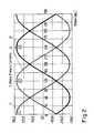
- FIG. 2a diagram showing alternating currents through the three-phases of the arrangement according to FIG. 1 as functions of time
- FIG. 3magnetic field lines of a magnetic field, which is produced by the conductor arrangement according to FIG. 1 , while a receiving device of a vehicle is located above the shown region of the conductor arrangement, wherein the direction of travel of the magnetic field distribution extends in the plane of the figure from right to left or from left to right,
- FIG. 4another diagram showing a region of the magnetic field which is produced by the conductor arrangement, while a load is connected to the receiving device in the vehicle,
- FIG. 5a diagram showing schematically the movement of the magnetic wave produced by the conductor arrangement along the track and showing the movement of the receiving device due to the movement of the vehicle on the track,
- FIG. 6a schematic circuit diagram of the conductor arrangement according to FIG. 1 which is connected to an AC voltage source via an electrical arrangement which is transforming a voltage of the source into a constant alternating current which is fed into the conductor arrangement,
- FIG. 7a circuit diagram showing a receiving device of a vehicle having coils for three different phases, wherein the receiving device is connected to an AC/DC-converter,
- FIG. 8a rail vehicle which is travelling on a track along which a conductor arrangement extends
- FIG. 9three consecutive points in time of a situation in which a rail vehicle travels on a track, wherein the track is provided with a plurality of consecutive line segments of a conductor arrangement, wherein the line segments can be switched on and off for providing the vehicle with energy,
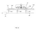
- FIG. 10an arrangement similar to the arrangement shown in FIG. 8 including a circuit diagram of a conductor arrangement along the track, wherein the conductor arrangement comprises line segments which can be switched on and off, and
- FIG. 11an arrangement similar to the arrangement shown in FIG. 1 , schematically illustrating a conductor arrangement between two rails of a railway.
- FIG. 1shows a conductor arrangement which may be located underground along a track, for example along the rails of a railway (see the arrangement shown in FIG. 11 , for example). In the latter case, the rails extend from left to right in the view of FIG. 1 .
- FIG. 1is understood to be a schematic view.
- the three lines 1 , 2 , 3 of the conductor arrangementcomprise sections which extend transversely to the direction of travel (from left to right or right to left). Only some of the transversely extending sections of lines 1 , 2 , 3 are denoted by the reference numerals, namely three sections 5 a , 5 b and 5 c of line 3 , some further sections of the line 3 by “5”, one section 5 x of line 2 and one section 5 y of line 1 .
- the arrangement 12 shown in FIG. 1is located underground of the track so that FIG. 1 shows a top view onto the arrangement 12 .
- the railsmay extend from left to right, at the top and the bottom in FIG. 1 , i.e. the transversely extending line sections may be completely within the boundaries defined by the rails (see also FIG. 11 ).
- the three lines 1 , 2 , 3may be connected to a three-phase AC current source.
- a positive current 11is flowing through line 3 .
- “Positive”means, that the current flows from the current source into the line.
- the three lines 1 , 2 , 3are connected at the other end of the arrangement together at a common star point 4 . Consequently, at least one of the other currents, here the current I 2 through the line 2 and the current I 3 through the line 1 , are negative.
- the star point ruleapplies which means that the sum of all currents flowing to and from the star point is zero at each point in time.
- the directions of the currents through lines 1 , 2 , 3are indicated by arrows.
- the sections of line 3 and the corresponding sections of lines 1 , 2 which extend transversely to the direction of travelpreferably have the same width and are parallel to each other. In practice, it is preferred there is no shift in width direction between the transversely extending sections of the three lines. Such a shift is shown in FIG. 1 for the reason that each section or each line can be identified.
- each linefollows the same serpentine-like path along the track, wherein the lines are shifted in the direction of travel by one third of the distance between consecutive sections of the same line extending transversely to the direction of travel.
- Tthe distance between consecutive sections 5
- This pattern of consecutive sections 5 , 5 x , 5 yrepeats at regular distances between these sections in the direction of travel.
- section 5 acarries a current from a first side A of the arrangement 12 to the opposite side B of the arrangement.
- Side Ais one side of the track (such as the right hand side in the direction of travel, when viewed from a travelling vehicle) and side B is the opposite side (e.g. the left side of the track), if the arrangement 12 is buried in the ground under the track, or more generally speaking, extends in a horizontal plane.
- the consecutive section 5 bconsequently carries an electric current at the same time which is flowing from side B to side A.
- the next consecutive section 5 c of line 3is consequently carrying a current from side A to side B. All these currents have the same size, since they are carried by the same line at the same time.
- the sections which extend transverselyare connected to each other by sections which extend in the direction of travel.
- the magnetic fields which are produced by sections 5 a , 5 b , 5 c , . . . of the line 3produce a row of successive magnetic poles of an electromagnetic field, wherein the successive magnetic poles (the poles produced by section 5 a , 5 b , 5 c , . . . ) have alternating magnetic polarities.
- the polarity of the magnetic pole which is produced by section 5 amay correspond at a specific point in time a magnetic dipole, for which the magnetic north pole is facing upwardly and the magnetic south pole is facing downwardly.
- the magnetic polarity of the magnetic field which is produced by section 5 bis oriented at the same time in such a manner that the corresponding magnetic dipole is facing with its south pole upwardly and with its north pole downwardly.
- the corresponding magnetic dipole of section 5 cis oriented in the same manner as for section 5 a and so on. The same applies to lines 1 and 2 .
- a conductor arrangement having only one phasemay be arranged as line 3 in FIG. 1 , but instead of the star point 4 , the end of the line 3 (which is located at the right hand side of FIG. 1 ) may be connected to the energy source (not shown in FIG. 1 ) by a connector line (not shown in FIG. 1 ) which extends along the track.
- a two-phase arrangementmay consist of lines 3 and 2 , for example, but the distance between the transversely extending sections of the two lines (or more generally speaking: of all lines) is preferably constant (i.e. the distances between a transversely extending section of line 3 to the two nearest transversely extending section of line 2 —in the direction of travel and in the opposite direction—are equal).
- FIG. 11is intended to illustrate some dimensions of the conductor arrangement, for example the conductor arrangement shown in FIG. 1 . Only parts of the three lines 111 , 112 , 113 are shown in FIG. 11 and connections to each other (e.g. via the star point 4 of FIG. 1 ) and to the power supply are omitted.
- the serpentine like lines 111 , 112 , 113are located between two rails 116 a , 116 b of a railway for railway vehicles (such as regional or local trains, such as a tram).
- the expression “between”is related to the top view shown in FIG. 11 .
- the lines 111 , 112 , 113may be located below the level of the rails 116 .
- Each of the lines 111 , 112 , 113comprises linear sections which extend transversely to the direction of the track, i.e. the longitudinal direction of the rails 116 .
- These transversely extending sectionsare connected to the consecutive transversely extending sections of the same line via longitudinally extending sections, which extend in the longitudinal direction of the rails.
- the transversely and linearly extending sectionshave a length LB, which is preferably at least as large as half the distance RB between the rails.
- the distance RBmay be 1 m and the length of the transversely extending sections may be 50 cm or in the range of 50 to 75 cm.
- the transversely extending sections and the longitudinally extending sections of the same lineare connected to each other by curved sections.
- the curvaturecorresponds, for example, to the curvature of a circle having a radius of 150 mm.
- FIG. 11also schematically shows a shaded area 118 which is covered by a coil of a receiving device of a vehicle travelling on the rails 116 .
- the width of the coilis equal to the lengths of the transversely extending sections of the lines. However, in practice, it is preferred that this width is smaller than the length of the transversely extending sections. This allows for a shift in the position of the coil in the direction transverse to the travel direction, as indicated by two arrows and a line below the shaded area 118 . Such a shift would not influence the reception of energy by the coil, if the shift would not move the coil beyond the boundaries of the transversely extending sections.
- the currents through the phases 1 , 2 , 3 of FIG. 1are phase currents of a conventional three-phase alternating current.
- L 1 , L 2 , L 3 in FIG. 2denote that the serpentine like lines 1 , 2 , 3 form inductivities.
- the peak current value of the currentsmay be in the range of 300 A respectively ⁇ 300 A. However, greater or smaller peak currents are also possible. 300 A peak current is sufficient to provide propulsion energy to a tram for moving the tram along a track of some hundred meters to a few kilometres, for example within the historic town centre of a city.
- the trammay withdraw energy from an on-board energy storage, such as a conventional electrochemical battery arrangement and/or a super cap arrangement. The energy storage may be charged again fully, as soon as the tram has left the town centre and is connected to an overhead line.
- FIG. 3depicts the situations at four different points in time which correspond to “0”, “30”, “60”, “90” on the time scale of FIG. 2 .
- the time scale of FIG. 2can also be interpreted as a scale showing the angle of the sinusoidal behaviour of the currents, which means that FIG. 2 shows the behaviour of the currents over one full period, i.e. the current values at the beginning of the period at “0” are the same as at the end of the period at “360”.
- transversely extending sections of lines 1 , 2 , 3are shown in the left of the four partial diagrams of FIG. 3 .
- Reference sign “I 1 ”denotes the current I 1 which is flowing through a transversely extending section of line 1 and so on.
- These transversely extending sectionsextend perpendicularly to the image plane of FIG. 3 , wherein the image plane is a vertical cut plane through the arrangement 12 of FIG. 1 , wherein the image planes of FIG. 1 and FIG. 3 are perpendicular to each other and wherein the image plane of FIG. 3 extends in the direction of travel, cutting the sections 5 of FIG. 1 in two halves.
- electromagnetic coils 7are schematically shown as flat rectangularly framed areas.
- ferromagnetic backbones 8are located in order to bundle and divert the magnetic field lines. These backbones 8 have the functions of a core of an electromagnet.
- FIG. 4shows a similar view as the views shown in FIG. 3 .
- the figureis meant to illustrate the hypothetical situation that coils in the vehicle (which is travelling on the track) induce current in the conductor arrangement of the track.
- FIG. 4also shows cross sections through electric conductors 41 a , 41 b in the regions 7 a , 7 b , 7 c , 7 d of the coil 7 .
- region 7 a , 7 ba current which is oriented upwardly out of the image plane of FIG. 4 is flowing at the depicted point in time.
- the currentis directed downwardly into the image plane of FIG.
- the electromagnetic field(illustrated by the field lines in FIG. 4 ) which is produced by the coil 7 , is symmetric to the border line of sections 7 b and 7 d , since the amounts of the currents in sections 7 a to 7 d are also symmetric to the border line.
- FIG. 5shows another cut along a cutting plane which extends vertically and which extends in the travel direction.
- the wires or bundles of wires of lines 1 , 3 , 2which are located in sections of the lines 1 , 3 , 2 which extend transversely to the direction of travel are shown in the upper half of FIG. 5 .
- seven sections of the arrangement 12 which extend transversely to the travel directionare shown in FIG. 5 , at least partially.
- the first, fourth and seventh section in the row(from left to right) belong to line 1 . Since the direction of the current I 1 through section 5 b (the fourth section in FIG. 5 ) is opposite to the direction of the current I 1 through the sections 5 a , 5 c (the first and the seventh section in FIG.
- the produced electromagnetic waveis moving in the direction of travel at a speed vw.
- the waveis denoted by 9 , the inductivity of the arrangement 12 by Lp.
- FIG. 5shows a line segment of arrangement 12 , the length of which is equal to twice the distance between three consecutive transversely extending sections of a line, here line 1 .
- the arrangement shown in FIG. 6comprises a conductor arrangement 103 , 104 , 105 , which may be the conductor arrangement 12 according to FIG. 1 .
- the three-phase system 103 , 104 , 105carries phase currents I 1 , I 2 ,I 3 in phases 1 , 2 , 3 .
- the inherent inductivities of the phases 1 , 2 , 3are denoted by Lp 1 , Lp 2 , Lp 3 which produce the electromagnetic field for transferring energy to any vehicle on the track.
- the lines 1 , 2 , 3also comprise leakage inductivities Ls 1 , Ls 2 , Ls 3 , as indicated in block 104 in FIG. 6 .
- the impedance of these undesired leakage inductivitiesis compensated by capacities Ck 1 , Ck 2 , Ck 3 in the lines 1 , 2 , 3 as shown in block 103 .
- the electric energy which is used to produce the electromagnetic fields in lines 1 , 2 , 3is generated by a three-phase voltage source 101 .
- the phase sources for the phasesare denoted by V 1 , V 2 , V 3 in block 101 .
- the produced voltages in the lines 1 , 2 , 3are denoted by U 1 , U 2 , U 3 .
- the voltage sourceis connected to the input of a constant-current source 102 .
- An output of this source 102is connected to the capacities in block 103 .
- the currents I 1 , I 2 , I 3are generated. These currents are constant over time, independently of the energy which is transferred from lines 1 , 2 , 3 to any vehicle on the track.
- each line 1 , 2 , 3comprises in each line 1 , 2 , 3 an input inductivity L 1 a , L 2 a , L 3 a .
- each line 1 , 2 , 3comprises an output inductivity L 1 b , L 2 b , L 3 b .
- each line 1 , 2 , 3is connected to a common star point 61 via a capacity C 1 , C 2 , C 3 .
- FIG. 7shows a circuit diagram of an arrangement which may be located in a vehicle which is travelling on the track.
- the arrangementcomprises a three-phase receiving device for receiving the electromagnetic field from the track and for producing electric energy therefrom.
- the receiving devicecomprises one coil or an arrangement of coils for each phase la, 2 a , 3 a , wherein the coils are denoted by L 71 , L 72 , L 73 (block 201 ).
- the phases 1 a , 2 a , 3 aare connected together at a common star point 71 .
- Leakage inductivities (not separately shown in FIG. 7 ) of the phases 1 a , 2 a , 3 aare compensated by capacities C 71 , C 72 , C 73 , as shown in block 202 .
- the output side of the receiving device 201 , 202where the phase currents Is 1 a , Is 2 a , Is 3 a are shown in FIG. 7 is connected to an AC/DC (alternating current/direct current) converter 203 .
- the DC-side of the converter 203is connected to lines 76 a , 76 b of an intermediate circuit.
- the lines 76 a , 76 bare connected to each other via a smoothing capacity C 7 d as indicated by “ 204 ”.
- the electric loadwhich may be provided with energy within the vehicle is denoted by a resistance RL at “ 205 ” which may be connected to the lines 76 a , 76 b of the intermediate circuit.
- “Ud”indicates that the load RL may cause a voltage drop, wherein Ud is the voltage in the intermediate circuit for example.
- FIG. 8shows a track 83 (here: a railway track having two rails) which is occupied by a track bound vehicle 81 , such as a regional public transport train or a tram.
- a track bound vehicle 81such as a regional public transport train or a tram.
- the arrangement showncomprises an electric conductor arrangement for producing an electromagnetic field, thereby transferring energy to the vehicle on the track.
- the conductor arrangement 89is shown schematically.
- the conductor arrangementmay be designed as shown in FIG. 1 .
- the conductor arrangement 89(and this applies to other arrangements, not only to the example shown in FIG. 8 ) may be located underground or above ground.
- the conductor arrangementmay be located above ground between the rails on the level of a railway sleeper, or partly above ground, but under the railway sleepers.
- the sleepersare made of concrete for example, the sleepers or the other construction for holding the rails may comprise holes and/or cavities, through which the line or lines of the conductor arrangement extends. Thereby, the railway construction may be used to hold the line(s) in the desired serpentine shape.
- the track bound vehicle 81comprises at its underside a receiving device 85 for receiving the electromagnetic field which is produced by the conductor arrangement 89 .
- the receiving device 85is electrically connected to an on-board electric network 86 so that the electric energy, which is induced in the receiving device 85 may be distributed within the vehicle 81 .
- auxiliary devices 90 and propulsion units 80 , 84 for driving propulsion motors (not shown) in bogies 780 a , 780 b having wheels 88 a , 88 b , 88 c , 88 dmay be connected to the distribution network 86 .
- an energy storage 82such as an electrochemical energy storage or an arrangement of capacitors, such as super caps, may also be connected to the distribution network.
- the energy storage 82may be charged by the energy received by the receiving device, in particular during stops of the vehicle 81 on the track.
- a part of the propulsion energy which is needed to move the vehicle 81may be withdrawn from the energy storage 82 and at the same time the energy, which is received by the receiving device may contribute to the propulsion, i.e. may be part of the propulsion energy.
- FIG. 9illustrates the concept of a conductor arrangement 112 comprising sections which can be switched on and off so that only sections, which are switched on produce an electromagnetic field in order to transfer energy to the vehicle or vehicles on the track.
- the example of FIG. 9shows 5 segments T 1 , T 2 , T 3 , T 4 , T 5 which are arranged in a row of successive segments along the track.
- a vehicle 92such as a tram, is travelling on the track. Under floor of the vehicle 92 two receiving devices 95 a , 95 b for receiving electromagnetic field produced by the segments are provided.
- the receiving devices 95 a , 95 bmay be redundant devices, wherein just one of the devices is necessary for operating the vehicle. This increases operation safety.
- the devices 95 a , 95 bmay also be non-redundant devices which may produce energy at the same time for operating the vehicle. However, it may happen in this case, that at least one of the devices 95 may not produce electric energy.
- the vehiclemay comprise more receiving devices.
- the following descriptionrelates to all these cases and, in addition, to the case that the vehicle has just one receiving device.
- the vehicleis moving from the left to the right.
- the vehicle 92occupies the track above elements T 2 , T 3 and partly occupies the track above elements T 1 and T 4 .
- the receiving devices 95 or the receiving deviceare located always above elements which are fully occupied by the vehicle. This is the case, because the distance between the receiving devices to the nearest end of the vehicle in lengthwise direction is greater than the length of each segment of the conductor arrangement 112 .
- FIG. 10shows an arrangement which is similar to the arrangement shown in FIG. 9 . In fact, it may be a different view of the same arrangement as shown in FIG. 9 . However, FIG. 10 shows additional parts of the arrangement.
- Each of the successive segments 103 a , 103 b , 103 c of the conductor arrangement for producing an electromagnetic fieldis connected via a separate switch 102 a , 102 b , 102 c for switching on and off the element 103 , to a mainline 108 .
- the mainline 108may comprise wires or cables for each phase.
- the far end of the mainline 108(at the right hand side of FIG. 10 , but not shown) may comprise a common star point of all three-phases.
- On the opposite site of the mainline 108it is connected to an energy source 101 , such as the arrangement according to blocks 101 , 102 as shown in FIG. 6 .
Landscapes
- Engineering & Computer Science (AREA)
- Power Engineering (AREA)
- Mechanical Engineering (AREA)
- Transportation (AREA)
- Life Sciences & Earth Sciences (AREA)
- Sustainable Development (AREA)
- Sustainable Energy (AREA)
- Computer Networks & Wireless Communication (AREA)
- Current-Collector Devices For Electrically Propelled Vehicles (AREA)
- Electric Propulsion And Braking For Vehicles (AREA)
Abstract
Description
- the system comprises an electric conductor arrangement for producing an electromagnetic field and for thereby transferring the energy to the vehicle,
- the electric conductor arrangement comprises at least one line for carrying one phase of an alternating current,
- the line extends along the track,
- the line is arranged in such a manner that it produces—at each point in time while the alternating electric current is flowing through the line—a row of successive magnetic poles of an electromagnetic field, wherein the successive magnetic poles have alternating magnetic polarities,
- the row of successive magnetic poles extends in the travel direction of the vehicle which is defined by the track.
- the system comprises an electric conductor arrangement
- the electric conductor arrangement comprises at least one line for carrying one phase of an alternating current,
- the line extends along the track,
- the line comprises a plurality of sections which extend transversely to the travel direction of the vehicle which is defined by the track,
- the sections of the same line are arranged in a row along the track in such a manner that—at each point in time while an alternating electric current is flowing through the line—the alternating current flows through successive sections in the row alternatingly in opposite directions
- an electromagnetic field is produced by an electric conductor arrangement located along the track thereby transferring the energy to the vehicle,
- the electromagnetic field is produced by conducting at least the phase current of one phase of an alternating current in a line of the electric conductor arrangement,
- the phase current is conducted along the track in the line in such a manner that—at each point in time while the phase current is flowing through the line—it flows transversely to the travel direction of the vehicle through a plurality of sections of the line, wherein it flows through a first group of the sections in a first direction and it flows through a second group of the sections in the opposite direction and wherein the sections of the first group and of the second group alternate in the direction of travel.
Claims (17)
Applications Claiming Priority (3)
| Application Number | Priority Date | Filing Date | Title |
|---|---|---|---|
| GB0812345.7 | 2008-07-04 | ||
| GB0812345AGB2461578A (en) | 2008-07-04 | 2008-07-04 | Transferring electric energy to a vehicle |
| PCT/EP2009/004960WO2010000494A1 (en) | 2008-07-04 | 2009-07-02 | Transferring electric energy to a vehicle |
Publications (2)
| Publication Number | Publication Date |
|---|---|
| US20110198176A1 US20110198176A1 (en) | 2011-08-18 |
| US8590682B2true US8590682B2 (en) | 2013-11-26 |
Family
ID=39718044
Family Applications (1)
| Application Number | Title | Priority Date | Filing Date |
|---|---|---|---|
| US13/001,837Active2030-06-14US8590682B2 (en) | 2008-07-04 | 2009-07-02 | Transferring electric energy to a vehicle |
Country Status (15)
| Country | Link |
|---|---|
| US (1) | US8590682B2 (en) |
| EP (1) | EP2310224B1 (en) |
| KR (2) | KR101757134B1 (en) |
| CN (1) | CN102083649B (en) |
| AU (1) | AU2009265943B2 (en) |
| BR (1) | BRPI0914214A2 (en) |
| CA (1) | CA2729890C (en) |
| DK (1) | DK2310224T3 (en) |
| ES (1) | ES2579212T3 (en) |
| GB (1) | GB2461578A (en) |
| IL (1) | IL210255A0 (en) |
| MX (1) | MX2010014398A (en) |
| RU (1) | RU2481968C2 (en) |
| TW (1) | TW201008805A (en) |
| WO (1) | WO2010000494A1 (en) |
Cited By (6)
| Publication number | Priority date | Publication date | Assignee | Title |
|---|---|---|---|---|
| US20120318624A1 (en)* | 2010-02-23 | 2012-12-20 | Bombardier Transportation Gmbh | Detecting the presence of a vehicle |
| US20130248311A1 (en)* | 2010-11-22 | 2013-09-26 | Bombardier Transportation Gmbh | Transferring electric energy to a vehicle by induction |
| US20140182991A1 (en)* | 2012-12-27 | 2014-07-03 | Alstom Transport Sa | Method for optimizing the operation of a reversible traction substation and associated devices |
| US20170217315A1 (en)* | 2014-09-29 | 2017-08-03 | Bombardier Primove Gmbh | Method of and Control System for Operating a Circuit Arrangement |
| US10510482B2 (en) | 2015-06-26 | 2019-12-17 | Bombardier Primove Gmbh | Primary sided-arrangement of primary winding structures, a method of manufacturing the primary-sided arrangement, a system for inductive power transfer and a method for inductively supplying power to a vehicle |
| US11651891B2 (en)* | 2009-08-07 | 2023-05-16 | Auckland Uniservices Limited | Roadway powered electric vehicle system |
Families Citing this family (25)
| Publication number | Priority date | Publication date | Assignee | Title |
|---|---|---|---|---|
| GB2461577A (en)* | 2008-07-04 | 2010-01-06 | Bombardier Transp Gmbh | System and method for transferring electric energy to a vehicle |
| GB2477080A (en)* | 2009-12-21 | 2011-07-27 | Bombardier Transp Gmbh | Modular track for vehicle using inductive energy transfer |
| KR101221486B1 (en)* | 2010-06-03 | 2013-01-14 | 한국과학기술원 | Space division multiplexed power supply and collector device |
| FR2965758B1 (en) | 2010-10-07 | 2014-12-26 | Alstom Transport Sa | GROUND FEEDING SYSTEM FOR TRANSPORT VEHICLE AND ASSOCIATED METHODS. |
| GB2485616A (en)* | 2010-11-22 | 2012-05-23 | Bombardier Transp Gmbh | Route for transferring electric energy to vehicles |
| EP2524834A1 (en) | 2011-05-18 | 2012-11-21 | Brusa Elektronik AG | Device for inductive charging of at least one electrical energy storage device of an electric car |
| GB2491651A (en) | 2011-06-10 | 2012-12-12 | Bombardier Transp Gmbh | System and Method for Transferring Electric Energy to a Vehicle Using Constant Current Operation of Segments of a Conductor Arrangement at resonance frequency |
| GB2491652A (en)* | 2011-06-10 | 2012-12-12 | Bombardier Transp Gmbh | System and Method for Transferring Electric Energy to a Vehicle Using a Plurality of Segments of a Conductor Arrangement |
| JP5803475B2 (en)* | 2011-09-16 | 2015-11-04 | 株式会社Ihi | Mobile vehicle power supply system |
| GB2496433A (en)* | 2011-11-10 | 2013-05-15 | Bombardier Transp Gmbh | Inductively transferring energy to an electric vehicle |
| GB2496436A (en)* | 2011-11-10 | 2013-05-15 | Bombardier Transp Gmbh | Inductively transferring energy to an electric vehicle |
| DE102011119259A1 (en)* | 2011-11-24 | 2013-05-29 | Bombardier Transportation Gmbh | Doppler rectifier for multiphase contactless power transmission system |
| GB201121938D0 (en)* | 2011-12-21 | 2012-02-01 | Dames Andrew N | Supply of grid power to moving vehicles |
| DE102012107358B4 (en) | 2012-08-10 | 2025-04-17 | Industrieanlagen-Betriebsgesellschaft Mbh | Primary conductor system and power supply device |
| GB2507741A (en) | 2012-11-07 | 2014-05-14 | Bombardier Transp Gmbh | Cable bearing element for inductive power coupling |
| KR20150085827A (en)* | 2012-11-12 | 2015-07-24 | 오클랜드 유니서비시즈 리미티드 | Vehicle or moving object detection |
| JP5716725B2 (en)* | 2012-11-21 | 2015-05-13 | トヨタ自動車株式会社 | Power transmission device and power transmission system |
| GB2508924A (en)* | 2012-12-17 | 2014-06-18 | Bombardier Transp Gmbh | Inductive power transfer system having array of sensing capacitors |
| KR101481015B1 (en)* | 2013-06-25 | 2015-01-15 | 한국에너지기술연구원 | System for managing transportation power and method for managing transportation power using the same |
| DE102014109944A1 (en)* | 2014-07-16 | 2016-01-21 | Paul Vahle Gmbh & Co. Kg | Inductive energy transfer system with multi-phase primary circuit |
| US9698608B2 (en)* | 2014-12-29 | 2017-07-04 | Qualcomm Incorporated | System and method for multi-coil dual backbone dynamic inductive power transfer |
| JP6677523B2 (en)* | 2016-02-17 | 2020-04-08 | 株式会社Fuji | Wireless power supply |
| RU2759774C1 (en)* | 2021-07-22 | 2021-11-17 | Частное Учреждение Музей "Царь-Макет Страны" | Power supply system for the vehicles of a scale model |
| US12024045B1 (en) | 2023-03-16 | 2024-07-02 | Gideon Eden | System for fast battery charging |
| US11949278B1 (en) | 2023-03-16 | 2024-04-02 | Gideon Eden | Fast-charging battery |
Citations (110)
| Publication number | Priority date | Publication date | Assignee | Title |
|---|---|---|---|---|
| GB638143A (en) | 1945-06-27 | 1950-05-31 | Standard Telephones Cables Ltd | Directive antenna arrangements, particularly for use in radio direction finders |
| US2518736A (en) | 1946-08-27 | 1950-08-15 | Hazeltine Research Inc | Directive loop antenna |
| GB657035A (en) | 1946-03-26 | 1951-09-12 | George Iljitch Babat | High frequency electric transport system with contactless transmission of energy |
| GB657036A (en) | 1946-03-26 | 1951-09-12 | George Iljitch Babat | Overhead and underground traction power supply systems for high-frequency electrified transport with contactless energy transfer |
| US3225351A (en) | 1962-03-09 | 1965-12-21 | Maurice G Chatelain | Vertically polarized microstrip antenna for glide path system |
| DE1806977A1 (en) | 1967-11-17 | 1969-06-19 | Merlin Gerin | Vehicle with a linear electric motor |
| GB1280148A (en) | 1968-10-16 | 1972-07-05 | Tracked Hovercraft Ltd | Linear motor propelled air cushion vehicle |
| DE2310812A1 (en) | 1972-03-08 | 1973-09-20 | Hitachi Ltd | POWER SUPPLY SYSTEM FOR LINEAR MOTOR |
| US3863574A (en) | 1973-02-08 | 1975-02-04 | Siemens Ag | Power supply for high speed vehicles |
| GB1390225A (en) | 1972-06-14 | 1975-04-09 | British Railways Board | Vehicle control system |
| US3914562A (en) | 1971-05-24 | 1975-10-21 | John G Bolger | Supplying power to vehicles |
| US4328499A (en) | 1979-10-24 | 1982-05-04 | The Marconi Company Limited | Radio direction finding systems |
| US4331225A (en) | 1978-04-25 | 1982-05-25 | Bolger John G | Power control system for electrically driven vehicle |
| EP0187527A2 (en) | 1985-01-04 | 1986-07-16 | U T D C Inc. | Lim secondary reactance compensation and thrust control |
| EP0187526A2 (en) | 1985-01-04 | 1986-07-16 | U T D C Inc. | Contactless powering of lim vehicle electrical system by recovery of lim slip power |
| DE3527309A1 (en) | 1985-07-26 | 1987-02-05 | Licentia Gmbh | Power supply system for railways, in particular short-distance traffic railways whose overhead contact lines/current rails are supplied with direct current |
| DE3714263A1 (en) | 1987-04-29 | 1988-10-20 | Goetting Hans Heinrich Jun | Arrangement for position-line or location determination of passive code or information carriers with respect to the identification device (identifying device) |
| EP0289868A2 (en) | 1987-05-08 | 1988-11-09 | Inductran Corporation | Roadway power and control system for inductively coupled trans portation system |
| WO1991001232A1 (en) | 1989-07-20 | 1991-02-07 | Musachio Nicholas R | Electrical vehicle transportation system |
| GB2236957A (en) | 1989-10-20 | 1991-04-24 | Artin Ind Co Ltd | Toy vehicle track |
| WO1992017929A1 (en) | 1991-03-26 | 1992-10-15 | Piper, James, William | Inductive power distribution system |
| DE4115568A1 (en) | 1991-05-13 | 1993-02-04 | German Gresser | Futuristic electric vehicle - uses inductive pick=up from cable buried in street surface through tyres or subframe and homopolar motor |
| WO1993023909A1 (en) | 1992-05-10 | 1993-11-25 | Auckland Uniservices Limited | A primary inductive pathway |
| WO1993023908A1 (en) | 1992-05-10 | 1993-11-25 | Auckland Uniservices Limited | A non-contact power distribution system |
| DE4236340A1 (en) | 1992-10-28 | 1994-05-05 | Daimler Benz Ag | Arrangement for individual contactless energy transfer to moving consumers |
| US5311973A (en) | 1992-07-31 | 1994-05-17 | Ling-Yuan Tseng | Inductive charging of a moving electric vehicle's battery |
| WO1994025304A1 (en) | 1993-05-03 | 1994-11-10 | Cadac Holdings Limited | Power collector for inductive power transfer |
| WO1995011545A1 (en) | 1993-10-21 | 1995-04-27 | Auckland Uniservices Limited | Inductive power pick-up coils |
| DE4342319A1 (en) | 1993-12-11 | 1995-06-14 | Fritz Keller | Route control system for automatically steered vehicles |
| WO1995030556A2 (en) | 1994-05-05 | 1995-11-16 | H.R. Ross Industries, Inc. | Roadway-powered electric vehicle having on-board energy storage means and information means |
| DE4429656C1 (en) | 1994-08-20 | 1996-04-25 | Juergen Prof Dr Ing Meins | Device for contactless transfer of electrical power to a moving objects such as cranes, lifts and traffic systems. |
| DE4446779A1 (en) | 1994-12-24 | 1996-06-27 | Daimler Benz Ag | Arrangement for the contactless inductive transmission of electrical power |
| DE19512523A1 (en) | 1995-04-03 | 1996-10-10 | Daimler Benz Ag | Track-guided transport system for goods conveying |
| EP0761493A1 (en) | 1995-08-22 | 1997-03-12 | ANSALDO TRASPORTI S.p.A. | Supply line for an electric vehicle and transport system using it |
| US5669470A (en) | 1994-05-05 | 1997-09-23 | H. R. Ross Industries, Inc. | Roadway-powered electric vehicle system |
| US5708427A (en) | 1996-04-18 | 1998-01-13 | Bush; E. William | Vehicle in-lane positional indication/control by phase detection of RF signals induced in completely-passive resonant-loop circuits buried along a road lane |
| WO1998023017A1 (en) | 1996-11-20 | 1998-05-28 | N.R. Development Limited | Container for housing heat generating equipment |
| US5821728A (en) | 1996-07-22 | 1998-10-13 | Schwind; John P. | Armature induction charging of moving electric vehicle batteries |
| EP0608242B1 (en) | 1991-08-09 | 1998-11-18 | Gründl Und Hoffmann Gesellschaft Für Elektrotechnische Entwicklungen Mbh | Synchronous linear drive with electromagnetic energy transfer |
| DE19735624C1 (en) | 1997-08-18 | 1998-12-10 | Daimler Benz Ag | Method of inductive transfer of electrical power to several moving loads |
| EP0681939B1 (en) | 1994-05-10 | 1999-01-07 | Bernard Saugy | Electrical transport installation |
| DE19723959A1 (en) | 1997-06-06 | 1999-01-21 | Siemens Ag | Driving system for a magnetic levitation vehicle |
| WO1999008359A1 (en) | 1997-08-08 | 1999-02-18 | Meins Jurgen G | Method and apparatus for supplying contactless power |
| DE19746919A1 (en) | 1997-10-24 | 1999-05-06 | Daimler Chrysler Ag | Electrical transmission device |
| DE19801586A1 (en) | 1998-01-19 | 1999-07-22 | Daimler Chrysler Ag | Arrangement for operating transport system with rail-guided magnetically suspended vehicle |
| EP0962353A1 (en) | 1998-06-04 | 1999-12-08 | Alstom Entreprise SA | Ground feeding system for electrical vehicle and associated vehicle |
| EP1011187A1 (en) | 1998-12-10 | 2000-06-21 | Paul Vahle GmbH & Co. KG | Device for non-contact, inductive transmission of energy |
| US6089512A (en) | 1995-04-03 | 2000-07-18 | Daimler-Benz Aktiengesellschaft | Track-guided transport system with power and data transmission |
| US6089362A (en) | 1996-09-05 | 2000-07-18 | Kabushiki Kaisha Toyoda Jidoshokki Seisakusho | Non-contact power supply device and method for conveyor carriage |
| DE20002984U1 (en) | 1999-10-01 | 2000-07-20 | Rofa Rosenheimer Förderanlagen GmbH, 83059 Kolbermoor | Underfloor rail system for industrial trucks with contactless inductive power supply |
| EP1043187A1 (en) | 1999-04-07 | 2000-10-11 | Société Générale de Techniques et d'Etudes | Device for detecting the presence of a vehicle with an improved reliability |
| EP1043186A1 (en) | 1999-04-07 | 2000-10-11 | Société Générale de Techniques et d'Etudes | Ground power supply assembly for electric vehicle |
| WO2001018936A1 (en) | 1999-09-09 | 2001-03-15 | Auckland Uniservices Limited | Control of series-resonant inductive pickups |
| EP1095812A1 (en) | 1999-10-25 | 2001-05-02 | Alstom | Floor supply system for an electrical vehicle and electrical vehicle to be fed by such a supply system |
| US6250442B1 (en) | 1997-04-30 | 2001-06-26 | Societe Generale De Techniques Et D'etudes | Ground power supply for electric vehicle with earth connection |
| WO2001071882A1 (en) | 2000-03-22 | 2001-09-27 | Lju Industrieelektronik Gmbh | Electric suspended conveyor with contactless energy transmission |
| DE10013767A1 (en) | 2000-03-20 | 2001-10-11 | Rosenheimer Foerderanlage | Electric transport vehicles surface transport system with supply-and control-system for contactless power transmission, has flush-mounted rail system for track-guidance and contactless inductive power supply |
| WO2002035676A1 (en) | 2000-10-27 | 2002-05-02 | Sew-Eurodrive Gmbh & Co | Method and device for non-contact energy transmission |
| US6421600B1 (en)* | 1994-05-05 | 2002-07-16 | H. R. Ross Industries, Inc. | Roadway-powered electric vehicle system having automatic guidance and demand-based dispatch features |
| DE10026175A1 (en) | 2000-04-18 | 2002-07-25 | Schleifring Und Appbau Gmbh | Arrangement for contactless transfer of electrical signals/energy between mobile units has external units coupled to common bus structure by capacitive element(s) |
| DE10112892A1 (en) | 2001-03-15 | 2002-10-10 | Vahle Paul Kg | Device for transferring data in system for contactless inductive energy transfer uses primary current conductor with inductive coupling in and out of data to transfer data in addition to energy |
| US6499701B1 (en) | 1999-07-02 | 2002-12-31 | Magnemotion, Inc. | System for inductive transfer of power, communication and position sensing to a guideway-operated vehicle |
| US20030105560A1 (en) | 2001-12-04 | 2003-06-05 | Yoichi Sugita | Train control method and apparatus |
| WO2003052900A2 (en) | 2001-12-18 | 2003-06-26 | Otis Elevator Company | Hybrid linear motor driven transportation system |
| DE20209092U1 (en) | 2002-06-12 | 2003-10-16 | Wampfler Aktiengesellschaft, 79576 Weil am Rhein | Primary conductor arrangement for a system for the inductive transmission of electrical energy |
| DE10227253A1 (en) | 2002-04-10 | 2003-10-23 | Transrapid Int Gmbh & Co Kg | Device for operating a magnetic vehicle |
| WO2003095282A2 (en) | 2002-05-07 | 2003-11-20 | Magtube, Inc | Magnetically levitated transportation system and method |
| DE10225005C1 (en) | 2002-06-06 | 2003-12-04 | Wampfler Ag | Inductive energy transmission device for moving load with inductive coupling used for energy transfer between successive conductor path sections |
| WO2004030975A2 (en) | 2002-10-01 | 2004-04-15 | Magnemotion, Inc. | Suspending, guiding and propelling vehicles using magnetic forces |
| US6753666B2 (en) | 2002-04-10 | 2004-06-22 | Robert Bosch Gmbh | Apparatus for operating a magnet vehicle |
| GB2399465A (en) | 2003-03-13 | 2004-09-15 | Bombardier Transp | A protection arrangement for transferring electric power to a power consumer |
| WO2004105226A1 (en) | 2003-05-23 | 2004-12-02 | Auckland Uniservices Limited | Frequency controlled resonant converter |
| DE10326614A1 (en) | 2003-06-13 | 2004-12-30 | Dürr Automotion Gmbh | transport system |
| DE10334736A1 (en) | 2003-07-29 | 2005-02-17 | Rexroth Indramat Gmbh | Linear motor with advancement or motion regulation for use in industrial automated processes, with bearing unit for guiding a secondary component along the desired path |
| DE10334737A1 (en) | 2003-07-29 | 2005-02-24 | Rexroth Indramat Gmbh | Linear motor for non-contact power supply to moving consumers/modular conveying devices in automated industrial processes has a power transfer interface and field-generating coils |
| US6868073B1 (en) | 2000-06-06 | 2005-03-15 | Battelle Memorial Institute K1-53 | Distance/ranging by determination of RF phase delta |
| DE10346105A1 (en) | 2003-10-04 | 2005-04-21 | Nexans | Method of constructing a track for magnetic monorail train, involves fitting the winding cables to each section of carrier with complementary parts of plug connection |
| DE10349242B3 (en) | 2003-10-20 | 2005-04-21 | Sew-Eurodrive Gmbh & Co. Kg | Contactless electrical coupling system for load current and data involves electrical wire carrying medium frequency AC and synchronization pulses and inductive coupling circuit in movable equipment |
| US20050161300A1 (en) | 2002-06-12 | 2005-07-28 | Wampfler Aktiengesellschaft | Primary conductor arrangement for a system for the inductive transmission of electrical energy |
| DE102004009896A1 (en) | 2004-02-26 | 2005-09-15 | Paul Vahle Gmbh & Co. Kg | Inductive contactless energy transmission system primary line has compensating capacitance formed by double length coaxial conductors |
| EP1582395A1 (en) | 2004-02-02 | 2005-10-05 | ROFA Rosenheimer Förderanlagen GmbH | Transport system with inductive energy transfer |
| DE102004012746A1 (en) | 2004-03-15 | 2005-10-06 | Thyssenkrupp Transrapid Gmbh | Magnet arrangement for a magnetic levitation vehicle |
| EP1610450A2 (en) | 2004-06-16 | 2005-12-28 | Hitachi, Ltd. | Power converter system for railway vehicles |
| US6985107B2 (en) | 2003-07-09 | 2006-01-10 | Lotek Wireless, Inc. | Random antenna array interferometer for radio location |
| US7038573B2 (en) | 2003-09-08 | 2006-05-02 | Single Chip Systems Corporation | Systems and methods for tracking the location of items within a controlled area |
| DE10216422B4 (en) | 2002-04-12 | 2006-07-06 | Wampfler Aktiengesellschaft | Device for inductive power supply and guidance of a moving object |
| US7084527B2 (en) | 2000-03-22 | 2006-08-01 | Lju Industrieelektronik Gmbh | Electric suspended conveyor with contactless energy transmission |
| US20060197939A1 (en) | 2005-03-07 | 2006-09-07 | Schweizerische Bundesbahnen Sbb | Identification system and method of determining motion information |
| DE69929353T2 (en) | 1999-10-29 | 2006-09-14 | Centre d'Innovation sur le Transport d'Energie du Quebec, Verennes | EARTH-COOLED DISTRIBUTION EQUIPMENT AND METHOD |
| DE102006006384A1 (en) | 2005-03-02 | 2006-09-21 | Sew-Eurodrive Gmbh & Co. Kg | Contactless energy transmission system for use between drive mechanism and rail system, has elongated sections attached to normally open contact and break contact unit, which short-circuits sections, where open contact isolates sections |
| EP1744443A1 (en) | 2004-03-30 | 2007-01-17 | Daifuku Co., Ltd. | Noncontact power supply facility |
| DE102004031580B4 (en) | 2004-06-29 | 2007-02-01 | Sew-Eurodrive Gmbh & Co. Kg | Arrangement for non-contact inductive energy transmission to movable devices |
| DE19512107B4 (en) | 1995-04-03 | 2007-06-28 | Daimlerchrysler Ag | Track-guided transport system with contactless energy transfer |
| DE102006049588A1 (en) | 2006-02-03 | 2007-08-16 | Sew-Eurodrive Gmbh & Co. Kg | transport system |
| US7277675B2 (en) | 2000-04-18 | 2007-10-02 | Schleifring Und Apparatebau Gmbh | Array for the contact-less transmission of electrical signals or energy |
| WO2007126321A1 (en) | 2006-05-02 | 2007-11-08 | Auckland Uniservices Limited | Pick-up apparatus for inductive power transfer systems |
| US7298314B2 (en) | 2002-08-19 | 2007-11-20 | Q-Track Corporation | Near field electromagnetic positioning system and method |
| US7365698B2 (en) | 2005-08-19 | 2008-04-29 | Rf Industries Pty Ltd | Dipole antenna |
| US20080129246A1 (en) | 2006-11-10 | 2008-06-05 | Mitsubishi Heavy Industries, Ltd. | Non-contact type power feeder system for mobile object and protecting apparatus thereof |
| US20080316103A1 (en) | 2007-06-22 | 2008-12-25 | Broadcom Corporation | Apparatus for position detection using multiple antennas |
| WO2009007666A1 (en) | 2007-07-10 | 2009-01-15 | Redcliffe Magtronics Ltd | Automatic vehicle guidance protection system |
| US7518520B2 (en) | 2005-08-02 | 2009-04-14 | International Business Machines Corporation | RFID reader having antenna with directional attenuation panels for determining RFID tag location |
| US7560927B2 (en) | 2003-08-28 | 2009-07-14 | Massachusetts Institute Of Technology | Slitted and stubbed microstrips for high sensitivity, near-field electromagnetic detection of small samples and fields |
| WO2009127938A2 (en) | 2008-04-15 | 2009-10-22 | Ksr Technologies Co. | Linear inductive position sensor |
| GB2461577A (en) | 2008-07-04 | 2010-01-06 | Bombardier Transp Gmbh | System and method for transferring electric energy to a vehicle |
| GB2463693A (en) | 2008-09-19 | 2010-03-24 | Bombardier Transp Gmbh | A system for transferring electric energy to a vehicle |
| GB2463692A (en) | 2008-09-19 | 2010-03-24 | Bombardier Transp Gmbh | An arrangement for providing a vehicle with electric energy |
| WO2010033584A2 (en) | 2008-09-17 | 2010-03-25 | Tk Holdings Inc. | Airbag module |
| WO2010031596A2 (en) | 2008-09-22 | 2010-03-25 | Bombardier Transportation Gmbh | Burying electrical leads along a roadway of a vehicle |
| EP1050094B1 (en) | 1997-12-05 | 2010-08-04 | Auckland Uniservices Limited | Supply of power to primary conductors |
Family Cites Families (9)
| Publication number | Priority date | Publication date | Assignee | Title |
|---|---|---|---|---|
| SU452526A1 (en)* | 1973-04-20 | 1974-12-05 | Днепропетровский Горный Институт Им. Артема | Device for transmitting electrical energy to a contactless locomotive |
| JP2645822B2 (en) | 1986-01-28 | 1997-08-25 | 幸雄 魚住 | Train propulsion power supply |
| JP2645821B2 (en) | 1986-01-28 | 1997-08-25 | 幸雄 魚住 | Train propulsion power supply |
| US5893437A (en)* | 1997-08-06 | 1999-04-13 | Kabushiki Kaisha Toyoda Jidoshokki Seisakusho | Non-contact electric power supplying system for a vehicle |
| JP2000175379A (en) | 1998-12-07 | 2000-06-23 | Matsushita Electric Ind Co Ltd | Non-contact power supply |
| JP4770052B2 (en)* | 2001-04-18 | 2011-09-07 | シンフォニアテクノロジー株式会社 | Non-contact power feeding device |
| JP3672556B2 (en)* | 2003-01-22 | 2005-07-20 | 株式会社椿本チエイン | Non-contact power supply device |
| KR100573408B1 (en)* | 2004-03-03 | 2006-04-25 | 한국철도기술연구원 | Electric Vehicle Driving System Using Non-Contact Three-Phase Feeding System |
| RU2297928C1 (en)* | 2005-10-13 | 2007-04-27 | Государственное научное учреждение Всероссийский научно-исследовательский институт электрификации сельского хозяйства (ГНУ ВИЭСХ) | Method of and device to supply electric vehicles |
- 2008
- 2008-07-04GBGB0812345Apatent/GB2461578A/ennot_activeWithdrawn
- 2009
- 2009-06-30TWTW098122001Apatent/TW201008805A/enunknown
- 2009-07-02USUS13/001,837patent/US8590682B2/enactiveActive
- 2009-07-02BRBRPI0914214Apatent/BRPI0914214A2/ennot_activeApplication Discontinuation
- 2009-07-02EPEP09772194.8Apatent/EP2310224B1/enactiveActive
- 2009-07-02KRKR1020167021095Apatent/KR101757134B1/ennot_activeExpired - Fee Related
- 2009-07-02ESES09772194.8Tpatent/ES2579212T3/enactiveActive
- 2009-07-02AUAU2009265943Apatent/AU2009265943B2/ennot_activeCeased
- 2009-07-02MXMX2010014398Apatent/MX2010014398A/enactiveIP Right Grant
- 2009-07-02WOPCT/EP2009/004960patent/WO2010000494A1/enactiveApplication Filing
- 2009-07-02CNCN2009801259843Apatent/CN102083649B/enactiveActive
- 2009-07-02CACA2729890Apatent/CA2729890C/enactiveActive
- 2009-07-02RURU2011103654/11Apatent/RU2481968C2/ennot_activeIP Right Cessation
- 2009-07-02DKDK09772194.8Tpatent/DK2310224T3/enactive
- 2009-07-02KRKR1020117000176Apatent/KR101710731B1/ennot_activeExpired - Fee Related
- 2010
- 2010-12-23ILIL210255Apatent/IL210255A0/enunknown
Patent Citations (143)
| Publication number | Priority date | Publication date | Assignee | Title |
|---|---|---|---|---|
| GB638143A (en) | 1945-06-27 | 1950-05-31 | Standard Telephones Cables Ltd | Directive antenna arrangements, particularly for use in radio direction finders |
| GB657035A (en) | 1946-03-26 | 1951-09-12 | George Iljitch Babat | High frequency electric transport system with contactless transmission of energy |
| GB657036A (en) | 1946-03-26 | 1951-09-12 | George Iljitch Babat | Overhead and underground traction power supply systems for high-frequency electrified transport with contactless energy transfer |
| US2518736A (en) | 1946-08-27 | 1950-08-15 | Hazeltine Research Inc | Directive loop antenna |
| US3225351A (en) | 1962-03-09 | 1965-12-21 | Maurice G Chatelain | Vertically polarized microstrip antenna for glide path system |
| DE1806977A1 (en) | 1967-11-17 | 1969-06-19 | Merlin Gerin | Vehicle with a linear electric motor |
| US3513338A (en) | 1967-11-17 | 1970-05-19 | Merlin Gerin | Vehicles with linear induction motors |
| GB1280148A (en) | 1968-10-16 | 1972-07-05 | Tracked Hovercraft Ltd | Linear motor propelled air cushion vehicle |
| US3914562A (en) | 1971-05-24 | 1975-10-21 | John G Bolger | Supplying power to vehicles |
| US4068152A (en) | 1972-03-08 | 1978-01-10 | Hitachi, Ltd. | Power supply system for a linear motor |
| DE2310812A1 (en) | 1972-03-08 | 1973-09-20 | Hitachi Ltd | POWER SUPPLY SYSTEM FOR LINEAR MOTOR |
| GB1390225A (en) | 1972-06-14 | 1975-04-09 | British Railways Board | Vehicle control system |
| US3863574A (en) | 1973-02-08 | 1975-02-04 | Siemens Ag | Power supply for high speed vehicles |
| US4331225A (en) | 1978-04-25 | 1982-05-25 | Bolger John G | Power control system for electrically driven vehicle |
| US4328499A (en) | 1979-10-24 | 1982-05-04 | The Marconi Company Limited | Radio direction finding systems |
| EP0187527A2 (en) | 1985-01-04 | 1986-07-16 | U T D C Inc. | Lim secondary reactance compensation and thrust control |
| EP0187526A2 (en) | 1985-01-04 | 1986-07-16 | U T D C Inc. | Contactless powering of lim vehicle electrical system by recovery of lim slip power |
| DE3527309A1 (en) | 1985-07-26 | 1987-02-05 | Licentia Gmbh | Power supply system for railways, in particular short-distance traffic railways whose overhead contact lines/current rails are supplied with direct current |
| DE3714263A1 (en) | 1987-04-29 | 1988-10-20 | Goetting Hans Heinrich Jun | Arrangement for position-line or location determination of passive code or information carriers with respect to the identification device (identifying device) |
| EP0289868A2 (en) | 1987-05-08 | 1988-11-09 | Inductran Corporation | Roadway power and control system for inductively coupled trans portation system |
| US4836344A (en)* | 1987-05-08 | 1989-06-06 | Inductran Corporation | Roadway power and control system for inductively coupled transportation system |
| WO1991001232A1 (en) | 1989-07-20 | 1991-02-07 | Musachio Nicholas R | Electrical vehicle transportation system |
| GB2236957A (en) | 1989-10-20 | 1991-04-24 | Artin Ind Co Ltd | Toy vehicle track |
| WO1992017929A1 (en) | 1991-03-26 | 1992-10-15 | Piper, James, William | Inductive power distribution system |
| EP0818868B1 (en) | 1991-03-26 | 2003-05-07 | Auckland Uniservices Limited | Inductive power distribution system |
| DE4115568A1 (en) | 1991-05-13 | 1993-02-04 | German Gresser | Futuristic electric vehicle - uses inductive pick=up from cable buried in street surface through tyres or subframe and homopolar motor |
| EP0608242B1 (en) | 1991-08-09 | 1998-11-18 | Gründl Und Hoffmann Gesellschaft Für Elektrotechnische Entwicklungen Mbh | Synchronous linear drive with electromagnetic energy transfer |
| WO1993023908A1 (en) | 1992-05-10 | 1993-11-25 | Auckland Uniservices Limited | A non-contact power distribution system |
| EP0640255B1 (en) | 1992-05-10 | 1999-10-13 | Auckland Uniservices Limited | A primary inductive pathway |
| WO1993023909A1 (en) | 1992-05-10 | 1993-11-25 | Auckland Uniservices Limited | A primary inductive pathway |
| US5898579A (en) | 1992-05-10 | 1999-04-27 | Auckland Uniservices Limited | Non-contact power distribution system |
| US5311973A (en) | 1992-07-31 | 1994-05-17 | Ling-Yuan Tseng | Inductive charging of a moving electric vehicle's battery |
| EP0666804B1 (en) | 1992-10-28 | 1997-09-03 | Daimler-Benz Aktiengesellschaft | Arrangement for the inductive transfer of energy to movable consumers |
| DE4236340C2 (en) | 1992-10-28 | 1994-11-10 | Daimler Benz Ag | Arrangement for the inductive transmission of energy |
| DE4236340A1 (en) | 1992-10-28 | 1994-05-05 | Daimler Benz Ag | Arrangement for individual contactless energy transfer to moving consumers |
| WO1994025304A1 (en) | 1993-05-03 | 1994-11-10 | Cadac Holdings Limited | Power collector for inductive power transfer |
| WO1995011545A1 (en) | 1993-10-21 | 1995-04-27 | Auckland Uniservices Limited | Inductive power pick-up coils |
| WO1995011544A1 (en) | 1993-10-21 | 1995-04-27 | Auckland Uniservices Limited | A flux concentrator for an inductive power transfer system |
| DE4342319A1 (en) | 1993-12-11 | 1995-06-14 | Fritz Keller | Route control system for automatically steered vehicles |
| WO1995030556A2 (en) | 1994-05-05 | 1995-11-16 | H.R. Ross Industries, Inc. | Roadway-powered electric vehicle having on-board energy storage means and information means |
| US6421600B1 (en)* | 1994-05-05 | 2002-07-16 | H. R. Ross Industries, Inc. | Roadway-powered electric vehicle system having automatic guidance and demand-based dispatch features |
| US5669470A (en) | 1994-05-05 | 1997-09-23 | H. R. Ross Industries, Inc. | Roadway-powered electric vehicle system |
| US20030200025A1 (en) | 1994-05-05 | 2003-10-23 | H R Ross Industries, Inc., A California Corporatio | Roadway-powered electric vehicle system having automatic guidance and demand-based dispatch features |
| US6879889B2 (en) | 1994-05-05 | 2005-04-12 | H.R. Ross Industries, Inc. | Roadway-powered electric vehicle system having automatic guidance and demand-based dispatch features |
| US20050178632A1 (en) | 1994-05-05 | 2005-08-18 | Ross Howard R. | Roadway-powered electric vehicle system having automatic guidance and demand-based dispatch features |
| US5573090A (en) | 1994-05-05 | 1996-11-12 | H. R. Ross Industries, Inc. | Raodway-powered electric vehicle system having onboard power metering and communication channel features |
| EP0681939B1 (en) | 1994-05-10 | 1999-01-07 | Bernard Saugy | Electrical transport installation |
| DE4429656C1 (en) | 1994-08-20 | 1996-04-25 | Juergen Prof Dr Ing Meins | Device for contactless transfer of electrical power to a moving objects such as cranes, lifts and traffic systems. |
| US6005304A (en) | 1994-12-24 | 1999-12-21 | Daimler-Benz Aktiengesellschaft | Arrangement for contactless inductive transmission of electrical power |
| DE4446779A1 (en) | 1994-12-24 | 1996-06-27 | Daimler Benz Ag | Arrangement for the contactless inductive transmission of electrical power |
| DE19512107B4 (en) | 1995-04-03 | 2007-06-28 | Daimlerchrysler Ag | Track-guided transport system with contactless energy transfer |
| DE19512523A1 (en) | 1995-04-03 | 1996-10-10 | Daimler Benz Ag | Track-guided transport system for goods conveying |
| US6089512A (en) | 1995-04-03 | 2000-07-18 | Daimler-Benz Aktiengesellschaft | Track-guided transport system with power and data transmission |
| EP0761493A1 (en) | 1995-08-22 | 1997-03-12 | ANSALDO TRASPORTI S.p.A. | Supply line for an electric vehicle and transport system using it |
| US5708427A (en) | 1996-04-18 | 1998-01-13 | Bush; E. William | Vehicle in-lane positional indication/control by phase detection of RF signals induced in completely-passive resonant-loop circuits buried along a road lane |
| US5821728A (en) | 1996-07-22 | 1998-10-13 | Schwind; John P. | Armature induction charging of moving electric vehicle batteries |
| US6089362A (en) | 1996-09-05 | 2000-07-18 | Kabushiki Kaisha Toyoda Jidoshokki Seisakusho | Non-contact power supply device and method for conveyor carriage |
| WO1998023017A1 (en) | 1996-11-20 | 1998-05-28 | N.R. Development Limited | Container for housing heat generating equipment |
| US6250442B1 (en) | 1997-04-30 | 2001-06-26 | Societe Generale De Techniques Et D'etudes | Ground power supply for electric vehicle with earth connection |
| EP0979176B1 (en) | 1997-04-30 | 2003-07-30 | Innorail | Ground power supply for electric vehicle with earth connection |
| DE19723959A1 (en) | 1997-06-06 | 1999-01-21 | Siemens Ag | Driving system for a magnetic levitation vehicle |
| US6286434B1 (en) | 1997-06-06 | 2001-09-11 | Siemens Aktiengesellschaft | Propulsion system for a magnetic levitation vehicle |
| WO1999008359A1 (en) | 1997-08-08 | 1999-02-18 | Meins Jurgen G | Method and apparatus for supplying contactless power |
| DE19735624C1 (en) | 1997-08-18 | 1998-12-10 | Daimler Benz Ag | Method of inductive transfer of electrical power to several moving loads |
| US6462432B1 (en) | 1997-08-18 | 2002-10-08 | Alstom Anlagen- Und Automatisierungstechnik Gmbh | Method and device for inductive transmission of electric power to a plurality of mobile consumers |
| DE19746919A1 (en) | 1997-10-24 | 1999-05-06 | Daimler Chrysler Ag | Electrical transmission device |
| US6407470B1 (en) | 1997-10-24 | 2002-06-18 | Daimlerchrysler Ag | Electric power transmission device |
| EP1050094B1 (en) | 1997-12-05 | 2010-08-04 | Auckland Uniservices Limited | Supply of power to primary conductors |
| DE19801586A1 (en) | 1998-01-19 | 1999-07-22 | Daimler Chrysler Ag | Arrangement for operating transport system with rail-guided magnetically suspended vehicle |
| US6502517B1 (en) | 1998-01-19 | 2003-01-07 | Alstom Anlagen-Und Automatisierungstechnik Gmbh | Arrangement for operating a transportation system with a magnetic levitation vehicle |
| EP0962353A1 (en) | 1998-06-04 | 1999-12-08 | Alstom Entreprise SA | Ground feeding system for electrical vehicle and associated vehicle |
| US6230861B1 (en) | 1998-06-04 | 2001-05-15 | Alstrom Entrepise Sa | Buried power supply system for an electric vehicle, and an electric vehicle equipped to use such a system |
| EP1011187A1 (en) | 1998-12-10 | 2000-06-21 | Paul Vahle GmbH & Co. KG | Device for non-contact, inductive transmission of energy |
| DE19856937A1 (en) | 1998-12-10 | 2000-06-21 | Juergen Meins | Arrangement for the contactless inductive transmission of energy |
| EP1043186A1 (en) | 1999-04-07 | 2000-10-11 | Société Générale de Techniques et d'Etudes | Ground power supply assembly for electric vehicle |
| EP1043187A1 (en) | 1999-04-07 | 2000-10-11 | Société Générale de Techniques et d'Etudes | Device for detecting the presence of a vehicle with an improved reliability |
| US6499701B1 (en) | 1999-07-02 | 2002-12-31 | Magnemotion, Inc. | System for inductive transfer of power, communication and position sensing to a guideway-operated vehicle |
| WO2001018936A1 (en) | 1999-09-09 | 2001-03-15 | Auckland Uniservices Limited | Control of series-resonant inductive pickups |
| DE20002984U1 (en) | 1999-10-01 | 2000-07-20 | Rofa Rosenheimer Förderanlagen GmbH, 83059 Kolbermoor | Underfloor rail system for industrial trucks with contactless inductive power supply |
| DE19947368C1 (en) | 1999-10-01 | 2001-05-10 | Rosenheimer Foerderanlage | Under floor rail system for non contact inductive coupling for guided vehicles |
| US6382378B1 (en) | 1999-10-25 | 2002-05-07 | Alstom | Static system for supplying current through the ground for an electric vehicle and electric vehicle intended to be supplied by means of such a supply system |
| EP1095812A1 (en) | 1999-10-25 | 2001-05-02 | Alstom | Floor supply system for an electrical vehicle and electrical vehicle to be fed by such a supply system |
| DE69929353T2 (en) | 1999-10-29 | 2006-09-14 | Centre d'Innovation sur le Transport d'Energie du Quebec, Verennes | EARTH-COOLED DISTRIBUTION EQUIPMENT AND METHOD |
| DE10013767A1 (en) | 2000-03-20 | 2001-10-11 | Rosenheimer Foerderanlage | Electric transport vehicles surface transport system with supply-and control-system for contactless power transmission, has flush-mounted rail system for track-guidance and contactless inductive power supply |
| WO2001071882A1 (en) | 2000-03-22 | 2001-09-27 | Lju Industrieelektronik Gmbh | Electric suspended conveyor with contactless energy transmission |
| US7084527B2 (en) | 2000-03-22 | 2006-08-01 | Lju Industrieelektronik Gmbh | Electric suspended conveyor with contactless energy transmission |
| US7277675B2 (en) | 2000-04-18 | 2007-10-02 | Schleifring Und Apparatebau Gmbh | Array for the contact-less transmission of electrical signals or energy |
| DE10026175A1 (en) | 2000-04-18 | 2002-07-25 | Schleifring Und Appbau Gmbh | Arrangement for contactless transfer of electrical signals/energy between mobile units has external units coupled to common bus structure by capacitive element(s) |
| US6868073B1 (en) | 2000-06-06 | 2005-03-15 | Battelle Memorial Institute K1-53 | Distance/ranging by determination of RF phase delta |
| US7276812B2 (en) | 2000-10-27 | 2007-10-02 | Sew-Eurodrive Gmbh & Co. | Method and device for non-contact energy transmission |
| WO2002035676A1 (en) | 2000-10-27 | 2002-05-02 | Sew-Eurodrive Gmbh & Co | Method and device for non-contact energy transmission |
| US20040051628A1 (en) | 2000-10-27 | 2004-03-18 | Thomas Uhl | Method and device for non-contact energy transmission |
| DE10112892A1 (en) | 2001-03-15 | 2002-10-10 | Vahle Paul Kg | Device for transferring data in system for contactless inductive energy transfer uses primary current conductor with inductive coupling in and out of data to transfer data in addition to energy |
| US20030105560A1 (en) | 2001-12-04 | 2003-06-05 | Yoichi Sugita | Train control method and apparatus |
| WO2003052900A2 (en) | 2001-12-18 | 2003-06-26 | Otis Elevator Company | Hybrid linear motor driven transportation system |
| DE10227253A1 (en) | 2002-04-10 | 2003-10-23 | Transrapid Int Gmbh & Co Kg | Device for operating a magnetic vehicle |
| US6753666B2 (en) | 2002-04-10 | 2004-06-22 | Robert Bosch Gmbh | Apparatus for operating a magnet vehicle |
| US7243752B2 (en) | 2002-04-12 | 2007-07-17 | Wampfler Aktiengesellschaft | Device for inductively supplying power and guiding a mobile object |
| DE10216422B4 (en) | 2002-04-12 | 2006-07-06 | Wampfler Aktiengesellschaft | Device for inductive power supply and guidance of a moving object |
| WO2003095282A2 (en) | 2002-05-07 | 2003-11-20 | Magtube, Inc | Magnetically levitated transportation system and method |
| DE10225005C1 (en) | 2002-06-06 | 2003-12-04 | Wampfler Ag | Inductive energy transmission device for moving load with inductive coupling used for energy transfer between successive conductor path sections |
| US7116540B2 (en) | 2002-06-06 | 2006-10-03 | Wampfler Aktiengesellschaft | Device for inductively transmitting electrical energy |
| US20050161300A1 (en) | 2002-06-12 | 2005-07-28 | Wampfler Aktiengesellschaft | Primary conductor arrangement for a system for the inductive transmission of electrical energy |
| DE20209092U1 (en) | 2002-06-12 | 2003-10-16 | Wampfler Aktiengesellschaft, 79576 Weil am Rhein | Primary conductor arrangement for a system for the inductive transmission of electrical energy |
| US7298314B2 (en) | 2002-08-19 | 2007-11-20 | Q-Track Corporation | Near field electromagnetic positioning system and method |
| WO2004030975A2 (en) | 2002-10-01 | 2004-04-15 | Magnemotion, Inc. | Suspending, guiding and propelling vehicles using magnetic forces |
| GB2399465A (en) | 2003-03-13 | 2004-09-15 | Bombardier Transp | A protection arrangement for transferring electric power to a power consumer |
| WO2004105226A1 (en) | 2003-05-23 | 2004-12-02 | Auckland Uniservices Limited | Frequency controlled resonant converter |
| US7511250B2 (en) | 2003-06-13 | 2009-03-31 | Durr Systems Gmbh | Transport system |
| DE10326614A1 (en) | 2003-06-13 | 2004-12-30 | Dürr Automotion Gmbh | transport system |
| US6985107B2 (en) | 2003-07-09 | 2006-01-10 | Lotek Wireless, Inc. | Random antenna array interferometer for radio location |
| US20070289476A1 (en) | 2003-07-29 | 2007-12-20 | Eberhard Schemm | Contactless Energy Supply for Moving Consumers |
| DE10334736A1 (en) | 2003-07-29 | 2005-02-17 | Rexroth Indramat Gmbh | Linear motor with advancement or motion regulation for use in industrial automated processes, with bearing unit for guiding a secondary component along the desired path |
| DE10334737A1 (en) | 2003-07-29 | 2005-02-24 | Rexroth Indramat Gmbh | Linear motor for non-contact power supply to moving consumers/modular conveying devices in automated industrial processes has a power transfer interface and field-generating coils |
| US7385363B2 (en) | 2003-07-29 | 2008-06-10 | Rexroth Indramat Gmbh | Linear motor having progressive movement control |
| US7560927B2 (en) | 2003-08-28 | 2009-07-14 | Massachusetts Institute Of Technology | Slitted and stubbed microstrips for high sensitivity, near-field electromagnetic detection of small samples and fields |
| US7038573B2 (en) | 2003-09-08 | 2006-05-02 | Single Chip Systems Corporation | Systems and methods for tracking the location of items within a controlled area |
| DE10346105A1 (en) | 2003-10-04 | 2005-04-21 | Nexans | Method of constructing a track for magnetic monorail train, involves fitting the winding cables to each section of carrier with complementary parts of plug connection |
| DE10349242B3 (en) | 2003-10-20 | 2005-04-21 | Sew-Eurodrive Gmbh & Co. Kg | Contactless electrical coupling system for load current and data involves electrical wire carrying medium frequency AC and synchronization pulses and inductive coupling circuit in movable equipment |
| EP1582395A1 (en) | 2004-02-02 | 2005-10-05 | ROFA Rosenheimer Förderanlagen GmbH | Transport system with inductive energy transfer |
| DE102004009896A1 (en) | 2004-02-26 | 2005-09-15 | Paul Vahle Gmbh & Co. Kg | Inductive contactless energy transmission system primary line has compensating capacitance formed by double length coaxial conductors |
| DE102004012746A1 (en) | 2004-03-15 | 2005-10-06 | Thyssenkrupp Transrapid Gmbh | Magnet arrangement for a magnetic levitation vehicle |
| US7694632B2 (en) | 2004-03-15 | 2010-04-13 | Thyssenkrupp Transrapid Gmbh | Magnet arrangement for a magnetic levitation vehicle |
| EP1744443A1 (en) | 2004-03-30 | 2007-01-17 | Daifuku Co., Ltd. | Noncontact power supply facility |
| EP1610450A2 (en) | 2004-06-16 | 2005-12-28 | Hitachi, Ltd. | Power converter system for railway vehicles |
| DE102004031580B4 (en) | 2004-06-29 | 2007-02-01 | Sew-Eurodrive Gmbh & Co. Kg | Arrangement for non-contact inductive energy transmission to movable devices |
| DE102006006384A1 (en) | 2005-03-02 | 2006-09-21 | Sew-Eurodrive Gmbh & Co. Kg | Contactless energy transmission system for use between drive mechanism and rail system, has elongated sections attached to normally open contact and break contact unit, which short-circuits sections, where open contact isolates sections |
| US20060197939A1 (en) | 2005-03-07 | 2006-09-07 | Schweizerische Bundesbahnen Sbb | Identification system and method of determining motion information |
| US7518520B2 (en) | 2005-08-02 | 2009-04-14 | International Business Machines Corporation | RFID reader having antenna with directional attenuation panels for determining RFID tag location |
| US7365698B2 (en) | 2005-08-19 | 2008-04-29 | Rf Industries Pty Ltd | Dipole antenna |
| DE102006049588A1 (en) | 2006-02-03 | 2007-08-16 | Sew-Eurodrive Gmbh & Co. Kg | transport system |
| US20090013899A1 (en) | 2006-02-03 | 2009-01-15 | Konstantin Wolf | Transport System |
| WO2007126321A1 (en) | 2006-05-02 | 2007-11-08 | Auckland Uniservices Limited | Pick-up apparatus for inductive power transfer systems |
| US20080129246A1 (en) | 2006-11-10 | 2008-06-05 | Mitsubishi Heavy Industries, Ltd. | Non-contact type power feeder system for mobile object and protecting apparatus thereof |
| US20080316085A1 (en) | 2007-06-22 | 2008-12-25 | Broadcom Corporation | Apparatus for position detection using multiple hcf transmissions |
| US20080316103A1 (en) | 2007-06-22 | 2008-12-25 | Broadcom Corporation | Apparatus for position detection using multiple antennas |
| WO2009007666A1 (en) | 2007-07-10 | 2009-01-15 | Redcliffe Magtronics Ltd | Automatic vehicle guidance protection system |
| WO2009127938A2 (en) | 2008-04-15 | 2009-10-22 | Ksr Technologies Co. | Linear inductive position sensor |
| GB2461577A (en) | 2008-07-04 | 2010-01-06 | Bombardier Transp Gmbh | System and method for transferring electric energy to a vehicle |
| WO2010033584A2 (en) | 2008-09-17 | 2010-03-25 | Tk Holdings Inc. | Airbag module |
| GB2463693A (en) | 2008-09-19 | 2010-03-24 | Bombardier Transp Gmbh | A system for transferring electric energy to a vehicle |
| GB2463692A (en) | 2008-09-19 | 2010-03-24 | Bombardier Transp Gmbh | An arrangement for providing a vehicle with electric energy |
| WO2010031596A2 (en) | 2008-09-22 | 2010-03-25 | Bombardier Transportation Gmbh | Burying electrical leads along a roadway of a vehicle |
Non-Patent Citations (7)
| Title |
|---|
| "Microgrid Powered Electric Vehicles: Wireless Energy Transfer Technology", Energy Transport Technologies, "http://ettek.com/images/TechWeb.pdf", published online by at least Dec. 17, 2007, pp. 1-14. |
| Chen et al., "Inductive Power Transferring in Maglev Using Harmonic Injection Method", IEEE, 2004, pp. 1165-1170. |
| Covic et al., "A Three-Phase Inductive Power Transfer System for Roadway-Powered Vehicles", IEEE Transactions on Industrial Electronics, Dec. 2007, pp. 3370-3378, vol. 54, No. 6. |
| Green et al., "10 kHz Inductively Coupled Power Transfer-Concept and Control", IEEE Power Electronics and Variable-Speed Drives, Oct. 1994, pp. 694-699, Conference Publication No. 399. |
| Kazimierczuk et al., "Class-E Amplifier with an Inductive Impedance Inverter", IEEE Transactions on Industrial Electronics, Apr. 1990, pp. 160-166, vol. 37, No. 2. |
| Meins et al., "Contactless High Power Supply", Sixth International Conference on Unconventional Electromechanical and Electrical Systems, Sep. 24-28, 2004, vol. 2, 7 pages. |
| Sato et al., "A New Meander Type Contactless Power Transmission System-Active Excitation with a Characteristics of Coil Shape", IEEE Transactions on Magnetics, Jul. 1998, pp. 2069-2071, vol. 34, No. 4. |
Cited By (12)
| Publication number | Priority date | Publication date | Assignee | Title |
|---|---|---|---|---|
| US11651891B2 (en)* | 2009-08-07 | 2023-05-16 | Auckland Uniservices Limited | Roadway powered electric vehicle system |
| US20120318624A1 (en)* | 2010-02-23 | 2012-12-20 | Bombardier Transportation Gmbh | Detecting the presence of a vehicle |
| US20130248311A1 (en)* | 2010-11-22 | 2013-09-26 | Bombardier Transportation Gmbh | Transferring electric energy to a vehicle by induction |
| US8997955B2 (en)* | 2010-11-22 | 2015-04-07 | Bombardier Transportation Gmbh | Transferring electric energy to a vehicle by induction |
| US20140182991A1 (en)* | 2012-12-27 | 2014-07-03 | Alstom Transport Sa | Method for optimizing the operation of a reversible traction substation and associated devices |
| US9038794B2 (en)* | 2012-12-27 | 2015-05-26 | Alstom Transport Technologies | Method for optimizing the operation of a reversible traction substation and associated devices |
| US20170217315A1 (en)* | 2014-09-29 | 2017-08-03 | Bombardier Primove Gmbh | Method of and Control System for Operating a Circuit Arrangement |
| US10787080B2 (en)* | 2014-09-29 | 2020-09-29 | Bombardier Primove Gmbh | Method of and control system for operating a circuit arrangement of a vehicle |
| US10510482B2 (en) | 2015-06-26 | 2019-12-17 | Bombardier Primove Gmbh | Primary sided-arrangement of primary winding structures, a method of manufacturing the primary-sided arrangement, a system for inductive power transfer and a method for inductively supplying power to a vehicle |
| US11031178B2 (en) | 2015-06-26 | 2021-06-08 | Bombardier Primove Gmbh | Primary-sided and a secondary-sided arrangement of winding structures, a system for inductive power transfer and a method for inductively supplying power to a vehicle |
| US11348724B2 (en) | 2015-06-26 | 2022-05-31 | Bombardier Primove Gmbh | Primary-sided and a secondary-sided arrangement of winding structures, a system for inductive power transfer and a method for inductively supplying power to a vehicle |
| US12148563B2 (en) | 2015-06-26 | 2024-11-19 | Bombardier Primove Gmbh | Primary-sided and a secondary-sided arrangement of winding structures, a system for inductive power transfer and a method for inductively supplying power to a vehicle |
Also Published As
| Publication number | Publication date |
|---|---|
| US20110198176A1 (en) | 2011-08-18 |
| KR101710731B1 (en) | 2017-03-08 |
| EP2310224B1 (en) | 2016-04-06 |
| CA2729890C (en) | 2016-09-20 |
| KR20160099107A (en) | 2016-08-19 |
| TW201008805A (en) | 2010-03-01 |
| ES2579212T3 (en) | 2016-08-08 |
| CN102083649A (en) | 2011-06-01 |
| EP2310224A1 (en) | 2011-04-20 |
| GB2461578A (en) | 2010-01-06 |
| IL210255A0 (en) | 2011-03-31 |
| CN102083649B (en) | 2013-10-23 |
| WO2010000494A1 (en) | 2010-01-07 |
| GB0812345D0 (en) | 2008-08-13 |
| HK1156915A1 (en) | 2012-06-22 |
| KR101757134B1 (en) | 2017-07-11 |
| AU2009265943A1 (en) | 2010-01-07 |
| CA2729890A1 (en) | 2010-01-07 |
| BRPI0914214A2 (en) | 2015-11-03 |
| RU2011103654A (en) | 2012-08-10 |
| DK2310224T3 (en) | 2016-06-06 |
| RU2481968C2 (en) | 2013-05-20 |
| MX2010014398A (en) | 2011-09-06 |
| KR20110047184A (en) | 2011-05-06 |
| AU2009265943B2 (en) | 2014-06-12 |
Similar Documents
| Publication | Publication Date | Title |
|---|---|---|
| US8590682B2 (en) | Transferring electric energy to a vehicle | |
| US8360216B2 (en) | System and method for transferring electric energy to a vehicle | |
| US8827058B2 (en) | Inductively receiving electric energy for a vehicle | |
| US8544622B2 (en) | Producing electromagnetic fields for transferring electric energy to a vehicle | |
| HK1156915B (en) | Transferring electric energy to a vehicle | |
| HK1159031B (en) | Inductively receiving electric energy for a vehicle | |
| HK1156916B (en) | System and method for transferring electric energy to a vehicle |
Legal Events
| Date | Code | Title | Description |
|---|---|---|---|
| AS | Assignment | Owner name:BOMBARDIER TRANSPORTATION GMBH, GERMANY Free format text:ASSIGNMENT OF ASSIGNORS INTEREST;ASSIGNORS:MEINS, JURGEN;STRUVE, CARSTEN;SIGNING DATES FROM 20110225 TO 20110303;REEL/FRAME:026032/0025 | |
| STCF | Information on status: patent grant | Free format text:PATENTED CASE | |
| FEPP | Fee payment procedure | Free format text:PAYOR NUMBER ASSIGNED (ORIGINAL EVENT CODE: ASPN); ENTITY STATUS OF PATENT OWNER: LARGE ENTITY | |
| CC | Certificate of correction | ||
| FPAY | Fee payment | Year of fee payment:4 | |
| MAFP | Maintenance fee payment | Free format text:PAYMENT OF MAINTENANCE FEE, 8TH YEAR, LARGE ENTITY (ORIGINAL EVENT CODE: M1552); ENTITY STATUS OF PATENT OWNER: LARGE ENTITY Year of fee payment:8 | |
| AS | Assignment | Owner name:IPT TECHNOLOGY GMBH, GERMANY Free format text:ASSIGNMENT OF ASSIGNORS INTEREST;ASSIGNOR:IPT GROUP B.V.;REEL/FRAME:065891/0195 Effective date:20230307 | |
| AS | Assignment | Owner name:ENRX IPT GMBH, GERMANY Free format text:CHANGE OF NAME;ASSIGNOR:IPT TECHNOLOGY GMBH;REEL/FRAME:066174/0419 Effective date:20230320 | |
| AS | Assignment | Owner name:IPT TECHNOLOGY GMBH, GERMANY Free format text:CORRECTIVE ASSIGNMENT TO CORRECT THE 1. US 10,200,803 CORRECT TO US 10,300,803; 2. 10,514,122 CORRECT TO US 10,514,112; 3. US 10,453,753 CORRECT TO US 10,543,753 PREVIOUSLY RECORDED AT REEL: 065891 FRAME: 0195. ASSIGNOR(S) HEREBY CONFIRMS THE ASSIGNMENT;ASSIGNOR:IPT GROUP B.V.;REEL/FRAME:066188/0872 Effective date:20230307 | |
| AS | Assignment | Owner name:ENRX IPT GMBH, GERMANY Free format text:CORRECTIVE ASSIGNMENT TO CORRECT THE THE 2ND, 16TH AND 27TH PROPERTY NUMBERS PREVIOUSLY RECORDED AT REEL: 66174 FRAME: 419. ASSIGNOR(S) HEREBY CONFIRMS THE ASSIGNMENT;ASSIGNOR:IPT TECHNOLOGY GMBH;REEL/FRAME:068169/0530 Effective date:20230320 | |
| AS | Assignment | Owner name:IPT GROUP B.V., NETHERLANDS Free format text:NUNC PRO TUNC ASSIGNMENT;ASSIGNOR:BOMBARDIER TRANSPORTATION GMBH;REEL/FRAME:069003/0544 Effective date:20230607 | |
| FEPP | Fee payment procedure | Free format text:11.5 YR SURCHARGE- LATE PMT W/IN 6 MO, LARGE ENTITY (ORIGINAL EVENT CODE: M1556); ENTITY STATUS OF PATENT OWNER: LARGE ENTITY | |
| MAFP | Maintenance fee payment | Free format text:PAYMENT OF MAINTENANCE FEE, 12TH YEAR, LARGE ENTITY (ORIGINAL EVENT CODE: M1553); ENTITY STATUS OF PATENT OWNER: LARGE ENTITY Year of fee payment:12 |