US8589092B2 - Non interrupting on-line water distribution pressure monitoring system for compression type wet and dry barrel fire hydrants - Google Patents
Non interrupting on-line water distribution pressure monitoring system for compression type wet and dry barrel fire hydrantsDownload PDFInfo
- Publication number
- US8589092B2 US8589092B2US12/827,318US82731810AUS8589092B2US 8589092 B2US8589092 B2US 8589092B2US 82731810 AUS82731810 AUS 82731810AUS 8589092 B2US8589092 B2US 8589092B2
- Authority
- US
- United States
- Prior art keywords
- water
- operating rod
- fire hydrant
- barrel
- pressure monitoring
- Prior art date
- Legal status (The legal status is an assumption and is not a legal conclusion. Google has not performed a legal analysis and makes no representation as to the accuracy of the status listed.)
- Active, expires
Links
Images


Classifications
- E—FIXED CONSTRUCTIONS
- E03—WATER SUPPLY; SEWERAGE
- E03B—INSTALLATIONS OR METHODS FOR OBTAINING, COLLECTING, OR DISTRIBUTING WATER
- E03B9/00—Methods or installations for drawing-off water
- E03B9/02—Hydrants; Arrangements of valves therein; Keys for hydrants
- E—FIXED CONSTRUCTIONS
- E03—WATER SUPPLY; SEWERAGE
- E03F—SEWERS; CESSPOOLS
- E03F7/00—Other installations or implements for operating sewer systems, e.g. for preventing or indicating stoppage; Emptying cesspools
Definitions
- This inventionrelates in general to the ability to monitor water distribution system pressure through a dry barrel fire hydrant or in a wet barrel fire hydrant and more particularly to a continuous on-line water distribution pressure monitoring system operational year round.
- the ability to monitor water distribution system pressure through fire hydrantsallows for water utilities to monitor pressure drops caused by water main breaks, excessive flow, hydrant activation, etc. as well as gathering general hydraulic data on the system. Typically monitoring water distribution system pressure through a fire hydrant is conducted when the fire hydrant is not in use.
- U.S. Pat. No. 7,373,261 issued on May 13, 2008 to Heidl et al.relates to the meter system having a portable water meter that is releaseably mountable onto a discharge nozzle of the fire hydrant and a flow sensor that senses the water flow rate passing there through the portable water meter.
- a processorreceives, processes, and/or stores data from the flow sensor and a satellite positioning system.
- the hydrant meter systemfurther has a communication device that is adapted to transmit the processed flow signal and the processed positioning signal to a remote server system via a communication medium.
- the hydrant meter systemallows for automated water utility resource measurements, data collection and exercise of control and notification of fire hydrant water usage.
- Heidlis also the owner of U.S. Pat. No. 7,099,781 which issued on Aug. 29, 2006.
- This patentrelates to the meter system of the present invention allows for automated water utility resource measurements, data collection and exercise of control and notification of fire hydrant water usage and includes a portable water meter that is releaseably mountable onto a discharge nozzle of the fire hydrant; a flow sensor that senses the water flow rate passing there through the portable water meter; a processor that is configured to receive, process, and/or store data from the flow sensor; and a satellite positioning system that is adapted to receive satellite position determining signals.
- the hydrant meter systemfurther includes a communication device that is adapted to transmit the processed flow signal and the processed positioning signal to a remote server system via a communication medium.
- U.S. Pat. No. 6,816,072which issued on Nov. 9, 2004 to Zoratti relates to a detection and signalling apparatus is mountable in a fire hydrant to detect a parameter, such as unauthorized movement of a discharge nozzle cap relative to the fire hydrant.
- a housing carrying a sensor, such as a motion detector,is mounted inside of the cap. The sensor has an output connected to a transmitter. Movement of the cap relative to the fire hydrant activates the motion detector which generates an output signal causing the transmitter to remotely transmit a tamper detection signal and, also, a fire hydrant location identification code.
- a pressure sensorcan also be coupled to the transmitter to sense water supply main pressure and water flow through the fire hydrant.
- U.S. Pat. No. 7,124,036which issued on Oct. 17, 2006 to Rigby et al. relates to the demand of a water distribution system which is determined by the steps of measuring the volume of water flowing into the water distribution system through an input during a predetermined interval of time, measuring the change in the volume of water stored in the storage reservoir during the same time interval, measuring the volume of water flow exiting the water distribution system through an output during the same time interval, calculating an adjusted input measurement by subtracting the measured flow of water exiting the water distribution system from the measured volume of water flow into the water distribution system, and adding a measured increase in the volume of the water in the storage reservoir to the adjusted input measurement or subtracting a measured decrease in the volume of water in the storage reservoir from the adjusted input measurement to determine the demand.
- the methodincludes automatically actuating one or more valves to isolate a hydrant loop of a type III hydrant fuel piping system from the remainder of the system.
- the pressure in the hydrant loopis varied.
- the pressure in the hydrant loopis measured over time in response to the varying of the pressure.
- a non interrupting on-line water distribution pressure monitoring system for a fire hydrantwhich provides year round monitoring of water distribution system pressure through the fire hydrant, may be used with both wet and dry barrel types, and may be operated while the fire hydrant is in use thereby avoiding interruption to operation during use, and this application can be used in both hot and cold climates.
- An object of one aspect of the present inventionis to provide an improved non interrupting on line water distribution pressure monitoring system operational year round for either a wet or dry barrel fire hydrant.
- a non interrupting on-line water distribution pressure monitoring system for a dry barrel fire hydrantincludes an upper portion or the head and a lower portion or the barrel having an opening.
- a water flow control mechanismmounted at the opening of the lower portion of the barrel for controlling the water flowing through the barrel.
- An operating rod for activating the water flow control mechanismhaving an upper operating rod and a lower operating rod extends through the barrel between the upper and lower portions.
- the upper operating rodis secured to the head and the bottom of the lower operating rod is secured through the water flow control mechanism to extend beyond the lower portion of the barrel.
- a water pressure measuring deviceis housed within the bottom of the lower operating rod and extending beyond the bottom of the lower operating rod.
- a communication mechanismis positioned remotely from the dry barrel fire hydrant for receipt, collection and distribution of information collected from the water pressure measuring device.
- the bottom of the lower operating rodhas a hollow portion to allow for the water pressure measuring device to be housed within the lower operating rod.
- the water pressure measuring deviceis a submersible pressure transducer and transducer cable.
- a non interrupting on-line water distribution pressure monitoring system for a wet barrel fire hydranthaving an upper portion or the head and a lower portion or the barrel having an adaptor that passes through the wall of the lower portion or the barrel.
- a water pressure measuring device for measuring pressurehaving a sensing end and cable end, and is mounted within the adaptor whereby the sensing end extends into the pressurized barrel and the cable end is outside of the pressurized barrel.
- a communication mechanismis positioned remotely from the wet barrel fire hydrant for receipt, collection and distribution of information collected from the sensing end of the water pressure measuring device.
- a non interrupting on-line water distribution pressure monitoring systemfor a dry barrel fire hydrant having an upper portion (the head) and a lower portion (the barrel) having an opening.
- a water flow control mechanismis mounted at the opening of the lower portion of the barrel for controlling the water flowing through the barrel.
- An operating rod for activating the water flow control mechanismhaving an upper operating rod and a lower operating rod extends through the barrel between the upper and lower portions.
- the upper operating rodis secured to the head and the lower operating rod is secured through the water flow control mechanism to extend beyond the lower portion of the barrel.
- a water pressure measuring device for measuring pressureis housed within the lower operating rod and extending beyond the bottom of the lower operating rod.
- a communication mechanismis housed outside of the dry barrel fire hydrant for receipt, collection and distribution of information collected from the water pressure measuring device.
- Advantages of the present inventionare that the monitoring of the water pressure is continuous and therefore can be maintained while the fire hydrant is in operation or use, a special concrete chamber located off the central main is not required to house the system saving in construction costs, the system is not susceptible to freezing and therefore can be used in both warm and cold climates, the ability to monitor continuously the pressure of the water main through both dry barrel or wet barrel fire hydrants, provides real-time or historical data, alerts operators to abnormal pressures caused by possible water main breaks, etc., and/or the operation of the hydrant.
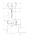
- FIG. 1in a partial cut-away view, illustrates a non interrupting on-line water distribution pressure monitoring system for a dry barrel fire hydrant in accordance with a preferred embodiment of the present invention
- FIG. 2in a schematic view, illustrates the non interrupting on-line water distribution pressure monitoring system for a dry barrel fire hydrant of FIG. 1 .
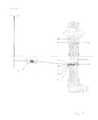
- FIG. 3in a schematic view, illustrates a non interrupting on-line water distribution pressure monitoring system for a wet barrel fire hydrant in accordance with a preferred embodiment of the present invention.
- FIG. 4in a schematic view, illustrates a non interrupting on-line water distribution pressure monitoring system for a dry barrel fire hydrant in accordance with an alternate preferred embodiment of the present invention.
- Fire hydrantstypically are either dry barrel hydrant used in colder climates or wet barrel hydrants for warm climates. Due to the construction of a typical fire hydrant and limitations based on climate (freezing), it is difficult to get accurate data with respect to water distribution and water pressure. For years the construction and operation of dry barrel compression type hydrants has not changed significantly. These hydrants generally consist of the bonnet, head, barrel, boot, operating rod, and the ball and seat assembly. The rotation of the operating nut located on top of the head bonnet will either raise or lower the operating rod, in turn seating or unseating the ball from the seat causing water to flow or stop flowing through the fire hydrant.
- Water distribution systemsare normally designed with hydrant placements typically every 500 feet. All hydrants are piped to the water main through a hydrant lead or a hydrant lateral, usually 6′′ in diameter or greater. The fire hydrant lead feeds the hydrant only from the main, no other lines should be connected this feed therefore eliminating pressure monitoring interferences.
- fire hydrantsare conveniently located they are the obvious vehicle to use for monitoring. Fire hydrants are however in constant use so water pressure monitoring can be hampered using traditional devices. Traditional devices require that the fire hydrant be partially dismantled to have water distribution assessed. Also due to the nature of most dry barrel hydrants, access to the hydrant is really restricted to the summer and can not occur in the winter. The instant device allows a fire hydrant to be in use while still being able to monitor water distribution and pressure. This ability is incredibly valuable during emergency situations as it provides a real-time snap shot of the availability of water in the system. Furthermore the instant invention allows for access to the required information year round and is not restricted to the summer or when the hydrant is not in use. Finally the instant invention is a cost effective as it does not require extensive retrofitting or refurbishing which can be costly to municipalities.
- the non interrupting on-line water distribution pressure monitoring system for a dry barrel fire hydrant 10includes an upper portion or the head 16 and a lower portion or the barrel 18 having an opening 20 .
- a water flow control mechanism 22is mounted at the bottom opening 20 of the barrel 18 for controlling the water flowing through the barrel 18 .
- An operating rod 24 for activating the water flow control mechanism 22 having an upper operating rod 26 and a lower operating rod 28extends through the barrel 18 to the upper portion the head 16 of the hydrant 10 .
- the upper operating rod 26is secured to the head 16 and the lower operating rod 28 is secured through the water flow control mechanism 22 to extend beyond the bottom end of the barrel 18 .
- a water pressure measuring device 30is housed within the lower operating rod 28 and extends beyond the bottom of the lower operating rod 28 .
- a communication mechanism 32positioned remotely from the dry barrel fire hydrant for receipt, collection and distribution of information collected from the water pressure measuring device 30 .
- the water flow control mechanism 22may be further defined as a ball and seat assembly 34 by way of example only.
- the bottom of the lower operating rod 28actually extends through the ball and seat assembly 34 .
- the bottom of the lower operating rod 28has a hollow portion 36 to allow for the water pressure measuring device 30 to be housed within the bottom of the lower operating rod.
- Lower operating rod 28will be a stainless steel rod that are traditionally either round or square in configuration depending on the hydrant manufacturer. Furthermore the use of stainless steel results in lower maintenance costs as the rod does not need to be replaced as frequently as traditional devices.
- the lower operating rod 28has a top end 38 that is designed to be connected to the bottom of upper operating rod 24 that has a break away coupling 40 located close to ground level.
- the bottom of the lower operating rod 28 of the instant inventionincludes a hole bored 4 to 5 inches in from the bottom of the operating rod 24 to achieve the hollow portion 36 .
- the water pressure measuring device 30may be further defined as a submersible pressure transducer and transducer cable 44 .
- the submersible pressure transducerincludes a transducer sensor 46 .
- the transducer sensor 46protrudes approximately 1 ⁇ 2 inch out the bottom of the lower operating rod 28 into the water.
- the lower operating rod 28further includes apertures 48 in the hollow portion 36 to allow for the transducer cable 44 to pass from the hollow portion 36 of the operating rod 24 to the lower portion of the barrel 18 .
- the lower operating rod 28further includes a channel 50 for accepting and securing the transducer cable 44 to the lower operating rod 28 .
- a retainer collar or ringis used to secure the transducer cable 44 to the channel 50 .
- the bored end of the lower operating rod 28further includes a series of channels 52 adjacent to the placement of the water pressure monitoring device 30 which are adapted to receive a sealing mechanism 54 for ensuring water does not flow past the pressure monitoring device 30 into the barrel 18 . More specifically two channels are cut approximately 1′′ inside the hollow portion 36 to house the o-rings, by way of example only of the sealing mechanism 54 , which form the seal required to stop the water from flowing past the submersible pressure transducer into the barrel 18 of the hydrant.
- the communication mechanism 32may be further defined as a remotely positioned ground vault 56 having a data logger 58 connected to the transducer cable 44 . Furthermore the communication of data from the data logger 58 may be conducted wirelessly.
- the lower operating rod 28further includes apertures 48 in the hollow portion 36 to allow for the transducer cable 44 to pass from the hollow portion 36 of the lower operating rod 28 to the lower portion of the barrel 18 . Specifically a small hole would be bored into the lower operating rod to allow the transducer cable 44 from the submersible pressure transducer to be passed through to the inside of the barrel 18 of the hydrant, then pressed into the channel 50 cut into the side of the lower operating rod 28 .
- the transducer cable 44would be securely fastened near the top of the lower rod 28 before exiting through the wall of the barrel 18 to the data logger 58 located inside a ground vault 56 or located inside a secure container on top of a sign post.
- the sign postmay include an antenna, and if required a box housing the data logger, batteries etc.
- a non interrupting on-line water distribution pressure monitoring system for a wet barrel fire hydrant 60In accordance with another embodiment of the present invention there is provided a non interrupting on-line water distribution pressure monitoring system for a wet barrel fire hydrant 60 .
- Wet barrel fire hydrantsdo not require operating rod modification.
- the water pressure measuring devicemay be positioned into the side of the hydrant barrel just below the ground.
- the non interrupting on-line water distribution pressure monitoring system for a wet barrel fire hydrant 60includes an upper portion having a pressurized head 64 and a lower portion having a pressurized barrel 62 having an adaptor 70 that passes through the wall 68 of the barrel 62 .
- the system 60further includes a water pressure measuring device 72 for measuring pressure having a sensing end 76 and cable end 74 , and mounted within the adaptor 70 whereby the sensing end 76 extends into the pressurized barrel 62 and the wire end 74 is outside of the pressurized barrel 62 .
- a communication mechanism 78may be positioned remotely from the wet barrel fire hydrant for receipt, collection and distribution of information collected from sensing end 76 of the water pressure measuring device 72 .
- the water pressure measuring device 72may be further defined as a submersible pressure transducer with sensor and transducer cable operating similarly to the description for the dry barrel fire hydrant system noted above.
- the communication mechanism 78may be in a remotely positioned ground vault having a data logger connected to the transducer cable with similar arrangements to those noted with the dry barrel fire hydrant.
- a non interrupting on-line water distribution pressure monitoring system for a wet barrel fire hydrant 60In accordance with another embodiment of the present invention there is provided a non interrupting on-line water distribution pressure monitoring system for a wet barrel fire hydrant 60 .
- Wet barrel fire hydrantsdo not require operating rod modification.
- the water pressure measuring devicemay be positioned into the side of the hydrant barrel just below the ground.
- the non interrupting on-line water distribution pressure monitoring system for a wet barrel fire hydrant 60includes an upper portion 63 having a pressurized head 64 and a lower portion 61 having a pressurized barrel 62 having an adaptor 70 that passes through the wall 68 of the barrel 62 .
- the system 60further includes a water pressure measuring device 72 for measuring pressure having a sensing end 76 and cable end 74 , and mounted within the adaptor 70 whereby the sensing end 76 extends into the pressurized barrel 62 and the wire end 74 is outside of the pressurized barrel 62 .
- a communication mechanism 78may be positioned remotely from the wet barrel fire hydrant for receipt, collection and distribution of information collected from sensing end 76 of the water pressure measuring device 72 .
- the water pressure measuring device 72may be further defined as a submersible pressure transducer with sensor 77 and transducer cable 79 operating similarly to the description for the dry barrel fire hydrant system noted above.
- the communication mechanism 78may be in a remotely positioned ground vault having a data logger connected to the transducer cable with similar arrangements to those noted with the dry barrel fire hydrant.
Landscapes
- Health & Medical Sciences (AREA)
- Life Sciences & Earth Sciences (AREA)
- Engineering & Computer Science (AREA)
- Hydrology & Water Resources (AREA)
- Public Health (AREA)
- Water Supply & Treatment (AREA)
- Measuring Fluid Pressure (AREA)
- Arrangements For Transmission Of Measured Signals (AREA)
Abstract
Description
Claims (14)
Priority Applications (5)
| Application Number | Priority Date | Filing Date | Title |
|---|---|---|---|
| US12/827,318US8589092B2 (en) | 2010-06-30 | 2010-06-30 | Non interrupting on-line water distribution pressure monitoring system for compression type wet and dry barrel fire hydrants |
| CA2801242ACA2801242C (en) | 2010-06-30 | 2011-06-28 | Non interrupting on-line water distribution pressure monitoring system for compression type wet and dry barrel fire hydrants |
| AU2011274272AAU2011274272B2 (en) | 2010-06-30 | 2011-06-28 | Non interrupting on-line water distribution pressure monitoring system for compression type wet and dry barrel fire hydrants |
| PCT/CA2011/000746WO2012000088A1 (en) | 2010-06-30 | 2011-06-28 | Non interrupting on-line water distribution pressure monitoring system for compression type wet and dry barrel fire hydrants |
| EP11800012.4AEP2588673A4 (en) | 2010-06-30 | 2011-06-28 | Non interrupting on-line water distribution pressure monitoring system for compression type wet and dry barrel fire hydrants |
Applications Claiming Priority (1)
| Application Number | Priority Date | Filing Date | Title |
|---|---|---|---|
| US12/827,318US8589092B2 (en) | 2010-06-30 | 2010-06-30 | Non interrupting on-line water distribution pressure monitoring system for compression type wet and dry barrel fire hydrants |
Publications (2)
| Publication Number | Publication Date |
|---|---|
| US20120004866A1 US20120004866A1 (en) | 2012-01-05 |
| US8589092B2true US8589092B2 (en) | 2013-11-19 |
Family
ID=45400329
Family Applications (1)
| Application Number | Title | Priority Date | Filing Date |
|---|---|---|---|
| US12/827,318Active2032-03-27US8589092B2 (en) | 2010-06-30 | 2010-06-30 | Non interrupting on-line water distribution pressure monitoring system for compression type wet and dry barrel fire hydrants |
Country Status (5)
| Country | Link |
|---|---|
| US (1) | US8589092B2 (en) |
| EP (1) | EP2588673A4 (en) |
| AU (1) | AU2011274272B2 (en) |
| CA (1) | CA2801242C (en) |
| WO (1) | WO2012000088A1 (en) |
Cited By (13)
| Publication number | Priority date | Publication date | Assignee | Title |
|---|---|---|---|---|
| US10612216B2 (en)* | 2018-09-06 | 2020-04-07 | Kennedy Valve Company | Apparatus and method to mount sensors below a main valve of a fire hydrant |
| US10921304B2 (en) | 2015-09-21 | 2021-02-16 | AMI Investments, LLC | Remote monitoring of water distribution system |
| US10934693B2 (en) | 2019-06-07 | 2021-03-02 | Mueller International, Llc | Hydrant monitoring system |
| US10941545B2 (en) | 2019-06-07 | 2021-03-09 | Mueller International, Llc | Hydrant monitoring system |
| US10968609B2 (en) | 2019-06-07 | 2021-04-06 | Mueller International, Llc | Self-contained hydrant monitoring system |
| US11067464B2 (en)* | 2019-01-18 | 2021-07-20 | Mueller International, Llc | Wet barrel hydrant with pressure monitoring and leak detection |
| US11167161B1 (en) | 2018-07-10 | 2021-11-09 | Senthuran Pon Suntharalingam | Hydrant monitoring system |
| US11313748B2 (en) | 2019-01-18 | 2022-04-26 | Mueller International, Llc | Pressure monitor housing with cap-engaging projection |
| US11400328B2 (en)* | 2019-06-07 | 2022-08-02 | Mueller International, Llc | Hydrant monitoring communications hub |
| US11988656B2 (en) | 2015-09-21 | 2024-05-21 | Mcwane, Inc. | Remote monitoring of water distribution system |
| US12078572B2 (en) | 2019-05-31 | 2024-09-03 | Mueller International, Llc | Hydrant nozzle cap |
| US12084844B2 (en) | 2020-05-14 | 2024-09-10 | Mueller International, Llc | Hydrant nozzle cap adapter |
| US12212053B2 (en) | 2016-02-12 | 2025-01-28 | Mueller International, Llc | Nozzle cap multi-band antenna assembly |
Families Citing this family (25)
| Publication number | Priority date | Publication date | Assignee | Title |
|---|---|---|---|---|
| US8931505B2 (en) | 2010-06-16 | 2015-01-13 | Gregory E. HYLAND | Infrastructure monitoring devices, systems, and methods |
| US9291520B2 (en) | 2011-08-12 | 2016-03-22 | Mueller International, Llc | Fire hydrant leak detector |
| US9287963B2 (en)* | 2012-04-20 | 2016-03-15 | Mueller International, Llc | Relay modules for communication within a mesh network |
| HRP20120603A2 (en) | 2012-07-23 | 2014-01-31 | Igor IGNAC | Telemetry hydrant for measuring, collecting and wireless sending measured values into database on remote computer |
| DK2912416T3 (en) | 2012-10-26 | 2018-09-10 | Mueller Int Llc | Detecting Leaks in a Fluid Distribution System |
| CH707425A1 (en)* | 2012-12-31 | 2014-07-15 | Hinni Ag | Monitoring device for a water supply network. |
| US9528903B2 (en) | 2014-10-01 | 2016-12-27 | Mueller International, Llc | Piezoelectric vibration sensor for fluid leak detection |
| CN104818767A (en)* | 2015-04-28 | 2015-08-05 | 上海电机学院 | Anti-blockage device and anti-blockage method for drainage pipeline |
| DE202015006930U1 (en) | 2015-09-29 | 2015-11-10 | Berliner Wasserbetriebe Anstalt des öffentlichen Rechts | Retractable removal fitting |
| US9670650B2 (en) | 2015-11-09 | 2017-06-06 | Sensus Spectrum Llc | Fire hydrant monitoring system |
| US10283857B2 (en) | 2016-02-12 | 2019-05-07 | Mueller International, Llc | Nozzle cap multi-band antenna assembly |
| CN105625514A (en)* | 2016-03-16 | 2016-06-01 | 上海伟梦物联网科技有限公司 | Intelligent fire hydrant device |
| CN106621156A (en)* | 2016-10-27 | 2017-05-10 | 江苏金米智能科技有限责任公司 | Water pressure monitoring system based on wireless communication for fire hydrants |
| US10859462B2 (en) | 2018-09-04 | 2020-12-08 | Mueller International, Llc | Hydrant cap leak detector with oriented sensor |
| US11342656B2 (en) | 2018-12-28 | 2022-05-24 | Mueller International, Llc | Nozzle cap encapsulated antenna system |
| EP4215677A1 (en)* | 2019-04-30 | 2023-07-26 | Mueller International, LLC | Outer housing for a pressure monitoring system |
| DE102019119258A1 (en)* | 2019-07-16 | 2021-01-21 | VAG GmbH | Fitting |
| CN110398312B (en)* | 2019-08-16 | 2024-04-05 | 湖南启泰传感科技有限公司 | Intelligent outdoor hydrant remote water pressure monitoring terminal and intelligent outdoor hydrant |
| US11186971B1 (en)* | 2020-05-29 | 2021-11-30 | Mueller International, Llc | Auxiliary valve for hydrant |
| CN111781067B (en)* | 2020-07-18 | 2024-10-25 | 淮阴工学院 | Pipeline network hydraulic testing device |
| US11613877B2 (en)* | 2020-10-01 | 2023-03-28 | AMI Investments, LLC | Monitoring apparatus for hydrant |
| CN113813543B (en)* | 2020-10-16 | 2022-09-16 | 湖北亿立能科技股份有限公司 | Intelligent fire hydrant water pressure change monitoring system |
| CN113262419B (en)* | 2021-05-28 | 2022-07-01 | 杭州传感器有限公司 | Fire hydrant valve plug, fire fighting system and monitoring method of fire hydrant valve plug |
| US12038306B2 (en)* | 2021-08-12 | 2024-07-16 | Silversmith, Inc. | Sensor conduit support structure |
| CH719177B1 (en)* | 2021-11-26 | 2025-01-15 | Hinni Ag | Hydrant with monitoring device. |
Citations (14)
| Publication number | Priority date | Publication date | Assignee | Title |
|---|---|---|---|---|
| GB614963A (en) | 1946-07-17 | 1948-12-30 | Merryweather & Sons | Improvements in apparatus for measuring the flow of water from fire hydrants, water mains, and the like |
| US4335608A (en)* | 1980-06-23 | 1982-06-22 | Wood Russell J | Submersible pressure transducer device |
| JPH02291917A (en) | 1989-05-02 | 1990-12-03 | Kubota Corp | Measuring device for hydraulic and water quality data of existing pipes |
| FR2792070A1 (en) | 1999-04-06 | 2000-10-13 | Suez Lyonnaise Des Eaux | APPARATUS FOR MEASURING AND RECORDING THE PRESSURE OF A WATER DISTRIBUTION NETWORK |
| US20020148294A1 (en)* | 1999-09-07 | 2002-10-17 | Anthony Bond | Deployment of equipment into fluid containers and conduits |
| US6816072B2 (en)* | 2001-12-07 | 2004-11-09 | Michael Zoratti | Fire hydrant anti-tamper device |
| US7099781B1 (en) | 2005-04-25 | 2006-08-29 | Heidl Jeremy N | Portable hydrant meter and system of use thereof |
| US7124036B2 (en) | 2004-06-25 | 2006-10-17 | Underground Utility Services, Inc. | Method and system for determining demand in a water distribution system |
| US20070255515A1 (en) | 2006-05-01 | 2007-11-01 | Hansa Consult Of North America, Llc | Methods, systems, and computer program products for automatically detecting leaks in a type III hydrant fuel piping system |
| US20080281534A1 (en) | 2007-05-07 | 2008-11-13 | Hurley Lyndon J | Flow testing system for fluid networks |
| US20090133887A1 (en)* | 2007-07-23 | 2009-05-28 | Rodolfo Garcia | Adaptable water connection for fire fighting equipment and connection device |
| US20100156632A1 (en)* | 2008-10-27 | 2010-06-24 | Mueller International, Inc. | Infrastructure monitoring system and method |
| US20100212396A1 (en)* | 2009-02-24 | 2010-08-26 | Brett Zenisek | Downhole sensor apparatus and method |
| US20110168265A1 (en)* | 2010-01-12 | 2011-07-14 | Cheney Dale S | Water Hammer Prevention Valve and Method |
- 2010
- 2010-06-30USUS12/827,318patent/US8589092B2/enactiveActive
- 2011
- 2011-06-28WOPCT/CA2011/000746patent/WO2012000088A1/enactiveApplication Filing
- 2011-06-28CACA2801242Apatent/CA2801242C/enactiveActive
- 2011-06-28EPEP11800012.4Apatent/EP2588673A4/ennot_activeWithdrawn
- 2011-06-28AUAU2011274272Apatent/AU2011274272B2/enactiveActive
Patent Citations (15)
| Publication number | Priority date | Publication date | Assignee | Title |
|---|---|---|---|---|
| GB614963A (en) | 1946-07-17 | 1948-12-30 | Merryweather & Sons | Improvements in apparatus for measuring the flow of water from fire hydrants, water mains, and the like |
| US4335608A (en)* | 1980-06-23 | 1982-06-22 | Wood Russell J | Submersible pressure transducer device |
| JPH02291917A (en) | 1989-05-02 | 1990-12-03 | Kubota Corp | Measuring device for hydraulic and water quality data of existing pipes |
| FR2792070A1 (en) | 1999-04-06 | 2000-10-13 | Suez Lyonnaise Des Eaux | APPARATUS FOR MEASURING AND RECORDING THE PRESSURE OF A WATER DISTRIBUTION NETWORK |
| US20020148294A1 (en)* | 1999-09-07 | 2002-10-17 | Anthony Bond | Deployment of equipment into fluid containers and conduits |
| US6816072B2 (en)* | 2001-12-07 | 2004-11-09 | Michael Zoratti | Fire hydrant anti-tamper device |
| US7124036B2 (en) | 2004-06-25 | 2006-10-17 | Underground Utility Services, Inc. | Method and system for determining demand in a water distribution system |
| US7099781B1 (en) | 2005-04-25 | 2006-08-29 | Heidl Jeremy N | Portable hydrant meter and system of use thereof |
| US7373261B2 (en) | 2005-04-25 | 2008-05-13 | Heidl Jeremy N | Portable hydrant meter and system of use thereof |
| US20070255515A1 (en) | 2006-05-01 | 2007-11-01 | Hansa Consult Of North America, Llc | Methods, systems, and computer program products for automatically detecting leaks in a type III hydrant fuel piping system |
| US20080281534A1 (en) | 2007-05-07 | 2008-11-13 | Hurley Lyndon J | Flow testing system for fluid networks |
| US20090133887A1 (en)* | 2007-07-23 | 2009-05-28 | Rodolfo Garcia | Adaptable water connection for fire fighting equipment and connection device |
| US20100156632A1 (en)* | 2008-10-27 | 2010-06-24 | Mueller International, Inc. | Infrastructure monitoring system and method |
| US20100212396A1 (en)* | 2009-02-24 | 2010-08-26 | Brett Zenisek | Downhole sensor apparatus and method |
| US20110168265A1 (en)* | 2010-01-12 | 2011-07-14 | Cheney Dale S | Water Hammer Prevention Valve and Method |
Cited By (30)
| Publication number | Priority date | Publication date | Assignee | Title |
|---|---|---|---|---|
| US11988656B2 (en) | 2015-09-21 | 2024-05-21 | Mcwane, Inc. | Remote monitoring of water distribution system |
| US12196736B2 (en) | 2015-09-21 | 2025-01-14 | Mcwane, Inc. | Remote monitoring of water distribution system |
| US12072327B2 (en) | 2015-09-21 | 2024-08-27 | Mcwane, Inc. | Remote monitoring of water distribution system |
| US10921304B2 (en) | 2015-09-21 | 2021-02-16 | AMI Investments, LLC | Remote monitoring of water distribution system |
| US11391712B2 (en) | 2015-09-21 | 2022-07-19 | AMI Investments, LLC | Remote monitoring of water distribution system |
| US11460459B2 (en) | 2015-09-21 | 2022-10-04 | AMI Investments, LLC | Remote monitoring of water distribution system |
| US11371977B2 (en) | 2015-09-21 | 2022-06-28 | AMI Investments, LLC | Remote monitoring of water distribution system |
| US12212053B2 (en) | 2016-02-12 | 2025-01-28 | Mueller International, Llc | Nozzle cap multi-band antenna assembly |
| US11167161B1 (en) | 2018-07-10 | 2021-11-09 | Senthuran Pon Suntharalingam | Hydrant monitoring system |
| US10612216B2 (en)* | 2018-09-06 | 2020-04-07 | Kennedy Valve Company | Apparatus and method to mount sensors below a main valve of a fire hydrant |
| US11067464B2 (en)* | 2019-01-18 | 2021-07-20 | Mueller International, Llc | Wet barrel hydrant with pressure monitoring and leak detection |
| US11313748B2 (en) | 2019-01-18 | 2022-04-26 | Mueller International, Llc | Pressure monitor housing with cap-engaging projection |
| US11971318B2 (en) | 2019-01-18 | 2024-04-30 | Mueller International, Llc | Pressure monitoring system and housing therefor |
| US11754456B2 (en) | 2019-01-18 | 2023-09-12 | Mueller International, Llc | Pressure monitoring system for wet barrel hydrant |
| US12078572B2 (en) | 2019-05-31 | 2024-09-03 | Mueller International, Llc | Hydrant nozzle cap |
| US20220290416A1 (en)* | 2019-06-07 | 2022-09-15 | Mueller International, Llc | Hydrant monitoring system |
| US11952755B2 (en) | 2019-06-07 | 2024-04-09 | Mueller International, Llc | Self-contained hydrant monitoring system |
| US11613876B2 (en)* | 2019-06-07 | 2023-03-28 | Mueller International, Llc | Hydrant monitoring system |
| US11619033B2 (en) | 2019-06-07 | 2023-04-04 | Mueller International, Llc | Self-contained hydrant monitoring system |
| US11400328B2 (en)* | 2019-06-07 | 2022-08-02 | Mueller International, Llc | Hydrant monitoring communications hub |
| US11839785B2 (en) | 2019-06-07 | 2023-12-12 | Mueller International, Llc | Hydrant monitoring communications hub |
| US11946233B2 (en)* | 2019-06-07 | 2024-04-02 | Mueller International, Llc | Hydrant monitoring system |
| US11591778B2 (en)* | 2019-06-07 | 2023-02-28 | Mueller International, Llc | Hydrant monitoring system |
| US11359360B2 (en) | 2019-06-07 | 2022-06-14 | Mueller International, Llc | Self-contained hydrant monitoring system |
| US20210198873A1 (en)* | 2019-06-07 | 2021-07-01 | Mueller International, Llc | Hydrant monitoring system |
| US10968609B2 (en) | 2019-06-07 | 2021-04-06 | Mueller International, Llc | Self-contained hydrant monitoring system |
| US20210079631A1 (en)* | 2019-06-07 | 2021-03-18 | Mueller International, Llc | Hydrant monitoring system |
| US10934693B2 (en) | 2019-06-07 | 2021-03-02 | Mueller International, Llc | Hydrant monitoring system |
| US10941545B2 (en) | 2019-06-07 | 2021-03-09 | Mueller International, Llc | Hydrant monitoring system |
| US12084844B2 (en) | 2020-05-14 | 2024-09-10 | Mueller International, Llc | Hydrant nozzle cap adapter |
Also Published As
| Publication number | Publication date |
|---|---|
| AU2011274272A1 (en) | 2013-02-07 |
| CA2801242A1 (en) | 2012-01-05 |
| CA2801242C (en) | 2014-05-06 |
| US20120004866A1 (en) | 2012-01-05 |
| AU2011274272B2 (en) | 2015-05-07 |
| EP2588673A4 (en) | 2016-05-25 |
| EP2588673A1 (en) | 2013-05-08 |
| WO2012000088A1 (en) | 2012-01-05 |
Similar Documents
| Publication | Publication Date | Title |
|---|---|---|
| US8589092B2 (en) | Non interrupting on-line water distribution pressure monitoring system for compression type wet and dry barrel fire hydrants | |
| US11391712B2 (en) | Remote monitoring of water distribution system | |
| US7983869B1 (en) | Flow testing system for fluid networks | |
| US7917324B2 (en) | Flow testing system for fluid networks | |
| EP2314997B1 (en) | System and method for detecting leaks in a pipeline network | |
| CN109404736B (en) | Intelligent urban pipeline damage early warning system | |
| US20120206272A1 (en) | Device for detecting a blockage of a mechanical fluid meter, and meter featuring blockage detection | |
| US20120232750A1 (en) | Transport of fluids | |
| KR101204426B1 (en) | Real-time monitoring system for flood | |
| KR20170038481A (en) | Precipitation measuring device using the sensor | |
| CN209417913U (en) | A kind of anti-waterflooding early warning system of pump house | |
| KR101939126B1 (en) | Apparatus for inspecting firefighting facility in apartment house | |
| US11988656B2 (en) | Remote monitoring of water distribution system | |
| KR100556058B1 (en) | Sewage sediment height and flow measurement system using pressure gauge, water gauge and flow meter | |
| KR20220061111A (en) | leak detection system | |
| CA3149224A1 (en) | Remote monitoring of water distribution system | |
| US10005426B2 (en) | Combination fuel monitoring and anti-theft device and system | |
| US11331524B1 (en) | Fire suppression system fluid accumulation and temperature monitoring system and method of making and using the same | |
| US11698319B2 (en) | Sampling meter resetter and pressure transmitter combination | |
| US20250160271A1 (en) | Irrigation system and method for controlling and managing irrigation | |
| WO2024013528A1 (en) | Fire hydrant with improved sensing and operating properties and method for reporting the operational status of the fire hydrant | |
| CN113237680A (en) | Water consumption state detection system and detection method for fire hydrant | |
| JP2024511803A (en) | An anti-vandalism mounting system for monitoring physical variables of water, the system comprising a first member, a second member, a third member, and a fourth member, the first member housing a plurality of devices. Systems and assembly procedures with multiple compartments for | |
| CN116363837A (en) | Landslide geological disaster early warning system |
Legal Events
| Date | Code | Title | Description |
|---|---|---|---|
| AS | Assignment | Owner name:2236128 ONTARIO INC., CANADA Free format text:ASSIGNMENT OF ASSIGNORS INTEREST;ASSIGNORS:PLOUFFE, DON;NISSEN, RICK;REEL/FRAME:025058/0271 Effective date:20100630 | |
| STCF | Information on status: patent grant | Free format text:PATENTED CASE | |
| FEPP | Fee payment procedure | Free format text:PAYOR NUMBER ASSIGNED (ORIGINAL EVENT CODE: ASPN); ENTITY STATUS OF PATENT OWNER: SMALL ENTITY | |
| FPAY | Fee payment | Year of fee payment:4 | |
| MAFP | Maintenance fee payment | Free format text:PAYMENT OF MAINTENANCE FEE, 8TH YR, SMALL ENTITY (ORIGINAL EVENT CODE: M2552); ENTITY STATUS OF PATENT OWNER: SMALL ENTITY Year of fee payment:8 | |
| AS | Assignment | Owner name:DIGITAL WATER SOLUTIONS INC., CANADA Free format text:ASSIGNMENT OF ASSIGNORS INTEREST;ASSIGNOR:2236128 ONTARIO INC.;REEL/FRAME:060565/0262 Effective date:20220501 | |
| MAFP | Maintenance fee payment | Free format text:PAYMENT OF MAINTENANCE FEE, 12TH YR, SMALL ENTITY (ORIGINAL EVENT CODE: M2553); ENTITY STATUS OF PATENT OWNER: SMALL ENTITY Year of fee payment:12 |