US8589014B2 - Sensor field selection - Google Patents
Sensor field selectionDownload PDFInfo
- Publication number
- US8589014B2 US8589014B2US13/150,385US201113150385AUS8589014B2US 8589014 B2US8589014 B2US 8589014B2US 201113150385 AUS201113150385 AUS 201113150385AUS 8589014 B2US8589014 B2US 8589014B2
- Authority
- US
- United States
- Prior art keywords
- vehicle
- sensor
- change
- control strategy
- sensors
- Prior art date
- Legal status (The legal status is an assumption and is not a legal conclusion. Google has not performed a legal analysis and makes no representation as to the accuracy of the status listed.)
- Active, expires
Links
Images


Classifications
- G—PHYSICS
- G05—CONTROLLING; REGULATING
- G05D—SYSTEMS FOR CONTROLLING OR REGULATING NON-ELECTRIC VARIABLES
- G05D1/00—Control of position, course, altitude or attitude of land, water, air or space vehicles, e.g. using automatic pilots
- G05D1/02—Control of position or course in two dimensions
- G05D1/021—Control of position or course in two dimensions specially adapted to land vehicles
- G05D1/0231—Control of position or course in two dimensions specially adapted to land vehicles using optical position detecting means
- G05D1/0238—Control of position or course in two dimensions specially adapted to land vehicles using optical position detecting means using obstacle or wall sensors
- G05D1/024—Control of position or course in two dimensions specially adapted to land vehicles using optical position detecting means using obstacle or wall sensors in combination with a laser
- G—PHYSICS
- G05—CONTROLLING; REGULATING
- G05D—SYSTEMS FOR CONTROLLING OR REGULATING NON-ELECTRIC VARIABLES
- G05D1/00—Control of position, course, altitude or attitude of land, water, air or space vehicles, e.g. using automatic pilots
- G05D1/80—Arrangements for reacting to or preventing system or operator failure
- G05D1/81—Handing over between on-board automatic and on-board manual control
- B—PERFORMING OPERATIONS; TRANSPORTING
- B60—VEHICLES IN GENERAL
- B60W—CONJOINT CONTROL OF VEHICLE SUB-UNITS OF DIFFERENT TYPE OR DIFFERENT FUNCTION; CONTROL SYSTEMS SPECIALLY ADAPTED FOR HYBRID VEHICLES; ROAD VEHICLE DRIVE CONTROL SYSTEMS FOR PURPOSES NOT RELATED TO THE CONTROL OF A PARTICULAR SUB-UNIT
- B60W30/00—Purposes of road vehicle drive control systems not related to the control of a particular sub-unit, e.g. of systems using conjoint control of vehicle sub-units
- B60W30/08—Active safety systems predicting or avoiding probable or impending collision or attempting to minimise its consequences
- B—PERFORMING OPERATIONS; TRANSPORTING
- B60—VEHICLES IN GENERAL
- B60W—CONJOINT CONTROL OF VEHICLE SUB-UNITS OF DIFFERENT TYPE OR DIFFERENT FUNCTION; CONTROL SYSTEMS SPECIALLY ADAPTED FOR HYBRID VEHICLES; ROAD VEHICLE DRIVE CONTROL SYSTEMS FOR PURPOSES NOT RELATED TO THE CONTROL OF A PARTICULAR SUB-UNIT
- B60W40/00—Estimation or calculation of non-directly measurable driving parameters for road vehicle drive control systems not related to the control of a particular sub unit, e.g. by using mathematical models
- B60W40/02—Estimation or calculation of non-directly measurable driving parameters for road vehicle drive control systems not related to the control of a particular sub unit, e.g. by using mathematical models related to ambient conditions
- G—PHYSICS
- G05—CONTROLLING; REGULATING
- G05D—SYSTEMS FOR CONTROLLING OR REGULATING NON-ELECTRIC VARIABLES
- G05D1/00—Control of position, course, altitude or attitude of land, water, air or space vehicles, e.g. using automatic pilots
- G05D1/02—Control of position or course in two dimensions
- G05D1/021—Control of position or course in two dimensions specially adapted to land vehicles
- G05D1/0231—Control of position or course in two dimensions specially adapted to land vehicles using optical position detecting means
- G05D1/0246—Control of position or course in two dimensions specially adapted to land vehicles using optical position detecting means using a video camera in combination with image processing means
- G—PHYSICS
- G05—CONTROLLING; REGULATING
- G05D—SYSTEMS FOR CONTROLLING OR REGULATING NON-ELECTRIC VARIABLES
- G05D1/00—Control of position, course, altitude or attitude of land, water, air or space vehicles, e.g. using automatic pilots
- G05D1/02—Control of position or course in two dimensions
- G05D1/021—Control of position or course in two dimensions specially adapted to land vehicles
- G05D1/0255—Control of position or course in two dimensions specially adapted to land vehicles using acoustic signals, e.g. ultra-sonic singals
- G—PHYSICS
- G05—CONTROLLING; REGULATING
- G05D—SYSTEMS FOR CONTROLLING OR REGULATING NON-ELECTRIC VARIABLES
- G05D1/00—Control of position, course, altitude or attitude of land, water, air or space vehicles, e.g. using automatic pilots
- G05D1/40—Control within particular dimensions
- G05D1/43—Control of position or course in two dimensions
- G—PHYSICS
- G05—CONTROLLING; REGULATING
- G05D—SYSTEMS FOR CONTROLLING OR REGULATING NON-ELECTRIC VARIABLES
- G05D2111/00—Details of signals used for control of position, course, altitude or attitude of land, water, air or space vehicles
- G05D2111/10—Optical signals
- G—PHYSICS
- G05—CONTROLLING; REGULATING
- G05D—SYSTEMS FOR CONTROLLING OR REGULATING NON-ELECTRIC VARIABLES
- G05D2111/00—Details of signals used for control of position, course, altitude or attitude of land, water, air or space vehicles
- G05D2111/20—Acoustic signals, e.g. ultrasonic signals
Definitions
- Autonomous vehiclesuse various computing systems to aid in the transport of passengers from one location to another. Some autonomous vehicles may require some initial input or continuous input from an operator, such as a pilot, driver, or passenger. Other systems, for example autopilot systems, may be used only when the system has been engaged, which permits the operator to switch from a manual mode (where the operator exercises a high degree of control over the movement of the vehicle) to an autonomous mode (where the vehicle essentially drives itself) to modes that lie somewhere in between.
- a manual modewhere the operator exercises a high degree of control over the movement of the vehicle
- autonomous modewhere the vehicle essentially drives itself
- autonomous vehiclesare equipped with various types of sensors in order to detect objects in the surroundings.
- autonomous vehiclesmay include lasers, sonar, radar, cameras, and other devices which scan and record data from the vehicle's surroundings. These devices in combination (and in some cases alone) may be used to build 3D models of the objects detected in the vehicle's surrounding.
- One aspect of the disclosureprovides a method for controlling a vehicle having an autonomous operation mode.
- the methodincludes controlling, by a processor, operation of the vehicle based on a first control strategy; identifying a sensor field based on a field of view of one or more sensors of the vehicle; receiving sensor data from selected ones of the one or more sensors; identifying a change in sensor perception of the one or more sensors based on the sensor data, the change in the sensor perception including a diminished ability to detect objects within the sensor field; determining a second control strategy based on the change; and controlling, by the processor, the operation of the vehicle based on the second control strategy.
- the methodalso includes detecting an object and a location of the object in the sensor field based on the received sensor data and identifying the change is based on the location of the object.
- identifying the change in sensor perceptionincludes calculating an area of diminished sensor perception based on the location of the object in the sensor field, and determining the second control strategy is based on the area of diminished sensor perception.
- identifying the change in sensor perceptionincludes calculating a current sensor field based on the location of the object in the sensor field, and determining the second control strategy is based on the current sensor field.
- the objectis another vehicle.
- the methodalso includes determining that the sensor data indicates that a given one of the one or more sensors is providing unreliable information; and identifying the change is based on the determined indication.
- the unreliable informationincludes one or more camera images.
- the methodalso includes determining that there is no longer a change in sensor perception of the one or more sensors based on the sensor data; controlling the operation of the vehicle is further based on the first control strategy based on the determination that there is no longer a change.
- controlling the operation of the vehicle based on the first control strategyincludes maneuvering the vehicle in a first direction
- controlling the operation of the vehicle based on the second control strategyincludes maneuvering the vehicle in a second direction different from the first direction.
- controlling the operation of the vehicle based on the first control strategyincludes maneuvering the vehicle at a first speed and wherein controlling the operation of the vehicle based on the second control strategy includes maneuvering the vehicle at a second speed different from the first speed.
- the deviceincludes one or more sensors for detecting objects in the vehicle's surroundings and a processor coupled to the one or more sensors.
- the processoris operable to control operation of the vehicle based on a first control strategy; identify a sensor field based on a field of view of the one or more sensors of the vehicle; receive sensor data from selected ones of the one or more sensors; identify a change in sensor perception of the one or more sensors based on the sensor data, the change in the sensor perception including a diminished ability to detect objects within the sensor field; determine a second control strategy based on the change; and control the operation of the vehicle based on the second control strategy.
- the processoris further operable to detect an object and a location of the object in the sensor field based on the received sensor data and the processor identifies the change based on the location of the object.
- the processoris operable to identify the change in sensor perception by calculating an area of diminished sensor perception based on the location of the object in the sensor field, and determining the second control strategy is based on the area of diminished sensor perception.
- the processoris operable to identify the change in sensor perception by calculating a current sensor field based on the location of the object in the sensor field, and determining the second control strategy is based on the current sensor field.
- the processoris further operable to identify the object as another vehicle.
- the processoris further operable to determine that the sensor data indicates that a given one of the one or more sensors is providing unreliable information, and the processor identifies the change based on the determined indication.
- the unreliable informationincludes one or more camera images.
- the processoris also operable to determine that there is no longer a change in sensor perception of the one or more sensors based on the sensor data and to control the operation of the vehicle based on the first control strategy based on the determination that there is no longer a change.
- the processoris also operable to control the operation of the vehicle based on the first control strategy by maneuvering the vehicle in a first direction and to control the operation of the vehicle based on the second control strategy by maneuvering the vehicle in a second direction different from the first direction.
- the processoris also operable to control the operation of the vehicle based on the first control strategy by maneuvering the vehicle at a first speed and to control the operation of the vehicle based on the second control strategy by maneuvering the vehicle at a second speed different from the first speed.
- Yet another aspect of the disclosureprovides a tangible computer-readable storage medium on which computer readable instructions of a program are stored, the instructions, when executed by a processor, cause the processor to perform a method of controlling a vehicle having an autonomous operation mode.
- the methodincludes controlling, by a processor, operation of the vehicle based on a first control strategy; identifying a sensor field based on a field of view of one or more sensors of the vehicle, the change in the sensor perception including a diminished ability to detect objects within the sensor field; receiving sensor data from selected ones of the one or more sensors; identifying a change in sensor perception of the one or more sensors based on the sensor data; determining a second control strategy based on the change; and controlling, by the processor, the operation of the vehicle based on the second control strategy.
- the methodalso includes detecting an object and a location of the object in the sensor field based on the received sensor data and identifying the change is based on the location of the object.
- identifying the change in sensor perceptionincludes calculating an area of diminished sensor perception based on the location of the object in the sensor field, and determining the second control strategy is based on the area of diminished sensor perception.
- identifying the change in sensor perceptionincludes calculating a current sensor field based on the location of the object in the sensor field, and determining the second control strategy is based on the current sensor field.
- the objectis another vehicle.
- the methodalso includes determining that the sensor data indicates that a given one of the one or more sensors is providing unreliable information; and identifying the change is based on the determined indication.
- the unreliable informationincludes one or more camera images.
- the methodalso includes determining that there is no longer a change in sensor perception of the one or more sensors based on the sensor data; controlling the operation of the vehicle is further based on the first control strategy based on the determination that there is no longer a change.
- controlling the operation of the vehicle based on the first control strategyincludes maneuvering the vehicle in a first direction
- controlling the operation of the vehicle based on the second control strategyincludes maneuvering the vehicle in a second direction different from the first direction.
- controlling the operation of the vehicle based on the first control strategyincludes maneuvering the vehicle at a first speed and wherein controlling the operation of the vehicle based on the second control strategy includes maneuvering the vehicle at a second speed different from the first speed.
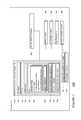
- FIG. 1is a functional diagram of a system in accordance with an exemplary embodiment.
- FIG. 2is an interior of an autonomous vehicle in accordance with an exemplary embodiment.
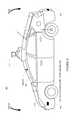
- FIG. 3is an exterior of an autonomous vehicle in accordance with an exemplary embodiment
- FIGS. 4A-Dare diagrams of an autonomous vehicle in accordance with an exemplary embodiment.
- FIGS. 5A-Bare diagrams of an autonomous vehicle in accordance with an exemplary embodiment.
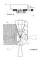
- FIGS. 6A-Bare diagrams of an autonomous vehicle in accordance with an exemplary embodiment.
- FIG. 7A-Bare diagrams of an autonomous vehicle in accordance with an exemplary embodiment.
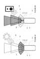
- FIGS. 8A-Bare diagrams of an autonomous vehicle in accordance with an exemplary embodiment.
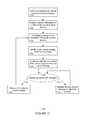
- FIG. 9is flow diagram in accordance with an exemplary embodiment.
- FIG. 10is flow diagram in accordance with an exemplary embodiment.
- FIG. 11is flow diagram in accordance with an exemplary embodiment.
- an autonomous driving system 100in accordance with one aspect of the disclosure includes a vehicle 101 with various components. While certain aspects of the disclosure are particularly useful in connection with specific types of vehicles, the vehicle may be any type of vehicle including, but not limited to, cars, trucks, motorcycles, busses, boats, airplanes, helicopters, lawnmowers, recreational vehicles, amusement park vehicles, farm equipment, construction equipment, trams, golf carts, trains, and trolleys.
- the vehiclemay have one or more computers, such as computer 110 containing a processor 120 , memory 130 and other components typically present in general purpose computers.
- the memory 130stores information accessible by processor 120 , including instructions 132 and data 134 that may be executed or otherwise used by the processor 120 .
- the memory 130may be of any type capable of storing information accessible by the processor, including a computer-readable medium, or other medium that stores data that may be read with the aid of an electronic device, such as a hard-drive, memory card, ROM, RAM, DVD or other optical disks, as well as other write-capable and read-only memories.
- Systems and methodsmay include different combinations of the foregoing, whereby different portions of the instructions and data are stored on different types of media.
- the instructions 132may be any set of instructions to be executed directly (such as machine code) or indirectly (such as scripts) by the processor.
- the instructionsmay be stored as computer code on the computer-readable medium.
- the terms “instructions” and “programs”may be used interchangeably herein.
- the instructionsmay be stored in object code format for direct processing by the processor, or in any other computer language including scripts or collections of independent source code modules that are interpreted on demand or compiled in advance. Functions, methods and routines of the instructions are explained in more detail below.
- the data 134may be retrieved, stored or modified by processor 120 in accordance with the instructions 132 .
- the datamay be stored in computer registers, in a relational database as a table having a plurality of different fields and records, XML documents or flat files.
- the datamay also be formatted in any computer-readable format.
- image datamay be stored as bitmaps comprised of grids of pixels that are stored in accordance with formats that are compressed or uncompressed, lossless (e.g., BMP) or lossy (e.g., JPEG), and bitmap or vector-based (e.g., SVG), as well as computer instructions for drawing graphics.
- the datamay comprise any information sufficient to identify the relevant information, such as numbers, descriptive text, proprietary codes, references to data stored in other areas of the same memory or different memories (including other network locations) or information that is used by a function to calculate the relevant data.
- the processor 120may be any conventional processor, such as commercially available CPUs. Alternatively, the processor may be a dedicated device such as an ASIC or other hardware-based processor.
- FIG. 1functionally illustrates the processor, memory, and other elements of computer 110 as being within the same block, it will be understood by those of ordinary skill in the art that the processor, computer, or memory may actually comprise multiple processors, computers, or memories that may or may not be stored within the same physical housing.
- memorymay be a hard drive or other storage media located in a housing different from that of computer 110 .
- references to a processor or computerwill be understood to include references to a collection of processors or computers or memories that may or may not operate in parallel.
- some of the componentssuch as steering components and deceleration components, may each have their own processor that only performs calculations related to the component's specific function.
- the processormay be located remote from the vehicle and communicate with the vehicle wirelessly. In other aspects, some of the processes described herein are executed on a processor disposed within the vehicle and others by a remote processor, including taking the steps necessary to execute a single maneuver.
- Computer 110may all of the components normally used in connection with a computer such as a central processing unit (CPU), memory (e.g., RAM and internal hard drives) storing data 134 and instructions such as a web browser, an electronic display 142 (e.g., a monitor having a screen, a small LCD touch-screen or any other electrical device that is operable to display information), user input 140 (e.g., a mouse, keyboard, touch screen and/or microphone), as well as various sensors (e.g., a video camera) for gathering explicit (e.g., a gesture) or implicit (e.g., “the person is asleep”) information about the states and desires of a person.
- a computersuch as a central processing unit (CPU), memory (e.g., RAM and internal hard drives) storing data 134 and instructions such as a web browser, an electronic display 142 (e.g., a monitor having a screen, a small LCD touch-screen or any other electrical device that is operable to display information), user input 140 (
- computer 110may be an autonomous driving computing system incorporated into vehicle 101 .
- FIG. 2depicts an exemplary design of the interior of an autonomous vehicle.
- the autonomous vehiclemay include all of the features of a non-autonomous vehicle, for example: a steering apparatus, such as steering wheel 210 ; a navigation display apparatus, such as navigation display 215 ; and a gear selector apparatus, such as gear shifter 220 .
- the vehiclemay also have various user input devices, such as gear shifter 220 , touch screen 217 , or button inputs 219 , for activating or deactivating one or more autonomous driving modes and for enabling a driver or passenger 290 to provide information, such as a navigation destination, to the autonomous driving computer 110 .
- Vehicle 101may include one or more additional displays.
- the vehiclemay include a display 225 for displaying information regarding the status of the autonomous vehicle or its computer.
- the vehiclemay include a status indicating apparatus 138 (see FIG. 1 ), such as status bar 230 , to indicate the current status of vehicle 101 .
- status bar 230displays “D” and “2 mph” indicating that the vehicle is presently in drive mode and is moving at 2 miles per hour.
- the vehiclemay display text on an electronic display, illuminate portions of vehicle 101 , such as steering wheel 210 , or provide various other types of indications.
- the autonomous driving computing systemmay capable of communicating with various components of the vehicle.
- computer 110may be in communication with the vehicle's central processor 160 and may send and receive information from the various systems of vehicle 101 , for example the braking 180 , acceleration 182 , signaling 184 , and navigation 186 systems in order to control the movement, speed, etc. of vehicle 101 .
- computer 110may control some or all of these functions of vehicle 101 and thus be fully or merely partially autonomous. It will be understood that although various systems and computer 110 are shown within vehicle 101 , these elements may be external to vehicle 101 or physically separated by large distances.
- the vehiclemay also include a geographic position component 144 in communication with computer 110 for determining the geographic location of the device.
- the position componentmay include a GPS receiver to determine the device's latitude, longitude and/or altitude position.
- Other location systemssuch as laser-based localization systems, inertial-aided GPS, or camera-based localization may also be used to identify the location of the vehicle.
- the location of the vehiclemay include an absolute geographical location, such as latitude, longitude, and altitude as well as relative location information, such as location relative to other cars immediately around it which can often be determined with less noise that absolute geographical location.
- the vehiclemay also include other devices in communication with computer 110 , such as an accelerometer, gyroscope or another direction/speed detection device 146 to determine the direction and speed of the vehicle or changes thereto.
- acceleration device 146may determine its pitch, yaw or roll (or changes thereto) relative to the direction of gravity or a plane perpendicular thereto.
- the devicemay also track increases or decreases in speed and the direction of such changes.
- the device's provision of location and orientation data as set forth hereinmay be provided automatically to the user, computer 110 , other computers and combinations of the foregoing.
- the computer 110may control the direction and speed of the vehicle by controlling various components.
- computer 110may cause the vehicle to accelerate (e.g., by increasing fuel or other energy provided to the engine), decelerate (e.g., by decreasing the fuel supplied to the engine or by applying brakes) and change direction (e.g., by turning the front two wheels).
- the vehiclemay also include components for detecting objects external to the vehicle such as other vehicles, obstacles in the roadway, traffic signals, signs, trees, etc.
- the detection systemmay include lasers, sonar, radar, cameras or any other detection devices which record data which may be processed by computer 110 .
- the vehicleis a small passenger vehicle, the car may include a laser mounted on the roof or other convenient location.
- small passenger vehicle 301may include lasers 310 and 311 , mounted on the front and top of the vehicle, respectively.
- Laser 310may have a range of approximately 150 meters, a thirty degree vertical field of view, and approximately a thirty degree horizontal field of view.
- Laser 311may have a range of approximately 50-80 meters, a thirty degree vertical field of view, and a 360 degree horizontal field of view.
- the lasersmay provide the vehicle with range and intensity information which the computer may use to identify the location and distance of various objects.
- the lasersmay measure the distance between the vehicle and the object surfaces facing the vehicle by spinning on its axis and changing its pitch.
- the vehiclemay also include various radar detection units, such as those used for adaptive cruise control systems.
- the radar detection unitsmay be located on the front and back of the car as well as on either side of the front bumper.
- vehicle 301includes radar detection units 320 - 323 located on the side (only one side being shown), front and rear of the vehicle.
- Each of these radar detection unitsmay have a range of approximately 200 meters for an approximately 18 degree field of view as well as a range of approximately 60 meters for an approximately 56 degree field of view.
- vehicle 301may include 2 cameras 330 - 331 mounted under a windshield 340 near the rear view mirror (not shown).
- Camera 330may include a range of approximately 200 meters and an approximately 30 degree horizontal field of view
- camera 331may include a range of approximately 100 meters and an approximately 60 degree horizontal field of view.
- FIG. 4Ais a top-down view of the approximate sensor fields of the various sensors.
- FIG. 4Bdepicts the approximate sensor fields 410 and 411 for lasers 310 and 311 , respectively based on the fields of view for these sensors.
- sensor field 410includes an approximately 30 degree horizontal field of view for approximately 150 meters
- sensor field 411includes a 360 degree horizontal field of view for approximately 80 meters.
- FIG. 4Cdepicts the approximate sensor fields 420 A- 423 B and for radar detection units 320 - 323 , respectively, based on the fields of view for these sensors.
- radar detection unit 320includes sensor fields 420 A and 420 B.
- Sensor field 420 Aincludes an approximately 18 degree horizontal field of view for approximately 200 meters
- sensor field 420 Bincludes an approximately 56 degree horizontal field of view for approximately 80 meters.
- radar detection units 321 - 323include sensor fields 421 A- 423 A and 421 B- 423 B.
- Sensor fields 421 A- 423 Ainclude an approximately 18 degree horizontal field of view for approximately 200 meters
- sensor fields 421 B- 423 Binclude an approximately 56 degree horizontal field of view for approximately 80 meters.
- Sensor fields 421 A and 422 Aextend passed the edge of FIGS. 4A and 4C .
- FIG. 4Ddepicts the approximate sensor fields 430 - 431 cameras 330 - 331 , respectively, based on the fields of view for these sensors.
- sensor field 430 of camera 330includes a field of view of approximately 30 degrees for approximately 200 meters
- sensor field 431 of camera 430includes a field of view of approximately 60 degrees for approximately 100 meters.
- an autonomous vehiclemay include sonar devices, stereo cameras, a localization camera, a laser, and a radar detection unit each with different fields of view.
- the sonarmay have a horizontal field of view of approximately 60 degrees for a maximum distance of approximately 6 meters.
- the stereo camerasmay have an overlapping region with a horizontal field of view of approximately 50 degrees, a vertical field of view of approximately 10 degrees, and a maximum distance of approximately 30 meters.
- the localization cameramay have a horizontal field of view of approximately 75 degrees, a vertical field of view of approximately 90 degrees and a maximum distance of approximately 10 meters.
- the lasermay have a horizontal field of view of approximately 360 degrees, a vertical field of view of approximately 30 degrees, and a maximum distance of 100 meters.
- the radarmay have a horizontal field of view of 60 degrees for the near beam, 30 degrees for the far beam, and a maximum distance of 200 meters.
- the vehicle 101may be a small cart, such as a golf cart.
- FIGS. 5A-5Bare a side and top-down view of small cart 501 and a set of exemplary fields of view which make up a sensor field of the cart.
- Small cart 501may include sensors such as sonar, stereo cameras, and a localization camera. The localization camera may be used to localize the vehicle to centimeter accuracy on a map of the map information. Each of these sensors may result in a field of view extending for some distance at some horizontal and vertical degrees.
- cart 501may include a localization camera mounted on the front of the cart which results in a sensor field 560 with a horizontal field of view of approximately 35 degrees which ranges approximately 1.5 to 7 meters in front of the cart.
- the cartmay also have a plurality of sonar detection devices mounted across the front of the cart. These sonar devices may be used to detect objects by transmitting and receiving sound waves at a particular frequency of range of frequencies. Each of these devices may result in a sensor field, such as sensor fields 570 - 575 , each with a horizontal field of view of approximately 35 degrees which range approximately 3 meters in front of the cart.
- Cart 501may also include stereo camera mounted in the front of the cart. The stereo cameras may result in a sensor field 580 , each with a horizontal field of view of approximately 30 degrees which ranges approximately 10 meters from the front of the cart.
- the cart cart's localization cameramay include a horizontal field of view of approximately 75 degrees, a vertical field of view of approximately 90 degrees, and a range of approximately 10 meters.
- the overlapping region of the stereo camerasmay include a horizontal field of view for approximately 50 degrees, a vertical field of view for approximately 10 degrees, and a range of approximately 30 meters.
- the sonar detection devicesmay each have a horizontal field of view of approximately 60 degrees and a range of approximately 6 meters.
- the aforementioned sensorsmay allow the vehicle to evaluate and potentially respond to its environment in order to maximize safety for passengers as well as objects or people in the environment. It will be understood that the vehicle types, number and type of sensors, the sensor locations, the sensor fields of view, and the sensors' sensor fields are merely exemplary. Various other configurations may also be utilized.
- the computermay also use input from sensors typical non-autonomous vehicles.
- these sensorsmay include tire pressure sensors, engine temperature sensors, brake heat sensors, breake pad status sensors, tire tread sensors, fuel sensors, oil level and quality sensors, air quality sensors (for detecting temperature, humidity, or particulates in the air), etc.
- sensorsprovide data that is processed by the computer in real-time, that is, the sensors may continuously update their output to reflect the environment being sensed at or over a range of time, and continuously or as-demanded provide that updated output to the computer so that the computer can determine whether the vehicle's then-current direction or speed should be modified in response to the sensed environment.
- data 134may include detailed map information 136 , e.g., highly detailed maps identifying the shape and elevation of roadways, lane lines, intersections, crosswalks, speed limits, traffic signals, buildings, signs, real time traffic information, or other such objects and information.
- map informationmay include explicit speed limit information associated with various roadway segments.
- the speed limit datamay be entered manually or scanned from previously taken images of a speed limit sign using, for example, optical-character recognition.
- the map informationmay include three-dimensional terrain maps incorporating one or more of objects listed above.
- the vehiclemay determine that another car is expected to turn based on real-time data (e.g., using its sensors to determine the current GPS position of another car) and other data (e.g., comparing the GPS position with previously-stored lane-specific map data to determine whether the other car is within a turn lane).
- real-time datae.g., using its sensors to determine the current GPS position of another car
- other datae.g., comparing the GPS position with previously-stored lane-specific map data to determine whether the other car is within a turn lane.
- the map informationis depicted herein as an image-based map, the map information need not be entirely image based (for example, raster).
- the map informationmay include one or more roadgraphs or graph networks of information such as roads, lanes, intersections, and the connections between these features.
- Each featuremay be stored as graph data and may be associated with information such as a geographic location and whether or not it is linked to other related features, for example, a stop sign may be linked to a road and an intersection, etc.
- the associated datamay include grid-based indices of a roadgraph to allow for efficient lookup of certain roadgraph features.
- An autonomous vehiclemay transport itself, passengers, and/or cargo between two locations by following a route. For example, a driver may input a destination and activate an autonomous mode of the vehicle. In response, the vehicle's computer may calculate a route based on the roadgraph, its current location, and the destination. Based on the route (or as part of the route generation), the vehicle may determine a control strategy for controlling the vehicle along the route to the destination. For example, the control strategy may include where to turn, at what speeds to travel, where to look for traffic signals, where to stop for intersections or stop signs, etc.
- the vehiclemay detect objects in its surroundings which are within the sensor fields.
- the computermay adjust the autonomous vehicle's speed or change direction.
- the sensor fieldsmay be changed or become less reliable based on objects or other features in the vehicle's surroundings.
- An objectmay occupy a portion of the vehicle's sensor field.
- vehicle 301may be driving along side of another large, moving object such as a tractor-trailer 610 .
- tractor-trailer 610occupies an area 620 within vehicle 301 's sensor field.
- FIG. 7Avehicle 301 is driving alongside buildings 710 and approaching a bend in the road. These buildings occupy an area 720 within vehicle 301 's sensor field.
- the object's presencemay change the perception of one or more sensors, for example by limiting the perception of other objects.
- the vehicle's computermay no longer be able to accurately detect other objects which are in the area behind the object or not within a sensor's line of detection.
- the sensorsmay be able to detect “though” some objects, but with much less accuracy than if the object was not present.
- the size and accuracy of the vehicle's sensor fieldmay be diminished.
- the vehicle's computermay calculate the size and shape of the area of sensor diminution and a new or current sensor field based on this area of diminution.
- the computermay identify tractor-trailer 610 as an object and calculate the size and shape of area 620 , the size and shape of the sensor field within area 620 , and/or the size and shape of the sensor field which is not within area 620 .
- Any objects within area 620are no longer detectable by vehicle 301 's sensors.
- This arearepresents an approximate area of “blindness.”
- the computermay be able to estimate the location of objects based on information from the roadgraph, or for example, if the computer is tracking an object which has recently entered the area. For example, sonar, laser or camera sensors would not be able to collect data which is within area 620 because the tractor-trailer is opaque. This prevents the sensors from collecting information “through” the truck.
- the vehicle's sensor fieldis affected by the buildings.
- the vehicle's computermay identify the buildings as objects and calculate the size and shape of area 720 , the size and shape of the sensor field within area 720 , and/or the size and shape of the sensor field which is not within area 720 .
- the vehicleis unable to detect truck 730 which is parked alongside of the buildings 710 , but within area 720 .
- the location of vehicle 730is also shown within area 720 of FIG. 7B .
- sounds 890 of FIG. 8Bare at or near the frequency or range of frequencies used by the cart's sonar devices.
- the soundsmay be generated by other sonar devices or noises near the vehicle. These sounds may result in feedback which causes the sonar data to become less reliable for detecting objects.
- fields of view 750 - 755 of the sonar detection devicesare no longer able to detect objects. Accordingly, these fields of view are shown in dashed line.
- the cart's computermay calculate a new sensor field, for example, based only on camera devices 560 and 580 or may simply determine that it the cart may rely only on it's sensor field from the cameras' fields of view.
- the vehicle's computermay change the control strategies of the vehicle. For example, rather than maintaining the vehicle's speed and direction, the vehicle's computer may have the vehicle slow down, maintain a lane, speed up (though with consideration of the speed limit), or take other responsive action. In another example, rather than slowing down to a first speed in order to take an action required for the route, such as a turn, the computer may slow the vehicle down to a second, much lower speed. In some examples, the vehicle may not need to take any specific action but may maintain its present speed and direction.
- vehicle 301may be following a route which requires it to move one or more lanes to the left (towards tractor-trailer 610 ). Ordinarily, if the vehicle was traveling faster than the tractor-trailer, vehicle 301 may wait until it has passed tractor-trailer 610 to change lane. However, after the vehicle's computer has determined area of sensor diminution or the current sensor field, the computer may slow the vehicle down so that it falls behind the tractor-trailer in order to increase the sensor field so that vehicle 301 may detect objects to the left of tractor-trailer 610 .
- vehicle 301may be following a route which requires it follow the road around the building.
- the computermay maintain the vehicle's speed.
- the computermay slow the vehicle down dramatically so that when the vehicle's sensor field is able to detect an object located near truck 730 , the vehicle may have sufficient time to take any necessary action to avoid the object.
- cart 501may slow down dramatically such that if an object is detected within the approximately 3 meter range of the sonar field of view, cart 501 has sufficient time to stop or move around the object. If the cart's sensor field is limited to the camera fields of view, as shown in FIG. 8B , cart 501 may again slow down dramatically before taking a turn. In this example, if the cart would have maintained its speed before the sonar detection device's effectiveness had become diminished, cart 501 may continue to maintain its speed, slow down slightly, or even increase its speed.
- An autonomous vehicle's computermay continuously or periodically determine whether its sensor field has changed and take action, or change its control strategy, accordingly. For example, returning to FIG. 7A , if vehicle 301 has moved around the bend in the roadway and passed truck 710 , the vehicle's computer may return to the original control strategy and increase its speed again. Similarly, if cart 501 (of FIG. 8A ) moves into a shaded area where light 880 no longer has the same effect on the camera sensor, the cart's computer may again rely on the cameras to detect objects, return to the original control strategy, and increase its speed. This cycle of adjustments to speed and maneuvering and changing control strategies may occur continuously based on the area of diminution or the current sensor field of the vehicle.
- Flow diagraph 900 of FIG. 9is another example of controlling an autonomous vehicle as described above.
- the vehicle's computercontrols the autonomous vehicle based on a control strategy at block 910 .
- a sensor fieldis identified based on a field of view or views of one or more of the autonomous vehicle's sensors at block 920 .
- An object and its location in the sensor fieldare detected at block 930 .
- data from one or more sensormay be received and processed by the vehicle's computer in order to identify the object and its location.
- An area of diminished sensor perceptionis calculated based on the object's location relative to the sensor field at block 940 .
- a new control strategyis then identified based on the current sensor field at block 950 .
- the computermay then control the direction and speed of the vehicle based on the area of diminished sensor perception at block 960 .
- the computerdetermines whether or not the sensor field continues to be diminished at block 970 . If the sensor field continues to be diminished, the computer may maintain the new control strategy or adjust the control strategy as needed at block 980 and then returns to block 970 . Once the vehicle's sensor field is determined to no longer be diminished, the computer again controls the autonomous vehicle based on the original control strategy at block 990 and returns to block 930 when a new object is identified.
- Flow diagraph 1000 of FIG. 10is yet another example of controlling an autonomous vehicle as described above.
- the vehicle's computercontrols the autonomous vehicle based on a control strategy at block 1010 .
- a sensor fieldis identified based on a field of view or views of one or more of the autonomous vehicle's sensors at block 1020 .
- An object and its location in the sensor fieldare detected at block 1030 .
- data from one or more sensormay be received and processed by the vehicle's computer in order to identify the object and its location.
- a current sensor fieldis calculated based on the object's location relative to the sensor field at block 1040 .
- a new control strategyis then identified based on the current sensor field at block 1050 .
- the computermay then control the direction and speed of the vehicle based on the new control strategy at block 1060 .
- the computerdetermines whether or not the sensor field continues to be diminished at block 1070 . If the sensor field continues to be diminished, the computer may maintain the new control strategy or adjust the control strategy as needed at block 1080 and then returns to block 1070 . Once the vehicle's sensor field is determined to no longer be diminished, the computer again controls the autonomous vehicle based on the original control strategy at block 1090 and returns to block 1030 when a new object is identified.
- Flow diagraph 1100 of FIG. 11is a further example of controlling an autonomous vehicle as described above.
- the vehicle's computercontrols the autonomous vehicle based on a control strategy at block 1110 .
- a sensor fieldis identified based on a field of view or views of one or more of the autonomous vehicle's sensors at block 1120 .
- a change in the perception of one or more sensorsis identified at block 1130 .
- data from one or more sensormay be received and processed by the vehicle's computer which indicates that the data from one or more of the sensors is unreliable.
- a new control strategyis then identified based on the change at block 1140 .
- the computermay then control the direction and speed of the vehicle based on the new control strategy at block 1150 .
- the computerdetermines whether or not the change is still in effect at block 1160 , for example, by receiving additional data from the sensors. If the change persists, the computer may maintain the new control strategy or adjust the control strategy as needed at block 1170 and then returns to block 1160 . Once the computer determines that there is no longer a change, the computer again controls the autonomous vehicle based on the original control strategy at block 1180 and returns to block 1130 when a new object is identified.
Landscapes
- Engineering & Computer Science (AREA)
- Physics & Mathematics (AREA)
- Radar, Positioning & Navigation (AREA)
- Remote Sensing (AREA)
- Automation & Control Theory (AREA)
- Aviation & Aerospace Engineering (AREA)
- General Physics & Mathematics (AREA)
- Electromagnetism (AREA)
- Transportation (AREA)
- Mechanical Engineering (AREA)
- Optics & Photonics (AREA)
- Computer Vision & Pattern Recognition (AREA)
- Multimedia (AREA)
- Acoustics & Sound (AREA)
- Mathematical Physics (AREA)
- Traffic Control Systems (AREA)
- Control Of Position, Course, Altitude, Or Attitude Of Moving Bodies (AREA)
- Control Of Driving Devices And Active Controlling Of Vehicle (AREA)
Abstract
Description
Claims (17)
Priority Applications (7)
| Application Number | Priority Date | Filing Date | Title |
|---|---|---|---|
| US13/150,385US8589014B2 (en) | 2011-06-01 | 2011-06-01 | Sensor field selection |
| CN201180071321.5ACN103718124B (en) | 2011-06-01 | 2011-09-30 | Sensor domain selection |
| JP2014513491AJP6468839B2 (en) | 2011-06-01 | 2011-09-30 | Sensor field selection |
| EP11867078.5AEP2771751B1 (en) | 2011-06-01 | 2011-09-30 | Sensor field selection |
| KR1020187037284AKR102219593B1 (en) | 2011-06-01 | 2011-09-30 | Sensor field selection |
| PCT/US2011/054157WO2012166170A1 (en) | 2011-06-01 | 2011-09-30 | Sensor field selection |
| KR1020137034980AKR20140039243A (en) | 2011-06-01 | 2011-09-30 | Sensor field selection |
Applications Claiming Priority (1)
| Application Number | Priority Date | Filing Date | Title |
|---|---|---|---|
| US13/150,385US8589014B2 (en) | 2011-06-01 | 2011-06-01 | Sensor field selection |
Publications (2)
| Publication Number | Publication Date |
|---|---|
| US20120310466A1 US20120310466A1 (en) | 2012-12-06 |
| US8589014B2true US8589014B2 (en) | 2013-11-19 |
Family
ID=47259698
Family Applications (1)
| Application Number | Title | Priority Date | Filing Date |
|---|---|---|---|
| US13/150,385Active2031-12-07US8589014B2 (en) | 2011-06-01 | 2011-06-01 | Sensor field selection |
Country Status (6)
| Country | Link |
|---|---|
| US (1) | US8589014B2 (en) |
| EP (1) | EP2771751B1 (en) |
| JP (1) | JP6468839B2 (en) |
| KR (2) | KR102219593B1 (en) |
| CN (1) | CN103718124B (en) |
| WO (1) | WO2012166170A1 (en) |
Cited By (39)
| Publication number | Priority date | Publication date | Assignee | Title |
|---|---|---|---|---|
| US20120169876A1 (en)* | 2009-08-28 | 2012-07-05 | Riegl Laser Measurement Systems Gmbh | Laser scanning device for mounting on the roof rack of a vehicle |
| US9139199B2 (en) | 2015-02-01 | 2015-09-22 | Thomas Danaher Harvey | Methods for dense parking of remotely controlled or autonomous vehicles |
| US20160033636A1 (en)* | 2014-07-30 | 2016-02-04 | Hon Hai Precision Industry Co., Ltd. | System and method for finding vehicle |
| DE102016203213A1 (en) | 2015-03-02 | 2016-09-08 | Toyota Jidosha Kabushiki Kaisha | Vehicle control device |
| US9493157B2 (en) | 2015-01-29 | 2016-11-15 | Toyota Motor Engineering & Manufacturing North America, Inc. | Autonomous vehicle operation in obstructed occupant view and sensor detection environments |
| US9649979B2 (en) | 2015-01-29 | 2017-05-16 | Toyota Motor Engineering & Manufacturing North America, Inc. | Autonomous vehicle operation in view-obstructed environments |
| US20170174262A1 (en)* | 2015-12-21 | 2017-06-22 | Mitsubishi Jidosha Kogyo Kabushiki Kaisha | Driving support apparatus |
| US9714036B2 (en) | 2015-01-19 | 2017-07-25 | Toyota Jidosha Kabushiki Kaisha | Autonomous driving device |
| US9720415B2 (en)* | 2015-11-04 | 2017-08-01 | Zoox, Inc. | Sensor-based object-detection optimization for autonomous vehicles |
| CN107450529A (en)* | 2016-05-06 | 2017-12-08 | 优步技术公司 | improved object detection for automatic driving vehicle |
| US9910442B2 (en) | 2016-06-28 | 2018-03-06 | Toyota Motor Engineering & Manufacturing North America, Inc. | Occluded area detection with static obstacle maps |
| US9915951B2 (en) | 2015-12-27 | 2018-03-13 | Toyota Motor Engineering & Manufacturing North America, Inc. | Detection of overhanging objects |
| US10029682B2 (en) | 2016-01-22 | 2018-07-24 | Toyota Motor Engineering & Manufacturing North America, Inc. | Surrounding vehicle classification and path prediction |
| US10071744B2 (en)* | 2015-12-08 | 2018-09-11 | Robert Bosch Gmbh | Method, computer program, storage medium and electronic control unit for operating a vehicle |
| US10078335B2 (en) | 2016-06-28 | 2018-09-18 | Toyota Motor Engineering & Manufacturing North America, Inc. | Ray tracing for hidden obstacle detection |
| US10137890B2 (en) | 2016-06-28 | 2018-11-27 | Toyota Motor Engineering & Manufacturing North America, Inc. | Occluded obstacle classification for vehicles |
| US20180354508A1 (en)* | 2017-06-08 | 2018-12-13 | GM Global Technology Operations LLC | Active lane positioning for blind zone mitigation |
| US20190041859A1 (en)* | 2017-08-04 | 2019-02-07 | Aptiv Technologies Limited | Sensor failure compensation system for an automated vehicle |
| US10286906B2 (en) | 2017-01-24 | 2019-05-14 | Denso International America, Inc. | Vehicle safety system |
| US10328949B2 (en)* | 2016-01-28 | 2019-06-25 | Toyota Motor Engineering & Manufacturing North America, Inc. | Sensor blind spot indication for vehicles |
| US10338594B2 (en)* | 2017-03-13 | 2019-07-02 | Nio Usa, Inc. | Navigation of autonomous vehicles to enhance safety under one or more fault conditions |
| US10369974B2 (en) | 2017-07-14 | 2019-08-06 | Nio Usa, Inc. | Control and coordination of driverless fuel replenishment for autonomous vehicles |
| US10377380B2 (en) | 2017-01-09 | 2019-08-13 | Denso International America, Inc. | Vehicle safety system |
| US10423162B2 (en) | 2017-05-08 | 2019-09-24 | Nio Usa, Inc. | Autonomous vehicle logic to identify permissioned parking relative to multiple classes of restricted parking |
| US10471904B2 (en) | 2016-08-08 | 2019-11-12 | Toyota Motor Engineering & Manufacturing North America, Inc. | Systems and methods for adjusting the position of sensors of an automated vehicle |
| US10710633B2 (en) | 2017-07-14 | 2020-07-14 | Nio Usa, Inc. | Control of complex parking maneuvers and autonomous fuel replenishment of driverless vehicles |
| US10845814B2 (en) | 2017-08-25 | 2020-11-24 | Toyota Jidosha Kabushiki Kaisha | Host vehicle position confidence degree calculation device |
| US10933887B2 (en)* | 2016-09-04 | 2021-03-02 | Otonomo Technologies Ltd. | Method and system for implementing a policy based central orchestration for autonomous vehicles to meet local regulations and requirements |
| US10948924B2 (en) | 2015-02-06 | 2021-03-16 | Aptiv Technologies Limited | Method and apparatus for controlling an autonomous vehicle |
| US10991247B2 (en) | 2015-02-06 | 2021-04-27 | Aptiv Technologies Limited | Method of automatically controlling an autonomous vehicle based on electronic messages from roadside infrastructure or other vehicles |
| WO2021083619A1 (en) | 2019-10-30 | 2021-05-06 | Wabco Europe Bvba | Method for monitoring a current area surrounding a vehicle, and monitoring system |
| US11022971B2 (en) | 2018-01-16 | 2021-06-01 | Nio Usa, Inc. | Event data recordation to identify and resolve anomalies associated with control of driverless vehicles |
| US11326888B2 (en)* | 2018-07-25 | 2022-05-10 | Uatc, Llc | Generation of polar occlusion maps for autonomous vehicles |
| US11378981B2 (en) | 2015-02-01 | 2022-07-05 | Lyft, Inc. | Methods to operate autonomous vehicles to pilot vehicles in groups or convoys |
| US11454970B2 (en) | 2018-05-21 | 2022-09-27 | Cummins Inc. | Adjustment of autonomous vehicle control authority |
| US11507102B2 (en)* | 2012-03-16 | 2022-11-22 | Waymo Llc | Actively modifying a field of view of an autonomous vehicle in view of constraints |
| USRE49650E1 (en)* | 2012-04-13 | 2023-09-12 | Waymo Llc | System and method for automatically detecting key behaviors by vehicles |
| US11926341B2 (en) | 2020-04-28 | 2024-03-12 | Mercedes-Benz Group AG | Traffic-rule-compliant decision-making in dynamic traffic scenarios |
| US12282982B2 (en) | 2017-05-22 | 2025-04-22 | Drnc Holdings, Inc. | Method and system for in-vehicle sensor range and FOV AR visualization |
Families Citing this family (59)
| Publication number | Priority date | Publication date | Assignee | Title |
|---|---|---|---|---|
| JP5503419B2 (en)* | 2010-06-03 | 2014-05-28 | 株式会社日立製作所 | Automated guided vehicle and travel control method |
| US9381916B1 (en) | 2012-02-06 | 2016-07-05 | Google Inc. | System and method for predicting behaviors of detected objects through environment representation |
| US8942881B2 (en)* | 2012-04-02 | 2015-01-27 | Google Inc. | Gesture-based automotive controls |
| US9062979B1 (en) | 2013-07-08 | 2015-06-23 | Google Inc. | Pose estimation using long range features |
| US9719801B1 (en)* | 2013-07-23 | 2017-08-01 | Waymo Llc | Methods and systems for calibrating sensors using road map data |
| GB2516629B (en)* | 2013-07-26 | 2020-04-08 | Randoll Electrical Ltd | Interactive vehicles |
| WO2015056105A1 (en)* | 2013-10-14 | 2015-04-23 | Mobileye Vision Technologies Ltd. | Forward-facing multi-imaging system for navigating a vehicle |
| KR101491622B1 (en)* | 2014-02-17 | 2015-02-11 | 연세대학교 산학협력단 | Apparatus and method for driving control of self-driving vehicle |
| EP2921362B1 (en) | 2014-03-18 | 2020-08-12 | Volvo Car Corporation | Vehicle, vehicle system and method for increasing safety and/or comfort during autonomous driving |
| EP2921363A1 (en)* | 2014-03-18 | 2015-09-23 | Volvo Car Corporation | Vehicle, vehicle system and method for increasing safety and/or comfort during autonomous driving |
| US9963155B2 (en)* | 2015-05-29 | 2018-05-08 | Clearpath Robotics, Inc. | Method, system and apparatus for path control in unmanned vehicles |
| US9594378B2 (en) | 2015-07-31 | 2017-03-14 | Delphi Technologies, Inc. | Variable object detection field-of-focus for automated vehicle control |
| US10183667B2 (en)* | 2015-09-15 | 2019-01-22 | Deere & Company | Human presence detection on a mobile machine |
| US10267908B2 (en) | 2015-10-21 | 2019-04-23 | Waymo Llc | Methods and systems for clearing sensor occlusions |
| US9596666B1 (en) | 2015-12-11 | 2017-03-14 | Uber Technologies, Inc. | System for processing asynchronous sensor data |
| US9785150B2 (en)* | 2015-12-11 | 2017-10-10 | Uber Technologies, Inc. | Formatting sensor data for use in autonomous vehicle communications platform |
| US10101747B2 (en) | 2015-12-11 | 2018-10-16 | Uber Technologies, Inc. | Formatting sensor data for use in autonomous vehicle communications platform |
| US9537956B1 (en) | 2015-12-11 | 2017-01-03 | Uber Technologies, Inc. | System for acquiring time-synchronized sensor data |
| US9817403B2 (en)* | 2016-03-31 | 2017-11-14 | Intel Corporation | Enabling dynamic sensor discovery in autonomous devices |
| US10114103B2 (en)* | 2016-03-31 | 2018-10-30 | Uber Technologies, Inc. | System and method for sensor triggering for synchronized operation |
| US10245730B2 (en)* | 2016-05-24 | 2019-04-02 | Asustek Computer Inc. | Autonomous mobile robot and control method thereof |
| JP6712906B2 (en)* | 2016-05-31 | 2020-06-24 | 株式会社小松製作所 | Work machine management device, work machine, and work machine management system |
| CN106323288A (en)* | 2016-08-01 | 2017-01-11 | 杰发科技(合肥)有限公司 | Transportation-tool positioning and searching method, positioning device and mobile terminal |
| US10712746B2 (en)* | 2016-08-29 | 2020-07-14 | Baidu Usa Llc | Method and system to construct surrounding environment for autonomous vehicles to make driving decisions |
| JP6913687B2 (en)* | 2016-09-15 | 2021-08-04 | 株式会社小糸製作所 | Lighting system |
| FR3058514B1 (en)* | 2016-10-26 | 2019-08-09 | Valeo Schalter Und Sensoren Gmbh | METHOD FOR EVALUATING THE RISK OF LURNING AN IMAGE SENSOR AND ELECTRONIC UNIT THEREFOR |
| US10482559B2 (en) | 2016-11-11 | 2019-11-19 | Uatc, Llc | Personalizing ride experience based on contextual ride usage data |
| US10802484B2 (en)* | 2016-11-14 | 2020-10-13 | Baidu Usa Llc | Planning feedback based decision improvement system for autonomous driving vehicle |
| US10585440B1 (en) | 2017-01-23 | 2020-03-10 | Clearpath Robotics Inc. | Systems and methods for using human-operated material-transport vehicles with fleet-management systems |
| US11097736B2 (en) | 2017-02-28 | 2021-08-24 | Clearpath Robotics Inc. | Systems and methods for traction detection and control in a self-driving vehicle |
| US10386856B2 (en) | 2017-06-29 | 2019-08-20 | Uber Technologies, Inc. | Autonomous vehicle collision mitigation systems and methods |
| US10065638B1 (en) | 2017-08-03 | 2018-09-04 | Uber Technologies, Inc. | Multi-model switching on a collision mitigation system |
| KR102400555B1 (en) | 2017-09-04 | 2022-05-20 | 삼성전자주식회사 | Method and apparatus of controlling vehicle |
| JP2019099034A (en)* | 2017-12-06 | 2019-06-24 | ロベルト・ボッシュ・ゲゼルシャフト・ミト・ベシュレンクテル・ハフツングRobert Bosch Gmbh | Control device and control method for controlling behavior of motor cycle |
| JP6791106B2 (en)* | 2017-12-06 | 2020-11-25 | 株式会社デンソー | Peripheral recognition device and peripheral recognition method |
| JP2019099035A (en)* | 2017-12-06 | 2019-06-24 | ロベルト・ボッシュ・ゲゼルシャフト・ミト・ベシュレンクテル・ハフツングRobert Bosch Gmbh | Control device and control method for controlling behavior of motor cycle |
| US20190179317A1 (en) | 2017-12-13 | 2019-06-13 | Luminar Technologies, Inc. | Controlling vehicle sensors using an attention model |
| JP7067067B2 (en) | 2018-01-11 | 2022-05-16 | トヨタ自動車株式会社 | Traffic light recognition device and automatic driving system |
| TWI645242B (en)* | 2018-03-29 | 2018-12-21 | 鴻海精密工業股份有限公司 | Image capturing device |
| US10915159B2 (en)* | 2018-04-03 | 2021-02-09 | GM Global Technology Operations LLC | Method of controlling a vehicle to adjust perception system energy usage |
| US10877473B2 (en)* | 2018-08-09 | 2020-12-29 | Here Global B.V. | Method, apparatus and computer program product for differential policy enforcement for roadways |
| US11390277B2 (en)* | 2018-11-30 | 2022-07-19 | Clearpath Robotics Inc. | Systems and methods for self-driving vehicle collision prevention |
| US11016489B2 (en)* | 2019-01-18 | 2021-05-25 | Baidu Usa Llc | Method to dynamically determine vehicle effective sensor coverage for autonomous driving application |
| CN113544535B (en)* | 2019-03-05 | 2024-07-05 | 伟摩有限责任公司 | Method and system for detecting reduced LIDAR range measurement accuracy |
| US11280897B2 (en)* | 2019-03-31 | 2022-03-22 | Waymo Llc | Radar field of view extensions |
| DE102020111682A1 (en)* | 2019-04-29 | 2020-10-29 | Aptiv Technologies Limited | SYSTEMS AND METHODS FOR IMPLEMENTING AN AUTONOMOUS VEHICLE REACTION TO A SENSOR FAILURE |
| US11585934B2 (en)* | 2019-04-30 | 2023-02-21 | Lg Electronics Inc. | Cart robot having auto-follow function |
| US20200348669A1 (en)* | 2019-05-02 | 2020-11-05 | Hyundai Motor Company | Autonomous driving control apparatus, vehicle including autonomous driving control apparatus, and method of controlling vehicle |
| WO2021010517A1 (en)* | 2019-07-16 | 2021-01-21 | 엘지전자 주식회사 | Electronic device for vehicle and operation method thereof |
| US11649147B2 (en) | 2019-09-20 | 2023-05-16 | Clearpath Robotics Inc. | Autonomous material transport vehicles, and systems and methods of operating thereof |
| KR102813554B1 (en)* | 2019-10-31 | 2025-05-30 | 엘지전자 주식회사 | Artificial intelligence moving agent |
| US12439003B2 (en) | 2019-12-23 | 2025-10-07 | Waymo Llc | Real-time adjustment of vehicle sensor field of view volume |
| JP7576915B2 (en)* | 2020-01-20 | 2024-11-01 | 本田技研工業株式会社 | CONTROL SYSTEM, CONTROL METHOD, VEHICLE, AND PROGRAM |
| US12122367B2 (en) | 2020-09-10 | 2024-10-22 | Rockwell Automation Technologies, Inc. | Systems and methods for operating one or more self-driving vehicles |
| KR102472448B1 (en) | 2020-11-24 | 2022-12-01 | (주)유엠로직스 | Security data sharing system and method in a video conference using multi function |
| KR20220074494A (en)* | 2020-11-27 | 2022-06-03 | 주식회사 넥스트칩 | Electronic device for efficiently storing multi-channel images using ultrasonic sensors, and operating method thereof |
| KR102687407B1 (en)* | 2021-02-19 | 2024-07-23 | 주식회사 에이치엘클레무브 | Radar control apparatus and method |
| DE102021005311A1 (en) | 2021-10-26 | 2023-04-27 | Mercedes-Benz Group AG | Method for automatic control of a longitudinal movement of a vehicle |
| US12296856B2 (en)* | 2022-10-14 | 2025-05-13 | Aurora Operations, Inc. | Autonomous vehicle blind spot management |
Citations (26)
| Publication number | Priority date | Publication date | Assignee | Title |
|---|---|---|---|---|
| US5163002A (en) | 1990-05-18 | 1992-11-10 | Nissan Motor Co., Ltd. | Method and apparatus for automatic steering control of automobile |
| US6151539A (en) | 1997-11-03 | 2000-11-21 | Volkswagen Ag | Autonomous vehicle arrangement and method for controlling an autonomous vehicle |
| DE19948252A1 (en)* | 1999-10-07 | 2001-06-07 | Bayerische Motoren Werke Ag | Method to determine state in system, for automatic longitudinal or transverse control of vehicle, involves combining two indicators to determine contamination or blindness of sensor |
| DE19948254A1 (en)* | 1999-10-07 | 2001-11-15 | Bayerische Motoren Werke Ag | Detecting state of system for automatic motor vehicle control involves not displaying sensor fouling or obscuring derived from probability indication if object stability gradient positive |
| JP2003511288A (en) | 1999-10-02 | 2003-03-25 | ローベルト ボツシユ ゲゼルシヤフト ミツト ベシユレンクテル ハフツング | Device for monitoring the surroundings of a parked vehicle |
| US6691003B1 (en)* | 1999-09-21 | 2004-02-10 | Robert Bosch Gmbh | Method and device for identifying the state of a system for effecting the automatic longitudinal and/or lateral control of a motor vehicle |
| US6771208B2 (en) | 2002-04-24 | 2004-08-03 | Medius, Inc. | Multi-sensor system |
| US20060100783A1 (en) | 2004-10-21 | 2006-05-11 | Sick Ag | Monitoring the surroundings of a vehicle |
| JP2006227811A (en)* | 2005-02-16 | 2006-08-31 | Denso Corp | Driving assistance device |
| JP2006260217A (en)* | 2005-03-17 | 2006-09-28 | Advics:Kk | Traveling support device for vehicle |
| US7233683B2 (en)* | 2005-01-04 | 2007-06-19 | Deere & Company | Method and system for guiding a vehicle with vision-based adjustment |
| US7275431B2 (en) | 2002-12-13 | 2007-10-02 | Robert Bosch Gmbh | Vehicle mounted system for detecting objects |
| US20080162027A1 (en)* | 2006-12-29 | 2008-07-03 | Robotic Research, Llc | Robotic driving system |
| JP2008293099A (en)* | 2007-05-22 | 2008-12-04 | Mazda Motor Corp | Driving support device for vehicle |
| US7499804B2 (en) | 2004-10-22 | 2009-03-03 | Irobot Corporation | System and method for multi-modal control of an autonomous vehicle |
| JP2009086788A (en)* | 2007-09-28 | 2009-04-23 | Hitachi Ltd | Vehicle periphery monitoring device |
| US20090125174A1 (en) | 2007-11-09 | 2009-05-14 | Bruno Delean | Computerized driverless vehicles and traffic control system |
| US7610123B2 (en)* | 2005-01-04 | 2009-10-27 | Deere & Company | Vision-aided system and method for guiding a vehicle |
| US20100106356A1 (en) | 2008-10-24 | 2010-04-29 | The Gray Insurance Company | Control and systems for autonomously driven vehicles |
| JP2010134656A (en)* | 2008-12-03 | 2010-06-17 | Sogo Keibi Hosho Co Ltd | Autonomous mobile body and speed control method |
| US20100194593A1 (en)* | 2009-02-05 | 2010-08-05 | Paccar Inc | Neural network for intelligent transportation systems |
| US7903021B2 (en)* | 2006-03-01 | 2011-03-08 | Toyota Jidosha Kabushiki Kaisha | Obstacle detecting method, obstacle detecting apparatus, and standard moving-body model |
| US20110102195A1 (en)* | 2009-10-29 | 2011-05-05 | Fuji Jukogyo Kabushiki Kaisha | Intersection driving support apparatus |
| US8150574B2 (en)* | 2005-01-04 | 2012-04-03 | Deere & Company | Method and system for guiding a vehicle with vision-based adjustment |
| US8160811B2 (en)* | 2008-06-26 | 2012-04-17 | Toyota Motor Engineering & Manufacturing North America, Inc. | Method and system to estimate driving risk based on a hierarchical index of driving |
| US20120253582A1 (en)* | 2011-03-30 | 2012-10-04 | Microsoft Corporation | Semi-Autonomous Mobile Device Driving with Obstacle Avoidance |
Family Cites Families (15)
| Publication number | Priority date | Publication date | Assignee | Title |
|---|---|---|---|---|
| JPH1031799A (en) | 1996-07-15 | 1998-02-03 | Toyota Motor Corp | Automatic driving control device |
| JP2001034898A (en)* | 1999-07-21 | 2001-02-09 | Toyota Central Res & Dev Lab Inc | Undetectable area estimation device and driving support system |
| DE10114187A1 (en)* | 2001-03-23 | 2002-09-26 | Bosch Gmbh Robert | Overtaking maneuver assistance system for motor vehicle computes overtaking speed from distances of vehicle to be overtaken and immediately preceding vehicle in overtaking lane |
| KR100398529B1 (en)* | 2001-06-15 | 2003-09-19 | 현대자동차주식회사 | Sensing device of timing belt exchange and control method thereof |
| JP2003329773A (en)* | 2002-05-10 | 2003-11-19 | Hitachi Ltd | Vehicle control device equipped with multiple distance detection sensors |
| JP3636184B2 (en)* | 2002-07-31 | 2005-04-06 | 株式会社デンソー | Tire pressure sensor ID registration method and ID registration system, tire pressure monitoring system, tire pressure sensor, and smart control system |
| CN1416033A (en)* | 2002-10-30 | 2003-05-07 | 徐州重型机械厂 | Device for controlling outriggers of fire fighting vehicle of high altitude |
| DE10318500A1 (en)* | 2003-04-24 | 2004-11-25 | Robert Bosch Gmbh | Device and method for calibrating an image sensor |
| GB2419430B (en)* | 2004-10-22 | 2008-05-21 | Irobot Corp | Systems and Methods for Control of a Vehicle |
| CN100447001C (en)* | 2005-04-06 | 2008-12-31 | 肖国 | Automobile shock absorbing method and system using vibration between wheel and vehicle body to provide power |
| CN100470411C (en)* | 2005-08-25 | 2009-03-18 | 比亚迪股份有限公司 | A four-wheel drive control system for pure electric vehicles |
| DE102006030560A1 (en)* | 2006-07-03 | 2008-01-10 | Robert Bosch Gmbh | Method for supporting a parking operation of a vehicle |
| CN201096539Y (en)* | 2007-08-09 | 2008-08-06 | 苏州工业园区美尔冷却系统有限公司 | Vehicular temperature sensor |
| JP2009093431A (en)* | 2007-10-09 | 2009-04-30 | Toyota Motor Corp | Speed regulation system |
| JP5146292B2 (en)* | 2008-12-08 | 2013-02-20 | トヨタ自動車株式会社 | Course evaluation device |
- 2011
- 2011-06-01USUS13/150,385patent/US8589014B2/enactiveActive
- 2011-09-30CNCN201180071321.5Apatent/CN103718124B/enactiveActive
- 2011-09-30JPJP2014513491Apatent/JP6468839B2/enactiveActive
- 2011-09-30WOPCT/US2011/054157patent/WO2012166170A1/enactiveApplication Filing
- 2011-09-30KRKR1020187037284Apatent/KR102219593B1/enactiveActive
- 2011-09-30EPEP11867078.5Apatent/EP2771751B1/enactiveActive
- 2011-09-30KRKR1020137034980Apatent/KR20140039243A/ennot_activeCeased
Patent Citations (29)
| Publication number | Priority date | Publication date | Assignee | Title |
|---|---|---|---|---|
| US5163002A (en) | 1990-05-18 | 1992-11-10 | Nissan Motor Co., Ltd. | Method and apparatus for automatic steering control of automobile |
| US6151539A (en) | 1997-11-03 | 2000-11-21 | Volkswagen Ag | Autonomous vehicle arrangement and method for controlling an autonomous vehicle |
| US6691003B1 (en)* | 1999-09-21 | 2004-02-10 | Robert Bosch Gmbh | Method and device for identifying the state of a system for effecting the automatic longitudinal and/or lateral control of a motor vehicle |
| JP2003511288A (en) | 1999-10-02 | 2003-03-25 | ローベルト ボツシユ ゲゼルシヤフト ミツト ベシユレンクテル ハフツング | Device for monitoring the surroundings of a parked vehicle |
| DE19948252A1 (en)* | 1999-10-07 | 2001-06-07 | Bayerische Motoren Werke Ag | Method to determine state in system, for automatic longitudinal or transverse control of vehicle, involves combining two indicators to determine contamination or blindness of sensor |
| DE19948254A1 (en)* | 1999-10-07 | 2001-11-15 | Bayerische Motoren Werke Ag | Detecting state of system for automatic motor vehicle control involves not displaying sensor fouling or obscuring derived from probability indication if object stability gradient positive |
| US6771208B2 (en) | 2002-04-24 | 2004-08-03 | Medius, Inc. | Multi-sensor system |
| US7275431B2 (en) | 2002-12-13 | 2007-10-02 | Robert Bosch Gmbh | Vehicle mounted system for detecting objects |
| US20060100783A1 (en) | 2004-10-21 | 2006-05-11 | Sick Ag | Monitoring the surroundings of a vehicle |
| US7499804B2 (en) | 2004-10-22 | 2009-03-03 | Irobot Corporation | System and method for multi-modal control of an autonomous vehicle |
| US7610123B2 (en)* | 2005-01-04 | 2009-10-27 | Deere & Company | Vision-aided system and method for guiding a vehicle |
| US7233683B2 (en)* | 2005-01-04 | 2007-06-19 | Deere & Company | Method and system for guiding a vehicle with vision-based adjustment |
| US8150574B2 (en)* | 2005-01-04 | 2012-04-03 | Deere & Company | Method and system for guiding a vehicle with vision-based adjustment |
| JP2006227811A (en)* | 2005-02-16 | 2006-08-31 | Denso Corp | Driving assistance device |
| JP2006260217A (en)* | 2005-03-17 | 2006-09-28 | Advics:Kk | Traveling support device for vehicle |
| US7903021B2 (en)* | 2006-03-01 | 2011-03-08 | Toyota Jidosha Kabushiki Kaisha | Obstacle detecting method, obstacle detecting apparatus, and standard moving-body model |
| US20080162027A1 (en)* | 2006-12-29 | 2008-07-03 | Robotic Research, Llc | Robotic driving system |
| JP2008293099A (en)* | 2007-05-22 | 2008-12-04 | Mazda Motor Corp | Driving support device for vehicle |
| JP2009086788A (en)* | 2007-09-28 | 2009-04-23 | Hitachi Ltd | Vehicle periphery monitoring device |
| US20090125174A1 (en) | 2007-11-09 | 2009-05-14 | Bruno Delean | Computerized driverless vehicles and traffic control system |
| US8160811B2 (en)* | 2008-06-26 | 2012-04-17 | Toyota Motor Engineering & Manufacturing North America, Inc. | Method and system to estimate driving risk based on a hierarchical index of driving |
| US20100106356A1 (en) | 2008-10-24 | 2010-04-29 | The Gray Insurance Company | Control and systems for autonomously driven vehicles |
| US8126642B2 (en)* | 2008-10-24 | 2012-02-28 | Gray & Company, Inc. | Control and systems for autonomously driven vehicles |
| US8280623B2 (en)* | 2008-10-24 | 2012-10-02 | Gray & Company, Inc. | Control and systems for autonomously driven vehicles |
| US20120316725A1 (en)* | 2008-10-24 | 2012-12-13 | Gray & Company, Inc. | Control and systems for autonomously driven vehicles |
| JP2010134656A (en)* | 2008-12-03 | 2010-06-17 | Sogo Keibi Hosho Co Ltd | Autonomous mobile body and speed control method |
| US20100194593A1 (en)* | 2009-02-05 | 2010-08-05 | Paccar Inc | Neural network for intelligent transportation systems |
| US20110102195A1 (en)* | 2009-10-29 | 2011-05-05 | Fuji Jukogyo Kabushiki Kaisha | Intersection driving support apparatus |
| US20120253582A1 (en)* | 2011-03-30 | 2012-10-04 | Microsoft Corporation | Semi-Autonomous Mobile Device Driving with Obstacle Avoidance |
Non-Patent Citations (5)
| Title |
|---|
| Google Translation of JP 2010-134656 (original JP document published Jun. 17, 2010).* |
| Google Translation of JP 2010-134656.* |
| JPO machine translation of JP 2010-134656 (original JP document published Jun. 17, 2010).* |
| JPO machine translation of JP 2010-134656.* |
| PCT Notification of Transmittal of The International Search Report and The Written Opinion of The International Searching Authority, or the Declaration, for PCT/US2011/054157, Sep. 30, 2011, 9 pages. |
Cited By (56)
| Publication number | Priority date | Publication date | Assignee | Title |
|---|---|---|---|---|
| US10160400B2 (en)* | 2009-08-28 | 2018-12-25 | Riegl Laser Measurement Systems Gmbh | Laser scanning device for mounting on the roof rack of a vehicle |
| US20120169876A1 (en)* | 2009-08-28 | 2012-07-05 | Riegl Laser Measurement Systems Gmbh | Laser scanning device for mounting on the roof rack of a vehicle |
| US12230140B2 (en) | 2012-03-16 | 2025-02-18 | Waymo Llc | Actively modifying a field of view of an autonomous vehicle in view of constraints |
| US11507102B2 (en)* | 2012-03-16 | 2022-11-22 | Waymo Llc | Actively modifying a field of view of an autonomous vehicle in view of constraints |
| US11829152B2 (en) | 2012-03-16 | 2023-11-28 | Waymo Llc | Actively modifying a field of view of an autonomous vehicle in view of constraints |
| USRE49650E1 (en)* | 2012-04-13 | 2023-09-12 | Waymo Llc | System and method for automatically detecting key behaviors by vehicles |
| USRE49649E1 (en)* | 2012-04-13 | 2023-09-12 | Waymo Llc | System and method for automatically detecting key behaviors by vehicles |
| US20160033636A1 (en)* | 2014-07-30 | 2016-02-04 | Hon Hai Precision Industry Co., Ltd. | System and method for finding vehicle |
| US9358954B2 (en)* | 2014-07-30 | 2016-06-07 | Hon Hai Precision Industry Co., Ltd. | System and method for finding vehicle |
| US9714036B2 (en) | 2015-01-19 | 2017-07-25 | Toyota Jidosha Kabushiki Kaisha | Autonomous driving device |
| US9493157B2 (en) | 2015-01-29 | 2016-11-15 | Toyota Motor Engineering & Manufacturing North America, Inc. | Autonomous vehicle operation in obstructed occupant view and sensor detection environments |
| US10591922B2 (en) | 2015-01-29 | 2020-03-17 | Toyota Motor Engineering & Manufacturing North America, Inc. | Autonomous vehicle operation in view-obstructed environments |
| US9649979B2 (en) | 2015-01-29 | 2017-05-16 | Toyota Motor Engineering & Manufacturing North America, Inc. | Autonomous vehicle operation in view-obstructed environments |
| US11630465B2 (en) | 2015-02-01 | 2023-04-18 | Lyft, Inc. | Using zone rules to control autonomous vehicle operation within a zone |
| US11378981B2 (en) | 2015-02-01 | 2022-07-05 | Lyft, Inc. | Methods to operate autonomous vehicles to pilot vehicles in groups or convoys |
| US9139199B2 (en) | 2015-02-01 | 2015-09-22 | Thomas Danaher Harvey | Methods for dense parking of remotely controlled or autonomous vehicles |
| US10948924B2 (en) | 2015-02-06 | 2021-03-16 | Aptiv Technologies Limited | Method and apparatus for controlling an autonomous vehicle |
| US10991247B2 (en) | 2015-02-06 | 2021-04-27 | Aptiv Technologies Limited | Method of automatically controlling an autonomous vehicle based on electronic messages from roadside infrastructure or other vehicles |
| US11543832B2 (en) | 2015-02-06 | 2023-01-03 | Aptiv Technologies Limited | Method and apparatus for controlling an autonomous vehicle |
| US11763670B2 (en) | 2015-02-06 | 2023-09-19 | Aptiv Technologies Limited | Method of automatically controlling an autonomous vehicle based on electronic messages from roadside infrastructure or other vehicles |
| US9733642B2 (en) | 2015-03-02 | 2017-08-15 | Toyota Jidosha Kabushiki Kaisha | Vehicle control device |
| DE102016203213A1 (en) | 2015-03-02 | 2016-09-08 | Toyota Jidosha Kabushiki Kaisha | Vehicle control device |
| DE102016203213B4 (en)* | 2015-03-02 | 2021-04-15 | Toyota Jidosha Kabushiki Kaisha | Vehicle control device |
| US11022974B2 (en)* | 2015-11-04 | 2021-06-01 | Zoox, Inc. | Sensor-based object-detection optimization for autonomous vehicles |
| US9720415B2 (en)* | 2015-11-04 | 2017-08-01 | Zoox, Inc. | Sensor-based object-detection optimization for autonomous vehicles |
| US20170351261A1 (en)* | 2015-11-04 | 2017-12-07 | Zoox, Inc. | Sensor-Based Object-Detection Optimization For Autonomous Vehicles |
| US10071744B2 (en)* | 2015-12-08 | 2018-09-11 | Robert Bosch Gmbh | Method, computer program, storage medium and electronic control unit for operating a vehicle |
| US10486741B2 (en)* | 2015-12-21 | 2019-11-26 | Mitsubishi Jidosha Kogyo Kabushiki Kaisha | Driving support apparatus |
| US20170174262A1 (en)* | 2015-12-21 | 2017-06-22 | Mitsubishi Jidosha Kogyo Kabushiki Kaisha | Driving support apparatus |
| US9915951B2 (en) | 2015-12-27 | 2018-03-13 | Toyota Motor Engineering & Manufacturing North America, Inc. | Detection of overhanging objects |
| US10029682B2 (en) | 2016-01-22 | 2018-07-24 | Toyota Motor Engineering & Manufacturing North America, Inc. | Surrounding vehicle classification and path prediction |
| US10328949B2 (en)* | 2016-01-28 | 2019-06-25 | Toyota Motor Engineering & Manufacturing North America, Inc. | Sensor blind spot indication for vehicles |
| CN107450529A (en)* | 2016-05-06 | 2017-12-08 | 优步技术公司 | improved object detection for automatic driving vehicle |
| US10137890B2 (en) | 2016-06-28 | 2018-11-27 | Toyota Motor Engineering & Manufacturing North America, Inc. | Occluded obstacle classification for vehicles |
| US9910442B2 (en) | 2016-06-28 | 2018-03-06 | Toyota Motor Engineering & Manufacturing North America, Inc. | Occluded area detection with static obstacle maps |
| US10078335B2 (en) | 2016-06-28 | 2018-09-18 | Toyota Motor Engineering & Manufacturing North America, Inc. | Ray tracing for hidden obstacle detection |
| US10471904B2 (en) | 2016-08-08 | 2019-11-12 | Toyota Motor Engineering & Manufacturing North America, Inc. | Systems and methods for adjusting the position of sensors of an automated vehicle |
| US10933887B2 (en)* | 2016-09-04 | 2021-03-02 | Otonomo Technologies Ltd. | Method and system for implementing a policy based central orchestration for autonomous vehicles to meet local regulations and requirements |
| US10377380B2 (en) | 2017-01-09 | 2019-08-13 | Denso International America, Inc. | Vehicle safety system |
| US10286906B2 (en) | 2017-01-24 | 2019-05-14 | Denso International America, Inc. | Vehicle safety system |
| US10338594B2 (en)* | 2017-03-13 | 2019-07-02 | Nio Usa, Inc. | Navigation of autonomous vehicles to enhance safety under one or more fault conditions |
| US10423162B2 (en) | 2017-05-08 | 2019-09-24 | Nio Usa, Inc. | Autonomous vehicle logic to identify permissioned parking relative to multiple classes of restricted parking |
| US12282982B2 (en) | 2017-05-22 | 2025-04-22 | Drnc Holdings, Inc. | Method and system for in-vehicle sensor range and FOV AR visualization |
| US20180354508A1 (en)* | 2017-06-08 | 2018-12-13 | GM Global Technology Operations LLC | Active lane positioning for blind zone mitigation |
| US10377377B2 (en)* | 2017-06-08 | 2019-08-13 | GM Global Technology Operations LLC | Active lane positioning for blind zone mitigation |
| US10710633B2 (en) | 2017-07-14 | 2020-07-14 | Nio Usa, Inc. | Control of complex parking maneuvers and autonomous fuel replenishment of driverless vehicles |
| US10369974B2 (en) | 2017-07-14 | 2019-08-06 | Nio Usa, Inc. | Control and coordination of driverless fuel replenishment for autonomous vehicles |
| US20190041859A1 (en)* | 2017-08-04 | 2019-02-07 | Aptiv Technologies Limited | Sensor failure compensation system for an automated vehicle |
| US10845814B2 (en) | 2017-08-25 | 2020-11-24 | Toyota Jidosha Kabushiki Kaisha | Host vehicle position confidence degree calculation device |
| US12093042B2 (en) | 2018-01-16 | 2024-09-17 | Nio Usa, Inc. | Event data recordation to identify and resolve anomalies associated with control of driverless vehicles |
| US11022971B2 (en) | 2018-01-16 | 2021-06-01 | Nio Usa, Inc. | Event data recordation to identify and resolve anomalies associated with control of driverless vehicles |
| US11454970B2 (en) | 2018-05-21 | 2022-09-27 | Cummins Inc. | Adjustment of autonomous vehicle control authority |
| US11326888B2 (en)* | 2018-07-25 | 2022-05-10 | Uatc, Llc | Generation of polar occlusion maps for autonomous vehicles |
| WO2021083619A1 (en) | 2019-10-30 | 2021-05-06 | Wabco Europe Bvba | Method for monitoring a current area surrounding a vehicle, and monitoring system |
| DE102019129263A1 (en)* | 2019-10-30 | 2021-05-06 | Wabco Europe Bvba | Method for monitoring a current vehicle environment of a vehicle and monitoring system |
| US11926341B2 (en) | 2020-04-28 | 2024-03-12 | Mercedes-Benz Group AG | Traffic-rule-compliant decision-making in dynamic traffic scenarios |
Also Published As
| Publication number | Publication date |
|---|---|
| CN103718124A (en) | 2014-04-09 |
| WO2012166170A8 (en) | 2014-01-03 |
| KR20140039243A (en) | 2014-04-01 |
| KR20190003800A (en) | 2019-01-09 |
| JP6468839B2 (en) | 2019-02-13 |
| CN103718124B (en) | 2016-07-13 |
| EP2771751B1 (en) | 2019-08-21 |
| JP2014515527A (en) | 2014-06-30 |
| KR102219593B1 (en) | 2021-02-25 |
| EP2771751A1 (en) | 2014-09-03 |
| WO2012166170A1 (en) | 2012-12-06 |
| US20120310466A1 (en) | 2012-12-06 |
| EP2771751A4 (en) | 2015-09-16 |
Similar Documents
| Publication | Publication Date | Title |
|---|---|---|
| US8589014B2 (en) | Sensor field selection | |
| US12001217B1 (en) | Detecting sensor degradation by actively controlling an autonomous vehicle | |
| USRE49650E1 (en) | System and method for automatically detecting key behaviors by vehicles | |
| US11868133B1 (en) | Avoiding blind spots of other vehicles | |
| US11188092B2 (en) | Modifying behavior of autonomous vehicles based on sensor blind spots and limitations | |
| US9255805B1 (en) | Pose estimation using long range features | |
| US9646497B1 (en) | System and method for determining position and distance of objects using road fiducials | |
| US9703291B1 (en) | Object bounding box estimation | |
| US20130197736A1 (en) | Vehicle control based on perception uncertainty | |
| US10845202B1 (en) | Method and apparatus to transition between levels using warp zones |
Legal Events
| Date | Code | Title | Description |
|---|---|---|---|
| AS | Assignment | Owner name:GOOGLE INC., CALIFORNIA Free format text:ASSIGNMENT OF ASSIGNORS INTEREST;ASSIGNORS:FAIRFIELD, NATHANIEL;ZHU, JIAJUN;DOLGOV, DMITRI A.;REEL/FRAME:026386/0743 Effective date:20110525 | |
| STCF | Information on status: patent grant | Free format text:PATENTED CASE | |
| AS | Assignment | Owner name:WAYMO HOLDING INC., CALIFORNIA Free format text:ASSIGNMENT OF ASSIGNORS INTEREST;ASSIGNOR:GOOGLE INC.;REEL/FRAME:042099/0935 Effective date:20170321 | |
| AS | Assignment | Owner name:WAYMO LLC, CALIFORNIA Free format text:ASSIGNMENT OF ASSIGNORS INTEREST;ASSIGNOR:WAYMO HOLDING INC.;REEL/FRAME:042108/0021 Effective date:20170322 | |
| FPAY | Fee payment | Year of fee payment:4 | |
| AS | Assignment | Owner name:GOOGLE LLC, CALIFORNIA Free format text:CHANGE OF NAME;ASSIGNOR:GOOGLE INC.;REEL/FRAME:044142/0357 Effective date:20170929 | |
| AS | Assignment | Owner name:WAYMO LLC, CALIFORNIA Free format text:ASSIGNMENT OF ASSIGNORS INTEREST;ASSIGNOR:WAYMO HOLDING INC.;REEL/FRAME:047571/0274 Effective date:20170322 | |
| AS | Assignment | Owner name:GOOGLE LLC, CALIFORNIA Free format text:CORRECTIVE ASSIGNMENT TO CORRECT THE CORRECTIVE BY NULLIFICATIONTO CORRECT INCORRECTLY RECORDED APPLICATION NUMBERS PREVIOUSLY RECORDED ON REEL 044142 FRAME 0357. ASSIGNOR(S) HEREBY CONFIRMS THE CHANGE OF NAME;ASSIGNOR:GOOGLE INC.;REEL/FRAME:047837/0678 Effective date:20170929 | |
| AS | Assignment | Owner name:WAYMO LLC, CALIFORNIA Free format text:SUBMISSION TO CORRECT AN ERROR MADE IN A PREVIOUSLY RECORDED DOCUMENT THAT ERRONEOUSLY AFFECTS THE IDENTIFIED APPLICATIONS;ASSIGNOR:WAYMO LLC;REEL/FRAME:051093/0861 Effective date:20191001 | |
| MAFP | Maintenance fee payment | Free format text:PAYMENT OF MAINTENANCE FEE, 8TH YEAR, LARGE ENTITY (ORIGINAL EVENT CODE: M1552); ENTITY STATUS OF PATENT OWNER: LARGE ENTITY Year of fee payment:8 | |
| MAFP | Maintenance fee payment | Free format text:PAYMENT OF MAINTENANCE FEE, 12TH YEAR, LARGE ENTITY (ORIGINAL EVENT CODE: M1553); ENTITY STATUS OF PATENT OWNER: LARGE ENTITY Year of fee payment:12 |