US8588387B2 - Method and apparatus for providing an identifier for a caller ID function in a telecommunication system - Google Patents
Method and apparatus for providing an identifier for a caller ID function in a telecommunication systemDownload PDFInfo
- Publication number
- US8588387B2 US8588387B2US13/289,563US201113289563AUS8588387B2US 8588387 B2US8588387 B2US 8588387B2US 201113289563 AUS201113289563 AUS 201113289563AUS 8588387 B2US8588387 B2US 8588387B2
- Authority
- US
- United States
- Prior art keywords
- identifier
- calling party
- direct dial
- phonebook
- party
- Prior art date
- Legal status (The legal status is an assumption and is not a legal conclusion. Google has not performed a legal analysis and makes no representation as to the accuracy of the status listed.)
- Active, expires
Links
Images


Classifications
- H—ELECTRICITY
- H04—ELECTRIC COMMUNICATION TECHNIQUE
- H04M—TELEPHONIC COMMUNICATION
- H04M15/00—Arrangements for metering, time-control or time indication ; Metering, charging or billing arrangements for voice wireline or wireless communications, e.g. VoIP
- H04M15/04—Recording calls, or communications in printed, perforated or other permanent form
- H04M15/06—Recording class or number of calling, i.e. A-party or called party, i.e. B-party
- H—ELECTRICITY
- H04—ELECTRIC COMMUNICATION TECHNIQUE
- H04M—TELEPHONIC COMMUNICATION
- H04M3/00—Automatic or semi-automatic exchanges
- H04M3/42—Systems providing special services or facilities to subscribers
- H04M3/42025—Calling or Called party identification service
- H04M3/42034—Calling party identification service
- H04M3/42042—Notifying the called party of information on the calling party
- H—ELECTRICITY
- H04—ELECTRIC COMMUNICATION TECHNIQUE
- H04M—TELEPHONIC COMMUNICATION
- H04M3/00—Automatic or semi-automatic exchanges
- H04M3/42—Systems providing special services or facilities to subscribers
- H04M3/4228—Systems providing special services or facilities to subscribers in networks
- H04M3/42306—Number translation services, e.g. premium-rate, freephone or vanity number services
- H—ELECTRICITY
- H04—ELECTRIC COMMUNICATION TECHNIQUE
- H04M—TELEPHONIC COMMUNICATION
- H04M7/00—Arrangements for interconnection between switching centres
- H04M7/006—Networks other than PSTN/ISDN providing telephone service, e.g. Voice over Internet Protocol (VoIP), including next generation networks with a packet-switched transport layer
- H04M7/0075—Details of addressing, directories or routing tables
- H—ELECTRICITY
- H04—ELECTRIC COMMUNICATION TECHNIQUE
- H04M—TELEPHONIC COMMUNICATION
- H04M1/00—Substation equipment, e.g. for use by subscribers
- H04M1/57—Arrangements for indicating or recording the number of the calling subscriber at the called subscriber's set
- H04M1/575—Means for retrieving and displaying personal data about calling party
Definitions
- the present inventionrelates generally to telecommunication systems and, more particularly, to a method and system for virtual number direct access dialing in a telecommunication system.
- VoIPVoice over IP
- IPInternet Protocol
- PSTNpublic switched telephone network
- Telecommunication systemstypically distinguish between local telephone calls and long distance telephone calls.
- a long distance telephone callis one made outside of a defined area, such as outside a particular U.S. area code.
- local phone numbersare shorter than long distance phone numbers.
- NANPNorth American Numbering Plan
- a long distance telephone numberincludes a one-digit country calling code, a three-digit area code, a three-digit exchange code, and a four-digit number for a total of 11 digits.
- a local telephone numbermay include just the three-digit exchange code and the four-digit number for a total of 7 digits.
- An international long distance telephone numberincludes more than 11 digits, including an international access code (e.g., 011), a country code, and up to 13 additional digits. Dialing these many digits can be cumbersome and some contact or phone book applications associated with a user device may be ill-suited to accept international phone numbers.
- a subscriber of a telephone servicehas little choice for long distance service other than that provided by the service provider.
- a subscriber to a telephone serviceis assigned a particular telephone number. To call the subscriber, the calling party dials the assigned telephone number. If the subscriber decides to switch service providers and cannot port the previously assigned telephone number, the subscriber must update all interested parties with a new telephone number.
- the subscriberwhen a subscriber makes an outbound call, the subscriber cannot provide desired caller ID information as he has extremely limited control over same. For example, the subscriber may choose to either block or unblock whatever caller ID information may be available (by virtue of files maintained by the service provider or third party) and cannot select what caller ID information would be preferred based on the called party. This is particularly undesirable when placing international calls where one or both parties could be charged excessive communication fees based on long distance carrier rates, roaming charges and the like. Similarly, if the called party desires to call back the user, this operation would most likely be carried out based on the telephone number provided in the caller ID information. Such caller ID information would inconveniently result in a long distance call on the return path.
- an initial identifier for the caller ID function associated with the calling partyis received.
- a determinationis made if the calling party has a virtual identifier configured in the communication network.
- a determinationis made if the called party has a predefined identifier associated with the calling party configured in the communication network.
- the initial identifieris replaced with a terminating identifier based on configuration of the virtual identifier and the predefined identifier in the communication network.
- FIG. 1is a block diagram depicting an exemplary embodiment of a communication system in accordance with one or more aspects of the invention
- FIG. 2is a flow diagram depicting a method of handling caller ID of an outgoing call according to some embodiments of the invention
- FIG. 3is a flow diagram depicting a method of handling caller ID of an incoming call according to some embodiments of the invention
- FIG. 4is a block diagram depicting an exemplary embodiment of a computer in accordance with one or more aspects of the invention.
- FIG. 5is a diagram depicting a phonebook according to some embodiments of the invention.
- FIG. 1is a block diagram depicting an exemplary embodiment of a communication system 100 in accordance with one or more aspects of the invention.
- the communication system 100includes a packet network 103 (generally referred to as a telecommunication system), a first telephone device 102 , a first terminal adapter 104 , a second telephone device 118 , a second terminal adapter 116 , and a third telephone device 117 .
- the packet network 103is a voice-over-internet-protocol (VOIP) network.
- VOIPvoice-over-internet-protocol
- IPinternet protocol
- like type network packet protocollike type network packet protocol.
- the terminal adapters 104 and 116provide an interface between the respective telephones 102 and 118 and the VOIP network 103 .
- the terminal adapters 104may include modems, routers, switches, hubs, and like type network components to facilitate communication with the VOIP network 103 .
- Each of the telephone devices 102 and 118may be a packet-based device, such as an IP phone, or a circuit-based device, such as a conventional telephone.
- the third telephone device 117is coupled to a publically switched telephone network (PSTN) 150 .
- PSTNpublically switched telephone network
- the system 100is shown with three telephone devices 102 , 117 , and 118 . It is to be understood that the system may include more than three telephone devices.
- the VOIP network 103includes a first edge proxy server 106 , one or more other servers 108 , a first gateway server 110 , a second gateway server 112 , and a second edge proxy server 114 .
- Each of the servers 106 through 114may be physically implemented using one or more computer systems (an exemplary embodiment of a computer system is described below).
- the first edge proxy server 106is configured for communication with the first terminal adapter 104 .
- the first edge proxy server 106performs functions of authenticating the first terminal adapter 104 and registering the first terminal adapter 104 with the VOIP network 103 . Once registered, calls may be received from and sent to the first TA 104 .
- calls in the VOIP network 103are facilitated using a multimedia control protocol, such as the Session Initiation Protocol (SIP) or like type multimedia protocols.
- SIPSession Initiation Protocol
- the first telephone device 102communicates with the first TA 104 .
- the first TA 104sends an invitation message to the VOIP network 103 (e.g., a SIP INVITE message), which is received by the first edge proxy server 106 .
- the first edge proxy 106then passes the invitation message to another server, such as a server 108 and/or the first gateway server 110 .
- the first edge proxy server 106receives an invitation message (e.g., a SIP INVITE message) from another server, such as a server 108 or the first gateway server 110 .
- the first edge proxy server 106then forwards the invitation message to the first TA 104 .
- the second edge proxy server 114is configured for communication with the second terminal adapter 116 .
- the second edge proxy server 114performs the same functions as the first edge proxy server 106 , but with respect to the second TA 116 , the second telephone device 118 , and the second gateway server 112 .
- the first and second gateway servers 110 and 112are coupled to the PSTN 150 .
- the first and second gateway servers 110 and 112facilitate the routing of calls between the PSTN 150 and the VOIP network 103 (e.g., between the telephones 102 and 118 and the telephone 117 ).
- the other servers 108may include various well known servers configured to facilitate VOIP services, such as provisioning servers, proxy servers, media relay servers, and the like.
- the VOIP network 103may also implement a caller identifier (ID) function for calls to and from the network.
- the caller ID functionprovides an identifier associated with the calling party to the called party.
- the identifiercan include a telephone number, a name associated with the calling party, and the like.
- the identifiermay also be referred to herein as “caller ID data.”
- the caller ID functionprovides an initial identifier for a call request from a calling party to a called party.
- the initial identifiermay be the actual telephone number (as well as actual name) for the calling party.
- the initial identifier of the caller ID functioncan be replaced with a terminating identifier, as described further below.
- Embodiments of the inventionrelate to simplifying a user's dialing experience when making and receiving long distance telephone calls.
- a long distance callis any call to a party having a telephone number outside of a local calling area.
- a local calling areacan be a defined group of telephone numbers. For example, telephone numbers within an area code may be designated as part of the local calling area, and telephone numbers outside of such area code may be designated as part of a long distance calling area.
- another telephone numberreferred to as a “direct access dial number” or “direct access number” is dialed.
- the VOIP network 103is configured such that the direct access dial number maps to a specific long distance telephone number.
- a usermay be provisioned with several direct access dial numbers each for a different long distance telephone number.
- a userneed only dial the direct access dial number for a particular long distance number rather than the long distance number itself.
- the direct access dial numberis a local telephone number for the user (i.e., part of the local calling area).
- a direct access numbercan have less digits than a long distance number (e.g., an international number), making it easier for a user to remember.
- a useris provisioned with a virtual telephone number that is mapped by the VOIP network 103 to the user's actual telephone number.
- a “virtual telephone number”is virtual in that the number is not actually provisioned for a particular telephone device of the user. Rather, a virtual telephone number is logically mapped to an actual telephone number assigned to a telephone device by the VOIP network 103 .
- the VOIP network 103configures the calling number in caller identification (caller ID) data to be the user's virtual telephone number.
- the VOIP network 103can also configure any other identification information in the caller ID data to be virtual identification information (e.g., a virtual name for the user's actual name).
- virtual identification informatione.g., a virtual name for the user's actual name.
- the called partywill see caller ID data having the user's virtual telephone number (and other virtual information if configured), rather than the user's actual telephone number.
- the VOIP network 103looks for any pre-configured direct dial access numbers between the calling and called parties (as defined by the user). If the VOIP network 103 locates a match, the VOIP network 103 configures the caller ID data shown to the user to include the direct dial access number (and any other corresponding information). Thus, the user of the VOIP network 103 will see the direct access dial number instead of the calling party's actual telephone number. Since the user may have configured the direct access number, the user may more easily recognize the direct access number than the actual telephone number when the caller ID information for an incoming call is displayed.
- a user of the VOIP network 103can make long distance calls from any telephone device registered with the VOIP network 103 , such as a mobile phone, a landline phone, a computer, etc, regardless of the user's local telephone service.
- a usermay receive local telephone service from the PSTN, while having long distance service from the VOIP provider.
- the usercan share their virtual telephone number with their friends, family, etc, instead of the actual telephone number assigned to their device (e.g., a telephone number assigned by the PSTN).
- the switchis seamless to their friends, family, etc.
- the userneed only update the mapping between their actual number and the virtual number in the VOIP network.
- Implementation of the above-described embodimentsmay be obtained using one or more servers in the VOIP network 103 .
- logic to implement the above-described embodimentsis implemented within a gateway server to the PSTN 150 , such as the first and second gateway servers 110 and 112 . It is to be understood that the logic described herein may be implemented in any server, including any other stand-alone server dedicated to this specific purpose.
- a usersets up a phonebook with the VOIP network 103 .
- the phonebookincludes mappings between direct dial numbers and actual telephone numbers (e.g., actual long distance numbers).
- a direct dial numberof 1-732-555-0001 can be mapped to a long distance number 44-888-777-9999.
- a direct dial numberis a predefined identifier associated with a specific party.
- the phonebookmay also include a contact name associated with each mapping.
- the usercan dial a direct dial number to place a call to an actual telephone number mapped to the direct dial number.
- the gateway serveror other server
- receives a call to the direct dial numberthe server accesses the phonebook to obtain the actual telephone number to which the call should be routed.
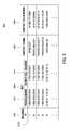
- FIG. 5is a diagram depicting a phonebook 500 according to some embodiments of the invention.
- the phonebook 500has a format defined by a record column 502 , a key column 504 , a contact name column 506 , and a contact number column 508 .
- the key column 504includes a from number column 512 and a direct dial number column 514 .
- the phonebook 500includes a plurality of entries 510 . Each entry includes a record number in the record column 502 , a telephone number in the from number column 512 , a telephone number in the direct dial number column 514 , a name in the contact name column 506 , and a telephone number in the contact number column 508 .
- Each entry 510essentially maps a direct dial number to a contact name and actual telephone number.
- the phonebook 500is merely exemplary and can have other formats for mapping a direct dial number to an actual telephone number.
- FIG. 2is a flow diagram depicting a method 200 of handling caller ID data for an outgoing call according to some embodiments of the invention.
- the method 200may be performed by a gateway server in the VOIP network 103 or any other server.
- the useris the calling party placing a call to a called party.
- the telephone device of the called partycan be attached to the PSTN or to the VOIP network.
- a placed call by a calling partymay also be referred to as a “communication request.”
- the method 200begins at step 202 , where a user dials a direct dial number that is part of a phonebook maintained by the VOIP network.
- a userdials a direct dial number that is part of a phonebook maintained by the VOIP network.
- an actual telephone numberis obtained from the phonebook that is associated with the direct dial number.
- an initial identifieris obtained for the caller ID function associated with the user (e.g., the user's actual telephone number, name, etc).
- a determinationis made whether the user has a relevant virtual telephone number. Notably, the user may have a single virtual telephone number or different virtual telephone numbers for different countries.
- the method 200proceeds to step 206 .
- the caller ID data for the callis configured to include the user's relevant virtual telephone number (the initial identifier is replaced with the virtual telephone number). That is, the called party will see the user's relevant virtual telephone number rather than the user's actual telephone number.
- the caller ID datamay include other information, such as a name associated with the calling party.
- the method 200proceeds to step 208 .
- the predefined telephone numbercan be the user's actual telephone number (i.e., the initial identifier is not changed).
- the VoIP providermay assign the user a telephone number different than the user's actual telephone number (e.g., a default number). This assigned telephone number may be referred to herein as a local personal assigned telephone number.
- the predefined telephone number at step 210may be the user's local personal assigned telephone number.
- the method 200proceeds to step 212 .
- the caller ID data for the callis configured to show the user's corresponding direct dial number as set by the called party in their phonebook (the initial identifier is replaced with the corresponding direct dial number). That is, if the called party has setup a direct dial number for the user (calling party), then this direct dial number is included in the caller ID data when receiving a call from the user (calling party), rather than the user's actual telephone number.
- the method 200first checks if the user has a relevant virtual telephone number and then, in absence of such virtual telephone number, checks whether the called party has direct dial number(s) in a phonebook.
- steps 205 and 208can be switched (i.e., the check at 208 can be performed before the check at 205 ).
- the order of the checks at 205 and 208can be changed based on preferences of the VoIP provider and/or user.
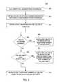
- FIG. 3is a flow diagram depicting a method 300 of handling caller ID data of an incoming call according to some embodiments of the invention.
- the method 300may be performed by a gateway server in the VOIP network 103 or any other server.
- the useris the called party receiving a call from a calling party.
- the telephone device of the calling partycan be attached to the PSTN or to the VOIP network.
- the method 300begins at step 302 , where a calling party dials a virtual telephone number of a user of the VOIP network.
- the callis received by the VOIP network (e.g., by a gateway server or other server).
- an actual telephone numberis obtained for the virtual telephone number.
- an initial identifieris obtained for the caller ID function (e.g., an actual telephone number of the calling party).
- a determinationis made whether the calling party has a relevant virtual telephone number. If so, the method 300 proceeds to step 310 , where the caller ID data is configured to include the relevant virtual telephone number of the calling party (the initial identifier is replaced with the virtual telephone number). That is, the user (called party) sees the relevant virtual number of the calling party, rather than the actual telephone number of the calling party.
- step 312a determination is made whether the user has a direct dial phonebook setup with the VOIP network. If not, the method 300 proceeds to step 314 , where the caller ID data is configured to include a predefined telephone number.
- the predefined telephone numberis the calling party's actual telephone number. In other embodiments, the predefined telephone number may be a number assigned to the calling party by the VoIP provider or other service provider that is other than the actual telephone number (e.g., a default number).
- step 312the user has a direct dial phonebook setup
- the method 300proceeds to step 316 .
- step 316a determination is made whether the calling party is in the user's direct dial phonebook. If not, the method 300 proceeds to step 318 , where a direct dial number can be auto-generated for the calling party's actual telephone number and included in the caller ID data displayed the user (the initial identifier is replaced with the auto-generated number). If the user's phonebook includes an entry for the calling party's telephone number, the method proceeds from step 316 to step 320 .
- the caller ID datais configured to include the direct dial number that matches the calling party's telephone number (the initial identifier is replaced with the direct dial number).
- the method 300first checks if the calling party has a relevant virtual telephone number and then, in absence of such virtual telephone number, checks whether the user has direct dial number(s) in a phonebook.
- steps 308 and 312 - 320can be switched (i.e., the steps 312 - 320 can be performed before the check at 308 ).
- the order of the checks at 308 and 312can be changed based on preferences of the VoIP provider and/or user.
- FIG. 4is a block diagram depicting an exemplary embodiment of a computer 400 in accordance with one or more aspects of the invention.
- the computer 400 or multiple ones of the computer 400may be used to implement the any of the servers and/or methods described herein.
- the computer 400may be one of any form of a general purpose computer used in accessing and operating within an IP-based network.
- the computer 400may include a processor 401 , a memory 403 , various support circuits 404 , and an I/O interface 402 .
- the processor 401may include one or more microprocessors or the like known in the art.
- the support circuits 404include conventional cache, power supplies, clock circuits, data registers, and the like.
- the I/O interface 402is configured for communication with the VOIP network 103 .
- the memory 403 , or computer readable mediummay include one or more of the following random access memory, read only memory, magneto-resistive read/write memory, optical read/write memory, cache memory, magnetic
- the memory 403may store software 450 that is executed to perform methods of according to embodiments of the invention.
- the software 450can implement at least a portion of the methods 200 and 300 performed by a gateway server or other server in the VOIP network 103 .
- the software 450when executed by the processor 401 , transforms the general purpose computer into a specific purpose computer that controls methods described herein.
- embodiments of the process of the present inventionare discussed as being implemented as a software routine, some of the method steps that are disclosed herein may be performed in hardware or a combination of hardware and software.
- the inventionmay be implemented in software as executed upon a computer system, in hardware as an application specific integrated circuit or other type of hardware implementation, or a combination of software and hardware.
- the software 450may act as a “stand alone” program or may be embedded with one or more other routines or programs that provide one or more additional telecommunication services.
- the software 450 of the present inventionis capable of being executed on computer operating systems including but not limited to Microsoft Windows 98, Microsoft Windows XP, Apple OS X and Linux.
- the software 450 of the present inventionis capable of being performed using CPU architectures including but not limited to Apple Power PC, AMD/Intel ⁇ 86, Sun SPARC, and Intel ARM.
Landscapes
- Engineering & Computer Science (AREA)
- Signal Processing (AREA)
- Computer Networks & Wireless Communication (AREA)
- Telephonic Communication Services (AREA)
Abstract
Description
Claims (17)
Priority Applications (1)
| Application Number | Priority Date | Filing Date | Title |
|---|---|---|---|
| US13/289,563US8588387B2 (en) | 2009-10-05 | 2011-11-04 | Method and apparatus for providing an identifier for a caller ID function in a telecommunication system |
Applications Claiming Priority (3)
| Application Number | Priority Date | Filing Date | Title |
|---|---|---|---|
| US24874009P | 2009-10-05 | 2009-10-05 | |
| US12/897,405US8064582B2 (en) | 2009-10-05 | 2010-10-04 | Method and apparatus for providing an identifier for a caller ID function in a telecommunication system |
| US13/289,563US8588387B2 (en) | 2009-10-05 | 2011-11-04 | Method and apparatus for providing an identifier for a caller ID function in a telecommunication system |
Related Parent Applications (1)
| Application Number | Title | Priority Date | Filing Date |
|---|---|---|---|
| US12/897,405ContinuationUS8064582B2 (en) | 2009-10-05 | 2010-10-04 | Method and apparatus for providing an identifier for a caller ID function in a telecommunication system |
Publications (2)
| Publication Number | Publication Date |
|---|---|
| US20120051267A1 US20120051267A1 (en) | 2012-03-01 |
| US8588387B2true US8588387B2 (en) | 2013-11-19 |
Family
ID=43823176
Family Applications (2)
| Application Number | Title | Priority Date | Filing Date |
|---|---|---|---|
| US12/897,405ActiveUS8064582B2 (en) | 2009-10-05 | 2010-10-04 | Method and apparatus for providing an identifier for a caller ID function in a telecommunication system |
| US13/289,563Active2030-12-23US8588387B2 (en) | 2009-10-05 | 2011-11-04 | Method and apparatus for providing an identifier for a caller ID function in a telecommunication system |
Family Applications Before (1)
| Application Number | Title | Priority Date | Filing Date |
|---|---|---|---|
| US12/897,405ActiveUS8064582B2 (en) | 2009-10-05 | 2010-10-04 | Method and apparatus for providing an identifier for a caller ID function in a telecommunication system |
Country Status (6)
| Country | Link |
|---|---|
| US (2) | US8064582B2 (en) |
| EP (1) | EP2486709A4 (en) |
| CA (1) | CA2775592A1 (en) |
| IL (2) | IL218690A (en) |
| MX (1) | MX2012003649A (en) |
| WO (1) | WO2011044041A2 (en) |
Cited By (10)
| Publication number | Priority date | Publication date | Assignee | Title |
|---|---|---|---|---|
| US20130295899A1 (en)* | 2012-05-07 | 2013-11-07 | Philip Lowman | System and Method for Provision of a Second Line Service to a Telecommunications Device |
| US20160088162A1 (en)* | 2014-09-19 | 2016-03-24 | Vonage Network Llc | Method and systems for automatically assigning virtual numbers |
| US9521112B2 (en) | 2013-09-16 | 2016-12-13 | Vonage America Inc. | Systems and methods of assigning and using virtual telephone numbers |
| US10009387B2 (en) | 2013-09-16 | 2018-06-26 | Vonage America Inc. | Systems and methods of assigning and using virtual telephone numbers |
| US10097685B2 (en) | 2015-07-05 | 2018-10-09 | Roger Sauln | Telecommunications privacy method |
| US10477013B1 (en)* | 2018-11-19 | 2019-11-12 | Successful Cultures, Inc | Systems and methods for providing caller identification over a public switched telephone network |
| US11968330B1 (en) | 2018-11-19 | 2024-04-23 | Successful Cultures, Inc. | Systems and methods for providing caller identification over a public switched telephone network |
| US12101441B1 (en) | 2018-11-19 | 2024-09-24 | Successful Cultures, Inc. | Systems and methods for providing caller identification over a public switched telephone network |
| US12126767B1 (en) | 2018-11-19 | 2024-10-22 | Successful Cultures, Inc. | Systems and methods for providing caller identification over a publicswitched telephone network |
| US12267458B1 (en) | 2018-11-19 | 2025-04-01 | Successful Cultures, Inc. | Systems and methods for call placement over a public switched telephone network |
Families Citing this family (23)
| Publication number | Priority date | Publication date | Assignee | Title |
|---|---|---|---|---|
| CA2648184C (en)* | 2007-12-28 | 2014-07-08 | Bce Inc. | Method and apparatus for conveying a calling party identifier |
| US11082548B2 (en)* | 2008-06-05 | 2021-08-03 | Movius Interactive Corporation | System and method for providing a pre-populated second line service to a telecommunications device |
| US9332425B2 (en)* | 2012-05-07 | 2016-05-03 | Movius Interactive Corporation | System and method for provision of a second line service to a telecommunications device using mixed protocols |
| US20150271774A1 (en)* | 2008-06-05 | 2015-09-24 | George Backhaus | System and method for provision of a local second line service to a roaming telecommunications device using mixed protocols |
| US9967797B2 (en)* | 2008-06-05 | 2018-05-08 | Movius Interactive Corp | System and method for provision of a second line service to a telecommunications device using mixed relationship numbers |
| CN101404684B (en)* | 2008-11-10 | 2012-05-23 | 中兴通讯股份有限公司 | System and method for displaying user alias |
| MX2013013965A (en) | 2011-05-31 | 2014-04-14 | World Emergency Networ Nevada Ltd | Mobile phone as a one-way recorded transmitter over a cellular network. |
| US8824652B2 (en) | 2011-10-12 | 2014-09-02 | World Emergency Network - Nevada, Ltd. | Controlled recorded 3-way calling |
| CA2839952C (en) | 2011-06-30 | 2018-03-27 | World Emergency Network - Nevada, Ltd. | Attaching multiple phone lines to a single mobile or landline phone |
| US9998603B2 (en) | 2011-06-30 | 2018-06-12 | World Emergency Network—Nevada, Ltd. | Attaching multiple phone lines to a single mobile or landline phone |
| US8599837B2 (en)* | 2011-11-18 | 2013-12-03 | Verizon Patent And Licensing Inc. | Local identity based on called number |
| US8306201B1 (en)* | 2012-04-02 | 2012-11-06 | MagicJack Vocaltec Ltd. | Telephone number sharing configuration |
| US9060057B1 (en)* | 2013-03-07 | 2015-06-16 | Serdar Artun Danis | Systems and methods for caller ID authentication, spoof detection and list based call handling |
| US9332119B1 (en)* | 2013-03-07 | 2016-05-03 | Serdar Artun Danis | Systems and methods for call destination authenticaiton and call forwarding detection |
| US10447837B2 (en) | 2015-04-15 | 2019-10-15 | World Emergency Network—Nevada, Ltd. | International one-way recorded transmitter over a cellular network |
| US20170034357A1 (en)* | 2015-07-30 | 2017-02-02 | PassportPhone LLC | Systems and Methods for Making Low-Cost International Phone Calls |
| WO2017172807A1 (en) | 2016-03-30 | 2017-10-05 | World Emergency Network-Nevada, Ltd. | Virtual numbers for intelligence operations |
| US11605100B1 (en) | 2017-12-22 | 2023-03-14 | Salesloft, Inc. | Methods and systems for determining cadences |
| US11115624B1 (en) | 2019-07-22 | 2021-09-07 | Salesloft, Inc. | Methods and systems for joining a conference |
| US10742695B1 (en) | 2018-08-01 | 2020-08-11 | Salesloft, Inc. | Methods and systems of recording information related to an electronic conference system |
| US10791217B1 (en)* | 2019-09-03 | 2020-09-29 | Salesloft, Inc. | Methods and systems for placing calls |
| US11586878B1 (en) | 2021-12-10 | 2023-02-21 | Salesloft, Inc. | Methods and systems for cascading model architecture for providing information on reply emails |
| JP7582696B2 (en) | 2023-02-16 | 2024-11-13 | Necプラットフォームズ株式会社 | Telephone device, caller number notification method and program |
Citations (11)
| Publication number | Priority date | Publication date | Assignee | Title |
|---|---|---|---|---|
| US20030147518A1 (en)* | 1999-06-30 | 2003-08-07 | Nandakishore A. Albal | Methods and apparatus to deliver caller identification information |
| US6662006B2 (en)* | 1997-12-16 | 2003-12-09 | At&T Wireless Services, Inc. | Method and apparatus for providing calling number identification alias in communications system |
| US20060188084A1 (en)* | 1996-03-11 | 2006-08-24 | Aspect Communications Corporation | Call management system with call control from user workstation computers |
| US20070003036A1 (en)* | 2005-06-28 | 2007-01-04 | International Business Machines Corporation | Identifying a caller who uses an unrecognized terminal |
| KR100706486B1 (en) | 2005-10-19 | 2007-04-10 | 주식회사 케이티프리텔 | Method and system for converting outgoing number using intelligent network |
| US20070105531A1 (en) | 2005-11-04 | 2007-05-10 | Ascenna Mobile, Inc. | Dynamic Processing of Virtual Identities for Mobile Communications Devices |
| US7346156B1 (en) | 2004-01-29 | 2008-03-18 | Stanacard Llc | Methods and apparatuses for placing a telephone call |
| US20080159501A1 (en)* | 2006-12-29 | 2008-07-03 | Yigang Cai | Validating caller id information to protect against caller id spoofing |
| KR20080084198A (en) | 2007-03-15 | 2008-09-19 | (주)제너시스템즈 | Telephony communication method and device using internet-capable media |
| US7734026B2 (en)* | 2005-12-29 | 2010-06-08 | At&T Intellectual Property I, L.P. | User selected caller ID override |
| US20100303219A1 (en)* | 2009-05-28 | 2010-12-02 | Avaya Inc. | Method for including caller-provided subject information in the caller-id display of enterprise telephones |
Family Cites Families (7)
| Publication number | Priority date | Publication date | Assignee | Title |
|---|---|---|---|---|
| US5274699A (en)* | 1992-07-24 | 1993-12-28 | Motorola, Inc. | Method for providing caller identification to a call recipient |
| US5590184A (en)* | 1995-03-03 | 1996-12-31 | Lucent Technologies Inc. | Communications privacy protection system by replacing calling party number with non-assigned number |
| US5796791A (en)* | 1996-10-15 | 1998-08-18 | Intervoice Limited Partnership | Network based predictive dialing |
| US7103162B1 (en)* | 2002-08-12 | 2006-09-05 | Bellsouth Intellectual Property Corp. | Exempting certain incoming callers from screening by a privacy system |
| US7551731B2 (en)* | 2004-08-31 | 2009-06-23 | Alcatel-Lucent Usa Inc. | Flexible caller ID and calling name information presentation |
| US20070064895A1 (en)* | 2005-09-09 | 2007-03-22 | Wong Daniel H | System and method for telephone call information aliasing |
| WO2007056577A2 (en)* | 2005-11-09 | 2007-05-18 | Vonage Holdings Corp. | Method and system for customized caller identification |
- 2010
- 2010-10-04WOPCT/US2010/051320patent/WO2011044041A2/enactiveApplication Filing
- 2010-10-04MXMX2012003649Apatent/MX2012003649A/enactiveIP Right Grant
- 2010-10-04EPEP10822479.1Apatent/EP2486709A4/ennot_activeWithdrawn
- 2010-10-04USUS12/897,405patent/US8064582B2/enactiveActive
- 2010-10-04CACA2775592Apatent/CA2775592A1/ennot_activeAbandoned
- 2011
- 2011-11-04USUS13/289,563patent/US8588387B2/enactiveActive
- 2012
- 2012-03-15ILIL218690Apatent/IL218690A/ennot_activeIP Right Cessation
- 2015
- 2015-01-22ILIL236867Apatent/IL236867A0/enunknown
Patent Citations (11)
| Publication number | Priority date | Publication date | Assignee | Title |
|---|---|---|---|---|
| US20060188084A1 (en)* | 1996-03-11 | 2006-08-24 | Aspect Communications Corporation | Call management system with call control from user workstation computers |
| US6662006B2 (en)* | 1997-12-16 | 2003-12-09 | At&T Wireless Services, Inc. | Method and apparatus for providing calling number identification alias in communications system |
| US20030147518A1 (en)* | 1999-06-30 | 2003-08-07 | Nandakishore A. Albal | Methods and apparatus to deliver caller identification information |
| US7346156B1 (en) | 2004-01-29 | 2008-03-18 | Stanacard Llc | Methods and apparatuses for placing a telephone call |
| US20070003036A1 (en)* | 2005-06-28 | 2007-01-04 | International Business Machines Corporation | Identifying a caller who uses an unrecognized terminal |
| KR100706486B1 (en) | 2005-10-19 | 2007-04-10 | 주식회사 케이티프리텔 | Method and system for converting outgoing number using intelligent network |
| US20070105531A1 (en) | 2005-11-04 | 2007-05-10 | Ascenna Mobile, Inc. | Dynamic Processing of Virtual Identities for Mobile Communications Devices |
| US7734026B2 (en)* | 2005-12-29 | 2010-06-08 | At&T Intellectual Property I, L.P. | User selected caller ID override |
| US20080159501A1 (en)* | 2006-12-29 | 2008-07-03 | Yigang Cai | Validating caller id information to protect against caller id spoofing |
| KR20080084198A (en) | 2007-03-15 | 2008-09-19 | (주)제너시스템즈 | Telephony communication method and device using internet-capable media |
| US20100303219A1 (en)* | 2009-05-28 | 2010-12-02 | Avaya Inc. | Method for including caller-provided subject information in the caller-id display of enterprise telephones |
Non-Patent Citations (1)
| Title |
|---|
| International Search Report and Written Opinion dated Jun. 16, 2011 for PCT Application No. PCT/US2010/051320. |
Cited By (12)
| Publication number | Priority date | Publication date | Assignee | Title |
|---|---|---|---|---|
| US20130295899A1 (en)* | 2012-05-07 | 2013-11-07 | Philip Lowman | System and Method for Provision of a Second Line Service to a Telecommunications Device |
| US9332408B2 (en)* | 2012-05-07 | 2016-05-03 | Movius Interactive Corporation | System and method for provision of a second line service to a telecommunications device |
| US9521112B2 (en) | 2013-09-16 | 2016-12-13 | Vonage America Inc. | Systems and methods of assigning and using virtual telephone numbers |
| US10009387B2 (en) | 2013-09-16 | 2018-06-26 | Vonage America Inc. | Systems and methods of assigning and using virtual telephone numbers |
| US20160088162A1 (en)* | 2014-09-19 | 2016-03-24 | Vonage Network Llc | Method and systems for automatically assigning virtual numbers |
| US9712682B2 (en)* | 2014-09-19 | 2017-07-18 | Vonage America Inc. | Method and systems for automatically assigning virtual numbers |
| US10097685B2 (en) | 2015-07-05 | 2018-10-09 | Roger Sauln | Telecommunications privacy method |
| US10477013B1 (en)* | 2018-11-19 | 2019-11-12 | Successful Cultures, Inc | Systems and methods for providing caller identification over a public switched telephone network |
| US11968330B1 (en) | 2018-11-19 | 2024-04-23 | Successful Cultures, Inc. | Systems and methods for providing caller identification over a public switched telephone network |
| US12101441B1 (en) | 2018-11-19 | 2024-09-24 | Successful Cultures, Inc. | Systems and methods for providing caller identification over a public switched telephone network |
| US12126767B1 (en) | 2018-11-19 | 2024-10-22 | Successful Cultures, Inc. | Systems and methods for providing caller identification over a publicswitched telephone network |
| US12267458B1 (en) | 2018-11-19 | 2025-04-01 | Successful Cultures, Inc. | Systems and methods for call placement over a public switched telephone network |
Also Published As
| Publication number | Publication date |
|---|---|
| EP2486709A4 (en) | 2014-08-06 |
| US8064582B2 (en) | 2011-11-22 |
| US20120051267A1 (en) | 2012-03-01 |
| IL236867A0 (en) | 2015-03-31 |
| IL218690A0 (en) | 2012-05-31 |
| WO2011044041A3 (en) | 2011-08-04 |
| CA2775592A1 (en) | 2011-04-14 |
| EP2486709A2 (en) | 2012-08-15 |
| US20110081009A1 (en) | 2011-04-07 |
| WO2011044041A2 (en) | 2011-04-14 |
| MX2012003649A (en) | 2012-05-08 |
| IL218690A (en) | 2015-11-30 |
Similar Documents
| Publication | Publication Date | Title |
|---|---|---|
| US8588387B2 (en) | Method and apparatus for providing an identifier for a caller ID function in a telecommunication system | |
| US11172064B2 (en) | Emergency assistance calling for voice over IP communications systems | |
| US7907718B2 (en) | VoIP call routing | |
| US8639225B2 (en) | E-mail to phone number resolution for mobile to mobile, mobile to landline, and PC to mobile communications | |
| US20100226362A1 (en) | Intelligent Call Mapping and Routing for Low Cost Global Calling on Mobile Devices Including SmartPhones | |
| US8787544B2 (en) | Internet protocol for IP private branch exchanges | |
| CA2647920C (en) | Method and system for routing telephony communications together with modified calling party identifier information | |
| US8064876B2 (en) | Systems for use with multi-number cellular devices | |
| US8180045B2 (en) | Method for selection and routing of an inbound voice call to an appropriate network for completion | |
| US8467513B2 (en) | Method for selection and routing of an outbound voice call to an appropriate network for completion | |
| JP5351765B2 (en) | Method and apparatus for linking identification data to calls between networks | |
| US20080293427A1 (en) | System and method for mobile originated optimal call routing | |
| US20080292092A1 (en) | System and method for telephone number normalization and denormalization | |
| US20080130632A1 (en) | Apparatus and method for making calls via internet | |
| US9667802B2 (en) | Methods of assigning, recording and using a location routing number | |
| US7839992B2 (en) | Method and apparatus for registering multiple phone numbers associated with a frequently called party | |
| EP2410724A1 (en) | Method and system for communication forwarding | |
| US20100290455A1 (en) | Method and apparatus for communication request termination routing | |
| US7916846B1 (en) | System and method for identifying and treating calls | |
| US8681960B2 (en) | Extending originating capabilities of a subscriber to devices in any telephony network | |
| EP1111893A2 (en) | Private reuse of the public switched telephone network dial plan | |
| US20070105537A1 (en) | Network support for remote caller ID information | |
| RU2582066C2 (en) | Method and system for info communication |
Legal Events
| Date | Code | Title | Description |
|---|---|---|---|
| AS | Assignment | Owner name:VONAGE NETWORK LLC, NEW JERSEY Free format text:ASSIGNMENT OF ASSIGNORS INTEREST;ASSIGNORS:MA, KEVIN;WILTON, ARTHUR;VILLANI, PASQUALE;AND OTHERS;SIGNING DATES FROM 20101108 TO 20101203;REEL/FRAME:027184/0909 | |
| AS | Assignment | Owner name:JPMORGAN CHASE BANK, N.A., AS ADMINISTRATIVE AGENT, ILLINOIS Free format text:SECURITY AGREEMENT;ASSIGNOR:VONAGE NETWORK LLC;REEL/FRAME:028194/0597 Effective date:20120510 Owner name:JPMORGAN CHASE BANK, N.A., AS ADMINISTRATIVE AGENT Free format text:SECURITY AGREEMENT;ASSIGNOR:VONAGE NETWORK LLC;REEL/FRAME:028194/0597 Effective date:20120510 | |
| STCF | Information on status: patent grant | Free format text:PATENTED CASE | |
| AS | Assignment | Owner name:JPMORGAN CHASE BANK, N.A., AS ADMINISTRATIVE AGENT, ILLINOIS Free format text:SECURITY INTEREST;ASSIGNORS:VONAGE HOLDINGS CORP.;VONAGE NETWORK LLC;VONAGE BUSINESS SOLUTIONS INC.;AND OTHERS;REEL/FRAME:033545/0424 Effective date:20140813 Owner name:JPMORGAN CHASE BANK, N.A., AS ADMINISTRATIVE AGENT Free format text:SECURITY INTEREST;ASSIGNORS:VONAGE HOLDINGS CORP.;VONAGE NETWORK LLC;VONAGE BUSINESS SOLUTIONS INC.;AND OTHERS;REEL/FRAME:033545/0424 Effective date:20140813 | |
| AS | Assignment | Owner name:JPMORGAN CHASE BANK, N.A., AS ADMINISTRATIVE AGENT, ILLINOIS Free format text:SECURITY INTEREST;ASSIGNORS:VONAGE HOLDINGS CORP.;VONAGE AMERICA INC.;VONAGE BUSINESS SOLUTIONS, INC.;AND OTHERS;REEL/FRAME:036205/0485 Effective date:20150727 Owner name:JPMORGAN CHASE BANK, N.A., AS ADMINISTRATIVE AGENT Free format text:SECURITY INTEREST;ASSIGNORS:VONAGE HOLDINGS CORP.;VONAGE AMERICA INC.;VONAGE BUSINESS SOLUTIONS, INC.;AND OTHERS;REEL/FRAME:036205/0485 Effective date:20150727 | |
| AS | Assignment | Owner name:JPMORGAN CHASE BANK, N.A., AS ADMINISTRATIVE AGENT, ILLINOIS Free format text:CORRECTIVE ASSIGNMENT TO CORRECT THE PATENT APPLICATION NUMBER 13966486 PREVIOUSLY RECORDED ON REEL 033545 FRAME 0424. ASSIGNOR(S) HEREBY CONFIRMS THE SECURITY INTEREST;ASSIGNORS:VONAGE HOLDINGS CORP.;VONAGE NETWORK LLC;VONAGE BUSINESS SOLUTIONS INC.;AND OTHERS;REEL/FRAME:037570/0203 Effective date:20140813 Owner name:JPMORGAN CHASE BANK, N.A., AS ADMINISTRATIVE AGENT Free format text:CORRECTIVE ASSIGNMENT TO CORRECT THE PATENT APPLICATION NUMBER 13966486 PREVIOUSLY RECORDED ON REEL 033545 FRAME 0424. ASSIGNOR(S) HEREBY CONFIRMS THE SECURITY INTEREST;ASSIGNORS:VONAGE HOLDINGS CORP.;VONAGE NETWORK LLC;VONAGE BUSINESS SOLUTIONS INC.;AND OTHERS;REEL/FRAME:037570/0203 Effective date:20140813 | |
| AS | Assignment | Owner name:VONAGE BUSINESS INC., GEORGIA Free format text:ASSIGNMENT OF ASSIGNORS INTEREST;ASSIGNOR:VONAGE NETWORK LLC;REEL/FRAME:038328/0501 Effective date:20160304 | |
| AS | Assignment | Owner name:VONAGE BUSINESS INC., GEORGIA Free format text:CORRECTIVE ASSIGNMENT TO CORRECT THE LIST BY DELETING 13831728 13831785 14291602 13680382 14827548 14752086 13680067 14169385 14473289 14194220 14194438 14317743 PREVIOUSLY RECORDED ON REEL 038328 FRAME 501. ASSIGNOR(S) HEREBY CONFIRMS THE SALE, ASSIGNMENT, TRANSFER AND CONVEYANCE OF REMAINING PROPERTIES;ASSIGNOR:VONAGE NETWORK LLC;REEL/FRAME:040540/0702 Effective date:20160304 | |
| FPAY | Fee payment | Year of fee payment:4 | |
| AS | Assignment | Owner name:JPMORGAN CHASE BANK, N.A., AS ADMINISTRATIVE AGENT, ILLINOIS Free format text:SECURITY INTEREST;ASSIGNOR:VONAGE BUSINESS INC.;REEL/FRAME:047502/0432 Effective date:20181106 Owner name:JPMORGAN CHASE BANK, N.A., AS ADMINISTRATIVE AGENT Free format text:SECURITY INTEREST;ASSIGNOR:VONAGE BUSINESS INC.;REEL/FRAME:047502/0432 Effective date:20181106 | |
| MAFP | Maintenance fee payment | Free format text:PAYMENT OF MAINTENANCE FEE, 8TH YEAR, LARGE ENTITY (ORIGINAL EVENT CODE: M1552); ENTITY STATUS OF PATENT OWNER: LARGE ENTITY Year of fee payment:8 | |
| AS | Assignment | Owner name:TOKBOX, INC., NEW JERSEY Free format text:RELEASE BY SECURED PARTY;ASSIGNOR:JPMORGAN CHASE BANK, N.A.;REEL/FRAME:061002/0340 Effective date:20220721 Owner name:NEXMO INC., NEW JERSEY Free format text:RELEASE BY SECURED PARTY;ASSIGNOR:JPMORGAN CHASE BANK, N.A.;REEL/FRAME:061002/0340 Effective date:20220721 Owner name:VONAGE BUSINESS INC., NEW JERSEY Free format text:RELEASE BY SECURED PARTY;ASSIGNOR:JPMORGAN CHASE BANK, N.A.;REEL/FRAME:061002/0340 Effective date:20220721 Owner name:VONAGE HOLDINGS CORP., NEW JERSEY Free format text:RELEASE BY SECURED PARTY;ASSIGNOR:JPMORGAN CHASE BANK, N.A.;REEL/FRAME:061002/0340 Effective date:20220721 Owner name:VONAGE AMERICA INC., NEW JERSEY Free format text:RELEASE BY SECURED PARTY;ASSIGNOR:JPMORGAN CHASE BANK, N.A.;REEL/FRAME:061002/0340 Effective date:20220721 | |
| MAFP | Maintenance fee payment | Free format text:PAYMENT OF MAINTENANCE FEE, 12TH YEAR, LARGE ENTITY (ORIGINAL EVENT CODE: M1553); ENTITY STATUS OF PATENT OWNER: LARGE ENTITY Year of fee payment:12 |