US8588156B1 - Direct data communication in infrastructure mode in wireless communication systems - Google Patents
Direct data communication in infrastructure mode in wireless communication systemsDownload PDFInfo
- Publication number
- US8588156B1 US8588156B1US12/768,434US76843410AUS8588156B1US 8588156 B1US8588156 B1US 8588156B1US 76843410 AUS76843410 AUS 76843410AUS 8588156 B1US8588156 B1US 8588156B1
- Authority
- US
- United States
- Prior art keywords
- wireless network
- network device
- data frame
- determining
- directly transmitted
- Prior art date
- Legal status (The legal status is an assumption and is not a legal conclusion. Google has not performed a legal analysis and makes no representation as to the accuracy of the status listed.)
- Expired - Fee Related, expires
Links
Images


Classifications
- H04W76/023—
- H—ELECTRICITY
- H04—ELECTRIC COMMUNICATION TECHNIQUE
- H04W—WIRELESS COMMUNICATION NETWORKS
- H04W76/00—Connection management
- H04W76/10—Connection setup
- H04W76/14—Direct-mode setup
- H—ELECTRICITY
- H04—ELECTRIC COMMUNICATION TECHNIQUE
- H04W—WIRELESS COMMUNICATION NETWORKS
- H04W36/00—Hand-off or reselection arrangements
- H04W36/0005—Control or signalling for completing the hand-off
- H04W36/0011—Control or signalling for completing the hand-off for data sessions of end-to-end connection
- H04W36/0022—Control or signalling for completing the hand-off for data sessions of end-to-end connection for transferring data sessions between adjacent core network technologies
- H—ELECTRICITY
- H04—ELECTRIC COMMUNICATION TECHNIQUE
- H04W—WIRELESS COMMUNICATION NETWORKS
- H04W84/00—Network topologies
- H04W84/02—Hierarchically pre-organised networks, e.g. paging networks, cellular networks, WLAN [Wireless Local Area Network] or WLL [Wireless Local Loop]
- H04W84/10—Small scale networks; Flat hierarchical networks
- H04W84/12—WLAN [Wireless Local Area Networks]
Definitions
- Embodiments of the inventive subject mattergenerally relate to the field of wireless communication and, more particularly, to direct data communication in an infrastructure mode in wireless communication systems.
- An infrastructure mode in a wireless local area network (WLAN)(“infrastructure WLAN”) provides a mechanism for WLAN devices to communicate with each other via a centralized connection point (i.e., an access point).
- a source WLAN deviceFor a source WLAN device to communicate with a destination WLAN device in the infrastructure WLAN, the source WLAN device first transmits data frames to the access point. The access point then transmits the received data frames to the destination WLAN device.
- Various embodiments for implementing direct data communication in an infrastructure mode in wireless communication systemsare disclosed.
- itis determined at a first wireless network device of a wireless communication network operating in an infrastructure mode, that a data frame is scheduled to be transmitted from the first wireless network device to a second wireless device of the wireless communication network.
- itis determined whether the data frame can be directly transmitted to the second wireless network device based on connection information received in a beacon frame from an access point of the wireless communication network.
- the connection informationcomprises an indication of whether data frames can be directly transmitted to the second wireless network device.
- the data frameis directly transmitted to the second wireless network device, in response to determining that the data frame can be directly transmitted from the first wireless network device to the second wireless network device.
- the data frameis transmitted to the access point for transmission to the second wireless network device via the access point, in response to determining that the data frame cannot be directly transmitted from the first wireless network device to the second wireless network device.
- FIG. 1is a conceptual diagram illustrating example operations for direct data transmission in an infrastructure wireless system
- FIG. 2Aillustrates an example format of a connected devices field for communicating connection information associated with the WLAN devices in the BSS;
- FIG. 2Billustrates an example format of a data frame that is transmitted to the destination WLAN device
- FIG. 3is a flow diagram illustrating example operations at a source WLAN device for determining whether data frames can be directly transmitted to a destination WLAN device;
- FIG. 4is a flow diagram illustrating example operations at a destination WLAN device for updating information indicating whether data frames can be directly transmitted to a source WLAN device;
- FIG. 5is a block diagram of one embodiment of an electronic device including a mechanism for direct data communication in an infrastructure WLAN.
- Typical operations for data communication in an infrastructure WLANinvolve a source WLAN device transmitting a data frame to a destination WLAN device via an access point.
- the source WLAN devicetransmits the data frame to the access point, which, in turn, transmits the data frame to the destination WLAN device.
- communication between the source WLAN device and the destination WLAN deviceinvolves at least two transmissions of the same data frame. This results in an increase in transmission overhead and consequently results in transmission inefficiency.
- the access point in the infrastructure WLANcan be configured to transmit a beacon frame to notify each WLAN device of the other WLAN devices in the infrastructure WLAN.
- the access pointcan broadcast device identifiers of the WLAN devices in the infrastructure WLAN and an indication of whether the WLAN devices can directly receive the data frames (i.e., without transmission via the access point).
- a source WLAN devicecan determine whether a destination WLAN device can directly receive data frames. If so, the source WLAN device can directly transmit the data frames to the destination WLAN device without having to transmit the data frames to the access point.
- Such a direct data communication between WLAN devices in the infrastructure WLANcan reduce transmission overhead and can also improve transmission efficiency.
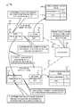
- FIG. 1is a conceptual diagram illustrating example operations for direct data transmission in an infrastructure WLAN.
- FIG. 1depicts an access point 102 , a WLAN device 104 , and a WLAN device 110 .
- the WLAN device 104wirelessly connects to communicate with the access point 102 as depicted by a dashed line 150 between the WLAN device 104 and the access point 102 .
- the WLAN device 110also wirelessly connects to communicate with the access point 102 as depicted by a dashed line 152 between the WLAN device 110 and the access point 102 .
- the access point 102 , the WLAN device 104 , and the WLAN device 110together are part of a basic service set (BSS) 100 in the infrastructure WLAN.
- BSSbasic service set
- the BSSconstitutes an access point and WLAN devices associated with (i.e., connected to) the access point.
- the WLAN devices in one BSScan communicate with each other via the access point.
- the WLAN devices in one BSScan also communicate with WLAN devices in another BSS via their respective access points.
- the WLAN device 104comprises a data communication unit 106 and a network information unit 108 .
- the WLAN device 110comprises a data communication unit 112 and a network information unit 114 .
- the access point 102transmits a beacon frame, at each beacon interval, to update connection information of the WLAN devices 104 and 110 in the BSS 100 .
- the access point 102indicates a device identifier (e.g., a MAC address) of each WLAN device in the BSS 100 , and also indicates whether each WLAN device can directly receive data frames from another WLAN device.
- FIG. 2Aillustrates an example format of a connected devices field 200 in a beacon frame used for broadcasting the connection information associated with the WLAN devices 104 and 110 in the BSS 100 .
- the connected devices field 200comprises a WLAN device address field 202 , a direct connect flag 204 , and reserved fields 206 .
- the WLAN device address field 202can indicate a medium access control (MAC) address of the WLAN device or other suitable network/device identifier that uniquely identifies the WLAN device.
- the direct connect flag 204indicates whether or not the WLAN device can be reached directly by another WLAN device in the BSS 100 .
- the access point 102may transmit a default value of “1” in the direct connect flag 204 to indicate that all the WLAN devices in the BSS 100 can directly receive data frames.
- each WLAN device in the BSS 100may indicate, to the access point 102 , whether it can directly receive the data frames from other WLAN devices.
- the connected devices field 200may not comprise the direct connect flag 204 .
- the WLAN devicesmay initially store a default direct connect value of “1” to indicate the other WLAN devices can directly receive data frames, and then update the direct connect value accordingly based on whether attempts to directly communicate with the WLAN devices are successful.
- the access point 102can transmit the connection information associated with the WLAN devices 104 and 110 connected to the access point 102 in the beacon frame.
- the access point 102may update the beacon frame (e.g., vary the length of the beacon frame, etc.) based on a number of WLAN devices connected to the access point 102 .
- existing reserved fields in the beacon frame(not shown) may be used to transmit the connection information associated with the WLAN devices in the BSS 100 .
- one or more connected devices fields 200may be appended to legacy beacon frame formats to indicate the connection information associated with the WLAN devices 104 and 110 .
- one connected devices field 200may be allocated for each WLAN device in the BSS 100 .
- the BSS 100comprises two WLAN devices
- two connected devices fields 200may be appended to the legacy beacon frame.
- the first connected device field 200may indicate the connection information associated with the first WLAN device and the second connected device field 200 may indicate the connection information associated with the second WLAN device.
- Each WLAN device in the BSS 100can receive the beacon frame, read the connected devices field 200 , and can store the connection information associated with each of the other WLAN devices in the BSS 100 .
- the WLAN device 104may determine and store the connection information associated with the WLAN device 110 .
- the BSS 100may include other WLAN devices in addition to the WLAN devices 104 and 110 .
- the data communication unit 106 in a source WLAN device 104determines that a data frame is scheduled to be transmitted to a destination WLAN device 110 .
- the data communication unit 106may access a transmit data buffer (not shown) to determine that the data frame is scheduled to be transmitted to the destination WLAN device 110 .
- the data communication unit 106may also determine that the device identifier of the destination WLAN device 110 is 0x00.
- the data communication unit 106determines that a direct connect flag associated with the destination WLAN device 110 is set to “1”.
- the direct connect flagcan indicate whether the WLAN device associated with the direct connect flag can be reached directly (i.e., whether data frames can be directly transmitted to the WLAN device).
- the data communication unit 106may query the network information unit 108 to determine the status of the direct connect flag associated with the destination WLAN device 110 .
- the data communication unit 106may provide the device identifier (e.g., 0x00) of the destination WLAN device 110 to the network information unit 108 .
- the network information unit 108can access a connection information table 109 (or other suitable data structure) and can identify an entry 110 corresponding to the device identifier of the destination WLAN device 110 in the connection information table.
- the network information unit 108can determine, and accordingly notify the data communication unit 106 , that the direct connect flag associated with the destination WLAN device 110 is set to “1”.
- the direct connect flag associated with the destination WLAN device 110 being set to “1”can indicate that the source WLAN device 104 can directly transmit the data frame to the destination WLAN device 110 .
- the network information unit 108can determine whether the destination WLAN device 110 and the source WLAN device 104 belong to the same BSS 100 . If so, the network information unit 108 may access the connection information table 109 and determine whether the direct connect flag associated with the destination WLAN device 110 is set to “1”. Otherwise, the network information unit 108 may indicate to the data communication unit 106 that the data frame cannot be directly transmitted to the destination WLAN device 110 .
- FIG. 2Billustrates an example format of a data frame 250 that is transmitted to the destination WLAN device 110 .
- the data frame 250comprises a frame control field 252 , a first address field 256 , a second address field 258 , a third address field 260 , control fields 262 , and, a frame body 270 .
- the frame control field 252comprises frame control fields 280 , a “To” distribution system (DS) field 284 , and a “From” DS field 286 .
- DSdistribution system
- the frame control fields 280comprises various fields for indicating a transmission protocol (e.g., an 802.11 protocol version), a type of frame being transmitted (e.g., 0000 can be transmitted to indicate a data frame), etc.
- the “To” DS field 284 and the “From” DS field 286respectively, indicate whether the data frame 250 is destined for the distribution system (i.e., the access point 102 ) or transmitted from the distribution system.
- the address fieldstypically indicate the address (e.g., MAC address or other device identifier) of the source WLAN device 104 , the address of the destination WLAN device 110 , an identifier (e.g., a service set identifier or SSID) of the access point 102 , etc.
- a transmission protocole.g., an 802.11 protocol version
- a type of frame being transmittede.g., 0000 can be transmitted to indicate a data frame
- the “To” DS field 284 and the “From” DS field 286respectively
- the data communication unit 106determines that the data frame can be directly transmitted to the destination WLAN device 110 . Therefore, the data communication unit 106 can indicate the address of the destination device 110 (e.g., the device identifier 0x00) in the first address field 256 , the address of the source WLAN device 104 (e.g., the device identifier 0x01) in the second address field 258 , and the identifier of the access point 102 in the third address field 260 . The data communication unit 106 may also set the “To” DS field 284 and the “From” DS field 280 in the frame control field 252 to “0” to indicate that the source WLAN device 104 will directly transmit the data frame to the destination WLAN device 110 .
- the destination device 110e.g., the device identifier 0x00
- the address of the source WLAN device 104e.g., the device identifier 0x01
- the data communication unit 106may also set the “To” DS field 284 and the “From”
- the control fields 262can comprise additional address fields, can indicate quality of service (QoS) information, can indicate communication medium access durations, etc.
- the frame body 270can comprise the information scheduled to be transmitted to the destination WLAN device 110 . It is noted, however, that in other embodiments the data communication unit 106 can be configured to transmit any suitable values in the address fields 256 , 258 , and 260 and in the frame control field 252 to indicate that the data frame is being transmitted directly by the source WLAN device 104 to the destination WLAN device 110 .
- the data frame format 250 depicted in FIG. 2Bis an example. Depending on the type of data to be transmitted, some fields depicted in the data frame 250 may not be used, the data frame 250 may comprise additional fields, and/or the length of the data fields may vary.
- the data communication unit 112 in the destination WLAN device 110receives the data frame from the source WLAN device 104 and determines that the source WLAN device 104 transmitted the data frame directly to the destination WLAN device 110 .
- the data communication unit 112may read the address fields 256 , 258 , and 260 in the received data frame 250 and may determine whether the data frame was transmitted by the access point 102 or by another WLAN device in the BSS 100 .
- the data communication unit 112may determine that second address field 258 indicates the address of the source WLAN device 110 and that the third address field 260 indicates the identifier of the access point 102 . This can serve as an indication that the source WLAN device 104 directly transmitted the data frame to the destination WLAN device 110 .
- the data communication unit 112may also determine that the received data frame 250 was directly transmitted by the source WLAN device 104 based on reading the “To” DS field 282 and the “From” DS field 284 in the frame control field 252 . For example, the data communication unit 112 may determine that the “To” DS field 282 and the “From” DS field 284 are set to “0”. This can serve as an indication that the access point 102 did not transmit the data frame to the WLAN device 110 .
- the network information unit 114sets a direct connect flag associated with the source WLAN device 104 to “1”.
- the data communication unit 112can notify the network information unit 114 to update the direct connect flag associated with the source WLAN device 104 .
- Receiving the data frame directly from the source WLAN device 104can serve as an indication that the source WLAN device 104 can also directly receive data frames from the destination WLAN device 110 .
- the data communication unit 112can provide the device identifier associated with the source WLAN device 104 to the network information unit 114 and can direct the network information unit 114 to set the direct connect flag associated with the source WLAN device to “1”.
- the network information unit 114can, in turn, access its connection information table 115 and set the direct connect flag associated with the source WLAN device to “1”.
- the network information unit 108may indicate, to the data communication unit 106 , that the data frame cannot be directly transmitted to the destination WLAN device 110 .
- the network information unit 108may determine that the data frame cannot be directly transmitted to the destination WLAN device 110 if the network information unit 108 cannot locate the device identifier associated with the destination WLAN device 110 in the connection information table 109 .
- the network information unit 108may also determine that the data frame cannot be directly transmitted to the destination WLAN device 110 if the network information unit 108 determines that the destination WLAN device 110 is not in the same BSS 100 as the source WLAN device 104 (i.e., if the destination WLAN device 110 and the source WLAN device 104 are not connected to the same access point 102 ).
- the network information unit 108may determine that the data frame cannot be directly transmitted to the destination WLAN device 110 if it is determined that the direct connect flag associated with the destination WLAN device 110 is set to “0” (i.e., the destination WLAN device 110 is configured to only exchange data frames with other WLAN devices via the access point 102 ). In such cases, the data communication unit 106 of the source WLAN device 104 can transmit the data frame to the access point 102 .
- the data communication unit 106can set the “To” DS field 282 to “1”, the “From” DS field 284 to “0”, the first address field 256 to the identifier of the access point 102 , the second address field 258 to the address of the source WLAN device 104 , and the third address field 260 to the address of the destination WLAN device 110 .
- the access point 102can appropriately route the data frame to the destination WLAN device 110 (e.g., via other access points, via an Ethernet network, via other communication networks, etc.).
- FIG. 1depicts the network information unit 108 indicating a status of the direct connect flag associated with the destination WLAN device 110 , embodiments are not so limited.
- the network information unit 108may also implement functionality to update the connection information associated with the connected WLAN devices in the BSS 100 based on analyzing the connected devices field 200 in received beacon frames.
- the network information unit 108may also update the connection information associated with the WLAN devices in the BSS 100 based on notifications from the data communication unit 106 (as described in stage E).
- the network information unit 108may also communicate with the access point 102 and request connection information updates.
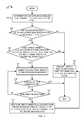
- FIG. 3is a flow diagram (“flow”) 300 illustrating example operations at a source WLAN device for determining whether data frames can be directly transmitted to a destination WLAN device.
- the flow 300begins at block 302 .
- a data frameis scheduled to be transmitted to a destination WLAN device.
- the data communication unit 106 of the source WLAN device 104can determine that the data frame is scheduled to be transmitted to the destination WLAN device 110 .
- the data communication unit 106may access a transmit data buffer and determine that the data frame is scheduled to be transmitted to the destination WLAN device 110 .
- the data communication unit 106may also determine a device identifier (e.g., a MAC address) of the destination WLAN device 110 .
- the flowcontinues at block 304 .
- the data communication unit 106may determine whether the destination WLAN device 110 and the source WLAN device 104 are part of the same BSS 100 . In other words, based on knowledge that the source WLAN device 104 is connected to the access point 102 , the data communication unit 106 may determine whether the destination WLAN device 110 is also connected to the access point 102 . The data communication unit 106 may query the network information unit 108 to determine whether the destination WLAN device 110 is also connected to the access point 102 . The network information unit 108 may access the connection information table 109 to determine whether the connection information table 109 comprises connection information about the destination WLAN device 110 .
- BSSbasic service set
- the access point 102transmits connection information associated with all WLAN devices in the BSS 100 . Therefore, absence of the connection information associated with the destination WLAN device 100 in the connection information table 109 can serve as an indication that the destination WLAN device 110 is not connected to the access point 102 . If it is determined that the destination WLAN device and the source WLAN device are part of a common BSS, the flow continues at block 306 . Otherwise, the flow continues at block 316 .
- a direct connect flag associated with the destination WLAN deviceindicates that the data frame can be directly transmitted to the destination WLAN device. For example, based on knowledge of the device identifier of the destination WLAN device 110 , the network information unit 108 can determine whether the direct connect flag associated with the destination WLAN device 110 indicates that the data frame can be directly transmitted to the destination WLAN device 110 . In one implementation, the network information unit 108 can determine whether the direct connect flag associated with the destination WLAN device 110 is set to “1” by accessing the connection information table 109 . If the direct connect flag is set to “1”, this indicates that the data frame can be directly transmitted to the destination WLAN device 110 .
- the direct connect flagis set to “0”, this indicates that the data frame should be transmitted to the destination WLAN device 110 via the access point 102 .
- the network information unit 108can transmit a notification to the data communication unit 106 indicating whether the data frame can be directly transmitted to the destination WLAN device 110 . If it is determined that the direct connect flag associated with the destination WLAN device indicates that the data frame can be directly transmitted to the destination WLAN device, the flow continues at block 308 . Otherwise, the flow continues at block 316 .
- the data frameis transmitted directly to the destination WLAN device.
- the data communication unit 106transmits the data frame to the destination WLAN device 110 .
- the data communication unit 106can transmit the address of the destination WLAN device in the first address field 256 , the address of the source WLAN device 104 in the second address field 258 , and an access point identifier in the third address field 260 to indicate that the source WLAN device 104 directly transmitted the data frame to the destination WLAN device 110 .
- the data communication unit 106can also set the “To” DS field 282 and the “From” DS field 284 in the frame control field 252 to “0” to indicate that the source WLAN device 104 directly transmitted the data frame to the destination WLAN device 110 .
- the flowcontinues at block 310 .
- the data communication unit 106determines whether the acknowledgement for the data frame was received from the destination WLAN device 110 .
- the data communication unit 106may wait for a predefined time interval to receive the acknowledgement frame from the destination WLAN device 110 . If it is determined that the acknowledgment frame was not received from the destination WLAN device 110 , the flow continues at block 312 . Otherwise, if it is determined that the acknowledgement was received from the destination WLAN device 110 , the transmission was successful and the flow ends.
- the data communication unit 106can determine whether the data frame should be retransmitted to the destination WLAN device 110 . In determining whether the data frame should be retransmitted, the data communication unit 106 may determine if a predefined retransmission time interval has expired. Also, the data communication unit 106 may determine if a maximum number of allowable retransmission attempts has been reached. If either the predefined retransmission time interval has expired or the maximum number of retransmission attempts has been reached, the data communication unit 106 can determine not to retransmit the data frame to the destination WLAN device 110 . If it is determined that the data frame should be retransmitted, the flow continues at block 308 where the data frame is retransmitted to the destination WLAN device. If it is determined that the data frame should not be retransmitted, the flow continues at block 314 .
- the direct connect flag associated with the destination WLAN deviceis updated to indicate that data frames cannot be directly transmitted to the destination WLAN device.
- the network information unit 108can update the direct connect flag associated with the destination WLAN device 110 to indicate that the data frames cannot be directly transmitted to the destination WLAN device 110 .
- the network information unit 108can update the direct connect flag associated with the destination WLAN device 110 in response to receiving a notification from the data communication unit 106 that the direct transmission to the destination WLAN device 110 failed.
- the network information unit 108can set the direct connect flag associated with the destination WLAN device 110 to “0” to indicate that data frames cannot be directly transmitted to the destination WLAN device 110 .
- the network information unit 108can set the direct connect flag associated with the destination WLAN device 110 to other suitable predefined value to indicate that data frames cannot be directly transmitted to the destination WLAN device 110 .
- the data communication unit 106 of the WLAN device 104can transmit the pending data frame and subsequent data frames intended for the destination WLAN device 110 via the access point 102 . From block 314 , the flow continues at block 316 .
- the data frameis transmitted to the access point for transmission to the destination WLAN device.
- the data communication unit 106transmits the data frame to the access point 102 .
- the flow 300moves from block 304 to block 316 if the data communication unit 106 determines that the destination WLAN device 110 and the source WLAN device 104 are not part of the same BSS 100 .
- the flow 300also moves from block 306 to block 316 if the data communication unit 106 determines that the direct connect flag associated with the destination WLAN device 110 indicates that the data frame cannot be directly transmitted to the destination WLAN device 110 .
- the flow 300moves from block 314 to block 316 if the data communication unit 106 determines that attempts to directly transmit the data frame to the destination WLAN device 110 have failed.
- the access point 102can accordingly route the data frame (e.g., via other access points, via ad-hoc WLAN networks, via an Ethernet network, etc.) to the destination WLAN device 110 . Alternately, the access point 102 may wait until the destination WLAN device 110 connects to the access point 102 . From block 316 , the flow ends.
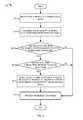
- FIG. 4is a flow diagram 400 illustrating example operations at a destination WLAN device for updating information indicating whether data frames can be directly transmitted to a source WLAN device.
- the flow 400begins at block 402 .
- a data frameis received at a destination WLAN device.
- the data communication unit 112 in the destination WLAN device 110may receive the data frame.
- the data communication unit 112may receive the data frame directly from the source WLAN device 104 .
- the data communication unit 112may receive the data frame from the access point 102 .
- the flowcontinues at block 404 .
- the address of the source WLAN deviceis determined from the received data frame.
- the data communication unit 112can determine the address of the source WLAN device 104 from the received data frame.
- the data communication unit 112can read the second address field 258 in the received data frame 250 of FIG. 2B and determine the address of the source WLAN device 104 .
- the flowcontinues at block 406 .
- the network information unit 114 of the destination WLAN device 110can determine whether the destination WLAN device 110 and the source WLAN device 104 are part of the same BSS 100 . In other words, the network information unit 114 can determine whether both the destination WLAN device 110 and the source WLAN device 104 are connected to the access point 102 .
- the network information unit 114can access the connection information table 115 comprising a list of device identifiers of WLAN devices connected to the access point 102 .
- the network information unit 114can determine whether the address of the source WLAN device 104 is listed in the connection information table 115 . If it is determined that the destination WLAN device and the source WLAN device are part of the same BSS, the flow contains at block 408 . Otherwise, the flow continues at block 410 , where the received data frame is processed.
- network information unit 114can determine whether the data frame was directly received from the source WLAN device 104 .
- the network information unit 114can read a “To” DS field 282 and a “From” DS field 284 in the frame control field 252 of the data frame 250 and can determine whether the data frame was directly received from the source WLAN device 104 .
- the network information unit 114can determine that the data frame was directly received from the source WLAN device 104 if the values in the “To” DS field 282 and a “From” DS field 284 are “0”.
- the network information unit 114may also read the second address field 258 in the received data frame 250 and determine that the source WLAN device 104 directly transmitted the data frame to the destination WLAN device 110 . If it is determined that the data frame was directly received from the source WLAN device, the flow continues at block 410 . Otherwise, the flow continues at block 412 .
- a direct connect flag associated with the source WLAN deviceis updated to indicate that data frames can be directly transmitted to the source WLAN device.
- the network information unit 114can update the direct connect flag associated with the source WLAN device 104 to indicate that the data frames can be directly transmitted to the source WLAN device 104 .
- the network information unit 114can set the direct connect flag associated with the source WLAN device 104 to “1” to indicate that the data frames can be directly transmitted to the source WLAN device 104 .
- the network information unit 114can set the direct connect flag associated with the source WLAN device 104 to other suitable predefined values to indicate that data frames can be directly transmitted to the source WLAN device 104 .
- the flowcontains at block 412 .
- the received data frameis processed.
- the data communication unit 112 and/or various other processing components in the destination WLAN device 110can process the received data frame. From block 412 , the flow ends.
- FIGS. 1-4are examples meant to aid in understanding embodiments and should not be used to limit embodiments or limit scope of the claims.
- Embodimentsmay perform additional operations, fewer operations, operations in a different order, operations in parallel, and some operations differently.
- the operations for determining whether the source WLAN device 104 and the destination WLAN device 110 are part of the same BSSmay be performed in conjunction with the operations for determining whether the data frame can be directly transmitted to the destination WLAN device (block 306 ).
- the direct connect flagcan serve as an indication of whether the source and the destination WLAN devices are part of the same BSS 100 and also whether the data frame can be directly transmitted to the destination WLAN device 110 .
- the source WLAN device 104can read the direct connect flag associated with the destination WLAN device 110 and determine that the direct connect flag is set to “1”. Accordingly, the source WLAN device 104 can confirm that the destination and the source WLAN devices are part of the same BSS and that the data frame can be directly transmitted to the destination WLAN device 110 .
- the destination WLAN device 110may remove the source WLAN device 104 from the connection information table 115 , may set the direct connect flag associated with the source WLAN device 104 to “0”, etc. In another embodiment, however, the destination WLAN device 110 may not have the ability to detect whether a WLAN device has left or joined the BSS 100 .
- the access point 102can update the connection information to reflect a new WLAN device in the BSS 100 and/or indicate that a WLAN device has left the BSS 100 .
- the access point 102can transmit the updated connection information in a next beacon interval to all the WLAN devices in the BSS 100 .
- the WLAN devicesin turn, can update their respective connection information tables to add new WLAN devices, remove WLAN devices that have left the BSS, etc.
- FIGS. 1-4depict a 1-bit direct connect flag having two valid values—one that indicates ability to directly receive data frames and the other that indicates inability to directly receive data frames, embodiments are not so limited.
- the direct connect flagcan comprise two or more bits and can be associated with more than two valid values.
- a first value of the direct connect flage.g., value 01
- a second value of the direct connect flage.g., value 00
- a third value of the direct connect flage.g., value 11
- the access point 102may transmit the third value of the direct connect flag as part the connection information associated with the WLAN device. If a source WLAN device 104 detects the third value of the direct connect flag associated with a destination WLAN device 110 , the source WLAN device 104 can attempt to directly communicate with the destination WLAN device 110 . If direct communication is successful, the source WLAN device 104 can update the connection information table to indicate that data frames can be directly transmitted to the destination WLAN device 110 . If direct communication fails, the source WLAN device 104 can update the connection information table to indicate that data frames cannot be directly transmitted to the destination WLAN device 110 . In some implementations, the source WLAN device 104 may also notify the access point 102 of whether or not data frames can be directly transmitted to the destination WLAN device 110 . The access point 102 can update its connection information and transmit the updated connection information at a next beacon interval.
- Embodimentsmay take the form of an entirely hardware embodiment, an entirely software embodiment (including firmware, resident software, micro-code, etc.) or an embodiment combining software and hardware aspects that may all generally be referred to herein as a “circuit,” “module” or “system.”
- embodiments of the inventive subject mattermay take the form of a computer program product embodied in any tangible medium of expression having computer usable program code embodied in the medium.
- the described embodimentsmay be provided as a computer program product, or software, that may include a machine-readable medium having stored thereon instructions, which may be used to program a computer system (or other electronic device(s)) to perform a process according to embodiments, whether presently described or not, since every conceivable variation is not enumerated herein.
- a machine-readable mediumincludes any mechanism for storing or transmitting information in a form (e.g., software, processing application) readable by a machine (e.g., a computer).
- a machine-readable mediummay be a non-transitory machine-readable storage medium, or a transitory machine-readable signal medium.
- a machine-readable storage mediummay include, for example, but is not limited to, magnetic storage medium (e.g., floppy diskette); optical storage medium (e.g., CD-ROM); magneto-optical storage medium; read only memory (ROM); random access memory (RAM); erasable programmable memory (e.g., EPROM and EEPROM); flash memory; or other types of tangible medium suitable for storing electronic instructions.
- a machine-readable signal mediummay include a propagated data signal with computer readable program code embodied therein, for example, an electrical, optical, acoustical or other form of propagated signal (e.g., carrier waves, infrared signals, digital signals, etc.).
- Program code embodied on a machine-readable mediummay be transmitted using any suitable medium, including, but not limited to, wireline, wireless, optical fiber cable, RF, or other communications medium.
- Computer program code for carrying out operations of the embodimentsmay be written in any combination of one or more programming languages, including an object oriented programming language such as Java, Smalltalk, C++ or the like and conventional procedural programming languages, such as the “C” programming language or similar programming languages.
- the program codemay execute entirely on a user's computer, partly on the user's computer, as a stand-alone software package, partly on the user's computer and partly on a remote computer or entirely on the remote computer or server.
- the remote computermay be connected to the user's computer through any type of network, including a local area network (LAN), a personal area network (PAN), or a wide area network (WAN), or the connection may be made to an external computer (for example, through the Internet using an Internet Service Provider).
- LANlocal area network
- PANpersonal area network
- WANwide area network
- Internet Service Providerfor example, AT&T, MCI, Sprint, EarthLink, MSN, GTE, etc.
- FIG. 5is a block diagram of one embodiment of an electronic device 500 including a mechanism for direct data communication in an infrastructure WLAN.
- the electronic device 500may be one of a personal computer (PC), a laptop, a netbook, a mobile phone, a personal digital assistant (PDA), or other electronic systems comprising a WLAN device.
- the electronic device 500includes a processor device 502 (possibly including multiple processors, multiple cores, multiple nodes, and/or implementing multi-threading, etc.).
- the electronic device 500includes a memory unit 506 .
- the memory unit 506may be system memory (e.g., one or more of cache, SRAM, DRAM, zero capacitor RAM, Twin Transistor RAM, eDRAM, EDO RAM, DDR RAM, EEPROM, NRAM, RRAM, SONOS, PRAM, etc.) or any one or more of the above already described possible realizations of machine-readable media.
- the electronic device 500also includes a bus 510 (e.g., PCI, ISA, PCI-Express, HyperTransport®, InfiniBand®, NuBus, etc.), and network interfaces 504 that include at least one wireless network interface (e.g., a WLAN interface, a Bluetooth® interface, a WiMAX interface, a ZigBee® interface, a Wireless USB interface, etc.).
- the electronic device 500also includes a WLAN device 508 .
- the WLAN device 508comprises a data communication unit 520 coupled to a network information unit 522 .
- the network information unit 522implements functionality for determining whether data frames can be directly transmitted to a destination WLAN device based on determining a status of a direct connect flag associated with the destination WLAN device, as described above with reference to FIGS. 1-4 .
- the data communication unit 520can transmit the data frames directly to the destination WLAN device or via an access point based on indications from the network information unit 522 , as described above with reference to FIGS. 1-4 . It should be noted that any one of the above-described functionalities might be partially (or entirely) implemented in hardware and/or on the processor device 502 .
- the functionalitymay be implemented with an application specific integrated circuit, in logic implemented in the processor device 502 , in a co-processor on a peripheral device or card, etc. Further, realizations may include fewer or additional components not illustrated in FIG. 5 (e.g., additional network interfaces, peripheral devices, etc.).
- the processor device 502 and the network interfaces 504are coupled to the bus 510 . Although illustrated as being coupled to the bus 510 , the memory unit 506 may be coupled to the processor device 502 .
Landscapes
- Engineering & Computer Science (AREA)
- Computer Networks & Wireless Communication (AREA)
- Signal Processing (AREA)
- Mobile Radio Communication Systems (AREA)
Abstract
Description
Claims (21)
Priority Applications (2)
| Application Number | Priority Date | Filing Date | Title |
|---|---|---|---|
| US12/768,434US8588156B1 (en) | 2010-04-27 | 2010-04-27 | Direct data communication in infrastructure mode in wireless communication systems |
| US14/049,661US9137838B2 (en) | 2010-04-27 | 2013-10-09 | Direct data communication in infrastructure mode in wireless communication systems |
Applications Claiming Priority (1)
| Application Number | Priority Date | Filing Date | Title |
|---|---|---|---|
| US12/768,434US8588156B1 (en) | 2010-04-27 | 2010-04-27 | Direct data communication in infrastructure mode in wireless communication systems |
Related Child Applications (1)
| Application Number | Title | Priority Date | Filing Date |
|---|---|---|---|
| US14/049,661ContinuationUS9137838B2 (en) | 2010-04-27 | 2013-10-09 | Direct data communication in infrastructure mode in wireless communication systems |
Publications (1)
| Publication Number | Publication Date |
|---|---|
| US8588156B1true US8588156B1 (en) | 2013-11-19 |
Family
ID=49555798
Family Applications (2)
| Application Number | Title | Priority Date | Filing Date |
|---|---|---|---|
| US12/768,434Expired - Fee RelatedUS8588156B1 (en) | 2010-04-27 | 2010-04-27 | Direct data communication in infrastructure mode in wireless communication systems |
| US14/049,661Expired - Fee RelatedUS9137838B2 (en) | 2010-04-27 | 2013-10-09 | Direct data communication in infrastructure mode in wireless communication systems |
Family Applications After (1)
| Application Number | Title | Priority Date | Filing Date |
|---|---|---|---|
| US14/049,661Expired - Fee RelatedUS9137838B2 (en) | 2010-04-27 | 2013-10-09 | Direct data communication in infrastructure mode in wireless communication systems |
Country Status (1)
| Country | Link |
|---|---|
| US (2) | US8588156B1 (en) |
Cited By (8)
| Publication number | Priority date | Publication date | Assignee | Title |
|---|---|---|---|---|
| US20130235820A1 (en)* | 2012-03-12 | 2013-09-12 | Htc Corporation | Method and Apparatus for Performing Direct Communications in Wireless Communication System |
| US20140036898A1 (en)* | 2010-04-27 | 2014-02-06 | Qualcomm Incorporated | Direct data communication in infrastructure mode in wireless communication systems |
| US9049658B2 (en) | 2012-03-06 | 2015-06-02 | Qualcomm Incorporated | Power save mechanism for peer-to-peer communication networks |
| US9185655B2 (en) | 2010-02-12 | 2015-11-10 | Qualcomm Incorporated | Dynamic power mode switch in a wireless ad-hoc system |
| US9288753B2 (en) | 2009-05-05 | 2016-03-15 | Qualcomm Incorporated | Dynamic energy saving mechanism for access points |
| US9311446B1 (en) | 2010-03-19 | 2016-04-12 | Qualcomm Incorporated | Multicast transmission for power management in an ad-hoc wireless system |
| US20160261568A1 (en)* | 2015-03-04 | 2016-09-08 | Neone, Inc. | Secure Distributed Device-to-Device Network |
| US20250088854A1 (en)* | 2023-09-12 | 2025-03-13 | Qualcomm Incorporated | Frame protection in wireless communications |
Families Citing this family (6)
| Publication number | Priority date | Publication date | Assignee | Title |
|---|---|---|---|---|
| JP5921506B2 (en)* | 2013-09-10 | 2016-05-24 | 株式会社東芝 | Communication apparatus and communication method |
| JP2015056696A (en)* | 2013-09-10 | 2015-03-23 | 株式会社東芝 | Communication apparatus and communication method |
| US10069649B2 (en)* | 2013-11-06 | 2018-09-04 | Citrix Systems, Inc. | Systems and methods for performing service tag switching in an application delivery controller |
| TWI508609B (en)* | 2014-01-08 | 2015-11-11 | 晶睿通訊股份有限公司 | Network configuration method and wireless networking system |
| US10880304B2 (en)* | 2016-04-06 | 2020-12-29 | Qualcomm Incorporated | Network verification of wearable devices |
| US10212730B1 (en)* | 2016-04-14 | 2019-02-19 | Marvell International Ltd. | Partial association identifier (AID) length change notification |
Citations (56)
| Publication number | Priority date | Publication date | Assignee | Title |
|---|---|---|---|---|
| US20020045435A1 (en) | 2000-10-18 | 2002-04-18 | Steve Fantaske | Wireless communication system |
| US6421714B1 (en) | 1997-10-14 | 2002-07-16 | Lucent Technologies | Efficient mobility management scheme for a wireless internet access system |
| US20020164963A1 (en) | 2001-04-09 | 2002-11-07 | Tehrani Ardavan Maleki | Method and system for providing antenna diversity |
| US6570857B1 (en) | 1998-01-13 | 2003-05-27 | Telefonaktiebolaget L M Ericsson | Central multiple access control for frequency hopping radio networks |
| US6580704B1 (en)* | 1999-08-26 | 2003-06-17 | Nokia Corporation | Direct mode communication method between two mobile terminals in access point controlled wireless LAN systems |
| US6829493B1 (en) | 2000-04-24 | 2004-12-07 | Denso Corporation | Adaptive adjustment of sleep duration to increase standby time in wireless mobile stations |
| US6836472B2 (en) | 1996-05-13 | 2004-12-28 | Micron Technology, Inc. | Radio frequency data communications device |
| US20050136914A1 (en) | 2003-12-22 | 2005-06-23 | Harald Van Kampen | Power management method for creating deliver opportunities in a wireless communication system |
| US20050135284A1 (en) | 2003-10-15 | 2005-06-23 | Qualcomm Incorporated | High speed media access control |
| US20050152324A1 (en) | 2004-01-12 | 2005-07-14 | Mathilde Benveniste | Efficient power management in wireless local area networks |
| US20050286454A1 (en) | 2004-06-28 | 2005-12-29 | Nec Corporation | Power saving method in wireless LAN system for permitting terminal station to promptly transition to doze state by transmitting empty data frame |
| US20060029024A1 (en) | 2004-08-05 | 2006-02-09 | Guang Zeng | System and method for battery conservation in wireless stations |
| US20070077936A1 (en) | 2004-06-29 | 2007-04-05 | Mitsubishi Denki Kabushiki Kaisha | Wireless base station and wireless communication system |
| US20070171910A1 (en) | 2005-10-05 | 2007-07-26 | Ravi Kumar | Peer-to-peer communication in ad hoc wireless network |
| US7260068B2 (en) | 2003-01-23 | 2007-08-21 | Mediatek Inc. | Method for switching a time frame based mobile unit to a sleep mode |
| USRE40032E1 (en) | 1993-03-06 | 2008-01-22 | Agere Systems Inc. | Wireless data communication system having power saving function |
| US20080069021A1 (en) | 2006-09-14 | 2008-03-20 | Kapil Chhabra | Ad-hoc network power save system and method |
| US7457271B2 (en) | 2003-09-19 | 2008-11-25 | Marvell International Ltd. | Wireless local area network ad-hoc mode for reducing power consumption |
| US20090016248A1 (en) | 2007-07-10 | 2009-01-15 | Qualcomm Incorporated | Coding methods of communicating identifiers in peer discovery in a peer-to-peer network |
| US7505795B1 (en) | 2004-07-07 | 2009-03-17 | Advanced Micro Devices, Inc. | Power save management with customized range for user configuration and tuning value based upon recent usage |
| US20090073945A1 (en) | 2007-09-18 | 2009-03-19 | Lg Electronics Inc. | Direct link setup procedure in tunneled direct link setup wireless network and station supporting the procedure |
| US20090097438A1 (en) | 2007-10-10 | 2009-04-16 | Jarkko Kneckt | System and method for transmissions in power save mode |
| US7567815B2 (en) | 2004-03-04 | 2009-07-28 | Sony Corporation | Wireless communication apparatus for synchronizing a frame cycle's beginning position in relation to other devices |
| US20090196211A1 (en) | 2008-02-01 | 2009-08-06 | Maarten Menzo Wentink | Unscheduled peer power save mode |
| US20090310578A1 (en)* | 2006-07-19 | 2009-12-17 | Stmicroelectronics S.R.L. | Method and system for enabling multi-channel direct link connection in a communication network, related network and computer program product |
| EP2157739A1 (en) | 2007-06-04 | 2010-02-24 | Sony Corporation | Communication system, communication device, communication method, and computer program |
| US20100070767A1 (en) | 2005-11-03 | 2010-03-18 | Intel Corporation | Method and system of secured direct link set-up (DLS) for wireless networks |
| US20100118797A1 (en) | 2008-11-13 | 2010-05-13 | Qualcomm Incorporated | Methods and systems using fast dl / ul synchronization for mobile systems |
| US20100128701A1 (en) | 2008-11-24 | 2010-05-27 | Qualcomm Incorporated | Beacon transmission for participation in peer-to-peer formation and discovery |
| US20100153727A1 (en) | 2008-12-17 | 2010-06-17 | Interdigital Patent Holdings, Inc. | Enhanced security for direct link communications |
| US20100189021A1 (en) | 2007-02-27 | 2010-07-29 | Thomson Broadband R & D (Beijing) Col. Ltd. | Method and apparatus for power management in wlan |
| US7804849B2 (en) | 1993-08-03 | 2010-09-28 | Broadcom Corporation | System and method for controlling communication in a multi-network environment |
| US20100254290A1 (en) | 2009-04-07 | 2010-10-07 | Gong Michelle X | Device power management in a wireless network |
| US20100284316A1 (en) | 2009-05-05 | 2010-11-11 | Atheros Communications, Inc. | Dynamic energy saving mechanism for access points |
| US20100325459A1 (en) | 2009-06-19 | 2010-12-23 | Texas Instruments Incorporated | Peer-to-peer group owner enhanced power management |
| US7864720B2 (en) | 2007-06-01 | 2011-01-04 | Intel Corporation | Power management for wireless devices |
| US20110051638A1 (en) | 2006-10-13 | 2011-03-03 | Beom Jin Jeon | Method for managing the power in the wireless network |
| US7916663B2 (en) | 2006-09-18 | 2011-03-29 | Marvell International Ltd. | Establishment of ad-hoc networks between multiple devices |
| US20110086662A1 (en) | 2008-03-10 | 2011-04-14 | Nortel Works Limited | Methods for control signaling for wireless systems |
| US20110158142A1 (en) | 2009-12-24 | 2011-06-30 | Michelle Gong | Method and system for power management in an ad hoc network |
| US7978638B2 (en) | 2004-08-09 | 2011-07-12 | Lg Electronics Inc. | Method of transmitting network information in broadband wireless access system |
| US7995507B2 (en) | 2006-12-04 | 2011-08-09 | Samsung Electronics Co., Ltd. | System and method for wireless communication of uncompressed video having power saving capability |
| US8014370B2 (en)* | 2006-04-24 | 2011-09-06 | Marvell World Trade Ltd. | 802.11 mesh architecture |
| US8023522B2 (en) | 2009-03-30 | 2011-09-20 | Intel Corporation | Enabling long-term communication idleness for energy efficiency |
| US20110237294A1 (en) | 2008-03-18 | 2011-09-29 | Hussain Farooq S | Power management for multimode wireless communication device |
| US8045494B2 (en) | 2004-02-06 | 2011-10-25 | Koninklijke Philips Electronics N.V. | System and method for hibernation mode for beaconing devices |
| US20110280170A1 (en) | 2008-07-03 | 2011-11-17 | Robert Bowser | Multiple density configurations and algorithms for intelligent power savings infrastructure in wireless lans |
| US8072913B2 (en) | 2008-02-03 | 2011-12-06 | Broadcom Corporation | Collaborative coexistence of co-located mobile WiMAX, wireless LAN, and/or bluetooth radios |
| US8099047B2 (en) | 2004-03-17 | 2012-01-17 | Alcatel Lucent | Method for controlling the sleep mode on a mobile terminal, corresponding mobile terminal, and corresponding radio access node |
| US8098635B2 (en) | 2005-08-26 | 2012-01-17 | Qualcomm Incorporated | Method and apparatus for packet communications in wireless systems |
| US20120021735A1 (en) | 2008-10-27 | 2012-01-26 | Nec Corporation | Method for operating a wimax femtocell base station and femtocell base station |
| US8112650B2 (en) | 2008-09-17 | 2012-02-07 | Qualcomm Incorporated | Adaptive method for system re-acquisition in power saving mode operation in a mobile wiMAX system |
| US20120151089A1 (en) | 2010-12-08 | 2012-06-14 | Atheros Communications, Inc. | Direct data communication in a peer-to-peer network |
| US8233462B2 (en) | 2003-10-15 | 2012-07-31 | Qualcomm Incorporated | High speed media access control and direct link protocol |
| US20130028206A1 (en) | 2009-02-10 | 2013-01-31 | Lg Electronics Inc. | Method and apparatus for updating system information in broadband wireless communication system |
| US20130204936A1 (en) | 2009-11-25 | 2013-08-08 | Telefonaktiebolaget L M Ericsson (Publ) | Peer-To-Peer Communication of Non-Common Data |
Family Cites Families (30)
| Publication number | Priority date | Publication date | Assignee | Title |
|---|---|---|---|---|
| GB9304638D0 (en) | 1993-03-06 | 1993-04-21 | Ncr Int Inc | Wireless data communication system having power saving function |
| US5754870A (en) | 1996-02-16 | 1998-05-19 | New Media Corp. | Power management of a computer plug-in card having a remote data link |
| US7634275B2 (en) | 2002-07-03 | 2009-12-15 | Freescale Semiconductor, Inc. | Method of accommodating periodic interfering signals in a wireless network |
| US8064474B2 (en) | 2003-03-20 | 2011-11-22 | Qualcomm Atheros, Inc. | Method and apparatus for selecting a responder to enable reliable multicast |
| US7660578B2 (en) | 2003-05-02 | 2010-02-09 | Nokia Corporation | Method for saving power in a wireless terminal and a terminal |
| US7457973B2 (en) | 2003-06-20 | 2008-11-25 | Texas Instruments Incorporated | System and method for prioritizing data transmission and transmitting scheduled wake-up times to network stations based on downlink transmission duration |
| KR101080970B1 (en) | 2004-12-27 | 2011-11-09 | 엘지전자 주식회사 | Method for Transmitting Decode Information in Broadband Wireless Access System |
| US7881755B1 (en) | 2005-05-26 | 2011-02-01 | Marvell International Ltd. | Wireless LAN power savings |
| US20060292987A1 (en) | 2005-06-27 | 2006-12-28 | Lior Ophir | Method of wireless local area network and Bluetooth network coexistence in a collocated device |
| US7583984B2 (en) | 2005-08-12 | 2009-09-01 | Lg Electronics Inc. | Method of providing notification for battery power conservation in a wireless system |
| US20070076683A1 (en) | 2005-09-30 | 2007-04-05 | Chung Ching A | Low power module for a station of a wireless communication system and related method |
| US8249636B2 (en) | 2005-10-12 | 2012-08-21 | Qualcomm Incorporated | Method and apparatus for detecting adverse channel conditions and conserving power |
| US8233456B1 (en) | 2006-10-16 | 2012-07-31 | Marvell International Ltd. | Power save mechanisms for dynamic ad-hoc networks |
| US7848278B2 (en) | 2006-10-23 | 2010-12-07 | Telcordia Technologies, Inc. | Roadside network unit and method of organizing, managing and maintaining local network using local peer groups as network groups |
| CN101637051B (en) | 2007-01-11 | 2012-10-31 | 高通股份有限公司 | Using DTX and DRX in Wireless Communication Systems |
| TW201538014A (en) | 2007-02-05 | 2015-10-01 | Interdigital Tech Corp | Paging over a high-speed downlink shared channel |
| US20090034443A1 (en) | 2007-07-30 | 2009-02-05 | Jesse Walker | Power saving idle mode algorithm for an access point |
| US20090279467A1 (en) | 2008-05-09 | 2009-11-12 | Samsung Electronics Co., Ltd. | Adaptive and effective power saving design |
| US8498607B2 (en) | 2008-06-12 | 2013-07-30 | Qualcomm Incorporated | Methods and systems for power savings using a message indication header |
| EP2321983B1 (en) | 2008-09-04 | 2018-05-09 | Trilliant Networks, Inc. | Method for implementing mesh network communications using a mesh network protocol |
| US8185138B2 (en) | 2008-10-13 | 2012-05-22 | Qualcomm Incorporated | Paging messages for power saving in a mobile WiMAX system |
| US8576761B1 (en) | 2009-09-18 | 2013-11-05 | Qualcomm Incorporated | Power save delivery mechanism for wireless communication traffic |
| JP5440123B2 (en) | 2009-11-24 | 2014-03-12 | ソニー株式会社 | Wireless communication apparatus, wireless communication system, wireless communication method, and program |
| US8335937B2 (en) | 2009-12-24 | 2012-12-18 | Intel Corporation | Method and system for discoverability of power saving P2P devices |
| US8537733B1 (en) | 2010-02-12 | 2013-09-17 | Qualcomm Incorporated | Dynamic power mode switch in a wireless ad-hoc system |
| US8588156B1 (en)* | 2010-04-27 | 2013-11-19 | Qualcomm Incorporated | Direct data communication in infrastructure mode in wireless communication systems |
| US8526346B1 (en)* | 2010-04-28 | 2013-09-03 | Qualcomm Incorporated | Power save communication mechanism for wireless communication systems |
| US8611268B1 (en) | 2011-04-15 | 2013-12-17 | Qualcomm Incorporated | Access point power save mechanism for wireless communication systems |
| US9491738B2 (en) | 2012-02-03 | 2016-11-08 | Qualcomm Incorporated | Managing downlink and uplink resources for low cost user equipments |
| US9049658B2 (en) | 2012-03-06 | 2015-06-02 | Qualcomm Incorporated | Power save mechanism for peer-to-peer communication networks |
- 2010
- 2010-04-27USUS12/768,434patent/US8588156B1/ennot_activeExpired - Fee Related
- 2013
- 2013-10-09USUS14/049,661patent/US9137838B2/ennot_activeExpired - Fee Related
Patent Citations (58)
| Publication number | Priority date | Publication date | Assignee | Title |
|---|---|---|---|---|
| USRE40032E1 (en) | 1993-03-06 | 2008-01-22 | Agere Systems Inc. | Wireless data communication system having power saving function |
| US7804849B2 (en) | 1993-08-03 | 2010-09-28 | Broadcom Corporation | System and method for controlling communication in a multi-network environment |
| US6836472B2 (en) | 1996-05-13 | 2004-12-28 | Micron Technology, Inc. | Radio frequency data communications device |
| US6421714B1 (en) | 1997-10-14 | 2002-07-16 | Lucent Technologies | Efficient mobility management scheme for a wireless internet access system |
| US6570857B1 (en) | 1998-01-13 | 2003-05-27 | Telefonaktiebolaget L M Ericsson | Central multiple access control for frequency hopping radio networks |
| US6580704B1 (en)* | 1999-08-26 | 2003-06-17 | Nokia Corporation | Direct mode communication method between two mobile terminals in access point controlled wireless LAN systems |
| US6829493B1 (en) | 2000-04-24 | 2004-12-07 | Denso Corporation | Adaptive adjustment of sleep duration to increase standby time in wireless mobile stations |
| US20020045435A1 (en) | 2000-10-18 | 2002-04-18 | Steve Fantaske | Wireless communication system |
| US20020164963A1 (en) | 2001-04-09 | 2002-11-07 | Tehrani Ardavan Maleki | Method and system for providing antenna diversity |
| US7577114B2 (en) | 2003-01-23 | 2009-08-18 | Mediatek Inc. | Method for controlling a mobile communication device to enter a power-saving mode and to recover timing after the mobile communication device leaves the power-saving mode |
| US7260068B2 (en) | 2003-01-23 | 2007-08-21 | Mediatek Inc. | Method for switching a time frame based mobile unit to a sleep mode |
| US7457271B2 (en) | 2003-09-19 | 2008-11-25 | Marvell International Ltd. | Wireless local area network ad-hoc mode for reducing power consumption |
| US8233462B2 (en) | 2003-10-15 | 2012-07-31 | Qualcomm Incorporated | High speed media access control and direct link protocol |
| US20050135284A1 (en) | 2003-10-15 | 2005-06-23 | Qualcomm Incorporated | High speed media access control |
| US20050136914A1 (en) | 2003-12-22 | 2005-06-23 | Harald Van Kampen | Power management method for creating deliver opportunities in a wireless communication system |
| US20050152324A1 (en) | 2004-01-12 | 2005-07-14 | Mathilde Benveniste | Efficient power management in wireless local area networks |
| US8045494B2 (en) | 2004-02-06 | 2011-10-25 | Koninklijke Philips Electronics N.V. | System and method for hibernation mode for beaconing devices |
| US7567815B2 (en) | 2004-03-04 | 2009-07-28 | Sony Corporation | Wireless communication apparatus for synchronizing a frame cycle's beginning position in relation to other devices |
| US8099047B2 (en) | 2004-03-17 | 2012-01-17 | Alcatel Lucent | Method for controlling the sleep mode on a mobile terminal, corresponding mobile terminal, and corresponding radio access node |
| US20050286454A1 (en) | 2004-06-28 | 2005-12-29 | Nec Corporation | Power saving method in wireless LAN system for permitting terminal station to promptly transition to doze state by transmitting empty data frame |
| US20070077936A1 (en) | 2004-06-29 | 2007-04-05 | Mitsubishi Denki Kabushiki Kaisha | Wireless base station and wireless communication system |
| US7505795B1 (en) | 2004-07-07 | 2009-03-17 | Advanced Micro Devices, Inc. | Power save management with customized range for user configuration and tuning value based upon recent usage |
| US20060029024A1 (en) | 2004-08-05 | 2006-02-09 | Guang Zeng | System and method for battery conservation in wireless stations |
| US7978638B2 (en) | 2004-08-09 | 2011-07-12 | Lg Electronics Inc. | Method of transmitting network information in broadband wireless access system |
| US8098635B2 (en) | 2005-08-26 | 2012-01-17 | Qualcomm Incorporated | Method and apparatus for packet communications in wireless systems |
| US20070171910A1 (en) | 2005-10-05 | 2007-07-26 | Ravi Kumar | Peer-to-peer communication in ad hoc wireless network |
| US20100070767A1 (en) | 2005-11-03 | 2010-03-18 | Intel Corporation | Method and system of secured direct link set-up (DLS) for wireless networks |
| US8014370B2 (en)* | 2006-04-24 | 2011-09-06 | Marvell World Trade Ltd. | 802.11 mesh architecture |
| US20090310578A1 (en)* | 2006-07-19 | 2009-12-17 | Stmicroelectronics S.R.L. | Method and system for enabling multi-channel direct link connection in a communication network, related network and computer program product |
| US20080069021A1 (en) | 2006-09-14 | 2008-03-20 | Kapil Chhabra | Ad-hoc network power save system and method |
| US7916663B2 (en) | 2006-09-18 | 2011-03-29 | Marvell International Ltd. | Establishment of ad-hoc networks between multiple devices |
| US20110051638A1 (en) | 2006-10-13 | 2011-03-03 | Beom Jin Jeon | Method for managing the power in the wireless network |
| US7995507B2 (en) | 2006-12-04 | 2011-08-09 | Samsung Electronics Co., Ltd. | System and method for wireless communication of uncompressed video having power saving capability |
| US20100189021A1 (en) | 2007-02-27 | 2010-07-29 | Thomson Broadband R & D (Beijing) Col. Ltd. | Method and apparatus for power management in wlan |
| US7864720B2 (en) | 2007-06-01 | 2011-01-04 | Intel Corporation | Power management for wireless devices |
| EP2157739A1 (en) | 2007-06-04 | 2010-02-24 | Sony Corporation | Communication system, communication device, communication method, and computer program |
| US20090016248A1 (en) | 2007-07-10 | 2009-01-15 | Qualcomm Incorporated | Coding methods of communicating identifiers in peer discovery in a peer-to-peer network |
| US20090073945A1 (en) | 2007-09-18 | 2009-03-19 | Lg Electronics Inc. | Direct link setup procedure in tunneled direct link setup wireless network and station supporting the procedure |
| US20090097438A1 (en) | 2007-10-10 | 2009-04-16 | Jarkko Kneckt | System and method for transmissions in power save mode |
| US20090196211A1 (en) | 2008-02-01 | 2009-08-06 | Maarten Menzo Wentink | Unscheduled peer power save mode |
| US8072913B2 (en) | 2008-02-03 | 2011-12-06 | Broadcom Corporation | Collaborative coexistence of co-located mobile WiMAX, wireless LAN, and/or bluetooth radios |
| US20110086662A1 (en) | 2008-03-10 | 2011-04-14 | Nortel Works Limited | Methods for control signaling for wireless systems |
| US20110237294A1 (en) | 2008-03-18 | 2011-09-29 | Hussain Farooq S | Power management for multimode wireless communication device |
| US20110280170A1 (en) | 2008-07-03 | 2011-11-17 | Robert Bowser | Multiple density configurations and algorithms for intelligent power savings infrastructure in wireless lans |
| US8112650B2 (en) | 2008-09-17 | 2012-02-07 | Qualcomm Incorporated | Adaptive method for system re-acquisition in power saving mode operation in a mobile wiMAX system |
| US20120021735A1 (en) | 2008-10-27 | 2012-01-26 | Nec Corporation | Method for operating a wimax femtocell base station and femtocell base station |
| US20100118797A1 (en) | 2008-11-13 | 2010-05-13 | Qualcomm Incorporated | Methods and systems using fast dl / ul synchronization for mobile systems |
| US20100128701A1 (en) | 2008-11-24 | 2010-05-27 | Qualcomm Incorporated | Beacon transmission for participation in peer-to-peer formation and discovery |
| US20100153727A1 (en) | 2008-12-17 | 2010-06-17 | Interdigital Patent Holdings, Inc. | Enhanced security for direct link communications |
| US20130028206A1 (en) | 2009-02-10 | 2013-01-31 | Lg Electronics Inc. | Method and apparatus for updating system information in broadband wireless communication system |
| US8023522B2 (en) | 2009-03-30 | 2011-09-20 | Intel Corporation | Enabling long-term communication idleness for energy efficiency |
| US20100254290A1 (en) | 2009-04-07 | 2010-10-07 | Gong Michelle X | Device power management in a wireless network |
| US20100284316A1 (en) | 2009-05-05 | 2010-11-11 | Atheros Communications, Inc. | Dynamic energy saving mechanism for access points |
| US20100325459A1 (en) | 2009-06-19 | 2010-12-23 | Texas Instruments Incorporated | Peer-to-peer group owner enhanced power management |
| US20130204936A1 (en) | 2009-11-25 | 2013-08-08 | Telefonaktiebolaget L M Ericsson (Publ) | Peer-To-Peer Communication of Non-Common Data |
| US20110158142A1 (en) | 2009-12-24 | 2011-06-30 | Michelle Gong | Method and system for power management in an ad hoc network |
| US20120151089A1 (en) | 2010-12-08 | 2012-06-14 | Atheros Communications, Inc. | Direct data communication in a peer-to-peer network |
| WO2012078379A1 (en) | 2010-12-08 | 2012-06-14 | Qualcomm Atheros, Inc. | Direct data communication for p2p networks |
Non-Patent Citations (30)
| Title |
|---|
| "IEEE Std 802.11z: IEEE Standard for Information Technology-Amendment 7: Extensions to Direct-Link Setup", IEEE Computer Society 3 Park Avenue New York, NY 10016-5997 http://ieeexplore.ieee.org/xpl/freeabs-all.jsp?arnumber=5605400 Oct. 14, 2010 , 96 pages. |
| "PCT Application No. PCT/US11/62154 International Preliminary Report on Patentability", Jun. 20, 2013 , 8 pages. |
| "PCT Application No. PCT/US2011/062154 International Search Report", Mar. 6, 2012 , 13 pages. |
| "PCT Application No. PCT/US2013/029377 International Search Report", Jun. 17, 2013 , 11 pages. |
| "U.S. Appl. No. 12/562,819 Office Action", Feb. 5, 2013 , 29 pages. |
| "U.S. Appl. No. 12/562,819 Office Action",Nov. 14, 2011, 26 pages. |
| "U.S. Appl. No. 12/768,912 Final Office Action", Feb. 22, 2013 , 27 Pages. |
| "U.S. Appl. No. 12/963,160 Final Office Action", Aug. 15, 2013, 19 pages. |
| "U.S. Appl. No. 12/963,160 Office Action", Apr. 16, 2013, 25 pages. |
| "U.S. Appl. No. 13/088,081 Non-Final Office Action", Apr. 24, 2013 , 14 Pages. |
| Co-pending U.S. Appl. No. 113/966,870, filed Sep. 14, 2013, 47 pages. |
| Co-pending U.S. Appl. No. 12/562,819, filed Sep. 18, 2009. |
| Co-pending U.S. Appl. No. 12/705,267, filed Feb. 12, 2010. |
| Co-pending U.S. Appl. No. 12/727,610, filed Mar. 19, 2010. |
| Co-pending U.S. Appl. No. 12/768,912, filed Apr. 28, 2010. |
| Co-pending U.S. Appl. No. 13/088,081, filed Apr. 15, 2011. |
| Co-pending U.S. Appl. No. 13/413,011, filed Mar. 6, 2012. |
| Co-pending U.S. Appl. No. 13/955,779, filed Jul 31, 2013, 44 pages. |
| IEEE Standard for Information technology-Telecommunications and information exchange between systems-Local and metropolitan area networks-Specific requirements-Part 11: Wireless LAN Medium Access Control (MAC) and Physical Layer (PHY) Specifications, IEEE Std 802.11-2007 (Revision of IEEE Std 802.11-1999) http://standards.ieee.org/getieee802/download/802.11-2007.pdf. (Date Obtained from Internet Oct. 21, 2009) Jun. 12, 2007 , pp. 59-312. |
| IEEE, "Wireless LAN Medium Access Control (MAC) and Physical Layer (PHY) Specifications", IEEE Standard for Information Technology Section 11.0, http://standards.ieee.org/getieee802/downtoad/802.11-2007.pdf Jun. 12, 2007, pp. 419-468. |
| Jung Eun-Sun et al., "A Power Control MAC Protocol for Ad Hoc Networks", 2002 , 12 pages. |
| U.S. Appl. No. 12/492,405 Office Action, Mar. 15, 2012, 9 pages. |
| U.S. Appl. No. 12/492,405 Office Action, Sep. 27, 2012, 10 Pages. |
| U.S. Appl. No. 12/562,819 Final Office Action, May 3, 2012, 31 pages. |
| U.S. Appl. No. 12/705,267 Office Action, Mar. 22, 2012, 11 pages. |
| U.S. Appl. No. 12/727,610 Final Office Action, Jan. 7, 2013, 24 pages. |
| U.S. Appl. No. 12/727,610 Office Action, Aug. 2, 2012, 20 pages. |
| U.S. Appl. No. 12/768,434 Office Action, Oct. 15, 2012, 11 pages. |
| U.S. Appl. No. 12/768,912 Office Action, Sep. 7, 2012, 23 Pages. |
| U.S. Appl. No. 12/963,160, filed Dec. 8, 2010, Ponmudi, Kayalvizhi. |
Cited By (13)
| Publication number | Priority date | Publication date | Assignee | Title |
|---|---|---|---|---|
| US9288753B2 (en) | 2009-05-05 | 2016-03-15 | Qualcomm Incorporated | Dynamic energy saving mechanism for access points |
| US9185655B2 (en) | 2010-02-12 | 2015-11-10 | Qualcomm Incorporated | Dynamic power mode switch in a wireless ad-hoc system |
| US9311446B1 (en) | 2010-03-19 | 2016-04-12 | Qualcomm Incorporated | Multicast transmission for power management in an ad-hoc wireless system |
| US9137838B2 (en)* | 2010-04-27 | 2015-09-15 | Qualcomm Incorporated | Direct data communication in infrastructure mode in wireless communication systems |
| US20140036898A1 (en)* | 2010-04-27 | 2014-02-06 | Qualcomm Incorporated | Direct data communication in infrastructure mode in wireless communication systems |
| US9049658B2 (en) | 2012-03-06 | 2015-06-02 | Qualcomm Incorporated | Power save mechanism for peer-to-peer communication networks |
| US9832725B2 (en) | 2012-03-06 | 2017-11-28 | Qualcomm Incorporated | Power save mechanism for peer-to-peer communication networks |
| US20130235820A1 (en)* | 2012-03-12 | 2013-09-12 | Htc Corporation | Method and Apparatus for Performing Direct Communications in Wireless Communication System |
| US9226298B2 (en)* | 2012-03-12 | 2015-12-29 | Htc Corporation | Method and apparatus for performing direct communications in wireless communication system |
| US10091790B2 (en) | 2012-03-12 | 2018-10-02 | Htc Corporation | Method and apparatus for performing direct communications in wireless communication system |
| US20160261568A1 (en)* | 2015-03-04 | 2016-09-08 | Neone, Inc. | Secure Distributed Device-to-Device Network |
| US10075447B2 (en)* | 2015-03-04 | 2018-09-11 | Neone, Inc. | Secure distributed device-to-device network |
| US20250088854A1 (en)* | 2023-09-12 | 2025-03-13 | Qualcomm Incorporated | Frame protection in wireless communications |
Also Published As
| Publication number | Publication date |
|---|---|
| US20140036898A1 (en) | 2014-02-06 |
| US9137838B2 (en) | 2015-09-15 |
Similar Documents
| Publication | Publication Date | Title |
|---|---|---|
| US8588156B1 (en) | Direct data communication in infrastructure mode in wireless communication systems | |
| US9912446B2 (en) | Device, method and computer readable medium for communication on a ZigBee network | |
| US20170244792A1 (en) | Power-Line Carrier Terminal Control Apparatus, System, and Method | |
| US8526346B1 (en) | Power save communication mechanism for wireless communication systems | |
| US11307843B2 (en) | Automatic device-to-device firmware upgrade of a wireless network | |
| US10397970B2 (en) | Neighbor awareness networking tree mapping | |
| KR101543448B1 (en) | Topology discovery in a hybrid network | |
| US9154312B2 (en) | Power save proxy in communication networks | |
| US20180262301A1 (en) | Cross-layer and cross-application acknowledgment for data transmission | |
| US9584411B2 (en) | Power save mechanism for low-power network devices | |
| US20160338092A1 (en) | Apparatus and method for operating user plane protocol stack in connectionless communicaton system | |
| US8897169B2 (en) | Discovery of conventional devices and bridges in hybrid communication networks | |
| US10798779B2 (en) | Enhanced CoAP group communications with selective responses | |
| US20160150057A1 (en) | Internet of things, communication method, bridge device and access device for internet of things | |
| WO2016105828A1 (en) | Cross indication of queue size in a reverse direction protocol | |
| US9311446B1 (en) | Multicast transmission for power management in an ad-hoc wireless system | |
| US20200059450A1 (en) | Auto-attach signaling used as wireless local area network (wlan) selection criterion | |
| WO2014186985A1 (en) | Communication device and wireless communication method | |
| Gonnot et al. | Robust framework for 6LoWPAN-based body sensor network interfacing with smartphone | |
| CN118945802A (en) | A communication method and a communication device |
Legal Events
| Date | Code | Title | Description |
|---|---|---|---|
| AS | Assignment | Owner name:ATHEROS COMMUNICATIONS, INC., CALIFORNIA Free format text:ASSIGNMENT OF ASSIGNORS INTEREST;ASSIGNOR:LIU, XIANGYANG;REEL/FRAME:024310/0904 Effective date:20100421 | |
| AS | Assignment | Owner name:QUALCOMM, INCORPORATED, CALIFORNIA Free format text:MERGER;ASSIGNOR:ATHEROS COMMUNICATIONS, INC.;REEL/FRAME:026763/0770 Effective date:20110524 | |
| AS | Assignment | Owner name:QUALCOMM ATHEROS, INC., CALIFORNIA Free format text:CORRECTIVE ASSIGNMENT TO CORRECT THE RECEIVING PARTY PREVIOUSLY RECORDED ON REEL 026763 FRAME 0770. ASSIGNOR(S) HEREBY CONFIRMS THE MERGER;ASSIGNOR:ATHEROS COMMUNICATIONS, INC.;REEL/FRAME:026770/0064 Effective date:20110524 | |
| FEPP | Fee payment procedure | Free format text:PAYOR NUMBER ASSIGNED (ORIGINAL EVENT CODE: ASPN); ENTITY STATUS OF PATENT OWNER: LARGE ENTITY | |
| AS | Assignment | Owner name:QUALCOMM INCORPORATED, CALIFORNIA Free format text:ASSIGNMENT OF ASSIGNORS INTEREST;ASSIGNOR:QUALCOMM ATHEROS, INC.;REEL/FRAME:029394/0660 Effective date:20121022 | |
| STCF | Information on status: patent grant | Free format text:PATENTED CASE | |
| FPAY | Fee payment | Year of fee payment:4 | |
| FEPP | Fee payment procedure | Free format text:MAINTENANCE FEE REMINDER MAILED (ORIGINAL EVENT CODE: REM.); ENTITY STATUS OF PATENT OWNER: LARGE ENTITY | |
| LAPS | Lapse for failure to pay maintenance fees | Free format text:PATENT EXPIRED FOR FAILURE TO PAY MAINTENANCE FEES (ORIGINAL EVENT CODE: EXP.); ENTITY STATUS OF PATENT OWNER: LARGE ENTITY | |
| STCH | Information on status: patent discontinuation | Free format text:PATENT EXPIRED DUE TO NONPAYMENT OF MAINTENANCE FEES UNDER 37 CFR 1.362 | |
| FP | Lapsed due to failure to pay maintenance fee | Effective date:20211119 |