US8587445B2 - Monitoring electrical assets for fault and efficiency correction - Google Patents
Monitoring electrical assets for fault and efficiency correctionDownload PDFInfo
- Publication number
- US8587445B2 US8587445B2US12/756,256US75625610AUS8587445B2US 8587445 B2US8587445 B2US 8587445B2US 75625610 AUS75625610 AUS 75625610AUS 8587445 B2US8587445 B2US 8587445B2
- Authority
- US
- United States
- Prior art keywords
- fault
- electrical
- asset
- data
- mesh network
- Prior art date
- Legal status (The legal status is an assumption and is not a legal conclusion. Google has not performed a legal analysis and makes no representation as to the accuracy of the status listed.)
- Active, expires
Links
Images


Classifications
- G—PHYSICS
- G01—MEASURING; TESTING
- G01R—MEASURING ELECTRIC VARIABLES; MEASURING MAGNETIC VARIABLES
- G01R19/00—Arrangements for measuring currents or voltages or for indicating presence or sign thereof
- G01R19/25—Arrangements for measuring currents or voltages or for indicating presence or sign thereof using digital measurement techniques
- G01R19/2513—Arrangements for monitoring electric power systems, e.g. power lines or loads; Logging
- G—PHYSICS
- G01—MEASURING; TESTING
- G01R—MEASURING ELECTRIC VARIABLES; MEASURING MAGNETIC VARIABLES
- G01R31/00—Arrangements for testing electric properties; Arrangements for locating electric faults; Arrangements for electrical testing characterised by what is being tested not provided for elsewhere
- G01R31/08—Locating faults in cables, transmission lines, or networks
- G01R31/088—Aspects of digital computing
- G—PHYSICS
- G01—MEASURING; TESTING
- G01R—MEASURING ELECTRIC VARIABLES; MEASURING MAGNETIC VARIABLES
- G01R31/00—Arrangements for testing electric properties; Arrangements for locating electric faults; Arrangements for electrical testing characterised by what is being tested not provided for elsewhere
- G01R31/50—Testing of electric apparatus, lines, cables or components for short-circuits, continuity, leakage current or incorrect line connections
- G01R31/52—Testing for short-circuits, leakage current or ground faults
- G—PHYSICS
- G01—MEASURING; TESTING
- G01R—MEASURING ELECTRIC VARIABLES; MEASURING MAGNETIC VARIABLES
- G01R31/00—Arrangements for testing electric properties; Arrangements for locating electric faults; Arrangements for electrical testing characterised by what is being tested not provided for elsewhere
- G01R31/08—Locating faults in cables, transmission lines, or networks
- G01R31/081—Locating faults in cables, transmission lines, or networks according to type of conductors
- G01R31/086—Locating faults in cables, transmission lines, or networks according to type of conductors in power transmission or distribution networks, i.e. with interconnected conductors
- H—ELECTRICITY
- H02—GENERATION; CONVERSION OR DISTRIBUTION OF ELECTRIC POWER
- H02H—EMERGENCY PROTECTIVE CIRCUIT ARRANGEMENTS
- H02H7/00—Emergency protective circuit arrangements specially adapted for specific types of electric machines or apparatus or for sectionalised protection of cable or line systems, and effecting automatic switching in the event of an undesired change from normal working conditions
- H02H7/26—Sectionalised protection of cable or line systems, e.g. for disconnecting a section on which a short-circuit, earth fault, or arc discharge has occured
- H02H7/28—Sectionalised protection of cable or line systems, e.g. for disconnecting a section on which a short-circuit, earth fault, or arc discharge has occured for meshed systems
Definitions
- the present inventionrelates generally to monitoring an electrical infrastructure and, more particularly, to locating and identifying disturbances and determining status of electrical assets in an electrical infrastructure.
- Electrical utilitiesare responsible for management and control of the electricity distribution assets and, thus, monitor these assets and coordinate field personnel in a variety of maintenance and fault-response activities via a central command center. Many such central command centers isolate outage or fault locations based on customer complaints and reports of outages. Some utilities also implement sensors for monitoring electrical assets and reporting faults and/or outages. These existing monitoring systems, however, are unable to pin-point the source of a fault, identify the probable cause of the fault, or identify the chain of events leading to the fault.
- a further problem faced by the utilitiesincludes theft and inaccuracy in existing electricity meters, whereby customers are either consistently under-billed or over-billed due to inaccurate usage metering.
- this problemmay be addressed by implementing one or more sensors on power lines leading to a customer, whereby the sensor readings are compared to electric meter readings.
- Thispresents an additional cost to utilities, however, as they incur overhead associated with hiring workers to drive around and collect meter and sensor readings, making such an implementation undesirably cost-prohibitive.
- the present inventionis embodied in an apparatus for monitoring an electrical asset in an electrical infrastructure.
- the apparatusmay include a sensor coupled to the electrical asset for obtaining data corresponding to at least one of a voltage, current, and phase angle waveforms, a globally synchronized timer for time-stamping the data with a globally synchronized time, a mesh network radio for communicating at least one gateway and for relaying communications between one or more other electrical asset monitors and the at least one gateway, and a power supply for extracting and storing energy from the electrical asset and supplying power to at least the sensor, the timer, and the radio.
- such an apparatusmay be used in a system for monitoring a plurality of electrical assets that define an electrical infrastructure.
- the systemmay include electrical asset monitors coupled to the electrical assets, one or more gateways having mesh network radios for communicating with the electrical asset monitors and a network interface for communicating with a central command center via a network distinct from the mesh network, and a central command center.
- the central command centermay include a network interface for communicating with the one or more gateways, a memory for storing a database of fault signatures, a second memory for storing the sensed data, and a processor for analyzing the sensed data to identify a probable fault type, a probable fault location, and a fault response.
- the systemfurther includes a mesh network for routing communications among the electrical asset monitors and the one or more gateways, whereby the mesh network coordinates efficient communication paths among the plurality of electrical asset monitors and the one or more gateways.
- a method of monitoring an electrical asset in an electrical infrastructuremay include sensing, by a monitoring element, one or more of a current, voltage, and phase angle waveforms of an electrical asset, digitizing the sensed waveforms into a digital signal, encrypting the digital signal.
- the encrypted, digital signalmay then be transmitted through a mesh network, where it is routed to a gateway based on a most efficient path between the monitoring element and the gateway.
- the methodmay further include relaying, to a gateway, one or more other encrypted digital signals from other monitoring elements.
- a method of managing electrical assets that define an electrical infrastructuremay be performed by receiving, from one or more gateways, encrypted data collected by a plurality of electrical asset sensors, decrypting the encrypted data to obtain a plurality of sensed waveforms, wherein each one of the sensed waveforms is synchronized according to a globally synchronized timer and includes a plurality of coordinates identifying a source location of the waveform, and determining, based on the plurality of sensed waveforms and respective source locations, one or more of an abnormal condition and a normal condition.
- FIG. 1is a block diagram illustrating an electrical asset monitoring device coupled to an electric power line, according to one embodiment of the present invention
- FIG. 2is an exemplary diagram of an electrical asset monitoring device coupled to an electric power line, further illustrating exemplary circuit components of the electrical asset monitoring device, according to an alternate embodiment of the present invention
- FIG. 3is an exemplary diagram of a plurality of electrical asset monitoring devices coupled to electric power lines for monitoring the power lines and transmitting information to a gateway, according to one embodiment of the present invention
- FIG. 4is a schematic diagram illustrating a plurality of electrical asset monitoring devices on a power line for use in describing an exemplary process of fault location
- FIG. 5is a schematic diagram of an exemplary mesh network for monitoring a plurality of electrical assets, according to the present invention.
- FIG. 6is a flow-chart illustrating a method of monitoring an electrical asset, according to the present invention.
- FIG. 7is a flow-chart illustrating a method of managing an electrical asset monitoring system, according to the present invention.
- the present inventionis embodied in an apparatus, system, and method of monitoring a plurality of electrical assets that comprise an electricity distribution infrastructure.
- the electric assets being monitoredmay include power lines, cables, circuit breakers, switches, and transformers, for example.
- Monitoring activitiesare overseen by a central command center that obtains sensor data from multiple gateways.
- Each gatewaycollects data from a plurality of remotely located sensors that are coupled to respective ones of the electrical assets for obtaining data on the operating condition of the electrical assets. Data from any given sensor is routed to a gateway via a mesh network, where the data is multi-hopped from sensor-to-sensor according to an efficient communication path to the gateway.
- the gatewaythen re-routes the data from the mesh network, which is a tier-2 network, to the central command center via a tier-1 network (e.g., radio link, fiber optic link, the Internet, a leased common-carrier link, etc.).
- a tier-1 networke.g., radio link, fiber optic link, the Internet, a leased common-carrier link, etc.
- the central command centermay monitor the electrical assets to identify normal operating conditions, abnormal operating conditions, faults, probable fault types, probable fault locations, electric metering errors, and power system inefficiencies (e.g., for power factor correction), for example.
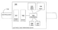
- FIG. 1is a block diagram illustrating one embodiment of the present invention.
- Electrical asset monitoring device 100is shown as being coupled to an exemplary electrical asset (e.g., a power line) 110 , via a mechanical clamping mechanism or any other means known to those of ordinary skill in the art.
- Electrical asset monitoring device 100includes a power supply 101 for extracting and storing energy from the electrical asset 110 in order to supply operating power to device 100 .
- Power supply 101may be coupled to electrical asset 110 via a direct electrical coupling, an inductive coupling, a capacitive coupling, or by any other means known to those of ordinary skill in the art.
- Power supply 101is also electrically coupled (not shown in FIG. 1 ) to components 102 - 107 of monitoring device 100 .
- Sensor 102obtains data corresponding to operating conditions of electrical asset 110 .
- the data obtained by sensor 102may comprise a voltage waveform, a current waveform, or a phase signal of electricity being transmitting by electrical asset 110 .
- sensor 102may obtain data corresponding to a current waveform
- a separate sensor(not shown in FIG. 1 ) may obtain data corresponding to a voltage waveform
- on-board processor 105may calculate the phase waveform.
- the phase waveformmay be a phase difference between the voltage and current waveforms over time, for example. Alternately, the phase waveform calculation may be performed by an off-board central processor (not shown in FIG. 1 ).
- Other measurements that may be gathered by sensor 102include a temperature and/or frequency of electrical asset 100 .
- Sensor 102may be either an analog or a digital sensor. If sensor 102 is an analog sensor, however, either processor 105 or a separate analog-to-digital converter (not shown in FIG. 1 ) may digitize the analog data from sensor
- globally synchronized timer 104is provided to obtain a timing signal that is synchronized with the other monitoring devices.
- Globally synchronized timer 104may include a global positioning system (GPS) receiver that receives a globally synchronized time as well as a local timer that is tuned to the GPS timing signal. Accordingly, in the event that the GPS receiver is not able to find a GPS signal, the local timer is able to provide a substantially synchronized timing signal until it is able to re-synchronize with the GPS signal.
- GPS receiver of globally synchronized timer 104may also be used to obtain a plurality of coordinates corresponding to the location of monitoring device 100 .
- Data obtained by sensor 102may be time-stamped by on-board processor 105 with the timing signal obtained from globally synchronized timer 104 (i.e., either from a GPS receiver or a local timer synched to the GPS receiver).
- the time-stamped datamay then be transmitted to a gateway (not shown in FIG. 1 ) from monitoring device 100 via mesh network radio 103 .
- Mesh network radio 103may also receive communications from other monitoring devices (not shown in FIG. 1 ) requesting that their respective data be relayed to a gateway (not shown in FIG. 1 ). Accordingly, mesh network radio 103 relays such communications according to efficient communication paths.
- Mesh network radio 103may be configured to operate using a Zigbee protocol, a Wi-Fi protocol, Wi-Max protocol or any other mesh network configuration capable of self-configuration and dynamic load-balancing, whereby efficient communication paths among network participants (i.e., monitoring devices and gateways) are automatically determined among the participants. Alternately, static, predetermined communication paths may be obtained and programmed into mesh network radio 103 , whereby mesh network 103 relays communications according to the predetermined paths. Further, if a Zigbee protocol is being used, it may be desirable to boost the output power of mesh network radio 103 to 1 watt (i.e., both receiver and transmitter), thereby increasing the communications range of monitoring device 100 . In addition, the data transmitted by the radio 103 may include an error correction code (ECC) to make the transmission more robust. Monitoring device 100 may also include memory 107 for storing the time-stamped data, if desired.
- ECCerror correction code
- processor 105may detect an abnormal operating condition of electrical asset 110 based on the data collected by sensor 102 . This may be done, for example, by comparing sensed data with either a predetermined threshold, or an operating point, which may be a moving average of the sensed data. Accordingly, mesh network radio 103 may be configured to transmit sensed data only when an abnormal operating condition is detected by processor 105 . Alternately, sensed data corresponding to all conditions of electrical asset 110 —including both abnormal and normal conditions—may be transmitted by mesh network radio 103 .
- monitoring device 100may include memory 106 for storing a plurality of fault signatures corresponding to a number of different fault types (e.g., lightning strike, downed wire, line-to-line fault, etc.).
- Fault signatures stored by memory 106may be any number of exemplary fault signals developed to mimic real fault conditions and are available for licensing from various institutions, such as Texas A&M University, for example.
- on-board processor 105may correlate data corresponding to an abnormal condition of electrical asset 110 to the plurality of fault signatures stored by memory 106 . Based on the correlation, processor 105 may be able to identify a probable fault type corresponding to the abnormal condition.
- the fault type identifying the abnormal condition, the time-stamped data corresponding to the abnormal condition, and the plurality of GPS coordinates corresponding to the location of monitoring device 100may be transmitted by mesh network radio 103 .
- any number of encryption schemes known to those of ordinary skill in the artmay be implemented for encrypting communications to and/or from mesh network radio 103 .
- encryptionmay be performed according to the advanced encryption standard (AES), the data encryption standard (DES), Triple DES, Blowfish, or Twofish algorithms, where the encryption key may be obtained via tree-group Diffie-Hellman (TGDH), the RSA protocol, or an elliptic-curve cryptography protocol.
- processor 105may encrypt data that is transmitted by mesh network radio 103 , including the fault location, the fault type, and time-stamped data corresponding to the fault.
- data corresponding to normal operating conditionsmay also be encrypted according to a desirable encryption scheme prior to being transmitted by mesh network radio 103 .
- FIG. 2illustrates an exemplary monitoring device 200 that may be coupled to power line 202 .
- Exemplary monitoring device 200includes current transformer 201 inductively coupled to power line 202 for providing a stepped-down current signal for current sensing and/or providing operating power.
- Current transformer 201steps down the current supplied by electrical asset 202 by a predetermined ratio to provide a current signal that is within an operating range of analog-to-digital converter 203 .
- the current signalmay also be filtered by a conditioning circuit (e.g. a low-pass filter) (not shown in FIG. 2 ) to remove high frequency noise from the current signal.
- a conditioning circuite.g. a low-pass filter
- Resistors 220 , 221 , and 222comprise a voltage divider for providing a desirably scaled signal to analog-to-digital converter 203 .
- Power supply 210(shown in phantom) includes high potential node 211 (for providing an operating voltage, e.g. V cc ), common potential node 212 (for providing a reference potential, e.g. ground), voltage regulator 215 (to maintain a constant operating voltage), energy storage capacitor 214 (for providing operating power in the case of an outage on the electrical asset being monitored), and Zener diode 213 (for voltage regulation and transient protection across capacitor 214 ). As shown in FIG.
- current transformer 201is a split-core transformer coupled, inductively, to power line 202 .
- any other current transformersmay be used, such as a closed-core current transformer, for example.
- Alternative embodiments of the inventionmay use a potential transformer, a Hall effect sensor, a Rogowski coil, or an optoelectronic sensor including, for example, a Kerr cell, a Pockels cell and/or a Faraday-effect sensor for sensing voltage and/or current waveforms of electric power line 202 .
- the exemplary monitoring device 200may include protection circuitry, in addition to the Zener diode 213 , to shield the device 200 from transient voltage and current spikes which may occur, for example, during a lightning strike.
- Digitized data from analog-to-digital converter 203is time-stamped by processor 204 with a timing signal provided by timing module 206 .
- Timing module 206may include a local timer synched to a timing signal provided by a GPS receiver, as described above. This GPS receiver may also provide coordinates identifying the location of monitoring device 200 .
- the device 200may have an identifier by which its position is known to the central command center and this identifier may be transmitted to the command center. If both the identifier and the GPS coordinates are sent, the command center may be able to determine if the device 200 has moved from its assigned location.
- Processor 204may perform other functions, such as encrypting the time-stamped data, for example.
- processor 204may be a digital signal processor (DSP), capable of sampling data from sensor 201 128 times per 60 Hz power cycle, for example.
- DSPdigital signal processor
- Processor 204may also detect an abnormal condition of power line 202 by comparing the time-stamped data to an operating point of power line 202 , which may be a moving average of sensed data or a predetermined threshold, for example.
- Processor 204is also coupled to a non-volatile memory (not shown) which stores the digitized and time-stamped data. If, due to a loss of power, this data cannot be transmitted proximate in time to the occurrence of the fault, it may be stored in the non-volatile memory and transmitted when power is restored.
- Digitized, time-stamped data from processor 204may then be transmitted by mesh network radio 205 . If provided, GPS coordinates and/or an identifier, identifying the location of monitoring device 200 may also be included with mesh network radio 205 transmissions.
- Mesh network radio 205is configured to transmit and relay messages to one or more gateways according to dynamically calculated efficient communication paths, and may be a Zigbee radio, a Wi-Max radio or a Wi-Fi radio. If radio 205 is a Wi-Fi radio, it may be programmed to operate in ad-hoc mode, where the efficient communication paths are coordinated by an ad-hoc on-demand distance vector (AODV) algorithm.
- AODVad-hoc on-demand distance vector
- FIG. 3illustrates an electrical infrastructure monitoring system in which exemplary electrical asset monitors 301 , 302 , and 303 , such as the monitoring devices described above, may be implemented for monitoring electric lines 311 , 312 , and 313 , respectively, in electricity distribution infrastructure 300 .
- Electrical asset monitors 321 , 322 , and 323may be used for monitoring electric asset 320 .
- Monitors 301 - 303 and 321 - 323are coupled to electric lines 311 - 313 and electric asset 320 , respectively, and each includes a sensor for obtaining voltage, current, and/or phase waveforms from the electric line.
- Each of monitors 301 - 303 and 321 - 323also includes a mesh network radio for transmitting and relaying communications to gateway 310 , a globally synchronized timer for time-stamping data obtained by the sensor, and a power supply coupled to the electric line for obtaining operating energy from the electric line.
- Monitors 301 - 303 and 321 - 323may also include a power storage device for at least temporarily providing operating power in the event of a power outage.
- gateway 310is one of a plurality of gateways configured to receive communications from a plurality of monitoring devices including, among others (not shown in FIG. 3 ), monitors 301 - 303 and 321 - 323 .
- gateway 310may include a mesh network radio for receiving communications via a mesh network in which the plurality of monitoring devices and gateways may be participants.
- Gateway 310may also include a network interface for relaying communications received from the monitoring devices via the mesh network to a central command center via a network distinct from the mesh network.
- gateway 310may receive communications from monitors 301 - 303 and 321 - 323 via the mesh network and re-transmit those communications via the network interface, which may be, for example, a modem configured for communication with the central command center over a global information network (e.g. the Internet).
- the network interfacemay be a modem configured to broadcast the communication over an existing radio channel used by an electric utility company in charge of electricity distribution infrastructure 300 .
- the network interfacemay be a light-emitting diode or a laser for communicating over an optical fiber.
- the network interfacemay be a modem configured for communication across a leased common-carrier link.
- communications from monitors 301 - 303 and 321 - 323may be encrypted according to an encryption scheme, which may include AES, DES, triple DES, Blowfish, or Twofish for encrypting communications using a private key obtained via TGDH, an RSA protocol, or an elliptic-curve cryptography protocol, for example.
- monitors 301 - 303 and 321 - 323may include a processor configured to implement the encryption scheme and encrypt communications to gateway 310 .
- Gateway 310may also include a processor configured to implement the encryption scheme and decrypt communications from monitors 301 - 303 and 321 - 323 .
- Gateway 310may also be configured to implement a second encryption scheme for encrypting communications to the central command center.
- the second encryption schememay either be the same as or different from the first encryption scheme.
- the central command center(not shown in FIG. 3 ) is configured to implement the second encryption scheme for decrypting communications from gateway 310 and any other gateways in the system (not shown in FIG. 3 ).
- the central command center(not shown in FIG. 3 ) is operated by an electric utility company, or any other entity that manages and monitors the electricity distribution infrastructure, and may include a network interface for communicating with gateway 310 and the other gateways in the system.
- the command centeralso includes a memory for storing a database of fault signatures, a second memory for storing sensor data originating from monitors 301 - 303 , 321 - 323 , and any other monitoring devices in the system, and a processor for analyzing the sensor data in order to identify a fault, a probable fault type, a probable fault location, and a fault response.
- the central command centermay identify a fault by comparing sensor data for electrical assets being monitored to expected operating point(s) for those electrical assets. Accordingly, if the sensor data indicates that an electrical asset is operating at a certain percentage above or below the operating point, then the central command center may determine that the electrical asset has a fault.
- the operating point for each electrical assetmay be obtained, for example, by taking a moving average of sensor data for the electrical asset when it is operating in a normal condition. If a fault is identified at any of the electrical assets, the probable fault type of the fault may be determined by correlating the sensor data to a number of fault signatures in the database of fault signatures.
- the fault signaturescorrespond to a number of different fault types (e.g., lightning strike, downed wire, line-to-line fault, etc.), and are exemplary fault signals developed to mimic real fault conditions.
- Databases of fault signaturesmay be available for licensing from various institutions, such as Texas A&M University, for example.
- monitoring devices located physically close to one anothere.g., within a 1 mile radius
- sensor data from each of monitoring devicesmay be correlated to the fault signatures in order to identify the probable fault type.
- a weighted average of correlation valuesmay be calculated, with the fault signature correlation value for a monitoring device that detected the fault first being given a highest weight and the fault signature correlation value for a monitoring device that detected the fault last being given a lowest weight.
- M 1 -M 5may detect the fault, with M 1 detecting the fault first, M 2 detecting the fault second, M 3 detecting the fault third, M 4 detecting the fault fourth, and M 5 detecting the fault last.
- correlation values C 1 -C 5are obtained by correlating sensor data from each of M 1 -M 5 , respectively.
- a final correlation value, C finalfor the detected fault may be obtained, therefore, by obtaining a weighted average of C 1 -C 5 based on the sequence in which M 1 -M 5 detected the fault.
- the final correlation valueis obtained according to any predetermined weighting scheme, which, for the present example, may be:
- C finalw 1 ⁇ C 1 + w 2 ⁇ C 2 + w 3 ⁇ C 3 + w 4 ⁇ C 4 + w 5 ⁇ C 5 w 1 + w 2 + w 3 + w 4 + w 5 , where w 1 -w 5 are the predetermined weighting values.
- a fault type corresponding to the fault signature with the highest final correlation valuemay be designated as the probable fault type.
- FIG. 4illustrates an exemplary electricity distribution infrastructure 400 employing monitors s 1 -s 7 for monitoring electrical lines 411 - 416 .
- Each of electrical lines 411 - 416may have differing characteristics, including, for example, a propagation velocity.
- the central command centermay also include a memory for storing a database of electrical asset (i.e., electrical lines in the present embodiment) characteristics including, for example, propagation velocities.
- electrical lines 411 , 413 , and 416may have propagation velocity v 1
- line 412may have propagation velocity v 2
- lines 414 and 415may have propagation velocity v 3
- An abnormal condition on at least line 411may arise at time, t 0 , due to fault 401 at fault location 410 .
- Fault 401also causes fault waveforms 402 and 403 , with fault waveform 402 traveling toward monitor s 1 and fault waveform 403 traveling toward monitor s 7 .
- Monitor s 7detects fault waveform 403 at time t 7 and monitor 51 detects fault waveform 402 at time t 1 .
- monitors s 1 and s 7sense and record data corresponding to fault waveforms 402 and 403 , respectively.
- the data corresponding to fault waveforms 402 and 403are also time-stamped with times t 1 and t 7 , respectively, where times t 1 and t 7 are obtained according to a globally synchronized timer.
- the globally synchronized timermay obtain the globally synchronized time from a GPS receiver, for example, where there may be desirably negligible timing error between monitors s 1 -s 7 .
- sensor s 1 time-stampssensed data with t 1 and not with some erroneous time, t 1 +error 1 .
- a GPS receivermay also be able to provide monitors s 1 -s 7 with GPS coordinates identifying a global location of sensors s 1 -s 7 .
- Monitors s 1 and s 7may transmit, to the central command center, the time-stamped data corresponding to fault waveforms 402 and 403 , as well as the GPS coordinates that identify their respective global locations.
- the central command centermay then determine a probable location of fault 401 by analyzing the data to determine the distance ds 7 of fault location 410 from monitor s 7 , and distance ds 1 of fault location 410 from monitor s 1 .
- the central command centermay then perform the following exemplary calculation procedure to identify the probable fault location.
- ds 7v 1 ⁇ (t 7 ⁇ t 0 ), where ds 7 is an unknown distance between monitor s 7 and fault location 410 , v 1 is a known propagation velocity of line 411 , t 7 is a known time at which fault waveform 403 is detected, and t 0 is an unknown time at which fault 401 occurs.
- d 11v 1 ⁇ (t 1 +t 7 ⁇ 2 ⁇ (t 1 ⁇ ds 1 /v 1 ))
- d 11v 1 ⁇ t 7 ⁇ v 1 ⁇ t 1 +2 ⁇ ds 1
- d 11 , v 1 , t 7 , and t 1are known values.
- the central command centermay solve for ds 1 and ds 7 , thereby identifying the probable fault location.
- Those of ordinary skill in the artwill be able to perform similar calculations to identify probable fault locations for faults originating on any of lines 411 - 416 .
- a fault responsemay be assigned and initiated once the central command center has identified identify a fault, a probable fault type, and a probable fault location.
- the fault responsemay be a warning that includes the probable fault location and the probable fault type.
- the fault warningmay be, for example, a fax message, an e-mail message, a pager message, an audiovisual warning, a network alert, an SMS message, and/or a Simple Object Access Protocol (SOAP) message.
- SOAPSimple Object Access Protocol
- the central command centermay initiate a power factor correction algorithm, which may include, for example, switching on any number of capacitor banks, or any other power factor correction method known by those of ordinary skill in the art.
- the fault responsemay be to initiate an electrical asset isolation algorithm.
- Such an algorithmmay switch the faulted electrical asset out of the electricity distribution infrastructure, thereby preventing the possible spread of the fault condition to other electrical assets.
- the fault responsemay be to initiate an electrical asset bypass algorithm.
- Such an algorithmmay direct electricity distribution around the overloaded asset, or switch in additional electrical assets into the electricity distribution infrastructure, thereby preventing a fault from occurring at the overloaded asset.
- the electrical asset bypass algorithmmay control the source of the overloading in order to reduce the load on the electrical asset. For example, if the source of overloading includes an air conditioning system of a large office building, then the algorithm may have control over the thermostat of the large office building in order to reduce the load in peak conditions.
- monitors 321 - 323may be used to monitor electricity consumption of substation 320 , which may be a residential distribution station, for example.
- substation 320may include one or more electric meters for logging electricity consumption.
- electric utility personneldrive to, and manually interrogate the electric meters in order to obtain the logged electricity consumption data.
- one embodiment of the present inventionincludes electric meters that are configured to transmit the logged electricity consumption data to the central command center via the mesh network.
- Electric meters in the present embodimentmay include a mesh network radio for communicating via the mesh network and a globally synchronized timer for time-stamping the consumption data.
- the central command centermay receive time-stamped observed consumption data from the electric meters as well as time-stamped actual consumption data from monitors 321 - 323 .
- the command centermay then compare the observed and actual consumption values over time in order to determine whether an error exists at any of the electric meters.
- a theft monitormay be alerted, when the magnitude of any such error exceeds some predetermined threshold. For example, if an electric meter indicates that consumption is some percentage below an actual consumption value (e.g., 50% of actual consumption), then an assumption may be made that someone has altered the electric meter in order to steal electricity. Accordingly, the theft monitor may assign an investigator to investigate the assumed theft, generate a bill based on the actual consumption value, or assign a repair crew to repair the electric timer.
- FIG. 5illustrates an exemplary mesh network 500 formed according to one embodiment of the present invention and including gateways 501 - 505 and electric asset monitors 510 - 535 .
- a plurality of direct communication linksare shown as formed between monitors and between certain monitors and gateways.
- the mesh networkcoordinates efficient communication paths among the electrical asset monitors and the one or more gateways.
- electrical asset monitor 531may transmit data to gateway 501 according to efficient path 550 , whereby communications are routed through electrical asset monitor 524 to monitor 518 , monitor 518 to monitor 515 , and monitor 515 to gateway 501 .
- the most efficient path to a gatewaymay not necessarily be the shortest path.
- a failure of the monitorsmay arise from a power outage that results in one or more monitors dropping out of the network. Alternately, the failure may arise from one or more monitors being congested with network traffic, causing an undesirable slowing of communications to and from the congested monitors.
- monitor 531may transmit data according to alternate efficient path 555 . Alternate efficient path 555 may route data from monitor 531 through monitor 532 to monitor 525 , monitor 525 to monitor 520 , monitor 520 to monitor 511 , and monitor 511 to gateway 503 .
- the mesh networkmay be configured according to the ZigBee protocol.
- the mesh networkmay be configured according to an ad-hoc Wi-Fi protocol, where efficient communication paths are determined and coordinated according to an ad-hoc on-demand distance vector (AODV) algorithm, as known by those of ordinary skill in the art.
- AODVad-hoc on-demand distance vector
- step 601by obtaining data from an analog sensor (i.e., the monitoring element) corresponding to a current waveform, a voltage waveform, and/or a phase waveform of the electrical asset being monitored.
- Step 602then digitizes the analog data (i.e., the sensed waveform(s)) into a digital signal.
- Optional step 603may then encrypt the digital signal according to an encryption scheme, as described above.
- Step 604may transmit the optionally encrypted digital signal through a mesh network, where the transmission is routed to a gateway based on a most efficient path.
- a further step(not shown in FIG. 6 ) may be performed in parallel with steps 601 - 604 and may include relaying, according to a most efficient path, other encrypted digital signals from other monitoring elements, where the other monitoring elements are monitoring other electrical assets.
- the processmay also include the step of extracting and storing operational power from the electrical asset being monitored.
- the processmay also include the step of receiving a globally synchronized time for synching a local timer and a plurality of coordinates corresponding to a position of the monitoring element. Once the globally synchronized time is received, the process may then time-stamp the sensed waveforms according to the local timer. In the present embodiment, the process may also encrypt the plurality of coordinates corresponding to the position of the monitoring element, and transmit the encrypted coordinates along with the time-stamped, encrypted waveform data. As described above, the device may alternatively or in addition transmit an identifier by which its position is known to the command center.
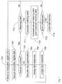
- FIG. 7is a flow-chart illustrating a process according to yet another embodiment of the present invention.
- the processis for managing one or more electrical assets that define an electrical infrastructure, such as a power grid, for example.
- the processmay begin with step 701 , which receives, from one or more gateways, encrypted data corresponding to one or more of a current, a voltage, and/or a phase angle waveform sensed by a plurality of electrical asset monitors in the electrical infrastructure.
- Each one of the electrical asset monitors in the electrical infrastructuremay be coupled to an electrical asset (e.g., a power line) to monitor an operating condition of the electrical asset.
- an electrical assete.g., a power line
- Step 702may then decrypt the encrypted data to obtain the sensed waveform(s), where the waveforms are synchronized according to a globally synchronized timer and may further include a plurality of coordinates identifying a source location of each waveform.
- the coordinatesmay be GPS coordinates, for example or coordinates provided by a central database based on a received identifier.
- the decryptionmay be performed according to the advanced encryption standard (AES).
- Step 703may then determine, based on the plurality of sensed waveforms and respective source locations, operating conditions for each of the electrical assets being managed.
- AESadvanced encryption standard
- the operating condition for an electrical assetmay be compared to an expected value (i.e., an operating point, which may be obtained, for example, by taking a moving average of the operating condition of a given electrical asset) in order to determine whether the electrical asset is operating under a normal condition or an abnormal condition.
- an expected valuei.e., an operating point, which may be obtained, for example, by taking a moving average of the operating condition of a given electrical asset
- step 704calculates a probable fault type and a probable fault location of a fault that may be causing the abnormal condition.
- the calculationsmay be performed based on the sensed waveform data and the source locations of any number of electrical asset monitors that sensed the abnormal condition, in addition to a database having a number of electrical asset parameters/characteristics.
- the electrical asset parameters databasemay include, for example, a propagation velocity of the electrical asset, which may be used to calculate the probable fault location as described above with reference to FIG. 4 .
- the probable fault typemay be determined by correlating the sensed waveform with a database of fault signatures, where a fault signature that has the highest correlation with the sensed waveform corresponds to the probable fault type. If multiple monitors detected the fault, then there may be multiple sensed waveforms that correspond to the fault and, accordingly, the probable fault type may be based on a weighted average of the correlations of each sensed waveform to the fault signature database, as described above.
- Step 705may then assign a fault response based on the probable fault type and the probable fault location.
- step 705may assign a fault warning for a momentary fault, a temporary fault, or an incipient fault. This may include, for example, generating a SOAP message having the probable fault type and probable fault location and transmitting the SOAP message according to a SOAP notification interface.
- step 705may assign a power factor correction algorithm when the probable fault type is an unbalance power factor fault.
- the power factor correction algorithmmay include, for example, engaging any number of capacitor banks or other reactive elements.
- step 705may assign an electrical asset isolation algorithm when the probable fault type is an electrical asset failure fault.
- the isolation algorithmmay include, for example, opening any number of switches around the electrical asset in order to isolate the fault from spreading throughout the electrical infrastructure.
- step 705may assign an electrical asset bypass algorithm when the probable fault type is an electrical asset overload fault.
- the bypass algorithmmay include, for example, opening or closing any number of switches around the electrical asset, thereby allowing other electrical assets to pick up some portion of the load on the overloaded electrical asset.
- any number of devices that may be causing the overload faulte.g., factories, large office building climate control, etc.
- may be controlled to lower the loade.g., affecting the thermostat for a large office building).
- step 703a normal operating condition of the electrical asset is detected, the process may either terminate (not shown in FIG. 7 ), restart at step 701 (not shown in FIG. 7 ), or move to step 710 , which determines whether any measured metering data was received for the electrical asset. If metering data was not received, the process may either terminate (not shown in FIG. 7 ) or restart at step 701 . If metering data was received, however, the process may proceed to step 711 , which calculates, based on the sensed waveform data, actual metering data for an electric meter that originated the measured metering data. Though not shown in FIG.
- step 712may compare the calculated, actual metering data and the measured metering data to determine whether an error exists at any of the electric meters.
- step 712may also determine the magnitude of any determined error.
- Step 713may determine whether the magnitude of the error is greater than some threshold. If it is not, the process may either terminate (not shown in FIG. 7 ) or restart at step 701 . If the error is greater than the threshold, then step 714 may alert a theft monitor, which may then investigate the error, send a repair crew to fix the error, or generate a bill based on the actual metering data.
Landscapes
- Physics & Mathematics (AREA)
- General Physics & Mathematics (AREA)
- Engineering & Computer Science (AREA)
- Power Engineering (AREA)
- Mathematical Physics (AREA)
- Theoretical Computer Science (AREA)
- Remote Monitoring And Control Of Power-Distribution Networks (AREA)
Abstract
Description
where w1-w5are the predetermined weighting values. A fault type corresponding to the fault signature with the highest final correlation value may be designated as the probable fault type.
Claims (14)
Priority Applications (1)
| Application Number | Priority Date | Filing Date | Title |
|---|---|---|---|
| US12/756,256US8587445B2 (en) | 2006-09-13 | 2010-04-08 | Monitoring electrical assets for fault and efficiency correction |
Applications Claiming Priority (2)
| Application Number | Priority Date | Filing Date | Title |
|---|---|---|---|
| US11/520,368US7714735B2 (en) | 2005-09-13 | 2006-09-13 | Monitoring electrical assets for fault and efficiency correction |
| US12/756,256US8587445B2 (en) | 2006-09-13 | 2010-04-08 | Monitoring electrical assets for fault and efficiency correction |
Related Parent Applications (1)
| Application Number | Title | Priority Date | Filing Date |
|---|---|---|---|
| US11/520,368DivisionUS7714735B2 (en) | 2005-09-13 | 2006-09-13 | Monitoring electrical assets for fault and efficiency correction |
Publications (2)
| Publication Number | Publication Date |
|---|---|
| US20100188239A1 US20100188239A1 (en) | 2010-07-29 |
| US8587445B2true US8587445B2 (en) | 2013-11-19 |
Family
ID=42353738
Family Applications (2)
| Application Number | Title | Priority Date | Filing Date |
|---|---|---|---|
| US11/520,368Active - Reinstated2028-07-25US7714735B2 (en) | 2005-09-13 | 2006-09-13 | Monitoring electrical assets for fault and efficiency correction |
| US12/756,256Active2029-01-19US8587445B2 (en) | 2006-09-13 | 2010-04-08 | Monitoring electrical assets for fault and efficiency correction |
Family Applications Before (1)
| Application Number | Title | Priority Date | Filing Date |
|---|---|---|---|
| US11/520,368Active - Reinstated2028-07-25US7714735B2 (en) | 2005-09-13 | 2006-09-13 | Monitoring electrical assets for fault and efficiency correction |
Country Status (1)
| Country | Link |
|---|---|
| US (2) | US7714735B2 (en) |
Cited By (28)
| Publication number | Priority date | Publication date | Assignee | Title |
|---|---|---|---|---|
| CN104330701A (en)* | 2014-11-06 | 2015-02-04 | 扬州森源电气有限公司 | Single-phase fault monitoring wireless system for community and monitoring method thereof |
| US20150309094A1 (en)* | 2014-04-25 | 2015-10-29 | Loris Morassutto | System and method for measuring active power in a load without a load voltage |
| US9247378B2 (en) | 2012-08-07 | 2016-01-26 | Honeywell International Inc. | Method for controlling an HVAC system using a proximity aware mobile device |
| US9477239B2 (en) | 2012-07-26 | 2016-10-25 | Honeywell International Inc. | HVAC controller with wireless network based occupancy detection and control |
| US9477241B2 (en) | 2013-11-22 | 2016-10-25 | Honeywell International Inc. | HVAC controller with proximity based message latency control |
| US9560482B1 (en) | 2015-12-09 | 2017-01-31 | Honeywell International Inc. | User or automated selection of enhanced geo-fencing |
| US9562925B2 (en) | 2012-02-14 | 2017-02-07 | Tollgrade Communications, Inc. | Power line management system |
| US9587848B2 (en) | 2013-12-11 | 2017-03-07 | Honeywell International Inc. | Building automation controller with rear projecting light |
| US9609478B2 (en) | 2015-04-27 | 2017-03-28 | Honeywell International Inc. | Geo-fencing with diagnostic feature |
| US9628951B1 (en) | 2015-11-11 | 2017-04-18 | Honeywell International Inc. | Methods and systems for performing geofencing with reduced power consumption |
| US9647454B2 (en) | 2011-08-31 | 2017-05-09 | Aclara Technologies Llc | Methods and apparatus for determining conditions of power lines |
| US9825463B2 (en) | 2015-02-12 | 2017-11-21 | The Mitre Corporation | Devices and systems for distributed power-grid monitoring |
| US9860697B2 (en) | 2015-12-09 | 2018-01-02 | Honeywell International Inc. | Methods and systems for automatic adjustment of a geofence size |
| US9900174B2 (en) | 2015-03-06 | 2018-02-20 | Honeywell International Inc. | Multi-user geofencing for building automation |
| US9967391B2 (en) | 2015-03-25 | 2018-05-08 | Honeywell International Inc. | Geo-fencing in a building automation system |
| US9972989B2 (en) | 2014-03-31 | 2018-05-15 | Aclara Technologies Llc | Optical voltage sensing for underground medium voltage wires |
| US10018372B2 (en) | 2013-11-22 | 2018-07-10 | Honeywell International Inc. | Method to control a communication rate between a thermostat and a cloud based server |
| US10057110B2 (en) | 2015-11-06 | 2018-08-21 | Honeywell International Inc. | Site management system with dynamic site threat level based on geo-location data |
| US10203355B2 (en) | 2014-08-29 | 2019-02-12 | Aclara Technologies Llc | Power extraction for a medium voltage sensor using a capacitive voltage divider |
| US10306403B2 (en) | 2016-08-03 | 2019-05-28 | Honeywell International Inc. | Location based dynamic geo-fencing system for security |
| US10302322B2 (en) | 2016-07-22 | 2019-05-28 | Ademco Inc. | Triage of initial schedule setup for an HVAC controller |
| US10317102B2 (en) | 2017-04-18 | 2019-06-11 | Ademco Inc. | Geofencing for thermostatic control |
| US10488062B2 (en) | 2016-07-22 | 2019-11-26 | Ademco Inc. | Geofence plus schedule for a building controller |
| US10516965B2 (en) | 2015-11-11 | 2019-12-24 | Ademco Inc. | HVAC control using geofencing |
| US10605472B2 (en) | 2016-02-19 | 2020-03-31 | Ademco Inc. | Multiple adaptive geo-fences for a building |
| US10802469B2 (en) | 2015-04-27 | 2020-10-13 | Ademco Inc. | Geo-fencing with diagnostic feature |
| US10802459B2 (en) | 2015-04-27 | 2020-10-13 | Ademco Inc. | Geo-fencing with advanced intelligent recovery |
| US10928087B2 (en) | 2012-07-26 | 2021-02-23 | Ademco Inc. | Method of associating an HVAC controller with an external web service |
Families Citing this family (168)
| Publication number | Priority date | Publication date | Assignee | Title |
|---|---|---|---|---|
| US7444401B1 (en) | 2002-11-18 | 2008-10-28 | Arkion Systems Llc | Method and apparatus for inexpensively monitoring and controlling remotely distributed appliances |
| US9557723B2 (en) | 2006-07-19 | 2017-01-31 | Power Analytics Corporation | Real-time predictive systems for intelligent energy monitoring and management of electrical power networks |
| US20170046458A1 (en) | 2006-02-14 | 2017-02-16 | Power Analytics Corporation | Systems and methods for real-time dc microgrid power analytics for mission-critical power systems |
| US20160246905A1 (en) | 2006-02-14 | 2016-08-25 | Power Analytics Corporation | Method For Predicting Arc Flash Energy And PPE Category Within A Real-Time Monitoring System |
| US9092593B2 (en) | 2007-09-25 | 2015-07-28 | Power Analytics Corporation | Systems and methods for intuitive modeling of complex networks in a digital environment |
| US8131401B2 (en)* | 2006-07-19 | 2012-03-06 | Power Analytics Corporation | Real-time stability indexing for intelligent energy monitoring and management of electrical power network system |
| KR100850202B1 (en)* | 2006-03-04 | 2008-08-04 | 삼성전자주식회사 | Cryptographic method for countering DFA using ECC fast Montgomery power ladder algorithm |
| US7786894B2 (en)* | 2006-06-20 | 2010-08-31 | Battelle Energy Alliance, Llc | Methods, apparatus, and systems for monitoring transmission systems |
| US7609158B2 (en)* | 2006-10-26 | 2009-10-27 | Cooper Technologies Company | Electrical power system control communications network |
| US20080249826A1 (en)* | 2007-03-26 | 2008-10-09 | Jeff Tolnar | System and method for integrated asset protection |
| DE202008009128U1 (en)* | 2007-07-06 | 2009-01-02 | Aizo Ag | Consumption and state meter |
| CA2698606A1 (en)* | 2007-09-24 | 2009-04-02 | Edsa Micro Corporation | Real-time stability indexing for intelligent energy monitoring and management of electrical power network system |
| US9383394B2 (en)* | 2007-11-02 | 2016-07-05 | Cooper Technologies Company | Overhead communicating device |
| US7930141B2 (en)* | 2007-11-02 | 2011-04-19 | Cooper Technologies Company | Communicating faulted circuit indicator apparatus and method of use thereof |
| US8594956B2 (en)* | 2007-11-02 | 2013-11-26 | Cooper Technologies Company | Power line energy harvesting power supply |
| US8067946B2 (en) | 2007-11-02 | 2011-11-29 | Cooper Technologies Company | Method for repairing a transmission line in an electrical power distribution system |
| US20120105227A1 (en)* | 2008-04-24 | 2012-05-03 | Rite-Solutions, Inc. | Distributed sensor network using existing infrastructure |
| US8255692B2 (en)* | 2008-07-11 | 2012-08-28 | Rosemount Inc. | Method of providing secure tamper-proof acquired data from process instruments |
| US8665102B2 (en)* | 2008-07-18 | 2014-03-04 | Schweitzer Engineering Laboratories Inc | Transceiver interface for power system monitoring |
| JP2012507090A (en) | 2008-10-27 | 2012-03-22 | ミューラー インターナショナル エルエルシー | Infrastructure monitoring system and method |
| AU2014259545B2 (en)* | 2008-10-27 | 2015-08-06 | Mueller International Llc | Infrastructure monitoring system and method |
| NL2002457C2 (en)* | 2009-01-27 | 2010-07-28 | Liandon B V | END-USER ELECTRICITY NETWORK, USE, METHOD AND COMPOSITION. |
| US9678114B2 (en) | 2009-04-16 | 2017-06-13 | Panoramic Power Ltd. | Apparatus and methods thereof for error correction in split core current transformers |
| CN102460188B (en) | 2009-04-16 | 2015-09-16 | 全景电力有限公司 | Device and method for power consumption measurement at circuit breaker point |
| US9134348B2 (en) | 2009-04-16 | 2015-09-15 | Panoramic Power Ltd. | Distributed electricity metering system |
| EP2433440B1 (en) | 2009-05-22 | 2018-07-25 | Mueller International, LLC | Infrastructure monitoring devices, systems, and methods |
| US8954203B2 (en)* | 2009-06-24 | 2015-02-10 | Tigo Energy, Inc. | Systems and methods for distributed power factor correction and phase balancing |
| US8509954B2 (en) | 2009-08-21 | 2013-08-13 | Allure Energy, Inc. | Energy management system and method |
| US9838255B2 (en) | 2009-08-21 | 2017-12-05 | Samsung Electronics Co., Ltd. | Mobile demand response energy management system with proximity control |
| US8498749B2 (en) | 2009-08-21 | 2013-07-30 | Allure Energy, Inc. | Method for zone based energy management system with scalable map interface |
| US9209652B2 (en) | 2009-08-21 | 2015-12-08 | Allure Energy, Inc. | Mobile device with scalable map interface for zone based energy management |
| EP2293411B1 (en)* | 2009-09-03 | 2021-12-15 | TDK Corporation | Wireless power feeder and wireless power transmission system |
| US8874277B2 (en)* | 2009-09-15 | 2014-10-28 | Denis Kouroussis | Smart-grid adaptive power management method and system with power factor optimization and total harmonic distortion reduction |
| US20110082597A1 (en) | 2009-10-01 | 2011-04-07 | Edsa Micro Corporation | Microgrid model based automated real time simulation for market based electric power system optimization |
| IL201360A (en)* | 2009-10-11 | 2014-08-31 | Moshe Henig | Loads management and outages detection for smart grid |
| DE102009057508A1 (en)* | 2009-12-10 | 2011-06-16 | Astrium Gmbh | Monitoring device for use in monitoring system for monitoring e.g. surrounding parameters in forest, has communication unit for transmitting message that comprises position information and information representing determined parameters |
| US8271216B2 (en)* | 2010-01-28 | 2012-09-18 | Maxim Integrated Products, Inc. | Isolated current sensor with codec |
| US8463483B2 (en)* | 2010-02-12 | 2013-06-11 | GM Global Technology Operations LLC | Method and system for monitoring vehicle electrical systems |
| US8731854B2 (en)* | 2010-03-31 | 2014-05-20 | Landis + Gyr, Inc. | Utility meter with wireless pulse output |
| US20110257924A1 (en)* | 2010-04-20 | 2011-10-20 | Southern California Edison | Self-monitoring and communicating transformer |
| WO2011156394A2 (en)* | 2010-06-07 | 2011-12-15 | Abb Research Ltd. | Systems and methods for classifying power line events |
| US8853886B2 (en) | 2010-06-09 | 2014-10-07 | Tigo Energy, Inc. | System for use of static inverters in variable energy generation environments |
| US8931505B2 (en) | 2010-06-16 | 2015-01-13 | Gregory E. HYLAND | Infrastructure monitoring devices, systems, and methods |
| JP5126308B2 (en)* | 2010-07-09 | 2013-01-23 | ソニー株式会社 | Power control device |
| WO2012014294A1 (en)* | 2010-07-28 | 2012-02-02 | 富士通株式会社 | Key setting method, node, and network system |
| JP5408354B2 (en)* | 2010-07-28 | 2014-02-05 | 富士通株式会社 | Key setting method, node, and network system |
| US8738318B2 (en) | 2010-08-02 | 2014-05-27 | Lindsey Manufacturing Company | Dynamic electric power line monitoring system |
| WO2012021477A1 (en) | 2010-08-10 | 2012-02-16 | Cooper Technologies Company | Apparatus and method for mounting an overhead device |
| US9282383B2 (en)* | 2011-01-14 | 2016-03-08 | Trilliant Incorporated | Process, device and system for volt/VAR optimization |
| US9589241B2 (en) | 2011-03-31 | 2017-03-07 | The United States Of America As Represented By The Secretary Of The Navy | Electrical resource controller |
| US8833390B2 (en) | 2011-05-31 | 2014-09-16 | Mueller International, Llc | Valve meter assembly and method |
| US8718833B2 (en)* | 2011-07-15 | 2014-05-06 | General Electric Company | Automated systems and methods for controlling localized load conditions to extend electrical distribution system component life |
| US9835141B2 (en)* | 2011-07-28 | 2017-12-05 | Vestas Wind Systems A/S | Wind turbine blade and a lightning measurement system therein |
| EP2751955B1 (en) | 2011-08-30 | 2019-11-13 | Samsung Electronics Co., Ltd. | Resource manager and method for communicating resource management information for smart energy and media resources |
| US8799481B2 (en) | 2011-09-14 | 2014-08-05 | General Electric Company | Method and system for detection of communication activities of a meter board |
| US9015326B2 (en) | 2011-09-14 | 2015-04-21 | General Electric Company | Method and system for managing power consumption of a meter during communication activities |
| US8719681B2 (en) | 2011-09-14 | 2014-05-06 | General Electric Company | Diagnostic tool for metrology errors caused by communication activities |
| US8982591B2 (en) | 2011-10-18 | 2015-03-17 | Tigo Energy, Inc. | System and method for exchangeable capacitor modules for high power inverters and converters |
| US8660134B2 (en) | 2011-10-27 | 2014-02-25 | Mueller International, Llc | Systems and methods for time-based hailing of radio frequency devices |
| US8855569B2 (en) | 2011-10-27 | 2014-10-07 | Mueller International, Llc | Systems and methods for dynamic squelching in radio frequency devices |
| US9590411B2 (en)* | 2011-12-15 | 2017-03-07 | Schweitzer Engineering Laboratories, Inc. | Systems and methods for time synchronization of IEDs via radio link |
| WO2013091028A1 (en)* | 2011-12-23 | 2013-06-27 | Dx Tech Pty Ltd | Fault detection system |
| KR102091222B1 (en)* | 2012-02-02 | 2020-03-20 | 오클랜드 유니서비시즈 리미티드 | Var control for inductive power transfer systems |
| WO2014053174A1 (en)* | 2012-10-03 | 2014-04-10 | Abb Technology Ltd | Method for sensing a fault in a power system based on travelling wave currents |
| ES2552829B1 (en) | 2012-10-19 | 2017-03-23 | Schweitzer Engineering Laboratories, Inc. | Time Distribution Switch |
| US9599719B2 (en) | 2012-10-19 | 2017-03-21 | Schweitzer Engineering Laboratories, Inc. | Detection of manipulated satellite time signals |
| US9716530B2 (en) | 2013-01-07 | 2017-07-25 | Samsung Electronics Co., Ltd. | Home automation using near field communication |
| US10063499B2 (en) | 2013-03-07 | 2018-08-28 | Samsung Electronics Co., Ltd. | Non-cloud based communication platform for an environment control system |
| US9784766B2 (en) | 2013-03-12 | 2017-10-10 | Lindsey Manufacturing Company | Dynamic real time transmission line monitor and method of monitoring a transmission line using the same |
| US9379556B2 (en) | 2013-03-14 | 2016-06-28 | Cooper Technologies Company | Systems and methods for energy harvesting and current and voltage measurements |
| WO2014151384A1 (en) | 2013-03-15 | 2014-09-25 | Mueller International, Llc | Systems for measuring properties of water in a water distribution system |
| US9264162B2 (en)* | 2013-05-23 | 2016-02-16 | Honeywell Limited | Wireless position-time synchronization for scanning sensor devices |
| GB2514415A (en) | 2013-05-24 | 2014-11-26 | Ralugnis As | Method and apparatus for monitoring power grid parameters |
| US9689910B2 (en)* | 2013-06-10 | 2017-06-27 | Wabtec Holding Corp. | Detecting faults in a two-wire power line |
| WO2015010743A1 (en)* | 2013-07-25 | 2015-01-29 | Siemens Aktiengesellschaft | Method and device for signaling and controlling a power grid coupling a plurality of actuators |
| CN103558509B (en)* | 2013-10-30 | 2016-04-13 | 北京交大创新科技中心 | The online Fault Locating Method of a kind of electric transmission line isolator based on zigbee |
| CN203674622U (en)* | 2013-12-04 | 2014-06-25 | 广东电网公司清远供电局 | Electric transmission line monitor system based on broadband wireless Mesh |
| CN106464551A (en) | 2014-01-06 | 2017-02-22 | 魅力能源公司 | System, device, and apparatus for coordinating environments using network devices and remote sensory information |
| SG11201605494QA (en) | 2014-01-06 | 2016-08-30 | Allure Energy Inc | System, device, and apparatus for coordinating environments using network devices and remote sensory information |
| US10495674B2 (en)* | 2014-01-29 | 2019-12-03 | Nec Corporation | Monitoring device, monitoring system, monitoring method, correction information generation device, correction information generation method, and non-transitory storage medium |
| GB2524055B (en)* | 2014-03-13 | 2017-11-15 | Cresatech Ltd | Improvements in or relating to power service monitoring |
| US9667058B2 (en) | 2014-03-17 | 2017-05-30 | Abb Schweiz Ag | Method and apparatus for sensing a fault in a power system |
| US9823277B1 (en) | 2014-03-21 | 2017-11-21 | Fiber Optic Sensor Systems Technology Corporation | Fiber optic electromagnetic phenomena sensors |
| WO2015151560A1 (en)* | 2014-03-31 | 2015-10-08 | 日本電気株式会社 | Monitoring device, monitoring system, monitoring method, and program |
| US9494249B2 (en) | 2014-05-09 | 2016-11-15 | Mueller International, Llc | Mechanical stop for actuator and orifice |
| US11150114B1 (en) | 2014-05-20 | 2021-10-19 | Smartsensecom, Inc. | Fiber optic electromagnetic phenomena sensor system |
| US10107839B1 (en) | 2014-06-12 | 2018-10-23 | Fiber Optic Sensor Systems Technology Corporation | Fiber optic sensor system for detection of electric currents and other phenomena associated with geomagnetic disturbances |
| US10240928B2 (en)* | 2014-08-25 | 2019-03-26 | Honeywell International Inc. | Systems and methods for predictive health monitoring of gyroscopes and accelerometers |
| US9565620B2 (en) | 2014-09-02 | 2017-02-07 | Mueller International, Llc | Dynamic routing in a mesh network |
| US9594112B2 (en) | 2014-09-16 | 2017-03-14 | Schweitzer Engineering Laboratories, Inc. | Fault detection in electric power delivery systems using underreach, directional, and traveling wave elements |
| JP2016075600A (en)* | 2014-10-07 | 2016-05-12 | ミドリ安全株式会社 | Current / phase measurement system |
| CN104460606B (en)* | 2014-11-14 | 2018-05-01 | 上海理工大学 | Electricity distribution power transformator remote monitoring system and method |
| US10176032B2 (en) | 2014-12-01 | 2019-01-08 | Uptake Technologies, Inc. | Subsystem health score |
| CN104502802A (en)* | 2014-12-24 | 2015-04-08 | 国家电网公司 | Method and system for recognizing lightning strike fault and lightning strike fault type of power transmission line |
| WO2016176314A1 (en)* | 2015-04-28 | 2016-11-03 | Unilectric, Llc | Apparatus for detecting faults in an electrical circuit and monitoring and controlling electrical energy consumption |
| US10205343B2 (en)* | 2015-04-28 | 2019-02-12 | Unilectric, Llc | Smart power node |
| US11064272B2 (en)* | 2015-05-13 | 2021-07-13 | Electrical Grid Monitoring Ltd. | Method and system of tethered routers |
| US11041839B2 (en) | 2015-06-05 | 2021-06-22 | Mueller International, Llc | Distribution system monitoring |
| CN104898026A (en)* | 2015-06-11 | 2015-09-09 | 国家电网公司 | Method and device for positioning of cable fault |
| US10024885B2 (en) | 2015-07-28 | 2018-07-17 | Panoramic Power Ltd. | Thermal management of self-powered power sensors |
| US9891252B2 (en) | 2015-07-28 | 2018-02-13 | Panoramic Power Ltd. | Thermal management of self-powered power sensors |
| US10310004B2 (en) | 2015-09-18 | 2019-06-04 | Schweitzer Engineering Laboratories, Inc. | Time-domain differential line protection of electric power delivery systems |
| US10090664B2 (en) | 2015-09-18 | 2018-10-02 | Schweitzer Engineering Laboratories, Inc. | Time-domain directional line protection of electric power delivery systems |
| EP3363095A4 (en)* | 2015-10-12 | 2019-08-14 | Schweitzer Engineering Laboratories, Inc. | Traveling wave directional element |
| US10564247B2 (en) | 2015-10-13 | 2020-02-18 | Schweitzer Engineering Laboratories, Inc. | Testing system for traveling wave fault detectors |
| US10564246B2 (en) | 2015-10-13 | 2020-02-18 | Schweitzer Engineering Laboratories, Inc. | Testing system for traveling wave fault detectors |
| EP3362805A4 (en) | 2015-10-13 | 2019-06-19 | Schweitzer Engineering Laboratories, Inc. | Electric power system monitoring using high-frequency signals |
| EP3362807A4 (en) | 2015-10-14 | 2019-06-26 | Schweitzer Engineering Laboratories, Inc. | High-frequency electric power system signal processing system |
| CN105513253A (en)* | 2016-03-03 | 2016-04-20 | 国网山东省电力公司郓城县供电公司 | Low-voltage distribution cabinet fire alarm system |
| US10367699B2 (en) | 2016-04-25 | 2019-07-30 | Cisco Technology, Inc. | Network architecture for predictive services management in cable network environments |
| US10348554B2 (en)* | 2016-04-25 | 2019-07-09 | Cisco Technology, Inc. | Hybrid fibre coaxial fault locationing in cable network environments |
| US9887737B2 (en) | 2016-04-25 | 2018-02-06 | Cisco Technology, Inc. | Radio frequency signal fault signature isolation in cable network environments |
| CN106022592B (en)* | 2016-05-16 | 2021-12-28 | 中国电子科技集团公司电子科学研究院 | Electricity consumption behavior abnormity detection and public security risk early warning method and device |
| EP3469385A1 (en) | 2016-06-13 | 2019-04-17 | Schweitzer Engineering Laboratories, Inc. | Overcurrent element in time domain |
| WO2017218558A1 (en)* | 2016-06-14 | 2017-12-21 | Schweitzer Engineering Laboratories, Inc. | Phase selection for traveling wave fault detection systems |
| US10324459B2 (en)* | 2016-10-11 | 2019-06-18 | International Business Machines Corporation | System, method and computer program product for fault detection and location in power grid |
| MY202037A (en)* | 2016-10-30 | 2024-03-29 | Huei Meng Chang | Communication network with control plane network |
| US11871248B2 (en) | 2016-10-30 | 2024-01-09 | Huei Meng Chang | Communication network with control plane network |
| US10585133B2 (en) | 2016-11-11 | 2020-03-10 | Schweitzer Engineering Laboratories, Inc. | Electric power fault protection device using single-ended traveling wave fault location estimation |
| US10295585B2 (en) | 2016-11-11 | 2019-05-21 | Schweitzer Engineering Laboratories, Inc. | Traveling wave based single end fault location |
| WO2018160924A1 (en) | 2017-03-02 | 2018-09-07 | Rosemount Inc. | Trending functions for partial discharge |
| GB201704221D0 (en) | 2017-03-16 | 2017-05-03 | Ranplan Wireless Network Design Ltd | Locating passive intermodulation fault sources |
| US11016475B2 (en) | 2017-03-22 | 2021-05-25 | Microsoft Technology Licensing, Llc | Automated electrical system commissioning |
| US10871754B2 (en) | 2017-06-22 | 2020-12-22 | Microsoft Technology Licensing, Llc | Automated time-synchronized electrical system commissioning |
| US10389172B2 (en) | 2017-06-22 | 2019-08-20 | Microsoft Technology Licensing, Llc | Externally exposing connections to internal electrical components inside electrical system equipment |
| EP3658923A4 (en) | 2017-07-26 | 2021-04-21 | Panoramic Power Ltd. | SYSTEM AND METHOD FOR CLOCK SYNCHRONIZATION OF A SELF-PROPELLED POWER SENSOR |
| WO2019022794A1 (en) | 2017-07-26 | 2019-01-31 | Panoramic Power Ltd. | Timing synchronization of self-powered power sensors and a central controller collecting samples therefrom |
| EP3659236B1 (en) | 2017-07-26 | 2023-09-13 | Panoramic Power Ltd. | Transmission of time stamps of samples of self-powered power sensor |
| CN107884635A (en)* | 2017-09-21 | 2018-04-06 | 北京机械设备研究所 | A kind of Current Mutual Inductance wireless timer and clocking method |
| US11067639B2 (en) | 2017-11-03 | 2021-07-20 | Rosemount Inc. | Trending functions for predicting the health of electric power assets |
| GB2562550B (en)* | 2017-11-16 | 2019-12-04 | Myenergi Ltd | Remote measurement of electrical active power |
| CN110221166A (en)* | 2018-03-01 | 2019-09-10 | 河南许继仪表有限公司 | A kind of loop state cruising inspection system and its electrifying device and loop state logging |
| US10794736B2 (en) | 2018-03-15 | 2020-10-06 | Rosemount Inc. | Elimination of floating potential when mounting wireless sensors to insulated conductors |
| EP3553541B1 (en)* | 2018-04-13 | 2020-09-02 | GridData e.K. | Device and method for locating earth faults in electrical distribution grids |
| US10981023B2 (en)* | 2018-05-17 | 2021-04-20 | Cardinal Ip Holding, Llc | Vent monitoring system |
| US11181570B2 (en) | 2018-06-15 | 2021-11-23 | Rosemount Inc. | Partial discharge synthesizer |
| US11099221B2 (en)* | 2018-07-06 | 2021-08-24 | Schneider Electric USA, Inc. | Dynamic tolerance curves for power monitoring systems |
| JP7119701B2 (en)* | 2018-07-25 | 2022-08-17 | 住友電気工業株式会社 | Power supplies and power systems |
| US11280834B2 (en) | 2018-08-30 | 2022-03-22 | Schweitzer Engineering Laboratories, Inc. | Detection of low-energy events in an electric power system |
| US10677834B2 (en) | 2018-09-14 | 2020-06-09 | Schweitzer Engineering Laboratories, Inc. | Distance protection of electric power delivery systems using time domain and frequency domain |
| US10641815B2 (en) | 2018-09-27 | 2020-05-05 | Schweitzer Engineering Laboratories, Inc. | Secure distance protection of electric power delivery systems under transient conditions |
| US10833531B2 (en)* | 2018-10-02 | 2020-11-10 | Rosemount Inc. | Electric power generation or distribution asset monitoring |
| US11067617B2 (en) | 2018-10-08 | 2021-07-20 | Schweitzer Engineering Laboratories, Inc. | Single-end traveling wave fault location using line-mounted device |
| CN109390921B (en)* | 2018-10-16 | 2019-06-14 | 江苏佳源科技有限公司 | A kind of distributed feed line automatization system for power distribution network monitoring |
| US11573879B2 (en)* | 2018-10-22 | 2023-02-07 | General Electric Company | Active asset monitoring |
| EP3648297A1 (en)* | 2018-10-29 | 2020-05-06 | Siemens Aktiengesellschaft | Method and device for controlling a phase information of a supply network |
| CN109116289B (en)* | 2018-11-15 | 2021-05-28 | 国网山东省电力公司电力科学研究院 | A real-time acquisition system for the operating status of high-voltage transformer groups |
| CN109490613A (en)* | 2018-12-11 | 2019-03-19 | 合肥市英泰立特智能技术有限责任公司 | Build electromechanical equipment automatic running cruising inspection system |
| SE1950151A1 (en)* | 2019-02-08 | 2020-08-09 | Exeri Ab | An node, system and method for detecting local anomalies in an overhead power grid |
| US11405701B2 (en) | 2019-03-08 | 2022-08-02 | Copper Labs, Inc. | Instantaneous energy resource use monitoring and customer engagement server |
| CN110137900B (en)* | 2019-06-12 | 2020-01-21 | 福建省润泽智能科技有限公司 | Current-limiting type electrical fireproof short-circuit protection device and short-circuit protection method thereof |
| US11416953B2 (en) | 2019-06-12 | 2022-08-16 | International Business Machines Corporation | Monitoring utility assets using crowd-sourced digital image data |
| US11397198B2 (en) | 2019-08-23 | 2022-07-26 | Schweitzer Engineering Laboratories, Inc. | Wireless current sensor |
| CA3153416A1 (en) | 2019-09-05 | 2021-03-11 | Aclara Technologies Llc | System and method for sensing one or more power lines |
| US11313895B2 (en) | 2019-09-24 | 2022-04-26 | Rosemount Inc. | Antenna connectivity with shielded twisted pair cable |
| US11431161B2 (en) | 2020-03-06 | 2022-08-30 | Schweitzer Engineering Laboratories, Inc. | Electric power distribution sectionalizing in high-risk areas using wireless fault sensors |
| US11725366B2 (en) | 2020-07-16 | 2023-08-15 | Mueller International, Llc | Remote-operated flushing system |
| US11592498B2 (en) | 2020-10-02 | 2023-02-28 | Schweitzer Engineering Laboratories, Inc. | Multi-phase fault identification in capacitor banks |
| US11835568B2 (en) | 2020-11-18 | 2023-12-05 | General Electric Company | Systems and methods for monitoring and diagnosing power system assets |
| US11735907B2 (en) | 2021-02-03 | 2023-08-22 | Schweitzer Engineering Laboratories, Inc. | Traveling wave overcurrent protection for electric power delivery systems |
| US12313701B2 (en) | 2021-03-17 | 2025-05-27 | Schweitzer Engineering Laboratories, Inc. | Capacitor bank fault detection and identification |
| US11808824B2 (en) | 2021-03-17 | 2023-11-07 | Schweitzer Engineering Laboratories, Inc. | Systems and methods to identify open phases of a capacitor bank |
| CA3237351A1 (en)* | 2021-11-03 | 2023-05-11 | Aclara Technologies Llc | Systems and methods for utility conductor position monitoring system |
| GB2616067B (en)* | 2022-02-28 | 2024-05-08 | Kovacevic Uros | Real time live line measurement of current and voltage transformers |
| US20240147224A1 (en)* | 2022-10-27 | 2024-05-02 | Operant Networks | Secure wireless industrial mesh network |
| US12130322B2 (en) | 2022-12-02 | 2024-10-29 | Schweitzer Engineering Laboratories, Inc. | Traveling wave analysis and fault locating for electric power systems |
| US12348356B2 (en) | 2023-01-12 | 2025-07-01 | Schweitzer Engineering Laboratories, Inc. | Scalable electric power controls system using stateless services |
| US20240388128A1 (en)* | 2023-05-19 | 2024-11-21 | Sense Labs, Inc. | Power event identification with distributed computing |
Citations (34)
| Publication number | Priority date | Publication date | Assignee | Title |
|---|---|---|---|---|
| GB1501351A (en) | 1975-02-07 | 1978-02-15 | Westinghouse Electric Corp | Protective relaying system |
| EP0026801A1 (en) | 1979-10-09 | 1981-04-15 | The Electricity Council | Method of and apparatus for transmitting information about flow of fault current in a faulty section of an electric power transmission system |
| JPH04168914A (en) | 1990-10-31 | 1992-06-17 | Kyushu Electric Power Co Inc | Fault locator |
| JPH06102308A (en) | 1992-09-22 | 1994-04-15 | Nishimu Denshi Kogyo Kk | Power line information transmitting device |
| US5684710A (en) | 1995-01-05 | 1997-11-04 | Tecom Inc. | System for measuring electrical power interruptions |
| US5708679A (en) | 1993-03-11 | 1998-01-13 | Southern California Edison Company | Hitless ultra small aperture terminal satellite communication network |
| JPH1054863A (en) | 1996-08-12 | 1998-02-24 | Nissin Electric Co Ltd | Method and apparatus for location of fault point |
| US5729144A (en) | 1996-12-02 | 1998-03-17 | Cummins; Kenneth L. | Systems and methods for determining location of a fault on an electric utility power distribution system |
| US6005759A (en) | 1998-03-16 | 1999-12-21 | Abb Power T&D Company Inc. | Method and system for monitoring and controlling an electrical distribution network |
| WO2000060367A1 (en) | 1999-04-02 | 2000-10-12 | Lindsey Manufacturing Co. | Insulator support current sensor |
| WO2001009628A1 (en) | 1999-07-30 | 2001-02-08 | Chk Wireless Technologies Australia Pty Limited | Electricity supply monitoring system |
| US6301514B1 (en) | 1996-08-23 | 2001-10-09 | Csi Technology, Inc. | Method and apparatus for configuring and synchronizing a wireless machine monitoring and communication system |
| US20020038199A1 (en) | 2000-09-28 | 2002-03-28 | Blemel Kenneth G. | Embedded system for diagnostics and prognostics of conduits |
| US6535797B1 (en) | 2000-02-01 | 2003-03-18 | Spectrum Engineering Corporation | Electrical distribution system and method of monitoring and/or controlling same |
| US6597180B1 (en) | 1998-12-28 | 2003-07-22 | Nippon Kouatsu Electric Co., Ltd. | Fault point location system |
| US20030161084A1 (en) | 2001-01-31 | 2003-08-28 | Potts Stephen Charles | Protection systems for power networks |
| US20030216876A1 (en) | 2002-02-25 | 2003-11-20 | General Electric Company | Method and apparatus for ground fault protection |
| US6751562B1 (en) | 2000-11-28 | 2004-06-15 | Power Measurement Ltd. | Communications architecture for intelligent electronic devices |
| WO2004068151A1 (en) | 2003-01-31 | 2004-08-12 | Fmc Tech Limited | A monitoring device for a medium voltage overhead line |
| US20050017751A1 (en) | 2003-07-25 | 2005-01-27 | Gunn Colin N. | Body capacitance electric field powered device for high voltage lines |
| EP1505706A2 (en) | 2003-07-25 | 2005-02-09 | Eaton Corporation | Apparatus and method for real time determination of arc fault energy, location and type |
| WO2005019846A1 (en) | 2003-08-22 | 2005-03-03 | Uber Iii Arthur E | Power line property measurement devices and power line fault location methods,devices and systems |
| US20050145018A1 (en) | 2004-01-07 | 2005-07-07 | Ashok Sabata | Remote Monitoring of Pipelines using Wireless Sensor Network |
| US20050151659A1 (en) | 2003-12-11 | 2005-07-14 | Donovan David L. | Transmission/distribution line fault indicator with remote polling and current sensing and reporting capability |
| WO2005067686A2 (en) | 2004-01-12 | 2005-07-28 | Andrew Corporation | Method and apparatus for synchronizing wireless location servers |
| US6940702B2 (en) | 2002-07-12 | 2005-09-06 | Mcgraw-Edison Company | Electrical protection system |
| WO2005091958A2 (en) | 2004-03-18 | 2005-10-06 | Power Measurement Ltd. | Power line sensors and systems incorporating same |
| US20060056370A1 (en) | 2003-07-18 | 2006-03-16 | Hancock Martin A | Data integrity in a mesh network |
| WO2006031739A2 (en) | 2004-09-10 | 2006-03-23 | Nivis, Llc | System and method for communicating messages in a mesh network |
| US20060077918A1 (en) | 2004-10-13 | 2006-04-13 | Shiwen Mao | Method and apparatus for control and routing of wireless sensor networks |
| US7058524B2 (en)* | 2002-10-25 | 2006-06-06 | Hudson Bay Wireless, Llc | Electrical power metering system |
| US7075308B2 (en) | 2003-03-12 | 2006-07-11 | Rockwell Daniel J | Blocking impedance |
| US20060275532A1 (en) | 2005-05-11 | 2006-12-07 | Dechert Gary J | Ink jet printing of snacks with high reliability and image quality |
| US7468661B2 (en)* | 1998-06-22 | 2008-12-23 | Hunt Technologies, Inc. | System and method for monitoring and controlling remote devices |
Family Cites Families (7)
| Publication number | Priority date | Publication date | Assignee | Title |
|---|---|---|---|---|
| US3777217A (en)* | 1972-01-10 | 1973-12-04 | L Groce | Fault indicator apparatus for fault location in an electrical power distribution system |
| US4420752A (en)* | 1978-03-20 | 1983-12-13 | Murray W. Davis | Real-time parameter sensor-transmitter |
| US4581606A (en)* | 1982-08-30 | 1986-04-08 | Isotec Industries Limited | Central monitor for home security system |
| US5995911A (en)* | 1997-02-12 | 1999-11-30 | Power Measurement Ltd. | Digital sensor apparatus and system for protection, control, and management of electricity distribution systems |
| US6619922B2 (en)* | 1999-05-21 | 2003-09-16 | Vortex Holding Company | Vortex attractor for planar and non-planar surfaces |
| CN100344621C (en)* | 2003-01-13 | 2007-10-24 | 帝斯曼知识产权资产管理有限公司 | Process for the manufacture of alpha-tocopheryl acetate |
| US7475158B2 (en)* | 2004-05-28 | 2009-01-06 | International Business Machines Corporation | Method for enabling a wireless sensor network by mote communication |
- 2006
- 2006-09-13USUS11/520,368patent/US7714735B2/enactiveActive - Reinstated
- 2010
- 2010-04-08USUS12/756,256patent/US8587445B2/enactiveActive
Patent Citations (34)
| Publication number | Priority date | Publication date | Assignee | Title |
|---|---|---|---|---|
| GB1501351A (en) | 1975-02-07 | 1978-02-15 | Westinghouse Electric Corp | Protective relaying system |
| EP0026801A1 (en) | 1979-10-09 | 1981-04-15 | The Electricity Council | Method of and apparatus for transmitting information about flow of fault current in a faulty section of an electric power transmission system |
| JPH04168914A (en) | 1990-10-31 | 1992-06-17 | Kyushu Electric Power Co Inc | Fault locator |
| JPH06102308A (en) | 1992-09-22 | 1994-04-15 | Nishimu Denshi Kogyo Kk | Power line information transmitting device |
| US5708679A (en) | 1993-03-11 | 1998-01-13 | Southern California Edison Company | Hitless ultra small aperture terminal satellite communication network |
| US5684710A (en) | 1995-01-05 | 1997-11-04 | Tecom Inc. | System for measuring electrical power interruptions |
| JPH1054863A (en) | 1996-08-12 | 1998-02-24 | Nissin Electric Co Ltd | Method and apparatus for location of fault point |
| US6301514B1 (en) | 1996-08-23 | 2001-10-09 | Csi Technology, Inc. | Method and apparatus for configuring and synchronizing a wireless machine monitoring and communication system |
| US5729144A (en) | 1996-12-02 | 1998-03-17 | Cummins; Kenneth L. | Systems and methods for determining location of a fault on an electric utility power distribution system |
| US6005759A (en) | 1998-03-16 | 1999-12-21 | Abb Power T&D Company Inc. | Method and system for monitoring and controlling an electrical distribution network |
| US7468661B2 (en)* | 1998-06-22 | 2008-12-23 | Hunt Technologies, Inc. | System and method for monitoring and controlling remote devices |
| US6597180B1 (en) | 1998-12-28 | 2003-07-22 | Nippon Kouatsu Electric Co., Ltd. | Fault point location system |
| WO2000060367A1 (en) | 1999-04-02 | 2000-10-12 | Lindsey Manufacturing Co. | Insulator support current sensor |
| WO2001009628A1 (en) | 1999-07-30 | 2001-02-08 | Chk Wireless Technologies Australia Pty Limited | Electricity supply monitoring system |
| US6535797B1 (en) | 2000-02-01 | 2003-03-18 | Spectrum Engineering Corporation | Electrical distribution system and method of monitoring and/or controlling same |
| US20020038199A1 (en) | 2000-09-28 | 2002-03-28 | Blemel Kenneth G. | Embedded system for diagnostics and prognostics of conduits |
| US6751562B1 (en) | 2000-11-28 | 2004-06-15 | Power Measurement Ltd. | Communications architecture for intelligent electronic devices |
| US20030161084A1 (en) | 2001-01-31 | 2003-08-28 | Potts Stephen Charles | Protection systems for power networks |
| US20030216876A1 (en) | 2002-02-25 | 2003-11-20 | General Electric Company | Method and apparatus for ground fault protection |
| US6940702B2 (en) | 2002-07-12 | 2005-09-06 | Mcgraw-Edison Company | Electrical protection system |
| US7058524B2 (en)* | 2002-10-25 | 2006-06-06 | Hudson Bay Wireless, Llc | Electrical power metering system |
| WO2004068151A1 (en) | 2003-01-31 | 2004-08-12 | Fmc Tech Limited | A monitoring device for a medium voltage overhead line |
| US7075308B2 (en) | 2003-03-12 | 2006-07-11 | Rockwell Daniel J | Blocking impedance |
| US20060056370A1 (en) | 2003-07-18 | 2006-03-16 | Hancock Martin A | Data integrity in a mesh network |
| EP1505706A2 (en) | 2003-07-25 | 2005-02-09 | Eaton Corporation | Apparatus and method for real time determination of arc fault energy, location and type |
| US20050017751A1 (en) | 2003-07-25 | 2005-01-27 | Gunn Colin N. | Body capacitance electric field powered device for high voltage lines |
| WO2005019846A1 (en) | 2003-08-22 | 2005-03-03 | Uber Iii Arthur E | Power line property measurement devices and power line fault location methods,devices and systems |
| US20050151659A1 (en) | 2003-12-11 | 2005-07-14 | Donovan David L. | Transmission/distribution line fault indicator with remote polling and current sensing and reporting capability |
| US20050145018A1 (en) | 2004-01-07 | 2005-07-07 | Ashok Sabata | Remote Monitoring of Pipelines using Wireless Sensor Network |
| WO2005067686A2 (en) | 2004-01-12 | 2005-07-28 | Andrew Corporation | Method and apparatus for synchronizing wireless location servers |
| WO2005091958A2 (en) | 2004-03-18 | 2005-10-06 | Power Measurement Ltd. | Power line sensors and systems incorporating same |
| WO2006031739A2 (en) | 2004-09-10 | 2006-03-23 | Nivis, Llc | System and method for communicating messages in a mesh network |
| US20060077918A1 (en) | 2004-10-13 | 2006-04-13 | Shiwen Mao | Method and apparatus for control and routing of wireless sensor networks |
| US20060275532A1 (en) | 2005-05-11 | 2006-12-07 | Dechert Gary J | Ink jet printing of snacks with high reliability and image quality |
Non-Patent Citations (15)
| Title |
|---|
| A. Hacker, A. Somani, Securing America's Power Grid, Iowa State University News Service Relations, 2006, http://www.iastate.edu/~nscentral//news/2006/jun/grid.shtml. |
| A. Hacker, A. Somani, Securing America's Power Grid, Iowa State University News Service Relations, 2006, http://www.iastate.edu/˜nscentral//news/2006/jun/grid.shtml. |
| A. Risley, J. Roberts, Electronic Security Risks Associated With Use of Wireless, Point-To-Point Communications in the Electric Power Industry, 2003, pp. 1-16, http://www.selinc.com/techpprs/6144.pdf. |
| ABB Improves Grid Reliability in Algeria, Jun. 13, 2006, http://www.abb.com/cawp/seitp202/d18e8cf73169fbc125714900427925.aspx?. |
| Cooper Power Systems, S.T.A.R.(TM) Faulted Circuit Indicators, Bulletin No. 98025, Jun. 1998. |
| Cooper Power Systems, S.T.A.R.™ Faulted Circuit Indicators, Bulletin No. 98025, Jun. 1998. |
| E. V. Solodovnik, G. Yang, M. Ali, and R.A. Dougal, Wireless Sensing and Controls for Survivable AC Zonal System, 2004, http://www.actapress.com/PaperInfo.aspx?PaperID=17901. |
| K. Ozaki, K. Watanabe, S. Itaya, N. Hayashibara, T. Enokido, M. Takizawa, A Fault-Tolerant Model for Wireless Sensor-Actor System, IEEE Computer Society, Proceedings of 20th International Conference on Advance Information Networking and Applications, p. 5, 2006. |
| K. Sun, P. Ning, C. Wang, Fault-Tolerant Cluster-Wise Clock Synchronization for Wireless Sensor Networks, IEEE Transactions on Dependable and Secure Computing, pp. 177-189, vol. 2, No. 3, Jul.-Sep. 2005. |
| M. Govindarasau, M.V. Salapaka, A. K. Somani, Z. Wang, SST-Sensor Network Design for a Secure National Electric Energy Infractructure, Iowa State University, Department of Electrical Engineering, 2004, http://www.eng.iastate,edu/abstracts/vieewabstract.asp?id=1920. |
| M. Govindarasau, M.V. Salapaka, A. K. Somani, Z. Wang, SST—Sensor Network Design for a Secure National Electric Energy Infractructure, Iowa State University, Department of Electrical Engineering, 2004, http://www.eng.iastate,edu/abstracts/vieewabstract.asp?id=1920. |
| M. M. Nordman, T. Korhonen, Design of a Concept and a Wireless ASIC Sensor for Locating Earth Faults in Unearthed Electrical Distribution Networks, IEEE Transactions on Power Delivery , vol. 21, No. 3, pp. 1074-1082, Jul. 2006. |
| P. Doig et al., Reclassification of Relay-Class Current Transformers for Revenue Metering Applications, © 2005 IEEE Reprinted from the proceeding of the IEEE T&D PES Conference, pp. 1-8. |
| U.S. Climate Change Technology Program-Technology Options for the Near and Long Term, Aug. 2005-pp. 1.3-12, http://www.climatetechnology.gov/library/2005/tech-options/tor2005-135.pdf. |
| U.S. Climate Change Technology Program—Technology Options for the Near and Long Term, Aug. 2005—pp. 1.3-12, http://www.climatetechnology.gov/library/2005/tech-options/tor2005-135.pdf. |
Cited By (49)
| Publication number | Priority date | Publication date | Assignee | Title |
|---|---|---|---|---|
| US12249829B2 (en) | 2011-08-31 | 2025-03-11 | Aclara Technologies Llc | Methods and apparatus for determining conditions of power lines |
| US9647454B2 (en) | 2011-08-31 | 2017-05-09 | Aclara Technologies Llc | Methods and apparatus for determining conditions of power lines |
| US10041968B2 (en) | 2012-02-14 | 2018-08-07 | Aclara Technologies Llc | Power line management system |
| US9562925B2 (en) | 2012-02-14 | 2017-02-07 | Tollgrade Communications, Inc. | Power line management system |
| US10613555B2 (en) | 2012-07-26 | 2020-04-07 | Ademco Inc. | HVAC controller with wireless network based occupancy detection and control |
| US9477239B2 (en) | 2012-07-26 | 2016-10-25 | Honeywell International Inc. | HVAC controller with wireless network based occupancy detection and control |
| US10133283B2 (en) | 2012-07-26 | 2018-11-20 | Honeywell International Inc. | HVAC controller with wireless network based occupancy detection and control |
| US11493224B2 (en) | 2012-07-26 | 2022-11-08 | Ademco Inc. | Method of associating an HVAC controller with an external web service |
| US10928087B2 (en) | 2012-07-26 | 2021-02-23 | Ademco Inc. | Method of associating an HVAC controller with an external web service |
| US9247378B2 (en) | 2012-08-07 | 2016-01-26 | Honeywell International Inc. | Method for controlling an HVAC system using a proximity aware mobile device |
| US10063387B2 (en) | 2012-08-07 | 2018-08-28 | Honeywell International Inc. | Method for controlling an HVAC system using a proximity aware mobile device |
| US9477241B2 (en) | 2013-11-22 | 2016-10-25 | Honeywell International Inc. | HVAC controller with proximity based message latency control |
| US11768002B2 (en) | 2013-11-22 | 2023-09-26 | Ademco Inc. | Systems and methods to control a communication rate between a thermostat and a cloud based server |
| US10018372B2 (en) | 2013-11-22 | 2018-07-10 | Honeywell International Inc. | Method to control a communication rate between a thermostat and a cloud based server |
| US11098913B2 (en) | 2013-11-22 | 2021-08-24 | Ademco Inc. | Method to control a communication rate between a thermostat and a cloud based server |
| US10768589B2 (en) | 2013-12-11 | 2020-09-08 | Ademco Inc. | Building automation system with geo-fencing |
| US10712718B2 (en) | 2013-12-11 | 2020-07-14 | Ademco Inc. | Building automation remote control device with in-application messaging |
| US10649418B2 (en) | 2013-12-11 | 2020-05-12 | Ademco Inc. | Building automation controller with configurable audio/visual cues |
| US10436977B2 (en) | 2013-12-11 | 2019-10-08 | Ademco Inc. | Building automation system setup using a remote control device |
| US9587848B2 (en) | 2013-12-11 | 2017-03-07 | Honeywell International Inc. | Building automation controller with rear projecting light |
| US10591877B2 (en) | 2013-12-11 | 2020-03-17 | Ademco Inc. | Building automation remote control device with an in-application tour |
| US10534331B2 (en) | 2013-12-11 | 2020-01-14 | Ademco Inc. | Building automation system with geo-fencing |
| US9972989B2 (en) | 2014-03-31 | 2018-05-15 | Aclara Technologies Llc | Optical voltage sensing for underground medium voltage wires |
| US20150309094A1 (en)* | 2014-04-25 | 2015-10-29 | Loris Morassutto | System and method for measuring active power in a load without a load voltage |
| US10161973B2 (en)* | 2014-04-25 | 2018-12-25 | Eurotherm Ltd | System and method for measuring active power in a load without a load voltage |
| US10203355B2 (en) | 2014-08-29 | 2019-02-12 | Aclara Technologies Llc | Power extraction for a medium voltage sensor using a capacitive voltage divider |
| CN104330701A (en)* | 2014-11-06 | 2015-02-04 | 扬州森源电气有限公司 | Single-phase fault monitoring wireless system for community and monitoring method thereof |
| CN104330701B (en)* | 2014-11-06 | 2017-05-24 | 扬州森源电气有限公司 | Single-phase fault monitoring wireless system for community and monitoring method thereof |
| US9825463B2 (en) | 2015-02-12 | 2017-11-21 | The Mitre Corporation | Devices and systems for distributed power-grid monitoring |
| US9900174B2 (en) | 2015-03-06 | 2018-02-20 | Honeywell International Inc. | Multi-user geofencing for building automation |
| US10462283B2 (en) | 2015-03-25 | 2019-10-29 | Ademco Inc. | Geo-fencing in a building automation system |
| US10674004B2 (en) | 2015-03-25 | 2020-06-02 | Ademco Inc. | Geo-fencing in a building automation system |
| US9967391B2 (en) | 2015-03-25 | 2018-05-08 | Honeywell International Inc. | Geo-fencing in a building automation system |
| US9609478B2 (en) | 2015-04-27 | 2017-03-28 | Honeywell International Inc. | Geo-fencing with diagnostic feature |
| US9826357B2 (en) | 2015-04-27 | 2017-11-21 | Honeywell International Inc. | Geo-fencing with diagnostic feature |
| US10802459B2 (en) | 2015-04-27 | 2020-10-13 | Ademco Inc. | Geo-fencing with advanced intelligent recovery |
| US10802469B2 (en) | 2015-04-27 | 2020-10-13 | Ademco Inc. | Geo-fencing with diagnostic feature |
| US10057110B2 (en) | 2015-11-06 | 2018-08-21 | Honeywell International Inc. | Site management system with dynamic site threat level based on geo-location data |
| US9628951B1 (en) | 2015-11-11 | 2017-04-18 | Honeywell International Inc. | Methods and systems for performing geofencing with reduced power consumption |
| US10516965B2 (en) | 2015-11-11 | 2019-12-24 | Ademco Inc. | HVAC control using geofencing |
| US10271284B2 (en) | 2015-11-11 | 2019-04-23 | Honeywell International Inc. | Methods and systems for performing geofencing with reduced power consumption |
| US9860697B2 (en) | 2015-12-09 | 2018-01-02 | Honeywell International Inc. | Methods and systems for automatic adjustment of a geofence size |
| US10021520B2 (en) | 2015-12-09 | 2018-07-10 | Honeywell International Inc. | User or automated selection of enhanced geo-fencing |
| US9560482B1 (en) | 2015-12-09 | 2017-01-31 | Honeywell International Inc. | User or automated selection of enhanced geo-fencing |
| US10605472B2 (en) | 2016-02-19 | 2020-03-31 | Ademco Inc. | Multiple adaptive geo-fences for a building |
| US10488062B2 (en) | 2016-07-22 | 2019-11-26 | Ademco Inc. | Geofence plus schedule for a building controller |
| US10302322B2 (en) | 2016-07-22 | 2019-05-28 | Ademco Inc. | Triage of initial schedule setup for an HVAC controller |
| US10306403B2 (en) | 2016-08-03 | 2019-05-28 | Honeywell International Inc. | Location based dynamic geo-fencing system for security |
| US10317102B2 (en) | 2017-04-18 | 2019-06-11 | Ademco Inc. | Geofencing for thermostatic control |
Also Published As
| Publication number | Publication date |
|---|---|
| US7714735B2 (en) | 2010-05-11 |
| US20100188239A1 (en) | 2010-07-29 |
| US20070059986A1 (en) | 2007-03-15 |
Similar Documents
| Publication | Publication Date | Title |
|---|---|---|
| US8587445B2 (en) | Monitoring electrical assets for fault and efficiency correction | |
| JP6527857B2 (en) | Non-technical losses in distribution grids | |
| US7089089B2 (en) | Methods and apparatus for retrieving energy readings from an energy monitoring device | |
| EP2321658B1 (en) | Determining electric grid endpoint phase connectivity | |
| US7308370B2 (en) | Using a fixed network wireless data collection system to improve utility responsiveness to power outages | |
| CN107078498B (en) | Method and associated fuse for determining the location of a fault on a power distribution network | |
| US20090125351A1 (en) | System and Method for Establishing Communications with an Electronic Meter | |
| US20060004679A1 (en) | Distributed utility monitoring, such as for monitoring the quality or existence of a electrical, gas, or water utility | |
| US20090289637A1 (en) | System and Method for Determining the Impedance of a Medium Voltage Power Line | |
| Jiang | Data-driven probabilistic fault location of electric power distribution systems incorporating data uncertainties | |
| US20060241880A1 (en) | Methods and apparatus for monitoring power flow in a conductor | |
| CN106356999A (en) | Communication monitoring system with anti-interference transmitting and monitoring data for distribution network | |
| WO2013025836A1 (en) | A/b/c phase determination using common electric smart meters | |
| Grilo et al. | A management system for low voltage grids | |
| US20100305887A1 (en) | Voltage monitoring in an advanced metering infrastructure | |
| CN107632222A (en) | A kind of portable load Analysis warning system and method | |
| JP7331336B2 (en) | Facility management system | |
| Antila et al. | Integration of AMM functionality into operating systems of electricity distribution company for LV network fault management | |
| Atallah et al. | Various communication technologies used in smart grid | |
| Etherden et al. | Enhanced LV supervision by combining data from meters, secondary substation measurements and MV SCAD | |
| Irwin | Real experience using power quality data to improve power distribution reliability | |
| HK1157872B (en) | Determining electric grid endpoint phase connectivity |
Legal Events
| Date | Code | Title | Description |
|---|---|---|---|
| STCF | Information on status: patent grant | Free format text:PATENTED CASE | |
| AS | Assignment | Owner name:TOLLGRADE COMMUNICATIONS, INC, PENNSYLVANIA Free format text:ASSIGNMENT OF ASSIGNORS INTEREST;ASSIGNOR:ROCKWELL, DANIEL;REEL/FRAME:034979/0149 Effective date:20150211 | |
| AS | Assignment | Owner name:ACLARA TECHNOLOGIES LLC, MISSOURI Free format text:ASSIGNMENT OF ASSIGNORS INTEREST;ASSIGNOR:TOLLGRADE COMMUNICATIONS, INC.;REEL/FRAME:040171/0160 Effective date:20160809 | |
| FEPP | Fee payment procedure | Free format text:PAT HOLDER NO LONGER CLAIMS SMALL ENTITY STATUS, ENTITY STATUS SET TO UNDISCOUNTED (ORIGINAL EVENT CODE: STOL); ENTITY STATUS OF PATENT OWNER: LARGE ENTITY | |
| AS | Assignment | Owner name:ACLARA TECHNOLOGIES LLC, MISSOURI Free format text:ASSIGNMENT OF ASSIGNORS INTEREST;ASSIGNOR:TOLLGRADE COMMUNICATIONS, INC.;REEL/FRAME:041455/0741 Effective date:20160809 | |
| FPAY | Fee payment | Year of fee payment:4 | |
| FEPP | Fee payment procedure | Free format text:MAINTENANCE FEE REMINDER MAILED (ORIGINAL EVENT CODE: REM.); ENTITY STATUS OF PATENT OWNER: LARGE ENTITY | |
| FEPP | Fee payment procedure | Free format text:7.5 YR SURCHARGE - LATE PMT W/IN 6 MO, LARGE ENTITY (ORIGINAL EVENT CODE: M1555); ENTITY STATUS OF PATENT OWNER: LARGE ENTITY | |
| MAFP | Maintenance fee payment | Free format text:PAYMENT OF MAINTENANCE FEE, 8TH YEAR, LARGE ENTITY (ORIGINAL EVENT CODE: M1552); ENTITY STATUS OF PATENT OWNER: LARGE ENTITY Year of fee payment:8 | |
| FEPP | Fee payment procedure | Free format text:MAINTENANCE FEE REMINDER MAILED (ORIGINAL EVENT CODE: REM.); ENTITY STATUS OF PATENT OWNER: LARGE ENTITY |