US8587407B2 - Media transaction kiosk and method - Google Patents
Media transaction kiosk and methodDownload PDFInfo
- Publication number
- US8587407B2 US8587407B2US12/960,671US96067110AUS8587407B2US 8587407 B2US8587407 B2US 8587407B2US 96067110 AUS96067110 AUS 96067110AUS 8587407 B2US8587407 B2US 8587407B2
- Authority
- US
- United States
- Prior art keywords
- kiosk
- antenna
- storage device
- aperture
- tag
- Prior art date
- Legal status (The legal status is an assumption and is not a legal conclusion. Google has not performed a legal analysis and makes no representation as to the accuracy of the status listed.)
- Active, expires
Links
Images


Classifications
- G—PHYSICS
- G06—COMPUTING OR CALCULATING; COUNTING
- G06Q—INFORMATION AND COMMUNICATION TECHNOLOGY [ICT] SPECIALLY ADAPTED FOR ADMINISTRATIVE, COMMERCIAL, FINANCIAL, MANAGERIAL OR SUPERVISORY PURPOSES; SYSTEMS OR METHODS SPECIALLY ADAPTED FOR ADMINISTRATIVE, COMMERCIAL, FINANCIAL, MANAGERIAL OR SUPERVISORY PURPOSES, NOT OTHERWISE PROVIDED FOR
- G06Q30/00—Commerce
- G06Q30/06—Buying, selling or leasing transactions
- G—PHYSICS
- G06—COMPUTING OR CALCULATING; COUNTING
- G06Q—INFORMATION AND COMMUNICATION TECHNOLOGY [ICT] SPECIALLY ADAPTED FOR ADMINISTRATIVE, COMMERCIAL, FINANCIAL, MANAGERIAL OR SUPERVISORY PURPOSES; SYSTEMS OR METHODS SPECIALLY ADAPTED FOR ADMINISTRATIVE, COMMERCIAL, FINANCIAL, MANAGERIAL OR SUPERVISORY PURPOSES, NOT OTHERWISE PROVIDED FOR
- G06Q20/00—Payment architectures, schemes or protocols
- G06Q20/08—Payment architectures
- G06Q20/18—Payment architectures involving self-service terminals [SST], vending machines, kiosks or multimedia terminals
- H—ELECTRICITY
- H04—ELECTRIC COMMUNICATION TECHNIQUE
- H04Q—SELECTING
- H04Q2213/00—Indexing scheme relating to selecting arrangements in general and for multiplex systems
- H04Q2213/13095—PIN / Access code, authentication
Definitions
- RFID tagsare known for there usefulness in identifying items.
- RFID tag readersmay be used in various venues, such as point-of-sale checkout, where RFID tag readers read RFID tags on merchandise items.
- CDcompact disc
- DVDdigital video disc
- Entertainment kiosksmay store, dispense, and capture CD and DVD discs. Some kiosks may be equipped with radio frequency identification (RFID) tag readers for reading RFID tags on CD and DVD discs.
- RFIDradio frequency identification
- RFID tagsuniquely identify a disc as originating from or belonging to the kiosk or kiosk provider.
- the kioskmay determine whether a disc placed in a return slot by a customer includes an RFID tag and whether the RFID tag is associated with the kiosk or kiosk provider.
- RFID readersmay have limited output power (250 mW). Also, a conventional RFID antenna mounted in front of a return slot may produce a field which is covers more than the return slot, squandering what limited power is available. The RFID reader may not be able to read an RFID tag anywhere it may be located within the return slot. An RFID tag mounted on a CD/DVD or similar media may have reduced sensitivity as the RFID read field is attenuated by conductive material in the recording surface of the media.
- a media transaction kiosk and methodare provided.
- a media transaction kiosk with an antenna which provides better field coverage around a return slotincludes a return portion including a wall containing an aperture for receiving a storage device containing media, and an antenna.
- the antennaincludes a first antenna portion in a first position relative to the aperture, wherein the first antenna portion is coupled to a tag reader, wherein the first antenna portion is for radiating an electromagnetic field at a tag reading frequency for reading a tag on the storage device.
- the antennafurther includes a second antenna portion in a second position relative to the aperture, wherein the second antenna portion is located within the electromagnetic field from the first antenna portion, and wherein the second antenna portion is for resonating at the tag reading frequency and for radiating another electromagnetic field for reading the tag.
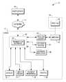
- FIG. 1is a block diagram of an example media transaction kiosk.
- FIG. 2is a front view of a user interface with an example return slot.
- FIG. 3is a rear view of the user interface.
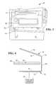
- FIG. 4is a cross-sectional view of the use interface at a dispense and return portion.
- FIG. 5is a view illustrating an example first antenna portion.
- FIG. 6is a view illustrating an example second antenna portion.
- example media transaction system 10primarily includes kiosk 12 .
- Kiosk 12dispenses digital media in storage devices 40 , which may include compact discs (CDs) and digital video discs (DVDs). Kiosk 12 may also dispense digital media in other storage devices 40 , such as Secure Digital (SD) cards, or may also electronically download digital media to customer provided storage devices.
- storage devices 40may include compact discs (CDs) and digital video discs (DVDs). Kiosk 12 may also dispense digital media in other storage devices 40 , such as Secure Digital (SD) cards, or may also electronically download digital media to customer provided storage devices.
- SDSecure Digital
- Storage devices 40may store media of various types, including, but not limited to movies, television shows, music, music videos, video game software, productivity software and a wide array of additional file types and file formats.
- Kiosk 12may include computer 20 , display 22 , input device 24 , payment peripheral 26 , printer 28 , radio frequency identification (RFID) tag reader 30 , transport system 34 , and inventor data store 36 .
- RFIDradio frequency identification
- Computer 20includes a processor, memory, program and data storage. Computer 20 may execute an operating system such as a Microsoft operating system, and a web browser for viewing web pages.
- an operating systemsuch as a Microsoft operating system
- a web browserfor viewing web pages.
- Computer 20controls operation of kiosk 12 .
- Computer 20executes transaction software 38 , which displays images of screens and records operator selections from those screens during a digital media transaction.
- a digital media transactionmay include a sale of digital media or licenses to digital media.
- Digital mediamay include, but not be limited to, movies, television shows, music, music videos, video game software, productivity software and a wide array of additional file types and file formats.
- Display 22displays the images of the transaction screens.
- Input device 24records operator selections during a digital media transaction.
- Input device 24may include a touch sensitive device or a keyboard.
- Input device 24 and display 22may be combined as a touch screen.
- Payment peripheral 26may include one or more of a card reader for reading credit, debit, and/or loyalty cards; a currency acceptor; a currency dispenser; a coin acceptor; and a coin dispenser.
- Printer 28includes a receipt printer, but may print additional information, such as coupons or other offers or promotions.
- RFID tag reader 30couples to antenna 32 , which in this example, is located in the vicinity of a digital media dispense/return slot of kiosk 12 .
- RFID tag reader 30identifies dispensed or returned digital media or both.
- Dispensed or returned storage devices 40are equipped with RFID tags 42 .
- containers of storage devices 40such as sleeves, jewel cases, or other types of cases may include RFID tags 42 .
- Delivery system 34delivers digital media to customers following selection and payment.
- delivery system 34may deliver digital media discs from storage locations within kiosk 12 or may burn digital media onto blank discs and deliver a newly burned disc.
- delivery system 34may electronically download digital media to suitable electronic storage devices, such as customer provided mobile devices. Delivery system 34 also captures and stores returned digital media to the storage locations within kiosk 12 .
- Inventory data store 36contains an inventory of digital media within kiosk 12 , either physical discs or digital media files or both.
- Transaction software 38updates the inventory of digital media each time a digital media item is dispensed or received.
- Transaction software 38may also send updated inventory information to host server 16 via network 14 .
- Host server 16may manage inventory in a plurality of kiosks 12 .
- Network 14may include a cellular communication network, a global communications network also known as the Internet, a wired or wireless network, or any combination of such networks.
- Example kiosk 12may be based upon the entertainment kiosk disclosed in commonly-assigned published U.S. application Ser. No. 10/866,387, publication number 2004/0254676, entitled “AUTOMATED BUSINESS SYSTEM AND METHOD OF VENDING AND RETURNING A CONSUMER PRODUCT”. This published application is hereby incorporated by reference.
- Example kiosk 12includes housing 50 for storing digital media. Kiosk 12 further includes user interface 52 , which includes touch screen 54 , card reader 56 , printer 58 , and dispense and retrieve slot 60 .
- Example kiosk 12may further include auxiliary display 62 for displaying movie trailers, promotions, and other information under the control of transaction software 38 .
- Dispense and retrieve slot 60includes a slot from which digital media items in cases are dispensed and into which empty cases may be inserted.
- RFID tag reader 30may be located in dispense and retrieve slot 60 or on delivery system 34 .
- the rear side of user interface 52illustrates the location of dispense and retrieve portion 70 , including antenna portions 72 and 74 .
- Antenna portion 72is mounted or located below dispense and retrieve portion 70
- antenna portion 74is mounted or located above dispense and retrieve portion 70 .
- a customerinserts protective storage case 80 into dispense and retrieve portion 70 and into slot 60 .
- RFID tag reader 30senses and reads RFID tag 42 on digital media storage device 40 .
- Transaction software 38looks up the digital media item associated with RFID tag 42 and verifies that digital media storage device 40 belongs in kiosk 12 .
- Delivery system 34transports digital media storage device 40 to a storage location with kiosk 12 .
- Transaction software 38updates inventory data 36 to reflect storage of digital media storage device 40 within kiosk 12 .
- a storage device 40 having RFID tag 42is located between antenna portions 72 and 74 and within dispense and retrieve portion 70 .
- Storage device 40may be located within a protective storage case 80 .
- the walls of dispense and retrieve portion 70should be constructed of a non-conductive, RF transparent material.
- the wallsform a recess defining a position for a customer to insert a returned storage device 40 or retrieve a dispensed storage device 40 .
- Antenna portion 72is located below bottom wall 76
- antenna portion 74is located above upper wall 78 .
- Antenna portion 74is inclined at an angle relative to antenna portion 72 , but other configurations are envisioned as user interface requirements change.
- Antenna portion 72is driven by RFID tag reader 30 to produce an electromagnetic field at an RFID frequency, such as 13.56 MHz.
- Antenna portion 74is tuned to the same frequency and passively resonates to produce another electromagnetic field, thereby supplementing the electromagnetic field produced by antenna portion 72 to cover most of the volume in front of slot 60 where RFID tag 42 is located. Coverage is provided both below and above storage device 40 and is concentrated between antenna portions 72 and 74 .
- antenna portion 74may be driven and antenna portion 72 may be passive.
- RFID tag 42receives the energy from the electromagnetic field and responds with a signal containing information identifying digital media storage device 40 .
- Transaction software 38uses the information to determine whether to accept digital media storage device 40 .
- Transaction software 38may deny acceptance if no RFID tag 42 is present or if the identification information in RFID tag 42 is not included in inventory records within inventory data store 36 .
- transaction software 38may cause delivery system 34 to either prevent insertion of digital media storage device through aperture 60 , for example, by closing or failing to open a gate, or to allow insertion by opening the gate and to transport digital media storage device 40 to an internal storage location.
- example antenna portion 72includes active loop antenna 80 , which includes two conductive loops 82 and 84 .
- active loop antenna 80includes one or more loops.
- Antenna portion 72further includes active loop tuning components 86 and coaxial connector 90 .
- Connector 90may include any suitable coaxial connector, such as a standard reverse polarity subminiature version A (RP-SMA) connector.
- the coaxial cablemay include a fifty-ohm coaxial cable between connector 90 and RFID tag reader 30 . Any transmission line suitable for 13.56 MHz RF can be used, for instance twisted pair cable and connectors.
- Example antenna portion 72may be constructed as a printed circuit board with loops 82 and 84 , active loop tuning components 86 on one side and connector 90 on an opposite side. Antenna portion 72 may be fastened with loops 82 and 84 facing bottom wall 76 of dispense and retrieve portion 70 using screws or other suitable fasteners applied through apertures 92 .
- example antenna portion 74includes passive reflective loop antenna 100 , which includes two conductive loops 102 and 104 .
- active loop antenna 80includes one or more loops.
- Antenna portion 74further includes reflective loop tuning components 106 , which may include capacitors. Reflective loop tuning components 106 may be selected or adjusted to produce resonance with active loop antenna 80 at the desired frequency of 13.56 MHz.
- Example antenna portion 74may be constructed as a printed circuit board with loops 102 and 104 and reflective loop tuning components 106 on one side. Antenna portion 74 may be fastened with loops 102 and 104 facing upper wall 78 of dispense and retrieve portion 70 using screws or other suitable fasteners applied through apertures 108 .
Landscapes
- Business, Economics & Management (AREA)
- Accounting & Taxation (AREA)
- Finance (AREA)
- General Physics & Mathematics (AREA)
- Strategic Management (AREA)
- Physics & Mathematics (AREA)
- General Business, Economics & Management (AREA)
- Engineering & Computer Science (AREA)
- Theoretical Computer Science (AREA)
- Economics (AREA)
- Marketing (AREA)
- Development Economics (AREA)
- Control Of Vending Devices And Auxiliary Devices For Vending Devices (AREA)
Abstract
Description
Claims (18)
Priority Applications (1)
| Application Number | Priority Date | Filing Date | Title |
|---|---|---|---|
| US12/960,671US8587407B2 (en) | 2010-12-06 | 2010-12-06 | Media transaction kiosk and method |
Applications Claiming Priority (1)
| Application Number | Priority Date | Filing Date | Title |
|---|---|---|---|
| US12/960,671US8587407B2 (en) | 2010-12-06 | 2010-12-06 | Media transaction kiosk and method |
Publications (2)
| Publication Number | Publication Date |
|---|---|
| US20120139705A1 US20120139705A1 (en) | 2012-06-07 |
| US8587407B2true US8587407B2 (en) | 2013-11-19 |
Family
ID=46161702
Family Applications (1)
| Application Number | Title | Priority Date | Filing Date |
|---|---|---|---|
| US12/960,671Active2031-08-26US8587407B2 (en) | 2010-12-06 | 2010-12-06 | Media transaction kiosk and method |
Country Status (1)
| Country | Link |
|---|---|
| US (1) | US8587407B2 (en) |
Cited By (2)
| Publication number | Priority date | Publication date | Assignee | Title |
|---|---|---|---|---|
| US10116151B2 (en) | 2015-09-22 | 2018-10-30 | Bseng, Llc | Battery charger rental kiosk system |
| US11630675B2 (en) | 2018-04-30 | 2023-04-18 | Hewlett-Packard Development Company, L.P. | Service kiosk device configuration |
Families Citing this family (2)
| Publication number | Priority date | Publication date | Assignee | Title |
|---|---|---|---|---|
| US8982008B2 (en)* | 2011-03-31 | 2015-03-17 | Harris Corporation | Wireless communications device including side-by-side passive loop antennas and related methods |
| US11361321B2 (en)* | 2016-04-08 | 2022-06-14 | Walmart Apollo, Llc | System and method for self-service returns |
Citations (11)
| Publication number | Priority date | Publication date | Assignee | Title |
|---|---|---|---|---|
| US6335686B1 (en) | 1998-08-14 | 2002-01-01 | 3M Innovative Properties Company | Application for a radio frequency identification system |
| US6700547B2 (en)* | 2002-04-12 | 2004-03-02 | Digital Angel Corporation | Multidirectional walkthrough antenna |
| US6707381B1 (en)* | 2001-06-26 | 2004-03-16 | Key-Trak, Inc. | Object tracking method and system with object identification and verification |
| US20040245280A1 (en)* | 2003-06-04 | 2004-12-09 | The Vendo Company | Anti-theft hopper for vending machine |
| US20050010525A1 (en)* | 2003-07-11 | 2005-01-13 | Ncr Corporation | Self-service terminal |
| US20060232382A1 (en)* | 2002-01-09 | 2006-10-19 | Bauer Donald G | Intelligent station using multiple RF antennae and inventory control system and method incorporating same |
| US20070136154A1 (en) | 2000-10-16 | 2007-06-14 | Chung Kevin K | Tracking apparatus and method, as for an exhibition |
| US20080211671A1 (en)* | 2007-01-11 | 2008-09-04 | Dagosi, Llc | Smart rfid checkout kiosk |
| US20090188983A1 (en) | 2008-01-25 | 2009-07-30 | Brian Andrew Walker | Prepaid payment device admission ticketing |
| US20100156639A1 (en)* | 2008-12-18 | 2010-06-24 | Nathaniel Christopher Herwig | Device configuration system and method |
| US20110066514A1 (en)* | 2009-09-11 | 2011-03-17 | Nintedo of America Inc. | System and/or method for handling returns involving products tied to post-paid subscriptions/services |
- 2010
- 2010-12-06USUS12/960,671patent/US8587407B2/enactiveActive
Patent Citations (11)
| Publication number | Priority date | Publication date | Assignee | Title |
|---|---|---|---|---|
| US6335686B1 (en) | 1998-08-14 | 2002-01-01 | 3M Innovative Properties Company | Application for a radio frequency identification system |
| US20070136154A1 (en) | 2000-10-16 | 2007-06-14 | Chung Kevin K | Tracking apparatus and method, as for an exhibition |
| US6707381B1 (en)* | 2001-06-26 | 2004-03-16 | Key-Trak, Inc. | Object tracking method and system with object identification and verification |
| US20060232382A1 (en)* | 2002-01-09 | 2006-10-19 | Bauer Donald G | Intelligent station using multiple RF antennae and inventory control system and method incorporating same |
| US6700547B2 (en)* | 2002-04-12 | 2004-03-02 | Digital Angel Corporation | Multidirectional walkthrough antenna |
| US20040245280A1 (en)* | 2003-06-04 | 2004-12-09 | The Vendo Company | Anti-theft hopper for vending machine |
| US20050010525A1 (en)* | 2003-07-11 | 2005-01-13 | Ncr Corporation | Self-service terminal |
| US20080211671A1 (en)* | 2007-01-11 | 2008-09-04 | Dagosi, Llc | Smart rfid checkout kiosk |
| US20090188983A1 (en) | 2008-01-25 | 2009-07-30 | Brian Andrew Walker | Prepaid payment device admission ticketing |
| US20100156639A1 (en)* | 2008-12-18 | 2010-06-24 | Nathaniel Christopher Herwig | Device configuration system and method |
| US20110066514A1 (en)* | 2009-09-11 | 2011-03-17 | Nintedo of America Inc. | System and/or method for handling returns involving products tied to post-paid subscriptions/services |
Cited By (2)
| Publication number | Priority date | Publication date | Assignee | Title |
|---|---|---|---|---|
| US10116151B2 (en) | 2015-09-22 | 2018-10-30 | Bseng, Llc | Battery charger rental kiosk system |
| US11630675B2 (en) | 2018-04-30 | 2023-04-18 | Hewlett-Packard Development Company, L.P. | Service kiosk device configuration |
Also Published As
| Publication number | Publication date |
|---|---|
| US20120139705A1 (en) | 2012-06-07 |
Similar Documents
| Publication | Publication Date | Title |
|---|---|---|
| JP5626631B2 (en) | Providing device, providing method, and providing system for delivering multimedia products | |
| US10007873B2 (en) | Multifunction smart card | |
| US9478091B2 (en) | Digital media rental and return kiosk having a three-position lockable gate mechanism and methods of operating a digital media rental and return kiosk | |
| US9519897B2 (en) | Reading apparatus and commodity sales data processing apparatus | |
| US8463432B2 (en) | Self-service media rental terminal and method of operating a self-service media rental terminal having a plurality of customer interfaces | |
| JP6182499B2 (en) | Self-checkout device and program | |
| US9489662B2 (en) | Apparatus and method for storing electronic receipts on a unified card or smartphone | |
| US10163126B2 (en) | Promotion verification method | |
| CN203084827U (en) | Intelligent interactive experience self-help vending machine | |
| US20180060834A1 (en) | Financial transaction routing | |
| Mamdapur et al. | Implementing radio frequency identification technology in libraries: Advantages and disadvantages | |
| WO2012159114A1 (en) | Customer usage statistics gathering within vending machines | |
| EP2426654A1 (en) | Commodity delivery apparatus, commodity delivery system and commodity delivery method | |
| US8587407B2 (en) | Media transaction kiosk and method | |
| US7949567B2 (en) | Integrated interface apparatus for point-of-sale system | |
| US8626339B2 (en) | Digital media transaction kiosk and method | |
| WO2003046846A1 (en) | Cashless automatic vendor system and method, and automatic vendor | |
| JP2008065799A (en) | Automatic vending machine | |
| JP4793139B2 (en) | vending machine | |
| JP4743025B2 (en) | vending machine | |
| US9251390B2 (en) | Item identification device antenna | |
| WO2006031202A1 (en) | Promotional coupon distribution | |
| US8498735B2 (en) | Storage method for digital media items | |
| RU85013U1 (en) | TRANSACTION AUTOMATIC DEVICE FOR ISSUING DIGITAL INFORMATION FILES | |
| JP2010140406A (en) | Vending machine |
Legal Events
| Date | Code | Title | Description |
|---|---|---|---|
| AS | Assignment | Owner name:NCR CORPORATION, GEORGIA Free format text:ASSIGNMENT OF ASSIGNORS INTEREST;ASSIGNOR:CLAESSEN, ALBERT;REEL/FRAME:025450/0780 Effective date:20101202 | |
| STCF | Information on status: patent grant | Free format text:PATENTED CASE | |
| AS | Assignment | Owner name:JPMORGAN CHASE BANK, N.A., AS ADMINISTRATIVE AGENT, ILLINOIS Free format text:SECURITY AGREEMENT;ASSIGNORS:NCR CORPORATION;NCR INTERNATIONAL, INC.;REEL/FRAME:032034/0010 Effective date:20140106 Owner name:JPMORGAN CHASE BANK, N.A., AS ADMINISTRATIVE AGENT Free format text:SECURITY AGREEMENT;ASSIGNORS:NCR CORPORATION;NCR INTERNATIONAL, INC.;REEL/FRAME:032034/0010 Effective date:20140106 | |
| AS | Assignment | Owner name:JPMORGAN CHASE BANK, N.A., ILLINOIS Free format text:SECURITY AGREEMENT;ASSIGNORS:NCR CORPORATION;NCR INTERNATIONAL, INC.;REEL/FRAME:038646/0001 Effective date:20160331 | |
| FPAY | Fee payment | Year of fee payment:4 | |
| MAFP | Maintenance fee payment | Free format text:PAYMENT OF MAINTENANCE FEE, 8TH YEAR, LARGE ENTITY (ORIGINAL EVENT CODE: M1552); ENTITY STATUS OF PATENT OWNER: LARGE ENTITY Year of fee payment:8 | |
| AS | Assignment | Owner name:NCR VOYIX CORPORATION, GEORGIA Free format text:RELEASE OF PATENT SECURITY INTEREST;ASSIGNOR:JPMORGAN CHASE BANK, N.A., AS ADMINISTRATIVE AGENT;REEL/FRAME:065346/0531 Effective date:20231016 Owner name:BANK OF AMERICA, N.A., AS ADMINISTRATIVE AGENT, NORTH CAROLINA Free format text:SECURITY INTEREST;ASSIGNOR:NCR VOYIX CORPORATION;REEL/FRAME:065346/0168 Effective date:20231016 | |
| AS | Assignment | Owner name:NCR VOYIX CORPORATION, GEORGIA Free format text:CHANGE OF NAME;ASSIGNOR:NCR CORPORATION;REEL/FRAME:065820/0704 Effective date:20231013 | |
| MAFP | Maintenance fee payment | Free format text:PAYMENT OF MAINTENANCE FEE, 12TH YEAR, LARGE ENTITY (ORIGINAL EVENT CODE: M1553); ENTITY STATUS OF PATENT OWNER: LARGE ENTITY Year of fee payment:12 |