US8587356B2 - Recoverable and reconfigurable pipeline structure for state-retention power gating - Google Patents
Recoverable and reconfigurable pipeline structure for state-retention power gatingDownload PDFInfo
- Publication number
- US8587356B2 US8587356B2US13/403,597US201213403597AUS8587356B2US 8587356 B2US8587356 B2US 8587356B2US 201213403597 AUS201213403597 AUS 201213403597AUS 8587356 B2US8587356 B2US 8587356B2
- Authority
- US
- United States
- Prior art keywords
- storage element
- electronic circuit
- state
- logic stage
- operation mode
- Prior art date
- Legal status (The legal status is an assumption and is not a legal conclusion. Google has not performed a legal analysis and makes no representation as to the accuracy of the status listed.)
- Active
Links
Images


Classifications
- H—ELECTRICITY
- H03—ELECTRONIC CIRCUITRY
- H03K—PULSE TECHNIQUE
- H03K3/00—Circuits for generating electric pulses; Monostable, bistable or multistable circuits
- H03K3/02—Generators characterised by the type of circuit or by the means used for producing pulses
- H03K3/353—Generators characterised by the type of circuit or by the means used for producing pulses by the use, as active elements, of field-effect transistors with internal or external positive feedback
- H03K3/356—Bistable circuits
- H03K3/356017—Bistable circuits using additional transistors in the input circuit
- H03K3/356052—Bistable circuits using additional transistors in the input circuit using pass gates
- H03K3/35606—Bistable circuits using additional transistors in the input circuit using pass gates with synchronous operation
- H—ELECTRICITY
- H03—ELECTRONIC CIRCUITRY
- H03K—PULSE TECHNIQUE
- H03K3/00—Circuits for generating electric pulses; Monostable, bistable or multistable circuits
- H03K3/02—Generators characterised by the type of circuit or by the means used for producing pulses
- H03K3/353—Generators characterised by the type of circuit or by the means used for producing pulses by the use, as active elements, of field-effect transistors with internal or external positive feedback
- H03K3/356—Bistable circuits
- H03K3/356008—Bistable circuits ensuring a predetermined initial state when the supply voltage has been applied; storing the actual state when the supply voltage fails
Definitions
- This disclosurerelates generally to the design, implementation and utilization of electronic circuits, and more specifically, to a recoverable and reconfigurable pipeline structure for use in electronic circuits.
- Electronic circuitse.g., integrated circuits (ICs), microprocessors, microcontrollers, digital signal processors, digital signal controllers, sensors, RF power ICs, power management ICs, system on a chip (SoC) devices, and the like
- ICsintegrated circuits
- SoCsystem on a chip
- Leakage currentcan include reverse-biased junction leakage current, gate-induced drain leakage, gate direct-tunneling leakage and subthreshold or “weak inversion” leakage.
- Local, state-retention storage element state storageis typically simpler and faster to implement but consumes more die area, increases leakage power dissipation, negatively impacts electronic circuit performance, and increases design complexity in order to routing the separate power supply rails typically required by such storage elements, counteracting many of the benefits derived from techniques such as power gating.
- FIG. 1illustrates an electronic circuit including a number of logic stages interleaved with state-retention flip flops to facilitate power gating according to the prior art. More specifically, the electronic circuit 100 of FIG. 1 includes a number, “n” of logic stages 102 - 106 , where each logic stage is separated from adjacent logic stages via state-retention flip flops 108 a - 108 n as shown.
- Each state-retention flip flop 108includes inputs for data (labeled “D”), normal operation mode and a low-power operation mode power supply rail voltages or “supply voltages” (Vdd and Vddc, where Vddc is a voltage lower than Vdd and Vddc is constantly applied to each of state-retention flip flops 108 ), a clock signal and a state-retention enable control signal as well as a data output (labeled “Q”).
- Electronic circuit 100 of FIG. 1further includes a memory 112 for storage of an evaluation result of electronic circuit 100 or remote storage for system state of electronic circuit 100 as previously described.
- FIG. 1illustrates an electronic circuit including a number of logic stages interleaved with state-retention flip flops to facilitate power gating according to the prior art
- FIG. 2illustrates an electronic circuit according to a first embodiment of the inventive subject matter
- FIG. 3illustrates a timing diagram representation of one or more signals associated with the electronic circuit of FIG. 2 ;
- FIG. 4illustrates a two-clock-signal-based flow-through storage element useable with one or more embodiments of the inventive subject matter
- FIG. 5illustrates a timing diagram representation of one or more signals associated with the storage element of FIG. 4 ;
- FIG. 6illustrates a single-clock-signal-based flow-through storage element useable with one or more embodiments of the inventive subject matter
- FIG. 7illustrates a timing diagram representation of one or more signals associated with the storage element of FIG. 6 ;
- FIG. 8illustrates an electronic circuit according to a second embodiment of the inventive subject matter
- FIG. 9illustrates a timing diagram representation of one or more signals associated with the electronic circuit of FIG. 8 ;
- FIG. 10illustrates an electronic circuit according to a third embodiment of the inventive subject matter
- FIG. 11illustrates a timing diagram representation of one or more signals associated a test mode of the electronic circuit of FIG. 10 ;
- FIG. 12illustrates a timing diagram representation of one or more signals associated another test mode of the electronic circuit of FIG. 10 ;
- FIG. 13illustrates an electronic circuit reconfiguration register according to one or more embodiments of the inventive subject matter.
- FIG. 14illustrates a high-level process flow diagram representing an electronic circuit reconfiguration process according to one or more embodiments of the inventive subject matter.
- a logic pipelineis configured in a first operation mode where all of its sequential storage elements contain a first set of states of the pipeline operating in an initial state of Power Gating (PG).
- the logic pipelineis reconfigurable in real-time to a second operation mode where only a portion of the sequential storage elements coupled to a set of starting points and ending points along the logic pipeline contain valid set of states, whereas the remaining sequential storage elements do not retain valid sets of states upon entering a second state of power gating (PG).
- the described logic pipelinecan be configured in real-time to a third operation mode where the remaining sequential storage elements recover the first set of states from the portion of sequential storage elements at starting and ending points along the logic pipeline, upon entering a third state of PG.
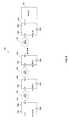
- FIG. 2illustrates an electronic circuit according to a first embodiment of the inventive subject matter.
- Such an electronic circuitmay comprise, in various embodiments, a circuit, logic component, or any subcomponent thereof.
- an electronic circuit as described hereincomprises a portion of a KinetisTM microcontroller or QorIQ® processor, both provided by Freescale Semiconductor, Inc. of Austin, Tex.
- Electronic circuit 200 of the depicted embodimentincludes state-retention storage elements 208 (e.g., state-retention flip flop 108 as described with respect to FIG. 1 ) coupled to a logic array which includes a number of logic stages 202 and a number of additional storage elements 210 as shown.
- state-retention storage elements 208e.g., state-retention flip flop 108 as described with respect to FIG. 1
- a memory 212is also included as part of electronic circuit 200 .
- a memorymay be excluded or may be provided separately from electronic circuit 200 .
- electronic circuit 200may operate in any of a plurality of power gating modes as will now be describe in greater detail in conjunction with a description of FIG. 3 which illustrates a timing diagram representation of one or more signals associated with the electronic circuit of FIG. 2 .
- a rail voltage (Vdd) as well as a secondary, lower rail voltage Vddc and a clock signalare applied to each of state-retention storage elements 208 and storage elements 210 and the state of electronic circuit 200 (i.e., the output of each of logic stages 202 - 206 ) is retained in state-retention storage elements 208 and storage elements 210 .
- Vddrail voltage
- Vddcsecondary, lower rail voltage
- a clock signalare applied to each of state-retention storage elements 208 and storage elements 210 and the state of electronic circuit 200 (i.e., the output of each of logic stages 202 - 206 ) is retained in state-retention storage elements 208 and storage elements 210 .
- electronic circuits and their associated devicesoperate at full power in a normal operational or execution mode.
- logic stages 202 - 206may represent a datapath or instruction execution pipeline of, for example, a microcontroller or SoC.
- a state-retention enable control signal(sr_en) is provided such that state-retention storage elements 208 are configured to retain state utilizing rail voltage Vdd rather than Vddc as associated with a low-power or “sleep” power gating operational mode which will be discussed further herein.
- the sr_en control signalis held at a logical “low” value during this time period.
- a pipeline flow-through control (PFL) control signalis maintained (at a logical “low” value) such that storage elements 210 retain (e.g., latch or store) the outputs of their adjacent logic stages rather than operating transparently to merely pass or “flow-through” such outputs to the next adjacent pipeline or logic stage.
- PFLpipeline flow-through control
- FIG. 2further illustrates a block diagram of a pipeline 250 of an electronic device in accordance with an alternative embodiment of the present disclosure.
- pipeline 250is an instruction pipeline of a data processor.
- Pipeline 250includes state retention flip-flops 270 and 275 , pipeline stages 272 , 273 , and 274 , and flushable flip-flops 280 and 281 .
- “Flow-through” flushable flip-flops 280 and 281are each configured similarly to storage elements 210 .
- State retention flip-flop 270includes an input to receive data, an output, and a clock input to receive the clock signal CP.
- Pipeline stage 272includes a connection to an output of state retention flip-flop 270 , a connection to receive clock signal CP, and an output.
- a D input of flushable flip-flop 280is connected to an output of pipeline stage 272 , a FL input is connected to receive the flush control signal FLUSH, and a CK input is connected to receive the clock signal CP.
- Pipeline stage 273includes a connection to a Q output of flushable flip-flop 280 , a connection to receive the clock signal CP, and an output.
- a D input of flushable flip-flop 281is connected to an output of pipeline stage 273 , a FL input is connected to receive the flush control signal FLUSH, and a CK input is connected to receive the clock signal CP.
- Pipeline stage 274includes a connection to a Q output of flushable flip-flop 281 , a connection to receive the clock signal CP, and an output.
- State retention flip-flop 275includes a data input connected to an output of pipeline stage 274 , a data output, and a clock input to receive the clock signal CP.
- State-retention flip-flops 270 and 275are each configured to latch data at their inputs based on edges of the clock signal CP. In addition, state-retention flip-flops 270 and 275 are each configured to retain their latched data when pipeline 250 is placed in a low-power mode.
- Pipeline stages 272 - 274are each configured to perform different operations to allow pipeline 250 to execute its designated functions. For example, in an embodiment each of pipeline stages 272 - 274 performs different operations for an instruction pipeline. Thus, pipeline stage 272 can be configured to dispatch instructions while pipeline stage 273 is configured to execute dispatched instructions. During operation, pipeline stages 272 - 274 receive data from and provide data to the flip-flops connected to the corresponding stage. Thus, for example, pipeline stage 272 can receive input data from state-retention flip-flop 270 and provide output data to flushable flip-flop 280 .
- the flush control signal FLUSHcan be used to control whether flushable flip-flops 280 and 281 are placed in the normal mode or the buffer mode.
- flushable flip-flops 280 and 281are placed in the normal mode when pipeline 250 is in a normal, active power mode and are placed in the buffering mode when pipeline 250 is undergoing a power gating sequence to allow pipeline 250 to exit the low-power mode efficiently.
- the clock signal CPcan enter an indeterminate state.
- flushable flip-flops 280 and 281can be placed in the buffering mode during testing of pipeline 250 , thereby simplifying the test process. For example, by placing flushable flip-flops 280 and 281 in the buffering mode, the scan chain for testing of the pipeline can be reduced, thereby reducing the complexity of the test process.
- flushable flip-flops 280 and 281can be configured such that each of the flip-flops includes a master stage and slave stage that can individually be placed in the normal or buffering modes. Accordingly, during testing of pipeline 250 , flip-flop 280 can be configured so that its master stage is placed in the normal mode and its slave stage is placed in the buffering mode. Flip-flop 280 is thus effectively configured as a transparent L 1 latch (a latch that is controlled by rising edges of the clock signal CP). Further, flip-flop 281 can be configured so that its master stage is placed in the buffering mode and its slave stage is placed in the normal mode. Flip-flop 281 is thus effectively configured as a transparent L 2 latch (a latch that is controlled by the falling edge of the clock signal CP). This configuration can allow for the timing and operation of the stages of pipeline 250 to be tested in different ways, thus providing for testing flexibility.
- independent flush control signalscan be provided to each of the flushable flip-flops in the pipeline, so that each flip-flop can be independently placed in the normal mode or the buffer mode.
- the state of each flush control signalcan be set based on a value stored at a reprogrammable register, so that the mode of each flushable flip-flop can be reprogrammed by a user.
- the flush control signalscan independently set the operating modes for each master and slave stage of the flushable-flip flops. Thus, the user can independently set the operating mode for each stage of each flushable flip-flop by storing a value at the reprogrammable register.
- a next power gating operational moderepresented within the context of FIG. 3 as time period T 2 , although Vddc is continuously applied to state-retention storage elements 208 , rail voltage Vdd is withdrawn from all of the elements of electronic circuit 200 , an applied clock signal may also be withdrawn, held at a logical “low” level or vary/be undetermined.
- an associated electronic circuitis being “powered down” to enter, during or at the conclusion of the mode, a “low power” operational state.
- the sr_en control signalis asserted/held at a logical “high” level so that state information may be retained by state-retention storage elements 208 using the lower power Vddc rail voltage.
- the sr_en control signal, clock signal, and PFL control signalare all held at a logical “high” level in order to flush erroneous logic stage output and protect memory (e.g., memory 212 ) as the previously retained electronic circuit state is propagated from an associated state-retention storage element 208 through all prior logic stages as the Vdd rail voltage is reapplied as shown.
- the associated power gating operational modeentails a “recovery” or return to a normal operational mode for associated electronic circuits and devices subsequently, during a time period represented as T 4 , when electronic circuit 200 returns to its normal operational mode.
- the Vdd rail voltageis applied to all functional elements of electronic circuit 200 , the sr_en control signal is de-asserted as is the PFL controls signal once all of storage elements 210 have been flushed and the clock signal is re-applied to the circuit as normal operations and logic evaluation is resumed.
- FIG. 4illustrates a two-clock-signal-based flow-through storage element useable with one or more embodiments of the inventive subject matter. More specifically, in the embodiment of FIG. 4 , one or more of storage elements 210 of FIG. 2 is implemented using a level-sensitive scan design (LSSD) “master-slave” design for test or “scan” flip flop (MSFF). Such LSSD MSFF elements are frequently provided as part of a standard logic or “cell” library for use in application specific integrated circuit (ASIC) and field-programmable gate array (FPGA) design. Since the use of storage elements 210 within electronic circuit 200 is prevalent, the use of an existing “IP-core” library element, avoids changes to existing, established tooling. Use of a two-clock signal based flow-through storage element eliminates the need to provide separate explicit logic to generate a PFL control signal.
- LSSDlevel-sensitive scan design
- MSFFmaster-slave
- ASICapplication specific integrated circuit
- FPGAfield-programmable gate array
- the flow-through storage element design depicted in FIG. 4requires the application of two separate clock signals, C 1 and C 2 as shown and that each of the supplied clocks is buffered.
- MSFF 400operates in a conventional manner to retain supplied state information in one power gating operation mode and may be reconfigured to act as a flow-through buffer for a data input “D” by removing a feedback path inverter from each of the component latches of the device via the application of clock signals C 1 and C 2 and their buffered counterpart clock signals C 1 b and C 2 b respectively as shown.
- the illustrated MSFF 400includes an N-channel type insulated gate field effect transistor (IGFET) such as an N-type Metal-Oxide-Semiconductor Field Effect Transistor (MOSFET) or “NMOS” 402 coupled to the data input signal “D” with clock signal C 1 applied to the device's gate.
- IGFETN-channel type insulated gate field effect transistor
- MOSFETMetal-Oxide-Semiconductor Field Effect Transistor
- NMOS 402coupled to the data input signal “D” with clock signal C 1 applied to the device's gate.
- the output of NMOS 402is in turn coupled to a latch composed of inverters 404 and 406 arranged in a feedback path as shown.
- a clock signal C 1 and a buffer-delayed copy C 1 bare applied to feedback inverter 406 to render the feedback path open and to reduce dynamic power dissipation.
- MSFF 400further includes an additional N-channel type IGFET, NMOS 408 which passes the output of the previously-described first latch to a second latch composed of inverters 410 and 412 arranged in a similar feedback path as well as to an output of MSFF 400 via an inverter 414 .
- NMOS 408which passes the output of the previously-described first latch to a second latch composed of inverters 410 and 412 arranged in a similar feedback path as well as to an output of MSFF 400 via an inverter 414 .
- FIG. 5illustrates a timing diagram representation of one or more signals associated with the storage element of FIG. 4 .
- a first power gating operational moderepresented within the context of FIG. 5 as time period T 1 , during which a rail voltage (Vdd) as well as a secondary, lower rail voltage Vddc and a clock signal are applied to each of state-retention storage elements and storage elements as previously-described, clock signals C 1 and C 2 are active at a predetermined frequency.
- Vddrail voltage
- Vddcsecondary, lower rail voltage
- clock signals C 1 and C 2are active at a predetermined frequency.
- T 2the Vdd rail voltage is withdrawn from the associated electronic circuit and clocks C 1 and C 2 may be low or undetermined.
- a third power gating operational moderepresented within the context of FIG.
- MSFF 400is flushed by holding both C 1 and C 2 clock signals at a logical “high” value such that the feedback/latch paths created by inverters 406 and 412 are both cut off such that any applied input data signal is passed through NMOS transistors 402 and 408 and inverters 404 and 414 to the output of MSFF 400 .
- a fourth power gating operational moderepresented within the context of FIG. 5 as time period T 4 , MSFF 400 and associated clock signals C 1 and C 2 returns to normal operation/processing.
- FIG. 6illustrates a single-clock-signal-based flow-through storage element useable with one or more embodiments of the inventive subject matter.
- MSFF 600 of FIG. 6includes NMOS transistors 602 (coupled to a data input signal “D”) and 608 and master and slave latches including inverters 604 and 606 and 610 and 612 , respectively and an output coupled to an inverter 614 from a “slave” latch as shown.
- MSFF 600however utilizes a “mux/multiplexer-D” design for test/scan-based design approach however which is not level-sensitive but rather utilizes a separate multiplexer (not shown) to select between a primary data input signal and a secondary data input signal (e.g., a test or scan chain input).
- MSFF 600therefore further includes clock signal control circuitry 616 which in turn includes an inverter 618 coupled to an input clock signal, a transmission gate 620 , and a P-channel type insulated gate field effect transistor (IGFET) such as an P-type Metal-Oxide-Semiconductor Field Effect Transistor (MOSFET) or “PMOS” 622 .
- IGFETP-channel type insulated gate field effect transistor
- MSFF 600An embodiment of the present inventive subject matter utilizing MSFF 600 or one having similar characteristics reduces the number of transistors required for implementation as well as setup and hold time, clock loading, and logic (D ⁇ Q) delay. Moreover, in alternative embodiments, MSFFs such as MSFF 600 may be dynamically reconfigured into a buffer during a recovery power gating operational mode or during a functional/scan test operational mode, resulting in a reduction in the number of required scan chains and accordingly in test times.
- FIG. 7illustrates a timing diagram representation of one or more signals associated with the storage element of FIG. 6 .
- a first power gating operational moderepresented within the context of FIG. 7 as time period T 1 , during which a rail voltage (Vdd) as well as a secondary, lower rail voltage Vddc and a clock signal (CLK) are applied to each of state-retention storage elements and storage elements as previously-described, a PFL control signal is held at a logical “low” level as shown.
- a second power gating operational moderepresented within the context of FIG. 7 as time period T 2 , the Vdd rail voltage is withdrawn from the associated electronic circuit and clock signal CLK may be low or undetermined.
- a third power gating operational moderepresented within the context of FIG. 7 as time period T 3
- MSFF 600is flushed by raising the PFL control signal to a logical “high” value such that both clock signal CLK and a buffered clock signal CLKb applied to NMOS 602 are similarly held to a logical “high” level such that any applied input data signal is passed through NMOS transistors 602 and 608 and inverters 604 and 614 to the output of MSFF 600 .
- a fourth power gating operational moderepresented within the context of FIG. 7 as time period T 4
- MSFF 600resumes normal operation/processing and, after a sufficient time period elapsed to ensure MSFF 600 has been flushed, the PFL control signal is brought to a logical “low” level.
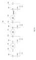
- FIG. 8illustrates an electronic circuit according to a second embodiment of the inventive subject matter. More specifically, electronic circuit 800 provides sequential logic stage or pipeline flush control via a plurality of separate PFL control signals as will be described in greater detail herein. Similarly to that previously described with respect to FIG. 2 , electronic circuit 800 of the depicted embodiment includes state-retention storage elements 808 coupled to a logic array which includes a number of logic stages 802 and a number of additional storage elements 810 , which, in the illustrated embodiment is further coupled to a memory 812 , as shown. In operation, electronic circuit 800 may operate in any of a plurality of power gating modes as described herein. Unlike the electronic circuit depicted and described with regard to FIG.
- each of additional storage elements 810has an independently controllable/assertable PFL control signal allowing such storage elements to be sequentially or otherwise independently flushed.
- sequential rather than simultaneous flushing/bypass/flow-throughreduces peak inrush current, I*R drop, and di/dt noise during a recovery power gating operational mode.
- such a sequential flush recovery methodis utilized between state-retention storage element-bounded stages.
- a time period during which each storage element is bypassed/flushedis programmable.
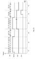
- FIG. 9illustrates a timing diagram representation of one or more signals associated with the electronic circuit of FIG. 8 .
- a first power gating operational moderepresented within the context of FIG. 9 as time period T 1 , during which a rail voltage (Vdd) as well as a secondary, lower rail voltage Vddc (not shown) and a clock signal (CLK) are applied to each of state-retention storage elements and storage elements as previously-described, a plurality of PFL control signals are held at a logical “low” level as shown.
- Vddrail voltage
- Vddcsecondary, lower rail voltage
- CLKclock signal
- FIG. 10illustrates an electronic circuit according to a third embodiment of the inventive subject matter. More specifically, electronic circuit 1000 provides pipeline or logic stage merge functionality utilizing one or more storage elements such as have been described herein with respect to, for example, FIGS. 5 and 7 . By merging logic or pipeline stages a built in self test (BIST) testing mode is provided. Each storage element 1010 of the depicted electronic circuit includes a separate PFL control signal input as will be described in greater detail herein. Storage elements 1010 are interspersed between logic stages 1002 - 1006 as shown. According to one embodiment, logic stage 1002 includes address pre-decode error correcting code (ECC) coding, logic stage 1004 includes static random access memory (SRAM) access functionality, and logic stage 1006 provides ECC functionality.
- ECCaddress pre-decode error correcting code
- SRAMstatic random access memory
- testing modesinclude a memory BIST mode with optional ECC to leverage ECC error correction for yield loss recover on soft-error failures.
- FIG. 11illustrates a timing diagram representation of one or more signals associated a first test mode of the electronic circuit of FIG. 10 .
- a clock signal CLK having a first frequencyis applied to all storage elements 1010 of electronic circuit 1000 , PFL control signals PFL 1 and PFL 2 are held at a logical “low” level.
- a conventional BIST testing modeis entered and a set of input test vectors generated by the BIST testing mode (BIST engine) is applied to an input of a circuit under test, i.e., electronic circuit 1000 .
- a PFL 1 control signalis set to a logical “high” value, effectively merging logic stage 1002 and logic stage 1004 into a single logic or pipeline stage for test and a frequency of the applied clock signal CLK is decreased to allow input propagation and processing via the merged logic stage.
- a PFL 2 control signalis set to a logical “high” value merging logic stage 1006 with the previously-merged logic stage generated during time period T 3 .
- the frequency of the applied clock signal CLKis reduced to enable propagation and processing of applied data inputs to the generated merged logic stage comprising logic stages 1002 - 1006 .
- the input clock signal CLKis returned to its original frequency and a function operation mode is resumed.
- the applied clock signal cycle timeis defined as being greater than or equal to the sum of logic propagation delay, setup time of data to clock/retain at an associated storage element, and clock to data launch time of the associated storage element.
- FIG. 12illustrates a timing diagram representation of one or more signals associated with a second test mode of the electronic circuit of FIG. 10 . More specifically, a setup and delay testing mode is provided in the depicted embodiment whereby by selectively merging logic stages and therefore bypassing associated storage elements, timing characteristics such as launch and hold time of bypassed storage elements may be determined.
- a scan_en control signalis asserted and deasserted to launch and capture scan chain data inputs to portions of electronic circuit 1000 .
- the described scan_en control signalis held to a logical “high” level to load scan chain values into storage elements 1010 of electronic circuit 1000 .
- scan chain valuesmay be loaded via a mux/multiplexer-D type scan input port of storage elements 1010 (not shown in FIG. 10 ).
- the scan_en control signalis brought to a logical “low” value to launch the scan chain and capture results using a conventional scan testing technique.
- a timing edge of a PFL 1 control signalmay be varied (as represented by PFL 1 ′) to bypass an associated storage element 1010 b and to merge adjacent logic stages 1002 and 1004 .
- Whether storage element 1010 b captures inputs provided by a prior logic stage 1002will depend on the delay characteristics (e.g., setup and hold time) of the storage element and when PFL 1 is clocked. Consequently, setup and delay timing margins for each of storage elements 1010 may be determined using the indicated technique.
- delay characteristicse.g., setup and hold time
- FIG. 13illustrates an electronic circuit reconfiguration register according to one or more embodiments of the inventive subject matter.
- the indicated reconfiguration register of FIG. 13includes a reset input and a program input for populating one or more fields or storage elements 1302 - 1308 of the reconfiguration register as shown. More specifically, the reconfiguration register of FIG. 13 includes a power gating module identifier 1302 , a power gating state identifier 1304 , a power gating mode bit 1306 and a logic test mode bit 1308 .
- an array of logic stages or pipelinemay be reconfigured or analyzed in keeping with the embodiments described herein.
- FIG. 14illustrates a high-level process flow diagram representing an electronic circuit reconfiguration process according to one or more embodiments of the inventive subject matter.
- a systeme.g., an electronic circuit
- a systeminitially enters a “sleep” power gating mode (process block 1402 ) wherein a power supply voltage is gated off from a supply voltage input of the electronic circuit.
- a determinationis made whether a power gating state indicator holds a “11” value indicating that a sleep power gating mode is the next power gating mode to be entered by the system. If so, the depicted process returns to process block 1402 as shown.
- a PFL modeis enabled (process block 1406 ) where select storage elements are reconfigured to act as buffers or otherwise to bypass or “flow-through” received inputs.
- a power supply voltage (Vdd)is then ramped up at an associated input to the electronic circuit (process block 1408 ).
- Vddpower supply voltage
- a test modeis entered whereby the system's recovery operation may be debugged (process block 1412 ).
- a “sleep” power gating mode(process block 1402 ) is associated with a power gating operational mode such as that represented within the context of FIG. 3 as time period T 2 .
- PFL mode(process block 1406 ) corresponds to a power gating operational mode such as that represented within the context of FIG. 3 as time period T 3
- active or functional operational mode(process block 1414 ) corresponds to power gating operational modes represented by both time period T 1 and T 4 of FIG. 3 .
- an active or functional state in which logic is activated(process block 1414 ) may be retained for an extended period of time without entering directly into a sleep or PFL mode as shown.
Landscapes
- Semiconductor Integrated Circuits (AREA)
Abstract
Description
Claims (19)
Priority Applications (1)
| Application Number | Priority Date | Filing Date | Title |
|---|---|---|---|
| US13/403,597US8587356B2 (en) | 2011-12-15 | 2012-02-23 | Recoverable and reconfigurable pipeline structure for state-retention power gating |
Applications Claiming Priority (2)
| Application Number | Priority Date | Filing Date | Title |
|---|---|---|---|
| US13/326,685US8941427B2 (en) | 2011-12-15 | 2011-12-15 | Configurable flip-flop |
| US13/403,597US8587356B2 (en) | 2011-12-15 | 2012-02-23 | Recoverable and reconfigurable pipeline structure for state-retention power gating |
Related Parent Applications (1)
| Application Number | Title | Priority Date | Filing Date |
|---|---|---|---|
| US13/326,685Continuation-In-PartUS8941427B2 (en) | 2011-12-15 | 2011-12-15 | Configurable flip-flop |
Publications (2)
| Publication Number | Publication Date |
|---|---|
| US20130154707A1 US20130154707A1 (en) | 2013-06-20 |
| US8587356B2true US8587356B2 (en) | 2013-11-19 |
Family
ID=48609517
Family Applications (1)
| Application Number | Title | Priority Date | Filing Date |
|---|---|---|---|
| US13/403,597ActiveUS8587356B2 (en) | 2011-12-15 | 2012-02-23 | Recoverable and reconfigurable pipeline structure for state-retention power gating |
Country Status (1)
| Country | Link |
|---|---|
| US (1) | US8587356B2 (en) |
Cited By (2)
| Publication number | Priority date | Publication date | Assignee | Title |
|---|---|---|---|---|
| US9503086B1 (en)* | 2015-09-16 | 2016-11-22 | Apple Inc. | Lockup latch for subthreshold operation |
| US9548735B1 (en)* | 2012-12-19 | 2017-01-17 | Maxim Intergrated Products, Inc. | System and method for adaptive power management |
Families Citing this family (3)
| Publication number | Priority date | Publication date | Assignee | Title |
|---|---|---|---|---|
| KR101925566B1 (en)* | 2012-06-13 | 2018-12-05 | 삼성전자주식회사 | I/O data retention device |
| CN115276613A (en)* | 2022-08-05 | 2022-11-01 | 珠海錾芯半导体有限公司 | An integrated circuit based on edge flip-flop and sensitive latch and its programmable circuit |
| US20250110538A1 (en)* | 2023-09-28 | 2025-04-03 | Advanced Micro Devices, Inc. | Granular power gating override |
Citations (17)
| Publication number | Priority date | Publication date | Assignee | Title |
|---|---|---|---|---|
| US5889788A (en) | 1997-02-03 | 1999-03-30 | Motorola, Inc. | Wrapper cell architecture for path delay testing of embedded core microprocessors and method of operation |
| US5920575A (en) | 1997-09-19 | 1999-07-06 | International Business Machines Corporation | VLSI test circuit apparatus and method |
| US20020075058A1 (en)* | 2000-12-19 | 2002-06-20 | Chi-Yi Hwang | Apparatus for low-power, high performance, and cycle accurate test simulation |
| US20030226000A1 (en) | 2002-05-30 | 2003-12-04 | Mike Rhoades | Collapsible pipeline structure and method used in a microprocessor |
| US20060192596A1 (en) | 2005-02-25 | 2006-08-31 | Ravindraraj Ramaraju | Integrated circuit having a low power mode and method therefor |
| US20060192604A1 (en) | 2005-02-25 | 2006-08-31 | Ravindraraj Ramaraju | Integrated circuit storage element having low power data retention and method therefor |
| US7155618B2 (en) | 2002-03-08 | 2006-12-26 | Freescale Semiconductor, Inc. | Low power system and method for a data processing system |
| US20070222480A1 (en) | 2006-03-24 | 2007-09-27 | Freescale Semiconductor, Inc. | Circuit and method for latch bypass |
| US20080086626A1 (en)* | 2006-10-05 | 2008-04-10 | Simon Jones | Inter-processor communication method |
| US20080250271A1 (en)* | 2007-04-03 | 2008-10-09 | Arm Limited | Error recovery following speculative execution with an instruction processing pipeline |
| US7453756B2 (en) | 2006-08-31 | 2008-11-18 | Freescale Semiconductor, Inc. | Method for powering an electronic device and circuit |
| US7548103B2 (en) | 2006-10-26 | 2009-06-16 | Freescale Semiconductor, Inc. | Storage device having low power mode and methods thereof |
| US7548102B2 (en) | 2006-07-14 | 2009-06-16 | Freescale Semiconductor, Inc. | Data latch with minimal setup time and launch delay |
| US20090213668A1 (en) | 2008-02-21 | 2009-08-27 | Shayan Zhang | Adjustable pipeline in a memory circuit |
| US20090256608A1 (en) | 2008-04-10 | 2009-10-15 | Broadcom Corporation | Low leakage data retention flip flop |
| US7710177B2 (en)* | 2007-09-12 | 2010-05-04 | Freescale Semiconductor, Inc. | Latch device having low-power data retention |
| US7843218B1 (en) | 2009-10-28 | 2010-11-30 | Freescale Semiconductor, Inc. | Data latch with structural hold |
- 2012
- 2012-02-23USUS13/403,597patent/US8587356B2/enactiveActive
Patent Citations (19)
| Publication number | Priority date | Publication date | Assignee | Title |
|---|---|---|---|---|
| US5889788A (en) | 1997-02-03 | 1999-03-30 | Motorola, Inc. | Wrapper cell architecture for path delay testing of embedded core microprocessors and method of operation |
| US5920575A (en) | 1997-09-19 | 1999-07-06 | International Business Machines Corporation | VLSI test circuit apparatus and method |
| US20020075058A1 (en)* | 2000-12-19 | 2002-06-20 | Chi-Yi Hwang | Apparatus for low-power, high performance, and cycle accurate test simulation |
| US7155618B2 (en) | 2002-03-08 | 2006-12-26 | Freescale Semiconductor, Inc. | Low power system and method for a data processing system |
| US20030226000A1 (en) | 2002-05-30 | 2003-12-04 | Mike Rhoades | Collapsible pipeline structure and method used in a microprocessor |
| US20060192596A1 (en) | 2005-02-25 | 2006-08-31 | Ravindraraj Ramaraju | Integrated circuit having a low power mode and method therefor |
| US20060192604A1 (en) | 2005-02-25 | 2006-08-31 | Ravindraraj Ramaraju | Integrated circuit storage element having low power data retention and method therefor |
| US20070222480A1 (en) | 2006-03-24 | 2007-09-27 | Freescale Semiconductor, Inc. | Circuit and method for latch bypass |
| US7362134B2 (en) | 2006-03-24 | 2008-04-22 | Freescale Semiconductor, Inc. | Circuit and method for latch bypass |
| US7548102B2 (en) | 2006-07-14 | 2009-06-16 | Freescale Semiconductor, Inc. | Data latch with minimal setup time and launch delay |
| US7453756B2 (en) | 2006-08-31 | 2008-11-18 | Freescale Semiconductor, Inc. | Method for powering an electronic device and circuit |
| US20080086626A1 (en)* | 2006-10-05 | 2008-04-10 | Simon Jones | Inter-processor communication method |
| US7548103B2 (en) | 2006-10-26 | 2009-06-16 | Freescale Semiconductor, Inc. | Storage device having low power mode and methods thereof |
| US20080250271A1 (en)* | 2007-04-03 | 2008-10-09 | Arm Limited | Error recovery following speculative execution with an instruction processing pipeline |
| US7710177B2 (en)* | 2007-09-12 | 2010-05-04 | Freescale Semiconductor, Inc. | Latch device having low-power data retention |
| US20090213668A1 (en) | 2008-02-21 | 2009-08-27 | Shayan Zhang | Adjustable pipeline in a memory circuit |
| US7800974B2 (en) | 2008-02-21 | 2010-09-21 | Freescale Semiconductor, Inc. | Adjustable pipeline in a memory circuit |
| US20090256608A1 (en) | 2008-04-10 | 2009-10-15 | Broadcom Corporation | Low leakage data retention flip flop |
| US7843218B1 (en) | 2009-10-28 | 2010-11-30 | Freescale Semiconductor, Inc. | Data latch with structural hold |
Non-Patent Citations (9)
| Title |
|---|
| Eric L. Hill, et al., "Transparent mode flip-flops for collapsible pipelines", International Conference on Computer Design 2007: 25th International Conference on Computer Design, Oct. 7-10, 2007, pp. 553-560, ISSN: 1063-6404. |
| Farzan Fallah, et al., "Standby and Active Leakage Current Control and Minimization in CMOS VLSI Circuits", IEICE Transactions on Electronics (2005), vol. E88-C, Issue: 4, pp. 509-519, ISSN: 0916-8524. |
| Final Office Action mailed May 15, 2013 for U.S. Appl. No. 13/326,685, 15 pages. |
| Freescale Semiconductor Inc., "Freescale Technologies for Energy Efficiency", Whitepaper, (2007), pp. 1-9, Document Number: ENERGYEFFWP REV 1. |
| Hailong Jiao, et al., "Low-Leakage and Compact Registers with Easy-Sleep Mode", Journal of Low Power Electronics, (2010), vol. 6, pp. 1-17, 2010, ISSN: 1546-1998. |
| Hamid Mahmoodi-Meimand, et al., "Data-Retention Flip-Flops for Power-Down Applications", Proceedings of the 2004 International Symposium on Circuits and Systems, 2004. ISCAS '04, May 23-26, 2004, pp. II-677-80 vol. 2, ISBN: 0/7803-8251-X. |
| Hans Jacobson, et al., "Stretching the Limits of Clock-Gating Efficiency in Server-Class Processors", Proceedings of the 11th Int'l Symposium on High-Performance Computer Architecture (HPCA-11 2005), Feb. 12-16, 2005, pp. 238-242, ISSN: 1530-0897. |
| Non-Final Office Action mailed Jan. 7, 2013 for U.S. Appl. No. 13/326,685, 11 pages. |
| U.S. Appl. No. 13/326,685, filed Dec. 15, 2011, entitled "Configurable Flip-Flop". |
Cited By (2)
| Publication number | Priority date | Publication date | Assignee | Title |
|---|---|---|---|---|
| US9548735B1 (en)* | 2012-12-19 | 2017-01-17 | Maxim Intergrated Products, Inc. | System and method for adaptive power management |
| US9503086B1 (en)* | 2015-09-16 | 2016-11-22 | Apple Inc. | Lockup latch for subthreshold operation |
Also Published As
| Publication number | Publication date |
|---|---|
| US20130154707A1 (en) | 2013-06-20 |
Similar Documents
| Publication | Publication Date | Title |
|---|---|---|
| US12431873B2 (en) | Low-power flip flop circuit | |
| US7323909B2 (en) | Automatic extension of clock gating technique to fine-grained power gating | |
| US7772906B2 (en) | Low power flip flop through partially gated slave clock | |
| US8484523B2 (en) | Sequential digital circuitry with test scan | |
| US8381163B2 (en) | Power-gated retention flops | |
| KR101394873B1 (en) | Single-trigger low-energy flip-flop circuit | |
| US20090300448A1 (en) | Scan flip-flop device | |
| KR101317056B1 (en) | Dual-trigger low-energy flip-flop circuit | |
| US7954023B2 (en) | Semiconductor integrated circuit including power domains | |
| US8456214B2 (en) | State retention circuit and method of operation of such a circuit | |
| US8587356B2 (en) | Recoverable and reconfigurable pipeline structure for state-retention power gating | |
| TW202343444A (en) | Latch circuitry for memory applications | |
| US6853212B2 (en) | Gated scan output flip-flop | |
| KR100963385B1 (en) | Dual-path, multimode sequential storage element | |
| TWI585773B (en) | Data storage circuit that retains state during precharge | |
| US9097764B2 (en) | Scan chain in an integrated circuit | |
| US8941427B2 (en) | Configurable flip-flop | |
| US8749286B2 (en) | Programmable scannable storage circuit | |
| US20110016367A1 (en) | Skew tolerant scannable master/slave flip-flop including embedded logic | |
| US12231120B1 (en) | Apparatus, system, and method for improving latency or power consumption | |
| JP4950458B2 (en) | Semiconductor integrated circuit device | |
| Abdollahi et al. | Leakage current reduction in sequential circuits by modifying the scan chains | |
| Joshi et al. | Reductions of instantaneous power by ripple scan clocking | |
| US20080215941A1 (en) | Double-edge triggered scannable pulsed flip-flop for high frequency and/or low power applications | |
| Shi | Area and power-delay efficient state retention pulse-triggered flip-flops with scan and reset capabilities |
Legal Events
| Date | Code | Title | Description |
|---|---|---|---|
| AS | Assignment | Owner name:FREESCALE SEMICONDUCTOR, INC., TEXAS Free format text:ASSIGNMENT OF ASSIGNORS INTEREST;ASSIGNORS:ZHANG, SHAYAN;MOYER, WILLIAM C.;RAMARAJU, RAVINDRARAJ;REEL/FRAME:027754/0123 Effective date:20120221 | |
| AS | Assignment | Owner name:CITIBANK, N.A., AS COLLATERAL AGENT, NEW YORK Free format text:SUPPLEMENT TO IP SECURITY AGREEMENT;ASSIGNOR:FREESCALE SEMICONDUCTOR, INC.;REEL/FRAME:030256/0670 Effective date:20120415 Owner name:CITIBANK, N.A., AS NOTES COLLATERAL AGENT, NEW YOR Free format text:SUPPLEMENT TO IP SECURITY AGREEMENT;ASSIGNOR:FREESCALE SEMICONDUCTOR, INC.;REEL/FRAME:030256/0655 Effective date:20120415 Owner name:CITIBANK, N.A., AS NOTES COLLATERAL AGENT, NEW YOR Free format text:SUPPLEMENT TO IP SECURITY AGREEMENT;ASSIGNOR:FREESCALE SEMICONDUCTOR, INC.;REEL/FRAME:030256/0582 Effective date:20120415 | |
| AS | Assignment | Owner name:CITIBANK, N.A., AS NOTES COLLATERAL AGENT, NEW YORK Free format text:SECURITY AGREEMENT;ASSIGNOR:FREESCALE SEMICONDUCTOR, INC.;REEL/FRAME:030633/0424 Effective date:20130521 Owner name:CITIBANK, N.A., AS NOTES COLLATERAL AGENT, NEW YOR Free format text:SECURITY AGREEMENT;ASSIGNOR:FREESCALE SEMICONDUCTOR, INC.;REEL/FRAME:030633/0424 Effective date:20130521 | |
| STCF | Information on status: patent grant | Free format text:PATENTED CASE | |
| AS | Assignment | Owner name:CITIBANK, N.A., AS NOTES COLLATERAL AGENT, NEW YORK Free format text:SECURITY AGREEMENT;ASSIGNOR:FREESCALE SEMICONDUCTOR, INC.;REEL/FRAME:031591/0266 Effective date:20131101 Owner name:CITIBANK, N.A., AS NOTES COLLATERAL AGENT, NEW YOR Free format text:SECURITY AGREEMENT;ASSIGNOR:FREESCALE SEMICONDUCTOR, INC.;REEL/FRAME:031591/0266 Effective date:20131101 | |
| FEPP | Fee payment procedure | Free format text:PAYOR NUMBER ASSIGNED (ORIGINAL EVENT CODE: ASPN); ENTITY STATUS OF PATENT OWNER: LARGE ENTITY | |
| AS | Assignment | Owner name:FREESCALE SEMICONDUCTOR, INC., TEXAS Free format text:PATENT RELEASE;ASSIGNOR:CITIBANK, N.A., AS COLLATERAL AGENT;REEL/FRAME:037357/0521 Effective date:20151207 Owner name:FREESCALE SEMICONDUCTOR, INC., TEXAS Free format text:PATENT RELEASE;ASSIGNOR:CITIBANK, N.A., AS COLLATERAL AGENT;REEL/FRAME:037357/0455 Effective date:20151207 Owner name:FREESCALE SEMICONDUCTOR, INC., TEXAS Free format text:PATENT RELEASE;ASSIGNOR:CITIBANK, N.A., AS COLLATERAL AGENT;REEL/FRAME:037357/0476 Effective date:20151207 | |
| AS | Assignment | Owner name:MORGAN STANLEY SENIOR FUNDING, INC., MARYLAND Free format text:ASSIGNMENT AND ASSUMPTION OF SECURITY INTEREST IN PATENTS;ASSIGNOR:CITIBANK, N.A.;REEL/FRAME:037486/0517 Effective date:20151207 | |
| AS | Assignment | Owner name:MORGAN STANLEY SENIOR FUNDING, INC., MARYLAND Free format text:ASSIGNMENT AND ASSUMPTION OF SECURITY INTEREST IN PATENTS;ASSIGNOR:CITIBANK, N.A.;REEL/FRAME:037518/0292 Effective date:20151207 | |
| AS | Assignment | Owner name:MORGAN STANLEY SENIOR FUNDING, INC., MARYLAND Free format text:SECURITY AGREEMENT SUPPLEMENT;ASSIGNOR:NXP B.V.;REEL/FRAME:038017/0058 Effective date:20160218 | |
| AS | Assignment | Owner name:MORGAN STANLEY SENIOR FUNDING, INC., MARYLAND Free format text:SUPPLEMENT TO THE SECURITY AGREEMENT;ASSIGNOR:FREESCALE SEMICONDUCTOR, INC.;REEL/FRAME:039138/0001 Effective date:20160525 | |
| AS | Assignment | Owner name:MORGAN STANLEY SENIOR FUNDING, INC., MARYLAND Free format text:CORRECTIVE ASSIGNMENT TO CORRECT THE REMOVE APPLICATION 12092129 PREVIOUSLY RECORDED ON REEL 038017 FRAME 0058. ASSIGNOR(S) HEREBY CONFIRMS THE SECURITY AGREEMENT SUPPLEMENT;ASSIGNOR:NXP B.V.;REEL/FRAME:039361/0212 Effective date:20160218 | |
| AS | Assignment | Owner name:NXP, B.V., F/K/A FREESCALE SEMICONDUCTOR, INC., NETHERLANDS Free format text:RELEASE BY SECURED PARTY;ASSIGNOR:MORGAN STANLEY SENIOR FUNDING, INC.;REEL/FRAME:040925/0001 Effective date:20160912 Owner name:NXP, B.V., F/K/A FREESCALE SEMICONDUCTOR, INC., NE Free format text:RELEASE BY SECURED PARTY;ASSIGNOR:MORGAN STANLEY SENIOR FUNDING, INC.;REEL/FRAME:040925/0001 Effective date:20160912 | |
| AS | Assignment | Owner name:NXP B.V., NETHERLANDS Free format text:RELEASE BY SECURED PARTY;ASSIGNOR:MORGAN STANLEY SENIOR FUNDING, INC.;REEL/FRAME:040928/0001 Effective date:20160622 | |
| AS | Assignment | Owner name:NXP USA, INC., TEXAS Free format text:CHANGE OF NAME;ASSIGNOR:FREESCALE SEMICONDUCTOR, INC.;REEL/FRAME:040652/0241 Effective date:20161107 Owner name:NXP USA, INC., TEXAS Free format text:MERGER;ASSIGNOR:FREESCALE SEMICONDUCTOR, INC.;REEL/FRAME:040652/0241 Effective date:20161107 | |
| AS | Assignment | Owner name:NXP USA, INC., TEXAS Free format text:CORRECTIVE ASSIGNMENT TO CORRECT THE NATURE OF CONVEYANCE PREVIOUSLY RECORDED AT REEL: 040652 FRAME: 0241. ASSIGNOR(S) HEREBY CONFIRMS THE MERGER AND CHANGE OF NAME;ASSIGNOR:FREESCALE SEMICONDUCTOR, INC.;REEL/FRAME:041260/0850 Effective date:20161107 | |
| AS | Assignment | Owner name:MORGAN STANLEY SENIOR FUNDING, INC., MARYLAND Free format text:CORRECTIVE ASSIGNMENT TO CORRECT THE REMOVE PATENTS 8108266 AND 8062324 AND REPLACE THEM WITH 6108266 AND 8060324 PREVIOUSLY RECORDED ON REEL 037518 FRAME 0292. ASSIGNOR(S) HEREBY CONFIRMS THE ASSIGNMENT AND ASSUMPTION OF SECURITY INTEREST IN PATENTS;ASSIGNOR:CITIBANK, N.A.;REEL/FRAME:041703/0536 Effective date:20151207 | |
| FPAY | Fee payment | Year of fee payment:4 | |
| AS | Assignment | Owner name:MORGAN STANLEY SENIOR FUNDING, INC., MARYLAND Free format text:CORRECTIVE ASSIGNMENT TO CORRECT THE REMOVE APPLICATION 12681366 PREVIOUSLY RECORDED ON REEL 039361 FRAME 0212. ASSIGNOR(S) HEREBY CONFIRMS THE SECURITY AGREEMENT SUPPLEMENT;ASSIGNOR:NXP B.V.;REEL/FRAME:042762/0145 Effective date:20160218 Owner name:MORGAN STANLEY SENIOR FUNDING, INC., MARYLAND Free format text:CORRECTIVE ASSIGNMENT TO CORRECT THE REMOVE APPLICATION 12681366 PREVIOUSLY RECORDED ON REEL 038017 FRAME 0058. ASSIGNOR(S) HEREBY CONFIRMS THE SECURITY AGREEMENT SUPPLEMENT;ASSIGNOR:NXP B.V.;REEL/FRAME:042985/0001 Effective date:20160218 | |
| AS | Assignment | Owner name:SHENZHEN XINGUODU TECHNOLOGY CO., LTD., CHINA Free format text:CORRECTIVE ASSIGNMENT TO CORRECT THE TO CORRECT THE APPLICATION NO. FROM 13,883,290 TO 13,833,290 PREVIOUSLY RECORDED ON REEL 041703 FRAME 0536. ASSIGNOR(S) HEREBY CONFIRMS THE THE ASSIGNMENT AND ASSUMPTION OF SECURITYINTEREST IN PATENTS.;ASSIGNOR:MORGAN STANLEY SENIOR FUNDING, INC.;REEL/FRAME:048734/0001 Effective date:20190217 | |
| AS | Assignment | Owner name:NXP B.V., NETHERLANDS Free format text:RELEASE BY SECURED PARTY;ASSIGNOR:MORGAN STANLEY SENIOR FUNDING, INC.;REEL/FRAME:050745/0001 Effective date:20190903 Owner name:NXP B.V., NETHERLANDS Free format text:RELEASE BY SECURED PARTY;ASSIGNOR:MORGAN STANLEY SENIOR FUNDING, INC.;REEL/FRAME:050744/0097 Effective date:20190903 | |
| AS | Assignment | Owner name:MORGAN STANLEY SENIOR FUNDING, INC., MARYLAND Free format text:CORRECTIVE ASSIGNMENT TO CORRECT THE REMOVE APPLICATION 12298143 PREVIOUSLY RECORDED ON REEL 042762 FRAME 0145. ASSIGNOR(S) HEREBY CONFIRMS THE SECURITY AGREEMENT SUPPLEMENT;ASSIGNOR:NXP B.V.;REEL/FRAME:051145/0184 Effective date:20160218 Owner name:MORGAN STANLEY SENIOR FUNDING, INC., MARYLAND Free format text:CORRECTIVE ASSIGNMENT TO CORRECT THE REMOVE APPLICATION 12298143 PREVIOUSLY RECORDED ON REEL 039361 FRAME 0212. ASSIGNOR(S) HEREBY CONFIRMS THE SECURITY AGREEMENT SUPPLEMENT;ASSIGNOR:NXP B.V.;REEL/FRAME:051029/0387 Effective date:20160218 Owner name:MORGAN STANLEY SENIOR FUNDING, INC., MARYLAND Free format text:CORRECTIVE ASSIGNMENT TO CORRECT THE REMOVE APPLICATION 12298143 PREVIOUSLY RECORDED ON REEL 042985 FRAME 0001. ASSIGNOR(S) HEREBY CONFIRMS THE SECURITY AGREEMENT SUPPLEMENT;ASSIGNOR:NXP B.V.;REEL/FRAME:051029/0001 Effective date:20160218 Owner name:MORGAN STANLEY SENIOR FUNDING, INC., MARYLAND Free format text:CORRECTIVE ASSIGNMENT TO CORRECT THE REMOVE APPLICATION 12298143 PREVIOUSLY RECORDED ON REEL 038017 FRAME 0058. ASSIGNOR(S) HEREBY CONFIRMS THE SECURITY AGREEMENT SUPPLEMENT;ASSIGNOR:NXP B.V.;REEL/FRAME:051030/0001 Effective date:20160218 Owner name:MORGAN STANLEY SENIOR FUNDING, INC., MARYLAND Free format text:CORRECTIVE ASSIGNMENT TO CORRECT THE REMOVE APPLICATION12298143 PREVIOUSLY RECORDED ON REEL 039361 FRAME 0212. ASSIGNOR(S) HEREBY CONFIRMS THE SECURITY AGREEMENT SUPPLEMENT;ASSIGNOR:NXP B.V.;REEL/FRAME:051029/0387 Effective date:20160218 Owner name:MORGAN STANLEY SENIOR FUNDING, INC., MARYLAND Free format text:CORRECTIVE ASSIGNMENT TO CORRECT THE REMOVE APPLICATION12298143 PREVIOUSLY RECORDED ON REEL 042985 FRAME 0001. ASSIGNOR(S) HEREBY CONFIRMS THE SECURITY AGREEMENT SUPPLEMENT;ASSIGNOR:NXP B.V.;REEL/FRAME:051029/0001 Effective date:20160218 Owner name:MORGAN STANLEY SENIOR FUNDING, INC., MARYLAND Free format text:CORRECTIVE ASSIGNMENT TO CORRECT THE REMOVE APPLICATION12298143 PREVIOUSLY RECORDED ON REEL 042762 FRAME 0145. ASSIGNOR(S) HEREBY CONFIRMS THE SECURITY AGREEMENT SUPPLEMENT;ASSIGNOR:NXP B.V.;REEL/FRAME:051145/0184 Effective date:20160218 | |
| AS | Assignment | Owner name:MORGAN STANLEY SENIOR FUNDING, INC., MARYLAND Free format text:CORRECTIVE ASSIGNMENT TO CORRECT THE REMOVE APPLICATION11759915 AND REPLACE IT WITH APPLICATION 11759935 PREVIOUSLY RECORDED ON REEL 037486 FRAME 0517. ASSIGNOR(S) HEREBY CONFIRMS THE ASSIGNMENT AND ASSUMPTION OF SECURITYINTEREST IN PATENTS;ASSIGNOR:CITIBANK, N.A.;REEL/FRAME:053547/0421 Effective date:20151207 | |
| AS | Assignment | Owner name:NXP B.V., NETHERLANDS Free format text:CORRECTIVE ASSIGNMENT TO CORRECT THE REMOVEAPPLICATION 11759915 AND REPLACE IT WITH APPLICATION11759935 PREVIOUSLY RECORDED ON REEL 040928 FRAME 0001. ASSIGNOR(S) HEREBY CONFIRMS THE RELEASE OF SECURITYINTEREST;ASSIGNOR:MORGAN STANLEY SENIOR FUNDING, INC.;REEL/FRAME:052915/0001 Effective date:20160622 | |
| AS | Assignment | Owner name:NXP, B.V. F/K/A FREESCALE SEMICONDUCTOR, INC., NETHERLANDS Free format text:CORRECTIVE ASSIGNMENT TO CORRECT THE REMOVEAPPLICATION 11759915 AND REPLACE IT WITH APPLICATION11759935 PREVIOUSLY RECORDED ON REEL 040925 FRAME 0001. ASSIGNOR(S) HEREBY CONFIRMS THE RELEASE OF SECURITYINTEREST;ASSIGNOR:MORGAN STANLEY SENIOR FUNDING, INC.;REEL/FRAME:052917/0001 Effective date:20160912 | |
| MAFP | Maintenance fee payment | Free format text:PAYMENT OF MAINTENANCE FEE, 8TH YEAR, LARGE ENTITY (ORIGINAL EVENT CODE: M1552); ENTITY STATUS OF PATENT OWNER: LARGE ENTITY Year of fee payment:8 | |
| FEPP | Fee payment procedure | Free format text:MAINTENANCE FEE REMINDER MAILED (ORIGINAL EVENT CODE: REM.); ENTITY STATUS OF PATENT OWNER: LARGE ENTITY |