US8587150B2 - Method and modular system for charging a battery - Google Patents
Method and modular system for charging a batteryDownload PDFInfo
- Publication number
- US8587150B2 US8587150B2US12/074,110US7411008AUS8587150B2US 8587150 B2US8587150 B2US 8587150B2US 7411008 AUS7411008 AUS 7411008AUS 8587150 B2US8587150 B2US 8587150B2
- Authority
- US
- United States
- Prior art keywords
- charging
- modules
- power
- module
- backplane
- Prior art date
- Legal status (The legal status is an assumption and is not a legal conclusion. Google has not performed a legal analysis and makes no representation as to the accuracy of the status listed.)
- Expired - Fee Related, expires
Links
- 238000000034methodMethods0.000titleclaimsdescription11
- 238000012544monitoring processMethods0.000claimsdescription7
- 230000008878couplingEffects0.000claimsdescription4
- 238000010168coupling processMethods0.000claimsdescription4
- 238000005859coupling reactionMethods0.000claimsdescription4
- 230000001186cumulative effectEffects0.000claims2
- 239000003792electrolyteSubstances0.000description5
- 230000004044responseEffects0.000description4
- 239000002253acidSubstances0.000description3
- 239000012528membraneSubstances0.000description3
- 230000008569processEffects0.000description3
- 238000004146energy storageMethods0.000description2
- 230000007274generation of a signal involved in cell-cell signalingEffects0.000description2
- 239000000126substanceSubstances0.000description2
- UFHFLCQGNIYNRP-UHFFFAOYSA-NHydrogenChemical compound[H][H]UFHFLCQGNIYNRP-UHFFFAOYSA-N0.000description1
- 230000002457bidirectional effectEffects0.000description1
- 230000001419dependent effectEffects0.000description1
- 238000001514detection methodMethods0.000description1
- 238000007599dischargingMethods0.000description1
- 230000000694effectsEffects0.000description1
- 238000010438heat treatmentMethods0.000description1
- 229910052739hydrogenInorganic materials0.000description1
- 239000001257hydrogenSubstances0.000description1
- 230000007935neutral effectEffects0.000description1
- 238000013021overheatingMethods0.000description1
- 230000009467reductionEffects0.000description1
Images


Classifications
- H—ELECTRICITY
- H02—GENERATION; CONVERSION OR DISTRIBUTION OF ELECTRIC POWER
- H02J—CIRCUIT ARRANGEMENTS OR SYSTEMS FOR SUPPLYING OR DISTRIBUTING ELECTRIC POWER; SYSTEMS FOR STORING ELECTRIC ENERGY
- H02J1/00—Circuit arrangements for DC mains or DC distribution networks
- H02J1/10—Parallel operation of DC sources
- H02J1/102—Parallel operation of DC sources being switching converters
- H—ELECTRICITY
- H02—GENERATION; CONVERSION OR DISTRIBUTION OF ELECTRIC POWER
- H02J—CIRCUIT ARRANGEMENTS OR SYSTEMS FOR SUPPLYING OR DISTRIBUTING ELECTRIC POWER; SYSTEMS FOR STORING ELECTRIC ENERGY
- H02J1/00—Circuit arrangements for DC mains or DC distribution networks
- H02J1/10—Parallel operation of DC sources
- H02J1/12—Parallel operation of DC generators with converters, e.g. with mercury-arc rectifier
- H—ELECTRICITY
- H02—GENERATION; CONVERSION OR DISTRIBUTION OF ELECTRIC POWER
- H02J—CIRCUIT ARRANGEMENTS OR SYSTEMS FOR SUPPLYING OR DISTRIBUTING ELECTRIC POWER; SYSTEMS FOR STORING ELECTRIC ENERGY
- H02J7/00—Circuit arrangements for charging or depolarising batteries or for supplying loads from batteries
- H—ELECTRICITY
- H02—GENERATION; CONVERSION OR DISTRIBUTION OF ELECTRIC POWER
- H02J—CIRCUIT ARRANGEMENTS OR SYSTEMS FOR SUPPLYING OR DISTRIBUTING ELECTRIC POWER; SYSTEMS FOR STORING ELECTRIC ENERGY
- H02J9/00—Circuit arrangements for emergency or stand-by power supply, e.g. for emergency lighting
- H02J9/04—Circuit arrangements for emergency or stand-by power supply, e.g. for emergency lighting in which the distribution system is disconnected from the normal source and connected to a standby source
- H02J9/06—Circuit arrangements for emergency or stand-by power supply, e.g. for emergency lighting in which the distribution system is disconnected from the normal source and connected to a standby source with automatic change-over, e.g. UPS systems
Definitions
- the present inventiongenerally relates to battery chargers, and more specifically, to a method and system for charging a battery.
- Battery chargers for recharging batteriesare generally well known.
- the battery chargerreverses the chemical discharge of stored electrical energy in the battery that is being charged.
- the recharging processestypically involves putting a current through the battery in such a way that electrical energy is then chemically stored in the battery.
- a battery cellmay include two electrodes, each immersed in an electrolyte.
- the two electrolytesare separated by a membrane.
- the batteryis discharged when current flows between the terminals and a charged ion is transported across the membrane.
- the electrolytesare flowed through the battery so that the amount of stored energy is not determined by the size of the cell itself.
- the batteryis charged when a current is supplied between the terminals and the charged ion is transported back across the membrane, charging the two separated electrolytes in the cell. The electrical energy is thereby stored by appropriately charging the two electrolytes.
- Battery charging processestypically depend on the energy storage capacity of the battery, the internal resistance of the battery, and other factors.
- the energy storage capacity of the batterydetermines the amount of charge required to fully charge the battery while the internal resistance, which will cause heating, determines the maximum current that can be supplied to the battery without overheating and damaging the battery. Further, the voltage across the battery cell may be limited during charging in order that the battery cell is not damaged by overcharging.
- Flow batteriescan be tailored for particular electrical storage needs. Therefore, each battery may have different charging requirements. There is a need for battery chargers that are easily configurable to the battery system in which they are employed.
- Embodiments of a battery charger according to the present inventioncan include a plurality of power modules coupled to a backplane, each of the plurality of power modules providing an electrical indication of type of power module to the backplane, the power modules of each type providing an electrical function associated with charging a battery consistent with the type of power module; and a controller that determines the number of power modules of a particular type and supplies control signals that allocate to each of the power modules of the particular type a portion of the electrical function.
- a method of charging a battery according to the present inventioncan include determining a number of charging modules that are coupled to a backplane; determining a charging current; adjusting a current output of each of the number of charging modules to supply the charging current; and applying the charging current to a battery.
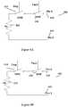
- FIG. 1Billustrates a particular example of a charging system according to the present invention.
- FIG. 2illustrates a rectifier or charger power unit according to some embodiments of the present invention.
- FIG. 3illustrates a pad land pattern for a rectifier or charger power unit bus according to some embodiments of the present invention.
- FIG. 4illustrates an equivalent circuit when a bus bar blade is utilized to determine the type of the power module shown in FIG. 2 .
- FIG. 5illustrates control circuits for a power module according to some embodiments of the present invention.
- FIGS. 6A and 6Billustrate resistance couplings for a rectifier and a charger power module, respectively.
- FIG. 7illustrates a fault signal generation circuit that can be utilized to indicate a fault in a power module.
- FIG. 8illustrates the sensing circuit utilized to determine the number of power modules configured as a particular type of power module according to some embodiments of the present invention.
- FIG. 9illustrates an embodiment of a controller for a charging system according to some embodiments of the present invention.
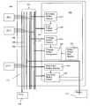
- FIG. 1Aillustrates a modular battery charger 100 according to some embodiments of the present invention.
- Modular battery charger 100includes any number of power modules 102 , of which power modules 102 - 1 through 102 -N, where N is the total number of power modules, are shown (referred to collectively as power modules 102 ).
- Each of power modules 102is coupled to a backplane 110 .
- Backplane 110is further coupled to a battery 112 .
- Battery 112receives a charging current from backplane 110 during charging.
- power modules 102are each formed on a circuit board and then inserted into one of a plurality of slots (not shown in the figure) in backplane 110 .
- backplane 110can include an array of slots that receives power modules 102 .
- Power modules 102may have multi-pin (alternatively referred to as terminals) edge connectors through which electrical connections are made with backplane 110 .
- Modular battery charger 100may be conveniently configured to charge a particular battery 112 by insuring that particular numbers of power modules 102 of particular types are inserted into backplane 110 . As such, modular battery charger 100 may include any number of power modules 102 .
- Battery 112may receive electrical energy from one or more of power modules 102 through backplane 110 .
- modular battery charger 100may be coupled to more than one battery.
- battery 112can be any type of battery.
- Battery charger 100may, for example, be a flow type battery.
- battery 100may be any device that stores electrical energy in any form, for example as chemical energy, mechanical energy, or directly as electrical energy.
- Power modules 102may include, for example, one or more modules from among the various types of modules.
- the types of power modules 102include, for example, charger modules, rectifier modules, buck-boost modules, sensor-interface modules, and controller modules.
- Each of power modules 102are coupled to backplane 110 through one or more terminals (or pins), through which they receive or supply one or more electrical signals to backplane 110 .
- power module 102 - k(an arbitrary one of power modules 102 ) may be a rectifier module that receives an AC voltage across two input terminals and provides a fixed DC voltage across two output terminals.
- each of power modules 102may include one or more terminals for sensing signals and one or more terminals for receiving control signals or providing control signals to backplane 110 .
- modular battery charging system 100can be utilized to improve reliability, maintainability, and flexibility of battery charging system 100 .
- Each of power modules 102performs one or more electrical functions associated with charging battery 112 , monitoring the charge on battery 112 , or supplying power to back-plane 110 and others of modules 102 .
- power modules 102can include rectifier modules, charger modules, buck-boost modules, sensor-interface modules, and controller modules.
- Power modules 102can include other types of modules as well. As such, an embodiment of modular battery charging system 100 can be tailored to meet the needs of any particular battery 112 to be charged.
- power modules 102may include multiple charger modules to ensure that the modular battery charging system continues to be functional even if one or more of the charger modules fails. Redundancy may be provided by either operating only one operational power modules among the multiple power modules of the same power module type at a time or by simultaneously operating multiple operational power modules of a particular power module type. For example, multiple charger modules may be operating simultaneously to provide, in sum, a total output charging current to charge battery 112 . Each charger module among the power modules 102 of modular battery charging system 100 provides a part of the total output charging current. As such, an electrical function of providing the total charging current is shared among the multiple active charger modules.
- FIG. 1Bshows an example of charger system 100 according to some embodiments of the present invention.
- poweris received either from an external power line 152 or a diesel generator 154 .
- external powercan be received from any source, including a power grid or dedicated generator such as a solar, tidal, wind, or other form of generator.
- the example of charger system 100 shown in FIG. 1Bincludes one rectifier power module, power module 102 - 1 , two charging power modules, i.e., power module 102 - 2 and power module 102 - 3 , and a buck-boost module, i.e., power module 102 - 4 .
- Electronics 160controls power modules 102 - 1 through 102 - 4 in order to charge battery 112 . Additionally, a lead-acid battery 162 and lead acid battery charger 156 are shown. In some systems, for example where battery 112 may not provide sufficient instantaneous current to start a device such as a motor, a lead acid battery such as battery 162 can be provided.
- FIGS. 2 through 5illustrate certain aspects of some embodiments of charger and rectifier power modules. These embodiments are illustrated here for illustrative purposes and are not intended to limit the scope of the invention in any way.
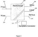
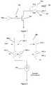
- FIG. 2illustrates a power module 200 that can be utilized as one of power modules 102 in FIG. 1 .
- Power module 200 shown in FIG. 2is a rectifier/charger module and can be configured as either a rectifier module or a charger module.
- both a rectifier and a charger modulereceives a fixed voltage between the P input bus 202 and the N input bus 204 .
- N input bus 204is the neutral bus while P input bus 202 is the phase line of an incoming power line.
- An output voltageis output to backplane 110 through either B-bus 206 , which is coupled to the B bus of backplane 110 , or C bus 208 , which is coupled to the charging bus in backplane 110 , depending on whether power module 200 is configured as a rectifier module or a charger module, respectively.
- the B bus in backplane 110is coupled to provide power to backplane 110 and other power modules 102 .
- the charging bus of backplane 110is coupled to provide charging current to battery 112 .
- a reference bus 210provides a common voltage line in backplane 110 .
- control buses 212are also utilized to couple power module 200 to backplane 110 and include control and monitoring lines.
- power module 200when power module 200 functions as a rectifier, it receives a fixed input voltage and outputs a fixed output voltage, for example 50V, on B bus 206 .
- power module 200 acting as a rectifiercan provide as much as 60 A of current.
- connectionsare made between backplane 110 and P bus 202 , N bus 204 , Reference bus 210 , and B bus 206 .
- a fixed AC input voltageis supplied between P bus 202 and N bus 204 .
- a fixed output voltageis supplied to C bus 208 in response to control signals from backplane 110 .
- the output voltagecan have a range of voltages. In some embodiments, for example, the output voltage on C bus 208 can range from about 30 V to about 70 V.
- the output current supplied to C bus 208is variable depending on the status of charging system 100 .
- connectionsare made between backplane 110 and P bus 202 , N bus 204 , Reference bus 210 , and C bus 208 .
- a difference between a rectifier and a chargerincludes the connection to B bus 206 or C bus 208 .
- Another differenceis the settings of output voltage and current supplied by power module 200 .
- some embodiments of power module 200can be configured as a rectifier by connecting to B bus 206 and appropriately adjusting the voltage and current settings and can be configured as a charger by connecting to C bus 208 and appropriately adjusting the voltage and current settings.
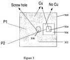
- FIG. 3illustrates a land pattern for a pad 300 that can be utilized for coupling output terminals of power charger 200 B bus 206 and C bus 208 of to backplane 110 .
- pad 300includes a first metallic cladded area 302 and a second metallic cladded area 304 surrounded by non-cladded area 306 in first metallic cladded area 302 .
- First metallic cladded area 302can be utilized to make electrical contact with the electronics of power module 200 .
- Second metallic cladded area 304can be utilized to make electrical contact with monitoring circuitry 400 , shown in FIG. 4 .
- a conducting bus bar blade(not shown) can be inserted, connected between first cladded area 302 and second cladded area 304 .
- a bus bar bladecan be a rigid conducting piece that electrically couples pad 300 to a bus.
- a bus bar bladecan be firmly attached to pad 300 by a screw inserted into screw hole 308 such that a portion of the bus bar blade is held in contact with second cladded area 304 .
- other arrangementscan also be utilized to electrically couple first cladded area 302 with second cladded area 304 and backplane 110 if pad 300 is to be utilized.
- a bus bar blade utilized to make the connection to B-bus 206 if power module 200 is being configured as a rectifier modulealso couples first cladded area 302 (P 1 ) with second cladded area 304 (P 2 ).
- a pad such as pad 300can also be utilized in the connection to C-bus 208 if power module 200 is being configured as a charger module.
- the bus bar bladewhen the bus bar blade is utilized to make the connection to C bus 208 , the bus bar blade also makes connection between cladded areas 302 and 304 .
- FIG. 4shows an equivalent circuit 400 illustrating an embodiment of power module 200 when power module 200 is configured as a rectifier by installing a bus bar blade to connect to B bus 206 .
- pad 300is represented by a switch between points P 1 (cladded area 302 ) and P 2 (cladded area 304 ).
- the voltage BTS V provided by power module 200is supplied to first cladded area 302 and, if the bus bar blade is installed, the switch is closed and voltage V is supplied to B bus 206 and to electrical circuit 400 .
- a voltage divider having resistors R 1 408 and R 2 410provide a signal Bsig that has a voltage proportional to the voltage V.
- the signal Bsigis held at a voltage determined by resistors 408 and 410 , for example 5 volts. If the bus bar blade is not installed, the signal Bsig is grounded through resistor 410 and has value 0.
- power module 200is configured to be either a charger module or a rectifier module. If Bsig is 0, then power module 200 is assumed to be a charger module and a signal Csig, through an inverter 412 , is asserted.
- a similar circuit to that shown in FIG. 4can be implemented on C bus 208 and the signal Csig can be independently determined.
- the signal Bsigis provided to switches SW 1 404 and SW 2 406 .
- Switches SW 1 404 and SW 2 406determine signals Chrg_V and Ref I. If Bsig is 0, indicating that no bus bar blade has been installed on pad 300 , then a voltage Cntr_V is coupled to Chrg_V and a voltage Cntr_I is coupled to Ref_I. If Bsig is non-zero, for example 5V, indicating that the bus bar blade has been installed in pad 300 and that voltage V is coupled to B bus 206 , then a voltage Fixed_V is connected to voltage Chrg_V at SW 1 404 and a voltage Fixed_I is connected to voltage Ref_I at SW 2 406 . Voltages Contr_V, Contr_I, Fixed_V, and Fixed_I are provided to power module 200 from a controller.
- the voltage Fixed_Vcan be generated using fixed resistors and is proportional to the voltage on B bus 206 .
- the voltage Fixed_Ican also be generated by fixed resistors and is proportional to the maximum current output on B bus 206 .
- the voltage Cntr_Vis generated by a controller board and utilized to control a charging power module.
- the voltage Cntr_Iis proportional to the output current generated by the controller board and is utilized to determine the charging current to be supplied by power module 200 if power module 200 is configured as a charging module.
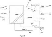
- FIG. 5illustrates the output stage of a charger/rectifier power module 200 as illustrated in FIG. 2 .
- a current sensor 502coupled between power module 200 and C bus 208 or B bus 206 provides a signal that is indicative of the current output from power module 200 .
- the signal from current sensor 502is compared with the Ref_I signal in a comparator 504 and an error signal is provided to power module 200 .
- the voltage Chrg_Vis input to power module 200 .
- Power module 200provides a current and a voltage in response to the error signal from comparator 504 and the Chrg_V signal.
- the Ref_I signal and the Chrg_V signalare determined by a controller, which may be another power module 102 or may be incorporated in backplane 110 , based on the status of system 100 .
- the signal Cntr_Iwhich as shown in FIG. 4 determines the signal Ref_I in power module 200 if power module 200 is configured as a charging module, is determined by the controller based on the number of power modules 102 that are configured as charging modules. The signal Cntr_I also is dependent on whether a fault condition has been detected in any of the charger modules.
- Power modules 102can be electrically coupled to backplane 110 through an edge connector on power module 102 that mates with a compatible backplane connector on backplane 110 .
- two pins on the backplane connectorare dedicated to each type of power module 102 .
- two pinsare dedicated to buck boost modules, different two pins are dedicated to rectifier modules, and yet another two pins are designated for charger modules.
- the presence or absence of a particular type of power module 102can be determined by monitoring the dedicated bus lines coupled to the dedicated pins associated with that type of power module 102 .
- Each active power module 102can provide a signal on the dedicated pins associated with its type.
- each of power modules 102couples a resistor of predetermined value across the appropriate pair of pins to indicate its presence.
- a resistive connection between the two pins dedicated for a particular type of power moduleindicates to a controller the presence of that type of module.
- a chargercan be indicated by the existence of a resistor between two particular pins on the backplane connector. The number of chargers present is then indicated by the number of parallel resistors present between those two pins on the backplane connector.
- FIGS. 6A and 6Billustrate resistance coupling for a rectifying module 600 and for a charging module 650 , respectively.
- switch 604if the Bsig signal is active, then switch 604 is closed. If no faults are detected with rectifying module 600 , then a switch 606 is also closed. When both switch 604 and switch 606 are closed, resistor 602 is coupled between pins 608 and 610 .
- Bsigis active when power module 200 is configured as a rectifier.
- a resistor 652 of charging module 650is connected between a pin 658 and a pin 660 when a switch 654 and a switch 656 are closed. Switch 654 is closed in response to the Csig signal, which is generated when charging module 650 is configured as a charging module.
- FIG. 7illustrates a fault signal generation circuit 700 .
- a fault signalcan be generated, for example, if there is no output voltage and no current drawn from a power module 200 . Opening switch 606 in a rectifier module or switch 656 in a charging module indicates to the controller board that the power module 600 or 650 , respectively, is no longer available. Also, an open collector signal is coupled to the backplane at a pin 708 or a pin 710 , depending on whether the signal Csig closes a switch 704 or signal Bsig closes a switch 706 .
- a fault signal on pins 708 or 710indicates that power module 200 has failed, a fault on pin 708 indicating that power module 200 is a failed charging module and a fault on pin 710 indicating that power module 200 is a failed rectifier module.
- Each power module 200 that is a charger or rectifier power modulecan include two pin connections, one for a charger fault and one for a rectifier fault signal. As shown in FIG. 7 , once a fault signal is generated, it is utilized to power the gate of a transistor 702 . The collector of transistor 702 is coupled to the fault detection pin 704 so that the fault can be detected by controller 160 .
- FIG. 8illustrates a sensing circuit for determining the number of power modules 202 of a particular type.
- Each active power module 202 of a particular typehas a resistor of a known value coupled between a known pair of pins.
- each of resistors 802 - 1 through 802 - nare coupled in parallel between the two lines on backplane 110 that correspond to the two pins.
- a controller cardcan then provide a voltage to one of the two pins in backplane 110 , and couple a constant current source 804 , which draws current Icc to ground, from the opposite of the two pins in backplane 110 .
- the voltage Vncan be utilized as a control voltage, for example control voltage Cntrl_V shown in FIG. 5 if circuit 800 is detecting charging modules. As further shown in FIG.
- fault switches 806 - 1 through 806 - n(which can be switches 606 or 656 shown in FIG. 6A or 6 B) can be utilized to remove individual ones of power modules 202 , and the reduction in the number of active power modules of a particular type detected by circuit 800 will be detected in voltage Vn.
- provision of an electrical functioncan be shared among multiple power modules 102 in the modular battery charging system 100 .
- Some embodiments of the present inventionautomatically configure each power module to provide one or more of an output voltage and an output current according to the current power requirements. For example, because provision of the total charging current to be supplied to battery 112 can be shared among the multiple charger modules, a portion of the charging current provided by each charger module can be determined. Further, power modules 102 , regardless of power module type, may be inserted in any of the available slots on the backplane. Some embodiments of the present invention can identify a power module inserted in a slot.
- a predefined set of electrical properties asserted on one or more terminals of each power modules 102is sensed to determine the type of that power module. Subsequently, a number of operational power modules corresponding to a particular type of power module 102 is determined, and based on the number of operational power modules, each power module corresponding to the power module type is configured to perform a portion of the charging task performed by that type of power module 102 .
- all of the duties for a particular module typecan be allocated to one module. In other embodiments, the duties of a particular module type can be distributed across all active modules of that type.
- the electrical energy received by battery 112is based on a power requirement for modular battery system 100 .
- the power requirementcorresponds to a charging voltage and a charging current provided to battery 112 .
- Each of the charging voltage and the charging currentis determined by factors which include, but are not limited to, rate of charging, and charge capacity of battery 112 .
- Other factors that may effect the charging voltage and charging currentinclude the number of battery cells in battery 112 and the rate of generation of hydrogen during the charging process.
- Each of power modules 102may be simultaneously operational. Additionally, each of power modules 102 configured as a charging module may provide a corresponding output current which, in sum, constitutes the charging current received by battery 112 . In other words, each of charging modules of the power modules 102 may be configured to provide a fraction of the charging current.
- FIG. 9illustrates a controller 902 that can be included in backplane 110 according to some embodiments of the present invention.
- controller 902can be included within backplane 110 .
- controller 902may be one or more of power modules 102 and can utilize one or more of the slots of backplane 110 .
- Controller 902may be implemented in any fashion, for example in hardware, software, or a combination of hardware and software.
- backplane 110includes conducting backplane lines 930 , each of which corresponds to a terminal on power modules 102 .
- Backplane lines 930includes power lines 904 , internal power lines 906 , charging current lines 908 , module identification lines 910 , and control lines 912 .
- each type of linemay include any number of individual lines.
- Power lines 904may be coupled to an external power source 928 such as a power grid or generator. Power lines 904 , for example, can be coupled to P bus 202 and N bus 204 as shown in FIG. 2 .
- Internal power lines 906provide power for controller 902 and for power modules 102 .
- Internal power lines 906may be coupled to B bus 206 and reference bus 210 shown in FIG. 2 .
- Power supplied to power lines 906can be provided by rectifier modules included as power modules 102 .
- Charging current lines 908provide the charging current used to charge battery 112 .
- Charging current lines 908can be coupled to C bus 208 shown in FIG. 2 .
- Current supplied to charging current lines 908can be provided by charging modules included as power modules 102 .
- Module identification lines 910are utilized to identify the number of types of power modules 102 that are coupled to backplane lines 916 . As discussed above, each type of power module 102 provides an electrical signal on one or more of module identification lines 910 . As shown in the embodiment illustrated in FIGS. 6A and 6B , for example, each type of power module 102 can provide a resistance between two of module identification lines 910 that are dedicated to that type of power module 102 . Power modules 102 according to embodiments of the present invention can utilize any indication of its type of module identification lines 910 , including, for example, a resistance, a capacitance, or other electrical signal.
- Control lines 912are utilized to control aspects of power modules 102 .
- the Cntrl_V and Cntrl_I signals shown in FIG. 5may be carried on control lines 912 .
- controller 902includes electronics to monitor and control power modules 102 .
- a rectifying module detector 914receives signals from module identification lines 910 and determines the number of power modules 102 that are configured as rectifying modules.
- a B-voltage control 916receives the number of rectifying modules from rectifying module detector 914 , monitors the voltage on input power lines 906 (the B bus), and provides control signals to control lines 912 to control the voltage and current output from each of power modules 102 configured as a rectifier module.
- a charging module detector 918is coupled to module identification lines 910 and detects the number of power modules 102 that are configured as charging modules.
- a charging module configuration 920is coupled to control lines 912 to control the current output of the power modules 102 configured as charging modules in response to the number of charging modules and signals from battery charge state monitor 922 .
- a battery charge state monitor 922is coupled to charging current lines 908 in order to monitor the current and voltage supplied to battery 110 .
- Charging module configuration 920controls the current supplied by charging modules, with each of the charging modules providing a portion of the current, in order to control the charging of battery 110 .
- a buck-boost module detector 924is coupled to module identification lines 910 and determines the number of buck-boost voltage modules included in power modules 102 .
- a buck-boost module control 926receives the number of buck-boost modules from buck-boost module detector 924 , monitors the voltage of current lines 908 , and controls the buck-boost modules in order to share control of current lines 908 , which can be utilized in both charging and discharging battery 112 .
- the buck boost modulecan be made bidirectional and then can control the charging using the above technique.
- the total load required to fulfill the charging dutycan be shared between the number of modules present.
- the current required to charge battery 110can be split between the number of available charging modules.
- the voltage and current supplied to internal power lines 906can be split between the number of rectifying modules included in power modules 102 .
- backplane 110can determine the number of each type of power module available in power modules 102 , independently of where those modules are actually inserted into the slots of backplane 110 . Further, in some embodiments, the charging, load for each type of power module is distributed between all available power modules of that type in power modules 102 . Further, if one or more of power modules 102 fail, that failure is detected and represented as a decrease in the number of available modules of that type. The load requirements are then redistributed amongst the remaining available power modules of that type.
- B-bus voltage control 916 , charging module control 920 , and buck-boost module control 926may utilize any type of feedback loop, including analog or digital loops (eg: RS232, I2C, SPI, or other forms of control). Further, controller 902 may include processors where B-bus voltage control 916 , charging module control 920 , and buck-boost module control 926 are implemented in software, hardware, or a combination of software and hardware.
Landscapes
- Engineering & Computer Science (AREA)
- Power Engineering (AREA)
- Business, Economics & Management (AREA)
- Emergency Management (AREA)
- Charge And Discharge Circuits For Batteries Or The Like (AREA)
- Secondary Cells (AREA)
Abstract
Description
Claims (19)
Priority Applications (2)
| Application Number | Priority Date | Filing Date | Title |
|---|---|---|---|
| US12/074,110US8587150B2 (en) | 2008-02-28 | 2008-02-28 | Method and modular system for charging a battery |
| PCT/US2009/001303WO2009108381A1 (en) | 2008-02-28 | 2009-02-26 | Battery charger |
Applications Claiming Priority (1)
| Application Number | Priority Date | Filing Date | Title |
|---|---|---|---|
| US12/074,110US8587150B2 (en) | 2008-02-28 | 2008-02-28 | Method and modular system for charging a battery |
Publications (2)
| Publication Number | Publication Date |
|---|---|
| US20090218984A1 US20090218984A1 (en) | 2009-09-03 |
| US8587150B2true US8587150B2 (en) | 2013-11-19 |
Family
ID=40677798
Family Applications (1)
| Application Number | Title | Priority Date | Filing Date |
|---|---|---|---|
| US12/074,110Expired - Fee RelatedUS8587150B2 (en) | 2008-02-28 | 2008-02-28 | Method and modular system for charging a battery |
Country Status (2)
| Country | Link |
|---|---|
| US (1) | US8587150B2 (en) |
| WO (1) | WO2009108381A1 (en) |
Cited By (5)
| Publication number | Priority date | Publication date | Assignee | Title |
|---|---|---|---|---|
| US20150229141A1 (en)* | 2012-08-08 | 2015-08-13 | Redflow R & D Pty Ltd | Flowing electrolyte battery maintenance bus system and method |
| US9444281B2 (en)* | 2014-01-03 | 2016-09-13 | Apple Inc. | Unified high power and low power battery charger |
| US9535472B1 (en)* | 2012-03-31 | 2017-01-03 | Western Digital Technologies, Inc. | Redundant power backplane for NAS storage device |
| US10777836B1 (en) | 2019-05-20 | 2020-09-15 | Creek Channel Inc. | Fe—Cr redox flow battery systems including a balance arrangement and methods of manufacture and operation |
| US11710844B2 (en) | 2020-11-16 | 2023-07-25 | Cougar Creek Technologies, Llc | Fe-Cr redox flow battery systems and methods utilizing chromium complexes with nitrogen-containing ligands |
Families Citing this family (39)
| Publication number | Priority date | Publication date | Assignee | Title |
|---|---|---|---|---|
| MX2008009309A (en) | 2006-01-20 | 2008-10-17 | Liquid Robotics Inc | Wave power. |
| AU2008223557B2 (en) | 2007-03-02 | 2013-10-24 | Liquid Robotics, Inc. | Wave power |
| US8587150B2 (en) | 2008-02-28 | 2013-11-19 | Deeya Energy, Inc. | Method and modular system for charging a battery |
| US8236463B2 (en)* | 2008-10-10 | 2012-08-07 | Deeya Energy, Inc. | Magnetic current collector |
| WO2010042899A1 (en)* | 2008-10-10 | 2010-04-15 | Deeya Energy Technology, Inc. | Flexible multi-walled tubing assembly |
| US20100092843A1 (en)* | 2008-10-10 | 2010-04-15 | Deeya Energy Technologies, Inc. | Venturi pumping system in a hydrogen gas circulation of a flow battery |
| US8230736B2 (en)* | 2008-10-10 | 2012-07-31 | Deeya Energy, Inc. | Level sensor for conductive liquids |
| US8883297B2 (en)* | 2008-10-10 | 2014-11-11 | Imergy Power Systems, Inc. | Methods for bonding porous flexible membranes using solvent |
| EP2351184A4 (en)* | 2008-10-10 | 2014-07-09 | Deeya Energy Technologies Inc | Method and apparatus for determining state of charge of a battery |
| US8587255B2 (en) | 2009-05-28 | 2013-11-19 | Deeya Energy, Inc. | Control system for a flow cell battery |
| CN102460812B (en)* | 2009-05-28 | 2014-12-31 | 艾默吉电力系统股份有限公司 | Preparation of flow battery electrolytes from raw materials |
| EP2436080A2 (en)* | 2009-05-28 | 2012-04-04 | Deeya Energy, Inc. | Electrolyte compositions |
| WO2010138949A2 (en)* | 2009-05-28 | 2010-12-02 | Deeya Energy, Inc. | Optical leak detection sensor |
| WO2010138942A2 (en) | 2009-05-28 | 2010-12-02 | Deeya Energy, Inc. | Redox flow cell rebalancing |
| WO2010138948A2 (en)* | 2009-05-28 | 2010-12-02 | Deeya Energy, Inc. | Buck-boost control circuit |
| WO2010138947A2 (en)* | 2009-05-29 | 2010-12-02 | Deeya Energy, Inc. | Methods of producing hydrochloric acid from hydrogen gas and chlorine gas |
| US8951665B2 (en)* | 2010-03-10 | 2015-02-10 | Imergy Power Systems, Inc. | Methods for the preparation of electrolytes for chromium-iron redox flow batteries |
| WO2011143158A2 (en)* | 2010-05-13 | 2011-11-17 | Coda Automotive, Inc. | Battery charging using multiple chargers |
| US9281535B2 (en) | 2010-08-12 | 2016-03-08 | Imergy Power Systems, Inc. | System dongle |
| US9106980B2 (en) | 2011-01-13 | 2015-08-11 | Imergy Power Systems, Inc. | Communications system |
| US8541121B2 (en) | 2011-01-13 | 2013-09-24 | Deeya Energy, Inc. | Quenching system |
| US9269982B2 (en) | 2011-01-13 | 2016-02-23 | Imergy Power Systems, Inc. | Flow cell stack |
| SG193480A1 (en) | 2011-03-17 | 2013-10-30 | Liquid Robotics Inc | Wave-powered devices configured for nesting |
| WO2013003640A1 (en) | 2011-06-28 | 2013-01-03 | Liquid Robotics Inc. | Watercraft that harvest both locomotive thrust and electrical power from wave motion |
| JP5737786B2 (en)* | 2011-10-11 | 2015-06-17 | ニチコン株式会社 | Stationary charging system |
| WO2014039731A1 (en) | 2012-09-05 | 2014-03-13 | Energy Storage Systems, Inc. | Redox and plating electrode systems for an all-iron hybrid flow battery |
| US9685651B2 (en) | 2012-09-05 | 2017-06-20 | Ess Tech, Inc. | Internally manifolded flow cell for an all-iron hybrid flow battery |
| TWI475361B (en)* | 2012-10-09 | 2015-03-01 | Wistron Corp | Current distribution system, current distribution method, and computer system thereof |
| US10005535B2 (en) | 2013-03-15 | 2018-06-26 | Liquid Robotics, Inc. | Adaptable modular power system (AMPS) and dedicated connector; modular payload boxes and autonomous water vehicle configured to accept same |
| US9533740B2 (en) | 2013-03-15 | 2017-01-03 | Liquid Robotics, Inc. | Adaptable modular power system (AMPS) |
| AU2013201985B2 (en)* | 2013-03-26 | 2015-02-19 | Empower Energy Pty Ltd | Power module system |
| CN104035892B (en)* | 2014-06-17 | 2017-05-03 | 英业达科技有限公司 | Server system |
| EP3189585A1 (en)* | 2014-09-02 | 2017-07-12 | Apple Inc. | Multi-phase battery charging with boost bypass |
| JP6370740B2 (en)* | 2015-05-18 | 2018-08-08 | エスペック株式会社 | Power supply device and charge / discharge test device |
| US10097017B2 (en) | 2015-06-24 | 2018-10-09 | Apple Inc. | Systems and methods for bidirectional two-port battery charging with boost functionality |
| US10778026B2 (en) | 2016-09-23 | 2020-09-15 | Apple Inc. | Multi-phase buck-boost charger |
| CN108001246B (en)* | 2016-11-01 | 2023-08-01 | 宇通客车股份有限公司 | Electric automobile direct current charging system and charging control method thereof |
| KR102181491B1 (en)* | 2019-06-04 | 2020-11-23 | 강재봉 | Chamber integral electrical test system |
| EP3754806A1 (en) | 2019-06-19 | 2020-12-23 | UTC Fire & Security EMEA BVBA | Power supply device |
Citations (122)
| Publication number | Priority date | Publication date | Assignee | Title |
|---|---|---|---|---|
| US3540934A (en) | 1967-07-11 | 1970-11-17 | Jan Boeke | Multiple cell redox battery |
| US3996064A (en) | 1975-08-22 | 1976-12-07 | The United States Of America As Represented By The Administrator Of The National Aeronautics And Space Administration | Electrically rechargeable REDOX flow cell |
| US4133941A (en) | 1977-03-10 | 1979-01-09 | The United States Of America As Represented By The Administrator Of The National Aeronautics And Space Administration | Formulated plastic separators for soluble electrode cells |
| US4159366A (en) | 1978-06-09 | 1979-06-26 | The United States Of America As Represented By The Administrator Of The National Aeronautics And Space Administration | Electrochemical cell for rebalancing redox flow system |
| US4309372A (en) | 1977-03-10 | 1982-01-05 | The United States Of America As Represented By The Administrator Of The National Aeronautics And Space Administration | Method of making formulated plastic separators for soluble electrode cells |
| US4312735A (en) | 1979-11-26 | 1982-01-26 | Exxon Research & Engineering Co. | Shunt current elimination |
| US4414090A (en) | 1981-10-01 | 1983-11-08 | Rai Research Corporation | Separator membranes for redox-type electrochemical cells |
| US4454649A (en) | 1982-02-26 | 1984-06-19 | The United States Of America As Represented By The Administrator Of The National Aeronautics And Space Administration | Chromium electrodes for REDOX cells |
| US4468441A (en) | 1981-10-01 | 1984-08-28 | Rai Research Corp. | Separator membranes for redox-type electrochemical cells |
| US4485154A (en) | 1981-09-08 | 1984-11-27 | Institute Of Gas Technology | Electrically rechargeable anionically active reduction-oxidation electrical storage-supply system |
| US4496637A (en) | 1982-12-27 | 1985-01-29 | Toyo Boseki Kabushiki Kaisha | Electrode for flowcell |
| JPS6047373A (en) | 1983-08-26 | 1985-03-14 | Sumitomo Electric Ind Ltd | redox battery |
| JPS6070672A (en) | 1983-09-26 | 1985-04-22 | Agency Of Ind Science & Technol | Method of operating redox-flow secondary battery |
| JPS60115174A (en) | 1983-11-25 | 1985-06-21 | Mitsui Eng & Shipbuild Co Ltd | Method of preparing solution for redox-flow battery |
| US4543302A (en) | 1984-08-20 | 1985-09-24 | The United States Of America As Represented By The Administrator Of The National Aeronautics And Space Administration | Negative electrode catalyst for the iron chromium REDOX energy storage system |
| US4732827A (en) | 1985-07-05 | 1988-03-22 | Japan Metals And Chemical Co., Ltd. | Process for producing electrolyte for redox cell |
| US4784924A (en) | 1981-06-08 | 1988-11-15 | University Of Akron | Metal-halogen energy storage device and system |
| US4814241A (en) | 1986-03-15 | 1989-03-21 | Director-General, Agency Of Industrial Science And Technology | Electrolytes for redox flow batteries |
| US4828666A (en) | 1987-02-16 | 1989-05-09 | Toyo Boseki Kabushiki Kaisha (Trading Under Toyo Co., Ltd.) | Electrode for flow-through type electrolytic cell |
| US4874483A (en) | 1988-02-04 | 1989-10-17 | Chiyoda Corporation | Process for the preparation of redox battery electrolyte and recovery of lead chloride |
| US4882241A (en) | 1987-10-23 | 1989-11-21 | Siemens Aktiengesellschaft | Redox battery |
| US4894294A (en) | 1984-06-05 | 1990-01-16 | The Furukawa Electric Co., Ltd. | Electrolytic solution supply type battery |
| US4929325A (en) | 1988-09-08 | 1990-05-29 | Globe-Union Inc. | Removable protective electrode in a bipolar battery |
| US4945019A (en) | 1988-09-20 | 1990-07-31 | Globe-Union Inc. | Friction welded battery component |
| US4948681A (en) | 1988-05-02 | 1990-08-14 | Globe-Union Inc. | Terminal electrode |
| US4956244A (en) | 1988-06-03 | 1990-09-11 | Sumitomo Electric Industries, Ltd. | Apparatus and method for regenerating electrolyte of a redox flow battery |
| US5061578A (en) | 1985-10-31 | 1991-10-29 | Kabushiki Kaisha Meidensha | Electrolyte circulation type secondary battery operating method |
| US5119011A (en) | 1990-08-08 | 1992-06-02 | General Electric Company | Battery state of charge indicator |
| US5162168A (en) | 1991-08-19 | 1992-11-10 | Magnavox Electronic Systems Company | Automatic voltage control system and method for forced electrolyte flow batteries |
| US5188911A (en) | 1991-02-25 | 1993-02-23 | Magnavox Electronic Systems Company | Tapered manifold for batteries requiring forced electrolyte flow |
| US5258241A (en) | 1988-12-22 | 1993-11-02 | Siemens Aktiengesellschaft | Rebalance cell for a Cr/Fe redox storage system |
| US5366827A (en) | 1992-06-10 | 1994-11-22 | Digital Equipment Corporation | Modular housing for batteries and battery charger |
| US5366824A (en) | 1992-10-21 | 1994-11-22 | Agency Of Industrial Science & Technology, Ministry Of International Trade & Industry | Flow battery |
| EP0696831A2 (en) | 1994-08-10 | 1996-02-14 | York Technologies, Inc | Modular power supply system |
| US5648184A (en) | 1995-04-13 | 1997-07-15 | Toyo Boseki Kabushiki Kaisha | Electrode material for flow-through type electrolytic cell, wherein the electrode comprises carbonaceous material having at least one groove |
| US5656390A (en) | 1995-02-16 | 1997-08-12 | Kashima-Kita Electric Power Corporation | Redox battery |
| US5665212A (en) | 1992-09-04 | 1997-09-09 | Unisearch Limited Acn 000 263 025 | Flexible, conducting plastic electrode and process for its preparation |
| US5759711A (en) | 1996-02-19 | 1998-06-02 | Kashima-Kita Electric Power Corporation | Liquid-circulating battery |
| US5847566A (en) | 1994-09-16 | 1998-12-08 | Seiko Epson Corporation | Battery capacity calculation method |
| US5851694A (en) | 1996-06-19 | 1998-12-22 | Kashima-Kita Electric Power Corporation | Redox flow type battery |
| US5949219A (en) | 1998-07-24 | 1999-09-07 | The United States Of America As Represented By The United States Department Of Energy | Optical state-of-charge monitor for batteries |
| US6005183A (en) | 1995-12-20 | 1999-12-21 | Ebara Corporation | Device containing solar cell panel and storage battery |
| JP2000058099A (en) | 1998-08-04 | 2000-02-25 | Sumitomo Electric Ind Ltd | Redox flow battery diaphragm |
| JP3017963B2 (en) | 1997-09-12 | 2000-03-13 | 株式会社三五 | Silencer |
| US6037749A (en) | 1995-06-21 | 2000-03-14 | Batteryguard Limited | Battery monitor |
| US6040075A (en) | 1994-12-17 | 2000-03-21 | Loughborough University Of Technology | Electrolytic and fuel cell arrangements |
| WO2000017991A1 (en) | 1998-09-23 | 2000-03-30 | Ro Associates, Inc. | Improved current sharing signal coupling/decoupling circuit for power converter systems |
| US6086643A (en) | 1995-12-28 | 2000-07-11 | National Power Plc | Method for the fabrication of electrochemical cells |
| JP2000200619A (en) | 1999-01-08 | 2000-07-18 | Kashimakita Kyodo Hatsuden Kk | Redox battery |
| US6236582B1 (en) | 2000-02-01 | 2001-05-22 | Micro Linear Corporation | Load share controller for balancing current between multiple supply modules |
| JP2002015762A (en) | 2000-06-28 | 2002-01-18 | Sumitomo Electric Ind Ltd | Redox flow battery |
| JP2002175822A (en) | 2000-12-07 | 2002-06-21 | Sumitomo Electric Ind Ltd | Redox flow battery and method of operating the same |
| JP2002289233A (en) | 2001-03-23 | 2002-10-04 | Hitachi Zosen Corp | Redox flow battery tank |
| US6461772B1 (en) | 1998-12-14 | 2002-10-08 | Sumitomo Electric Industries, Ltd. | Battery diaphragm |
| US6475661B1 (en) | 1998-01-28 | 2002-11-05 | Squirrel Holdings Ltd | Redox flow battery system and cell stack |
| JP2002367661A (en) | 2001-06-12 | 2002-12-20 | Sumitomo Electric Ind Ltd | Assembling method of redox flow battery |
| US20030008203A1 (en) | 2001-07-05 | 2003-01-09 | Rick Winter | Leak sensor for flowing electrolyte batteries |
| US6507169B1 (en) | 1998-06-09 | 2003-01-14 | Farnow Technologies Pty Limited | Energy storage system |
| US6509119B1 (en) | 1999-06-11 | 2003-01-21 | Toyo Boseki Kabushiki Kaisha | Carbon electrode material for a vanadium-based redox-flow battery |
| US6524452B1 (en) | 1998-09-29 | 2003-02-25 | Regenesys Technologies Limited | Electrochemical cell |
| US6555267B1 (en) | 1999-07-01 | 2003-04-29 | Squirrel Holding Ltd. | Membrane-separated, bipolar multicell electrochemical reactor |
| US6562514B1 (en) | 1993-11-17 | 2003-05-13 | Pinnacle Vrb Limited | Stabilized vanadium electrolyte solutions for all-vanadium redox cells and batteries |
| JP2003173812A (en) | 2001-12-04 | 2003-06-20 | Sumitomo Electric Ind Ltd | Redox flow battery capacity drop detection method |
| US6692862B1 (en) | 2000-03-31 | 2004-02-17 | Squirrel Holdings Ltd. | Redox flow battery and method of operating it |
| US20040070370A1 (en) | 2001-08-03 | 2004-04-15 | Katsuji Emura | Method for operating power source system and power source system comprising secondary battery |
| US6759158B2 (en) | 2002-01-03 | 2004-07-06 | Premium Power Corporation | System for proclusion of electrical shorting |
| US6761945B1 (en) | 1999-04-28 | 2004-07-13 | Sumitomo Electric Industries, Ltd. | Electrolyte tank and manufacturing method thereof |
| US6764789B1 (en) | 1999-09-27 | 2004-07-20 | Sumitomo Electric Industries, Ltd. | Redox flow battery |
| US20040168818A1 (en)* | 2002-01-17 | 2004-09-02 | Powerware Corporation | System for detecting defective battery packs |
| US20040170893A1 (en) | 2001-06-12 | 2004-09-02 | Hiroyuki Nakaishi | Cell frame for redox flow cell and redox flow cell |
| US6787259B2 (en)* | 2002-09-12 | 2004-09-07 | Metallic Power, Inc. | Secondary power source for use in a back-up power system |
| WO2004079849A1 (en) | 2003-03-04 | 2004-09-16 | Squirrel Holdings Ltd. | Multi voltage tap redox flow battery composed of stacked cell modules of adjustable cell area |
| EP1462813A2 (en) | 2000-03-29 | 2004-09-29 | Powerware Corporation | System for detecting defective battery packs |
| US20040202915A1 (en) | 2001-06-12 | 2004-10-14 | Hiroyuki Nakaishi | Cell frame for redox-flow cell and redox-flow cell |
| US20040241544A1 (en) | 2001-06-12 | 2004-12-02 | Hiroyuki Nakaishi | Cell stack for flow cell |
| US20050074653A1 (en) | 2001-06-28 | 2005-04-07 | Squirrel Holdings Ltd. | Redox cell with non-selective permionic separator |
| JP2005142056A (en) | 2003-11-07 | 2005-06-02 | Kansai Electric Power Co Inc:The | Redox flow battery system |
| US6905797B2 (en) | 2001-04-12 | 2005-06-14 | Squirrel Holdings Ltd. | Porous mat electrodes for electrochemical reactor having electrolyte solution distribution channels |
| US20050158615A1 (en) | 2002-02-14 | 2005-07-21 | Samuel John M.G. | Redox flow battery |
| US20050156432A1 (en) | 2004-01-15 | 2005-07-21 | Hennessy Timothy D.J. | Power generation system incorporating a vanadium redox battery and a direct current wind turbine generator |
| US20050156431A1 (en) | 2004-01-15 | 2005-07-21 | Hennessy Timothy D.J. | Vanadium redox battery energy storage and power generation system incorporating and optimizing diesel engine generators |
| US20050164075A1 (en) | 2002-04-23 | 2005-07-28 | Takahiro Kumamoto | Method for operating redox flow battery and redox flow battery cell stack |
| US20050181273A1 (en) | 2002-04-23 | 2005-08-18 | Hiroshige Deguchi | Method for designing redox flow battery system |
| JP2005228633A (en) | 2004-02-13 | 2005-08-25 | Sumitomo Electric Ind Ltd | Redox flow battery cell and redox flow battery |
| JP2005228622A (en) | 2004-02-13 | 2005-08-25 | Sumitomo Electric Ind Ltd | Redox flow battery cell |
| US6940255B2 (en) | 2003-10-23 | 2005-09-06 | Cardiac Pacemakers, Inc. | Battery charge indicator such as for an implantable medical device |
| JP2005322447A (en) | 2004-05-06 | 2005-11-17 | Kansai Electric Power Co Inc:The | Operation method of redox flow battery system |
| US20050260473A1 (en) | 2004-05-21 | 2005-11-24 | Sarnoff Corporation | Electrical power source designs and components |
| US6986966B2 (en) | 2001-08-10 | 2006-01-17 | Plurion Systems, Inc. | Battery with bifunctional electrolyte |
| US20060014054A1 (en) | 2004-07-19 | 2006-01-19 | The Kansai Electric Power Co., Inc. | Stable power supplying apparatus |
| JP2006107988A (en) | 2004-10-07 | 2006-04-20 | Kansai Electric Power Co Inc:The | Apparatus and method for detecting charge capacity |
| JP2006114360A (en) | 2004-10-14 | 2006-04-27 | Kansai Electric Power Co Inc:The | Operation method of redox flow battery system |
| US20060092588A1 (en) | 2004-10-28 | 2006-05-04 | Realmuto Richard A | Multiple bi-directional input/output power control system |
| US7046531B2 (en) | 2001-07-11 | 2006-05-16 | Squirrel Holdings Ltd. | Transformerless static voltage inverter for battery systems |
| JP2006147306A (en) | 2004-11-18 | 2006-06-08 | Sumitomo Electric Ind Ltd | Operation method of redox flow battery system |
| JP2006147376A (en) | 2004-11-19 | 2006-06-08 | Kansai Electric Power Co Inc:The | Redox flow battery |
| US7061205B2 (en) | 2002-04-23 | 2006-06-13 | Sumitomo Electric Industries, Ltd. | Method for operating redox flow battery system |
| US7078123B2 (en) | 1995-05-03 | 2006-07-18 | Vrb Power Systems, Inc. | High energy density vanadium electrolyte solutions, methods of preparation thereof and all-vanadium redox cells and batteries containing high energy vanadium electrolyte solutions |
| DE102006007206A1 (en) | 2006-02-15 | 2006-10-12 | Henze, Werner | Redox battery for power supply has chambers containing electrolytes that are separated by special wall, where wall acting as electrically conducting intermediate electrode is permeable only for hydrogen |
| JP2006313691A (en) | 2005-05-09 | 2006-11-16 | Sumitomo Electric Ind Ltd | Redox flow battery system |
| JP2006351346A (en) | 2005-06-15 | 2006-12-28 | Kansai Electric Power Co Inc:The | Redox flow battery system |
| WO2006135958A1 (en) | 2005-06-20 | 2006-12-28 | V-Fuel Pty Ltd | Improved perfluorinated membranes and improved electrolytes for redox cells and batteries |
| US7181183B1 (en) | 2006-01-27 | 2007-02-20 | Vrb Power Systems Inc. | Telecommunication system incorporating a vanadium redox battery energy storage system |
| US7184903B1 (en) | 2006-03-16 | 2007-02-27 | Vrb Power Systems Inc. | System and method for a self-healing grid using demand side management techniques and energy storage |
| US20070072067A1 (en) | 2005-09-23 | 2007-03-29 | Vrb Power Systems Inc. | Vanadium redox battery cell stack |
| US7199550B2 (en) | 2001-05-01 | 2007-04-03 | Sumitomo Electric Industries, Ltd. | Method of operating a secondary battery system having first and second tanks for reserving electrolytes |
| JP2007087829A (en) | 2005-09-22 | 2007-04-05 | Sumitomo Electric Ind Ltd | Redox flow battery system |
| US20070080666A1 (en) | 2005-10-10 | 2007-04-12 | General Electric Company | Methods and apparatus for coupling an energy storage system to a variable energy supply system |
| US20070111089A1 (en) | 2005-08-30 | 2007-05-17 | Railpower Technologies Corp. | Electrochemical cell for hybrid electric vehicle applications |
| US7220515B2 (en) | 2000-12-06 | 2007-05-22 | Sumitomo Electric Industries, Ltd. | Pressure fluctuation prevention tank structure, electrolyte circulation type secondary battery, and redox flow type secondary battery |
| US7227275B2 (en) | 2005-02-01 | 2007-06-05 | Vrb Power Systems Inc. | Method for retrofitting wind turbine farms |
| US20080193828A1 (en) | 2007-02-12 | 2008-08-14 | Saroj Kumar Sahu | Apparatus and Methods of Determination of State of Charge in a Redox Flow Battery |
| US20090218984A1 (en) | 2008-02-28 | 2009-09-03 | Deeya Energy, Inc. | Battery charger |
| US20100003586A1 (en) | 2008-07-01 | 2010-01-07 | Deeya Energy, Inc. A California C-Corp | Redox flow cell |
| US20100094468A1 (en) | 2008-10-10 | 2010-04-15 | Deeya Energy, Incorporated | Level Sensor for Conductive Liquids |
| US20100090651A1 (en) | 2008-10-10 | 2010-04-15 | Deeya Energy Technologies, Inc. | Method and apparatus for determining state of charge of a battery |
| US20100092813A1 (en) | 2008-10-10 | 2010-04-15 | Saroj Kumar Sahu | Thermal Control of a Flow Cell Battery |
| US20100092807A1 (en) | 2008-10-10 | 2010-04-15 | Saroj Kumar Sahu | Magnetic Current Collector |
| US20100092843A1 (en) | 2008-10-10 | 2010-04-15 | Deeya Energy Technologies, Inc. | Venturi pumping system in a hydrogen gas circulation of a flow battery |
| US20100092757A1 (en) | 2008-10-10 | 2010-04-15 | Deeya Energy Technologies, Inc. | Methods for Bonding Porous Flexible Membranes Using Solvent |
| US20100136455A1 (en) | 2008-10-10 | 2010-06-03 | Rick Winter | Common Module Stack Component Design |
| US20100143781A1 (en) | 2008-12-05 | 2010-06-10 | Majid Keshavarz | Methods for the preparation and purification of electrolytes for redox flow batteries |
Family Cites Families (4)
| Publication number | Priority date | Publication date | Assignee | Title |
|---|---|---|---|---|
| US2004200A (en)* | 1931-10-02 | 1935-06-11 | Union Switch & Signal Co | Lamp socket adapter |
| DE69632422T2 (en)* | 1995-08-11 | 2005-05-19 | Zenon Environmental Inc., Oakville | Process for embedding hollow fiber membranes |
| US7131312B2 (en)* | 2000-12-25 | 2006-11-07 | Yamaha Hatsudoki Kabushiki Kaisha | Pipe bending apparatus and method |
| US7512583B2 (en)* | 2005-05-03 | 2009-03-31 | Palomar Technology, Llc | Trusted decision support system and method |
- 2008
- 2008-02-28USUS12/074,110patent/US8587150B2/ennot_activeExpired - Fee Related
- 2009
- 2009-02-26WOPCT/US2009/001303patent/WO2009108381A1/enactiveApplication Filing
Patent Citations (123)
| Publication number | Priority date | Publication date | Assignee | Title |
|---|---|---|---|---|
| US3540934A (en) | 1967-07-11 | 1970-11-17 | Jan Boeke | Multiple cell redox battery |
| US3996064A (en) | 1975-08-22 | 1976-12-07 | The United States Of America As Represented By The Administrator Of The National Aeronautics And Space Administration | Electrically rechargeable REDOX flow cell |
| US4133941A (en) | 1977-03-10 | 1979-01-09 | The United States Of America As Represented By The Administrator Of The National Aeronautics And Space Administration | Formulated plastic separators for soluble electrode cells |
| US4309372A (en) | 1977-03-10 | 1982-01-05 | The United States Of America As Represented By The Administrator Of The National Aeronautics And Space Administration | Method of making formulated plastic separators for soluble electrode cells |
| US4159366A (en) | 1978-06-09 | 1979-06-26 | The United States Of America As Represented By The Administrator Of The National Aeronautics And Space Administration | Electrochemical cell for rebalancing redox flow system |
| US4312735A (en) | 1979-11-26 | 1982-01-26 | Exxon Research & Engineering Co. | Shunt current elimination |
| US4784924A (en) | 1981-06-08 | 1988-11-15 | University Of Akron | Metal-halogen energy storage device and system |
| US4485154A (en) | 1981-09-08 | 1984-11-27 | Institute Of Gas Technology | Electrically rechargeable anionically active reduction-oxidation electrical storage-supply system |
| US4468441A (en) | 1981-10-01 | 1984-08-28 | Rai Research Corp. | Separator membranes for redox-type electrochemical cells |
| US4414090A (en) | 1981-10-01 | 1983-11-08 | Rai Research Corporation | Separator membranes for redox-type electrochemical cells |
| US4454649A (en) | 1982-02-26 | 1984-06-19 | The United States Of America As Represented By The Administrator Of The National Aeronautics And Space Administration | Chromium electrodes for REDOX cells |
| US4496637A (en) | 1982-12-27 | 1985-01-29 | Toyo Boseki Kabushiki Kaisha | Electrode for flowcell |
| JPS6047373A (en) | 1983-08-26 | 1985-03-14 | Sumitomo Electric Ind Ltd | redox battery |
| JPS6070672A (en) | 1983-09-26 | 1985-04-22 | Agency Of Ind Science & Technol | Method of operating redox-flow secondary battery |
| JPS60115174A (en) | 1983-11-25 | 1985-06-21 | Mitsui Eng & Shipbuild Co Ltd | Method of preparing solution for redox-flow battery |
| US4894294A (en) | 1984-06-05 | 1990-01-16 | The Furukawa Electric Co., Ltd. | Electrolytic solution supply type battery |
| US4543302A (en) | 1984-08-20 | 1985-09-24 | The United States Of America As Represented By The Administrator Of The National Aeronautics And Space Administration | Negative electrode catalyst for the iron chromium REDOX energy storage system |
| US4732827A (en) | 1985-07-05 | 1988-03-22 | Japan Metals And Chemical Co., Ltd. | Process for producing electrolyte for redox cell |
| US5061578A (en) | 1985-10-31 | 1991-10-29 | Kabushiki Kaisha Meidensha | Electrolyte circulation type secondary battery operating method |
| US4814241A (en) | 1986-03-15 | 1989-03-21 | Director-General, Agency Of Industrial Science And Technology | Electrolytes for redox flow batteries |
| US4828666A (en) | 1987-02-16 | 1989-05-09 | Toyo Boseki Kabushiki Kaisha (Trading Under Toyo Co., Ltd.) | Electrode for flow-through type electrolytic cell |
| US4882241A (en) | 1987-10-23 | 1989-11-21 | Siemens Aktiengesellschaft | Redox battery |
| US4874483A (en) | 1988-02-04 | 1989-10-17 | Chiyoda Corporation | Process for the preparation of redox battery electrolyte and recovery of lead chloride |
| US4948681A (en) | 1988-05-02 | 1990-08-14 | Globe-Union Inc. | Terminal electrode |
| US4956244A (en) | 1988-06-03 | 1990-09-11 | Sumitomo Electric Industries, Ltd. | Apparatus and method for regenerating electrolyte of a redox flow battery |
| US4929325A (en) | 1988-09-08 | 1990-05-29 | Globe-Union Inc. | Removable protective electrode in a bipolar battery |
| US4945019A (en) | 1988-09-20 | 1990-07-31 | Globe-Union Inc. | Friction welded battery component |
| US5258241A (en) | 1988-12-22 | 1993-11-02 | Siemens Aktiengesellschaft | Rebalance cell for a Cr/Fe redox storage system |
| US5119011A (en) | 1990-08-08 | 1992-06-02 | General Electric Company | Battery state of charge indicator |
| US5188911A (en) | 1991-02-25 | 1993-02-23 | Magnavox Electronic Systems Company | Tapered manifold for batteries requiring forced electrolyte flow |
| US5162168A (en) | 1991-08-19 | 1992-11-10 | Magnavox Electronic Systems Company | Automatic voltage control system and method for forced electrolyte flow batteries |
| US5366827A (en) | 1992-06-10 | 1994-11-22 | Digital Equipment Corporation | Modular housing for batteries and battery charger |
| US5665212A (en) | 1992-09-04 | 1997-09-09 | Unisearch Limited Acn 000 263 025 | Flexible, conducting plastic electrode and process for its preparation |
| US5366824A (en) | 1992-10-21 | 1994-11-22 | Agency Of Industrial Science & Technology, Ministry Of International Trade & Industry | Flow battery |
| US6562514B1 (en) | 1993-11-17 | 2003-05-13 | Pinnacle Vrb Limited | Stabilized vanadium electrolyte solutions for all-vanadium redox cells and batteries |
| EP0696831A2 (en) | 1994-08-10 | 1996-02-14 | York Technologies, Inc | Modular power supply system |
| US5847566A (en) | 1994-09-16 | 1998-12-08 | Seiko Epson Corporation | Battery capacity calculation method |
| US6040075A (en) | 1994-12-17 | 2000-03-21 | Loughborough University Of Technology | Electrolytic and fuel cell arrangements |
| US5656390A (en) | 1995-02-16 | 1997-08-12 | Kashima-Kita Electric Power Corporation | Redox battery |
| US5648184A (en) | 1995-04-13 | 1997-07-15 | Toyo Boseki Kabushiki Kaisha | Electrode material for flow-through type electrolytic cell, wherein the electrode comprises carbonaceous material having at least one groove |
| US7078123B2 (en) | 1995-05-03 | 2006-07-18 | Vrb Power Systems, Inc. | High energy density vanadium electrolyte solutions, methods of preparation thereof and all-vanadium redox cells and batteries containing high energy vanadium electrolyte solutions |
| US6037749A (en) | 1995-06-21 | 2000-03-14 | Batteryguard Limited | Battery monitor |
| US6005183A (en) | 1995-12-20 | 1999-12-21 | Ebara Corporation | Device containing solar cell panel and storage battery |
| US6086643A (en) | 1995-12-28 | 2000-07-11 | National Power Plc | Method for the fabrication of electrochemical cells |
| US5759711A (en) | 1996-02-19 | 1998-06-02 | Kashima-Kita Electric Power Corporation | Liquid-circulating battery |
| US5851694A (en) | 1996-06-19 | 1998-12-22 | Kashima-Kita Electric Power Corporation | Redox flow type battery |
| JP3017963B2 (en) | 1997-09-12 | 2000-03-13 | 株式会社三五 | Silencer |
| US6475661B1 (en) | 1998-01-28 | 2002-11-05 | Squirrel Holdings Ltd | Redox flow battery system and cell stack |
| US6507169B1 (en) | 1998-06-09 | 2003-01-14 | Farnow Technologies Pty Limited | Energy storage system |
| US5949219A (en) | 1998-07-24 | 1999-09-07 | The United States Of America As Represented By The United States Department Of Energy | Optical state-of-charge monitor for batteries |
| JP2000058099A (en) | 1998-08-04 | 2000-02-25 | Sumitomo Electric Ind Ltd | Redox flow battery diaphragm |
| WO2000017991A1 (en) | 1998-09-23 | 2000-03-30 | Ro Associates, Inc. | Improved current sharing signal coupling/decoupling circuit for power converter systems |
| US6524452B1 (en) | 1998-09-29 | 2003-02-25 | Regenesys Technologies Limited | Electrochemical cell |
| US6461772B1 (en) | 1998-12-14 | 2002-10-08 | Sumitomo Electric Industries, Ltd. | Battery diaphragm |
| JP2000200619A (en) | 1999-01-08 | 2000-07-18 | Kashimakita Kyodo Hatsuden Kk | Redox battery |
| US6761945B1 (en) | 1999-04-28 | 2004-07-13 | Sumitomo Electric Industries, Ltd. | Electrolyte tank and manufacturing method thereof |
| US6509119B1 (en) | 1999-06-11 | 2003-01-21 | Toyo Boseki Kabushiki Kaisha | Carbon electrode material for a vanadium-based redox-flow battery |
| US6555267B1 (en) | 1999-07-01 | 2003-04-29 | Squirrel Holding Ltd. | Membrane-separated, bipolar multicell electrochemical reactor |
| US6764789B1 (en) | 1999-09-27 | 2004-07-20 | Sumitomo Electric Industries, Ltd. | Redox flow battery |
| US6236582B1 (en) | 2000-02-01 | 2001-05-22 | Micro Linear Corporation | Load share controller for balancing current between multiple supply modules |
| EP1462813A2 (en) | 2000-03-29 | 2004-09-29 | Powerware Corporation | System for detecting defective battery packs |
| US6692862B1 (en) | 2000-03-31 | 2004-02-17 | Squirrel Holdings Ltd. | Redox flow battery and method of operating it |
| JP2002015762A (en) | 2000-06-28 | 2002-01-18 | Sumitomo Electric Ind Ltd | Redox flow battery |
| US7220515B2 (en) | 2000-12-06 | 2007-05-22 | Sumitomo Electric Industries, Ltd. | Pressure fluctuation prevention tank structure, electrolyte circulation type secondary battery, and redox flow type secondary battery |
| JP2002175822A (en) | 2000-12-07 | 2002-06-21 | Sumitomo Electric Ind Ltd | Redox flow battery and method of operating the same |
| JP2002289233A (en) | 2001-03-23 | 2002-10-04 | Hitachi Zosen Corp | Redox flow battery tank |
| US6905797B2 (en) | 2001-04-12 | 2005-06-14 | Squirrel Holdings Ltd. | Porous mat electrodes for electrochemical reactor having electrolyte solution distribution channels |
| US7199550B2 (en) | 2001-05-01 | 2007-04-03 | Sumitomo Electric Industries, Ltd. | Method of operating a secondary battery system having first and second tanks for reserving electrolytes |
| US20040202915A1 (en) | 2001-06-12 | 2004-10-14 | Hiroyuki Nakaishi | Cell frame for redox-flow cell and redox-flow cell |
| US20040241544A1 (en) | 2001-06-12 | 2004-12-02 | Hiroyuki Nakaishi | Cell stack for flow cell |
| JP2002367661A (en) | 2001-06-12 | 2002-12-20 | Sumitomo Electric Ind Ltd | Assembling method of redox flow battery |
| US20080081247A1 (en) | 2001-06-12 | 2008-04-03 | Sumitomo Electric Industries, Ltd. | Cell frame for redox flow battery, and redox flow battery |
| US20040170893A1 (en) | 2001-06-12 | 2004-09-02 | Hiroyuki Nakaishi | Cell frame for redox flow cell and redox flow cell |
| US20050074653A1 (en) | 2001-06-28 | 2005-04-07 | Squirrel Holdings Ltd. | Redox cell with non-selective permionic separator |
| US20030008203A1 (en) | 2001-07-05 | 2003-01-09 | Rick Winter | Leak sensor for flowing electrolyte batteries |
| US7046531B2 (en) | 2001-07-11 | 2006-05-16 | Squirrel Holdings Ltd. | Transformerless static voltage inverter for battery systems |
| US20040070370A1 (en) | 2001-08-03 | 2004-04-15 | Katsuji Emura | Method for operating power source system and power source system comprising secondary battery |
| US6986966B2 (en) | 2001-08-10 | 2006-01-17 | Plurion Systems, Inc. | Battery with bifunctional electrolyte |
| JP2003173812A (en) | 2001-12-04 | 2003-06-20 | Sumitomo Electric Ind Ltd | Redox flow battery capacity drop detection method |
| US6759158B2 (en) | 2002-01-03 | 2004-07-06 | Premium Power Corporation | System for proclusion of electrical shorting |
| US20040168818A1 (en)* | 2002-01-17 | 2004-09-02 | Powerware Corporation | System for detecting defective battery packs |
| US20050158615A1 (en) | 2002-02-14 | 2005-07-21 | Samuel John M.G. | Redox flow battery |
| US20050181273A1 (en) | 2002-04-23 | 2005-08-18 | Hiroshige Deguchi | Method for designing redox flow battery system |
| US20050164075A1 (en) | 2002-04-23 | 2005-07-28 | Takahiro Kumamoto | Method for operating redox flow battery and redox flow battery cell stack |
| US7061205B2 (en) | 2002-04-23 | 2006-06-13 | Sumitomo Electric Industries, Ltd. | Method for operating redox flow battery system |
| US6787259B2 (en)* | 2002-09-12 | 2004-09-07 | Metallic Power, Inc. | Secondary power source for use in a back-up power system |
| WO2004079849A1 (en) | 2003-03-04 | 2004-09-16 | Squirrel Holdings Ltd. | Multi voltage tap redox flow battery composed of stacked cell modules of adjustable cell area |
| US6940255B2 (en) | 2003-10-23 | 2005-09-06 | Cardiac Pacemakers, Inc. | Battery charge indicator such as for an implantable medical device |
| JP2005142056A (en) | 2003-11-07 | 2005-06-02 | Kansai Electric Power Co Inc:The | Redox flow battery system |
| US20050156431A1 (en) | 2004-01-15 | 2005-07-21 | Hennessy Timothy D.J. | Vanadium redox battery energy storage and power generation system incorporating and optimizing diesel engine generators |
| US20050156432A1 (en) | 2004-01-15 | 2005-07-21 | Hennessy Timothy D.J. | Power generation system incorporating a vanadium redox battery and a direct current wind turbine generator |
| JP2005228633A (en) | 2004-02-13 | 2005-08-25 | Sumitomo Electric Ind Ltd | Redox flow battery cell and redox flow battery |
| JP2005228622A (en) | 2004-02-13 | 2005-08-25 | Sumitomo Electric Ind Ltd | Redox flow battery cell |
| JP2005322447A (en) | 2004-05-06 | 2005-11-17 | Kansai Electric Power Co Inc:The | Operation method of redox flow battery system |
| US20050260473A1 (en) | 2004-05-21 | 2005-11-24 | Sarnoff Corporation | Electrical power source designs and components |
| US20060014054A1 (en) | 2004-07-19 | 2006-01-19 | The Kansai Electric Power Co., Inc. | Stable power supplying apparatus |
| JP2006107988A (en) | 2004-10-07 | 2006-04-20 | Kansai Electric Power Co Inc:The | Apparatus and method for detecting charge capacity |
| JP2006114360A (en) | 2004-10-14 | 2006-04-27 | Kansai Electric Power Co Inc:The | Operation method of redox flow battery system |
| US20060092588A1 (en) | 2004-10-28 | 2006-05-04 | Realmuto Richard A | Multiple bi-directional input/output power control system |
| JP2006147306A (en) | 2004-11-18 | 2006-06-08 | Sumitomo Electric Ind Ltd | Operation method of redox flow battery system |
| JP2006147376A (en) | 2004-11-19 | 2006-06-08 | Kansai Electric Power Co Inc:The | Redox flow battery |
| US7227275B2 (en) | 2005-02-01 | 2007-06-05 | Vrb Power Systems Inc. | Method for retrofitting wind turbine farms |
| JP2006313691A (en) | 2005-05-09 | 2006-11-16 | Sumitomo Electric Ind Ltd | Redox flow battery system |
| JP2006351346A (en) | 2005-06-15 | 2006-12-28 | Kansai Electric Power Co Inc:The | Redox flow battery system |
| WO2006135958A1 (en) | 2005-06-20 | 2006-12-28 | V-Fuel Pty Ltd | Improved perfluorinated membranes and improved electrolytes for redox cells and batteries |
| US20070111089A1 (en) | 2005-08-30 | 2007-05-17 | Railpower Technologies Corp. | Electrochemical cell for hybrid electric vehicle applications |
| JP2007087829A (en) | 2005-09-22 | 2007-04-05 | Sumitomo Electric Ind Ltd | Redox flow battery system |
| US20070072067A1 (en) | 2005-09-23 | 2007-03-29 | Vrb Power Systems Inc. | Vanadium redox battery cell stack |
| US20070080666A1 (en) | 2005-10-10 | 2007-04-12 | General Electric Company | Methods and apparatus for coupling an energy storage system to a variable energy supply system |
| US7181183B1 (en) | 2006-01-27 | 2007-02-20 | Vrb Power Systems Inc. | Telecommunication system incorporating a vanadium redox battery energy storage system |
| DE102006007206A1 (en) | 2006-02-15 | 2006-10-12 | Henze, Werner | Redox battery for power supply has chambers containing electrolytes that are separated by special wall, where wall acting as electrically conducting intermediate electrode is permeable only for hydrogen |
| US7184903B1 (en) | 2006-03-16 | 2007-02-27 | Vrb Power Systems Inc. | System and method for a self-healing grid using demand side management techniques and energy storage |
| US20080193828A1 (en) | 2007-02-12 | 2008-08-14 | Saroj Kumar Sahu | Apparatus and Methods of Determination of State of Charge in a Redox Flow Battery |
| US20090218984A1 (en) | 2008-02-28 | 2009-09-03 | Deeya Energy, Inc. | Battery charger |
| US20100003586A1 (en) | 2008-07-01 | 2010-01-07 | Deeya Energy, Inc. A California C-Corp | Redox flow cell |
| US20100094468A1 (en) | 2008-10-10 | 2010-04-15 | Deeya Energy, Incorporated | Level Sensor for Conductive Liquids |
| US20100090651A1 (en) | 2008-10-10 | 2010-04-15 | Deeya Energy Technologies, Inc. | Method and apparatus for determining state of charge of a battery |
| US20100092813A1 (en) | 2008-10-10 | 2010-04-15 | Saroj Kumar Sahu | Thermal Control of a Flow Cell Battery |
| US20100092807A1 (en) | 2008-10-10 | 2010-04-15 | Saroj Kumar Sahu | Magnetic Current Collector |
| US20100092843A1 (en) | 2008-10-10 | 2010-04-15 | Deeya Energy Technologies, Inc. | Venturi pumping system in a hydrogen gas circulation of a flow battery |
| US20100092757A1 (en) | 2008-10-10 | 2010-04-15 | Deeya Energy Technologies, Inc. | Methods for Bonding Porous Flexible Membranes Using Solvent |
| US20100136455A1 (en) | 2008-10-10 | 2010-06-03 | Rick Winter | Common Module Stack Component Design |
| US20100143781A1 (en) | 2008-12-05 | 2010-06-10 | Majid Keshavarz | Methods for the preparation and purification of electrolytes for redox flow batteries |
Non-Patent Citations (9)
| Title |
|---|
| Final Office Action for U.S. Appl. No. 12/577,127 mailed Aug. 19, 2010. |
| IPRP for PCT Application No. PCT/US2008/53601. |
| Office Action for U.S. Appl. No. 11/674,101 mailed Apr. 9, 2010. |
| Office Action for U.S. Appl. No. 12/217,059 mailed Aug. 23, 2010. |
| Office Action for U.S. Appl. No. 12/577,137 mailed Sep. 7, 2010. |
| PCT International Search Report and the Written Opinion mailed Jun. 26, 2009, in related International Application No. PCT/US2009/001303. |
| Search Report for PCT Application No. PCT/US2008/53601. |
| Search Report for PCT Application No. PCT/US2009/060279. |
| Written Opinion for PCT Application No. PCT/US2008/53601. |
Cited By (16)
| Publication number | Priority date | Publication date | Assignee | Title |
|---|---|---|---|---|
| US9535472B1 (en)* | 2012-03-31 | 2017-01-03 | Western Digital Technologies, Inc. | Redundant power backplane for NAS storage device |
| US20150229141A1 (en)* | 2012-08-08 | 2015-08-13 | Redflow R & D Pty Ltd | Flowing electrolyte battery maintenance bus system and method |
| US9444281B2 (en)* | 2014-01-03 | 2016-09-13 | Apple Inc. | Unified high power and low power battery charger |
| US10305305B2 (en) | 2014-01-03 | 2019-05-28 | Apple Inc. | Unified high power and low power battery charger |
| US11233263B2 (en) | 2019-05-20 | 2022-01-25 | Creek Channel Inc. | Redox flow battery systems and methods of manufacture and operation and reduction of metallic impurities |
| US10826102B1 (en) | 2019-05-20 | 2020-11-03 | Creek Channel Inc. | Redox flow battery systems including a balance arrangement and methods of manufacture and operation |
| US11189854B2 (en) | 2019-05-20 | 2021-11-30 | Creek Channel Inc. | Methods and systems for determining average oxidation state of redox flow battery systems using the open circuit voltage |
| US11201345B2 (en) | 2019-05-20 | 2021-12-14 | Creek Channel Inc. | Fe—Cr redox flow battery systems and methods of manufacture and operation |
| US10777836B1 (en) | 2019-05-20 | 2020-09-15 | Creek Channel Inc. | Fe—Cr redox flow battery systems including a balance arrangement and methods of manufacture and operation |
| US11626608B2 (en) | 2019-05-20 | 2023-04-11 | Cougar Creek Technologies, Llc | Redox flow battery systems and methods of manufacture and operation and reduction of metallic impurities |
| US11626607B2 (en) | 2019-05-20 | 2023-04-11 | Cougar Creek Technologies, Llc | Methods and systems for determining average oxidation state of redox flow battery systems |
| US11710844B2 (en) | 2020-11-16 | 2023-07-25 | Cougar Creek Technologies, Llc | Fe-Cr redox flow battery systems and methods utilizing chromium complexes with nitrogen-containing ligands |
| US11735756B2 (en) | 2020-11-16 | 2023-08-22 | Cougar Creek Technologies, Llc | Redox flow battery systems and methods utilizing a temporal energy profile |
| US11764385B2 (en) | 2020-11-16 | 2023-09-19 | Cougar Creek Technologies, Llc | Redox flow battery systems and methods utilizing primary and secondary redox flow battery arrangements |
| US11955677B2 (en) | 2020-11-16 | 2024-04-09 | Cougar Creek Technologies, Llc | Redox flow battery systems and methods utilizing primary and secondary redox flow battery arrangements |
| US11990659B2 (en) | 2020-11-16 | 2024-05-21 | Cougar Creek Technologies, Llc | Fe-Cr redox flow battery systems and methods for preparation of chromium-containing electrolyte therefor |
Also Published As
| Publication number | Publication date |
|---|---|
| US20090218984A1 (en) | 2009-09-03 |
| WO2009108381A1 (en) | 2009-09-03 |
Similar Documents
| Publication | Publication Date | Title |
|---|---|---|
| US8587150B2 (en) | Method and modular system for charging a battery | |
| US20220181906A1 (en) | Modular power systems | |
| US7538518B2 (en) | Method for detecting a defective charger circuit | |
| US9130381B2 (en) | Systems and methods for identifying and monitoring a battery charger | |
| CN101053138B (en) | Device and method for providing uninterruptible power supply | |
| US10622685B2 (en) | Problem detection apparatus | |
| US20160134160A1 (en) | Systems and methods for battery management | |
| US20160226107A1 (en) | Method and system for battery management | |
| CN112994105A (en) | Photovoltaic power generation system, power control device and energy storage system | |
| WO2014045567A1 (en) | Power source device, and electric vehicle and power accumulation device provided with said power source device | |
| TW200404397A (en) | DC backup power supply device and method for diagnosing the same | |
| AU2008241371B2 (en) | Battery management system | |
| US20170141598A1 (en) | Electric battery comprising an electronic management system | |
| CN115528333A (en) | Battery management circuit and method and energy storage container | |
| JPH08237880A (en) | Charger | |
| US9513339B2 (en) | Device and method for equalizing current drain from a battery stack | |
| CN110401260A (en) | A kind of server backup power source and server power supply | |
| US7514911B2 (en) | Voltage regulator feedback protection method and apparatus | |
| KR20190071439A (en) | Apparatus and method for measuring current | |
| EP3812205B1 (en) | Power supply system | |
| US20220115876A1 (en) | Series-connected battery cell charger with cell balancing | |
| CN112913107B (en) | Power storage system and charge control method | |
| CN115642659A (en) | Battery connector state detection method, controller, terminal device, and storage medium | |
| CN223259848U (en) | Battery-powered detection circuit and electronic equipment | |
| JPH1198714A (en) | Charging system |
Legal Events
| Date | Code | Title | Description |
|---|---|---|---|
| AS | Assignment | Owner name:DEEYA ENERGY, INC., CALIFORNIA Free format text:ASSIGNMENT OF ASSIGNORS INTEREST;ASSIGNOR:PARAKULAM, GOPALAKRISHNAN R.;REEL/FRAME:020893/0368 Effective date:20080421 | |
| AS | Assignment | Owner name:TRIPLEPOINT CAPITAL LLC (AS GRANTEE), CALIFORNIA Free format text:SECURITY AGREEMENT;ASSIGNOR:DEEYA ENERGY, INC.;REEL/FRAME:024880/0804 Effective date:20100823 | |
| AS | Assignment | Owner name:SILICON VALLEY BANK, CALIFORNIA Free format text:SECURITY AGREEMENT;ASSIGNOR:DEEYA ENERGY, INC.;REEL/FRAME:027256/0148 Effective date:20111114 | |
| AS | Assignment | Owner name:DEEYA ENERGY, INC., CALIFORNIA Free format text:RELEASE BY SECURED PARTY;ASSIGNOR:TRIPLEPOINT CAPITAL LLC;REEL/FRAME:027260/0730 Effective date:20111115 | |
| AS | Assignment | Owner name:DEEYA ENERGY, INC., CALIFORNIA Free format text:RELEASE BY SECURED PARTY;ASSIGNOR:SILICON VALLEY BANK;REEL/FRAME:028314/0741 Effective date:20120529 | |
| AS | Assignment | Owner name:SILLICON VALLEY BANK, CALIFORNIA Free format text:SECURITY INTEREST;ASSIGNOR:DEEYA ENERGY, INC.;REEL/FRAME:030871/0539 Effective date:20130718 | |
| AS | Assignment | Owner name:IMERGY POWER SYSTEMS, INC., CALIFORNIA Free format text:CHANGE OF NAME;ASSIGNOR:DEEYA ENERGY, INC.;REEL/FRAME:033908/0957 Effective date:20131130 | |
| AS | Assignment | Owner name:IMERGY POWER SYSTEMS, INC. (FORMERLY KNOWN AS DEEY Free format text:RELEASE BY SECURED PARTY;ASSIGNOR:SILICON VALLEY BANK;REEL/FRAME:034172/0948 Effective date:20141113 | |
| AS | Assignment | Owner name:IMERGY POWER SYSTEMS, INC. (FORMERLY KNOWN AS DEEY Free format text:CORRECTIVE ASSIGNMENT TO CORRECT THE INCORRECT PATENT NO. 8551299 PREVIOUSLY RECORDED AT REEL: 034172 FRAME: 0948. ASSIGNOR(S) HEREBY CONFIRMS THE RELEASE BY SECURED PARTY;ASSIGNOR:SILICON VALLEY BANK;REEL/FRAME:038950/0114 Effective date:20141113 | |
| REMI | Maintenance fee reminder mailed | ||
| LAPS | Lapse for failure to pay maintenance fees | Free format text:PATENT EXPIRED FOR FAILURE TO PAY MAINTENANCE FEES (ORIGINAL EVENT CODE: EXP.) | |
| STCH | Information on status: patent discontinuation | Free format text:PATENT EXPIRED DUE TO NONPAYMENT OF MAINTENANCE FEES UNDER 37 CFR 1.362 | |
| FP | Expired due to failure to pay maintenance fee | Effective date:20171119 |