US8585739B2 - Dynamic fixation device and method of use - Google Patents
Dynamic fixation device and method of useDownload PDFInfo
- Publication number
- US8585739B2 US8585739B2US12/729,422US72942210AUS8585739B2US 8585739 B2US8585739 B2US 8585739B2US 72942210 AUS72942210 AUS 72942210AUS 8585739 B2US8585739 B2US 8585739B2
- Authority
- US
- United States
- Prior art keywords
- vertebra
- dynamic fixation
- rod
- branch
- arm
- Prior art date
- Legal status (The legal status is an assumption and is not a legal conclusion. Google has not performed a legal analysis and makes no representation as to the accuracy of the status listed.)
- Expired - Fee Related, expires
Links
- 238000000034methodMethods0.000titledescription12
- 230000033001locomotionEffects0.000claimsabstractdescription69
- 238000013519translationMethods0.000claimsabstractdescription24
- 239000007943implantSubstances0.000claimsdescription22
- 238000005452bendingMethods0.000claimsdescription17
- 238000000926separation methodMethods0.000claimsdescription5
- 229910003460diamondInorganic materials0.000claimsdescription3
- 239000010432diamondSubstances0.000claimsdescription3
- 238000002513implantationMethods0.000claimsdescription2
- 238000004904shorteningMethods0.000claims2
- 230000007935neutral effectEffects0.000description20
- 239000000463materialSubstances0.000description15
- 230000004927fusionEffects0.000description14
- 230000035882stressEffects0.000description12
- 230000006835compressionEffects0.000description11
- 238000007906compressionMethods0.000description11
- 230000006870functionEffects0.000description10
- 230000004048modificationEffects0.000description10
- 238000012986modificationMethods0.000description10
- 230000035876healingEffects0.000description8
- 210000004705lumbosacral regionAnatomy0.000description8
- 210000003484anatomyAnatomy0.000description6
- 210000000988bone and boneAnatomy0.000description6
- 206010023204Joint dislocationDiseases0.000description5
- 230000015556catabolic processEffects0.000description5
- 230000008859changeEffects0.000description4
- 208000014674injuryDiseases0.000description4
- 238000001356surgical procedureMethods0.000description4
- 210000002517zygapophyseal jointAnatomy0.000description4
- 230000006978adaptationEffects0.000description3
- 238000010276constructionMethods0.000description3
- 230000006378damageEffects0.000description3
- 230000003247decreasing effectEffects0.000description3
- 230000007850degenerationEffects0.000description3
- 238000006073displacement reactionMethods0.000description3
- 230000000694effectsEffects0.000description3
- 239000007787solidSubstances0.000description3
- 230000006641stabilisationEffects0.000description3
- 238000011105stabilizationMethods0.000description3
- 208000008457Neurologic ManifestationsDiseases0.000description2
- 229910001069Ti alloyInorganic materials0.000description2
- 208000027418Wounds and injuryDiseases0.000description2
- 230000008901benefitEffects0.000description2
- 238000010348incorporationMethods0.000description2
- 210000003041ligamentAnatomy0.000description2
- 230000007774longtermEffects0.000description2
- 230000007246mechanismEffects0.000description2
- 229910052751metalInorganic materials0.000description2
- 239000002184metalSubstances0.000description2
- 150000002739metalsChemical class0.000description2
- 230000003278mimic effectEffects0.000description2
- 230000007971neurological deficitEffects0.000description2
- 230000004044responseEffects0.000description2
- 230000008733traumaEffects0.000description2
- RTAQQCXQSZGOHL-UHFFFAOYSA-NTitaniumChemical compound[Ti]RTAQQCXQSZGOHL-UHFFFAOYSA-N0.000description1
- 230000002159abnormal effectEffects0.000description1
- 230000032683agingEffects0.000description1
- 229910045601alloyInorganic materials0.000description1
- 239000000956alloySubstances0.000description1
- 230000003466anti-cipated effectEffects0.000description1
- 238000013459approachMethods0.000description1
- 206010003246arthritisDiseases0.000description1
- 208000037873arthrodesisDiseases0.000description1
- 238000011882arthroplastyMethods0.000description1
- 230000036760body temperatureEffects0.000description1
- 239000000919ceramicSubstances0.000description1
- 238000006243chemical reactionMethods0.000description1
- 230000003750conditioning effectEffects0.000description1
- 230000001186cumulative effectEffects0.000description1
- 230000007812deficiencyEffects0.000description1
- 230000005786degenerative changesEffects0.000description1
- 230000003111delayed effectEffects0.000description1
- 238000013461designMethods0.000description1
- 238000011161developmentMethods0.000description1
- 230000018109developmental processEffects0.000description1
- 239000013536elastomeric materialSubstances0.000description1
- 238000012423maintenanceMethods0.000description1
- VNWKTOKETHGBQD-UHFFFAOYSA-NmethaneChemical classCVNWKTOKETHGBQD-UHFFFAOYSA-N0.000description1
- 210000003205muscleAnatomy0.000description1
- 230000001537neural effectEffects0.000description1
- 230000002085persistent effectEffects0.000description1
- 230000035479physiological effects, processes and functionsEffects0.000description1
- 239000004033plasticSubstances0.000description1
- 229920003023plasticPolymers0.000description1
- 229920001296polysiloxanePolymers0.000description1
- 230000008569processEffects0.000description1
- 230000001737promoting effectEffects0.000description1
- 238000011084recoveryMethods0.000description1
- 230000000306recurrent effectEffects0.000description1
- 230000008439repair processEffects0.000description1
- 239000012858resilient materialSubstances0.000description1
- 239000010935stainless steelSubstances0.000description1
- 229910001220stainless steelInorganic materials0.000description1
- 230000003068static effectEffects0.000description1
- 229910000811surgical stainless steelInorganic materials0.000description1
- 239000010966surgical stainless steelSubstances0.000description1
- 210000001519tissueAnatomy0.000description1
- 239000010936titaniumSubstances0.000description1
- 229910052719titaniumInorganic materials0.000description1
- 238000011282treatmentMethods0.000description1
- 239000011800void materialSubstances0.000description1
Images


Classifications
- A—HUMAN NECESSITIES
- A61—MEDICAL OR VETERINARY SCIENCE; HYGIENE
- A61B—DIAGNOSIS; SURGERY; IDENTIFICATION
- A61B17/00—Surgical instruments, devices or methods
- A61B17/56—Surgical instruments or methods for treatment of bones or joints; Devices specially adapted therefor
- A61B17/58—Surgical instruments or methods for treatment of bones or joints; Devices specially adapted therefor for osteosynthesis, e.g. bone plates, screws or setting implements
- A61B17/68—Internal fixation devices, including fasteners and spinal fixators, even if a part thereof projects from the skin
- A61B17/70—Spinal positioners or stabilisers, e.g. stabilisers comprising fluid filler in an implant
- A61B17/7001—Screws or hooks combined with longitudinal elements which do not contact vertebrae
- A61B17/7002—Longitudinal elements, e.g. rods
- A61B17/7019—Longitudinal elements having flexible parts, or parts connected together, such that after implantation the elements can move relative to each other
- A61B17/7026—Longitudinal elements having flexible parts, or parts connected together, such that after implantation the elements can move relative to each other with a part that is flexible due to its form
- A—HUMAN NECESSITIES
- A61—MEDICAL OR VETERINARY SCIENCE; HYGIENE
- A61B—DIAGNOSIS; SURGERY; IDENTIFICATION
- A61B17/00—Surgical instruments, devices or methods
- A61B17/56—Surgical instruments or methods for treatment of bones or joints; Devices specially adapted therefor
- A61B17/58—Surgical instruments or methods for treatment of bones or joints; Devices specially adapted therefor for osteosynthesis, e.g. bone plates, screws or setting implements
- A61B17/68—Internal fixation devices, including fasteners and spinal fixators, even if a part thereof projects from the skin
- A61B17/70—Spinal positioners or stabilisers, e.g. stabilisers comprising fluid filler in an implant
- A61B17/7001—Screws or hooks combined with longitudinal elements which do not contact vertebrae
- A61B17/7002—Longitudinal elements, e.g. rods
- A61B17/7011—Longitudinal element being non-straight, e.g. curved, angled or branched
- A—HUMAN NECESSITIES
- A61—MEDICAL OR VETERINARY SCIENCE; HYGIENE
- A61B—DIAGNOSIS; SURGERY; IDENTIFICATION
- A61B17/00—Surgical instruments, devices or methods
- A61B17/56—Surgical instruments or methods for treatment of bones or joints; Devices specially adapted therefor
- A61B17/58—Surgical instruments or methods for treatment of bones or joints; Devices specially adapted therefor for osteosynthesis, e.g. bone plates, screws or setting implements
- A61B17/68—Internal fixation devices, including fasteners and spinal fixators, even if a part thereof projects from the skin
- A61B17/70—Spinal positioners or stabilisers, e.g. stabilisers comprising fluid filler in an implant
- A61B17/7001—Screws or hooks combined with longitudinal elements which do not contact vertebrae
- A61B17/7002—Longitudinal elements, e.g. rods
- A61B17/7019—Longitudinal elements having flexible parts, or parts connected together, such that after implantation the elements can move relative to each other
- A61B17/7023—Longitudinal elements having flexible parts, or parts connected together, such that after implantation the elements can move relative to each other with a pivot joint
- A—HUMAN NECESSITIES
- A61—MEDICAL OR VETERINARY SCIENCE; HYGIENE
- A61B—DIAGNOSIS; SURGERY; IDENTIFICATION
- A61B17/00—Surgical instruments, devices or methods
- A61B17/56—Surgical instruments or methods for treatment of bones or joints; Devices specially adapted therefor
- A61B17/58—Surgical instruments or methods for treatment of bones or joints; Devices specially adapted therefor for osteosynthesis, e.g. bone plates, screws or setting implements
- A61B17/68—Internal fixation devices, including fasteners and spinal fixators, even if a part thereof projects from the skin
- A61B17/70—Spinal positioners or stabilisers, e.g. stabilisers comprising fluid filler in an implant
- A61B17/7001—Screws or hooks combined with longitudinal elements which do not contact vertebrae
- A61B17/7002—Longitudinal elements, e.g. rods
- A61B17/7004—Longitudinal elements, e.g. rods with a cross-section which varies along its length
- A—HUMAN NECESSITIES
- A61—MEDICAL OR VETERINARY SCIENCE; HYGIENE
- A61B—DIAGNOSIS; SURGERY; IDENTIFICATION
- A61B17/00—Surgical instruments, devices or methods
- A61B2017/00004—(bio)absorbable, (bio)resorbable or resorptive
- A—HUMAN NECESSITIES
- A61—MEDICAL OR VETERINARY SCIENCE; HYGIENE
- A61B—DIAGNOSIS; SURGERY; IDENTIFICATION
- A61B17/00—Surgical instruments, devices or methods
- A61B2017/00526—Methods of manufacturing
- A—HUMAN NECESSITIES
- A61—MEDICAL OR VETERINARY SCIENCE; HYGIENE
- A61B—DIAGNOSIS; SURGERY; IDENTIFICATION
- A61B17/00—Surgical instruments, devices or methods
- A61B2017/00831—Material properties
- A61B2017/00867—Material properties shape memory effect
Definitions
- This inventionrelates generally to securement devices and, more particularly, to a flexible rod or device along a portion thereof that is capable of flexibly securing vertebrae together.
- the lumbar spineabsorbs a remarkable amount of stress and motion during normal activity.
- the healing response of the bodyis able to stay ahead of the cumulative effects of injury, wear, and aging, and yet still maintain stability with reasonable function.
- the trauma or stressexceeds the ability of the body to heal, leading to local breakdown and excessive wear, and frequently also leads to local instability.
- degenerative change with age superimposed on baseline anatomy in the lumbar spineleads to problems including instability, pain and neurologic compromise in some patients.
- the local anatomymay not provide the same protection to the motion segment, thereby aggravating this breakdown.
- FIG. 1illustrates two vertebra V 1 and V 2 of the spine in a neutral position.
- the anterior portion of the spinecomprises a set of generally cylindrically shaped bones which are stacked one on top of the other. These portions of the vertebrae are referred to as the vertebral bodies VB 1 and VB 2 , and are each separated from the other by the intervertebral discs D.
- the pedicles P 1 and P 2comprise bone bridges which couple the anterior vertebral body VB to the posterior portion of each vertebra.
- flexioninvolves a combination of anterior sagittal rotation and a small amplitude anterior translation.
- the intervertebral jointis a complex structure comprising an intervertebral disc anteriorly, and paired zygapophyseal joints posteriorly.
- the discfunctions as an elastic support and connection between the vertebra, and allows for flexion and extension of the spine, as well as limited rotation and translation.
- the zygapophyseal joints and associated anatomyallow for significant flexion and extension while providing constraints in translation and rotation.
- the primary bending motion in the lumbar spineis flexion and extension in an anterior/posterior plane. This occurs in the range approximating 10-15 degrees of flexion and extension. In a young or normal lumbar spine, this motion occurs about an axis in the mid to posterior portion of the disc. This is associated with a distraction or subluxation of the facet joints or posterior elements of 10-15 mm. This occurs not about a pure axis, but about a neutral zone, or a centroid of rotation associated with the lumbar disc.
- the normal elasticity of the disc, joints and ligaments, and the degree of play or freedom associated with these joints, as well as the nature of the loads applied to the spinecontribute to the size of this region of rotation.
- the recurrent loads and motion on the disc and associated trauma to disc and motion segmentexceed the natural rate of healing or repair of the body.
- As increasing subluxation occurs with segmental motionthere is a dramatic shift in the axis of rotation with displacement occurring within the disc space or frequently to some point outside of the disc. Therefore, in the situation of a failing motion segment, there is breakdown in the centroid of rotation with associated translation of the vertebral segments. This translation is allowed by both breakdown occurring in the disc and instability associated with both wear and degeneration of the zygapophyseal joints.
- the underlying anatomy of the motion segment and jointsallows for significantly greater stress on the disc and contributes to degeneration both in the disc and joints.
- Spinal fusion surgeryis a method of fusing at least two mobile segments of the spine to knit them together as one unit and eliminate motion between the segments.
- Current spinal fixation systemsoffer several drawbacks.
- Rigid fusion constructsdo not allow relative movement between the vertebrae that are fused using a construct comprising a pedicle screw, connector mechanism, and rigid rod.
- rigid implantsare known to create significant amounts of stress on the components of the construct, including the pedicle screws and the rod, as well as the bone structure itself. These stresses may even cause the rigid rod to break.
- the stresses transferred to the pedicle screwsmay cause the screws to loosen or even dislodge from the vertebrae, thereby causing additional bone damage.
- Artificial discsmay replace a failing disc and approximate a normal centroid or axis of rotation; however, placement of such a device is technically demanding and replaces the normal disc with a mechanical replacement with uncertain long-term results.
- the artificial discwill be subject to wear without the healing potential of the body to heal itself.
- a spinal implant systemthat allows the vertebral column to settle naturally under the weight of the human body. Human bone heals more readily under some pressure.
- the patient's spinal columnmay be unnaturally held apart by the structure of the implant. It is possible that this stretching of the vertebrae, in relation to one another, results in delayed or incomplete healing of the bone.
- Posterior devices placed with pedicle fixationmay provide some stabilization, however, the natural motion of such devices does not necessarily act to mimic normal physiology.
- the axis of rotation or neutral area for motionis situated near the inferior posterior third of the lumbar disc.
- a desirable artificial systemwould closely approximate physiologic motion.
- posterior systemshave failed to address these concerns.
- U.S. Pat. No. 5,415,661discloses a device that includes a curvilinear rod such that the implant supposedly restores normal biomechanical function to the vertebrae of the spine receiving the implant.
- the '661 patentdoes not disclose a device having structure other than a curvilinear shape that has a radius of curvature of between 0 to 180 degrees.
- the '661 patentdoes not disclose the concept of providing an anteriorly projected pivot point that models the natural articulation of the subject vertebrae by using a structure that provides a virtual rotation zone substantially identical to the rotation zone provided by the patient's vertebrae.
- the device disclosed in the '661 patentutilizes a body 4 having a central section 10 having an anteriorly oriented position relative to its ends 6 a , 6 b.
- U.S. Pat. No. 6,293,949also discloses a spinal stabilization device intended for use along the cervical vertebrae, and intended to be installed along the anterior side of the vertebrae.
- U.S. Pat. No. 6,440,169discloses a device that attaches to the spinous processes of two vertebrae and has a leaf spring that allows the device to compress and then recover spontaneously after the stress has ceased.
- the '169 patentdoes not address a construct that includes an anteriorly projected pivot point that allows the vertebrae to articulate when the spine undergoes flexion.
- the present inventionprovides a device that can be implanted and that provides for a specified amount of forward bending motion, thereby allowing anterior sagittal rotation between the vertebrae that receive the implant.
- anterior sagittal rotation or flexion between vertebraeis normal, significant anterior sagittal translation or sliding motion between vertebrae is not.
- the present inventionis a dynamic fixation device that includes a flexible rod portion, wherein the flexible rod portion can include a geometric shape and/or a hinge portion.
- These dynamic fixation devicesare constructed of a material of an appropriate size, geometry, and having mechanical properties such that they bend, thus allowing the vertebrae associated with the implant to rotate relative to one another, similar to the movement of a natural spine.
- a dynamic fixation deviceis a quasi-flexible, semi-rigid fixation construct that allows some measure of motion between the vertebrae attached to the dynamic fixation device.
- Dynamic fixation of the lumbar spineprovides means of protecting lumbar structures and allows for healing without proceeding to a lumbar arthrodesis.
- the constraints on such a systemare in some ways different than for a rigid or near rigid construct, such as that used for fusion.
- pedicle fixationis an accepted method of fixing to the spine.
- a relatively rigid constructis appropriate to stabilize the spine and allow healing of the bony structures.
- a flexible systemis appropriate to limit but not stop the motion of lumbar elements.
- the flexible elements in such a systemneed to accomplish several objectives. The primary objective is to allow physiologic motion of the spine, while protecting against excessive or non-physiologic movement. A secondary consideration is to protect the pedicle fixation from undue stress that could loosen the fixation at its bony interface.
- the normal instantaneous axis of rotation of the lumbar spineoccurs typically near the lower posterior third of the disc.
- Conventional pedicle fixation of the spinetypically places the fixation rod or plate at the dorsal aspect of the apophyseal joint or posterior to the joint. Therefore, it is appropriate to consider a construct that effectively shifts this rotation point anteriorly toward the physiologic axis.
- the indication for useis to constrain the stresses and motion within a range which will allow the body's normal healing response to maintain adequate competence in the motion segment to avoid development of instability or neurologic deficit and minimize pain or arthritis.
- the important featuresallow for maintenance of physiologic motion without the abnormal subluxation or translation that are associated with a degenerating disc and contribute to further degeneration.
- an implantable elastomeric materialmay be used, or a surgically implantable alloy can be used that includes a geometric shape having a plurality of arms (e.g., four arms) with an interior open region between the arms.
- the geometric shapeis rectangular, such that the arms of the geometric shape are situated at 90 degree angles relative to each other. Upon deformation due to flexion of the spine, the geometric shape deforms, and the 90 degree angles between the arms change such that the geometric shape expands and becomes a parallelogram.
- the convergence segments of the armsinclude partially circular corners.
- the partially circular cornersmay be of a different shape, such as partially triangular.
- the inside surface of the interior sidewalls of the arms of the geometric shapehave an interior surface that is at an angle of 90 degrees relative to a planar surface of the geometric shape.
- Attached to the exterior of the geometric shape near two opposing cornersare two rod arms.
- the rod armsallow the device to be connected to connectors, which interconnect the device to pedicle screws.
- each rod armmay be situated at different angles and locations along the geometric shape, thereby influencing the location of the projected pivot point in the plane of the geometric shape upon flexion of the spine.
- a dynamic fixation deviceutilizes at least two adjacent geometric shapes that act in an accordion manner; however, this embodiment serves to project the effective pivot point anterior relative to the device. Therefore, the projected pivot point mimics the natural rotational axis of the vertebrae to which the device is attached.
- more than two adjacent geometric shapesare combined to form the flexible portion of the device.
- One aspect of this embodiment and its modificationis that smaller geometric shapes may be used with the addition of more geometric shapes. Consequently, a smaller profile dynamic fixation device can be provided, while at the same time having an effective pivot point that is projected anteriorly a sufficient distance to mimic the natural rotational axis of the vertebrae to which the device is attached.
- a dynamic fixation devicein yet a separate embodiment, includes a modified geometric shape that serves as the flexible portion of the device.
- the modified geometric shapeincorporates an opening or void space that allows the device to elongate and deform to accommodate flexion of the spine.
- the dynamic fusion deviceincludes a geometric shape with an interior hollow region, preferably having sloped interior sidewalls. This feature allows the device to bend in a direction transverse to the plane of the geometric shape.
- the angle of the interior sidewallscan vary depending upon the desired amount of projection of the pivot point, which acts as a virtual axis of rotation for the device.
- the dynamic fixation devices described hereinact to naturally control the axis or region of rotation within the device, it is also advantageous to consider the disc as part of the construct. If the disc is assumed to be competent as regards axial loads as opposed to translational loads, this competence can be used to control the disc height and concomitantly, the anterior portion of the implant and vertebral construct. Thus, in yet a separate embodiment, this allows a posterior construct having a rotatable anterior-posterior segment to effectively control translation within a specific range of motion of the segmental construct. Although there is a slight translation allowed, this is well within the natural region of rotation.
- This embodimentpreferably includes a hinged portion having pin.
- anterior-posterior segment or hinged armis considered to be an elastomeric segment, its function depends on the translational forces being less than required to cause buckling of this segment. Controlling the shape of cross-section of this segment can allow forward bending of the spine while still maintaining competence in compression in the range of forces encountered in the implanted situation.
- first and second rod armsare attached to either end of the flexible construct, with the other end of the rod arms attached to connectors, which in turn are connected to pedicle screws that are inserted into vertebrae of the spine.
- each vertebraexhibits an arcuate motion in relation to the vertebra below.
- the center of the arclies below the moving vertebra.
- the dynamic fusion deviceprovides a device for allowing movement of the vertebrae, with a forwardly or anteriorly projected pivot location that models and substantially aligns with the actual pivot point of rotation for the vertebrae to which the device is attached.
- the dynamic fusion device of the present inventionprovides a bendable rod for fusion that mimics the movement of the vertebrae of the spine.
- the dynamic portions of the various embodiments of the present inventionlengthen as they are elongated and shorten as they compressed. This characteristic allows the devices to be implanted in the spine with a pedicle screw system, and while the actual construct is positioned well dorsal in the spine, it allows the spine to function as though there were a flexible construct in the anterior column of the spine.
- a problematic spinal discis initially identified by a physician.
- an incisionis made through the skin and muscle overlying the implant location of the spine.
- a first pedicle screwis inserted into a first vertebra and a second pedicle screw is inserted into a second vertebra.
- the surgeonthen attaches the dynamic fixation device to the pedicle screws using either an adjustable connector or an end connector that is integrally formed as a part of the dynamic fixation device.
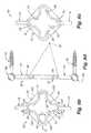
- FIG. 1is a side perspective view of two vertebra in a neutral position
- FIG. 2is a side perspective view of the two vertebra shown in FIG. 1 in a condition of flexion;
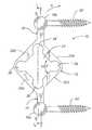
- FIG. 3 ais a side elevation view of a first embodiment of a dynamic fixation device used in conjunction with pedicle screws;
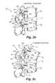
- FIG. 3 bis a side perspective view of the device shown in FIG. 3 a attached to two vertebra in a neutral position;
- FIG. 3 cis a side perspective view of the device shown in FIG. 3 a attached to two vertebra in a flexed position;
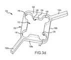
- FIG. 3 dis a side perspective view of an embodiment of a dynamic fixation device
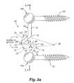
- FIG. 3 eis a view of the device shown in FIG. 3 d along with pedicle screws;
- FIG. 3 fis a detail view of a portion of FIG. 3 e;
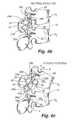
- FIG. 4 ais a side elevation view of a separate embodiment of a dynamic fixation device used in conjunction with pedicle screws;
- FIG. 4 bis a side perspective view of the device shown in FIG. 4 a attached to two vertebra in a neutral position;
- FIG. 4 cis a side perspective view of the device shown in FIG. 4 a attached to two vertebra in a flexed position;
- FIG. 5 ais a side elevation view of a modification of the dynamic fixation device shown in FIG. 4 a used in conjunction with pedicle screws;
- FIG. 6 ais a front perspective view of a separate embodiment of a dynamic fixation device
- FIG. 6 bis a front elevation view of the device shown in FIG. 6 a;
- FIG. 6 cis a rear elevation view of the device shown in FIG. 6 a;
- FIG. 6 dis a side elevation view of the device shown in FIG. 6 a;
- FIG. 6 eis a side perspective view of the device shown in FIG. 6 a attached to two vertebra in a neutral position;
- FIG. 6 fis a side perspective view of the device shown in FIG. 6 a attached to two vertebra in a flexed position;
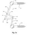
- FIG. 7 ais a side elevation view of a separate embodiment of a dynamic fixation device used in conjunction with pedicle screws;
- FIG. 7 bis a side perspective view of the device shown in FIG. 7 a attached to two vertebra in a neutral position;
- FIG. 7 cis a side perspective view of the device shown in FIG. 7 a attached to two vertebra in a flexed position;
- FIG. 8 ais a side elevation view of a separate embodiment of a dynamic fixation device used in conjunction with pedicle screws;
- FIG. 9 ais a side elevation view of a separate embodiment of a dynamic fixation device used in conjunction with pedicle screws;
- FIG. 9 bis a side perspective view of the device shown in FIG. 9 a attached to two vertebra in a neutral position;
- FIG. 9 cis a side perspective view of the device shown in FIG. 9 a attached to two vertebra in a flexed position;
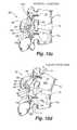
- FIG. 10 ais a side elevation view of a separate embodiment of a dynamic fixation device used in conjunction with pedicle screws;
- FIG. 10 bis a side elevation view of a portion of the device shown in FIG. 10 a;
- FIG. 10 cis a side perspective view of the device shown in FIG. 10 a attached to two vertebra in a neutral position;
- FIG. 10 dis a side perspective view of the device shown in FIG. 10 a attached to two vertebra in a flexed position.
- flexioninvolves a combination of anterior sagittal rotation and a small amplitude anterior translation.
- the various embodiments of the present inventionallow for controlled rotation while limiting translation within an acceptable, normal physiological range.
- the dynamic fixation device 10includes a geometric shape 12 connected to a first rod end 14 and a second rod end 16 .
- First rod end 14 and second rod end 16are preferably connected to connectors 18 a and 18 b that, in turn, are connected to pedicle screws 20 .
- Pedicle screws 20are inserted into the pedicles of vertebrae when the device is attached to the vertebrae of a patient.
- Connectors 18 a and 18 bcan be of the type that are integrally formed as part of first rod end 14 and second rod end 16 , respectively.
- one or both of the connectorscan be a separate type of connector that can be selectively positioned along the length of first rod end 14 or second rod end 16 , respectively, such that first rod end 14 and second rod end 16 are adjustable (e.g., slidably) within the connectors prior to tightening the connectors to fixedly interconnect the device 10 to the pedicle screws 20 .
- dynamic fixation device 10is shown in a neutral position.
- the dynamic fixation device 10includes a geometric shape 12 between first rod end 14 and second rod end 16 .
- dynamic fixation device 10includes a substantially rectangular or substantially diamond-shaped geometric shape 12 that has four arms 22 a , 22 b , 22 c and 22 d .
- opening 24can be formed of and/or covered by a flexible or an elastic-type webbing material (not shown).
- the centerline of geometric shape 12is offset relative to the longitudinal axis of dynamic fixation device 10 . More particularly, as shown in FIG. 3 a , dynamic fixation device 10 has a longitudinal axis L-L that passes through the centerline of first rod end 14 and second rod end 16 . However, the centerline CL-CL of geometric shape 12 is offset posteriorly to the longitudinal axis L-L of dynamic fixation device 10 . This offset provides a preference for the dynamic fixation device 10 to bend in flexion, but resist bending in extension.
- the arms 22 a , 22 b , 22 c , and 22 d of geometric shape 12are situated desired angles (e.g., at approximately 90 degree angles) relative to each other when device 10 is in the neutral position.
- arm 22 ais situated at an angle of about 90 degrees relative to arm 22 b and arm 22 d .
- arm 22 cis situated at an angle of about 90 degrees relative to arm 22 b and arm 22 d .
- the convergence segments 26 between the armsincludes reduced dimensions. More particularly, the dimensions of arms 22 a and 22 b are smaller in the vicinity where arm 22 a joins arm 22 b . Likewise, the dimension of arms 22 b and 22 c are also smaller in the vicinity where arm 22 b joins arm 22 c . This is also the case for the convergence segments between arms 22 c and 22 d , and between arms 22 d and 22 a .
- the decreased dimensions of the arms 22 a , 22 b , 22 c and 22 d at the convergence segments 26allow additional flexibility between the arms. As shown in FIG. 3 a , the convergence segments 26 include partially circular corners between the arms.
- dynamic fixation device 10preferably includes narrowing or thinning of the arms in the vicinity of the convergence segments 26 . It is to be further noted that convergence segments 26 serve as elastomeric hinges for geometric shape 12 .
- first rod end 14is shown to remain essentially immobile.
- Second rod end 16moves between a neutral or first position 28 , as shown in FIG. 3 b , and a flexed or second position 30 , as shown in FIG. 3 c .
- dynamic fixation device 10elongates and it also rotates about an effective pivot point 32 .
- the geometric shape 12provides an effective pivot point 32 that is forward or anterior of the longitudinal axis L-L of first rod end 14 and second rod end 16 .
- dynamic fixation device 10experiences deformation, whereby it bends and it elongates.
- first rod end 14 and second rod end 16 of dynamic fixation device 10are preferably interconnected using connectors 18 a and 18 b to pedicle screws 20 that are inserted into vertebrae V 1 and V 2 of the spine.
- connectors 18 a and 18 bto pedicle screws 20 that are inserted into vertebrae V 1 and V 2 of the spine.
- each vertebraexhibits an arcuate motion in relation to the vertebra below. The center of the arc lies below the moving vertebra.
- Dynamic fixation device 10provides a device for allowing movement of the upper vertebra V 1 to a flexed or second position 30 , with a forwardly or anteriorly projected pivot location 32 , as compared to the location of the longitudinal axis L-L of the device 10 when it is in the neutral position.
- the geometric shape 12can be subdivided into four smaller rectangles (not shown) as opposed to one large rectangle. This modification of using four smaller rectangles to form a geometric shape still acts as a larger rectangle in terms of its effective pivot point.
- geometric shape 12can take the form of a rhomboid (not shown). In this modification, an effective pivot point would be projected forward (or anterior) some distance of the dynamic fixation device. Accordingly, depending upon its construction, the geometric shape 12 allows the pivot point to extend beyond the limits of the device. When the dynamic fixation device 10 is implanted posterior the spinal vertebrae, the device nonetheless allows for a rotation point substantially anterior the device.
- the present inventionallows an effective pivot point 32 to be created that substantially corresponds to the natural pivot point of the patient's spine.
- a dynamic fixation device 104includes geometric shape 108 with an interior hollow region 112 .
- Interior hollow region 112preferably includes four partially circular corners 116 .
- partially circular corners 116may be of a different shape, such as partially triangular.
- Geometric shape 108expands and deforms to allow controlled movement of the spine.
- the interior hollow region 112preferably includes transverse straight sidewalls 120 . That is, the interior sidewalls 120 have an interior surface 124 that is at an angle of 90 degrees relative to the planar surface 128 of geometric shape 108 .
- interior sidewalls 120are situated at 90 degree angles relative to each other, as labeled in FIG. 3 e .
- the geometric shape 108Upon deformation due to flexion of the spine, the geometric shape 108 deforms.
- the 90 degree angles between interior sidewalls 120will change, such that geometric shape 108 expands and becomes a parallelogram.
- each rod arm 132 a,bis situated at an angle of about 120 degrees from exterior sides 136 a,b of the geometric shape 108 .
- each rod arm 132 a,bmay be situated at angles different than 120 degrees, wherein the chosen angles combine to provide a different projected pivot point in the plane of the geometric shape 108 upon flexion of the spine.
- rod arm 132 amay be situated at an angle of 120 degrees from exterior side 136 a
- rod arm 132 bmay be situated at an angle of 110 degrees from exterior side 136 b.
- first arm 132 a and second arm 132 b of dynamic fixation device 104are preferably interconnected to connectors 18 a and 18 b and then to pedicle screws 20 that are inserted into vertebrae of the spine (not shown).
- each vertebraexhibits an arcuate motion in relation to the vertebra below.
- the center of the arclies below the moving vertebra.
- Dynamic fixation device 104provides a device for allowing movement of the vertebra, with a forwardly or anteriorly projected pivot location that models and substantially aligns with the actual vertebra's pivot point of rotation. Accordingly, dynamic fixation device 104 provides a bendable rod for fusion that mimics the movement of the vertebrae of the spine.
- FIG. 4 aa side elevation view of a separate embodiment of a dynamic fixation device 34 is shown.
- the dynamic fixation device 34 of FIG. 4 autilizes two adjacent but connected substantially geometric shapes 36 a and 36 b .
- Substantially geometric shapes 36 a and 36 bact as two accordion shapes that expand and flexibly bend forward as dynamic fixation device 34 is elongated and rotated during bending of the spine.
- Arrow Adepicts the general direction of motion of second rod end 16 during rotation and elongation of the dynamic fixation device 34 .
- substantially geometric shapes 36 a and 36 binclude a plurality of arms.
- Substantially geometric shape 36 aincludes an anterior arm 38 a and a posterior arm 40 a .
- substantially geometric shape 36 bincludes an anterior arm 38 b and a posterior arm 40 b .
- anterior arm 38 ainterconnects to posterior arm 40 b by crossing arm 42 .
- anterior arm 38 binterconnects to posterior arm 40 a by crossing arm 44 .
- crossing arm 42can be hingedly connected to crossing arm 44 using a pin 46 positioned along crossing arm 42 and crossing arm 44 .
- opening 24 aexists between crossing arm 42 , anterior arm 38 a and posterior arm 40 a of substantially geometric shape 36 a
- another opening 24 bexists between crossing arm 44 , anterior arm 38 b and posterior arm 40 b
- openings 24 a and 24 bcan be formed of a flexible or an elastic-type webbing material (not shown).
- FIGS. 4 b and 4 cshow dynamic fixation device 34 in its neutral and flexed positions, respectively.
- the effect of the substantially geometric shapes 36 a and 36 bis to produce an anteriorly projected effective pivot point 32 that substantially matches the rotational point of the vertebrae to which it is attached.
- the device of FIGS. 4 a - 4 csubstantially limits translational displacement of the vertebrae to which it is attached, while still allowing some amount of flexion.
- the bending occurring with flexionis equal to the angle change between anterior arm 38 a and anterior arm 38 b as the construct elongates.
- there is a rigid connection between first rod end 14 and anterior arm 38 aas well as a rigid connection between second rod arm 16 and anterior arm 38 b.
- the centerline of substantially geometric shapes 36 a and 36 bis offset posteriorly relative to the longitudinal axis of dynamic fixation device 34 . More particularly, as shown in FIG. 4 a , dynamic fixation device 34 has a longitudinal axis L-L that passes through the centerline of first rod end 14 and second rod end 16 . However, the centerline CL-CL of substantially geometric shape 36 a and 36 b is offset posteriorly to the longitudinal axis L-L of dynamic fixation device 34 . This offset provides a natural fixation for the first rod end 14 to be a continuation of anterior arm 38 a , and for second rod end 16 to be a continuation of anterior arm 38 b.
- more than two substantially geometric shapesmay be incorporated into a dynamic fixation device 34 ′.
- the dynamic fixation device 34 having substantially geometric shapes 36 a and 36 bmay be modified to include a third, fourth, fifth, or any number of additional substantially geometric shapes.
- substantially geometric shapes 36 a and 36 b of the device shown in FIG. 4 aillustrate two substantially diamond shaped features, respectively.
- a third substantially diamond shape 36 cmay be added to geometric shape 36 a and 36 b .
- Optional pins 46may be used between the various substantially geometric shapes.
- substantially geometric shapesmay differ in size and/or overall shaped configuration, which may be desirous depending upon the number used. For example, where three substantially geometric shapes 36 a , 36 b and 36 c are used, as in dynamic fixation device 34 ′, the overall size of each geometric shape is preferably smaller than the two substantially geometric shapes 36 a and 36 b illustrated in dynamic fixation device 34 , as shown in FIG. 4 a .
- The, addition of added substantially geometric shapesprojects the pivot pint 32 proportionally forward for the number of substantially geometric shapes used.
- a dynamic fixation device 50includes geometric shape 12 with an interior hollow region 24 , wherein device 50 bends in a direction transverse to the planar surface 52 of geometric shape 12 .
- the interior hollow region 24preferably includes sloped interior surface 54 . That is, the interior sidewalls 56 have an interior surface 54 that is at an angle ⁇ . with the planar surface 52 of geometric shape 12 .
- Angle ⁇ of interior surface 54can be one constant value, or it can vary within the device. By way of a non-limiting example, ⁇ can be 60 degrees at the top of device 50 , and vary to about 90 degrees at the bottom of device 50 .
- interior hollow region 24preferably includes four partially circular corners or convergence segments 26 . Attached to two opposing partially circular corners or convergence segments 26 are first rod end 14 and second rod end 16 . Each rod end 14 and 16 is situated at an angle of about 135 degrees from each adjacent side of the geometric shape 12 . However, in an alternate aspect of this embodiment, the rod ends 14 and 16 may be situated at different angles relative to the arms of the geometric shape 12 . As with device 10 , partially circular corners or convergence segments 26 may be of a different shape, such as partially triangular. Equivalently, a mechanical hinge rather than an elastomeric hinge may be incorporated at convergence segments 26 .
- pedicle screws 20are orientated perpendicular to the planar surface 52 of geometric shape 12 .
- Connectors 18 a and 18 bare used to attach the pedicle screws 20 to first and second rod ends 14 and 16 of dynamic fixation device 50 .
- the connectors 18 a , 18 bmay be formed as an integral part of dynamic fixation device 50 , or the connectors 18 a, 18 b may be a separate device, as is known to those knowledgeable in the art.
- the dynamic fixation device 50expands as it rotates and/or bends when attached to two vertebra that undergo flexion.
- Dynamic fixation device 58includes four substantially straight and rigid arm segments. These consist of lower arm 60 a , first middle arm 60 b , second middle arm 60 c , and upper arm 60 d . Lower arm 60 a and upper arm 60 d connect to connectors 18 a and 18 b, respectively, which are then connected to pedicle screws 20 . Using pins 46 , lower arm 60 a is hingedly connected to one end of middle arms 60 b and 60 c . Upper arm 60 d is hingedly connected using pins 46 to the opposite end of middle arms 60 b and 60 c .
- an opening 24that is a quadrilateral shape.
- upper arm 60 dmoves upward and forward, thereby forcing middle arms 60 b and 60 c to rotate downward.
- the hinged connection of middle arms 60 b and 60 c to upper arm 60 dallows it to move forward, while the connection of middle arms 60 b and 60 c to lower arm 60 a prevents excessive translation or over-rotation.
- Dynamic fixation device 58allows for the upper vertebra to move up and forward, yet resists excessive translation of the vertebrae to which it is attached.
- the dynamic fixation device 62 shown in FIG. 8 ais a dynamic fixation device that features an anterior-posterior segment 64 .
- the dynamic fixation device 62includes a first rod end 14 having a rod arm 65 that extends at an angle a toward an anterior-posterior segment 64 .
- Angle ⁇is fixed in relation to pedicle screw 20 by the rigid connection between rod arm 65 and lower pedicle screw 20 .
- rod arm 73is fixed by a rigid connection to the upper pedicle screw 20 .
- Rod arm 65 of first rod end 14is connected to anterior-posterior segment 64 at bend 66 .
- bend 66 forming the connection between rod arm 65 and anterior-posterior segment 64can be a continuous structural piece such that rod arm 65 and anterior-posterior segment 64 are essentially a contiguous solid piece including bend 66 .
- bend 66may be a hinged connection with a pin that interconnects rod arm 65 to anterior-posterior segment 64 .
- Anterior-posterior segment 64is separated from rod arm 65 by angle ⁇ .
- anterior-posterior segment 64extends posteriorly to bend 68 .
- Middle rod segment 70extends from bend 68 at the posterior end of anterior-posterior segment 64 to bend 72 that forms the connection to rod arm 73 of second rod end 16 .
- Bend 72forms the intersection and the connection between middle rod segment 70 and rod arm 73 .
- Bend 72can be a continuous structural piece such that middle rod segment 70 and rod arm 73 are essentially a contiguous solid piece including bend 72 , or bend 72 can be a connection that interconnects middle rod segment 70 and rod arm 73 .
- the middle rod segment 70is separated from the anterior-posterior segment 64 by angle ⁇ .
- First rod end 14 and second rod end 16preferably are interconnected to pedicle screws 20 using connectors 18 a and 18 b , respectively.
- Connectors 18 a and 18 bcan be formed as an integral part of the end of dynamic fixation device 62 , or they can be separate devices, as is known to those knowledgeable in the art.
- dynamic fixation device 62also has a longitudinal axis L-L that is defined by the center of connectors 18 a and 18 b .
- Rod arm 65generally lies anterior of longitudinal axis L-L
- middle rod segment 70generally lies posterior of longitudinal axis L-L
- anterior-posterior segment 64having portions both on the anterior and posterior sides of longitudinal axis L-L.
- bend 68preferably acts as a hinge and is able to move down if the vertebrae to which the dynamic fixation device 62 is attached is placed in compression.
- bend 68can move up to accommodate flexion of the vertebrae.
- This motion of bend 68 and the anterior-posterior segment 64closely approximates the normal arc of motion of human vertebra.
- bend 68moves down along a lower arc path 74 .
- Lower arc path 74is caused when dynamic fixation device 62 is placed in compression and anterior-posterior segment 64 moves toward rod arm 65 , thereby decreasing the angle ⁇ .
- angle ⁇may decrease up to 30 degrees as bend 68 passes along lower arc path 74 .
- bend 68 of dynamic fixation device 62preferably includes a structure to allow it to act as a hinge. Accordingly, bend 68 may include a pin 75 . As illustrated in FIG. 8 a , pin 75 is shown in the neutral position. However, in the compressed position, pin 75 ′ is shown in its lower position. When the vertebrae undergo flexion, bend 68 moves up along an upper arc path 76 . Upper arc path 76 is caused when dynamic fixation device 62 elongates and anterior-posterior segment 64 moves upward, thereby increasing the angle ⁇ . In a typical human implant, angle ⁇ may increase up to 30 degrees as bend 68 passes along upper arc path 76 .
- the neutral position for anterior-posterior segment 64will be slanted downward from horizontal, with bend 68 positioned lower than bend 66 .
- angle ⁇would have a lesser amount of allowable compression over flexion extension.
- pin 75 ′′is shown in its upper position. In compression, angle ⁇ will decrease, and when the dynamic fixation device elongates during flexion, angle ⁇ will increase.
- the various embodiments of the present inventionallows a slight amount of translational motion of the vertebrae, but the amount of translational motion allowed is within the physiological limits of normal motion of the human vertebrae.
- the vertebraewill undergo a slight amount of translational movement, as is evidenced by the position of pin 75 ′ and 75 ′′, which are moved slightly anterior or forward from the neutral position.
- Dynamic fixation device 78includes three substantially straight arm segments. These consist of lower arm 80 a , first middle arm 80 b , and upper arm 80 c . Lower arm 80 a and upper arm 80 c connect to connectors 18 a and 18 b , respectively, which are then connected to pedicle screws 20 . Using a pin 46 , lower arm 80 a is hingedly connected to one end of middle arm 80 b . The opposite end of middle arm 80 b is hingedly connected (e.g., by a pin 46 ) to upper arm 80 c .
- middle arm 80 bin the present embodiment acts as an anterior-posterior segment that allows a range of motion in flexion, yet prevents the vertebrae from experiencing excessive translation.
- dynamic fixation device 78allows for the upper vertebra to move up and slightly forward, yet resists excessive translation of the vertebrae to which it is attached.
- Dynamic fixation device 82includes a first rod member 84 connected to a first rod end 14 and a second rod member 86 connected to a second rod end 16 , wherein the first rod end 14 and the second rod end 16 are interconnected to pedicle screws 20 using connectors 18 a and 18 b , respectively.
- rails 90confine spring 88 on the lateral sides, and rails 90 also serve to interconnect first rod member 84 to second rod member 86 .
- the structure of dynamic fixation device 82provides for an articulated device that can also elongate, thus accommodating the natural physiologic motion of two adjacent vertebra when undergoing flexion. The structure and function of these components will be described in detail below.
- first rod member 84preferably includes a concave surface 92 along its posterior side, wherein the concave surface 92 of first rod member 84 assists in providing anterior confinement of spring 88 .
- Second rod member 86preferably includes a concave surface 94 along its anterior side, wherein the concave surface 94 of second rod member 86 assists in providing posterior confinement of spring 88 .
- rails 90interconnect the first rod member 84 to second rod member 86 .
- rails 90comprise a plate 96 with hinge pins 46 situated through both ends of the plate 96 .
- Plate 96is shown in FIG. 10 b .
- first rod member 84includes a first notch 98 for receiving a first hinge pin 46 .
- second rod member 86includes a second notch 98 receiving a second hinge pin 46 .
- Plates 96span the confinement zone 100 of spring 88 and interconnect first rod member 84 and second rod member 86 while laterally containing spring 88 between rod members 84 and 86 and preventing the spring 88 for moving outside of the confinement zone 100 .
- rails 90may be formed using a single piece. That is, the plate 96 and hinge pin 46 construction may be machined or otherwise constructed of a single piece.
- spring 88is a cylindrical shaped spring having a proper spring constant for the dynamic fixation device 82 .
- spring 88may also take the form of a resilient material, such as a properly sized silicone insert shaped, for example, as a disc or a sphere.
- second rod member 86moves up and forward.
- the spring 88rolls between the first rod member 84 and the second rod member 86 . Since the spring 88 rolls, friction between first rod member 84 and second rod member 86 is minimal.
- the ability of the spring to rollcan be modified by adjusting the shape of the spring and the shape and texture of the interior walls of the confinement zone 100 .
- the shape and surface texture of concave surfaces 92 and 94 of the first and second rod members 84 and 86 , respectively,can be modified to adjust the magnitude and ease of motion in elongation of the second rod member 86 relative to the first rod member 84 .
- the spring 88is cable of being compressed, it deforms, thereby allowing bending.
- the amount of compressionis controlled by the spring characteristics, such as the spring material type, diameter and wall thickness, as well as the shape of the confinement zone 100 and the texture of the concave surfaces 92 and 94 .
- the concave surfaces 92 and 94serve as the compression surfaces of the confinement zone 100 for spring 88 .
- the shape of the curves of the concave surfaces 92 and 94can be altered to control the degree of spring compression as the construct elongates.
- the curvature of concave surfaces 92 and 94can be flattened, thereby influencing the reaction of the spring 88 within the confinement zone 100 during flexion extension.
- dynamic fixation device 82is shown both in its neutral position and it the flexed position, respectively.
- the rails 90are dashed in FIGS. 10 c and 10 d .
- the elongated position of FIG. 10 dillustrates that spring 88 has rolled up and is also slightly compressed.
- the characteristics of the spring 88are chosen such that some desired amount of compression of the spring is allowed during flexion; however, the spring 88 is stiff enough such that unwanted amounts of translation of the vertebrae are resisted.
- Dynamic fixation device 82is allowed to elongate because second rod member 86 is hingedly attached to first rod member 84 , thereby allowing vertical motion of second rod member 86 relative to first rod member 84 .
- the structure of dynamic fixation device 82provides for an articulated device that can elongate, thus accommodating the natural physiologic motion of the spine.
- Dynamic fixation device 82has application to providing segmentally applied motion control of the spine because each motion segment designated to receive an implant can have a dynamic fixation device implant customized through its dimensions and spring constant, thereby giving the patient controlled motion within a desired normal physiologic range.
- the total length of the dynamic fixation devices 10 , 34 , 34 ′, 50 , 58 , 62 , 78 , and 82may be approximately 15 to 35 mm.
- the geometric shape portions or hinge structures of the dynamic fixation devicespreferably occupy the central region of the implant that bridges two vertebra. That is, the geometric shapes or hinge structures occupy only a portion of the implant, thereby allowing first rod end 14 and second rod end 16 to be solid rod segments that can be interconnected to a pedicle screw using a connector device. For those devices comprising a geometric shape or hinged structure, these structures will typically occupy approximately 15 to 20 mm of the total length.
- dynamic fixation deviceFor a dynamic fixation device spanning one joint, it will expand up to approximately 5 to 10 mm in length, and will rotate forward up to between 5 to 10 degrees to accommodate flexion of the spine.
- different size dynamic fixation devicesmay be used to accommodate the specific needs of each individual patient. More particularly, a relatively large dynamic fixation device may be needed for a large man, while a relatively small dynamic fixation device may be needed for a smaller patient, such as child or a petite woman. However, a limited number of sizes may provide adequate coverage for the majority of the patient population. For any given device, a potential elongation of the dynamic fixation device consistent with the desired flexion of the vetebral motion segment and associated distraction of the plane of the fixation device is anticipated.
- the dynamic fixation devicescan be used to flexibly secure a plurality of vertebra.
- the dynamic fixation devicescan be located at specific points where bending of the spine is desired, while a rigid rod may be used at other locations desired by the physician.
- rigid rod portionsmay be curved, thereby influencing the implanted location of the geometric shape hinged structures, and thus the effective pivot point.
- the structures of the present inventionare made from one or more materials that possesses the appropriate strength characteristics necessary to withstand loading from the human body when used in medical applications.
- the materialsare compatible with the human body.
- materialsinclude ceramics, plastics, metals, or carbon fiber composites. More preferably, the materials are made from titanium, a titanium alloy, or stainless steel.
- Dynamic fixation devices described hereinmay be made of a variety of materials, preferably metals or materials demonstrating resilient characteristics, and more preferably, a titanium alloy or surgical stainless steel. Since different materials have different strength and resilient properties, the type of material used will, in part, dictate the dimensions of the rod portion required to achieve a certain function in a specific patient.
- Devices disclosed hereincan also be made of thermal memory materials or materials that possess different elastic properties at varying temperatures.
- the subject component(s)may be heated or cooled to a desired temperature, implanted, then subsequently allowed to cool or warm to the temperature of the ambient conditions that will exist during the usage period for the subject device, namely, normal body temperature.
- the present inventionmay have application to medical devices other than spinal implants.
- the present inventioncan be used in external fixator systems.
- the dynamic fixation device of the present inventionis not limited to medical implants.
- the devicecould be used in seismic dampening applications.
- the present inventioncould be used to secure any two objects, such as in linking mechanisms, and has application to any type of mechanical device with a moving connection.
- Other applicationsby no means exhaustive, may include connecting any articulated device, such as an implement connection to a tractor. It may also be used in heretofore static type connection applications, such as attaching an antenna to a base structure.
Landscapes
- Health & Medical Sciences (AREA)
- Orthopedic Medicine & Surgery (AREA)
- Life Sciences & Earth Sciences (AREA)
- Neurology (AREA)
- Surgery (AREA)
- Heart & Thoracic Surgery (AREA)
- Engineering & Computer Science (AREA)
- Biomedical Technology (AREA)
- Nuclear Medicine, Radiotherapy & Molecular Imaging (AREA)
- Medical Informatics (AREA)
- Molecular Biology (AREA)
- Animal Behavior & Ethology (AREA)
- General Health & Medical Sciences (AREA)
- Public Health (AREA)
- Veterinary Medicine (AREA)
- Surgical Instruments (AREA)
- Prostheses (AREA)
- Diaphragms For Electromechanical Transducers (AREA)
Abstract
Description
The present application is a continuation application of U.S. patent application Ser. No. 10/435,330 filed on May 8, 2003, which claimed the benefit of: U.S. Provisional Patent Application No. 60/379,167 filed May 8, 2002 entitled “Dynamic Fusion System”; U.S. Provisional Patent Application No. 60/390,181 filed Jun. 19, 2002 entitled “Dynamic Fusion System”; and U.S. Provisional Patent Application No. 60/417,722 filed Oct. 9, 2002 entitled “Dynamic Fusion System,” all of which are incorporated herein by reference in their entireties. Cross-reference and incorporation thereof is also made to U.S. Nonprovisional patent application Ser. No. 10/406,895 filed on Apr. 4, 2003 entitled “Dynamic Fixation Device And Method of Use,” now U.S. Pat. No. 6,966,910.
This invention relates generally to securement devices and, more particularly, to a flexible rod or device along a portion thereof that is capable of flexibly securing vertebrae together.
The lumbar spine absorbs a remarkable amount of stress and motion during normal activity. For the majority of the population, the healing response of the body is able to stay ahead of the cumulative effects of injury, wear, and aging, and yet still maintain stability with reasonable function. In some cases, however, the trauma or stress exceeds the ability of the body to heal, leading to local breakdown and excessive wear, and frequently also leads to local instability. Accordingly, degenerative change with age superimposed on baseline anatomy in the lumbar spine leads to problems including instability, pain and neurologic compromise in some patients. In some cases, the local anatomy may not provide the same protection to the motion segment, thereby aggravating this breakdown. Although rehabilitation, conditioning, the limitation of stress, and time to recover are effective treatments for most patients, there is a significant failure rate with persistent pain, disability and potential neurologic deficit.
Referring now toFIGS. 1 , and2, two side views of a pair of adjacent vertebral bodies are shown.FIG. 1 illustrates two vertebra V1and V2of the spine in a neutral position. As shown inFIG. 2 , when a person leans forwards, the spine undergoes flexion. The anterior portion of the spine comprises a set of generally cylindrically shaped bones which are stacked one on top of the other. These portions of the vertebrae are referred to as the vertebral bodies VB1and VB2, and are each separated from the other by the intervertebral discs D. The pedicles P1and P2comprise bone bridges which couple the anterior vertebral body VB to the posterior portion of each vertebra. At each intervertebral joint or disc D, flexion involves a combination of anterior sagittal rotation and a small amplitude anterior translation.
The intervertebral joint is a complex structure comprising an intervertebral disc anteriorly, and paired zygapophyseal joints posteriorly. The disc functions as an elastic support and connection between the vertebra, and allows for flexion and extension of the spine, as well as limited rotation and translation. The zygapophyseal joints and associated anatomy allow for significant flexion and extension while providing constraints in translation and rotation.
The primary bending motion in the lumbar spine is flexion and extension in an anterior/posterior plane. This occurs in the range approximating 10-15 degrees of flexion and extension. In a young or normal lumbar spine, this motion occurs about an axis in the mid to posterior portion of the disc. This is associated with a distraction or subluxation of the facet joints or posterior elements of 10-15 mm. This occurs not about a pure axis, but about a neutral zone, or a centroid of rotation associated with the lumbar disc. The normal elasticity of the disc, joints and ligaments, and the degree of play or freedom associated with these joints, as well as the nature of the loads applied to the spine contribute to the size of this region of rotation. In some cases, the recurrent loads and motion on the disc and associated trauma to disc and motion segment exceed the natural rate of healing or repair of the body. In this situation, there is breakdown in the motion segment associated with loss of the normal axis of rotation. As increasing subluxation occurs with segmental motion, there is a dramatic shift in the axis of rotation with displacement occurring within the disc space or frequently to some point outside of the disc. Therefore, in the situation of a failing motion segment, there is breakdown in the centroid of rotation with associated translation of the vertebral segments. This translation is allowed by both breakdown occurring in the disc and instability associated with both wear and degeneration of the zygapophyseal joints. The underlying anatomy of the motion segment and joints allows for significantly greater stress on the disc and contributes to degeneration both in the disc and joints.
Traditionally, surgical treatment has been directed at treating neural compromise, or if the pain, instability, or risk of instability is considered sufficient, a segmental fusion has been considered. More recently, stabilization procedures have been tried over the past several years including artificial discs and ligaments and elastomeric constructs to protect the spine. Arthroplasty techniques to maximize function and reduce the dynamic effects on adjacent segments are a more recent approach with less follow-up as to long-term results. A challenge in designing such a system is constraining motion in a normal physiologic range.
Spinal fusion surgery is a method of fusing at least two mobile segments of the spine to knit them together as one unit and eliminate motion between the segments. Current spinal fixation systems offer several drawbacks. Rigid fusion constructs do not allow relative movement between the vertebrae that are fused using a construct comprising a pedicle screw, connector mechanism, and rigid rod. Furthermore, rigid implants are known to create significant amounts of stress on the components of the construct, including the pedicle screws and the rod, as well as the bone structure itself. These stresses may even cause the rigid rod to break. In addition, the stresses transferred to the pedicle screws may cause the screws to loosen or even dislodge from the vertebrae, thereby causing additional bone damage.
Artificial discs may replace a failing disc and approximate a normal centroid or axis of rotation; however, placement of such a device is technically demanding and replaces the normal disc with a mechanical replacement with uncertain long-term results. The artificial disc will be subject to wear without the healing potential of the body to heal itself.
It is also desirable with some patients to have a spinal implant system that allows the vertebral column to settle naturally under the weight of the human body. Human bone heals more readily under some pressure. In a rigid spinal implant system, the patient's spinal column may be unnaturally held apart by the structure of the implant. It is possible that this stretching of the vertebrae, in relation to one another, results in delayed or incomplete healing of the bone.
Posterior devices placed with pedicle fixation may provide some stabilization, however, the natural motion of such devices does not necessarily act to mimic normal physiology. In a healthy lumbar spine the axis of rotation or neutral area for motion is situated near the inferior posterior third of the lumbar disc. A desirable artificial system would closely approximate physiologic motion. However, to date, posterior systems have failed to address these concerns.
Several existing patents disclose fusion devices. For example, U.S. Pat. No. 5,415,661 discloses a device that includes a curvilinear rod such that the implant supposedly restores normal biomechanical function to the vertebrae of the spine receiving the implant. However, the '661 patent does not disclose a device having structure other than a curvilinear shape that has a radius of curvature of between 0 to 180 degrees. In addition, the '661 patent does not disclose the concept of providing an anteriorly projected pivot point that models the natural articulation of the subject vertebrae by using a structure that provides a virtual rotation zone substantially identical to the rotation zone provided by the patient's vertebrae. In addition, as seen inFIG. 3 of the '661 patent, the device disclosed in the '661 patent utilizes a body4 having acentral section 10 having an anteriorly oriented position relative to its ends6a,6b.
U.S. Pat. No. 6,293,949 also discloses a spinal stabilization device intended for use along the cervical vertebrae, and intended to be installed along the anterior side of the vertebrae.
U.S. Pat. No. 6,440,169 discloses a device that attaches to the spinous processes of two vertebrae and has a leaf spring that allows the device to compress and then recover spontaneously after the stress has ceased. However, the '169 patent does not address a construct that includes an anteriorly projected pivot point that allows the vertebrae to articulate when the spine undergoes flexion.
In view of the above, there is a long felt but unsolved need for a method and system that avoids the above-mentioned deficiencies of the prior art and that provides an effective system that is relatively simple to employ and requires minimal displacement or removal of bodily tissue.
The present invention provides a device that can be implanted and that provides for a specified amount of forward bending motion, thereby allowing anterior sagittal rotation between the vertebrae that receive the implant. Reference is hereby made for the incorporation of the conventional descriptive terms of motion and other content presented inClinical Anatomy of the Lumbar Spine and Sacrumby Nikolai Bogduk, third edition, published by Churchill Livingstone, 1999. Although anterior sagittal rotation or flexion between vertebrae is normal, significant anterior sagittal translation or sliding motion between vertebrae is not. Thus, by allowing some amount of rotational motion while protecting against translation, the patient's condition or injury can be protected, thus promoting the healing process, while subsequently providing some ability to rotate one vertebra relative to an adjacent vertebra, thereby allowing for improved spinal motion following surgery and recovery. Accordingly, as described herein, various implants, including a number of rod configurations having flexible portions are presented that provide a device having the ability to elongate and bend. Thus, it is a first aspect of the present invention to provide a device that elongates, and a second aspect of the present invention to provide a device that bends. More particularly, the present invention is a dynamic fixation device that includes a flexible rod portion, wherein the flexible rod portion can include a geometric shape and/or a hinge portion. These dynamic fixation devices are constructed of a material of an appropriate size, geometry, and having mechanical properties such that they bend, thus allowing the vertebrae associated with the implant to rotate relative to one another, similar to the movement of a natural spine.
A dynamic fixation device is a quasi-flexible, semi-rigid fixation construct that allows some measure of motion between the vertebrae attached to the dynamic fixation device. Dynamic fixation of the lumbar spine provides means of protecting lumbar structures and allows for healing without proceeding to a lumbar arthrodesis. The constraints on such a system are in some ways different than for a rigid or near rigid construct, such as that used for fusion.
At the present time, pedicle fixation is an accepted method of fixing to the spine. In the situation of a lumbar fusion, a relatively rigid construct is appropriate to stabilize the spine and allow healing of the bony structures. In the situation of providing protection to the lumbar structures, a flexible system is appropriate to limit but not stop the motion of lumbar elements. The flexible elements in such a system need to accomplish several objectives. The primary objective is to allow physiologic motion of the spine, while protecting against excessive or non-physiologic movement. A secondary consideration is to protect the pedicle fixation from undue stress that could loosen the fixation at its bony interface.
The normal instantaneous axis of rotation of the lumbar spine occurs typically near the lower posterior third of the disc. Conventional pedicle fixation of the spine typically places the fixation rod or plate at the dorsal aspect of the apophyseal joint or posterior to the joint. Therefore, it is appropriate to consider a construct that effectively shifts this rotation point anteriorly toward the physiologic axis.
A group of geometries exist, which if applied to a posterior device, will constrain the subluxation of the segment and maintain the rotation in or close to the normal zone or axis of rotation. The indication for use is to constrain the stresses and motion within a range which will allow the body's normal healing response to maintain adequate competence in the motion segment to avoid development of instability or neurologic deficit and minimize pain or arthritis. The important features allow for maintenance of physiologic motion without the abnormal subluxation or translation that are associated with a degenerating disc and contribute to further degeneration. Thus, it is a separate aspect of the invention to provide a construct that limits excessive subluxation or translation.
Although the motion is complex related to the range of stresses which may be applied, it is nonetheless possible to provide a device so that while in compression, movement is axial or accompanied by slight dorsal translation, and that while in flexion allows both separation of posterior elements and slight ventral translation allowing rotation about the posterior portion of the disc.
Accordingly, it is an aspect of the present invention to provide a device that allows for some limited motion, thereby decreasing the stresses placed on the various component parts of the implant, as well as the affected vertebrae. It is a further aspect of the present invention to provide a device whose motion is designed to model the bending motion of the spine. Several separate embodiments of the present invention accomplish such tasks.
It is a separate aspect of the present invention to provide a construct that geometrically accommodates the human spinal anatomy, while providing a structural member that provides an anteriorly projected zone of rotation.
In a first embodiment, an implantable elastomeric material may be used, or a surgically implantable alloy can be used that includes a geometric shape having a plurality of arms (e.g., four arms) with an interior open region between the arms. In one example of this embodiment, the geometric shape is rectangular, such that the arms of the geometric shape are situated at 90 degree angles relative to each other. Upon deformation due to flexion of the spine, the geometric shape deforms, and the 90 degree angles between the arms change such that the geometric shape expands and becomes a parallelogram. In a separate aspect of the invention, the convergence segments of the arms include partially circular corners. Alternatively, the partially circular corners may be of a different shape, such as partially triangular. In a separate aspect of this embodiment, the inside surface of the interior sidewalls of the arms of the geometric shape have an interior surface that is at an angle of 90 degrees relative to a planar surface of the geometric shape. Attached to the exterior of the geometric shape near two opposing corners are two rod arms. The rod arms allow the device to be connected to connectors, which interconnect the device to pedicle screws. In a separate aspect of this embodiment, each rod arm may be situated at different angles and locations along the geometric shape, thereby influencing the location of the projected pivot point in the plane of the geometric shape upon flexion of the spine.
In yet a separate embodiment, a dynamic fixation device utilizes at least two adjacent geometric shapes that act in an accordion manner; however, this embodiment serves to project the effective pivot point anterior relative to the device. Therefore, the projected pivot point mimics the natural rotational axis of the vertebrae to which the device is attached. In a modification of this embodiment, more than two adjacent geometric shapes are combined to form the flexible portion of the device. One aspect of this embodiment and its modification is that smaller geometric shapes may be used with the addition of more geometric shapes. Consequently, a smaller profile dynamic fixation device can be provided, while at the same time having an effective pivot point that is projected anteriorly a sufficient distance to mimic the natural rotational axis of the vertebrae to which the device is attached.
In yet a separate embodiment, a dynamic fixation device is provided that includes a modified geometric shape that serves as the flexible portion of the device. The modified geometric shape incorporates an opening or void space that allows the device to elongate and deform to accommodate flexion of the spine.
In a yet a separate embodiment of the invention, the dynamic fusion device includes a geometric shape with an interior hollow region, preferably having sloped interior sidewalls. This feature allows the device to bend in a direction transverse to the plane of the geometric shape. The angle of the interior sidewalls can vary depending upon the desired amount of projection of the pivot point, which acts as a virtual axis of rotation for the device.
While the dynamic fixation devices described herein act to naturally control the axis or region of rotation within the device, it is also advantageous to consider the disc as part of the construct. If the disc is assumed to be competent as regards axial loads as opposed to translational loads, this competence can be used to control the disc height and concomitantly, the anterior portion of the implant and vertebral construct. Thus, in yet a separate embodiment, this allows a posterior construct having a rotatable anterior-posterior segment to effectively control translation within a specific range of motion of the segmental construct. Although there is a slight translation allowed, this is well within the natural region of rotation. This embodiment preferably includes a hinged portion having pin. If anterior-posterior segment or hinged arm is considered to be an elastomeric segment, its function depends on the translational forces being less than required to cause buckling of this segment. Controlling the shape of cross-section of this segment can allow forward bending of the spine while still maintaining competence in compression in the range of forces encountered in the implanted situation.
For the above described devices, first and second rod arms are attached to either end of the flexible construct, with the other end of the rod arms attached to connectors, which in turn are connected to pedicle screws that are inserted into vertebrae of the spine. During flexion and extension each vertebra exhibits an arcuate motion in relation to the vertebra below. The center of the arc lies below the moving vertebra. The dynamic fusion device provides a device for allowing movement of the vertebrae, with a forwardly or anteriorly projected pivot location that models and substantially aligns with the actual pivot point of rotation for the vertebrae to which the device is attached. Accordingly, the dynamic fusion device of the present invention provides a bendable rod for fusion that mimics the movement of the vertebrae of the spine.
The dynamic portions of the various embodiments of the present invention lengthen as they are elongated and shorten as they compressed. This characteristic allows the devices to be implanted in the spine with a pedicle screw system, and while the actual construct is positioned well dorsal in the spine, it allows the spine to function as though there were a flexible construct in the anterior column of the spine.
In use, a problematic spinal disc is initially identified by a physician. During surgery, an incision is made through the skin and muscle overlying the implant location of the spine. Then a first pedicle screw is inserted into a first vertebra and a second pedicle screw is inserted into a second vertebra. The surgeon then attaches the dynamic fixation device to the pedicle screws using either an adjustable connector or an end connector that is integrally formed as a part of the dynamic fixation device.
Various embodiments have been described in this summary of the invention but such embodiments are by no means to be deemed limiting to the “present invention” and the detailed description, the figures and the claims should be referred to in there totality to appreciate the true scope and breath of the present invention. Moreover, while much of the above discussion has focused on devices and particular configurations, various aspects of the present invention relate to surgical methods, methods of making such devices and methods of use which are also to be understood as being part of the present invention.
Additional advantages of the present invention will become readily apparent from the following discussion, particularly when taken together with the accompanying drawings.
The above listed drawings are not necessarily to scale.
While the present invention will be described more fully hereinafter with reference to the accompanying drawings in which particular embodiments and methods of implantation are shown, it is to be understood at the outset that persons skilled in the art may modify the invention herein described while achieving the functions and results of this invention. Accordingly, the descriptions which follow are to be understood as illustrative and exemplary of specific structures, aspects and features within the broad scope of the present invention and not as limiting of such broad scope.
As noted above, at each intervertebral joint or disc D, flexion involves a combination of anterior sagittal rotation and a small amplitude anterior translation. The various embodiments of the present invention allow for controlled rotation while limiting translation within an acceptable, normal physiological range.
Referring now toFIG. 3 a, a side elevation view of a first embodiment of adynamic fixation device 10 is illustrated. Thedynamic fixation device 10 includes ageometric shape 12 connected to afirst rod end 14 and asecond rod end 16.First rod end 14 andsecond rod end 16 are preferably connected toconnectors Connectors first rod end 14 andsecond rod end 16, respectively. Alternately, one or both of the connectors can be a separate type of connector that can be selectively positioned along the length offirst rod end 14 orsecond rod end 16, respectively, such thatfirst rod end 14 andsecond rod end 16 are adjustable (e.g., slidably) within the connectors prior to tightening the connectors to fixedly interconnect thedevice 10 to the pedicle screws20.
Still referring toFIG. 3 a,dynamic fixation device 10 is shown in a neutral position. As noted, thedynamic fixation device 10 includes ageometric shape 12 betweenfirst rod end 14 andsecond rod end 16. More specifically, in one embodimentdynamic fixation device 10 includes a substantially rectangular or substantially diamond-shapedgeometric shape 12 that has fourarms arms opening 24. In lieu of an open space, opening24 can be formed of and/or covered by a flexible or an elastic-type webbing material (not shown).
In a separate aspectdynamic fixation device 10, the centerline ofgeometric shape 12 is offset relative to the longitudinal axis ofdynamic fixation device 10. More particularly, as shown inFIG. 3 a,dynamic fixation device 10 has a longitudinal axis L-L that passes through the centerline offirst rod end 14 andsecond rod end 16. However, the centerline CL-CL ofgeometric shape 12 is offset posteriorly to the longitudinal axis L-L ofdynamic fixation device 10. This offset provides a preference for thedynamic fixation device 10 to bend in flexion, but resist bending in extension.
It is an aspect of this embodiment that thearms geometric shape 12 are situated desired angles (e.g., at approximately 90 degree angles) relative to each other whendevice 10 is in the neutral position. For example,arm 22ais situated at an angle of about 90 degrees relative toarm 22bandarm 22d. Likewise,arm 22cis situated at an angle of about 90 degrees relative toarm 22bandarm 22d. Upon deformation ofgeometric shape 12 due to flexion of the spine,geometric shape 12 deforms and the angles between the arms will change.
Still referring toFIG. 3 a, in yet a separate aspect ofdynamic fixation device 10 theconvergence segments 26 between the arms includes reduced dimensions. More particularly, the dimensions ofarms arm 22ajoinsarm 22b. Likewise, the dimension ofarms arm 22bjoinsarm 22c. This is also the case for the convergence segments betweenarms arms arms convergence segments 26 allow additional flexibility between the arms. As shown inFIG. 3 a, theconvergence segments 26 include partially circular corners between the arms. Alternatively, the partially circular corners may be of a different shape, such as partially triangular (not shown). Thus,dynamic fixation device 10 preferably includes narrowing or thinning of the arms in the vicinity of theconvergence segments 26. It is to be further noted thatconvergence segments 26 serve as elastomeric hinges forgeometric shape 12.
As shown in the example illustrated inFIGS. 3 band3c,first rod end 14 is shown to remain essentially immobile.Second rod end 16 moves between a neutral orfirst position 28, as shown inFIG. 3 b, and a flexed orsecond position 30, as shown inFIG. 3 c. In moving betweenfirst position 28 andsecond position 30dynamic fixation device 10 elongates and it also rotates about aneffective pivot point 32. Thegeometric shape 12 provides aneffective pivot point 32 that is forward or anterior of the longitudinal axis L-L offirst rod end 14 andsecond rod end 16. During movement betweenfirst position 28 andsecond position 30,dynamic fixation device 10 experiences deformation, whereby it bends and it elongates.
In use, a surgeon first makes an incision and then inserts pedicle screws20. Subsequently,first rod end 14 andsecond rod end 16 ofdynamic fixation device 10 are preferably interconnected usingconnectors pedicle screws 20 that are inserted into vertebrae V1and V2of the spine. During flexion and extension, each vertebra exhibits an arcuate motion in relation to the vertebra below. The center of the arc lies below the moving vertebra.Dynamic fixation device 10 provides a device for allowing movement of the upper vertebra V1to a flexed orsecond position 30, with a forwardly or anteriorly projectedpivot location 32, as compared to the location of the longitudinal axis L-L of thedevice 10 when it is in the neutral position.
In a modification of the embodiment shown inFIG. 3 a, thegeometric shape 12 can be subdivided into four smaller rectangles (not shown) as opposed to one large rectangle. This modification of using four smaller rectangles to form a geometric shape still acts as a larger rectangle in terms of its effective pivot point. In yet an alternate modification of this embodiment,geometric shape 12 can take the form of a rhomboid (not shown). In this modification, an effective pivot point would be projected forward (or anterior) some distance of the dynamic fixation device. Accordingly, depending upon its construction, thegeometric shape 12 allows the pivot point to extend beyond the limits of the device. When thedynamic fixation device 10 is implanted posterior the spinal vertebrae, the device nonetheless allows for a rotation point substantially anterior the device. Thus, depending upon the geometry of the dynamic fixation device, and more particularly, the geometry ofgeometric shape 12, the present invention allows aneffective pivot point 32 to be created that substantially corresponds to the natural pivot point of the patient's spine.
Referring now toFIGS. 3 d-3f, in a separate embodiment of the invention, adynamic fixation device 104 includesgeometric shape 108 with an interiorhollow region 112. (With the exception of angles, values shown inFIGS. 3 d-3fare proportional values giving the approximate relative size of the structural features.) Interiorhollow region 112 preferably includes four partiallycircular corners 116. Alternatively, partiallycircular corners 116 may be of a different shape, such as partially triangular.Geometric shape 108 expands and deforms to allow controlled movement of the spine.
The interiorhollow region 112 preferably includes transversestraight sidewalls 120. That is, theinterior sidewalls 120 have aninterior surface 124 that is at an angle of 90 degrees relative to theplanar surface 128 ofgeometric shape 108.
In one aspect of this embodiment,interior sidewalls 120 are situated at 90 degree angles relative to each other, as labeled inFIG. 3 e. Upon deformation due to flexion of the spine, thegeometric shape 108 deforms. Upon deformation, the 90 degree angles betweeninterior sidewalls 120 will change, such thatgeometric shape 108 expands and becomes a parallelogram.
Attached to the exterior ofgeometric shape 108 at two opposing partiallycircular corners 116, are tworod arms 132a,b. As shown in the illustrative example depicted inFIGS. 3 d-3e, eachrod arm 132a,bis situated at an angle of about 120 degrees fromexterior sides 136a,bof thegeometric shape 108. However, eachrod arm 132a,bmay be situated at angles different than 120 degrees, wherein the chosen angles combine to provide a different projected pivot point in the plane of thegeometric shape 108 upon flexion of the spine. Accordingly, depending upon the a patient's specific needs,rod arm 132amay be situated at an angle of 120 degrees fromexterior side 136a, whilerod arm 132bmay be situated at an angle of 110 degrees fromexterior side 136b.
In use,first arm 132aandsecond arm 132bofdynamic fixation device 104 are preferably interconnected toconnectors screws 20 that are inserted into vertebrae of the spine (not shown). During flexion (forward bending) and extension (backwards bending), each vertebra exhibits an arcuate motion in relation to the vertebra below. The center of the arc lies below the moving vertebra.Dynamic fixation device 104 provides a device for allowing movement of the vertebra, with a forwardly or anteriorly projected pivot location that models and substantially aligns with the actual vertebra's pivot point of rotation. Accordingly,dynamic fixation device 104 provides a bendable rod for fusion that mimics the movement of the vertebrae of the spine.
Referring now toFIG. 4 a, a side elevation view of a separate embodiment of adynamic fixation device 34 is shown. Thedynamic fixation device 34 ofFIG. 4 autilizes two adjacent but connected substantiallygeometric shapes geometric shapes dynamic fixation device 34 is elongated and rotated during bending of the spine. Arrow A depicts the general direction of motion ofsecond rod end 16 during rotation and elongation of thedynamic fixation device 34.
Still referring toFIG. 4 a, in one preferred embodiment, substantiallygeometric shapes geometric shape 36aincludes ananterior arm 38aand aposterior arm 40a. Similarly, substantiallygeometric shape 36bincludes ananterior arm 38band aposterior arm 40b. Preferably,anterior arm 38ainterconnects toposterior arm 40bby crossingarm 42. Similarly,anterior arm 38binterconnects toposterior arm 40aby crossingarm 44. Although not required, crossingarm 42 can be hingedly connected to crossingarm 44 using apin 46 positioned along crossingarm 42 and crossingarm 44. As withdynamic fixation device 10 described above, narrowing or thinning of the arms in the vicinity of theconvergence segments 26 is preferred. Anopening 24aexists between crossingarm 42,anterior arm 38aandposterior arm 40aof substantiallygeometric shape 36a, and anotheropening 24bexists between crossingarm 44,anterior arm 38bandposterior arm 40b. In lieu of an open space,openings
In a separate aspectdynamic fixation device 34, the centerline of substantiallygeometric shapes dynamic fixation device 34. More particularly, as shown inFIG. 4 a,dynamic fixation device 34 has a longitudinal axis L-L that passes through the centerline offirst rod end 14 andsecond rod end 16. However, the centerline CL-CL of substantiallygeometric shape dynamic fixation device 34. This offset provides a natural fixation for thefirst rod end 14 to be a continuation ofanterior arm 38a, and forsecond rod end 16 to be a continuation ofanterior arm 38b.
Referring now toFIG. 5 a, in a modification of the embodiment shown inFIG. 4 a, more than two substantially geometric shapes may be incorporated into adynamic fixation device 34′. More particularly, thedynamic fixation device 34 having substantiallygeometric shapes geometric shapes FIG. 4 aillustrate two substantially diamond shaped features, respectively. However, as shown inFIG. 5 a, a third substantiallydiamond shape 36cmay be added togeometric shape Optional pins 46 may be used between the various substantially geometric shapes. Alternatively, four (not shown), five (not shown) or more geometric shapes may be grouped together to form a dynamic fixation device. Multiple substantially geometric shapes may differ in size and/or overall shaped configuration, which may be desirous depending upon the number used. For example, where three substantiallygeometric shapes dynamic fixation device 34′, the overall size of each geometric shape is preferably smaller than the two substantiallygeometric shapes dynamic fixation device 34, as shown inFIG. 4 a. The, addition of added substantially geometric shapes projects thepivot pint 32 proportionally forward for the number of substantially geometric shapes used.
Referring now toFIGS. 6 a-6f, in yet a separate embodiment of the invention, adynamic fixation device 50 includesgeometric shape 12 with an interiorhollow region 24, whereindevice 50 bends in a direction transverse to theplanar surface 52 ofgeometric shape 12. The interiorhollow region 24 preferably includes slopedinterior surface 54. That is, theinterior sidewalls 56 have aninterior surface 54 that is at an angle θ. with theplanar surface 52 ofgeometric shape 12. Angle θ ofinterior surface 54 can be one constant value, or it can vary within the device. By way of a non-limiting example, θ can be 60 degrees at the top ofdevice 50, and vary to about 90 degrees at the bottom ofdevice 50.
Referring now toFIGS. 6 a-6c, interiorhollow region 24 preferably includes four partially circular corners orconvergence segments 26. Attached to two opposing partially circular corners orconvergence segments 26 arefirst rod end 14 andsecond rod end 16. Eachrod end geometric shape 12. However, in an alternate aspect of this embodiment, the rod ends14 and16 may be situated at different angles relative to the arms of thegeometric shape 12. As withdevice 10, partially circular corners orconvergence segments 26 may be of a different shape, such as partially triangular. Equivalently, a mechanical hinge rather than an elastomeric hinge may be incorporated atconvergence segments 26.
As shown inFIG. 6 d, pedicle screws20 are orientated perpendicular to theplanar surface 52 ofgeometric shape 12.Connectors dynamic fixation device 50. Theconnectors dynamic fixation device 50, or theconnectors dynamic fixation device 50 expands as it rotates and/or bends when attached to two vertebra that undergo flexion.
Referring now toFIGS. 7 a-7c, yet a separate embodiment of a dynamic fixation device is shown.Dynamic fixation device 58 includes four substantially straight and rigid arm segments. These consist oflower arm 60a, firstmiddle arm 60b, secondmiddle arm 60c, andupper arm 60d.Lower arm 60aandupper arm 60dconnect toconnectors lower arm 60ais hingedly connected to one end ofmiddle arms Upper arm 60dis hingedly connected usingpins 46 to the opposite end ofmiddle arms opening 24 that is a quadrilateral shape. During flexion,upper arm 60dmoves upward and forward, thereby forcingmiddle arms middle arms upper arm 60dallows it to move forward, while the connection ofmiddle arms lower arm 60aprevents excessive translation or over-rotation.Dynamic fixation device 58 allows for the upper vertebra to move up and forward, yet resists excessive translation of the vertebrae to which it is attached.
Referring now toFIG. 8 a, yet a separate embodiment of a dynamic fixation device is shown. Thedynamic fixation device 62 shown inFIG. 8 ais a dynamic fixation device that features an anterior-posterior segment 64. Thedynamic fixation device 62 includes afirst rod end 14 having arod arm 65 that extends at an angle a toward an anterior-posterior segment 64. Angle α is fixed in relation topedicle screw 20 by the rigid connection betweenrod arm 65 andlower pedicle screw 20. Similarly,rod arm 73 is fixed by a rigid connection to theupper pedicle screw 20.Rod arm 65 offirst rod end 14 is connected to anterior-posterior segment 64 atbend 66. More particularly, bend66 forming the connection betweenrod arm 65 and anterior-posterior segment 64 can be a continuous structural piece such thatrod arm 65 and anterior-posterior segment 64 are essentially a contiguous solidpiece including bend 66. Alternatively, bend66 may be a hinged connection with a pin that interconnectsrod arm 65 to anterior-posterior segment 64. Anterior-posterior segment 64 is separated fromrod arm 65 by angle β.
Still referring toFIG. 8 a, atbend 66, anterior-posterior segment 64 extends posteriorly to bend68.Middle rod segment 70 extends from bend68 at the posterior end of anterior-posterior segment 64 to bend72 that forms the connection torod arm 73 ofsecond rod end 16.Bend 72 forms the intersection and the connection betweenmiddle rod segment 70 androd arm 73.Bend 72 can be a continuous structural piece such thatmiddle rod segment 70 androd arm 73 are essentially a contiguous solidpiece including bend 72, or bend72 can be a connection that interconnectsmiddle rod segment 70 androd arm 73. Themiddle rod segment 70 is separated from the anterior-posterior segment 64 by angle Φ.
Still referring to the example of the present embodiment shown inFIG. 8 a,dynamic fixation device 62 also has a longitudinal axis L-L that is defined by the center ofconnectors Rod arm 65 generally lies anterior of longitudinal axis L-L, andmiddle rod segment 70 generally lies posterior of longitudinal axis L-L, with anterior-posterior segment 64 having portions both on the anterior and posterior sides of longitudinal axis L-L.
It is an aspect of the present embodiment that bend68 preferably acts as a hinge and is able to move down if the vertebrae to which thedynamic fixation device 62 is attached is placed in compression. In addition, bend68 can move up to accommodate flexion of the vertebrae. This motion of bend68 and the anterior-posterior segment 64 closely approximates the normal arc of motion of human vertebra. When in compression, bend68 moves down along alower arc path 74.Lower arc path 74 is caused whendynamic fixation device 62 is placed in compression and anterior-posterior segment 64 moves towardrod arm 65, thereby decreasing the angle β. In a typical human patient, angle β may decrease up to 30 degrees as bend68 passes alonglower arc path 74. To achieve this motion, bend68 ofdynamic fixation device 62 preferably includes a structure to allow it to act as a hinge. Accordingly, bend68 may include apin 75. As illustrated inFIG. 8 a,pin 75 is shown in the neutral position. However, in the compressed position, pin75′ is shown in its lower position. When the vertebrae undergo flexion, bend68 moves up along anupper arc path 76.Upper arc path 76 is caused whendynamic fixation device 62 elongates and anterior-posterior segment 64 moves upward, thereby increasing the angle β. In a typical human implant, angle β may increase up to 30 degrees as bend68 passes alongupper arc path 76. For at least some patients, the neutral position for anterior-posterior segment 64 will be slanted downward from horizontal, with bend68 positioned lower thanbend 66. Thus, angle β would have a lesser amount of allowable compression over flexion extension. In the elongation condition, pin75″ is shown in its upper position. In compression, angle Φ will decrease, and when the dynamic fixation device elongates during flexion, angle Φ will increase.
The various embodiments of the present invention allows a slight amount of translational motion of the vertebrae, but the amount of translational motion allowed is within the physiological limits of normal motion of the human vertebrae. For example, for the embodiment shown inFIG. 8 a, aspin 75 moves forward alonglower arc path 74 andupper arc path 76, the vertebrae will undergo a slight amount of translational movement, as is evidenced by the position ofpin 75′ and75″, which are moved slightly anterior or forward from the neutral position.
Referring now toFIGS. 9 a-9c, yet a separate embodiment of a dynamic fixation device is shown.Dynamic fixation device 78 includes three substantially straight arm segments. These consist oflower arm 80a, firstmiddle arm 80b, andupper arm 80c.Lower arm 80aandupper arm 80cconnect toconnectors pin 46,lower arm 80ais hingedly connected to one end ofmiddle arm 80b. The opposite end ofmiddle arm 80bis hingedly connected (e.g., by a pin46) toupper arm 80c. During flexion,upper arm 80cmoves upward and forward, thereby forcingmiddle arm 80bto rotate downward. Thus, the hinged connection ofmiddle arm 80btoupper arm 80callow it to upward with forward rotation, while the connection betweenmiddle arm 80bandlower arm 80aprevents excessive translation or over-rotation. Similar to function of the anterior-posterior segment 64 indevice 62,middle arm 80bin the present embodiment acts as an anterior-posterior segment that allows a range of motion in flexion, yet prevents the vertebrae from experiencing excessive translation. Thus,dynamic fixation device 78 allows for the upper vertebra to move up and slightly forward, yet resists excessive translation of the vertebrae to which it is attached.
Referring now toFIG. 10 a, yet a separate embodiment of a dynamic fixation device is illustrated.Dynamic fixation device 82 includes afirst rod member 84 connected to afirst rod end 14 and asecond rod member 86 connected to asecond rod end 16, wherein thefirst rod end 14 and thesecond rod end 16 are interconnected to pediclescrews 20 usingconnectors First rod member 84 andsecond rod member 86 anteriorly and posteriorly confine aspring 88. In addition, rails90 confinespring 88 on the lateral sides, and rails90 also serve to interconnectfirst rod member 84 tosecond rod member 86. The structure ofdynamic fixation device 82 provides for an articulated device that can also elongate, thus accommodating the natural physiologic motion of two adjacent vertebra when undergoing flexion. The structure and function of these components will be described in detail below.
Still referring toFIG. 10 a,first rod member 84 preferably includes aconcave surface 92 along its posterior side, wherein theconcave surface 92 offirst rod member 84 assists in providing anterior confinement ofspring 88.Second rod member 86 preferably includes aconcave surface 94 along its anterior side, wherein theconcave surface 94 ofsecond rod member 86 assists in providing posterior confinement ofspring 88.
As noted above, rails90 (shown in dashed lines) interconnect thefirst rod member 84 tosecond rod member 86. Preferably, rails90 comprise aplate 96 with hinge pins46 situated through both ends of theplate 96.Plate 96 is shown inFIG. 10 b. In one preferred embodiment,first rod member 84 includes a first notch98 for receiving afirst hinge pin 46. Similarly,second rod member 86 includes a second notch98 receiving asecond hinge pin 46.Plates 96 span theconfinement zone 100 ofspring 88 and interconnectfirst rod member 84 andsecond rod member 86 while laterally containingspring 88 betweenrod members spring 88 for moving outside of theconfinement zone 100. In a separate aspect of the present embodiment, rails90 may be formed using a single piece. That is, theplate 96 andhinge pin 46 construction may be machined or otherwise constructed of a single piece.
By way of example and not limitation, preferablyspring 88 is a cylindrical shaped spring having a proper spring constant for thedynamic fixation device 82. In addition,spring 88 may also take the form of a resilient material, such as a properly sized silicone insert shaped, for example, as a disc or a sphere. During flexion motion of the spine,second rod member 86 moves up and forward. During this movement, thespring 88 rolls between thefirst rod member 84 and thesecond rod member 86. Since thespring 88 rolls, friction betweenfirst rod member 84 andsecond rod member 86 is minimal. Thus, the ability of the spring to roll can be modified by adjusting the shape of the spring and the shape and texture of the interior walls of theconfinement zone 100. More particularly, the shape and surface texture ofconcave surfaces second rod members second rod member 86 relative to thefirst rod member 84. Since thespring 88 is cable of being compressed, it deforms, thereby allowing bending. The amount of compression is controlled by the spring characteristics, such as the spring material type, diameter and wall thickness, as well as the shape of theconfinement zone 100 and the texture of theconcave surfaces confinement zone 100, theconcave surfaces confinement zone 100 forspring 88. The shape of the curves of theconcave surfaces FIG. 10 a, the curvature ofconcave surfaces spring 88 within theconfinement zone 100 during flexion extension.
Referring now toFIGS. 10 cand10d,dynamic fixation device 82 is shown both in its neutral position and it the flexed position, respectively. For purposes of clarity, therails 90 are dashed inFIGS. 10 cand10d. As compared to the neutral position shown inFIG. 10 c, the elongated position ofFIG. 10 dillustrates thatspring 88 has rolled up and is also slightly compressed. The characteristics of thespring 88 are chosen such that some desired amount of compression of the spring is allowed during flexion; however, thespring 88 is stiff enough such that unwanted amounts of translation of the vertebrae are resisted.
In a typical use to span two vertebra, the total length of thedynamic fixation devices first rod end 14 andsecond rod end 16 to be solid rod segments that can be interconnected to a pedicle screw using a connector device. For those devices comprising a geometric shape or hinged structure, these structures will typically occupy approximately 15 to 20 mm of the total length.
For a dynamic fixation device spanning one joint, it will expand up to approximately 5 to 10 mm in length, and will rotate forward up to between 5 to 10 degrees to accommodate flexion of the spine. Obviously, different size dynamic fixation devices may be used to accommodate the specific needs of each individual patient. More particularly, a relatively large dynamic fixation device may be needed for a large man, while a relatively small dynamic fixation device may be needed for a smaller patient, such as child or a petite woman. However, a limited number of sizes may provide adequate coverage for the majority of the patient population. For any given device, a potential elongation of the dynamic fixation device consistent with the desired flexion of the vetebral motion segment and associated distraction of the plane of the fixation device is anticipated.
The dynamic fixation devices can be used to flexibly secure a plurality of vertebra. Alternatively, the dynamic fixation devices can be located at specific points where bending of the spine is desired, while a rigid rod may be used at other locations desired by the physician. Where used, rigid rod portions may be curved, thereby influencing the implanted location of the geometric shape hinged structures, and thus the effective pivot point.
The structures of the present invention are made from one or more materials that possesses the appropriate strength characteristics necessary to withstand loading from the human body when used in medical applications. In addition, the materials are compatible with the human body. Preferably, materials include ceramics, plastics, metals, or carbon fiber composites. More preferably, the materials are made from titanium, a titanium alloy, or stainless steel.
The above described alternative configurations offer different bending characteristics. The dimensions will vary depending upon the specific design necessary for a specific patient. More particularly, the dimensions of geometric shapes and hinged devices will likely be bigger for a large heavy man, as opposed to that needed for a small petite woman. Furthermore, the type of material used to construct the dynamic fixation devices described herein will also impact the required dimensions of the devices. Dynamic fixation devices described herein may be made of a variety of materials, preferably metals or materials demonstrating resilient characteristics, and more preferably, a titanium alloy or surgical stainless steel. Since different materials have different strength and resilient properties, the type of material used will, in part, dictate the dimensions of the rod portion required to achieve a certain function in a specific patient.
Devices disclosed herein can also be made of thermal memory materials or materials that possess different elastic properties at varying temperatures. In this aspect of the invention, the subject component(s) may be heated or cooled to a desired temperature, implanted, then subsequently allowed to cool or warm to the temperature of the ambient conditions that will exist during the usage period for the subject device, namely, normal body temperature.
It is to be understood that the present invention may have application to medical devices other than spinal implants. For example, the present invention can be used in external fixator systems.
Furthermore, it is understood that the present invention has application outside the medical field. The dynamic fixation device of the present invention is not limited to medical implants. The device could be used in seismic dampening applications. Alternatively, the present invention could be used to secure any two objects, such as in linking mechanisms, and has application to any type of mechanical device with a moving connection. Other applications, by no means exhaustive, may include connecting any articulated device, such as an implement connection to a tractor. It may also be used in heretofore static type connection applications, such as attaching an antenna to a base structure. One of skill in various of the construction arts will appreciate how to make and use the present invention in view of the guidance provided herein (with respect to a surgical application) and in view of the figures set forth herein.
While various embodiments of the present invention have been described in detail, it is apparent that modifications and adaptations of those embodiments will occur to those skilled in the art. However, it is to be expressly understood that such modifications and adaptations are within the spirit and scope of the present invention, as set forth in the following claims.
adaptations are within the spirit and scope of the present invention, as set forth in the following
Claims (10)
1. A dynamic fixation member adapted for implantation in a patient by posterior attachment to a first vertebra of a spine of the patient using a first pedicle screw and a first connector, and to a second vertebra using a second pedicle screw and a second connector, to allow controlled bending of the first vertebra relative to the second vertebra, comprising:
a first rod arm adapted for connection to the first pedicle screw by the first connector, and a second rod arm adapted for connection to the second pedicle screw by the second connector; and
a deformable portion connected to the first and second rod arms, the deformable portion including a plurality of branch segments interconnected by a plurality of elastomeric hinges, wherein the plurality of branch segments include thinned portions adjacent the plurality of elastomeric hinges, and wherein the plurality of branch segments and the plurality of elastomeric hinges are configured around an opening; and
wherein a first elastomeric hinge of the plurality of elastomeric hinges is situated adjacent the first rod arm, with a first branch segment and a second branch segment of the plurality of branch segments situated on either side of the first elastomeric hinge;
wherein a first exterior side of the first branch segment is separated from the first rod arm by a first separation angle that is greater than a second separation angle located between a second exterior side of the second branch segment and the first rod arm; and
wherein when implanted posteriorly in the patient, the deformable member allows controlled bending motion while limiting sagittal translation of the first vertebra relative to the second vertebra with lengthening and shortening of the deformable portion.
2. The dynamic fixation member ofclaim 1 , wherein the first rod arm is not aligned straight with the second rod arm.
3. The dynamic fixation member ofclaim 1 , wherein the first separation angle is about 30 degrees greater than the second separation angle.
4. The dynamic fixation member ofclaim 1 , wherein a majority of the thinned portion of the first branch segment adjacent the first elastomeric hinge is situated on a posterior side of the first rod arm relative to an amount of the thinned portion of the second branch segment adjacent the first elastomeric hinge.
5. The dynamic fixation member ofclaim 1 , wherein the plurality of branch segments are substantially equal in length.
6. The dynamic fixation member ofclaim 1 , wherein the deformable portion is a diamond shape and the plurality of branch segments are substantially straight.
7. The dynamic fixation member ofclaim 1 , wherein the controlled bending motion of the first vertebra relative to the second vertebra is constrained to a zone of rotation that mimics a natural zone of rotation associated with the first and second vertebra.
8. A vertebral implant assembly for posterior attachment to a first vertebra and a second vertebra of a spine of a patient to allow controlled bending of the first vertebra relative to the second vertebra, comprising:
a first pedicle screw adapted for posterior attachment to the first vertebra, and a second pedicle screw adapted for posterior attachment to the second vertebra;
a first connector adapted for connection to the first pedicle screw and a second connector adapted for connection to the second pedicle screw; and
a dynamic fixation member, comprising:
a first rod arm adapted for connection to the first pedicle screw by the first connector, and a second rod arm adapted for connection to the second pedicle screw by the second connector; and
a deformable portion connected to the first and second rod arms, the deformable portion including a plurality of branch segments interconnected by a plurality of elastomeric hinges, wherein one or more of the plurality of elastomeric hinges includes a thinner portion relative to an adjacent branch segment of the plurality of branch segments, wherein the plurality of branch segments and the plurality of elastomeric hinges are configured around a single opening, and wherein at least three elastomeric hinges of the plurality of hinges are oriented in a plane;
wherein a first angle between a first branch segment of the plurality of branch segments and the first rod arm is approximately 150 degrees; and
wherein a second angle between a second branch segment of the plurality of branch segments and the first rod arm is approximately 120 degrees;
wherein when implanted posteriorly in the patient, the dynamic fixation member allows controlled bending motion of the first vertebra relative to the second vertebra while limiting sagittal translation of the first vertebra relative to the second vertebra with lengthening and shortening of the deformable portion.
9. The vertebral implant assembly ofclaim 8 , wherein each branch segment of the plurality of branch segments are substantially equal in length.
10. The vertebral implant assembly ofclaim 8 , wherein the first rod arm is not axially aligned with the second rod arm.
Priority Applications (1)
| Application Number | Priority Date | Filing Date | Title |
|---|---|---|---|
| US12/729,422US8585739B2 (en) | 2002-05-08 | 2010-03-23 | Dynamic fixation device and method of use |
Applications Claiming Priority (5)
| Application Number | Priority Date | Filing Date | Title |
|---|---|---|---|
| US37916702P | 2002-05-08 | 2002-05-08 | |
| US39018102P | 2002-06-19 | 2002-06-19 | |
| US41772202P | 2002-10-09 | 2002-10-09 | |
| US10/435,330US7682375B2 (en) | 2002-05-08 | 2003-05-08 | Dynamic fixation device and method of use |
| US12/729,422US8585739B2 (en) | 2002-05-08 | 2010-03-23 | Dynamic fixation device and method of use |
Related Parent Applications (1)
| Application Number | Title | Priority Date | Filing Date |
|---|---|---|---|
| US10/435,330ContinuationUS7682375B2 (en) | 2002-05-08 | 2003-05-08 | Dynamic fixation device and method of use |
Publications (2)
| Publication Number | Publication Date |
|---|---|
| US20100174318A1 US20100174318A1 (en) | 2010-07-08 |
| US8585739B2true US8585739B2 (en) | 2013-11-19 |
Family
ID=29424521
Family Applications (8)
| Application Number | Title | Priority Date | Filing Date |
|---|---|---|---|
| US10/435,330Expired - Fee RelatedUS7682375B2 (en) | 2002-05-08 | 2003-05-08 | Dynamic fixation device and method of use |
| US11/425,987Expired - Fee RelatedUS8486111B2 (en) | 2002-05-08 | 2006-06-22 | Dynamic fixation device and method of use |
| US12/714,738Expired - Fee RelatedUS8690922B2 (en) | 2002-05-08 | 2010-03-01 | Dynamic fixation device and method of use |
| US12/729,956Expired - Fee RelatedUS8685062B2 (en) | 2002-05-08 | 2010-03-23 | Dynamic fixation device and method of use |
| US12/729,422Expired - Fee RelatedUS8585739B2 (en) | 2002-05-08 | 2010-03-23 | Dynamic fixation device and method of use |
| US13/941,874Expired - Fee RelatedUS9918744B2 (en) | 2002-05-08 | 2013-07-15 | Dynamic fixation device and method of use |
| US14/246,729Expired - Fee RelatedUS9232967B2 (en) | 2002-05-08 | 2014-04-07 | Dynamic fixation device and method of use |
| US14/992,540AbandonedUS20160331411A1 (en) | 2002-05-08 | 2016-01-11 | Dynamic Fixation Device and Method of Use |
Family Applications Before (4)
| Application Number | Title | Priority Date | Filing Date |
|---|---|---|---|
| US10/435,330Expired - Fee RelatedUS7682375B2 (en) | 2002-05-08 | 2003-05-08 | Dynamic fixation device and method of use |
| US11/425,987Expired - Fee RelatedUS8486111B2 (en) | 2002-05-08 | 2006-06-22 | Dynamic fixation device and method of use |
| US12/714,738Expired - Fee RelatedUS8690922B2 (en) | 2002-05-08 | 2010-03-01 | Dynamic fixation device and method of use |
| US12/729,956Expired - Fee RelatedUS8685062B2 (en) | 2002-05-08 | 2010-03-23 | Dynamic fixation device and method of use |
Family Applications After (3)
| Application Number | Title | Priority Date | Filing Date |
|---|---|---|---|
| US13/941,874Expired - Fee RelatedUS9918744B2 (en) | 2002-05-08 | 2013-07-15 | Dynamic fixation device and method of use |
| US14/246,729Expired - Fee RelatedUS9232967B2 (en) | 2002-05-08 | 2014-04-07 | Dynamic fixation device and method of use |
| US14/992,540AbandonedUS20160331411A1 (en) | 2002-05-08 | 2016-01-11 | Dynamic Fixation Device and Method of Use |
Country Status (7)
| Country | Link |
|---|---|
| US (8) | US7682375B2 (en) |
| EP (3) | EP1585427B1 (en) |
| JP (1) | JP4559848B2 (en) |
| AT (1) | ATE552789T1 (en) |
| AU (2) | AU2003228960B2 (en) |
| CA (1) | CA2484923C (en) |
| WO (1) | WO2003094699A2 (en) |
Cited By (2)
| Publication number | Priority date | Publication date | Assignee | Title |
|---|---|---|---|---|
| US10893894B2 (en) | 2019-04-24 | 2021-01-19 | Aesculap Implant Systems, Llc | Transverse coupling for surgical implant extensions |
| US11583318B2 (en) | 2018-12-21 | 2023-02-21 | Paradigm Spine, Llc | Modular spine stabilization system and associated instruments |
Families Citing this family (287)
| Publication number | Priority date | Publication date | Assignee | Title |
|---|---|---|---|---|
| ATE285207T1 (en)* | 1999-10-22 | 2005-01-15 | Archus Orthopedics Inc | FACET ARTHROPLASTY DEVICES |
| US7717958B2 (en) | 2000-02-16 | 2010-05-18 | Trans1, Inc. | Prosthetic nucleus apparatus |
| US6899716B2 (en)* | 2000-02-16 | 2005-05-31 | Trans1, Inc. | Method and apparatus for spinal augmentation |
| US7744599B2 (en)* | 2000-02-16 | 2010-06-29 | Trans1 Inc. | Articulating spinal implant |
| AU2001280476B2 (en)* | 2000-06-30 | 2005-11-24 | Stephen Ritland | Polyaxial connection device and method |
| FR2812185B1 (en)* | 2000-07-25 | 2003-02-28 | Spine Next Sa | SEMI-RIGID CONNECTION PIECE FOR RACHIS STABILIZATION |
| FR2812186B1 (en)* | 2000-07-25 | 2003-02-28 | Spine Next Sa | FLEXIBLE CONNECTION PIECE FOR SPINAL STABILIZATION |
| US7833250B2 (en) | 2004-11-10 | 2010-11-16 | Jackson Roger P | Polyaxial bone screw with helically wound capture connection |
| US7166073B2 (en)* | 2000-09-29 | 2007-01-23 | Stephen Ritland | Method and device for microsurgical intermuscular spinal surgery |
| US6692434B2 (en) | 2000-09-29 | 2004-02-17 | Stephen Ritland | Method and device for retractor for microsurgical intermuscular lumbar arthrodesis |
| GB0107708D0 (en)* | 2001-03-28 | 2001-05-16 | Imp College Innovations Ltd | Bone fixated,articulated joint load control device |
| US8353932B2 (en) | 2005-09-30 | 2013-01-15 | Jackson Roger P | Polyaxial bone anchor assembly with one-piece closure, pressure insert and plastic elongate member |
| US7862587B2 (en) | 2004-02-27 | 2011-01-04 | Jackson Roger P | Dynamic stabilization assemblies, tool set and method |
| US8292926B2 (en) | 2005-09-30 | 2012-10-23 | Jackson Roger P | Dynamic stabilization connecting member with elastic core and outer sleeve |
| US10729469B2 (en) | 2006-01-09 | 2020-08-04 | Roger P. Jackson | Flexible spinal stabilization assembly with spacer having off-axis core member |
| US10258382B2 (en) | 2007-01-18 | 2019-04-16 | Roger P. Jackson | Rod-cord dynamic connection assemblies with slidable bone anchor attachment members along the cord |
| DE60238997D1 (en)* | 2001-09-28 | 2011-03-03 | Stephen Ritland | CHROME OR HOOKS |
| ATE476930T1 (en) | 2002-02-20 | 2010-08-15 | Stephen Ritland | DEVICE FOR CONNECTING HAND SCREWS |
| US6966910B2 (en) | 2002-04-05 | 2005-11-22 | Stephen Ritland | Dynamic fixation device and method of use |
| ATE552789T1 (en) | 2002-05-08 | 2012-04-15 | Stephen Ritland | DYNAMIC FIXATION DEVICE |
| US7052497B2 (en)* | 2002-08-14 | 2006-05-30 | Sdgi Holdings, Inc. | Techniques for spinal surgery and attaching constructs to vertebral elements |
| AU2003265597A1 (en)* | 2002-08-23 | 2004-03-11 | Paul C. Mcafee | Metal-backed uhmpe rod sleeve system preserving spinal motion |
| US8876868B2 (en) | 2002-09-06 | 2014-11-04 | Roger P. Jackson | Helical guide and advancement flange with radially loaded lip |
| WO2006052796A2 (en) | 2004-11-10 | 2006-05-18 | Jackson Roger P | Helical guide and advancement flange with break-off extensions |
| FR2845587B1 (en)* | 2002-10-14 | 2005-01-21 | Scient X | DYNAMIC DEVICE FOR INTERVERTEBRAL CONNECTION WITH MULTIDIRECTIONALLY CONTROLLED DEBATMENT |
| US7887539B2 (en) | 2003-01-24 | 2011-02-15 | Depuy Spine, Inc. | Spinal rod approximators |
| EP1596738A4 (en) | 2003-02-25 | 2010-01-20 | Stephen Ritland | Adjustable rod and connector device and method of use |
| US8540753B2 (en) | 2003-04-09 | 2013-09-24 | Roger P. Jackson | Polyaxial bone screw with uploaded threaded shank and method of assembly and use |
| US7621918B2 (en) | 2004-11-23 | 2009-11-24 | Jackson Roger P | Spinal fixation tool set and method |
| US20050171543A1 (en)* | 2003-05-02 | 2005-08-04 | Timm Jens P. | Spine stabilization systems and associated devices, assemblies and methods |
| WO2004110247A2 (en)* | 2003-05-22 | 2004-12-23 | Stephen Ritland | Intermuscular guide for retractor insertion and method of use |
| US7377923B2 (en) | 2003-05-22 | 2008-05-27 | Alphatec Spine, Inc. | Variable angle spinal screw assembly |
| US8366753B2 (en) | 2003-06-18 | 2013-02-05 | Jackson Roger P | Polyaxial bone screw assembly with fixed retaining structure |
| US8092500B2 (en)* | 2007-05-01 | 2012-01-10 | Jackson Roger P | Dynamic stabilization connecting member with floating core, compression spacer and over-mold |
| US7967850B2 (en) | 2003-06-18 | 2011-06-28 | Jackson Roger P | Polyaxial bone anchor with helical capture connection, insert and dual locking assembly |
| US7776067B2 (en) | 2005-05-27 | 2010-08-17 | Jackson Roger P | Polyaxial bone screw with shank articulation pressure insert and method |
| US8926670B2 (en) | 2003-06-18 | 2015-01-06 | Roger P. Jackson | Polyaxial bone screw assembly |
| US7766915B2 (en) | 2004-02-27 | 2010-08-03 | Jackson Roger P | Dynamic fixation assemblies with inner core and outer coil-like member |
| US7815665B2 (en)* | 2003-09-24 | 2010-10-19 | N Spine, Inc. | Adjustable spinal stabilization system |
| US8979900B2 (en) | 2003-09-24 | 2015-03-17 | DePuy Synthes Products, LLC | Spinal stabilization device |
| US20050203513A1 (en)* | 2003-09-24 | 2005-09-15 | Tae-Ahn Jahng | Spinal stabilization device |
| US7137985B2 (en)* | 2003-09-24 | 2006-11-21 | N Spine, Inc. | Marking and guidance method and system for flexible fixation of a spine |
| US7763052B2 (en)* | 2003-12-05 | 2010-07-27 | N Spine, Inc. | Method and apparatus for flexible fixation of a spine |
| US7862586B2 (en) | 2003-11-25 | 2011-01-04 | Life Spine, Inc. | Spinal stabilization systems |
| US20050131406A1 (en)* | 2003-12-15 | 2005-06-16 | Archus Orthopedics, Inc. | Polyaxial adjustment of facet joint prostheses |
| US11419642B2 (en) | 2003-12-16 | 2022-08-23 | Medos International Sarl | Percutaneous access devices and bone anchor assemblies |
| US7179261B2 (en) | 2003-12-16 | 2007-02-20 | Depuy Spine, Inc. | Percutaneous access devices and bone anchor assemblies |
| US7527638B2 (en) | 2003-12-16 | 2009-05-05 | Depuy Spine, Inc. | Methods and devices for minimally invasive spinal fixation element placement |
| US7297146B2 (en)* | 2004-01-30 | 2007-11-20 | Warsaw Orthopedic, Inc. | Orthopedic distraction implants and techniques |
| US7597694B2 (en)* | 2004-01-30 | 2009-10-06 | Warsaw Orthopedic, Inc. | Instruments and methods for minimally invasive spinal stabilization |
| US8029548B2 (en) | 2008-05-05 | 2011-10-04 | Warsaw Orthopedic, Inc. | Flexible spinal stabilization element and system |
| US7815664B2 (en) | 2005-01-04 | 2010-10-19 | Warsaw Orthopedic, Inc. | Systems and methods for spinal stabilization with flexible elements |
| JP2007525274A (en) | 2004-02-27 | 2007-09-06 | ロジャー・ピー・ジャクソン | Orthopedic implant rod reduction instrument set and method |
| US7160300B2 (en) | 2004-02-27 | 2007-01-09 | Jackson Roger P | Orthopedic implant rod reduction tool set and method |
| US8152810B2 (en) | 2004-11-23 | 2012-04-10 | Jackson Roger P | Spinal fixation tool set and method |
| US11241261B2 (en) | 2005-09-30 | 2022-02-08 | Roger P Jackson | Apparatus and method for soft spinal stabilization using a tensionable cord and releasable end structure |
| US20050209593A1 (en)* | 2004-03-06 | 2005-09-22 | Depuy Spine, Inc. | Flexible anterior cervical plate |
| US7717939B2 (en) | 2004-03-31 | 2010-05-18 | Depuy Spine, Inc. | Rod attachment for head to head cross connector |
| US7909852B2 (en) | 2004-03-31 | 2011-03-22 | Depuy Spine Sarl | Adjustable-angle spinal fixation element |
| US7645294B2 (en) | 2004-03-31 | 2010-01-12 | Depuy Spine, Inc. | Head-to-head connector spinal fixation system |
| EP1740111B1 (en)* | 2004-04-28 | 2009-08-05 | Synthes GmbH | Device for dynamic bone stabilization |
| US7766941B2 (en)* | 2004-05-14 | 2010-08-03 | Paul Kamaljit S | Spinal support, stabilization |
| FR2870718B1 (en)* | 2004-05-25 | 2006-09-22 | Spine Next Sa | TREATMENT ASSEMBLY FOR THE DEGENERATION OF AN INTERVERTEBRAL DISC |
| WO2005117725A2 (en)* | 2004-05-27 | 2005-12-15 | Depuy Spine, Inc. | Tri-joint implant |
| US7351261B2 (en)* | 2004-06-30 | 2008-04-01 | Depuy Spine, Inc. | Multi-joint implant |
| US7261738B2 (en) | 2004-06-30 | 2007-08-28 | Depuy Spine, Inc. | C-shaped disc prosthesis |
| US8021428B2 (en)* | 2004-06-30 | 2011-09-20 | Depuy Spine, Inc. | Ceramic disc prosthesis |
| CA2574277A1 (en)* | 2004-08-09 | 2006-02-23 | Innovative Spinal Technologies, Inc. | System and method for dynamic skeletal stabilization |
| US7854752B2 (en) | 2004-08-09 | 2010-12-21 | Theken Spine, Llc | System and method for dynamic skeletal stabilization |
| US7717938B2 (en)* | 2004-08-27 | 2010-05-18 | Depuy Spine, Inc. | Dual rod cross connectors and inserter tools |
| US20060058796A1 (en)* | 2004-09-14 | 2006-03-16 | Hartdegen Vernon R | Compression brace |
| US7455639B2 (en)* | 2004-09-20 | 2008-11-25 | Stephen Ritland | Opposing parallel bladed retractor and method of use |
| US7651502B2 (en) | 2004-09-24 | 2010-01-26 | Jackson Roger P | Spinal fixation tool set and method for rod reduction and fastener insertion |
| US20060084976A1 (en)* | 2004-09-30 | 2006-04-20 | Depuy Spine, Inc. | Posterior stabilization systems and methods |
| US8092496B2 (en)* | 2004-09-30 | 2012-01-10 | Depuy Spine, Inc. | Methods and devices for posterior stabilization |
| US7766940B2 (en)* | 2004-12-30 | 2010-08-03 | Depuy Spine, Inc. | Posterior stabilization system |
| US7896906B2 (en)* | 2004-12-30 | 2011-03-01 | Depuy Spine, Inc. | Artificial facet joint |
| DE102004048938B4 (en)* | 2004-10-07 | 2015-04-02 | Synthes Gmbh | Device for the dynamic stabilization of vertebral bodies |
| US8226690B2 (en)* | 2005-07-22 | 2012-07-24 | The Board Of Trustees Of The Leland Stanford Junior University | Systems and methods for stabilization of bone structures |
| US8267969B2 (en)* | 2004-10-20 | 2012-09-18 | Exactech, Inc. | Screw systems and methods for use in stabilization of bone structures |
| US8162985B2 (en)* | 2004-10-20 | 2012-04-24 | The Board Of Trustees Of The Leland Stanford Junior University | Systems and methods for posterior dynamic stabilization of the spine |
| US20090228045A1 (en)* | 2004-10-20 | 2009-09-10 | Stanley Kyle Hayes | Dynamic rod |
| US7935134B2 (en) | 2004-10-20 | 2011-05-03 | Exactech, Inc. | Systems and methods for stabilization of bone structures |
| US8025680B2 (en)* | 2004-10-20 | 2011-09-27 | Exactech, Inc. | Systems and methods for posterior dynamic stabilization of the spine |
| US20070239159A1 (en)* | 2005-07-22 | 2007-10-11 | Vertiflex, Inc. | Systems and methods for stabilization of bone structures |
| AU2005302633A1 (en)* | 2004-10-28 | 2006-05-11 | Axial Biotech, Inc. | Apparatus and method for concave scoliosis expansion |
| US8926672B2 (en) | 2004-11-10 | 2015-01-06 | Roger P. Jackson | Splay control closure for open bone anchor |
| DE102004055454A1 (en)* | 2004-11-17 | 2006-05-24 | Biedermann Motech Gmbh | Flexible element for setting of bones e.g. spinal cord has loop-shaped staff which runs along the connecting axle from one end to another end on two opposite sides of axle |
| US9168069B2 (en) | 2009-06-15 | 2015-10-27 | Roger P. Jackson | Polyaxial bone anchor with pop-on shank and winged insert with lower skirt for engaging a friction fit retainer |
| WO2006057837A1 (en) | 2004-11-23 | 2006-06-01 | Jackson Roger P | Spinal fixation tool attachment structure |
| US9216041B2 (en) | 2009-06-15 | 2015-12-22 | Roger P. Jackson | Spinal connecting members with tensioned cords and rigid sleeves for engaging compression inserts |
| US8444681B2 (en) | 2009-06-15 | 2013-05-21 | Roger P. Jackson | Polyaxial bone anchor with pop-on shank, friction fit retainer and winged insert |
| US9980753B2 (en) | 2009-06-15 | 2018-05-29 | Roger P Jackson | pivotal anchor with snap-in-place insert having rotation blocking extensions |
| WO2006058221A2 (en) | 2004-11-24 | 2006-06-01 | Abdou Samy M | Devices and methods for inter-vertebral orthopedic device placement |
| US7655044B2 (en)* | 2004-12-13 | 2010-02-02 | Depuy Spine, Inc. | Artificial facet joint device having a compression spring |
| US7491238B2 (en)* | 2004-12-23 | 2009-02-17 | Impliant Ltd. | Adjustable spinal prosthesis |
| US7294129B2 (en)* | 2005-02-18 | 2007-11-13 | Ebi, L.P. | Spinal fixation device and associated method |
| US10076361B2 (en) | 2005-02-22 | 2018-09-18 | Roger P. Jackson | Polyaxial bone screw with spherical capture, compression and alignment and retention structures |
| US7604654B2 (en) | 2005-02-22 | 2009-10-20 | Stryker Spine | Apparatus and method for dynamic vertebral stabilization |
| US7901437B2 (en) | 2007-01-26 | 2011-03-08 | Jackson Roger P | Dynamic stabilization member with molded connection |
| US7556639B2 (en)* | 2005-03-03 | 2009-07-07 | Accelerated Innovation, Llc | Methods and apparatus for vertebral stabilization using sleeved springs |
| US20060212033A1 (en)* | 2005-03-03 | 2006-09-21 | Accin Corporation | Vertebral stabilization using flexible rods |
| US7951172B2 (en) | 2005-03-04 | 2011-05-31 | Depuy Spine Sarl | Constrained motion bone screw assembly |
| US7951175B2 (en) | 2005-03-04 | 2011-05-31 | Depuy Spine, Inc. | Instruments and methods for manipulating a vertebra |
| US20060247623A1 (en)* | 2005-04-29 | 2006-11-02 | Sdgi Holdings, Inc. | Local delivery of an active agent from an orthopedic implant |
| FR2885514B1 (en)* | 2005-05-12 | 2007-07-06 | Medicrea Internat Sa | VERTEBRAL OSTEOSYNTHESIS EQUIPMENT |
| US20060282080A1 (en)* | 2005-06-08 | 2006-12-14 | Accin Corporation | Vertebral facet stabilizer |
| US7951169B2 (en)* | 2005-06-10 | 2011-05-31 | Depuy Spine, Inc. | Posterior dynamic stabilization cross connectors |
| US7828825B2 (en)* | 2005-06-20 | 2010-11-09 | Warsaw Orthopedic, Inc. | Multi-level multi-functional spinal stabilization systems and methods |
| JP5435943B2 (en)* | 2005-06-22 | 2014-03-05 | スティーブン リットランド | Dynamic fixing device |
| JP4988735B2 (en) | 2005-07-19 | 2012-08-01 | リットランド、ステファン | Rod extension for elongating fusion structures |
| US8523865B2 (en) | 2005-07-22 | 2013-09-03 | Exactech, Inc. | Tissue splitter |
| US20080243194A1 (en)* | 2005-09-26 | 2008-10-02 | The Regents Of The University Of California | Articulating instrumentation for dynamic spinal stabilization |
| AU2006294810A1 (en)* | 2005-09-26 | 2007-04-05 | The Regents Of The University Of California | Articulating instrumentation for dynamic spinal stabilization |
| WO2007040553A1 (en)* | 2005-09-26 | 2007-04-12 | Dong Jeon | Hybrid jointed bone screw system |
| US7879074B2 (en)* | 2005-09-27 | 2011-02-01 | Depuy Spine, Inc. | Posterior dynamic stabilization systems and methods |
| US7993376B2 (en)* | 2005-09-29 | 2011-08-09 | Depuy Spine, Inc. | Methods of implanting a motion segment repair system |
| US8105368B2 (en) | 2005-09-30 | 2012-01-31 | Jackson Roger P | Dynamic stabilization connecting member with slitted core and outer sleeve |
| US20070093814A1 (en)* | 2005-10-11 | 2007-04-26 | Callahan Ronald Ii | Dynamic spinal stabilization systems |
| US20070093813A1 (en)* | 2005-10-11 | 2007-04-26 | Callahan Ronald Ii | Dynamic spinal stabilizer |
| US20070093815A1 (en)* | 2005-10-11 | 2007-04-26 | Callahan Ronald Ii | Dynamic spinal stabilizer |
| US7722651B2 (en) | 2005-10-21 | 2010-05-25 | Depuy Spine, Inc. | Adjustable bone screw assembly |
| GB0521582D0 (en) | 2005-10-22 | 2005-11-30 | Depuy Int Ltd | An implant for supporting a spinal column |
| US8267970B2 (en)* | 2005-10-25 | 2012-09-18 | Depuy Spine, Inc. | Laminar hook spring |
| US8357181B2 (en) | 2005-10-27 | 2013-01-22 | Warsaw Orthopedic, Inc. | Intervertebral prosthetic device for spinal stabilization and method of implanting same |
| US8137385B2 (en) | 2005-10-31 | 2012-03-20 | Stryker Spine | System and method for dynamic vertebral stabilization |
| US20070198091A1 (en)* | 2005-12-06 | 2007-08-23 | Boyer Michael L | Facet joint prosthesis |
| FR2894129B1 (en)* | 2005-12-07 | 2008-08-22 | Alain Tornier | DEVICE FOR STABILIZING THE RACHIS |
| US7704271B2 (en) | 2005-12-19 | 2010-04-27 | Abdou M Samy | Devices and methods for inter-vertebral orthopedic device placement |
| ES2323008T3 (en) | 2005-12-23 | 2009-07-03 | Biedermann Motech Gmbh | DEVICE OF DYNAMIC STABILIZATION OF BONES OR VERTEBRAS. |
| US7819899B2 (en)* | 2006-01-03 | 2010-10-26 | Zimmer Spine, Inc. | Instrument for pedicle screw adhesive materials |
| US20080294198A1 (en)* | 2006-01-09 | 2008-11-27 | Jackson Roger P | Dynamic spinal stabilization assembly with torsion and shear control |
| US20070173822A1 (en)* | 2006-01-13 | 2007-07-26 | Sdgi Holdings, Inc. | Use of a posterior dynamic stabilization system with an intradiscal device |
| GB0600662D0 (en) | 2006-01-13 | 2006-02-22 | Depuy Int Ltd | Spinal support rod kit |
| US8348952B2 (en) | 2006-01-26 | 2013-01-08 | Depuy International Ltd. | System and method for cooling a spinal correction device comprising a shape memory material for corrective spinal surgery |
| US7815663B2 (en)* | 2006-01-27 | 2010-10-19 | Warsaw Orthopedic, Inc. | Vertebral rods and methods of use |
| US7578849B2 (en)* | 2006-01-27 | 2009-08-25 | Warsaw Orthopedic, Inc. | Intervertebral implants and methods of use |
| US7682376B2 (en)* | 2006-01-27 | 2010-03-23 | Warsaw Orthopedic, Inc. | Interspinous devices and methods of use |
| US7776075B2 (en)* | 2006-01-31 | 2010-08-17 | Warsaw Orthopedic, Inc. | Expandable spinal rods and methods of use |
| US20070233089A1 (en)* | 2006-02-17 | 2007-10-04 | Endius, Inc. | Systems and methods for reducing adjacent level disc disease |
| US20070233091A1 (en)* | 2006-02-23 | 2007-10-04 | Naifeh Bill R | Multi-level spherical linkage implant system |
| US8025681B2 (en)* | 2006-03-29 | 2011-09-27 | Theken Spine, Llc | Dynamic motion spinal stabilization system |
| WO2007114834A1 (en)* | 2006-04-05 | 2007-10-11 | Dong Myung Jeon | Multi-axial, double locking bone screw assembly |
| US7942905B2 (en)* | 2006-04-20 | 2011-05-17 | Warsaw Orthopedic, Inc. | Vertebral stabilizer |
| US20070270821A1 (en)* | 2006-04-28 | 2007-11-22 | Sdgi Holdings, Inc. | Vertebral stabilizer |
| US8012179B2 (en)* | 2006-05-08 | 2011-09-06 | Warsaw Orthopedic, Inc. | Dynamic spinal stabilization members and methods |
| US7785350B2 (en)* | 2006-05-08 | 2010-08-31 | Warsaw Orthopedic, Inc. | Load bearing flexible spinal connecting element |
| US20070270838A1 (en)* | 2006-05-08 | 2007-11-22 | Sdgi Holdings, Inc. | Dynamic spinal stabilization device with dampener |
| WO2008003047A2 (en)* | 2006-06-28 | 2008-01-03 | Synthes (U.S.A.) | Dynamic fixation system |
| US7927356B2 (en)* | 2006-07-07 | 2011-04-19 | Warsaw Orthopedic, Inc. | Dynamic constructs for spinal stabilization |
| US7959564B2 (en) | 2006-07-08 | 2011-06-14 | Stephen Ritland | Pedicle seeker and retractor, and methods of use |
| US7766942B2 (en)* | 2006-08-31 | 2010-08-03 | Warsaw Orthopedic, Inc. | Polymer rods for spinal applications |
| US8425601B2 (en)* | 2006-09-11 | 2013-04-23 | Warsaw Orthopedic, Inc. | Spinal stabilization devices and methods of use |
| US8308770B2 (en)* | 2006-09-22 | 2012-11-13 | Depuy Spine, Inc. | Dynamic stabilization system |
| US20080147122A1 (en)* | 2006-10-12 | 2008-06-19 | Jackson Roger P | Dynamic stabilization connecting member with molded inner segment and surrounding external elastomer |
| US8096996B2 (en) | 2007-03-20 | 2012-01-17 | Exactech, Inc. | Rod reducer |
| US8361117B2 (en) | 2006-11-08 | 2013-01-29 | Depuy Spine, Inc. | Spinal cross connectors |
| US9867640B2 (en) | 2006-12-07 | 2018-01-16 | Nexus Spine, LLC | Press-on pedicle screw assembly |
| CA2670988C (en)* | 2006-12-08 | 2014-03-25 | Roger P. Jackson | Tool system for dynamic spinal implants |
| CN102525623B (en) | 2006-12-10 | 2015-04-29 | 帕拉迪格脊骨有限责任公司 | Posterior functionally dynamic stabilization system |
| US7931676B2 (en)* | 2007-01-18 | 2011-04-26 | Warsaw Orthopedic, Inc. | Vertebral stabilizer |
| US8366745B2 (en) | 2007-05-01 | 2013-02-05 | Jackson Roger P | Dynamic stabilization assembly having pre-compressed spacers with differential displacements |
| US7875059B2 (en)* | 2007-01-18 | 2011-01-25 | Warsaw Orthopedic, Inc. | Variable stiffness support members |
| US8475498B2 (en) | 2007-01-18 | 2013-07-02 | Roger P. Jackson | Dynamic stabilization connecting member with cord connection |
| US8109975B2 (en)* | 2007-01-30 | 2012-02-07 | Warsaw Orthopedic, Inc. | Collar bore configuration for dynamic spinal stabilization assembly |
| US8029547B2 (en)* | 2007-01-30 | 2011-10-04 | Warsaw Orthopedic, Inc. | Dynamic spinal stabilization assembly with sliding collars |
| WO2008094572A2 (en)* | 2007-01-30 | 2008-08-07 | Dong Myung Jeon | Anterior cervical plating system |
| US8034081B2 (en) | 2007-02-06 | 2011-10-11 | CollabComl, LLC | Interspinous dynamic stabilization implant and method of implanting |
| US9414861B2 (en)* | 2007-02-09 | 2016-08-16 | Transcendental Spine, Llc | Dynamic stabilization device |
| US9314346B2 (en)* | 2007-02-12 | 2016-04-19 | Brigham Young University | Spinal implant |
| US8308801B2 (en)* | 2007-02-12 | 2012-11-13 | Brigham Young University | Spinal implant |
| US8012177B2 (en)* | 2007-02-12 | 2011-09-06 | Jackson Roger P | Dynamic stabilization assembly with frusto-conical connection |
| US8740944B2 (en)* | 2007-02-28 | 2014-06-03 | Warsaw Orthopedic, Inc. | Vertebral stabilizer |
| US8007519B2 (en)* | 2007-03-13 | 2011-08-30 | Zimmer Spine, Inc. | Dynamic spinal stabilization system and method of using the same |
| FR2915082B1 (en)* | 2007-04-19 | 2010-08-13 | Ceria Conception Etudes Realis | OSTEOSYNTHESIS SYSTEM FOR CONNECTING AT LEAST TWO VERTEBRATES. |
| JP5816667B2 (en)* | 2007-04-19 | 2015-11-18 | ヴェクシム ソシエテアノニム | Osteosynthesis system for connecting at least two vertebrae |
| US8979904B2 (en) | 2007-05-01 | 2015-03-17 | Roger P Jackson | Connecting member with tensioned cord, low profile rigid sleeve and spacer with torsion control |
| US10383660B2 (en) | 2007-05-01 | 2019-08-20 | Roger P. Jackson | Soft stabilization assemblies with pretensioned cords |
| US20080275504A1 (en)* | 2007-05-02 | 2008-11-06 | Bonin Henry K | Constructs for dynamic spinal stabilization |
| US9381047B2 (en)* | 2007-05-09 | 2016-07-05 | Ebi, Llc | Interspinous implant |
| CA2690038C (en)* | 2007-05-31 | 2012-11-27 | Roger P. Jackson | Dynamic stabilization connecting member with pre-tensioned solid core |
| FR2916623B1 (en) | 2007-05-31 | 2009-07-17 | Phusis Soc Par Actions Simplif | DEVICE AND ASSEMBLY FOR DYNAMIC GUIDANCE AFTER THE RACHIS AND TREATMENT SYSTEM FOR THE RACHIS COMPRISING SUCH A DIPOSITIVE |
| US20080312694A1 (en)* | 2007-06-15 | 2008-12-18 | Peterman Marc M | Dynamic stabilization rod for spinal implants and methods for manufacturing the same |
| US20110172708A1 (en)* | 2007-06-22 | 2011-07-14 | Simpirica Spine, Inc. | Methods and systems for increasing the bending stiffness of a spinal segment with elongation limit |
| EP2178451A2 (en)* | 2007-08-07 | 2010-04-28 | Synthes GmbH | Dynamic cable system |
| US8080038B2 (en)* | 2007-08-17 | 2011-12-20 | Jmea Corporation | Dynamic stabilization device for spine |
| US20090088782A1 (en)* | 2007-09-28 | 2009-04-02 | Missoum Moumene | Flexible Spinal Rod With Elastomeric Jacket |
| US20090093843A1 (en)* | 2007-10-05 | 2009-04-09 | Lemoine Jeremy J | Dynamic spine stabilization system |
| US20090105764A1 (en)* | 2007-10-23 | 2009-04-23 | Jackson Roger P | Dynamic stabilization member with fin support and solid core extension |
| US8911477B2 (en)* | 2007-10-23 | 2014-12-16 | Roger P. Jackson | Dynamic stabilization member with end plate support and cable core extension |
| GB0720762D0 (en)* | 2007-10-24 | 2007-12-05 | Depuy Spine Sorl | Assembly for orthopaedic surgery |
| WO2009064419A1 (en)* | 2007-11-12 | 2009-05-22 | Dong Myung Jeon | Dynamic spinal stabilization device |
| US8894687B2 (en) | 2011-04-25 | 2014-11-25 | Nexus Spine, L.L.C. | Coupling system for surgical construct |
| US9232968B2 (en)* | 2007-12-19 | 2016-01-12 | DePuy Synthes Products, Inc. | Polymeric pedicle rods and methods of manufacturing |
| US8252028B2 (en) | 2007-12-19 | 2012-08-28 | Depuy Spine, Inc. | Posterior dynamic stabilization device |
| US20090171395A1 (en)* | 2007-12-28 | 2009-07-02 | Jeon Dong M | Dynamic spinal rod system |
| US20090192548A1 (en)* | 2008-01-25 | 2009-07-30 | Jeon Dong M | Pedicle-laminar dynamic spinal stabilization device |
| US20090194206A1 (en)* | 2008-01-31 | 2009-08-06 | Jeon Dong M | Systems and methods for wrought nickel/titanium alloy flexible spinal rods |
| US8608746B2 (en) | 2008-03-10 | 2013-12-17 | DePuy Synthes Products, LLC | Derotation instrument with reduction functionality |
| US8709015B2 (en) | 2008-03-10 | 2014-04-29 | DePuy Synthes Products, LLC | Bilateral vertebral body derotation system |
| KR100982530B1 (en)* | 2008-03-27 | 2010-09-16 | 박춘근 | Spinal Surgery Device |
| US20090248077A1 (en)* | 2008-03-31 | 2009-10-01 | Derrick William Johns | Hybrid dynamic stabilization |
| US8298266B2 (en)* | 2008-04-11 | 2012-10-30 | Warsaw Orthopedic, Inc. | Connectors for elongated surgical members and methods of use |
| US10973556B2 (en) | 2008-06-17 | 2021-04-13 | DePuy Synthes Products, Inc. | Adjustable implant assembly |
| US20090326583A1 (en)* | 2008-06-25 | 2009-12-31 | Missoum Moumene | Posterior Dynamic Stabilization System With Flexible Ligament |
| US20090326584A1 (en)* | 2008-06-27 | 2009-12-31 | Michael Andrew Slivka | Spinal Dynamic Stabilization Rods Having Interior Bumpers |
| US8177811B2 (en)* | 2008-07-25 | 2012-05-15 | Clariance | Joint prosthesis for total lumbar arthroplasty by posterior approach |
| AU2010260521C1 (en) | 2008-08-01 | 2013-08-01 | Roger P. Jackson | Longitudinal connecting member with sleeved tensioned cords |
| US8287571B2 (en) | 2008-08-12 | 2012-10-16 | Blackstone Medical, Inc. | Apparatus for stabilizing vertebral bodies |
| US20100094344A1 (en)* | 2008-10-14 | 2010-04-15 | Kyphon Sarl | Pedicle-Based Posterior Stabilization Members and Methods of Use |
| US20100114165A1 (en)* | 2008-11-04 | 2010-05-06 | Abbott Spine, Inc. | Posterior dynamic stabilization system with pivoting collars |
| US20090143823A1 (en)* | 2008-11-13 | 2009-06-04 | Jeon Dong M | Transverse connector system for spinal rods |
| WO2010078029A1 (en)* | 2008-12-17 | 2010-07-08 | Synthes Usa, Llc | Posterior spine dynamic stabilizer |
| US9492214B2 (en) | 2008-12-18 | 2016-11-15 | Michel H. Malek | Flexible spinal stabilization system |
| US20100160968A1 (en)* | 2008-12-19 | 2010-06-24 | Abbott Spine Inc. | Systems and methods for pedicle screw-based spine stabilization using flexible bands |
| US8641734B2 (en)* | 2009-02-13 | 2014-02-04 | DePuy Synthes Products, LLC | Dual spring posterior dynamic stabilization device with elongation limiting elastomers |
| CA2743721A1 (en)* | 2009-02-19 | 2010-08-26 | Anton E. Bowden | Compliant dynamic spinal implant |
| WO2010096829A2 (en) | 2009-02-23 | 2010-08-26 | Crocker Spinal, L.L.C. | Press-on link for surgical screws |
| US8118840B2 (en) | 2009-02-27 | 2012-02-21 | Warsaw Orthopedic, Inc. | Vertebral rod and related method of manufacture |
| US8435265B2 (en) | 2009-03-18 | 2013-05-07 | Depuy Spine, Inc. | Laminoplasty methods using hinge device |
| US20120150309A1 (en)* | 2009-04-29 | 2012-06-14 | Roelof Marissen | Hinge structure |
| US9668771B2 (en) | 2009-06-15 | 2017-06-06 | Roger P Jackson | Soft stabilization assemblies with off-set connector |
| US11229457B2 (en) | 2009-06-15 | 2022-01-25 | Roger P. Jackson | Pivotal bone anchor assembly with insert tool deployment |
| US8998959B2 (en) | 2009-06-15 | 2015-04-07 | Roger P Jackson | Polyaxial bone anchors with pop-on shank, fully constrained friction fit retainer and lock and release insert |
| CN103826560A (en) | 2009-06-15 | 2014-05-28 | 罗杰.P.杰克逊 | Polyaxial Bone Anchor with Socket Stem and Winged Inserts with Friction Fit Compression Collars |
| US9320543B2 (en)* | 2009-06-25 | 2016-04-26 | DePuy Synthes Products, Inc. | Posterior dynamic stabilization device having a mobile anchor |
| TW201102043A (en)* | 2009-07-03 | 2011-01-16 | Accumis Inc | Flexible spinal fixation device and rod thereof |
| US8105360B1 (en) | 2009-07-16 | 2012-01-31 | Orthonex LLC | Device for dynamic stabilization of the spine |
| US9011494B2 (en)* | 2009-09-24 | 2015-04-21 | Warsaw Orthopedic, Inc. | Composite vertebral rod system and methods of use |
| EP2485654B1 (en) | 2009-10-05 | 2021-05-05 | Jackson P. Roger | Polyaxial bone anchor with non-pivotable retainer and pop-on shank, some with friction fit |
| US9157497B1 (en) | 2009-10-30 | 2015-10-13 | Brigham Young University | Lamina emergent torsional joint and related methods |
| US8764806B2 (en) | 2009-12-07 | 2014-07-01 | Samy Abdou | Devices and methods for minimally invasive spinal stabilization and instrumentation |
| US9445844B2 (en) | 2010-03-24 | 2016-09-20 | DePuy Synthes Products, Inc. | Composite material posterior dynamic stabilization spring rod |
| EP2555696B1 (en)* | 2010-04-08 | 2017-07-26 | Globus Medical, Inc. | Jointed rod |
| US8777999B2 (en) | 2010-07-08 | 2014-07-15 | Matthew N. Songer | Variable angle locking plate system |
| DE102010040236A1 (en) | 2010-09-03 | 2012-03-08 | Aces Gmbh | Dynamic stabilization device for joints or spinal column segments, having head region that is connected to fixing block via joint kinematics |
| AU2011299558A1 (en) | 2010-09-08 | 2013-05-02 | Roger P. Jackson | Dynamic stabilization members with elastic and inelastic sections |
| US9301787B2 (en) | 2010-09-27 | 2016-04-05 | Mmsn Limited Partnership | Medical apparatus and method for spinal surgery |
| AU2011324058A1 (en) | 2010-11-02 | 2013-06-20 | Roger P. Jackson | Polyaxial bone anchor with pop-on shank and pivotable retainer |
| US8721566B2 (en) | 2010-11-12 | 2014-05-13 | Robert A. Connor | Spinal motion measurement device |
| US9387013B1 (en) | 2011-03-01 | 2016-07-12 | Nuvasive, Inc. | Posterior cervical fixation system |
| JP5865479B2 (en) | 2011-03-24 | 2016-02-17 | ロジャー・ピー・ジャクソン | Multiaxial bone anchor with compound joint and pop-mounted shank |
| WO2012177412A2 (en) | 2011-06-07 | 2012-12-27 | Brigham Young University | Serpentine spinal stability device and associated methods |
| US9144506B2 (en)* | 2011-08-11 | 2015-09-29 | Jeff Phelps | Interbody axis cage |
| DE102011082044A1 (en) | 2011-09-02 | 2013-03-07 | Aces Gmbh | Dynamic bone mounting device for joints, particularly vertebral column segments, has section to be mounted with bone, head area and fixing block which is suitable to receive bar |
| US8845728B1 (en) | 2011-09-23 | 2014-09-30 | Samy Abdou | Spinal fixation devices and methods of use |
| US20130090690A1 (en)* | 2011-10-06 | 2013-04-11 | David A. Walsh | Dynamic Rod Assembly |
| US20130103090A1 (en)* | 2011-10-25 | 2013-04-25 | Warsaw Orthopedic, Inc. | Vertebral rod system and methods of use |
| US20130226240A1 (en) | 2012-02-22 | 2013-08-29 | Samy Abdou | Spinous process fixation devices and methods of use |
| CN104271057A (en) | 2012-03-12 | 2015-01-07 | 维克辛姆公司 | Universal anchor for bone fixation |
| US10695097B2 (en)* | 2012-07-05 | 2020-06-30 | Spinesave Ag | Elastic rod having different degrees of stiffness for the surgical treatment of the spine |
| US9198767B2 (en) | 2012-08-28 | 2015-12-01 | Samy Abdou | Devices and methods for spinal stabilization and instrumentation |
| US9320617B2 (en) | 2012-10-22 | 2016-04-26 | Cogent Spine, LLC | Devices and methods for spinal stabilization and instrumentation |
| US8911478B2 (en) | 2012-11-21 | 2014-12-16 | Roger P. Jackson | Splay control closure for open bone anchor |
| US10058354B2 (en) | 2013-01-28 | 2018-08-28 | Roger P. Jackson | Pivotal bone anchor assembly with frictional shank head seating surfaces |
| US8852239B2 (en) | 2013-02-15 | 2014-10-07 | Roger P Jackson | Sagittal angle screw with integral shank and receiver |
| WO2014159225A2 (en) | 2013-03-14 | 2014-10-02 | Baxano Surgical, Inc. | Spinal implants and implantation system |
| US10265192B2 (en)* | 2013-07-03 | 2019-04-23 | Spine Innovation, Llc | Methods and apparatus for implanting an interbody device |
| DE102013110173A1 (en)* | 2013-09-16 | 2015-03-19 | Aesculap Ag | Connecting element and spine stabilization system |
| EP3054871B1 (en)* | 2013-10-07 | 2022-05-18 | K2M, Inc. | Rod reducer |
| US20150100098A1 (en)* | 2013-10-07 | 2015-04-09 | K2M, Inc. | Rod reducer |
| US9566092B2 (en) | 2013-10-29 | 2017-02-14 | Roger P. Jackson | Cervical bone anchor with collet retainer and outer locking sleeve |
| US9717533B2 (en) | 2013-12-12 | 2017-08-01 | Roger P. Jackson | Bone anchor closure pivot-splay control flange form guide and advancement structure |
| US9451993B2 (en) | 2014-01-09 | 2016-09-27 | Roger P. Jackson | Bi-radial pop-on cervical bone anchor |
| US10758274B1 (en) | 2014-05-02 | 2020-09-01 | Nuvasive, Inc. | Spinal fixation constructs and related methods |
| US9597119B2 (en) | 2014-06-04 | 2017-03-21 | Roger P. Jackson | Polyaxial bone anchor with polymer sleeve |
| US10064658B2 (en) | 2014-06-04 | 2018-09-04 | Roger P. Jackson | Polyaxial bone anchor with insert guides |
| US9642651B2 (en) | 2014-06-12 | 2017-05-09 | Brigham Young University | Inverted serpentine spinal stability device and associated methods |
| US10716687B2 (en) | 2014-11-05 | 2020-07-21 | Eca Medical Instruments | Flexible adjustable radiopaque trial, plate and method of use |
| WO2016073753A1 (en)* | 2014-11-05 | 2016-05-12 | Eca Medical Instruments | Radiopaque trial disc, plate and method of use |
| EP3047811B1 (en) | 2015-01-15 | 2022-05-18 | K2M, Inc. | Rod reducer |
| EP3288473B1 (en) | 2015-04-30 | 2022-12-28 | K2M, Inc. | Rod reducer |
| US10376367B2 (en)* | 2015-07-02 | 2019-08-13 | First Ray, LLC | Orthopedic fasteners, instruments and methods |
| US10857003B1 (en) | 2015-10-14 | 2020-12-08 | Samy Abdou | Devices and methods for vertebral stabilization |
| US11446063B2 (en) | 2016-02-12 | 2022-09-20 | Nuvasive, Inc. | Post-operatively adjustable angled rod |
| WO2017139782A1 (en) | 2016-02-12 | 2017-08-17 | Nuvasive, Inc. | Post-operatively adjustable angled rod |
| US10524843B2 (en) | 2016-05-06 | 2020-01-07 | K2M, Inc. | Rotation shaft for a rod reducer |
| US10537434B2 (en)* | 2016-08-08 | 2020-01-21 | Wu Jau Ching | Intervertebral implant |
| US10973648B1 (en) | 2016-10-25 | 2021-04-13 | Samy Abdou | Devices and methods for vertebral bone realignment |
| US10744000B1 (en) | 2016-10-25 | 2020-08-18 | Samy Abdou | Devices and methods for vertebral bone realignment |
| CA3041845A1 (en) | 2016-10-27 | 2018-05-03 | Eca Medical Instruments | Flexible radiopaque trial, plate and method of use |
| CN108606859B (en)* | 2016-12-12 | 2024-04-02 | 创生医疗器械(中国)有限公司 | Locked lumbar fusion device |
| US10485590B2 (en) | 2017-01-18 | 2019-11-26 | K2M, Inc. | Rod reducing device |
| US11179248B2 (en) | 2018-10-02 | 2021-11-23 | Samy Abdou | Devices and methods for spinal implantation |
| US11065038B2 (en) | 2019-08-08 | 2021-07-20 | Medos International Sarl | Fracture reduction using implant based solution |
| CN112137706B (en)* | 2020-09-24 | 2021-12-14 | 大博医疗科技股份有限公司 | Finger fixing device |
| CN117122400B (en)* | 2023-10-25 | 2024-02-20 | 中国医学科学院北京协和医院 | In vivo self-torsion growth friendly spinal column orthopedic system |
Citations (359)
| Publication number | Priority date | Publication date | Assignee | Title |
|---|---|---|---|---|
| US2191A (en) | 1841-07-23 | Constructing the surgical instrument denominated the | ||
| US569839A (en) | 1896-10-20 | John t | ||
| US605652A (en) | 1898-06-14 | Endoscopic instrument | ||
| US1090746A (en) | 1913-04-26 | 1914-03-17 | Frank P Nourse | Speculum. |
| US1097978A (en) | 1913-06-14 | 1914-05-26 | Hardwick Jackson J | Combined dilator and catheter. |
| US2611434A (en) | 1948-01-12 | 1952-09-23 | Charles M Mugler | Coring or perforating device |
| US3467079A (en) | 1967-04-14 | 1969-09-16 | David Charles James | Gall bladder and common duct retractor |
| US3470872A (en) | 1966-11-25 | 1969-10-07 | Herman R Grieshaber | Pivoted retractor with shielded spacer teeth |
| US3875595A (en) | 1974-04-15 | 1975-04-08 | Edward C Froning | Intervertebral disc prosthesis and instruments for locating same |
| US3893454A (en) | 1973-12-04 | 1975-07-08 | Stille Werner Ab | Instrument for use in coniotomy |
| US4041939A (en) | 1975-04-28 | 1977-08-16 | Downs Surgical Limited | Surgical implant spinal screw |
| US4232660A (en) | 1979-03-26 | 1980-11-11 | Coles Robert L | Winged irrigating surgical retractor |
| US4440168A (en) | 1981-08-31 | 1984-04-03 | Warren Mark G | Surgical device |
| US4481947A (en) | 1980-02-14 | 1984-11-13 | Chester Martin H | Endotracheal tube retractor |
| US4545374A (en) | 1982-09-03 | 1985-10-08 | Jacobson Robert E | Method and instruments for performing a percutaneous lumbar diskectomy |
| US4573448A (en) | 1983-10-05 | 1986-03-04 | Pilling Co. | Method for decompressing herniated intervertebral discs |
| US4617922A (en) | 1982-01-18 | 1986-10-21 | Richards Medical Company | Compression screw assembly |
| US4620460A (en) | 1985-07-01 | 1986-11-04 | Gonzales Jr Frank | Socket set |
| US4686972A (en) | 1986-04-30 | 1987-08-18 | Kurland Kenneth Z | Surgical deflector and drilling guide |
| US4736738A (en) | 1984-07-09 | 1988-04-12 | Matej Lipovsek | Instrument kit and procedure for performing posterior lumbar interbody fusion |
| US4743260A (en) | 1985-06-10 | 1988-05-10 | Burton Charles V | Method for a flexible stabilization system for a vertebral column |
| US4747394A (en) | 1986-10-08 | 1988-05-31 | Watanabe Orthopedic Systems, Inc. | Spinal retractor |
| US4798111A (en) | 1987-08-03 | 1989-01-17 | Cheeseman Charles D | Socket-wrench hand tool |
| US4803976A (en) | 1985-10-03 | 1989-02-14 | Synthes | Sighting instrument |
| US4817587A (en) | 1987-08-31 | 1989-04-04 | Janese Woodrow W | Ring para-spinal retractor |
| US4863423A (en) | 1987-09-15 | 1989-09-05 | H. G. Wallace Ltd. | Catheter and cannula assembly |
| US4862891A (en) | 1988-03-14 | 1989-09-05 | Canyon Medical Products | Device for sequential percutaneous dilation |
| US4882958A (en) | 1988-12-05 | 1989-11-28 | Mcneeley Richard L | Stacking socket wrench set |
| US4889112A (en) | 1987-01-23 | 1989-12-26 | Waltap Ltd. | Apparatus for performing a tracheostomy operation |
| US4946458A (en) | 1986-04-25 | 1990-08-07 | Harms Juergen | Pedicle screw |
| US4995875A (en) | 1988-05-27 | 1991-02-26 | Cecil Coes | Femoral elevating tool |
| US5002576A (en) | 1988-06-06 | 1991-03-26 | Mecron Medizinische Produkte Gmbh | Intervertebral disk endoprosthesis |
| US5002542A (en) | 1989-10-30 | 1991-03-26 | Synthes U.S.A. | Pedicle screw clamp |
| US5018507A (en) | 1990-01-26 | 1991-05-28 | Montaldi David H | One-piece disposable speculum |
| US5024213A (en) | 1989-02-08 | 1991-06-18 | Acromed Corporation | Connector for a corrective device |
| US5026373A (en) | 1988-10-17 | 1991-06-25 | Surgical Dynamics, Inc. | Surgical method and apparatus for fusing adjacent bone structures |
| US5030220A (en) | 1990-03-29 | 1991-07-09 | Advanced Spine Fixation Systems Incorporated | Spine fixation system |
| US5030223A (en) | 1989-06-30 | 1991-07-09 | Iowa State University Research Foundation, Inc. | Head mounted stereotaxic apparatus |
| US5035232A (en) | 1987-10-24 | 1991-07-30 | Aesculap Ag | Retractor |
| DE9004960U1 (en) | 1990-05-02 | 1991-08-29 | Pfeil, Joachim, Dr.Med. | Halo fixator for the treatment of cervical spine diseases and injuries |
| US5048379A (en) | 1989-06-16 | 1991-09-17 | Gramera Robert E | Multi-functional double-ended socket wrenches |
| US5052373A (en) | 1988-07-29 | 1991-10-01 | Michelson Gary K | Spinal retractor |
| US5055104A (en) | 1989-11-06 | 1991-10-08 | Surgical Dynamics, Inc. | Surgically implanting threaded fusion cages between adjacent low-back vertebrae by an anterior approach |
| US5084043A (en) | 1990-01-12 | 1992-01-28 | Laserscope | Method for performing a percutaneous diskectomy using a laser |
| US5098435A (en) | 1990-11-21 | 1992-03-24 | Alphatec Manufacturing Inc. | Cannula |
| US5106376A (en) | 1989-07-07 | 1992-04-21 | B. Braun Melsungen Ag | Anaesthesia set |
| US5129900A (en) | 1990-07-24 | 1992-07-14 | Acromed Corporation | Spinal column retaining method and apparatus |
| US5129899A (en) | 1991-03-27 | 1992-07-14 | Smith & Nephew Richards Inc. | Bone fixation apparatus |
| US5133720A (en) | 1990-07-13 | 1992-07-28 | Greenberg Alex M | Surgical drill guide and retractor |
| US5135525A (en) | 1989-06-06 | 1992-08-04 | B. Braun Melsungen Ag | Catheter set for continuous spinal anaesthesia |
| US5148724A (en) | 1991-06-13 | 1992-09-22 | Rexford Gary R | Ratchet wrench and socket apparatus |
| US5158543A (en) | 1990-10-30 | 1992-10-27 | Lazarus Harrison M | Laparoscopic surgical system and method |
| US5165306A (en) | 1990-10-04 | 1992-11-24 | Maclean-Fogg Company | Vehicle stabilizer bar end link |
| US5180393A (en) | 1990-09-21 | 1993-01-19 | Polyclinique De Bourgogne & Les Hortensiad | Artificial ligament for the spine |
| US5195541A (en) | 1991-10-18 | 1993-03-23 | Obenchain Theodore G | Method of performing laparoscopic lumbar discectomy |
| US5217007A (en) | 1991-04-26 | 1993-06-08 | Cook Incorporated | Speculum for forming an ostomy in a trachea |
| US5275600A (en) | 1992-10-05 | 1994-01-04 | Zimmer, Inc. | Telescoping rod to rod coupler for a spinal system |
| US5275611A (en) | 1990-11-20 | 1994-01-04 | Innerdyne Medical, Inc. | Tension guide and dilator |
| US5279567A (en) | 1992-07-02 | 1994-01-18 | Conmed Corporation | Trocar and tube with pressure signal |
| US5292309A (en) | 1993-01-22 | 1994-03-08 | Schneider (Usa) Inc. | Surgical depth measuring instrument and method |
| US5304179A (en) | 1993-06-17 | 1994-04-19 | Amei Technologies Inc. | System and method for installing a spinal fixation system at variable angles |
| US5303694A (en) | 1993-02-09 | 1994-04-19 | Mikhail Michael W E | Method for performing hip surgery and retractor for use therein |
| US5306309A (en) | 1992-05-04 | 1994-04-26 | Calcitek, Inc. | Spinal disk implant and implantation kit |
| US5306275A (en) | 1992-12-31 | 1994-04-26 | Bryan Donald W | Lumbar spine fixation apparatus and method |
| US5312405A (en) | 1992-07-06 | 1994-05-17 | Zimmer, Inc. | Spinal rod coupler |
| US5330476A (en) | 1991-11-18 | 1994-07-19 | Christophe Obry | Protective cap for an osteosynthesis pin and assembly including this cap as well as an instrument for fixing it on the pin |
| US5330473A (en) | 1993-03-04 | 1994-07-19 | Advanced Spine Fixation Systems, Inc. | Branch connector for spinal fixation systems |
| US5330474A (en) | 1991-09-23 | 1994-07-19 | Lin Chih I | Vertebral locking and retrieving system |
| US5356413A (en) | 1993-03-12 | 1994-10-18 | Mitek Surgical Products, Inc. | Surgical anchor and method for deploying the same |
| US5363841A (en) | 1993-07-02 | 1994-11-15 | Coker Wesley L | Retractor for spinal surgery |
| US5387213A (en) | 1991-02-05 | 1995-02-07 | Safir S.A.R.L. | Osseous surgical implant particularly for an intervertebral stabilizer |
| US5415661A (en) | 1993-03-24 | 1995-05-16 | University Of Miami | Implantable spinal assist device |
| US5423816A (en) | 1993-07-29 | 1995-06-13 | Lin; Chih I. | Intervertebral locking device |
| US5431639A (en) | 1993-08-12 | 1995-07-11 | Boston Scientific Corporation | Treating wounds caused by medical procedures |
| US5431651A (en) | 1993-02-08 | 1995-07-11 | Goble; E. Marlowe | Cross pin and set screw femoral and tibial fixation method |
| US5439464A (en) | 1993-03-09 | 1995-08-08 | Shapiro Partners Limited | Method and instruments for performing arthroscopic spinal surgery |
| USD361381S (en) | 1994-03-17 | 1995-08-15 | Tibor Koros | Combined spine and sternum retractor frame |
| US5466238A (en) | 1993-08-27 | 1995-11-14 | Lin; Chih-I | Vertebral locking and retrieving system having a fixation crossbar |
| US5472426A (en) | 1991-09-12 | 1995-12-05 | B.E.I. Medical | Cervical discectomy instruments |
| US5474555A (en) | 1990-04-26 | 1995-12-12 | Cross Medical Products | Spinal implant system |
| US5480401A (en) | 1993-02-17 | 1996-01-02 | Psi | Extra-discal inter-vertebral prosthesis for controlling the variations of the inter-vertebral distance by means of a double damper |
| US5484440A (en) | 1992-11-03 | 1996-01-16 | Zimmer, Inc. | Bone screw and screwdriver |
| US5489274A (en) | 1992-10-09 | 1996-02-06 | Boston Scientific Corporation | Rotatable medical valve closure |
| US5489308A (en) | 1989-07-06 | 1996-02-06 | Spine-Tech, Inc. | Spinal implant |
| US5498262A (en) | 1992-12-31 | 1996-03-12 | Bryan; Donald W. | Spinal fixation apparatus and method |
| US5499983A (en) | 1994-02-23 | 1996-03-19 | Smith & Nephew Richards, Inc. | Variable angle spinal screw |
| US5501684A (en) | 1992-06-25 | 1996-03-26 | Synthes (U.S.A.) | Osteosynthetic fixation device |
| US5512038A (en) | 1993-11-15 | 1996-04-30 | O'neal; Darrell D. | Spinal retractor apparatus having a curved blade |
| US5545166A (en) | 1994-07-14 | 1996-08-13 | Advanced Spine Fixation Systems, Incorporated | Spinal segmental reduction derotational fixation system |
| US5549612A (en) | 1992-11-25 | 1996-08-27 | Codman & Shurtleff, Inc. | Osteosynthesis plate system |
| US5558622A (en) | 1994-09-02 | 1996-09-24 | Greenberg Surgical Technologies, Llc | Mandibular border retractor and method for fixating a fractured mandible |
| US5562663A (en) | 1995-06-07 | 1996-10-08 | Danek Medical, Inc. | Implant interconnection mechanism |
| US5565502A (en) | 1993-03-24 | 1996-10-15 | Children's Medical Center Corporation | Isolation of the calcium-phosphate crystals of bone |
| US5569300A (en) | 1995-04-12 | 1996-10-29 | Redmon; Henry A. | Dilating surgical forceps having illumination means on blade inner surface |
| US5584833A (en) | 1994-04-25 | 1996-12-17 | Soprane S.A. | Device for retaining a connecting rod of a spine fixator on a pedicular screw |
| US5584831A (en) | 1993-07-09 | 1996-12-17 | September 28, Inc. | Spinal fixation device and method |
| US5591166A (en) | 1995-03-27 | 1997-01-07 | Smith & Nephew Richards, Inc. | Multi angle bone bolt |
| US5591235A (en) | 1995-03-15 | 1997-01-07 | Kuslich; Stephen D. | Spinal fixation device |
| US5593409A (en) | 1988-06-13 | 1997-01-14 | Sofamor Danek Group, Inc. | Interbody spinal fusion implants |
| US5601550A (en) | 1994-10-25 | 1997-02-11 | Esser; Rene D. | Pelvic pin guide system for insertion of pins into iliac bone |
| US5603714A (en) | 1993-12-15 | 1997-02-18 | Mizuho Ika Kogyo Kabushiki Kaisha | Instrument for anterior correction of scoliosis or the like |
| US5611778A (en) | 1992-05-14 | 1997-03-18 | Vygon | Surgical instrument for performing epidural anesthesia |
| US5613968A (en) | 1995-05-01 | 1997-03-25 | Lin; Chih-I | Universal pad fixation device for orthopedic surgery |
| US5628740A (en) | 1993-12-23 | 1997-05-13 | Mullane; Thomas S. | Articulating toggle bolt bone screw |
| US5630816A (en) | 1995-05-01 | 1997-05-20 | Kambin; Parviz | Double barrel spinal fixation system and method |
| US5643263A (en) | 1995-08-14 | 1997-07-01 | Simonson; Peter Melott | Spinal implant connection assembly |
| US5643264A (en) | 1995-09-13 | 1997-07-01 | Danek Medical, Inc. | Iliac screw |
| US5645544A (en) | 1995-09-13 | 1997-07-08 | Danek Medical, Inc. | Variable angle extension rod |
| US5645599A (en) | 1994-07-26 | 1997-07-08 | Fixano | Interspinal vertebral implant |
| US5649925A (en) | 1994-05-13 | 1997-07-22 | Jose Vicente Barbera Alacreu | System for setting cervical vertebrae from behind |
| FR2735351B1 (en) | 1995-06-13 | 1997-09-12 | Sofamor | IMPLANT FOR THE SURGICAL TREATMENT OF A VERTEBRAL ISTHMIC FRACTURE |
| US5667506A (en) | 1992-10-22 | 1997-09-16 | Danek Medical, Inc. | Spinal rod transverse connector for supporting vertebral fixation elements |
| US5672175A (en) | 1993-08-27 | 1997-09-30 | Martin; Jean Raymond | Dynamic implanted spinal orthosis and operative procedure for fitting |
| US5683392A (en) | 1995-10-17 | 1997-11-04 | Wright Medical Technology, Inc. | Multi-planar locking mechanism for bone fixation |
| US5683463A (en) | 1993-08-06 | 1997-11-04 | Advanced Technical Fabrication | Intersomatic vertebral column implant |
| US5683389A (en) | 1994-12-05 | 1997-11-04 | Smith & Nephew, Inc. | External fixator for distal radius fractures |
| US5687739A (en) | 1995-12-06 | 1997-11-18 | Interventional Concepts, Inc. | Biopsy specimen cutter |
| US5690632A (en) | 1995-11-30 | 1997-11-25 | Schwartz; Paul Steven | Osteosynthesis screw fastener having angularly adjustable threads and methods of use therefor |
| US5695993A (en) | 1994-08-12 | 1997-12-09 | Oklahoma Medical Research Foundation | Cloning and regulation of an endothelial cell protein C/activated protein C receptor |
| US5702455A (en) | 1996-07-03 | 1997-12-30 | Saggar; Rahul | Expandable prosthesis for spinal fusion |
| US5716355A (en) | 1995-04-10 | 1998-02-10 | Sofamor Danek Group, Inc. | Transverse connection for spinal rods |
| US5716415A (en) | 1993-10-01 | 1998-02-10 | Acromed Corporation | Spinal implant |
| US5725528A (en) | 1997-02-12 | 1998-03-10 | Third Millennium Engineering, Llc | Modular polyaxial locking pedicle screw |
| US5735850A (en) | 1995-02-17 | 1998-04-07 | Sulzer Medizinaltechnik Ag | Fastening system for pedicel screws |
| US5735851A (en) | 1996-10-09 | 1998-04-07 | Third Millennium Engineering, Llc | Modular polyaxial locking pedicle screw |
| US5735899A (en) | 1994-12-08 | 1998-04-07 | Vanderbilt University | Low profile intraosseous anterior spinal fusion system and method |
| US5743853A (en) | 1996-09-09 | 1998-04-28 | Lauderdale; Robert A. | Serrated S-retractor |
| US5746720A (en) | 1995-10-18 | 1998-05-05 | Stouder, Jr.; Albert E. | Method and apparatus for insertion of a cannula and trocar |
| US5746741A (en) | 1996-05-06 | 1998-05-05 | Tufts University | External fixator system |
| US5752957A (en) | 1997-02-12 | 1998-05-19 | Third Millennium Engineering, Llc | Polyaxial mechanism for use with orthopaedic implant devices |
| US5766253A (en) | 1996-01-16 | 1998-06-16 | Surgical Dynamics, Inc. | Spinal fusion device |
| US5766221A (en) | 1991-12-03 | 1998-06-16 | Boston Scientific Technology, Inc. | Bone anchor implantation device |
| US5772582A (en) | 1997-04-08 | 1998-06-30 | Bionix Development Corp. | Nasal speculum |
| US5782832A (en) | 1996-10-01 | 1998-07-21 | Surgical Dynamics, Inc. | Spinal fusion implant and method of insertion thereof |
| US5785712A (en) | 1996-04-16 | 1998-07-28 | Terray Corporation | Reconstruction bone plate |
| US5785648A (en) | 1996-10-09 | 1998-07-28 | David Min, M.D., Inc. | Speculum |
| US5792044A (en) | 1996-03-22 | 1998-08-11 | Danek Medical, Inc. | Devices and methods for percutaneous surgery |
| US5797912A (en) | 1995-09-22 | 1998-08-25 | Terray Corporation | Washer for use with a bone screw |
| US5800435A (en) | 1996-10-09 | 1998-09-01 | Techsys, Llc | Modular spinal plate for use with modular polyaxial locking pedicle screws |
| US5810816A (en) | 1994-04-20 | 1998-09-22 | Roussouly; Pierre | Device for stabilizing orthopedic anchors |
| US5810817A (en) | 1992-06-19 | 1998-09-22 | Roussouly; Pierre | Spinal therapy apparatus |
| US5816257A (en) | 1995-12-20 | 1998-10-06 | Origin Medsystems, Inc. | Gasless retroperitoneal surgical procedure |
| USD399955S (en) | 1997-11-14 | 1998-10-20 | Koros Tibor B | Combined spine/sternum retractor frame and blades |
| US5827328A (en) | 1996-11-22 | 1998-10-27 | Buttermann; Glenn R. | Intervertebral prosthetic device |
| US5836948A (en) | 1997-01-02 | 1998-11-17 | Saint Francis Medical Technologies, Llc | Spine distraction implant and method |
| US5851207A (en) | 1997-07-01 | 1998-12-22 | Synthes (U.S.A.) | Freely separable surgical drill guide and plate |
| USRE36020E (en) | 1992-06-08 | 1998-12-29 | Orthopedic Systems, Inc. | Method and apparatus for tying suture to bone |
| US5860977A (en) | 1997-01-02 | 1999-01-19 | Saint Francis Medical Technologies, Llc | Spine distraction implant and method |
| FR2755844B1 (en) | 1996-11-15 | 1999-01-29 | Stryker France Sa | OSTEOSYNTHESIS SYSTEM WITH ELASTIC DEFORMATION FOR SPINE |
| JPH11501235A (en) | 1995-03-06 | 1999-02-02 | ストライカー フランス ソシエテ アノニム | Spinal mount, especially for rods |
| US5865848A (en) | 1997-09-12 | 1999-02-02 | Artifex, Ltd. | Dynamic intervertebral spacer and method of use |
| US5865847A (en) | 1997-03-06 | 1999-02-02 | Sulzer Spine-Tech Inc. | Lordotic spinal implant |
| US5882344A (en) | 1995-10-18 | 1999-03-16 | Stouder, Jr.; Albert E. | Adjustable length cannula and trocar |
| US5885300A (en) | 1996-04-01 | 1999-03-23 | Asahi Kogaku Kogyo Kabushiki Kaisha | Guide apparatus of intervertebral implant |
| US5885299A (en) | 1994-09-15 | 1999-03-23 | Surgical Dynamics, Inc. | Apparatus and method for implant insertion |
| US5891147A (en) | 1996-06-25 | 1999-04-06 | Sdgi Holdings, Inc. | Minimally invasive spinal surgical methods & instruments |
| US5895352A (en) | 1998-03-17 | 1999-04-20 | Kleiner; Jeffrey B. | Surgical retractor |
| US5895390A (en) | 1996-09-19 | 1999-04-20 | Biomet, Inc. | Pin placement guide used in making a bone entry hole for implantation of an intramedullary nail |
| US5899901A (en) | 1991-05-18 | 1999-05-04 | Middleton; Jeffrey Keith | Spinal fixation system |
| US5902304A (en) | 1995-12-01 | 1999-05-11 | Walker; David A. | Telescopic bone plate for use in bone lengthening by distraction osteogenesis |
| US5904650A (en) | 1997-09-19 | 1999-05-18 | Genzyme Corporation | Ball joint retractor |
| US5906616A (en) | 1994-09-15 | 1999-05-25 | Surgical Dynamics, Inc. | Conically shaped anterior fusion cage and method of implantation |
| US5913818A (en) | 1997-06-02 | 1999-06-22 | General Surgical Innovations, Inc. | Vascular retractor |
| US5928139A (en) | 1998-04-24 | 1999-07-27 | Koros; Tibor B. | Retractor with adjustable length blades and light pipe guides |
| US5928233A (en) | 1995-12-22 | 1999-07-27 | Ohio Medical Instrument Co., Inc. | Spinal fixation device with laterally attachable connectors |
| US5931838A (en) | 1997-01-28 | 1999-08-03 | Vito; Raymond P. | Fixation assembly for orthopedic applications |
| CA2320821A1 (en) | 1998-02-10 | 1999-08-19 | Dimso (Distribution Medicale Du Sud-Ouest) | Interspinous stabiliser to be fixed to spinous processes of two vertebrae |
| US5944658A (en) | 1997-09-23 | 1999-08-31 | Koros; Tibor B. | Lumbar spinal fusion retractor and distractor system |
| US5947965A (en) | 1992-12-31 | 1999-09-07 | Bryan; Donald W. | Spinal fixation apparatus and method |
| US5954671A (en) | 1998-04-20 | 1999-09-21 | O'neill; Michael J. | Bone harvesting method and apparatus |
| US5961516A (en) | 1996-08-01 | 1999-10-05 | Graf; Henry | Device for mechanically connecting and assisting vertebrae with respect to one another |
| US5967970A (en) | 1997-09-26 | 1999-10-19 | Cowan; Michael A. | System and method for balloon-assisted retraction tube |
| US5968098A (en) | 1996-10-22 | 1999-10-19 | Surgical Dynamics, Inc. | Apparatus for fusing adjacent bone structures |
| US5971920A (en) | 1997-06-18 | 1999-10-26 | Nagel; Gunther Peter | Surgical retractor |
| US5976146A (en) | 1997-07-11 | 1999-11-02 | Olympus Optical Co., Ltd. | Surgical operation system and method of securing working space for surgical operation in body |
| US5976135A (en) | 1997-12-18 | 1999-11-02 | Sdgi Holdings, Inc. | Lateral connector assembly |
| US5984924A (en) | 1998-10-07 | 1999-11-16 | Isola Implants, Inc. | Bone alignment system having variable orientation bone anchors |
| US5996447A (en) | 1997-12-08 | 1999-12-07 | Bayouth; David | Sink wrench |
| US5997539A (en) | 1997-05-15 | 1999-12-07 | Spinal Concepts, Inc. | Polyaxial pedicle screw having a compression locking rod gripping mechanism |
| US6004322A (en) | 1994-10-25 | 1999-12-21 | Sdgi Holdings, Inc. | Modular pedicle screw system |
| US6010520A (en) | 1998-05-01 | 2000-01-04 | Pattison; C. Phillip | Double tapered esophageal dilator |
| US6017342A (en) | 1998-08-05 | 2000-01-25 | Beere Precision Medical Instrumnets, Inc. | Compression and distraction instrument |
| US6027533A (en) | 1995-04-10 | 2000-02-22 | Olerud; Sven | Device for fixating and adjusting the positions of vertebrae in vertebral surgical operations |
| US6045579A (en) | 1997-05-01 | 2000-04-04 | Spinal Concepts, Inc. | Adjustable height fusion device |
| US6048342A (en) | 1997-01-02 | 2000-04-11 | St. Francis Medical Technologies, Inc. | Spine distraction implant |
| US6050997A (en) | 1999-01-25 | 2000-04-18 | Mullane; Thomas S. | Spinal fixation system |
| US6063088A (en) | 1997-03-24 | 2000-05-16 | United States Surgical Corporation | Method and instrumentation for implant insertion |
| US6068630A (en) | 1997-01-02 | 2000-05-30 | St. Francis Medical Technologies, Inc. | Spine distraction implant |
| US6074393A (en) | 1996-06-07 | 2000-06-13 | Robert Reid, Inc. | Bone fixing screws |
| US6080155A (en) | 1988-06-13 | 2000-06-27 | Michelson; Gary Karlin | Method of inserting and preloading spinal implants |
| US6081741A (en) | 1998-06-05 | 2000-06-27 | Vector Medical, Inc. | Infrared surgical site locating device and method |
| US6083226A (en) | 1998-04-22 | 2000-07-04 | Fiz; Daniel | Bone fixation device and transverse linking bridge |
| US6083225A (en) | 1996-03-14 | 2000-07-04 | Surgical Dynamics, Inc. | Method and instrumentation for implant insertion |
| US6113602A (en) | 1999-03-26 | 2000-09-05 | Sulzer Spine-Tech Inc. | Posterior spinal instrument guide and method |
| US6117174A (en) | 1998-09-16 | 2000-09-12 | Nolan; Wesley A. | Spinal implant device |
| US6117137A (en) | 1998-04-07 | 2000-09-12 | Schafer Micomed Gmbh | Osteosynthesis device |
| US6120434A (en) | 1994-08-29 | 2000-09-19 | Olympus Optical Co., Ltd. | Method of securing a cavity using a rigid sheath with transparent cap |
| US6123705A (en) | 1988-06-13 | 2000-09-26 | Sdgi Holdings, Inc. | Interbody spinal fusion implants |
| US6123706A (en) | 1997-12-17 | 2000-09-26 | Lange; Robert | Apparatus for stabilizing certain vertebrae of the spine |
| US6132430A (en) | 1996-10-24 | 2000-10-17 | Spinal Concepts, Inc. | Spinal fixation system |
| USD433296S (en) | 1999-01-11 | 2000-11-07 | Sangadensetsukogyo Co., Ltd. | Socket for manual tool |
| US6146383A (en) | 1998-02-02 | 2000-11-14 | Sulzer Orthopadie Ag | Pivotal securing system at a bone screw |
| US6152871A (en) | 1996-03-22 | 2000-11-28 | Sdgi Holdings, Inc. | Apparatus for percutaneous surgery |
| US6152926A (en) | 1997-01-02 | 2000-11-28 | St. Francis Medical Technologies, Inc. | Spine distraction implant and method |
| US6156006A (en) | 1997-10-17 | 2000-12-05 | Circon Corporation | Medical instrument system for piercing through tissue |
| US6159179A (en) | 1999-03-12 | 2000-12-12 | Simonson; Robert E. | Cannula and sizing and insertion method |
| US6162170A (en) | 1996-03-22 | 2000-12-19 | Sdgi Holdings, Inc. | Devices and methods for percutaneous surgery |
| US6162236A (en) | 1994-07-11 | 2000-12-19 | Terumo Kabushiki Kaisha | Trocar needle and expandable trocar tube |
| USD436513S1 (en) | 1999-01-11 | 2001-01-23 | Sangadensetsukogyo Co., Ltd. | Socket for screwdriver |
| US6176861B1 (en) | 1994-10-25 | 2001-01-23 | Sdgi Holdings, Inc. | Modular spinal system |
| US6179838B1 (en) | 1998-02-24 | 2001-01-30 | Daniel Fiz | Bone fixation arrangements and method |
| US6187005B1 (en) | 1998-09-11 | 2001-02-13 | Synthes (Usa) | Variable angle spinal fixation system |
| US6190414B1 (en) | 1996-10-31 | 2001-02-20 | Surgical Dynamics Inc. | Apparatus for fusion of adjacent bone structures |
| USD438074S1 (en) | 1999-09-24 | 2001-02-27 | Donald E Marr | Tap socket |
| US6197002B1 (en) | 1997-12-10 | 2001-03-06 | Phillips Plastics Corporation | Laparoscopic tool and method |
| US6196969B1 (en) | 1999-05-21 | 2001-03-06 | Lab Engineering & Manufacturing, Inc. | Tissue retractor adapted for the attachment of an auxiliary element |
| US6196696B1 (en) | 1999-05-07 | 2001-03-06 | Hsuan-Sen Shiao | Driving tool with illuminating capability |
| US6206885B1 (en) | 1998-04-14 | 2001-03-27 | Fathali Ghahremani | Catheter guide and drill guide apparatus and method for perpendicular insertion into a cranium orifice |
| US6206922B1 (en) | 1995-03-27 | 2001-03-27 | Sdgi Holdings, Inc. | Methods and instruments for interbody fusion |
| US6206826B1 (en) | 1997-12-18 | 2001-03-27 | Sdgi Holdings, Inc. | Devices and methods for percutaneous surgery |
| US6206923B1 (en) | 1999-01-08 | 2001-03-27 | Sdgi Holdings, Inc. | Flexible implant using partially demineralized bone |
| US6210413B1 (en) | 1999-04-23 | 2001-04-03 | Sdgi Holdings, Inc. | Connecting apparatus using shape-memory technology |
| US6214004B1 (en) | 1998-06-09 | 2001-04-10 | Wesley L. Coker | Vertebral triplaner alignment facilitator |
| US6224608B1 (en) | 1990-08-10 | 2001-05-01 | United States Surgical Corporation | Tissue holding device and method |
| US6224631B1 (en) | 1998-03-20 | 2001-05-01 | Sulzer Spine-Tech Inc. | Intervertebral implant with reduced contact area and method |
| US6231575B1 (en) | 1998-08-27 | 2001-05-15 | Martin H. Krag | Spinal column retainer |
| US6245072B1 (en) | 1995-03-27 | 2001-06-12 | Sdgi Holdings, Inc. | Methods and instruments for interbody fusion |
| US6248104B1 (en) | 1997-04-01 | 2001-06-19 | Daniel Chopin | Apparatus for osteosynthesis comprising a connector of the spinal pin and the anchoring elements |
| US6248106B1 (en) | 2000-02-25 | 2001-06-19 | Bret Ferree | Cross-coupled vertebral stabilizers |
| US6258097B1 (en) | 2000-06-02 | 2001-07-10 | Bristol-Myers Squibb Co | Head center instrument and method of using the same |
| US6261287B1 (en) | 1992-03-02 | 2001-07-17 | Stryker Trauma Gmbh | Apparatus for bracing vertebrae |
| US6264658B1 (en) | 1998-07-06 | 2001-07-24 | Solco Surgical Instruments Co., Ltd. | Spine fixing apparatus |
| US6267765B1 (en) | 1997-06-03 | 2001-07-31 | Jean Taylor | Multidirectional adaptable vertebral osteosyntsis device with reduced space requirement |
| US6267763B1 (en) | 1999-03-31 | 2001-07-31 | Surgical Dynamics, Inc. | Method and apparatus for spinal implant insertion |
| US20010012942A1 (en) | 1998-04-09 | 2001-08-09 | Estes Bradley T. | Method and instrumentation for posterior interbody fusion |
| US6273917B1 (en) | 1998-03-27 | 2001-08-14 | Kanji Inoue | Transplantation device |
| US6273914B1 (en) | 1995-09-28 | 2001-08-14 | Sparta, Inc. | Spinal implant |
| US6279501B1 (en) | 2000-09-28 | 2001-08-28 | Mentor Subsea Technology Services, Inc. | Umbilical constraint mechanism |
| US6283966B1 (en) | 1999-07-07 | 2001-09-04 | Sulzer Spine-Tech Inc. | Spinal surgery tools and positioning method |
| US6287309B1 (en) | 1997-09-23 | 2001-09-11 | Dimso (Distribution Medicale Du Sudouest) | Screw and plate system for backbone osteosynthesis |
| US6287313B1 (en) | 1999-11-23 | 2001-09-11 | Sdgi Holdings, Inc. | Screw delivery system and method |
| US6290700B1 (en) | 1997-07-31 | 2001-09-18 | Plus Endoprothetik Ag | Device for stiffening and/or correcting a vertebral column or such like |
| US6293949B1 (en) | 2000-03-01 | 2001-09-25 | Sdgi Holdings, Inc. | Superelastic spinal stabilization system and method |
| US6296609B1 (en) | 2000-04-14 | 2001-10-02 | Salvador A. Brau | Surgical retractor and related surgical approach to access the anterior lumbar region |
| US6299614B1 (en) | 1999-03-29 | 2001-10-09 | Signus Medizintechnik Gmbh | Device for stabilizing vertebra bodies of the spinal column |
| US6302842B1 (en) | 2001-01-11 | 2001-10-16 | Innovative Surgical Design Llc | Episiotomy retractor |
| FR2796828B1 (en) | 1999-07-27 | 2001-10-19 | Dev Sed Soc Et | IMPLANTABLE INTERVERTEBRAL CONNECTION DEVICE |
| US20010034521A1 (en) | 2000-02-16 | 2001-10-25 | Bailey Kirk J. | Method and system for spinal fixation |
| US6309391B1 (en) | 2000-03-15 | 2001-10-30 | Sdgi Holding, Inc. | Multidirectional pivoting bone screw and fixation system |
| US6309390B1 (en) | 1997-04-04 | 2001-10-30 | Stryker France S.A. | Device for backbone osteosynthesis with offset intervertebral fixing rod |
| US6312432B1 (en) | 2000-03-02 | 2001-11-06 | Nemco Medical, Inc. | Bone drill |
| US20010047207A1 (en) | 1998-10-30 | 2001-11-29 | Michelson Gary K. | Self-broaching, rotatable, push-in interbody spinal fusion implant and method for deployment thereof |
| US6342057B1 (en) | 2000-04-28 | 2002-01-29 | Synthes (Usa) | Remotely aligned surgical drill guide |
| US20020011135A1 (en) | 2000-06-19 | 2002-01-31 | Wayne Hall | Reversible socket wrench set |
| US20020016592A1 (en) | 1998-08-27 | 2002-02-07 | Branch Charles L. | Interbody fusion grafts and instrumentation |
| US6348058B1 (en) | 1997-12-12 | 2002-02-19 | Surgical Navigation Technologies, Inc. | Image guided spinal surgery guide, system, and method for use thereof |
| US20020022764A1 (en) | 1996-03-22 | 2002-02-21 | Smith Maurice M. | Devices and methods for percutaneous surgery |
| US20020029082A1 (en) | 2000-08-29 | 2002-03-07 | Muhanna Nabil L. | Vertebral spacer and method of use |
| US6354176B1 (en) | 2000-11-10 | 2002-03-12 | Greenlee Textron, Inc. | Universal deep socket and adapter |
| US6355038B1 (en) | 1998-09-25 | 2002-03-12 | Perumala Corporation | Multi-axis internal spinal fixation |
| US6361541B1 (en) | 1998-07-17 | 2002-03-26 | The University Of Iowa Research Foundation | Surgical instrument for extracting tissue ingrowth from a permeable member of an implanted catheter |
| US6364881B1 (en) | 1997-07-30 | 2002-04-02 | Interpore Cross International | Longitudinally adjustable bone plates and method for use thereof |
| US6368320B1 (en) | 1997-12-09 | 2002-04-09 | (Dimso) Distribution Medicale Du Sud-Ouest | Connector for backbone osteosynthesis device |
| US6368351B1 (en) | 2001-03-27 | 2002-04-09 | Bradley J. Glenn | Intervertebral space implant for use in spinal fusion procedures |
| US6368350B1 (en) | 1999-03-11 | 2002-04-09 | Sulzer Spine-Tech Inc. | Intervertebral disc prosthesis and method |
| US6371959B1 (en) | 2000-04-05 | 2002-04-16 | Michael E. Trice | Radiolucent position locating device and drill guide |
| US6371968B1 (en) | 1996-05-09 | 2002-04-16 | Olympus Optical Co., Ltd. | Cavity retaining tool for bone surgery, a cavity retaining tool for general surgery, an endoscopic surgery system involving the use of a cavity retaining tool, and a procedure for surgery |
| US20020049368A1 (en) | 2000-09-29 | 2002-04-25 | Stephen Ritland | Method and device for retractor for microsurgical intermuscular lumbar arthrodesis |
| US6379354B1 (en) | 1993-10-08 | 2002-04-30 | Chaim Rogozinski | Spinal implant and method |
| US20020052603A1 (en) | 1999-03-30 | 2002-05-02 | Surgical Dynamics, Inc. | Apparatus for spinal stabilization |
| US20020058948A1 (en) | 2000-10-12 | 2002-05-16 | Yvan Arlettaz | Targeting system and method for distal locking of intramedullary nails |
| US6395033B1 (en) | 2000-04-10 | 2002-05-28 | Tyco Healthcare Group Lp | Dynamic fusion mechanostat devices |
| US20020068973A1 (en) | 2000-12-04 | 2002-06-06 | Jackson Roger P. | Threaded interbody device |
| US20020068975A1 (en) | 2000-06-23 | 2002-06-06 | Teitelbaum George P. | Formable orthopedic fixation system with cross linking |
| US20020077632A1 (en) | 2000-05-01 | 2002-06-20 | Tsou Paul M. | Method and apparatus for endoscopic spinal surgery |
| US20020082695A1 (en) | 2000-12-27 | 2002-06-27 | Ulrich Gmbh & Co. Kg | Vertebral implant and setting tool therefor |
| FR2799949B1 (en) | 1999-10-22 | 2002-06-28 | Abder Benazza | SPINAL OSTETHOSYNTHESIS DEVICE |
| US6418821B1 (en) | 1997-11-28 | 2002-07-16 | Sangadensetsukogyo Co., Ltd. | Working tool |
| US6425901B1 (en) | 1995-12-07 | 2002-07-30 | Loma Linda University Medical Center | Vascular wound closure system |
| US6428472B1 (en) | 2000-08-08 | 2002-08-06 | Kent Haas | Surgical retractor having a malleable support |
| US20020107572A1 (en) | 2001-02-06 | 2002-08-08 | Foley Kevin T. | Spinal implant with attached ligament |
| US20020107571A1 (en) | 2001-02-06 | 2002-08-08 | Foley Kevin T. | Spinal bone implant |
| US20020111625A1 (en) | 2001-02-12 | 2002-08-15 | Marc Richelsoph | Rod to rod connector |
| US20020120270A1 (en) | 2001-02-28 | 2002-08-29 | Hai Trieu | Flexible systems for spinal stabilization and fixation |
| US6443953B1 (en) | 2000-02-08 | 2002-09-03 | Cross Medical Products, Inc. | Self-aligning cap nut for use with a spinal rod anchor |
| US6443989B1 (en) | 2000-12-04 | 2002-09-03 | Roger P. Jackson | Posterior expandable fusion cage |
| US20020123668A1 (en) | 2001-01-29 | 2002-09-05 | Stephen Ritland | Retractor and method for spinal pedicle screw placement |
| US20020143235A1 (en) | 2001-03-29 | 2002-10-03 | Endius Incorporated | Apparatus for supporting an endoscope |
| US6461359B1 (en) | 1999-11-10 | 2002-10-08 | Clifford Tribus | Spine stabilization device |
| US6461330B1 (en) | 1999-04-08 | 2002-10-08 | Machida Endoscope Co., Ltd. | Surgical operation guiding apparatus |
| US6475219B1 (en) | 2001-06-07 | 2002-11-05 | Alexis P. Shelokov | Anterior vertebral protection method and device |
| US6478798B1 (en) | 2001-05-17 | 2002-11-12 | Robert S. Howland | Spinal fixation apparatus and methods for use |
| USD466766S1 (en) | 2001-08-08 | 2002-12-10 | Masco Corporation Of Indiana | Wrench |
| US6524238B2 (en) | 2000-12-20 | 2003-02-25 | Synthes Usa | Universal handle and method for use |
| FR2812185B1 (en) | 2000-07-25 | 2003-02-28 | Spine Next Sa | SEMI-RIGID CONNECTION PIECE FOR RACHIS STABILIZATION |
| US20030045874A1 (en) | 2001-08-31 | 2003-03-06 | Thomas James C. | Transverse connector assembly for spine fixation system |
| US6530926B1 (en) | 2000-08-01 | 2003-03-11 | Endius Incorporated | Method of securing vertebrae |
| US6540756B1 (en) | 1998-08-20 | 2003-04-01 | Thomas F. Vaughan | Portal acquisition tool |
| US6551320B2 (en) | 2000-11-08 | 2003-04-22 | The Cleveland Clinic Foundation | Method and apparatus for correcting spinal deformity |
| US6554831B1 (en) | 2000-09-01 | 2003-04-29 | Hopital Sainte-Justine | Mobile dynamic system for treating spinal disorder |
| US20030083689A1 (en) | 2001-10-30 | 2003-05-01 | Simonson Robert E. | Non cannulated dilators |
| US20030083688A1 (en) | 2001-10-30 | 2003-05-01 | Simonson Robert E. | Configured and sized cannula |
| US20030093078A1 (en) | 2001-09-28 | 2003-05-15 | Stephen Ritland | Connection rod for screw or hook polyaxial system and method of use |
| US6565569B1 (en) | 1998-04-29 | 2003-05-20 | Stryker Spine | Backbone osteosynthesis system with clamping means, in particlular for anterior fixing |
| EP0820731B1 (en) | 1996-07-22 | 2003-05-28 | Fred Zacouto | Skeletal implant |
| US20030109880A1 (en) | 2001-08-01 | 2003-06-12 | Showa Ika Kohgyo Co., Ltd. | Bone connector |
| US6579292B2 (en) | 2001-06-18 | 2003-06-17 | Sdgi Holdings, Inc. | Connection assembly for spinal implant systems |
| US6585738B1 (en) | 1998-07-06 | 2003-07-01 | Stryker Spine | Spinal osteosynthesis device for anterior fixation with plate |
| US6585769B1 (en) | 1999-04-05 | 2003-07-01 | Howmedica Osteonics Corp. | Artificial spinal ligament |
| US6595993B2 (en) | 2000-05-12 | 2003-07-22 | Suler Orthopedics Ltd. | Connection of a bone screw to a bone plate |
| US20030139812A1 (en) | 2001-11-09 | 2003-07-24 | Javier Garcia | Spinal implant |
| US20030144665A1 (en) | 2000-01-27 | 2003-07-31 | Everard Munting | Intervertebral linking device with connecting bar for fixing a linking rod |
| US20030171751A1 (en) | 2002-02-20 | 2003-09-11 | Stephen Ritland | Pedicle screw connector apparatus and method |
| US6626906B1 (en) | 2000-10-23 | 2003-09-30 | Sdgi Holdings, Inc. | Multi-planar adjustable connector |
| US20030187431A1 (en) | 2002-03-29 | 2003-10-02 | Simonson Robert E. | Apparatus and method for targeting for surgical procedures |
| US20030191470A1 (en) | 2002-04-05 | 2003-10-09 | Stephen Ritland | Dynamic fixation device and method of use |
| US20030195087A1 (en) | 1997-03-31 | 2003-10-16 | Precor Incorporated | Cushioned pivoting deck |
| US6648887B2 (en) | 2002-01-23 | 2003-11-18 | Richard B. Ashman | Variable angle spinal implant connection assembly |
| US6652527B2 (en) | 1998-10-20 | 2003-11-25 | St. Francis Medical Technologies, Inc. | Supplemental spine fixation device and method |
| US20030220689A1 (en) | 2002-03-21 | 2003-11-27 | Stephen Ritland | Device and method for assisting in positioning implants |
| US20030236447A1 (en) | 2001-01-29 | 2003-12-25 | Stephen Ritland | Retractor and method for spinal pedicle screw placement |
| US6671725B1 (en) | 2000-04-18 | 2003-12-30 | International Business Machines Corporation | Server cluster interconnection using network processor |
| US20040002708A1 (en) | 2002-05-08 | 2004-01-01 | Stephen Ritland | Dynamic fixation device and method of use |
| US6676661B1 (en) | 1999-07-23 | 2004-01-13 | Antonio Martin Benlloch | Multiaxial connector for spinal implant |
| US6682532B2 (en) | 2002-03-22 | 2004-01-27 | Depuy Acromed, Inc. | Coupling system and method for extending spinal instrumentation |
| US6685705B1 (en) | 2000-10-23 | 2004-02-03 | Sdgi Holdings, Inc. | Six-axis and seven-axis adjustable connector |
| US20040073215A1 (en) | 2002-10-14 | 2004-04-15 | Scient ' X | Dynamic intervertebral connection device with controlled multidirectional deflection |
| US6736816B2 (en) | 2000-06-30 | 2004-05-18 | Stephen Ritland | Polyaxial connection device and method |
| US6743257B2 (en) | 2000-12-19 | 2004-06-01 | Cortek, Inc. | Dynamic implanted intervertebral spacer |
| US20040106997A1 (en) | 2002-11-01 | 2004-06-03 | Lieberson Robert E. | Apparatus and method for creating a surgical channel |
| US6749613B1 (en) | 1999-02-18 | 2004-06-15 | Stryker Spine | Distraction/contraction device for spinal osteosynthesis system |
| WO2004052218A1 (en) | 2002-12-06 | 2004-06-24 | Synthes Ag Chur | Device for stabilising bones |
| US6783528B2 (en) | 2001-01-23 | 2004-08-31 | Stryker Spine | Position-adjustment system for an instrument for surgery of the spine |
| US20040181223A1 (en) | 2001-09-28 | 2004-09-16 | Stephen Ritland | Adjustable rod and connector device and method of use |
| US20040254428A1 (en) | 2003-05-22 | 2004-12-16 | Stephen Ritland | Intermuscular guide for retractor insertion and method of use |
| US20050020920A1 (en) | 2003-07-21 | 2005-01-27 | Stephen Ritland | Surgical image tracker mounting base apparatus and method of use |
| US20050027360A1 (en) | 2003-08-01 | 2005-02-03 | Webb Scott A. | Spinal implant |
| US20050119656A1 (en) | 2002-02-04 | 2005-06-02 | Joseph Ferrante | External fixation system |
| US20050143737A1 (en) | 2003-12-31 | 2005-06-30 | John Pafford | Dynamic spinal stabilization system |
| US20050149191A1 (en) | 2000-02-16 | 2005-07-07 | Cragg Andrew H. | Spinal mobility preservation apparatus having an expandable membrane |
| US20050203519A1 (en) | 2004-03-09 | 2005-09-15 | Jurgen Harms | Rod-like element for application in spinal or trauma surgery, and stabilization device with such a rod-like element |
| US20050203517A1 (en) | 2003-09-24 | 2005-09-15 | N Spine, Inc. | Spinal stabilization device |
| US20050209694A1 (en) | 2004-03-12 | 2005-09-22 | Loeb Marvin P | Artificial spinal joints and method of use |
| US20050228233A1 (en) | 2000-09-29 | 2005-10-13 | Stephen Ritland | Method and device for microsurgical intermuscular spinal surgery |
| US6955678B2 (en) | 2002-06-28 | 2005-10-18 | Smith & Nephew, Inc. | Soft tissue repair tool |
| US6974480B2 (en) | 2001-05-03 | 2005-12-13 | Synthes (Usa) | Intervertebral implant for transforaminal posterior lumbar interbody fusion procedure |
| US20060041259A1 (en) | 2003-05-23 | 2006-02-23 | Paul David C | Spine stabilization system |
| US7008421B2 (en) | 2002-08-21 | 2006-03-07 | Resect Medical, Inc. | Apparatus and method for tissue resection |
| US20060064090A1 (en) | 2004-09-22 | 2006-03-23 | Kyung-Woo Park | Bio-flexible spinal fixation apparatus with shape memory alloy |
| US20060069390A1 (en) | 2003-04-15 | 2006-03-30 | Robert Frigg | Bone fixation device |
| US20060085076A1 (en) | 2004-10-15 | 2006-04-20 | Manoj Krishna | Posterior spinal arthroplasty-development of a new posteriorly inserted artificial disc and an artificial facet joint |
| US20060195087A1 (en) | 2005-02-02 | 2006-08-31 | Ronald Sacher | Adjustable length implant |
| US20060255074A1 (en) | 2005-05-10 | 2006-11-16 | Tal Amir | Dosing dispenser particularly useful for dispensing baby formula |
| US20070233090A1 (en) | 2006-02-23 | 2007-10-04 | Naifeh Bill R | Aligning cross-connector |
| US7344539B2 (en) | 2001-03-30 | 2008-03-18 | Depuy Acromed, Inc. | Intervertebral connection system |
| US20080071275A1 (en) | 2001-03-26 | 2008-03-20 | Nu Vasive, Inc. | Spinal alignment system and related methods |
| US7753937B2 (en) | 2003-12-10 | 2010-07-13 | Facet Solutions Inc. | Linked bilateral spinal facet implants and methods of use |
| US7758582B2 (en) | 2002-06-14 | 2010-07-20 | Smith & Nephew, Inc. | Device and methods for placing external fixation elements |
| EP1658815B1 (en) | 2004-11-17 | 2012-03-28 | BIEDERMANN MOTECH GmbH | Elastic element for use in a stabilising device for bones or vertebrae |
Family Cites Families (44)
| Publication number | Priority date | Publication date | Assignee | Title |
|---|---|---|---|---|
| US166019A (en)* | 1875-07-27 | Improvement in mowing-machines | ||
| JPH078504B2 (en) | 1986-07-28 | 1995-02-01 | 旭電化工業株式会社 | Filling molding machine |
| JPH078504Y2 (en) | 1987-06-16 | 1995-03-01 | 株式会社東芝 | Roll-shaped recording paper holding device |
| JPH063551Y2 (en) | 1989-01-17 | 1994-02-02 | 旭光学工業株式会社 | Bone plate |
| FR2676911B1 (en)* | 1991-05-30 | 1998-03-06 | Psi Ste Civile Particuliere | INTERVERTEBRAL STABILIZATION DEVICE WITH SHOCK ABSORBERS. |
| DE69226371T2 (en) | 1991-11-08 | 1999-04-22 | Baxter International Inc., Deerfield, Ill. 60015 | TRANSPORT CATHETER AND ULTRASONIC PROBE FOR USE WITH THE SAME |
| US5246016A (en) | 1991-11-08 | 1993-09-21 | Baxter International Inc. | Transport catheter and multiple probe analysis method |
| JPH063551A (en) | 1992-06-19 | 1994-01-14 | Sumitomo Electric Ind Ltd | Optical fiber fusion splicing method |
| FR2692952B1 (en) | 1992-06-25 | 1996-04-05 | Psi | IMPROVED SHOCK ABSORBER WITH MOVEMENT LIMIT. |
| BE1007550A3 (en) | 1993-09-21 | 1995-08-01 | Beckers Louis Francois Charles | DEVICE FOR CONNECTING vertebrae and BRIDGE THIS IS USED. |
| US5484445A (en) | 1993-10-12 | 1996-01-16 | Medtronic, Inc. | Sacral lead anchoring system |
| US5682392A (en) | 1994-09-28 | 1997-10-28 | Teradyne, Inc. | Method and apparatus for the automatic generation of boundary scan description language files |
| US5673463A (en) | 1995-09-05 | 1997-10-07 | Chih-Wen; Chang | Belt with a micro-adjustment buckle |
| FR2745707B1 (en) | 1996-03-05 | 1998-04-30 | Neurofix | SPINAL OSTEOSYNTHESIS DEVICE |
| DE19627801C1 (en) | 1996-07-10 | 1998-03-26 | Atg Test Systems Gmbh | Device for testing electrical circuit boards |
| CA2224366C (en)* | 1996-12-11 | 2006-10-31 | Ethicon, Inc. | Meniscal repair device |
| US5819257A (en) | 1997-01-31 | 1998-10-06 | Lucent Technologies Inc. | Process for providing transitive closure using fourth generation structure query language (SQL) |
| US6014342A (en) | 1997-03-21 | 2000-01-11 | Tomo Seis, Inc. | Method of evaluating a subsurface region using gather sensitive data discrimination |
| JP2992878B2 (en)* | 1997-04-09 | 1999-12-20 | 茂夫 佐野 | Artificial facet joint |
| FR2767669B1 (en) | 1997-08-27 | 1999-12-03 | Materiel Orthopedique En Abreg | RACHIDIAN OSTEOSYNTHESIS INSTRUMENT HAVING TWO TO TWO ARTICULATED MODULES |
| FR2771280B1 (en) | 1997-11-26 | 2001-01-26 | Albert P Alby | RESILIENT VERTEBRAL CONNECTION DEVICE |
| US6066132A (en) | 1998-06-30 | 2000-05-23 | Ethicon, Inc. | Articulating endometrial ablation device |
| US6423069B1 (en) | 1999-03-23 | 2002-07-23 | Synthes (Usa) | Orthopedic system having detachable bone anchors |
| US6206882B1 (en)* | 1999-03-30 | 2001-03-27 | Surgical Dynamics Inc. | Plating system for the spine |
| ES2270888T3 (en)* | 1999-12-01 | 2007-04-16 | Henry Graf | INTERVERTEBRAL STABILIZATION DEVICE. |
| US6402750B1 (en) | 2000-04-04 | 2002-06-11 | Spinlabs, Llc | Devices and methods for the treatment of spinal disorders |
| DE10029533A1 (en)* | 2000-06-15 | 2001-12-20 | Ticona Gmbh | Polyoxymethylene thermoplastic molding composition, useful for producing articles having sliding contact with hard surfaces, comprises polyoxyethylene homo- or co-polymer and a polyethylene wax lubricant |
| US20050049587A1 (en) | 2003-08-27 | 2005-03-03 | Jackson Roger P. | Threaded device for implantation between vertebrae |
| US6653481B2 (en) | 2000-12-29 | 2003-11-25 | Synthon Bv | Process for making amlodipine |
| USD455766S1 (en) | 2001-02-20 | 2002-04-16 | Mid-West Screw Products, Inc. | Collet head |
| US6599290B2 (en) | 2001-04-17 | 2003-07-29 | Ebi, L.P. | Anterior cervical plating system and associated method |
| GB0114783D0 (en) | 2001-06-16 | 2001-08-08 | Sengupta Dilip K | A assembly for the stabilisation of vertebral bodies of the spine |
| US7195633B2 (en) | 2004-01-08 | 2007-03-27 | Robert J. Medoff | Fracture fixation system |
| US7470279B2 (en) | 2004-02-27 | 2008-12-30 | Jackson Roger P | Orthopedic implant rod reduction tool set and method |
| US8162985B2 (en)* | 2004-10-20 | 2012-04-24 | The Board Of Trustees Of The Leland Stanford Junior University | Systems and methods for posterior dynamic stabilization of the spine |
| US20060265074A1 (en) | 2004-10-21 | 2006-11-23 | Manoj Krishna | Posterior spinal arthroplasty-development of a new posteriorly inserted artificial disc, a new anteriorly inserted artifical disc and an artificial facet joint |
| US7507164B2 (en) | 2005-03-10 | 2009-03-24 | Owen Donald W | Cue stick and method of making same |
| US20060229608A1 (en)* | 2005-03-17 | 2006-10-12 | Foster Thomas A | Apparatus and methods for spinal implant with dynamic stabilization system |
| US8070749B2 (en) | 2005-05-12 | 2011-12-06 | Stern Joseph D | Revisable anterior cervical plating system |
| US7828825B2 (en) | 2005-06-20 | 2010-11-09 | Warsaw Orthopedic, Inc. | Multi-level multi-functional spinal stabilization systems and methods |
| CA2690038C (en) | 2007-05-31 | 2012-11-27 | Roger P. Jackson | Dynamic stabilization connecting member with pre-tensioned solid core |
| US9072546B2 (en)* | 2010-08-26 | 2015-07-07 | Warsaw Orthopedic, Inc. | Spinal constructs with improved load-sharing |
| DE102010060112A1 (en)* | 2010-09-20 | 2012-03-22 | Aesculap Ag | Spinal stabilization system, spinal stabilization system connector, and method of making such a connector |
| US8940049B1 (en)* | 2014-04-01 | 2015-01-27 | Ex Technology, Llc | Expandable intervertebral cage |
- 2003
- 2003-05-08ATAT03726737Tpatent/ATE552789T1/enactive
- 2003-05-08JPJP2004502799Apatent/JP4559848B2/ennot_activeExpired - Fee Related
- 2003-05-08AUAU2003228960Apatent/AU2003228960B2/ennot_activeCeased
- 2003-05-08CACA2484923Apatent/CA2484923C/ennot_activeExpired - Fee Related
- 2003-05-08EPEP03726737Apatent/EP1585427B1/ennot_activeExpired - Lifetime
- 2003-05-08WOPCT/US2003/014615patent/WO2003094699A2/enactiveApplication Filing
- 2003-05-08USUS10/435,330patent/US7682375B2/ennot_activeExpired - Fee Related
- 2003-05-08EPEP12001019Apatent/EP2457529A1/ennot_activeWithdrawn
- 2003-05-08EPEP12001018Apatent/EP2457528A1/ennot_activeWithdrawn
- 2006
- 2006-06-22USUS11/425,987patent/US8486111B2/ennot_activeExpired - Fee Related
- 2009
- 2009-09-09AUAU2009213015Apatent/AU2009213015A1/ennot_activeAbandoned
- 2010
- 2010-03-01USUS12/714,738patent/US8690922B2/ennot_activeExpired - Fee Related
- 2010-03-23USUS12/729,956patent/US8685062B2/ennot_activeExpired - Fee Related
- 2010-03-23USUS12/729,422patent/US8585739B2/ennot_activeExpired - Fee Related
- 2013
- 2013-07-15USUS13/941,874patent/US9918744B2/ennot_activeExpired - Fee Related
- 2014
- 2014-04-07USUS14/246,729patent/US9232967B2/ennot_activeExpired - Fee Related
- 2016
- 2016-01-11USUS14/992,540patent/US20160331411A1/ennot_activeAbandoned
Patent Citations (437)
| Publication number | Priority date | Publication date | Assignee | Title |
|---|---|---|---|---|
| US569839A (en) | 1896-10-20 | John t | ||
| US605652A (en) | 1898-06-14 | Endoscopic instrument | ||
| US2191A (en) | 1841-07-23 | Constructing the surgical instrument denominated the | ||
| US1090746A (en) | 1913-04-26 | 1914-03-17 | Frank P Nourse | Speculum. |
| US1097978A (en) | 1913-06-14 | 1914-05-26 | Hardwick Jackson J | Combined dilator and catheter. |
| US2611434A (en) | 1948-01-12 | 1952-09-23 | Charles M Mugler | Coring or perforating device |
| US3470872A (en) | 1966-11-25 | 1969-10-07 | Herman R Grieshaber | Pivoted retractor with shielded spacer teeth |
| US3467079A (en) | 1967-04-14 | 1969-09-16 | David Charles James | Gall bladder and common duct retractor |
| US3893454A (en) | 1973-12-04 | 1975-07-08 | Stille Werner Ab | Instrument for use in coniotomy |
| US3875595A (en) | 1974-04-15 | 1975-04-08 | Edward C Froning | Intervertebral disc prosthesis and instruments for locating same |
| US4041939A (en) | 1975-04-28 | 1977-08-16 | Downs Surgical Limited | Surgical implant spinal screw |
| US4232660A (en) | 1979-03-26 | 1980-11-11 | Coles Robert L | Winged irrigating surgical retractor |
| US4481947A (en) | 1980-02-14 | 1984-11-13 | Chester Martin H | Endotracheal tube retractor |
| US4440168A (en) | 1981-08-31 | 1984-04-03 | Warren Mark G | Surgical device |
| US4617922A (en) | 1982-01-18 | 1986-10-21 | Richards Medical Company | Compression screw assembly |
| US4545374A (en) | 1982-09-03 | 1985-10-08 | Jacobson Robert E | Method and instruments for performing a percutaneous lumbar diskectomy |
| US4573448A (en) | 1983-10-05 | 1986-03-04 | Pilling Co. | Method for decompressing herniated intervertebral discs |
| US4736738A (en) | 1984-07-09 | 1988-04-12 | Matej Lipovsek | Instrument kit and procedure for performing posterior lumbar interbody fusion |
| US4743260A (en) | 1985-06-10 | 1988-05-10 | Burton Charles V | Method for a flexible stabilization system for a vertebral column |
| US5282863A (en) | 1985-06-10 | 1994-02-01 | Charles V. Burton | Flexible stabilization system for a vertebral column |
| US4620460A (en) | 1985-07-01 | 1986-11-04 | Gonzales Jr Frank | Socket set |
| US4803976A (en) | 1985-10-03 | 1989-02-14 | Synthes | Sighting instrument |
| US4946458A (en) | 1986-04-25 | 1990-08-07 | Harms Juergen | Pedicle screw |
| US4686972A (en) | 1986-04-30 | 1987-08-18 | Kurland Kenneth Z | Surgical deflector and drilling guide |
| US4747394A (en) | 1986-10-08 | 1988-05-31 | Watanabe Orthopedic Systems, Inc. | Spinal retractor |
| US4889112A (en) | 1987-01-23 | 1989-12-26 | Waltap Ltd. | Apparatus for performing a tracheostomy operation |
| US4798111A (en) | 1987-08-03 | 1989-01-17 | Cheeseman Charles D | Socket-wrench hand tool |
| US4817587A (en) | 1987-08-31 | 1989-04-04 | Janese Woodrow W | Ring para-spinal retractor |
| US4863423A (en) | 1987-09-15 | 1989-09-05 | H. G. Wallace Ltd. | Catheter and cannula assembly |
| US5035232A (en) | 1987-10-24 | 1991-07-30 | Aesculap Ag | Retractor |
| US4862891A (en) | 1988-03-14 | 1989-09-05 | Canyon Medical Products | Device for sequential percutaneous dilation |
| US4995875A (en) | 1988-05-27 | 1991-02-26 | Cecil Coes | Femoral elevating tool |
| US5002576A (en) | 1988-06-06 | 1991-03-26 | Mecron Medizinische Produkte Gmbh | Intervertebral disk endoprosthesis |
| US5785710A (en) | 1988-06-13 | 1998-07-28 | Sofamor Danek Group, Inc. | Interbody spinal fusion implants |
| US6123705A (en) | 1988-06-13 | 2000-09-26 | Sdgi Holdings, Inc. | Interbody spinal fusion implants |
| US6080155A (en) | 1988-06-13 | 2000-06-27 | Michelson; Gary Karlin | Method of inserting and preloading spinal implants |
| US5593409A (en) | 1988-06-13 | 1997-01-14 | Sofamor Danek Group, Inc. | Interbody spinal fusion implants |
| US6270498B1 (en) | 1988-06-13 | 2001-08-07 | Gary Karlin Michelson | Apparatus for inserting spinal implants |
| US5052373A (en) | 1988-07-29 | 1991-10-01 | Michelson Gary K | Spinal retractor |
| US5026373A (en) | 1988-10-17 | 1991-06-25 | Surgical Dynamics, Inc. | Surgical method and apparatus for fusing adjacent bone structures |
| US4882958A (en) | 1988-12-05 | 1989-11-28 | Mcneeley Richard L | Stacking socket wrench set |
| US5024213A (en) | 1989-02-08 | 1991-06-18 | Acromed Corporation | Connector for a corrective device |
| US5135525A (en) | 1989-06-06 | 1992-08-04 | B. Braun Melsungen Ag | Catheter set for continuous spinal anaesthesia |
| US5048379A (en) | 1989-06-16 | 1991-09-17 | Gramera Robert E | Multi-functional double-ended socket wrenches |
| US5030223A (en) | 1989-06-30 | 1991-07-09 | Iowa State University Research Foundation, Inc. | Head mounted stereotaxic apparatus |
| US6287343B1 (en) | 1989-07-06 | 2001-09-11 | Sulzer Spine-Tech, Inc. | Threaded spinal implant with bone ingrowth openings |
| US5489308A (en) | 1989-07-06 | 1996-02-06 | Spine-Tech, Inc. | Spinal implant |
| US6391058B1 (en) | 1989-07-06 | 2002-05-21 | Sulzer Spine-Tech Inc. | Threaded spinal implant with convex trailing surface |
| US6149686A (en) | 1989-07-06 | 2000-11-21 | Sulzer Spine-Tech Inc. | Threaded spinal implant with bone ingrowth openings |
| US5106376A (en) | 1989-07-07 | 1992-04-21 | B. Braun Melsungen Ag | Anaesthesia set |
| US5002542A (en) | 1989-10-30 | 1991-03-26 | Synthes U.S.A. | Pedicle screw clamp |
| US5055104A (en) | 1989-11-06 | 1991-10-08 | Surgical Dynamics, Inc. | Surgically implanting threaded fusion cages between adjacent low-back vertebrae by an anterior approach |
| US5084043A (en) | 1990-01-12 | 1992-01-28 | Laserscope | Method for performing a percutaneous diskectomy using a laser |
| US5018507A (en) | 1990-01-26 | 1991-05-28 | Montaldi David H | One-piece disposable speculum |
| US5030220A (en) | 1990-03-29 | 1991-07-09 | Advanced Spine Fixation Systems Incorporated | Spine fixation system |
| US5474555A (en) | 1990-04-26 | 1995-12-12 | Cross Medical Products | Spinal implant system |
| DE9004960U1 (en) | 1990-05-02 | 1991-08-29 | Pfeil, Joachim, Dr.Med. | Halo fixator for the treatment of cervical spine diseases and injuries |
| US5133720A (en) | 1990-07-13 | 1992-07-28 | Greenberg Alex M | Surgical drill guide and retractor |
| US5129900B1 (en) | 1990-07-24 | 1998-12-29 | Acromed Corp | Spinal column retaining method and apparatus |
| US5129900A (en) | 1990-07-24 | 1992-07-14 | Acromed Corporation | Spinal column retaining method and apparatus |
| US6224608B1 (en) | 1990-08-10 | 2001-05-01 | United States Surgical Corporation | Tissue holding device and method |
| US5180393A (en) | 1990-09-21 | 1993-01-19 | Polyclinique De Bourgogne & Les Hortensiad | Artificial ligament for the spine |
| US5165306A (en) | 1990-10-04 | 1992-11-24 | Maclean-Fogg Company | Vehicle stabilizer bar end link |
| US5158543A (en) | 1990-10-30 | 1992-10-27 | Lazarus Harrison M | Laparoscopic surgical system and method |
| US5275611A (en) | 1990-11-20 | 1994-01-04 | Innerdyne Medical, Inc. | Tension guide and dilator |
| US5312360A (en) | 1990-11-20 | 1994-05-17 | Innerdyne Medical, Inc. | Tension guide and dilator |
| US5098435A (en) | 1990-11-21 | 1992-03-24 | Alphatec Manufacturing Inc. | Cannula |
| US5387213A (en) | 1991-02-05 | 1995-02-07 | Safir S.A.R.L. | Osseous surgical implant particularly for an intervertebral stabilizer |
| US5129899A (en) | 1991-03-27 | 1992-07-14 | Smith & Nephew Richards Inc. | Bone fixation apparatus |
| US5217007A (en) | 1991-04-26 | 1993-06-08 | Cook Incorporated | Speculum for forming an ostomy in a trachea |
| US5899901A (en) | 1991-05-18 | 1999-05-04 | Middleton; Jeffrey Keith | Spinal fixation system |
| US5148724A (en) | 1991-06-13 | 1992-09-22 | Rexford Gary R | Ratchet wrench and socket apparatus |
| US5472426A (en) | 1991-09-12 | 1995-12-05 | B.E.I. Medical | Cervical discectomy instruments |
| US5330474A (en) | 1991-09-23 | 1994-07-19 | Lin Chih I | Vertebral locking and retrieving system |
| US5195541A (en) | 1991-10-18 | 1993-03-23 | Obenchain Theodore G | Method of performing laparoscopic lumbar discectomy |
| US5330476A (en) | 1991-11-18 | 1994-07-19 | Christophe Obry | Protective cap for an osteosynthesis pin and assembly including this cap as well as an instrument for fixing it on the pin |
| US5766221A (en) | 1991-12-03 | 1998-06-16 | Boston Scientific Technology, Inc. | Bone anchor implantation device |
| US6261287B1 (en) | 1992-03-02 | 2001-07-17 | Stryker Trauma Gmbh | Apparatus for bracing vertebrae |
| US5306309A (en) | 1992-05-04 | 1994-04-26 | Calcitek, Inc. | Spinal disk implant and implantation kit |
| US5611778A (en) | 1992-05-14 | 1997-03-18 | Vygon | Surgical instrument for performing epidural anesthesia |
| USRE36020E (en) | 1992-06-08 | 1998-12-29 | Orthopedic Systems, Inc. | Method and apparatus for tying suture to bone |
| US5810817A (en) | 1992-06-19 | 1998-09-22 | Roussouly; Pierre | Spinal therapy apparatus |
| US5501684A (en) | 1992-06-25 | 1996-03-26 | Synthes (U.S.A.) | Osteosynthetic fixation device |
| US5279567A (en) | 1992-07-02 | 1994-01-18 | Conmed Corporation | Trocar and tube with pressure signal |
| US5312405A (en) | 1992-07-06 | 1994-05-17 | Zimmer, Inc. | Spinal rod coupler |
| US5275600A (en) | 1992-10-05 | 1994-01-04 | Zimmer, Inc. | Telescoping rod to rod coupler for a spinal system |
| US5489274A (en) | 1992-10-09 | 1996-02-06 | Boston Scientific Corporation | Rotatable medical valve closure |
| US5667506A (en) | 1992-10-22 | 1997-09-16 | Danek Medical, Inc. | Spinal rod transverse connector for supporting vertebral fixation elements |
| US5484440A (en) | 1992-11-03 | 1996-01-16 | Zimmer, Inc. | Bone screw and screwdriver |
| US5549612A (en) | 1992-11-25 | 1996-08-27 | Codman & Shurtleff, Inc. | Osteosynthesis plate system |
| US5498262A (en) | 1992-12-31 | 1996-03-12 | Bryan; Donald W. | Spinal fixation apparatus and method |
| US5306275A (en) | 1992-12-31 | 1994-04-26 | Bryan Donald W | Lumbar spine fixation apparatus and method |
| US5947965A (en) | 1992-12-31 | 1999-09-07 | Bryan; Donald W. | Spinal fixation apparatus and method |
| US5292309A (en) | 1993-01-22 | 1994-03-08 | Schneider (Usa) Inc. | Surgical depth measuring instrument and method |
| US5431651A (en) | 1993-02-08 | 1995-07-11 | Goble; E. Marlowe | Cross pin and set screw femoral and tibial fixation method |
| US5303694A (en) | 1993-02-09 | 1994-04-19 | Mikhail Michael W E | Method for performing hip surgery and retractor for use therein |
| US5480401A (en) | 1993-02-17 | 1996-01-02 | Psi | Extra-discal inter-vertebral prosthesis for controlling the variations of the inter-vertebral distance by means of a double damper |
| US5330473A (en) | 1993-03-04 | 1994-07-19 | Advanced Spine Fixation Systems, Inc. | Branch connector for spinal fixation systems |
| US5439464A (en) | 1993-03-09 | 1995-08-08 | Shapiro Partners Limited | Method and instruments for performing arthroscopic spinal surgery |
| US5356413A (en) | 1993-03-12 | 1994-10-18 | Mitek Surgical Products, Inc. | Surgical anchor and method for deploying the same |
| US5415661A (en) | 1993-03-24 | 1995-05-16 | University Of Miami | Implantable spinal assist device |
| US5691397A (en) | 1993-03-24 | 1997-11-25 | Children's Medical Center Corporation | Isolation of the calcium-phosphate crystals of bone |
| US5565502A (en) | 1993-03-24 | 1996-10-15 | Children's Medical Center Corporation | Isolation of the calcium-phosphate crystals of bone |
| US5304179A (en) | 1993-06-17 | 1994-04-19 | Amei Technologies Inc. | System and method for installing a spinal fixation system at variable angles |
| US5363841A (en) | 1993-07-02 | 1994-11-15 | Coker Wesley L | Retractor for spinal surgery |
| US5584831A (en) | 1993-07-09 | 1996-12-17 | September 28, Inc. | Spinal fixation device and method |
| US5423816A (en) | 1993-07-29 | 1995-06-13 | Lin; Chih I. | Intervertebral locking device |
| US5683463A (en) | 1993-08-06 | 1997-11-04 | Advanced Technical Fabrication | Intersomatic vertebral column implant |
| US5431639A (en) | 1993-08-12 | 1995-07-11 | Boston Scientific Corporation | Treating wounds caused by medical procedures |
| US5466238A (en) | 1993-08-27 | 1995-11-14 | Lin; Chih-I | Vertebral locking and retrieving system having a fixation crossbar |
| US5672175A (en) | 1993-08-27 | 1997-09-30 | Martin; Jean Raymond | Dynamic implanted spinal orthosis and operative procedure for fitting |
| US5716415A (en) | 1993-10-01 | 1998-02-10 | Acromed Corporation | Spinal implant |
| US6379354B1 (en) | 1993-10-08 | 2002-04-30 | Chaim Rogozinski | Spinal implant and method |
| US5512038A (en) | 1993-11-15 | 1996-04-30 | O'neal; Darrell D. | Spinal retractor apparatus having a curved blade |
| US5603714A (en) | 1993-12-15 | 1997-02-18 | Mizuho Ika Kogyo Kabushiki Kaisha | Instrument for anterior correction of scoliosis or the like |
| US5628740A (en) | 1993-12-23 | 1997-05-13 | Mullane; Thomas S. | Articulating toggle bolt bone screw |
| US5499983A (en) | 1994-02-23 | 1996-03-19 | Smith & Nephew Richards, Inc. | Variable angle spinal screw |
| USD361381S (en) | 1994-03-17 | 1995-08-15 | Tibor Koros | Combined spine and sternum retractor frame |
| US5810816A (en) | 1994-04-20 | 1998-09-22 | Roussouly; Pierre | Device for stabilizing orthopedic anchors |
| US5584833A (en) | 1994-04-25 | 1996-12-17 | Soprane S.A. | Device for retaining a connecting rod of a spine fixator on a pedicular screw |
| US5649925A (en) | 1994-05-13 | 1997-07-22 | Jose Vicente Barbera Alacreu | System for setting cervical vertebrae from behind |
| US6162236A (en) | 1994-07-11 | 2000-12-19 | Terumo Kabushiki Kaisha | Trocar needle and expandable trocar tube |
| US5545166A (en) | 1994-07-14 | 1996-08-13 | Advanced Spine Fixation Systems, Incorporated | Spinal segmental reduction derotational fixation system |
| US5645599A (en) | 1994-07-26 | 1997-07-08 | Fixano | Interspinal vertebral implant |
| US5695993A (en) | 1994-08-12 | 1997-12-09 | Oklahoma Medical Research Foundation | Cloning and regulation of an endothelial cell protein C/activated protein C receptor |
| US6120434A (en) | 1994-08-29 | 2000-09-19 | Olympus Optical Co., Ltd. | Method of securing a cavity using a rigid sheath with transparent cap |
| US5558622A (en) | 1994-09-02 | 1996-09-24 | Greenberg Surgical Technologies, Llc | Mandibular border retractor and method for fixating a fractured mandible |
| US5906616A (en) | 1994-09-15 | 1999-05-25 | Surgical Dynamics, Inc. | Conically shaped anterior fusion cage and method of implantation |
| US5885299A (en) | 1994-09-15 | 1999-03-23 | Surgical Dynamics, Inc. | Apparatus and method for implant insertion |
| US5601550A (en) | 1994-10-25 | 1997-02-11 | Esser; Rene D. | Pelvic pin guide system for insertion of pins into iliac bone |
| US6176861B1 (en) | 1994-10-25 | 2001-01-23 | Sdgi Holdings, Inc. | Modular spinal system |
| US6004322A (en) | 1994-10-25 | 1999-12-21 | Sdgi Holdings, Inc. | Modular pedicle screw system |
| US5683389A (en) | 1994-12-05 | 1997-11-04 | Smith & Nephew, Inc. | External fixator for distal radius fractures |
| US5735899A (en) | 1994-12-08 | 1998-04-07 | Vanderbilt University | Low profile intraosseous anterior spinal fusion system and method |
| US5735850A (en) | 1995-02-17 | 1998-04-07 | Sulzer Medizinaltechnik Ag | Fastening system for pedicel screws |
| JPH11501235A (en) | 1995-03-06 | 1999-02-02 | ストライカー フランス ソシエテ アノニム | Spinal mount, especially for rods |
| US5938663A (en) | 1995-03-06 | 1999-08-17 | Stryker France, S.A. | Spinal instruments, particularly for a rod |
| US5591235A (en) | 1995-03-15 | 1997-01-07 | Kuslich; Stephen D. | Spinal fixation device |
| US5591166A (en) | 1995-03-27 | 1997-01-07 | Smith & Nephew Richards, Inc. | Multi angle bone bolt |
| US20010005796A1 (en) | 1995-03-27 | 2001-06-28 | Thomas Zdeblick | Methods and instruments for interbody fusion |
| JPH11502742A (en) | 1995-03-27 | 1999-03-09 | スミス アンド ネフュー インコーポレーテッド | Multi-angle bone bolt |
| US6471724B2 (en) | 1995-03-27 | 2002-10-29 | Sdgi Holdings, Inc. | Methods and instruments for interbody fusion |
| US6245072B1 (en) | 1995-03-27 | 2001-06-12 | Sdgi Holdings, Inc. | Methods and instruments for interbody fusion |
| US6206922B1 (en) | 1995-03-27 | 2001-03-27 | Sdgi Holdings, Inc. | Methods and instruments for interbody fusion |
| US6027533A (en) | 1995-04-10 | 2000-02-22 | Olerud; Sven | Device for fixating and adjusting the positions of vertebrae in vertebral surgical operations |
| US5716355A (en) | 1995-04-10 | 1998-02-10 | Sofamor Danek Group, Inc. | Transverse connection for spinal rods |
| US5569300A (en) | 1995-04-12 | 1996-10-29 | Redmon; Henry A. | Dilating surgical forceps having illumination means on blade inner surface |
| US5613968A (en) | 1995-05-01 | 1997-03-25 | Lin; Chih-I | Universal pad fixation device for orthopedic surgery |
| US5630816A (en) | 1995-05-01 | 1997-05-20 | Kambin; Parviz | Double barrel spinal fixation system and method |
| US5562663A (en) | 1995-06-07 | 1996-10-08 | Danek Medical, Inc. | Implant interconnection mechanism |
| FR2735351B1 (en) | 1995-06-13 | 1997-09-12 | Sofamor | IMPLANT FOR THE SURGICAL TREATMENT OF A VERTEBRAL ISTHMIC FRACTURE |
| US5643263A (en) | 1995-08-14 | 1997-07-01 | Simonson; Peter Melott | Spinal implant connection assembly |
| US5885285A (en) | 1995-08-14 | 1999-03-23 | Simonson; Peter Melott | Spinal implant connection assembly |
| US5643264A (en) | 1995-09-13 | 1997-07-01 | Danek Medical, Inc. | Iliac screw |
| US5645544A (en) | 1995-09-13 | 1997-07-08 | Danek Medical, Inc. | Variable angle extension rod |
| US5797912A (en) | 1995-09-22 | 1998-08-25 | Terray Corporation | Washer for use with a bone screw |
| US6273914B1 (en) | 1995-09-28 | 2001-08-14 | Sparta, Inc. | Spinal implant |
| US5683392A (en) | 1995-10-17 | 1997-11-04 | Wright Medical Technology, Inc. | Multi-planar locking mechanism for bone fixation |
| US5882344A (en) | 1995-10-18 | 1999-03-16 | Stouder, Jr.; Albert E. | Adjustable length cannula and trocar |
| US5746720A (en) | 1995-10-18 | 1998-05-05 | Stouder, Jr.; Albert E. | Method and apparatus for insertion of a cannula and trocar |
| US5690632A (en) | 1995-11-30 | 1997-11-25 | Schwartz; Paul Steven | Osteosynthesis screw fastener having angularly adjustable threads and methods of use therefor |
| US5902304A (en) | 1995-12-01 | 1999-05-11 | Walker; David A. | Telescopic bone plate for use in bone lengthening by distraction osteogenesis |
| US5687739A (en) | 1995-12-06 | 1997-11-18 | Interventional Concepts, Inc. | Biopsy specimen cutter |
| US6425901B1 (en) | 1995-12-07 | 2002-07-30 | Loma Linda University Medical Center | Vascular wound closure system |
| US5816257A (en) | 1995-12-20 | 1998-10-06 | Origin Medsystems, Inc. | Gasless retroperitoneal surgical procedure |
| US5928233A (en) | 1995-12-22 | 1999-07-27 | Ohio Medical Instrument Co., Inc. | Spinal fixation device with laterally attachable connectors |
| US6102948A (en) | 1996-01-16 | 2000-08-15 | Surgical Dynamics Inc. | Spinal fusion device |
| US5766253A (en) | 1996-01-16 | 1998-06-16 | Surgical Dynamics, Inc. | Spinal fusion device |
| US6083225A (en) | 1996-03-14 | 2000-07-04 | Surgical Dynamics, Inc. | Method and instrumentation for implant insertion |
| US6176823B1 (en) | 1996-03-22 | 2001-01-23 | Sdgi Holdings, Inc. | Fixture for supporting a viewing element within a cannula |
| US20020022764A1 (en) | 1996-03-22 | 2002-02-21 | Smith Maurice M. | Devices and methods for percutaneous surgery |
| US6007487A (en) | 1996-03-22 | 1999-12-28 | Sdgi Holdings, Inc. | Tissue retractor for use through a cannula |
| US5792044A (en) | 1996-03-22 | 1998-08-11 | Danek Medical, Inc. | Devices and methods for percutaneous surgery |
| US6206822B1 (en) | 1996-03-22 | 2001-03-27 | Sdgi Holdings, Inc. | Devices and methods for percutaneous surgery |
| US6152871A (en) | 1996-03-22 | 2000-11-28 | Sdgi Holdings, Inc. | Apparatus for percutaneous surgery |
| US5954635A (en) | 1996-03-22 | 1999-09-21 | Sdgi Holdings Inc. | Devices and methods for percutaneous surgery |
| US6162170A (en) | 1996-03-22 | 2000-12-19 | Sdgi Holdings, Inc. | Devices and methods for percutaneous surgery |
| US6679833B2 (en) | 1996-03-22 | 2004-01-20 | Sdgi Holdings, Inc. | Devices and methods for percutaneous surgery |
| US6520907B1 (en) | 1996-03-22 | 2003-02-18 | Sdgi Holdings, Inc. | Methods for accessing the spinal column |
| US5902231A (en) | 1996-03-22 | 1999-05-11 | Sdgi Holdings, Inc. | Devices and methods for percutaneous surgery |
| US6217509B1 (en) | 1996-03-22 | 2001-04-17 | Sdgi Holdings, Inc. | Devices and methods for percutaneous surgery |
| US5885300A (en) | 1996-04-01 | 1999-03-23 | Asahi Kogaku Kogyo Kabushiki Kaisha | Guide apparatus of intervertebral implant |
| US5785712A (en) | 1996-04-16 | 1998-07-28 | Terray Corporation | Reconstruction bone plate |
| US5746741A (en) | 1996-05-06 | 1998-05-05 | Tufts University | External fixator system |
| US6371968B1 (en) | 1996-05-09 | 2002-04-16 | Olympus Optical Co., Ltd. | Cavity retaining tool for bone surgery, a cavity retaining tool for general surgery, an endoscopic surgery system involving the use of a cavity retaining tool, and a procedure for surgery |
| US6074393A (en) | 1996-06-07 | 2000-06-13 | Robert Reid, Inc. | Bone fixing screws |
| US5891147A (en) | 1996-06-25 | 1999-04-06 | Sdgi Holdings, Inc. | Minimally invasive spinal surgical methods & instruments |
| US5702455A (en) | 1996-07-03 | 1997-12-30 | Saggar; Rahul | Expandable prosthesis for spinal fusion |
| EP0820731B1 (en) | 1996-07-22 | 2003-05-28 | Fred Zacouto | Skeletal implant |
| US5961516A (en) | 1996-08-01 | 1999-10-05 | Graf; Henry | Device for mechanically connecting and assisting vertebrae with respect to one another |
| US5743853A (en) | 1996-09-09 | 1998-04-28 | Lauderdale; Robert A. | Serrated S-retractor |
| US5895390A (en) | 1996-09-19 | 1999-04-20 | Biomet, Inc. | Pin placement guide used in making a bone entry hole for implantation of an intramedullary nail |
| US5782832A (en) | 1996-10-01 | 1998-07-21 | Surgical Dynamics, Inc. | Spinal fusion implant and method of insertion thereof |
| US5735851A (en) | 1996-10-09 | 1998-04-07 | Third Millennium Engineering, Llc | Modular polyaxial locking pedicle screw |
| US5785648A (en) | 1996-10-09 | 1998-07-28 | David Min, M.D., Inc. | Speculum |
| US5800435A (en) | 1996-10-09 | 1998-09-01 | Techsys, Llc | Modular spinal plate for use with modular polyaxial locking pedicle screws |
| US5968098A (en) | 1996-10-22 | 1999-10-19 | Surgical Dynamics, Inc. | Apparatus for fusing adjacent bone structures |
| US6132430A (en) | 1996-10-24 | 2000-10-17 | Spinal Concepts, Inc. | Spinal fixation system |
| US6190414B1 (en) | 1996-10-31 | 2001-02-20 | Surgical Dynamics Inc. | Apparatus for fusion of adjacent bone structures |
| US6267764B1 (en) | 1996-11-15 | 2001-07-31 | Stryker France S.A. | Osteosynthesis system with elastic deformation for spinal column |
| FR2755844B1 (en) | 1996-11-15 | 1999-01-29 | Stryker France Sa | OSTEOSYNTHESIS SYSTEM WITH ELASTIC DEFORMATION FOR SPINE |
| US5827328A (en) | 1996-11-22 | 1998-10-27 | Buttermann; Glenn R. | Intervertebral prosthetic device |
| US6190387B1 (en) | 1997-01-02 | 2001-02-20 | St. Francis Medical Technologies, Inc. | Spine distraction implant |
| US6235030B1 (en) | 1997-01-02 | 2001-05-22 | St. Francis Medical Technologies, Inc. | Spine distraction implant |
| US6238397B1 (en) | 1997-01-02 | 2001-05-29 | St. Francis Technologies, Inc. | Spine distraction implant and method |
| US6068630A (en) | 1997-01-02 | 2000-05-30 | St. Francis Medical Technologies, Inc. | Spine distraction implant |
| US6074390A (en) | 1997-01-02 | 2000-06-13 | St. Francis Medical Technologies, Inc. | Spine distraction implant and method |
| US6183471B1 (en) | 1997-01-02 | 2001-02-06 | St. Francis Medical Technologies, Inc. | Spine distraction implant and method |
| US6090112A (en) | 1997-01-02 | 2000-07-18 | St. Francis Medical Technologies, Inc. | Spine distraction implant and method |
| US6048342A (en) | 1997-01-02 | 2000-04-11 | St. Francis Medical Technologies, Inc. | Spine distraction implant |
| US5860977A (en) | 1997-01-02 | 1999-01-19 | Saint Francis Medical Technologies, Llc | Spine distraction implant and method |
| US6332883B1 (en) | 1997-01-02 | 2001-12-25 | St. Francis Medical Technologies, Inc. | Spine distraction implant |
| US5836948A (en) | 1997-01-02 | 1998-11-17 | Saint Francis Medical Technologies, Llc | Spine distraction implant and method |
| US6156038A (en) | 1997-01-02 | 2000-12-05 | St. Francis Medical Technologies, Inc. | Spine distraction implant and method |
| US6152926A (en) | 1997-01-02 | 2000-11-28 | St. Francis Medical Technologies, Inc. | Spine distraction implant and method |
| US5876404A (en) | 1997-01-02 | 1999-03-02 | St. Francis Medical Technologies, Llc | Spine distraction implant and method |
| US6149652A (en) | 1997-01-02 | 2000-11-21 | St. Francis Medical Technologies, Inc. | Spine distraction implant and method |
| US5931838A (en) | 1997-01-28 | 1999-08-03 | Vito; Raymond P. | Fixation assembly for orthopedic applications |
| US5752957A (en) | 1997-02-12 | 1998-05-19 | Third Millennium Engineering, Llc | Polyaxial mechanism for use with orthopaedic implant devices |
| US5725528A (en) | 1997-02-12 | 1998-03-10 | Third Millennium Engineering, Llc | Modular polyaxial locking pedicle screw |
| US5897593A (en) | 1997-03-06 | 1999-04-27 | Sulzer Spine-Tech Inc. | Lordotic spinal implant |
| US6120506A (en) | 1997-03-06 | 2000-09-19 | Sulzer Spine-Tech Inc. | Lordotic spinal implant |
| US5865847A (en) | 1997-03-06 | 1999-02-02 | Sulzer Spine-Tech Inc. | Lordotic spinal implant |
| US6063088A (en) | 1997-03-24 | 2000-05-16 | United States Surgical Corporation | Method and instrumentation for implant insertion |
| US20030195087A1 (en) | 1997-03-31 | 2003-10-16 | Precor Incorporated | Cushioned pivoting deck |
| US6248104B1 (en) | 1997-04-01 | 2001-06-19 | Daniel Chopin | Apparatus for osteosynthesis comprising a connector of the spinal pin and the anchoring elements |
| US6309390B1 (en) | 1997-04-04 | 2001-10-30 | Stryker France S.A. | Device for backbone osteosynthesis with offset intervertebral fixing rod |
| US5772582A (en) | 1997-04-08 | 1998-06-30 | Bionix Development Corp. | Nasal speculum |
| US6045579A (en) | 1997-05-01 | 2000-04-04 | Spinal Concepts, Inc. | Adjustable height fusion device |
| US6080193A (en) | 1997-05-01 | 2000-06-27 | Spinal Concepts, Inc. | Adjustable height fusion device |
| US5997539A (en) | 1997-05-15 | 1999-12-07 | Spinal Concepts, Inc. | Polyaxial pedicle screw having a compression locking rod gripping mechanism |
| US5913818A (en) | 1997-06-02 | 1999-06-22 | General Surgical Innovations, Inc. | Vascular retractor |
| US6267765B1 (en) | 1997-06-03 | 2001-07-31 | Jean Taylor | Multidirectional adaptable vertebral osteosyntsis device with reduced space requirement |
| US5971920A (en) | 1997-06-18 | 1999-10-26 | Nagel; Gunther Peter | Surgical retractor |
| US5851207A (en) | 1997-07-01 | 1998-12-22 | Synthes (U.S.A.) | Freely separable surgical drill guide and plate |
| US5976146A (en) | 1997-07-11 | 1999-11-02 | Olympus Optical Co., Ltd. | Surgical operation system and method of securing working space for surgical operation in body |
| US6364881B1 (en) | 1997-07-30 | 2002-04-02 | Interpore Cross International | Longitudinally adjustable bone plates and method for use thereof |
| US6290700B1 (en) | 1997-07-31 | 2001-09-18 | Plus Endoprothetik Ag | Device for stiffening and/or correcting a vertebral column or such like |
| US5865848A (en) | 1997-09-12 | 1999-02-02 | Artifex, Ltd. | Dynamic intervertebral spacer and method of use |
| US5904650A (en) | 1997-09-19 | 1999-05-18 | Genzyme Corporation | Ball joint retractor |
| US6287309B1 (en) | 1997-09-23 | 2001-09-11 | Dimso (Distribution Medicale Du Sudouest) | Screw and plate system for backbone osteosynthesis |
| US5944658A (en) | 1997-09-23 | 1999-08-31 | Koros; Tibor B. | Lumbar spinal fusion retractor and distractor system |
| US5967970A (en) | 1997-09-26 | 1999-10-19 | Cowan; Michael A. | System and method for balloon-assisted retraction tube |
| US6156006A (en) | 1997-10-17 | 2000-12-05 | Circon Corporation | Medical instrument system for piercing through tissue |
| USD399955S (en) | 1997-11-14 | 1998-10-20 | Koros Tibor B | Combined spine/sternum retractor frame and blades |
| US6418821B1 (en) | 1997-11-28 | 2002-07-16 | Sangadensetsukogyo Co., Ltd. | Working tool |
| US5996447A (en) | 1997-12-08 | 1999-12-07 | Bayouth; David | Sink wrench |
| US6368320B1 (en) | 1997-12-09 | 2002-04-09 | (Dimso) Distribution Medicale Du Sud-Ouest | Connector for backbone osteosynthesis device |
| US6197002B1 (en) | 1997-12-10 | 2001-03-06 | Phillips Plastics Corporation | Laparoscopic tool and method |
| US6348058B1 (en) | 1997-12-12 | 2002-02-19 | Surgical Navigation Technologies, Inc. | Image guided spinal surgery guide, system, and method for use thereof |
| US6123706A (en) | 1997-12-17 | 2000-09-26 | Lange; Robert | Apparatus for stabilizing certain vertebrae of the spine |
| US6206826B1 (en) | 1997-12-18 | 2001-03-27 | Sdgi Holdings, Inc. | Devices and methods for percutaneous surgery |
| US5976135A (en) | 1997-12-18 | 1999-11-02 | Sdgi Holdings, Inc. | Lateral connector assembly |
| US6146383A (en) | 1998-02-02 | 2000-11-14 | Sulzer Orthopadie Ag | Pivotal securing system at a bone screw |
| CA2320821A1 (en) | 1998-02-10 | 1999-08-19 | Dimso (Distribution Medicale Du Sud-Ouest) | Interspinous stabiliser to be fixed to spinous processes of two vertebrae |
| US6440169B1 (en) | 1998-02-10 | 2002-08-27 | Dimso | Interspinous stabilizer to be fixed to spinous processes of two vertebrae |
| US6179838B1 (en) | 1998-02-24 | 2001-01-30 | Daniel Fiz | Bone fixation arrangements and method |
| US5895352A (en) | 1998-03-17 | 1999-04-20 | Kleiner; Jeffrey B. | Surgical retractor |
| US6224631B1 (en) | 1998-03-20 | 2001-05-01 | Sulzer Spine-Tech Inc. | Intervertebral implant with reduced contact area and method |
| US6273917B1 (en) | 1998-03-27 | 2001-08-14 | Kanji Inoue | Transplantation device |
| US6117137A (en) | 1998-04-07 | 2000-09-12 | Schafer Micomed Gmbh | Osteosynthesis device |
| US20010012942A1 (en) | 1998-04-09 | 2001-08-09 | Estes Bradley T. | Method and instrumentation for posterior interbody fusion |
| US6506151B2 (en) | 1998-04-09 | 2003-01-14 | Sdgi Holdings, Inc. | Method and instrumentation for posterior interbody fusion |
| US6206885B1 (en) | 1998-04-14 | 2001-03-27 | Fathali Ghahremani | Catheter guide and drill guide apparatus and method for perpendicular insertion into a cranium orifice |
| US5954671A (en) | 1998-04-20 | 1999-09-21 | O'neill; Michael J. | Bone harvesting method and apparatus |
| US6083226A (en) | 1998-04-22 | 2000-07-04 | Fiz; Daniel | Bone fixation device and transverse linking bridge |
| US5928139A (en) | 1998-04-24 | 1999-07-27 | Koros; Tibor B. | Retractor with adjustable length blades and light pipe guides |
| US6565569B1 (en) | 1998-04-29 | 2003-05-20 | Stryker Spine | Backbone osteosynthesis system with clamping means, in particlular for anterior fixing |
| US6569164B1 (en) | 1998-04-29 | 2003-05-27 | Stryker Spine | Spinal osteosynthesis system for anterior fixation |
| US6010520A (en) | 1998-05-01 | 2000-01-04 | Pattison; C. Phillip | Double tapered esophageal dilator |
| US6081741A (en) | 1998-06-05 | 2000-06-27 | Vector Medical, Inc. | Infrared surgical site locating device and method |
| US6214004B1 (en) | 1998-06-09 | 2001-04-10 | Wesley L. Coker | Vertebral triplaner alignment facilitator |
| US6224597B1 (en) | 1998-06-09 | 2001-05-01 | Wesley L. Coker | Vertebral triplaner alignment method |
| US6264658B1 (en) | 1998-07-06 | 2001-07-24 | Solco Surgical Instruments Co., Ltd. | Spine fixing apparatus |
| US6585738B1 (en) | 1998-07-06 | 2003-07-01 | Stryker Spine | Spinal osteosynthesis device for anterior fixation with plate |
| US6361541B1 (en) | 1998-07-17 | 2002-03-26 | The University Of Iowa Research Foundation | Surgical instrument for extracting tissue ingrowth from a permeable member of an implanted catheter |
| US6017342A (en) | 1998-08-05 | 2000-01-25 | Beere Precision Medical Instrumnets, Inc. | Compression and distraction instrument |
| US6540756B1 (en) | 1998-08-20 | 2003-04-01 | Thomas F. Vaughan | Portal acquisition tool |
| US20020016592A1 (en) | 1998-08-27 | 2002-02-07 | Branch Charles L. | Interbody fusion grafts and instrumentation |
| US6231575B1 (en) | 1998-08-27 | 2001-05-15 | Martin H. Krag | Spinal column retainer |
| US6187005B1 (en) | 1998-09-11 | 2001-02-13 | Synthes (Usa) | Variable angle spinal fixation system |
| US6117174A (en) | 1998-09-16 | 2000-09-12 | Nolan; Wesley A. | Spinal implant device |
| US6355038B1 (en) | 1998-09-25 | 2002-03-12 | Perumala Corporation | Multi-axis internal spinal fixation |
| US5984924A (en) | 1998-10-07 | 1999-11-16 | Isola Implants, Inc. | Bone alignment system having variable orientation bone anchors |
| US6652527B2 (en) | 1998-10-20 | 2003-11-25 | St. Francis Medical Technologies, Inc. | Supplemental spine fixation device and method |
| US20010047207A1 (en) | 1998-10-30 | 2001-11-29 | Michelson Gary K. | Self-broaching, rotatable, push-in interbody spinal fusion implant and method for deployment thereof |
| US20010010021A1 (en) | 1999-01-08 | 2001-07-26 | Boyd Lawrence M. | Flexible implant using partially demineralized bone |
| US6206923B1 (en) | 1999-01-08 | 2001-03-27 | Sdgi Holdings, Inc. | Flexible implant using partially demineralized bone |
| USD436513S1 (en) | 1999-01-11 | 2001-01-23 | Sangadensetsukogyo Co., Ltd. | Socket for screwdriver |
| USD433296S (en) | 1999-01-11 | 2000-11-07 | Sangadensetsukogyo Co., Ltd. | Socket for manual tool |
| US6050997A (en) | 1999-01-25 | 2000-04-18 | Mullane; Thomas S. | Spinal fixation system |
| US6749613B1 (en) | 1999-02-18 | 2004-06-15 | Stryker Spine | Distraction/contraction device for spinal osteosynthesis system |
| US6368350B1 (en) | 1999-03-11 | 2002-04-09 | Sulzer Spine-Tech Inc. | Intervertebral disc prosthesis and method |
| US6159179A (en) | 1999-03-12 | 2000-12-12 | Simonson; Robert E. | Cannula and sizing and insertion method |
| US6113602A (en) | 1999-03-26 | 2000-09-05 | Sulzer Spine-Tech Inc. | Posterior spinal instrument guide and method |
| US6299614B1 (en) | 1999-03-29 | 2001-10-09 | Signus Medizintechnik Gmbh | Device for stabilizing vertebra bodies of the spinal column |
| US6875211B2 (en) | 1999-03-30 | 2005-04-05 | Howmedica Osteonics Corp. | Apparatus for spinal stabilization |
| US20020052603A1 (en) | 1999-03-30 | 2002-05-02 | Surgical Dynamics, Inc. | Apparatus for spinal stabilization |
| US6267763B1 (en) | 1999-03-31 | 2001-07-31 | Surgical Dynamics, Inc. | Method and apparatus for spinal implant insertion |
| US7115142B2 (en) | 1999-04-05 | 2006-10-03 | Bone Runner Technologies, LLC | Method of repairing a bone joint |
| US6585769B1 (en) | 1999-04-05 | 2003-07-01 | Howmedica Osteonics Corp. | Artificial spinal ligament |
| US6461330B1 (en) | 1999-04-08 | 2002-10-08 | Machida Endoscope Co., Ltd. | Surgical operation guiding apparatus |
| US6210413B1 (en) | 1999-04-23 | 2001-04-03 | Sdgi Holdings, Inc. | Connecting apparatus using shape-memory technology |
| US6196696B1 (en) | 1999-05-07 | 2001-03-06 | Hsuan-Sen Shiao | Driving tool with illuminating capability |
| US6196969B1 (en) | 1999-05-21 | 2001-03-06 | Lab Engineering & Manufacturing, Inc. | Tissue retractor adapted for the attachment of an auxiliary element |
| US6283966B1 (en) | 1999-07-07 | 2001-09-04 | Sulzer Spine-Tech Inc. | Spinal surgery tools and positioning method |
| US6676661B1 (en) | 1999-07-23 | 2004-01-13 | Antonio Martin Benlloch | Multiaxial connector for spinal implant |
| US6626904B1 (en) | 1999-07-27 | 2003-09-30 | Societe Etudes Et Developpements - Sed | Implantable intervertebral connection device |
| FR2796828B1 (en) | 1999-07-27 | 2001-10-19 | Dev Sed Soc Et | IMPLANTABLE INTERVERTEBRAL CONNECTION DEVICE |
| USD438074S1 (en) | 1999-09-24 | 2001-02-27 | Donald E Marr | Tap socket |
| FR2799949B1 (en) | 1999-10-22 | 2002-06-28 | Abder Benazza | SPINAL OSTETHOSYNTHESIS DEVICE |
| US6461359B1 (en) | 1999-11-10 | 2002-10-08 | Clifford Tribus | Spine stabilization device |
| US6287313B1 (en) | 1999-11-23 | 2001-09-11 | Sdgi Holdings, Inc. | Screw delivery system and method |
| US20010027320A1 (en) | 1999-11-23 | 2001-10-04 | Rick Sasso | Screw delivery system and method |
| US6562046B2 (en) | 1999-11-23 | 2003-05-13 | Sdgi Holdings, Inc. | Screw delivery system and method |
| US20030144665A1 (en) | 2000-01-27 | 2003-07-31 | Everard Munting | Intervertebral linking device with connecting bar for fixing a linking rod |
| US6916319B2 (en) | 2000-01-27 | 2005-07-12 | Scient'x | Intervertebral linking device with connecting bar for fixing a linking rod |
| US6443953B1 (en) | 2000-02-08 | 2002-09-03 | Cross Medical Products, Inc. | Self-aligning cap nut for use with a spinal rod anchor |
| US6610062B2 (en) | 2000-02-16 | 2003-08-26 | Ebi, L.P. | Method and system for spinal fixation |
| US20010034521A1 (en) | 2000-02-16 | 2001-10-25 | Bailey Kirk J. | Method and system for spinal fixation |
| US20050149191A1 (en) | 2000-02-16 | 2005-07-07 | Cragg Andrew H. | Spinal mobility preservation apparatus having an expandable membrane |
| US6248106B1 (en) | 2000-02-25 | 2001-06-19 | Bret Ferree | Cross-coupled vertebral stabilizers |
| US6761719B2 (en) | 2000-03-01 | 2004-07-13 | Sdgi Holdings, Inc. | Superelastic spinal stabilization system and method |
| US6293949B1 (en) | 2000-03-01 | 2001-09-25 | Sdgi Holdings, Inc. | Superelastic spinal stabilization system and method |
| US20020013586A1 (en) | 2000-03-01 | 2002-01-31 | Justis Jeff R. | Superelastic spinal stabilization system and method |
| US6312432B1 (en) | 2000-03-02 | 2001-11-06 | Nemco Medical, Inc. | Bone drill |
| US6309391B1 (en) | 2000-03-15 | 2001-10-30 | Sdgi Holding, Inc. | Multidirectional pivoting bone screw and fixation system |
| US6371959B1 (en) | 2000-04-05 | 2002-04-16 | Michael E. Trice | Radiolucent position locating device and drill guide |
| US6395033B1 (en) | 2000-04-10 | 2002-05-28 | Tyco Healthcare Group Lp | Dynamic fusion mechanostat devices |
| US6296609B1 (en) | 2000-04-14 | 2001-10-02 | Salvador A. Brau | Surgical retractor and related surgical approach to access the anterior lumbar region |
| US6671725B1 (en) | 2000-04-18 | 2003-12-30 | International Business Machines Corporation | Server cluster interconnection using network processor |
| US6342057B1 (en) | 2000-04-28 | 2002-01-29 | Synthes (Usa) | Remotely aligned surgical drill guide |
| US20020077632A1 (en) | 2000-05-01 | 2002-06-20 | Tsou Paul M. | Method and apparatus for endoscopic spinal surgery |
| US6851430B2 (en) | 2000-05-01 | 2005-02-08 | Paul M. Tsou | Method and apparatus for endoscopic spinal surgery |
| US6595993B2 (en) | 2000-05-12 | 2003-07-22 | Suler Orthopedics Ltd. | Connection of a bone screw to a bone plate |
| US6258097B1 (en) | 2000-06-02 | 2001-07-10 | Bristol-Myers Squibb Co | Head center instrument and method of using the same |
| US20020011135A1 (en) | 2000-06-19 | 2002-01-31 | Wayne Hall | Reversible socket wrench set |
| US6749614B2 (en) | 2000-06-23 | 2004-06-15 | Vertelink Corporation | Formable orthopedic fixation system with cross linking |
| US20020068975A1 (en) | 2000-06-23 | 2002-06-06 | Teitelbaum George P. | Formable orthopedic fixation system with cross linking |
| US20040172023A1 (en) | 2000-06-30 | 2004-09-02 | Stephen Ritland | Polyaxial connection device and method |
| US6736816B2 (en) | 2000-06-30 | 2004-05-18 | Stephen Ritland | Polyaxial connection device and method |
| US20030171749A1 (en) | 2000-07-25 | 2003-09-11 | Regis Le Couedic | Semirigid linking piece for stabilizing the spine |
| FR2812185B1 (en) | 2000-07-25 | 2003-02-28 | Spine Next Sa | SEMI-RIGID CONNECTION PIECE FOR RACHIS STABILIZATION |
| US6530926B1 (en) | 2000-08-01 | 2003-03-11 | Endius Incorporated | Method of securing vertebrae |
| US6428472B1 (en) | 2000-08-08 | 2002-08-06 | Kent Haas | Surgical retractor having a malleable support |
| US20020029082A1 (en) | 2000-08-29 | 2002-03-07 | Muhanna Nabil L. | Vertebral spacer and method of use |
| US6554831B1 (en) | 2000-09-01 | 2003-04-29 | Hopital Sainte-Justine | Mobile dynamic system for treating spinal disorder |
| US6279501B1 (en) | 2000-09-28 | 2001-08-28 | Mentor Subsea Technology Services, Inc. | Umbilical constraint mechanism |
| US20040138534A1 (en) | 2000-09-29 | 2004-07-15 | Stephen Ritland | Method and device for retractor for microsurgical intermuscular lumbar arthrodesis |
| US20020049368A1 (en) | 2000-09-29 | 2002-04-25 | Stephen Ritland | Method and device for retractor for microsurgical intermuscular lumbar arthrodesis |
| US6692434B2 (en) | 2000-09-29 | 2004-02-17 | Stephen Ritland | Method and device for retractor for microsurgical intermuscular lumbar arthrodesis |
| US20050228233A1 (en) | 2000-09-29 | 2005-10-13 | Stephen Ritland | Method and device for microsurgical intermuscular spinal surgery |
| US7166073B2 (en) | 2000-09-29 | 2007-01-23 | Stephen Ritland | Method and device for microsurgical intermuscular spinal surgery |
| US20020058948A1 (en) | 2000-10-12 | 2002-05-16 | Yvan Arlettaz | Targeting system and method for distal locking of intramedullary nails |
| US6685705B1 (en) | 2000-10-23 | 2004-02-03 | Sdgi Holdings, Inc. | Six-axis and seven-axis adjustable connector |
| US6626906B1 (en) | 2000-10-23 | 2003-09-30 | Sdgi Holdings, Inc. | Multi-planar adjustable connector |
| US6551320B2 (en) | 2000-11-08 | 2003-04-22 | The Cleveland Clinic Foundation | Method and apparatus for correcting spinal deformity |
| US6354176B1 (en) | 2000-11-10 | 2002-03-12 | Greenlee Textron, Inc. | Universal deep socket and adapter |
| US6440170B1 (en) | 2000-12-04 | 2002-08-27 | Roger P. Jackson | Threaded interbody device |
| US20020068973A1 (en) | 2000-12-04 | 2002-06-06 | Jackson Roger P. | Threaded interbody device |
| US6443989B1 (en) | 2000-12-04 | 2002-09-03 | Roger P. Jackson | Posterior expandable fusion cage |
| US6743257B2 (en) | 2000-12-19 | 2004-06-01 | Cortek, Inc. | Dynamic implanted intervertebral spacer |
| US6524238B2 (en) | 2000-12-20 | 2003-02-25 | Synthes Usa | Universal handle and method for use |
| US6752832B2 (en) | 2000-12-27 | 2004-06-22 | Ulrich Gmbh & Co., Kg | Vertebral implant and setting tool therefor |
| US20020082695A1 (en) | 2000-12-27 | 2002-06-27 | Ulrich Gmbh & Co. Kg | Vertebral implant and setting tool therefor |
| US6302842B1 (en) | 2001-01-11 | 2001-10-16 | Innovative Surgical Design Llc | Episiotomy retractor |
| US6783528B2 (en) | 2001-01-23 | 2004-08-31 | Stryker Spine | Position-adjustment system for an instrument for surgery of the spine |
| US20020123668A1 (en) | 2001-01-29 | 2002-09-05 | Stephen Ritland | Retractor and method for spinal pedicle screw placement |
| US6951538B2 (en) | 2001-01-29 | 2005-10-04 | Depuy Spine, Inc. | Retractor and method for spinal pedicle screw placement |
| US6929606B2 (en) | 2001-01-29 | 2005-08-16 | Depuy Spine, Inc. | Retractor and method for spinal pedicle screw placement |
| US20030236447A1 (en) | 2001-01-29 | 2003-12-25 | Stephen Ritland | Retractor and method for spinal pedicle screw placement |
| US6576017B2 (en) | 2001-02-06 | 2003-06-10 | Sdgi Holdings, Inc. | Spinal implant with attached ligament and methods |
| US20020107572A1 (en) | 2001-02-06 | 2002-08-08 | Foley Kevin T. | Spinal implant with attached ligament |
| US20020107571A1 (en) | 2001-02-06 | 2002-08-08 | Foley Kevin T. | Spinal bone implant |
| US6562073B2 (en) | 2001-02-06 | 2003-05-13 | Sdgi Holding, Inc. | Spinal bone implant |
| US20020111625A1 (en) | 2001-02-12 | 2002-08-15 | Marc Richelsoph | Rod to rod connector |
| US20020120270A1 (en) | 2001-02-28 | 2002-08-29 | Hai Trieu | Flexible systems for spinal stabilization and fixation |
| US20080071275A1 (en) | 2001-03-26 | 2008-03-20 | Nu Vasive, Inc. | Spinal alignment system and related methods |
| US6368351B1 (en) | 2001-03-27 | 2002-04-09 | Bradley J. Glenn | Intervertebral space implant for use in spinal fusion procedures |
| US20020143235A1 (en) | 2001-03-29 | 2002-10-03 | Endius Incorporated | Apparatus for supporting an endoscope |
| US6530880B2 (en) | 2001-03-29 | 2003-03-11 | Endius Incorporated | Apparatus for supporting an endoscope |
| US7344539B2 (en) | 2001-03-30 | 2008-03-18 | Depuy Acromed, Inc. | Intervertebral connection system |
| US6974480B2 (en) | 2001-05-03 | 2005-12-13 | Synthes (Usa) | Intervertebral implant for transforaminal posterior lumbar interbody fusion procedure |
| US6478798B1 (en) | 2001-05-17 | 2002-11-12 | Robert S. Howland | Spinal fixation apparatus and methods for use |
| US6475219B1 (en) | 2001-06-07 | 2002-11-05 | Alexis P. Shelokov | Anterior vertebral protection method and device |
| US6579292B2 (en) | 2001-06-18 | 2003-06-17 | Sdgi Holdings, Inc. | Connection assembly for spinal implant systems |
| US20030109880A1 (en) | 2001-08-01 | 2003-06-12 | Showa Ika Kohgyo Co., Ltd. | Bone connector |
| USD466766S1 (en) | 2001-08-08 | 2002-12-10 | Masco Corporation Of Indiana | Wrench |
| US20030045874A1 (en) | 2001-08-31 | 2003-03-06 | Thomas James C. | Transverse connector assembly for spine fixation system |
| US6991632B2 (en) | 2001-09-28 | 2006-01-31 | Stephen Ritland | Adjustable rod and connector device and method of use |
| US20050149023A1 (en) | 2001-09-28 | 2005-07-07 | Stephen Ritland | Adjustable rod and connector device and method of use |
| US20040181223A1 (en) | 2001-09-28 | 2004-09-16 | Stephen Ritland | Adjustable rod and connector device and method of use |
| US20060079899A1 (en) | 2001-09-28 | 2006-04-13 | Stephen Ritland | Connection rod for screw or hook polyaxial system and method of use |
| US20030093078A1 (en) | 2001-09-28 | 2003-05-15 | Stephen Ritland | Connection rod for screw or hook polyaxial system and method of use |
| US7207992B2 (en) | 2001-09-28 | 2007-04-24 | Stephen Ritland | Connection rod for screw or hook polyaxial system and method of use |
| US20050004593A1 (en) | 2001-10-30 | 2005-01-06 | Depuy Spine, Inc. | Non cannulated dilators |
| US20030083689A1 (en) | 2001-10-30 | 2003-05-01 | Simonson Robert E. | Non cannulated dilators |
| US6916330B2 (en) | 2001-10-30 | 2005-07-12 | Depuy Spine, Inc. | Non cannulated dilators |
| US20030083688A1 (en) | 2001-10-30 | 2003-05-01 | Simonson Robert E. | Configured and sized cannula |
| US20030139812A1 (en) | 2001-11-09 | 2003-07-24 | Javier Garcia | Spinal implant |
| US6648887B2 (en) | 2002-01-23 | 2003-11-18 | Richard B. Ashman | Variable angle spinal implant connection assembly |
| US20050119656A1 (en) | 2002-02-04 | 2005-06-02 | Joseph Ferrante | External fixation system |
| US20030171751A1 (en) | 2002-02-20 | 2003-09-11 | Stephen Ritland | Pedicle screw connector apparatus and method |
| US20030220689A1 (en) | 2002-03-21 | 2003-11-27 | Stephen Ritland | Device and method for assisting in positioning implants |
| US6682532B2 (en) | 2002-03-22 | 2004-01-27 | Depuy Acromed, Inc. | Coupling system and method for extending spinal instrumentation |
| US20030187431A1 (en) | 2002-03-29 | 2003-10-02 | Simonson Robert E. | Apparatus and method for targeting for surgical procedures |
| US20030191470A1 (en) | 2002-04-05 | 2003-10-09 | Stephen Ritland | Dynamic fixation device and method of use |
| US6966910B2 (en) | 2002-04-05 | 2005-11-22 | Stephen Ritland | Dynamic fixation device and method of use |
| US20060009768A1 (en) | 2002-04-05 | 2006-01-12 | Stephen Ritland | Dynamic fixation device and method of use |
| EP1585427B1 (en) | 2002-05-08 | 2012-04-11 | Stephen Ritland | Dynamic fixation device |
| US20040002708A1 (en) | 2002-05-08 | 2004-01-01 | Stephen Ritland | Dynamic fixation device and method of use |
| US20070016193A1 (en) | 2002-05-08 | 2007-01-18 | Stephen Ritland | Dynamic fixation device and method of use |
| US7758582B2 (en) | 2002-06-14 | 2010-07-20 | Smith & Nephew, Inc. | Device and methods for placing external fixation elements |
| US6955678B2 (en) | 2002-06-28 | 2005-10-18 | Smith & Nephew, Inc. | Soft tissue repair tool |
| US7008421B2 (en) | 2002-08-21 | 2006-03-07 | Resect Medical, Inc. | Apparatus and method for tissue resection |
| US20040073215A1 (en) | 2002-10-14 | 2004-04-15 | Scient ' X | Dynamic intervertebral connection device with controlled multidirectional deflection |
| US20040106997A1 (en) | 2002-11-01 | 2004-06-03 | Lieberson Robert E. | Apparatus and method for creating a surgical channel |
| WO2004052218A1 (en) | 2002-12-06 | 2004-06-24 | Synthes Ag Chur | Device for stabilising bones |
| US20060025770A1 (en) | 2002-12-06 | 2006-02-02 | Fridolin Schlapfer | Device for stabilizing bones |
| WO2004075778A3 (en) | 2003-02-25 | 2005-06-02 | Stephen Ritland | Adjustable rod and connector device and method of use |
| WO2004089244A3 (en) | 2003-04-04 | 2005-05-26 | Stephen Ritland | Dynamic fixation device and method of use |
| US20060069390A1 (en) | 2003-04-15 | 2006-03-30 | Robert Frigg | Bone fixation device |
| US20040254428A1 (en) | 2003-05-22 | 2004-12-16 | Stephen Ritland | Intermuscular guide for retractor insertion and method of use |
| US20060041259A1 (en) | 2003-05-23 | 2006-02-23 | Paul David C | Spine stabilization system |
| US20050020920A1 (en) | 2003-07-21 | 2005-01-27 | Stephen Ritland | Surgical image tracker mounting base apparatus and method of use |
| US20050027360A1 (en) | 2003-08-01 | 2005-02-03 | Webb Scott A. | Spinal implant |
| US20050203517A1 (en) | 2003-09-24 | 2005-09-15 | N Spine, Inc. | Spinal stabilization device |
| US7753937B2 (en) | 2003-12-10 | 2010-07-13 | Facet Solutions Inc. | Linked bilateral spinal facet implants and methods of use |
| US20050143737A1 (en) | 2003-12-31 | 2005-06-30 | John Pafford | Dynamic spinal stabilization system |
| US20050203519A1 (en) | 2004-03-09 | 2005-09-15 | Jurgen Harms | Rod-like element for application in spinal or trauma surgery, and stabilization device with such a rod-like element |
| US20050209694A1 (en) | 2004-03-12 | 2005-09-22 | Loeb Marvin P | Artificial spinal joints and method of use |
| US20060064090A1 (en) | 2004-09-22 | 2006-03-23 | Kyung-Woo Park | Bio-flexible spinal fixation apparatus with shape memory alloy |
| US20060085076A1 (en) | 2004-10-15 | 2006-04-20 | Manoj Krishna | Posterior spinal arthroplasty-development of a new posteriorly inserted artificial disc and an artificial facet joint |
| EP1658815B1 (en) | 2004-11-17 | 2012-03-28 | BIEDERMANN MOTECH GmbH | Elastic element for use in a stabilising device for bones or vertebrae |
| US20060195087A1 (en) | 2005-02-02 | 2006-08-31 | Ronald Sacher | Adjustable length implant |
| US20060255074A1 (en) | 2005-05-10 | 2006-11-16 | Tal Amir | Dosing dispenser particularly useful for dispensing baby formula |
| US20070233090A1 (en) | 2006-02-23 | 2007-10-04 | Naifeh Bill R | Aligning cross-connector |
Non-Patent Citations (85)
| Title |
|---|
| "New Minimally Invasive Techniques, Improve Outcome of Spine Surgeries", Medtronic Sofamor Danek. |
| Caspar "Technique of Microsurgery: Microsurgery of the Lumbar Spine: Principles and Techniques in Spine Surgery"; Aspen Publications; 1990; 105-122. |
| China Chemical Reporter, "Rapid Development of Polyether Ether Ketone", CNCIC Chemdata Inc 2004, 2 pages. |
| EPO Office Action dated Feb. 22, 2013 in EPO Application No. 12001019.4. |
| EPO Office Action dated Jan. 21, 2013, issued in European Application No. 12001018.6. |
| European Extended Search Report dated Apr. 27, 2012 in EPO Application No. 12001018.6. |
| European Extended Search Report dated Apr. 27, 2012 in EPO Application No. 12001019.4. |
| Examiner's First Report dated Mar. 27, 2007, issued in Australian Application No. 2004228019. |
| Examiner's First Report dated Oct. 17, 2007, issued in Australian Application No. 2003228960. |
| Final Office Action dated Apr. 13, 2010, issued in U.S. Appl. No. 11/223,530. |
| Final Office Action dated Dec. 11, 2012 in Japanese Application No. 2008-518436 (English translation included). |
| Final Office Action dated Feb. 10, 2010, issued in Japanese Application No. 2004-502799. |
| Final Office Action dated Jul. 23, 2009, issued in U.S. Appl. No. 10/435,330. |
| Final Office Action dated Mar. 22, 2012 in U.S. Appl. No. 11/223,530. |
| Final Office Action Dated Nov. 28, 2011 in U.S. Appl. No. 11/425,987. |
| Green, "Body Building-Medical Materials for Systems and Scaffolding," Materials World, Journal of the Institute of Materials, vol. 10, No. 2, 2001, 4 pages. |
| Green, "Effects of Gamma Sterilisation on Implant Grade Polyetheretherketone," Invibio Inc, Lancashire, United Kingdom, undated, 1 page. |
| Green, "In Vivo Biostability Study on Polyaryletheretherketone Biomaterial," Invibio Inc Lancashire, United Kingdom, undated, 2 pages. |
| Green, et al. "A Polyaryletherketone Biomaterial for Use in Medical Implant Applications," Lancashire, United Kingdom, 2001, 1 page. |
| Green, et al. "Polyetheretherketone Polymer and Compounds for Surgical Applications," Lancashire, United Kingdom, undated, 9 pages. |
| Green, Stuart, "Peek-Optima Polymer in the Implantable Medical Device Industry," Invibio Inc Lancashire, United Kingdom, undated, 2 pages. |
| Hilton et al.; "Meditronic Sofamor Danek METRX Microdiscectomy Surgical Technique Brochure"; 2000. |
| International Preliminary Examination Report dated Jan. 10, 2006, issued in Application No. PCT/US2003/014615. |
| International Preliminary Report dated Jan. 10, 2008, issued in Application No. PCT/US2006/024491. |
| International Preliminary Report dated Oct. 27, 2005, issued in Application No. PCT/US2004/010277. |
| International Search Report dated Feb. 11, 2005, issued in Application No. PCT/US2004/010277. |
| International Search Report dated Sep. 25, 2007, issued in Application No. PCT/US2006/024491. |
| Invibio, Biomaterials Solutions, "High Performance PEEK-Optima Biocompatible Polymer Chosen for Dental Abutment Healing Caps," Invibio Inc Lancashire, United Kingdom, undated, 1 page. |
| Invibio, Biomaterials Solutions, "High Performance PEEK-Optima Biocompatible Polymer Chosen for New Generation Heart Valve," Invibio Inc., Lancashire, United Kingdom, undated, 1 page. |
| Invibio, Biomaterials Solutions, "PEEK~Classix," Invibio Inc., Lancashire, United Kingdom, 2003, 2 pages. |
| Invibio, Biomaterials Solutions, "PEEK˜Classix," Invibio Inc., Lancashire, United Kingdom, 2003, 2 pages. |
| Invibio, Biomaterials Solutions, "PEEK-Optima Polymer: Performance Purity Flexibility Endurance," Invibio Inc., Lancashire, United Kingdom, 2004, 3 pages. |
| Invibio, Biomaterials Solutions, "PEEK-Optima, Composite Hip," Invibio Inc., Lancashire, United Kingdom, undated, 2 pages. |
| Invibio, Biomaterials Solutions, "PEEK-Optima, Spiked Washers," Invibio Inc., Lancashire, United Kingdom, undated, 1 page. |
| Kambin; "Arthroscopic Microdiscectomy: Minimal Intervention in Spinal Surgery"; National Ubrary of Medicine; 1991; 67-100. |
| Kambin; "Percutaneous Posterolateral Discectomy"; Clincial Orthopaedics and Related Research. Section II; 145-154119. |
| Notice of Allowance dated Jun. 1, 2005, issued in U.S. Appl. No. 10/406,895. |
| Notice of Allowance dated Jun. 14, 2010 in Canadian Application No. 2484923. |
| Notice of Allowance dated Nov. 23, 2009, issued in U.S. Appl. No. 10/435,330. |
| Notice of Allowance dated Sep. 14, 2010, issued in Australian Application No. 2008201824. |
| Notification of Decision to Grant, dated May 30, 2007, issued in South Korean Application No. 10/2005/7018906. |
| Notification of Reasons for Refusal, dated Oct. 17, 2006, issued in South Korean Application No. 10/2005/7018906. |
| Office Action dated Apr. 16, 2008, issued in U.S. Appl. No. 10/435,330. |
| Office Action dated Aug. 11, 2009, issued in U.S. Appl. No. 11/223,530. |
| Office Action dated Aug. 17, 2004, issued in U.S. Appl. No. 10/406,895. |
| Office Action dated Aug. 24, 2007, issued in U.S. Appl. No. 10/435,330. |
| Office Action dated Aug. 28, 2006, issued in U.S. Appl. No. 10/435,330. |
| Office Action dated Aug. 28, 2012, in Canadian Application No. 2612943. |
| Office Action dated Aug. 29, 2008, issued in EPO Application No. 04758814.0. |
| Office Action dated Dec. 13, 2004, issued in U.S. Appl. No. 10/406,895. |
| Office Action dated Dec. 16, 2008, issued in Japanese Application No. 2006-509659. |
| Office Action dated Dec. 5, 2008, issued in Chinese Application No. 200480014833.8. |
| Office Action dated Feb. 20, 2013 in U.S. Appl. No. 12/714,738. |
| Office Action dated Feb. 25, 2013 in U.S. Appl. No. 12/729,956. |
| Office Action dated Feb. 28, 2007, issued in Canada Application No. 2520741. |
| Office Action dated Feb. 7, 2011 in EPO App 03726737.4. |
| Office Action dated Jan. 11, 2005, issued in U.S. Appl. No. 10/435,330. |
| Office Action dated Jan. 19, 2007, issued in Chinese Application No. 200480014833.8. |
| Office Action dated Jan. 27, 2011 in Australian Application No. 2006262057. |
| Office Action dated Jul. 9, 2010, issued in U.S. Appl. No. 11/425,987. |
| Office Action dated Jun. 15, 2010, issued in European Application No. 03726737.4. |
| Office Action dated Jun. 19, 2009, issued in Chinese Application No. 200680030105.5. |
| Office Action dated Mar. 26, 2007, issued in U.S. Appl. No. 10/435,330. |
| Office Action dated Mar. 7, 2011 in U.S. Appl. No. 11/425,987. |
| Office Action dated May 5, 2005, issued in U.S. Appl. No. 10/435,330. |
| Office Action dated May 7, 2009, issued in Japanese Application No. 2004-502799. |
| Office Action dated Nov. 25, 2011 in Japanese Application No. 2008-518436 (English translation included). |
| Office Action dated Oct. 24, 2008, issued in Australian Application No. 2008201824. |
| Office Action dated Oct. 28, 2008, issued in U.S. Appl. No. 10/435,330. |
| Office Action dated Sep. 14, 2009, issued in Canadian Application No. 2484923. |
| Office Action dated Sep. 6, 2011 in U.S. Appl. No. 11/223,530. |
| Re-Issue U.S. Appl. No. 10/165,991, filed Jun. 10, 2002 by Simonson. |
| Savitz; Same-Day Microsurgical Arthroscopic Latera-Approach Laser-Assisted (SMALL) Fluoroscopic Discectomy; Journal of Neurosurgery; Jun. 1994; 1039-1045. |
| Schaffer et al.; "Percutaneous Posterolateral Lumbar Discectomy and Decompression with a 6.9 Millimeter Cannula"; Journal of Bone and Joint Surgery; 1991; 822-831. |
| Sofamor Danek Video Systems Brochure. |
| Supplemental Notice of Allowance dated Oct. 13, 2005, issued in U.S. Appl. No. 10/406,895. |
| Supplemental Search Report dated Jun. 10, 2008, issued in EPO Application No. 04758814.0. |
| Supplemental Search Report dated Mar. 24, 2010, issued in European Application No. 03726737.4. |
| Tangram Technology Ltd., "Polymer Data File: Polyether Ether Keotone-PEEK," Available at http://www.tangram.co.uk/TI-Polymer-PEEK.html, 2001, 5 pages. |
| U.S. Reissue U.S. Appl. No. 10/165,991 to Simonson, filed Jun. 10, 2002. |
| Web pages, http://brainlab.com, Apr. 2, 2002; 5 pages. |
| Wiltse; "New Uses and Refinements of the Paraspinal Approach to the Lumbar Spine"; Spine; 1988; 13(6):696-706. |
| Written Opinion dated Feb. 11, 2005, issued in Application No. PCT/US2004/010277. |
| Written Opinion dated Oct. 14, 2005, issued in Application No. PCT/US2003/014615. |
| Written Opinion dated Sep. 25, 2007, issued in Application No. PCT/US2006/024491. |
Cited By (4)
| Publication number | Priority date | Publication date | Assignee | Title |
|---|---|---|---|---|
| US11583318B2 (en) | 2018-12-21 | 2023-02-21 | Paradigm Spine, Llc | Modular spine stabilization system and associated instruments |
| US12114895B2 (en) | 2018-12-21 | 2024-10-15 | Xtant Medical Holdings, Inc. | Modular spine stabilization system and associated instruments |
| US10893894B2 (en) | 2019-04-24 | 2021-01-19 | Aesculap Implant Systems, Llc | Transverse coupling for surgical implant extensions |
| US11571246B2 (en) | 2019-04-24 | 2023-02-07 | Aesculap Implant Systems, Llc | Transverse coupling for surgical implant extensions |
Also Published As
| Publication number | Publication date |
|---|---|
| US8486111B2 (en) | 2013-07-16 |
| EP1585427A2 (en) | 2005-10-19 |
| EP1585427A4 (en) | 2010-04-21 |
| US20100179596A1 (en) | 2010-07-15 |
| EP2457528A1 (en) | 2012-05-30 |
| US20100174318A1 (en) | 2010-07-08 |
| JP4559848B2 (en) | 2010-10-13 |
| US20160331411A1 (en) | 2016-11-17 |
| US8690922B2 (en) | 2014-04-08 |
| ATE552789T1 (en) | 2012-04-15 |
| AU2003228960B2 (en) | 2009-06-11 |
| US8685062B2 (en) | 2014-04-01 |
| AU2009213015A1 (en) | 2009-10-08 |
| US20100160969A1 (en) | 2010-06-24 |
| US7682375B2 (en) | 2010-03-23 |
| WO2003094699A2 (en) | 2003-11-20 |
| US20040002708A1 (en) | 2004-01-01 |
| US20150073480A1 (en) | 2015-03-12 |
| EP2457529A1 (en) | 2012-05-30 |
| WO2003094699A3 (en) | 2009-05-14 |
| CA2484923C (en) | 2011-02-22 |
| US9918744B2 (en) | 2018-03-20 |
| CA2484923A1 (en) | 2003-11-20 |
| US20070016193A1 (en) | 2007-01-18 |
| US9232967B2 (en) | 2016-01-12 |
| AU2003228960A1 (en) | 2003-11-11 |
| EP1585427B1 (en) | 2012-04-11 |
| JP2006508705A (en) | 2006-03-16 |
| US20140180339A1 (en) | 2014-06-26 |
Similar Documents
| Publication | Publication Date | Title |
|---|---|---|
| US8585739B2 (en) | Dynamic fixation device and method of use | |
| EP1898813B9 (en) | Dynamic fixation device | |
| CA2520741C (en) | Dynamic fixation device and method of use | |
| AU2008201824B2 (en) | Dynamic fixation device and method of use | |
| AU2012244228A1 (en) | Implant device | |
| HK1092678B (en) | Dynamic fixation device |
Legal Events
| Date | Code | Title | Description |
|---|---|---|---|
| REMI | Maintenance fee reminder mailed | ||
| LAPS | Lapse for failure to pay maintenance fees | Free format text:PATENT EXPIRED FOR FAILURE TO PAY MAINTENANCE FEES (ORIGINAL EVENT CODE: EXP.) | |
| STCH | Information on status: patent discontinuation | Free format text:PATENT EXPIRED DUE TO NONPAYMENT OF MAINTENANCE FEES UNDER 37 CFR 1.362 | |
| FP | Lapsed due to failure to pay maintenance fee | Effective date:20171119 |